Embed Size (px)
Citation preview
WATER UTILITIES CORPORATION
A WORKS CONTRACT FOR THE PROCUREMENT OF CONTRACTORS
FOR THE DESIGN, SUPPLY AND BUILD OF MAUN SATELLITE VILLAGES BULK WATER SUPPLY INCLUDING WATER TREATMENT PLANT AT SEXAXA
VOLUME III: THE CONTRACT
Tender No. WUC 034 (2021)
Final Tender Documents – Contract 4
AUGUST 2021
PROCURING DEPARTMENT AGENT
Water Utilities Cooperation Sedibeng House Plot 17530 Luthuli Road Private Bag 00276 Gaborone Contact: Mr Zibo Mmolawa Email: [email protected]
DNK & Associates-Haas Joint Venture Unit 37, Block B Ground Floor Plot 145 Gaborone International Finance Park P.O. Box 1599 Gaborone

2 Tender No: WUC 034 (2021) Form of Offer & Acceptance
WATER UTILITIES CORPORATION
THE CONTRACT
A WORKS CONTRACT FOR THE PROCUREMENT OF CONTRACTORS
FOR THE DESIGN, SUPPLY AND BUILD OF MAUN SATELLITE VILLAGES BULK WATER
SUPPLY INCLUDING WATER TREATMENT PLANT AT SEXAXA
TENDER REF NO: WUC 034 (2021)
Tender Documents
The tender documents issued by the Water Utilities Corporation comprise:
VOLUME I – TENDERING PROCEDURES
• Invitation to Tender
• Tender data
• Standardized Conditions of Tender
VOLUME II – RETURNABLE DOCUMENTS • List of Returnable Documents
• Tender Schedules
• Appendix to Tender Schedules
• Form of Offer and Acceptance
• Contract Data
• Bill of Quantities
VOLUME III – THE CONTRACT
Part 1: Agreements and Contract Data
• Conditions of Contract
• Forms of Securities
• Forms of Adjudicator’s Appointment
Part 2: Pricing Data • Pricing Instructions
Part 3: Scope of Work • Scope of Work
• Project Specifications
• Tender Drawings
Part 4: Site Information • Site Information
3 Tender No: WUC 034 (2021) Conditions of Contract
VOLUME III
The Contract
Part 1: Agreements and Contract Data
C1.2 Conditions of Contract for Plant Design and Build
C1.3 Forms of Securities
Performance Security – Demand Guarantee
Advance Payment Guarantee
C1.4 Forms of Adjudicator’s Appointment
Part 2: Pricing Data
C2.1 Pricing Instructions
Part 3: Scope of Work
C3 Scope of work
C3 Specifications
C3 Book of Drawings (Attached documents)
Part 4: Site Information
C4 Site Information

4 Tender No: WUC 034 (2021) Conditions of Contract
WATER UTILITIES
CORPORATION
CONTRACT PART 1
AGREEMENTS & CONTRACT
DATA
CONDITIONS OF CONTRACT
FOR PLANT DESIGN AND BUILD
2ND EDITION 2017
The Conditions of Contract are
Conditions of Contract for Plant Design–Build Second Edition 2017, (The Yellow Book) available separately from the
International Federation of Consulting Engineers (FIDIC).
The Particular Conditions
Clause 1. General Provisions
Sub-Clause: 1.1. Definitions
Sub-Clause: 1.2. Interpretation
Sub-Clause: 1.3. Communications
Sub-Clause: 1.5. Priority of Documents
Clause 2. The Employer
Sub-Clause 2.1. Right of Access to the Site
Sub-Clause 2.4. Employer’s Financial Arrangements
Clause 3. The Engineer
Sub-Clause: 3.1. Engineers Duties and authority
Clause 4. The Contractor
Sub-Clause: 4.1. General Obligations
Sub-Clause: 4.2. Performance Security
Sub-Clause: 4.7. Setting Out
Clause 5. Design
Sub-Clause 5.2. Contractor’s Documents
Sub-Clause 5.5. Training
Clause 6. Staff and Labour
Sub-Clause: 6.1. Engagement of Staff and Labour
Sub-Clause: 6.4. Labour Laws
Sub-Clause: 6.5. Working hours
Sub-Clause: 6.6. Facilities for Staff and Labour
Sub-Clause: 6.7. Health and Safety
Sub-Clause: 6.11. Disorderly Conduct
Sub-Clause: 6.13. Local Staff and Labour
Sub-Clause: 6.14. Permits
Sub-Clause: 6.15. Repatriation
Sub-Clause: 6.16. Wage Books
Sub-Clause: 6.17. Remedy on Default
Sub-Clause: 6.18. Trade Unions
Sub-Clause: 6.19. Display
Sub-Clause: 6.20. Alcoholic Liquor or Drugs
Sub-Clause: 6.21. Arms and Ammunition
Sub-Clause: 6.22. Festivals
Sub-Clause: 6.23. Epidemics
Sub-Clause: 6.24 Contractors Responsibility
Sub-Clause: 6.25. HIV / AIDS Awareness Lectures
Sub-Clause: 6.26. Burial of the Dead
Clause 7: Plant, Materials and Workmanship
Sub-Clause: 7.4. Testing by the Contractor

5 Tender No: WUC 034 (2021) Conditions of Contract
Clause 8: Commencement, Delays and Suspension
Sub-Clause: 8.3. Programme
Clause 13. Variations and Adjustments
Sub-Clause: 13.1. Rights to Vary
Clause 14. Contract Price and Payments
Sub-Clause: 14.1. The Contract Price
Sub-Clause: 14.2. Advance Payment
Sub-Clause: 14.3. Application of Interim Payment Certificates
Sub-Clause: 14.16. Corrections and Withholding of Certificates
Clause 19. Insurance
Sub-Clause: 19.1. General Requirements
Clause 21. Disputes and Arbitration
Sub-Clause: 21.6. Arbitration
Additional Clauses
Clause 22. Taxation, Customs Duty, Rates and Other Charges
Sub-Clause: 21.1. Taxation, Customs Duty, Rates and Other Charges
Clause 23. Bribery, Corruption and Fronting
Sub-Clause: 23.1. Bribery and Corruption
Sub-Clause: 23.2. Fronting
Clause 24. Support of Local Suppliers
Sub-Clause: 24.1 Local Suppliers
6 Tender No: WUC 034 (2021) Conditions of Contract
WATER UTILITIES CORPORATION
CONTRACT PART 1
AGREEMENTS & CONTRACT
DATA
CONDITIONS OF CONTRACT
FOR PLANT DESIGN & BUILD
2ND EDITION 2017
`
A WORKS CONTRACT FOR THE PROCUREMENT OF CONTRACTORS
FOR THE DESIGN, SUPPLY AND BUILD OF MAUN SATELLITE VILLAGES BULK WATER
SUPPLY INCLUDING WATER TREATMENT PLANT AT SEXAXA
TENDER REF NO: WUC 034 (2021)
The Conditions of Contract are Conditions of Contract for Plant & Design–Build Second Edition 2017, (The Yellow Book) available separately from the
International Federation of Consulting Engineers (FIDIC).
The Particular Conditions
Clause 1: General Provisions
Sub-Clause: 1.1 Definitions
1.1.9 is deleted and
replaced by:
“Contract” means the Form of Offer and Acceptance, Contract Data, these Conditions, the
Specifications, the Drawings, the Schedules, and the further documents (if any), which are
listed in the Form of Offer and Acceptance, and further includes drawings and documents or
parts thereof, which any of the aforesaid documents incorporate by reference.
1.1.10 is deleted and
replaced by:
“Contract Agreement” means the document called Form of Offer and Acceptance.
1.1.13 is deleted and
replaced by:
“The Contractor” means the person, firm or company whose tender has been accepted to
carry out the contract works and shall include their legal personal representative,
administrators and / or assigns.
1.1.30 is deleted and
replaced by:
“The Employer” means the government the Republic of Botswana represented by the Water
Utilities Corporation and all matters relating to this contract shall be referred to the Chief
Executive Officer, Water Utilities Corporation.
1.1.50 is deleted and
replaced by:
“Letter of Acceptance” means that section of the Form of Offer and Acceptance called
‘Acceptance’.
1.1.51 is deleted and
replaced by:
“Letter of Tender” means that section of the Form of Offer and Acceptance called ‘Offer’.
1.1.72 is deleted and
replaced by:
“Schedules” means the document(s) entitled Tender Schedules, completed by the Contractor
and submitted with his tender offer, as included in the Contract. Such document(s) may include
the Bill of Quantities, data, lists and schedules of rates and / or prices.
1.1.92 Add a new
sentence at the end of
the definition of Site as
follows
The site includes two plots for wastewater treatment plants, one at Moeti Ward (West) and the
other at Matshwane Ward (East).
1.1.83 is deleted and
replaced by:
“Tender” means that section of the Form of Offer and Acceptance called ‘Offer’ and all other
documents which the Contractor submitted as Returnable Documents, as included in the
Contract.
7 Tender No: WUC 034 (2021) Conditions of Contract
1.1.89 is deleted and
replaced by:
“The Works” means the works described in the tender document and /or Bill of quantities and
as shown in the Drawings, including all modified extra or additional work and obligations to
be performed and include all plant and materials to be provided.
1.1.91 Insert new
definition:
“Specification” means the document entitled Scope of Work and Specifications as included
the Contract Section Part III, and any additions and modifications to the Scope of Work in
accordance with the Contract. Such document specifies the Works.
1.1.92 Insert new
definition:
“Appendix to Tender” means the completed section entitled Appendix to Tender included in
this Contract Data.
1.1.93 Insert new
definition:
‘‘Existing and future water and sanitation works means: (i) the continued and ongoing
operation and maintenance of Maun water supply and sanitation assets and associated
activities, (ii) other construction activities being undertaken by or on behalf of the Programme
Management Office on or adjacent to the site and interlinked to the works that are to be
performed under this Contract and (iii) for the purposes of completeness of the works, interface
with other activities would be contractor’s obligation as described in the Employer’s
Requirements.
1.1.94 Insert new
definition
‘‘100% Citizen Owned Contractor” means local contractors 100% owned by Botswana
citizens as more specifically described in the Employer’s Requirements:
1.1.95 Insert new
definition
“Minimum Performance Levels” means the minimum performance levels to be achieved
by the Permanent Works as set out in the Employer’s Requirements.
1.1.96 Insert new
definition
“Fronting” a transaction, arrangement or other conduct that directly or indirectly undermines
or frustrates the achievement or promotion of direct local contractor participation in
Contracts or Works, or for bids for such Contracts or Works. This includes, amongst other
conduct, where participation of the local contractor is limited to minor administrative
activities, where there is no transfer of skills to the local contractor or where the local
contractor is merely a “token participant” who receives monetary compensation in exchange
for the use of its “local contractor” status.
Sub-Clause 1.2: Interpretations
At the end of sub-clause
1.2, insert:
In these conditions, provisions including the expression “Cost plus reasonable profit” require
the profit to be added to this cost.
Sub-Clause 1.3: Communications
Add the following
paragraph
Communications transmitted by facsimile will not be deemed to have been received unless the
sender has received a delivery confirmation report indicating that the full contents of the
document have been successfully received by the recipient. Communications transmitted by
email shall not be deemed to have been received unless the sender has received a delivery
notification email confirming that the email has been successfully received by the recipient’s
email address.
Sub-Clause 1.5: Priority of Documents
1.5 is deleted and
replaced by:
The documents forming the Contract are to be taken as mutually explanatory of one another.
For the purpose of interpretation, the priority of the documents shall be in accordance with the
following sequence:
(a) the Form of Offer and Acceptance
(b) the Appendix to Tender within the Contract Data
(c) the Particular Conditions within the Contract Data
(d) the General Conditions
(e) Employers Requirements
(f) the Specifications and Special Provisions
(g) Drawings, the Bill of Quantities
(h) Contractor’s proposal and other documents forming part of the Contract contained in
the Scope of Work and the Site Information.
(i) Tender queries and responses to tender queries
8 Tender No: WUC 034 (2021) Conditions of Contract
If an ambiguity or discrepancy is found in the documents, the Engineer shall issue any
necessary clarification or instruction.
Clause 2: The Employer
Sub-Clause 2.1: Right of Access to the Site
Amend Sub-Clause 2.1
as follows
In the first paragraph, replace the second sentence with:
“The right and possession shall not be exclusive to the Contractor”
Delete the rest of the first paragraph
Replace the whole of the second paragraph with:
“The Contractor acknowledges that the Operator shall continue to operate the existing sewer
stabilisation ponds at Moeti (west Treatment Plant). The Contractor shall take such steps as
may be necessary to protect the existing infrastructure from loss or damage in consequences
of the Works. The Contractor shall notify the Engineer and other interested parties in relation
to tie-in, connection and incorporation of the works to the existing infrastructure.’’
Sub-Clause 2.4: Employer’s Financial Arrangements
This clause is deleted in its entirety
Clause 3: The Engineer
Sub-Clause 3.1: Engineers Duties and Authority
At the end of Sub-Clause
3.1, insert: The Engineer shall obtain the specific approval of the Employer before acting under the
following Sub-Clause of these Conditions:
Sub-Clause: 1.7 (a) Agreement to assign the whole or any part of the works
Sub-Clause: 13.1 Issue a variation where the cost of such variation exceeds BWP 100, 000.00
Sub-Clause: 13.1 Issue variations where cumulative value of variations exceeds 7% of contract
Notwithstanding the obligation, as set out above, to obtain approval, if, in the opinion of the
Engineer, an emergency occurs affecting the safety of life or of the Works or of adjoining
property, he may, without relieving the Contractor of any of his duties under the Contract,
instruct the Contractor to execute all such work or to do all such things as may, in the opinion
of the Engineer, be necessary to abate or reduce the risk. The Contractor shall forthwith
comply, despite the absence of approval of the Employer, with any instruction of the Engineer.
The Engineer shall determine an addition to the Contract Price, in respect of such instruction,
in accordance with Clause 13 and shall notify the Contractor accordingly, with a copy to the
Employer.
Sub-Clause 3.5: Engineers Instructions
At the end of sub-
paragraph (b) of Sub-
Clause 3.5, insert:
“or will adversely affect the health and safety of the Contractor’s personnel”.
Clause 4: The Contractor
Sub-Clause 4.1: General Obligations
Add the following at the
end of the fifth paragraph
The Contractor shall be responsible for all construction and installation work on site in
compliance with the applicable system specification and applicable site regulation
9 Tender No: WUC 034 (2021) Conditions of Contract
Sub-Clause 4.2: Performance Security
Substitute the second
paragraph with:
a) The successful Tenderer shall furnish within twenty-eight (28) calendar days from the
date of signing the Form of Offer and Acceptance, a Performance Security. The
Performance Security shall be 5% and 10% of the Accepted Contract Sum for Citizen
Contractors and Non-Citizen Contractors respectively.
b) The performance security shall be:
i. In the form of the specimen contained in the document (Part I)
ii. for sums payable in the currency of Botswana
iii. for joint venture, the performance security shall be in the name of the joint
venture firm
iv. obtaining of such performance security and any resulting costs of the
performance security to be entered shall be at the expense of the contractor
c) in the case of variation on the contract price during execution of the contract amounting
to more than 15% of the portion of the contract price, the employer may request the
adjustment of the amount stated in the Performance Security and the Contractor shall
comply with such request within twenty-eight (28) days of its receipt, delivering to the
employer an addendum / modification to the Performance Security, duly signed by the
issuing surety(or guarantor., and in the form approved by the Employer
d) Failure to furnish the Performance Security as required under Sub – Clause 4.2, and
failure to correct after issue of a Notice to Correct shall empower the Employer to
withdraw the Letter of Acceptance.
e) the Performance Security shall remain in force for the entire construction period and
shall be valid up to the end of the Defects Notification period and any extensions of time
approved by the employer and until sixty (60) days after the Contractor has received
from the Engineer a Performance Certificate for the whole of the works carried out under
the Contract, unless the surety is advised in writing by the Employer within the said sixty
(60) days of his intention to institute a claim and the particulars thereof, in which event
the Performance Security shall remain until such time when clams against the Contractor
and liabilities and damages under the Contract are paid and settled. The security shall be
released within thirty (30) days of expiration.
Sub-Clause 4.7: Setting-Out
Add the following at the
end of Sub-Clause 4.7:
Contractor shall submit written notice to the Engineer in the form of Job requests of at least
forty-eight (48) hours before the intention of setting out or commencing any portion of the
works especially if works are to be checked. Such notice shall include the time, location and
type of work to be staked, checked or measured.
Clause 5: Design
Sub-Clause 5.2: Contractor’s Documents
Add the following to Sub-
Clause 5.2:
Should the makers consider any of the drawings or information to be confidential, the
Documents shall be marked CONFIDENTIAL’ and they will be treated as such by the
Employer.
Sub-Clause 5.5: Training
Add the following to Sub-
Clause 5.5:
The Contractor shall provide the following training to the Employer’s site personnel
during the execution of this contract.
i. During construction and installation, the Contractor shall train the Employers Site
Maintenance Personnel on how to operate and maintain the wastewater treatment plant.
ii. During Commissioning and putting into operation of the plant, the Contractor shall train
the Employer’s Site Operations Staff on how to operate the Plant and shall further train
the Employers Site maintenance personnel on how to maintain the Plant.
iii. 4 weeks training prior commissioning and one year on job training during defects
notification period for 10 staff shall be provided on the commissioned works. This shall
include wastewater treatment plant, pumping stations, Telemetry & SCADA and valves
on pipes. Technical, administrative and safety aspects shall be included.

10 Tender No: WUC 034 (2021) Conditions of Contract
iv. Written acknowledgment will be required from the Operations’ manager Water Utilities
Corporation (WUC) to confirm that adequate training has taken place prior to the
issuance of Performance Certificate.
Clause 6: Staff and Labour
Sub-Clause 6.1: Engagement of Staff and Labour
Add the following to Sub-
Clause 6.1:
The Contractor shall at his own expense pay all costs and charges for and make all
arrangements in connection with recruitment, employment, transport, quarantine, housing,
feeding, welfare, amenities, first aid and hospital services, camp administration and
insurance for labour, supervisory and other personnel and all other matters concerning his
staff, all or which shall be subject to the statutes, Ordinance, Laws, Resolutions and Bye-
Laws now in force in the Republic of Botswana or which may be laid down by the
appropriate authorities from time to time during the continuance of the contract.
Sub-Clause 6.4: Labour Laws
Add the following to Sub-
Clause 6.4:
The Contractor is required to heed the requirements of Employment Act 1963 (CAP 47:01)
and any subsequent legislation related. The Contractor shall be responsible for the
observance of the terms of this Sub-Clause by any of the Sub-Contractors within this
Contract.
Sub-Clause 6.5: Working Hours
Add the following to Sub-
Clause 6.5:
Should the contractor work outside normal working hours or locally recognised days of rest,
the contractor shall pay the Engineer’s personnel for any extra hours worked.
Sub-Clause 6.6: Facilities for Staff and Labour
Add the following to Sub-
Clause 6.6:
The Contractor shall be required to provide and maintain and remove on completion of the
Contract at his own cost all camps and housing he thinks necessary to accommodate his
personnel and labour together with shelters for his labour, including all necessary water
supply for drinking and other purposes, electric light, sanitation, cooking facilities, fencing,
fire prevention equipment etc., and all such buildings and sheds and temporary structures
which the Contractor may erect for his own purposes shall in respect of design, situation,
layout, water supply, washing and cooking facilities, lighting, sanitary and health
arrangements and welfare be such as will conform with the statutes, ordinances, laws,
regulations and bye- laws in force in the District including sections-5 through section-12 of
the employment regulations of 1984, and be to the approval of the Government authorities.
On completion of the Contract the camps and all temporary facilities provided by the
Contractor in connection with the above paragraph shall be demolished and the site thereof
properly cleaned and reinstated to its original form and all temporary rubbish pits or sewage
pits filled, in line with the EMP and to the approval of the Engineer.
Sub-Clause 6.7: Health and Safety
Amend the second
sentence of the first
paragraph to read as
In collaboration with local health authorities, the contractor shall ensure that first aid
facilities and personnel are available at all times at site and at any accommodation for
contractor’s, Engineer’s and Employer’s personnel, and that suitable arrangements are made
for all necessary welfare and hygiene requirements and for the prevention of epidemics.
Add the following to Sub-
Clause 6.7
The Contractor attention is drawn to the requirements of the Factories Act (CAP 44:01) and
in particular to the Statutory Instrument number 48 of 1974.
Sub-Clause 6.11: Disorderly Conduct
Add the following to Sub-
Clause 6.11:
The Contractor shall at all times during the progress of the works take all requisite
precautions and use his best endeavours to ensure all his labour and all personnel comply
with the statutes, Ordinances, Laws, Regulations and Bye-Laws in force in Botswana and
in the district to prevent accidents or any riotous or unlawful behaviour by or amongst the
labourers and others in the contractors employ or in connection with the Works and for the
preservation of the peace and protection of the inhabitants and the security of all property
on or in neighbouring the Site but the Contractor shall not be entitled to institute any force
11 Tender No: WUC 034 (2021) Conditions of Contract
of police, nor shall he interfere with Government Police who shall have free and undisputed
access at all times to any part of the Site in the execution of their duties.
Sub-Clause 6.13: Local Staff and Labour
Add the following Sub-
Clause:
The Contractor is required, to an extent which is practicable, reasonable and as governed by
the regulations in force from time to time in the Republic of Botswana, to employ citizens
of Botswana as staff and labour.
Sub-Clause 6.14: Permits
Add the following Sub-
Clause:
The importation of Labour and Personnel shall be subject to the Statutes, Ordinances, Laws,
Regulations and Bye-Laws in force in the Republic of Botswana and no Labour or personnel
shall be imported by the Contractor without first obtaining the necessary permit or permits
or passports from the appropriate authorities.
The Contractor’s attention is directed to the requirements of the Employment of Visitors
Act (CAP47:02) and the immigration act. The Contractor is required to the extent
practicable, reasonable and as governed by the regulations in force from time to time in the
Republic Botswana, to employ citizens of Botswana as staff and labour
Sub-Clause 6.15: Repatriation
Add the following Sub-
Clause:
The Contractor shall at his own cost be responsible for the provision of transport to and from
the Site at all times and the repatriation to the place where they were recruited all of his own
and Sub- Contractors labour and personnel employed upon the Works and shall be
responsible of the suitable maintenance of all such persons who are being or about to be
repatriated until they have left the country or the district as the case may be and in default
the Employer maintain and repatriate such persons and recover the costs from the
Contractor.
Sub-Clause 6.16: Wage Books
Add the following Sub-
Clause:
The Contractor shall keep proper wage books showing the wages paid and taxes paid to
workmen including in and about the execution of the Contract together with such other
records as are required by any Statute, Ordinances, Laws, Regulations and By-Laws in force
in Botswana Governing the employment of labour and shall be bound whenever required to
produce such wage books and other records for the inspection of any person authorised by
the Engineer. The Contractor’s attention is directed to the requirements of the Employment
Act (CAP 47:02).
Sub-Clause 6.17: Remedy on Default
Add the following Sub-
Clause:
Should a claim be made to the Employer alleging the Contractor’s default in payment of
wages in accordance with the requirements of this clause of any workman employed on the
Contract and if proof thereof is deemed satisfactory by the employer is furnished by the
labour department, the Employer may, failing payment by the Contractor pay claims out of
any monies due or which may become due to the Contractor under the Contract.
Sub-Clause 6.18: Trade Unions
Add the following Sub-
Clause:
The Contractor shall recognise the freedom of his employees to associate with trade unions.
The Contractor’s attention is directed to the requirements of the Trade Unions Act (CAP
48:01). The Contractor should note that if at least 25% of his employees are members of a
particular Trade Union organisation then he would be legally bound to recognise and
negotiate with the Trade Union organisation.
Sub-Clause 6.19: Display
Add the following Sub-
Clause:
The Contractor shall at all times during the continuance of the Contract Display for the
information of his employees in every factory, workshop or place occupied or used by him
for the execution of the Contractor a copy of this clause together with notice setting out the
general rates of wages, hours and conditions of labour of his employees.
Sub-Clause 6.20: Alcoholic Liquor or Drugs
Add the following Sub-
Clause:
The Contractor shall not, otherwise than permitted in accordance with Government
Regulations, import, sell, give or barter or otherwise dispose of any alcoholic liquor or drugs
12 Tender No: WUC 034 (2021) Conditions of Contract
or permit or suffer any such importation, sale, gift, barter or disposal by his Sub-Contractors,
agents or Employees.
Sub-Clause 6.21: Arms and Ammunition
Add the following Sub-
Clause:
The Contractor shall not, import, sell, give or barter or otherwise dispose of any arms or
ammunition of any kind or permit or suffer any such importation, sale, gift, barter or disposal
by his Sub-Contractors, agents or Employees.
Sub-Clause 6.22: Festivals
Add the following Sub-
Clause:
The Contractor and his Sub-Contractors including agents and other personnel shall, in all
their dealings with their labour for the time being employed on or in connection with the
Works, have due regard to all recognised festivals and religious or other customs and non-
working days or those days as defined in statutory Instruments number 105 of 1980 and
subsequent amendments thereto. From time to time specific non-working days are notified
in the Government Gazette, the Contractor shall be legally bound to recognise these
additional Gazetted non-working days.
Sub-Clause 6.23: Epidemics
Add the following Sub-
Clause:
In the event of any outbreak of illness of an epidemic nature the Contractor shall comply
with and carry out such regulations, orders and requirements as may be made by the
Government or the local medical or sanitary authorities for the purpose of dealing with and
overcoming the same.
Sub-Clause 6.24: Contractor’s Responsibilities
Add the following Sub-
Clause:
The foregoing provisions of this Clause shall apply to all labour and personnel employed by
the Contractor and his Sub-Contractors and all costs, charges and expenses whosoever that
maybe incurred by the Contractor and all risks involved in giving effect to the provisions of
this clause including all insurances are to be included and covered in the rates or lump sums
inserted by the Contractor in the Bills of Quantities.
Sub-Clause 6.25: HIV / AIDS
Add the following Sub-
Clause:
The Contractor shall have from time to time on his staff at the Site an officer dealing with
HIV/Aids issues and concerns of his staff and labour for the duration of the contract. This
officer shall be qualified for this work and shall have the authority to issue instructions and
shall take necessary measures regarding this aforesaid in this clause. The officer shall co-
ordinate his/her activities with the Engineer or EMP consultant and shall follow the
Engineers’ instructions. The Contractor shall allow in his tendered rates, for all costs
associated with allowing the whole of his work force time to attend once a month hour long
information dissemination workshops conducted by the officer. The Contractor shall
provide the Engineer with a schedule of suitable dates no less than three weeks before the
proposed meeting dates.
The Contractor shall be responsible for ensuring his workforce attends these workshops.
Should during the course of the contract the, become clear to the Engineer that attendance
is too low, as deemed by the Engineers observations, the Engineer, shall authorise the
rescheduling of the meeting. The costs Associated with rescheduling of the meetings shall
be met by the Contractor and cannot be claimed under this Contract. The Contractor shall
minute and distribute monthly reports regarding the workshops.
Sub-Clause 6.26: Burial of the Dead
Add the following Sub-
Clause:
The Contractor shall make all necessary arrangements for the transport, to any place as
required for burial, of any of his expatriate employees or members of their families who
may die during the period of this Contract. The Contractor shall also be responsible, to the
extent required by the local regulations, for making any arrangements with regard to burial
of any of his local employees who may die while engaged in the execution of the works.

13 Tender No: WUC 034 (2021) Conditions of Contract
Clause 7: Plant, Materials and Workmanship
Sub-Clause 7.4: Testing by the Contractor
Add the following to Sub-
Clause: 7.4
All Plant directly associated with Electro-Mechanical Equipment (Pumps, Motor
Controllers) which is to be manufactured or shipped from off-site areas shall, prior to
Delivery to site, be submitted to the Engineer or the Engineer’s Representative final
examination (factory acceptance test if required) on the premises of the Contractor or the
manufacturers of the same, and shall not on any account be delivered before receiving the
Engineer’s or Engineer’s Representative’s approval in writing after such examination.
The Contractor shall give at least two (2) weeks’ notice in writing of any of the work being
ready for inspection. The Contractor shall allow for expenses for the Engineer and Engineers
Representative to attend any such inspection in the presence of the Contractor.
Each part of these Works, as passed by the Engineer or the Engineers Representative, shall
be certified acceptable through the Engineer’s or the Engineer’s Representative’s signature.
No portion of the Works shall be delivered prior to approval.
The Country of origin of the equipment shall be stated in Returnable Schedule Equipment
details.
Clause 8: Commencement Delays and Suspension
Sub-Clause 8.3: Programme
Add the following to Sub-
Clause: 8.3:
The Contractor shall at all times keep himself informed of the Employer’s progress and keep
the Engineer informed of his own progress so that the installation of the work under the
Contract may be coordinated with the whole construction sequence without unnecessary
delay.
Clause 13: Variations and Adjustments
Sub-Clause 13.1: Rights to vary
Sub-Clause: 13.1 Issue a variation where the cost of such variation exceeds BWP 250,000
Sub-Clause: 13.1 Issue variations where cumulative value of variations exceeds 7% of contract
Clause 14: Contract Price and Payments
Sub-Clause 14.1: The Contract Price
Amend the first bullet (a)
to read as
The Contract Price shall be the lump sum accepted Contract Amount excluding Day
Works, Contingency and Provisional Sums stated by the Engineer which shall be carried
out and paid at the instruction of the Engineer.
The Contract Price shall be subject to adjustment in accordance with the Contract.
Sub-Clause 14.2: Advance Payment
Delete the first paragraph
of Sub-clause 14.2 and
substitute as follows:
There shall be no Advance Payment offered on the Contract
Sub-Clause 14.3: Application for Interim Payment Certificate
delete Sub-Clause 14.3 and
replace with the following:
The Contractor shall submit to the Engineer at the end of a scheduled period of payment,
one (1) original and five (5) copies of a statement each signed by the Contractor’s Site Agent
and endorsed with the Engineer’s designated representative in same form as the Engineer.
after due consultation with the Employer, the Engineer may from time to time prescribe,
showing the amounts to which, the Contractor considers himself to be entitled in respect of:
(a) The value of preliminary and general items for the said period.
14 Tender No: WUC 034 (2021) Conditions of Contract
(b) Any costs scheduled in the Bill of Quantities or arising from works instructed by the
Engineer and already executed by the Contractor and approved by the Engineer.
(c) Eighty percent (80%) of approved and receipted materials delivered to and kept on site
by the Contractor for incorporation in the permanent works but not yet incorporated in
such works, such material shall however exclude fuel, lubricants, borrow and crushed
stone where the crushed material is crushed and produced on Site
(d) Any other additions and deductions which may be due under the Contract or otherwise,
sum to which the Contractor maybe entitled under the Contract.
add to Sub-Clause 14.3: Upon issuing of the Taking-Over certificate with respect to the whole of the works, one half
of the Retention Sum, or upon the issue of Taking-Over Certificate with respect to a section
or part of the Permanent Works only such proportion thereof as the Engineer determines
having regard to the relative value of such Section or part of the permanent Works, shall be
certified by the Engineer for payment to the Contractor. Provided that:
i. if at such time there shall remain to be executed by the Contractor any Works ordered
during the Defects Notification Period pursuant to Clauses 11 or 13 hereof the Employer
shall be entitled to withhold payment until completion of such works of so much of the
second half of the retention sum as shall in the opinion of the Employer represent the
cost of the Works remaining to be executed and any other amounts ancillary thereto.
ii. In the event of the different Defects Notification Period becoming applicable to different
parts of the works pursuant to clause 11 hereof the expression “expiration of Defects
Notification Period” shall for the purpose of this sub-clause be deemed to mean the
expiration of latest of such periods.
iii. In the event of the different Defects Notification Period becoming applicable to different
parts of the works pursuant to clause 11 hereof the expression “Retention Money” shall
for the purpose of this sub-clause be deemed to mean such proportion of the total
retention money as is applicable to each completed part of the Works.
iv. If at such time there shall remain to be executed by the Contractor any Works ordered
pursuant to clause 11 and 13, in respect of the Works, the Engineer shall be entitled to
withhold payment until completion of such works as much of the second half of the
retention sum as shall in the opinion of the Engineer represent the cost of the Works
remaining to be executed.
Sub-Clause 14.7: Payment
Delete sub-paragraph 14.7
(a) in its entirety
Sub-Clause 14.8: Delayed Payment
Delete the second
paragraph of Sub-Clause
14.8 and substitute with:
These financing charges shall be calculated at the prime interest rate charged by the
Contractor’s bank and certified by such bank, plus two percent (2%) per annum.
Sub-Clause 14.16: Correction and Withholding of Certificates
Add the following Sub-
Clause 14.16:
The Engineer may by any certificate make any correction or modification in any previous
certificate that shall have been issued by him and shall have power to withhold any
certificate if the Works or any parts thereof are not being carried out to the Engineer’s
Approval.
15 Tender No: WUC 034 (2021) Conditions of Contract
Clause 19: Insurance
Sub-Clause 19.1: General Requirements
Delete the third and fourth
paragraph of sub-clause
18.1and substitute with:
The Contractor shall in the joint names of the Employer and Contractor, Insure and keep
insured in terms of the Contractor’s All risk policy to cover the risks included under sub-
clause 18.2, 18.3 and 18.4. the policies shall be issued by the registered insurance
company(s) in the Country
Add the following to Sub-
Clause 18.1:
i. The policies of insurance shall be endorsed, indemnifying the Employer in the event of
any claim being made upon the Employer as principal and arising out of any accident or
injury above referred to.
ii. The Contractor shall comply with the Botswana Workmen’s Compensation ACT (CAP
43:1997) and any amendments thereto. The Contractor shall obtain the required
insurance from a registered insurer under the Act, and shall provide proof to the Engineer
of having acquired the insurance. Payment of the First Interim Certificate shall be subject
to this proof having been tabled and accepted.
Clause 21: Claims, Dispute and Arbitration
Sub-Clause 21.6: Arbitration
Delete and replace first
paragraph with:
All disputes and differences in respect of which the decision, if any, of the DAB has not
become final and binding as foresaid shall be finally settled by local arbitration. Unless
otherwise agreed by both parties:
Replace sub-paragraph
20.6(a) with:
The dispute shall be finally settled under the rules of arbitration of the courts of arbitration
of the republic of Botswana.
Additional Clause 22: Taxation, Customs Duty, Rates and Other Charges
Sub-Clause 22.1: Taxation, Customs Duty, Rates and Other Charges
a) The Contractor shall be responsible for ascertaining the extent and incidence of all taxes,
customs duties, rates, dues and all other charges payable in accordance with Statutes,
Ordinances, Laws, Regulations and Bye-Laws in Botswana and shall give notices in
compliance therewith.
b) The Contractor shall be held to have included in the Tender for the payment of charges
of whatever nature required to be paid in order to comply in all respects with the
provisions of the contract and the aforementioned Statutes, Ordinances, Laws,
Regulations and Bye-Laws in Botswana.
c) The Contractor shall be held to be familiar with provisions of Value Added Tax Act and
any amendments thereof. Tendered rates shall be Exclusive of Value Added Tax (VAT)
and VAT should be shown separately on the Tender Submissions. VAT component has
to be quoted by the tenderer Failure to include: VAT shall be deemed to have been
included in the tender. No payment shall be due to the Contractor until the Contractor
has provided proof of VAT registration.
Additional Clause 23: Bribery, Corruption and Fronting
Clause 23.1: Bribery and Corruption
The Employer shall be entitled to cancel the Contract and recover from the Contractor the
amount of any loss resulting from such cancellation if the Contractor shall have offered or
given or agreed to give to any person a Bribe, Gift, Commission or consideration of any kind
as an inducement or reward for doing or forbearing to do or have done or forborne to do any
action in relation to obtaining or execution of the Contract or any other Contract with the
16 Tender No: WUC 034 (2021) Conditions of Contract
Employer or for showing or forbearing to show favour or disfavour to any person in relation
to the Contract with Employer.
Sub-Clause 23.2: Fronting
In the event that it is established, once an Award has been made and/or the Contract for the
Works has been concluded, that the local contractor participation requirement of 30% has
not been adhered to by any form whatsoever, or that the local contractor participation of
30% is in substance not actual participation by the local contractor but rather amounts to a
“Fronting” arrangement where the local contractor does not, is discouraged or is inhibited
from substantially participating in the core activities of the Contract and/or the Works, the
Corporation shall be entitled to forthwith (without notice) proceed to terminating the Award
and/or the Contract.
Additional Clause 24: Support of Local Supplier
Clause 23:
The Contractor is required to the extent practicable, reasonable and as far as may be
consistent with the Contractual obligations and governed by the regulations of the Republic
of Botswana, to maximise the utilisation of materials, supplies and equipment indigenous to
or produced in Botswana.
The contractor shall prove or demonstrate to the Engineer that there is no local suppliers or
manufacturer for the said item(s) before placing an order
END OF PARTICULAR CONDITIONS
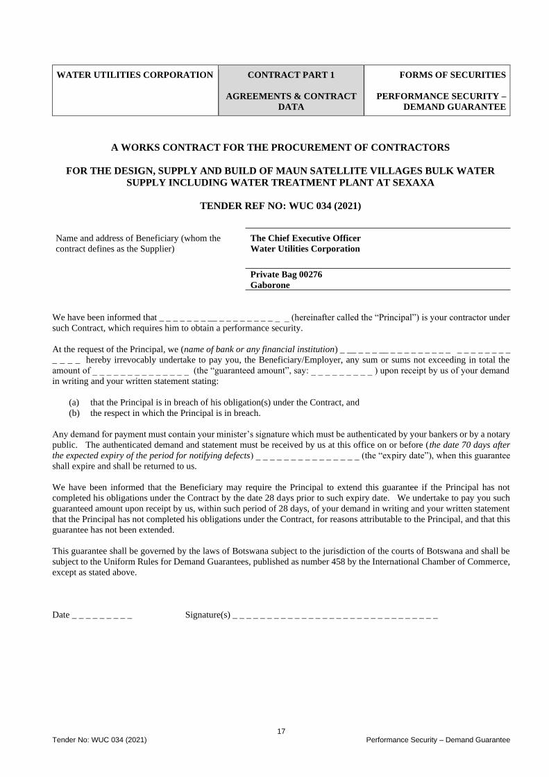
17 Tender No: WUC 034 (2021) Performance Security – Demand Guarantee
WATER UTILITIES CORPORATION
CONTRACT PART 1
AGREEMENTS & CONTRACT
DATA
FORMS OF SECURITIES
PERFORMANCE SECURITY –
DEMAND GUARANTEE
A WORKS CONTRACT FOR THE PROCUREMENT OF CONTRACTORS
FOR THE DESIGN, SUPPLY AND BUILD OF MAUN SATELLITE VILLAGES BULK WATER
SUPPLY INCLUDING WATER TREATMENT PLANT AT SEXAXA
TENDER REF NO: WUC 034 (2021)
Name and address of Beneficiary (whom the
contract defines as the Supplier)
The Chief Executive Officer
Water Utilities Corporation
Private Bag 00276
Gaborone
We have been informed that _ _ _ _ _ _ _ __ _ _ _ _ _ _ _ _ _ _ (hereinafter called the “Principal”) is your contractor under
such Contract, which requires him to obtain a performance security.
At the request of the Principal, we (name of bank or any financial institution) _ __ _ _ _ __ _ _ _ _ _ _ _ _ _ _ _ _ _ _ _ _ _
_ _ _ _ hereby irrevocably undertake to pay you, the Beneficiary/Employer, any sum or sums not exceeding in total the
amount of _ _ _ _ _ _ _ _ _ _ _ _ _ _ (the “guaranteed amount”, say: _ _ _ _ _ _ _ _ _ ) upon receipt by us of your demand
in writing and your written statement stating:
(a) that the Principal is in breach of his obligation(s) under the Contract, and
(b) the respect in which the Principal is in breach.
Any demand for payment must contain your minister’s signature which must be authenticated by your bankers or by a notary
public. The authenticated demand and statement must be received by us at this office on or before (the date 70 days after
the expected expiry of the period for notifying defects) _ _ _ _ _ _ _ _ _ _ _ _ _ _ _ (the “expiry date”), when this guarantee
shall expire and shall be returned to us.
We have been informed that the Beneficiary may require the Principal to extend this guarantee if the Principal has not
completed his obligations under the Contract by the date 28 days prior to such expiry date. We undertake to pay you such
guaranteed amount upon receipt by us, within such period of 28 days, of your demand in writing and your written statement
that the Principal has not completed his obligations under the Contract, for reasons attributable to the Principal, and that this
guarantee has not been extended.
This guarantee shall be governed by the laws of Botswana subject to the jurisdiction of the courts of Botswana and shall be
subject to the Uniform Rules for Demand Guarantees, published as number 458 by the International Chamber of Commerce,
except as stated above.
Date _ _ _ _ _ _ _ _ _ Signature(s) _ _ _ _ _ _ _ _ _ _ _ _ _ _ _ _ _ _ _ _ _ _ _ _ _ _ _ _ _ _
18 Tender No: WUC 034 (2021) Advance Payment Guarantee
WATER UTILITIES CORPORATION
CONTRACT PART 1
AGREEMENTS & CONTRACT
DATA
FORMS OF SECURITIES:
ADVANCED PAYMENT
GUARANTEE
A WORKS CONTRACT FOR THE PROCUREMENT OF CONTRACTORS
FOR THE DESIGN, SUPPLY AND BUILD OF MAUN SATELLITE VILLAGES BULK WATER
SUPPLY INCLUDING WATER TREATMENT PLANT AT SEXAXA
TENDER REF NO: WUC 034 (2021)
Name and address of Beneficiary (whom the
contract defines as the Employer)
The Chief Executive Officer
Water Utilities Corporation
Private Bag 00276
Gaborone
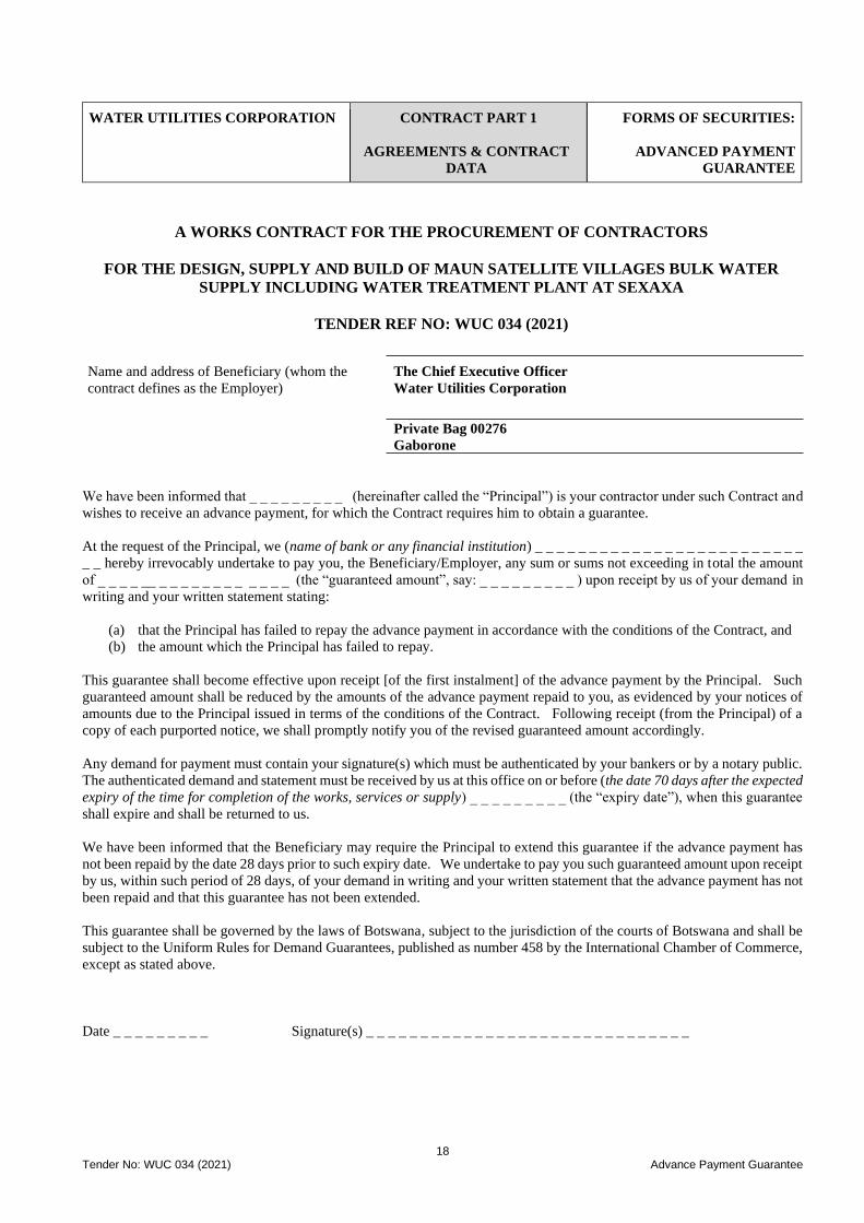
We have been informed that _ _ _ _ _ _ _ _ _ (hereinafter called the “Principal”) is your contractor under such Contract and
wishes to receive an advance payment, for which the Contract requires him to obtain a guarantee.
At the request of the Principal, we (name of bank or any financial institution) _ _ _ _ _ _ _ _ _ _ _ _ _ _ _ _ _ _ _ _ _ _ _ _ _
_ _ hereby irrevocably undertake to pay you, the Beneficiary/Employer, any sum or sums not exceeding in total the amount
of _ _ _ _ __ _ _ _ _ _ _ _ _ _ _ _ _ (the “guaranteed amount”, say: _ _ _ _ _ _ _ _ _ ) upon receipt by us of your demand in
writing and your written statement stating:
(a) that the Principal has failed to repay the advance payment in accordance with the conditions of the Contract, and
(b) the amount which the Principal has failed to repay.
This guarantee shall become effective upon receipt [of the first instalment] of the advance payment by the Principal. Such
guaranteed amount shall be reduced by the amounts of the advance payment repaid to you, as evidenced by your notices of
amounts due to the Principal issued in terms of the conditions of the Contract. Following receipt (from the Principal) of a
copy of each purported notice, we shall promptly notify you of the revised guaranteed amount accordingly.
Any demand for payment must contain your signature(s) which must be authenticated by your bankers or by a notary public.
The authenticated demand and statement must be received by us at this office on or before (the date 70 days after the expected
expiry of the time for completion of the works, services or supply) _ _ _ _ _ _ _ _ _ (the “expiry date”), when this guarantee
shall expire and shall be returned to us.
We have been informed that the Beneficiary may require the Principal to extend this guarantee if the advance payment has
not been repaid by the date 28 days prior to such expiry date. We undertake to pay you such guaranteed amount upon receipt
by us, within such period of 28 days, of your demand in writing and your written statement that the advance payment has not
been repaid and that this guarantee has not been extended.
This guarantee shall be governed by the laws of Botswana, subject to the jurisdiction of the courts of Botswana and shall be
subject to the Uniform Rules for Demand Guarantees, published as number 458 by the International Chamber of Commerce,
except as stated above.
Date _ _ _ _ _ _ _ _ _ Signature(s) _ _ _ _ _ _ _ _ _ _ _ _ _ _ _ _ _ _ _ _ _ _ _ _ _ _ _ _ _ _

19 Tender No: WUC 034 (2021) Form for Adjudicators Appointment
WATER UTILITIES CORPORATION
CONTRACT PART 1
AGREEMENTS & CONTRACT
DATA
FORMS FOR ADJUDICATORS
APPOINTMENT:
FIDIC PLANT & DESIGN BUILD
Users of the FIDIC family of contract documents will find the General Conditions of Dispute Adjudication Agreement and
its Procedural Rules are contained in each copy of the relevant Conditions of Contract (Yellow Book).
A WORKS CONTRACT FOR THE PROCUREMENT OF CONTRACTORS
FOR THE DESIGN, SUPPLY AND BUILD OF MAUN SATELLITE VILLAGES BULK WATER
SUPPLY INCLUDING WATER TREATMENT PLANT AT SEXAXA
TENDER REF NO: WUC 034 (2021)
Name and details of Contract _ _ _ _ _ _ _ _ _ _ _ _ _ _ _ _ _ _ _ _ _ _ _ _ _ _ _ _ _ _ _ _ _ _ _ _ _ _ _ _ _ _ _
Name and address of Employer _ _ _ _ _ _ _ _ _ _ _ _ _ _ _ _ _ _ _ _ _ _ _ _ _ _ _ _ _ _ _ _ _ _ _ _ _ _ _ _ _ _
Name and address of Contractor _ _ _ _ _ _ _ _ _ _ _ _ _ _ _ _ _ _ _ _ _ _ _ _ _ _ _ _ _ _ _ _ _ _ _ _ _ _ _ _ _
Name and address of Member _ _ _ _ _ _ _ _ _ _ _ _ _ _ _ _ _ _ _ _ _ _ _ _ _ _ _ _ _ _ _ _ _ _ _ _ _ _ _ _ _ _ _
Whereas the Employer and the Contractor have entered into the Contract and desire jointly to appoint the Member to act as
sole adjudicator who is also called the “DAB”.
The Employer, Contractor and Member jointly agree as follows:
The conditions of this Dispute Adjudication Agreement comprise the “General Conditions of Dispute Adjudication
Agreement”, which is appended to the General Conditions Of the “Conditions of Contract for Construction” Second Edition
2017 published by the Fédération Internationale des Ingénieurs-Conseils (FIDIC), and the following provisions. In these
provisions, which include amendments and additions to the General Conditions of Dispute Adjudication Agreement, words
and expressions shall have the same meanings as are assigned to them in the General Conditions of Dispute Adjudication
Agreement.
[Details of amendments to the General Conditions of Dispute Adjudication Agreement, stated in Item 2 of the amendments
stated on the previous page of this Annex B shall be inserted here]
In accordance with Clause 6 of the General Conditions of Dispute Adjudication Agreement, the Member shall be paid a daily
fee of _ _ _ _ _ _ _ _ _ per day.
In consideration of these fees and other payments to be made by the Employer and the Contractor in accordance with Clause
6 of the General Conditions of Dispute Adjudication Agreement, the Member undertakes to act as the DAAB (as adjudicator)
in accordance with this Dispute Adjudication Agreement.
The Employer and the Contractor jointly and severally undertake to pay the Member, in consideration of the carrying out of
these services, in accordance with Clause 6 of the General Conditions of Dispute Adjudication Agreement.

20 Tender No: WUC 034 (2021) Form for Adjudicators Appointment
This Dispute Adjudication Agreement shall be governed by the law of the Republic of Botswana.
SIGNED by: SIGNED by: SIGNED
by:
for and on behalf of the Employer
in the presence of
for and behalf of the Contractor in the
presence of
the Member in the presence of
Witness
Witness: Witness:
Name:
Name Name:
Address:
Address: Address:
Date:
Date: Date:

21 Tender No: WUC 034 (2021) Form for Adjudicators Appointment
WATER UTILITIES CORPORATION
CONTRACT PART 2
PRICING DATA
C2.1 PRICING INSTRUCTIONS
A WORKS CONTRACT FOR THE PROCUREMENT OF CONTRACTORS
FOR THE DESIGN, SUPPLY AND BUILD OF MAUN SATELLITE VILLAGES BULK WATER SUPPLY
INCLUDING WATER TREATMENT PLANT AT SEXAXA
TENDER REF NO: WUC 034 (2021)
CONTRACT
Part 2: Pricing Data
C2.1 Pricing Instructions
22 Tender No: WUC 034 (2021) Form for Adjudicators Appointment
WATER UTILITIES
CORPORATION
CONTRACT PART 2
PRICING DATA
C2.1 PRICING INSTRUCTION
A WORKS CONTRACT FOR THE PROCUREMENT OF CONTRACTORS
FOR THE DESIGN, SUPPLY AND BUILD OF MAUN SATELLITE VILLAGES BULK WATER SUPPLY
INCLUDING WATER TREATMENT PLANT AT SEXAXA
TENDER REF NO: WUC 034 (2021) Pricing Instruction
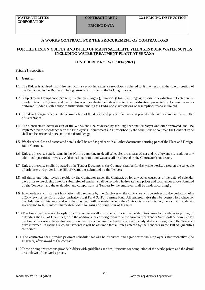
1. General
1.1 The Bidder is advised that if the instructions set out hereafter are not closely adhered to, it may result, at the sole discretion of
the Employer, in the Bidder not being considered further in the bidding process.
1.2 Subject to the Compliance (Stage 1), Technical (Stage 2), Financial (Stage 3 & Stage 4) criteria for evaluation reflected in the
Tender Data the Engineer and the Employer will evaluate the bids and enter into clarification, presentation discussions with a
preferred Bidder/s with a view to fully understanding the Bid/s and clarifications of assumptions made in the bid.
1.3 The detail design process entails completion of the design and project plan work as priced in the Works pursuant to a Letter
of Acceptance.
1.4 The Contractor’s detail design of the Works shall be reviewed by the Engineer and Employer and once approved, shall be
implemented in accordance with the Employer’s Requirements. As prescribed by the conditions of contract, the Contract Price
shall not be amended pursuant to the detail design.
1.5 Works schedules and associated details shall be read together with all other documents forming part of the Plant and Design-
Build Contract.
1.6 Unless otherwise stated, items in the Work’s components detail schedules are measured net and no allowance is made for any
additional quantities or waste. Additional quantities and waste shall be allowed in the Contractor’s unit rates.
1.7 Unless otherwise explicitly stated in the Tender Documents, the Contract shall be for the whole works, based on the schedule
of unit rates and prices in the Bill of Quantities submitted by the Tenderer.
1.8 All duties and other levies payable by the Contractor under the Contract, or for any other cause, as of the date 30 calendar
days prior to the closing date for submission of tenders, shall be included in the rates and prices and total tender price submitted
by the Tenderer, and the evaluation and comparisons of Tenders by the employer shall be made according1y.
1.9 In accordance with current legislation, all payments by the Employer to the contractor will be subject to the deduction of a
0.25% levy for the Construction Industry Trust Fund (CITF) training fund. All tendered rates shall be deemed to include for
the deduction of this levy, and no other payment will be made through the Contract to cover this levy deduction. Tenderers
are advised to fully inform themselves with the terms and conditions of the levy.
1.10 The Employer reserves the right to adjust arithmetically or other errors in the Tender. Any error by Tenderer in pricing or
extending the Bill of Quantities, or in the additions, or carrying forward to the summary or Tender Sum shall be corrected by
the Employer during the evaluation of tenders. In such a case the tender sum shall be adjusted accordingly and the Tenderer
duly informed. In making such adjustments it will be assumed that all rates entered by the Tenderer in the Bill of Quantities
are correct.
1.11 The contractor shall provide payment schedule that will be discussed and agreed with the Employer’s Representative (the
Engineer) after award of the contract.
1.12 These pricing instructions provide bidders with guidelines and requirements for completion of the works prices and the detail
break down of the works prices.
23 Tender No: WUC 034 (2021) Form for Adjudicators Appointment
1.13 The contractor shall develop a detailed bill of quantities upon which he will prepare an indicative payment schedule to be
agreed with the Employer
2. Quantities
2.1 Quantities included in the Works detail schedules are the estimated quantities of work derived from the conceptual design
produced by the Engineer (where the conceptual designs are still applicable) and these are provided for guidance of
envisaged works only. These quantities do not represent the final amount of work and elements to be executed. In his pricing
the Contractor should therefore allow for all other items and elements that he deems would be required to deliver a project
that will meet the Employer’s requirements as detailed in the tender document & conceptual design reports.
2.2 Under the Plant and Design-Build conditions of contract the Contract Price is fixed and firm except for price indexation,
variations to the Employer’s Requirements and other relief provided for in the Contract.
3. Rates and Prices
3.1 Rates and prices inserted in Works detail schedules are to be the fully inclusive base date prices for the Works described under
each item. Rates and prices shall cover all costs and expenses (except escalation) that may be required in and for the execution
of the work described, and shall cover the cost of all risks, liabilities and obligations set forth or implied in the Employer’s
Requirements as well as direct and indirect overhead charges and profit.
3.2 A schedule of rates for the valuation of Variations to the Employer’s Requirements shall be included with the Contractor’s
Documents (Returnable Documents).
3.3 Rates and prices inserted in Works detail schedules must be broken down into the components shown - material, plant, labour,
sundries, risk and profit.
3.4 Rates and prices shall be the rates and prices at the Base Date (as determined in the Appendix).
3.5 A price or rate shall be entered against each item in the Works detail schedules whether quantities are stated or not. An item
against which no price is entered or where a word or phrase such as “included” or “provided elsewhere” is entered will be
accepted as a rate of nil (BWP 0.00).
3.6 The Bidder shall not group together several items in the Works detail schedules and tender one rate for such group of items.
3.7 All rates and sums of money quoted in the Works detail schedules shall be quoted in Botswana Pula.
3.8 All prices and rates entered in the Works detail schedules must exclude value added tax (VAT). VAT shall be chargeable in
accordance with the Contract and the applicable Laws.
Any failure by the Contractor to discover matters which affect, or could affect, the Work shall not relieve the Contractor
from its obligations under the Contract or otherwise affect the Contract Price or Time.
4. Day Works
4.1 The Bill of Quantities for Day Works (Emergency) shall be read in conjunction with the Instructions to Bidders, conditions
of Contract, Specifications and the Drawings submitted by the constructor.
4.2 Actual quantities for Day Works (Emergency) will be specified in Work Orders, issued by the Engineer in accordance with
the General Conditions. The basis of payment for Day (Emergency) Works will be the actual quantities of work ordered and
carried out, as measured by the Contractor and verified by the Engineer and valued at the unit rates and prices bid in the priced
Bill of Quantities, where applicable, and otherwise at such Unit rates and prices as may be agreed or determined by the
Engineer under the provisions of the Contract.
4.3 The unit rates and prices bid in the priced Bill of Quantities shall, except insofar as is otherwise provided under the Contract,
include all plant, equipment, labour, supervision, materials, erection, maintenance, insurance, profit, taxes and duties, together
with all general risks, liabilities and obligations set out or implied in the Contract.

24 Tender No: WUC 034 (2021) Form for Adjudicators Appointment
4.4 The unit rates and prices shall be quoted in the same currency used in the financial proposal.
4.5 A unit rate or price shall be entered against each item in the Bill of Quantities. The cost of items against which the Contractor
has failed to enter a unit rate or price shall be deemed to be covered by the other unit rates and prices entered in the Bill of
Quantities.
4.6 General directions and descriptions of work and materials are not repeated or summarized in the Bill of Quantities. References
to the relevant sections of the Contract documentation shall be made before entering rates or prices against each item in the
Bill of Quantities.
4.7 The method of measurement of completed works for payment shall be in accordance with the measurement and payment
provisions of the relevant section of the Specifications.
4.8 Arithmetical errors discovered prior to award of the Contract shall be corrected by the Employer.
NB: For the Day (Emergency) Works, payments shall be made for each emergency on a case-to-case basis provided in the Contract,
based on the actual work quantities approved by the Employer and using the Bill of Quantities rates inclusive of price adjustments
where appropriate.
25 Tender No: WUC 034 (2021) Form for Adjudicators Appointment
WATER UTILITIES
CORPORATION
CONTRACT PART 3
SCOPE OF WORKS
A WORKS CONTRACT FOR THE PROCUREMENT OF CONTRACTORS
FOR THE DESIGN, SUPPLY AND BUILD OF MAUN SATELLITE VILLAGES BULK WATER SUPPLY
INCLUDING WATER TREATMENT PLANT AT SEXAXA
TENDER REF NO: WUC 034 (2021)
Contract
Part 3: Scope of Work
C3.1 General
C3.2 Employers Requirements (Scope of Works)
C3.3 Specifications
26 Tender No: WUC 034 (2021) Scope of Works
WATER UTILITIES CORPORATION
CONTRACT PART 3
SCOPE OF WORK
C3.1 GENERAL
A WORKS CONTRACT FOR THE PROCUREMENT OF CONTRACTORS
FOR THE DESIGN, SUPPLY AND BUILD OF MAUN SATELLITE VILLAGES BULK WATER
SUPPLY INCLUDING WATER TREATMENT PLANT AT SEXAXA
TENDER REF NO: WUC 034 (2021)
1 GENERAL
1.1 Background Satellite villages bulk water supply including treatment plant at Sexaxa is intended to upgrade the Satellite Villages Water
supply transfer scheme to meet the villages water requirements up to the year 2038 design horizon. The project includes raw
and clear water tanks, drilling of replacement boreholes, borehole equipping, borehole collector lines, transmission pipelines
from the proposed water treatment plant to Sexaxa, Matsaudi, Sakapane and Shorobe villages including instrumentation and
control. The implementation of the project will be through the Plant and Design-Build Contract for water transfer scheme
and telemetry and SCADA including instrumentation, control and associated works
A conceptual design was prepared for the works by the Engineer. This conceptual design was adopted by Project Management
Office, who were he Client during the projects conceptual design phase.
The conceptual design phase of the project, which was completed in 2015, was implemented in five stages as noted below.
• Stage I – Existing Network Optimisation
• Stage II – Conceptual Design Study
• Stage III – Feasibility Study
• Stage IV – Tender Documentation
• Stage V – Construction
The construction phase of the project will be implemented via four different projects, three of which are interdependent.
These contracts are:
• Contract 1 - Design, Supply and Build of Water Distribution Network, Sanitation Reticulation, Telemetry and
SCADA and Associated Works in Maun
• Contract 2 - Design, Supply and Build of Boreholes Equipping, Boreholes Collector Lines, Booster Station, Water
Treatment Plant (Including Raw and Clear Water Tanks)
• Contract 3 - Design, Supply and Build of Wastewater Treatment Plants (Maun East and Maun West) Including
Instrumentation and Control and Associated Works
• Contract 4 - Design, Supply and Build of Maun Satellite Villages Bulk Water Supply Including Treatment Plant at
Sexaxa
The above four contracts were preceded by the Network Optimisation contract, whose objective was to make more efficient
the existing network through zoning and provision of zone booster stations and zone supply tanks. As of August 2021,
Contracts 1 & 2 are being implemented on site, whilst Contract 3 (and Contract 4) are in the tender management stage.
This tender document has been prepared for ‘Contract 4 - Plant and Design-Build Contract for Maun Satellite Villages
Bulk Water Supply Including Water Treatment Plant at Sexaxa’ and describes the Employer’s requirements for the
implementation of the contract.
1.2.1 Project Objective
Maun water supply has been and continues to be characterised by poor water supply resulting in shortage of water in Maun.
The water shortage extends to the villages around Maun, including Sexaxa, Matsaudi, Sakapane and Shorobe. The said

27 Tender No: WUC 034 (2021) Scope of Works
villages, except for Shorobe, are supplied from boreholes in the Sexaxa (Upper Thamalakane) Wellfield. The boreholes
experience frequent breakdown and access challenges when the Thamalakane River is filled with water. Shorobe supply is
from a borehole in the village with a low yield and that experiences frequent breakdowns.
The above, and various other operational challenges besiege the water supply scheme to these villages and therefore a more
reliable scheme must be implemented. The objective of the project is therefore to improve the water supply scheme by
connecting additional boreholes, put in place measures that will improve operations, treat the groundwater to compulsory
drinking water standard – BOS32:2015 requirements and ensure that the supply to the satellite villages is adequate up to year
2038, the project design horizon. This objective shall be met through:
• Drilling of 7No replacement boreholes at Sexaxa including test pumping of new boreholes to give recommended
yield and sampling and testing of raw water for confirmation of water quality.
• Equipping all replacement boreholes
• Extension of electricity transmission and electrification of replacement boreholes
• Provision of collector lines and transmission mains from boreholes to Sexaxa Treatment Plant Site
• Provision of a water treatment plant to treat raw water from the boreholes
• Site buildings, including operator office, guardhouse and chemical storage building
• New transmission mains from Sexaxa Water Treatment Plant site to elevated tanks at Sexaxa, Matsaudi / Sakapane
and Shorobe
• Telemetry and SCADA for remote monitoring and control of the wellfield, water treatment plant & storage tanks
• Staff Housing
• Access Road from Maun-Shorobe Road to the plant site and internal access roads to site building and water treatment
plant.
• Pedestrian walkways to link all site building and water treatment plant
The works that are carried out shall be complemented by Contract 1 Design, Supply and Build of Water Distribution Network,
Sanitation Reticulation, Telemetry and SCADA and Associated Works in Maun, which will improve the distribution system
in Maun through provision of new pipelines, zones, zone booster station and other associated works.
The ensuing sections of this document describes the Employer’s requirements for the implementation of the works and
describes the expectations of the Employer (Water Utilities Corporation) with regards to Contract 4 works and spells out the
performance criteria for the works components.
The sections further describe the tasks which the Contractor needs to undertake to satisfactorily achieve the objectives of the
assignment. The Contractor shall appraise conceptual designs for the satellite villages and shall develop these concepts further
to provide a complete detailed design and implement it through construction phase and remedy any defects during the Defects
Notification Period.
1.2.2 The Employer
Corporate Profile
Water Utilities Corporation (WUC) was established in 1970 through an Act of Parliament. The mandate of the Corporation
is to provide potable and wastewater services throughout the country.
The Corporation is a parastatal organization wholly owned by the Botswana Government. A Board of Directors appointed
by the Minister of Land Management Water and Sanitation Services is the overall authority responsible for policy
formulation. WUC has eight (8) Departments namely: Chief Executive’s Office, Technical Services, Operations, Shared

28 Tender No: WUC 034 (2021) Scope of Works
Services, Finance, Sustainability and Water Resources, Human Resource, Corporation Secretariat and Internal Audit. The
departmental heads report to the Chief Executive who in turn reports to the Board.
Corporate Governance
Water Utilities Corporation subscribes to and is committed to the accepted practices of good governance and international
best practice. In all its undertakings, the Corporation shall not tolerate fraud, corruption, malpractice or maladministration.
The Corporation further commits to preventing, detecting and timely responding to issues of fraud, corruption, malpractice
or maladministration, and expects its employees, suppliers, contractors, contractors, general members of the public to be fair
and honest in their dealings with the Corporation. The Corporation maintains an open-door policy, where issues relating to
fraud, corruption, malpractice or maladministration can be freely reported through the hotline/tip-off anonymous program
and/or Internal Audit. Issues can be reported through, writing, email, telephone or in person.
29 Tender No: WUC 034 (2021) Scope of Works
WATER UTILITIES CORPORATION
CONTRACT PART 3
SCOPE OF WORK
C3.2 EMPLOYER’S
REQUIREMENTS
C3.2 EMPLOYER REQUIREMENTS (THE SCOPE OF WORKS)
The Plant and Design-Build Contractor shall carry out the works under Contract 4 - Plant and Design-Build Contract for
Maun Satellite Villages Bulk Water Supply Including Water Treatment Plant at Sexaxa.
This section describes the Employers Requirements and the tasks which the Contractor needs to undertake to satisfactorily
achieve the objectives of the assignment. The outline is not intended to place limitations on the Contractors activities, but
instead, it is expected that having examined these, the Contractor shall incorporate such additional items as he deems
necessary to achieve the project objectives.
C3.2.1 Engineering Concepts
Engineering concepts have been developed and are as contained in the reports scheduled below. The concepts do not
constitute a detailed design but illustrate the development of the engineering concepts and are meant to provide a guide to
the Contractor. The Employer’s Requirements take precedence over the Conceptual Design reports. The Contractor shall be
responsible to the Employer for the design, supply, construction, testing, commissioning and operation of the Works in
accordance with the Employer’s Requirements as described in the ensuing sub-sections.
The Contractor shall also take complete responsibility for the review of conceptual design reports (available at the Employer’s
offices) and carry out detailed design and construction of the works. The reports are available in the following documents:
• Volume 1 Executive Summary
• Volume 2 Water Conceptual Design Study Report
• Volume 2.1 Water Conceptual Design Study Attachment 2: Existing and Future zones and Proposed
Works
• Volume 2.2 Satellite Villages Conceptual Design Study Report
• Volume 3 Sanitation Conceptual Design Report (if required)
• Volume 4 Surface Water and Groundwater Resources Report
• Volume 5 Topographical and Geotechnical Survey Conceptual Design Report
These Employers Requirements, including performance criteria shall be read in conjunction with the Contract Preliminaries,
the Water Conceptual Design Report, Satellite Villages Conceptual Design Study Report, Surface Water and Groundwater
Resources Report and any other available drawings and Contract Documents.
The Bidder is made aware of changes to the project boreholes as contained in the conceptual design report. Some of the
boreholes have been upgraded from diesel to electric driven motors as a measure by the WUC (the operator) to address
operational challenges in the wellfield. The Bidder shall take note of the current situation as would have been observed at the
site visit and shall prepare his bid (technical and financial) in consideration of the status.
C3.2.1.1 Coordination of Works with Other Works Contracts
C3.2.1.1.1 Coordination The works as described hereunder are a component of the Maun Water Supply and Sanitation Phase II project which is being
let out in four contracts as follows:
• Contract 1 - Design, Supply and Build of Water Distribution Network, Sanitation Reticulation, Telemetry and
SCADA and Associated Works in Maun
30 Tender No: WUC 034 (2021) Scope of Works
• Contract 2 - Design, Supply and Build of Boreholes Equipping, Boreholes Collector Lines, Booster Station, Water
Treatment Plant (Including Raw and Clear Water Tanks)
• Contract 3 - Design, Supply and Build of Wastewater Treatment Plants (Maun East and Maun West) Including
Instrumentation and Control and Associated Works
• Contract 4 - Design, Supply and Build of Maun Satellite Villages Bulk Water Supply Including Treatment Plant at
Sexaxa
The above noted contracts were preceded by the Network Optimisation Works whose objective was to optimise and make
more efficient the existing water supply network and some components of the existing sanitation scheme. The four contracts
and the optimisation works are interdependent in some quarters and will be delivered in parallel at some stage of their
implementation. For instance:
• The potable water that is to be provided under this contract, Contract 2, shall be collected and distributed in Maun
through Contract 1. As a result, the water treatment plant should be able to produce potable water volumes as
demanded in Maun (Maun demand <= Potable water from Nxaraga).
• The Telemetry and SCADA for Contract 4 shall be linked with the Telemetry and SCADA system at the
Thamalakane Command Centre in Maun from where Contract 4 can also be monitored and operated from. The
system at the treatment plant and at the Command Centre shall therefore be compatible
In cognisance of the above, there will be a need for coordination by the contractors tasked with implementing the different
contracts especially as the contracts will run in parallel at some stages of implementation. The Plant and Design-Build
Contractor shall plan for and accommodate these other parties where interface occurs and work in suitable cooperation with
a view to complete the project within the Time(s) for Completion. The cost of coordinating with the other contractors shall
be included in the overall costs.
C3.2.1.1.2 Termination and Pick-Up Points
This section seeks to define the termination and pick-up points for Contract 4. The termination points are defined as the
extent or battery limits for Contract 4 and where the other contracts will pick up the works. The termination points are also
areas where Contract 4 aspects will pick up the terminations from the other contracts. Coordination will be required with
Contract 1 for the telemetry components (local centre at the treatment plant and the Command Centre at Thamalakane,
Maun).
The termination point applies:
i. Contract 4 Terminations
Telemetry – A local telemetry centre will be established at Sexaxa Water Treatment Plant to monitor and
control the water treatment plant, raw and clear water tanks, pump station and the boreholes. This telemetry
centre shall have the necessary equipment to communicate with Thamalakane Network Command Centre to
be established under Contract 1 and the two Contractors shall coordinate to ensure that this is adequately met.
C3.2.1.1.3 Work Prioritisation The Contractor shall prioritise his work as follows:
1. Staff Housing
The Contractor shall prioritise design and construction of the proposed project housing to allow occupancy of the units within
4months of project commencement. The project housing shall be using by monitoring staff and therefore they must be
completed in time to allow the occupancy at the start of the construction works.
2. Replacement Boreholes
The Contractor shall immediate after award, commence the activity to replace the 7No production boreholes in the Sexaxa
Wellfield and confirm the appropriate pumping rates and durations. The Contrator shall sample and analyse the raw water
from the boreholes to confirm the quality for input into the water treatment plant design. The replacement boreholes shall be
drilled within 10m of the boreholes they are replacing and shall be connected to the scheme within the project duration. The
10m radius for replacement boreholes is not cast in stone. The Contractor, through his Hydrogeologist shall assess the
wellfield and the risks on the replacement of the boreholes and adequately cost against this risk.
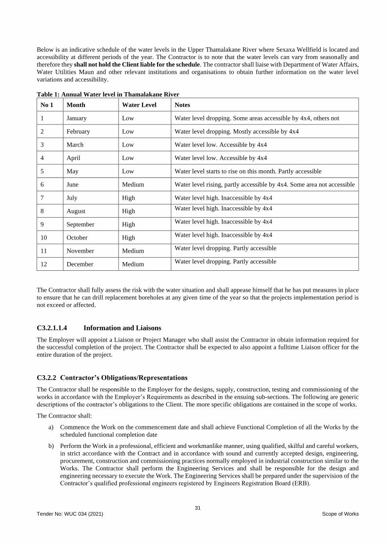
31 Tender No: WUC 034 (2021) Scope of Works
Below is an indicative schedule of the water levels in the Upper Thamalakane River where Sexaxa Wellfield is located and
accessibility at different periods of the year. The Contractor is to note that the water levels can vary from seasonally and
therefore they shall not hold the Client liable for the schedule. The contractor shall liaise with Department of Water Affairs,
Water Utilities Maun and other relevant institutions and organisations to obtain further information on the water level
variations and accessibility.
Table 1: Annual Water level in Thamalakane River
No 1 Month Water Level Notes
1 January Low Water level dropping. Some areas accessible by 4x4, others not
2 February Low Water level dropping. Mostly accessible by 4x4
3 March Low Water level low. Accessible by 4x4
4 April Low Water level low. Accessible by 4x4
5 May Low Water level starts to rise on this month. Partly accessible
6 June Medium Water level rising, partly accessible by 4x4. Some area not accessible
7 July High Water level high. Inaccessible by 4x4
8 August High Water level high. Inaccessible by 4x4
9 September High Water level high. Inaccessible by 4x4
10 October High Water level high. Inaccessible by 4x4
11 November Medium Water level dropping. Partly accessible
12 December Medium Water level dropping. Partly accessible
The Contractor shall fully assess the risk with the water situation and shall appease himself that he has put measures in place
to ensure that he can drill replacement boreholes at any given time of the year so that the projects implementation period is
not exceed or affected.
C3.2.1.1.4 Information and Liaisons
The Employer will appoint a Liaison or Project Manager who shall assist the Contractor in obtain information required for
the successful completion of the project. The Contractor shall be expected to also appoint a fulltime Liaison officer for the
entire duration of the project.
C3.2.2 Contractor’s Obligations/Representations
The Contractor shall be responsible to the Employer for the designs, supply, construction, testing and commissioning of the
works in accordance with the Employer’s Requirements as described in the ensuing sub-sections. The following are generic
descriptions of the contractor’s obligations to the Client. The more specific obligations are contained in the scope of works.
The Contractor shall:
a) Commence the Work on the commencement date and shall achieve Functional Completion of all the Works by the
scheduled functional completion date
b) Perform the Work in a professional, efficient and workmanlike manner, using qualified, skilful and careful workers,
in strict accordance with the Contract and in accordance with sound and currently accepted design, engineering,
procurement, construction and commissioning practices normally employed in industrial construction similar to the
Works. The Contractor shall perform the Engineering Services and shall be responsible for the design and
engineering necessary to execute the Work. The Engineering Services shall be prepared under the supervision of the
Contractor’s qualified professional engineers registered by Engineers Registration Board (ERB).
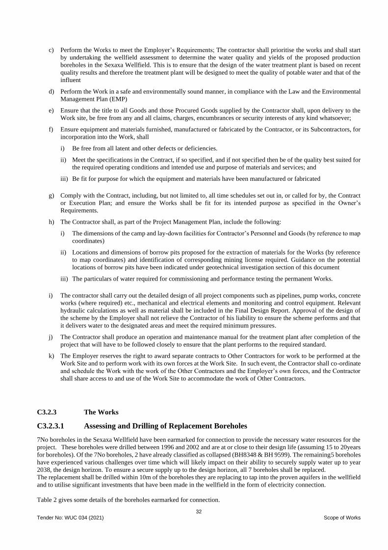
32 Tender No: WUC 034 (2021) Scope of Works
c) Perform the Works to meet the Employer’s Requirements; The contractor shall prioritise the works and shall start
by undertaking the wellfield assessment to determine the water quality and yields of the proposed production
boreholes in the Sexaxa Wellfield. This is to ensure that the design of the water treatment plant is based on recent
quality results and therefore the treatment plant will be designed to meet the quality of potable water and that of the
influent
d) Perform the Work in a safe and environmentally sound manner, in compliance with the Law and the Environmental
Management Plan (EMP)
e) Ensure that the title to all Goods and those Procured Goods supplied by the Contractor shall, upon delivery to the
Work site, be free from any and all claims, charges, encumbrances or security interests of any kind whatsoever;
f) Ensure equipment and materials furnished, manufactured or fabricated by the Contractor, or its Subcontractors, for
incorporation into the Work, shall
i) Be free from all latent and other defects or deficiencies.
ii) Meet the specifications in the Contract, if so specified, and if not specified then be of the quality best suited for
the required operating conditions and intended use and purpose of materials and services; and
iii) Be fit for purpose for which the equipment and materials have been manufactured or fabricated
g) Comply with the Contract, including, but not limited to, all time schedules set out in, or called for by, the Contract
or Execution Plan; and ensure the Works shall be fit for its intended purpose as specified in the Owner’s
Requirements.
h) The Contractor shall, as part of the Project Management Plan, include the following:
i) The dimensions of the camp and lay-down facilities for Contractor’s Personnel and Goods (by reference to map
coordinates)
ii) Locations and dimensions of borrow pits proposed for the extraction of materials for the Works (by reference
to map coordinates) and identification of corresponding mining license required. Guidance on the potential
locations of borrow pits have been indicated under geotechnical investigation section of this document
iii) The particulars of water required for commissioning and performance testing the permanent Works.
i) The contractor shall carry out the detailed design of all project components such as pipelines, pump works, concrete
works (where required) etc., mechanical and electrical elements and monitoring and control equipment. Relevant
hydraulic calculations as well as material shall be included in the Final Design Report. Approval of the design of
the scheme by the Employer shall not relieve the Contractor of his liability to ensure the scheme performs and that
it delivers water to the designated areas and meet the required minimum pressures.
j) The Contractor shall produce an operation and maintenance manual for the treatment plant after completion of the
project that will have to be followed closely to ensure that the plant performs to the required standard.
k) The Employer reserves the right to award separate contracts to Other Contractors for work to be performed at the
Work Site and to perform work with its own forces at the Work Site. In such event, the Contractor shall co-ordinate
and schedule the Work with the work of the Other Contractors and the Employer’s own forces, and the Contractor
shall share access to and use of the Work Site to accommodate the work of Other Contractors.
C3.2.3 The Works
C3.2.3.1 Assessing and Drilling of Replacement Boreholes
7No boreholes in the Sexaxa Wellfield have been earmarked for connection to provide the necessary water resources for the
project. These boreholes were drilled between 1996 and 2002 and are at or close to their design life (assuming 15 to 20years
for boreholes). Of the 7No boreholes, 2 have already classified as collapsed (BH8348 & BH 9599). The remaining5 boreholes
have experienced various challenges over time which will likely impact on their ability to securely supply water up to year
2038, the design horizon. To ensure a secure supply up to the design horizon, all 7 boreholes shall be replaced.
The replacement shall be drilled within 10m of the boreholes they are replacing to tap into the proven aquifers in the wellfield
and to utilise significant investments that have been made in the wellfield in the form of electricity connection.
Table 2 gives some details of the boreholes earmarked for connection.
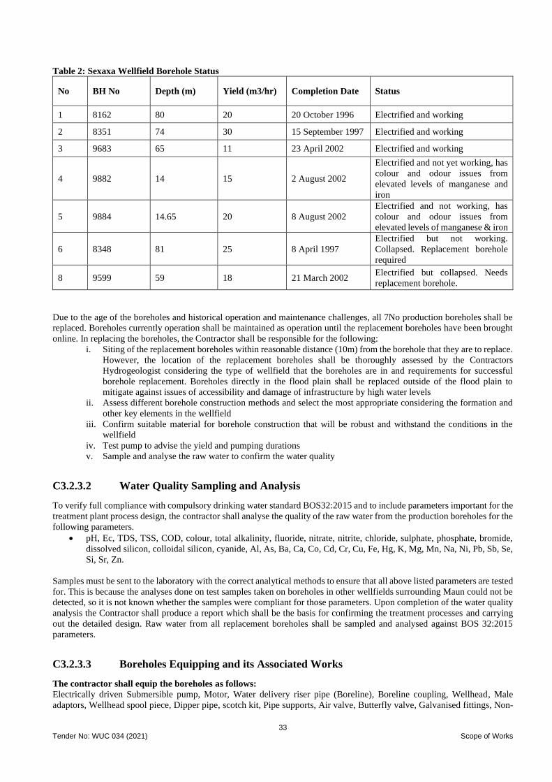
33 Tender No: WUC 034 (2021) Scope of Works
Table 2: Sexaxa Wellfield Borehole Status
No BH No Depth (m) Yield (m3/hr) Completion Date Status
1 8162 80 20 20 October 1996 Electrified and working
2 8351 74 30 15 September 1997 Electrified and working
3 9683 65 11 23 April 2002 Electrified and working
4 9882 14 15 2 August 2002
Electrified and not yet working, has
colour and odour issues from
elevated levels of manganese and
iron
5 9884 14.65 20 8 August 2002
Electrified and not working, has
colour and odour issues from
elevated levels of manganese & iron
6 8348 81 25 8 April 1997
Electrified but not working.
Collapsed. Replacement borehole
required
8 9599 59 18 21 March 2002 Electrified but collapsed. Needs
replacement borehole.
Due to the age of the boreholes and historical operation and maintenance challenges, all 7No production boreholes shall be
replaced. Boreholes currently operation shall be maintained as operation until the replacement boreholes have been brought
online. In replacing the boreholes, the Contractor shall be responsible for the following:
i. Siting of the replacement boreholes within reasonable distance (10m) from the borehole that they are to replace.
However, the location of the replacement boreholes shall be thoroughly assessed by the Contractors
Hydrogeologist considering the type of wellfield that the boreholes are in and requirements for successful
borehole replacement. Boreholes directly in the flood plain shall be replaced outside of the flood plain to
mitigate against issues of accessibility and damage of infrastructure by high water levels
ii. Assess different borehole construction methods and select the most appropriate considering the formation and
other key elements in the wellfield
iii. Confirm suitable material for borehole construction that will be robust and withstand the conditions in the
wellfield
iv. Test pump to advise the yield and pumping durations
v. Sample and analyse the raw water to confirm the water quality
C3.2.3.2 Water Quality Sampling and Analysis
To verify full compliance with compulsory drinking water standard BOS32:2015 and to include parameters important for the
treatment plant process design, the contractor shall analyse the quality of the raw water from the production boreholes for the
following parameters.
• pH, Ec, TDS, TSS, COD, colour, total alkalinity, fluoride, nitrate, nitrite, chloride, sulphate, phosphate, bromide,
dissolved silicon, colloidal silicon, cyanide, Al, As, Ba, Ca, Co, Cd, Cr, Cu, Fe, Hg, K, Mg, Mn, Na, Ni, Pb, Sb, Se,
Si, Sr, Zn.
Samples must be sent to the laboratory with the correct analytical methods to ensure that all above listed parameters are tested
for. This is because the analyses done on test samples taken on boreholes in other wellfields surrounding Maun could not be
detected, so it is not known whether the samples were compliant for those parameters. Upon completion of the water quality
analysis the Contractor shall produce a report which shall be the basis for confirming the treatment processes and carrying
out the detailed design. Raw water from all replacement boreholes shall be sampled and analysed against BOS 32:2015
parameters.
C3.2.3.3 Boreholes Equipping and its Associated Works
The contractor shall equip the boreholes as follows:
Electrically driven Submersible pump, Motor, Water delivery riser pipe (Boreline), Boreline coupling, Wellhead, Male
adaptors, Wellhead spool piece, Dipper pipe, scotch kit, Pipe supports, Air valve, Butterfly valve, Galvanised fittings, Non-
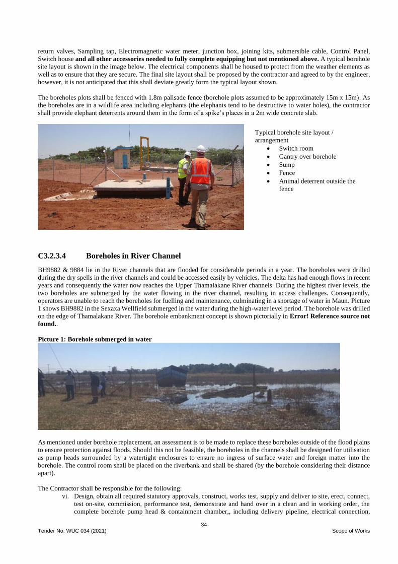
34 Tender No: WUC 034 (2021) Scope of Works
return valves, Sampling tap, Electromagnetic water meter, junction box, joining kits, submersible cable, Control Panel,
Switch house and all other accessories needed to fully complete equipping but not mentioned above. A typical borehole
site layout is shown in the image below. The electrical components shall be housed to protect from the weather elements as
well as to ensure that they are secure. The final site layout shall be proposed by the contractor and agreed to by the engineer,
however, it is not anticipated that this shall deviate greatly form the typical layout shown.
The boreholes plots shall be fenced with 1.8m palisade fence (borehole plots assumed to be approximately 15m x 15m). As
the boreholes are in a wildlife area including elephants (the elephants tend to be destructive to water holes), the contractor
shall provide elephant deterrents around them in the form of a spike’s places in a 2m wide concrete slab.
C3.2.3.4 Boreholes in River Channel
BH9882 & 9884 lie in the River channels that are flooded for considerable periods in a year. The boreholes were drilled
during the dry spells in the river channels and could be accessed easily by vehicles. The delta has had enough flows in recent
years and consequently the water now reaches the Upper Thamalakane River channels. During the highest river levels, the
two boreholes are submerged by the water flowing in the river channel, resulting in access challenges. Consequently,
operators are unable to reach the boreholes for fuelling and maintenance, culminating in a shortage of water in Maun. Picture
1 shows BH9882 in the Sexaxa Wellfield submerged in the water during the high-water level period. The borehole was drilled
on the edge of Thamalakane River. The borehole embankment concept is shown pictorially in Error! Reference source not
found..
Picture 1: Borehole submerged in water
As mentioned under borehole replacement, an assessment is to be made to replace these boreholes outside of the flood plains
to ensure protection against floods. Should this not be feasible, the boreholes in the channels shall be designed for utilisation
as pump heads surrounded by a watertight enclosures to ensure no ingress of surface water and foreign matter into the
borehole. The control room shall be placed on the riverbank and shall be shared (by the borehole considering their distance
apart).
The Contractor shall be responsible for the following:
vi. Design, obtain all required statutory approvals, construct, works test, supply and deliver to site, erect, connect,
test on-site, commission, performance test, demonstrate and hand over in a clean and in working order, the
complete borehole pump head & containment chamber,, including delivery pipeline, electrical connection,
Typical borehole site layout /
arrangement
• Switch room
• Gantry over borehole
• Sump
• Fence
• Animal deterrent outside the
fence
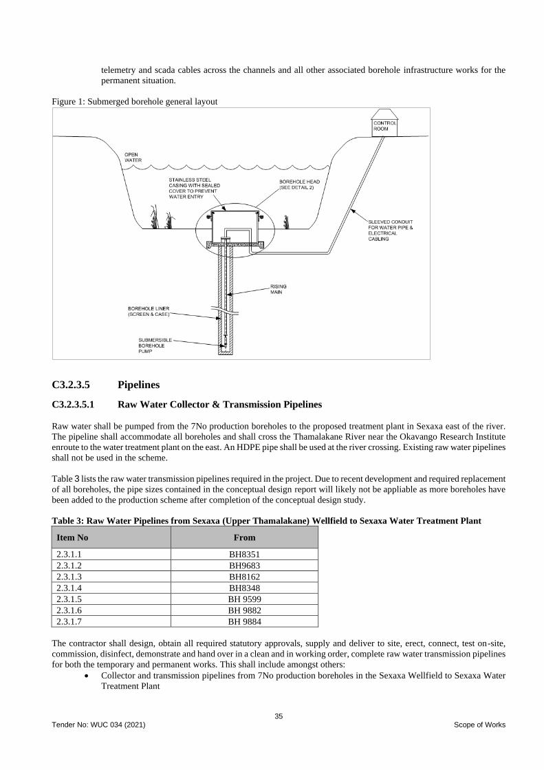
35 Tender No: WUC 034 (2021) Scope of Works
telemetry and scada cables across the channels and all other associated borehole infrastructure works for the
permanent situation.
Figure 1: Submerged borehole general layout
C3.2.3.5 Pipelines
C3.2.3.5.1 Raw Water Collector & Transmission Pipelines
Raw water shall be pumped from the 7No production boreholes to the proposed treatment plant in Sexaxa east of the river.
The pipeline shall accommodate all boreholes and shall cross the Thamalakane River near the Okavango Research Institute
enroute to the water treatment plant on the east. An HDPE pipe shall be used at the river crossing. Existing raw water pipelines
shall not be used in the scheme.
Table 3 lists the raw water transmission pipelines required in the project. Due to recent development and required replacement
of all boreholes, the pipe sizes contained in the conceptual design report will likely not be appliable as more boreholes have
been added to the production scheme after completion of the conceptual design study.
Table 3: Raw Water Pipelines from Sexaxa (Upper Thamalakane) Wellfield to Sexaxa Water Treatment Plant
Item No From
2.3.1.1 BH8351
2.3.1.2 BH9683
2.3.1.3 BH8162
2.3.1.4 BH8348
2.3.1.5 BH 9599
2.3.1.6 BH 9882
2.3.1.7 BH 9884
The contractor shall design, obtain all required statutory approvals, supply and deliver to site, erect, connect, test on-site,
commission, disinfect, demonstrate and hand over in a clean and in working order, complete raw water transmission pipelines
for both the temporary and permanent works. This shall include amongst others:
• Collector and transmission pipelines from 7No production boreholes in the Sexaxa Wellfield to Sexaxa Water
Treatment Plant

36 Tender No: WUC 034 (2021) Scope of Works
C3.2.3.5.2 Treated Water Transmission Pipelines
The table below shows the proposed transmission pipeline sizes delivering water to Sexaxa, Matsaudi & Sakapane and
Shorobe demand centres. The pipe lengths are indicative, the Contrator shall size and confirm the length of the pipelines as
the Employer will not be held accountable for the lengths shown and no additional costs shall be accepted for longer lengths.
Item No Line
Cl. Dia (mm) Length (m) From To
2.3.2.1 Treatment Plant Sexaxa tank 9 63 1,785
2.3.2.2 Treatment Plant Matsaudi Tee 9 160 6,247
2.3.2.3 Matsaudi Tee Matsaudi Tank 9 90 644
2.3.2.4 Matsaudi Tee Shorobe Tank 9 160 14,194
The contractor shall design, obtain all required statutory approvals, supply and deliver to site, construct, connect, test on-site,
commission, performance test, demonstrate and hand over in a clean and in working order, the complete collector well
infrastructure for both the temporary and permanent works. This shall include but not limited to the following:
• Treated water transmission pipeline from Sexaxa Treatment Plant to Sexaxa elevated tank
• Treated water transmission pipeline from Sexaxa Treatment Plant to elevated tank in Matsaudi
• Treated water transmission pipeline from Sexaxa Treatment Plant to Shorobe elevated
C3.2.3.6 Water Treatment Plant
The Contractor shall provide a water treatment plant that will treat the raw groundwater to BOS 32:2015 standard for drinking
water. Historical quality data, although not comprehensive, has shown elevated levels of Manganese and Iron in some of the
boreholes. Arsenic levels exceeding BOS 32:2015 drinking water standard were observed in some of the boreholes in adjacent
wellfields (Kunyere North & South, Shashe and Chuchubega). As described under C3.2.3.1 and C3.2.3.2, the Contractor
shall replace the existing boreholes and in the process shall give yields and confirm the water quality to obtain a true picture
of the wellfield water quality to design a water treatment plant that will target the determinants with elevated levels.
The contractor, in his design of the water treatment plant capable of treating 2224m3/day raw water with 85% efficiency
(based on the yields of the boreholes being replaced), shall indicate the expected quantity and quality of the by-products
(reject water) and the proposed method of treating or managing the by-products. The contractor shall design and cost for
handling of waste generated from the treatment plant and this shall include for disposal of filters (if any).
The average water demand volumes for the satellite villages determined at the conceptual design for 2038 design horizon.
• Sexaxa – 275 m3/day (220 m3/day plus 25% buffer)
• Matsaudi & Sakapane – 125m3/day (100 m3/day plus 25% contingency)
• Shorobe – 375 m3/day (300 m3/day plus 25% contingency)
• To Maun Matlapana Tank – balance of the treated water
The Contrator shall carry out due diligence and cross check the water demands upto year 2038 and agree with the
Engineer the way forward should there be some major discrepancies. The water treatment plant, booster stations and pipelines
and other associated works shall be designed to meet the demand as stipulated above. Any changes to the demand shall only
be implemented with written approval by the Engineer.
C3.2.3.6.1 Treatment Plant Capacity
The water treatment plant shall be capable of treating 2,224 m3/day of treated water including downtime for regeneration at
the quality stipulated under the BOS 32:2015 standard for drinking water. The proposed plant should be flexible to allow for
expansion in the future beyond the current design horizon (2038 design horizon).
C3.2.3.6.2 Feed water quality (Raw water) The Sexaxa Treatment Plant shall be supplied with a blend of water from the replacement boreholes in the Sexaxa wellfields.
The following are some of the determinants to be tested for: Ec, TDS, TSS, COD, colour, total alkalinity, fluoride, nitrate,
nitrite, chloride, phosphate, bromide, dissolved silicon, colloidal silicon, cyanide, Al, As, Ba, Ca, Co, Cd, Cr, Cu, Fe, Hg, K,
Mg, Na, Ni, Pb, Sb, Se, Si, Sr, Zn. The full determinant list can be assessed from BOS 32:2015.
37 Tender No: WUC 034 (2021) Scope of Works
C3.2.3.6.3 Product Water (clear water) Quality
The treated water shall comply with BOS32:2015 drinking water standard. The plant shall be capable of achieving
sufficient rejection of constituents to produce compliant water quality.
C3.2.3.6.4 Treatment Process
The design basis for the aeration/oxidation and filtration processes shall mainly be manganese, iron and arsenic levels. The
Conceptual design adopted treatment process as outlined below:
• Aeration/oxidation filtration
• Filtration media type or Polarite media type for Arsenic, Iron and Manganese removal
• Oxidant (using Chlorine dioxide)
• Disinfection: – Chlorine dioxide
• pH correction
Key Plant Components
Feedwater (Raw water) storage
tank
Ground-level feed water storage tank of 12hrs storage.
Water treatment plant (aeration /
oxidation – Polarite filtration
plant)
Complete with all vessels, pumps, chemical storage, handling and dosing facilities,
pipe work, electrical, control and instrumentation and all other appurtenances to make
a fully operational plant. Allow optimisation of the plant performance, energy
efficiency (energy cost per m3 of treated water) and chemical consumption. Detailed
description of how the plant would operate and comply with the quality specification
and testing thereof. The total cost of treatment including capital redemption and
operating costs assuming a life span of 20-years.
The treatment plant shall be capable of having recovery rate of at least 85%
The treatment plant capacity shall be 2,224m3/day of treated water
Product (Treated water) storage
tank
One ground-level product (treated water) storage tank of 6hrs storage
Treated water pumping station: Incorporating 2-duty plus 1-standby pump for transfer of the treated water to the
Sexaxa reservoir, Matsaudi reservoir & Shorobe reservoirs.
Effluent disposal facility-
Evaporation Pond lined with
concrete
Sized to accommodate reject water from treatment plant settling tank for a minimum
of 10 years with space for future expansion. Including pipeline and facilities for
transfer of effluent from the treatment plant settling tank to the evaporation pond
located within site location. The evaporation ponds shall be constructed with proper
lining to mitigate against any potential impacts on the environment. Where effluent
is of acceptable quality, Contractor shall design effluent overflow pipeline to the
Thamalakane River
Telemetry A control system to fully integrate the control of the treatment works and treated water
pumping station with the pumping facilities at the wellfields. and to allow
optimisation of the plant performance, energy efficiency and chemical consumption.
Site works On-site pipelines, buildings, ponds, access roads, parking bays, drainage, fencing
and other site works
Operation & Maintenance Proposed maintenance schedules (operation & maintenance manual) over a 20-year
period together with projected maintenance man hours and costs.
Operator skills and qualifications required for day-to-day operation/monitoring
Details of guarantee Details of guarantee the Contractor would provide to ensure the plant that will
maintain the required drinking water standard as specified in BOS 32:2015 on an
ongoing basis
C3.2.3.6.5 Effluent disposal
The technology selection and design of the plant shall be carried out with due consideration for the volume and type of
effluent and the proposed method by which it will be handled and disposed of. It is expected that spent separation media
would be managed by deposing off to the existing Maun landfill facility located in the south east of Maun since no significant
contamination that would be a barrier to disposal in a typical solid waste disposal facility are expected. The key considerations
shall be compliance with environmental legislation and standards as well as capital and recurrent costs.

38 Tender No: WUC 034 (2021) Scope of Works
The flow diagram overleaf depicts the conceptual design of water treatment process. The flow diagram allows use of any of
the filter media types described above. The Contractor shall further consider possibility of recirculating a percentage (%) of
backwash water from the wash water settling tank as part of reducing reject water.
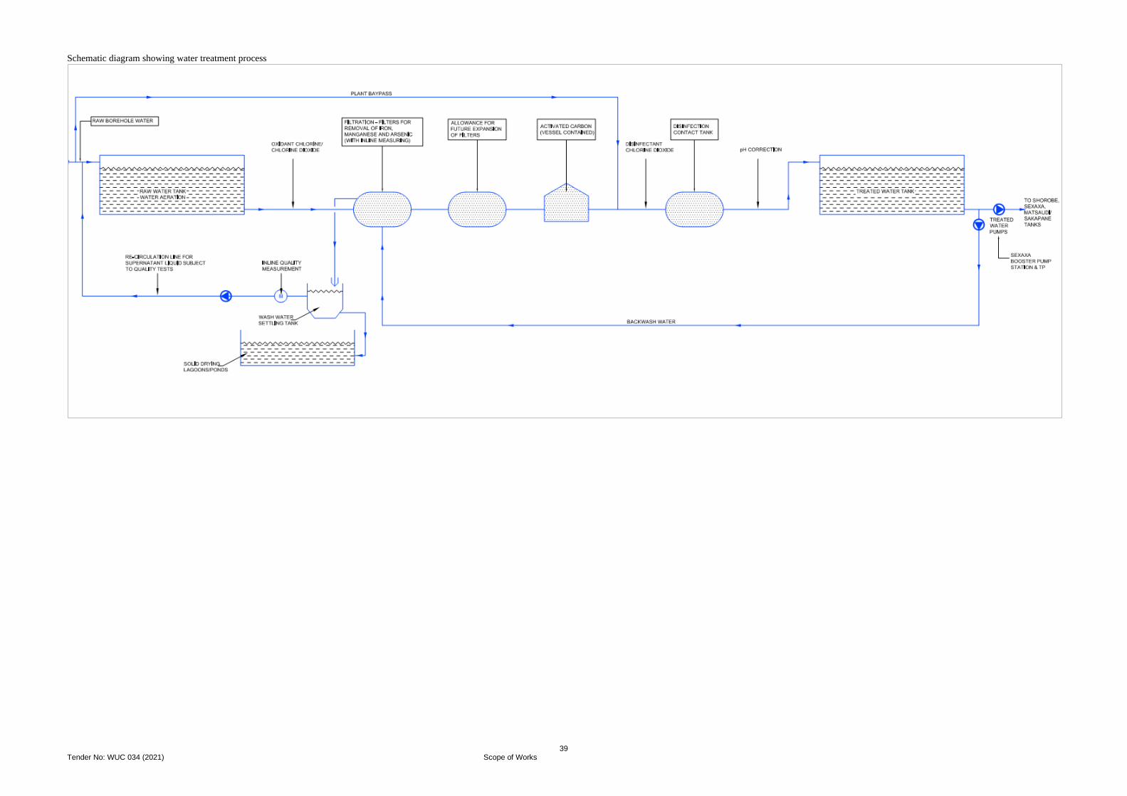
39 Tender No: WUC 034 (2021) Scope of Works
Schematic diagram showing water treatment process
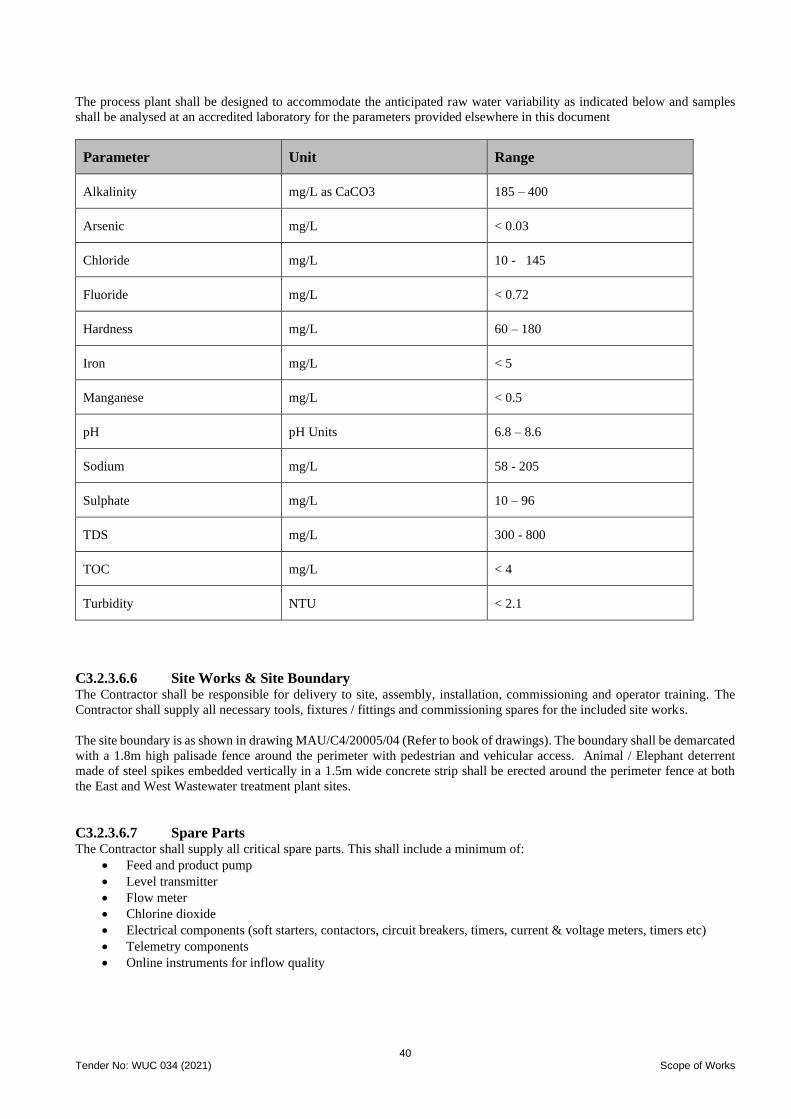
40 Tender No: WUC 034 (2021) Scope of Works
The process plant shall be designed to accommodate the anticipated raw water variability as indicated below and samples
shall be analysed at an accredited laboratory for the parameters provided elsewhere in this document
Parameter Unit Range
Alkalinity mg/L as CaCO3 185 – 400
Arsenic mg/L < 0.03
Chloride mg/L 10 - 145
Fluoride mg/L < 0.72
Hardness mg/L 60 – 180
Iron mg/L < 5
Manganese mg/L < 0.5
pH pH Units 6.8 – 8.6
Sodium mg/L 58 - 205
Sulphate mg/L 10 – 96
TDS mg/L 300 - 800
TOC mg/L < 4
Turbidity NTU < 2.1
C3.2.3.6.6 Site Works & Site Boundary
The Contractor shall be responsible for delivery to site, assembly, installation, commissioning and operator training. The
Contractor shall supply all necessary tools, fixtures / fittings and commissioning spares for the included site works.
The site boundary is as shown in drawing MAU/C4/20005/04 (Refer to book of drawings). The boundary shall be demarcated
with a 1.8m high palisade fence around the perimeter with pedestrian and vehicular access. Animal / Elephant deterrent
made of steel spikes embedded vertically in a 1.5m wide concrete strip shall be erected around the perimeter fence at both
the East and West Wastewater treatment plant sites.
C3.2.3.6.7 Spare Parts The Contractor shall supply all critical spare parts. This shall include a minimum of:
• Feed and product pump
• Level transmitter
• Flow meter
• Chlorine dioxide
• Electrical components (soft starters, contactors, circuit breakers, timers, current & voltage meters, timers etc)
• Telemetry components
• Online instruments for inflow quality
41 Tender No: WUC 034 (2021) Scope of Works
C3.2.3.6.8 Site Buildings Pump Station
The Contractor shall design, obtain all required statutory approvals, supply and deliver to site, erect, connect up, test on site,
commission, performance test, demonstrate and hand over in a clean and working order, complete infrastructure for the
permanent works. This shall include amongst others
• Pump house to accommodate all pumping units
• Booster pumps for Sexaxa (1 duty, 1 standby), Matsaudi & Sakapane (1 duty, 1 standby), and Shorobe (1 duty 1
standby) and Maun Disaneng North Tank (1 duty 1 standby)
• The MCC room must be separated from the pump to protect the MCC. However, a viewing window shall be
provided between the two rooms for operator use
• Other facilities and associated works
Operator office, Laboratory & Telemetry Control Room
The Contractor shall design, supply, construct, commission a laboratory building located at Sexaxa Water Treatment Works
site which shall be used for monitoring the performance of the treatment plant. The laboratory shall have a minimum floor
area of 300m2 and shall comprise of the following rooms as a minimum (refer to layout drawing provided in the book of
drawings):
• 2No Offices
• Laboratory Room
• Telemetry Control Room
• Common Room (Meeting Room)
• Kitchenette
• Male and Female Toilets
• Storeroom
• Minimum of 6No parking bays and an access road to the building starting from the Maun-Shorobe Road.
The contractor shall provide, amongst others, the following equipment for testing of the potable and reject water from the
treatment plant:
Potable water Reject Water
pH pH
Conductivity Conductivity
Multi meter for analysis of iron, manganese and arsenic COD meter
Chlorine dioxide meter Chlorine meter
Chlorine meter BOD meter
Multi meter for analysis of ammonia, phosphates,
sulphate nitrates
All buildings shall be designed for a 50year design live. The building design shall consider foundations, slabs, stability,
imposed conditions and materials.
Ablution Block
The Contractor shall be responsible for design and construction of an ablution facility for use by operators / casual labours at
the site. The ablution facility shall comprise of the following rooms:
• Female facilities
o Shower
o Toilet
o Changing area with locker and bench
• Male facilities
o Shower
o Toilet
o Changing area with locker and bench
Generator House
The Contractor shall be responsible for design and construction of a generator building with a footprint of not less than 60m2.
The generator building shall comprise of the following rooms:
• Generator room with minimum floor area of not less than 33m2
42 Tender No: WUC 034 (2021) Scope of Works
• Fuel storage room
• Storeroom
The building shall be louvred / have breeze bricks to allow for ventilation.
Guard House
The Contractor shall be responsible for design and construction of a guardhouse at the site entrance. The guardhouse shall
comprise of the following:
• Guard room
• Toilet
• Kitchenette
C3.2.3.6.9 Water Treatment Plant Tanks
The size of the raw water reservoir and treated water storage reservoir will need to be determined to provide the desired level
of resilience. For the raw water 12 hours retention is suggested but this will need to be reviewed by the Contractor. For the
treated water, since the treated water is pumped into further downstream storage tanks before being distributed, a smaller
reservoir is proposed. The number of days storage for chemicals should be determined, as well as the need for on-site power
generation.
The scope of works shall include:
• Feed storage tank: 12 hours storage (~1,200m3), epoxy coated galvanised steel, sectional panel tank
• Product storage: 6 hours storage (~600m3), epoxy coated galvanised steel, sectional panel tank. Note – the product
tank shall also function as disinfection contact tank.
C3.2.3.6.10 Water Treatment Plant Pumps The Contractor shall design, supply and construct the pumps for the treatment plant. The scope of works shall include:
• Duty / standby Feed pumps,
• Duty / standby product distribution pumps
• Backwash pumps
• Oxidant dosing pumps
• pH correction (feed pH correction) dosing pumps
• Wash water settling tank pumps, duty / standby
• All other pumps for the treatment plant
C3.2.3.6.11 Instrumentation & Control The Contractor shall provide a local Programmable Logic Controller (PLC) with control station for control of the
aeration/oxidation and filtration plant. The PLC shall include provision for fibre connection to the site wide control network.
Instrumentation shall include:
• Online aeration oxidation – Polarite filtration media analyser for product water monitoring (located upstream of
the product tank)
• Flowmeter for feed and product flows (located downstream of the feed and product tanks
• Level transmitters on the feed and product tanks
• pH analyser on aeration oxidation – Polarite filtration plant inlet
• Chlorine dioxide analysers on flow into and out of the product tank
The telemetry for the treatment plant shall incorporate all telemetry requirements specified under Section C3.2.3.11 and
shall be monitored together with the telemetry for the boreholes at the control room that will be located within the site.
C3.2.3.6.12 Access Road & Pedestrian Footways Access & Internal Road
The Contractor shall be responsible for design and construction of a 7m wide access road starting from the Maun – Shorobe
Road to the proposed site for treatment plant/booster pump station site. The road shall be linked with internal roads to the all-
site buildings (pump station building, operator & laboratory building, chlorination room, staff housing area, generator
buildings, etc) and to the water treatment plant building. A minimum of 6No covered parking bays shall be provided adjacent
43 Tender No: WUC 034 (2021) Scope of Works
to the operator & laboratory building. The access road should take the level of the Maun – Shorobe road and shall be provided
with 80mm thick, grey interlocking pavers, kerbing and drainage.
The contractor shall be responsible for obtaining the required approval from the Department of Roads and / or the North-
West District Council for the design of the access road between the Maun-Shorobe Road and the entrance to Sexaxa
Treatment Plant considering that the link is on the existing gravel road alignment to the Thamalakane River Lodge in the
area.
Pedestrian Footways
The water treatment plant site shall be connected by pedestrian footways to facilitate for easy and safe movement by operator
staff across the site. All areas shall therefore be connected by pedestrian footways (between treatment plant, buildings and
staff housing). Pedestrian pathways shall be 1.5m wide and shall be constructed from 60mm pavers (bevel edge, interlocking,
etc) or paving blocks as will be agreed with the Engineer. Pathways shall be properly restrained with kerbing.
C3.2.3.6.14 Documentation
The Contractor shall provide the following documentation:
• Piping and instrumentation Diagrams
• General Arrangements
• Single Line Diagrams
• Operations and Maintenance Manual
• Manufacturers Data Report
The number of copies of the documentation to be provided shall be in line with Section C3.2.3.13 – Time Schedule and
Reporting.
C3.2.3.7 Electrical Works
Under this contract, the power supply shall be required at the Sexaxa Treatment Plant site which is to be constructed on a
greenfield site. Power has been extended to the boreholes in the wellfield and some of the boreholes have been equipped
with electrically driven pump sets. The Contractor shall assess the adequacy of the power provided at the boreholes and
ensure that they are adequate for the pumps and accessories that are to be provided. Where replacement boreholes are
further from the existing power line, the Contractor shall engage with BPC for extension of the power line to the right
location.
For the electrical works, the contractor shall design, obtain all required statutory approvals, supply and deliver to site, erect,
connect up, test on-site, commission, performance test, demonstrate and hand over in a clean and in working order, the
complete electrical infrastructure for the water treatment plant and associated infrastructure and wellfield power supply. The
Contract scope shall include:
• Assess power requirements at each of the production boreholes in the wellfields and make the necessary
applications for upgrade of power where required
• Assess power requirements at the water treatment plant site and make the necessary applications for new power
connection
• Design and construct a suitable electrical reticulation to supply power to all components at the water treatment
plant site and the borehole components that require power supply to operate.
• Assess and provide a suitable electrical power back up system to meet the power supply demand for the major
components of the water treatment plant site to ensure their full function during power outages
• Assess and provide suitable backup power at the 7No production boreholes.
• Provide high mast lighting at the water treatment plant site. The high mast shall be capable of using solar / grid
power to operate
C3.2.3.8 Geotechnical Investigation
The Geotechnical Investigation report is available for review at the Clients office. This is a preliminary/conceptual report
and gives a general description of soil profiles in Maun and surrounding areas as well as available borrow pits. This report
was adequate for the conceptual designs; however, a more detailed geotechnical investigation is required for detailed designs
all in line with the works to be undertaken.
The preliminary geotechnical investigations carried out provided some information as outlined below:
44 Tender No: WUC 034 (2021) Scope of Works
The Maun Planning Area is predominantly Kalahari Sands overlying Calcretes which in turn overly Hardpan Calcretes and,
at greater depths, Silcretes. The thickness of the Kalahari Sand varies from 0.5m to over 6m but is generally about 2m thick
throughout the project area. The underlying Calcretes vary from finely grained Calcrete to hard Nodular Calcrete suitable for
road construction, generally lying in 1m to 3m thick layers. Hardpan Calcretes and Silcrete are generally found at depths of
more than 6m.
The collapse potential is likely to impact on the foundations structures and as such will need to be placed on a compacted
earth raft even at depths of +-3.0 metres. These platforms could be formed of blended sandy material or imported calcrete.
The Contractor shall identify qualifying sources of additional soil and /or calcrete for the works.
The Kalahari Sands will provide suitable bedding and backfill material and should be mostly stable in trench excavations,
preferably in dry seasons. In most areas, the soils are considered free draining material. This reduces the effect of heaving of
pipes as soil near the pipes become fluidised
Whilst Kalahari Sands are surprisingly strong when re-worked and compacted, they can offer considerable collapse potential
in their natural state. It is therefore important to identify the magnitude of any collapse to design suitable foundations for
structures. The collapse potential of in-situ Kalahari Sands typically ranges from 4 -12%.
Soil profiles
• The topsoil consists of silty fine sands or clayey fine sands varying in thickness from 100 mm to 900 mm
• The underlying Kalahari sands vary in thickness from 500 mm to about 6 metres
• The Kalahari sands are in turn underlain by powder calcretes, nodular calcretes and in some cases hardpan
calcretes or silcrete.
The storage tanks shall have their concrete raft foundations supported by a +1.0-metre-deep re-compacted soil raft
extending up to 10 metres beyond the edge of the tank. For safety reasons, deep trenches shall be shored, or the sides
battered to prevent collapse and possible loss of life
Borrow Pits and dump sites
The Contractor shall also be responsible to identify dump sites which include worked out borrow areas for surplus
excavated material and vegetation removed by site clearance.
The Contractor shall be responsible to identify borrow pit areas with suitable materials and quantification and shall be
responsible for securing and establishing the:
• Environmental authorisation and conditions of use
• Mining license from the Department of Geological Survey
• Access rights and mining leases from the responsible land boards
The Contractor shall be responsible for the rehabilitation of borrow areas, dump sites and access roads in accordance with
the requirements in the Environmental Management Plan and mining license conditions as may be applicable.
The position of some of the potential borrow pit areas are as shown in the table below.
Borrow Pits information
Location of
borrow pit (BP)
Coordinates Approximate
Area Material Grade
Y X
BP A -35308 2225377 200m x 250m G4/G5 2m working face – suitable for pipe
bedding
BP B -35624 2223906 200m x 300m G4/G5 2m working face – suitable for pipe
bedding
BP C -33956 2223880 200m x 200m G5/G6 2m working face – suitable for pipe
bedding
45 Tender No: WUC 034 (2021) Scope of Works
BP D -47060 2222638 200m x 300m G4/G5, suitable for pipe bedding or road
construction
BP E -51147 2220101 150m x 200m G6/G7, 2m working face, suitable for pipe bedding
BP F -51590 2210223 200m x 200m G5/G6 1m working face suitable for pipe bedding
BP G -49529 2204915 120m x 350m G7, 6m working face, suitable for pipe bedding
BP H -57803 2200643 300m x 300m G6, 2m working face, suitable for pipe bedding or
road construction
The geotechnical investigation conducted and reported in the conceptual design shall be treated as a general investigation
and as a result, further detailed investigation, for example at pump station and along pipe routes shall be conducted by the
Plant and Design - Build Contractor.
Contractor’s Liability
All information regarding sub-surface conditions, materials on the site, borrow areas and dump sites is provided in good faith,
for the Contractor’s convenience, as an indication of conditions likely to be encountered. Employer or Engineer accepts no
responsibility for the accuracy or comprehensiveness of the information or that the information is representative of the
conditions or materials likely to be encountered. Provision of such information shall not be regarded as in any way limiting,
or detracting from, the Contractor’s responsibility under the Contract. The Contractor shall be deemed to have satisfied
himself as to all surface conditions to be encountered on the Site of the Works and to have allowed accordingly in its tendered
amounts.
Before tendering, the Tenderer must form its own opinion by his independent enquiry and observation as to the character of
the strata through which the excavations are to be made and as to the level and amount of any water which he may have to
deal with when making the excavations or as to any other matter concerning the nature and conditions of the excavations
which he may be called upon to make. He shall be at liberty during the tender period, subject to prior approval of the
Employer, to excavate or drill in a manner to the satisfaction of the Engineer, any test holes or test boring at his own risk and
expense.
The Contract scope shall include
• carrying out necessary materials investigation work. The Materials Investigation Report shall include results/data,
analyses and interpretation of data and recommendations /comments on appropriate use of different materials for
pipeline, foundations, access structures and embankments construction amongst others. The report shall contain a
summary table depicting borrow pits and quarry location, indicating the offset chainage, GPS coordinates, estimated
quantities, type of soil, purpose in works, depth of topsoil and depth of overburden.
• identifying all areas/locations by coordinates. The use of GPS is recommended.
• giving due consideration to all environmental issues when searching for borrow pits and quarries for the project.
Laboratories
The Contractor shall have a laboratory onsite which they will manage as part of their scope. The Contractor shall arrange
with independent commercial laboratories as directed by the Engineer to undertake acceptance control testing which shall be
paid under Provisional Sum provided in the pricing schedules. The Contractor shall remain responsible for carrying out all
process control testing required by the Specifications.
C3.2.3.9 Topographical Survey & GIS Requirements
Topographical survey information used for the conceptual design was obtained from Department of Surveys and Mapping
(in the form of digital terrain model). The survey from DSM covered the Maun Buildable area but did not extend to the
wellfield area. The 2m contour interval survey from DSM has been deemed inadequate for design purposes.
46 Tender No: WUC 034 (2021) Scope of Works
Further on, a detailed topographical survey was undertaken under Contract 1. The survey covered some areas of interest
under Contract 4, i.e., Sexaxa Wellfield, Sexaxa & Matsaudi and part of the Maun to Shorobe Road. Raw survey data from
the LiDAR survey will be shared with the Bidders for processing and design of the scheme. The Bidders shall assess the
topographical survey information shared and identify all the gaps in this survey and submit the necessary method statements
and associated costs to bridge the gaps in the survey. All costs to close the gaps shall be included in the cost proposal.
The Contractor shall assess the suitability of the survey data, put measures to close any gaps and take ownership of the survey
for his design and construction activities. Any survey undertaken by the Contractor shall be as follows:
Survey Requirements
The Contractor shall use Real Time Kinematics (RTK) surveying methods to survey the features in the project areas.
Surveying shall be done in BTRS LO coordinate system.
• Surveys shall be attached/referenced to Botswana National Grid provided by Department of Surveys and
Mapping
• The Contractor shall perform site calibration at each site and submit the results of calibration to the Engineer
before commencement of survey works. The calibration computation summary shall be examined for
reasonable results in the horizontal scale, maximum vertical adjustment inclination, and the maximum
horizontal and vertical residuals.
• The Contractor shall be required to use at least four 3D points that can be used in calibration. Calibration points
shall be well distributed around the project area exterior.
• The contractor shall be required to state appropriate methods of survey under tree canopies and those methods
stated shall meet survey standards.
• Surveying shall be done as following
o The horizontal accuracy shall be at least ± 2 cm
o Vertical accuracy of at least ±5 cm.
Control and Permanent Markers
The main survey stations intended for control and future setting out shall be stable for at least 5 years after installation. Any
survey station located near infrastructure shall be located at least 3 metres from any infrastructure
Relationship to Grid
The survey shall be related to the national grid. A description of the grid system used shall be quoted on each survey plan:
Accuracy
The maximum error between permanent survey control stations shall not exceed 1 in 20,000. For distances between adjacent
permanent survey control stations of less than 300 metres, the maximum error should not be greater than ±15mm. (It may
not be possible to achieve this accuracy if ties to an existing control network is to be maintained.)
The height difference between any two points used as permanent ground markers or permanent benchmarks shall not be in
error by more than ± (12k) mm, where k is the distance in kilometres between the two points being considered, or ±5mm,
whichever is the greater. When control is related to GPS network using the real time corrections, relationship error can be
within ±20mm
Reporting
On completion of the fieldwork and adjustment, a comprehensive control report shall be prepared detailing the methods used
and checks applied, any problems encountered and demonstrating that the results achieved are in compliance with this
Specification.
This report shall be submitted in electronic format and shall include:
• The horizontal and vertical control framework maps
• Schedules of stations and benchmarks.
• Station and benchmark location diagrams.
• Problems encountered

47 Tender No: WUC 034 (2021) Scope of Works
C3.2.3.10 Land and Service Expropriation
The Contractor shall review at the early stages all details of the affected properties and services requiring expropriation. This
information shall be submitted to the Water Utilities Corporation at the earliest stage of works. In the event of none
submission of such drawings and information, the Engineer will assume that no properties & services are affected by the
works and claim that may arise due to non- submission of the information, have to be borne by the Contractor.
It will be the Contractor's responsibility to liaise with the respective service providers to ensure the nature and extent of
affected services is known and addressed before finalisation of the design. Similarly, it shall be the contractors’ responsibility
to liaise with the relevant Land Boards to ensure that affected people are consulted in time before finalisation of the design.
Compiled details of the expropriation of individual properties shall be submitted in Land Acquisition Form to the Water
Utilities Corporation bearing following information:
o Sketch of the property to be acquired shown on the pipeline route
o Measurements of expropriation, evaluating area and the size of remaining portion
o Offset achieved from structure(s), if any
o Location details, particulars of the plot and details of the Local Authority
o Land use details of property I properties for expropriation
o Confirmation whether the property Client has been contacted and consented
o Other relevant details
A provisional sum for land expropriation has provided in the provisional sums and shall be used at the discretion of the
Engineer and in consultation with relevant stakeholders, i.e., Tawana Landboard and the EIA Consultant.
C3.2.3.11 Telemetry and SCADA
The Project’s Telemetry & SCADA component objectives are to design, install, commission and set to work a system which
shall provide system operators and management the necessary information to efficiently manage the Maun Water Supply
Schemes comprising various components – boreholes, collector and distribution tanks, pump and water treatment plant. The
parameters to be monitored include motor pump sets and associate equipment status, water levels, flow rates, volumes,
pressures, water quality, site security and communications equipment status, power supply status and battery levels (at the
wellfield, water treatment plant and village tanks etc.).
The design, manufacture, factory testing, delivery to site, storage, installation, commissioning, site testing and handover of
the Telemetry and SCADA equipment shall be coordinated with other works within the Project to meet the Project’s overall
objectives.
At the Control Centre, the collected information shall be processed and displayed on LED Monitors in real time, enabling
automated operations as well as remote manual operations by the operators. It shall also be possible to retrieve historical data
and to analyse this information using trend analysis and other software tools. A typical site shall comprise a PLC and
output/input interface modules, stabilized power supply with standby battery, instrumentation devices, an HMI (for pumping
stations) and an Ethernet interface to the communications network to the relevant SCADA system.
The system shall be capable of local manual and remote (manual or automatic) control of pump operations after pump
protection interlocks are satisfied.
Local manual
• Pumps started manually from the MCC or the HMI.
Remote manual
• An operator at the Thamalakane Command Centre manually starts and stops the pumps from the SCADA
system by executing the appropriate commands
Remote automatic
• The pumps’ operations are under the control of the local PLC and SCADA dependent on the downstream
tank/reservoir levels
The Instrumentation and Control system shall be read as forming part of the electrical requirements and shall be integrated
jointly to determine the full requirements of the electrical and electronic scope of the work. All reasonable precautions shall

48 Tender No: WUC 034 (2021) Scope of Works
be taken in the design of equipment and of the works to ensure the safety of personnel concerned with the operation and
maintenance of the works.
Scope of Works
This section covers the scope in relation to telemetry, instrumentation and control system for water transmission, treatment
plant and associated works. The Contractor shall provide all additional instrumentation and control system to integrate
boreholes equipping, boreholes collector lines, booster station, water treatment plant including raw and clear water tanks with
the Thamalakane Command Centre in Maun. The Contractor shall make his own assessment of the existing
telemetry/instrumentation and control requirements.
The Contract scope shall include
• Design, supply, installation and commissioning of all PLC’s, input and output modules indicated for each site,
including the supply of all mounting accessories
• Design, supply, installation and commissioning of all instrumentation and sensing devices for each site including
the supply of all mounting accessories
• Design, supply, installation and commissioning of broadband radios at all indicated sites, including the supply of all
mounting accessories and the erection of antenna masts and any civil works associated with foundations, plinths,
etc. The design must comply with the Botswana’s Communications Regulatory Authority and Civil Aviation
Authority regulations. Broadband radios shall operate in the sub 6 GHz BOCRA licensed frequencies and offer
Ethernet networking interface.
• Design, install, configure and commission SCADA software at Control Centres and Thamalakane Command Centre.
The SCADA shall have, but not limited, to the following functionality:
o data acquisition and processing
o supervisory control
o alarm management
o system access control
o event logging
o historical data storage
o trending
o report generation
• Design, supply, installation and commissioning of all Local Area Networking equipment at all indicated sites.
• Design, supply, installation and commissioning of the Telemetry & SCADA, data processing and broadband
communications equipment at Nxaraga Treatment Plant telemetry centre including all associated power, data and
communications cabling and mounting accessories and the erection of antenna masts and any civil works associated
with foundations, plinths.
• Specification, supply, installation and commissioning of all instrumentation devices and ancillary equipment at
each indicated site.
• Design, supply, installation and commissioning of all equipment required to interface to existing or new
Instrumentation devices, including interposing relays, isolating devices, etc.
• Specification, supply and installation of cabling between all instrumentation devices and the PLC equipment at
each site, including new cable tray works where required.
• Design, supply, installation and commissioning of adequate power supplies and ancillary equipment at all
indicated sites.
• Power, communications and Local Area Network cabling, any site wiring relating to the installed equipment
shall also be specified, supplied, installed and terminated.
• Supply and installation of all equipment cabinets, weatherproof housing and mounting accessories needed to
meet the requirements of this Specification.
• Commissioning and site acceptance testing of the complete Telemetry & SCADA systems against approved
test schedules.
• Provision of Operation and Maintenance manuals, equipment technical manuals including factory and site
testing certificates and test results.
• Provision of training courses for 5No staff on the operation of the system.

49 Tender No: WUC 034 (2021) Scope of Works
• Provision of training courses for 5No staff on the maintenance of the system especially for carrying out routine
testing and first line repairs.
• Rectification of defects in any hardware, firmware or software item during the Defects Liability Period.
• Provision of spare parts for commissioning purposes and to support the Defects Liability Period.
• Provide computer hardware for monitoring at both water treatment plants:
o 2No Desktop computers with 2No 32-inch monitors
o 1No server
o 2No i7 or better laptops (Engineering staff)
o Software for process control and monitoring
o Anti-virus for all computers and laptops
o Layer 3 switch and router for ease of communication between the sites to be installed, configured and
commissioned
The Tenderer shall submit a Preliminary Design document where the overall system configuration is defined, general project
framework presented and schematics shall be provided. Following approval by the Engineer and Employer of the Preliminary
Design, the successful Tenderer shall submit a Detailed Design Document which will contain specifications and PID
drawings and a Functional Design Specification (FDS) document for approval by the Engineer and Employer. The document
shall specify in detail how the Telemetry & SCADA equipment configuration and software conform to the Specification and
shall include the following:
• Technical specifications for all equipment (hardware and software) supplied, including:
▪ Manufacturer’s model numbers
▪ Performance specifications
▪ Environmental specifications
▪ Power consumption
▪ Dimensions
▪ SCADA application software and licenses to be purchased
▪ Standard software packages
▪ Equipment specific software packages
• Detailed functions specifications for equipment at:
Sexaxa Treatment Plant Control Centre
▪ Plant monitoring and control facilities
▪ Formats of display pages
▪ Operator keyboard facilities
▪ Command functions
▪ Alarm handling procedures
▪ System housekeeping
▪ Power up/down procedures
▪ Data storage and retrieval
▪ System security
▪ Reconfiguring of facilities
Remote sites
▪ Local display and control facilities
▪ Configuration and I/O capacity
▪ Use of portable field equipment
▪ Reconfiguring of facilities
• Outline installation drawings for the complete system including:
▪ System configuration schematic drawings
▪ Field cable termination schedule for each site
▪ Outline mechanical assembly drawings for each item of equipment showing leading dimensions, mounting
details, etc.
▪ Outline installation details and loop diagrams for instrumentation devices
▪ Outline installation drawings for radio communications equipment and antennae
▪ Outline installation drawings for power supplies, AC and DC, for the sites
▪ Bill of Quantities of the hardware and software.
Once approved by the Engineer and Employer the FDS shall become the Contract design specification
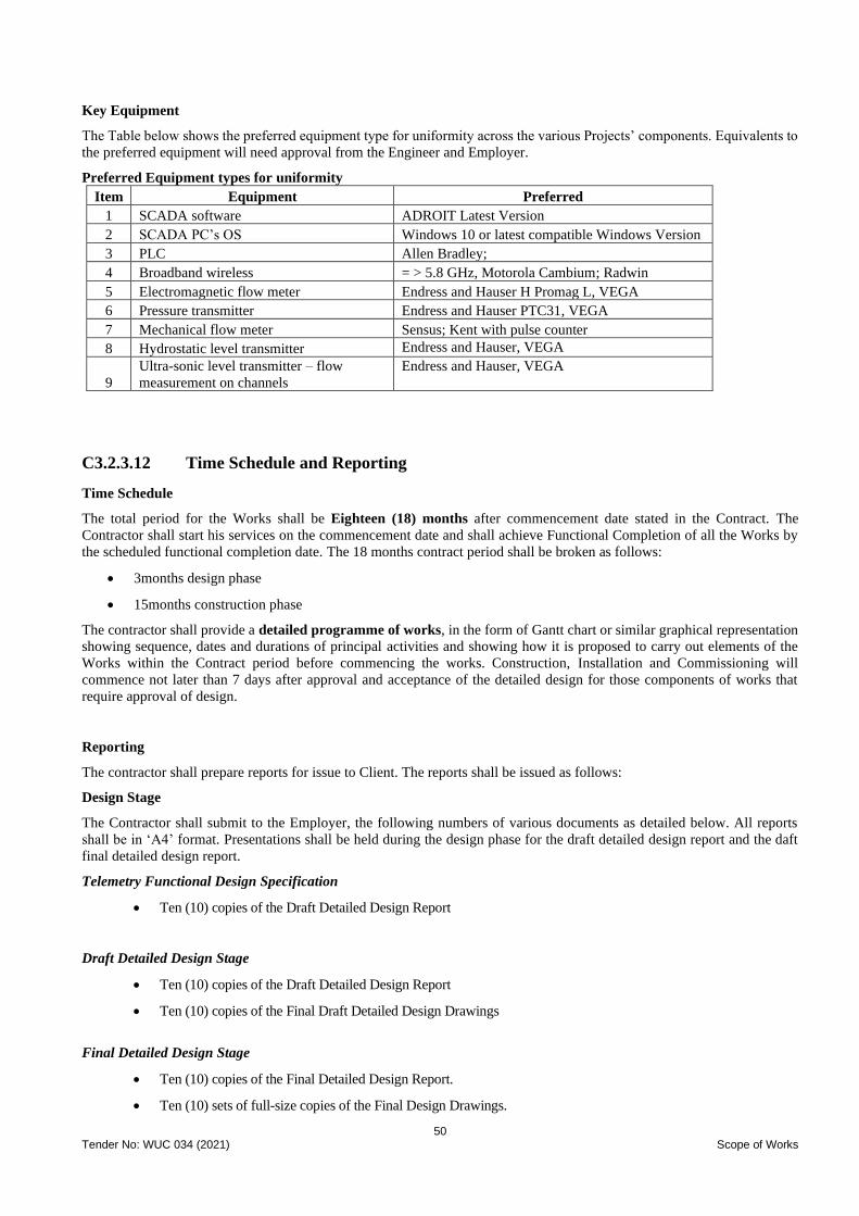
50 Tender No: WUC 034 (2021) Scope of Works
Key Equipment
The Table below shows the preferred equipment type for uniformity across the various Projects’ components. Equivalents to
the preferred equipment will need approval from the Engineer and Employer.
Preferred Equipment types for uniformity
Item Equipment Preferred
1 SCADA software ADROIT Latest Version
2 SCADA PC’s OS Windows 10 or latest compatible Windows Version
3 PLC Allen Bradley;
4 Broadband wireless = > 5.8 GHz, Motorola Cambium; Radwin
5 Electromagnetic flow meter Endress and Hauser H Promag L, VEGA
6 Pressure transmitter Endress and Hauser PTC31, VEGA
7 Mechanical flow meter Sensus; Kent with pulse counter
8 Hydrostatic level transmitter Endress and Hauser, VEGA
9
Ultra-sonic level transmitter – flow
measurement on channels
Endress and Hauser, VEGA
C3.2.3.12 Time Schedule and Reporting
Time Schedule
The total period for the Works shall be Eighteen (18) months after commencement date stated in the Contract. The
Contractor shall start his services on the commencement date and shall achieve Functional Completion of all the Works by
the scheduled functional completion date. The 18 months contract period shall be broken as follows:
• 3months design phase
• 15months construction phase
The contractor shall provide a detailed programme of works, in the form of Gantt chart or similar graphical representation
showing sequence, dates and durations of principal activities and showing how it is proposed to carry out elements of the
Works within the Contract period before commencing the works. Construction, Installation and Commissioning will
commence not later than 7 days after approval and acceptance of the detailed design for those components of works that
require approval of design.
Reporting
The contractor shall prepare reports for issue to Client. The reports shall be issued as follows:
Design Stage
The Contractor shall submit to the Employer, the following numbers of various documents as detailed below. All reports
shall be in ‘A4’ format. Presentations shall be held during the design phase for the draft detailed design report and the daft
final detailed design report.
Telemetry Functional Design Specification
• Ten (10) copies of the Draft Detailed Design Report
Draft Detailed Design Stage
• Ten (10) copies of the Draft Detailed Design Report
• Ten (10) copies of the Final Draft Detailed Design Drawings
Final Detailed Design Stage
• Ten (10) copies of the Final Detailed Design Report.
• Ten (10) sets of full-size copies of the Final Design Drawings.

51 Tender No: WUC 034 (2021) Scope of Works
• Complete set of final Drawings in reproducible format for Employer’s approval as well as
electronically.
Construction Stage
The Contractor shall prepare and submit to the Employer’s Representative ten (10) copies of Construction Drawings for
whole of the Works defined in this tender. Final Construction Drawings shall be prepared in reproducible form on approved
permanent material and electronically. The drawings shall be dimensioned in metric units and produced on “A1” metric
format. These drawings shall typically include but not be limited to:
Schematic Layout Drawings for water treatment plant
Detailed Design Drawings – borehole equipping
Detailed components of the water treatment plant
Plans and longitudinal sections of the pipelines, pipe trenching and bedding details,
Construction drawings for all project components including details of pipe connections
Details of road and river crossings of pipelines
Details of access road to water treatment plant site
Various chamber details and connections for different types of fittings,
Auxiliary items such as anchor and thrust blocks, marker posts, fences etc.
Specialist Drawings for the water treatment plant components and accessories as required by the
Employer
Detail drawings of operator office & laboratory buildings, guard house, chemical storage building &
workshop and standby generator house
Auxiliary items such as anchor and thrust blocks, marker posts, fences etc.
Construction drawings for all project components including details of pipe connections
Control Drawings
Switch, Starter and Control Panel Drawings
Electrical installation drawings
Mechanical installations drawings
Telemetry installation drawings
Progress Reports
The Contractor shall prepare Monthly and quarterly progress reports and submit to the Engineer 15 copies of the same. The
first report shall cover the period up to the first month following the award of the contract. Reporting shall continue until the
Contractor has completed all the Works, which is known to be outstanding at the completion date in the Taking-Over –
Certificate for the Works. Each report shall include:
• Charts showing the actual progress of the works with respect to the planned progress as per the programme of
the works approved by the Employer’s Representative. Detailed descriptions of progress, including each stage
of design and construction, Contractor’s Equipment, procurement, manufacture, delivery to site, construction,
erection and performance testing. These should also include the statements for each sub-contractor and
nominated sub-contractors (if any). The details of any events or circumstances, which may jeopardize the
completion of the Works in accordance with the Contract, and the measures being (or to be) adopted to
overcome these shall be highlighted
• Colour photographs showing the status of the works and progress on site shall be taken monthly and shall cover
such extent and parts of the works as to record the progress of the works or to provide a record of construction,
• The report on Contractor’s personnel and equipment
• Copies of Quality Assurance Documents, test results and test certificates of the Materials
• List of Notices of Claims, given by Contractor / Employer
• Safety statistics, including details of any hazardous incidents and activities relating to environmental aspects
and public inconveniences

52 Tender No: WUC 034 (2021) Scope of Works
• Payment schedule
Construction, Installation and Commissioning
The contractor is required to state
• The origin or the manufacturer of the scheme components and expected delivery periods.
• The source of spare parts, consumables and their expected delivery period from the date of order.
• During the period of commissioning, the Contractor shall also train the Employer’s staff in the routine
operations and maintenance of the boreholes, water treatment plant and booster stations.
• The Contractor shall commission and operate the water treatment plant for 6months (Contractor shall indicate
the cost of operating the entire scheme). During operation of the scheme, the Contractor shall work closely with
chosen representatives from the Client / WUC who shall take over operation of the scheme post the 6months
period.
• The Commissioning of the scheme shall be witnessed by the Employer’s Representative (The Engineer)
• The contractor must provide initial spare parts that are not covered by the guarantee for a period of twelve (12)
months and consumables for six (6) months during maintenance of the water treatment plant.
• Contractor shall provide the Operation and Maintenance Manuals before Commissioning Stage.
The following will be required as part of handover:
(a) Six (6) sets of As Built Drawings (Civil, Mechanical, Electrical and Telemetry and SCADA System)
(b) Six (6) sets of As Built Drawings for the Treatment Plant and all associated works
(c) Six (6) sets of Operation and Maintenance Manuals
As-Built Data Format
As-built layouts shall be submitted in CAD drawings (latest version), ESRI File Geodatabase (Using WUC Schema) and
PDFs. The warrant period of the data collected in the project shall be 12 months, the warrant shall include but not limited to:
• Corrections
• Quality
• Omissions
Progress Meetings
The Employer’s Representative (The Engineer) will convene the project progress meetings and an authorised representative
of the Contractor who is fully familiar with content of the works, and the progress on site, shall attend site meetings when
requested by the Employer’s Representative with the Contractor as follows: -
• Design meetings that will be held as follows:
o First progress meeting: - within 2 weeks after the submission of the Draft Detailed Design Report.
o Second progress meeting- within 2 weeks after the submission of the Final Detailed Design Report.
• Construction meetings will be held as follows:
o Monthly progress meetings will be held monthly from the commencement of the project or at such intervals as
will be determined by the Engineer
o Quarterly meetings will be held every quarter. Monthly progress meetings will not be held on the month that the
quarterly meeting is held
o Technical meetings will be held monthly or at such intervals as will be determined by the Engineer

53 Tender No: WUC 034 (2021) Scope of Works
Minutes of meeting proceedings will be taken by the Engineer and be circulated to members of the committee one week at
the latest before the next meeting.
Operation of the Scheme and Training of Employer Staff
To ascertain that the contractor hands over to the Employer a functional scheme in accordance with the Client Requirements,
the contractor shall operate and maintain the water treatment plant for 6 months. The contractor shall train the Employer’s
staff on operation of all scheme components to allow for a seamless handover of operation upon completion of the project.
The contractor shall also prepare an electronic asset register for issue to the Client at the end of the project. This asset register
will include all components of the scheme, their make, model, dates for when they were put online and the recommended
service dates. This register shall match the components specification details as contained in the operation and maintenance
manuals.
C3.2.3.13 Design Standards
All design of structures, equipment, machinery, pipes and fittings, etc. for water supply will conform to the relevant codes,
practices and specifications in practice. Wherever necessary, modifications or improvements shall be made to suit the local
conditions and requirements as well as the use of Contractor’s experience. The applicable standards, although not exhaustive,
are listed below:
Water
All design of pipes, fittings, structures, equipment, and machinery for water supply will conform to the relevant codes,
practices and specifications in practice.
The standards used to design the water supply scheme and analysis are:
• Water Supply Design Manual Review (2008)
• Water Utilities Corporation Standards (1995)
• Botswana Standard, BOS 32:2015 - Drinking Water Specification
• BOS ISO 5667–3: 2003 Water quality – Sampling – Part 1: Guidance on the preservation and handling of water
samples
• BOS ISO 5667–11: 2009 Water quality–Sampling - Part 11: Guidance on sampling of groundwater
• In instances where such standards are not complete, reference shall be made to other relevant standards.
Telemetry
Unless otherwise specified, the whole of the Works shall comply with the requirements of all relevant local regulatory bodies
in the Republic of Botswana and their standards current at the time of tender or an equivalent British, SABS or International
Standards approved by the Engineer, including in particular the following:
• Water Supply Design Manual Review (2008)
• WUC SCADA Standards and Project Planning (2010)
• BOCRA Telecommunications Regulatory Policy
• Electricity Supply Regulations 1988 - Botswana
• IET Electrical wiring regulations (BS7671:2008)
• Fire detection and alarm systems- BS 5839 Part 1: 1988
• Special requirements of the Electricity Authority
• Botswana Telecommunications Act of 1996
• Botswana Power Corporation (BPC) Standard Requirements for Distribution Systems (SRDS)

54 Tender No: WUC 034 (2021) Scope of Works
• ITU Standards on Radio Frequency Interference Suppression
• ISO Standards on equipment manufacture and instrument calibrations
• ISA Standards on nomenclature
Mechanical
The designs of the mechanical works shall be undertaken in compliance with national and international standards. Some of
the applicable key standards include the following:
• SANS 8849: Small Craft - Electrically operated direct-current bilge pumps
• SANS 60335: Household pump and electrical appliances
• SANS 54511: Air conditioning, liquid chilling and heat pump
• SANS 5151: Non-ducted air conditioners and heat pumps - Testing and rating for performance
• SANS 13253: Ducted air-conditioners and air-to-air heat pumps - Testing and rating for performance
• SANS 1125: Room air conditioners and heat pumps
• SANS 9906: Rotodynamic pumps
• SANS 1700: Fasteners
• SANS 7005-1: Metallic flanges Part 1: Steel flanges
• SANS 7005-2: Metallic flanges Part 2: Cast iron flanges
• BS 4999: Part 101, 105, 108, 109, 112 & 141: Rotating electrical machines
• BS 5000 Parts 10 or 11 and 17: Rotating Electrical Machines
• SABS 1109-1: Pipe threads where pressure-tight joints are made on the threads Part 1: Dimensions, tolerances
and designation
Electrical
Designs for the electrical works shall be undertaken in accordance with the national and international standards of which
some of the key standards are listed below:
• SANS 10142-1: 2006 – Wiring Code
• IET Electrical wiring regulations (BS7671:2008)

55 Tender No: WUC 034 (2021) Project Specification
WATER UTILITIES CORPORATION
CONTRACT PART 3
SCOPE OF WORK
PROJECT SPECIFICATIONS
A WORKS CONTRACT FOR THE PROCUREMENT OF CONTRACTORS
FOR THE DESIGN, SUPPLY AND BUILD OF MAUN SATELLITE VILLAGES BULK WATER
SUPPLY INCLUDING WATER TREATMENT PLANT AT SEXAXA
TENDER REF NO: WUC 034 (2021)
PART 3: Project Specifications
PS1.1 Project Area
The project is undertaken in the Satellite Villages of Sexaxa, Matsaudi, Sakapane and Shorobe just outside the Maun water
distribution network. These villages had a combined population of 2152 as confirmed by the 2011 population census and are
situated north-east of Maun within a 40km radius. Maun is the administrative capital of the North-West District (NWD) and
is the commercial centre for north-western part of Botswana. The village is about 900 kilometres North West of the capital
city of Gaborone and 500 kilometres west of the second city of Francistown. It is approximately 400 kilometres from Shakawe
and about 200 kilometres from Gumare.
PS2 Use of Site The lands and other places outside the Site shall not be used except with the approval of the Client Representative.
The Contractor shall at any time remove any vehicle, wagon, barge or vessel or any other obstruction within his control that
may be required to be moved by the Client Representative for any purpose. The Contractor shall move such obstruction
promptly on instruction being given and at his own cost unless the Client Representative shall decide otherwise. The
Contractor shall maintain access for the inspection, operation and maintenance of any of the Employer's Plant or Work, which
lies within the Site or elsewhere. The Contractor shall not use any portion of the Site for any purpose not connected with the
Works unless the prior written permission of the Client Representative has been obtained.
The Contractor's employees will not be permitted to enter any of the Employer's buildings or lands or sites under the control
of other Contractors or the Contractor Design Engineers, except with the written permission of the Client Representative
which will be given when necessary for the execution of the Works. The Contractor shall warn his employees that any man
found within such buildings or sites without authority is liable to be removed from the Works in accordance with the
provisions of Clause 6.9 of the Conditions of Contract.
PS2.1 Protection of Site against Flooding
It is the Contractor’s responsibility to protect the Works against possible flooding and water ingress. Measures that the
Contractor may wish to take for dewatering and protection against flooding must be incorporated into the applicable rates in
the Schedules of Quantities. Protection against wash away of any material or flood damage to any of the Works or planted
areas shall be the responsibility of the Contractor. Failure to protect the Works against flooding shall not entitle the Contractor
to a full claim for consequential damages due to abnormal rain.
PS2.2 Open Trenches
Trenches may not be left open during the Contractor’s holidays and shall be safeguarded at all times from danger to the
public. Safe trench-crossings shall be provided at all intersections with accesses to properties and with public roads and paths.
The length of trench left open at any one time may be restricted by the Engineer, should he consider such restriction to be in
the interests of public safety.
PS2.3 Finishing and Tidying and Site Maintenance
During the progress of the work and upon its completion, the site of the works shall be kept and left in a clean and orderly
condition. The contractor shall always store materials and equipment for which he is responsible in an orderly manner and
conducive environment and shall keep the site free from debris and obstruction.
The existing roads to the site shall be kept free from any stones, rubble or dirt brought onto the roads by the Contractor’s
Construction Vehicles. Damages done to the road by the Contractor’s Construction Vehicles shall be repaired immediately.
Progressive and systematic finishing and tidying will form an essential part of this contract. On no account must spoil, rubble,

56 Tender No: WUC 034 (2021) Project Specification
materials, equipment or unfinished operations be allowed to accumulate in such a manner as to impede the activities of others
unnecessarily and in the event of this occurring, the Employer shall have the right to withhold payment for as long as may be
necessary in respect of the relevant works in the area(s) concerned without thereby prejudicing the rights of others to institute
claims against the contractor on the ground of unnecessary obstruction.
Finishing and tidying must not be deferred to the end of the contract. The works will not be certified as complete until the
whole of the works, including all finishing and tidying has been fully completed to the satisfaction of the Engineer.
PS3 Construction Programme
PS3.1 Time for Completion
The whole of the Works to be constructed under this Contract shall be completed within the time stated in the appendix to
Tender, i.e., within a period of 18 months.
PS3.2 Programme of Works
The Contractor shall in accordance with Clause 8.3 of the Conditions of Contract, and before commencing work on Site,
submit to the Engineer a fully detailed programme indicating the order of procedure and method by which he proposes to
carry out the construction and completion of the Works, and particulars of the organisation and staff proposed to direct and
administer the contract.
The programme shall be a typical operational level programme which shows sufficient detail of sections of the works, tasks
and sub-tasks, resource levelling and time units to enable an accurate assessment of progress to be made to within a time
period not exceeding one week. All activities to be performed by Sub-Contractors shall be shown separately from those
performed by the Contractor. The contractor shall clearly show in the programme the time frame when the services installation
activities such as telecommunication services, street lighting and power supply services shall be undertaken.
The programme submitted shall be in the form of a GANTT Bar Chart showing the critical path as a clearly identifiable heavy
line on the construction programme. If the Clause 8.3 programme or any subsequent revisions is not delivered on time, the
Engineer shall be entitled to withhold on any Payment Certificate which may be due such sums as the Engineer considers
appropriate under the Preliminary and General items. Particular attention must be paid to Clause 8.5 - Works Executed by
Other Contractor’s and the construction and programming of the Works required with the other Contractor’s. Allowance
must be made in the Contractors programme for any reasonable interference, working out of sequence and delay which the
contractor may suffer as a result of working with other Contractors.
PS4 Site Facilities Available
PS4.1 Water Supply
The Contractor shall be solely responsible for the procurement, operation and maintenance of a water supply adequate in
quality and quantity to meet his obligations under the Contract. The Contractor shall be responsible for the procurement,
conveyance, etc. of water for construction purposes under the Contract. The rates entered in the Schedule of Quantities shall
be deemed to include for all obligations for the location, procurement and maintenance of adequate water and shall be deemed
to include for all costs in association therewith.
PS4.2 Electricity Supply
The Contractor shall make his own arrangements for power supplies and shall be solely responsible for the location,
procurement and maintenance of a power supply, adequate to meet his obligations under the Contract. The rates entered in
the Schedule of Quantities shall be deemed to include for all obligations for the location, procurement and maintenance of
power supplies and shall be deemed to include for all costs in association therewith.
PS4.3 Sewer Connection
The Contractor shall make his own arrangements to provide sewage handling facilities which shall be in accordance with the
requirements of the relevant department of the North-West District Council. The rates entered in the Schedule of Quantities
shall be deemed to include for all obligations for the location, procurement and maintenance of sewerage disposal and shall
be deemed to include for all costs in association therewith.
PS4.4 Location of Yards and Offices
The Contractor will make his own arrangements as to a suitable site for their yards and offices.
PS4.5 Accommodation

57 Tender No: WUC 034 (2021) Project Specification
The Contractor shall be responsible for the accommodation and transport of all his personnel.
PS5 Site Facilities Required
PS 5.1 Telephones and Communications
The Contractor shall be responsible for obtaining one “fast connect” telephone lines and a PABX system for use at the
Engineers office with 6No extensions to offices of the Engineer's staff. The telephone line shall be independent of the
Contractor's telephone lines. The line will be allocated as dedicated telephone line and one line for a fax machine.
Within fourteen days of the date of issue of the Acceptance of Offer, the Contractor shall provide 2 No. new smart business
cellular telephones with chargers and covers, inclusive of thirty-months (30) (or as directed by the Engineer) air and data
contracts, for use by the Engineer staff. All cellular phone calls will be reimbursed through the Contract. However, if the
Contractor fails to provide the site offices within the period stipulated, then the Contractor shall bear the cost of local cellular
phone calls in the interim period until the site offices and the telephone facilities are made available to the Engineer. After
the permanent telephone system is installed, the cost of all telephone calls shall be reimbursed through the Contract.
The Contractor shall also provide 6No smart cell phones for eighteen-month (18) (or as directed by the Engineer) with voice
and data contracts, and 14No smart cell phone sets for prepaid telephone for use by the Engineer staff during the contract.
PS 5.2 Sanitation
The Contractor shall provide adequate sanitation and refuse collection and disposal facilities complying with the laws of
Botswana and local bye-laws for all houses, offices, workshops, etc. erected on the sites, all to the satisfaction of the
Employer’s representative. The Contractor shall warn Contractor’s personnel and Subcontractors that any employee found
fouling the Site would be removed from the Site immediately in accordance with the provisions of Sub-Clause 6.9 of the
Conditions of Contract.
PS 5.3 First Aid and Medical Services
The Contractor shall provide and maintain in operating condition, all equipment necessary to render first aid in case of
accidents, or other emergencies. This equipment shall be kept in readiness at the sites of the Works, at camps, the Engineer’s
site offices and wherever the Contractor’s personnel may regularly live and work. The Contractor shall ensure that there are
persons available at all such places with knowledge of basic first aid procedures.
PS 5.4 Site Office and Staff for the Engineer
The Contractor shall provide, equip and maintain in full working order fully furnished and serviced offices for the sole use
Engineer, their assistants and other persons authorised by him. The Contractor shall, if required, be responsible for obtaining
the approval from the local authorities for the location of the office complexes.
The site office shall be complete with furniture and equipment, as detailed in Schedule 1.2 of the Project Specification. All
computer equipment and software, as listed in Schedule 1.2, and all furniture and equipment shall be returned to the Employer
at the end of the Defects Notification Period or earlier at the Employer’s discretion for use as directed by him. The computer
equipment and software shall become the property of the Employer at the end of the Defects Notification Period or at the
discretion of the Engineer.
The site offices shall be handed over to the Engineer only when ready for occupation, with furniture, equipment, air
conditioning, computer hardware and software, telephones, water and power all provided as specified and to the satisfaction
of the Engineer.
The net floor area of the office shall not be less than 350m2 and shall be able to house at least twenty-four personnel, must
have toilet, conference room, kitchen, reception, server room and storage room as a minimum. The offices shall be portable
type office, e.g., Kwikjack / Teams type offices and shall be constructed from new, strong, durable and weatherproof
materials, with walls, ceilings and floors adequately insulated against heat and cold, mosquito proofed and suitably painted
inside and out. The portable office can be aggregated into one unit or provided as separate units but meeting the office and
space requirements (number of offices and size) as specified.
All office rooms shall be provided with through ventilation, two-number twin electric tube lights with separate switches,
overhead fan, air-conditioning unit of adequate capacity and three power points. All windows shall be fitted with burglar bars
and doors fitted with good quality locks to Engineer’s approval.
Flooring is to be 600mm by 600m ceramic or porcelain tiles to the Engineer’s approval. 2m x 2m soft board panels shall be
provided for display purposes in each office. Additional soft board material shall be provided in the Conference room and in

58 Tender No: WUC 034 (2021) Project Specification
other rooms where directed for mounting maps and other charts. A 230 Volt continuous electrical power supply shall be
provided for the office, having sufficient capacity for all normal lighting, air-conditioning and other equipment provided.
The site office layout shall be as agreed with the Engineer and shall include the following:
• Offices of various sizes to be agreed by the Engineer. Minimum 12No offices
• A reception area with a visitor sitting area
• Conference room to accommodate a minimum of 30 persons
• Separate lockable toilet facilities for staff (male and female)
• A kitchen with hot and cold water and a minimum of three power points
• A secure storeroom
• Isolation room
• Outside sitting area under a shaded cover with chairs and tables for use by staff
• Carports for 24 vehicles
A full-time registry clerk/receptionist, who shall be able to read, write and speak the English language and be in possession
of appropriate training and at least two years’ experience, shall be provided at the office. A messenger/driver and cleaner/tea-
lady, both fluent in the English language, shall be provided on a full-time basis at the Engineer’s site office.
At the end of the Defects Notification Period or at the discretion of the Engineer, the porta cabin shall be moved to a location
within 300km radius as will be directed by the Engineer for use by the Employer as offices.
PS 5.5 Time for Erection of and Method of Payment for the Office Complex for the Engineer's Staff
The Contractor shall, within 56 days of date of the Acceptance of Offer, erect, equip the Engineer's site office, and provide
staff in accordance with the requirements of Clause PS 5.4. The Contractor shall bear all expenses incurred by the Employer
due to any failure of the Contractor to complete and hand over to the Engineer the office, furniture and equipment required
within the stipulated period. In the absence of and until the erection of the established site office, the Contractor shall provide
a caravan or caravans or other acceptable temporary office arrangements at a site to be approved by the Engineer.
PS 5.6 Survey Instruments and Chainmen for the Engineer's Staff
The Contractor shall provide and maintain in first class working order, for the sole use of the Engineer's staff for the duration
of the Contract, the survey instruments is detailed in Schedule 1.3 of the Project Specification. The equipment shall be
complete with all accessories, staging, moulds, templates and profiles, plumb-bobs, lines, pegs, pins, hammers, nails, strings,
paint, brushes and other such articles required by the Employer’s representative for inspection, checking of setting out and
measurement of the Works. This equipment shall be supplied within 28 days of date of the Letter of Acceptance and shall be
taken over by the Client on the issue of the Taking-Over Certificate for the whole of the Works or at the discretion of the
Engineer. The Contractor shall provide a replacement survey instrument when the purchased instrument is out being serviced.
The Contractor shall provide the services of six (6) experienced chainmen to support the surveyors engaged by the Engineer.
Payment for chainmen shall be calculated on a man-month basis.
PS 5.7 Vehicles and Drivers for the Engineer's Staff
The Contractor shall provide and maintain eight (8) new double cabin vehicles, eight (8) new single cabin vehicles and a
7seater vehicle as detailed under Schedule 1.4. These vehicles shall be for the sole use of the Engineer's and Client staff for
the duration of the Contract. The vehicles shall be handed over to the Engineer within 35 days of the date of the Acceptance
of Offer or at the instruction of the engineer. The vehicles shall be new from the suppliers and shall be comprehensively
insured including passenger insurance. The Contractor shall be responsible for the provision of fuel and lubricants, and for
maintaining the vehicles in a fully roadworthy serviceable condition and the cost shall be allowed for this. The Contractor
shall arrange for the vehicles to be maintained by the dealer on a regular basis. The Contractor shall provide a replacement
vehicle of similar standard whenever a vehicle supplied under this Clause is not available for use because it is unserviceable
or because of regular maintenance taking more than eight hours in any vehicle-week. The Contractor shall be responsible for
maintaining the above-mentioned insurance for the vehicles throughout the duration of the Contract.
Before the delivery of the new vehicles and/or whenever instructed by the Engineer, the Contractor shall provide one double
cab hire vehicle. An item shall be allowed for under Schedule 1 of this contract for the provision of such a vehicle. If the new
vehicles are not delivered within the stipulated time, the Contractor shall provide hire vehicles of equivalent number and type
until the new vehicles are supplied. No additional payment will be due in respect of such hire vehicles. The Contractor shall
provide fuel and lubricants and maintain the hire vehicles in a fully roadworthy condition.
The Contractor shall price the full value of the new vehicles and state the residual value of the vehicle at the Time for
Completion under appropriate items in the Bill of Quantities. The Employer may keep the vehicles or nominate a person to
59 Tender No: WUC 034 (2021) Project Specification
purchase the vehicle on payment of the priced residual value to the Employer. If the Employer elects not to keep the vehicles
or nominate a person to purchase such vehicle, then the Contractor shall purchase the vehicles from the Employer on the
payment of the absolute amount quoted as the residual value. All but one of the vehicles shall be released for purchase at the
end of the construction or at the discretion of the Employer’s Representative (The Engineer). The remaining vehicle shall be
returned to the Client a month later. Prior to reverting to the Client, the vehicles shall be fully serviced by the Contractor and
proof of service given to the Engineer.
In addition to the new vehicles described above, the Contractor shall provide hired vehicles on a short-term basis as and when
required by the Engineer. The Contractor shall be responsible for all necessary insurance, collision damage waiver, etc. for
the vehicles and shall be responsible for the provision of fuel and lubricants. A Provisional Sum has been included for the
hiring of these vehicles.
Payment for operating and maintaining the vehicles shall be made in the following manner:
• by vehicle-month rate which shall include for the first 7000 km per vehicle-month.
• by an additional rate per vehicle-kilometre, over 7000 km per vehicle-month.
The vehicle-kilometres payable each month for each vehicle shall be determined and to the approval of the engineer. If the
resulting vehicle – kilometre figure is negative, no payment shall be made for vehicle-kilometres for that vehicle.
The Engineer shall be in full control of and shall employ his discretion in the use of vehicles supplied under this Clause. All
duplicate keys shall be delivered to the Engineer when handing over the vehicles.
PS 5.8 Housing for the Engineer's Supervising Staff
The Contractor shall provide, furnish, equip and maintain for the duration of the Contract, rented accommodation close to
the Site for the sole use of the Engineer's resident site staff.
The accommodation shall be to the Engineer's approval. The accommodation shall be on a securely walled property. Such
accommodation shall be provided within the period stated in Clause PS5.9. Provision for temporary suitable hotel
accommodation shall be made if arrangements relating to the permanent accommodation are delayed for any reason. The
cost of the temporary accommodation shall only be reimbursed through the Contract for the period ending 30 calendar days
from the date of the Letter of Acceptance. Thereafter the cost of temporary accommodation shall be borne by the Contractor.
The rented accommodation shall be Type 1 house, and Type 2 house as per the following minimum acceptable specifications:-
Type 1 house (3Nos) shall comprise.
• minimum 3 bedrooms with one bedroom complete with toilet facilities (i.e., ensuite)
• bathroom
• toilet
• lounge
• dining room
• fully fitted kitchen
• carport / garage (minimum 2No covered carport)
• accommodation for a domestic servant.
• wall fenced and gated
• security alarm
Type 2 house (14Nos) shall comprise.
• minimum 2 bedrooms
• lounge
• fully fitted kitchen
• bathroom
• toilet
• carport/parking area
• fenced and gated
• security alarm
The accommodation shall have a potable water supply to ablutions and kitchen and an electric or gas geyser that can supply
hot water to both the ablutions and kitchen areas

60 Tender No: WUC 034 (2021) Project Specification
The Contractor shall be responsible for and shall bear the cost of the provision of services such as electricity, gas, water and
security and shall be responsible for the Cost of maintaining the accommodation.
The terms of any lease for such accommodation shall be subject to the Engineer’s approval and shall contain provisions for
extension of the lease, on terms agreed in advance of signing the lease, due to extension to the Time for Completion of the
Contract. Provision shall also be made for the lease to be optionally taken over by the Engineer or another Contractor in case
of default by or insolvency of the Contractor, or on completion of the Contract. Notwithstanding the Engineer’s approval of
the conditions of the lease, the Contractor shall be solely responsible for providing the accommodation for the duration of
the Contract. Suitable substitute accommodation shall be provided should the accommodation provided be no longer
available.
The Contractor shall familiarise himself with the nature and availability of accommodation available in Maun. In that regard,
no extra payment will be due should the Contractor provide accommodation of a higher specification than the minimum
specified above. Therefore, the Contractor shall fully include in his rates for provision of accommodation to a higher standard
than the minimum standards specified above.
The Contractor shall provide new furniture, refrigerator, stove, television sets, beds, curtains etc as described under Contract
Part 4, Project Specifications, and as shown in Schedule 1.5. Electric overhead fans shall be supplied in all the bedrooms and
the lounge and air conditioning units shall be installed in the lounge and master bedroom.
Two separate items are provided in the Bill of Quantities for the provision of new furniture and their maintenance. The
Employer may elect to keep the furniture provided or let them be bought by Resident Staff or by the Contractor on payment
of 50% of the purchase price to the Employer, at the end of the Defects Notification Period or earlier at the discretion of the
Engineer or the Employer.
PS 5.9 Method of Payment for the Engineer's Staff Accommodation
The Contractor shall within 35 days from the date of the Acceptance of Offer, procure and furnish the rented accommodation
for the Engineer’s Staff in accordance with Clause PS5.8. Payment for the accommodation shall be for proven Cost against
Provisional Sums in the case of all houses and will be inclusive of the cost of preparing the lease, rent and advance payments,
insurance and any other related expenses approved by the Engineer.
PS 5.10 Safety Equipment for the Employer’s representative
The Contractor shall provide, maintain and replace as required for the Employer’s representative, his assistants and other
persons authorised by him, safety helmets to BS 5240, torches, rubber boots to BS 1870 Part 2, safety boots, waterproof
protective clothing
PS5.11 Surveyor, Laboratory Technicians and Assistants, Construction Technicians and Supervisors and Secretary
for the Engineer
The Contractor shall provide the services of two surveyor and two materials technicians as and when required by the Engineer.
The Surveyor must have a minimum of 5 years’ experience and be capable of undertaking the following:
• Checking the setting out works using a Total Station
• Level control and checking
• Topographic survey and mapping
Further support staff shall be provided as requested by the Engineer from time to time.
A provisional sum has been allowed in the Bill of Quantities for use and payment for a technician surveyor and for the
payment of field inspectors, and a secretary as and when required by the Engineer. Overheads, charges and profits on this
item shall include for all the administration, overhead Costs including provision of safety clothing and all other statutory
requirements involved in the employment and payment of the staff, all to the satisfaction of the Engineer.
The Engineer shall interview such staff and select them for employment by the Contractor. Such staff shall be for the
Engineers exclusive use and the employment contracts shall be terminated only on the Employer’s representative’s
instruction. Any overtime payable to such staff shall be borne by the Contractor if they are required to work additional hours
as a result of the Contractor working over and above the normal working hours stated in the Appendix to Tender.
PS 6 Contractual Issues
PS 6.1 Drawings and Specifications to be provided

61 Tender No: WUC 034 (2021) Project Specification
a) The Contractor shall design the relevant parts of the works to the Engineer’s satisfaction and in accordance with the
Specification.
b) The design shall be in accordance with the best modern practice and shall be such as will facilitate operation,
inspection, cleaning, repainting, lubrication, maintenance and repair to ensure the highest reliability of operation under
all service conditions.
c) The Contractor's design calculations shall be submitted to the Engineer with the appropriate Drawings for approval.
d) Acceptance by the Engineer of the Contractor's design and/or Drawings shall not relieve the Contractor of any of his
obligations or liabilities under the Contract.
e) Generally, the design shall be such as to provide the maximum reliability under all conditions of service, coupled
with safety and convenience of operation and maintenance under all conditions.
f) The design dimensions and materials of all parts shall be suitable for the specified service.
g) The arrangements and details shall be simple and robust. All moving parts shall work silently and be readily
accessible for removal, maintenance and repair.
h) Special measures shall be taken to prevent malfunction due to corrosion, to minimise risk of fire and to prevent ingress
of dust, dirt, moisture and vermin.
i) The designs shall be in accordance with the applicable requirements of the Occupational Health and Safety Ac (RSA).
j) Special care shall be taken to ensure that all items of Plant are free of harmful vibration
k) Design loads and load cases shall include those set out in these tender documents: Hydraulic Steel Structures:
Permissible Stresses
i.The Work shall be designed such that no part of the works under any loading condition shall impose any stress greater
than those set out below on or in any concrete work:
• Compressive bearing stress: 7.0 MPa;
• Bedded bearing stress 12 MPa
• Shearing stress: 1.7 MPa; and
• No tensile stress shall be allowed in concrete.
During the Works, the Contractor shall keep at no cost to the client, four (4) paper copies of each drawing, on site. Two
copies of the drawings shall be kept in the Engineer’s offices. Any further drawings required by the Client shall be for his
own account.
PS 6.2 Inspections by Engineer during Defects Notification Period
The Engineer will give the Contractor due notice of his intention to carry out any inspection during the Defects Notification
Period and the Contractor shall upon receipt of such notice arrange for a responsible representative to be present at the time
and dates named by the Employer’s representative. This representative shall render all necessary assistance and take note of
all matters and things to which the Employer’s representative directs his attention.
PS 6.3 Certificates of Payment
The statement to be submitted by the Contractor shall be prepared in accordance with a payment certificate agreed to with
the Engineer. All costs resulting from the preparation and submission of these statements shall be borne by the Contractor.
PS 6.4 Extension of Time Arising from Rainfall
Extension of time arising from rainfall shall be calculated separately for each calendar month or part thereof in accordance
with the formula given below. It shall be calculated for the whole period for completion of the Contract, including any
extension thereof:
V = (Nw-Nn) + (Rw-Rn)/x
If the overall V for the duration of the Contract is negative then V shall be considered to be zero.
The symbols shall have the following meanings:
V = extension of time in calendar days in respect of the calendar month under consideration.
Nw = actual number of days during the calendar month on which a rainfall of Y mm or more has been recorded.
Nn = average number of days for the calendar month on which a rainfall of Y mm or more has been recorded, as
derived from existing rainfall records.
Rw = actual rainfall in mm for the calendar month under consideration.
Rn = average rainfall for the calendar month, as derived from existing rainfall records, which is to be sourced by the
Contractor and agreed by the Engineer.
x = 20.
Y = 10.

62 Tender No: WUC 034 (2021) Project Specification
The total extension of time shall be the algebraic sum of the monthly totals for the period under consideration, but if the grand
total is negative the time for completion shall not be reduced due to rainfall. Extensions of time for part of a month shall be
calculated using pro rata values of Nn and Rn.
The factor (Nw - Nn) shall be considered to represent a fair allowance for variations from the average number of days during
which rainfall exceeds Y mm.
The factor (Rw – Rn)/x shall be considered to represent a fair allowance for variations from the average in the number of
days during which rainfall does not exceed Y mm but where wet conditions have prevented or disrupted work. The formula
does not take account of flood damage, which could cause further or concurrent delays, and should be treated separately as
far as extension of time is concerned.
Extension of time arising from abnormal rainfall shall not entitle the Contractor to Time Related or any other costs.
For the purposes of this Clause, readings taken at the Government Meteorological Services Weather Station in Maun or its
closest proximity shall be considered as binding.
PS 7 Features Requiring Special Attention
PS 7.1 Standardised and Particular Specifications
It is required that the Contractor shall keep a complete set of the specifications from SANS 1200 that form part of the Contract,
on site for the duration of the Contract.
PS 7.2 Site Diary
A Site Diary shall be produced by the Contractor in a format to the approval of the Employer’s representative. The Contractor
shall record each day the labour, plant, activities, incidents, weather, etc. and submit these signed records to the Engineer for
comment and signature. A site diary, a template of which will be supplied by the Engineer. No claims will be considered
without the site diary’s schedule properly completed (daily) and submitted.
The Contractor shall deliver to the Engineer, monthly, a detailed summary of construction plant kept on the Site, full
particulars given for each day of the month. Distinction shall be made between plant in working order and plant out-of-order.
The Contractor shall deliver monthly to the Engineer, a detailed summary of supervisory staff, labour employed (own and
local labour) by category, and sub-contractors (both local and imported) for each day of the month.
Such return shall be submitted by the first day of the month following the month to be reported.
PS 7.3 As-Built Information
Any changes to the drawings, shall be marked up by the Contractor in the drawings and submitted to the Engineer for update
and inclusion to the asset register and a record copy kept on site.
PS 7.4 Supervision and Labour
The Contractor will be required to maintain a competent Supervisor and staff on Site throughout the construction period until
completion of the Works. The Engineer shall give prior approval to the appointment of this Supervisor and shall have the
authority to withdraw this approval at any time in accordance with Clause 6.9 of the Conditions of Contract. Authenticated
proof of qualifications and experience of Contractor’s staff shall be submitted within 7 days of request by the Engineer. All
staff and labour employed on the Works shall be employed in accordance with the labour and employment laws and
regulations of the Republic of Botswana.
PS 7.5 Specialist Sub-Contractors
The Contractor shall appoint specialist Subcontractors for any sections of the Works herein in which he is not himself an
experienced, recognised and approved operator. The Contractor shall, on submission of his Tender, indicate the names of all
proposed specialist Sub-contractors and suppliers of equipment, together with the precise sections of the Works for which
each will be responsible, for approval by the Engineer.
The Contractor may be required to seek alternative Sub-contractors, or to accept Sub-contractors approved by the Employer’s
representative. A Sub-contractor approved by the Engineer will be required to hold the Contractor indemnified against all
claims, accidents, damage or loss occasioned by any act of the Sub-contractor in the performance of the subcontract.

63 Tender No: WUC 034 (2021) Project Specification
As required by the Conditions of Contract, the Contractor shall be responsible for all work carried out by sub-contractors.
The Engineer will not liaise directly with any such sub-contractor, nor will he become involved in any problems and/or
disputes related to payments, programming, workmanship, etc. unless provided for in the Conditions of Contract. Such
problems and/or disputes shall remain the sole concern of the Contractor and his sub-contractors.
The Contractor shall allow in his prices for the work to meet the requirements of his Sub-contractors and for varying his
programme, or otherwise, to comply with the programme of the Sub-contractors.
PS 7.6 Environmental Information
The Environmental Management Plan (EMP) applies to the pre-construction, construction and post construction of the Works
as they pertain to the project in its entirety. The EMP is to be used as a site specification tool for use by Employer and
tendering contractors. In addition, the EMP will be used by Environmental Managers/Officers/Auditors as a Monitoring and
Auditing reference tool, addressing the various construction and/or implementation stages of the project.
An Environmental Management Plan report is available in the Employer’s Officer or as directed by the Employer for viewing
and appreciation. The Contractor must comply with the recommendations, guidelines and stipulations contained in the
Environmental Management Plan Report.
An amount should be allowed for in the Schedule of Quantities which includes for adherence to the requirements of the EMP
implementation. Contractor shall be responsible for and shall cost for other environmental statutory applications including
for the site camp and borrow pits.
PS7.8 Water Quality
The Plant shall be operated under all conditions considering any corrosive properties of the water as well as the effect of any
bacterial action which may arise. Consideration must be given to the corrosion protection of all permanently immersed parts
where maintenance painting is not possible after Tests on Completion.
Selected boreholes shall be sampled and analysed for quality. Quality results of other selected boreholes shall be obtained
from other contracts of the Maun Phase II project.
PS 8 Issues of Construction
PS 8.1 Method Statements
Method statements for all construction activities must be supplied by the Contractor and written approval received from the
Engineer, prior to the commencement of construction.
PS 8.2 Level Datum
It shall be the responsibility of the Contractor before commencing work to obtain the value and location of the benchmarks
to be used for the works, which will be used in these Works and should be confirmed by The Engineer. All temporary
benchmarks shall be referred thereto. The Contractor shall construct such temporary benchmarks and agree the level thereof
with the Engineer. The establishment of such temporary benchmarks shall be deemed to be part of the Contractor's
responsibility in setting out the Works and no additional payment shall be allowed.
The Contractor must check all benchmarks obtained for the location and level. Any discrepancies must be reported to the
Engineer before the setting out of any portion of the Works. The Engineer will not be held responsible and will be indemnified
against all claims by the Contractor due to any incorrect benchmark information.
PS 8.3 Setting Out
The Contractor shall establish and locate all lines and levels and be responsible for the correct location of all works.
The Contractor shall obtain written approval of the setting out from the Engineer, at least 2 weeks prior to construction of
that section of the Works. The two weeks will be used for any re-design work that will be required.
The Contractor may take levels and dimensions as may be required prior to disturbance of the ground for the purpose of
measurement to verify the information shown on the drawings. These levels and measurements shall be agreed between the
Contractor and the Engineer's Representative in writing before the surface is disturbed or covered up.
The Contractors programme must make allowance for all the above.
PS 8.4 Construction and Checking of Works
64 Tender No: WUC 034 (2021) Project Specification
The Contractor shall be solely responsible for and shall provide all labour, tools and all necessary construction equipment
required for the construction of the Works. No operative shall be allowed to execute any type of work, which is normally
carried out by a skilled tradesman unless he is thoroughly experienced and proficient in the trade concerned. Supervisors and
operatives may be required to demonstrate their proficiency or produce a certificate of competence from a recognised industry
training scheme and to the satisfaction of the Engineer. As each part of the work is erected, it shall be subject to the approval
of the Engineer.
PS 8.5 Works Executed by Other Contractors
The Employer reserves the right to execute on the Site Works not included under this Contract and to employ for this purpose
other Contractors, whose contract may be either a subcontract under this Contract, or an entirely separate contract. The
Contractor shall ensure that neither his own operations, nor trespass by his employees, shall interfere with the operations of
the Employer or his Contractor employed on such Works, and the same obligations shall be imposed on the Employer or
Contractor in respect of Work being executed under this Contract.
The Contractor shall be deemed to have included in the rates tendered for the Works for the coordination and programming
of the Works with such contractors and for any reasonable interference, working out of sequence, or delay, which he may
suffer thereby.
The Engineer will do all possible to assist in the maintenance of this liaison and co-operation and the Contractor must be
prepared to assist the progress of the work generally by carrying out construction operations in the order required to prevent
delays.
PS 8.6 Spoil Material
No indiscriminate spoiling of material will be allowed. All unsuitable material shall be spoiled at a site to be provided by the
Contractor. Such site shall meet with the approval of the local authority within whose area it falls and shall comply with all
the statutory and municipal regulations. No overhaul will be paid for transporting spoil material to the spoil site.
PS 8.7 Plot Boundaries
Attention is drawn to the Contractor to note that there have been several adjustments used to calculate the coordinates of the
reference marks in Maun. It is therefore important to strategically select coherent Reference marks to achieve good closure.
The plot boundaries have not been demarcated. The contractor before the commencement of work and any missing pegs are
to be marked up on a plan and submitted to the Engineer. The contractor will protect these during the construction period and
agree with the Engineer at the end of the contract that all pegs remain. Any disturbed or missing pegs will be replaced by the
contractor at no additional cost.
PS 8.8 Clashes between Water and Sanitation Pipelines
The Contractor shall be responsible for checking of clashes between the works and utilities (services) before commencement
of any Works and to inform the Engineer where these clashes exist, so that necessary steps can be taken to re-grade pipelines.
PS 8.9 Blasting
Surface blasting shall not be carried out without prior consent of the Engineer. No blasting will be permitted within 10m of
any structure, pipeline or service unless the Contractor can satisfy the Engineer that his proposed blasting methods and
controls are such that no damage will be caused to the adjoining structure, pipeline or service. The Engineer will then ask for
vibro-recordings to be taken at no additional cost to the Employer.
The Contractor shall give all residents or other parties owning a building or structure within an appropriate radius (not less
than 100m) from any point of blasting, a minimum of 48 hours’ notice of his intent to execute any blasting work. The
Contractor shall note all aspects relevant to the condition of the affected buildings and/or structures prior to blasting and shall
acquire the signature of the owners/occupants agreeing to such conditions.
Subsequent to blasting, both the Contractor and the owners/occupants shall sign a form confirming the condition of the
buildings and/or structures and photographs shall be taken thereof prior to blasting. In the event of damage to existing
buildings and/or structures because of blasting, remedial work shall be done to the satisfaction of the owners/occupants at
the Contractor’s expense.
Compliance with this clause will not relieve the Contractor of any of his responsibilities in terms of the Contract. The
Contractor shall conform to all Government regulations in regard to blasting, handling and storage of explosives.
PS 8.10 Reinforcement
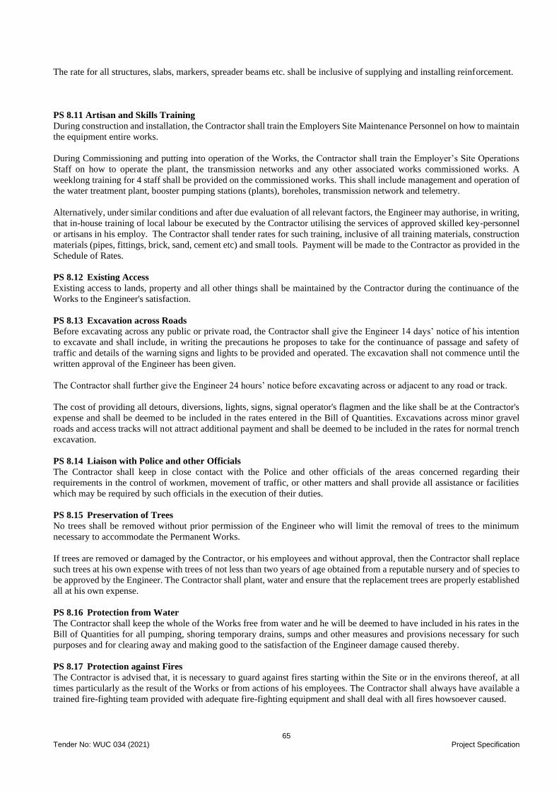
65 Tender No: WUC 034 (2021) Project Specification
The rate for all structures, slabs, markers, spreader beams etc. shall be inclusive of supplying and installing reinforcement.
PS 8.11 Artisan and Skills Training
During construction and installation, the Contractor shall train the Employers Site Maintenance Personnel on how to maintain
the equipment entire works.
During Commissioning and putting into operation of the Works, the Contractor shall train the Employer’s Site Operations
Staff on how to operate the plant, the transmission networks and any other associated works commissioned works. A
weeklong training for 4 staff shall be provided on the commissioned works. This shall include management and operation of
the water treatment plant, booster pumping stations (plants), boreholes, transmission network and telemetry.
Alternatively, under similar conditions and after due evaluation of all relevant factors, the Engineer may authorise, in writing,
that in-house training of local labour be executed by the Contractor utilising the services of approved skilled key-personnel
or artisans in his employ. The Contractor shall tender rates for such training, inclusive of all training materials, construction
materials (pipes, fittings, brick, sand, cement etc) and small tools. Payment will be made to the Contractor as provided in the
Schedule of Rates.
PS 8.12 Existing Access
Existing access to lands, property and all other things shall be maintained by the Contractor during the continuance of the
Works to the Engineer's satisfaction.
PS 8.13 Excavation across Roads
Before excavating across any public or private road, the Contractor shall give the Engineer 14 days’ notice of his intention
to excavate and shall include, in writing the precautions he proposes to take for the continuance of passage and safety of
traffic and details of the warning signs and lights to be provided and operated. The excavation shall not commence until the
written approval of the Engineer has been given.
The Contractor shall further give the Engineer 24 hours’ notice before excavating across or adjacent to any road or track.
The cost of providing all detours, diversions, lights, signs, signal operator's flagmen and the like shall be at the Contractor's
expense and shall be deemed to be included in the rates entered in the Bill of Quantities. Excavations across minor gravel
roads and access tracks will not attract additional payment and shall be deemed to be included in the rates for normal trench
excavation.
PS 8.14 Liaison with Police and other Officials
The Contractor shall keep in close contact with the Police and other officials of the areas concerned regarding their
requirements in the control of workmen, movement of traffic, or other matters and shall provide all assistance or facilities
which may be required by such officials in the execution of their duties.
PS 8.15 Preservation of Trees
No trees shall be removed without prior permission of the Engineer who will limit the removal of trees to the minimum
necessary to accommodate the Permanent Works.
If trees are removed or damaged by the Contractor, or his employees and without approval, then the Contractor shall replace
such trees at his own expense with trees of not less than two years of age obtained from a reputable nursery and of species to
be approved by the Engineer. The Contractor shall plant, water and ensure that the replacement trees are properly established
all at his own expense.
PS 8.16 Protection from Water
The Contractor shall keep the whole of the Works free from water and he will be deemed to have included in his rates in the
Bill of Quantities for all pumping, shoring temporary drains, sumps and other measures and provisions necessary for such
purposes and for clearing away and making good to the satisfaction of the Engineer damage caused thereby.
PS 8.17 Protection against Fires
The Contractor is advised that, it is necessary to guard against fires starting within the Site or in the environs thereof, at all
times particularly as the result of the Works or from actions of his employees. The Contractor shall always have available a
trained fire-fighting team provided with adequate fire-fighting equipment and shall deal with all fires howsoever caused.
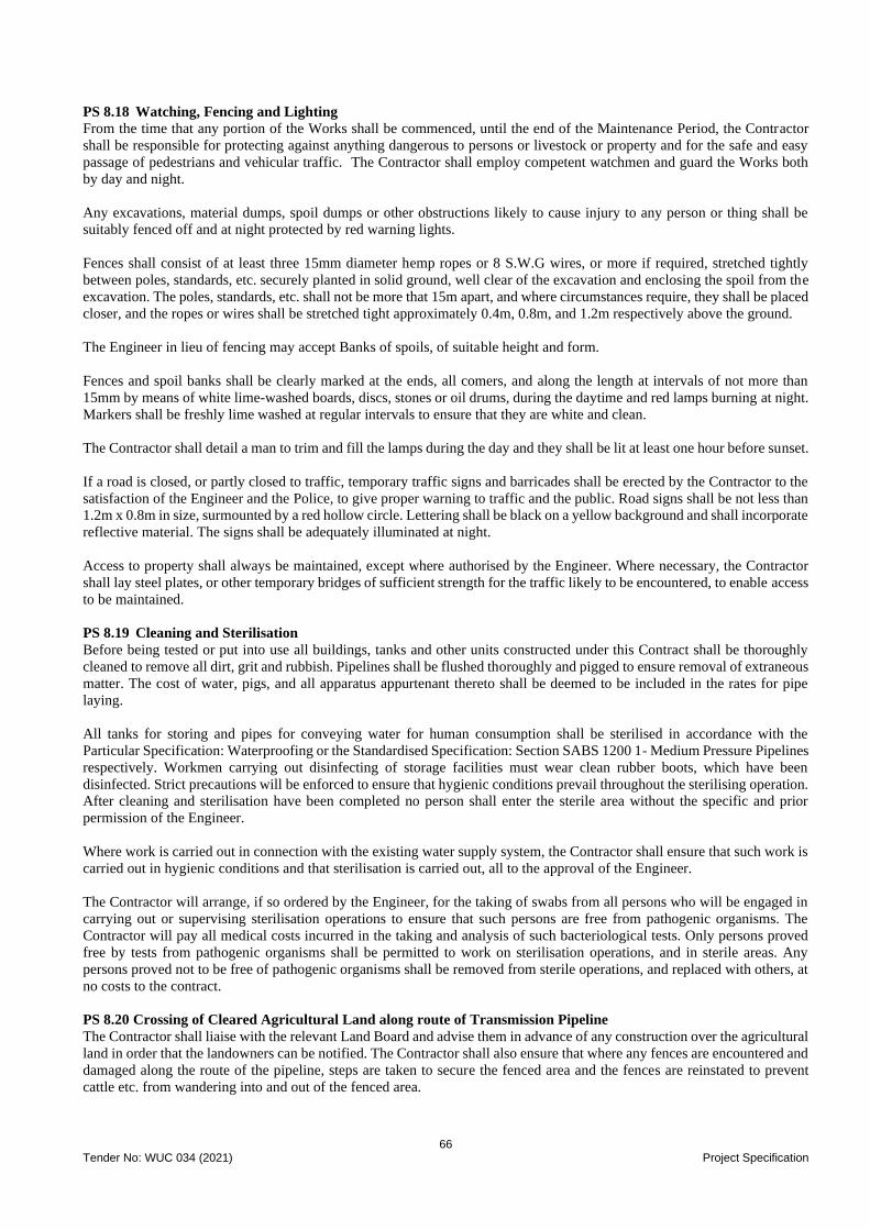
66 Tender No: WUC 034 (2021) Project Specification
PS 8.18 Watching, Fencing and Lighting
From the time that any portion of the Works shall be commenced, until the end of the Maintenance Period, the Contractor
shall be responsible for protecting against anything dangerous to persons or livestock or property and for the safe and easy
passage of pedestrians and vehicular traffic. The Contractor shall employ competent watchmen and guard the Works both
by day and night.
Any excavations, material dumps, spoil dumps or other obstructions likely to cause injury to any person or thing shall be
suitably fenced off and at night protected by red warning lights.
Fences shall consist of at least three 15mm diameter hemp ropes or 8 S.W.G wires, or more if required, stretched tightly
between poles, standards, etc. securely planted in solid ground, well clear of the excavation and enclosing the spoil from the
excavation. The poles, standards, etc. shall not be more that 15m apart, and where circumstances require, they shall be placed
closer, and the ropes or wires shall be stretched tight approximately 0.4m, 0.8m, and 1.2m respectively above the ground.
The Engineer in lieu of fencing may accept Banks of spoils, of suitable height and form.
Fences and spoil banks shall be clearly marked at the ends, all comers, and along the length at intervals of not more than
15mm by means of white lime-washed boards, discs, stones or oil drums, during the daytime and red lamps burning at night.
Markers shall be freshly lime washed at regular intervals to ensure that they are white and clean.
The Contractor shall detail a man to trim and fill the lamps during the day and they shall be lit at least one hour before sunset.
If a road is closed, or partly closed to traffic, temporary traffic signs and barricades shall be erected by the Contractor to the
satisfaction of the Engineer and the Police, to give proper warning to traffic and the public. Road signs shall be not less than
1.2m x 0.8m in size, surmounted by a red hollow circle. Lettering shall be black on a yellow background and shall incorporate
reflective material. The signs shall be adequately illuminated at night.
Access to property shall always be maintained, except where authorised by the Engineer. Where necessary, the Contractor
shall lay steel plates, or other temporary bridges of sufficient strength for the traffic likely to be encountered, to enable access
to be maintained.
PS 8.19 Cleaning and Sterilisation
Before being tested or put into use all buildings, tanks and other units constructed under this Contract shall be thoroughly
cleaned to remove all dirt, grit and rubbish. Pipelines shall be flushed thoroughly and pigged to ensure removal of extraneous
matter. The cost of water, pigs, and all apparatus appurtenant thereto shall be deemed to be included in the rates for pipe
laying.
All tanks for storing and pipes for conveying water for human consumption shall be sterilised in accordance with the
Particular Specification: Waterproofing or the Standardised Specification: Section SABS 1200 1- Medium Pressure Pipelines
respectively. Workmen carrying out disinfecting of storage facilities must wear clean rubber boots, which have been
disinfected. Strict precautions will be enforced to ensure that hygienic conditions prevail throughout the sterilising operation.
After cleaning and sterilisation have been completed no person shall enter the sterile area without the specific and prior
permission of the Engineer.
Where work is carried out in connection with the existing water supply system, the Contractor shall ensure that such work is
carried out in hygienic conditions and that sterilisation is carried out, all to the approval of the Engineer.
The Contractor will arrange, if so ordered by the Engineer, for the taking of swabs from all persons who will be engaged in
carrying out or supervising sterilisation operations to ensure that such persons are free from pathogenic organisms. The
Contractor will pay all medical costs incurred in the taking and analysis of such bacteriological tests. Only persons proved
free by tests from pathogenic organisms shall be permitted to work on sterilisation operations, and in sterile areas. Any
persons proved not to be free of pathogenic organisms shall be removed from sterile operations, and replaced with others, at
no costs to the contract.
PS 8.20 Crossing of Cleared Agricultural Land along route of Transmission Pipeline
The Contractor shall liaise with the relevant Land Board and advise them in advance of any construction over the agricultural
land in order that the landowners can be notified. The Contractor shall also ensure that where any fences are encountered and
damaged along the route of the pipeline, steps are taken to secure the fenced area and the fences are reinstated to prevent
cattle etc. from wandering into and out of the fenced area.
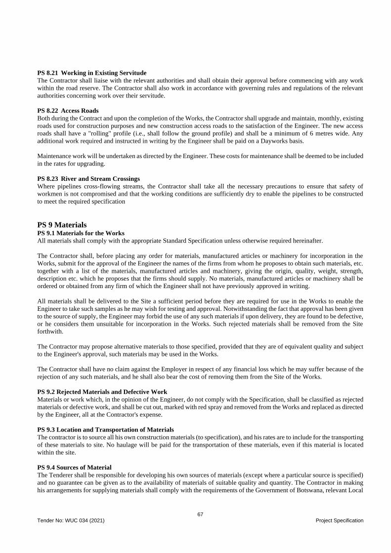
67 Tender No: WUC 034 (2021) Project Specification
PS 8.21 Working in Existing Servitude
The Contractor shall liaise with the relevant authorities and shall obtain their approval before commencing with any work
within the road reserve. The Contractor shall also work in accordance with governing rules and regulations of the relevant
authorities concerning work over their servitude.
PS 8.22 Access Roads
Both during the Contract and upon the completion of the Works, the Contractor shall upgrade and maintain, monthly, existing
roads used for construction purposes and new construction access roads to the satisfaction of the Engineer. The new access
roads shall have a "rolling" profile (i.e., shall follow the ground profile) and shall be a minimum of 6 metres wide. Any
additional work required and instructed in writing by the Engineer shall be paid on a Dayworks basis.
Maintenance work will be undertaken as directed by the Engineer. These costs for maintenance shall be deemed to be included
in the rates for upgrading.
PS 8.23 River and Stream Crossings
Where pipelines cross-flowing streams, the Contractor shall take all the necessary precautions to ensure that safety of
workmen is not compromised and that the working conditions are sufficiently dry to enable the pipelines to be constructed
to meet the required specification
PS 9 Materials PS 9.1 Materials for the Works
All materials shall comply with the appropriate Standard Specification unless otherwise required hereinafter.
The Contractor shall, before placing any order for materials, manufactured articles or machinery for incorporation in the
Works, submit for the approval of the Engineer the names of the firms from whom he proposes to obtain such materials, etc.
together with a list of the materials, manufactured articles and machinery, giving the origin, quality, weight, strength,
description etc. which he proposes that the firms should supply. No materials, manufactured articles or machinery shall be
ordered or obtained from any firm of which the Engineer shall not have previously approved in writing.
All materials shall be delivered to the Site a sufficient period before they are required for use in the Works to enable the
Engineer to take such samples as he may wish for testing and approval. Notwithstanding the fact that approval has been given
to the source of supply, the Engineer may forbid the use of any such materials if upon delivery, they are found to be defective,
or he considers them unsuitable for incorporation in the Works. Such rejected materials shall be removed from the Site
forthwith.
The Contractor may propose alternative materials to those specified, provided that they are of equivalent quality and subject
to the Engineer's approval, such materials may be used in the Works.
The Contractor shall have no claim against the Employer in respect of any financial loss which he may suffer because of the
rejection of any such materials, and he shall also bear the cost of removing them from the Site of the Works.
PS 9.2 Rejected Materials and Defective Work
Materials or work which, in the opinion of the Engineer, do not comply with the Specification, shall be classified as rejected
materials or defective work, and shall be cut out, marked with red spray and removed from the Works and replaced as directed
by the Engineer, all at the Contractor's expense.
PS 9.3 Location and Transportation of Materials
The contractor is to source all his own construction materials (to specification), and his rates are to include for the transporting
of these materials to site. No haulage will be paid for the transportation of these materials, even if this material is located
within the site.
PS 9.4 Sources of Material
The Tenderer shall be responsible for developing his own sources of materials (except where a particular source is specified)
and no guarantee can be given as to the availability of materials of suitable quality and quantity. The Contractor in making
his arrangements for supplying materials shall comply with the requirements of the Government of Botswana, relevant Local

68 Tender No: WUC 034 (2021) Project Specification
Authorities and/or landowners, and will be deemed to have consulted with these parties to acquaint himself with the said
requirements.
There are borrow pits that may be in planned township development areas, which the Land Board / District Council may be
hesitant to expand. Contractors may therefore experience some difficulty in using such borrow pits. It is the Contractor’s
responsibility to test and prove Borrow-Pits and to obtain permission to work them.
It is the Contractor’s responsibility to pay any Royalties or Rentals for the use of Borrow Pits to the appropriate Authority
and to obtain a License from the Department of Mines before commencing any excavation in any Borrow Pit.
PS 9.5 Minerals and Mines Act
The Mines and Minerals Act (Act No. 17 of 1999) applies to this contract and must be complied with.
(i) Definition of “commercial value” of mineral is:
Any mineral on, in or under the natural ground raised for selling or using for any purpose for which directly or
indirectly payment, rental including lease rental and/or any other consideration is intended to be received, shall be
of commercial value.
A mining permit will be required for the abstraction and use of any natural material required for use in the works
e.g., sand, gravel etc.
(ii) Determination of “commercial value”
i) in case of sale it is 3% of the sales value
ii) in case of use of minerals by the person who has raised, it is the market value of that mineral and in the absence
of value in that locality or country only production cost including “overheads” shall be the “sales value” for the
purpose of reckoning royalty.
Minerals obtained by the way of clearing/grubbing, but not intended to be used for “commercial purpose” does not attract
any royalty. Minerals obtained during aligning the road and used for the construction of the same road or for any other
“commercial purpose” shall attract royalty.
For excavation whether on natural or imported material (mineral) shall not attract royalty unless the said material is used for
“commercial purpose”
Royalty at the rate 3% of “sales value” of mineral does not have any zone restriction. Excavation, undercuts, side borrow,
spoil of excess or unsuitable material are not within the preview of royalty, unless material (mineral) obtained by these means
are used for commercial purpose.
The Engineer will not apply for the permit on behalf of the Contractor due to the administrative, contractual and legal
implications thereof. However, the Engineer will assist in this regard if necessary.
Compliance with the Act and the legal obligation therefore must remain with the holder of the permit. Tenderers must
determine the “commercial value” of minerals dependent on its source or production cost including “overheads” for the
purpose of reckoning royalty and provide for payment of this royalty in their unit rates in terms of Act.
Neither the Employer nor the Engineer will be involved in any payment in accordance with the Act.
PS 9.5 Insect and Vermin Proofing
All materials used in the Works shall be resistant to attack by insects, microbiological life or other local fauna.
PS 9.6 Cleaning and Sterilisation
Before being put into use all pipelines constructed under this Contract shall be thoroughly washed out to ensure the removal
of extraneous matter.
PS 10 Existing Services The project involves working within built up areas where water, power and telecommunications utilities have been
constructed. The contractor is responsible for arranging this work with the utilities, for programming the works and for
arranging any temporary road closures or diversion of pipelines etc during the project duration.
PS 10.1 Location and Records of Existing Services

69 Tender No: WUC 034 (2021) Project Specification
It will be the Contractor’s responsibility to locate existing services on site and in the immediate surroundings that will likely
be affected by the works.
Where necessary, proving holes may be dug to locate existing pipelines or components. However, in such instances the
approval of the Engineer shall be obtained prior to the commencement of such work. It must be noted that this work must be
programmed and carried out to the satisfaction of the Engineer before any pipeline excavation is permitted to commence in
any particular area. The Contractor's attention is drawn to the fact that only hand excavation will be permitted in areas where
proving holes are being excavated.
PS 10.2 Protection of Existing Services
Items shall be allowed in the Schedules for the protection of all underground services. The protection of overhead services
such as poles, pylons, overhead conductors, cable stays etc. are the responsibility of the Contractor. Costs for these items are
deemed to have been included in the rate for the excavation of the pipe trenches.
The Contractor shall acquaint himself with the position of all the existing works and services inter alia water mains, sewers,
storm water drains, cables for electricity, telephone lines, telephone, electricity and lighting poles before any excavation is
commenced. Where pipe trenches intersect existing underground services, these services shall be located by hand excavation
prior to the start of any mechanical earthworks operation. It will be the Contractor’s responsibility, through consultation with
the Engineer, to determine these areas.
The Contractor will be held responsible for damage, however caused in the course of the execution of the Works, to existing
works and services. Any damage caused shall be made good at the Contractor's expense. Such existing works and services
where exposed by the executions of the Works shall be properly shored, hung-up and supported to the satisfaction of the
Engineer and of the authority concerned.
The Contractor shall exercise special care when refilling trenches or other excavations around such existing works or services.
Where it is necessary to have existing services including pole stays etc. moved in order to complete any works, it shall be the
Contractor’s responsibility to approach and make arrangements with the relevant Authorities for such work.
If new pipelines need to be relocated due to existing services, buildings, fences, etc. the Contractor must make allowance for
rescheduling working arrangements in his programme to enable the Engineer to approve of the relocation. Poles supporting
cables etc. adjacent to the Works shall be kept securely in place until the Works
are completed and shall then be made as safe and permanent as before.
Notwithstanding the foregoing requirements and without lessening the Contractor's responsibility, the Contractor shall inform
the Engineer immediately of any existing works having been exposed and comply with any requirements of the authority
concerned.
The Contractor shall not interfere in any way with any existing works whether the property of the Employer or of a third
party and whether the position of such works is indicated to the Contractor by the Engineer or not, except where such
interference is specifically described as part of the Works, either in the Contract or in an instruction from the Engineer.
Only when and as directed by the Engineer shall the position of an existing work or service be changed by the Contractor to
meet the requirements of the proposed work and the cost of such work will be paid for on a Daywork basis.
The Contractor shall make adequate provision so that when carrying out his work, no interference, damage or pollution is
caused to highways, footpaths, or to any mains, drains, sewers, etc. or other parts of the Works. Wherever loads have to be
carried over ground in which pipes, valves, culverts, etc. are buried, the Contractor shall take all precautions including where
necessary, the provision and use of sleepered roads, light gauge railways or other means to prevent damage occurring to such
underground works. The fact that the Engineer has approved any means of protection employed shall not relieve the
Contractor of any responsibility in respect of damage occasioned by his operations. The Contractor shall not store any plant
or materials or spoil heaps over existing water mains, or in such positions that interference with access to the mains, control
valves, etc.
When making good the walls of existing structures due to the addition of new structures or the passage of pipes, cables,
drains, etc. the Contractor shall disturb the existing structures as little as possible. All structures shall be made good with a
material similar to that used in the existing works, or such materials considered by the Engineer to be of similar appearance
and suitable in all other respects.
PS10.3 Connecting to Existing Services

70 Tender No: WUC 034 (2021) Project Specification
There are several positions where the Contractor will be required to connect into existing services or isolate. Disruption to
the supply to existing consumers will need to be limited to the absolute minimum necessary to make any connection. It shall
be the Contractor’s responsibility to disconnect and make safe all live services within areas to be isolated after ascertaining
that they do not serve other users. Note that the location of these services is approximate only.
The timing of taking the system out of action to make connections cannot be determined too far in advance. The Contractor
will need, therefore, to make allowance in his programme for this work to suit the requirements of the Service Authority. No
connection shall be undertaken without the full knowledge and agreement of the Service Authority.
Where the Contractor is required to connect an existing service to the new work, the Contractor shall make the following
allowances in his arrangements:
• At least two working days before, inform the Engineer when an existing service is to be exposed.
• Expose the service and confirm the exact dimensions of the pipe to determine the requirements for the connection
fittings and provide a method statement for carrying out the work.
• At least five working days before making the connection arrange with the Engineer and service authority for a
suitable shut down period for the system.
• At least two days before making the connection lay out the fittings for the connection for inspection by the
Engineer.
• After shutdown, break into the existing pipeline and install the connection fittings. Once work has commenced,
this must continue until the connection is complete and service can be resumed.
• Provide all information for the work carried out and for the existing pipe, record; pipe material, pipe size
(diameter), pipe class, etc. for submission to the Engineer for database update.
• Provide temporary anchors and supports, where necessary, until remaining pipework is complete.
PS10.4 Overhead Power Lines
Where work is being carried out in the vicinity of overhead power lines, the Contractor is responsible for ensuring that all
persons working in such areas are aware of the relatively large distance that high voltage electricity can "short" to earth when
cranes or other large masses of steel are in the vicinity of power lines. The Contractor's attention is drawn to BS 162, which
gives safe clearance for various voltages.
The Contractor shall take all necessary precautions to ensure the safety of his employees and all other persons where work is
being carried out in the vicinity of overhead power lines.
PS11 Specifications and Applicable Standards
PS11.1 Standard Specifications
The specification in general use will be SANS 1200 as published by the South African National Standards.
For convenience, and to establish the necessary standards of quality, reference has been made to Specifications issued by
national or other widely recognised bodies. Such specifications shall be referred to as "Applicable Standards" and apply to
versions issued prior to the issue of the Tender Documents, together with such additions and amendments as may have been
issued prior to the same date.
Subject to the written approval of the Engineer any other internationally accepted Applicable Standard which requires an
equal quality of work might be used.
In referring to Applicable Standards, the following abbreviations are used.
BS British Standard
SANS South African National Standards
ISO International Organisation of Standardisation
PS11.2 Units
In this Specification, the Drawings, and the Schedule of Quantities, the metric system of dimensioning has been adopted
except where it is understood that suppliers and manufacturers are not yet able to provide materials in metric sizes.
Where dimensions are given in metric units for materials, which are only available in Imperial dimensions, and vice versa,
the Contractor may, subject to his obtaining the prior approval of the Engineer, substitute the nearest equivalent available
standard size in the other system.

71 Tender No: WUC 034 (2021) Project Specification
PS11.3 Standardised Specifications
For the purposes of this contract, the following Standardised Specifications, in accordance with SANS 1200, and Particular
Specifications shall apply:
Standardised Specifications
SANS 1200 A - 1986: General
SANS 1200 AB - 1986: Engineer's Office
SANS 1200 C - 1982: Site Clearance
SANS 1200 D - 1988: Earthworks
SANS 1200 DB - 1989: Earthworks (Pipe Trenches)
SANS 1200 DK - 1996: Gabions and Pitching
SANS 1200 DM - 1981: Earthworks (Roads, Sub-grade)
SANS 1200 G - 1982: Concrete (Structural)
SANS 1200 GA - 1982: Concrete (Small Works)
SANS 1200 L - 1983: Medium Pressure Pipelines
SANS 1200 LB - 1983: Bedding (Pipes)
Particular Specifications
PAF Applied Finishes
PB Blasting
PK Brickwork and Masonry
PSW Water Test
PV Valves
The following Standards and Codes of Practice are referred to in the Specification for Electrical and Mechanical components
and are applicable to these works:
American National Standards Institute
ANSI B4.1 Preferred limits and fits for cylindrical parts
American Society of Mechanical Engineers
ASME Section VIII Boiler and Pressure Vessel Code, Division 1 for Unfired Pressure Vessels
British Standards Institution
BS 916 Black bolts, screws and nuts
BS 970 Wrought steels in the form of blooms, billets, bars and forgings
BS 1452 Specification for grey iron castings
BS 2789 Specification for spheroidal graphite or nodular graphite cast iron
BS 3100 Specification for steel castings for general engineering purposes
BS 3468 Austenitic cast iron
BS 4080 Methods for non-destructive testing of steel castings
BS 4504 Flanges and bolting for pipes, valves and fittings
BS 5316 Specification for acceptance tests for centrifugal, mixed flow and axial pumps
South African Bureau of Standards
SANS 1109 ISO pipe threads for pipes and fittings where pressure-tight joints are made
SANS 0140 Identification colour marking (Part II)
International Standards Organisation
ISO 9001 Quality assurance
ISO 9002 Quality systems. Model for quality assurance in production, installation and service

72 Tender No: WUC 034 (2021) Project Specification
SCHEDULE 1.1: Book of Drawings - List of Tender Drawings and Attachments
A set of Contract 4 Drawings has been provided under a separate cover. The drawings are provided for guidance only.

73 Tender No: WUC 034 (2021) Project Specifications
SCHEDULE 1.2 - Engineers Site Office Furniture and Equipment
The Contractor shall provide, install, connect and commission the following furniture and equipment for the Engineer's office.
One office facility shall be provided and furnished for the Engineer’s Representative and maintained for the duration of the
contract. The office facility shall be furnished as per SANS 1200 AB, save as amended below:
The office shall have a floor area of at least 350 m² and a ceiling height of at least 2.5m. All offices and other facilities shall
be weatherproof and shall be provided with ceilings, with a door with a secure lock, and each office shall have two opening
windows of glazed area of atleast 3m². Each facility shall be well ventilated and shall be so insulated as to provide
comfortable working conditions. An outside sitting area under a shaded port with chairs and a table to sit 10 people shall be
provided
Furniture and Office Equipment
• 1 fixed PABX telephone line onsite with extensions to 6No offices
• Internet connection on site capable of 20mbps internet speeds
• Server with network points to all offices and reception area, and to the printer and large paper plotter
• 1 No. multi-function Photocopier-Printer-Scanner complete with sorting trays etc., Altalink C8055 or similar.
• 1 No multi-function large paper plotter (A0, A1, A2 etc) including scanning
• 1 No 70inch smart-tv complete with wall mounting accessories (for placement in conference room)
• 5 No. site camera, 20 mega pixels or higher
• 20Nos. Scientific calculators with basic trigonometrical functions
• 1 No. Full set of the latest copy of SANS 1200 - Standard Specification as published by the South African Bureau
of Standards.
• 1 No. Full set of the SANS 0120 – Code of Practice Published by South African Bureau of Standards
• 2 No. Conditions of Contract for Construction – Second Edition 2017 published by FIDIC
• 2 No. The FIDIC Contracts Guide – First edition 2000 published by FIDIC
• 1 No. TMH 1 - Standard Test Methods books (latest version)
• 16 No. Mica Wallboards (Minimum 2m x 2m)
• 1No L-shaped writing desk with 6 lock up drawers (1.8m by 0.8m double pedestal)
• 4No. Writing desks with 6 lock up drawers (1.8m by 0.8m double pedestal)
• 13 No. Writing desks with 3 lock up drawers (1.2m by 0.8m single pedestal)
• 1 No. Conference table capable of seating thirty (30) people (Domino or similar approved). Table shall have desk
minimum 4No cable pop up with power outlets points, HDMI, round sockets & two pin sockets.
• 30 No. chairs (Pisa or similar approved) for the conference table
• 19 No. Office swivel chairs
• 18 No Office visitor chairs (non-swivel)
• 1 No. Receptionist swivel chair
• 1 No. Receptionist table (L or C shaped type)
• 4No office visitor chairs and table
• 4 No. 2.5m by 1m Angled Plan Tables
• 14 No. 2m Long by 4 deep bookshelves capable of accommodating A4 Box Files.
• 3 No. Steel lockers with 24 lockable compartments
• 4 No. Lockable steel cupboards with 4 shelves
• 4 No. Drawing hanging racks with adequate clips for hanging drawings
• 20 No 3 level desk tray organisers
• 12 No. Stapling machines
• 2 No. Heavy duty stapling machines
• 12 No. Paper punches
• 2 No. Heavy duty punches
• Air conditioning units incorporating heating and cooling for each room. Air-condition shall be sized
appropriately considering the size of the room
• 2 No. First aid kits
• 3 No. 4.5 kg Fire extinguishers (or to suit the office building as determined by local authority)
• 13 No. Wastepaper baskets
• 1 No. Large Dustbin
• 1 No. Tea Urn
• 1 No. Water Cooler
• 1 No. Kettle

74 Tender No: WUC 034 (2021) Project Specifications
• 1 No. 360L sized fridge/freezer
• 1 No bar fridge
• 1 No. Microwave oven (900 W capacity)
• 1 No. table and 4No chairs for the kitchen
• Kitchenware & crockery

75 Tender No: WUC 034 (2021) Project Specification
Computer Equipment - Desktop
15 No. desktop with the following specification
Dell or HP Workstation with the following specifications: 10th Generation Intel Core i5 - 9600K Processor,
minimum 16 GB RAM - DDR4 2666MHz RAM, 1TB (7200rpm) SATA HDD, DVD/CD-RW Combo, Intel
10/100/1000 Network Card, 20" Dell / HP Monitor, Integrated Intel UHD Graphics 360 or NVIDIA GTX 1650
Graphics Card, Windows 10 Pro x64bit, USB 3.0 Keyboard and OPTICAL Mouse, Transparent soft
plastic/rubber keyboard cover, complete with computer stands and dust covers.
Together with
• 15 No. Storage Disks of 1TB capacity
• 1 No. HP Officejet Printer, 28 ppm in colour, 4800*1200dpi resolution, with USB Connection
• 15 No. Uninterrupted Power Supplies (UPS) for computers, printers and plotter.
• 1 No. Line Voltage regulators with surge protection of 3000W capacity for computers, printers and plotter
Software (Latest Versions) and Internet
• 15 No. Windows live
• 15 No. Microsoft Windows 10 Professional
• 15 No. Microsoft Office 365 standard
• 15 No. Kaspersky Total or Internet Security – latest version
• 3 No. Civil Designer latest version for Windows
• 15 No. AutoCad Standard 2020 version
• 15 No. Internet connection to local Internet Service Provider (Fibre to the Office, Office Wired and Wireless
LAN connecting all client machines and or resources).
Computer Equipment - Laptop
6 No. laptops with the following specification
Dell XPS 15 Mobile Workstation Laptop or similar approved with the following specifications: 9th Generation Intel
Core i9 - 9980K Processor, 1TB M.2, Gen 3 PCIe x4 NVMe SSD, 15.6" 4K UHD (3840 x 2160) Display, 32GB
DDR4 2666MHz RAM, NVIDIA GeForce GTX 1650 Graphics Card, Wireless LAN, etc complete with Windows
10 Pro 64bit.
Together with
• 6 No. Storage Disks of 2TB capacity
• Wireless mouse
• Carryon laptop bag
Software (Latest Versions) and Internet
• 6 No. Windows live
• 6 No. Microsoft Windows 10 Professional
• 6 No. Microsoft Office Professional - 2019
• 2 No. Microsoft Project Professional
• 4 No Microsoft Project Standard
• 6 No. Kaspersky Total or Internet Security – latest version
• 3 No. Civil Designer latest version for Windows
• 6 No. AutoCad Standard 2020 version with 3 licences for Windows
• 6 No. Internet connection to local Internet Service Provider (Fibre to the Office, Office Wired and Wireless LAN
connecting all client machines and or resources).
Software updates, dongles to be supplied by the Contractor for the duration of the Project.
Recommended Brand Names for Computer Equipment are Hewlett Packard, Dell, Lenovo, Acer, and Mercer
General Obligations
All furniture and office equipment shall be new.

76 Tender No: WUC 034 (2021) Project Specifications
The Contractor shall keep the offices in a satisfactory clean and fully habitable condition and shall maintain and repair all
services, furniture and equipment. The Contractor shall have a maintenance contract shall be placed for the computers, server,
and printer as well as for the Photocopier and Fax machines and shall attend to all queries from the Engineer and Employer
on any of the computers and printers as well as challenges with the server. His response to such issues shall be within one
day to avoid impacting on the work of the Engineer. The Contractor shall provide for collection of refuse and shall pay all
charges and rental for the provision of electricity and telephones. The Contractor will be reimbursed the Cost of all telephone
calls. All cell phone calls will be reimbursed through the Contract.
The Contractor shall insure the office and the residences provided to the Engineer’s resident staff including the contents,
irrespective of whether or not provided by the Contractor, against loss or damage by accident, fire and theft for the duration
of the Contract.
The Contractor shall erect and hand over to the Engineer the offices, fully furnished and equipped within the specified period.
The Employer may deduct from any monies due, expenditure incurred by the Employer because of the Contractor failing to
complete the above building by the due date.
All the above office furniture and equipment shall revert to the Employer at the end of the Defects Notification Period or
earlier at the discretion of the Employer. The computer equipment shall be handed over to the Employer or to any other
person nominated by the Employer, at the end of the Defects Notification Period or earlier at the discretion of the Employer.
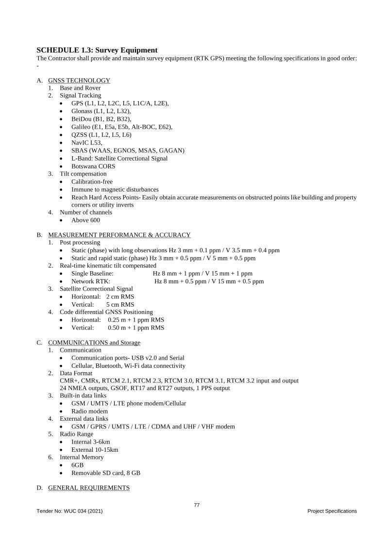
77 Tender No: WUC 034 (2021) Project Specifications
SCHEDULE 1.3: Survey Equipment The Contractor shall provide and maintain survey equipment (RTK GPS) meeting the following specifications in good order:
-
A. GNSS TECHNOLOGY
1. Base and Rover
2. Signal Tracking
• GPS (L1, L2, L2C, L5, L1C/A, L2E),
• Glonass (L1, L2, L32),
• BeiDou (B1, B2, B32),
• Galileo (E1, E5a, E5b, Alt-BOC, E62),
• QZSS (L1, L2, L5, L6)
• NavIC L53,
• SBAS (WAAS, EGNOS, MSAS, GAGAN)
• L-Band: Satellite Correctional Signal
• Botswana CORS
3. Tilt compensation
• Calibration-free
• Immune to magnetic disturbances
• Reach Hard Access Points- Easily obtain accurate measurements on obstructed points like building and property
corners or utility inverts
4. Number of channels
• Above 600
B. MEASUREMENT PERFORMANCE & ACCURACY
1. Post processing
• Static (phase) with long observations Hz 3 mm + 0.1 ppm / V 3.5 mm + 0.4 ppm
• Static and rapid static (phase) Hz 3 mm + 0.5 ppm / V 5 mm + 0.5 ppm
2. Real-time kinematic tilt compensated
• Single Baseline: Hz 8 mm + 1 ppm / V 15 mm + 1 ppm
• Network RTK: Hz 8 mm + 0.5 ppm / V 15 mm + 0.5 ppm
3. Satellite Correctional Signal
• Horizontal: 2 cm RMS
• Vertical: 5 cm RMS
4. Code differential GNSS Positioning
• Horizontal: 0.25 m + 1 ppm RMS
• Vertical: 0.50 m + 1 ppm RMS
C. COMMUNICATIONS and Storage
1. Communication
• Communication ports- USB v2.0 and Serial
• Cellular, Bluetooth, Wi-Fi data connectivity
2. Data Format
CMR+, CMRx, RTCM 2.1, RTCM 2.3, RTCM 3.0, RTCM 3.1, RTCM 3.2 input and output
24 NMEA outputs, GSOF, RT17 and RT27 outputs, 1 PPS output
3. Built-in data links
• GSM / UMTS / LTE phone modem/Cellular
• Radio modem
4. External data links
• GSM / GPRS / UMTS / LTE / CDMA and UHF / VHF modem
5. Radio Range
• Internal 3-6km
• External 10-15km
6. Internal Memory
• 6GB
• Removable SD card, 8 GB
D. GENERAL REQUIREMENTS

78 Tender No: WUC 034 (2021) Project Specifications
1. Power management
• Internal Power Supply
• External Power Supply
• Operation time: at least 6hrs with all functions
2. Field & Office Software
• Office software- server based concurrent licence minimum 5 users
3. Local Support
• Authorisation Certificate
4. Hardware & Software Maintenance Plan
• Provide plan
5. Warranty
• 2 years
E. RAGGED CONTROLLER
1. Operating system
Windows 10 Enterprise
2. System
• Processor Intel® 6th Generation Core i7
• Memory (RAM) 8 GB Ram Internal storage 256 GB SSD
• Screen size 10.1“capacitive multi-touch
• Battery life 11 hours
3. Connectivity & Communication
• USB host 1 x USB 3.0 & 1 x USB 2.0
• Power jack
• Audio jack
• Bluetooth
• WLAN
• Cellular modem 4G LTE (data only) GSM / UMTS / LTE
• Wi-Fi
4. User Interface
• Touch screen
• On screen keyboard
• Camera Rear: 5MP
5. GNSS
• Internal antenna: 72 channels: GPS L1C/A, GLONASS, Beidou, QZSS, SBAS
• Real-time: SBAS
• Dual constellation system: GPS/GLONASS
6. Software
• Loaded with all necessary software’s
7. Accessories
• Carry Bag
• Battery Pack
• Hand strap
• AC-DC power adaptor with power cord
• Digital Pen and mounting clip
• Earphones
• Screen protector
• Vehicle power supply
• Keyboard with trackpad
• Office Dock
• Pole Mount
• Vehicle Mount with keypad
8. Warranty
• 2 years

79 Tender No: WUC 034 (2021) Project Specifications
OTHER SURVEY ACCESSORIES
2No Handheld GPS equipment complete with accessories and software, including maintenance kit, data transfer
cable, PC kit, rechargeable batteries etc.
4 No. Aluminium staff (5 section) or equivalent
2 No. 100m steel tape
2 No. 30m fibreglass tape
6No. 2m ranging rods
4 No. Change Plates for aluminium staff
2 No. Measuring Wheel "Trumeter" or Similar approved.
6 No. 5 m retractable tapes
4 No. 4-pound hammer.
4 No. Trowel.
4 No. Shovels
2 No. Water containers (20l)
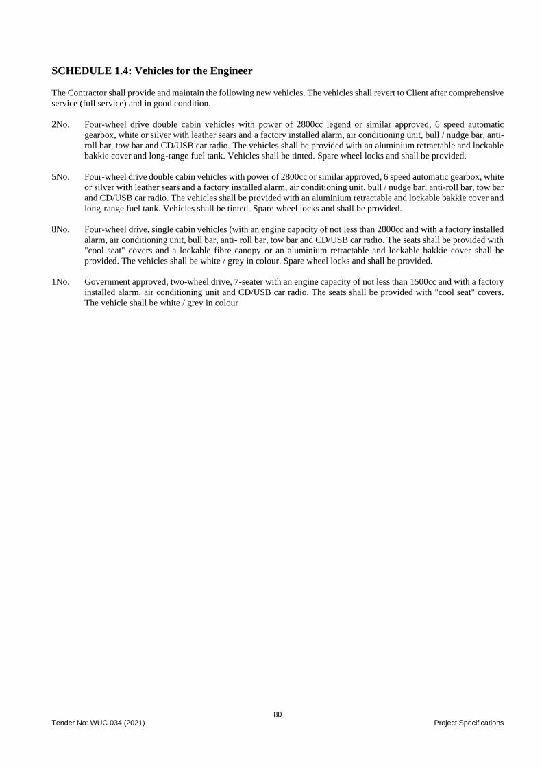
80 Tender No: WUC 034 (2021) Project Specifications
SCHEDULE 1.4: Vehicles for the Engineer
The Contractor shall provide and maintain the following new vehicles. The vehicles shall revert to Client after comprehensive
service (full service) and in good condition.
2No. Four-wheel drive double cabin vehicles with power of 2800cc legend or similar approved, 6 speed automatic
gearbox, white or silver with leather sears and a factory installed alarm, air conditioning unit, bull / nudge bar, anti-
roll bar, tow bar and CD/USB car radio. The vehicles shall be provided with an aluminium retractable and lockable
bakkie cover and long-range fuel tank. Vehicles shall be tinted. Spare wheel locks and shall be provided.
5No. Four-wheel drive double cabin vehicles with power of 2800cc or similar approved, 6 speed automatic gearbox, white
or silver with leather sears and a factory installed alarm, air conditioning unit, bull / nudge bar, anti-roll bar, tow bar
and CD/USB car radio. The vehicles shall be provided with an aluminium retractable and lockable bakkie cover and
long-range fuel tank. Vehicles shall be tinted. Spare wheel locks and shall be provided.
8No. Four-wheel drive, single cabin vehicles (with an engine capacity of not less than 2800cc and with a factory installed
alarm, air conditioning unit, bull bar, anti- roll bar, tow bar and CD/USB car radio. The seats shall be provided with
"cool seat" covers and a lockable fibre canopy or an aluminium retractable and lockable bakkie cover shall be
provided. The vehicles shall be white / grey in colour. Spare wheel locks and shall be provided.
1No. Government approved, two-wheel drive, 7-seater with an engine capacity of not less than 1500cc and with a factory
installed alarm, air conditioning unit and CD/USB car radio. The seats shall be provided with "cool seat" covers.
The vehicle shall be white / grey in colour

81 Tender No: WUC 034 (2021) Project Specifications
SCHEDULE 1.5 – Furniture and Equipment for Engineer’s Staff Houses Full list of furniture and equipment for each of the staff houses shall be as follows: -
ITEM TYPE I (3 Bed) TYPE II (2 bed)
3 Piece Lounge Suite (Sofas) 1 0
2 Piece Lounge Suite 0 1
Coffee Table 1 1
TV Stand 1 1
LED Television set (46 inch) 1 1
Dining Table 1 0
Dining Chairs 6 0
3 Drawer Desk with Chair (home computer desk) 1 0
Bookcase 1 1
Double Sealy Bed complete with headboard 2 1
Single Sealy Bed 1 1
Bedside Cabinets 2 2
Dressing Table with Chair 1 1
Chest of Drawers 2 1
Bed Linen (sets per bedroom) 2 Sets 2 Sets
Bedside lamps 2 2
Curtain 1 Set 1 Set
Bathroom Cabinet 1 1
4 Plate Electric Stove with Grill and Warmer 1 1
Fridge - Freezer (300lites) 1 1
Microwave oven 1 1
Automatic, Cordless kettle (1.7litres) 1 1
Cooking Utensils, Cutlery and Crockery 1 Set 1 Set
Air Conditioning Unit 3 2
Electric Overhead Fans 1 1
Dustbin 1 1
Rotary Clothesline 1 1
Type 1 House = 3 Bedroomed
Type 2 House = 2 Bedroomed
The type and quality of furnishings in the above schedule shall be to an acceptable standard and shall be subject to
the approval of the Engineer.

82 Tender No: WUC 034 (2021) Project Specifications
SCHEDULE 1.6 Weather recording equipment and manuals for the Contract
The Contractor shall provide throughout the period of construction the following weather recording equipment, which on
completion of the Works shall remain the property of the Contractor. The laboratory equipment so provided shall be new.
All such equipment shall comply with BS, AASHTO, SABS or equal approved.
Any additional or specialist laboratory equipment over and above those listed herein that may be required in writing by the
Engineer shall be provided by the Contractor.
Thermometer - 10 to 110°C 2 No.
Concrete Thermometer 2 No.
Max/min thermometer-20DC to 50DC 2 No.
Rain Gauge 2 No.
Adjustable Spanner 2 No.
AASHTO Testing (book) 2 No.
AASHTO Specifications (book) 2 No.
The equipment will revert to the property of the Contractor at the end of the contract.
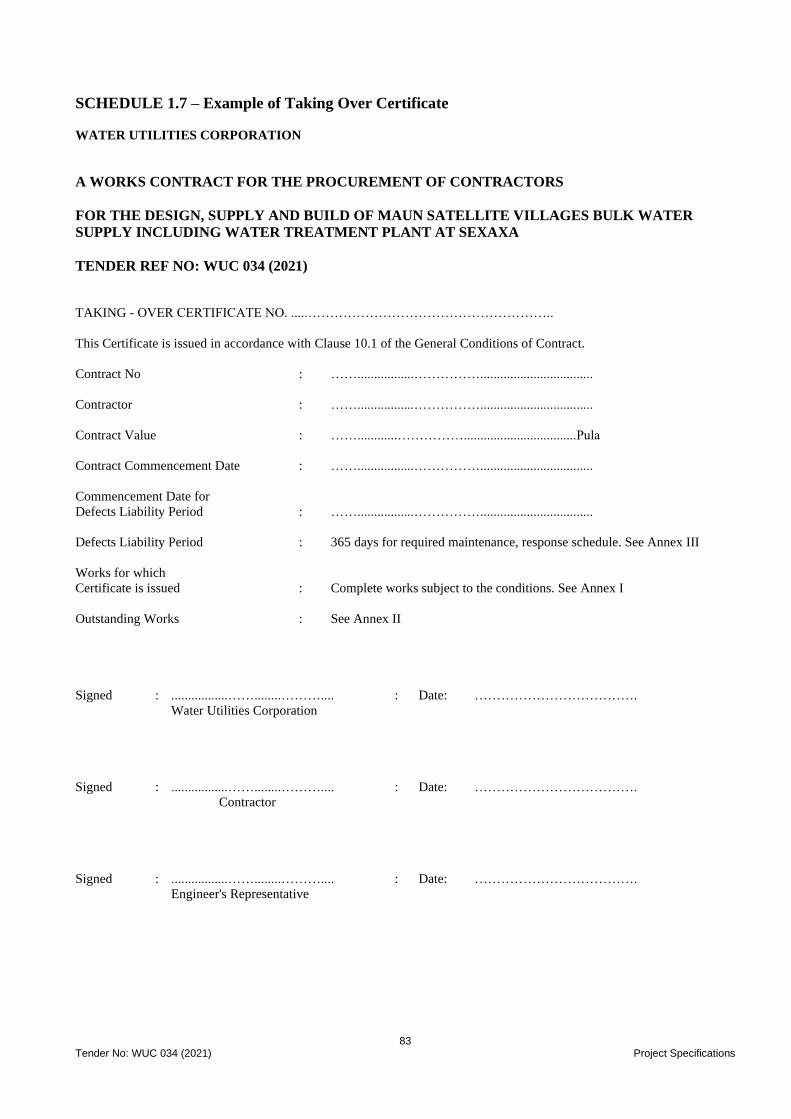
83 Tender No: WUC 034 (2021) Project Specifications
SCHEDULE 1.7 – Example of Taking Over Certificate
WATER UTILITIES CORPORATION
A WORKS CONTRACT FOR THE PROCUREMENT OF CONTRACTORS
FOR THE DESIGN, SUPPLY AND BUILD OF MAUN SATELLITE VILLAGES BULK WATER
SUPPLY INCLUDING WATER TREATMENT PLANT AT SEXAXA TENDER REF NO: WUC 034 (2021)
TAKING - OVER CERTIFICATE NO. .....………………………………………………..
This Certificate is issued in accordance with Clause 10.1 of the General Conditions of Contract.
Contract No : …….................……………..................................
Contractor : …….................……………..................................
Contract Value : ……............……………..................................Pula
Contract Commencement Date : …….................……………..................................
Commencement Date for
Defects Liability Period : …….................……………..................................
Defects Liability Period : 365 days for required maintenance, response schedule. See Annex III
Works for which
Certificate is issued : Complete works subject to the conditions. See Annex I
Outstanding Works : See Annex II
Signed : .................……........……….... : Date: ……………………………….
Water Utilities Corporation
Signed : .................……........……….... : Date: ……………………………….
Contractor
Signed : .................……........……….... : Date: ……………………………….
Engineer's Representative

84 Tender No: WUC 034 (2021) Project Specifications
ANNEX I
WATER UTILITIES CORPORATION
A WORKS CONTRACT FOR THE PROCUREMENT OF CONTRACTORS
FOR THE DESIGN, SUPPLY AND BUILD OF MAUN SATELLITE VILLAGES BULK WATER
SUPPLY INCLUDING WATER TREATMENT PLANT AT SEXAXA TENDER REF NO: WUC 034 (2021)
TAKING-OVER CERTIFICATE
CONDITIONS FOR GRANTING SUBSTANTIAL COMPLETION
The contractor must agree to the following:
1. The outstanding work will be satisfactorily complete in the time schedule provided (See Annex II).
2. Site facilities shall be provided until the outstanding work (Annex II) is completed. The project will be satisfactorily
maintained with maintenance work being carried out within the time specified in the maintenance response schedule
(See Annex III).
3. Payment for the outstanding work will not be approved until it is to the satisfaction of the Engineer. Half of the retention
money will be released.
Agreed : .................……........……….... : Date: ……………………………….
Contractor
Witnessed : .................……........……….... : Date: ……………………………….
Engineer
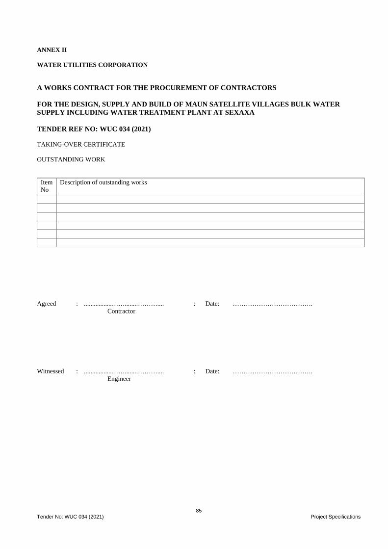
85 Tender No: WUC 034 (2021) Project Specifications
ANNEX II
WATER UTILITIES CORPORATION
A WORKS CONTRACT FOR THE PROCUREMENT OF CONTRACTORS
FOR THE DESIGN, SUPPLY AND BUILD OF MAUN SATELLITE VILLAGES BULK WATER
SUPPLY INCLUDING WATER TREATMENT PLANT AT SEXAXA TENDER REF NO: WUC 034 (2021)
TAKING-OVER CERTIFICATE
OUTSTANDING WORK
Item
No
Description of outstanding works
Agreed : .................……........……….... : Date: ……………………………….
Contractor
Witnessed : .................……........……….... : Date: ……………………………….
Engineer
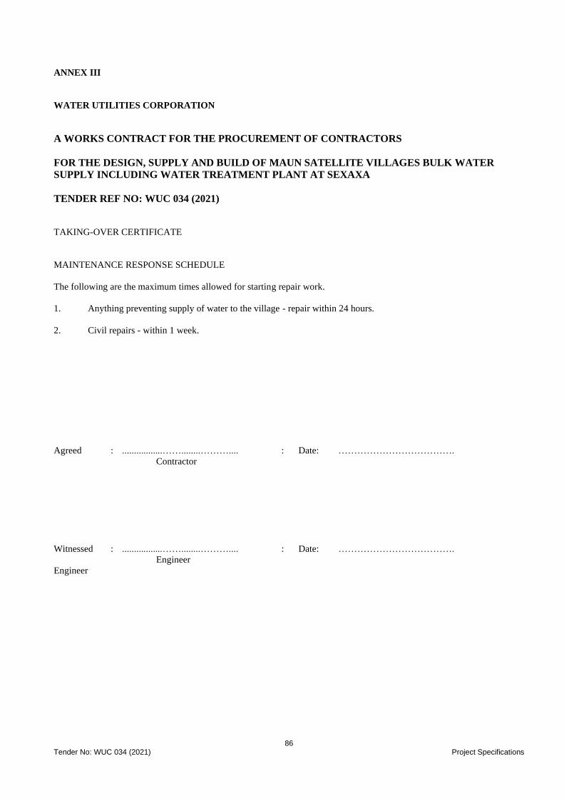
86 Tender No: WUC 034 (2021) Project Specifications
ANNEX III
WATER UTILITIES CORPORATION
A WORKS CONTRACT FOR THE PROCUREMENT OF CONTRACTORS
FOR THE DESIGN, SUPPLY AND BUILD OF MAUN SATELLITE VILLAGES BULK WATER
SUPPLY INCLUDING WATER TREATMENT PLANT AT SEXAXA TENDER REF NO: WUC 034 (2021)
TAKING-OVER CERTIFICATE
MAINTENANCE RESPONSE SCHEDULE
The following are the maximum times allowed for starting repair work.
1. Anything preventing supply of water to the village - repair within 24 hours.
2. Civil repairs - within 1 week.
Agreed : .................……........……….... : Date: ……………………………….
Contractor
Witnessed : .................……........……….... : Date: ……………………………….
Engineer
Engineer
87 Tender No: WUC 034 (2021) Amendment to Standard Specification
WATER UTILITIES CORPORATION
CONTRACT PART 3
SCOPE OF WORK
PROJECT SPECIFICATIONS
AMENDMENTS TO
STANDARDISED SPECIFICATIONS
A WORKS CONTRACT FOR THE PROCUREMENT OF CONTRACTORS
FOR THE DESIGN, SUPPLY AND BUILD OF MAUN SATELLITE VILLAGES BULK WATER
SUPPLY INCLUDING WATER TREATMENT PLANT AT SEXAXA
TENDER REF NO: WUC 034 (2021)
Project Specifications - Portion 2: Amendments to Standardised Specifications
General (SANS 1200 A)
2.1A 1 Contract Price Adjustment to Preliminary and General Amounts
Delete the Sub-Clause 8.2.3 in its entirety.
2.2B Engineer’s Office (SANS 1200 AB)
Refer to Clauses and Schedule 1.2 of the Project Specification these will take precedence over the Clauses as stated in the
SANS 1200AB1 to 11.
2.2AB12 Definitions
Delete this clause in its entirety.
2.3C Site Clearance (SANS 1200 C)
2.3C 1 Clearance of Ground
The contractor shall clear all ground within a 3m wide strip for all vegetation and all visible obstructions along the routes of
pipelines, unless ordered otherwise by the Engineer. No trees may be removed in any of the areas to be cleared and grubbed
without the approval of the Engineer.
All vegetation from the site clearing together with branches and stumps from cut trees, where the cutting down of trees is
authorised, must be removed to an approved designated dumping site. All costs for loading, transporting and dumping must
be allowed for in the relevant Site Clearance payment items.
After clearing and grubbing, the Contractor is to request for the area to be inspected by the Engineer. Payment shall only be
made where approved by the Engineer.
Preservation of Trees and Shrubs (Sub-Clause 5.2.3)
The penalty in respect of every individual tree and shrub designated as a tree or shrub to be preserved that is damaged or
removed unnecessarily by the Contractor, shall be P 1,000. Trees that fall within areas upon which the Works are to be
constructed or within areas that the Contractor must occupy for the proper construction of the Works will not be designated
for preservation
2.3C 2 Removal of Topsoil
Topsoil removal will only be paid for where specifically ordered by the Engineer. Topsoil stripping will only be ordered in
road fill areas and road cut areas where earth is to be used for cut to fill purposes. The rate for topsoil removal shall be
inclusive of spoiling of topsoil to an approved dumping site. No additional payment shall be made for double handling of
topsoil.
Where topsoil is to be spoilt, such shall be done after approval by the Engineer. The rate for topsoil removal shall be inclusive
of spoiling of topsoil to an approved dumping site. No additional payment shall be made for double handling of topsoil.
88 Tender No: WUC 034 (2021) Amendment to Standard Specifications
2.4DB Earthworks (Pipe Trenches) (SANS 1200 DB)
2.4DB 1 Backfill Materials
Backfill materials shall contain no organic material.
2.4DB 2 Existing Services
Refer to the Clauses PS 11 in Portion 1 of the Project Specification.
2.4DB 3 Base Widths
Base widths shall be determined from the nominal pipe diameter as shown on the drawings and the side allowance on each
side as stated in Sub-Clause 5.2 in SANS 1200 DB.
2.4DB 4 Blasting of Hard Rock
The contractor shall always keep in his office at the site copies of Botswana Laws applying to transportation, storage and use
of explosives and shall supply one copy of the laws to the Engineer. The Contractor shall also submit to the Engineer a copy
of any instructions or notices which the contractor may issue to his staff or workmen or post about the site in compliance
with such country laws.
Any blasting procedures for the excavation of hard rock must take account of the proximity of existing dwellings and the
applicable safety regulations must be rigorously implemented to safeguard residents and their livestock and to minimise the
risk of any damage to the existing structures and underlying pipework. Refer to Particular Specification - PB Blasting. or BS
5607
2.4DB 5 Disposal of Material
Surplus excavated material from pipe trenches or material which is unsuitable for backfilling must be spoiled off site at an
approved designated dumping site selected by the Contractor. All costs for loading, transporting and dumping must be
allowed for in the relevant payment items. No overhaul will be paid for transporting spoil material to this site.
2.4DB 6 Shoring
Allowance must be made in excavation rates for shoring deep trenches in accordance with Subclause 5.1.1 to meet the local
safety standards.
Where excavating opposite structures, existing services or in restricted areas when instructed by the Engineer, the Contractor
shall shore the trench in a method approved by the Engineer. Payment for this shoring will only be made where specifically
ordered by the Engineer. Work will be paid for as originally conceived and the Contractor will be held liable if a changed
method of his choice causes damage to surrounding properties, services, fences, etc.
2.4DB 7 Double Handling of Excavated Material
Where reserve widths do not permit the stockpiling of excavated trench material alongside the trench due to the volume of
material, the need for access or for any other reason, the Engineer may order in writing double handling of excavated material,
stockpiling elsewhere on site and replacing after pipe laying has been completed. Payment for double handling will be
calculated on the m3 (Cubic metre) measure of the in-situ material prior to excavation and will include for stockpiling, haulage
and replacing after pipe laying has been completed.
2.4DB 8 Material to Provide Additional Cover to Pipes
In certain areas where additional cover is required to pipelines as a result of shallow pipelines and possible flotation conditions
under high water table conditions, surplus excavation material shall be used. In the absence of surplus excavation material
being available, imported material shall be used. These operations shall be carried out only on the written instruction of the
Engineer.
2.4DB 9 Excavation of New Services Close to One Another
Situations may arise where new services run parallel and close to one another, but at different grades and depths. Measurement
and payment for excavation shall be deemed to be for each service separately. No additional payment for the protection of
the new service which is laid first shall be paid.
2.4DB 10 Excavation Across Surfaced Main Road
The Contractor shall, before excavations commence, give the Engineer and the Road Authority concerned 10 days’ notice of
his intention to excavate. The Contractor shall include, in writing, the precautions he proposes to take for the continuance of
passage and safety of traffic and details of the warning signs and lights to be provided and operated.
89 Tender No: WUC 034 (2021) Amendment to Standard Specifications
The Contractor shall further give the Engineer 24 hours’ notice before excavating across or adjacent to any road and the
excavation shall not commence until the written approval of the Engineer has been given.
The Contractor shall be responsible for the following regarding the crossing of surfaced roads:
• Plan and execute the works such that a free-flowing stream of traffic in both directions is always maintained.
Barricades, signs and flagmen shall be provided in accordance with Sub-clause 5.1.1.1 of SANS 1200-D and the
requirements of the local Traffic Ordinance. Depending on alternative traffic arrangements, road crossings may
need to be constructed in half widths.
• A neat edge shall be saw cut in the surfacing prior to excavation.
• Excavate trench to allow for two 250mm pipe sleeves, placed 300mm apart. Measurement shall be based on a
width of 1m. All spoil material shall be removed and the site always kept clean.
• Allow for shoring as well as operations stated in 8.3.6.1 of SANS 1200-DB.
• After crossing existing surfaced roads, reinstate the road pavement layers as follows (or as per the requirement
of the road authority if it is more stringent):
i) 150mm Class 25/19 Concrete slab with ref. 193 mesh placed 50mm from bottom, cast in-situ with
flexible joints every 2500 c/c along full length of road surface and shoulders.
ii) All fill and selected layers directly above the concrete spreader beams shall be at least of G5 quality
compacted to 93% and 95% Mod AASHTO density respectively.
iii) The sub-base shall be 3.5% stabilised and the Base unstabilised G1 crusher run. The sub-base shall be
compacted to 98% mod AASHTO density and the base 86% of apparent relevant density.
• The reinstatement of the road crossing shall be carried out as quickly as possible to avoid undue disturbance to
the flow of traffic. If the asphalt surfacing is not available the Contractor shall backfill with gravel and maintain
as an interim measure at no extra cost.
All the above shall be deemed to be included in the applicable rates in the Schedule of Quantities. The item is measured as
an extra over to pipe trenching, bedding, and provision and laying of pipes.
2.5DK Gabions and Pitching (SANS 1200 DK)
2.5DK 1 Size of Stone for Pitching
The size shall comply with the ordinary classification of Table 4 of SANS 1200 DK.
2.5DK 2 Mesh
Gabions shall be made of hexagonal woven, triple twisted mesh (100 by 120 mm galvanised to SANS 675 Class A). PVC
coated gabions shall have extruded onto the galvanised wire before weaving, a minimum thickness of 0.5 mm poly vinyl
chloride, capable of resisting the deleterious effects of ultraviolet light.
2.5DK 3 Selvedge Wire
All edges shall be mechanically selvedged with a wire of which the diameter is greater than that of the mesh wire. Diaphragm
and end panels shall be selvedged along the top edge and vertical sides.
2.5DK 4 Diaphragms
Wire mesh diaphragm panels shall be provided at 1m intervals.
2.5DK 5 Binding Wire
Sufficient binding wire of 2mm diameter shall be provided to carry out all necessary wiring operations in accordance with
the manufacturer’s instructions.
2.5DK 6 Geotextiles
The type of geotextile to be used is to be equal or better than BIDIM U24
2.5DK 2 Grouted Pitching
The grouted pitching required under this contract must comply with the requirement of medium in terms of size/mass as per
Clause 3.2.1.
90 Tender No: WUC 034 (2021) Amendment to Standard Specifications
2.6DM Earthworks (Roads, Subgrade) (SANS 1200 DM)
2.6DM 1 Treatment of Roadbed
After site clearance and removal of topsoil for the road and after forming the box-out section for the imported layer works,
the top 150mm of in-situ material shall be mechanically ripped and loosened over the full width and all roots, grass and other
organic matter removed. The in-situ subgrade layer shall be compacted to a minimum thickness of 150 mm and density as
shown on the drawing.
2.6DM 2 Cut to Fill
The vertical profile of the access roads generally follows that of the existing ground level. In instances where the cut to fill
is required, this shall be compacted to a density of 90 % Mod AASHTO.
2.6DM 3 Overhaul
No separate measurement and payment shall be made for overhaul. The payment of overhaul is deemed to be included in the
earthworks rates that are normally associated with overhaul.
2.6DM 4 Routine Testing
After completion of the subgrade layer no further construction may be undertaken until compaction tests have been carried
out and the results approved of by the Engineer. The Contractor shall submit all routine test results to the Engineer
immediately after it becomes available. The results shall be properly documented and the position of each test shall be clearly
indicated on a sketch or drawing or reference shall be made to the road name and stake value where the sample was taken or
the testing was carried out.
2.6DM 5 Surface Finishing
The Contractor will be required to cut and trim OR import fill, compact to 90% MOD AASHTO and trim behind the kerbs
and within the road reserve as part of the finishing of the roads. The extent and final levels will be as directed by the Engineer.
An m2 (Square metre) rate has been included in the Schedule of Quantities for this operation.
2.7G Concrete (Structural) (SANS 1200G)
2.7G 1 Cement: Applicable Specifications
No ordinary Portland Cement having an equivalent sodium monoxide content (calculated as Na20 + 0,658 K20) exceeding
0,60% may be used in any reinforced concrete other than in combination with an approved coarse aggregate, which has been
shown by testing to be non-reactive in respect of potential alkali-aggregate reaction. Dolomitic aggregate shall be used for
benching in manholes.
Practical measures to limit the risk of alkali-aggregate reaction occurring where any other approved coarse aggregate is used,
may include the following:
• Use of a Low Alkali Portland Cement complying with the maximum permissible equivalent sodium monoxide
content.
• Use of an ordinary Portland Cement in combination with a minimum 20% replacement of cement content by
mass of an approved pulverised fuel ash (PFA) complying with the chemical and physical requirements of ASTM
C 618.
To limit the risk of acidic attack on the concrete inside the sewage pump station pump sumps and for benching inside sewer
manholes, ordinary Portland Cement shall be used in combination with a minimum 30% replacement of cement content by
mass of approved PFA complying with the chemical and physical requirements of ASTM C 618. This same requirement will
apply in all areas defined by the Engineer, where in-situ or precast concrete structures are constructed in contact with soils,
which have been identified as potentially aggressive in terms of leaching corrosion of concrete and where groundwater may
be present.
All cement and PFA of the approved types shall be supplied from the same sources for the duration of the Contract.
Details of the types and sources of cement and PFA to be used on the Contract must be submitted at tender stage.
2.7G 2 Storage of Cement
Cement shall not be kept in storage for longer than 10 weeks without the Engineer's permission.
2.7G 3 Aggregates: Applicable Specifications
Fine and coarse aggregates must fully comply with the requirements of SABS 1083.
91 Tender No: WUC 034 (2021) Amendment to Standard Specifications
Fine aggregate must be clean naturally occurring siliceous sand. The broken shell content determined in accordance with
SABS Method 840 must not exceed 30% by mass.
The coarse aggregate shall all be retained on a screen with 4,75 mm nominal aperture size with the exception of dust content,
which shall not exceed 0,5% by mass.
Flakiness indices determined in accordance with SABS Method 847 must not exceed 30% in the case of 26,5 mm aggregate
size and 25% in the case of 19,0 mm aggregate size respectively.
The 10% "FACT" minimum value for coarse aggregate must be the value for concrete subject to surface abrasion.
The use of plums will not be permitted in any of the strength concrete specified on the Works.
Details of the type and source of coarse and fine aggregates to be used on the Contract must be submitted at tender stage.
2.7G 4 Admixtures: Approval
The use of admixtures that improve workability and water retention will be approved subject to compliance with the following
standards:
• Chemical Admixtures: AASHTO M194 "Chemical Admixtures for Concrete".
• Air Entrainment: AASHTO M154 "Air Entrainment Admixtures for Concrete".
No admixtures containing chloride in any form as an active ingredient will be permitted.
2.7G 5 Formwork: Design
At the commencement of the Contract, detailed proposals for formwork and support work shall be submitted to the Engineer
for approval. Formwork shall be designed by the Contractor to limit deflection to a value not exceeding 1/360th of the span
between supports.
2.7G 6 Formwork: Ties
Limit the number of formwork ties through walls to a minimum by selecting formwork systems with large tie spacings.
Use through-ties, which can be extracted after casting concrete. Drill out tie-sleeves, sandblast tie-holes and caulk with an
approved cementitious non-shrink waterproof mortar well rammed in.
Any ties which are not through-ties and which are approved for elements other than walls must be provided with the minimum
concrete cover specified for reinforcement. Clean pockets by sandblasting and caulk immediately afterwards with an
approved epoxy mortar.
2.7G 7 Reinforcement: Fixing
No welding of reinforcement will be permitted.
2.7G 8 Reinforcement: Cover
The exposure condition on which the 40 mm concrete cover over reinforcement for:
(i) water retaining faces
(ii) the exposed faces above the waterline and
(iii) concrete buried below finished ground level.
has been based, lies in the "severe" category.
Binding wire used for fixing reinforcement must be tightly bound around the nodes at bar intersections with cut ends bent
inwards. A nominal reduction of the minimum specified cover by 3 mm will be allowed for binding wire.
Use only high-quality cement mortar cover blocks to maintain the specified cover to reinforcement. Mortar must be made
using the same quality cement as specified for strength concrete and mixed in the same cement/sand proportions as employed
in the concrete elements in which they are placed. Ensure that cover blocks are not less than 7 days old at time of installation
and that they have been cured by full immersion in water for a period of not less than 3 days.
2.7G 9 Formwork: Finish
Concrete surface finishes must be provided in accordance with the general notes on each of the construction drawings. The
durability of concrete surface finishes is of prime importance on the Contract.

92 Tender No: WUC 034 (2021) Amendment to Standard Specifications
Use steel or glass reinforced plastic formwork suitable for providing the surface finish specified for all walls which are
exposed or which form part of water retaining elements in the structures.
Take account of the problem of possible crazing of the concrete surface finish occurring with this type of formwork. Select
formwork such that surface crazing will not occur. Shade formwork with suitable covers to prevent heat build-up, due to
solar radiation, from time of casting concrete to time of stripping formwork.
Provide all exposed external corners of walls, beams, slabs or any other concrete elements not covered by backfill with 20 x
20 mm chamfers.
Provide sample panels of the specified surface finishes at typical elements constructed as part of the completed Works at the
beginning of the Contract for the Engineer's approval. Subject to approval use these sample panels as references for the
standard of finishes to be provided on the rest of the Works.
The making good of imperfections defined for smooth surface finish formwork must include filling blowholes with any
dimension exceeding 10 mm.
Full payment for formwork will only be made when concrete has been finished to the standard specified.
2.7G 10 Formwork: Preparation
All formwork must be treated with a release agent, which is compatible with the concrete surface finish specified. Submit
details of the proposed release agent to the Engineer for his approval prior to its use on site.
2.7G 11 Formwork: Removal
Remove formwork at the earliest time permitted according to Table 2, taking prevailing weather conditions and temperatures
into account to limit temperature rise in the concrete due to heat of hydration.
2.7G 12 Concrete Consistency
Observe the slump limits specified in Table 3 except for slabs where the maximum slump must not exceed 60 mm.
2.7G 13 Concrete: Durability
No reinforced concrete which is exposed or which forms part of a water retaining element may be cast in strength concrete
which has a water cement ratio exceeding the specified maximum value in Table 5 for Severe Exposure Conditions or of 0,50
generally or 0,48 for thin sections of dimension 150 mm or less. Notwithstanding the specified water cement ratio, provide a
minimum cement content of 350 kg/m³ for such concrete.
In the case of the sewage pump stations and in all defined cases where in-situ or precast concrete structures/manholes and
concrete pipes are constructed in contact with soils which have been identified as potentially aggressive in terms of leaching
corrosion of concrete and where groundwater may be present, provide a minimum cement content of 420 kg/m3 for such
concrete.
2.7G 14 Concrete: Strength Concrete
Strength concrete must be provided in accordance with the general notes on each of the construction drawings.
Design mix proportions for strength concrete to provide a workable non-bleeding non-segregating mix with a mean concrete
strength equal to the specified cube strength plus 1.64 times the standard deviation.
Assume the degree of control of concrete manufacture at the beginning of the Contract is such that the standard deviation
will be 0,182 times the specified cube strength. On this basis the target strength for the design mix proportions must be equal
to 1.30 times the specified cube strength.
Select high quality aggregates to reduce strength concrete grade 35/19 water demand to175 litre/m3 maximum. Restrict the
maximum cement content of strength concrete mixes to 450 kg/m3.
Any mix displaying a tendency to "bleed" after placing must be modified to reduce bleeding so that the curing requirements
specified for horizontal or sloping surfaces can be practically implemented.
2.7G 15 Concrete: Mixing and Placing
For all the larger concrete pours, make provision for a standby concrete supply and placing facilities in the event of plant
breakdown.

93 Tender No: WUC 034 (2021) Amendment to Standard Specifications
Permission for additional construction joints in the larger concrete pours (± 20 m3) in water retaining elements, necessitated
due to plant breakdown, will not be granted.
2.7G 16 Concrete: Placing
The use of pumped concrete will only be allowed on the Contract subject to the concrete mix's full compliance with this
specification and the Engineer's written approval of the proposed procedures for mixing, transport and placement.
The placing and finishing of concrete in horizontal and sloping slabs must be carried out in conjunction with the method of
curing specified to eliminate plastic settlement and plastic shrinkage cracking.
Allow for carefully controlled re-vibration of concrete in all cases where plastic settlement cracking is a potential danger. To
be effective, re-vibration must be done at as late a stage as possible. As a1 guide, re-vibration must be done while the concrete
is sufficiently plastic to not leave a hole or sign of vibrator penetration once the vibrator has been withdrawn from the
concrete.
All re-vibration is to be done in the presence of an Engineer’s assistant or a Construction Technician.
2.7G 17 Concrete: Construction Joints
In elements of the water retaining structures approval may not be granted for construction joints in positions other than those
indicated on the construction drawings.
Where horizontal or sloping construction joints occur on exposed surfaces, provide joints with a straight edge formed with a
timber batten fixed to the formwork at the level where concreting will be terminated so that a neat finish is obtained. Cast
concrete against formwork stop-ends, which have been approved by the Engineer at
vertical or sloping construction joints.
Within 24 hours of the previous concrete pour, the full surface area of the concrete at all construction joints must be
sandblasted to expose a complete mosaic of clean, coarse aggregate and all loose material must be removed prior to resuming
concreting.
Where so indicated on construction drawings resume concreting at construction joints within the period specified.
The length of construction joints will be measured on the centreline of the wall in the case of the reservoir’s perimeter and
division walls. Where construction joints have not been measured, their costs will be deemed to be included in the rates for
concrete and formwork.
2.7G 18 Concrete: Designated Contraction Joints
Provide contraction joints in accordance with the details shown on the construction drawings.
Protect prepared bearing surfaces to prevent damage during construction. Glue the joint filler to the face of the first concrete
section cast with a contact adhesive applied over the full contact area so that no displacement of the joint filler can occur
before or during concreting. Check that the contact adhesive is compatible with the other joint materials used and apply the
adhesive strictly in accordance with the manufacturer's specifications. Protect the joint filler to prevent damage during
construction.
Where indicated paint butting faces at contraction joints with an approved bituminous bond breaking paint with a dry film
thickness of not less than that specified on the construction drawings.
2.7G 19 Concrete: Curing
Particular attention must be paid to curing concrete properly. Horizontal and sloping floor slabs and roof slabs must be cured
by applying curing compound and covering exposed surfaces with protective polythene sheeting to completely enclose the
cast element within 1 hours after finishing
Vertical or sloping sides of wall elements must be cured by applying curing compound within 1 hour after stripping formwork
and immediately afterwards enveloping the element with polythene sheeting.
The curing compound must be of an approved reflective type complying with the requirements of ASTM C 309-74 "Liquid
Membrane forming Compounds for Curing Concrete" Type 2 and must be applied using suitable spray equipment to provide
a full even coverage.

94 Tender No: WUC 034 (2021) Amendment to Standard Specifications
Use clear polythene sheeting of not less than 250-micron thickness for covering concrete after applying curing compound.
The sheeting must be in sound condition without tears or punctures and must be effectively secured in position so that it
cannot be lifted free of the concrete surface by wind. Retain polythene sheeting in position for a minimum period of 5 days
after the date of application of the curing compound.
Concrete that has not been cured in compliance with this specification may not be accepted for purposes of full payment.
2.7G 20 Concrete: Surfaces
Except where otherwise specified, provide exposed horizontal or sloping top surfaces of wall bases and slabs with a wood-
floated surface finish.
The exposed top surfaces and edges of walls must be finished to the tolerances specified for Degree of Accuracy I in terms
of Clause 6.2.3.
Slabs to be provided with a finishing screed and concrete, which is buried underground, must be tamped in accordance with
Clause 5.5.10.1. Where wood-floating is specified the surface must first be tamped in accordance with Clause 5.5.10.1. After
the concrete has hardened sufficiently, it must be wood-floated to a uniform surface free of trowel marks.
Where steel-floating is specified the same procedure as specified for wood-floating must be followed, except that, when the
moisture film has disappeared and the concrete has hardened sufficiently to prevent laitance from being worked to the surface,
the surface must be steel trowelled under firm pressure to produce a dense smooth uniform surface free from trowel marks.
2.7G 21 Concrete: Watertight Concrete
All water retaining elements of pump stations and their associated valve chambers constructed in reinforced concrete under
this Contract must be watertight in terms of the requirements of the water tests described in the Project Specification.
2.7G 22 Concrete: Defects
The Engineer must inspect any defects in the concrete or surface finishes immediately after stripping of formwork.
Remedial work to defects, where authorised by the Engineer, must be carried out strictly in accordance with his directives.
Make good localised minor imperfections (e.g. blowholes, small recesses, etc.) by rubbing in a stiff 1:2 cement mortar
immediately after stripping of formwork. Isolate repair areas and apply curing compound and the curing membrane around
them in accordance with the specified curing procedures. Complete repair work and apply the curing compound and curing
membrane over repair areas within 24 hours of stripping formwork. Carry out all other remedial work in dry conditions after
the concrete is fully cured. Cut out all defective material, clean contact surfaces to which new concrete will be bonded by
sandblasting and effect repairs using either epoxy mortar with an appropriate two part epoxy primer or concrete and a wet to
dry epoxy adhesive, depending on the extent of the defect.
All epoxy resin compounds used in repair work must be approved by the Engineer and applied strictly in accordance with
the manufacturer's specification. Take care to match the colour of repair work with existing concrete where repair work is
permanently exposed.
2.7G 23 Concrete: Concrete Testing
2.7G 23.1 General
Provide a slump cone with base-plate and tamping rod on site. Standard slump cone tests will be carried out on a regular
basis as part of the testing program to control the quality of concrete on the site. The acceptance of concrete quality will be
based on a statistical analysis of concrete test cube 28 day compressive strengths for each grade of strength concrete specified
for the Works.
The performance of each grade of strength concrete will initially be assessed by carrying out a statistical analysis on 40 test
cube results. Concrete sampling to accumulate this number of results will be carried out at an accelerated rate so that the
appraisal of the performance of each grade of strength concrete in relation to the specified requirements can be made early
in the Contract.
Subject to approval of each grade of strength concrete on this basis, concrete quality will be monitored for the balance of the
Contract by statistical analyses carried out on the test results of concrete cubes for each grade of concrete according to the
specified sampling rates.
95 Tender No: WUC 034 (2021) Amendment to Standard Specifications
The purpose of testing samples of all the concrete used in the structures is to ensure that the mix proportions and the degree
of control of concrete quality existing on the site are suitable for the various grades of strength concrete required and are so
maintained.
2.7G 23.2 Sampling
Take a sample of concrete as actually placed in the structure at the point of discharge from the mixer at random on eight
separate occasions during each of the first 5 days of using that mix on site. Each sample for initial sampling during the first
occasions that a mix is used on site shall comprise two test cubes, one of which must be tested at 7 days and the other at 28
days. Each sample for subsequent testing shall comprise three test cubes, one of which must be tested at 7 days and the other
two at 28 days. Samples for subsequent testing shall be taken at a rate by volume of not less than one sample per 20 m3 of
concrete cast or, in the event of smaller volumes, at least one sample on each day that concrete of a particular grade is made.
Notwithstanding this schedule, arrange the exact details of numbers of samples to be taken with the Engineer at
commencement of construction. Make 150 mm test cubes in all cases.
Supply the necessary moulds and cubes under the supervision of the Engineer who has the right to reject any moulds, which
in his opinion will not give cubes that are true. Supply sufficient moulds to make the daily quota of cubes.
2.7G 23.3 Testing
Make, cure and test all test cubes in accordance with the requirements of SABS Standard Methods 863 and 864. Cure test
cubes in an approved curing tank provided on the site and deliver them to an independent laboratory as approved by the
Engineer for testing not less than 24 hours in advance of the specified time for testing.
Keep accurate records of the exact position in the structure of the concrete batch represented by the test cube. Allow for all
costs connected with sampling and testing of concrete, as described in this section of the Project Specification, in the relevant
strength concrete rates.
2.7G 23.4 Acceptance Criteria
The cube results for each grade of strength concrete (tested at the specified age) will be grouped in batches of forty in
chronological order as they become available and analysed statistically by the Engineer who will calculate the mean strength
and the standard deviation. If the mean strength less 1,64 times the standard deviation thus calculated be not less than the
specified cube strength, the concrete represented by that batch of test results shall be deemed to comply, provided always
that no single cube result is less than eighty percent (80%) of the specified cube strength. Modify the mix represented by the
applicable results of the test cubes if they fail to meet requirements.
Raise the mean strength of the concrete work already cast containing the mix under consideration to an acceptable level by
recommencing curing in a manner to be prescribed for a period determined by the Engineer.
In addition, re-prop suspended work and/or delay the application of finishes and other superimposed loads if the Engineer so
orders.
In addition, drill and test cores to prove that the concrete attains the strength required during the period of additional curing
if the Engineer so orders. If any single cube result is less than eighty percent (80%) of the specified cube strength, then the
section of the concrete represented by the cube in the structure will be subject to rejection at the Engineer's discretion after
the results of surface tests are known or after the results of tests on samples bored out from the concrete are available or after
a loading test on the structure has been performed.
The Engineer may approve slight adjustments to the mix if the mean strength of the cube tests minus 1,64 times the standard
deviation exceeds the specified cube strength by more than 10% by either reducing the cement content or increasing the
water/cement ratio, provided that no detrimental change in the conditions of control exercised during manufacture and
delivery of the concrete takes place. In order to comply with the durability requirements of the concrete, increased
water/cement ratios for adjusted concrete mixes shall not exceed the maximum values stipulated in the Project Specification
for strength concrete mixes nor shall the maximum water requirement of 175 litres per cubic metre of concrete be exceeded
or the minimum cement content be reduced below 350 kg/m³ for strength concrete grade 35/19.
The Contractor will bear the expense of any additional testing, curing and propping ordered by the Engineer in the event of
non-compliance. No delay will be considered due to these causes.
2.7G 24 Concrete: No-Fines Concrete
All no-fines concrete in surface beds and no-fines drains shall be mixed with 26,5 mm coarse aggregate complying with the
requirements of the Standard Specification. Mix no-fines concrete in the proportion of 50 kg cement to 0,225 m³ aggregate,
with a water/cement ratio of approximately 0,45. Use a light compacting roller to consolidate no-fines concrete in surface
96 Tender No: WUC 034 (2021) Amendment to Standard Specifications
beds. Within 24 hours after casting no-fines blinding and prior to casting any reinforced concrete over it, seal sides that will
eventually be in contact with ground or concrete to be subsequently cast and all top surfaces with a layer not exceeding 6 mm
nominal thickness of 1:3 cement mortar. Wood-float top surfaces to form a smooth even surface finished to the tolerances
specified for Degree of Accuracy II in terms of Clause 6.2.3.
2.8LMedium Pressure Pipelines (SANS 1200 L)
2.8L 1 High Density Polyethylene (HDPE), Unplasticised Polyvinylchloride (uPVC)
HDPE and uPVC pipes
Non-rigid pipes are to conform to HDPE - SABS 533, uPVC - SABS 966 Joints for uPVC shall be spigot and socket. HDPE
pipe joints shall be Plasson compression fittings. Pipes are to be supplied in standard lengths
The pressure class for the new pipes shall be a minimum of 9 bar for uPVC.
2.8L 2 Couplings
No Klamflex (Viking Johnson) couplings shall be installed with the allowable gap between the pipeline sections less than the
minimum recommended by the manufacturer. The unit rate for pipes and fittings must include for couplings except for
Klamflex couplings, which shall be separately scheduled.
2.8L 3 Flanges
All flanges, unless otherwise noted, are to comply with the requirements of SABS 1123 and drilled to Table 1000/3, 1000/4
or 1000/8 for steel plate flanges for welding, steel screwed boss flanges or steel plate blank flanges respectively. Raised faces
shall not be provided and the gaskets shall be cut to fit the full face of the flange. The diameters of puddle flanges must be
160 mm greater than the outside diameter of the pipe and are to have a thickness of at least 15 mm. All nuts and bolts shall
be to SABS 135.
Where valves are supplied pre-drilled, flanges for connecting pipework must match the flange pressure rating and drilling
pattern of the particular fitting.
2.8L 4 Corrosion Protection
All costs associated with provision of corrosion protection to pipes, specials and fittings and reinstatement of coating and
lining at specials and elsewhere along the pipeline are to be included in the respective rates for the supply of pipes and specials
etc.
2.8L 4.1 Surface Preparation of Steel Pipes for Coating
Prior to application of any lining or coating, each pipe shall comply with the following:
ii. Sharp edges and protrusions shall have been removed by grinding to a smooth radius of curvature of not less than 3
mm.
iii. All pipes for coating shall be in a rust condition A to C of Swedish Standard SIS 055900
iv. Pipes in rust condition D will be rejected
2.8L 4.2 Hot Dipped Galvanising
Steel pipe fittings, all bolts, nuts and washers for flanged couplings and Klamflex couplings are to be hot dip galvanised to
SABS 761 (Heavy Duty) in accordance with Sub-Clause 3.9.2.1 of SABS 1200 L.
Repairs to damaged galvanised coatings shall be made by wire brushing to remove all traces of rust and within 5 minutes
liberally applying a coating of a zinc rich paint.
2.8L 4.3 Copon Coating – Internal/External
Within four hours of blast cleaning apply the first coat of Copon EP 2300 (or approved equal) to give a dry film thickness of
not less than 75 micrometer. Within the time specified by the paint manufacturer/supplier overcoat with two further coats of
Copon EP 2300 (or approved equal). Each coat to be at least 75 micrometre dry film thickness. If the pipes coated with Copon
are to be submersed, cure for 28 days at 25ºC and 50% Relative Humidity.
2.8L 5 Storage of Pipelines
All uPVC pipes and fittings shall be continuously protected during storage by covering them at all times with light gauge
pale blue polythene sheeting or similar approved material to prevent UV degradation. The height and method of pipe stacking
97 Tender No: WUC 034 (2021) Amendment to Standard Specifications
shall be in accordance with the Manufacturer's recommendations and such that excessive deformation of the lower pipes is
avoided.
All rubber jointing rings and gaskets shall be stored in a cool dry place away from grease, oil and direct sunlight until required.
All pipework shall be kept far away from possible contamination sources e.g., on site diesel storage.
2.8L 6 Marker Posts
Reinforced precast concrete marker posts shall be set in concrete and fixed near valves, fire hydrants, washouts etc., changes
in direction of the mains and where otherwise directed by the Engineer. The marker posts shall have pipe size, pipe material,
date installed and name of the water authority/operator (WUC).
2.8L 7 Deviations at Joints
Where a pipeline is laid to a curve by changing direction at any type of flexible joint or coupling and no limits are specified
or shown on the drawings, the maximum deflection at each joint shall not exceed three quarters of the maximum permissible
deflection stated by the manufacturer. No deviations shall be made at flanged joints.
2.8L 8 Field Testing of Pipelines
Except for steel pipelines, all pipelines are to be tested to 1,5 x the maximum allowable operating pressure for the class of
pipe in accordance with the testing procedures as set out in the Standard Specification.
Steel pipelines shall be tested to 1,5 x the maximum actual working pressure of the pipeline. Where short sections of steel
pipe are laid within a uPVC pipeline, they can be tested as part of that pipeline to the pressure relevant to the class and type
of pipe.
Valve gates must not be subject to an unbalanced pressure greater than the nominal pressure rating for that valve.
The procurement, conveyance, etc. of water for the testing of pipelines shall be the responsibility of the Contractor and all
costs associated with this work shall be included in the relevant rates in the Schedule of Quantities.
2.8L 9 Disinfection
All pipelines are to be disinfected, after pressure testing, in accordance with the Water Utilities Corporation (WUC)
requirements.
The procurement, conveyance, etc. of water for the disinfection of pipelines shall be the responsibility of the Contractor and
all costs associated with this work shall be included in the relevant rates in the Schedule of Quantities.
2.8L 10 Pipe Sleeves and Sleeving
The rate for sleeving shall include the following:
• Cutting of pipe sleeve to the specified length
• Supply, bed and lay of pipe sleeves.
• Laying of water main through sleeve
2.8L 11 Padlocks
All padlocks for locking bars supplied under this Contract shall be suited, 50mm in size and shall have weatherproof brass
bodies with hardened stainless-steel shackles.
2.9LB Bedding (SABS 1200 LB)
2.9LB 1 Materials
2.9LB 1.1 Selected Granular Material (Sub-Clause 3.1)
For uPVC and Ductile iron pipelines only, this clause is to apply, in addition to the following:
“Selected granular material shall be evenly graded, free-draining material of a granular nature with less than 30% passing the
0.075 mm sieve and a maximum particle size of 19 mm. The maximum allowable Liquid Limit shall not exceed 25% and the
compactability factor shall not exceed 0.4.
The bedding shall be free from soil lumps greater than twice the maximum particle size, organic material and general debris.”
98 Tender No: WUC 034 (2021) Amendment to Standard Specifications
2.9LB 1.2 Selected Fill Material (Sub-Clause 3.2)
For uPVC and Ductile iron pipelines only, this clause is to apply, in addition to the following:
“Selected fill material shall be material that has a PI not exceeding 12 and that is free from vegetation and lumps and stones
greater than 37.5 mm.”
2.9LB 1.3 Materials (Subclauses 3.1 & 3.2)
The Contractor shall provide test results, at least two weeks in advance of bedding and backfill operations in any particular
area, confirming that the material to be used for the selected granular or selected fill bedding material meets the requirements
of the above Subclauses. Test results shall be provided whenever the source of bedding changes (in the case of a supply from
borrow pits or commercial source) or when the general appearance of the approved bedding shows marked change.
The procurement, conveyance, etc. of water for the moisture conditioning of the bedding (selected granular and fill material)
and backfill material shall be the responsibility of the Contractor and all costs associated with this work shall be included in
the relevant rates in the Bill of Quantities.
2.9LB 1.4 Bedding (Sub-Clause 3.3)
All uPVC, HDPE and GRP pipes are to be regarded as flexible pipes and Ductile iron pipes as rigid pipes for bedding
purposes.
2.9SLB 2 Selection
2.9LB 2.1 Selective Methods for Excavation
Notwithstanding the requirements of Sub-Clause 3.7 of SABS 1200 DB and Sub-Clause 3.4.1 of SABS 1200 LB regarding
the use of selective methods of excavating, the Contractor shall use selective methods of excavating and shall provide and
use Equipment that will enable him to avoid burying or contaminating material that is suitable and is required for bedding
material.
The Material suitable for bedding, generally excavated from the upper layers of the trench shall be stockpiled separately to
avoid contamination with unsuitable material excavated from the lower layers.
2.9LB 2.2 Specialised Treatment
The Contractor shall, where required and only on the written agreement of the Employers representative, screen crush, sieve,
wash or treat material from trench excavations, other necessary excavations or borrow pits which is to be used as bedding
material in order that the materials so treated meet the requirements of Sub Clauses 3.1 and 3.2 respectively.
Separate extra-over items for payment shall be measured for this specialised treatment of selected granular or selected fill
material respectively for each source of bedding material as specified in Clause 8.1.2.
2.9LB 3 Suitable Material not Available from Trench Excavation
2.9LB 3.1 Borrow Pits
The Contractor is responsible for the location of all borrow pits necessary for the completion of the works, and the costs
associated with this are deemed to be included in the relevant rates for bedding. However, some preliminary investigations
have been carried out and they showed that Maun and the surrounding areas have some existing borrow pits which could be
used during construction and location or positions of borrow pits can be viewed in the Final Conceptual Design Study –
Topographical Survey and Geotechnical Investigation Report (Volume 5 of August 2015).
Before using borrow pits, the Contractor is encouraged to verify that material from such borrow pits is of such quality and
quantity sufficient for bedding purposes. The Contractor shall make use of existing borrow pits prior to opening new sites.
Obtaining necessary permits and permission to extract from borrow pits will be the responsibility of the Contractor.
2.9LB 3.2 Royalties
Material obtained from the borrow pits shall be subject to payment of royalties to the relevant Land Board and the Department
of Mines, the cost of which shall be excluded from the rate for acquiring bedding material, but shall be included in the
Contractors cost for sourcing such material.
2.9LB 4 Bedding for Rigid Pipes (Sub-Clause 5.2.2)
All Concrete pipes are to be regarded as rigid pipes for bedding purposes.
99 Tender No: WUC 034 (2021) Amendment to Standard Specifications
Generally bedding shall be Class C unless otherwise defined by the design engineer and approved by the Employer’s
Engineer.
2.9LB 5 Bedding for Flexible Pipes (Sub-Clause 5.3)
All uPVC, HDPE pipes are to be regarded as flexible pipes for bedding purposes.
Bedding shall be carried out strictly in accordance with the requirements of Sub Clause 5.3.
HA Structural Steel (Small Works)
HA1 Grade of Steel (Sub-Clause 3.1.1)
Structural cold-formed steelwork to be to Grade 43A or 43B with the minimum properties as tabled in Table B-2 of SABS
0162-1982.
Structural hot-rolled steelwork to be to Grade 300W with the minimum properties as tabled in "Steel design date: No. 6" of
the South African Rolled Steel Producers Co-ordinating Council and the South African Institute of Steel Construction.
HA2 Shop Drawings (Sub-Clause 5.1.2)
The Contractor is to provide shop details.
• Steelwork generally of welded construction with site connections bolted:
• All holes 18 dia for M16 bolts
• All gussets ex 8 mm U.O.S.
• All welds, 6 mm fillet
The Engineer must be notified, (at least 72 hours before hand) of the completion of the fabricated steelwork at the Contractors
workshops, to enable him to inspect if he so desires. The fabricated steelwork to be inspected shall be in its prepared specified
state immediately before the application of prime coat painting.
HA3 Welding (Sub-Clause 5.3.4)
Delete this clause in its entirety and add the following clause:
Welding shall be done in accordance with the relevant requirements of SABS 0162 BS5135 and AWS.D.1/18 (American
Welding Society).
Welding shall be Grade B welding.
The qualification of welders shall be in accordance with the relevant clauses of the above standards, and specifically SABS
044 Part III and shall be Grade I welders. Grade 2 welders shall be permitted only with the Engineer's approval.
The Contractor shall provide evidence, acceptable to the Engineer, that welding procedures and welders have been tested in
accordance with the requirements of AWS D1.1.
HA4 Protective Treatment (Sub-Clause 5.3.9)
HA4.1 Shop Painting
Steelwork after fabrication shall be wire brushed to a finish equal to or better than Grade St3 or SIS 05 59 00. Within 4 h
after the completion of wire brushing, 2 coats of an approved primer such as a Type II. Grade 2 red lead, on a zinc chromate
or red oxide (see Subclause 3.7 of SABS 1200 H) shall be applied to provide a dry film of thickness between 25 and 30
micron. Except that red lead shall not be sprayed, a primer may be applied by means of brush, roller, or spray.
HA4.2 Painting after erection
(a) After the erection of steelwork, all areas where the primer coat has been damaged shall be touched up as
specified in PSH2.1.
(b) An intermediate coat of an approved general-purpose alkyd undercoat shall then be applied to provide a
dry film of thickness between 25 and 30 micron. The paint may be applied by means of brush, roller, or
airless or conventional spray.
(c) Provided that the undercoat is touch-dry within 2 hours, the finishing coat may be applied the following
day. One coat of an approved alkyd enamel, the non-volatile vehicle of which contains at least 24 %
phthalic anhydride, shall be applied to provide a dry film of thickness between 25 and 30 micron.
(d) The total dry film thickness of the paint and primer coats shall be between 70 and 100 micron.
100 Tender No: WUC 034 (2021) Particular Specifications
WATER UTILITIES CORPORATION
CONTRACT PART 3
SCOPE OF WORK
PROJECT SPECIFICATIONS
PARTICULAR SPECIFICATIONS
A WORKS CONTRACT FOR THE PROCUREMENT OF CONTRACTORS
FOR THE DESIGN, SUPPLY AND BUILD OF MAUN SATELLITE VILLAGES BULK WATER
SUPPLY INCLUDING WATER TREATMENT PLANT AT SEXAXA
TENDER REF NO: WUC 034 (2021)
PARTICULAR SPECIFICATIONS
3.0AF Applied Finishes
3.0AF 1 Screed and Cement Paving’s
3.0AF 1.1 Materials
Portland cement: to SABS 471 “Portland Cement and Rapid Hardening Portland Cement.”
Coloured cements: to SABS 471 “Portland Cement and Rapid Hardening Portland Cement.”
Lime: to SABS 523 “Limes for Use in Building,” plastic hydrated Type A2P.
Fine aggregate: to be approved river or pit sand or crushed stone or gravel. To be hard, clean and free from adherent coatings
and clay balls or pellets. It shall not contain deleterious matter likely to adversely affect the hardening, strength, durability or
appearance of the screed or paving, nor cause corrosion or efflorescence. Otherwise, to be to SABS 1083 “Aggregates for
Concrete” and in addition at least 97% of any sample measured by mass to pass a 2 360-micron sieve and the percentage that
passes a 75-micron sieve when tested in accordance with SABS 1083 not to exceed 7,5%. Where the requirements for fineness
modulus cannot be met, obtain approval before proceeding.
Water: clean and fresh to BS 3148 “Tests for Water for Making Concrete.”
3.0AF 1.2 Mix Proportions
Proportions of mixes given are by volume.
Measure mortar constituents using clean gauge boxes made to size to suit volumes required.
Overfill gauge boxes and strike off excess material with straight edge.
Use plasticisers, waterproofing agents, pigments and other additives strictly in accordance with Engineer’s instruction or
approval or described in the Particular or Project Specification.
3.0AF 1.3 Cement Mix
Unless otherwise shown on the Drawings or stated in the Particular or Project Specification cement and sand screeds and
pavings are to be composed of one part cement to three parts of sand.
3.0AF 1.4 Granolithic Mix
Plain granolithic is to be composed of two parts cement, one-part coarse sand and three parts fine crushed clean granite
chippings. Limestone or shale chippings are not acceptable.
3.0AF 1.5 Special Mix
the mix are to be as stated on the Drawings or described in the Project Specification or to the Engineer’s instructions.
3.0AF 1.6 Mixing
101 Tender No: WUC 034 (2021) Particular Specifications
Mix materials by mechanical mixer or by hand on a clean level banker board. Add water only after thoroughly mixing of dry
ingredients. Mix thoroughly so that all individual constituents are incorporated evenly, but do not overmix when using
plasticisers.
Keep mixers clean at all times and discharge mortar onto a clean level banker board. Use mortar within about one hour of
discharge from mixer at normal temperatures. In no case must the mortar be used after the initial set has taken place.
Reconstitution of mortar will not be permitted.
3.0AF 1.7 Workmanship Generally
Operatives must be skilled in laying screeds and pavings.
Lay finishing screeds and pavings when all other internal work is completed as far as possible.
Protect all existing work and approaches with boards, dust sheets, or other suitable means.
Do not lay screeds when air temperature is below 3oCelcius on a falling thermometer or 1oCelcius on a rising thermometer,
or while any base surface remains frozen. After compaction prevent rapid drying out.
Protect freshly laid screeds from damage by rain, sun, wind or any other cause.
3.0AF 1.8 Surface Preparation
Cut out all cracks and loose or hollow portions of old concrete base and make good.
Clean all background surfaces thoroughly to remove all dirt, dust, rust and oil.
3.0AF 1.9 Bonding to Hardening Concrete
Hack concrete base thoroughly to remove all laitance and to expose as much clean coarse aggregate as possible. Wash away
all loose concrete and leave clean.
Wet base 24 hours before laying screed or paving and remove surplus water.
Brush neat cement slurry into surface 20 minutes before laying screed or paving, or apply approved bonding agent in
accordance with manufacturer’s recommendations.
3.0AF 1.10 Monolithic Bonding to Green Concrete
While still green, the base should be brushed with a stiff broom to remove all laitance and loose aggregate and to provide a
key.
Lay screed or paving within 3 hours of the laying of the base concrete.
3.0AF 1.11 Laying Screeds and Pavings
Where the screed is to be laid monolithically on fresh concrete base, lay screed within 24 hours of laying base concrete.
Where screed is to be bonded to hardened concrete and is 40mm thick or less, lay in one course well bonded to base.
Where screed is to be bonded to hardened concrete and is more than 40mm thick lay screed in two courses, with lower course
well bonded to base and thicker than upper course, and neither course less than 20mm thick. Compact lower course
immediately before placing upper course.
Form movement joints in screed over movement joints in base, using joint filler placed to full depth and finished flush with
surface. Compact material thoroughly for full depth. Do not bring excessive laitance to the surface, and remove any that
appears. Do not wet surface.
Prevent damage to electric conduits or heating cables. Do not use wheelbarrows over exposed screed pavings, conduits or
cables, etc. Tip screed material onto bankers and spread carefully in same direction as cable runs.
3.0AF 1.12 Tolerances
Tolerances for floor screeds and pavings to be:
Level: ±15mm
102 Tender No: WUC 034 (2021) Particular Specifications
Plane: 5mm maximum under a 3m straight edge placed with both ends on the surface of the screed.
Do not leave low spots between drainage outlets.
3.0AF 1.13 Surface Finishes
Trowel or float surface of screeds to be a standard compatible with the finishing material to be laid on them.
Hand trowel skirtings to floor, stair risers, treads and strings to a finish compatible with the adjacent floor.
Finish surface of cement and granolithic pavings with a steel float shortly after compaction is completed. Do not bring
excessive laitance to the surface and remove any that appears. Do not wet surface. Repeat trowelling process at least three
times at intervals within 10 hours of laying. Do not sprinkle cement onto surface.
Make good all defective work in screeds before applying finishes.
3.0AF 1.14 Curing and Surface Treatment
Immediately after laying, protect surface from wind, draughts and strong sunlight.
Cover surface as soon as it is sufficiently hardened with either:
• canvas, straw mats, or a 50mm layer of damp sand, kept damp, or
• waterproof sheeting kept in close contact with surface
Leave for not less than 7 days in normal weather conditions and not less than 14 days when temperature is below 3oCelcius.
Do not heat screed or building artificially during first 4 to 6 weeks after laying; then raise temperature slowly.
Clean surface of finish before application of surface hardener, by wetting with soap suds and scrubbing with wire brush and
fine steel wool 7 to 10 days after laying. Mop up and scrub with fibre brush and clean water. Allow to dry.
Apply proprietary surface hardener or sealer as provided for on the Drawings or in the Particular or Project Specification, in
accordance with manufacturer’s recommendations.
3.1AF 2 Ceiling and Wall Plastering
3.1AF 2.1 Materials
Portland cement: to SABS 471 “Portland Cement and Rapid Hardening Portland Cement.”
Portland blast furnace cement: to SABS 626 “Portland Blast Furnace Cement.”
Coloured cements: to SABS 471 “Portland Cement and Rapid Hardening Portland Cement.”
Lime: to SABS 523 “Limes for Use in Building,” plastic hydrated Type A2P.
Fine aggregate: to be approved river or pit sand or crushed stone or gravel. To be hard, clean and free from adherent coatings
and clay balls or pellets. It shall not contain deleterious matter likely to adversely affect the hardening, strength, durability or
appearance of the plastering nor cause corrosion or efflorescence. Otherwise to be in SABS 1083 “Aggregates for Concrete”
and in addition at least 97% of any sample measured by mass to pass a 2 360 micron sieve and the percentage that passes a
75 micron sieve when tested in accordance with SABS 1083 not to exceed 7,5%. Where the requirements for fineness
modulus cannot be met, obtain approval before proceeding.
Ready-mixed lime and sand: to BS 4721 “Ready-mixed Lime: Sand for Mortar.”
Gypsum plaster: to be “Cretestone” or “Glastone” as manufactured by Gypsum Industries or other equal and approved.
Water: clean and fresh to BS 3148 “Tests for Water for Making Concrete.”
Precast gypsum cove cornices: to SABS 622 “Gypsum Cove Cornice.”
Expanded steel lathing: to BS 1369 “Metal Lathing for Plastering.”
103 Tender No: WUC 034 (2021) Particular Specifications
Steel wiring netting: to BS 1485 “Galvanised Wire Netting.”
Building paper: to BS 1521 “Waterproof Building Papers.”
Steel clout nails: to SABS 820 “Mild Steel Nails” galvanised to SABS 935 “Hot-dip (galvanised) Zinc Coatings on Steel
Wire.”
Galvanised steel wire staples: to BS 1494 “Fixing Accessories for Building Purposes.”
Tying wire: 1,2mm diameter annealed steel wire, galvanised to SABS 935 “Hot-dip (galvanised) Zinc Coatings on Steel
Wire.”
Cement, lime and gypsum plasters are to be delivered to the site in the manufacturer’s original branded and sealed bags and
used immediately after opening.
3.1AF 2.2 Storage and Handling of Materials
Store cement, lime and gypsum plaster separately by different types, off the ground, in a dry, well-ventilated space. Ensure
that sufficient supplies of sand are available for uniformity of unpainted finishes.
Use cement in rotation within ten weeks of delivery.
Do not use gypsum plaster after three months from date of manufacture unless tested and found in good condition.
Avoid contamination of one type of plaster by another.
3.1AF 2.3 Mix Proportions
Ratio show proportion by volume: Cement: lime: Sand
Class E, 4:0:0
Class F, 3:1:0
Class G, 2:2:15-20
Class H, 1:3:0
Class J, 0:4:0
Special, As per Drawings or Particular or Project Specification
Bulking of sand has been allowed for.
Measure plaster constituents using clean gauge boxes made to size to suit volumes required.
Overfill gauge boxes and strike off excess material with straight edge.
Use plasticisers, waterproofing agents, pigments and other additives strictly in accordance with the Engineer’s instruction or
approval, or as stated on the Drawings or described in the Particular or project Specification.
The Dry admixtures are to be dissolved in mixing water for each batch of plaster.
The Gypsum plaster is to be mixed to the proportions recommended by the manufacturer.
3.1AF 2.4 Mixing
Mix materials by mechanical mixer or by hand on a clean level banker board. Add water only after thorough mixing of the
dry ingredients.
Mix plasters thoroughly so those all-individual constituents are incorporated evenly, but do not overmix plaster containing
plasticisers.
Keep mixer clean at all times.
Discharge plaster onto a clean level banker board or into barrows.
In no case must the plaster be used after the initial set has taken place. Reconstitution of plaster will not be permitted.
Do not use admixtures without prior approval of the Engineer.
104 Tender No: WUC 034 (2021) Particular Specifications
Mix constituents with the minimum amount of water to provide the consistence required.
3.1AF 2.5 Mixing Sequences
Cement-sand plaster: mix cement with dry sand then add water.
Cement-lime putty-sand plaster: mix cement with sand dry and add lime putty and water.
Cement-lime-sand plaster: mix cement with lime and sand, and then add water.
White plaster: mix as specified using white cement and sand of approved colour.
Coloured plaster: mix as specified using colouring pigment.
Gypsum plaster: mix in accordance with the manufacturer’s recommendations.
3.1AF 2.6 Workmanship Generally
Provide sample panels (minimum one-meter square) of coloured and textured coatings and obtain approval of colour and
texture before starting work. Approved samples to be the control standard for the remainder of the work.
Do not commence any plastering until all superimposed and dead loads have had time to effect primary settlement of the
background structure.
Do not begin coating work until all required openings, chases or other apertures have been cut, all pipes, fixtures, fixing pads
and plugs have been fixed and making good has been completed.
Protect all existing work and approaches with boards, dust sheets, etc. All droppings on to finished work to be cleaned off
immediately.
Protect all concrete surfaces from contamination by gypsum plaster.
Ensure that all plant and tools are kept clean and free from the previous mixes.
Do not work when air temperature is below 3oC on a falling thermometer or 1oC on a rising thermometer or while any coating
material or background remains frozen.
Prevent excessively rapid or localised drying out.
Make good defective or damaged coatings before starting decoration.
Finish surfaces to the following tolerances:
• Level: ±15mm.
• Plumb in any storey height: 15mm
• Plane: 3mm maximum under a straight edge 1800mm long placed with both ends on face of plaster.
3.1AF 2.7 Background Preparation
Hack off excess mortar projections and concrete fins, etc. Before applying single coat thin wall plasters of less than 2mm
thickness, prepare surfaces by filling holes, scratches and voids with finishing plaster.
Remove efflorescence, laitance, dirt and other loose material by thoroughly dry brushing.
Remove all traces of mould oil, paint, grease, dirt and other materials incompatible with plaster work by scrubbing with water
containing detergent.
Treat organic growths with fungicide to manufacturer’s recommendations and brush off.
Ensure effective key for plaster by one of the following methods: -
• Hack surfaces thoroughly and evenly to depth of 3mm for at least a third of the area.
• Rake out joints in brickwork to a depth of not less than 15mm.
• Apply bonding agent to surfaces in accordance with manufacturer’s recommendation
105 Tender No: WUC 034 (2021) Particular Specifications
• Flick onto surfaces a splatter dash coating of cement-sand 1:1.5 - 2, and leave rough. Keeps wet with fine-waters pray
until set and allow hardening before applying undercoat.
3.1AF 2.8 Dubbing Out
If necessary, to correct inaccuracies, dub out in thickness of not more than 10mm in same mix as first coat. Allow to dry out
before next coat is applied. Cross scratch surface of each coat immediately after set.
Dubbing out will not be permitted on smooth dense concrete surfaces.
3.1AF 2.9 Applying Internal Plaster
Apply one coat cement plaster to a minimum of 12mm thick, and two coats cement plaster to a minimum of 20mm thick.
Apply each coat firmly to achieve good adhesion and rule to even surface. Apply each coat at full thickness, to each wall and
ceiling surface in one continuous operation.
Cross scratch all undercoats to provide key for next coat.
Conduits bedded in undercoat are to be covered with 90mm wide jute scrim bedded in finishing coat mix, pressed flat and
trowelled in. Do not lap ends of scrim.
Apply all proprietary and special purpose plasters in accordance with manufacturer’s recommendations.
Work undercoat well into interstices of metal mesh to obtain maximum key.
Apply subsequent coats of gypsum and lightweight plasters as soon as undercoat has set, is firmly bonded to background and
had developed reasonable suction.
Allow cement-based undercoats to dry out thoroughly to ensure that drying shrinkage is substantially complete before
applying subsequent coat.
Do not allow coats of anhydrous gypsum plaster to dry out before setting is complete. Do not allow coats to remain damp
after setting.
Where angle beads are not specified, form angles with rounded arris.
3.1AF 2.10 Finishes to Internal Plaster
Smooth finish: finish to a smooth trowelled surface, free from blemishes. Do not use water brush or excessive trowelling.
Wood float finish: finish with a dry wood float as soon as wet sheen has disappeared from surface to give an even overall
texture.
Rough textured finish: finish with a cork or carpet float to provide a rough but even open textured surface.
3.1AF 2.11 Moulded Work
Fix prefabricated gypsum plaster mouldings to solid background by drilling, plugging and nailing with 38mm small headed
galvanised clout nails at 300mm centres.
Fix prefabricated gypsum plaster mouldings to rigid sheet backgrounds with approved adhesive.
Mitre prefabricated gypsum plaster mouldings to required angles using a fine-toothed saw. Finish cut edges by lightly sand
papering to a smooth finish.
Do not plaster over prefabricated gypsum plaster mouldings.
Form skirtings in cement-sand 1:3, true to line and level to approved contours.
Bed plaster ventilator grilles level in finish coat and fix true to line.
106 Tender No: WUC 034 (2021) Particular Specifications
3.1AF 2.12 Applying External Plaster
When Applying External Plaster:
• Work undercoat well into interstices of metal mesh to obtain maximum key.
• Apply undercoats to uniform thickness. If thickness is greater than 15mm, apply in two coats of equal thickness.
• Apply undercoats with trowel by throwing. Leave rough and open, and cross scratch without penetrating coat, to
provide key for hand applied finishing coat.
• Level undercoats to receive stipple finish with straight edge and rub lightly with wood float. Do not scratch.
• Wet undercoat thoroughly while applying stipple finish.
• Leave each coat for at least 24 hours, or longer in cold, wet conditions before applying next coat.
• Prevent each coat from drying out too rapidly. If necessary, spray with water in hot weather.
• Brush down each undercoat to remove dust and loose particles and wet thoroughly before application of next
coat.
• Apply finishing coat from top to bottom to give surfaces without joints. If joints are unavoidable, position to
approval.
3.1AF 2.13 Finishes to External Plaster
Plain Finish:
• Apply to a uniform thickness with laying trowel.
• Finish with wood or other suitable faced float to give an even texture.
• Do not overwork surface or use steel trowel to finish. Do not apply water to final coat while working up. Do not
draw excessive laitance to surface.
Scraped Finish:
• Apply to a uniform thickness with a laying trowel.
• After coat has set but before it is too hard, expose aggregate by scraping surface skin to approved texture.
Rough Stipple Finish:
• Spatter onto undercoat a 1:3 cement-sand mortar with block brush or stippling machine to an even texture and
leave as cast.
Smooth Stipple Finish:
• Spatter onto undercoat a 1:3 cement-sand mortar with block brush or stippling machine to an even texture and
trowel with wood float to produce smoothed stipples.
3.3B Blasting
3.3B 1 General
Blasting shall not be carried out without the prior consent of the Engineer. This consent will not be given where, in the
opinion of the Engineer, blasting may give rise to unnecessary risk or damage to surrounding property when other means of
excavation are available to the Contractor. Where consent to blasting is given, such consent shall in no way relieve the
Contractor of any of his liabilities under the contract.
The Contractor shall conform to all Government regulations with regard to blasting, handling and storage of explosives and
shall notify the Engineer 24 hours in advance of any blasting to be carried out on site.
3.3B 2 Blasting
Before any blasting being carried out, the Engineer and the Contractor shall thoroughly inspect each private property
surrounding the site of the works for any structural defects. All defects shall be filmed or photographed. Photographs or video
recordings shall bear the date and time imprinted at the time of taking them. The photographs/video recordings shall be
lodged with the Engineer.
107 Tender No: WUC 034 (2021) Particular Specifications
The Contractor is to submit to the Engineer for approval a professional report on the proposed method of blasting to be
adopted for the works, including all such details and calculations necessary to indicate that damage should not be caused to
nearby buildings.
Full details of every proposed blast shall be submitted to the Engineer for approval at least 24 hours before blasting. Blasting
shall not furthermore be initiated until the Engineer or his representative has confirmed in writing that the completed holes
and the charges therein comply with said approved blast design.
The Contractor shall keep full records of every blast on site, e.g., number, depth and size of holes, amount and type of
explosive used per hole, number of blasts at any one time, magnitude of recorded vibrations etc. a copy of which is to be
forwarded to the Engineer.
Appropriate measures shall be taken to prevent fly rock beyond the limits of the excavation. All blast surfaces are to be
covered with mats and/or suitable thickness of soft cover material all to the satisfaction of the Engineer.
For every blast carried out one site, the Contractor shall cover the cordtex etc., with soft sandy material to dampen the noise
levels of the blast, all to the satisfaction of the Engineer.
Blasting shall be controlled to limit vibrations such that the peak particle velocity of any part of existing structures does not
exceed 30mm per second, as well as to limit vibration of nearby buildings such as not to cause damage, and to obviate
unreasonable inconvenience to the inhabitants thereof.
Blasting operations shall always conform to the rules and regulations contained in the Explosives Act of Botswana.
The Contractor shall include for all costs in complying with the above requirements/conditions in the tendered rates for
excavation.
3.4K Brickwork and Masonry
3.4K 1 Brickwork and Block work
3.4K 1.1 Materials
3.4K 1.1.1 Bricks and Blocks
Clay bricks: to SABS 227 “Burnt Clay Masonry Units.”
Calcium silicate bricks: to SABS 285 “Calcium Silicate Masonry Units.”
Cement bricks: to SABS 987 “Cement Bricks.”
Concrete bricks: to SABS 527 “Concrete Building Blocks,” excluding clauses 4.1 (dimensions) and 4.6 (strength).
Dimensions to clause 3.2 to SABS 285 “Calcium
Silicate Masonry Units” and minimum strength as in the table below:
Clay fire bricks: to SABS 35 “Fire Clay and Silica Refractories.”
Silica bricks: to SABS 35 “Fire Clay and Silica Refractories.”
Fixing bricks: to C.K.S. 175 “Fixing Bricks.”
Concrete blocks: (precast solid or hollow, high or low density aggregated, aerated): to SABS 527 “Concrete Building
Blocks”
Calcium silicate blocks: to SABS 285 “Calcium Silicate Masonry Units.”
Gypsum blocks: to SABS 52 “Gypsum Blocks.”
Hollow clay blocks: to SABS 589 “Hollow Clay Building Blocks.”
Compressive Strength as an average from a sample of 12 units in MPa
Class A – average: 7MPa and minimum of individual units 5.5MPa
Class B – average: 10.5MPa and minimum for individual units 8.55MPa
Class C – average 14MPa and minimum of individual 11MPa
108 Tender No: WUC 034 (2021) Particular Specifications
Class D – average 21MPa and minimum of individual 17MPa
Airbricks: to BS 493 “Air Bricks and Gratings for Wall Ventilation.”
Face bricks to be “Barling Light Brown Travertine” type from Lobatse Brickworks or approved equivalent.
3.4K 1.1.2 Pipes
Concrete pipes for refuse chutes: to SABS 677 “Concrete Non-Pressure Pipes.”
Clay pipes for refuse chutes: to SABS 559 “Vitrified Clay Sewer Pipes and Fittings.”
Clay flue linings and terminals: to BS 1181 “Clay Flue linings and Flue Terminals.”
3.4K 1.1.3 Brick Reinforcement
Reinforcement: wire mesh to SABS 1024 “Welded Steel Fabric for Concrete
Reinforcement,” galvanised to SABS 935 “Hot Dip (galvanised) Zinc Coatings on Steel Wire.”
3.4K 1.1.4 Damp-Proof Courses
Bitumen damp-proof courses: to SABS 248 “Bitumen Damp-proof Courses.”
Polyethylene damp-proof course: to SABS 952 “Polyethylene Sheet.”
Copper damp-proof course: to BS 743 “Materials for Damp-proof Courses,” coated with bitumen both sides.
Lead damp-proof course: to BS 743 “Materials for Damp-proof Courses,” coated with bitumen both sides.
3.4K 1.1.5 Wall Ties
Metal ties for cavity walls: to SABS 28 “Metal Ties for Cavity Walls.”
3.4K 1.1.6 Mortars
Portland cement: to SABS 471 “Portland Cement and rapid Hardening Portland Cement.”
Portland blast furnace cement: to SABS 626 “Portland Blast Furnace Cement.”
Coloured cements: to SABS 471 “Portland Cement and Rapid Hardening Portland Cement.”
Lime: to SABS 523 “Limes for Use in Building.”
Fine aggregate: to SABS 1083 “Aggregates for Concrete” and in addition at least 97% of any sample measured by
mass to pass a 2360 micron sieve and the percentage that passes a 75 micron sieve when tested in accordance with
SABS 1083 not to exceed 7,5%. Where the requirements for fineness modulus cannot be met, obtain approval before
proceeding.
Water: clean and fresh to BS 3148 “Tests for Water for Making Concrete.”
3.5K 1.2 Workmanship
3.5K 1.2.1 Mortar Mixes
Mortar shall be one of the following classes as specified in Chapter 8, Regulation 13 of the Standard Building
Regulations published by the S.A.B.S., and shall comply with the requirements relating to its class:
▪ Class A - Minimum compressive strength 10,5 MN/m2 at 28 days
▪ Class B - Minimum compressive strength 4,9 MN/m2 at 28 days
▪ Class C - Minimum compressive strength 1,4 MN/m2 at 28 days
▪ Class D - Minimum compressive strength 0,5 MN/m2 at 28 days
Unless otherwise stated on the drawings or provided for in the Particular or Project Specification the respective
classes shall be in accordance with Clause 5 of the above Regulation.
109 Tender No: WUC 034 (2021) Particular Specifications
Measure mortar constituents using clean gauge boxes made to size to suit volumes required. Overfill gauge boxes
and strike off excess materials with straight edge.
Use plasticisers, waterproofing agents, pigments and other additives strictly in accordance with Engineer’s
instruction or approval or as stated on the Drawings or described in the particular or Project Specification.
Dry admixtures are to be dissolved in mixing water for each batch of mortar.
3.5K 1.2.2 Mortar Mix Consistencies
Mortar generally: mix constituents with the minimum amount of water to provide the consistence required.
Semi-dry mortar: mix constituents and add sufficient water to form a crumbly consistence.
Slurry: mix constituents and add water to form a slurry of creamy consistence.
Grout: mix constituents and add water to form a liquid grout.
Cement-sand mortar: mix cement with dry sand then add water.
Cement-lime putty-sand mortar: mix cement with sand dry and add lime putty and water.
Cement-lime-sand mortar: mix cement with lime and sand, then add water.
White mortar: mix as specified using white cement and sand of approved colour.
Coloured mortar: mix as specified using colouring pigment. Do not use admixtures without prior approval.
3.5K 1.2.3 Mortar Mixing
Mix mortar by mechanical mixer or by hand on a clean level banker board.
Mix mortar thoroughly so that all-individual constituents are incorporated evenly, but do not over mix mortar
containing plasticizers.
Keep mixers clean at all times and discharge mortar onto a clean level banker board.
Use mortar within about one hour of discharge from mixer at normal temperatures.
In no case must the mortar be used after the initial set has taken place. Reconstitution of mortar will not be permitted.
3.5K 1.2.4 Samples and Panels
Submit 6 samples of each type of brick and block and obtain approval before placing orders with suppliers.
Prepare sample panels 1m x 1m approximately for each type of facing brickwork including jointing or painting, and
obtain approval before proceeding.
3.5K 1.2.5 Handling of Bricks, etc.
Unload and handle bricks or blocks without soiling, chipping or other damage.
Unload and handle packaged bricks with proper mechanical plant. Stacks bricks and blocks on level hard standings.
Protect from inclement weather
Wet clay bricks and blocks to the minimum necessary to prevent mortar drying out prematurely. Calcium silicate
should not be wetted
3.5K 1.2.6 Protection
Protect freshly laid work during interruption through rain, and at the completion of each day’s work.
Keep face work clean during construction and until practical completion. Turn back scaffold boards at night and
during heavy rain. Rubbing to remove stains will not be permitted.
3.5K 1.2.7 Laying
110 Tender No: WUC 034 (2021) Particular Specifications
Do not use clay bricks, which are less than 6 weeks old from the kiln.
Distribute facing bricks of varying colour evenly throughout the work so that no patches appear. Mix different
deliveries, which vary in colour to avoid horizontal stripes.
In all load-bearing walls single frog bricks with frog uppermost, double frog bricks with deeper frog upper-most
and fill all frogs with mortar.
Carry up work including both skins of cavity work with no portion more than 1,5m above another at any time, raking
back between levels.
Lay bricks on a full bed of mortar and fill all joints. Make bed and vertical joints of equal and consistent thickness.
Gauge brick courses as shown on the drawings or as per instructions of the Engineer.
Lay solid blocks on a full bed of mortar with joints filled solid to a consistent thickness not more than 12mm.
Lay hollow blocks on a full bed of mortar but do not fill hollows in blocks. Joints are to be of a consistent thickness
not more than 12mm.
Build brickwork and block work to the following tolerances:
• Setting out dimension: ± 15mm
• Level of bed joints: ± 15mm
• Plumb of walls in any storey height: 15mm
Use templates for forming openings in facework where doors and windows are not to be built in.
Use templates for forming lift shafts accurately at each floor level.
Fill between joists and rafters at floor levels and eaves.
For treatment between brickwork/block work and structural soffits refer to drawings.
For fair-faced work select bricks and blocks with perfect arises and flat surfaces and lay with faces in line.
Build in necessary fixing bricks, blocks, lugs or cramps, etc. for trims and for components.
3.5K 1.2.8 Bonding
Lay bricks throughout the work with the cross joints in any course not less than a quarter of a brick from those in
the course below.
Block bonding: bond new brickwork to existing work in blocks not more than 300mm high.
English bond: lay with alternate courses of headers and stretchers.
Flemish bond: lay in staggered courses with alternate headers and stretchers in each course.
English garden wall bond: lay with 3 courses of stretchers with a half brick lap and 1 course of headers. Lay with 3
stretchers and 1 head in each course.
Heading bond: lay with headers only each course with a quarter brick lap.
Stretcher bond: lay with stretchers only in each course and a half brick lap. Except in the case of a half brick wall
provide ties as for “Cavity Work.”
3.5K 1.2.9 Cavity Work
Keep cavity and ties free from mortar and debris with battens or other suitable means. Clean the bottom of the cavity
through holes as necessary. Make good all holes.
Seal with 1,6mm shaped galvanised mild steel sheet all cavities, which are to be spanned with in-situ concrete.
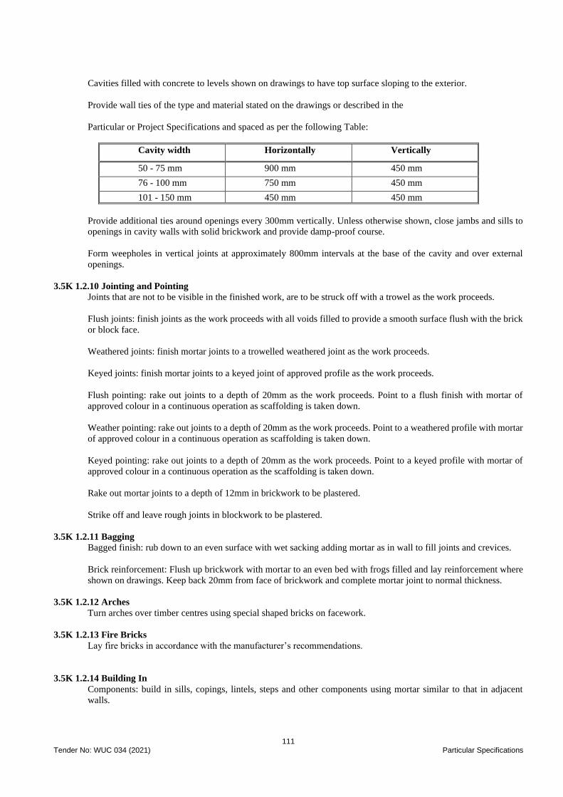
111 Tender No: WUC 034 (2021) Particular Specifications
Cavities filled with concrete to levels shown on drawings to have top surface sloping to the exterior.
Provide wall ties of the type and material stated on the drawings or described in the
Particular or Project Specifications and spaced as per the following Table:
Cavity width Horizontally Vertically
50 - 75 mm 900 mm 450 mm
76 - 100 mm 750 mm 450 mm
101 - 150 mm 450 mm 450 mm
Provide additional ties around openings every 300mm vertically. Unless otherwise shown, close jambs and sills to
openings in cavity walls with solid brickwork and provide damp-proof course.
Form weepholes in vertical joints at approximately 800mm intervals at the base of the cavity and over external
openings.
3.5K 1.2.10 Jointing and Pointing
Joints that are not to be visible in the finished work, are to be struck off with a trowel as the work proceeds.
Flush joints: finish joints as the work proceeds with all voids filled to provide a smooth surface flush with the brick
or block face.
Weathered joints: finish mortar joints to a trowelled weathered joint as the work proceeds.
Keyed joints: finish mortar joints to a keyed joint of approved profile as the work proceeds.
Flush pointing: rake out joints to a depth of 20mm as the work proceeds. Point to a flush finish with mortar of
approved colour in a continuous operation as scaffolding is taken down.
Weather pointing: rake out joints to a depth of 20mm as the work proceeds. Point to a weathered profile with mortar
of approved colour in a continuous operation as scaffolding is taken down.
Keyed pointing: rake out joints to a depth of 20mm as the work proceeds. Point to a keyed profile with mortar of
approved colour in a continuous operation as the scaffolding is taken down.
Rake out mortar joints to a depth of 12mm in brickwork to be plastered.
Strike off and leave rough joints in blockwork to be plastered.
3.5K 1.2.11 Bagging
Bagged finish: rub down to an even surface with wet sacking adding mortar as in wall to fill joints and crevices.
Brick reinforcement: Flush up brickwork with mortar to an even bed with frogs filled and lay reinforcement where
shown on drawings. Keep back 20mm from face of brickwork and complete mortar joint to normal thickness.
3.5K 1.2.12 Arches
Turn arches over timber centres using special shaped bricks on facework.
3.5K 1.2.13 Fire Bricks
Lay fire bricks in accordance with the manufacturer’s recommendations.
3.5K 1.2.14 Building In
Components: build in sills, copings, lintels, steps and other components using mortar similar to that in adjacent
walls.
112 Tender No: WUC 034 (2021) Particular Specifications
Flues: build in throat units, flue linings and terminals free from voids and restrictions parged to provide a smooth
and even flow for the flue gases.
Refuse chutes: build in as the work proceeds to provide a smooth and even interior surface free from voids and
restrictions.
Doors and windows: build in doors and window frames as the work proceeds and bed in mortar similar to that in
adjacent work.
Padstones: bed padstones in mortar similar to that in adjacent walls to give level top surface.
Wall plates: bed solid in mortar.
Airbricks: build in necessary airbricks complete with insect proof screen.
3.5K 1.2.15 Damp-proof Courses
Fill frogs and flush up brickwork to an even bed using mortar, as for brickwork, to receive horizontal flexible damp-
proof courses. Lay damp-proof course horizontally stepped up to the interior in continuous strip with 150mm laps
in length and full laps at angles. Complete joint to normal thickness.
Keep leading edge of flexible damp-proof course in facing work 10mm back from face of brickwork.
Provide flexible damp-proof course extending 100mm beyond end of lintels and sloping to weepholes over all
openings in cavity walls.
Provide flexible damp-proof course to jambs of openings in cavity walls fully lapped with horizontal damp-proof
courses at head and sill. Provide flexible damp-proof course under jointed sills turned up at back and ends.
3.6W 10 Availability of Water for Testing
The Contractor’s is responsible for making water available for filling the structures for purposes of testing for water
tightness (and where applicable disinfection).
The cost of water for initially filling each structure for one water tightness test only (and where applicable for
disinfection) will be paid for under the Contract.
The Contractor is referred to the backfilling adjacent to water retaining structures prior to the certification of the
passing of the water test in respect of the requirements of the visual inspections for leakage by the Engineer.
3.6W 11 Water Test Failure
In the event of the water test on any structure failing, the Contractor shall bear all costs connected with emptying,
the remedial works necessary to effect water tightness, refilling and retesting. The Contractor shall similarly bear
full responsibility for any delay to the Contract due to these causes.
3.7V Valves
3.7V 1 Scope
This specification covers the material and construction requirements for valves
3.7V 2 General
All valve sizes referred to in this specification are nominal bore sizes. Details or requirements on supporting
drawings or the project specification, may conflict with certain aspects of this specification, and in such cases are to
take precedence over this specification.
Lifting lugs are to be fitted on all valves, which have a mass in excess of 50kg.
The body ends of all new valves shall be sealed to prevent entry of foreign matter, prior to installation.
Each valve shall have a plate made of corrosion resistant material and securely fixed to the body by corrosion-
resistant fastenings on which the following information shall be stamped:
• The manufacturer's name
• Size of valve
113 Tender No: WUC 034 (2021) Particular Specifications
• Class of valve
• Arrow indicating the direction of flow
• The contract number
All valves shall be supplied with a manufacturer’s factory test certificate.
The corrosion protection for all valves within chambers and pump stations shall be as follows:
All exposed internal and external surfaces of the body of the valves shall be protected with a water resistant non-
toxic and non-tainting fusion bonded powder epoxy coating to a thickness of 300 microns in accordance with SANS
1217: 1984 and SANS 1274: 1979.
3.7V 3 Gate Valves
Gate valves shall be constructed according to the stipulations of the following specifications:
SANS 664: For valves operating under working pressures up to 2,5 MPa and of diameter up to 600mm. These valves
shall be constructed of cast iron.
The definitions as contained in SANS 191 and 664 are applicable to this specification.
Unless otherwise specified, valves shall have double flanged ends. The outside diameter and thickness of flanges
shall comply with the requirements of SANS 1123. Drilling patterns shall be as specified.
Unless otherwise stated, the valves are to be the non-rising spindle type in the chambers or underground and rising
spindle type in pump stations provided with a handwheel or cap top as appropriate. Spindles shall be stainless steel
and shall run in brass or bronze guides. Handwheels and cap tops shall be manufactured from cast iron.
The direction of closing shall be clockwise when viewed from above. The direction of opening and closing shall be
cast on the hand wheel or valve casing with the words "OPEN" and "CLOSED" with direction arrow respectively.
The valves shall be capable of being easily operated by one man against the maximum, unbalanced pressure, and
the effort required to operate each valve shall not exceed a torque of 150 Nm for valves 450 mm diam. and larger
and 100 Nm for valves less than 450 mm diameter. The gear ratio shall not exceed 4:1.
Class 10 and Class 16 valves are to be fitted with a means of preventing leakage past the spindle of a type specified
in SANS 664, in order to permit the re-packing of the gland while the valve is under pressure.
Valve-trim shall be either stainless steel or copper alloy. Gate seating rings may be well deposited.
The metal identification plate, permanently fixed to each valve shall also include the material designations for the
body and trim (symbols used and their sequence to be as specified in SANS 664).
The design of the valves shall be such that the cast iron/steel sections are not subject to excessive tension, by the
tightening of connecting bolts, as can happen when the faces of the bonnet and the stuffing box flanges are not fully
machined for a full faced gasket.
Bolts must be used to fasten the stuffing box to the bonnet, and the bonnet to the valve body. The use of studs is
unacceptable.
Unless otherwise stated, wedge gate valves are to be used for scouring with Resilient Seal gate valves used for
isolating, unless within the pump station stations where wedge gate ones are to be used.
Unless otherwise shown on the drawings, all valves shall be installed with a suitable dismantling joint to enable the
valve to be removed from the pipeline. The clear gap of the joint shall not be less than 15 mm. Supporting feet are
to be fitted on all valves of sizes 300mm and larger.
3.7V 4 Air Valves
Air valves shall be of a pattern and manufacture approved by the Engineer for the conditions under which they
operate. They shall be of the vacuum break type, of compact single chamber design, in addition to incorporating
“Anti-shock” feature where located within the pump stations.
The valves shall unless otherwise note will be the screw type up to and including 50mm and flanged thereafter.

114 Tender No: WUC 034 (2021) Particular Specifications
Where ordered air valves shall be fitted with ¼" BSP test cocks.
PV 5 Non-Return Valves
Reflux valves shall comply with BS. 5153 or SANS 144 and, unless otherwise noted, shall be double-flanged of the
"non-slam" type for horizontal and vertical mounting. They shall be of robust construction and suitable for the
operating head and close drop tight. General construction details shall be as described above for gate valves.
The body, cover and door shall be of the close-grained cast iron and the door shall be fitted with a zinc-free phosphor-
bronze face, closing on a corresponding bronze face in the body.
3.7V 6 Butterfly Valves
Butterfly valves shall conform to the requirements of BS 5155: 1984 and shall be cast iron solid body drilled off-
centre to enable downstream dismantling. They shall be clockwise closing when viewed from above. Operation shall
be by means of a spring loaded, quarter-turn ratchet hand lever.

115 Tender No: WUC 034 (2021) Technical Specifications – Mechanical Works
WATER UTILITIES CORPORATION
CONTRACT PART 3
SCOPE OF WORK
PROJECT SPECIFICATIONS
TECHNICAL SPECFIFICATION
FOR MECHANICAL WORKS
A WORKS CONTRACT FOR THE PROCUREMENT OF CONTRACTORS
FOR THE DESIGN, SUPPLY AND BUILD OF MAUN SATELLITE VILLAGES BULK WATER
SUPPLY INCLUDING WATER TREATMENT PLANT AT SEXAXA
TENDER REF NO: WUC 034 (2021)
MECHANICAL WORKS – PUMPS STANDRAD SPECIFICATIONS
Construction
Centrifugal pumps shall include:
• Casing with direction of rotation plate and drain plug at lowest point.
• Suction and discharge connections.
• Impeller and shaft.
• Shaft couplings as required.
• Shaft seal.
• Motor, with terminal box for flexible conduit connection.
Installations shall include:
• Suction and discharge pipe reducers.
• Expansion pieces directly connected to the pipe connections.
• Vibration isolation equipment.
• Gland drain and tail pipes arranged to discharge into an open tundish adjacent to the pump base.
• Support brackets or plinths incorporating anti-vibration material.
• Flow meters
• Pressure indicators
Pumps shall be to the following standards as applicable:
• SANS 9909
• SANS 8849
• SANS 60335
• SANS 54511
• SANS 5151
• SANS 13253
• SANS 1125
All pumps shall be electrically driven.
Pumps shall be capable of isolation and removal.
Duty and standby pumps shall have non-return valves fitted in each pump discharge. Strainers shall be fitted to inlets.
Pump connections shall be screwed to SANS 1109-1 / ISO 7 up to DN50 and flanged to BS EN 1092-3 (copper alloy)
and SANS 7005-1 (steel) flanges as applicable, PN16 for DN65 and above. Cast iron flanges shall be to SANS 7005-2.
Pump suction and discharge flanges shall be drilled and tapped for pressure gauge connections and have closing plugs.
Drive connections between motors and pumps shall be fully protected against accidental contact. Provision shall be made
for shaft speed measurement.
Tied bellows type flexible pipe couplings shall be installed at all pipework connections to pumps.
Pump sets shall be suitable for mounting on a prepared base with foundation bolts.
116 Tender No: WUC 034 (2021) Technical Specifications – Mechanical Works
Pump and piping loads shall each be independently supported.
The motor terminal box shall be suitable for flexible conduit connection.
Final pump duties shall be verified using certified resistances of system components.
Pump acceptance tests shall be to SANS 9906 / ISO 9906.
Materials
Casings, pedestals, base plates, stuffing box housings and pulleys shall be cast iron to BS EN 1561. Casings shall be fitted
with air vent and drain plugged tappings.
Impellers shall be cast iron, stainless steel, gun metal or bronze to suit the application. Impellers for hot water supply
circulators shall be bronze or stainless steel.
Shafts shall be stainless steel or carbon steel to suit the application. Stainless steel sleeves shall be fitted in the wetted
section together with mechanical seals.
High temperature hot water pumps shall have close-grained cast iron or cast steel casings, nickel iron impellers and
stainless steel shafts.
Packed glands shall not be used on variable pressure installations, or where temperatures exceed 115°C.
Bearings shall be the heavy-duty ball type. Bearings shall have a minimum life of 30,000 running hours.
The permissible service pressure of cast iron pump casings shall be in accordance with the manufacturer's
recommendations. No pump part or component part shall be subjected to a gauge pressure in excess of 16 bar.
Impellers and couplings shall be keyed to the drive shaft. Shafts shall be fitted with water deflectors.
Types of Pump
Circulating Pumps
Pumps shall be mounted on a common bedplate or steel base frame with the drive motor, except for vertical pumps, twin
pump sets and in-line types.
Drip pipes shall be extended from the gland well tapped outlet to a tundish and cleanable drain pipe system.
Belt Driven Pumps
The drive motor shall be mounted above the pump, with guarded vee-form belt drive, with a minimum of two grooves
and drive belts.
Drives shall have endless reinforced rubber type vee section belts with grooved pulleys of cast iron, or aluminium alloy
cast in one piece. A minimum of two grooves and belts shall be provided.
The motor plate shall be resiliently mounted and have means of adjustment to tension drive belts.
Direct Coupled Pumps
The pump and drive motor shall be mounted on a common cast iron bedplate and be connected with a guarded flexible
coupling. Where appropriate, back pull-out facility shall be provided.
Close Coupled Pumps
The motor and pump shall be mounted on a cast iron sub-frame and baseplate. The pump casing shall be vertically split
to provide back pull-out facility with casing parting screws.
117 Tender No: WUC 034 (2021) Technical Specifications – Mechanical Works
In-Line Pumps
Pumps shall have close-coupled motors with spindles at right angles to the pump axis. Inlet and outlet shall be in the
same plane. Units shall be suitable for horizontal or vertical mounting. Bearings shall be pre-packed type.
Casing and base shall be of cast iron or bronze. Pumps shall be mounted on a prepared base, or on wall brackets.
Twin Pumpsets
Twin pumpsets shall comprise direct-driven horizontal in-line pumps coupled together in parallel with common inlet and
outlet connections. The outlet connection shall incorporate a changeover check valve.
Semi-Rotary Hand Pumps
Semi-rotary hand pumps for emptying purposes shall be double acting with a cast iron body, steel spindle with brass wing,
brass suction divider with hinged brass flap valves. Pumps shall be mounted on a tripod and be provided with three metres
length suction and delivery hoses with suitable connectors.
Non-Submersible Sump Pumps
The materials shall be as for circulating pumps for water. Each pump shall incorporate a removable non-ferrous suction
strainer terminating at a foot valve of the same size as the pump inlet and piping. Stainless steel float switch components
shall be provided. The unit shall be complete with a totally enclosed wall mounting direct-on-line starter with no-volt
and overload protection in each phase.
The pump assembly shall be free standing on the base ring with the motor clear of the water level. Pump start and stop
levels shall be adjustable.
Submersible Pumps
Submersible pumps shall be of the single stage centrifugal type. The materials shall be as for circulating pumps for water
or may have aluminium body and GRP impeller. The squirrel cage motor shall be suitable for the building electrical
supply and submerged operation.
All studs, bolts, nuts, screws and washers shall be of stainless steel.
Each pump shall be complete with adjustable level controller, control panel, non-return valve in the discharge line and
lifting handle and chain. The control panel shall incorporate thermal overload protection with automatic reset provision.
Pressurisation Units
General
Sets shall be capable of maintaining the system design and operating conditions.
Pressurisation units shall be packaged and delivered ready for connection and commissioning.
Duplicate pumps shall have duty selection and automatic changeover facilities.
Pumps shall have suction and discharge isolating valves, pipeline strainer, and discharge check valve.
Sets shall be mounted on a mild steel base frame with lifting lugs.
Connections shall be located to allow ease of installation and be either flanged to SANS 1123 or have screwed tapered
threads to SANS 1109 / ISO 7.
A removable system fill connection shall be provided.
High- and low-pressure switches shall be manual re-set type.
Electrical terminal boxes shall be suitable for flexible conduit connection.
Safety protection shall comply with the requirements of BS 7074 . Safety/pressure relief valves shall be to BS EN ISO
4126-1.
118 Tender No: WUC 034 (2021) Technical Specifications – Electrical Works
WATER UTILITIES CORPORATION
CONTRACT PART 3
SCOPE OF WORK
PROJECT SPECIFICATIONS
ELECTRICAL WORKS
A WORKS CONTRACT FOR THE PROCUREMENT OF CONTRACTORS
FOR THE DESIGN, SUPPLY AND BUILD OF MAUN SATELLITE VILLAGES BULK WATER SUPPLY
INCLUDING WATER TREATMENT PLANT AT SEXAXA
TENDER REF NO: WUC 034 (2021)
ELECTRICAL WORKS
D1 Scope of Electrical Installation
This section includes the design, manufacture, supply, delivery, offloading, storing, if necessary, erection, painting,
commissioning, testing and maintenance during the Maintenance Period, and final handing-over of all necessary
electrical equipment (unless otherwise indicated below) which shall including the following:
Supply and installation of the feeding cables from the Botswana Power Corporation metering kiosk to the MCC.
Supply and installation of motor control centres as specified.
All control cabling associated with the installation.
Complete electrical installation in the pump house.
Complete earthing of the electrical installation.
Supply and installation of all instrumentation.
D2 Interpretations
D2.1 Application
The specifications that follow are essentially functional specifications only. The contractor shall design the various
installations and produce complete lists of equipment complying with the requirements set out below and with those
of the standard specifications listed in the Scope of Works of this document and he shall submit these to the Engineer
together with appropriate circuit diagrams for approval before commencing manufacture of the individual MCC’s.
D3 General Requirements
D3.1 Standards
All material and equipment supplied and/or installed under this Contract shall be new and of good quality and shall
comply with the requirements laid down in the latest editions of the relevant SABS, BS or IEC Specifications and
their amendments (if any) and the requirements of this specification.
In the event of items bearing the SANS/SABS mark being available in respect of the materials and equipment
required, only items bearing this mark will be acceptable. The workmanship and finish of work shall be of a high
standard throughout and to the satisfaction of the Engineer.
Similar equipment supplied under this contract must be identical in all respects and it shall be possible to interchange
any of the same equipment under this contract.
All auxiliary equipment must also be identical including items such as contactors, fuses, motors, fans, method of
wiring, numbering of wires, relays, indication lamps, instruments and other parts.
D3.2 Compliance with Law and Regulations
The work shall be carried out strictly in accordance with and all material and equipment supplied shall comply with
the following laws and regulations where applicable:
o The latest edition of the “Code of Practise for the Wiring of Premises”, SABS 0142, as amended.
o The Machinery and Occupational Safety Act (Act No. 6 of 1983) as amended.
o The “Electrical Supply Bylaws and Regulations” of the Supply Authority.
o The Local Fire Office Regulations.
119 Tender No: WUC 034 (2021) Technical Specifications – Electrical Works
o The Code of Practise for the Installation and Maintenance of Electrical Equipment used in Explosive
Atmospheres” (SABS 086).
The Contractor shall be responsible for serving all notices and paying all fees due in terms of the above laws and
regulations. Where conflict exists between any of the above regulations and the specifications, the said conflict must
be referred to the Engineer in writing for his ruling.
D3.3 Radio and TV Interference
All equipment installed under this Contract shall comply with the Government Notice No. R.2246 and any other
applicable rules and regulations in respect of radio and TV interference’s. Any equipment found producing
interference subsequent of commissioning shall be suppressed or replaced to the satisfaction of the Engineer without
any additional cost.
D3.4 Site Conditions
The electricity supply system with be a 400/230V, 50Hz, three phase, four wire system with solidly earthed neutral
and all material and equipment supplied and installed under this contract shall be rated, designed and manufactured
for satisfactory operation on this system.
It must be noted that severe voltage surges and/or spikes may be experienced on the electricity supply system due
to lighting or switching operations and where necessary the Contractor shall provide the necessary protective devices
against such surges and spikes for the equipment supplied and installed by him with special reference to electronic
devices. The following arresters shall be provided:
D3.4.1 Lightning Arresters
Transducers/Transmitters
Where transmitters require a separate power supply, in-line suppressing shall be protected as specified in the
following paragraph.
Signal Cables for Transducer/Transmitters
All signal lines entering or leaving the transmitter station cabinet shall be protected from induced or direct surges.
The coaxial lines to the ultrasonic transducers need only be protected by small gas arresters. These inputs require
protection from high voltage level surges only as they normally carry pulse signals of peak voltage greater than
200V.
In this case, low capacitance gas arresters are recommended, having a 5kA capacity (8/20 us wave shape), a DC
breakdown voltage of 450V or higher, and an impulse breakdown voltage of less than 1000V at 1 kV/us rate of
voltage rise. The arrester shall be equivalent to the SURGETECH Blitzductor No. 919 203 type or equivalent
approved by the Engineer.
• 12V or 24V Pulse, and 20MA Circuit
• 12V or 24V pulse and 20MA loop lines shall have a graded type of protection against both common mode
(both lines with respect to earth) and differential mode (between lines) surges.
All lines associated with a specific transmitter unit shall have their protective modules housed in a single box with
a common earth connection from this box to the earth bus bar. 12V or 24V pulse and 20MA loop lines shall have a
graded type of protection against both common mode (both lines with respect to earth) and differential mode
(between lines) surges.
All lines associated with a specific transmitter unit shall have their protective modules housed in a single box with
a common earth connection from this box to the earth bus bar.
LV Switchgear
Lightning arresters shall be provided for each phase in all boards, connected to each phase of the incoming cables.
Lightning arresters shall be solidly earthed directly on the main earth bar. All connections to and from lightning
arresters shall be as short and straight as possible.
D3.5 Fixing and Support Materials
120 Tender No: WUC 034 (2021) Technical Specifications – Electrical Works
All surface mounted fixing and support materials in connection with the installation of electrical material and
equipment such as cable rack, conduit, saddles, clamps, brackets, bolts, nuts, washers, and screws shall be grade
304 stainless steel.
D4 Electrical Cables, Cable Terminating Gland and Earth Wires
Low voltage cables shall be for service in a 400/230V 3 phase 50HZ system and shall be PVC insulated, steel wire
armoured, PVC sheathed, 660/1000-volt grade, complying with requirements of SANS 1507. The cores shall be
stranded copper.
All single and multi-core cables shall comply with SANS 1507 and the relevant parts as listed below:
• SANS 1507 Part 1: General, ‘Electric cables with extruded solid dielectric insulation for fixed installations
(300/500V to 1900/3300V)’
• SANS 1507 Part 2: Wiring Cables, ‘Electric cables with extruded solid dielectric insulation for fixed
installations (300/500V to 1900/3300V)’
• SANS 1507 Part 3: PVC Distribution Cables, ‘Electric cables with extruded solid dielectric insulation for
fixed installations (300/500 V to 1 900/3300 V)’
• SANS 1507 Part 4: XLPE Distribution Cables, ‘Electric cables with extruded solid dielectric insulation for
fixed installations (300/500 V to 1900/3300 V)’
• SANS 1507 Part 5: Halogen-free Distribution Cables, ‘Electric cables with extruded solid dielectric
insulation for fixed installations (300/500 V to 1 900/3 300 V)’
Cables and earth conductors for a specific applicable shall be selected strictly in accordance with the requirements
laid down in SANS 10142 in respect of current rating and voltage drop. A proper cable schedule shall be prepared
for all cables by the contractor. The format of the cable schedule must first be submitted for approval by the
Engineer.
The conductors shall be of high conductivity Copper and shall be delivered to site on cable drums with unbroken
seals bearing the SABS mark. Where applicable, cables shall have the SABS mark stamped/ embossed on the sheath.
D 4.1 Cable Termination
The earth terminal shall be connected to a dedicated ‘way’ on the earth bar or earth stud, as applicable. All cables
shall be identified at each gland and termination using appropriate labelling, as specified elsewhere. Wherever cables
pass through holes in floors and walls or enter or leave pipes or ducts in the floor, the Contractor shall seal the
opening with vermiculite plaster or other approved equivalent. The opening shall be filled for the full thickness of
the floor or wall and the filler domed or raised slightly to prevent the accumulation of water or oil in the seal.
Each cable connection shall be terminated at each end by means of suitably sized adjustable chromium plated, brass
terminating gland complete with armour clamp and neoprene shroud. Cable terminating glands for outdoor use shall
be provided with waterproofing inner seals as well as waterproofing seals or nipples. Cable armouring shall be
earthed at each end but may not be used as earth continuity conductor.
The power supply to submersible pump motors shall be terminated onto welding plug socket outlets close to the
motor. The flexible submersible cable from the motor shall then be terminated onto a plug, which plugs into this
welding plug.
All current and earth conductors shall be terminated at each end by means of a suitably sized bolted lug crimped
onto the conductor. The lugs shall be bolted onto the relevant bus bars, earth bars or earthing terminals.
Control wiring/cables shall be of a minimum thickness of 2.5 mm sq. Power cables shall be of a minimum thickness
of 4.0 mm sq. The cores shall consist of at least three strands of copper conductor unless otherwise specified.
Screened cables shall be provided for all signal cables e.g., cables for flow meters.
D 4.2 Cable Installation in trenches, sleeves
All cables to be installed by qualified personnel having the necessary skill, training and experience. Cable bend
radius to be at least twelve times the diameter of the cable over armouring. Sufficient slack to be left to relieve
stresses. All ends shall be sealed off immediately after cutting to prevent moisture absorption.
No joint will be allowed in any run of cable or earth conductor unless the route length exceeds the maximum drum
length manufactured, or unless specific permission to do so has been given by an Engineer. Should cable jointing/
splicing be deemed necessary, then jointing kits shall be Epoxy Resin moulded type and be 3M, Scotch-Guard (or
equal and approved).
121 Tender No: WUC 034 (2021) Technical Specifications – Electrical Works
The Contractors shall be responsible for the excavation, bedding, backfilling, consolidating and making good of all
cable trenches as specified in Part VIII of SANS 10198 with the exception of those sections of the cable routes
where it is specifically indicated on the accompanying drawings that open cable ducts will be provided by others.
The contractor must take care to remove any debris of foreign matter that may have fallen into the trenches during
the period between excavation and commencement of cable laying operations.
Cables in trenches shall be laid with sufficient slack to relieve stresses. The cables shall be clamped where necessary
to relieve the stress on joints of the lead sheath.
D 4.2 LV Cable Routes
Cable routes must be marked out on site by the Contractor and must be approved by the Engineer before any
excavations may commence. This arrangement is to ensure the minimum interference with paved walkways.
Should any cable routes cross any roads or railways, these crossings must be sleeved by 150mm diameter reinforced
concrete pipes which are to be supplied and installed by the Main Contractor. In each case a spare sleeve is to be
provided for possible further additions. Only one cable is to be installed in a cable pipe duct or sleeve except in the
case of very small cables if there are insufficient ducts for all cables.
D 4.3 Excavations & Trenching
Each cable shall be laid in a bedding of river sand or sifted soil 75mm over and 75mm below the cable – clayish soil
will not be accepted as bedding.
The Contractor shall, before excavations commence, familiarise himself with the route and conditions on site and it
shall be his responsibility to obtain the necessary information regarding other plant along the route and every effort
shall be made to avoid damage to this plant. The exact positioning of trenches shall be approved on site by the
Employer and/or Engineer and excavations shall not commence until approval has been received.
The cable trenches shall be excavated to a depth of 600mm below ground level for LV cables and shall not be less
than 300mm wide for one or two cables, and the width shall be increased where more than two cables are laid
together, so that the cables may be placed at least 150mm apart throughout the run. The bottom of the trench shall
be level and clear, and the bottom and sides free from rock or stones liable to cause damage to the cables.
D 4.4 Backfilling & reinstating
No cable trench shall be backfilled before the cable(s) in the trench has been inspected and approved by the Engineer.
All excavations made shall be backfilled in 150mm layers, the earth in each layer being well tamped and
consolidated and sufficient allowance made for settlement. The refilled trench shall be maintained by the Contractor,
at his expense, in a thoroughly safe condition for the duration of the Contract.
All backfilling of road crossings shall be preferably consolidated with a mechanical power-driven compactor.
Surplus excavated material shall be disposed of by and at the cost of the Contractor who shall leave the trench and
adjacent area in a clean and safe manner.
D4.5 Marking Tape
Yellow PVC marking tape, 150mm wide, with the word “Buried Electrical Cable – Caution” in both English and
Tswana, printed in Red or Black, shall be buried approximately 300mm below ground level above the cables.
D4.6 Cable Markers
Cable markers shall consist of 150mm x 100mm x 500mm high concrete blocks with 50mm high letters cast in the
concrete and marked “MV or LV Cable”. The concrete block must not protrude more than 150mm above the
finished pavement level. Cable markers are to be installed at each end, each cable through joint position at each
change of cable direction and at 50 metre intervals along the cable routes.
Cables to be installed on walls and structures shall be properly supported and rigidly fixed at suitable regular
intervals to prevent it from sagging under its own weight or snagging.
All exposed cable runs shall be installed neatly horizontally and vertically, and all exposed vertical cable runs
between ground level and 2m above ground level shall be installed in cable sleeve pipes or conduits. These pipes
or conduits shall extend to at least 300mm below ground level. Intervals between fixing points for sleeves and
conduits shall not exceed 1m.
D5.0 LV Switchgear Electrical Distribution and Motor Control Boards
122 Tender No: WUC 034 (2021) Technical Specifications – Electrical Works
D 5.1 Motor Control Boards
D5.1.1 General Performance
All electrical distribution boards and motor control board shall be IP54 enclosures constructed of at least 2mm thick
steel plate or equivalent and powder-coated in electrical orange paint. Sufficient provision shall be made for heat
dissipation and ventilation of the board.
These board shall comply with the requirements of SABS 1180: Part I where applicable. Doors shall be rigid and
shall be secured in position by means of robust grade 304 stainless steel hinges. The doors shall each be provided
with at least two lockable “square key” panel locks – one at the top and one at the bottom of the lock side of the
door. The chassis shall be rigid and facilities shall be provided on the chassis for mounting all the relevant equipment.
No equipment shall be mounted on the rear panels of boards.
The panel shall be rigid and readily removable without necessitating the disturbance of any of the equipment on the
board. Panels shall be mounted in such a way that all equipment is flush behind the panel.
Each board shall be provided with a suitably rated main isolator. All screws, studs, bolts, nuts and washers used for
these boards shall be rust proofed. The use of self-tapping screws will not be permissible.
A suitable galvanised gland plant of 3mm thickness shall be provided for termination cables. Cable entries to MCC’s
shall only be from below. All boards shall only have front access and shall make due allowance for access to the
terminations without any physical difficulties.
D 5.1.2 Motor Control Centre
The contractor shall design, supply and install Motor Control Centre for the boreholes, booster pump station and
treatment plant. The motor control centre shall be free standing, floor mounting, dust and damp protected, vermin
proof, metal enclosed multi cubicle, front access type equipped with moulded case circuit breakers and motor starters
as required for pump station, in accordance with IEC 439 and SABS 1473. The supplier shall design the switchboard
taking into consideration the following:
• Prospective short circuit current
• Ambient temperature and its effect on the raung of switchgear.
• Electrical protection discrimination.
The motor control centre shall be located indoors. The switchboard shall be suitable for operation at 400V, 3 phase,
4 wire and 50Hz system.
D 5.1.3 Colour Finish
The external colour finish of the motor control centre shall be light orange 826 to SABS 1091. The colour finish on
internal mounting plates shall be gloss white.
D 5.1.4 Busbar
The main busbar shall be of high conductivity; hard drawn copper strip adequate uniform cross section supported
on substantial insulators and adequately rated. All busbar and down droppers shall be completely screened to prevent
accidental contact therewith when the common rear access cover is removed.
Each cubicle on the MCC shall be provided with an earthing stud connected directly to a copper earth bar of suitable
cross section running the whole length of the switchboard Incomer.
The incoming breaker shall be adequately rated moulded case circuit breaker. It shall be equipped with a suitably
scaled voltmeter with phase to phase and phase to neutral selector switch, ammeter with selector switch and kilowatt
meter. Power transducer with 4 - 20mA analogue output for remote indication.
D 5.1.5 Feeder
All feeders shall be non-automatic moulded case circuit breakers and be operable from the exterior of the panel by
means of vari-depth handle or similar which is lockable in the "OFF" position.
D 5.1.6 Starter
All Motor starters shall be Electronic Soft starter type as required to comply with the specified transient volt drop
limitation, but generally shall comprise the following;
123 Tender No: WUC 034 (2021) Technical Specifications – Electrical Works
• Triple pole ON/OFF on-load isolating switch, mechanically interlocked with the front access cover. The
isolator shall be operable from the exterior of the panel by means of vari-depth handle or similar which is
lockable in the "OFF" position.
• The motor protection shall have the following as minimum requirements, thermal overload, phase
unbalance, stalling, under-load, earth fault, starting time monitor, limited start per hour and emergency
start.
• Manual/remote selector switch
• Flush fitting M.l.S.C ammeter suitably scaled
D 5.1.7 Status Indication
The following indication lights shall be mounted on the panel front: -
(i) Green Motor running
(ii) Red Motor stopped
(iii) Amber Motor tripped
Remote • Run•, "Stop” and • Fault trip" indication shall be provided via potential free auxiliary contacts.
• Running hour meter
• Starter control circuits are to be operated at 220Volts NC
• Interlocking shall be provided between duty and standby pumps
D 5.1.8 Marshalling/Control cubicle
All wiring to outgoing interlocks and field equipment shall be via a separate marshalling/control cubicle.
Distribution boards
All MCB distribution boards shall comply with SANS 60439-4/IEC 60439-4. The MCB distribution board
enclosures shall be fabricated from robust protected sheet steel and be coated with epoxy powder paint and the
finished colour to match the DFTAD preferred colour scheme. Minimum degree of protection shall be:
• In enclosed locked switchroom – IP 31
• In distribution cupboards - IP 31
• In enclosed but shared plant rooms – IP 43
• In outdoor or non-enclosed plant rooms - IP65
The busbar and all live parts shall be fully shrouded /insulated. All boards shall contain a ‘neutral’ and ‘earth’ bar
and each shall be provided with one outgoing terminal for each single way provided. All neutral and earth
connections shall be made in the same physical order as for phase connections.
Distribution boards shall incorporate a built-in isolator. The associated incoming live terminals shall be adequately
shrouded and provided with sealing covers foe all unused ways. All distribution boards and equipment enclosures
are to include hinged access to the MCB’s and supplementary equipment complete with tool operation for normal
access and provision to fit padlocks to the access covers. The padlocking arrangement shall be neat.
Circuit charts shall be provided clearly detailing all circuit numbers, area served, connected loads, device rating,
earth loop impedance, cable size and length etc. The charts shall be type written and provided with ‘clear’ envelopes
fastened to the inside cover of the board.
The distribution board shall be labelled on the front with a traffolite label indicating the distribution board reference,
number of phases, source of supply and area served. Inside the front door, adjacent to the circuit chart, a label shall
be permanently fixed indicating the earth fault impedance and fault level at the board, and the cable size and
protective device rating serving the board.
D 5.2.1 Miniature Circuit Breaker
The breakers shall comply with SANS 156 and shall bear the mark. Breakers which comply with BS 3871: Part 1,
BS 4752: Part 1, VDE 0660 and/or IEC 157 will only be considered if approved by the Supply Authority. The
minimum short circuit rating shall be as specified.
124 Tender No: WUC 034 (2021) Technical Specifications – Electrical Works
The moulded case shall be manufactured from high grade plastic material and resistant to heat, water, shocking,
arcing etc. MCBs shall be capable of being locked on the off position. Circuit breakers shall be all type C
instantaneous trip rating for general lighting and small power circuits. For motor starting of mechanical plant it shall
be type D. Operating handles of circuit breakers shall be trip free type to prevent the breaker being closed on fault
conditions. Breakers shall be clearly labelled to indicate associated voltage and current rating.
D 5.2.2 Residual Current Devices-Earth Leakage units
Additional protection shall be provided by means of an RCD with a rated residual current not exceeding 30mA and
an operating time not exceeding 40ms in accordance with regulation 415.1.1 BS 7671 IET Wiring regulations.
These shall be provided for;
• Socket outlets with a rated current not exceeding 20A that are for use by ordinary persons and are intended
for general use.
• Mobile equipment with a current rating not exceeding 32A for use outdoors.
Operating mechanisms shall be quick make, quick break, over centre type which are trip free. The contact position
shall be positively indicated. All poles shall open, close and trip simultaneously.
Tripping characteristics shall incorporate inverse definite minimum time overcurrent and instantaneous functions
and shall be consistent with the circuit breaker mounted in any position. RCD’s shall be capable of detecting
pulsating d.c fault currents.
D 5.2.3 Internal Wiring for Switchboards and Motor Control Boards
The internal wiring of the boards shall consist of colour PVC insulated conductors of adequate copper cross-section
but minimum of 1,5 mm sq., which shall be neatly installed horizontally and vertically and grouped and installed in
wire ways. Only spiral binds to be used (string will not be acceptable). Numbers of an approved type shall be
provided on each end of each wire, to facilitate the tracing of circuits in accordance with the manufacturers wiring
diagram. Wiring shall be fitted with lugs before terminating onto equipment on terminals. Wiring of external circuits
shall be terminated on suitably sized DIN rail.
Only Hexagon crimping allowed.
D 5.3 Labelling of Switchboards and Motor Control Boards
Labels of the black with white lettering “trefolite” type shall be provided below each item of equipment on the front
panel of each board as well as on the chassis near the relevant equipment to identify such equipment in English in
6mm high lettering. Each distribution board or motor control board shall be provided with all the necessary
equipment to ensure proper functioning of the plant controlled by it.
All safety warning notices shall be in English and the lettering shall be red on a white background.
D5.4 Equipment for Distribution Boards and Motor Control Boards
The Contractor must provide a fully functional system. The equipment shall comply with the specifications below
where applicable.
All contactors for the MCC’s shall be of the electromagnetic operated air break type with 220V AC coil voltage.
The 220V control voltage shall be supplied from a earth leakage unit suitable for inductive loads. Category A3
contactors shall be used.
D 5.5 Distribution and Control Board Components
D 5.5.1 Isolator
All isolators shall be of the “Load-breaking” and “fault making” type and shall comply with the requirements of BS
5419-1977 and SABS 142 where applicable. The fault level of the isolators shall be equivalent to or higher than the
fault level at the associated bus bar or incoming cable.
D 5.5.2 Moulded Case Circuit Breaker
All moulded case circuit breakers shall comply with the requirements of SABS Specification No. 156-1977
manufacture with a rupturing capacity equivalent to or higher than the fault level at the associated bus bar or
125 Tender No: WUC 034 (2021) Technical Specifications – Electrical Works
incoming cable. These circuit breakers shall be fitted with copper terminal collector bars where more than one cable
tail has to be terminated on the same terminal.
D 5.5.3 Air break Contactors
All contactors shall be of the totally enclosed three pole, double air break per pole, automatic magnetic type
complying with the requirements of SABS 1092 and/or IEC 158-1 for Class AC 3 contactors of Intermittent Duty
Class 0,3. The contactors shall be rated for a least 130% of the associated load current.
All contactors shall be provided with arc extinguisher and readily replaceable silver or silver-alloy contacts rated
for 2-million “on” and “off” switching operations at rated current. All contactors shall be capable of carrying and
making and breaking at a recovery voltage of not less than 90% of the system voltage. Each contactor shall be
provided with a closing coil suitable for continuous operation and at least 15 closing operations per hour.
At least two normally open and two normally close auxiliary contacts shall be fitted. The contactor may not hum
or chatter in service and the contacts may not bounce on closing.
D 5.5.4 Current Transformers
All current transformers shall be of the air insulated type complying in all respects with the requirements laid down
in BS 3938: 1973 and/or IEC 185. The Contractor shall carefully select the ratio, burden and accuracy class to suit
its specific application in accordance with the recommendations and requirements of BD 3938 and/or IEC 185.
D 5.5.5 The following classes of current transformers shall be used:
General Protection (over-current/thermal overload) 10P15
Differential Protection X
kVA, kW, kWh meters and ammeters 0.5
D 5.5.6 Indicating Instruments
All indicating instruments shall comply with the requirements laid down in BS 89: Part I: 1970 for instruments of a
2.5 Accuracy Class. All indicating instruments shall have 96 mm sq. dials. The maximum demand ammeters shall
be of the 6 Amp combined maximum demand registering and instantaneous indicating type having MISC movement
and thermal demand indication with an integrating time lag of 15 minutes. The ammeter scales shall be direct reading
with a full-scale deflection corresponding to 120% of the rated primary current of the relevant current transformer.
Each ammeter shall be clearly and indelibly marked to indicate the colour of the phase to which it is connected.
Maximum demand ammeters must be installed on all incomer panels (1 per phase).
Voltmeters shall be of the direct reading moving iron suppressed zero type and shall be provided with a 7-position
selector switch to select between line voltages, phase voltages and off position.
The running hour meters shall have cyclometer dials indicating up to 6 digits and shall not be MISC resettable.
D5.6 Information to be submitted by the successful tenderer in respect of all boards
The Contractor shall submit three paper prints of each of the following drawings, in respect of each of the boards to
the Engineer for approval prior to manufacture:
• Outline and general arrangements drawings showing main overall dimensions and construction details;
• A wiring diagram; and
• A schematic line diagram.
D5.7 Testing of distribution/motor control boards at the manufacturer’s works
Each distribution/motor control board shall be subjected to the following tests in the manufacturer’s works after
manufacture:
• A thorough inspection shall be carried out to ensure compliance with the specification and approved
drawings and wiring diagrams and to ascertain that all connections are properly made.
• A high voltage test on all primary connections to check the insulation between phases mutually and between
each phase and earth.
• The polarities and rations of all potential and current transformers shall be checked.
• Primary and secondary injection tests shall be carried out on all switching, protection, metering,
interlocking and indication circuits.
126 Tender No: WUC 034 (2021) Technical Specifications – Electrical Works
The manufacturer shall submit three copies of test certificates giving details of conditions and results of tests carried
out to the Engineer.
D5.8 Testing and Commissioning of Distribution/Motor Control Boards after installation on site
After installation on site, but prior to commissioning, the following inspections and tests shall be performed on each
distribution/motor control board:
• Check all components to ensure that they are free from dust and protective packing material;
• Check the operation of all components liable to damage in transit such as meters and protection relays;
• The insulation of all primary circuits between phases mutually and between each phase and earth shall be
measured;
• All fuse links shall be checked for electrical continuity; and
• All control supplies shall be checked.
• All adjustable protection devices shall then be set and the boards commissioned all in consultation with
and to the instruction of the Engineer.
D5.9 Labelling Standards
All equipment must be clearly marked with a unique number. Markings must if possible always be installed in such
a way that it can be read from left to right and from the bottom upwards. Standard double terminals must be marked
in the back row from left to right and then further on at the front row from left to right.
Double terminals used for analogues must be marked from left front to left back incrementing to the right. All
terminals must be marked in numerical sequence. No other markings are allowed except in the MCC panels where
the control supply for the bus bars are marked L and N.
All wiring must be marked according to the equipment they are connected to. This includes all screen wires.
Labelling as follows:
• Equipment – Black background (9mm wide) with white lettering (5mm).
• Wiring – Yellow background with black lettering.
• Cables – Yellow background with black lettering.
D6 External Control and Sensing Units Association with Electrical Distribution Boards and
Control Boards D6.1 Level Sensors
Type of level control shall be determined by the specific requirement for the installation. Type to be confirmed by
the Engineer.
General
The level sensor shall stop the pumping cycle when the water reaches the pre-set low level. The starting cycle of
the pump shall only start again after the recovery of the borehole to a pre-set level.
Alternative 1
The level sensors shall be installed for the monitoring of the borehole water levels and for pump control. The water
pilot shall be a hydrostatic level sensor with various measuring ranges for water applications. A digital and analogue
process display complete with 2 limit contactors and 2 control contacts shall be installed in the MCC. The level
sensor (water pilot) shall be powered from the processor in the MCC. The supplier shall be responsible for the final
commissioning and calibration of the level sensors. It will however be the Contractors responsibility to co-ordinate
all tests and the commissioning.
Alternative 2
Electronic level control relay complete with probes.
D6.2 Flow Switches
Flow switches shall be installed at each borehole at appropriate positions by means of one-inch BSP nipple. The
flow switches shall be connected to the MCC panels with 2.5 mm2 x 3 core PVC/SWA/PVC cable. Provision shall
be made to prevent unnecessary trips due to surges in the water line.
D6.3 Pressure Control
General
127 Tender No: WUC 034 (2021) Technical Specifications – Electrical Works
The pressure switches shall be installed in conjunction with the necessary relay units and adjustable timers to prevent
unnecessary stop/start operations and trips from high pressure surges at start up.
Pressure Switches
Industrial type pressure switches shall be installed at each pump station. The pressure switches shall comply to the
following:
• High accuracy – Optimum repeatability of 1% of full operating range.
• Adjustable dead band – Maximum full range, minimum approximately 7% of full operating range.
• Fixed dead band – Approximately 3% of full operating range.
• Externally visible pressure scales in PSI and bars.
• External adjustable not.
• Separate electrical chamber for pressure and adjusting chamber.
• Withstand high surge pressures.
• Vibration resistant.
The pressure switches shall be connected to the MCC panels with 2.5 mm2 x 3 core PVC/SWA/PVC cable. Pressure
switches to be selected to work within the parameters of the complete water system.
D7 Cable containment and Support systems
Standards
All work shall meet all the requirements of national and local authorities and shall be in accordance with the latest
editions of the following, and any other relevant standard, in so far as they apply to the work.
Fixing materials
General
It is the responsibility of the Contractor to position and securely fix conduits, ducts, cables and cable channels,
switchboards, fittings and all other equipment or accessories as required for the Installation. The Contractor shall
provide and fix all supports, clamps, brackets, hangers and other fixing materials. Clamps and brackets used to fix
or support equipment such as cable trays, ducts, etc. shall be of a purpose-made type suitable for the specific
application.
D7.1 Finishing
Supporting steelwork, brackets, rods, clamps, etc. shall be galvanized in accordance with the requirements of SANS
14713. Where unavailable, unpainted supporting steelwork installed by the Contractor shall be wire brushed and
given one coat of rust-resisting prime, followed by one coat of high-quality enamel paint before any other equipment
is fixed.
D7.2 Structural steel
Supports, brackets, hangers, etc. may only be welded to structural steel members where prior permission of the
Structural Engineer and/or Principal Contractor has been obtained. Where welding has taken place the Contractor
shall make good the corrosion protection coatings by approved local treatment of the welded areas. "CADDY" or
similar fasteners may be used as an acceptable alternative to fix equipment to structural steel members.
D7.3 Screws & Bolts
Where holes exist in equipment to be fixed, bolts and fixing screws as specified shall be used. Where sizes are not
specified, the largest bolt or screw that will fit into the hole shall be used.
D7.4 Wall plugs
Where the fixing holes in brick or concrete walls are smaller than 10 mm diameter and where the mass of the
equipment is less than 10 kg, wall plugs may be used to fix conduits, cables and other equipment. Fibre or plastic
plugs shall be used. Wooden plugs are not acceptable. Aluminium plugs may be used in face bricks. Plugs installed
in joints between bricks are not acceptable. A masonry drill of the correct size shall be used to drill holes for plugs.
Round-headed screws of the correct diameter to match the specific plug shall be used throughout.
128 Tender No: WUC 034 (2021) Technical Specifications – Electrical Works
D7.5 Anchor Bolts
Where the fixing holes are 10 mm and larger or where the mass of the equipment is greater than 10 kg, equipment
shall be fixed by means of expanding anchor bolts or by means of bolts cast into the concrete or built into walls.
Expansive fixings are not suitable for use in certain structural members and in positions close to the edge of the
structure.
It is the Contractor's responsibility to obtain permission from the Structural Engineer and/or the Principal Contractor
prior to the use of this type of fixing.
D7.6 Galvanised Equipment
Brass screws, bolts and nuts shall be used to fix galvanized equipment.
D7.7 Short Fired Fixing
Materials such as metal cable ducts or channels may be fixed against walls and concrete slabs by means of shot-
fired fixings provided that this means of fixing is acceptable to the Structural Engineer and /or the Principal
Contractor responsible for the structure. It shall be the Contractor's responsibility to ascertain whether this method
of fixing will carry the weight of the material including conductors, cables and other items of equipment to be
installed later. Should it be found that the method of fixing is inadequate and supports tend to loosen, the Contractor
will be required to fix the material by an alternative method to the satisfaction of the Engineer.
Where the shot-fired method is used, warning signs shall be placed at all entrances leading to the area where this
work is in progress. The Contractor shall take all reasonable precautions to prevent accidents and shall always adhere
to the requirements of the Manpower and Occupational Safety Act. Nails and explosive charges recommended by
the manufacturer shall be used throughout.
D 8. General Requirements for Conduit installation
General
All accessories such as boxes for socket-outlets, switches, lights, etc. shall be accurately positioned. It is the
responsibility of the Contractor to ensure that all accessories are installed level and square at the correct height from
the floor, ceiling or roof level as specified. It shall be the responsibility of the Contractor to determine the correct
final floor, ceiling and roof levels. Draw-boxes shall not be installed in positions where they will be inaccessible
after completion of the installation. Draw-boxes shall be installed in inconspicuous positions to the approval of the
Engineer and shall be indicated on the "as built" drawings.
Galvanized steel draw-wires shall be installed in all un-wired conduit, e.g., conduits for future extensions, telephone
installations and other services.
A maximum of two 90E bends or the equivalent displacement will be allowed between outlets and/or boxes. Draw-
boxes shall be installed at maximum intervals of 15m in straight runs. All bends shall be made without heating the
conduit or without reducing the diameter of the conduit. The inside radius of a bend shall not be less than three times
the outside diameter of the conduit.
Where more than one socket-outlet is connected to the same circuit, the conduit shall be looped from one outlet box
to the following on the same circuit. Where a metal channel is used, the conduit may be installed from the channel
directly to the outlet box on condition that the conductors can be looped from one outlet to the next without making
any joints in the wires.
Where the conduit end is used to support luminaires, a ball-and-socket type lid shall be fitted to the pendant box in
all cases where the conduit is longer than 500 mm. In all other cases a dome lid may be used. Where luminaires are
specified which are fixed directly to the pendant box, the pendant box shall be fixed independently of the conduit
installation except where the pendant box is cast into concrete.
129 Tender No: WUC 034 (2021) Technical Specifications – Electrical Works
The edges of the flush mounted outlet boxes shall not be deeper than 10 mm from the final surface. Spacer springs
shall be used under screws where necessary.
All excess holes in draw-boxes or other conduit accessories shall be securely blanked off by means of brass plugs
to render the installation vermin proof.
Care shall be taken to prevent debris or moisture from entering conduits during and after installation. Conduit ends
shall be sealed by means of a solid plug which shall be screwed to the conduit end. Conduits shall be cleaned and
swabbed to remove oil, moisture or other debris that may be present before conductors are installed. Swabs shall
not be attached to the conductors.
Each length of conduit shall be inspected for defects and all burrs shall be removed. All conduits that are split,
dented or otherwise damaged or any conduits with sharp internal edges shall be removed from site. The Contractor
shall ensure that conduits are not blocked.
To ensure that all electrical conductors are easily withdrawable from conduits and to ensure that there are no joints
in the conductors, the Engineer will have the right to have the conductors of any circuit removed at his discretion.
If the conductors are found to be in a satisfactory condition after having been withdrawn, the Employer shall bear
the cost of withdrawing and re-installing such conductors. If the conductors are found to have been damaged during
installation or removal or if joints are found, they shall be replaced and the cost shall be borne by the Contractor.
D 8.1 Installation in concrete
In order not to delay building operations, the Contractor shall ensure that all conduits and accessories which are to
be cased in concrete are placed in position in good time. The Contractor or his representative shall be in attendance
when the concrete is cast.
Draw-boxes, expansion joints and round ceiling boxes shall be installed where required and shall be neatly finished
to match the finished slab and wall surfaces. Ceiling draw-boxes shall be of the deep type. In hollow tile slabs, rear-
entry draw-boxes shall be used. In columns where flush mounted draw-boxes are installed, the conduits shall be
offset from the surface of the column immediately after leaving the draw-box.
Elbows for conduits of 32 mm diameter and smaller and sharp bends will not be allowed in concrete slabs.
Draw boxes and/or inspection boxes shall, where possible, be grouped together under a common approved cover
plate. The cover plate shall be secured by means of screws.
All conduits shall be installed as close as possible to the neutral axis of concrete beams, slabs and columns. The
conduits shall be rigidly secured to the reinforcing to prevent movement towards the surface of the concrete.
All conduits, draw-boxes etc., shall be securely fixed to the shuttering to prevent displacement when concrete is
cast. Draw-boxes and outlet boxes shall preferable be secured by means of a bolt and nut installed from the back of
the box through the shuttering. Fixing lugs may also be used to screw the boxes to the shuttering. Wire will not be
accepted for securing boxes to the shuttering where off-shutter finishes are required. Where fibreglass shuttering is
used by the Main Contractor, the equipment shall be fixed to the steel only and no holes shall be drilled or made in
shuttering. All draw-boxes and outlet boxes shall be plugged with wet paper before they are secured to the shuttering.
Conduits will not be allowed in concrete floor slabs of boiler rooms (or boiler houses), laundries or other damp
areas. All socket-outlets and three phase outlets in damp areas shall be supplied from above with galvanized conduit
and accessories.
As far as possible, conduits shall not be installed across expansion joints. Where this is unavoidable a conduit
expansion joint shall be provided.
The installation of conduits in floor screeds shall be kept to a minimum. Where conduits are installed in screeds, the
top of the conduit shall be at least 20 mm below the surface of the screed. Where the screed is laid directly on the
ground, galvanized conduits shall be used. This ruling will always be applicable to the lowest floor or a building. A
minimum distance of twice the outside diameter of the conduit shall be left free between the adjoining conduits.
130 Tender No: WUC 034 (2021) Technical Specifications – Electrical Works
Conduits shall be secured to the concrete slab at intervals not exceeding 2,0m. The Contractor shall ensure that
conduits are not visible above the screed where the conduits leave the screed.
All draw-boxes, conduits, etc., which are installed in concrete shall be cleaned with compressed air and provided
with draw-wires two days after removal of the shuttering. Errors that occurred during the installation of the conduits,
or any lost draw-boxes, or blocked conduits shall be immediately reported to the Engineer by telephone and
confirmed in writing in order that an alternative route can be planned and approved by the Engineer before the
additional concrete is cast. Any additional cost shall be to the Contractor's account.
D 8.2 Surface Installations & Installation in Roof Spaces
All conduits shall be installed horizontally or vertically as determined by the route and the Contractor shall take all
measures to ensure a neat installation. Where conduits are to be installed directly alongside door frames, beams, etc.
that are not true, conduits shall be installed parallel to the frames, beams, etc.
Conduits shall be firmly secured by means of saddles and screws and in accordance with SABS 0142. Where saddles
are used to secure vertical lengths of conduit connected to surface mounted switch boxes or socket-outlet boxes, the
saddles shall be spaced so that the intervals between the box and the first saddle, between any two successive saddles
and between the last saddle and the ceiling or roof are equidistant. Conduits shall be secured within 150 mm before
and after each 90E bend.
Joints will only be allowed in surface conduit lengths exceeding 3,5m. Threads shall not be visible at joints of
completed installations, except where running joints are used. Running joints will be allowed only when absolutely
necessary. All running joints shall be provided with locknuts and shall be painted with red lead immediately after
installation.
Inspection bends or tee pieces shall not be used. Non-inspection type bends may be used in the case of 32 mm or 50
mm diameter conduits. All draw-boxes supporting luminaires or other equipment shall be fixed independently of
the conduit installation.
Where an offset is required at conduit terminations or cross-overs, the conduit shall be saddled at the offset. Conduit
routes shall be carefully planned to avoid cross-overs. Where a cross-over is inevitable, one conduit only shall be
offset to cross the other. Cross-overs shall be as short as possible and shall be uniform. Alternatively, cross-overs
shall be installed in purpose-made boxes. This method shall be employed on face brick walls and in other
circumstances where required by the Engineer.
Parallel conduit runs shall be equidistant and saddles shall be installed in line. Alternatively, a special clamp can be
used to secure all conduits in unison. In the case of conduits of different diameters, the latter method shall only be
used if a purpose-made clamp designed to accommodate the various conduit sizes is provided.
All surface mounted conduits and accessories shall be painted with a high-quality enamel paint or as otherwise
specified. The colour shall comply with the colour code specified for the installation or where no code has been
specified, shall match the colour of the surrounding finishes.
In open roof spaces (no ceiling) conduits shall run along the wall plates and the rafters. The installation of conduits
suspended between the rafters is not acceptable.
Conduits in roof spaces shall be installed parallel or at right angles to the roof members and shall be secured at
intervals not exceeding 1,5m by means of saddles screwed to the roof timbers.
Nails or crumpets will not be allowed.
Under flat roofs in false ceilings or where there is less than 900 mm clearance, or in instances where the ceilings are
insulated with glass, wool or other insulating materials impeding access, the conduits shall be installed in such a
manner as to allow for all wiring to be executed from below the ceilings.
Conduit runs from distribution boards shall terminate in fabricated sheet steel draw-boxes installed directly above
or in close proximity to the boards.
131 Tender No: WUC 034 (2021) Technical Specifications – Electrical Works
Spare conduits covering the total number of spare ways of switchboards, shall be provided between the boards and
the roof trays.
Only approved plugging materials such as fibre plugs or plastic plugs, etc., and round-head screws shall be used
when fixing saddles, switches, plugs, etc., to walls. Wood plugs are not acceptable nor should plugs be installed in
joints in brick walls.
D 8.3 Future Extensions
Conduits intended for future switches and socket-outlets, shall terminate 40 mm above the tie beams in roof spaces
with more than 900 mm free space. The conduit ends shall be threaded and fitted with a coupling and brass plug.
Conduit ends shall protrude 150 mm from the concrete to facilitate the installation of future extensions above, below
or to the side of the concrete slabs. All these conduits shall be connected to a draw-box which is cast into the concrete
within 2m of the end of the concrete. Conduit ends shall be threaded and fitted with a coupling and brass plug. In
cases where holes cannot be drilled through the shuttering to accommodate the conduit end, a deep draw-box with
rear entry may be placed over the conduit end.
Unused boxes for switches and socket-outlets shall be covered with metal cover plates. Unused boxes for luminaires
shall be covered with round galvanized metal cover plates which fit tightly against the finished surface. The cover
plate shall overlap the outlet box to mask damaged edges of the structure.
Galvanized conduit shall be installed at all free ends intended for future extensions. The conduit shall be treated
with a paint which will prevent corrosion and white rust.
D 8.4 Expansion Joints
Where conduits cross expansion joints in the structure, approved draw-boxes which provide a flexible connection
in the conduit installation shall be installed.
The draw-box shall be installed adjacent to the expansion joint of the structure and a conduit sleeve, one size larger
than that specified for the circuit, shall be provided on the side of the draw-box nearest the joint. The one end of the
sleeve shall terminate at the edge of the joint and the other shall be secured to the draw-box.
The circuit conduit passing through the sleeve shall be terminated 40 mm inside the draw-box and in the case of
metallic conduit, the conduit end shall be fitted with a brass bush. The gap between the sleeve and the conduit at the
joint shall be sealed with "Pratley Tic-Tac" or equal sealing compound, to prevent the ingress of wet cement. In the
case of metallic conduit, an earth clip shall be fitted to the conduit projection inside the draw-box and the conduit
bonded to the box by means of 2,5 mm² bare copper earth wire and a brass bolt and nut.
The end of the other circuit conduit shall be secured to the draw-box by means of locknuts and a brass bush in the
case of screwed metallic conduit or a standard bushed adaptor for other conduit types. In addition to an earth wire
which may be specified for the circuit, a 2,5 mm² bare copper wire shall be provided between the first conduit box
on either side of the joint in the case of metallic conduit. The conduit boxes shall be drilled and tapped and the earth
wire shall be bonded to the boxes by means of lugs and brass screws.
Suitable steel cover plates shall be screwed to draw-boxes installed along the expansion joint. The cover plates shall
be installed before the ceilings are painted.
Where a number of conduits are installed in parallel they shall cross the expansion joint of the structure via a single
draw-box. Several draw-boxes adjacent to each other will not be allowed.
D 9 Metallic Conduit Installations
D 9.1 Material
132 Tender No: WUC 034 (2021) Technical Specifications – Electrical Works
All conduits shall be screwed heavy gauge solid drawn steel in conformity with SABS 162-1978 or as amended. No
conduit having a diameter of less than 20mm shall be used. Otherwise, the size of all conduits shall conform to Table
4 of the Code of Practice for the number and size of conductors to be accommodated.
D 9.2 Routing
Conduits shall be fixed to the surface of walls and ceilings or concealed as specified on the drawings. The Contractor
shall agree all conduit runs with the Engineer where these are not clearly defined on working drawings. For surface
work conduits shall be securely fixed to walls and ceilings at intervals not exceeding 2 000 mm by means of single
or multiple distance saddles to give not less than 6mm clearance between conduit and wall. No solid conduit shall
pass through expansion joints. At these positions watertight flexible tubing shall be used between adaptable boxes
with all necessary earth bonding.
The conduit system shall be carefully planned and erected to avoid all unnecessary bends, cross-overs or changes in
direction. Conduits shall be laid in straight horizontal and vertical lines with easy sets. Where several conduits follow
similar routes, they shall be neatly grouped in multiple runs. Particular attention shall be paid to surface conduit runs
to ensure that the appearance and running of the conduit system harmonizes with architectural features of the
building. Where multiple runs change direction the radii of the sets shall be laid out from a common centre. Where
draw-in boxes or right-angle changes of direction are required in multiple runs, adaptable boxes shall be used.
D 9.3 Fixing
All conduit fixings and accessories shall be secured by means of Rawlplugs or as specified. Where permission of
the Structural Engineer has been obtained in writing, M6-threaded Hilti-type explosive fixings may be used complete
with purpose-made female-threaded conduit saddles.
Where conduits are required to pass in or out of ducts or from the inside to the outside of the buildings, free
circulation of air between the conduit systems of each section shall be prevented by the insertion of a conduit box
in an approved position, such box to be filled with a non-setting plastic compound after the cables have been drawn
in.
Conduit shall be mechanically and electrically continuous, tightly screwed between the various lengths so that they
butt at the socket joints and against the shoulder provided in the conduit boxes. The end of conduit shall be smooth,
free from burrs and other defects. The conduit shall be screwed just sufficiently for a joint to be made in this manner
without exposing the threads. Open ends shall be fitted with a socket and hexagon brass male bush.
Enamel or rust shall be removed from threads when installing conduit and after the joint has been made it shall be
sealed externally by means of a protective compound.
D 9.4 Accessories
Manufactured bends, elbows and tees shall not be installed except in certain cases with the approval of the Engineer.
Bends or sets shall be made cold without alteration to the section. The inner radius of bends shall not be less than
two and a half times the outside diameter of the conduit or four times the diameter of the largest cable within the
conduit.
Where conduit drops to lighting fittings exceeds 300mm the conduit shall be fitted with a dome cover having a ball
and socket joint and shall be complete with earth bonding connection.
Conduit boxes or other fittings shall be fixed to steelwork with metal clips of adequate section. Details of fixing
shall be agreed with the Engineer before commencement of work. All conduit boxes to which fittings and wall
brackets are attached shall be fixed by substantial metric cheese head screws so that the weight of the fittings is not
taken by the conduit.
Conduit accessories shall comply in all respects with SABS 162-1978. Boxes for 20mm and 25mm conduit shall be
of the circular pattern, above this they shall be of the oblong pattern and shall be malleable cast iron or galvanized
as specified.
133 Tender No: WUC 034 (2021) Technical Specifications – Electrical Works
A standard draw-in box or inspection fitting shall be included in every three lengths of conduit, which shall not
contain more than two right angle bends or the equivalent; where conduits are laid in roof or floor screeds "loop in"
boxes shall be finished flush with the ceiling or floor.
D 9.5 cabling of Conduits
Cables shall not be drawn in for any circuit until the conduits of the particular circuit is complete. Conduit runs shall
not be dismantled for wiring.
The conduit system is to be completed and tested for continuity to the satisfaction of the Engineer before cables are
drawn in. The resistance measured throughout must not exceed 0,5 ohm or 50% of the conductivity of the largest
conductor routed through the conduit, whichever is the lesser value.
Great care shall be exercised when pulling cables into conduits to ensure that no crossed cables are allowed to enter
the conduits. At all draw-boxes, sufficient cable shall be left to allow an easy sweep from one conduit entrance to
another. All cables shall be drawn in after the erection of the complete conduit system. Draw wires, tapes or cables
shall not be threaded in at the time that the conduits are installed.
Cables of a.c. circuits installed in a conduit system shall always be so bunched that the cables of all phases and the
neutral conductor (if any) are contained in the same conduit.
D 9.6 Weatherproof & Buried Installations
Conduits buried in cement plaster shall be galvanized. During erection of galvanized conduit, all threads shall be
painted with an approved metallic paint to prevent rusting of exposed threads. Vice marks or other defects shall be
similarly treated.
Conduits and fittings, for weatherproof installations or when specified on drawings, shall be welded, galvanized
with weatherproof heavy pattern drawn-in screwed and adaptable boxes with fixing lugs. Distance saddles shall be
used to space the conduits 6mm from surface to which they are fixed.
Conduits and cables are to be installed in vertical and horizontal runs. Diagonal runs of conduit or cable will not be
permitted in any part of the installation. Conduits shall be further treated with two coats of bitumen paint after
installation.
D10 Plastic Conduit Installations
D 10.1 Material
All conduits shall be SABS approved PVC conduit. No conduit having a diameter of less than 20 mm shall be used.
Otherwise, the size of all conduits shall conform to Table 4 of the Code of Practice for the number and size of
conductors to be accommodated.
D 10.2 Routing
Conduits shall fixed to the surface of walls and ceilings or concealed as specified on the drawings. The contractor
shall agree all conduit runs with the Engineer where these are not clearly defined on working drawings. For surface
work conduits shall be securely fixed to walls and ceilings at intervals not exceeding 1 500 mm by means of single
or multiple distance saddles to give not less than 6 mm clearance between conduit and wall. No solid conduit shall
pass through expansion joints. At these positions watertight flexible tubing shall be used between adaptable boxes.
The conduit system shall be carefully planned and erected to avoid all unnecessary bends, crossovers or changes in
direction. Conduits shall be laid in straight horizontal and vertical lines with easy sets. Where several conduits
follow similar routes, they shall be neatly grouped in multiple runs. Particular attention shall be paid to surface
conduit runs to ensure that the appearance and running of the conduit system harmonises with the architectural
features of the building. Where multiple runs change direction the radio of the sets shall be laid out from a common
134 Tender No: WUC 034 (2021) Technical Specifications – Electrical Works
centre. Where draw-in boxes or right-angle changes of direction are required in multiple runs, adaptable boxes shall
be used.
D 10.3 Fixing
All conduit fixings and accessories shall be secured by means of Rawlplugs or as specified. Where permission of
the Structural Engineer has been obtained in writing, M6-threaded Hilti-type explosive fixings may be used complete
with purpose-made female-threaded conduit saddles.
Great care shall be exercised when pulling cables into conduits to ensure that no crossed cable are allowed to enter
the conduits. At all draw-boxes, sufficient cable shall be left to allow an easy sweep from one conduit entrance to
another. All cables shall be draw in after the erection of the complete conduit system. Draw wires, tapes or cables
shall not be threaded in at the time that the conduit are installed.
Cables of a.c. circuit installed in a conduit system shall always be so bunched that the cables of all phases and the
neutral conductor (if any) are contained in the same conduit. Where conduits are required to pass in or out of ducts
or from the inside to the outside of the buildings, free circulation of air between the conduit systems of each section
shall be prevented by the insertion of a conduit box in an approved position, such box to be filled with a non-setting
plastic compound after the cables have been drawn in.
Conduit shall be watertight, mechanically continuous, carefully glued between the various lengths so that they butt
at the socket joints and against the shoulder provided in the conduit boxes. The end of conduit shall be smooth, free
from burrs and other defects. Open ends shall be fitted with male adaptors.
D 10.4 Accessories
Manufactured bends, elbows and tees shall not be installed except in certain cases with the approval of the Engineer.
Bends or sets shall be made cold using a suitable bending spring to ensure that there is no alteration to the section.
The inner radius of bends shall not be less than two and a half times the outside diameter of the conduit or four times
the diameter of the largest cable within the conduit.
Where conduit drops to lighting fittings exceeds 300 mm, the conduit shall be steel and fitted with a steel dome
cover having a ball and socket joint and shall be complete with earth bonding connection.
Conduit boxes or other fittings shall be fixed to steelwork with metal clips of adequate section. Details of fixing
shall be agreed with the Engineer before commencement of work. All conduit boxes to which fittings and wall
brackets are attached shall be fixed by substantial metric cheese head screws so that the weight of the fittings is not
taken by the conduit.
Conduit accessories shall comply in all respects with SANS 950. Boxes for 20 mm and 25 mm conduit shall be of
the circular pattern, above this they shall be of the oblong pattern.
D 10.5 Cabling of Conduits
Cables shall not be drawn in for any circuit until the conduits of the particular circuit is complete. Conduit runs shall
not be dismantled for wiring.
The conduit system is to be completed and tested for continuity to the satisfaction of the Engineer before cables are
drawn in. The resistance measured throughout must not exceed 0,5 ohm or 50% of the conductivity of the largest
conductor routed through the conduit, whichever is the lesser value.
Great care shall be exercised when pulling cables into conduits to ensure that no crossed cables are allowed to enter
the conduits. At all draw-boxes, sufficient cable shall be left to allow an easy sweep from one conduit entrance to
another. All cables shall be drawn in after the erection of the complete conduit system. Draw wires, tapes or cables
shall not be threaded in at the time that the conduits are installed.
135 Tender No: WUC 034 (2021) Technical Specifications – Electrical Works
Cables of a.c. circuits installed in a conduit system shall always be so bunched that the cables of all phases and the
neutral conductor (if any) are contained in the same conduit.
D11 Metal Trunking & Accessories
D 11.1 General
Metal trunking shall be of an approved type as agreed by the Engineer. The Contractor shall submit detail drawings
for the approval of the Engineer before putting the work in hand.
All trunking systems other than underfloor ducting shall be designed with 20% spare capacity and a space factor of
45% must not be exceeded. All bends, sets, angles, weatherproof to standard adapters and all accessories shall be
purpose-made by the manufacturer of the trunking specified.
D 11.2 Surface Trunking
Surface type trunking shall not be less than 1,6mm cold rolled mild steel in minimum lengths of 2 400 mm, free
from twists or distortion. Lids shall be of the same material, minimum thickness 0,6 mm and designed for push-fit
installation. Trunking and lids shall be galvanized and epoxy painted.
NOTE: Trunking for computer installations shall be anodised aluminium as noted elsewhere.
Metal surface-type trunking shall be run in the position shown on the drawings and/or as directed on site. Horizontal
runs shall be laid to fall for drainage and all runs shall be kept 150 mm clear and below steam or hot water services.
Trunking shall be supported at intervals not exceeding 1 500 mm by approved metal supports which shall, if
available, be purpose made by the Manufacturer of the trunking specified.
All trunking joints must be within 1 000 mm of a support or alternatively long sleeved couplings may be used for
spans of up to 6 m if approved by the Engineer. Joints in trunking shall be made in such a way as to ensure the
electrical continuity of the whole installation.
All trunking shall have joints, bends, junction units, etc., bonded. Where trunking houses cables of carrying current
capacity exceeding 200 Amps, a continuous copper bonding strip (not wire) of the appropriate cross-sectional area
shall be provided and bonded to all the joints throughout i.e., earth conductor not less than half the cross-sectional
area of the largest conductor provided that the earth conductor need not be greater than 70 mm² unless specified
otherwise. The Contractor is reminded that the earth electrode to any point in the installation shall not exceed the
maximum specified in the Code of Practice or 0,5 ohm or 50% conductivity of the largest conductor used whichever
has the lessor value. The Contractor shall make tests as work proceeds to ensure that this value is not exceeded. It
is essential that systematic testing shall be carried out when a concealed trunking system is erected. The trunking
sizes must allow for the expected cables plus the space factors required by the Code of Practice plus 20% spare
capacity.
Where more than two circuits are run in one trunking, the cables in each circuit are to be laced together with adhesive
tape or cord.
Trunking covers through walls, floors or ceilings shall be solidly fixed. The solidly fixed portion shall project 15
mm on either side of walls and 1 500 mm on either side of floors or ceilings.
Where trunking passes through floors or walls, a metal sleeve shall be provided to protect the trunking from
mechanical damage. Where trunking passes into, or out of ducts, or from inside to outside of buildings, free
circulation of air between the trunking system of each section must be prevented. The Contractor shall manufacture
from not less than 9,5 mm thick "Tufnol" two plates sized to fit accurately the inside dimensions of trunking and
split and formed to accept the cables passing through this section. These plates shall be placed 75 mm apart and
secured rigidly to the trunking with a minimum of four M5 studs tapped into the "Tufnol" plate. This compartment
shall then be filled with a non-setting plastic weatherproof compound.
136 Tender No: WUC 034 (2021) Technical Specifications – Electrical Works
Manufacturer-supplied barriers, designed for a minimum fire retardation rating of four hours, must be inserted in
trunking which penetrates floors and partitions, which themselves are intended to form fire barriers.
All trunking junction units, etc., shall be securely fixed to walls and ceilings by means of at least two screws.
Generally trunking erected on the surface of walls and ceilings shall be secured at three points per unit length, one
at centre and others 300 mm distance from each end.
Where trunking is being used in boiler rooms and external to buildings, it shall be offset from the walls or ceilings
by a minimum of 6mm. This shall be achieved by using 25 mm x 6 mm galvanized M.S. as distance pieces the same
width as the trunking and fixed to the wall or ceiling with two screws with nylon sealing washers under the head for
sealing purposes.
Internal cable supports are to be provided so that the removal of covers will not cause disarrangement of cables.
Trunking exceeding 0,01m² section is to have segregation as approved by the Engineer.
Conduit or mineral-insulated cable entries into trunking shall be effected by use of socket and smooth bore brass
bush. Hardened steel shake proof washers of the type having multiple splayed teeth facing inwards, shall be inserted
between the internal hexagonal brass bush when pulled up tightly against the inside of the trunking. Holes in trunking
shall be arranged to avoid undue setting for entering conduits or mineral insulated cables. When trunking houses
large current carrying cables, terminations of trunking to switchgear shall be completed on a non-magnetic plate.
Cables of a.c. circuits installed in trunking system shall always be so bunched that the cables of all phase and the
neutral conductor (if any) are contained in the same trunking.
Where trunking is secured to switchgear and fuse boards, couplings shall be used. Particular attention shall be given
to corners at tees and bends and the fitting of screws to avoid possible damage to cables.
Trunking shall be kept free from rust by the application of anti-corrosive paint during progress of and on completion
of the works, except where otherwise specified.
All cable trunking and trunking fittings installed external to buildings and covered walkways shall be galvanized
and weatherproof. Covers shall be fitted with 1,5 mm thick "Neoprene" gaskets along the entire length on both
sides, and fixed to the trunking by M6 hexagon head cadmium plated steel bolts 15 mm length, located into rivet
bushes retained in the out-turned flanges of the trunking at not more than 225 mm centres.
Where trunking terminates in any item of plant which has inherent vibration or movement, or which will require to
be moved, a 500 mm length of flexible conduit must be interposed between the trunking and the item of plant.
Factory manufactured trunking fittings such as bends, tees, etc., are to be supplied. No right-angle bends shall be
permitted and all bends shall be made using 45E angle sections.
D 11.3 Painting
All mild steel trunking is to be painted in accordance with the SABS painting specification according to the
following colour schedule:
• Electrical - Orange (unless otherwise stated)
• Instrumentation - Light Blue (unless otherwise stated)
All trunking, irrespective of material, is to be colour coded at intervals of 3 000 mm according to the above schedule
using bands of colour 300 m wide.
D 11.4 Power Skirting
Three compartment power skirting as specified shall be supplied and installed in appropriate positions. Each
component of the power skirting shall be of separate section and barrier with individual cover strips. The top
compartment shall be used for power wiring and switch socket outlets, whilst the bottom compartments shall be for
telephone and other light current services.
137 Tender No: WUC 034 (2021) Technical Specifications – Electrical Works
The power skirting shall be manufactured from PVC (as specified) in approximately 2500mm lengths. The covers
shall be manufactured in modular lengths and shall be secured to the wall of the channel by means of toggle or
swivel nuts. Snap-in covers are also permitted.
Each cover for outlets shall be punched and prepared for the installation of 16Amp, 3 pin flush switch socket outlet
and shall be secured to the channel by suitable brackets. After installation of the modular front cover, they shall be
screwed to the socket outlet to ensure proper alignment between the two components.
Unless specified to the contrary, provision shall be made on the covers of the telephone or light current services
compartments for the installation of outlets. Factory made end covers shall be installed at the ends of power skirting.
All internal and external bends or offsets shall be factory-made and shall be installed to provide a neat and
workmanlike appearance.
Sample to be provided prior to procurement.
D12 Cable trays
D 12.1 Metal cable Tray
All cable trays shall, unless specified otherwise, be Heavy Duty cable tray standard pattern by Sankeystrut,
Powastrut, Unistrut or equal and approved. Metal cable trays shall be manufactured from perforated rolled steel.
Metal trays manufactured to the following standards shall be used:
• Less than 150 mm wide - 1,2 mm minimum thickness with 12 mm minimum return.
• 150 mm to 450 mm - 1,2 mm minimum thickness with 19 mm minimum return.
• Above 450 mm (Heavy duty) - 2,5 mm minimum thickness with 76 mm return.
The cable tray edges are to be turned up on both sides to improve rigidity but where necessary the sides of the tray
are to be reinforced with galvanized steel angle minimum 25 mm x 25 mm x 3 mm with 25 mm x 3 mm cross braces
at 600 mm centres. The upstands of trays up to 450 mm wide shall not be perforated and the top of the upstand shall
be smooth. The same cable tray type shall be used in long parallel tray runs.
Both standard electrical duty and heavy-duty trays shall be hot-dip galvanized after perforation and bending of the
edges. Trays shall be installed with punching burrs away from cable mounting surface.
The loading weight and capacity to be < 80% of the capacity given in the manufacturer’s data and trays shall be
capable of carrying, in addition to the cables, the mass of a large man (100 kg) when installed in a horizontal
unobstructed manner.
Cable tray to be supported at intervals as advised in the manufacturer’s data and shall be adequately supported for
the loads to be carried and shall not deflect more than 6 mm between supports.
• Supply and install all hangers, splices, bends, brackets, screws, nuts, etc. for a complete working system.
• Ensure that differing voltage cables shall be on separate cable trays.
• Secure all cables using approved ties appropriate to the duty.
Cable tray supports shall consist of two steel hangar rods, at least 8 mm in diameter, on both sides of the tray with
a substantial steel cross-member on the underside of the tray and bolted to the rods. Alternatively, cable trays may
be cantilevered from walls on suitable brackets.
All support brackets, clamps, tray arms, reducers and other accessories are to be hot-dip galvanized and are to be
purpose made by the Manufacturer of the tray systems.
138 Tender No: WUC 034 (2021) Technical Specifications – Electrical Works
Where cutting, drilling, welding and other procedures are unavoidable carried out on site and which cause damage
to the galvanising, the Contractor is to restore the corrosion-resisting properties of the system by adequate treatment
of the affected areas.
D 12.2 Finishes
Metal cable trays and ladders shall be finished as follows:
• In coastal areas - Hot-dip galvanized to SABS 763 or epoxy powder coated.
• False ceiling voids - Electro-galvanized or epoxy powder coated.
• Vertical building ducts - Hot-dip galvanized to SABS 763 or epoxy powder coated.
• Damp areas exposed to weather - Hot-dip galvanized to SABS 763 or epoxy powder coated.
• Undercover industrial application - Hot-dip galvanized to SABS 763 or epoxy powder coated.
The abovementioned finishes shall apply unless specified to the contrary. Hot-dip galvanized or electro-galvanized
trays shall be cold galvanized at all joints, sections that have been cut and at places where the galvanising has been
damaged. Powder coated trays and ladders shall likewise be touched up at joints, cuts and damaged portions using
spray canisters recommended by the manufacturer of the trays and ladders.
D 12.3 Accessories
Horizontal and vertical bends, T-junctions and cross connections shall be supplied by the Contractor. The
dimensions of these connections shall correspond to the dimensions of the linear sections to which they are
connected. The radius of all bends shall be 1m minimum. The inside dimensions of horizontal angles or connections
shall be large enough to ensure that the allowable bending radius of the cables is not exceeded. Sharp angles shall
be 45° mitred.
D13 Installation of Cable trays
D 13.1 General
The Contractor shall supply and install all cable trays as specified or as required by the cable routes including the
necessary supports, clamps, hangers, fixing materials, bends, angles, junctions, reducers, T-pieces, etc. He shall
further liaise with the Main Contractor for the provision of holes and access through the structure and finishes.
D 13.2 Supports
Cable trays shall be adequately supported for the loads to be carried and shall not deflect more than 6 mm between
supports. Trays shall be capable of carrying, in addition to the cables, the mass of a large man (100 kg) when installed
in a horizontal unobstructed manner.
Cable tray supports shall consist of two steel hangar rods, at least 8 mm in diameter, on both sides of the tray with
a substantial steel cross-member on the underside of the tray and bolted to the rods. Alternatively, cable trays may
be cantilevered from walls on suitable brackets. All support brackets, clamps, tray arms, reducers and other
accessories are to be hot-dip galvanized and are to be purpose made by the Manufacturer of the tray systems.
Where cutting, drilling, welding and other procedures are unavoidable carried out on site and which cause damage
to the galvanising, the Contractor is to restore the corrosion-resisting properties of the system by adequate treatment
of the affected areas.
139 Tender No: WUC 034 (2021) Technical Specifications – Electrical Works
Horizontal trays shall be supported at the following maximum intervals:
1,2 mm to 1,6 mm thick metal 1m maximum spacing trays with 12 to
19 mm return
2,5 mm thick metal trays with 1,5 m spacing 76 mm return.
"SANKEYSTRUT" or similar cable ladders with 76 mm side rail of
2mm thickness and with type CL, KCL or ECL crossrungs.
1,5 m spacing
Metal cable ladders other than above, including site manufactured
angle iron types
1 m spacing
3 mm thick PVC trays with 40mm return 1 m maximum spacing
4 mm thick PVC trays with 60mm 1,5 m maximum spacing return
In addition to the above spacing on the longitudinal run, trays and ladders shall be supported at each bend, offset
and T-junction. Trays shall be bolted to supports by at least two round head bolts per support. Bolts shall be securely
tightened against the tray surface to avoid projections which might damage cables during installation.
D 13.2 Joints and Bonding
Joints shall be smooth and without projections or rough edges that may damage the cables. The Contractor will be
required to cover joints with rubber cement or other non-hardening rubberised or plastic compounds if in the opinion
of the Engineer joints may damage cables.
Joints shall as far as possible be arranged to fall on supports. Where joints do not coincide with supports, joints shall
be made by means of wrap-around splices of the same material as the tray and at least 450 mm long. The two cable
tray ends shall butt tightly at the centre of the splice and the splice shall be bolted to each cable tray by means of at
least 8 round head bolts, nuts and washers. Splices shall have the same finish as the rest of the tray.
Splices as described above shall be provided at joints which do coincide with supports if the loaded tray sags adjacent
to the joint due to the interruption of the pending moment in the tray.
All cable trays shall be bonded across points and electrically continuous throughout but where a cable tray carries
cables of current carrying capacity exceeding 200 Amps a continuous copper bonding strip (not wire) of the
appropriate cross-sectional area shall be provided and bonded to all sections of the tray. This section conductor shall
be not less than half the cross-sectional area of the largest conductor provided that the earth conductor need not be
larger than 70 mm² unless specified otherwise. Where more than one cable tray follows the same route only one
main bonding strip or bar need be run provided that each tray is bonded individually across joints and to the main
earth at a maximum spacing of 20 m.
D 13.3 Fixing to the structure
Where installed on concrete or brick, the supports for cable trays and ladders shall be securely fixed by means of at
least two heavy duty, expansion type anchor bolts. Cantilevered trays shall be supported by a minimum of two 6
mm diameter expansion bolts per support. It is the responsibility of the Contractor to ensure that adequate fixing is
provided since cable trays and ladders that work loose shall be rectified at his expense. The fixing shall consider site
conditions that prevail during installation.
Where installed on vertical steelwork, cable trays and ladders shall be fixed by means of 6mm diameter bolts and
nuts. On horizontal steelwork, use may alternatively be made of "CADDY" type fasteners. Horizontal trays and
ladders shall in general be installed 450 mm below slabs, ceilings, etc. to facilitate access during installation of
cables.
Multiple runs shall be spaced at least 300 mm apart unless otherwise specified.
140 Tender No: WUC 034 (2021) Technical Specifications – Electrical Works
D 13.4 Installation of Cables
Cables shall be installed adjacent and parallel to each other on the trays with spacings as specified and shall be
snaked slightly to allow for expansion. Cables shall present a neat appearance and shall under no circumstances be
bunched. Cables shall be clamped at maximum intervals of 3m when installed on horizontal trays and at maximum
intervals of 600mm when installed on vertical trays.
All cables over 16 mm² x 3core shall be spaced a minimum of 15mm apart in which case a current carrying capacity
derating factor according to Table II of the Code of Practice will still apply or alternatively cables may be fixed such
that the spacing between cables exceeds twice their overall diameter in which case no derating or correction factor
need be applied to the current rating of cables.
Where more than one rack is installed vertically in a line a minimum spacing of 300 mm shall be observed but
further derating may still be necessary and the Contractor is to obtain the Engineer's approval for proposed cable
tray dispositions or changes too approved dispositions where cable current carrying capacities may be adversely
affected.
D 13.5 Earthing to Switchboard
Metal trays shall be bonded to the earth bar of the switchboard to which the cables are connected. Additional bare
copper stranded conductors or copper tape shall be bolted to the tray or ladder where the electrical continuity cannot
be guaranteed.
D14 Wiring Accessories, Small equipment and materials
D 14.1 Accessories - General
This section covers the requirements for switches and socket outlets for use in general installations under normal
environmental conditions.
Accessory boxes shall be suitable for flush or surface mounting, as indicated. Unless otherwise stated, metal boxes
for general uses inside buildings shall be steel with medium category protection against corrosion; for use in plant
rooms they shall be steel with heavy category of protection; and for use outside the buildings and in other locations
they shall be cast iron with heavy category of protection against corrosion.
D 14.2 Flush and Surface mounted Lighted Switches
Check door swings and place switches at lock side of doors. Unless otherwise specified or indicated, switch plates
shall be placed at 1100 mm above FFL. Lighting circuits shall be arranged so that every light fitting has an
unswitched active and neutral. Switch drops shall consist of unswitched active and switched active. Switched active
conductor core colour shall be white, or any colour except red, black or yellow/green.
Where multi-gang switch-plates are used over several circuits, provide insulating barriers or shrouds to maintain
separation of terminations between the two circuits. All switches shall be suitable for mounting in 100 x 50 x 50mm
boxes shall comply with SANS 1663 and shall bear the SANS mark.
• Switches shall be of tumbler operated microgap type rated at 16A, 220/250V.
• Switches shall have protected terminals for safe wiring.
• Contacts shall be of silver material.
• On multi-lever switches, it shall be possible to individually change any of its switches.
• The yoke strap shall be slotted to allow for easy alignment.
• The covers of surface mounted switches shall have toggle protectors.
141 Tender No: WUC 034 (2021) Technical Specifications – Electrical Works
Where light switches are installed in partitions, they shall, where possible, be of the special narrow type intended
for installation into the mullions.
D 14.3 Cover Plates
Cover plates shall be finished in ivory coloured baked enamel, anodised bronze or aluminium unless otherwise
specified. Cover plates shall comply with SANS 1084 and shall overlap the outlet to cover wall imperfections.
D15 Installation of light switches
D 15.1 Mounting Height
Light switches shall be installed 1350mm above finished floor level unless specified to the contrary. Mounting
heights given shall be measured from the finished floor level to the centre of the switch. All single switches shall be
installed with the long side of the toggle vertical.
D 15.2 Doors
Unless specified to the contrary, switches adjacent to doors shall be installed on the side containing the lock. If the
position of the lock is not shown on the drawings, the position shall be verified before the switch-box is installed.
Switch boxes in brick or concrete walls shall be installed 150mm from the door frame. Light switches installed in
partitions or door frames shall be of the type designed for that purpose.
D 15.3 Walls
Where the lower portion of a wall is face brick and the upper portion plastered, light switches shall be installed
wholly in the plaster provided that the lower edge of the plaster is not higher than 1,6m above the finished floor
level. In general, where different wall finishes are used in the same area. Switches shall be installed within the same
finish and not on the dividing lines between finishes.
D 15.4 Photo electric Day light sensitive switch for Outside Lighting
D 15.4.1 Installation
The outside lighting of each individual building i.e., light circuits marked "PC" on the drawings, shall be controlled
by photo-electric daylight sensitive switches. The positions of the switches as indicated on the drawings are
provisional and the exact positions shall be confirmed with the representative of the Department on site.
Individual outside lighting circuits on a building may be connected directly to the daylight sensitive switch.
Where two or more lighting circuits are to be controlled by a single daylight sensitive switch, a contactor actuated
by the unit shall be provided in the Distribution board. A by-pass switch enabling the lights to be turned on at any
time, shall be provided.
D 15.4.2 Construction
The unit shall comprise a photocell, thermal actuator and change-over switch. The cover of the unit shall be
manufactured from a tough, durable material providing protection against tampering. The cover shall have good
weathering properties. It shall be ultraviolet-resistant and shall not deteriorate when exposed to sunlight for
prolonged periods.
The unit shall be of the wall mounting type and shall be supplied complete with a suitable bracket. The operational
level shall be factory preset for "ON" at a light level of approximately 54 lux and "OFF" at approximately 108 lux.
Voltage variations shall not materially affect the operational levels.
A time delay of not less than 15 seconds shall be provided to prevent the unit from functioning due to short period
changes in illumination.
142 Tender No: WUC 034 (2021) Technical Specifications – Electrical Works
The unit shall be effectively safeguarded against voltage surges by means of a suitable surge protector which shall
preferably form an integral part of the unit.
D 15.4.3 Bypass Controls
a rotary control switch shall be provided for bypass control of PE Cell and Time Switch controlled circuits. Switch
positions shall be AUTO, ON, OFF and shall provide for no break between AUTO and ON. Locate switch on
appropriate switchboard and label clearly.
D16 Unswitched and Switched Socket outlets
D 16.1 Flush and Surface Mounted Switched socket outlets
All switched socket-outlets shall be suitable for mounting in 100 x 100 x 50mm or 100 x 50 x 50mm boxes, shall
comply with SANS 164. Switches shall be of the tumbler operated microgap type rated at 16A, 220/250V.
• Terminals shall be enclosed for safe wiring.
• Safety shutters shall be provided on live and neutral openings.
• The yoke strap shall be slotted to allow for easy alignment
• The covers of surface mounted switched socket shall have toggle protectors.
D 16.2 Watertight Switched Sockets
The housing of watertight switched sockets shall be of galvanised cast iron or die cast aluminium with watertight
machined joints. The switch shall have a porcelain base and a quick-acting spring mechanism and shall be rated at
16A. 220/250V. The ON/OFF positions shall be clearly marked on the switch housing.
The socket openings shall be rendered watertight by means of a gasketed cover plate which is screwed onto the body
of the unit. The cover plate shall be secured to the body of the unit by means of a chain.
D 16.3 Unswitched Socket Outlets
Unswitched socket-outlets shall only be used in the case of 5A, 220/250V, 3-pin socket-outlets intended for the
connection of recessed light fittings installed in false ceilings. The socket-outlets shall have shuttered live and neutral
openings. The socket-outlets shall be suitable for installation in pre-punched wiring channels deep round conduit
boxes, 100 x 50 x 50mm or 100 x 100 x 50mm boxes.
D 16.4 Mounting Heights
Unless specified to the contrary, socket-outlets shall be installed at the following heights above finished floor level,
measured to the centre of the outlet:
• Flush mounted in general : 300mm
• Dado trunking : Flush mount
D 16.5 Walls
In cases where socket-outlets must be mounted at a nominal height of 300mm and where the lower portion of the
wall consists of face bricks and the upper portion is plastered, the outlets shall be installed in the plastered portion
of the wall. If, however the plastered portion of the wall commences 500mm or more above floor level the outlets
shall be installed in the face bricks. Where a wall has different surface finishes the outlets shall be installed within
the same finish and not in the dividing lines between the different wall finishes. All outlets shall be installed at least
150mm away from door frames.
143 Tender No: WUC 034 (2021) Technical Specifications – Electrical Works
D 16.6 Connections to Equipment
D 16.6.1 Connections to fans and Air-conditioning units
A flush mounted suitably rated double-pole isolator shall be provided within 1m of the unit. Where the equipment
is mounted out of reach, the isolator shall be installed at 1,5m above floor level. Only where units are mounted in
easily accessible positions and where an isolating switch is incorporated in the unit, may this isolator be omitted.
Where flush isolators are used, flush conduit shall be installed to link with the equipment outlet point. Flexible cords
of sufficient rating may be used for the final connection to the equipment.
D 16.6.2 Wiring
The minimum conductor size to be used shall be 4 mm2. Each fan, heater or air-conditioning unit shall be on a
separate circuit.
D17 Earthing and Bonding
D17.1.1 General
The metal structures of all electrical equipment and their associates, metal boxes, brackets and other metal parts that
are not intended to conduct electric current in normal conditions shall be permanently grounded.
D17.1.2 Earthing system
A complete and effective system of earthing shall be provided to comply with SANS 10142-1 and SANS 10313.
The LV supply earthing arrangement in accordance with the system utilised locally.
Equipotential bonding conductors will be provided to meet the requirements of SANS 10142-1. The distribution
board shall contain an earth bar, which will be connected directly back to the main earth bar of the Main distribution
board. Supplementary bonding conductors will be provided to bond together all extraneous metalwork and
additionally connected back to the nearest small power circuit CPC.
Primary equipotential bonds shall be provided to cross-bond the main earth bars to:
• Lightning Protection system
• Mechanical exposed metallic equipment
• Structural and non-structural metal work
• Other items as required in the standard specification or other applicable requirements
The Contractor shall carry out all necessary tests to verify that all exposed metalwork is bonded correctly and in
compliance with the Regulations and provide all corresponding paperwork.
The metal parts of electrical equipment that is not supposed to carry current under normal conditions shall be firmly
earthed. The earth connection must be made by means of sheet metal forming the frame of the cables, which shall
be rigidly attached to the metal parts of equipment supplied by their cable or through a separate ground conductor.
All components of the installation with power equal or greater than 7 kW must have a separate earth conductor.
Where the frames of the cables are used as return path of the earth, shall be established that the resistance is not less
than 1.0 Ω. If not, a separate copper conductor shall be used as earth.
Where connections are made between sections of trunking then earth continuity links shall be installed across the
joint. Connections made between trunking sections crossing a building expansion joint shall be made with a flexible
copper braid.
144 Tender No: WUC 034 (2021) Technical Specifications – Electrical Works
The earth terminal of all socket outlets shall be connected to the main protective conductor of the final sub-circuit.
Where the protective conductor is formed by the metal sheath and/or armouring of cables, the earth terminal of the
socket outlet shall also be connected to an earth terminal in the box or enclosure associated with the cable.
The strips of earth shall be protected against corrosion and be fitted with connectors for testing (removable).
Where there is a lightning conductor system for the building or structure, it shall be effectively bonded to the main
earthing terminal. The bonding conductors shall not be smaller than 25mm x 3mm. A suitable label shall be
provided adjacent to this bonding connection at the main earthing terminal indicating the purpose of connection
D17.1.3 Test Requirements
Tests shall be made and recorded on the electrical installation earthing system in accordance with the SANS 10142
and the results recorded on copies of the 'Schedule of Test Results' in accordance with SANS 10142. Tests shall be
made both during and upon completion of the works.
The schedule shall be completed for each final sub-circuit and at the main distribution point. Three typed copies of
the completed schedules shall be available for inspection within fourteen days of the test completion. These tests
shall also be made on all plant and equipment supplied, installed and connected to the electrical installation and/or
existing plant and equipment connected to the electrical installation.
The earthing system shall be retested thirty days prior to the end of the Defects Liability Period. Seven days written
notice shall be given prior to visiting the site to make these tests.
Tests shall be carried out as aforementioned on the following basis:
i. All socket outlets installed shall be tested for earth fault loop impedance.
ii. Two and a half per cent (2 1/2%) of all lighting points installed, with a minimum of five, shall be
tested for earth fault loop impedance.
iii. Should any point not comply with the test requirements then a further two and a half per cent (2
1/2%) shall be tested, when failure of anyone will require testing of all lighting points.
iv. All miscellaneous plant machinery and equipment supplied and installed shall be tested for earth
fault loop impedance.
D18 Power and Lighting Installation of Buildings D 18.1 General
Lighting systems shall be designed for the purpose of achieving a uniform and adequate illumination level in all
areas to suit the mode of operation and the function of the area being illuminated in accordance with SANS 10114-
part 1. Lamp types shall be selected with due consideration to their suitability for the particular purpose, efficiency,
design life and other maintenance issues. The lamp colour is selected to co-ordinate with and complement the
particular architectural finishes.
The selection of luminaires shall be standardised throughout the development and particular attention shall be given
to consistency in the selection of lamp types, size and rating. All recessed or surface mounted luminaires shall be
wired using a plug and socket arrangement to enable easy removal for maintenance. Luminaires and controls shall
be designed to reduce the use of energy.
All fluorescent luminaires are to be complete with high frequency electronic control gear and suitable for dimming
in office and teaching areas.
The Contractor shall be responsible for ensuring that the same colour temperature of lamp is installed throughout
the building. The Contractor shall provide 5% of each type of lamp utilised on the project as spares prior to Practical
145 Tender No: WUC 034 (2021) Technical Specifications – Electrical Works
Completion. The lamps shall be handed ‘free-issue’ to the Client. All equipment and accessories shall be fully
labelled to identify their use and circuit reference.
Light fitting shall be of T5 28W 1200mm surface mounted waterproof. Hose-proof switches shall be installed as
required. 2.5 mm2 PVC insulated house wire shall be used for power outlets and 1.5mm2 PVC insulated house
wire shall be used for lighting installation in buildings.
All conduits for power and lighting shall be galvanised and surface mounted.
Schedule of Luminaires
Type Number Description
Surface mounted waterproof fluorescent fitting with 2 x 54 W T5 lamps.
D18.2 Emergency lighting
D 18.2.1 System Description
The Contractor shall design supply and install all emergency luminaires complete with lamps. The scheme shall be
provided in full compliance with SANS 10114-2 and Building regulations
D 18.2.3 Emergency Test Facility
An emergency lighting system shall be provided within the buildings to meet the requirements of SANS 10114-2
and Occupational Health and Safety Act 1993.
A comprehensive system of internally illuminated directional exit signage, to meet SANS 1186-3 and European
legislation, shall be installed as part of the emergency lighting installation for safe evacuation of personnel.
Emergency lighting will be provided outside all emergency exit doors from the building.
The emergency lighting installation shall be supported by a self-contained integral battery system. The scheme shall
generally be provided using 1-hour battery packs contained within the general service luminaires. The control
equipment for these units shall generally be contained within the body of the service luminaries.
The Contractor shall be responsible for determining the type of legend required for each emergency exit luminaire
location. All emergency luminaires shall be fitted with a green LED indicator that is always clearly visible. No loose
emergency control packs shall be placed within ceiling voids.
All emergency luminaires shall be wired to the local lighting circuit to which emergency lighting is to be provided
in the event of sub-circuit failure. The Contractor shall ensure that all emergency luminaires are wired to permanent
lives and not switched or contactor-controlled lives.
The Contractor shall be responsible for the provision of an emergency lighting logbook within the maintenance
manual for future testing purposes. The Contractor shall allow for a full discharge test at the end of the defects
liability period. Any batteries failing the test shall be replaced free of charge.
All emergency battery backs shall be provided with adequate support.
D19 Lightning Protection system
The purpose of the lightning protection system is to minimise the effects of a lightning strike to the buildings, from
above or from the side, and to safely conduct the discharge to earth without side flashing and without danger to
personnel. The Contractor shall, supply, test, install and commission the lightning protection system in full
compliance of SANS 10313.SANS 62305:2006.
The system shall consist of an interconnected air termination network, down conductors, bonding conductors, earth
electrodes and any other items required to make a complete system. Test joints shall be provided as required to make
146 Tender No: WUC 034 (2021) Technical Specifications – Electrical Works
routine tests of the system. The Contractor shall employ a specialist lightning protection Contractor to undertake the
works and coordinate the installation of dedicated reinforcing down-conductors with the installation of structure.
Soil resistivity tests shall be undertaken by the Contractor to determine and provide the most appropriate form of
electrode. The Contractor shall provide chemical treatments as required to ensure full compliance with BS
62305:2006.
Full working details including all builders work requirements shall be provided prior to any excavation work
commencing on site.
The Contractor shall also be responsible for ensuring that the air termination network includes all extraneous metal
work located on the roof of the building. This shall include but not be limited to all mechanical plant, grilles, louvers,
and canopies and guttering.
Generally, the roof natural conductive components as metal roofs, columns and framing, reinforcement, foundations
and piling shall be utilised as part of lightning protection system.
Where building elements are to be used as part of the lightning protection system they shall be tested during
construction to ensure that the resistance is low enough for the purpose. A formal record shall be kept of the
resistance readings taken. If readings are higher than acceptable, suitable measures shall be taken, in consultation
with the engineer and the appropriate construction methods to reduce the resistance to an acceptable value.
The weatherproofing of the building shall not be impaired in any way by fixings or by any part of the lightning
protection system. Work on flat roofs shall be co-ordinated with the roofing contractor.
D 19.2 Air Termination
Air terminations shall consist of a network of conductors on a roof and on the sides of building (where required),
laid on a grid pattern so that no part of the roof or wall protected is more than 5 metres from a conductor.
The air termination generally shall consist of a 25mmx 3mm PVC sheathed copper tape surface mounted. The
Contractor shall be responsible for ensuring that the lightning protection system is continuous throughout its entire
length and tested at each joint for continuity.
Where roof conductors cross building expansion joints, a flexible link shall be inserted. The flexible link may take
the form of a loop (in flat conductors of equivalent cross section to the fixed conductors) or a braided or stranded
length of conductor. The circumference of circular conductors shall be not less than 8 times the length of gap to be
bridged. The flexible link shall be firmly fixed on both sides of the expansion joint and shall be as short as practicable
on condition that it will not be in tension under any designed building movement.
The final colour of the aluminium or copper tape’s PVC covers shall be confirmed with the Engineer. The Contractor
shall be deemed to have allowed for the tapes to be provided in any specific RAL colour.
D 19.3 Down Conductors
Down conductors shall be disposed around and inside the building as shown on drawings, which generally consist
of a 70mm² copper wire cast into steel reinforced concrete. If necessary, vertical ducts shall be incorporated in the
building construction to house down conductors. These ducts shall be of PVC, not less than 50mm diameter and
shall follow a vertical path direct from roof to ground. Draw wires shall be inserted during installation of the ducts
to facilitate the drawing-in of the down conductors. The down conductor may, in such instances, be of bare, stranded,
hard drawn copper cable. The cable shall be adequately supported at the top.
If bare down conductors enter the earth directly they shall be insulated for not less than 0.3m both above and below
ground level to minimise corrosion at that point. After insertion of the down conductor, the roof opening of the PVC
duct shall be sealed to prevent the entry of moisture.
147 Tender No: WUC 034 (2021) Technical Specifications – Electrical Works
Where building reinforcement or structural steel is to be used as the down conductor the procedures outlined in
SABS 1024 shall be followed during construction. If the resistance to earth of the completed building exceeds 10
Ohms then additional down conductors and, if necessary, additional earth electrodes, mats, plates or ring conductors,
shall be installed. Where reinforcing bars are insulated to prevent corrosion and where precast or pre-stressed
members have no metal-to-metal contact with other members then additional provisions shall be made to ensure
electrical continuity.
Where connections are made to reinforcement bars or sections used as down conductors, the point where such
connections emerge from the encasement or cladding shall be sealed, waterproofed and protected against corrosion
by means of an acceptable epoxy resin, cast into place and extending at least 100mm beyond the junction.
D 19.4 Earth electrodes
Earth electrodes shall be molecularly bonded copper clad steel rods driven vertically driven into the ground. Threads
shall be properly rolled so that the copper cladding is unbroken throughout. Couplings shall be of silicon aluminium
bronze and shall be fully threaded to allow metal-to-metal contact of the rods. Couplings shall be counter-bored and
of sufficient length to completely cover and protect the threaded portion of the rods to minimise corrosion.
Driving heads for the rods shall be high tensile steel and shall be fully threaded to ensure head-to-rod contact. Each
rod shall be fitted, after driving, with a conductor clamp. Where building elements are to be used as the earth
electrodes they shall be tested during construction to ensure that the resistance is low enough to make suitable
electrodes. A formal record shall be kept of the resistance readings taken.
Appropriate sealing methods shall be used where rods or conductors pass through concrete into earth.
Covers shall be removable for inspection and testing of the earth electrode and shall be inscribed 'Lightning
Protection Earth'. Drilled earth bars shall be fitted in pits where the number of connections exceeds one looped
conductor (interconnecting electrodes) plus one external connection. The drilled earth bars shall be copper, not less
than 50mm x 6mm and mounted on insulators.
Where natural earth electrodes are used, such as sheet steel piling, reinforced concrete raft or pile foundations or
other suitable structures, provision shall be made during construction to ensure suitable electrical connection to such
electrodes. If parts of the structure are also to be used as natural down conductors then electrical continuity between
the elements used as down conductors and those used as earth electrodes shall be ensured during construction in
consultation with the Engineer and the Main Contractor.
D 19.5 Earth electrodes
All test joints shall be accessible for testing at the time of installation and for future routine tests.
Test joints shall be provided at the bottom of each down conductor so that the integrity of the earth electrodes can
be tested separately. Where natural building elements are used as down conductors then test joints shall be provided
at the top of the building to measure the resistance to earth.
On Completion of the works the Contractor shall inspect and test the entire system in accordance with BSEN 62305.
All results shall be recorded in a logbook; the logbook shall be handed to the client. Prior to handover the Contractor
shall be required to provide all requisite Completion and Test Certificates to the Client, otherwise Practical
Completion cannot be recommended. The test certificate shall contain the resistance measurement of each earth
electrode and earth termination network, of each down conductor and of the building.
In addition to resistance measurements, the certificate shall contain the following information for each reading:
i. the date and time
ii. the weather conditions
148 Tender No: WUC 034 (2021) Technical Specifications – Electrical Works
iii. the types of soil
iv. the condition of the soil (e.g., wet, dry, average)
v. Any measures taken to reduce soil resistance
vi. Details of the reference earth used for testing
D 20 Inspection, Testing, Commissioning and handover
The installation, testing and commissioning of all equipment, cables etc. shall be in accordance with the
requirements of the standard specification and shall include all construction materials not specified but required to
be provide a complete system.
D 20.1 Physical Inspection Procedure
Once the Contractor has completed the installation, written notice shall be given to the Engineer in order that a
mutually acceptable date can be arranged for a joint inspection to inspect the following:
• Correct connections of conductors
• Identification of conductors
• Each distribution board is clearly provided with an engraved label on the outside of the front cover bearing
the designation of the board and reference number.
• Appropriate legend card for each DB as per specifications of Distribution boards. Each distribution Board
shall be provided with a durable circuit chart fixed to the inside of the cover or immediately adjacent and
bearing circuit type supplied by each of the ways. The Chart shall be on heavyweight paper or thin card
and shall be protected by means of a rigid transparent plastic cover.
During the inspection, the Engineer will compile a snag list of items (if any) requiring further attention. A copy of
this list will be provided to the Contractor who will have a period of 7 days in which to rectify the defects of the
installation.
The Contractor shall then provide written notice that he is ready for an inspection of the remedial work to the defect
items. This procedure will continue until the entire installation has been correctly completed to the satisfaction of
the Engineer.
D 20.2 Testing and Operational Inspection Procedure
In addition to the above before the installation is energised, the following must be tested:
• Measurement of the insulation resistance, from core to core and from each core to earth for each cable that
has been installed. These measurements are to be made with an earth insulation Tester (Megger make or
similar instruments) or similar device using 500-volt instrument in all cases.
• All earth continuity and insulation tests specified in SANS 10142-1 in respect of small power and lighting
circuits including equipotential bonding.
• Continuity of ring final circuits
After the above dry testing and approval, live tests to all circuits shall be carried out with respect to the following.
• Functional tests to demonstrate the proper operation of all circuits, including freedom from malfunctions
due to loose connections or intermittent faults, RCDs, sockets etc.
• Earth electrode resistance
• Earth fault loop impedance
• Functional tests to demonstrate the proper operation of all circuits, including freedom from malfunctions
due to loose connections or intermittent faults.
All such testing is to be completed to the satisfaction of the Engineer and the Contractor is to be responsible at his
own expense for:
• Correcting any faults found

149 Tender No: WUC 034 (2021) Technical Specifications – Electrical Works
• Making good any defects attributable to faulty workmanship, or any defective materials supplied by him.
• Carrying out modifications which in the opinion of the Engineer are necessary for compliance with SANS
10142-1, with specification or with good electrical practice.
Upon satisfactory completion of these tests, the contractor must submit to the Engineer a completion Certificate in
respect of the installation.
D21 Spares
Tenderers shall include in the Schedule of Rates for the supply and delivery of spare parts, which they recommend,
should be carried in stock by the Employer and which are sufficient for normal routine maintenance and operation.
A full list of the spares offered shall be given as an appendix to the Tender.
D22 As Built
As each portion of the work is completed, the Contractor shall provide the Engineer with as built drawings showing
the exact location measured from fixed points of all cables, and each outlet point, etc.
In addition, a complete reticulation diagram showing the supply cables and distribution boards shall be provided.
D23 Drawings and Operation Manuals
Operating and maintenance manuals shall be provided for all equipment provided under this contract.
Three sets of lever arch files shall be provided with all relevant information put in transparent holders. Manuals and
drawings shall form part of this first-hand over certificate.
Manuals shall include:
1. Dimensioned layout plans
2. System and component descriptions
3. Wiring diagrams
4. Maintenance instructions with recommended preventative maintenance programme
5. Fault finding analysis
6. Operating instructions
7. Adjustment and calibration instruction if applicable
8. Priced spare parts list with names of local suppliers and list of spares recommended to be kept in stock.
The schematic wiring diagrams shall be mounted in aluminium picture frames with Perspex fronts and sealed rear
backings on the walls of the pump stations. The relevant control diagrams related to each individual panel shall be
placed into plastic folders and then be placed in a holder on the side of the main board.
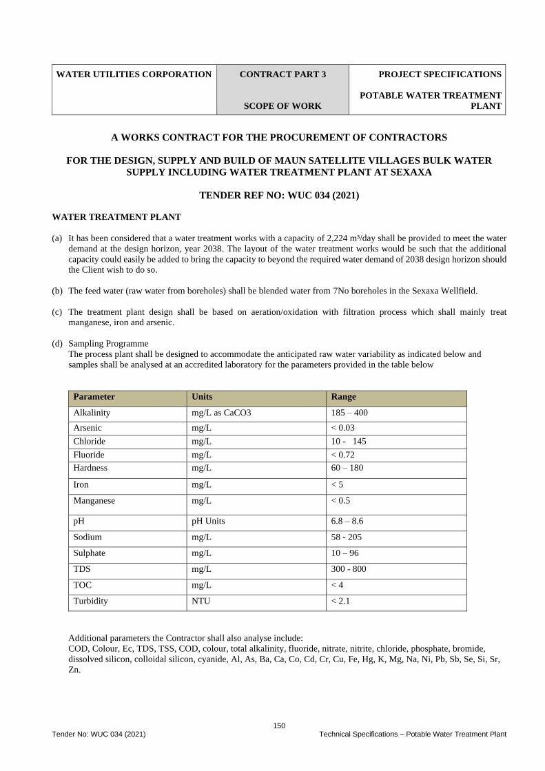
150 Tender No: WUC 034 (2021) Technical Specifications – Potable Water Treatment Plant
WATER UTILITIES CORPORATION
CONTRACT PART 3
SCOPE OF WORK
PROJECT SPECIFICATIONS
POTABLE WATER TREATMENT
PLANT
A WORKS CONTRACT FOR THE PROCUREMENT OF CONTRACTORS
FOR THE DESIGN, SUPPLY AND BUILD OF MAUN SATELLITE VILLAGES BULK WATER
SUPPLY INCLUDING WATER TREATMENT PLANT AT SEXAXA
TENDER REF NO: WUC 034 (2021)
WATER TREATMENT PLANT
(a) It has been considered that a water treatment works with a capacity of 2,224 m³/day shall be provided to meet the water
demand at the design horizon, year 2038. The layout of the water treatment works would be such that the additional
capacity could easily be added to bring the capacity to beyond the required water demand of 2038 design horizon should
the Client wish to do so.
(b) The feed water (raw water from boreholes) shall be blended water from 7No boreholes in the Sexaxa Wellfield.
(c) The treatment plant design shall be based on aeration/oxidation with filtration process which shall mainly treat
manganese, iron and arsenic.
(d) Sampling Programme
The process plant shall be designed to accommodate the anticipated raw water variability as indicated below and
samples shall be analysed at an accredited laboratory for the parameters provided in the table below
Parameter Units Range
Alkalinity mg/L as CaCO3 185 – 400
Arsenic mg/L < 0.03
Chloride mg/L 10 - 145
Fluoride mg/L < 0.72
Hardness mg/L 60 – 180
Iron mg/L < 5
Manganese mg/L < 0.5
pH pH Units 6.8 – 8.6
Sodium mg/L 58 - 205
Sulphate mg/L 10 – 96
TDS mg/L 300 - 800
TOC mg/L < 4
Turbidity NTU < 2.1
Additional parameters the Contractor shall also analyse include:
COD, Colour, Ec, TDS, TSS, COD, colour, total alkalinity, fluoride, nitrate, nitrite, chloride, phosphate, bromide,
dissolved silicon, colloidal silicon, cyanide, Al, As, Ba, Ca, Co, Cd, Cr, Cu, Fe, Hg, K, Mg, Na, Ni, Pb, Sb, Se, Si, Sr,
Zn.
151 Tender No: WUC 034 (2021) Technical Specifications – Potable Water Treatment Plant
(e) The treatment plant shall have a recovery rate of not less than 85%
(f) The treatment plant process shall be capable of recirculating a percentage of backwash water subject to quality tests (see
water treatment plant schematic diagram)
(g) Disinfectant shall be chlorine dioxide
(h) The treatment plant shall be flexible to allow for expansion in the future beyond the current design period.
(i) Other specifications are as provided under section C3.2.3.6.2
(j) Treatment plant operation manual shall be provided in the format agreed with the Engineer.
Standard of Workmanship
Workmanship shall be to the highest standard and all work shall be carried out by personnel qualified in the appropriate trade.
Particular attention shall be given to neatness, alignment and clear identification of all mechanical fitting and electrical cable
work to the treatment plant.
Operation of the Water Treatment Plant
The contractor shall operate the water treatment plant for 6months after completion. Operation shall include full time
personnel based at site for the 6months duration and during this time the Contractor shall work with staff seconded from the
user Client to allow for skill transfer in the operation of the plant
Training
a. It is the intention that staff from the Employer’s organization will gain familiarity with the equipment supplied under
the Contract during the Contract Period. Accordingly, the Tenderer will provide all reasonable access to nominated
staff, without additional cost, during the manufacture, installation and commissioning phases of the Contract.
b. The Tenderer shall provide operation and maintenance training courses for the complete system after equipment
installation and delivery of the O & M Manuals, but before handover. Prior to running these courses, the Tenderer
shall submit to the Engineer, for approval, course programmes giving details of the topics to be covered, the training
targets and the means by which it can be confirmed that the targets have been met.
c. Training for the operators shall include all the controls, displays and facilities available to them and shall cover the
operational aspects of the O&M Manuals.
d. Training for the maintenance technicians shall include a first line maintenance capability whereby any malfunctions
can be traced to a module or component, which can be replaced from the spares inventory.

152 Tender No: WUC 034 (2021) Technical Specifications – Telemetry and SCADA
WATER UTILITIES CORPORATION
CONTRACT PART 3
SCOPE OF WORK
PROJECT SPECIFICATIONS
SPECIFICATION FOR
TELEMETRY AND SCADA
SYSTEM
A WORKS CONTRACT FOR THE PROCUREMENT OF CONTRACTORS
FOR THE DESIGN, SUPPLY AND BUILD OF MAUN SATELLITE VILLAGES BULK WATER
SUPPLY INCLUDING WATER TREATMENT PLANT AT SEXAXA
TENDER REF NO: WUC 034 (2021)
Tenderer shall submit a Preliminary Design document where the overall system configuration is defined, general project
framework presented and schematics shall be provided. Following approval by the Engineer and Employer of the Preliminary
Design, the Tenderer shall submit a Detailed Design Document which will contain specifications and PID drawings. The
Tenderer shall submit a Functional Design Specification (FDS) document for approval by the
Engineer and Employer. The document shall specify in detail how the Tenderer’s equipment configuration and software
conform to the Specification and shall include the following:
• Technical specifications for all equipment (hardware and software) supplied, including:
➢ Manufacturer’s model numbers
➢ Performance specifications
➢ Environmental specifications
➢ Power consumption
➢ Dimensions
➢ SCADA application software and licenses to be purchased
➢ Standard software packages
➢ Equipment specific software packages
• Detailed functions specifications for equipment at all sites including:
Control Centres:
➢ Plant monitoring and control facilities
➢ Formats of display pages
➢ Operator keyboard facilities
➢ Command functions
➢ Alarm handling procedures
➢ System housekeeping
➢ Power up/down procedures
➢ Data storage and retrieval
➢ System security
➢ Reconfiguring of facilities
153 Tender No: WUC 034 (2021) Technical Specifications – Telemetry and SCADA
Remote sites:
Local display and control facilities
➢ Configuration and I/O capacity
➢ Use of portable field equipment
➢ Reconfiguring of facilities
• Outline installation drawings for the complete system including:
➢ System configuration schematic drawings
➢ Field cable termination schedule for each site
➢ Outline mechanical assembly drawings for each item of equipment showing leading dimensions, mounting
details, etc.
➢ Outline installation details and loop diagrams for instrumentation devices
➢ Outline installation drawings for radio communications equipment and antennae
➢ Outline installation drawings for power supplies, AC and DC, for the sites
➢ Bill of Quantities of the hardware and software.
FAT
During the manufacturing stage, the Tenderer shall submit a Factory Acceptance Test (FAT) specification for approval by
the Engineer. The FAT shall define the procedures for testing the complete system, fully configured and connected, at the
Tenderer’s premises before shipment to site. The Engineer and the Employer shall witness these tests.
The FAT shall demonstrate that the system conforms to the functional, performance and environmental specifications of the
FDS and shall include the following:
• Exhaustive functional tests of the operator interface for:
➢ Plant monitoring and control
➢ Verification of alarm handling procedures
➢ The above shall include the test of command signals as stated in the FDS.
• Functional tests to verify signal scan rates and response times to commands.
• Functional tests for power up/power down, data storage and retrieval parameter control, system security, system
housekeeping.
• Power supply tests including simulation of short-term breaks and operation at the limits of voltage and frequency
specified.
• Performance tests to demonstrate the autonomous nature of individual items of equipment under failure scenarios
and automatic recovery from failure. These tests shall include failure of Control Centre equipment, Remote sites
and the Communications systems.
• The system shall be assembled in the Tenderer’s works as a complete working system. Field signals shall be
simulated.
• The Tenderer shall carry out all necessary preliminary tests to correct any faults on the system prior to witnessed
testing. The Engineer shall sign off each test as it is successfully competed in the FAT document and also enter any
observations as necessary.
• All faults shall be corrected before the equipment is shipped to site. Major faults shall be re-tested and witnessed at
the Tenderer’s works.
154 Tender No: WUC 034 (2021) Technical Specifications – Telemetry and SCADA
SAT
Prior to installation works on site, the Tenderer shall submit a Site Acceptance Test (SAT) document for approval by the
Engineer. The SAT shall define procedures for acceptance testing of the complete system after installation and
commissioning at site.
The Engineer and Employer shall witness these tests.
The scope and content of the SAT shall follow procedures defined and approved in the FAT as closely as possible. Where
phased installations requiring temporary equipment configurations are necessary, procedures for testing these shall be
defined.
Installation and commissioning at site shall be inspected and witnessed by the Engineer.
The Tenderer shall submit test certificates for each stage of the commissioning programme.
The Site Acceptance Tests shall include but not be limited to:
• Exhaustive testing of every operator facility listed in the approved SAT document;
• Calibration and testing of signals from every item of instrumentation and plant to the remote sites
• Comprehensive testing of the complete LAN and communications network
• Verification of every signal, command, display and printout listed in the SAT document from live plant signals:
Once the SAT has been successfully completed with all faults corrected and with all supporting documentation submitted
and approved, the Tenderer shall issue a handover certificate for approval by the Engineer.
Testing Costs
The Factory Acceptance Tests and Site Acceptance Tests are designed to demonstrate that the system is fully compliant with
the approved Functional Design Specification.
The costs of this testing, including:
• Correction of all observed faults and subsequent re-testing
• Any other testing during the project that may be requested by the Engineer, to verify compliance with the Functional
Design Specification, shall be deemed to be included in the Contract Price.
Equipment Design Requirements
All the equipment offered shall be designed to conform to the best current engineering practices and shall be well proven for
the class of application described in this specification. The equipment shall be new, of sound workmanship and robust design,
and of a grade and quality suitable for the purpose intended and for the climatic conditions at the indicated sites.
All modules shall be identified by a reference number, which corresponds to that shown on the system drawings and the
O&M manuals. Modules, which are readily removable and interchangeable, shall also have identification markings on the
mountings plate or similar permanent item. Alternatively, a chart showing the location of removable and interchangeable
components shall be permanently fixed to the inside cover or side of the enclosure providing it is easily readable.
Future maintenance of equipment by others shall be borne in mind during design, manufacture and site installation. To this
end it is essential that all work is constructed strictly to consistent standards and individual variations of manufacture and
installation are eliminated. All components shall be installed in modules so that they are easily accessible for replacement
purposes and terminals are also easily accessible for field cabling. Where assemblies are mounted in enclosures the assembly
shall be easily replaceable and accessible.
For ease of maintenance and stocking of spares it is essential that the minimum number of different components of a similar
type shall be used. All identical components or modules shall be fully interchangeable.

155 Tender No: WUC 034 (2021) Technical Specifications – Telemetry and SCADA
Engineer’s and Tenderer's Drawings
The Engineer’s drawings issued with this Specification are intended only to show the basic principles on which this Contract
is to be prepared. These show typical layouts of how the various items of plant and equipment are related to each other. The
Tenderer shall provide manufacturer’s certified drawings and his own working drawings as defined below.
The drawings issued with this Specification are not to be taken or regarded as working drawings.
Should anything be omitted from the Engineer’s drawings or this Specification, which is usually considered necessary for
the completion of the Works, the Tenderer shall identify the omission.
Any requirement called for or implied in the Specification shall not be revoked or reduced due to the approval by the Engineer
of drawings. Such approval by the Engineer shall in no way relieve the Tenderer of his liability for providing and installing
everything necessary for the satisfactory completion of the Works in accordance with the Specification.
The Engineer’s approval of certified and/or working drawings shall not relieve the Tenderer of his responsibility for errors,
as the Engineer’s approval is only general; and is not intended to serve as a check. The Tenderer shall be fully responsible
for ensuring that the Works are properly completed and operate in accordance with the Specification and to the Engineer’s
satisfaction.
The cost of supplying these drawings and carrying out any alterations required to meet the requirements of the Specification
shall be included in the rates in the Schedule of Prices.
The standard of drawings shall be such as to be clearly legible when reduced to A4 size. All original drawings shall be A3
size.
Drawings for the O&M manuals shall be A4 or foldout A3 size to suit an A4 format document.
The Tenderer shall supply four hard copies and one soft copy (on CD or DVD) of final drawings and documents in accordance
with the following:
• Equipment assembly and installation drawings showing clearly the location, layout, labelling, fixing arrangements,
configuration and gland plate details of the equipment at each site.
• Circuit diagrams and instrument loop diagrams showing in schematic form all wiring between sensors/transducers,
radio communications equipment, Local Area Network, PLC’s, SCADA computers and general electrical equipment
and all other wiring together with all other circuitry to which this equipment is interconnected at each site.
• Drawings showing the geographical location of every site with radio paths.
Operation and Maintenance Manuals shall be supplied bound in hard covers and marked on the spine and cover with “Water
Utilities Corporation: Plant and Design-Build Contract for Maun Satellite Villages Connections including Water Treatment
Plant at Sexaxa “plus volume, copy number and title. These manuals shall be based upon the approved Function Design
Specification and shall include:
• Overall description of the complete Telemetry & SCADA system, as installed and commissioned, with specific
descriptions of equipment at each site and how individual items of equipment operate together as a system.
• Complete operational instructions for all equipment supplied at the Control Centres, including keyboard/mouse
operations, LED monitors’ page formats, printed log formats, etc.
• Manufacturers’ full technical and environmental data for each individual item of equipment included in the delivery.
• Manufacturer’s service manuals for each individual item of equipment including circuit diagrams, component list
etc.
• Complete operational and maintenance instructions for every item of equipment supplied at each site, including
default settings, part list, etc.
156 Tender No: WUC 034 (2021) Technical Specifications – Telemetry and SCADA
• Complete operational and maintenance instructions for the radio communications system, including all items of
radio equipment.
• Complete operational and maintenance instructions for the Local Area Network.
• Recommended spares list for the complete system.
• Compete software code listings, documentation and configuration schedules including sufficient information for
modification to be readily carried out to the Central Station, Data Processing and outstanding software.
• Full description of hardware and software fault finding and diagnostic procedures.
Earthing and Lightning Protection
Steps shall be taken to ensure that the Control Centres and all remote sites’ equipment are fully protected against the effects
of lightning strikes and mains supply surges. Specifically, protection shall be applied to the incoming mains power supply,
the input and output signal lines and from sensors, transducers, radio communications, antennae and signal feeders. Earthing
and Lightning protection systems shall be in accordance with:
• SABS 0313 Protection against lightning
• BS 7430 Earthing
All surge suppression equipment shall be self-contained and self-resetting. The suppression equipment shall be selected so
that the let-through voltage specification does not exceed the absolute maximum voltage specified for the particular
equipment being protected.
Signals lines from external sensors shall have suppressors fitted at both ends of each line and shall be installed and connected
in accordance with the manufacturer’s recommendations.
Site Power Supplies
At locations where mains power supplies are provided, equipment shall operate from single-phase AC supplies at a normal
230V. 50Hz.
At certain Outstation sites, mains supply quality can be variable and subject to frequent short-term interruptions. For these
sites, Outstations, which can also operate from battery supported DC supplies, are preferred.
At the Control Centre, SCADA computers, printers, LAN, telemetry and communications equipment shall operate from
Uninterruptible Power Supply (UPS) equipment. The UPS shall provide a supply at a normal 230V 50 Hz, using a rectifier,
battery and inverter configuration. The UPS shall provide a maintained single-phase supply for the Control Centre equipment.
It shall be rated to provide 30% spare capacity above the maximum equipment load.
The UPS shall have the main following units:
• Battery charger with trickle and boost charging facilities that operate in accordance with the battery manufacturer’s
recommendations for the charging of sealed type batteries.
• A mains monitoring unit together with a system test pushbutton for simulating AC mains failure.
• AC and DC isolators
• AC Bypass Switch.
Batteries shall be of the acid type with the cell containers designed to withstand shock and vibration. Batteries shall be
installed complete with all connections made and mounted on a purposed built cradle. If batteries are mounted in the same
cubicle as the electronic equipment, they shall be installed in a sealed separately vented enclosure.
The battery charging equipment shall be of the solid state automatic constant voltage type suitable for operation on a single-
phase supply capable of float charging on the system under the conditions specified. The high rate charging circuit shall be
adequate for recharging the batteries from 75% discharged to fully charged state in seven hours.

157 Tender No: WUC 034 (2021) Technical Specifications – Telemetry and SCADA
The charging equipment shall be complete with a manual changeover switch for charging rates, indication of charging and
discharge currents and voltages, together with charge fail and earth leakage alarms. Current limit protection shall be provided
to prevent damage to the charger and battery.
The UPS equipment shall be suitable for unattended operation and shall be continuously rated to supply fully rated load
within the steady state and transient performance limits. These limits shall not be exceeded with the full rated load is supplied
from the battery throughout the minimum discharge period.
Surge diverters shall be fitted to protect the equipment against system disturbances, including those due to switching faults,
and lightning strikes. Surge diverters shall comply with BS 2914.
Noise emission from the equipment shall not exceed a sound pressure level of 55 dBA measured one metre from any surface
of the enclosure.
The equipment shall incorporate radio interference suppression complying with BS 800.
The enclosure shall be IP55 rated, of rigid steel construction, free standing and floor mounted.
Enclosure shall be ventilated and vermin proofed.
The enclosure shall provide easy access to all components for inspection, maintenance and replacement. Access doors shall
be on the front of the enclosure and shall be lockable.
Transformers shall be dry type, BS 171 Cooling Class AN.
Fuses shall be HRC type complying with BS 88 parts 1 and 2, fusing factor Class Q1. High-speed fuses for semiconductor
protection shall comply with BS 88 Part 4. One spare fuse of each rating shall be provided and clipped inside the cubicle.
Power semiconductors shall be silicon and be protected against overvoltage and overcurrent.
Low power logic and control circuits shall be constructed on plug-in printed circuit cards. Mechanical interlocks shall provide
to prevent incorrect insertion of printed circuit cards.
All relays shall be of the plug-in type and shall be supplied with dust cover.
158 Tender No: WUC 034 (2021) Site Information
WATER UTILITIES CORPORATION
CONTRACT PART 4
SITE INFORMATION
SITE INFORMATION
A WORKS CONTRACT FOR THE PROCUREMENT OF CONTRACTORS
FOR THE DESIGN, SUPPLY AND BUILD OF MAUN SATELLITE VILLAGES BULK WATER
SUPPLY INCLUDING WATER TREATMENT PLANT AT SEXAXA
TENDER REF NO: WUC 034 (2021)
Part 4: Site Information
1.1. Project Area
The project is undertaken in the Satellite Villages of Sexaxa, Matsaudi, Sakapane and Shorobe just outside the Maun water
distribution network. These villages have a combined population of 2152 as of 2011 population census. Maun is located
900km North West of Gaborone and 550km West of Francistown. The village is on the South-Eastern edge of the Okavango
delta and is split from East to West by the Thamalakane River. The Satellite Villages of Sexaxa, Matsaudi, Sakapane and
Shorobe are situated just to the north of Maun.
1.2. Location
The Satellite villages connections including treatment plant at Sexaxa, covers an approximate combined 30km length of
borehole collector and transmission pipelines from water treatment plant to the villages of Sexaxa, Matsaudi, Sakapane and
Shorobe. Each of these villages is to the east of Thamalakane River and lie on a gentle undulating terrain sloping towards the
river, just to the north of Maun build-up and water supply area. The topography of the satellite villages can be described
according to the land systems as depicted on the Land Systems Map of the Republic of Botswana. Approximately 60% of
the area belongs to the Alluvial System, whereas the remaining 40% is Sandveld.
1.3. Weather
The highest mean monthly maximum temperatures are generally recorded in January and range between 32°C and 35°C.
Lowest mean monthly minimum temperatures are recorded in July and range from 1°C to 5°C. In association with the passage
of cold fronts, sub-zero temperatures may occasionally be recorded during the winter season.
Rainfall is of the order of 540 mm per year and the amounts are variable. Some months can experience no rainfall. The period
May to September is almost completely dry. The total rainfall is usually concentrated in a small number of intense storms
generally of short duration.
1.4. Geology
The Satellite villages connections including treatment plant at Sexaxa is predominantly Kalahari Sands overlying Calcretes
which in turn overly Hardpan Calcretes and, at greater depths, Silcretes. The thickness of the Kalahari Sand varies from 0.5m
to over 6m but is generally about 2m thick throughout the project area. The underlying Calcretes vary from finely grained
Calcrete to hard Nodular Calcrete suitable for road construction, generally lying in 1m to 3m thick layers. Hardpan Calcretes
and Silcrete are generally found at depths of more than 6m.
The study area has generally similar soil material and possess comparable depths and stretches of the Kalahari sands covering
the area offshore. On shore soils are of clayey and sandy material deposits annually compiled by the flowing river. The soils
nearer the swamps and river have high quantities of fines because of seasonal accumulation of flood waters over them.
1.5. Existing site services
The Contractor shall be responsible for establishing the location, protection and undertaking necessary temporary diversion
of existing site services. He shall make dimensioned sketch describing any exposed service and locating it in plan and section
relative to permanent reference points. Date and sign the sketch and submit it to the Engineer. Any service so exposed shall
not be covered up by permanent works until sketches have been submitted.
159 Tender No: WUC 034 (2021) Site Information
1.6. Water sources
The Contractor shall be responsible for availability of construction water on site at his own cost and ensuring that the water
availed is also suitable for human consumption and it meets the specifications, BOS 32: 2009 Drinking water specification
1.7. Visitors
A visitors Safety Induction Program will be established explaining the site, the conditions applicable to their entry onto site
and the necessary PPE they will be required to wear.
1.8. Servitude (Rights of Way)
• Routing approvals
• Land acquisition
• Land surveys
1.9. Additional field investigation
The Contractor will be responsible for any additional field investigation to locate existing pipelines (services) more accurately
where the location is critical, such as along live water mains, BPC, BTC or Bofinet underground networks, the contractor is
to assess the filed investigation information and dig trial pits as necessary to ascertain and confirm any existing services.
1.10. Demolition of existing Structures
The Contractor shall be responsible for dismantling, removal of the existing structures which might be deemed to interfere
with his work to enable the construction of new works. The cost for these works shall be deemed to have been included in
the cost.
1.11. Possible Project Risks
The Contractor shall be responsible for identification of possible project risks during tender and possible mitigation measures.
Several categories of Project risk anticipated (provided as guidance only) include:
• Health, Safety Risk;
• Programme Risk;
The risks are not exhaustive and the contractor shall come up with other risks. Such risks shall be deemed to have been
considered during tender and are included in the tender price.
![Minor Works Contract - Pan Pac Forest Products Ltd Works Contract... · 2020-01-20 · 1 Minor Works Contract Contract Agreement [Short title for Contract] [add Contract Reference](https://img.pdfslide.us/doc/110x75/5e740b224b2c464b4724fa7f/minor-works-contract-pan-pac-forest-products-ltd-works-contract-2020-01-20.jpg)