Embed Size (px)
Citation preview
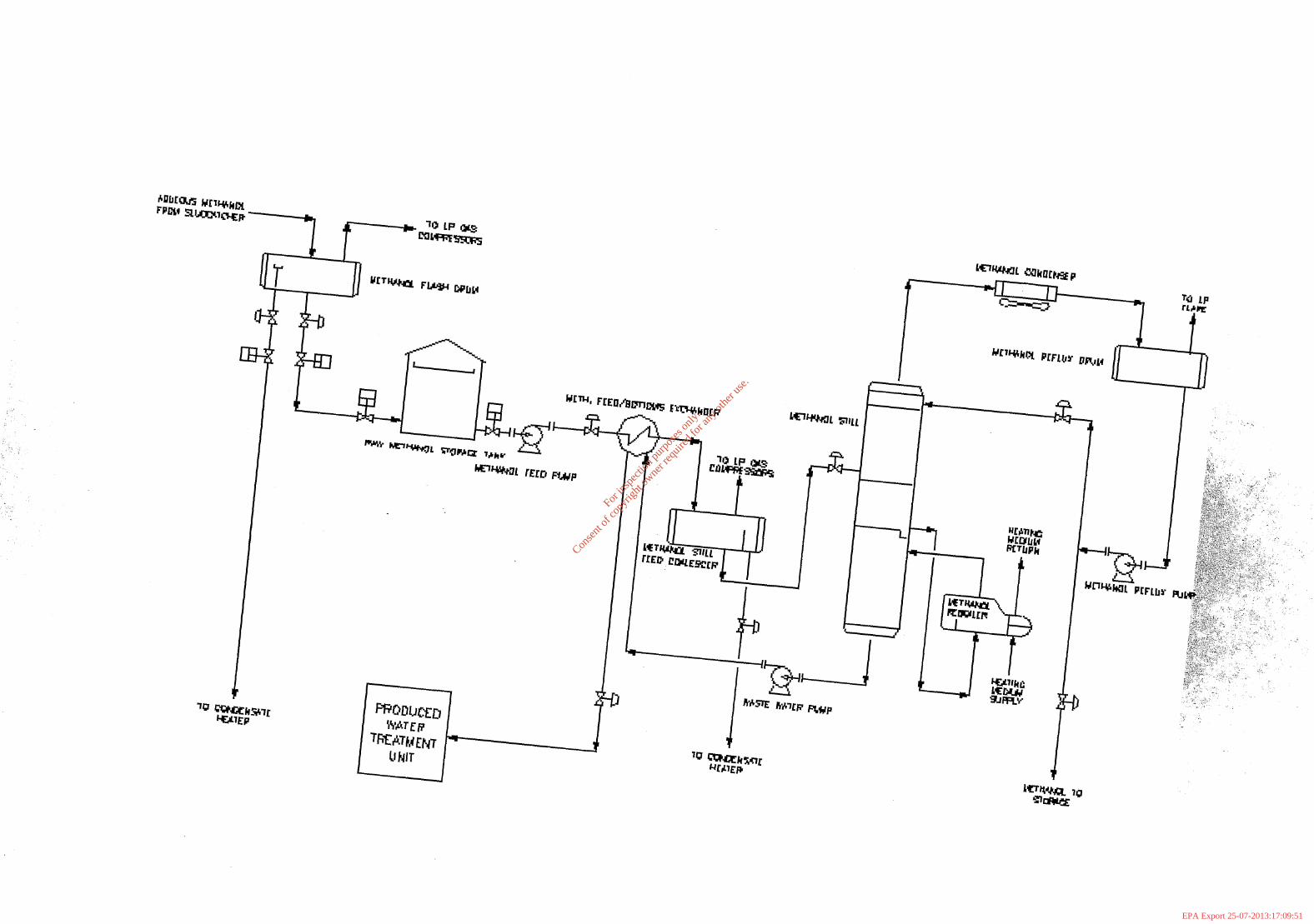
Water Treatment Unit -
For
insp
ectio
n pur
pose
s only
.
Conse
nt of
copy
right
owne
r req
uired
for a
ny ot
her u
se.
EPA Export 25-07-2013:17:09:51
For
insp
ectio
n pur
pose
s only
.
Conse
nt of
copy
right
owne
r req
uired
for a
ny ot
her u
se.
EPA Export 25-07-2013:17:09:51
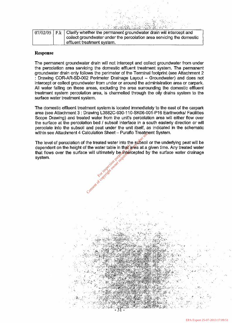
collect groundwater under the percolation area servicing the domestic effluent treatment system.
Response
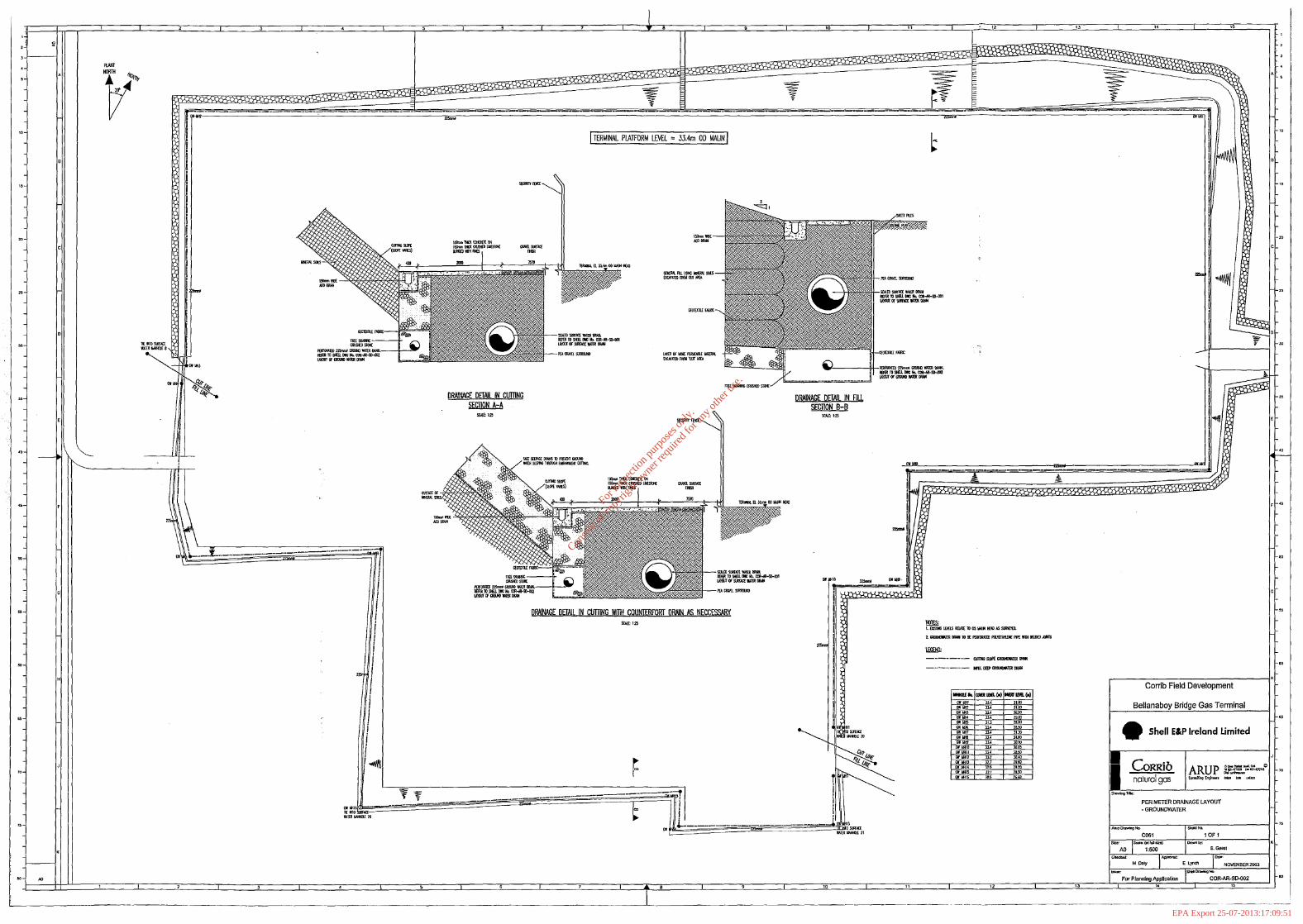
The permanent groundwater drain will not intercept and collect groundwater from under the percolation area servicing the domestic effluent treatment system. The permanent groundwater drain only follows the perimeter of the Terminal footprint (see Attachment 2 : Drawing COR-AR-SD-002 Perimeter Drainage Layout - Groundwater) and does not intercept or collect groundwater from under or around the administration area or carpark. All water falling on these areas, excluding the area surrounding the domestic effluent treatment system percolation area, is channelled through the oily drains system to the surface water treatment system.
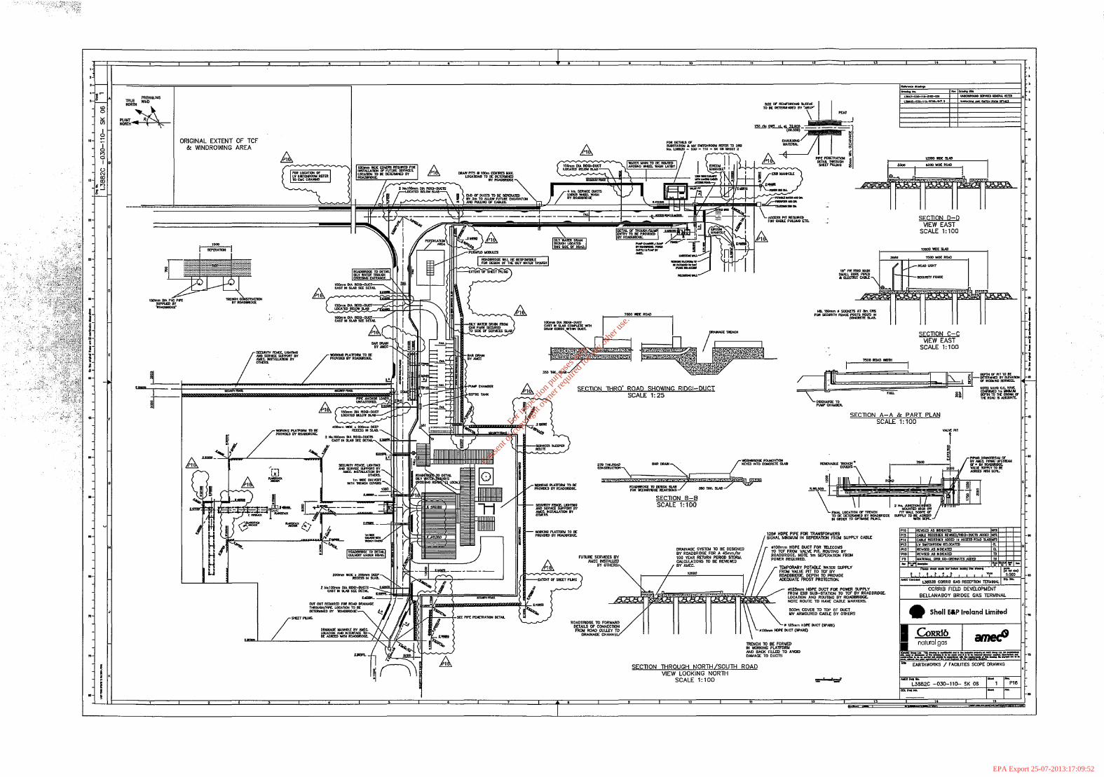
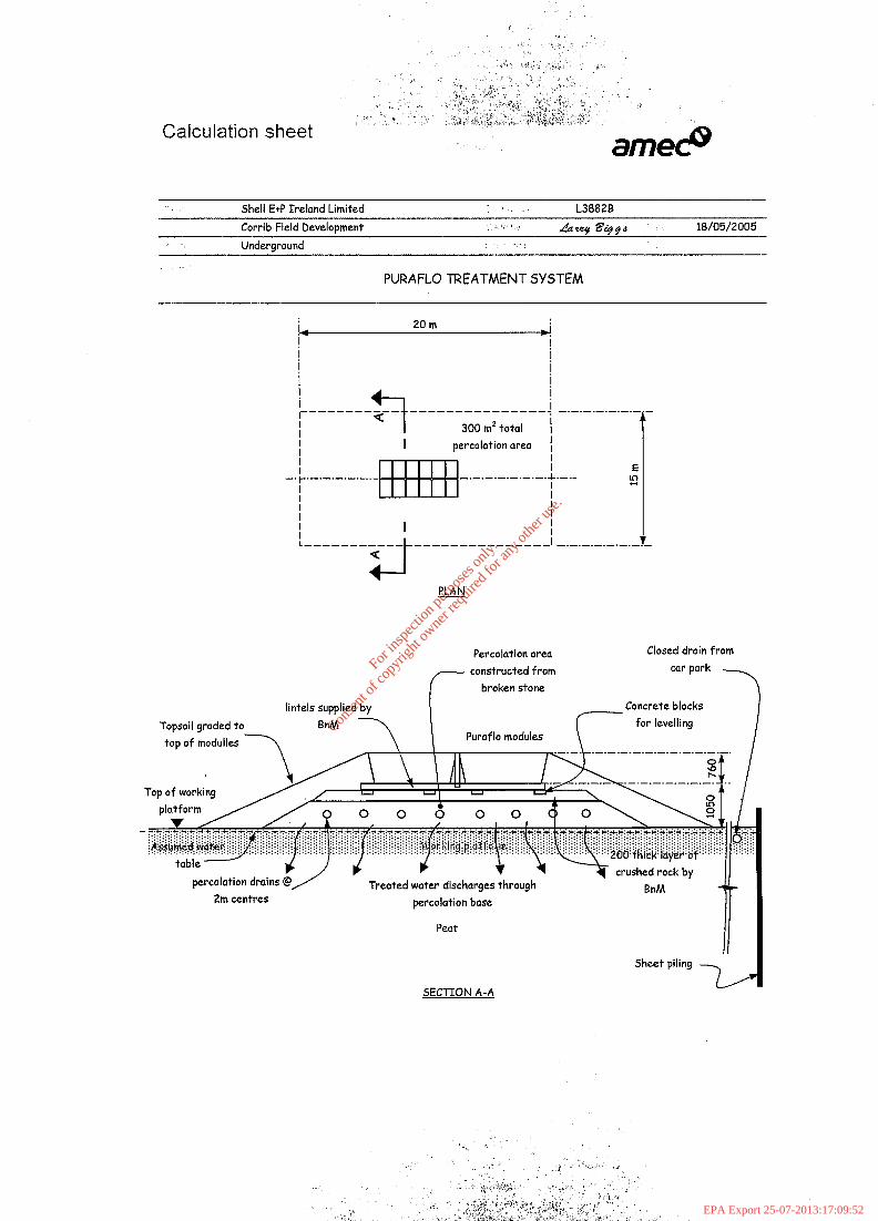
The domestic effluent treatment system is located immediately to the east of the carpark area (see Attachment 3 : Drawing L3882C-030-I IO-SKO6-001 -PI 6 Earthworks/ Facilities Scope Drawing) and treated water from the units percolation area will either flow over the surface at the percolation bed / subsoil interface in a south easterly direction or will percolate into the subsoil and peat under the unit itself, as indicated in the schematic within see Attachment 4 Calculation Sheet - Puraflo Treatment System.
The level of percolation of the treated water into the subsoil or the underlying peat will be dependent on the height of the water table in that area at a given time. Any treated water that flows over the surface will ultimately be intercepted by the surface water drainage system.
For
insp
ectio
n pur
pose
s only
.
Conse
nt of
copy
right
owne
r req
uired
for a
ny ot
her u
se.
EPA Export 25-07-2013:17:09:51
.‘: ,_, (_ ‘- , .
.i
I : ‘t. I *
I , .
, . , “ . . , ~ ; : , :
~’ : . , : , , :
I’, . , t . , ._ ‘..~. ,.I ’:,,, .’
Attachment 2 : COR-AR-SD-002 Perime&Dra&ge L$out?&ound&ater
Attachment 3 : Drawing L3882C-030-I 1 O-SK06-OOI-PI 6 Earthworks/ Facilities Scope Drawing
Attachment 4 Calculation Sheet - Puraflo Treatment System (Excel Worksheet)
For
insp
ectio
n pur
pose
s only
.
Conse
nt of
copy
right
owne
r req
uired
for a
ny ot
her u
se.
EPA Export 25-07-2013:17:09:51
‘, . . .<...‘..!. .’
: .
” * t , : , . ,‘\‘,V
: . - ; . , i. I’ ‘(
.~ : .
Attachment 2 : COR-AR-SD-002 Perimeter Draiia& byout - Groundwater
For
insp
ectio
n pur
pose
s only
.
Conse
nt of
copy
right
owne
r req
uired
for a
ny ot
her u
se.
EPA Export 25-07-2013:17:09:51
For
insp
ectio
n pur
pose
s only
.
Conse
nt of
copy
right
owne
r req
uired
for a
ny ot
her u
se.
EPA Export 25-07-2013:17:09:51
,‘- _. ‘,
;I
-, ,.I
,a.* /.(’ : _/
‘.,. ,’ i :,,. ‘i Attachment 3 : Drawing L3882C-030-l lO~SK06-0~~~h16 gar%wt%ks? Facilities Scope Drawing
For
insp
ectio
n pur
pose
s only
.
Conse
nt of
copy
right
owne
r req
uired
for a
ny ot
her u
se.
EPA Export 25-07-2013:17:09:51
For
insp
ectio
n pur
pose
s only
.
Conse
nt of
copy
right
owne
r req
uired
for a
ny ot
her u
se.
EPA Export 25-07-2013:17:09:52
-,a -, -.. .,
Attachment 4 Calculation Sheet - Fbraflo Treatment System (Excel Worksheet)
For
insp
ectio
n pur
pose
s only
.
Conse
nt of
copy
right
owne
r req
uired
for a
ny ot
her u
se.
EPA Export 25-07-2013:17:09:52
Calculation sheet
Shell E+P Ireland Limited i, .a L3882B
Corrib Field Development ,: ‘, * JaCarat t?c+d 18/05/2005
Underground ,_.
PURAFLO TREATMENT SYSTEM
I, 20 m
I , !
I I I I I I I I I r-----
----- ---------------
l ‘t
I
K ; -.-.-.-.- .-.-
300 mz total I
I I percolation area 1
-+-.-.-.-.-.mi-.- .-.-.-.-.-. I.-.- g
I I I I I I t L----------- ---------------
+-J
I ___._.-.-.-.- -x
PLAN
Percolation area
constructed from
Closed drain from
Topsoil graded to Puraflo modules
Concrete blocks
.-.-.-.-.-.-.-.-.-.-
percolation base
Peat
SECTION A-A
For
insp
ectio
n pur
pose
s only
.
Conse
nt of
copy
right
owne
r req
uired
for a
ny ot
her u
se.
EPA Export 25-07-2013:17:09:52
07/02/05 F.1
: , .
: , s
I . ( ,
.’
I ; ” . _I “ - / ( ; : : -
: , , . \ ! , . . ‘ . ‘ I / . . . y
i,. _*~ . ; -
. ‘ , . . : “ , . , * ; A , ;~&t ! , . _ , ii-ii , ‘ ; - _i . . ; , , ) , , .‘, . . _y,
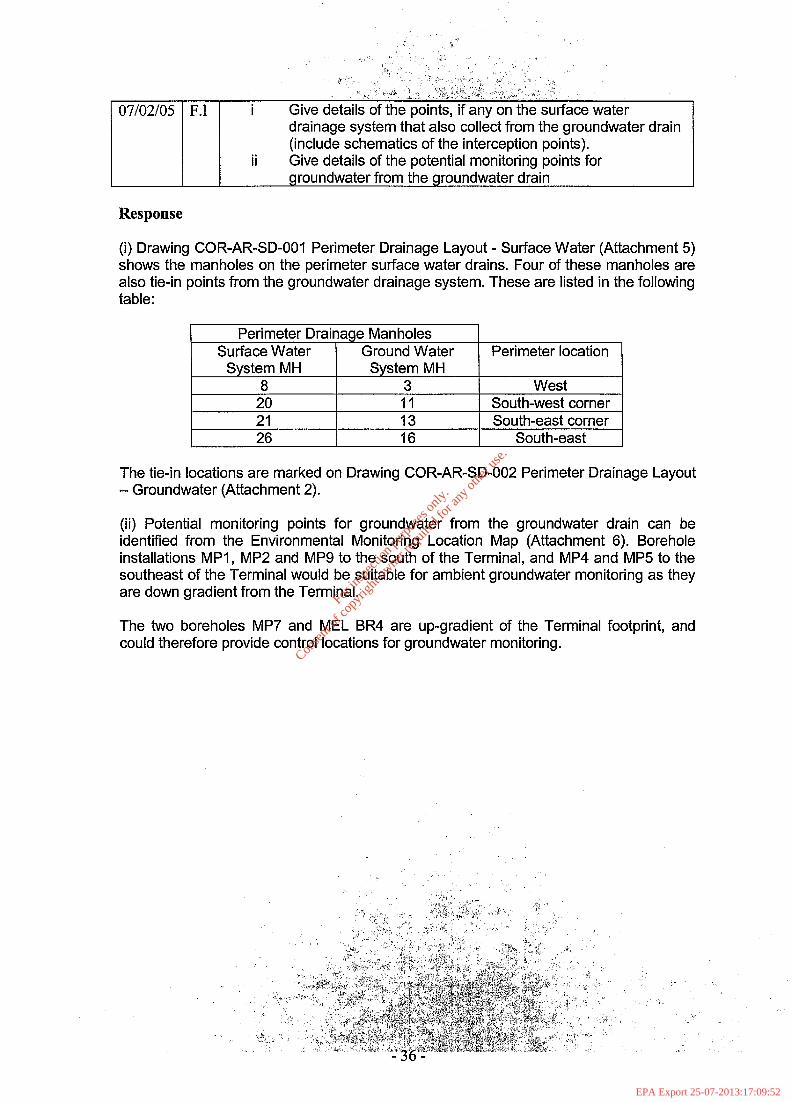
i Give details of the points, if any on the surface water drainage system that also collect from the groundwater drain (include schematics of the interception points).
ii Give details of the potential monitoring points for groundwater from the groundwater drain
Response
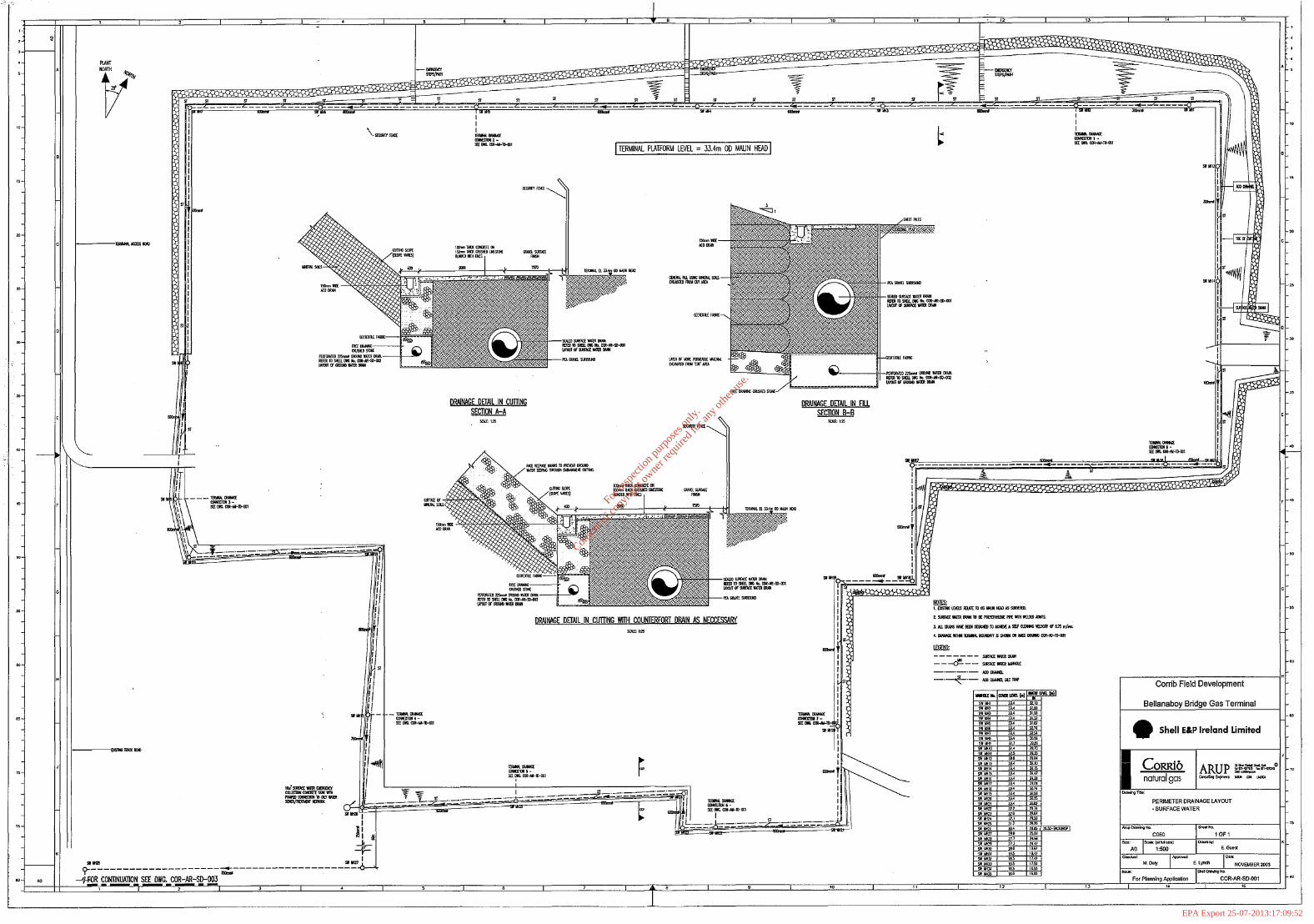
(i) Drawing COR-AR-SD-001 Perimeter Drainage Layout - Surface Water (Attachment 5) shows the manholes on the perimeter surface water drains. Four of these manholes are also tie-in points from the groundwater drainage system. These are listed in the following table:
Perimeter Drainage Manholes Surface Water Ground Water
System MH System MH 8 3
20 11 21 13 26 16
Perimeter location
West South-west corner South-east corner
South-east
The tie-in locations are marked on Drawing COR-AR-SD-002 Perimeter Drainage Layout - Groundwater (Attachment 2).
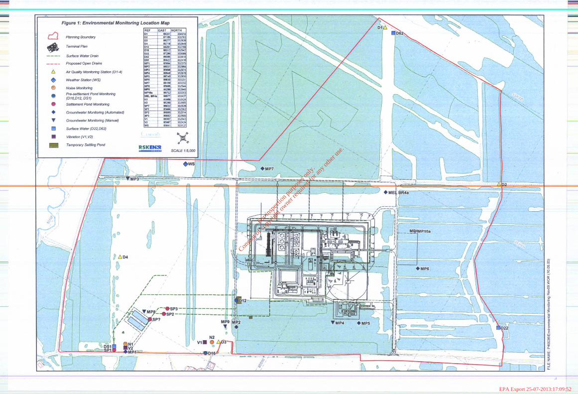
(ii) Potential monitoring points for groundwater from the groundwater drain can be identified from the Environmental Monitoring Location Map (Attachment 6). Borehole installations MPI, MP2 and MP9 to the south of the Terminal, and MP4 and MP5 to the southeast of the Terminal would be suitable for ambient groundwater monitoring as they are down gradient from the Terminal.
The two boreholes MP7 and MEL BR4 are up-gradient of the Terminal footprint, and could therefore provide control locations for groundwater monitoring.
For
insp
ectio
n pur
pose
s only
.
Conse
nt of
copy
right
owne
r req
uired
for a
ny ot
her u
se.
EPA Export 25-07-2013:17:09:52
c:
.‘,’ ., ̂ C,, -7,
,I i : i, -_ ; ‘.i-
Attachment 5 : COR-AR-SD-001 Perimeter b~a’kaQ’& L&y& - Z&Faie Water
Attachment 6 :.Environmental Monitoring Location Map
For
insp
ectio
n pur
pose
s only
.
Conse
nt of
copy
right
owne
r req
uired
for a
ny ot
her u
se.
EPA Export 25-07-2013:17:09:52
For
insp
ectio
n pur
pose
s only
.
Conse
nt of
copy
right
owne
r req
uired
for a
ny ot
her u
se.
EPA Export 25-07-2013:17:09:52
For
insp
ectio
n pur
pose
s only
.
Conse
nt of
copy
right
owne
r req
uired
for a
ny ot
her u
se.
EPA Export 25-07-2013:17:09:52
~. _/, .t.. ,“ :. ‘/ _~) .,,.. :‘. ‘,
‘:.;~ , ; 11,. IA :, i ‘.:3!.., ., I” z,‘,,;’ e.,;
Attachment 6 :.Environmental Monito&ig’~koc&i&“Map .*’ ,.d .
For
insp
ectio
n pur
pose
s only
.
Conse
nt of
copy
right
owne
r req
uired
for a
ny ot
her u
se.
EPA Export 25-07-2013:17:09:52
For
insp
ectio
n pur
pose
s only
.
Conse
nt of
copy
right
owne
r req
uired
for a
ny ot
her u
se.
EPA Export 25-07-2013:17:09:52
:.
. . . .’
:
..:jL -7 :: I’: *t: ,( , :. /, d+. : ; ,g: .,, <;
( .k, (. ‘.
‘:;;+.y ‘>- *.;,.:. : .J _
.:: <_ , e,l -21;; ,:;$&p ,“‘Z’ <. -*
07/02/05 F.m Give the total catcht-nent area for the uncontaminated storm water drainage system. Clarify if the uncontaminated surface water drainage system in a gravity flow system.
Response
The uncontaminated storm water drainage system collects rain water from the roads, all non paved areas and from the plot building roofs (excluding the compressor house roof and the administration building area roofs which drains to the open drains system,) within the Terminal footprint. The uncontaminated surface water drains to the perimeter piped (surface water) drainage system and discharges to the settlement ponds.
Uncontaminated rainwater that falls adjacent to the security fence drains directly into the perimeter drainage system and not into the Terminal drainage ditch system and therefore is not part of the storm water drainage system. Also, uncontaminated rain water that falls onto peat areas (e.g. the flare area) does not have a dedicated drainage system to drain into. This water will drain into the ground. These figures have not been taken into account in the total calculations below.
Storm Water Ditches = 65,477m2 Plot Building Roof = 6253m*
The total Uncontaminated Storm Water Drainage System = 71,73Om*
The total catchment area for the Terminal site is 136,l lOm* (total perimeter drainage system (includes storm water drainage system), total open drain system (includes drained bunded areas), undrained bunded areas (firewater pond) and peat areas).
The uncontaminated surface water drainage system is a gravity flow system. Attachment 5 (Drawing No. COR-AR-SD-001 Perimeter Drainage Layout - Surface Water) shows the flow direction arrows at various intervals along the footprint perimeter sealed/piped surface water drain. The drawing also provides details on the surface water manholes along the perimeter drain, as well as their associated invert levels. The gradual fall in a southwesterly direction in the invert levels for each of the manholes shows that the system is gravity fed.
The carrier pipe from the Terminal’s perimeter surface water drainage system falls from the invert level of the surface water manhole in the south west corner of the Terminal’s footprint (SW MH20 invert level at 30.25m AOD) to the settlement ponds which lie at around 18m AOD (invert level of pond of the northern settlement ponds is approximately 16m AOD). This fall takes place over a distance of approximately 200m.
For
insp
ectio
n pur
pose
s only
.
Conse
nt of
copy
right
owne
r req
uired
for a
ny ot
her u
se.
EPA Export 25-07-2013:17:09:52
\ EPA Wastewater Treatment Manuals. -
Response
The domestic effluent treatment system was assessed against the following Environmental Protection Agency Water Treatment:
l Environmental Protection Agency-Water Treatment Manuals - Filtration l Environmental Protection Agency - Water Treatment Manuals - Disinfection . Environmental protection Agency -Water Treatment Manuals - Coagulation,
Flocculation 81 Clarification
The onsite domestic effluent treatment system is the Bord na Mona PurafloTM Liquid Effluent Treatment System. The system consists of a filter system fitted to the outlet of a connected septic tank, an effluent collecting chamber (sump), a pump and a number of biofibrous media containing modules. The effluent from the septic tank is evenly distributed over the surface of the biofibrous media and percolates through the media before emerging as a treated liquid at the base of the unit. The treated effluent from the base of the unit can either pass into a prepared stone filled percolation area and into the ground or can be discharged via a stone filled drain to surface water drain or ditch. Taking the above operational description into account only the first Water Treatment Manual - Filtration - is applicable to the PurafloTM system and the latter two have been discounted as they are not applicable.
The system operates in a similar way to a slow sand filter where the effluent’s particles are removed by straining, adsorption, and microbiological action. The treatment of the waste is achieved by a combination of physical, chemical and biological interactions between the pollutants and the biofibrous media. Both mechanisms have graded gravel or broken stone underlying the filter media.
For
insp
ectio
n pur
pose
s only
.
Conse
nt of
copy
right
owne
r req
uired
for a
ny ot
her u
se.
EPA Export 25-07-2013:17:09:52
Y.>” ‘.I >
. - - , ; : _ __ , . .
- . i ) , i , : /
_‘. ‘#_.‘:,,~
‘,, ( . ?’ ! , ; r) . ‘. ..‘n ii . , ._ .
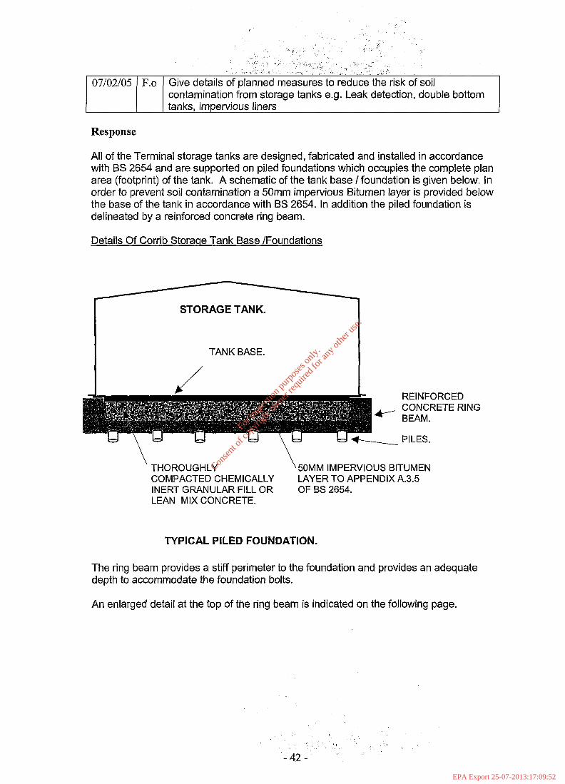
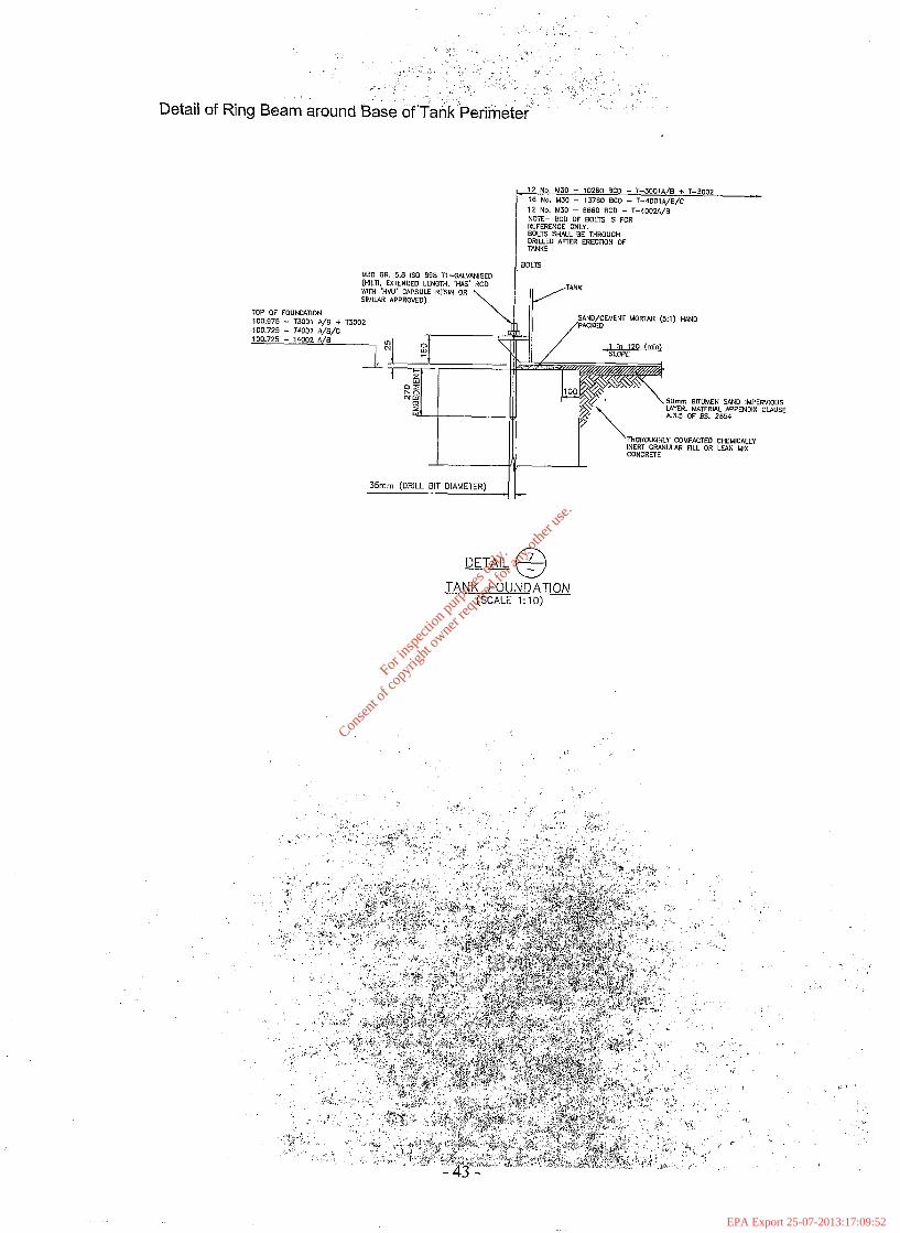
07/02/05 F.o Give details of planned measures to reduce the risk of soil contamination from storage tanks e.g. Leak detection, double bottom tanks, impervious liners
Response
All of the Terminal storage tanks are designed, fabricated and installed in accordance with BS 2654 and are supported on piled foundations which occupies the complete plan area (footprint) of the tank. A schematic of the tank base / foundation is given below. in order to prevent soil contamination a 50mm impervious Bitumen layer is provided below the base of the tank in accordance with BS 2654. In addition the piled foundation is delineated by a reinforced concrete ring beam.
Details Of Corrib Storaqe Tank Base /Foundations
I TANK BASE. I
REINFORCED CONCRETE RING
\ THOROUGHLY \ 50MM IMPERVIOUS BITUMEN COMPACTED CHEMICALLY LAYER TO APPENDIX A.3.5 INERT GRANULAR FILL OR OF BS 2654. LEAN MIX CONCRETE.
TYPICAL PILED FOUNDATION.
The ring beam provides a stiff perimeter to the foundation and provides an adequate depth to accommodate the foundation bolts.
An enlarged detail at the top of the ring beam is indicated on the following page.
For
insp
ectio
n pur
pose
s only
.
Conse
nt of
copy
right
owne
r req
uired
for a
ny ot
her u
se.
EPA Export 25-07-2013:17:09:52
! .._
; , i.
. , I
,;%‘.:. . , . , : z -_ \ , a.‘.._
3 : ‘.
__- ,’ i ,‘I ,j,
.i r , u; _, , : ; : . . ‘.‘
: . . . , ‘, : . . , -
Detail of Ring Beam around Base of TankPeri&& ‘. ’
Km GR. 5.8 IS0 898 T1-G.4L”~,SED (HILTI. EXTENDED LENGTH. ‘HAS’ ROD wmi ‘HVU’ CAPSULE RESIN OR SIMIIAR APPROVED)
TOP OF FOUNDATION
35mm (DRILL BIT DIAMETER)
12 No. M30 - 10260 BCD - T--JOOlA/B ,. T--3002 16 No. M30 - 13760 BCD - T-4001~,B,C 12 No. MO - 8660 BCD - T-40024/~ NOTE- SC0 DF BOLTS IS FOR REFERENCE ONLY. BOLE SHALL BE THROUGH DRlLLEO AFrER ERECTKIN OF TANKS
3OLTS
SAND/CEMENT MORTAR (5:l) HAND
TANK FOUNDATION (SCALE 1: 10)
For
insp
ectio
n pur
pose
s only
.
Conse
nt of
copy
right
owne
r req
uired
for a
ny ot
her u
se.
EPA Export 25-07-2013:17:09:52
Response
The European Waste Code (EWC) for the settlement pond sludge (peat debris) is 17 05 04 (soil and stones other than those mentioned in 17 05 03). It is unlikely that the settlement ponds will accumulate much sludge once the construction phase of the project has been completed. However, it is possible that some loose debris may be flushed from the cut drains into the settlement ponds, and a volume of 1 ,400m3 has been allowed for construction purposes.
It is expected that the settlement ponds will be cleaned after approximately 3 years. Thereafter pond maintenance is not expected to take place.
Addendum to Table H.1
l Waste Material = Settlement Pond Sludge (Peat Debris) l EWC Code = 17 05 04 l Main Source = loose peat debris in cut drains. l Quantity = -1 ,400m3 in initial 3 years. Nil thereafter. l On site recovery/disposal = Not applicable 0 Off site recovery, reuse or recycling = Licensed Waste Contractor to be decided l Off site disposal = Licensed Waste Contractor to be decided
For
insp
ectio
n pur
pose
s only
.
Conse
nt of
copy
right
owne
r req
uired
for a
ny ot
her u
se.
EPA Export 25-07-2013:17:09:52