Embed Size (px)
Citation preview
Water Tests of Hg System
V.B. Graves
P.T. Spampinato
Muon Collaboration Friday MeetingDec 8, 2006
2MC Friday Meeting 8 Dec 2006
OAK RIDGE NATIONAL LABORATORYU. S. DEPARTMENT OF ENERGY
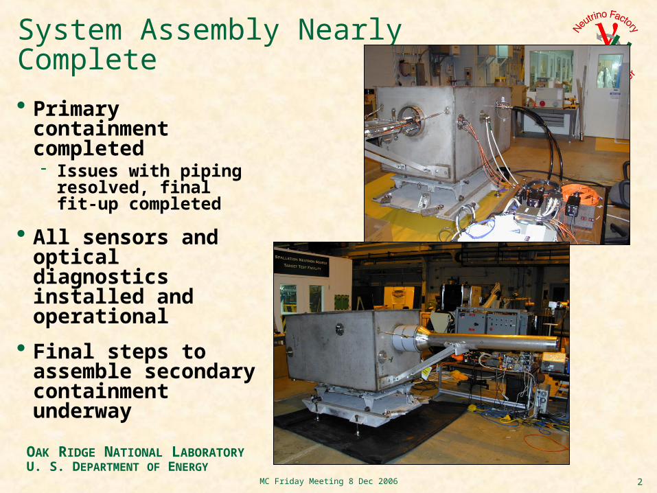
System Assembly Nearly Complete
Primary containment completed Issues with piping
resolved, final fit-up completed
All sensors and optical diagnostics installed and operational
Final steps to assemble secondary containment underway
3MC Friday Meeting 8 Dec 2006
OAK RIDGE NATIONAL LABORATORYU. S. DEPARTMENT OF ENERGY
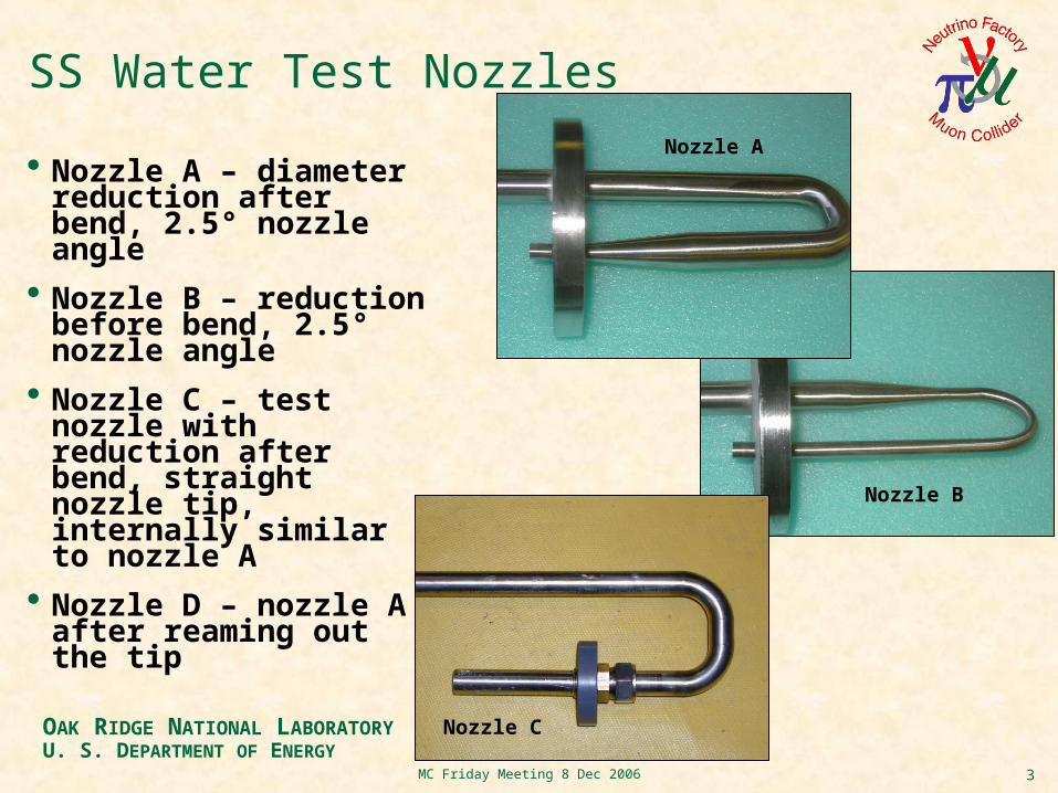
SS Water Test Nozzles
Nozzle A – diameter reduction after bend, 2.5° nozzle angle
Nozzle B – reduction before bend, 2.5° nozzle angle
Nozzle C – test nozzle with reduction after bend, straight nozzle tip, internally similar to nozzle A
Nozzle D – nozzle A after reaming out the tip
Nozzle B
Nozzle C
Nozzle A
4MC Friday Meeting 8 Dec 2006
OAK RIDGE NATIONAL LABORATORYU. S. DEPARTMENT OF ENERGY
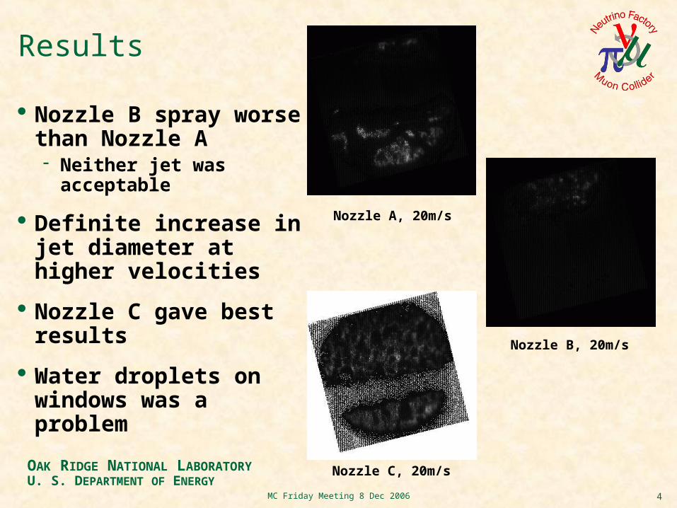
Results
Nozzle B spray worse than Nozzle A Neither jet was acceptable
Definite increase in jet diameter at higher velocities
Nozzle C gave best results
Water droplets on windows was a problem
Nozzle A, 20m/s
Nozzle B, 20m/s
Nozzle C, 20m/s
5MC Friday Meeting 8 Dec 2006
OAK RIDGE NATIONAL LABORATORYU. S. DEPARTMENT OF ENERGY
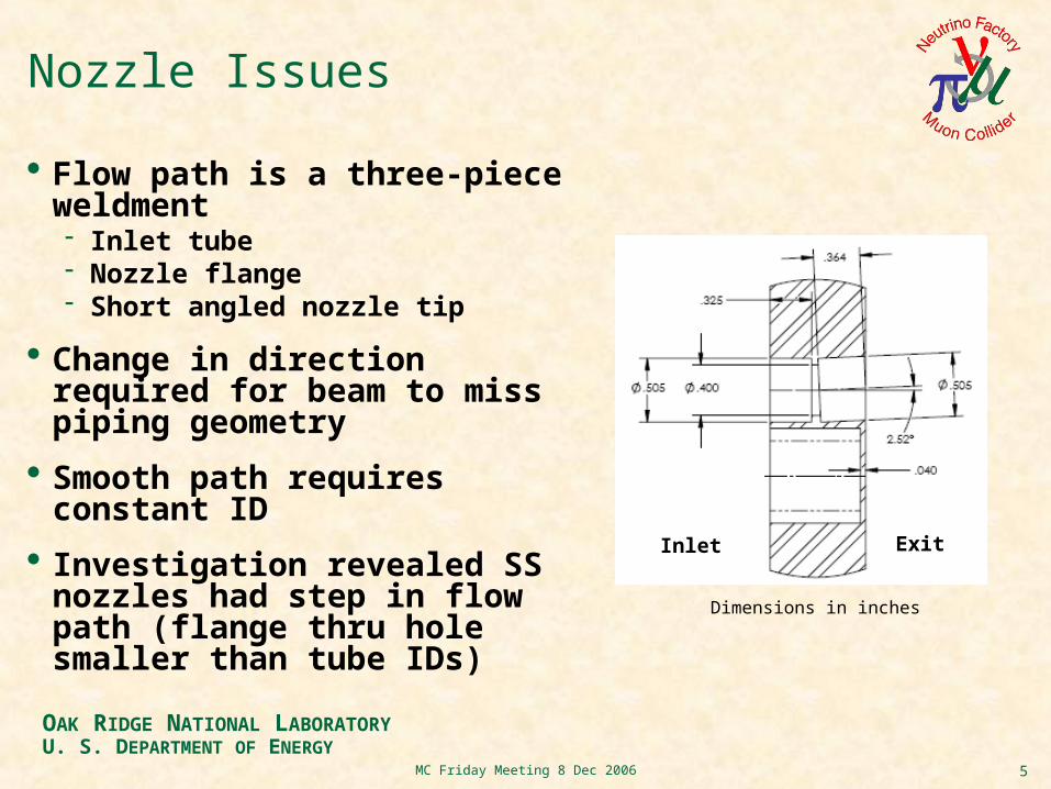
Nozzle Issues
Flow path is a three-piece weldment Inlet tube Nozzle flange Short angled nozzle tip
Change in direction required for beam to miss piping geometry
Smooth path requires constant ID
Investigation revealed SS nozzles had step in flow path (flange thru hole smaller than tube IDs)
Inlet Exit
Dimensions in inches
6MC Friday Meeting 8 Dec 2006
OAK RIDGE NATIONAL LABORATORYU. S. DEPARTMENT OF ENERGY
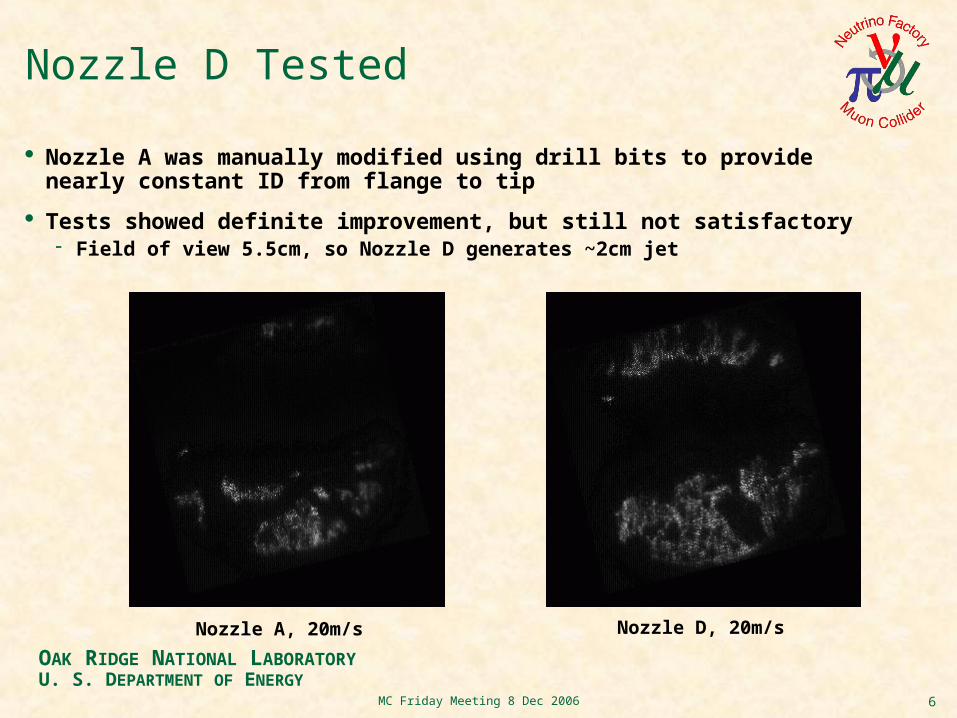
Nozzle D Tested
Nozzle A was manually modified using drill bits to provide nearly constant ID from flange to tip
Tests showed definite improvement, but still not satisfactory Field of view 5.5cm, so Nozzle D generates ~2cm jet
Nozzle A, 20m/s Nozzle D, 20m/s
7MC Friday Meeting 8 Dec 2006
OAK RIDGE NATIONAL LABORATORYU. S. DEPARTMENT OF ENERGY
Path Forward
Water test results discussed among MERIT collaboration
Best chance of success is to reproduce straight nozzle C Changing direction just before nozzle exit has not proven to
provide satisfactory results Piping still requires "kink" to avoid beam, but new design will
move kink in front of 180deg bend
New nozzles will be fabricated with Ti, the actual design material Enough Ti on hand to produce two configurations Machining and drawings ready for a Ti nozzle A Developing models and drawings for a new nozzle E
8MC Friday Meeting 8 Dec 2006
OAK RIDGE NATIONAL LABORATORYU. S. DEPARTMENT OF ENERGY
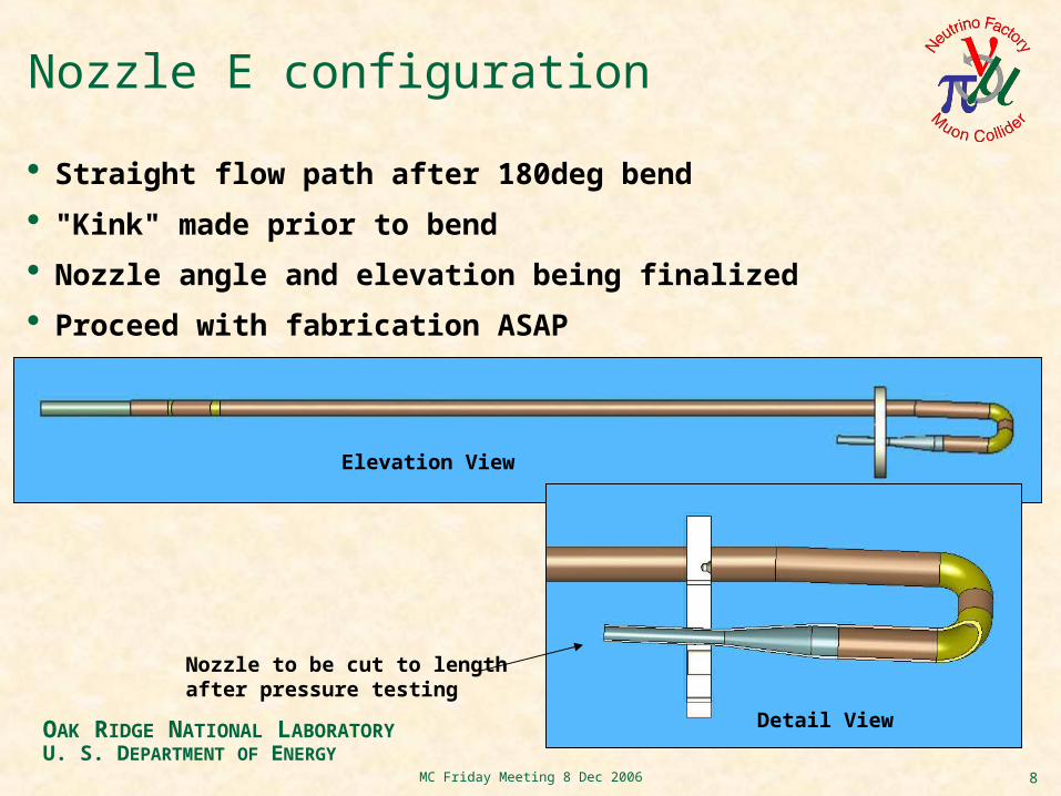
Nozzle E configuration
Straight flow path after 180deg bend
"Kink" made prior to bend
Nozzle angle and elevation being finalized
Proceed with fabrication ASAP
Elevation View
Detail View
Nozzle to be cut to lengthafter pressure testing
9MC Friday Meeting 8 Dec 2006
OAK RIDGE NATIONAL LABORATORYU. S. DEPARTMENT OF ENERGY
ORNL Readiness Review
Internal ORNL review held to determine if necessary steps are in place for mercury operations
No issues noted as long as safety equipment is in place and operating procedures are followed
MERIT collaboration discussing when to start Hg tests Use existing nozzles or wait for Ti versions Syringe has never been Hg tested Cannot switch back to water after Hg introduced Have to consider waste issues
10MC Friday Meeting 8 Dec 2006
OAK RIDGE NATIONAL LABORATORYU. S. DEPARTMENT OF ENERGY
Current Status / Next Steps
Fabricate Ti nozzle(s) immediately
Complete secondary containment Assemble and check for air leaks Install Hg vapor filters
Clean inside of viewports before introduction of Hg
Conduct Hg tests
Working on equipment transport issues Equipment crating is being fabricated


![[p.T] Stratigraphy Geologic Time](https://img.pdfslide.us/doc/110x75/577d34871a28ab3a6b8e3c40/pt-stratigraphy-geologic-time.jpg)


![[p.T] Petroleum Development Geology](https://img.pdfslide.us/doc/110x75/577d34871a28ab3a6b8e3c29/pt-petroleum-development-geology.jpg)