Embed Size (px)
Citation preview

WATER SYSTEM PERFORMANCE IN THE
GREAT HANSHIN (KOBE) EARTHQUAKE
Donald Ballantyne, PE
EQE International, Seattle, WA
ABSTRACT
The magnitude 6.8 Great Hanshin (Kobe) Earthquake produced peak ground
accelerations of 0.8 times gravity, impacting a large, very densely populated region of
western Japan. An estimated 2,000 water pipeline failures occurred in Kobe,
draining reservoirs, and limiting water available for fire suppression. Transmission
and distribution pipeline and water purification plant damage resulted in 300,000
people still without water, one month following the earthquake.
An aggressive earthquake mitigation program had replaced most of the City’s
cast iron pipe; without that program, failures and restoration time could have been far
greater. About 6 percent of Kobe’s ductile iron pipe had a special seismic joint that
appears to have had little or no damage. An earthquake monitoring and control
system isolated 18 reservoirs saving the water for drinking in the days following the
event.
INTRODUCTION
This paper describes the impact of the Great Hanshin Earthquake on City of
Kobe water system. An overview of the earthquake, regional seismology and
geology are presented. The operation of the water system is described followed by
earthquake effects on the water system. Finally, conclusions and recommendations
are drawn.
Earthquake Overview
The Great Hanshin (Kobe) Earthquake occurred at 5:46 AM on January 17,
1995. The magnitude 6.8 event, as measured by the USGS, heavily impacted an area
approximately 40 km along the causative fault, with the most severe damage
occurring within 3 km on either side of the fault. Peak ground accelerations were in
the order of 0.8 times gravity. Earthquake magnitude and peak ground accelerations
were similar to the Northridge Earthquake.
The earthquake was the most destructive event impacting a highly developed
country in modern times. The death toll reached near 5,300 people, with 300,000
people left homeless. Loss estimates exceed $100 billion, nearly an order of
magnitude larger than the Northridge Earthquake. The extreme destruction occurred
as a result of the correlation of high levels of ground shaking with a densely
populated area.

Overview of Impact on the Water System
Severe pipeline damage quickly drained most of the city’s reservoirs leaving
inadequate water for fire suppression. Drinking water was in short supply in the first
few days following the event. It took nearly three weeks to restore service to half the
customers in the hardest hit areas, and two months to reach 99 percent service
restoration.
Seismology and Geology
The earthquake was not expected. Japan is located at the juncture of the
Eurasian, Philippine, Pacific, and North American tectonic plates. However, the
Kobe Earthquake did not occur at a plate boundary. An earthquake of this magnitude
had not occurred in the Kobe area in nearly half a millennium. Only one earthquake
with a magnitude of 6 had occurred in the area in this century. As a result,
earthquake mitigation programs in other parts of Japan, such as Tokyo, have been
more aggressive than in Kobe.
Kobe is located on a narrow strip of land on the north side of Osaka Bay and
the Rokko Mountains. As a result of minimal land available for development, the
bay had been filled making manmade islands. Port Island, and Rokko were the most
recent additions. Fill was brought in from the Rokko Mountains and placed on soft
materials in the bay. The resulting soil structure was highly liquefiable as
demonstrated in the earthquake.
OVERVIEW OF WATER SYSTEM
System General Overview
The City of Kobe system serves 610,000 households including 1.5 million
people. The Kobe Water Department has over 1,000 employees. The system was
started in 1900. The City area is 547 square km of which 245 square km has water
service. The balance of the City is mountainous and undeveloped. The Kobe Water
system includes:
• 4,000 km pipe
• 240 reservoirs at 119 sites
• 43 pump stations with 208 pumps
• 57 km transmission tunnels
Figure 1 shows a schematic of the system.
Kobe’s water is pumped to the major water purification plants. Eighty-five
percent runs by gravity to the west through a tunnel system at an elevation of 90 m.
Water used at an elevation above 90 meters (approximately 15 percent of the
demand) is pumped from the tunnel system.

The tunnel system operates in the open channel flow or low pressure regime.
The first tunnel, 1.8-meter diameter, was constructed in the 1930's in rock with an
unreinforced concrete lining. The second rock tunnel, 2.5-meter diameter and built
in the 1950's, is lined with reinforced concrete. There is apparently no concern about
water quality degradation in the tunnel even through it is open channel flow.
The Kobe potable water system is designed to provide both water for drinking
and fire protection. There is no dedicated water system for fire suppression. There
are approximately 900 cisterns located throughout the City for use for fire
suppression.
Supplies
Nearly all Kobe's water comes from surface water supplies. Nearly three-
quarters of Kobe's water supply comes from the east with primary sources including
Lake Biwa and the Yodogawa River. Table 1 shows which sources feed the various
water purification plants. Figure 1 shows where many of these sources are located.
Water Treatment Plants
All Kobe's water is treated before it is distributed. There are eight water
purification plants treating potable water for Kobe, and one treating water for
industrial use. The three largest plants are Uegahara, Hanshin, and Sengari. The
Uegahara and Hanshin plants are immediately adjacent to one another, and are
located to the east of the City. The Sengari plant is located north/northeast of the
City. Table 1 summarizes the water treatment plant information.
Distribution
Kobe has had an aggressive pipeline replacement program that has resulted in
nearly 90 percent of their system being constructed of steel or ductile iron pipe.
Between 1978 and 1991 they replaced approximately 300 km of pipe. The results
were evident in a 1990 leakage survey where the Kobe system had 93.5 percent
effective use of their water compared to Tokyo which had 87.8 percent and Osaka
which had 92.7 percent. A breakdown of system pipe material is summarized in
Figure 2.
Approximately 6 percent of their ductile iron pipe employs special seismic
joints as depicted in Figure 3. These joints, Japan Water Works Association,
JWWA, Standard G 113 and 114, are specially designed to allow longitudinal
extension and compression but are restrained before they separate. The ductile iron
pipe with S joints is manufactured by both Kubota and Kurimoto, and is estimated to
cost 30 percent more than pipe without seismic joints. All new pipelines greater than
400 mm in diameter and all pipelines in reclaimed and landslide areas are required to
be constructed with this seismic resistant pipe. All major pipelines on Rokko Island
are constructed with this special seismic resistant joint.
The steel pipe Kobe uses employs butt welded joints. Pipe larger than 600
mm diameter is welded from both the interior and exterior; smaller diameter pipe
only from the exterior. Kobe Water uses polyethylene encasement, commonly
referred to as baggies, for external corrosion control for their ductile iron pipe. They
line larger diameter pipe with mortar, and smaller diameter pipe with epoxy. For
new service connections, they use High Impact Vinyl Pipe, thought to be similar to
PVC used in the United States.
Distribution Reservoirs and Pump Stations
The Kobe Water Department has an inventory of 240 service reservoirs at 119
sites. These include cast-in-place concrete (approximately 80 percent), and precast
concrete and welded steel (approximately 20 percent combined), and range in
capacity from 40 to 20,000 m3.
Nearly all the reservoirs are constructed with two at each site. Many of these
are single tank structures constructed with a dividing wall. This provides
redundancy for post-earthquake function and allows removing one from service for
cleaning without impacting service. Kobe does not use pressure reducing valves
between pressure zones as are commonly used in the United States. Rather, they use
control tanks, with flow from the upper pressure zone into the tank controlled by an
altitude valve.
Kobe Water has had a program to advance the design of reservoirs to meet the
wide range of requirements including general structural performance, earthquake
performance and corrosion resistance. At the Okuhirano Water Purification Plant
site, about seven years ago Kobe constructed two reservoirs at about the same time,
one using welded steel and the other using precast concrete. The objective was to be
able to evaluate the relative long-term performance of both designs. Figure 4 shows
a section of the steel reservoir. It is specially designed to accommodate radial
expansion during filling, similar to U.S. precast/post-tensioned concrete tank designs.
Inherent in the design is damping of earthquake forces exerted on the steel shell.
The damping is provided by a flexible fill material between the concrete wall and the
steel shell.
Pump station facilities have been conservatively designed to resist
earthquakes. All of Kobe's pump stations have either diesel generators on site (10
sites), or have a dual source of power from alternate substations.
Control System
The Kobe Water Control Center, building is located at the Okuhirano
Purification Plant. It monitors over 2000 points including reservoir level; tunnel
level; tunnel, transmission, and distribution flow; pump status; and access alarms. It
controls 469 components including pump on/off, rate-of-flow controllers, valve
controls, and control selection.

The Control Center communicates with distributed facilities through a
repeater station on the International Trade Center Building. That repeater serves
much of the urban area and the Uegahara Water Purification Plant directly and also
transmits secondary repeaters at:
• Mt. Rokko (serving Northern Service Area; Sengari Water
Purification Plant)
• Mt. Takao (serving Western area)
Figure 5 presents a schematic of the communication/repeater system.
Earthquake Monitoring and Control
Kobe Water has an earthquake monitoring and control system to isolate water
in selected reservoirs from the system to maintain it for drinking following an
earthquake. Without this system in place, the typical scenario would be that pipe
damage in the system would result in quickly draining the service reservoirs. The
system is not designed to save water for fire suppression. There is no system to
isolate major lines crossing vulnerable areas such as lines to the reclaimed land areas.
The system consists of earthquake ground motion monitoring at the
Okuhirano Control Center, a control panel, telemetry (as described above), and
reservoirs with earthquake isolation valves at 21 locations, and plans for a total of 26
locations. The earthquake valves are motor operated with backup batteries.
An instrument at the Control Center, shown in Figure 6, measures ground
motion, and provides input into the earthquake control system shown in Figure 7.
The earthquake control system allows both automated and manual control of isolation
valves on service reservoirs. The decision logic is as follows:
Peak Ground Acceleration Control Thresholds
1. 40 gal - manual alarm (980 gal = 1 x gravity)
2. 80 gal - automatic shut down when combined with excessive rate of
change of flow
3. 250 gal - automatic shut down
There are dual reservoirs at each of 21 sites; one has an isolation valve to be
controlled following an earthquake, and one does not. This concept allows shutdown
of one reservoir while maintaining service should the second reservoir inadvertently
shutdown. If the system can keep up with system leakage, the isolated reservoir can
be put back on line from the Control Center. If the system can not keep up with the
demand, reservoir remains isolated.
Emergency planners based the number of reservoirs with isolation valves on
the capacity required to provide the population 3 liters/day for drinking for 7 days.
Planners estimated that it would take up to 7 days to repair the system. Isolated tanks
were selected so that each would serve an area approximately 4 km in diameter.

CONDITIONS FOLLOWING THE EARTHQUAKE
Earthquake valves closed on 18 of 21 service reservoirs following earthquake
storing 33,800 m3 of water. Storage before the earthquake (1/17 at 5:05 AM) was
338,455 m3. The earthquake occurred at 5:46 AM. Minimum storage after the
earthquake (1/18 at 6:01 AM) was 94,908 m3.
The 86 distribution reservoirs serving the urban area without earthquake
valves quickly emptied as shown in Figure 8. This resulted in inadequate water
available for fire suppression of the 350 fires that broke out in the first two days
following the earthquake.
Figure 9 shows the ignition and fuel source of a group of these fires assessed
during the earthquake aftermath. It is believed that some of the fires resulted when
the electrical system was reenergized, and resulting sparks from shorts started fires.
There may be an opportunity to mitigate some of these fires by employing an
earthquake switch on electrical services that must be manually reset.
Water carried to the Hanshin Purification Plant was reduced from 6,000 to
1,000 m3/hr immediately following the earthquake. This was caused by loss of
power to Yodogawa River Pump Stations for 15 hours following the earthquake as
well as transmission main breaks.
When service was resumed, the chlorine feed rate at the purification plant was
increased but no boil water notice was issued. When leaks were repaired, lines were
flushed, but not disinfected.
Emergency supply using water tank trucks was initiated on the evening of
January 17. Later, water supply aid came from other cities and from the Self Defense
Forces. Regular water supply points were established and increased in numbers as
time went on as shown in Figure 10.
Starting January 18, water restoration began. Leaks were identified and
repaired with the following priorities:
1. Damaged areas, medical facilities, areas with large populations.
2. Broken pipes, minor leakage areas (that is fix areas that first that
could be easily restored).
3. Broken pipes, major leakage areas.
4. Shelters and areas in danger of landslides.
Water Department crews worked from the outside in. Mutual aid was
provided by 37 agencies including an estimated 1,000 people. Figure 10 shows the
status of emergency water supply in the days following the earthquake in terms of
truck loads of water, distribution points, and relief workers working on water
distribution. It is not clear what the correlation is between trucking in water and use
of the service reservoirs that had been isolated for local distribution for drinking.

Figure 11 shows the number of of emergency response workers from other
cities assisting in restoration of the pipeline system and purification and pump station
equipment, respectively. Based on the information provided by the Kobe Water
Department shown in these figures, it appears that it took approximately one week to
get mutual aid in place.
Figure 12 shows the status of both the electric and water systems restoration
for the two months following the earthquake. Note how quickly the power system
was restored compared to the water system. Approximately three-quarters of this
system was initially without service. The western area of the system was the most
severely impacted, while the northern part of the system had the least damage. Water
was restored to 99 percent of customers by March 29.
Figure 13 shows restoration (filling) of distribution reservoirs and water
mains. The Hokushin and Rokko Mountain reservoirs were restored within about 4
days, after which the total reservoir and Shigaichi (urban area)reservoir curves are
parallel. Distribution main restoration lags behind restoration of the reservoirs, as
expected.
DAMAGE TO WATER FACILITIES
This section describes damage to specific system components.
Supply Reservoirs
The two original in-town reservoir impoundments suffered some damage as
listed below.
• Nunobiki Reservoir - cracked hand rail in walkway on dike. Damage
to foot of service bridge requiring major repairs.
• Karasuhara Reservoir - vertical crack at one location on back of dike.
Water Purification Plants
The Uegahara, Hanshin and Motoyama water purification plants were
damaged. The Sengari, Okuhirano, and Sumiyoshi water purification plants had little
damage. Information is not available on the other two small plants, Arima and Mt.
Rokko.
Uegahara Water Purification Plant - The plant was rendered inoperable
following the earthquake. On the west side of the plant (Figure 14, at 10 o’clock
from the large circular structure), fill behind a retaining wall subsided approximately
30 cm when the retaining wall moved outward resulting in separating pipeline joints
on three treated water lines in an area 100 m long. Each pipe was constructed of 1.2
m diameter reinforced concrete. The lines were the 1) Uegahara potable water, 2)

Uegahara industrial water, and 3) Hanshin potable pipelines. The Hanshin line was
operating as of February 12.
The solids handling building was located in the same area that subsided. The
floor settled differentially. There was subsidence around pile supported foundation
of sludge hoppers as shown in Figure 15. Unanchored electrical equipment toppled
in sludge thickener building. The building and adjacent sludge hoppers were pile
supported, so the cross section of the slope/retaining/fill is unclear.
This same subsidence also probably led to the following damage:
• Clarifiers - damage to expansion joints; water leakage
• Process Tanks - some leakage
• Sludge Thickening Equipment - extensive damage to piping and
equipment
• High Rate Filter Piping - bent and disconnected
• Other - damage to pipe, mechanical, and electrical equipment.
Steel baffles in the clarifiers were damaged from impulsive hydraulic forces.
Hanshin Water Authority Water Purification Plant - The plant was not
damaged and operating at 3000 m3/hr as of February 12. There was a major
landslide, the largest slide in the urban area in the Kobe Earthquake, in back of
(northeast of) the treatment plant (Figure 14, right middle) , undercutting the
wastewater treatment building which was pile supported (Figure 16), and destroying
a tennis court and a sludge drying bed. The slide killed 36 people in a housing
development below, and dammed the Nigawa River. The slide is the responsibility
of Hyogo Prefecture . The original slope was 18 degrees, much less than the 30
degrees where the code requires mitigation. They had placed plastic covering area
above slide to keep rain off, slope monitoring in place, and had started to do borings
to further investigate the slide. Peak accelerations in the area appeared to be
moderate as damage to buildings in the area was light, with only occasional roof
damage.
Motoyama Water Purification Plant - The Motoyama Plant had damage to
two segments of pipelines and minor cracking to a process tank. Pipelines to and
from the backwash water tank failed as a result of slope failure.
The retaining wall along side the Simiyoshi River moved, breaking the intake
box overflow line. Water is fed to the intake box through a pipeline connected to a
small diversion structure in the river upstream of the plant. There was a concern that
the cast iron raw water line running from the intake box to the treatment plant may
have been damaged as a result of the retaining wall movement, and needed to be
checked before it was put into operation. The property owners, just above the suspect
raw water line are uneasy; because they did not want a break to undermine their
house.

Intake, Pump Stations, and Transmission Pipelines
The intakes in and pump stations near the Yodogawa River were not
damaged. The two major lines from the Yodogawa River were broken in 10
locations. One ductile iron line had a split 30 cm long and 5 cm wide. One 100
meter section had to be replaced. It took 12 days to repair the raw water lines serving
the plant.
The Mt. Rokko Tunnels, carrying water from the Uegahara and Hanshin
plants west, to be distributed, had not been inspected on the interior when
information was collected for this paper, but no major leakage was occurring and
only minor damage was expected.
Pump stations were undamaged. Damage to air release valves was reported.
Distribution Reservoirs (Tanks)
Of the 119 reservoir sites throughout the City, there was damage to one pre-
World-War-II cast-in-place partially buried concrete tank, where there was a crack on
the bottom and side.
At the Egeyama Reservoir, there was leakage in the pipe connecting the
reservoir and the adjoining well, and a vertical crack in the expansion joint. A 500
mm diameter pipe 10 meters long was replaced.
Distribution Pipes
Distribution pipeline damage as of March 29 was reported as listed below.
An additional 10 percent of pipe failures were expected to be identified.
Distribution pipes (75-300 mm) 1,800
Service Lines (<75 mm) 10,000
Total 11,800
Figure 17 shows the distribution of pipe failure mechanisms, with
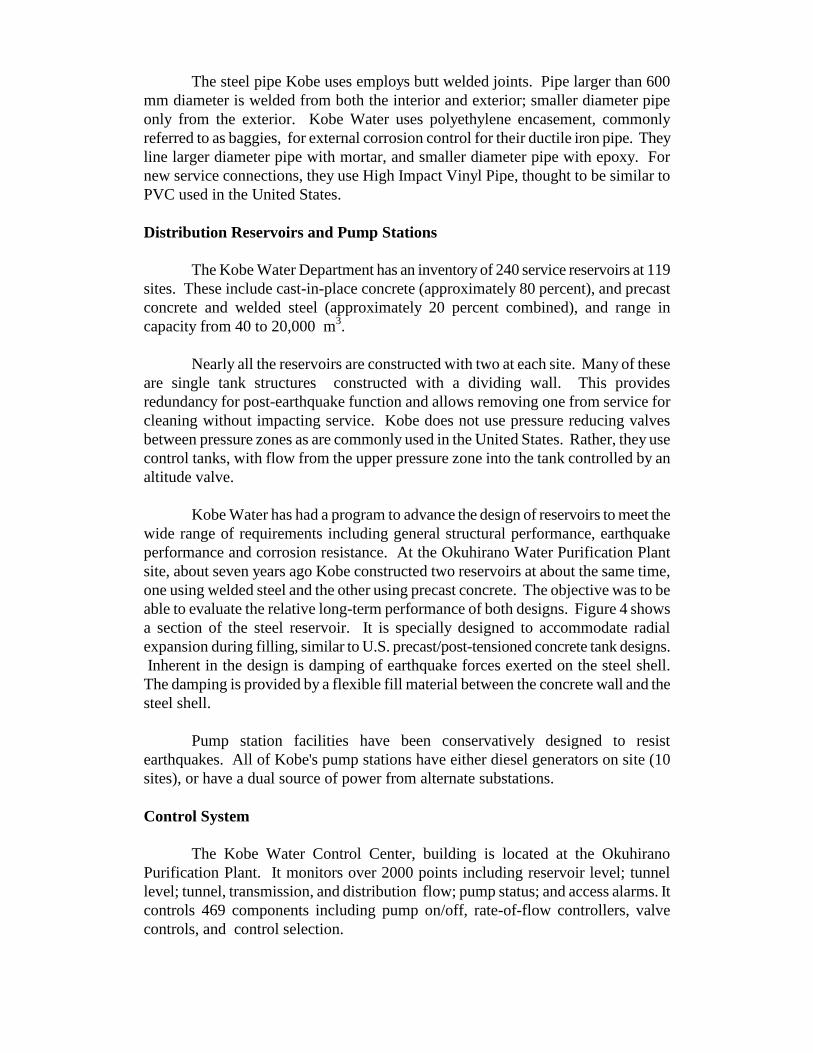
approximately two-thirds being from pulled joints. Figure 18 shows lateral spreading
that resulted in the joint separation shown in Figure 19. Approximately 80 percent of
the pipe in the system was ductile iron, so damaged pipe segments were minimized.
The three predominant types of service line failures were 1) house collapse, 2)
joint separation, and 3) failure where the line passed below the concrete stromwater
gutter. Areas of significant differential settlement between pile-supported and non-
pile-supported pipe also resulted in damage to pipe connections to buildings as
shown in Figure 20. Service line repairs were being accomplished at a rate of 2 per
day with a crew of 5 to 6 workers.
There was significant pipeline damage on Kobe's Port Island where Tyton-
type and/or mechanical joints were deployed. In contrast, there was very little water

pipeline damage on Rokko Island where the great majority of mains were ductile iron
pipe with S-type joints.
As the distribution system repair was nearing completion, water demand was
more than 30 percent greater than pre-earthquake use. There was concern that there
were still many leaks that had not been identified.
There were two major issues identified that had delayed system restoration:
• No water pressure was available to check the repairs while the tunnels
remained out of service.
• Access - limited by collapsed buildings and traffic congestion.
However it was noted that there were adequate repair materials.
Pipelines hung on the Kobe, Rokko, Mikage, and Fukae bridges were
damaged, and in some cases disrupted service to these islands.
Water Department Buildings
The Water Department Main Office, including administration and
engineering, was located on the 6th floor of the Old City Hall Building (City Hall
Annex). The 6th floor of the 8 story concrete frame building pancaked as shown in
Figure 21. Because of the early morning hour, only one employee was inside, and
was killed. Distribution system maps, facility drawings, etc. were not available
during the initial restoration phase.
The Water Department maintained a distribution and maintenance buildings
in five wards throughout the City. The upper three floors of the eight story Water
Department Eastern Center partially collapsed. The Western Center partially burned.
The unburned section was being used. The combined damage of these three
facilities made emergency response and restoration very difficult. The Central,
North, and Tarumi Centers were not damaged.
Monitoring and Control System
The control system designed to isolate 21 reservoirs for drinking worked at 18
locations, and water was saved for drinking. Two of the failures were electrical or
mechanical and 1, hydraulic. The three repeater stations and telemetry systems were
undamaged.
LESSONS FOR U.S. AND AREAS REQUIRING RESEARCH
Overwhelming Conditions
In the United States, we need to be aware of the potential magnitude of
earthquake consequences. This large earthquake had the most direct impact on urban

area in a country with development comparable to the United States. The results
were overwhelming in terms of loss of life and property damage, as well as poor
performance of utility systems.
From an emergency response perspective, there is always discussion about
what might occur following a large earthquake located in a densely populated area. It
is beyond comprehension for most people outside California that such an event will
happen, and therefore they do not truly consider the consequences. One of the
biggest issues following the Kobe event was transportation; being able to get to
where one needed to go. Every major transportation route had failed, and surface
roads were blocked by fallen buildings. The resulting congestion made walking the
fastest form of transportation. The result was that emergency response slowed to a
crawl.
The same situation was true for response of utility personnel. For moderate
earthquakes, there was an emergency response plan to enable effective data
acquisition and response. Utility decision makers need to be thinking of
consequences similar in magnitude to the Kobe event. For example, what happens
when you have no records when utility buildings are destroyed? What happens if the
plan is to dispatch crews to isolate critical pipelines to save water or shut off natural
gas, and the fastest way to get there is to walk?
Fire Following
In the U.S., we need to refocus on the issue of fire following earthquakes.
While there was no fire storm, there were 350 ignitions, and in many cases no water
to suppress them. Water purveyors and fire departments should evaluate the
vulnerability of water supplies. Recent earthquakes have shown that there is a low
probability of maintaining a water system following an earthquake. Consideration
should be given to identifying and developing alternate supplies.
Similarly, the use of monitoring and control systems should be considered to
enable timely control of water systems following an earthquake to increase the
probability of delivering water to suppress fires.
Water purveyors and fire departments should use liquefaction and landslide
hazard mapping coupled with Geographic Information Systems to identify areas
where pipelines will likely fail so that plans can be made to isolate damaged areas
and/or use alternative water supplies.
Geotechnical Issues
In the U.S., we need to refocus on the potential consequences of geotechnical
failures. Many lifeline system owners are lulled into an earthquake program that
includes non-structural upgrades, and minor building strengthening. Geotechnical
hazards are considered, and the potentially dramatic consequences identified, but
dropped when high mitigation costs are presented.

In Kobe, geotechnical failures governed the poor performance of the water
system. Landslides, consolidation, and liquefaction/lateral spread stopped the flow of
water from the source, damaged two major, and one smaller water treatment plant,
and took a heavy toll on the distribution system. The treatment plant structures
performed reasonably well except that they were founded on soils that failed. An
aggressive pipeline replacement program apparently only marginally helped mitigate
geotechnical failure-related damage to the pipeline distribution system.
Design
Water treatment plants and service reservoirs performed well. We should
study Japanese design approaches for these facilities. Their modern tank designs are
somewhat different than those used in the U.S., and apparently had no damage when
subjected to high peak ground accelerations.
Pipelines were heavily damaged. Preliminary information on performance of
the S joint pipe appears that it had no or few failures. If it is confirmed that it
performed well in areas of significant of permanent ground deformation, we should
introduce it, or a similar design into the U.S.. If it did not perform well, we should
find out why, and improve U.S. pipe designs based on those findings.
An estimated 65 percent of the pipeline failures were pulled joints. As 80
percent of the pipe inventory in Kobe was ductile iron pipe with Tyton or mechanical
joints without restraint, we should not become complacent with use of non-restrained
joints in areas expecting significant permanent ground deformation.
Recovery
Three Kobe Water buildings storing records were destroyed. The probability
of this occurring is very low. In the U.S., we should make sure that our resources are
distributed so that loss of any one facility will not substantially impact our ability to
respond to an earthquake.
Summary
The Great Hanshin Earthquake left one million households without water
following the event, with only 80 percent restoration in one month. Water for fire
suppression was substantially exhausted after six hours.
The two large diameter transmission lines carrying water from the Yodogawa
River to the Uegahara and Hanshin water purification plants failed in ten locations.
This source constitutes nearly three-quarters of Kobe's supply. The Uegahara and
Hanshin plants are Kobe's largest. In addition to their supplies being disrupted, soil
failures at the plants resulted in failure of the major treated water lines, as well as
moderate damage at the plants themselves.
The tunnels carrying water from the plants west to Kobe remained intact,
expected performance of tunnels in earthquakes. Kobe Water had an aggressive

earthquake design program for at least some of their service reservoirs. There was
one tank failure reported for their 240 tanks at 119 sites. There was one connecting
piping failure at one tank.
Nearly 90 percent of Kobe's water distribution system was made up of either
welded steel or ductile iron pipe, both thought to be resistant to earthquakes. This
unusually high percentage of pipe resulted from an aggressive pipeline replacement
program initiated in the mid-1960's. Even with this in place, an estimated 2,000
pipeline failures occurred in distribution piping, 1.5 times as many as occurred in the
Northridge Earthquake. Much of this damage is associated with joint separation
associated with liquefaction/lateral spreading.
Kobe had implemented a monitoring and control system designed to isolate
reservoirs following an earthquake to be used for drinking. The system worked as
designed. It needs to determine if they would have been better off focusing their
mitigation efforts on water for fire suppression.
There was no system focused on post-earthquake performance to provide
water for fire suppression. There was no water available to put out many of the 350
ignitions.
The lifeline earthquake community in the U.S. should learn from both the
successes and failures observed in Kobe. Successes include the monitoring and
control system, performance of water treatment plants (except geotechnical), tankage,
and seismic joint pipe. Failures include lack of adequate water supply for fire
suppression (including alternate supplies), and inadequate focus on geotechnical
issues.
ACKNOWLEDGMENTS
This paper summarizes reports prepared by the author for the National Center
for Earthquake Engineering Research and the National Institute fir Standards and
Technology.
The author would like to thank Professor Takada at Kobe University and Mr.
Matsushita at the Kobe Water Department for providing information on the Kobe
water system both before the earthquake (October, 1993), and following the
earthquake. Dr. Ian Austin, Mr. Fumihiro Kujihara and Mr. Ken Sasaki of all from
Chiyoda-Dames & Moore in Tokyo, who made local arrangements, provided
translation, and traveled with Mr. Ballantyne in Kobe. Their assistance is greatly
appreciated. Contributions to the original reports are also gratefully acknowledged
from Professor Tom O'Rourke, Cornell University, and Messrs John Eidinger and
LeVal Lund who provided information gathered on the ASCE TCLEE
reconnaissance trip to Kobe.

Table 1
Water Treatment Plants Serving Kobe
Purification Plant
Source
Capacity/day (1000 m
3)
Uegahara (industrial)
Yodogawa River
150
Hanshin (1)
Yodogawa River
144
Uegahara (potable) (2)
Sengari Reservoir
128
Sengari
Sengari Reservoir
108
Okuhirano (3)
Nonobiki, Karasuhara
Reservoirs
60
Motoyama
Sumiyoshi River
8 (4)
Sumiyoshi
Sumiyoshi River
6
Mt. Rokko
1
Arima
0.3
Notes:
1. Municipal corporation including Kobe, Ashiya, Nishinomiya, and
Amagasaki.
2. The Hanshin Water Authority Water Treatment Plant is immediately
adjacent to the Uegahara Water Purification Plant. Uegahara uses sodium
hypochlorite for disinfection.
3. Also houses control center.
4. Usually runs at 6000 m3, including 1000 m
3 to Saki plant in summer and
2000 m3 in winter.

Figure 2 - Kobe Water Pipe Material Break Down.
Figure 3 - Seismic Joints, (S and SII).

Figure 4 - Tank Section at Okuhirano Purification Plant.
Figure 5 - Schematic of Communication/Repeater System.

Figure 6 - Ground motion instrument at the Control
Center controlled earthquake valves.
Figure 7 - Schematic of Communication from Ground Motion
Instrument to the Earthquake Valve.

Figure 8 - Water Loss From Reservoirs After Earthquake.
Figure 9 - Fire Ignition / Fuel Source.
Figure 10 - Status of Emergency Water Supply.

Figure 11 - Mutual Aid from Other Cities Repairing
Pipelines and Equipment.
Figure 12 - Water / Electricity Restoration.
Figure 13 - Restoration of Distribution Reservoirs and Water Mains

Figure 14 - Aerial view of Uegahara Purification Plant (lower left)
with the Hanshin Water Purification Plant
immediately adjacent (upper right).
Figure 15 -
Subsidence
(approximately
30 cm) around
pile-supported
sludge hoppers
at Uegahara
Plant.
Figure 16 -
Landslide
undermined
solids handling
building
at the
Hanshin
Plant.

Figure 17 - Distribution of Pipe Failure Mechanisms
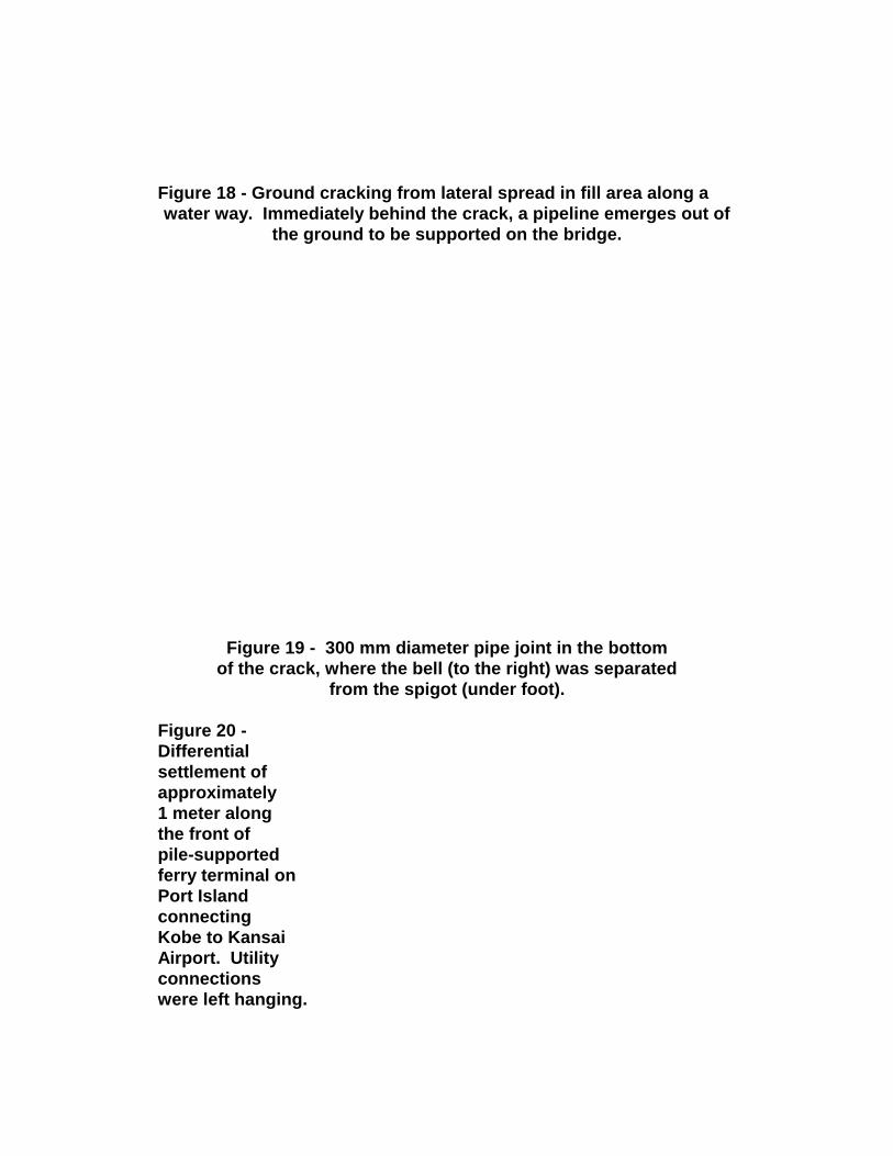
Figure 18 - Ground cracking from lateral spread in fill area along a
water way. Immediately behind the crack, a pipeline emerges out of
the ground to be supported on the bridge.
Figure 19 - 300 mm diameter pipe joint in the bottom
of the crack, where the bell (to the right) was separated
from the spigot (under foot).
Figure 20 -
Differential
settlement of
approximately
1 meter along
the front of
pile-supported
ferry terminal on
Port Island
connecting
Kobe to Kansai
Airport. Utility
connections
were left hanging.

Figure 21 - Pancaked 6th Floor of City Hall Annex.