Embed Size (px)
Citation preview
Wat
erFu
rnac
e
SP2600 03/09
Design Features
Factory Options
Accessories
Dimensional Data
Physical Data
Performance Data
Engineering Guide Specifications
Water Source/Geothermal Heat Pumps3/4 thru 6 Ton Horizontal•3/4 thru 5 Ton Vertical•
Vers
atec
Spe
cific
atio
n C
atal
og

3
VERSATEC SPECIFICATION CATALOG
Table of Contents
ARI Data 5-6
Model Nomenclature 7
Design Features 8-10
Controls - FX10 11-14
Vertical Dimensional Data 15-19
Horizontal Dimensional Data 20
Vertical Electrical Data 21
Horizontal Electrical Data 22
Vertical Fan Performance Data 23
Horizontal Fan Performance Data 24
Vertical Physical Data 25
Horizontal Physical Data 25
Reference Calculations 26
Legend and Notes 26 Correction Factors 27-28
Capacity Data 29-49
EngineeringGuideSpecifications 50
4
VERSATEC SPECIFICATION CATALOG
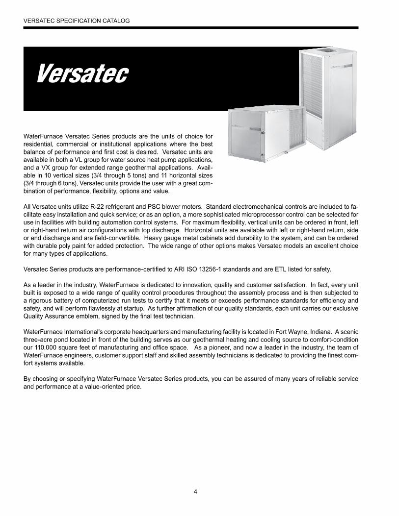
WaterFurnace Versatec Series products are the units of choice for residential, commercial or institutional applications where the best balance of performance and first cost is desired. Versatec units are available in both a VL group for water source heat pump applications, and a VX group for extended range geothermal applications. Avail-able in 10 vertical sizes (3/4 through 5 tons) and 11 horizontal sizes (3/4 through 6 tons), Versatec units provide the user with a great com-bination of performance, flexibility, options and value.
All Versatec units utilize R-22 refrigerant and PSC blower motors. Standard electromechanical controls are included to fa-cilitate easy installation and quick service; or as an option, a more sophisticated microprocessor control can be selected for use in facilities with building automation control systems. For maximum flexibility, vertical units can be ordered in front, left or right-hand return air configurations with top discharge. Horizontal units are available with left or right-hand return, side or end discharge and are field-convertible. Heavy gauge metal cabinets add durability to the system, and can be ordered with durable poly paint for added protection. The wide range of other options makes Versatec models an excellent choice for many types of applications.
Versatec Series products are performance-certified to ARI ISO 13256-1 standards and are ETL listed for safety.
As a leader in the industry, WaterFurnace is dedicated to innovation, quality and customer satisfaction. In fact, every unit built is exposed to a wide range of quality control procedures throughout the assembly process and is then subjected to a rigorous battery of computerized run tests to certify that it meets or exceeds performance standards for efficiency and safety, and will perform flawlessly at startup. As further affirmation of our quality standards, each unit carries our exclusive Quality Assurance emblem, signed by the final test technician.
WaterFurnace International's corporate headquarters and manufacturing facility is located in Fort Wayne, Indiana. A scenic three-acre pond located in front of the building serves as our geothermal heating and cooling source to comfort-condition our 110,000 square feet of manufacturing and office space. As a pioneer, and now a leader in the industry, the team of WaterFurnace engineers, customer support staff and skilled assembly technicians is dedicated to providing the finest com-fort systems available.
By choosing or specifying WaterFurnace Versatec Series products, you can be assured of many years of reliable service and performance at a value-oriented price.
5
VERSATEC SPECIFICATION CATALOG
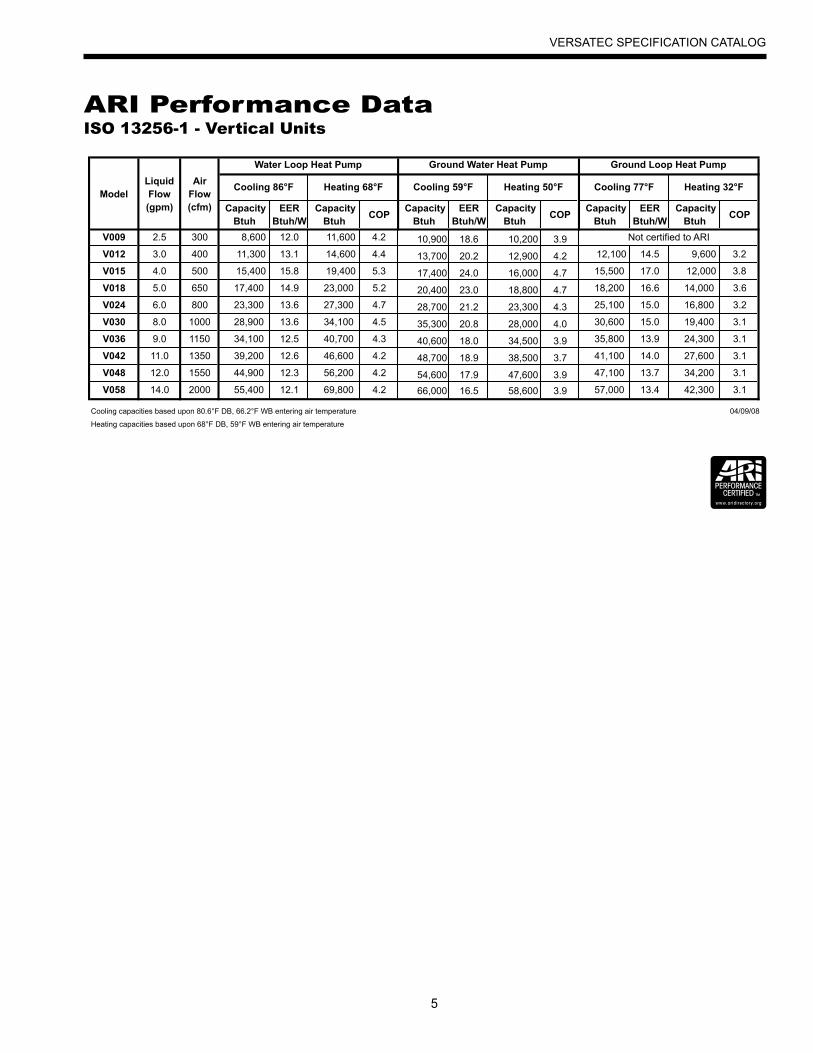
ARI Performance DataISO 13256-1 - Vertical Units
ModelLiquid Flow
Air Flow
Cooling 86°F Heating 68°F Cooling 59°F Heating 50°F Cooling 77°F Heating 32°F
(gpm) (cfm) Capacity Btuh
EER Btuh/W
Capacity Btuh
COP Capacity
Btuh EER
Btuh/W Capacity
Btuh COP
Capacity Btuh
EER Btuh/W
Capacity Btuh
COP
V009 2.5 300 8,600 12.0 11,600 4.2 10,900 18.6 10,200 3.9
V012 3.0 400 11,300 13.1 14,600 4.4 13,700 20.2 12,900 4.2 12,100 14.5 9,600 3.2
V015 4.0 500 15,400 15.8 19,400 5.3 17,400 24.0 16,000 4.7 15,500 17.0 12,000 3.8
V018 5.0 650 17,400 14.9 23,000 5.2 20,400 23.0 18,800 4.7 18,200 16.6 14,000 3.6
V024 6.0 800 23,300 13.6 27,300 4.7 28,700 21.2 23,300 4.3 25,100 15.0 16,800 3.2
V030 8.0 1000 28,900 13.6 34,100 4.5 35,300 20.8 28,000 4.0 30,600 15.0 19,400 3.1
V036 9.0 1150 34,100 12.5 40,700 4.3 40,600 18.0 34,500 3.9 35,800 13.9 24,300 3.1
V042 11.0 1350 39,200 12.6 46,600 4.2 48,700 18.9 38,500 3.7 41,100 14.0 27,600 3.1
V048 12.0 1550 44,900 12.3 56,200 4.2 54,600 17.9 47,600 3.9 47,100 13.7 34,200 3.1
V058 14.0 2000 55,400 12.1 69,800 4.2 66,000 16.5 58,600 3.9 57,000 13.4 42,300 3.1
Cooling capacities based upon 80.6°F DB, 66.2°F WB entering air temperature 04/09/08
Heating capacities based upon 68°F DB, 59°F WB entering air temperature
Water Loop Heat Pump Ground Water Heat Pump Ground Loop Heat Pump
Not certified to ARI
6
VERSATEC SPECIFICATION CATALOG
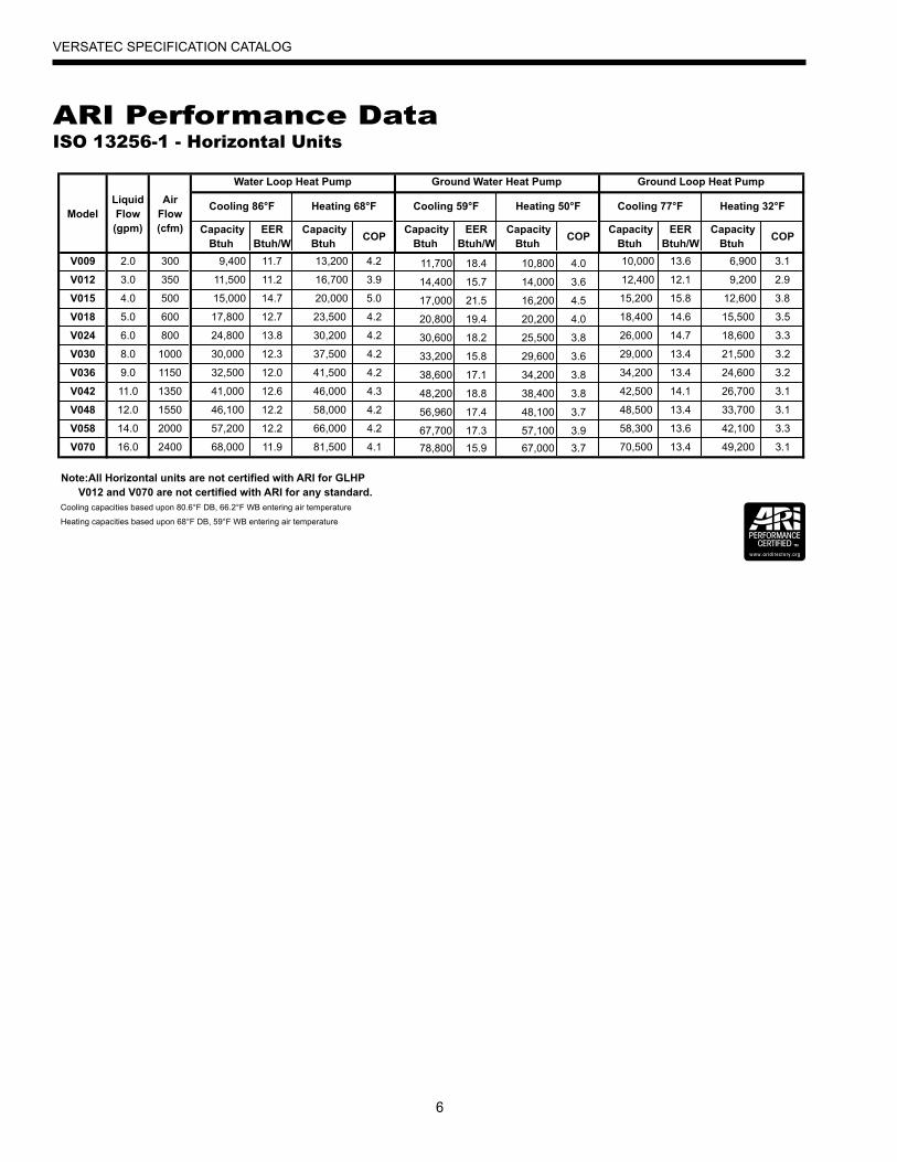
ARI Performance DataISO 13256-1 - Horizontal Units
ModelLiquid Flow
Air Flow
Cooling 86°F Heating 68°F Cooling 59°F Heating 50°F Cooling 77°F Heating 32°F
(gpm) (cfm) Capacity Btuh
EER Btuh/W
Capacity Btuh
COP Capacity
Btuh EER
Btuh/W Capacity
Btuh COP
Capacity Btuh
EER Btuh/W
Capacity Btuh
COP
V009 2.0 300 9,400 11.7 13,200 4.2 11,700 18.4 10,800 4.0 10,000 13.6 6,900 3.1
V012 3.0 350 11,500 11.2 16,700 3.9 14,400 15.7 14,000 3.6 12,400 12.1 9,200 2.9
V015 4.0 500 15,000 14.7 20,000 5.0 17,000 21.5 16,200 4.5 15,200 15.8 12,600 3.8
V018 5.0 600 17,800 12.7 23,500 4.2 20,800 19.4 20,200 4.0 18,400 14.6 15,500 3.5
V024 6.0 800 24,800 13.8 30,200 4.2 30,600 18.2 25,500 3.8 26,000 14.7 18,600 3.3
V030 8.0 1000 30,000 12.3 37,500 4.2 33,200 15.8 29,600 3.6 29,000 13.4 21,500 3.2
V036 9.0 1150 32,500 12.0 41,500 4.2 38,600 17.1 34,200 3.8 34,200 13.4 24,600 3.2
V042 11.0 1350 41,000 12.6 46,000 4.3 48,200 18.8 38,400 3.8 42,500 14.1 26,700 3.1
V048 12.0 1550 46,100 12.2 58,000 4.2 56,960 17.4 48,100 3.7 48,500 13.4 33,700 3.1
V058 14.0 2000 57,200 12.2 66,000 4.2 67,700 17.3 57,100 3.9 58,300 13.6 42,100 3.3
V070 16.0 2400 68,000 11.9 81,500 4.1 78,800 15.9 67,000 3.7 70,500 13.4 49,200 3.1
Note:All Horizontal units are not certified with ARI for GLHP
Cooling capacities based upon 80.6°F DB, 66.2°F WB entering air temperature
Heating capacities based upon 68°F DB, 59°F WB entering air temperature
Water Loop Heat Pump Ground Water Heat Pump Ground Loop Heat Pump
V012 and V070 are not certified with ARI for any standard.
7
VERSATEC SPECIFICATION CATALOG
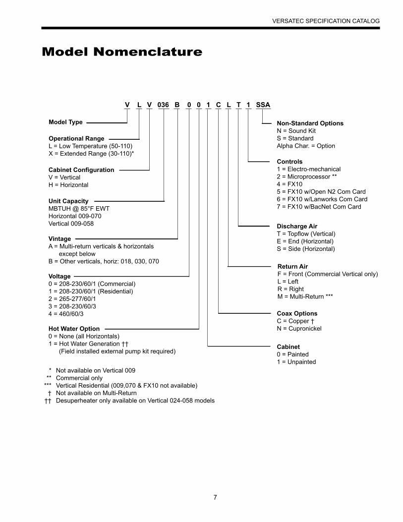
Model Nomenclature
Model Type
Cabinet ConfigurationV = VerticalH = Horizontal
Unit CapacityMBTUH @ 85°F EWTHorizontal 009-070Vertical 009-058
VintageA = Multi-return verticals & horizontals except belowB = Other verticals, horiz: 018, 030, 070
Voltage0 = 208-230/60/1 (Commercial)1 = 208-230/60/1 (Residential)2 = 265-277/60/13 = 208-230/60/34 = 460/60/3
Cabinet0 = Painted1 = Unpainted
Coax OptionsC = Copper †N = Cupronickel
Return AirF = Front (Commercial Vertical only)L = LeftR = RightM = Multi-Return ***
Discharge AirT = Topflow (Vertical)E = End (Horizontal)S = Side (Horizontal)
Controls1 = Electro-mechanical2 = Microprocessor **4 = FX105 = FX10 w/Open N2 Com Card6 = FX10 w/Lanworks Com Card7 = FX10 w/BacNet Com Card
Non-Standard OptionsN = Sound KitS = StandardAlpha Char. = Option
Operational RangeL = Low Temperature (50-110)X = Extended Range (30-110)*
Hot Water Option0 = None (all Horizontals)1 = Hot Water Generation †† (Field installed external pump kit required)
V L V 036 B 0 0 1 C L T 1 SSA
***
***†
††
Not available on Vertical 009Commercial onlyVertical Residential (009,070 & FX10 not available)Not available on Multi-ReturnDesuperheater only available on Vertical 024-058 models
8
VERSATEC SPECIFICATION CATALOG
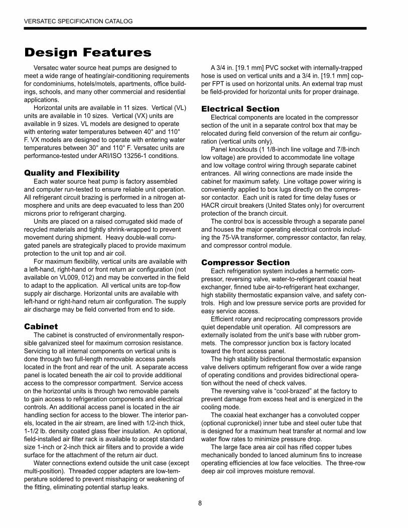
Versatec water source heat pumps are designed to meet a wide range of heating/air-conditioning requirements for condominiums, hotels/motels, apartments, office build-ings, schools, and many other commercial and residential applications.
Horizontal units are available in 11 sizes. Vertical (VL) units are available in 10 sizes. Vertical (VX) units are available in 9 sizes. VL models are designed to operate with entering water temperatures between 40° and 110° F. VX models are designed to operate with entering water temperatures between 30° and 110° F. Versatec units are performance-tested under ARI/ISO 13256-1 conditions.
Quality and FlexibilityEach water source heat pump is factory assembled
and computer run-tested to ensure reliable unit operation. All refrigerant circuit brazing is performed in a nitrogen at-mosphere and units are deep evacuated to less than 200 microns prior to refrigerant charging.
Units are placed on a raised corrugated skid made of recycled materials and tightly shrink-wrapped to prevent movement during shipment. Heavy double-wall corru-gated panels are strategically placed to provide maximum protection to the unit top and air coil.
For maximum flexibility, vertical units are available with a left-hand, right-hand or front return air configuration (not available on VL009, 012) and may be converted in the field to adapt to the application. All vertical units are top-flow supply air discharge. Horizontal units are available with left-hand or right-hand return air configuration. The supply air discharge may be field converted from end to side.
CabinetThe cabinet is constructed of environmentally respon-
sible galvanized steel for maximum corrosion resistance. Servicing to all internal components on vertical units is done through two full-length removable access panels located in the front and rear of the unit. A separate access panel is located beneath the air coil to provide additional access to the compressor compartment. Service access on the horizontal units is through two removable panels to gain access to refrigeration components and electrical controls. An additional access panel is located in the air handling section for access to the blower. The interior pan-els, located in the air stream, are lined with 1/2-inch thick, 1-1/2 lb. density coated glass fiber insulation. An optional, field-installed air filter rack is available to accept standard size 1-inch or 2-inch thick air filters and to provide a wide surface for the attachment of the return air duct.
Water connections extend outside the unit case (except multi-position). Threaded copper adapters are low-tem-perature soldered to prevent misshaping or weakening of the fitting, eliminating potential startup leaks.
A 3/4 in. [19.1 mm] PVC socket with internally-trapped hose is used on vertical units and a 3/4 in. [19.1 mm] cop-per FPT is used on horizontal units. An external trap must be field-provided for horizontal units for proper drainage.
Electrical SectionElectrical components are located in the compressor
section of the unit in a separate control box that may be relocated during field conversion of the return air configu-ration (vertical units only).
Panel knockouts (1 1/8-inch line voltage and 7/8-inch low voltage) are provided to accommodate line voltage and low voltage control wiring through separate cabinet entrances. All wiring connections are made inside the cabinet for maximum safety. Line voltage power wiring is conveniently applied to box lugs directly on the compres-sor contactor. Each unit is rated for time delay fuses or HACR circuit breakers (United States only) for overcurrent protection of the branch circuit.
The control box is accessible through a separate panel and houses the major operating electrical controls includ-ing the 75-VA transformer, compressor contactor, fan relay, and compressor control module.
Compressor SectionEach refrigeration system includes a hermetic com-
pressor, reversing valve, water-to-refrigerant coaxial heat exchanger, finned tube air-to-refrigerant heat exchanger, high stability thermostatic expansion valve, and safety con-trols. High and low pressure service ports are provided for easy service access.
Efficient rotary and reciprocating compressors provide quiet dependable unit operation. All compressors are externally isolated from the unit’s base with rubber grom-mets. The compressor junction box is factory located toward the front access panel.
The high stability bidirectional thermostatic expansion valve delivers optimum refrigerant flow over a wide range of operating conditions and provides bidirectional opera-tion without the need of check valves.
The reversing valve is “cool-brazed” at the factory to prevent damage from excess heat and is energized in the cooling mode.
The coaxial heat exchanger has a convoluted copper (optional cupronickel) inner tube and steel outer tube that is designed for a maximum heat transfer at normal and low water flow rates to minimize pressure drop.
The large face area air coil has rifled copper tubes mechanically bonded to lanced aluminum fins to increase operating efficiencies at low face velocities. The three-row deep air coil improves moisture removal.
Design Features
9
VERSATEC SPECIFICATION CATALOG
Fan SectionThe fan section is separated from the compressor sec-
tion with an insulated divider panel for maximum sound attenuation. The drain pan is made of galvanized steel for corrosion resistance. The multi-speed PSC type blower motor, with internal thermal overload protection, has termi-nals for simplified field motor speed changes. The motor is isolated from the fan housing with rubber grommets to minimize vibration transmission. Large low RPM blower wheels provide high static capabilities and are balanced to reduce sound levels during unit operation. A 1-inch supply air duct flange is provided for field installation to ensure a secure duct connection.
Optional Microprocessor Control Features The microprocessor board is specifically designed for the Versatec Commercial Series and provides control of the entire unit as well as outputs for status modes, faults and diagnostics. The control system is a microprocessor-based control board that is located in the unit control box for easy accessibility. A 9-pin low voltage terminal strip provides all necessary terminals for field connections.
Startup The unit will not operate until all the inputs and safety controls are checked for normal operating conditions.
Fault Retry All faults are retried twice before finally locking the unit out to prevent nuisance service calls.
Component Sequencing Delays Components are sequenced and delayed for optimum
unit performance.
Short Cycle Protection and Random StartThe control allows a minimum on or off time of 5 min-
utes for short cycle protection. A random time delay of 0 to 30 seconds is generated after each power up to prevent simultaneous startup of all units within a building after the release from an unoccupied cycle or power loss.
Night Setback A grounded signal to common or connecting 24 VAC to the NS terminal will initiate the night setback mode on the TA32U02 thermostat.
Design FeaturesLoad Shed A grounded signal to common or connecting 24 VAC to the LS terminal places the controller into the load shed mode. The compressor will become disabled and the fan will start upon a thermostat call for heating or cooling.
Emergency Shutdown A grounded signal to common or connecting 24 VAC
to the ES terminal places the controller into the emergency shutdown mode. The compressor and fan operation are suspended while in the emergency shutdown mode.
CondensateOverflowProtectionThe board incorporates an impedance liquid sensor at
the top of the condensate drain pan. Upon a continuous 30- second sensing of the condensate, the cooling opera-tion of the unit is suspended.
Safety Controls Safety controls include a high refrigerant pressure switch and low refrigerant pressure switch for loss of charge protection and to lock out compressor operation during extreme temperature conditions. The microprocessor board receives separate signals from a high pressure switch for safety, a low pressure switch for loss of refrigerant charge protection, and a low suction temperature thermistor for water coil low tempera-ture limit. Upon a continuous 30-second measurement of the fault (immediate for high pressure), compressor opera-tion is stopped.
Field-Installed Solenoid Valve The valve is wired in the compressor circuit at the thermostat connections and the valve is piped in the return water line from the unit. A field-selectable switch provides a 90-second delay prior to energizing the compressor. This allows the motorized valve to fully open before the compressor starts.
10
VERSATEC SPECIFICATION CATALOG
FX10 Controller (optional)FX10 Advanced Control Overview
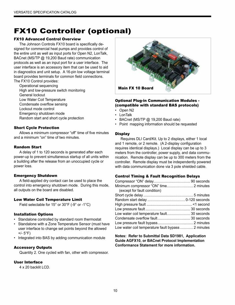
The Johnson Controls FX10 board is specifically de-signed for commercial heat pumps and provides control of the entire unit as well as input ports for Open N2, LonTalk, BACnet (MS/TP @ 19,200 Baud rate) communication protocols as well as an input port for a user interface. The user interface is an accessory item that can be used to aid in diagnostics and unit setup. A 16-pin low voltage terminal board provides terminals for common field connections. The FX10 Control provides:
Operational sequencingHigh and low-pressure switch monitoring General lockoutLow Water Coil Temperature Condensate overflow sensing Lockout mode control Emergency shutdown mode Random start and short cycle protection
Short Cycle ProtectionAllows a minimum compressor “off” time of five minutes
and a minimum “on” time of two minutes.
Random Start A delay of 1 to 120 seconds is generated after each
power-up to prevent simultaneous startup of all units within a building after the release from an unoccupied cycle or power loss.
Emergency Shutdown A field-applied dry contact can be used to place the
control into emergency shutdown mode. During this mode, all outputs on the board are disabled.
Low Water Coil Temperature Limit Field selectable for 15° or 30°F (-9° or -1°C)
Installation Options Standalone controlled by standard room thermostat• Standalone with a Zone Temperature Sensor (must have • user interface to change set points beyond the allowed +/- 5°F)Integrated into BAS by adding communication module•
Accessory Outputs Quantity 2. One cycled with fan, other with compressor.
User Interface4 x 20 backlit LCD.
Optional Plug-in Communication Modules - (compatible with standard BAS protocols)
Open N2• LonTalk• BACnet (MS/TP @ 19,200 Baud rate)• Point mapping information should be requested•
Display Requires DLI Card/Kit. Up to 2 displays, either 1 local
and 1 remote, or 2 remote. (A 2-display configuration requires identical displays.) Local display can be up to 3 meters from the controller, power supply, and data commu-nication. Remote display can be up to 300 meters from the controller. Remote display must be independently powered with data communication done via 3 pole shielded cable.
Control Timing & Fault Recognition DelaysCompressor “ON” delay.................................... 90 secondsMinimum compressor “ON” time .......................... 2 minutes (except for fault condition)Short cycle delay ................................................. 5 minutesRandom start delay ..................................... 0-120 secondsHigh pressure fault .............................................<1 secondLow pressure fault ............................................ 30 secondsLow water coil temperature fault....................... 30 secondsCondensate overflow fault ................................ 30 secondsLow pressure fault bypass ................................... 2 minutesLow water coil temperature fault bypass ............. 2 minutes
Notes: Refer to Submittal Data SD1981, Application Guide AGFX10, or BACnet Protocol Implementation Conformance Statement for more information.
Main FX 10 Board

11
VERSATEC SPECIFICATION CATALOG
Optional FX10 Microprocessor and BAS Interface
The FX10 is a microprocessor based control that not only monitors and controls the heat pump but also can communicate any of this information back to the building automation system (BAS). This means that not only does the control monitor the heat pump at the unit you can also monitor and control many the features over the BAS. This clearly puts the FX10 in a class of its own.
The control will enumerate all fault conditions (HP, LP, CO, and Low Water Coil Temp) over a BAS as well as display them on a medium user interface (MUI). HP, LP, CO and Low Water Coil Temp faults can all be reset over a BAS. A MUI is invaluable as a service tool for the building service team.
The unit can be commanded to run by a typical heat pump thermostat or run based on heating and cooling set points supplied by a BAS. The control board is wired with quick connect harnesses for easy field change out of a bad control board. An alarm history can be viewed through the MUI and will be held in memory until the unit is power cycled. Because the FX10 is not factory configured to read CO2 levels, contact the factory for application assistance.
The FX10 control has unused analog and digital inputs for field installed items such as air temperature, water tem-perature, CO2 or current status switches. The control has unused binary outputs that can be commanded over the BAS for field use.
An optional Medium User Interface (MUI) for control setup and advanced diagnostics is available with some mounting kits, MUIK1 - Panel mount version and the MUIK2-Wall mount version.
Zone SensorsThere are two options for zone sensors that can be
used with the FX10 control. Both sensors use a Johnson controls A99 positive temperature coefficient type sensor. The TAXXJ02 has a set point adjustment now which will give the end user a +/- 5°F adjustment from the set point as well as a push button that can be used for temporary occupancy. The control leaves the factory set to operate with a TAXXJ02 sensor and can be changed to read the TAXXA01 sensor through a building automation system or with a user interface.
Standard FeaturesAnti Short Cycle• High Pressure Protection• Low Pressure Protection• Loss Of Charge Detection• Random Start• Display for diagnostics•
Reset Lockout at disconnect or through BAS• 2 Accessory outputs• Optional BAS add-on controls•
DDC Operation & ConnectionOther optional network protocol boards that can be
added to the FX10 are:Johnson Control N2• LonWorks• BACnet • - MS/TP @ 19,200 Baud rate - Limit devices to 40 on a single trunk line.
Control and Safety Feature DetailsEmergency Shutdown
The emergency shutdown mode can be activated by a command from a facility management system or a closed contact on BI-2. The default state for the emergency shutdown data point is off. When the emergency shutdown mode is activated, all outputs will be turned off immediately and will remain off until the emergency shutdown mode is de-activated. The first time the compressor starts after the emergency shutdown mode has been de-activated, there will be a random start delay present.
Lockout ModeLockout mode can be activated by any of the following
fault signals: refrigerant system high pressure, refriger-ant system low pressure, low water coil temperature, and condensate overflow. When any valid fault signal remains continuously active for the length of its recognition delay, the controller will go into fault retry mode, which will turn off the compressor. After the Compressor short cycle delay, the compressor will attempt to operate once again. If three consecutive faults occur in 60 minutes during a single heat-ing or cooling demand, the unit will go into lockout mode, turning off the compressor, enabling the alarm output, and setting the fan back to low speed operation until the controller is reset. The lockout condition can be reset by powering down the controller, by a command from the BAS, or by the holding the ESC and Return keys on the MUI for 5 seconds.
Controls - FX10
12
VERSATEC SPECIFICATION CATALOG
Water Coil Temperature Limit (AI-5)The water coil low temperature limit sensor will monitor
the liquid refrigerant temperature entering the water coil in the heating mode. If the temperature drops below the water coil low temperature limit trip point for the recognition delay period, the condition will be recognized as a fault. The water coil low temperature limit trip point will be factory set for 30°F and will be field selectable for 15°F by remov-ing a jumper wire on BI-5. The water coil low temperature limit fault condition will be bypassed 2 minutes at normal compressor startup, to allow the refrigeration circuit to stabilize. If the water coil low temperature limit sensor becomes unreliable at any time compressor operation will immediately be suspended until the problem is corrected. This should be displayed as an alarm on the BAS and the MUI. This alarm will be reported a “Water Low Temp Limit” fault.
High Pressure (BI-11)The high-pressure switch shall be a normally closed
(NC) switch that monitors the systems refrigerant pressure. If the input senses the high-pressure switch is open it must disable the compressor output immediately and count the fault. The compressor minimum on time does not apply if the high-pressure switch opens. The compressor will not restart until the compressor short cycle time delay has been satisfied.
Low Pressure (BI-3)The low-pressure switch shall be a normally closed
(NC) switch that monitors the systems refrigerant pressure. If the switch is open continuously for (30) seconds during compressor operation the compressor output (BO-2) will be disabled. The compressor will not restart until the com-pressor short cycle time delay has been satisfied.
Condensate OverflowThe condensate overflow sensing circuit will monitor the
condensate level as a resistance input to AI-3. If the con-densate water level rises resulting in the input resistance rising above the set point for the recognition delay period, the condition will be recognized as a fault. The condensate will be subjected to a (30) second lockout delay which requires that the fault be sensed for a continuous (30) sec-onds before suspending unit operation.
Alarm Output (BO-6)The alarm output will be enabled when the control is in
the lockout mode and will be disabled when the lockout is reset.
Test ModeRaising the zone temperature input (AI-1) reading to
180–220°F or by holding the ESC and down arrow keys on the MUI for 5 seconds will put the control into test mode. In test mode the random start delay and the compressor fixed on delay time will both be shortened to 5 seconds and the reversing valve will be allowed to cycle with out shut-ting down the compressor. If an MUI is connected to the control LED 8 will flash and the words “Test Mode Enabled” will be shown on the LCD display when the control is in test mode. Test mode will be disabled after a power cycle, 30 minute timeout, or by holding the ESC and Up arrow keys on the MUI.
Sequence of Operation Power Fail Restart
When the controller is first powered up, the outputs will be disabled for a random start delay. The delay is provided to prevent simultaneous starting of multiple heat pumps. Once the timer expires, the controller will operate normally.
Random Start DelayThis delay will be used after every power failure, as well
as the first time the compressor is started after the control exits the unoccupied mode or the emergency shutdown mode. The delay should not be less than 1 second and not longer than 120 seconds. If the control is in test mode the random start delay will be shortened to 5 seconds.
Compressor Fixed On Delay TimeThe Compressor Fixed On Delay Time will ensure that
the compressor output (B02) is not enabled for (90) sec-onds after the control receives a call to start the compres-sor. This delay is adjustable from 30 – 300 seconds over a BAS or a MUI. If the control is in test mode the Compres-sor Fixed On Delay Timer will be shortened to 5 seconds.
Compressor Minimum On DelayThe compressor minimum on delay will ensure that the
compressor output is enabled for a minimum of (2) minute each time the compressor output is enabled. This will ap-ply in every instance except in the event the high pressure switch is tripped or emergency shutdown then the com-pressor output will be disable immediately.
Compressor Short Cycle Delay TimeThe compressor short cycle time delay will ensure that
the compressor output will not be enabled for a minimum of (5) minutes after it is disabled. This allows for the system refrigerant pressures to equalize after the compressor is disabled.
Controls - FX10 (cont.)
13
VERSATEC SPECIFICATION CATALOG
Heating CycleOn a call for heating, the blower enable output and ac-
cessory output 2 will turn on immediately after the random start delay timer has been satisfied. If the compressor short cycle time delay has been satisfied, the compressor will turn on after the blower enable and accessory output 2 are on and the fixed compressor start delay timers have been satisfied.
Set Point Control ModeIn set point control mode the reversing valve output will
be disabled. As the temperature drops below the heating set point and begins to operate in the heating proportional band, the low capacity compressor output (BO-2) will be enabled.
Thermostat Control ModeIn thermostat mode the compressor will be cycled
based on a Y1 call from a room thermostat. When the control receives a Y1 command (BI-7) from the thermostat the low capacity compressor output (BO2) will be enabled. During the heating cycle the reversing valve will be com-manded into the off position.
Cooling CycleOn a call for cooling, the blower enable output and ac-
cessory output 2 will turn on immediately after the random start delay timer has been satisfied. If the compressor short cycle time delay has been satisfied, the compressor will turn on after the blower enable and accessory output 2 are on and the fixed compressor start delay timers have been satisfied.
Set Point Control ModeIn set point control mode the reversing valve output will
be enabled. As the temperature rises above the cooling set point and begins to operate in the cooling proportional band, the compressor output (BO-2) will be enabled.
Thermostat Control ModeIn thermostat mode the compressor will be cycled
based on a Y1 call from a room thermostat. When the control receives a Y1 command (BI-7) from the thermostat the compressor output (BO2) will be enabled.
MUI Alarm History ReportingIf a fault occurs the fault will be recorded in history for
display on the medium user interface in the History Menu. Each fault type will be displayed in the history menu with a number between 0 and 3. A reading of 3+ will mean that fault has occurred more than three times in the past. The history menu can be cleared with a power cycle only. Alarm date and time are not included in the history.
Inputs & Outputs ConfigurationField Selectable Options
Water Coil Low Temperature Limit Set Point (BI-5)The water coil low temperature limit set point input al-
lows you to adjust the water coil low temperature limit set point (AI-5). When the jumper is installed on BI-5 (Wire #24) the water coil low temperature limit set point is fac-tory set for 30°F. When the jumper on BI-5 (Wire #24) is removed the water coil low temperature limit set point will be 15°F.
Accessory Outputs (BO-7 and BO-8)Accessory Output 1 will be energized 90 seconds prior
to the compressor output being energized. Accessory Out-put 2 will be energized with the fan output (BO-1). When the corresponding compressor output is turned off the accessory output will be deactivated immediately. These outputs are selectable for normally open or normally closed operation through the Medium User interface or through the Building Automation System.
Control AccessoriesZone Sensors
TAXXJ02 Room Command Module• TAXXA01 LCD Room Command Module• A99 Sensor•
MUI (LCD User interface) for diagnostics and commissioning.
MUIK1 - Panel Mount, Portable• MUIK2 - Wall Mount•
Controls - FX10 (cont.)
14
VERSATEC SPECIFICATION CATALOG
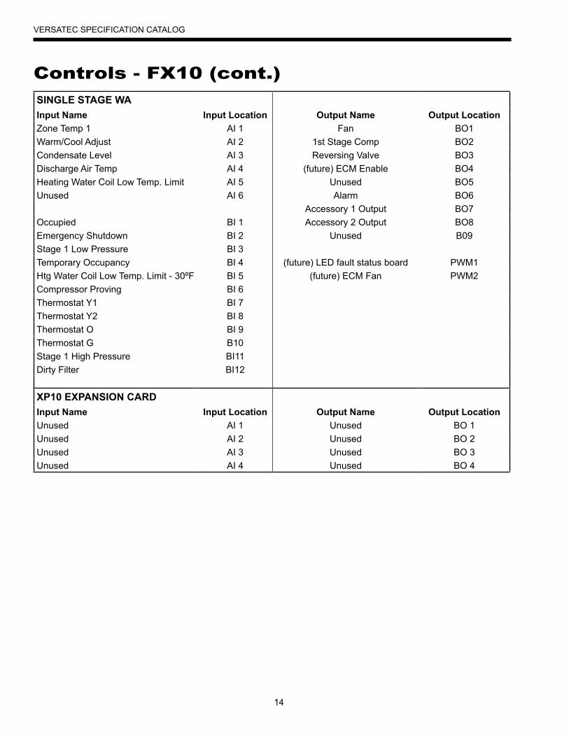
Controls - FX10 (cont.)
SINGLE STAGE WA Input Name Input Location Output Name Output LocationZone Temp 1 AI 1 Fan BO1Warm/Cool Adjust AI 2 1st Stage Comp BO2Condensate Level AI 3 Reversing Valve BO3Discharge Air Temp AI 4 (future) ECM Enable BO4Heating Water Coil Low Temp. Limit AI 5 Unused BO5Unused AI 6 Alarm BO6 Accessory 1 Output BO7Occupied BI 1 Accessory 2 Output BO8Emergency Shutdown BI 2 Unused B09Stage 1 Low Pressure BI 3 Temporary Occupancy BI 4 (future) LED fault status board PWM1Htg Water Coil Low Temp. Limit - 30ºF BI 5 (future) ECM Fan PWM2Compressor Proving BI 6 Thermostat Y1 BI 7 Thermostat Y2 BI 8 Thermostat O BI 9 Thermostat G B10 Stage 1 High Pressure BI11 Dirty Filter BI12
XP10 EXPANSION CARD Input Name Input Location Output Name Output LocationUnused AI 1 Unused BO 1Unused AI 2 Unused BO 2Unused AI 3 Unused BO 3Unused AI 4 Unused BO 4
15
VERSATEC SPECIFICATION CATALOG
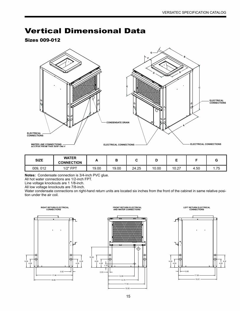
Vertical Dimensional Data
SIZE WATERCONNECTION A B C D E F G
009, 012 1/2" FPT 19.00 19.00 24.25 10.00 10.27 4.50 1.75
Notes: Condensate connection is 3/4-inch PVC glue. All hot water connections are 1/2-inch FPT. Line voltage knockouts are 1 1/8-inch. All low voltage knockouts are 7/8-inch. Water condensate connections on right-hand return units are located six inches from the front of the cabinet in same relative posi-tion under the air coil.
Sizes 009-012
ELECTRICALCONNECTIONS
ELECTRICAL CONNECTIONSWATER LINE CONNECTIONSACCESS FROM THIS SIDE ONLY
ELECTRICAL CONNECTIONS
CONDENSATE DRAIN
ELECTRICALCONNECTIONS
A
C
B
DD
E
F
G
RIGHT RETURN ELECTRICAL CONNECTIONS
FRONT RETURN ELECTRICAL AND WATER CONNECTIONS
LEFT RETURN ELECTRICAL CONNECTIONS
4.006.00
4.006.00
0.92
17.96
4.006.00
1.75
10.00
0.93
12.88
14.78
17.94
18.88
18.88
0.85
17.89
18.81
4.006.00
4.006.00
16
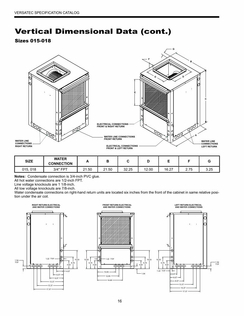
VERSATEC SPECIFICATION CATALOG
SIZE WATERCONNECTION A B C D E F G
015, 018 3/4" FPT 21.50 21.50 32.25 12.00 16.27 2.75 3.25
Vertical Dimensional Data (cont.)
Notes: Condensate connection is 3/4-inch PVC glue. All hot water connections are 1/2-inch FPT. Line voltage knockouts are 1 1/8-inch. All low voltage knockouts are 7/8-inch. Water condensate connections on right-hand return units are located six inches from the front of the cabinet in same relative posi-tion under the air coil.
Sizes 015-018
ELECTRICAL CONNECTIONSFRONT & RIGHT RETURN
ELECTRICAL CONNECTIONSFRONT & LEFT RETURN
WATER LINE CONNECTIONSFRONT RETURN
WATER LINE CONNECTIONSLEFT RETURN
WATER LINECONNECTIONSRIGHT RETURN
C
A
B
DD
G
F
E
RIGHT RETURN ELECTRICAL AND WATER CONNECTIONS
FRONT RETURN ELECTRICAL AND WATER CONNECTIONS
LEFT RETURN ELECTRICAL AND WATER CONNECTIONS
4.07
6.07
8.07
13.37
15.37
17.37
1.22 TYP
4.636.75
10.531.54TYP
4.636.75
10.53 1.22 TYP
10.65
12.65
14.65
1.54
4.636.75
10.53
1.22 TYP
4.07
6.07
8.07
13.37
15.37
17.37
1.54TYP4.63
6.75
10.53
17
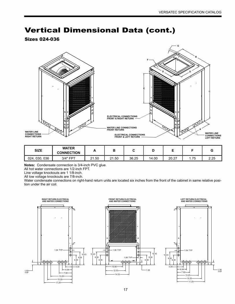
VERSATEC SPECIFICATION CATALOG
Vertical Dimensional Data (cont.)
Notes: Condensate connection is 3/4-inch PVC glue. All hot water connections are 1/2-inch FPT. Line voltage knockouts are 1 1/8-inch. All low voltage knockouts are 7/8-inch. Water condensate connections on right-hand return units are located six inches from the front of the cabinet in same relative posi-tion under the air coil.
Sizes 024-036
ELECTRICAL CONNECTIONSFRONT & RIGHT RETURN
ELECTRICAL CONNECTIONSFRONT & LEFT RETURN
WATER LINE CONNECTIONSFRONT RETURN
WATER LINECONNECTIONSLEFT RETURN
WATER LINECONNECTIONSRIGHT RETURN
DD
B
E
G
F
A
C
RIGHT RETURN ELECTRICAL AND WATER CONNECTIONS
FRONT RETURN ELECTRICAL AND WATER CONNECTIONS
LEFT RETURN ELECTRICAL AND WATER CONNECTIONS
10.66
12.53
14.53
4.046.04
7.9213.25
15.25
17.25
1.50TYP
4.046.04
7.92
17.25
13.25
15.25
1.50TYP
6.008.00
10.43
6.008.00
10.43
6.008.00
10.43
6.008.00
10.43
1.55
1.04 TYP 1.06 TYP
1.06 TYP
1.04 TYP
SIZE WATERCONNECTION A B C D E F G
024, 030, 036 3/4" FPT 21.50 21.50 36.25 14.00 20.27 1.75 2.25

18
VERSATEC SPECIFICATION CATALOG
Vertical Dimensional Data (cont.)
Notes: Condensate connection is 3/4-inch PVC glue. All hot water connections are 1/2-inch FPT. Line voltage knockouts are 1 1/8-inch. All low voltage knockouts are 7/8-inch. Water condensate connections on right-hand return units are located six inches from the front of the cabinet in same relative posi-tion under the air coil.
Sizes 042-048
ELECTRICAL CONNECTIONSFRONT & RIGHT RETURN
ELECTRICAL CONNECTIONSFRONT & LEFT RETURN
WATER LINE CONNECTIONSFRONT RETURN
WATER LINECONNECTIONSLEFT RETURN
WATER LINECONNECTIONSRIGHT RETURN
A
C
B
DD
E
F
G
RIGHT RETURN ELECTRICAL AND WATER CONNECTIONS
FRONT RETURN ELECTRICAL AND WATER CONNECTIONS
LEFT RETURN ELECTRICAL AND WATER CONNECTIONS
0.95 TYP
5.047.04
9.04
14.04
16.04
18.04
4.036.03 6.03
8.0310.03
0.95 TYP
1.50 TYP
0.95 TYP
13.74
15.74
17.74
24.88
6.038.03
10.031.50 TYP
6.038.03
10.03
0.95 TYP
3.79
5.79
7.79
12.79
14.79
16.79
1.50TYP
6.038.03
10.03
4.036.03
0.95TYP
SIZE WATERCONNECTION A B C D E F G
042, 048 3/4"(042), 1" (048) FPT 21.50 26.00 43.25 16.00 23.27 4.00 1.50
19
VERSATEC SPECIFICATION CATALOG
SIZE WATERCONNECTION A B C D E F G
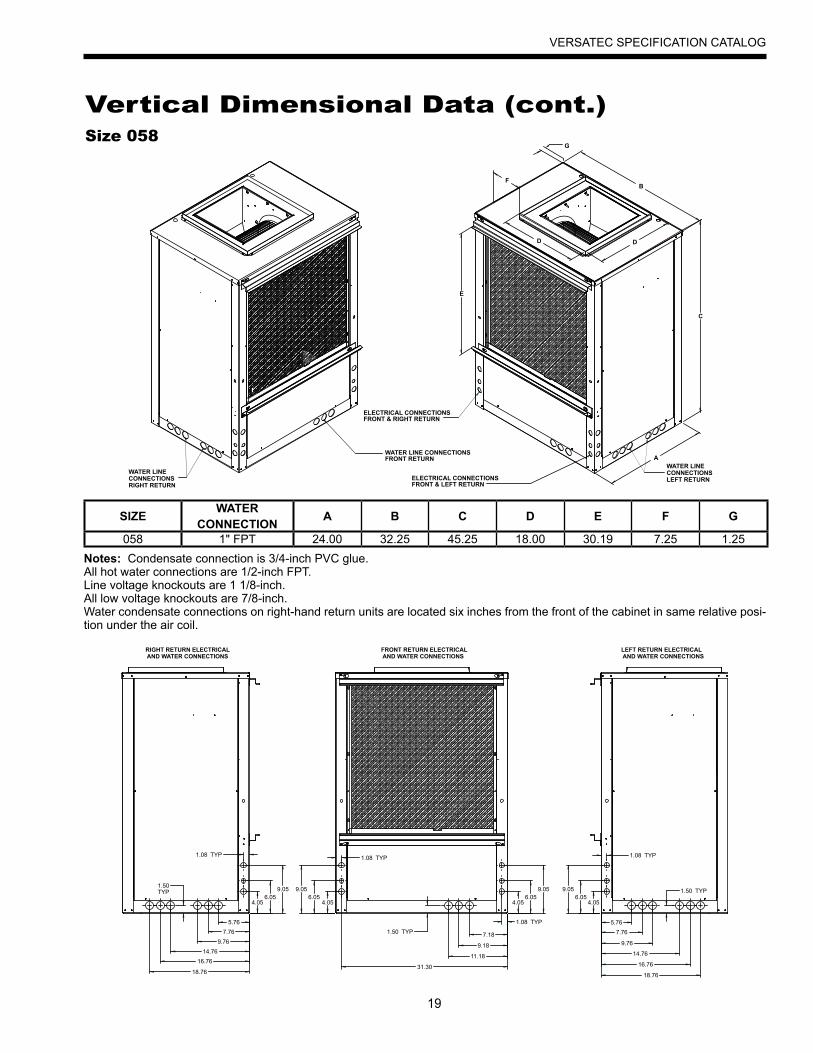
058 1" FPT 24.00 32.25 45.25 18.00 30.19 7.25 1.25
Vertical Dimensional Data (cont.)
Notes: Condensate connection is 3/4-inch PVC glue. All hot water connections are 1/2-inch FPT. Line voltage knockouts are 1 1/8-inch. All low voltage knockouts are 7/8-inch. Water condensate connections on right-hand return units are located six inches from the front of the cabinet in same relative posi-tion under the air coil.
Size 058
ELECTRICAL CONNECTIONSFRONT & RIGHT RETURN
ELECTRICAL CONNECTIONSFRONT & LEFT RETURN
WATER LINE CONNECTIONSFRONT RETURN
WATER LINECONNECTIONSLEFT RETURN
WATER LINECONNECTIONSRIGHT RETURN
A
C
B
DD
E
F
G
RIGHT RETURN ELECTRICAL AND WATER CONNECTIONS
FRONT RETURN ELECTRICAL AND WATER CONNECTIONS
LEFT RETURN ELECTRICAL AND WATER CONNECTIONS
1.50TYP
1.08 TYP
5.767.76
9.7614.76
16.76
18.76
4.056.05
9.05
4.056.05
9.05
1.08 TYP
1.08 TYP
7.18
9.18
11.18
31.30
1.50 TYP
4.056.05
9.05 1.50 TYP
4.056.05
9.05
5.767.76
14.76
16.76
18.76
1.08 TYP
9.76
20
VERSATEC SPECIFICATION CATALOG
M
L
O
K
J
I
H
NM
L
O
K
J
I
H
N
M
L
O
KJ
I
H
NM
L
O
K
J
I
H
N
Water “In”
Water “Out”
Water “In”
Water “Out”
B
C
AD
P
G
F
DE
B
C
AD
P
G
F
DE
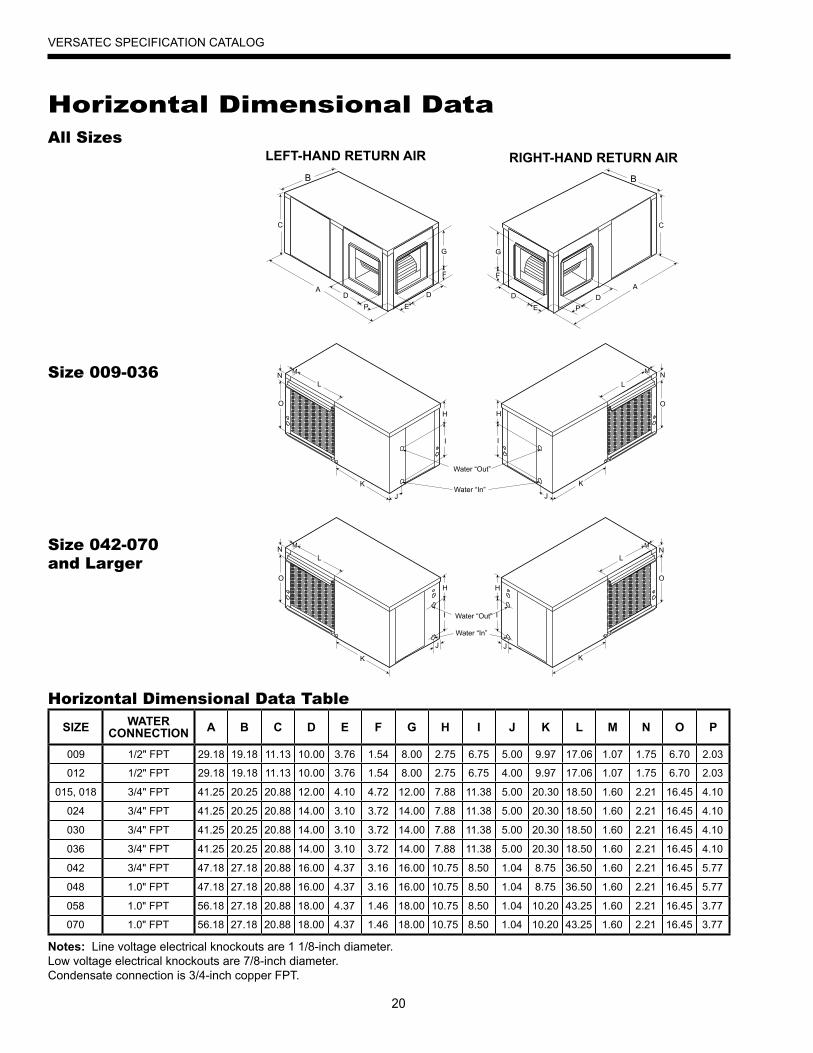
SIZE WATERCONNECTION A B C D E F G H I J K L M N O P
009 1/2" FPT 29.18 19.18 11.13 10.00 3.76 1.54 8.00 2.75 6.75 5.00 9.97 17.06 1.07 1.75 6.70 2.03
012 1/2" FPT 29.18 19.18 11.13 10.00 3.76 1.54 8.00 2.75 6.75 4.00 9.97 17.06 1.07 1.75 6.70 2.03
015, 018 3/4" FPT 41.25 20.25 20.88 12.00 4.10 4.72 12.00 7.88 11.38 5.00 20.30 18.50 1.60 2.21 16.45 4.10
024 3/4" FPT 41.25 20.25 20.88 14.00 3.10 3.72 14.00 7.88 11.38 5.00 20.30 18.50 1.60 2.21 16.45 4.10
030 3/4" FPT 41.25 20.25 20.88 14.00 3.10 3.72 14.00 7.88 11.38 5.00 20.30 18.50 1.60 2.21 16.45 4.10
036 3/4" FPT 41.25 20.25 20.88 14.00 3.10 3.72 14.00 7.88 11.38 5.00 20.30 18.50 1.60 2.21 16.45 4.10
042 3/4" FPT 47.18 27.18 20.88 16.00 4.37 3.16 16.00 10.75 8.50 1.04 8.75 36.50 1.60 2.21 16.45 5.77
048 1.0" FPT 47.18 27.18 20.88 16.00 4.37 3.16 16.00 10.75 8.50 1.04 8.75 36.50 1.60 2.21 16.45 5.77
058 1.0" FPT 56.18 27.18 20.88 18.00 4.37 1.46 18.00 10.75 8.50 1.04 10.20 43.25 1.60 2.21 16.45 3.77
070 1.0" FPT 56.18 27.18 20.88 18.00 4.37 1.46 18.00 10.75 8.50 1.04 10.20 43.25 1.60 2.21 16.45 3.77
Notes: Line voltage electrical knockouts are 1 1/8-inch diameter. Low voltage electrical knockouts are 7/8-inch diameter.Condensate connection is 3/4-inch copper FPT.
Horizontal Dimensional DataAll Sizes
Size 009-036
Size 042-070 and Larger
LEFT-HAND RETURN AIR RIGHT-HAND RETURN AIR
Horizontal Dimensional Data Table
21
VERSATEC SPECIFICATION CATALOG
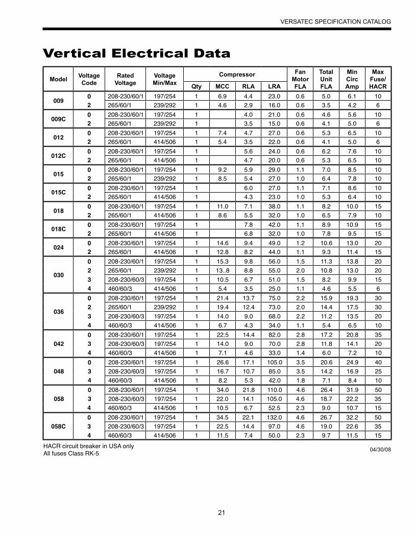
Vertical Electrical Data
Model VoltageCode
RatedVoltage
VoltageMin/Max
Compressor FanMotorFLA
TotalUnitFLA
MinCircAmp
MaxFuse/HACRQty MCC RLA LRA
009 0 208-230/60/1 197/254 1 6.9 4.4 23.0 0.6 5.0 6.1 102 265/60/1 239/292 1 4.6 2.9 16.0 0.6 3.5 4.2 6
009C 0 208-230/60/1 197/254 1 4.0 21.0 0.6 4.6 5.6 102 265/60/1 239/292 1 3.5 15.0 0.6 4.1 5.0 6
012 0 208-230/60/1 197/254 1 7.4 4.7 27.0 0.6 5.3 6.5 102 265/60/1 414/506 1 5.4 3.5 22.0 0.6 4.1 5.0 6
012C 0 208-230/60/1 197/254 1 5.6 24.0 0.6 6.2 7.6 102 265/60/1 414/506 1 4.7 20.0 0.6 5.3 6.5 10
015 0 208-230/60/1 197/254 1 9.2 5.9 29.0 1.1 7.0 8.5 102 265/60/1 239/292 1 8.5 5.4 27.0 1.0 6.4 7.8 10
015C 0 208-230/60/1 197/254 1 6.0 27.0 1.1 7.1 8.6 102 265/60/1 414/506 1 4.3 23.0 1.0 5.3 6.4 10
018 0 208-230/60/1 197/254 1 11.0 7.1 38.0 1.1 8.2 10.0 152 265/60/1 414/506 1 8.6 5.5 32.0 1.0 6.5 7.9 10
018C 0 208-230/60/1 197/254 1 7.8 42.0 1.1 8.9 10.9 152 265/60/1 414/506 1 6.8 32.0 1.0 7.8 9.5 15
024 0 208-230/60/1 197/254 1 14.6 9.4 49.0 1.2 10.6 13.0 202 265/60/1 414/506 1 12.8 8.2 44.0 1.1 9.3 11.4 15
030
0 208-230/60/1 197/254 1 15.3 9.8 56.0 1.5 11.3 13.8 202 265/60/1 239/292 1 13..8 8.8 55.0 2.0 10.8 13.0 203 208-230/60/3 197/254 1 10.5 6.7 51.0 1.5 8.2 9.9 154 460/60/3 414/506 1 5.4 3.5 25.0 1.1 4.6 5.5 6
036
0 208-230/60/1 197/254 1 21.4 13.7 75.0 2.2 15.9 19.3 302 265/60/1 239/292 1 19.4 12.4 73.0 2.0 14.4 17.5 303 208-230/60/3 197/254 1 14.0 9.0 68.0 2.2 11.2 13.5 204 460/60/3 414/506 1 6.7 4.3 34.0 1.1 5.4 6.5 10
0420 208-230/60/1 197/254 1 22.5 14.4 82.0 2.8 17.2 20.8 353 208-230/60/3 197/254 1 14.0 9.0 70.0 2.8 11.8 14.1 204 460/60/3 414/506 1 7.1 4.6 33.0 1.4 6.0 7.2 10
0480 208-230/60/1 197/254 1 26.6 17.1 105.0 3.5 20.6 24.9 403 208-230/60/3 197/254 1 16.7 10.7 85.0 3.5 14.2 16.9 254 460/60/3 414/506 1 8.2 5.3 42.0 1.8 7.1 8.4 10
0580 208-230/60/1 197/254 1 34.0 21.8 110.0 4.6 26.4 31.9 503 208-230/60/3 197/254 1 22.0 14.1 105.0 4.6 18.7 22.2 354 460/60/3 414/506 1 10.5 6.7 52.5 2.3 9.0 10.7 15
058C0 208-230/60/1 197/254 1 34.5 22.1 132.0 4.6 26.7 32.2 503 208-230/60/3 197/254 1 22.5 14.4 97.0 4.6 19.0 22.6 354 460/60/3 414/506 1 11.5 7.4 50.0 2.3 9.7 11.5 15
HACR circuit breaker in USA only All fuses Class RK-5 04/30/08
22
VERSATEC SPECIFICATION CATALOG
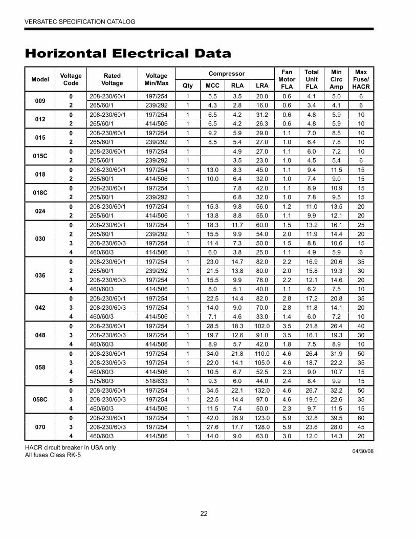
Horizontal Electrical Data
Model VoltageCode
RatedVoltage
VoltageMin/Max
Compressor FanMotorFLA
TotalUnitFLA
MinCircAmp
MaxFuse/HACRQty MCC RLA LRA
0090 208-230/60/1 197/254 1 5.5 3.5 20.0 0.6 4.1 5.0 62 265/60/1 239/292 1 4.3 2.8 16.0 0.6 3.4 4.1 6
0120 208-230/60/1 197/254 1 6.5 4.2 31.2 0.6 4.8 5.9 102 265/60/1 414/506 1 6.5 4.2 26.3 0.6 4.8 5.9 10
0150 208-230/60/1 197/254 1 9.2 5.9 29.0 1.1 7.0 8.5 102 265/60/1 239/292 1 8.5 5.4 27.0 1.0 6.4 7.8 10
015C0 208-230/60/1 197/254 1 4.9 27.0 1.1 6.0 7.2 102 265/60/1 239/292 1 3.5 23.0 1.0 4.5 5.4 6
0180 208-230/60/1 197/254 1 13.0 8.3 45.0 1.1 9.4 11.5 152 265/60/1 414/506 1 10.0 6.4 32.0 1.0 7.4 9.0 15
018C0 208-230/60/1 197/254 1 7.8 42.0 1.1 8.9 10.9 152 265/60/1 239/292 1 6.8 32.0 1.0 7.8 9.5 15
0240 208-230/60/1 197/254 1 15.3 9.8 56.0 1.2 11.0 13.5 202 265/60/1 414/506 1 13.8 8.8 55.0 1.1 9.9 12.1 20
030
0 208-230/60/1 197/254 1 18.3 11.7 60.0 1.5 13.2 16.1 252 265/60/1 239/292 1 15.5 9.9 54.0 2.0 11.9 14.4 203 208-230/60/3 197/254 1 11.4 7.3 50.0 1.5 8.8 10.6 154 460/60/3 414/506 1 6.0 3.8 25.0 1.1 4.9 5.9 6
036
0 208-230/60/1 197/254 1 23.0 14.7 82.0 2.2 16.9 20.6 352 265/60/1 239/292 1 21.5 13.8 80.0 2.0 15.8 19.3 303 208-230/60/3 197/254 1 15.5 9.9 78.0 2.2 12.1 14.6 204 460/60/3 414/506 1 8.0 5.1 40.0 1.1 6.2 7.5 10
0420 208-230/60/1 197/254 1 22.5 14.4 82.0 2.8 17.2 20.8 353 208-230/60/3 197/254 1 14.0 9.0 70.0 2.8 11.8 14.1 204 460/60/3 414/506 1 7.1 4.6 33.0 1.4 6.0 7.2 10
0480 208-230/60/1 197/254 1 28.5 18.3 102.0 3.5 21.8 26.4 403 208-230/60/3 197/254 1 19.7 12.6 91.0 3.5 16.1 19.3 304 460/60/3 414/506 1 8.9 5.7 42.0 1.8 7.5 8.9 10
058
0 208-230/60/1 197/254 1 34.0 21.8 110.0 4.6 26.4 31.9 503 208-230/60/3 197/254 1 22.0 14.1 105.0 4.6 18.7 22.2 354 460/60/3 414/506 1 10.5 6.7 52.5 2.3 9.0 10.7 155 575/60/3 518/633 1 9.3 6.0 44.0 2.4 8.4 9.9 15
058C0 208-230/60/1 197/254 1 34.5 22.1 132.0 4.6 26.7 32.2 503 208-230/60/3 197/254 1 22.5 14.4 97.0 4.6 19.0 22.6 354 460/60/3 414/506 1 11.5 7.4 50.0 2.3 9.7 11.5 15
0700 208-230/60/1 197/254 1 42.0 26.9 123.0 5.9 32.8 39.5 603 208-230/60/3 197/254 1 27.6 17.7 128.0 5.9 23.6 28.0 454 460/60/3 414/506 1 14.0 9.0 63.0 3.0 12.0 14.3 20
HACR circuit breaker in USA only All fuses Class RK-5 04/30/08
23
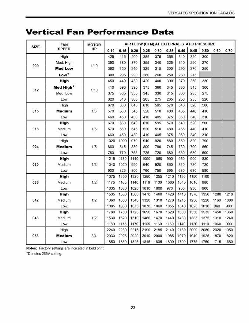
VERSATEC SPECIFICATION CATALOG
SIZE FANSPEED
MOTOR HP
AIR FLOW (CFM) AT EXTERNAL STATIC PRESSURE
0.10 0.15 0.20 0.25 0.30 0.35 0.40 0.45 0.50 0.60 0.70
009
High
1/10
425 415 400 385 375 355 340 320 300Med. High 390 380 370 355 340 325 310 290 270Med Low 360 350 340 325 315 300 290 270 250
Low* 300 295 290 280 260 250 230 215
012
High
1/10
450 440 430 420 400 390 370 350 330
Med High* 410 395 390 375 360 345 330 315 300Med. Low 375 365 355 345 330 315 300 285 275
Low 320 310 300 285 275 265 250 235 220
015High
1/6670 660 640 610 595 570 540 520 500
Medium 570 560 545 520 510 480 465 440 410Low 460 450 430 410 405 375 360 340 310
018High
1/6670 660 640 610 595 570 540 520 500
Medium 570 560 545 520 510 480 465 440 410Low 460 450 430 410 405 375 360 340 310
024High
1/51020 1000 970 940 920 880 850 820 790
Medium 860 845 830 800 780 745 730 700 660Low 780 770 755 725 720 680 660 630 600
030High
1/31215 1180 1140 1090 1060 990 950 900 830
Medium 1040 1020 990 940 920 860 830 780 720Low 930 825 800 760 750 695 680 630 580
036High
1/21375 1350 1320 1280 1255 1210 1180 1150 1100
Medium 1175 1160 1140 1110 1100 1060 1040 1010 980Low 1035 1030 1020 1010 1000 970 960 930 900
042High
1/21535 1530 1500 1470 1460 1420 1410 1370 1350 1280 1210
Medium 1360 1350 1340 1320 1310 1270 1245 1230 1220 1160 1080Low 1085 1080 1075 1070 1060 1055 1040 1025 1010 960 900
048High
1/21780 1760 1725 1690 1670 1620 1600 1550 1535 1450 1360
Medium 1530 1520 1510 1480 1470 1440 1430 1385 1375 1310 1240Low 1180 1175 1170 1165 1160 1150 1140 1120 1110 1060 990
058High
3/42240 2230 2215 2190 2185 2140 2130 2090 2080 2020 1950
Medium 2030 2025 2020 2010 2000 1985 1970 1940 1925 1870 1820Low 1850 1830 1825 1815 1805 1800 1790 1775 1750 1715 1660
Vertical Fan Performance Data
Notes: Factory settings are indicated in bold print.*Denotes 265V setting.
24
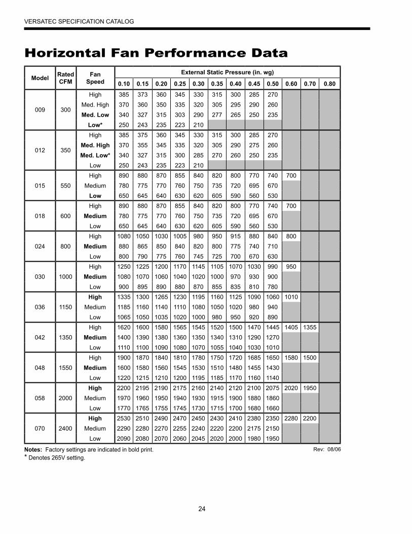
VERSATEC SPECIFICATION CATALOG
Model RatedCFM
FanSpeed
External Static Pressure (in. wg)
0.10 0.15 0.20 0.25 0.30 0.35 0.40 0.45 0.50 0.60 0.70 0.80
009 300
High 385 373 360 345 330 315 300 285 270
Med. High 370 360 350 335 320 305 295 290 260
Med. Low 340 327 315 303 290 277 265 250 235
Low* 250 243 235 223 210
012 350
High 385 375 360 345 330 315 300 285 270
Med. High 370 355 345 335 320 305 290 275 260
Med. Low* 340 327 315 300 285 270 260 250 235
Low 250 243 235 223 210
015 550
High 890 880 870 855 840 820 800 770 740 700
Medium 780 775 770 760 750 735 720 695 670
Low 650 645 640 630 620 605 590 560 530
018 600
High 890 880 870 855 840 820 800 770 740 700
Medium 780 775 770 760 750 735 720 695 670
Low 650 645 640 630 620 605 590 560 530
024 800
High 1080 1050 1030 1005 980 950 915 880 840 800
Medium 880 865 850 840 820 800 775 740 710
Low 800 790 775 760 745 725 700 670 630
030 1000
High 1250 1225 1200 1170 1145 1105 1070 1030 990 950
Medium 1080 1070 1060 1040 1020 1000 970 930 900
Low 900 895 890 880 870 855 835 810 780
036 1150
High 1335 1300 1265 1230 1195 1160 1125 1090 1060 1010
Medium 1185 1160 1140 1110 1080 1050 1020 980 940
Low 1065 1050 1035 1020 1000 980 950 920 890
042 1350
High 1620 1600 1580 1565 1545 1520 1500 1470 1445 1405 1355
Medium 1400 1390 1380 1360 1350 1340 1310 1290 1270
Low 1110 1100 1090 1080 1070 1055 1040 1030 1010
048 1550
High 1900 1870 1840 1810 1780 1750 1720 1685 1650 1580 1500
Medium 1600 1580 1560 1545 1530 1510 1480 1455 1430
Low 1220 1215 1210 1200 1195 1185 1170 1160 1140
058 2000
High 2200 2195 2190 2175 2160 2140 2120 2100 2075 2020 1950
Medium 1970 1960 1950 1940 1930 1915 1900 1880 1860
Low 1770 1765 1755 1745 1730 1715 1700 1680 1660
070 2400
High 2530 2510 2490 2470 2450 2430 2410 2380 2350 2280 2200
Medium 2290 2280 2270 2255 2240 2220 2200 2175 2150
Low 2090 2080 2070 2060 2045 2020 2000 1980 1950
Horizontal Fan Performance Data
Notes: Factory settings are indicated in bold print.* Denotes 265V setting.
Rev: 08/06
25
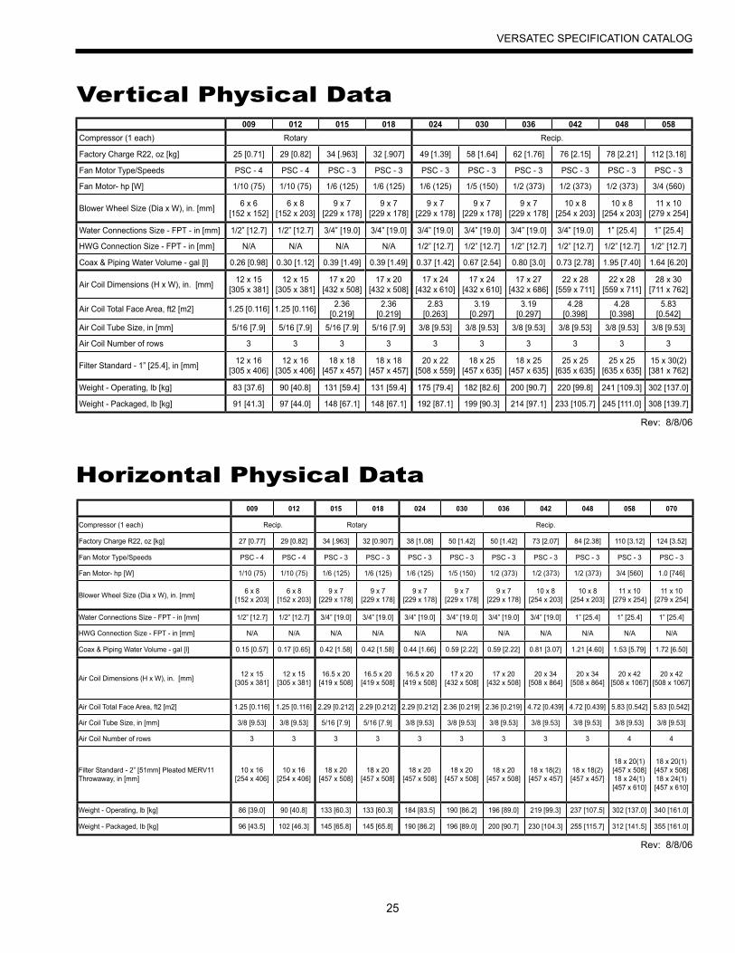
VERSATEC SPECIFICATION CATALOG
009 012 015 018 024 030 036 042 048 058Compressor (1 each) Rotary Recip.
Factory Charge R22, oz [kg] 25 [0.71] 29 [0.82] 34 [.963] 32 [.907] 49 [1.39] 58 [1.64] 62 [1.76] 76 [2.15] 78 [2.21] 112 [3.18]
Fan Motor Type/Speeds PSC - 4 PSC - 4 PSC - 3 PSC - 3 PSC - 3 PSC - 3 PSC - 3 PSC - 3 PSC - 3 PSC - 3
Fan Motor- hp [W] 1/10 (75) 1/10 (75) 1/6 (125) 1/6 (125) 1/6 (125) 1/5 (150) 1/2 (373) 1/2 (373) 1/2 (373) 3/4 (560)
Blower Wheel Size (Dia x W), in. [mm] 6 x 6[152 x 152]
6 x 8 [152 x 203]
9 x 7 [229 x 178]
9 x 7 [229 x 178]
9 x 7 [229 x 178]
9 x 7 [229 x 178]
9 x 7 [229 x 178]
10 x 8 [254 x 203]
10 x 8 [254 x 203]
11 x 10 [279 x 254]
Water Connections Size - FPT - in [mm] 1/2” [12.7] 1/2” [12.7] 3/4” [19.0] 3/4” [19.0] 3/4” [19.0] 3/4” [19.0] 3/4” [19.0] 3/4” [19.0] 1” [25.4] 1” [25.4]
HWG Connection Size - FPT - in [mm] N/A N/A N/A N/A 1/2” [12.7] 1/2” [12.7] 1/2” [12.7] 1/2” [12.7] 1/2” [12.7] 1/2” [12.7]
Coax & Piping Water Volume - gal [l] 0.26 [0.98] 0.30 [1.12] 0.39 [1.49] 0.39 [1.49] 0.37 [1.42] 0.67 [2.54] 0.80 [3.0] 0.73 [2.78] 1.95 [7.40] 1.64 [6.20]
Air Coil Dimensions (H x W), in. [mm] 12 x 15 [305 x 381]
12 x 15 [305 x 381]
17 x 20 [432 x 508]
17 x 20 [432 x 508]
17 x 24 [432 x 610]
17 x 24 [432 x 610]
17 x 27 [432 x 686]
22 x 28 [559 x 711]
22 x 28 [559 x 711]
28 x 30 [711 x 762]
Air Coil Total Face Area, ft2 [m2] 1.25 [0.116] 1.25 [0.116] 2.36 [0.219]
2.36 [0.219]
2.83 [0.263]
3.19 [0.297]
3.19 [0.297]
4.28 [0.398]
4.28 [0.398]
5.83 [0.542]
Air Coil Tube Size, in [mm] 5/16 [7.9] 5/16 [7.9] 5/16 [7.9] 5/16 [7.9] 3/8 [9.53] 3/8 [9.53] 3/8 [9.53] 3/8 [9.53] 3/8 [9.53] 3/8 [9.53]
Air Coil Number of rows 3 3 3 3 3 3 3 3 3 3
Filter Standard - 1” [25.4], in [mm] 12 x 16 [305 x 406]
12 x 16 [305 x 406]
18 x 18 [457 x 457]
18 x 18 [457 x 457]
20 x 22 [508 x 559]
18 x 25 [457 x 635]
18 x 25 [457 x 635]
25 x 25 [635 x 635]
25 x 25 [635 x 635]
15 x 30(2) [381 x 762]
Weight - Operating, lb [kg] 83 [37.6] 90 [40.8] 131 [59.4] 131 [59.4] 175 [79.4] 182 [82.6] 200 [90.7] 220 [99.8] 241 [109.3] 302 [137.0]
Weight - Packaged, lb [kg] 91 [41.3] 97 [44.0] 148 [67.1] 148 [67.1] 192 [87.1] 199 [90.3] 214 [97.1] 233 [105.7] 245 [111.0] 308 [139.7]
Vertical Physical Data
009 012 015 018 024 030 036 042 048 058 070
Compressor (1 each) Recip. Rotary Recip.
Factory Charge R22, oz [kg] 27 [0.77] 29 [0.82] 34 [.963] 32 [0.907] 38 [1.08] 50 [1.42] 50 [1.42] 73 [2.07] 84 [2.38] 110 [3.12] 124 [3.52]
Fan Motor Type/Speeds PSC - 4 PSC - 4 PSC - 3 PSC - 3 PSC - 3 PSC - 3 PSC - 3 PSC - 3 PSC - 3 PSC - 3 PSC - 3
Fan Motor- hp [W] 1/10 (75) 1/10 (75) 1/6 (125) 1/6 (125) 1/6 (125) 1/5 (150) 1/2 (373) 1/2 (373) 1/2 (373) 3/4 [560] 1.0 [746]
Blower Wheel Size (Dia x W), in. [mm] 6 x 8[152 x 203]
6 x 8 [152 x 203]
9 x 7 [229 x 178]
9 x 7 [229 x 178]
9 x 7 [229 x 178]
9 x 7 [229 x 178]
9 x 7 [229 x 178]
10 x 8 [254 x 203]
10 x 8 [254 x 203]
11 x 10 [279 x 254]
11 x 10 [279 x 254]
Water Connections Size - FPT - in [mm] 1/2” [12.7] 1/2” [12.7] 3/4” [19.0] 3/4” [19.0] 3/4” [19.0] 3/4” [19.0] 3/4” [19.0] 3/4” [19.0] 1” [25.4] 1” [25.4] 1” [25.4]
HWG Connection Size - FPT - in [mm] N/A N/A N/A N/A N/A N/A N/A N/A N/A N/A N/A
Coax & Piping Water Volume - gal [l] 0.15 [0.57] 0.17 [0.65] 0.42 [1.58] 0.42 [1.58] 0.44 [1.66] 0.59 [2.22] 0.59 [2.22] 0.81 [3.07] 1.21 [4.60] 1.53 [5.79] 1.72 [6.50]
Air Coil Dimensions (H x W), in. [mm] 12 x 15 [305 x 381]
12 x 15 [305 x 381]
16.5 x 20 [419 x 508]
16.5 x 20 [419 x 508]
16.5 x 20 [419 x 508]
17 x 20 [432 x 508]
17 x 20 [432 x 508]
20 x 34 [508 x 864]
20 x 34 [508 x 864]
20 x 42 [508 x 1067]
20 x 42 [508 x 1067]
Air Coil Total Face Area, ft2 [m2] 1.25 [0.116] 1.25 [0.116] 2.29 [0.212] 2.29 [0.212] 2.29 [0.212] 2.36 [0.219] 2.36 [0.219] 4.72 [0.439] 4.72 [0.439] 5.83 [0.542] 5.83 [0.542]
Air Coil Tube Size, in [mm] 3/8 [9.53] 3/8 [9.53] 5/16 [7.9] 5/16 [7.9] 3/8 [9.53] 3/8 [9.53] 3/8 [9.53] 3/8 [9.53] 3/8 [9.53] 3/8 [9.53] 3/8 [9.53]
Air Coil Number of rows 3 3 3 3 3 3 3 3 3 4 4
Filter Standard - 2” [51mm] Pleated MERV11 Throwaway, in [mm]
10 x 16 [254 x 406]
10 x 16 [254 x 406]
18 x 20 [457 x 508]
18 x 20 [457 x 508]
18 x 20 [457 x 508]
18 x 20 [457 x 508]
18 x 20 [457 x 508]
18 x 18(2) [457 x 457]
18 x 18(2) [457 x 457]
18 x 20(1) [457 x 508] 18 x 24(1) [457 x 610]
18 x 20(1) [457 x 508] 18 x 24(1) [457 x 610]
Weight - Operating, lb [kg] 86 [39.0] 90 [40.8] 133 [60.3] 133 [60.3] 184 [83.5] 190 [86.2] 196 [89.0] 219 [99.3] 237 [107.5] 302 [137.0] 340 [161.0]
Weight - Packaged, lb [kg] 96 [43.5] 102 [46.3] 145 [65.8] 145 [65.8] 190 [86.2] 196 [89.0] 200 [90.7] 230 [104.3] 255 [115.7] 312 [141.5] 355 [161.0]
Horizontal Physical Data
Rev: 8/8/06
Rev: 8/8/06
26
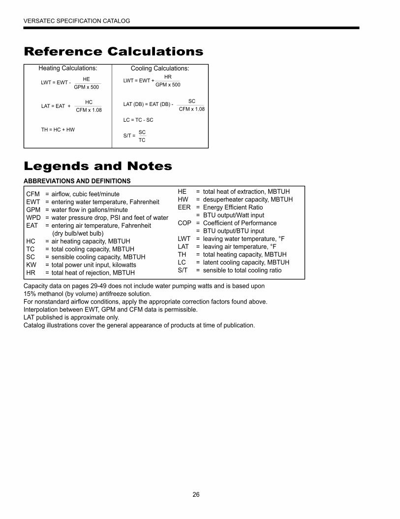
VERSATEC SPECIFICATION CATALOG
Reference CalculationsHeating Calculations: Cooling Calculations:
LWT = EWT +
LAT (DB) = EAT (DB) -
LC = TC - SC
S/T =
HRGPM x 500
SCCFM x 1.08
SCTC
LWT = EWT -
LAT = EAT +
TH = HC + HW
HEGPM x 500
HCCFM x 1.08
Legends and Notes
Capacity data on pages 29-49 does not include water pumping watts and is based upon 15% methanol (by volume) antifreeze solution.For nonstandard airflow conditions, apply the appropriate correction factors found above.Interpolation between EWT, GPM and CFM data is permissible.LAT published is approximate only.Catalog illustrations cover the general appearance of products at time of publication.
CFM = airflow, cubic feet/minuteEWT = entering water temperature, FahrenheitGPM = water flow in gallons/minuteWPD = water pressure drop, PSI and feet of waterEAT = entering air temperature, Fahrenheit (dry bulb/wet bulb)HC = air heating capacity, MBTUHTC = total cooling capacity, MBTUHSC = sensible cooling capacity, MBTUHKW = total power unit input, kilowattsHR = total heat of rejection, MBTUH
HE = total heat of extraction, MBTUHHW = desuperheater capacity, MBTUHEER = Energy Efficient Ratio = BTU output/Watt inputCOP = Coefficient of Performance = BTU output/BTU inputLWT = leaving water temperature, °FLAT = leaving air temperature, °FTH = total heating capacity, MBTUHLC = latent cooling capacity, MBTUHS/T = sensible to total cooling ratio
ABBREVIATIONS AND DEFINITIONS
27
VERSATEC SPECIFICATION CATALOG
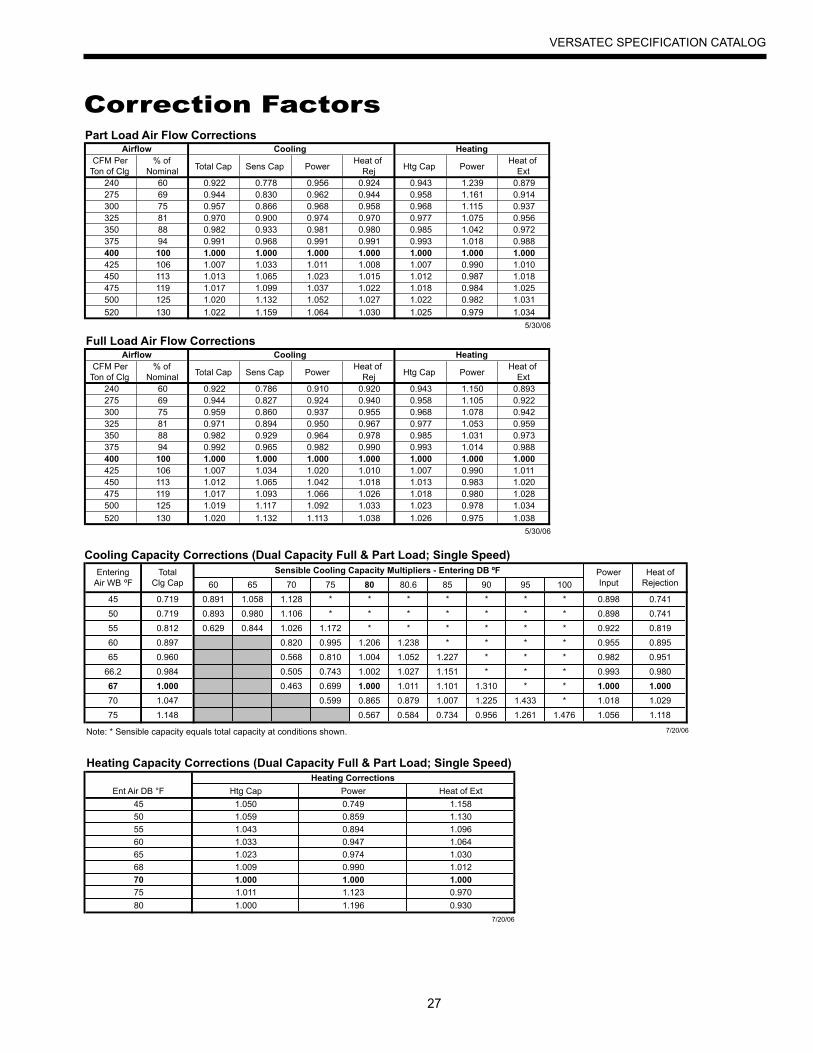
Part Load Air Flow Corrections
Full Load Air Flow Corrections
CoolingCFM Per
Ton of Clg% of
Nominal Total Cap Sens Cap PowerHeat of
Rej Htg Cap PowerHeat of
Ext240 60 0.922 0.778 0.956 0.924 0.943 1.239 0.879275 69 0.944 0.830 0.962 0.944 0.958 1.161 0.914300 75 0.957 0.866 0.968 0.958 0.968 1.115 0.937325 81 0.970 0.900 0.974 0.970 0.977 1.075 0.956350 88 0.982 0.933 0.981 0.980 0.985 1.042 0.972375 94 0.991 0.968 0.991 0.991 0.993 1.018 0.988400 100 1.000 1.000 1.000 1.000 1.000 1.000 1.000425 106 1.007 1.033 1.011 1.008 1.007 0.990 1.010450 113 1.013 1.065 1.023 1.015 1.012 0.987 1.018475 119 1.017 1.099 1.037 1.022 1.018 0.984 1.025500 125 1.020 1.132 1.052 1.027 1.022 0.982 1.031
520 130 1.022 1.159 1.064 1.030 1.025 0.979 1.034
5/30/06
CoolingCFM Per
Ton of Clg% of
Nominal Total Cap Sens Cap PowerHeat of
Rej Htg Cap PowerHeat of
Ext240 60 0.922 0.786 0.910 0.920 0.943 1.150 0.893275 69 0.944 0.827 0.924 0.940 0.958 1.105 0.922300 75 0.959 0.860 0.937 0.955 0.968 1.078 0.942325 81 0.971 0.894 0.950 0.967 0.977 1.053 0.959350 88 0.982 0.929 0.964 0.978 0.985 1.031 0.973375 94 0.992 0.965 0.982 0.990 0.993 1.014 0.988400 100 1.000 1.000 1.000 1.000 1.000 1.000 1.000425 106 1.007 1.034 1.020 1.010 1.007 0.990 1.011450 113 1.012 1.065 1.042 1.018 1.013 0.983 1.020475 119 1.017 1.093 1.066 1.026 1.018 0.980 1.028500 125 1.019 1.117 1.092 1.033 1.023 0.978 1.034
520 130 1.020 1.132 1.113 1.038 1.026 0.975 1.038
5/30/06
Airflow Heating
Airflow Heating
Heating Capacity Corrections (Dual Capacity Full & Part Load; Single Speed)Heating Corrections
Ent Air DB °F Htg Cap Power Heat of Ext
45 1.050 0.749 1.158
50 1.059 0.859 1.130
55 1.043 0.894 1.096
60 1.033 0.947 1.064
65 1.023 0.974 1.030
68 1.009 0.990 1.012
70 1.000 1.000 1.000
75 1.011 1.123 0.970
80 1.000 1.196 0.930
7/20/06
Cooling Capacity Corrections (Dual Capacity Full & Part Load; Single Speed)Entering Total Sensible Cooling Capacity Multipliers - Entering DB ºF Power Heat of
Air WB ºF Clg Cap 60 65 70 75 80 80.6 85 90 95 100 Input Rejection
45 0.719 0.891 1.058 1.128 * * * * * * * 0.898 0.741
50 0.719 0.893 0.980 1.106 * * * * * * * 0.898 0.741
55 0.812 0.629 0.844 1.026 1.172 * * * * * * 0.922 0.819
60 0.897 0.820 0.995 1.206 1.238 * * * * 0.955 0.895
65 0.960 0.568 0.810 1.004 1.052 1.227 * * * 0.982 0.951
66.2 0.984 0.505 0.743 1.002 1.027 1.151 * * * 0.993 0.980
67 1.000 0.463 0.699 1.000 1.011 1.101 1.310 * * 1.000 1.000
70 1.047 0.599 0.865 0.879 1.007 1.225 1.433 * 1.018 1.029
75 1.148 0.567 0.584 0.734 0.956 1.261 1.476 1.056 1.118
Note: * Sensible capacity equals total capacity at conditions shown. 7/20/06
Correction Factors
28
VERSATEC SPECIFICATION CATALOG
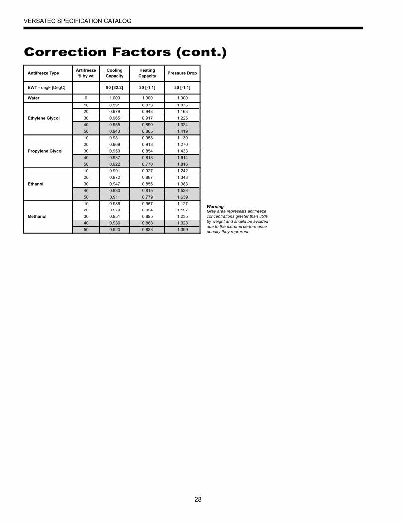
Antifreeze TypeAntifreeze% by wt
Cooling Capacity
Heating Capacity
Pressure Drop
EWT - degF [DegC] 90 [32.2] 30 [-1.1] 30 [-1.1]
Water 0 1.000 1.000 1.000
10 0.991 0.973 1.075
20 0.979 0.943 1.163
Ethylene Glycol 30 0.965 0.917 1.225
40 0.955 0.890 1.324
50 0.943 0.865 1.419
10 0.981 0.958 1.130
20 0.969 0.913 1.270
Propylene Glycol 30 0.950 0.854 1.433
40 0.937 0.813 1.614
50 0.922 0.770 1.816
10 0.991 0.927 1.242
20 0.972 0.887 1.343
Ethanol 30 0.947 0.856 1.383
40 0.930 0.815 1.523
50 0.911 0.779 1.639
10 0.986 0.957 1.127
20 0.970 0.924 1.197
Methanol 30 0.951 0.895 1.235
40 0.936 0.863 1.323
50 0.920 0.833 1.399
Warning:Gray area represents antifreeze concentrations greater than 35% by weight and should be avoided due to the extreme performance penalty they represent.
Correction Factors (cont.)
29
VERSATEC SPECIFICATION CATALOG
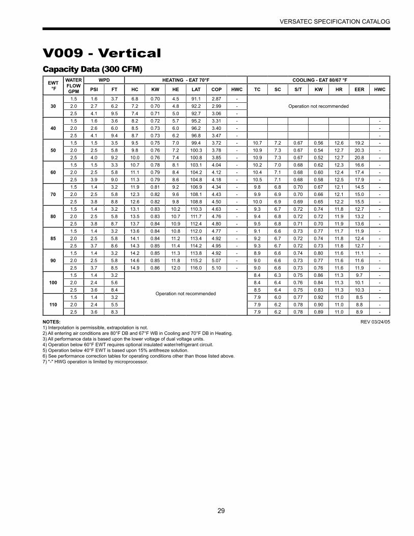
V009 - VerticalCapacity Data (300 CFM)
EWT °F
WATER FLOWGPM
WPD HEATING - EAT 70°F COOLING - EAT 80/67 °F
PSI FT HC KW HE LAT COP HWC TC SC S/T KW HR EER HWC
301.5 1.6 3.7 6.8 0.70 4.5 91.1 2.87 -
Operation not recommended2.0 2.7 6.2 7.2 0.70 4.8 92.2 2.99 -2.5 4.1 9.5 7.4 0.71 5.0 92.7 3.06 -
401.5 1.6 3.6 8.2 0.72 5.7 95.2 3.31 - -2.0 2.6 6.0 8.5 0.73 6.0 96.2 3.40 - -2.5 4.1 9.4 8.7 0.73 6.2 96.8 3.47 - -
501.5 1.5 3.5 9.5 0.75 7.0 99.4 3.72 - 10.7 7.2 0.67 0.56 12.6 19.2 -2.0 2.5 5.8 9.8 0.76 7.2 100.3 3.78 - 10.9 7.3 0.67 0.54 12.7 20.3 -2.5 4.0 9.2 10.0 0.76 7.4 100.8 3.85 - 10.9 7.3 0.67 0.52 12.7 20.8 -
601.5 1.5 3.3 10.7 0.78 8.1 103.1 4.04 - 10.2 7.0 0.68 0.62 12.3 16.6 -2.0 2.5 5.8 11.1 0.79 8.4 104.2 4.12 - 10.4 7.1 0.68 0.60 12.4 17.4 -2.5 3.9 9.0 11.3 0.79 8.6 104.8 4.18 - 10.5 7.1 0.68 0.58 12.5 17.9 -
701.5 1.4 3.2 11.9 0.81 9.2 106.9 4.34 - 9.8 6.8 0.70 0.67 12.1 14.5 -2.0 2.5 5.8 12.3 0.82 9.6 108.1 4.43 - 9.9 6.9 0.70 0.66 12.1 15.0 -2.5 3.8 8.8 12.6 0.82 9.8 108.8 4.50 - 10.0 6.9 0.69 0.65 12.2 15.5 -
801.5 1.4 3.2 13.1 0.83 10.2 110.3 4.63 - 9.3 6.7 0.72 0.74 11.8 12.7 -2.0 2.5 5.8 13.5 0.83 10.7 111.7 4.76 - 9.4 6.8 0.72 0.72 11.9 13.2 -2.5 3.8 8.7 13.7 0.84 10.9 112.4 4.80 - 9.5 6.8 0.71 0.70 11.9 13.6 -
851.5 1.4 3.2 13.6 0.84 10.8 112.0 4.77 - 9.1 6.6 0.73 0.77 11.7 11.9 -2.0 2.5 5.8 14.1 0.84 11.2 113.4 4.92 - 9.2 6.7 0.72 0.74 11.8 12.4 -2.5 3.7 8.6 14.3 0.85 11.4 114.2 4.95 - 9.3 6.7 0.72 0.73 11.8 12.7 -
901.5 1.4 3.2 14.2 0.85 11.3 113.8 4.92 - 8.9 6.6 0.74 0.80 11.6 11.1 -2.0 2.5 5.8 14.6 0.85 11.8 115.2 5.07 - 9.0 6.6 0.73 0.77 11.6 11.6 -2.5 3.7 8.5 14.9 0.86 12.0 116.0 5.10 - 9.0 6.6 0.73 0.76 11.6 11.9 -
1001.5 1.4 3.2
Operation not recommended
8.4 6.3 0.75 0.86 11.3 9.7 -2.0 2.4 5.6 8.4 6.4 0.76 0.84 11.3 10.1 -2.5 3.6 8.4 8.5 6.4 0.75 0.83 11.3 10.3 -
1101.5 1.4 3.2 7.9 6.0 0.77 0.92 11.0 8.5 -2.0 2.4 5.5 7.9 6.2 0.78 0.90 11.0 8.8 -2.5 3.6 8.3 7.9 6.2 0.78 0.89 11.0 8.9 -
NOTES:1) Interpolation is permissible, extrapolation is not.2) All entering air conditions are 80°F DB and 67°F WB in Cooling and 70°F DB in Heating.3) All performance data is based upon the lower voltage of dual voltage units.4) Operation below 60°F EWT requires optional insulated water/refrigerant circuit.5) Operation below 40°F EWT is based upon 15% antifreeze solution.6) See performance correction tables for operating conditions other than those listed above.7) "-" HWG operation is limited by microprocessor.
REV 03/24/05

30
VERSATEC SPECIFICATION CATALOG
V009 - HorizontalCapacity Data (300 CFM)
EWT °F
WATER FLOWGPM
WPD HEATING - EAT 70°F COOLING - EAT 80/67 °F
PSI FT HC KW HE LAT COP HWC TC SC S/T KW HR EER HWC
301.5 2.1 4.9 6.4 0.68 4.1 89.6 2.76 -
Operation not recommended2.0 3.3 7.6 6.6 0.68 4.3 90.3 2.84 -2.5 4.7 10.9 6.8 0.68 4.4 90.9 2.91 -
401.5 2.1 4.7 8.2 0.72 5.8 95.4 3.35 - -2.0 3.3 7.5 8.5 0.73 6.0 96.1 3.40 - -2.5 4.7 10.7 8.6 0.73 6.1 96.7 3.45 - -
501.5 2.0 4.6 10.1 0.77 7.5 101.2 3.87 - 11.6 7.8 0.68 0.61 13.7 18.9 -2.0 3.2 7.4 10.3 0.78 7.7 101.9 3.88 - 11.7 7.9 0.68 0.60 13.7 19.5 -2.5 4.6 10.6 10.5 0.79 7.8 102.5 3.92 - 11.8 8.0 0.68 0.58 13.8 20.3 -
601.5 2.0 4.5 11.6 0.82 8.8 105.7 4.15 - 10.9 7.4 0.68 0.66 13.2 16.5 -2.0 3.2 7.3 11.8 0.83 9.0 106.5 4.16 - 11.1 7.5 0.68 0.65 13.3 17.2 -2.5 4.5 10.4 12.0 0.84 9.1 107.0 4.20 - 11.3 7.6 0.68 0.63 13.4 17.8 -
701.5 1.9 4.4 13.0 0.87 10.1 110.3 4.40 - 10.3 7.0 0.68 0.71 12.7 14.5 -2.0 3.1 7.2 13.3 0.89 10.3 111.1 4.40 - 10.5 7.1 0.68 0.69 12.9 15.2 -2.5 4.4 10.2 13.5 0.89 10.4 111.6 4.45 - 10.7 7.3 0.68 0.68 13.0 15.6 -
801.5 1.9 4.3 14.1 0.92 11.0 113.6 4.49 - 9.6 6.8 0.70 0.76 12.2 12.6 -2.0 3.1 7.1 14.4 0.93 11.2 114.3 4.51 - 9.8 6.9 0.70 0.74 12.4 13.2 -2.5 4.4 10.1 14.6 0.94 11.4 114.9 4.56 - 10.0 7.0 0.71 0.74 12.5 13.5 -
851.5 1.8 4.2 14.7 0.95 11.4 115.3 4.54 - 9.3 6.6 0.72 0.79 12.0 11.8 -2.0 3.0 7.0 14.9 0.96 11.6 116.0 4.56 - 9.5 6.8 0.71 0.77 12.1 12.3 -2.5 4.3 10.0 15.1 0.96 11.8 116.6 4.61 - 9.6 6.9 0.72 0.77 12.2 12.6 -
901.5 1.8 4.2 15.2 0.97 11.9 117.0 4.58 - 9.0 6.5 0.73 0.81 11.7 11.0 -2.0 3.0 6.9 15.4 0.98 12.1 117.6 4.61 - 9.1 6.7 0.73 0.79 11.9 11.5 -2.5 4.3 9.9 15.7 0.98 12.3 118.3 4.67 - 9.2 6.8 0.74 0.79 11.9 11.7 -
1001.5 1.8 4.0
Operation not recommended
8.3 6.2 0.75 0.87 11.2 9.6 -2.0 3.0 6.8 8.4 6.3 0.75 0.85 11.3 9.9 -2.5 4.3 9.8 8.5 6.4 0.75 0.85 11.4 10.0 -
1101.5 1.7 3.9 7.6 5.9 0.77 0.92 10.8 8.2 -2.0 2.9 6.7 7.7 5.9 0.77 0.92 10.8 8.4 -2.5 4.2 9.7 7.7 5.9 0.77 0.91 10.8 8.5 -
NOTES:1) Interpolation is permissible, extrapolation is not.2) All entering air conditions are 80°F DB and 67°F WB in Cooling and 70°F DB in Heating.3) All performance data is based upon the lower voltage of dual voltage units.4) Operation below 60°F EWT requires optional insulated water/refrigerant circuit.5) Operation below 40°F EWT is based upon 15% antifreeze solution.6) See performance correction tables for operating conditions other than those listed above.7) "-" HWG operation is limited by microprocessor.
REV 03/24/05

31
VERSATEC SPECIFICATION CATALOG
V012 - VerticalCapacity Data (400 CFM)
EWT °F
WATER FLOWGPM
WPD HEATING - EAT 70°F COOLING - EAT 80/67 °F
PSI FT HC KW HE LAT COP HWC TC SC S/T KW HR EER HWC
301.5 1.9 4.4 8.9 0.80 6.2 90.6 3.26 -
Operation not recommended2.3 4.0 9.2 9.4 0.81 6.7 91.8 3.42 -3.0 6.3 14.6 9.6 0.83 6.7 92.2 3.37 -
401.5 1.8 4.2 10.2 0.85 7.3 93.7 3.53 - -2.3 3.9 9.0 10.9 0.85 7.9 95.1 3.73 - -3.0 6.2 14.3 11.1 0.87 8.1 95.6 3.74 - -
501.5 1.7 3.9 11.6 0.90 8.5 96.8 3.77 - 13.5 9.3 0.69 0.66 15.8 20.4 -2.3 3.8 8.8 12.3 0.90 9.2 98.4 4.01 - 13.6 9.5 0.69 0.62 15.7 22.0 -3.0 6.1 14.1 12.6 0.90 9.5 99.1 4.07 - 13.9 9.4 0.68 0.59 15.9 23.6 -
601.5 1.7 3.8 13.2 0.94 10.0 100.6 4.14 - 12.9 9.1 0.70 0.74 15.5 17.5 -2.3 3.7 8.5 14.0 0.95 10.8 102.5 4.34 - 13.1 9.2 0.70 0.69 15.5 18.9 -3.0 6.0 13.7 14.3 0.95 11.1 103.1 4.40 - 13.3 9.2 0.69 0.67 15.6 19.9 -
701.5 1.6 3.7 14.9 0.97 11.6 104.4 4.48 - 12.4 8.8 0.71 0.82 15.1 15.1 -2.3 3.6 8.3 15.8 1.00 12.4 106.5 4.63 - 12.6 8.9 0.71 0.77 15.2 16.4 -3.0 5.8 13.4 16.1 1.00 12.6 107.2 4.69 - 12.7 9.0 0.71 0.75 15.2 17.0 -
801.5 1.6 3.6 16.4 1.01 12.9 107.9 4.75 - 11.7 8.6 0.74 0.91 14.8 12.9 -2.3 3.5 8.1 17.3 1.04 13.8 110.1 4.91 - 12.0 8.6 0.71 0.85 14.9 14.1 -3.0 5.6 12.9 17.8 1.04 14.2 111.1 5.00 - 12.1 8.7 0.72 0.83 15.0 14.6 -
851.5 1.5 3.5 17.1 1.03 13.6 109.6 4.87 - 11.3 8.5 0.75 0.95 14.6 11.9 -2.3 3.5 8.0 18.1 1.05 14.5 111.9 5.04 - 11.7 8.4 0.72 0.90 14.8 13.1 -3.0 5.5 12.7 18.6 1.06 15.0 113.1 5.14 - 11.9 8.6 0.72 0.87 14.9 13.6 -
901.5 1.5 3.5 17.9 1.05 14.3 111.3 4.99 - 11.0 8.4 0.77 1.00 14.4 11.0 -2.3 3.4 7.9 18.9 1.07 15.2 113.8 5.17 - 11.5 8.3 0.72 0.94 14.7 12.2 -3.0 5.4 12.5 19.5 1.08 15.8 115.0 5.28 - 11.6 8.4 0.73 0.92 14.7 12.6 -
1001.5 1.5 3.5
Operation not recommended
10.4 8.1 0.78 1.09 14.1 9.5 -2.3 3.3 7.7 10.6 8.1 0.76 1.04 14.2 10.3 -3.0 5.1 11.7 10.8 8.1 0.75 1.01 14.2 10.6 -
1101.5 1.5 3.5 9.8 7.8 0.80 1.18 13.8 8.3 -2.3 3.2 7.5 9.8 7.9 0.80 1.13 13.7 8.6 -3.0 4.7 10.9 9.9 7.8 0.79 1.11 13.7 9.0 -
NOTES:1) Interpolation is permissible, extrapolation is not.2) All entering air conditions are 80°F DB and 67°F WB in Cooling and 70°F DB in Heating.3) All performance data is based upon the lower voltage of dual voltage units.4) Operation below 60°F EWT requires optional insulated water/refrigerant circuit.5) Operation below 40°F EWT is based upon 15% antifreeze solution.6) See performance correction tables for operating conditions other than those listed above.7) "-" HWG operation is limited by microprocessor.
REV 03/24/05

32
VERSATEC SPECIFICATION CATALOG
V012 - Horizontal
EWT °F
WATER FLOWGPM
WPD HEATING - EAT 70°F COOLING - EAT 80/67 °F
PSI FT HC KW HE LAT COP HWC TC SC S/T KW HR EER HWC
301.5 2.0 4.6 8.6 0.93 5.4 92.8 2.72 -
Operation not recommended2.3 3.8 8.8 9.1 0.94 5.9 94.0 2.84 -3.0 6.7 15.5 9.5 0.95 6.3 95.2 2.93 -
401.5 1.9 4.4 10.5 1.01 7.0 97.7 3.04 - -2.3 3.7 8.5 11.2 1.03 7.7 99.6 3.18 - -3.0 6.5 14.9 11.5 1.04 8.0 100.6 3.26 - -
501.5 1.8 4.2 12.3 1.09 8.6 102.6 3.32 - 14.1 9.3 0.66 0.89 17.1 15.9 -2.3 3.6 8.3 13.3 1.12 9.4 105.1 3.46 - 14.4 9.4 0.65 0.87 17.4 16.6 -3.0 6.2 14.3 13.6 1.13 9.7 105.9 3.54 - 14.6 9.5 0.65 0.85 17.6 17.1 -
601.5 1.8 4.2 14.3 1.18 10.3 107.7 3.56 - 13.4 8.9 0.66 0.95 16.6 14.1 -2.3 3.5 8.1 15.2 1.21 11.1 110.3 3.68 - 13.8 9.0 0.66 0.92 16.9 14.9 -3.0 6.1 14.0 15.8 1.23 11.6 111.9 3.77 - 14.0 9.2 0.65 0.91 17.1 15.4 -
701.5 1.8 4.2 16.2 1.26 11.9 112.9 3.76 - 12.7 8.5 0.67 1.01 16.2 12.6 -2.3 3.4 7.9 17.2 1.30 12.7 115.4 3.87 - 13.1 8.6 0.66 0.98 16.5 13.4 -3.0 5.9 13.6 18.1 1.34 13.5 117.8 3.96 - 13.4 8.9 0.66 0.96 16.7 13.9 -
801.5 1.7 4.0 18.2 1.35 13.6 118.1 3.96 - 11.9 8.2 0.69 1.08 15.6 11.0 -2.3 3.3 7.7 19.0 1.37 14.3 120.2 4.06 - 12.3 8.3 0.68 1.05 15.8 11.7 -3.0 5.8 13.5 19.6 1.39 14.9 122.0 4.14 - 12.6 8.5 0.67 1.03 16.1 12.2 -
851.5 1.7 3.9 19.2 1.39 14.4 120.8 4.05 - 11.5 8.1 0.70 1.12 15.3 10.2 -2.3 3.3 7.5 19.9 1.40 15.1 122.5 4.14 - 11.8 8.1 0.69 1.08 15.5 11.0 -3.0 5.8 13.3 20.4 1.42 15.6 124.0 4.22 - 12.2 8.3 0.68 1.06 15.8 11.5 -
901.5 1.6 3.7 20.2 1.43 15.3 123.4 4.13 - 11.0 7.9 0.72 1.16 15.0 9.5 -2.3 3.2 7.4 20.7 1.44 15.8 124.9 4.23 - 11.4 8.0 0.70 1.11 15.2 10.2 -3.0 5.7 13.2 21.2 1.44 16.3 126.1 4.31 - 11.7 8.1 0.69 1.09 15.5 10.7 -
1001.5 1.5 3.5
Operation not recommended
10.1 7.5 0.74 1.21 14.3 8.4 -2.3 3.1 7.2 10.5 7.6 0.73 1.18 14.5 8.8 -3.0 5.6 12.9 10.7 7.7 0.72 1.16 14.7 9.3 -
1101.5 1.4 3.2 9.2 7.2 0.78 1.27 13.6 7.3 -2.3 3.0 6.9 9.5 7.2 0.76 1.25 13.8 7.6 -3.0 5.5 12.7 9.7 7.3 0.75 1.22 13.9 8.0 -
Capacity Data (350 CFM)
NOTES:1) Interpolation is permissible, extrapolation is not.2) All entering air conditions are 80°F DB and 67°F WB in Cooling and 70°F DB in Heating.3) All performance data is based upon the lower voltage of dual voltage units.4) Operation below 60°F EWT requires optional insulated water/refrigerant circuit.5) Operation below 40°F EWT is based upon 15% antifreeze solution.6) See performance correction tables for operating conditions other than those listed above.7) "-" HWG operation is limited by microprocessor.
REV 03/24/05

33
VERSATEC SPECIFICATION CATALOG
V015 - VerticalCapacity Data (500 CFM)
EWT °F
WATER FLOWGPM
WPD HEATING - EAT 70°F COOLING - EAT 80/67 °F
PSI FT HC KW HE LAT COP HWC TC SC S/T KW HR EER HWC
302.0 0.8 1.9 11.5 1.03 7.9 91.3 3.25 -
Operation not recommended3.0 1.6 3.8 11.9 1.05 8.3 92.0 3.32 -4.0 2.2 5.1 12.1 1.06 8.5 92.5 3.37 -
402.0 0.8 1.9 13.3 1.07 9.7 94.7 3.64 - -3.0 1.6 3.7 13.8 1.09 10.1 95.6 3.72 - -4.0 2.2 5.0 14.1 1.09 10.4 96.2 3.79 - -
502.0 0.8 1.8 15.2 1.11 11.4 98.1 4.01 - 18.1 12.1 0.67 0.87 21.1 20.7 -3.0 1.6 3.6 15.7 1.12 11.9 99.1 4.10 - 18.1 12.1 0.67 0.83 20.9 21.8 -4.0 2.1 4.9 16.1 1.13 12.3 99.9 4.17 - 18.2 12.2 0.67 0.80 20.9 22.7 -
602.0 0.8 1.8 17.2 1.15 13.3 101.8 4.39 - 17.3 11.7 0.68 0.95 20.6 18.2 -3.0 1.5 3.5 17.8 1.16 13.8 102.9 4.50 - 17.4 11.8 0.68 0.91 20.5 19.0 -4.0 2.1 4.8 18.3 1.17 14.3 103.8 4.57 - 17.5 11.9 0.68 0.88 20.5 19.8 -
702.0 0.7 1.7 19.2 1.18 15.1 105.5 4.75 - 16.6 11.4 0.69 1.03 20.1 16.1 -3.0 1.5 3.5 19.9 1.19 15.8 106.8 4.87 - 16.6 11.6 0.70 0.99 20.0 16.8 -4.0 2.0 4.7 20.4 1.21 16.3 107.7 4.95 - 16.8 11.7 0.70 0.97 20.0 17.4 -
802.0 0.7 1.7 21.0 1.21 16.9 109.0 5.10 - 15.8 11.2 0.71 1.12 19.6 14.0 -3.0 1.4 3.3 21.8 1.22 17.6 110.4 5.23 - 15.8 11.3 0.72 1.09 19.6 14.5 -4.0 2.0 4.5 22.4 1.23 18.2 111.5 5.32 - 15.9 11.4 0.72 1.07 19.6 14.9 -
852.0 0.7 1.6 22.0 1.22 17.8 110.7 5.27 - 15.3 11.0 0.72 1.17 19.3 13.1 -3.0 1.4 3.2 22.8 1.24 18.6 112.2 5.40 - 15.4 11.1 0.72 1.14 19.3 13.5 -4.0 2.0 4.5 23.4 1.25 19.2 113.4 5.50 - 15.5 11.2 0.72 1.12 19.4 13.8 -
902.0 0.7 1.6 22.9 1.23 18.7 112.4 5.44 - 14.9 10.9 0.73 1.22 19.1 12.2 -3.0 1.4 3.2 23.8 1.25 19.5 114.0 5.57 - 15.0 11.0 0.73 1.19 19.1 12.6 -4.0 1.9 4.3 24.4 1.26 20.1 115.2 5.68 - 15.1 11.0 0.73 1.18 19.2 12.9 -
1002.0 0.7 1.6
Operation not recommended
14.1 10.7 0.76 1.33 18.6 10.5 -3.0 1.4 3.2 14.2 10.8 0.76 1.31 18.6 10.9 -4.0 1.9 4.3 14.3 10.8 0.76 1.29 18.7 11.1 -
1102.0 0.7 1.6 13.2 10.5 0.80 1.45 18.2 9.1 -3.0 1.4 3.1 13.3 10.5 0.79 1.42 18.1 9.4 -4.0 1.8 4.3 13.4 10.6 0.79 1.40 18.2 9.6 -
NOTES:1) Interpolation is permissible, extrapolation is not.2) All entering air conditions are 80°F DB and 67°F WB in Cooling and 70°F DB in Heating.3) All performance data is based upon the lower voltage of dual voltage units.4) Operation below 60°F EWT requires optional insulated water/refrigerant circuit.5) Operation below 40°F EWT is based upon 15% antifreeze solution.6) See performance correction tables for operating conditions other than those listed above.7) "-" HWG operation is limited by microprocessor.
REV 03/24/05

34
VERSATEC SPECIFICATION CATALOG
V015 - Horizontal
EWT °F
WATER FLOWGPM
WPD HEATING - EAT 70°F COOLING - EAT 80/67 °F
PSI FT HC KW HE LAT COP HWC TC SC S/T KW HR EER HWC
302.0 0.8 1.9 11.3 0.94 8.0 90.9 3.50 -
Operation not recommended3.0 1.6 3.8 11.7 0.96 8.4 91.6 3.57 -4.0 2.2 5.1 11.9 0.96 8.7 92.1 3.63 -
402.0 0.8 1.9 13.1 0.99 9.7 94.2 3.86 - -3.0 1.6 3.7 13.5 1.00 10.1 95.1 3.95 - -4.0 2.2 5.0 13.9 1.01 10.4 95.7 4.02 - -
502.0 0.8 1.8 14.9 1.04 11.3 97.5 4.20 - 17.1 11.8 0.69 0.75 19.7 22.7 -3.0 1.6 3.6 15.4 1.05 11.8 98.5 4.29 - 17.1 11.8 0.69 0.72 19.6 23.9 -4.0 2.1 4.9 15.8 1.06 12.2 99.3 4.37 - 17.2 11.9 0.69 0.69 19.6 24.9 -
602.0 0.8 1.8 16.9 1.08 13.2 101.2 4.56 - 16.4 11.6 0.71 0.84 19.3 19.5 -3.0 1.5 3.5 17.5 1.10 13.7 102.4 4.67 - 16.4 11.7 0.71 0.80 19.2 20.4 -4.0 2.1 4.8 17.9 1.11 14.2 103.2 4.75 - 16.5 11.8 0.71 0.78 19.2 21.2 -
702.0 0.7 1.7 18.8 1.13 15.0 104.9 4.89 - 15.7 11.4 0.73 0.93 18.8 16.9 -3.0 1.5 3.5 19.5 1.14 15.6 106.2 5.02 - 15.7 11.6 0.74 0.89 18.8 17.6 -4.0 2.0 4.7 20.1 1.15 16.1 107.1 5.10 - 15.8 11.6 0.74 0.87 18.8 18.2 -
802.0 0.7 1.7 20.5 1.16 16.6 108.0 5.17 - 14.9 11.1 0.75 1.02 18.4 14.7 -3.0 1.4 3.3 21.3 1.18 17.3 109.4 5.30 - 15.0 11.3 0.75 0.99 18.3 15.2 -4.0 2.0 4.5 21.9 1.19 17.8 110.5 5.39 - 15.1 11.3 0.75 0.97 18.4 15.6 -
852.0 0.7 1.6 21.4 1.18 17.3 109.6 5.30 - 14.5 11.0 0.76 1.06 18.1 13.7 -3.0 1.4 3.3 22.2 1.20 18.1 111.0 5.43 - 14.6 11.1 0.76 1.03 18.1 14.1 -4.0 1.9 4.4 22.8 1.21 18.6 112.1 5.53 - 14.7 11.2 0.76 1.02 18.2 14.5 -
902.0 0.7 1.6 22.2 1.20 18.1 111.1 5.42 - 14.1 10.9 0.77 1.11 17.9 12.8 -3.0 1.4 3.2 23.0 1.22 18.9 112.7 5.55 - 14.2 11.0 0.77 1.08 17.9 13.1 -4.0 1.9 4.3 23.7 1.22 19.5 113.8 5.66 - 14.3 11.0 0.77 1.07 17.9 13.4 -
1002.0 0.7 1.6
Operation not recommended
13.7 10.7 0.78 1.28 18.0 10.7 -3.0 1.4 3.2 13.8 10.8 0.78 1.25 18.0 11.0 -4.0 1.9 4.3 13.9 10.8 0.78 1.23 18.1 11.3 -
1102.0 0.7 1.6 13.2 10.5 0.79 1.45 18.2 9.1 -3.0 1.4 3.1 13.3 10.5 0.79 1.42 18.1 9.4 -4.0 1.8 4.3 13.4 10.6 0.79 1.40 18.2 9.6 -
Capacity Data (550 CFM)
NOTES:1) Interpolation is permissible, extrapolation is not.2) All entering air conditions are 80°F DB and 67°F WB in Cooling and 70°F DB in Heating.3) All performance data is based upon the lower voltage of dual voltage units.4) Operation below 60°F EWT requires optional insulated water/refrigerant circuit.5) Operation below 40°F EWT is based upon 15% antifreeze solution.6) See performance correction tables for operating conditions other than those listed above.7) "-" HWG operation is limited by microprocessor.
REV 03/24/05

35
VERSATEC SPECIFICATION CATALOG
V018 - VerticalCapacity Data (650 CFM)
EWT °F
WATER FLOWGPM
WPD HEATING - EAT 70°F COOLING - EAT 80/67 °F
PSI FT HC KW HE LAT COP HWC TC SC S/T KW HR EER HWC
303.0 1.3 3.0 13.1 1.16 9.2 88.7 3.31 -
Operation not recommended4.0 2.1 4.9 13.6 1.18 9.6 89.4 3.39 -5.0 3.3 7.6 13.9 1.17 9.9 89.8 3.49 -
403.0 1.3 2.9 15.5 1.21 11.4 92.1 3.75 - -4.0 2.1 4.9 16.1 1.23 11.9 92.9 3.84 - -5.0 3.2 7.3 16.4 1.22 12.2 93.4 3.94 - -
503.0 1.2 2.8 17.9 1.26 13.6 95.5 4.15 - 21.5 15.4 0.72 0.93 24.7 23.3 -4.0 2.1 4.9 18.5 1.27 14.1 96.3 4.25 - 21.5 15.4 0.71 0.88 24.5 24.4 -5.0 3.0 6.9 18.9 1.27 14.5 96.9 4.36 - 21.6 15.4 0.71 0.85 24.5 25.3 -
603.0 1.2 2.8 20.4 1.30 16.0 99.1 4.60 - 20.4 14.9 0.73 1.03 24.0 19.8 -4.0 2.1 4.7 21.1 1.31 16.6 100.1 4.72 - 20.5 15.0 0.73 0.99 23.9 20.7 -5.0 3.0 6.8 21.6 1.31 17.1 100.8 4.82 - 20.6 15.0 0.73 0.96 23.9 21.4 -
703.0 1.2 2.8 23.0 1.34 18.4 102.7 5.02 - 19.4 14.3 0.74 1.14 23.3 17.0 -4.0 2.0 4.6 23.7 1.35 19.2 103.8 5.17 - 19.5 14.6 0.75 1.10 23.3 17.8 -5.0 2.9 6.7 24.4 1.36 19.7 104.7 5.25 - 19.6 14.6 0.75 1.07 23.3 18.3 -
803.0 1.2 2.7 25.3 1.36 20.7 106.1 5.46 - 18.1 13.5 0.74 1.25 22.4 14.5 -4.0 2.0 4.6 26.2 1.37 21.5 107.3 5.60 - 18.3 13.7 0.75 1.22 22.5 15.0 -5.0 2.9 6.6 26.9 1.39 22.2 108.4 5.69 - 18.4 13.8 0.75 1.20 22.5 15.4 -
853.0 1.1 2.6 26.5 1.37 21.8 107.8 5.67 - 17.5 13.1 0.75 1.31 22.0 13.3 -4.0 2.0 4.6 27.4 1.38 22.7 109.1 5.81 - 17.7 13.3 0.75 1.28 22.1 13.8 -5.0 2.8 6.5 28.2 1.40 23.4 110.2 5.90 - 17.8 13.4 0.75 1.26 22.1 14.1 -
903.0 1.1 2.5 27.7 1.38 23.0 109.4 5.87 - 16.9 12.6 0.75 1.37 21.5 12.3 -4.0 2.0 4.6 28.6 1.40 23.9 110.8 6.01 - 17.1 12.8 0.75 1.34 21.7 12.7 -5.0 2.8 6.5 29.5 1.41 24.7 112.0 6.12 - 17.2 12.9 0.75 1.32 21.7 13.0 -
1003.0 1.1 2.4
Operation not recommended
15.7 12.0 0.76 1.50 20.8 10.5 -4.0 2.0 4.6 15.8 12.1 0.77 1.45 20.8 10.9 -5.0 2.8 6.4 15.9 12.1 0.76 1.45 20.9 11.0 -
1103.0 1.0 2.3 14.5 11.3 0.78 1.63 20.1 8.9 -4.0 2.0 4.6 14.6 11.4 0.78 1.55 19.9 9.4 -5.0 2.7 6.2 14.7 11.4 0.77 1.57 20.1 9.3 -
NOTES:1) Interpolation is permissible, extrapolation is not.2) All entering air conditions are 80°F DB and 67°F WB in Cooling and 70°F DB in Heating.3) All performance data is based upon the lower voltage of dual voltage units.4) Operation below 60°F EWT requires optional insulated water/refrigerant circuit.5) Operation below 40°F EWT is based upon 15% antifreeze solution.6) See performance correction tables for operating conditions other than those listed above.7) "-" HWG operation is limited by microprocessor.
REV 03/24/05

36
VERSATEC SPECIFICATION CATALOG
V018 - HorizontalCapacity Data (600 CFM)
EWT °F
WATER FLOWGPM
WPD HEATING - EAT 70°F COOLING - EAT 80/67 °F
PSI FT HC KW HE LAT COP HWC TC SC S/T KW HR EER HWC
303.0 1.2 2.7 14.1 1.27 9.8 91.8 3.26 -
Operation not recommended4.0 2.1 4.9 14.6 1.28 10.2 92.5 3.33 -5.0 3.5 8.1 14.9 1.29 10.5 93.0 3.38 -
403.0 1.2 2.7 16.3 1.36 11.7 95.2 3.52 - -4.0 2.1 4.8 16.9 1.38 12.2 96.1 3.59 - -5.0 3.5 8.0 17.3 1.39 12.6 96.7 3.65 - -
503.0 1.2 2.7 18.5 1.45 13.6 98.6 3.74 - 21.2 14.3 0.67 1.03 24.7 20.7 -4.0 2.0 4.7 19.2 1.47 14.2 99.6 3.82 - 21.2 14.3 0.67 0.97 24.6 21.8 -5.0 3.4 7.9 19.7 1.48 14.6 100.4 3.89 - 21.4 14.4 0.67 0.94 24.6 22.7 -
603.0 1.1 2.6 21.1 1.54 15.8 102.5 4.02 - 20.4 13.9 0.68 1.13 24.3 18.1 -4.0 2.0 4.6 21.8 1.56 16.5 103.7 4.11 - 20.4 14.0 0.69 1.08 24.1 18.9 -5.0 3.4 7.7 22.4 1.57 17.0 104.5 4.18 - 20.6 14.1 0.68 1.05 24.2 19.6 -
703.0 1.1 2.6 23.6 1.62 18.1 106.4 4.27 - 19.5 13.5 0.69 1.23 23.8 15.9 -4.0 2.0 4.6 24.5 1.64 18.9 107.7 4.37 - 19.6 13.7 0.70 1.19 23.7 16.5 -5.0 3.3 7.6 25.1 1.65 19.4 108.7 4.44 - 19.7 13.8 0.70 1.16 23.7 17.1 -
803.0 1.1 2.6 26.1 1.71 20.3 110.2 4.48 - 18.6 13.2 0.71 1.35 23.2 13.8 -4.0 2.0 4.5 27.0 1.73 21.1 111.7 4.59 - 18.7 13.4 0.72 1.31 23.2 14.3 -5.0 3.3 7.5 27.7 1.74 21.8 112.8 4.67 - 18.9 13.5 0.71 1.29 23.2 14.7 -
853.0 1.1 2.5 27.3 1.75 21.4 112.1 4.58 - 18.2 13.1 0.72 1.41 23.0 12.9 -4.0 2.0 4.5 28.3 1.77 22.3 113.7 4.69 - 18.3 13.2 0.72 1.37 23.0 13.3 -5.0 3.3 7.5 29.1 1.79 23.0 114.8 4.77 - 18.4 13.3 0.72 1.35 23.0 13.6 -
903.0 1.1 2.5 28.5 1.79 22.4 114.0 4.67 - 17.7 12.9 0.73 1.47 22.7 12.1 -4.0 1.9 4.4 29.6 1.81 23.4 115.7 4.78 - 17.8 13.0 0.73 1.43 22.7 12.4 -5.0 3.2 7.4 30.4 1.83 24.1 116.8 4.87 - 18.0 13.1 0.73 1.41 22.8 12.7 -
1003.0 1.1 2.5
Operation not recommended
16.6 12.6 0.76 1.62 22.1 10.3 -4.0 1.9 4.4 16.7 12.7 0.76 1.58 22.1 10.6 -5.0 3.2 7.3 16.9 12.8 0.76 1.56 22.2 10.8 -
1103.0 1.1 2.4 15.5 12.2 0.79 1.77 21.6 8.8 -4.0 1.9 4.3 15.7 12.3 0.78 1.73 21.5 9.1 -5.0 3.1 7.2 15.8 12.4 0.78 1.70 21.6 9.3 -
NOTES:1) Interpolation is permissible, extrapolation is not.2) All entering air conditions are 80°F DB and 67°F WB in Cooling and 70°F DB in Heating.3) All performance data is based upon the lower voltage of dual voltage units.4) Operation below 60°F EWT requires optional insulated water/refrigerant circuit.5) Operation below 40°F EWT is based upon 15% antifreeze solution.6) See performance correction tables for operating conditions other than those listed above.7) "-" HWG operation is limited by microprocessor.
REV 03/24/05

37
VERSATEC SPECIFICATION CATALOG
V024 - VerticalCapacity Data (800 CFM)
EWT °F
WATER FLOWGPM
WPD HEATING - EAT 70°F COOLING - EAT 80/67 °F
PSI FT HC KW HE LAT COP HWC TC SC S/T KW HR EER HWC
303.0 1.7 3.9 14.5 1.37 9.9 86.8 3.12 -
Operation not recommended4.5 2.8 6.5 15.6 1.39 10.9 88.1 3.30 -6.0 4.3 9.9 16.3 1.42 11.5 88.9 3.37 -
403.0 1.6 3.7 17.8 1.46 12.8 90.6 3.58 - -4.5 2.7 6.2 18.8 1.48 13.8 91.8 3.73 - -6.0 4.2 9.7 19.5 1.50 14.4 92.6 3.81 - -
503.0 1.5 3.5 21.1 1.55 15.8 94.4 3.99 - 27.9 19.5 0.70 1.34 32.5 20.8 -4.5 2.6 6.0 22.0 1.57 16.7 95.5 4.11 - 28.4 19.8 0.70 1.26 32.7 22.5 -6.0 4.1 9.5 22.8 1.59 17.4 96.4 4.21 - 29.0 19.9 0.69 1.23 33.1 23.6 -
603.0 1.4 3.1 24.1 1.66 18.5 97.9 4.25 - 26.7 19.7 0.74 1.67 32.4 16.0 -4.5 2.6 6.0 25.1 1.65 19.5 99.1 4.47 - 27.3 19.4 0.71 1.33 31.8 20.4 -6.0 4.1 9.4 25.8 1.66 20.2 99.9 4.56 - 27.8 19.6 0.71 1.35 32.4 20.6 -
703.0 1.2 2.8 27.2 1.78 21.1 101.5 4.48 - 25.4 20.0 0.78 2.00 32.2 12.7 -4.5 2.6 6.0 28.2 1.72 22.3 102.6 4.79 - 26.2 19.1 0.73 1.41 31.0 18.6 -6.0 4.0 9.2 28.9 1.74 23.0 103.4 4.88 - 26.6 19.2 0.72 1.47 31.6 18.1 -
803.0 1.2 2.7 29.6 1.80 23.5 104.3 4.84 - 24.1 18.9 0.78 1.93 30.7 12.5 -4.5 2.5 5.8 30.8 1.78 24.8 105.7 5.07 - 24.7 18.6 0.75 1.59 30.2 15.5 -6.0 3.9 9.0 31.5 1.79 25.4 106.5 5.15 - 25.3 18.6 0.74 1.61 30.8 15.7 -
853.0 1.1 2.6 30.9 1.80 24.7 105.7 5.01 - 23.5 18.3 0.78 1.89 29.9 12.4 -4.5 2.5 5.7 32.2 1.81 26.0 107.2 5.20 - 24.0 18.4 0.76 1.69 29.8 14.2 -6.0 3.9 8.9 32.9 1.82 26.6 108.0 5.28 - 24.6 18.3 0.74 1.68 30.3 14.7 -
903.0 1.1 2.5 32.1 1.81 25.9 107.1 5.19 - 22.8 17.8 0.78 1.86 29.1 12.3 -4.5 2.4 5.5 33.5 1.84 27.2 108.8 5.32 - 23.3 18.1 0.78 1.78 29.4 13.1 -6.0 3.8 8.8 34.2 1.85 27.9 109.6 5.41 - 24.0 18.0 0.75 1.75 29.9 13.7 -
1003.0 1.1 2.4
Operation not recommended
21.1 17.2 0.81 1.98 27.9 10.7 -4.5 2.4 5.4 21.7 17.5 0.81 1.91 28.2 11.3 -6.0 3.8 8.7 22.2 17.4 0.78 1.88 28.6 11.8 -
1103.0 1.0 2.3 19.5 16.6 0.85 2.10 26.6 9.3 -4.5 2.3 5.3 20.0 16.8 0.84 2.04 27.0 9.8 -6.0 3.7 8.5 20.5 16.8 0.82 2.01 27.4 10.2 -
NOTES:1) Interpolation is permissible, extrapolation is not.2) All entering air conditions are 80°F DB and 67°F WB in Cooling and 70°F DB in Heating.3) All performance data is based upon the lower voltage of dual voltage units.4) Operation below 60°F EWT requires optional insulated water/refrigerant circuit.5) Operation below 40°F EWT is based upon 15% antifreeze solution.6) See performance correction tables for operating conditions other than those listed above.7) "-" HWG operation is limited by microprocessor.
REV 03/24/05
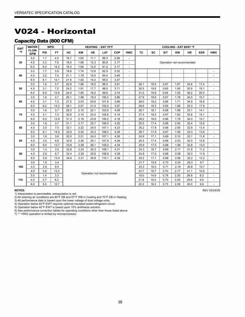
38
VERSATEC SPECIFICATION CATALOG
V024 - HorizontalCapacity Data (800 CFM)
EWT °F
WATER FLOWGPM
WPD HEATING - EAT 70°F COOLING - EAT 80/67 °F
PSI FT HC KW HE LAT COP HWC TC SC S/T KW HR EER HWC
303.0 1.7 4.0 16.7 1.63 11.1 89.3 2.99 -
Operation not recommended4.5 3.3 7.6 18.0 1.66 12.3 90.8 3.17 -6.0 6.2 14.3 18.3 1.69 12.5 91.2 3.17 -
403.0 1.7 3.9 19.8 1.74 13.8 92.9 3.32 - -4.5 3.2 7.4 21.1 1.79 15.0 94.4 3.46 - -6.0 6.1 14.1 21.6 1.82 15.4 95.0 3.47 - -
503.0 1.6 3.7 22.9 1.86 16.5 96.5 3.61 - 29.1 19.5 0.67 1.67 34.8 17.4 -4.5 3.1 7.2 24.2 1.91 17.7 98.0 3.71 - 30.5 19.8 0.65 1.60 35.9 19.1 -6.0 6.0 13.9 24.9 1.95 18.2 98.8 3.74 - 31.0 19.9 0.64 1.52 36.2 20.4 -
603.0 1.6 3.7 26.1 1.98 19.3 100.2 3.86 - 27.9 18.8 0.67 1.78 34.0 15.7 -4.5 3.1 7.2 27.5 2.03 20.6 101.8 3.96 - 29.0 19.2 0.66 1.71 34.9 16.9 -6.0 6.2 14.2 28.1 2.07 21.0 102.5 3.97 - 29.6 19.3 0.65 1.66 35.3 17.9 -
703.0 1.6 3.7 29.3 2.10 22.1 103.9 4.08 - 26.7 18.1 0.68 1.89 33.1 14.1 -4.5 3.1 7.2 30.8 2.15 23.4 105.6 4.19 - 27.5 18.5 0.67 1.83 33.8 15.1 -6.0 6.0 13.9 31.3 2.19 23.8 106.2 4.18 - 28.2 18.6 0.66 1.79 34.3 15.7 -
803.0 1.6 3.7 31.1 2.17 23.7 106.0 4.20 - 25.5 17.4 0.68 2.00 32.4 12.6 -4.5 3.0 7.0 32.1 2.22 24.5 107.1 4.23 - 26.2 17.8 0.68 2.00 32.9 13.4 -6.0 6.1 14.0 33.0 2.25 25.3 108.2 4.29 - 26.7 17.9 0.67 1.90 33.3 13.9 -
853.0 1.6 3.6 32.0 2.21 24.5 107.1 4.26 - 24.9 17.1 0.69 2.10 32.1 11.8 -4.5 3.0 6.8 32.8 2.26 25.1 107.9 4.26 - 25.5 17.4 0.68 2.03 32.5 12.6 -6.0 6.0 13.7 33.8 2.28 26.1 109.2 4.34 - 25.9 17.5 0.68 1.99 32.8 13.0 -
903.0 1.5 3.5 32.9 2.24 25.3 108.1 4.31 - 24.3 16.7 0.69 2.17 31.8 11.2 -4.5 2.9 6.7 33.4 2.29 25.6 108.6 4.28 - 24.9 17.0 0.68 2.09 32.0 11.9 -6.0 5.8 13.4 34.6 2.31 26.8 110.1 4.39 - 25.2 17.1 0.68 2.06 32.2 12.2 -
1003.0 1.5 3.4
Operation not recommended
21.7 15.8 0.73 2.24 29.3 9.7 -4.5 2.8 6.5 23.3 16.5 0.71 2.19 30.8 10.7 -6.0 5.8 13.3 23.7 16.7 0.70 2.17 31.1 10.9 -
1103.0 1.4 3.3 19.0 14.9 0.78 2.30 26.9 8.3 -4.5 2.7 6.2 21.8 16.0 0.73 2.29 29.6 9.5 -6.0 5.5 12.7 22.3 16.3 0.73 2.28 30.0 9.8 -
NOTES:1) Interpolation is permissible, extrapolation is not.2) All entering air conditions are 80°F DB and 67°F WB in Cooling and 70°F DB in Heating.3) All performance data is based upon the lower voltage of dual voltage units.4) Operation below 60°F EWT requires optional insulated water/refrigerant circuit.5) Operation below 40°F EWT is based upon 15% antifreeze solution.6) See performance correction tables for operating conditions other than those listed above.7) "-" HWG operation is limited by microprocessor.
REV 03/24/05
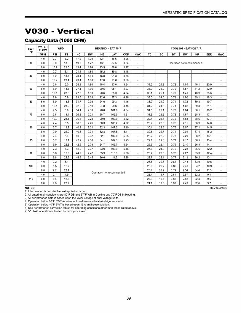
39
VERSATEC SPECIFICATION CATALOG
V030 - VerticalCapacity Data (1000 CFM)
EWT °F
WATER FLOW WPD HEATING - EAT 70°F COOLING - EAT 80/67 °F
GPM PSI FT HC KW HE LAT COP HWC TC SC S/T KW HR EER HWC
304.0 2.7 6.2 17.9 1.70 12.1 86.6 3.08 -
Operation not recommended6.0 6.0 13.9 19.0 1.72 13.1 87.5 3.24 -8.0 10.2 23.6 19.4 1.74 13.5 88.0 3.27 -
404.0 2.7 6.1 21.4 1.80 15.2 89.8 3.48 - -6.0 6.0 13.7 23.1 1.84 16.8 91.3 3.68 - -8.0 10.2 23.4 23.4 1.86 17.0 91.6 3.68 - -
504.0 2.6 6.0 24.9 1.90 18.4 93.0 3.84 - 34.5 24.9 0.72 1.65 40.1 20.9 -6.0 5.9 13.6 27.1 1.96 20.5 95.1 4.07 - 35.9 25.0 0.70 1.57 41.2 22.9 -8.0 10.1 23.3 27.3 1.98 20.6 95.3 4.04 - 36.1 25.1 0.70 1.41 40.9 25.6 -
604.0 2.6 5.9 29.5 2.03 22.6 97.3 4.26 - 33.0 24.0 0.73 1.80 39.1 18.3 -6.0 5.9 13.5 31.7 2.08 24.6 99.3 4.46 - 33.9 24.2 0.71 1.72 39.8 19.7 -8.0 10.1 23.2 32.0 2.10 24.8 99.6 4.45 - 34.2 24.3 0.71 1.62 39.8 21.1 -
704.0 2.5 5.8 34.1 2.16 26.8 101.6 4.64 - 31.5 23.1 0.73 1.94 38.1 16.2 -6.0 5.8 13.4 36.2 2.21 28.7 103.5 4.81 - 31.9 23.3 0.73 1.87 38.3 17.1 -8.0 10.0 23.1 36.6 2.23 29.0 103.9 4.82 - 32.4 23.4 0.72 1.83 38.6 17.7 -
804.0 2.4 5.5 38.0 2.26 30.3 105.2 4.92 - 29.7 22.5 0.76 2.11 36.9 14.0 -6.0 5.7 13.2 40.2 2.31 32.3 107.2 5.10 - 30.1 22.6 0.75 2.07 37.1 14.5 -8.0 9.9 22.9 40.8 2.34 32.8 107.8 5.11 - 30.5 22.7 0.74 2.01 37.4 15.2 -
854.0 2.4 5.4 40.0 2.32 32.1 107.0 5.05 - 28.7 22.2 0.77 2.20 36.2 13.1 -6.0 5.7 13.1 42.2 2.36 34.1 109.1 5.23 - 29.1 22.3 0.77 2.17 36.5 13.4 -8.0 9.9 22.8 42.9 2.39 34.7 109.7 5.24 - 29.6 22.4 0.76 2.10 36.8 14.1 -
904.0 2.3 5.3 42.0 2.37 33.9 108.9 5.18 - 27.8 21.9 0.79 2.28 35.6 12.2 -6.0 5.6 12.9 44.2 2.42 35.9 110.9 5.36 - 28.2 22.0 0.78 2.27 35.9 12.4 -8.0 9.8 22.6 44.9 2.45 36.6 111.6 5.38 - 28.7 22.1 0.77 2.19 36.2 13.1 -
1004.0 2.2 5.1
Operation not recommended
25.6 20.8 0.81 2.43 33.9 10.6 -6.0 5.5 12.7 26.0 20.7 0.80 2.40 34.2 10.9 -8.0 9.7 22.4 26.4 20.9 0.79 2.34 34.4 11.3 -
1104.0 2.1 4.9 23.4 19.7 0.84 2.57 32.2 9.1 -6.0 5.4 12.5 23.8 19.5 0.82 2.52 32.4 9.5 -8.0 9.6 22.2 24.1 19.8 0.82 2.49 32.6 9.7 -
NOTES:1) Interpolation is permissible, extrapolation is not.2) All entering air conditions are 80°F DB and 67°F WB in Cooling and 70°F DB in Heating.3) All performance data is based upon the lower voltage of dual voltage units.4) Operation below 60°F EWT requires optional insulated water/refrigerant circuit.5) Operation below 40°F EWT is based upon 15% antifreeze solution.6) See performance correction tables for operating conditions other than those listed above.7) "-" HWG operation is limited by microprocessor.
REV 03/24/05
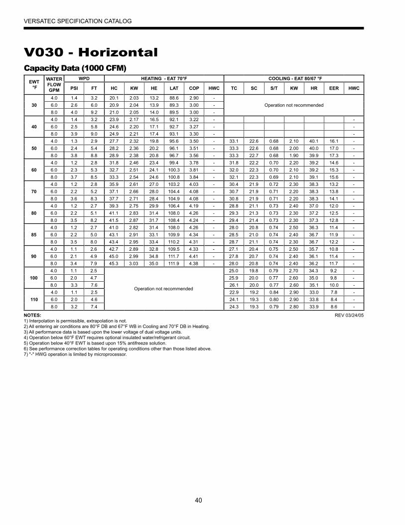
40
VERSATEC SPECIFICATION CATALOG
V030 - HorizontalCapacity Data (1000 CFM)
EWT °F
WATER FLOWGPM
WPD HEATING - EAT 70°F COOLING - EAT 80/67 °F
PSI FT HC KW HE LAT COP HWC TC SC S/T KW HR EER HWC
304.0 1.4 3.2 20.1 2.03 13.2 88.6 2.90 -
Operation not recommended6.0 2.6 6.0 20.9 2.04 13.9 89.3 3.00 -8.0 4.0 9.2 21.0 2.05 14.0 89.5 3.00 -
404.0 1.4 3.2 23.9 2.17 16.5 92.1 3.22 - -6.0 2.5 5.8 24.6 2.20 17.1 92.7 3.27 - -8.0 3.9 9.0 24.9 2.21 17.4 93.1 3.30 - -
504.0 1.3 2.9 27.7 2.32 19.8 95.6 3.50 - 33.1 22.6 0.68 2.10 40.1 16.1 -6.0 2.4 5.4 28.2 2.36 20.2 96.1 3.51 - 33.3 22.6 0.68 2.00 40.0 17.0 -8.0 3.8 8.8 28.9 2.38 20.8 96.7 3.56 - 33.3 22.7 0.68 1.90 39.9 17.3 -
604.0 1.2 2.8 31.8 2.46 23.4 99.4 3.78 - 31.8 22.2 0.70 2.20 39.2 14.6 -6.0 2.3 5.3 32.7 2.51 24.1 100.3 3.81 - 32.0 22.3 0.70 2.10 39.2 15.3 -8.0 3.7 8.5 33.3 2.54 24.6 100.8 3.84 - 32.1 22.3 0.69 2.10 39.1 15.6 -
704.0 1.2 2.8 35.9 2.61 27.0 103.2 4.03 - 30.4 21.9 0.72 2.30 38.3 13.2 -6.0 2.2 5.2 37.1 2.66 28.0 104.4 4.08 - 30.7 21.9 0.71 2.20 38.3 13.8 -8.0 3.6 8.3 37.7 2.71 28.4 104.9 4.08 - 30.8 21.9 0.71 2.20 38.3 14.1 -
804.0 1.2 2.7 39.3 2.75 29.9 106.4 4.19 - 28.8 21.1 0.73 2.40 37.0 12.0 -6.0 2.2 5.1 41.1 2.83 31.4 108.0 4.26 - 29.3 21.3 0.73 2.30 37.2 12.5 -8.0 3.5 8.2 41.5 2.87 31.7 108.4 4.24 - 29.4 21.4 0.73 2.30 37.3 12.8 -
854.0 1.2 2.7 41.0 2.82 31.4 108.0 4.26 - 28.0 20.8 0.74 2.50 36.3 11.4 -6.0 2.2 5.0 43.1 2.91 33.1 109.9 4.34 - 28.5 21.0 0.74 2.40 36.7 11.9 -8.0 3.5 8.0 43.4 2.95 33.4 110.2 4.31 - 28.7 21.1 0.74 2.30 36.7 12.2 -
904.0 1.1 2.6 42.7 2.89 32.8 109.5 4.33 - 27.1 20.4 0.75 2.50 35.7 10.8 -6.0 2.1 4.9 45.0 2.99 34.8 111.7 4.41 - 27.8 20.7 0.74 2.40 36.1 11.4 -8.0 3.4 7.9 45.3 3.03 35.0 111.9 4.38 - 28.0 20.8 0.74 2.40 36.2 11.7 -
1004.0 1.1 2.5
Operation not recommended
25.0 19.8 0.79 2.70 34.3 9.2 -6.0 2.0 4.7 25.9 20.0 0.77 2.60 35.0 9.8 -8.0 3.3 7.6 26.1 20.0 0.77 2.60 35.1 10.0 -
1104.0 1.1 2.5 22.9 19.2 0.84 2.90 33.0 7.8 -6.0 2.0 4.6 24.1 19.3 0.80 2.90 33.8 8.4 -8.0 3.2 7.4 24.3 19.3 0.79 2.80 33.9 8.6 -
NOTES:1) Interpolation is permissible, extrapolation is not.2) All entering air conditions are 80°F DB and 67°F WB in Cooling and 70°F DB in Heating.3) All performance data is based upon the lower voltage of dual voltage units.4) Operation below 60°F EWT requires optional insulated water/refrigerant circuit.5) Operation below 40°F EWT is based upon 15% antifreeze solution.6) See performance correction tables for operating conditions other than those listed above.7) "-" HWG operation is limited by microprocessor.
REV 03/24/05
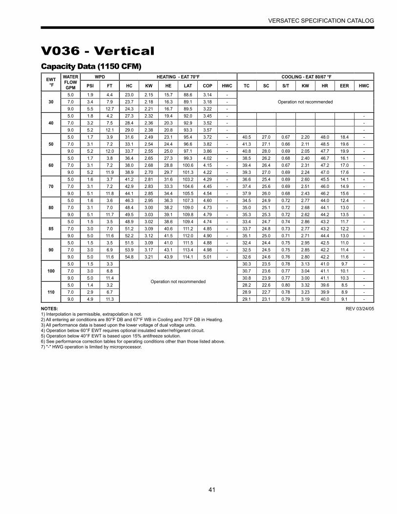
41
VERSATEC SPECIFICATION CATALOG
V036 - VerticalCapacity Data (1150 CFM)
EWT °F
WATER FLOWGPM
WPD HEATING - EAT 70°F COOLING - EAT 80/67 °F
PSI FT HC KW HE LAT COP HWC TC SC S/T KW HR EER HWC
305.0 1.9 4.4 23.0 2.15 15.7 88.6 3.14 -
Operation not recommended7.0 3.4 7.9 23.7 2.18 16.3 89.1 3.18 -9.0 5.5 12.7 24.3 2.21 16.7 89.5 3.22 -
405.0 1.8 4.2 27.3 2.32 19.4 92.0 3.45 - -7.0 3.2 7.5 28.4 2.36 20.3 92.9 3.52 - -9.0 5.2 12.1 29.0 2.38 20.8 93.3 3.57 - -
505.0 1.7 3.9 31.6 2.49 23.1 95.4 3.72 - 40.5 27.0 0.67 2.20 48.0 18.4 -7.0 3.1 7.2 33.1 2.54 24.4 96.6 3.82 - 41.3 27.1 0.66 2.11 48.5 19.6 -9.0 5.2 12.0 33.7 2.55 25.0 97.1 3.86 - 40.8 28.0 0.69 2.05 47.7 19.9 -
605.0 1.7 3.8 36.4 2.65 27.3 99.3 4.02 - 38.5 26.2 0.68 2.40 46.7 16.1 -7.0 3.1 7.2 38.0 2.68 28.8 100.6 4.15 - 39.4 26.4 0.67 2.31 47.2 17.0 -9.0 5.2 11.9 38.9 2.70 29.7 101.3 4.22 - 39.3 27.0 0.69 2.24 47.0 17.6 -
705.0 1.6 3.7 41.2 2.81 31.6 103.2 4.29 - 36.6 25.4 0.69 2.60 45.5 14.1 -7.0 3.1 7.2 42.9 2.83 33.3 104.6 4.45 - 37.4 25.6 0.69 2.51 46.0 14.9 -9.0 5.1 11.8 44.1 2.85 34.4 105.5 4.54 - 37.9 26.0 0.68 2.43 46.2 15.6 -
805.0 1.6 3.6 46.3 2.95 36.3 107.3 4.60 - 34.5 24.9 0.72 2.77 44.0 12.4 -7.0 3.1 7.0 48.4 3.00 38.2 109.0 4.73 - 35.0 25.1 0.72 2.68 44.1 13.0 -9.0 5.1 11.7 49.5 3.03 39.1 109.8 4.79 - 35.3 25.3 0.72 2.62 44.2 13.5 -
855.0 1.5 3.5 48.9 3.02 38.6 109.4 4.74 - 33.4 24.7 0.74 2.86 43.2 11.7 -7.0 3.0 7.0 51.2 3.09 40.6 111.2 4.85 - 33.7 24.8 0.73 2.77 43.2 12.2 -9.0 5.0 11.6 52.2 3.12 41.5 112.0 4.90 - 35.1 25.0 0.71 2.71 44.4 13.0 -
905.0 1.5 3.5 51.5 3.09 41.0 111.5 4.88 - 32.4 24.4 0.75 2.95 42.5 11.0 -7.0 3.0 6.9 53.9 3.17 43.1 113.4 4.98 - 32.5 24.5 0.75 2.85 42.2 11.4 -9.0 5.0 11.6 54.8 3.21 43.9 114.1 5.01 - 32.6 24.6 0.76 2.80 42.2 11.6 -
1005.0 1.5 3.3
Operation not recommended
30.3 23.5 0.78 3.13 41.0 9.7 -7.0 3.0 6.8 30.7 23.6 0.77 3.04 41.1 10.1 -9.0 5.0 11.4 30.8 23.9 0.77 3.00 41.1 10.3 -
1105.0 1.4 3.2 28.2 22.6 0.80 3.32 39.6 8.5 -7.0 2.9 6.7 28.9 22.7 0.78 3.23 39.9 8.9 -9.0 4.9 11.3 29.1 23.1 0.79 3.19 40.0 9.1 -
NOTES:1) Interpolation is permissible, extrapolation is not.2) All entering air conditions are 80°F DB and 67°F WB in Cooling and 70°F DB in Heating.3) All performance data is based upon the lower voltage of dual voltage units.4) Operation below 60°F EWT requires optional insulated water/refrigerant circuit.5) Operation below 40°F EWT is based upon 15% antifreeze solution.6) See performance correction tables for operating conditions other than those listed above.7) "-" HWG operation is limited by microprocessor.
REV 03/24/05

42
VERSATEC SPECIFICATION CATALOG
V036 - HorizontalCapacity Data (1150 CFM)
EWT °F
WATER FLOWGPM
WPD HEATING - EAT 70°F COOLING - EAT 80/67 °F
PSI FT HC KW HE LAT COP HWC TC SC S/T KW HR EER HWC
305.0 2.1 4.9 22.9 2.16 15.5 88.4 3.11 -
Operation not recommended7.0 3.8 8.8 23.1 2.19 15.7 88.6 3.10 -9.0 5.5 12.7 23.4 2.22 15.9 88.9 3.10 -
405.0 2.0 4.6 27.2 2.33 19.2 91.9 3.42 - -7.0 3.7 8.5 27.8 2.37 19.7 92.3 3.44 - -9.0 5.4 12.5 28.4 2.40 20.2 92.8 3.46 - -
505.0 1.9 4.4 31.5 2.51 22.9 95.4 3.68 - 38.5 25.8 0.67 2.22 46.0 17.4 -7.0 3.6 8.3 32.4 2.55 23.7 96.1 3.72 - 38.9 26.2 0.67 2.11 46.1 18.5 -9.0 5.3 12.2 33.3 2.59 24.5 96.8 3.78 - 39.2 26.4 0.67 2.06 46.2 19.1 -
605.0 1.9 4.3 36.0 2.73 26.7 99.0 3.87 - 36.5 25.3 0.69 2.40 44.7 15.2 -7.0 3.5 8.0 37.3 2.77 27.9 100.1 3.94 - 37.1 25.4 0.68 2.30 45.0 16.1 -9.0 5.1 11.7 38.4 2.82 28.7 100.9 3.98 - 37.3 25.7 0.69 2.23 44.9 16.7 -
705.0 1.8 4.2 40.6 2.94 30.5 102.7 4.04 - 34.6 24.9 0.72 2.58 43.4 13.4 -7.0 3.4 7.9 42.3 3.00 32.0 104.1 4.13 - 35.3 24.6 0.70 2.50 43.8 14.1 -9.0 5.0 11.6 43.4 3.06 33.0 105.0 4.16 - 35.3 25.0 0.71 2.40 43.5 14.7 -
805.0 1.8 4.1 44.1 3.08 33.6 105.5 4.20 - 32.8 24.1 0.73 2.75 42.2 11.9 -7.0 3.3 7.7 45.9 3.14 35.2 106.9 4.29 - 33.4 24.2 0.72 2.67 42.5 12.5 -9.0 4.9 11.2 47.1 3.22 36.1 107.9 4.29 - 33.7 24.5 0.73 2.59 42.5 13.0 -
855.0 1.8 4.0 45.8 3.15 35.1 106.9 4.27 - 32.0 23.8 0.74 2.83 41.6 11.3 -7.0 3.3 7.6 47.7 3.21 36.8 108.4 4.36 - 32.4 24.0 0.74 2.76 41.8 11.8 -9.0 4.9 11.2 49.0 3.31 37.7 109.4 4.35 - 32.8 24.3 0.74 2.69 42.0 12.2 -
905.0 1.7 3.9 47.5 3.21 36.6 108.3 4.34 - 31.1 23.4 0.75 2.92 41.1 10.6 -7.0 3.3 7.5 49.5 3.27 38.3 109.8 4.43 - 31.4 23.8 0.76 2.84 41.1 11.1 -9.0 4.8 11.1 50.9 3.39 39.3 110.9 4.40 - 32.0 24.0 0.75 2.78 41.5 11.5 -
1005.0 1.7 3.8
Operation not recommended
30.0 21.9 0.73 3.16 40.7 9.5 -7.0 3.2 7.3 29.5 23.0 0.78 3.00 39.7 9.8 -9.0 4.7 10.7 30.0 23.2 0.77 2.97 40.1 10.1 -
1105.0 1.6 3.7 28.9 20.4 0.71 3.39 40.4 8.5 -7.0 3.1 7.0 27.5 22.3 0.81 3.16 38.3 8.7 -9.0 4.5 10.4 28.0 22.5 0.80 3.15 38.8 8.9 -
NOTES:1) Interpolation is permissible, extrapolation is not.2) All entering air conditions are 80°F DB and 67°F WB in Cooling and 70°F DB in Heating.3) All performance data is based upon the lower voltage of dual voltage units.4) Operation below 60°F EWT requires optional insulated water/refrigerant circuit.5) Operation below 40°F EWT is based upon 15% antifreeze solution.6) See performance correction tables for operating conditions other than those listed above.7) "-" HWG operation is limited by microprocessor.
REV 03/24/05

43
VERSATEC SPECIFICATION CATALOG
V042 - VerticalCapacity Data (1350 CFM)
NOTES:1) Interpolation is permissible, extrapolation is not.2) All entering air conditions are 80°F DB and 67°F WB in Cooling and 70°F DB in Heating.3) All performance data is based upon the lower voltage of dual voltage units.4) Operation below 60°F EWT requires optional insulated water/refrigerant circuit.5) Operation below 40°F EWT is based upon 15% antifreeze solution.6) See performance correction tables for operating conditions other than those listed above.7) "-" HWG operation is limited by microprocessor.
REV 03/24/05
EWT °F
WATER FLOWGPM
WPD HEATING - EAT 70°F COOLING - EAT 80/67 °F
PSI FT HC KW HE LAT COP HWC TC SC S/T KW HR EER HWC
305.0 2.0 4.6 25.4 2.47 16.9 87.4 3.01 -
Operation not recommended8.0 4.6 10.6 26.8 2.52 18.2 88.4 3.11 -11.0 8.2 18.9 27.6 2.54 18.9 88.9 3.18 -
405.0 1.9 4.4 30.1 2.65 21.0 90.6 3.33 - -8.0 4.5 10.4 31.8 2.71 22.6 91.8 3.45 - -11.0 8.1 18.7 32.6 2.74 23.2 92.4 3.49 - -
505.0 1.8 4.2 34.8 2.82 25.1 93.9 3.61 - 47.9 32.5 0.68 2.52 56.5 19.0 -8.0 4.4 10.2 36.9 2.89 27.0 95.3 3.74 - 49.2 32.8 0.67 2.36 57.2 20.9 -11.0 8.0 18.5 37.6 2.94 27.6 95.8 3.75 - 49.3 33.3 0.68 2.28 57.1 21.6 -
605.0 1.8 4.0 40.0 2.98 29.9 97.5 3.93 - 45.3 31.7 0.70 2.73 54.7 16.6 -8.0 4.4 10.0 42.6 3.06 32.1 99.2 4.08 - 46.8 31.8 0.68 2.58 55.6 18.1 -11.0 8.0 18.4 43.7 3.10 33.1 100.0 4.13 - 47.1 32.5 0.69 2.50 55.7 18.9 -
705.0 1.7 3.9 45.3 3.14 34.6 101.1 4.23 - 42.8 31.0 0.72 2.95 52.9 14.5 -8.0 4.3 9.9 48.3 3.23 37.2 103.1 4.38 - 44.4 30.7 0.69 2.80 53.9 15.8 -11.0 7.9 18.2 49.8 3.27 38.6 104.2 4.46 - 45.0 31.8 0.71 2.71 54.2 16.6 -
805.0 1.6 3.7 50.8 3.28 39.6 104.8 4.54 - 40.8 29.1 0.71 3.16 51.6 12.9 -8.0 4.2 9.6 54.5 3.40 42.9 107.4 4.69 - 41.8 29.2 0.70 3.05 52.2 13.7 -11.0 7.8 17.9 56.4 3.46 44.6 108.7 4.77 - 42.3 29.9 0.71 2.97 52.4 14.3 -
855.0 1.6 3.6 53.5 3.34 42.1 106.7 4.68 - 39.9 28.2 0.71 3.27 51.0 12.2 -8.0 4.1 9.4 57.6 3.49 45.7 109.5 4.83 - 40.5 28.5 0.70 3.17 51.3 12.8 -11.0 7.7 17.7 59.6 3.56 47.5 110.9 4.91 - 40.9 29.0 0.71 3.09 51.5 13.2 -
905.0 1.5 3.5 56.2 3.41 44.6 108.6 4.83 - 38.9 27.3 0.70 3.38 50.4 11.5 -8.0 4.0 9.2 60.7 3.58 48.5 111.6 4.97 - 39.2 27.7 0.71 3.30 50.5 11.9 -11.0 7.6 17.6 62.9 3.65 50.5 113.2 5.05 - 39.6 28.1 0.71 3.22 50.6 12.3 -
1005.0 1.5 3.3
Operation not recommended
36.0 27.0 0.75 3.61 48.3 10.0 -8.0 4.0 9.1 36.4 27.3 0.75 3.51 48.3 10.3 -11.0 7.5 17.3 36.7 27.6 0.75 3.45 48.4 10.6 -
1105.0 1.4 3.2 33.0 26.7 0.81 3.85 46.2 8.6 -8.0 3.9 9.0 33.5 26.9 0.80 3.73 46.2 9.0 -11.0 7.4 17.1 33.7 27.0 0.80 3.67 46.3 9.2 -

44
VERSATEC SPECIFICATION CATALOG
V042 - HorizontalCapacity Data (1350 CFM)
EWT °F
WATER FLOWGPM
WPD HEATING - EAT 70°F COOLING - EAT 80/67 °F
PSI FT HC KW HE LAT COP HWC TC SC S/T KW HR EER HWC
305.0 2.1 4.9 24.2 2.46 15.8 86.6 2.88 -
Operation not recommended8.0 4.7 10.9 25.6 2.52 17.0 87.6 2.98 -11.0 8.6 19.9 26.6 2.56 17.9 88.3 3.05 -
405.0 2.0 4.6 28.6 2.60 19.7 89.6 3.22 - -8.0 4.7 10.9 30.5 2.67 21.4 90.9 3.35 - -11.0 8.6 19.9 32.1 2.74 22.7 92.0 3.43 - -
505.0 1.9 4.4 33.0 2.74 23.6 92.6 3.53 - 47.0 30.7 0.65 2.51 55.5 18.7 -8.0 4.7 10.9 35.3 2.81 25.7 94.2 3.68 - 47.8 31.3 0.66 2.32 55.7 20.6 -11.0 8.6 19.9 37.5 2.92 27.5 95.7 3.77 - 48.1 31.6 0.66 2.25 55.8 21.4 -
605.0 1.9 4.3 38.5 2.87 28.7 96.4 3.93 - 44.6 29.8 0.67 2.71 53.9 16.4 -8.0 4.6 10.6 41.2 2.95 31.2 98.3 4.10 - 45.6 30.3 0.66 2.53 54.3 18.0 -11.0 8.5 19.5 43.1 3.02 32.8 99.5 4.18 - 46.6 30.6 0.66 2.48 55.1 18.8 -
705.0 1.8 4.2 43.9 3.00 33.7 100.1 4.29 - 42.3 28.9 0.68 2.91 52.3 14.5 -8.0 4.5 10.4 47.2 3.09 36.6 102.4 4.48 - 43.5 29.3 0.67 2.74 52.9 15.9 -11.0 8.3 19.2 48.7 3.12 38.0 103.4 4.57 - 45.1 29.5 0.65 2.70 54.3 16.7 -
805.0 1.8 4.1 49.7 3.16 38.9 104.1 4.61 - 39.9 27.8 0.70 3.13 50.6 12.7 -8.0 4.5 10.3 53.2 3.26 42.1 106.5 4.78 - 40.8 28.2 0.69 2.98 50.9 13.7 -11.0 8.2 18.9 54.5 3.29 43.3 107.4 4.85 - 42.0 28.9 0.69 2.92 52.0 14.4 -
855.0 1.7 4.0 52.6 3.24 41.5 106.1 4.75 - 38.7 27.2 0.70 3.24 49.7 12.0 -8.0 4.4 10.2 56.2 3.34 44.8 108.5 4.92 - 39.4 27.6 0.70 3.10 50.0 12.7 -11.0 8.1 18.7 57.5 3.38 45.9 109.4 4.98 - 40.5 28.6 0.71 3.03 50.8 13.4 -
905.0 1.7 3.9 55.5 3.32 44.1 108.0 4.90 - 37.5 26.6 0.71 3.34 48.9 11.2 -8.0 4.4 10.2 59.2 3.43 47.5 110.6 5.06 - 38.0 27.0 0.71 3.22 49.0 11.8 -11.0 8.0 18.5 60.4 3.46 48.6 111.4 5.11 - 38.9 28.3 0.73 3.14 49.6 12.4 -
1005.0 1.7 3.9
Operation not recommended
35.0 25.6 0.73 3.55 47.1 9.8 -8.0 4.4 10.2 35.5 25.9 0.73 3.49 47.4 10.2 -11.0 8.0 18.5 36.2 26.9 0.74 3.37 47.7 10.8 -
1105.0 1.7 3.9 32.5 24.6 0.76 3.76 45.3 8.6 -8.0 4.4 10.2 32.9 24.8 0.75 3.76 45.7 8.8 -11.0 8.0 18.5 33.6 25.5 0.76 3.60 45.9 9.3 -
NOTES:1) Interpolation is permissible, extrapolation is not.2) All entering air conditions are 80°F DB and 67°F WB in Cooling and 70°F DB in Heating.3) All performance data is based upon the lower voltage of dual voltage units.4) Operation below 60°F EWT requires optional insulated water/refrigerant circuit.5) Operation below 40°F EWT is based upon 15% antifreeze solution.6) See performance correction tables for operating conditions other than those listed above.7) "-" HWG operation is limited by microprocessor.
REV 03/24/05
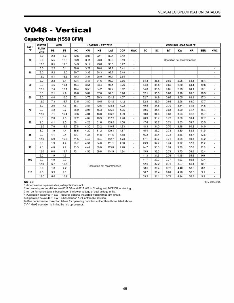
45
VERSATEC SPECIFICATION CATALOG
V048 - VerticalCapacity Data (1550 CFM)
EWT °F
WATER FLOWGPM
WPD HEATING - EAT 70°F COOLING - EAT 80/67 °F
PSI FT HC KW HE LAT COP HWC TC SC S/T KW HR EER HWC
306.0 2.3 5.3 32.5 3.06 22.1 89.4 3.12 -
Operation not recommended9.0 5.5 12.6 33.9 3.11 23.3 90.3 3.19 -12.0 8.5 19.5 34.3 3.12 23.6 90.5 3.22 -
406.0 2.2 5.1 38.0 3.27 26.8 92.7 3.41 - -9.0 5.2 12.0 39.7 3.33 28.3 93.7 3.49 - -
12.0 8.1 18.6 40.3 3.34 28.9 94.1 3.54 - -
506.0 2.2 5.1 43.4 3.47 31.6 95.9 3.66 - 54.3 35.8 0.66 2.95 64.4 18.4 -9.0 4.5 10.4 45.4 3.54 33.4 97.1 3.76 - 54.8 35.5 0.65 2.80 64.4 19.6 -
12.0 7.4 17.1 46.4 3.55 34.2 97.7 3.82 - 54.8 35.5 0.65 2.73 64.1 20.1 -
606.0 2.1 4.9 49.6 3.67 37.0 99.6 3.96 - 52.1 35.3 0.68 3.20 63.0 16.3 -9.0 4.4 10.0 52.1 3.75 39.3 101.2 4.07 - 52.7 34.9 0.66 3.05 63.1 17.3 -
12.0 7.3 16.7 53.5 3.80 40.5 101.9 4.12 - 52.8 35.0 0.66 2.98 63.0 17.7 -
706.0 2.0 4.6 55.7 3.87 42.5 103.3 4.22 - 49.8 34.8 0.70 3.44 61.6 14.5 -9.0 4.2 9.7 58.9 3.97 45.3 105.2 4.35 - 50.5 34.4 0.68 3.29 61.7 15.4 -
12.0 7.1 16.4 60.6 4.04 46.8 106.2 4.39 - 50.8 34.6 0.68 3.23 61.8 15.7 -
806.0 2.0 4.5 62.2 4.09 48.3 107.2 4.46 - 46.9 33.7 0.72 3.68 59.4 12.7 -9.0 4.1 9.5 66.1 4.23 51.6 109.5 4.58 - 47.6 33.7 0.71 3.53 59.7 13.5 -
12.0 7.0 16.1 67.8 4.30 53.2 110.5 4.63 - 48.3 34.0 0.70 3.46 60.2 14.0 -
856.0 1.9 4.4 65.5 4.20 51.2 109.1 4.57 - 45.4 33.2 0.73 3.80 58.4 11.9 -9.0 4.1 9.4 69.7 4.36 54.8 111.6 4.68 - 46.2 33.4 0.72 3.66 58.7 12.6 -
12.0 6.9 15.9 71.5 4.42 56.4 112.7 4.73 - 47.1 33.7 0.71 3.58 59.3 13.2 -
906.0 1.9 4.4 68.7 4.31 54.0 111.1 4.68 - 43.9 32.7 0.74 3.92 57.3 11.2 -9.0 4.0 9.2 73.3 4.49 58.0 113.8 4.78 - 44.7 33.0 0.74 3.78 57.6 11.8 -
12.0 6.8 15.7 75.1 4.55 59.6 114.9 4.84 - 45.9 33.3 0.73 3.70 58.5 12.4 -
1006.0 1.9 4.3
Operation not recommended
41.3 31.5 0.76 4.16 55.5 9.9 -9.0 4.0 9.2 41.7 32.2 0.77 4.03 55.5 10.4 -
12.0 6.7 15.5 42.6 32.2 0.76 3.97 56.1 10.7 -
1106.0 1.8 4.2 38.6 30.4 0.79 4.40 53.6 8.8 -9.0 3.9 9.1 38.7 31.4 0.81 4.28 53.3 9.1 -
12.0 6.6 15.2 39.3 31.1 0.79 4.24 53.7 9.3 -
NOTES:1) Interpolation is permissible, extrapolation is not.2) All entering air conditions are 80°F DB and 67°F WB in Cooling and 70°F DB in Heating.3) All performance data is based upon the lower voltage of dual voltage units.4) Operation below 60°F EWT requires optional insulated water/refrigerant circuit.5) Operation below 40°F EWT is based upon 15% antifreeze solution.6) See performance correction tables for operating conditions other than those listed above.7) "-" HWG operation is limited by microprocessor.
REV 03/24/05
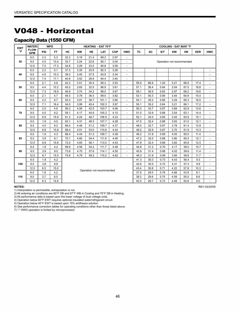
46
VERSATEC SPECIFICATION CATALOG
V048 - HorizontalCapacity Data (1550 CFM)
EWT °F
WATER FLOWGPM
WPD HEATING - EAT 70°F COOLING - EAT 80/67 °F
PSI FT HC KW HE LAT COP HWC TC SC S/T KW HR EER HWC
306.0 2.3 5.3 32.3 3.19 21.4 89.3 2.97 -
Operation not recommended9.0 4.5 10.4 33.7 3.24 22.6 90.1 3.04 -12.0 7.5 17.3 34.8 3.29 23.5 90.8 3.09 -
406.0 2.2 5.1 37.3 3.35 25.9 92.3 3.26 - -9.0 4.5 10.3 39.3 3.45 27.5 93.5 3.34 - -12.0 7.4 17.1 40.8 3.52 28.8 94.4 3.40 - -
506.0 2.1 4.9 42.3 3.51 30.4 95.3 3.53 - 55.9 66.9 1.20 3.21 66.9 17.4 -9.0 4.4 10.2 45.0 3.65 32.5 96.9 3.61 - 57.1 36.4 0.64 3.04 67.5 18.8 -12.0 7.3 16.9 46.9 3.74 34.2 98.0 3.67 - 58.1 36.5 0.63 2.97 68.2 19.6 -
606.0 2.1 4.7 49.3 3.79 36.4 99.5 3.82 - 53.1 50.3 0.95 3.45 64.9 15.4 -9.0 4.2 9.7 52.0 3.91 38.7 101.1 3.90 - 54.1 35.2 0.65 3.29 65.3 16.5 -12.0 7.1 16.4 54.0 3.99 40.4 102.3 3.97 - 55.1 35.2 0.64 3.21 66.1 17.2 -
706.0 2.0 4.6 56.3 4.06 42.5 103.7 4.06 - 50.3 33.7 0.67 3.69 62.9 13.6 -9.0 4.0 9.2 59.1 4.17 44.9 105.3 4.15 - 51.0 33.9 0.66 3.54 63.1 14.4 -12.0 6.9 15.9 61.2 4.24 46.7 106.5 4.23 - 52.1 34.0 0.65 3.45 63.9 15.1 -
806.0 1.9 4.5 63.1 4.31 48.3 107.7 4.28 - 47.5 32.4 0.68 3.93 61.0 12.1 -9.0 4.0 9.2 66.4 4.46 51.2 109.7 4.37 - 48.5 32.7 0.67 3.78 61.4 12.8 -12.0 6.8 15.8 68.4 4.51 53.0 110.8 4.44 - 49.2 32.9 0.67 3.70 61.9 13.3 -
856.0 1.9 4.3 66.4 4.44 51.3 109.7 4.38 - 46.2 31.8 0.69 4.05 60.0 11.4 -9.0 3.9 9.1 70.1 4.60 54.4 111.9 4.46 - 47.2 32.0 0.68 3.90 60.5 12.1 -12.0 6.8 15.6 72.0 4.65 56.1 113.0 4.53 - 47.8 32.4 0.68 3.82 60.8 12.5 -
906.0 1.8 4.2 69.8 4.56 54.2 111.7 4.48 - 44.8 31.2 0.70 4.17 59.0 10.7 -9.0 3.9 9.0 73.8 4.75 57.6 114.1 4.55 - 45.9 31.4 0.68 4.02 59.6 11.4 -12.0 6.7 15.5 75.6 4.79 59.2 115.2 4.62 - 46.3 31.9 0.69 3.95 59.8 11.7 -
1006.0 1.8 4.2
Operation not recommended
41.3 30.3 0.73 4.43 56.4 9.3 -9.0 3.8 8.8 42.6 30.5 0.72 4.31 57.3 9.9 -12.0 6.5 15.0 43.4 30.8 0.71 4.22 57.8 10.3 -
1106.0 1.8 4.2 37.9 29.5 0.78 4.68 53.9 8.1 -9.0 3.7 8.5 39.3 29.6 0.75 4.59 55.0 8.6 -12.0 6.3 14.6 40.5 29.7 0.73 4.49 55.8 9.0 -
NOTES:1) Interpolation is permissible, extrapolation is not.2) All entering air conditions are 80°F DB and 67°F WB in Cooling and 70°F DB in Heating.3) All performance data is based upon the lower voltage of dual voltage units.4) Operation below 60°F EWT requires optional insulated water/refrigerant circuit.5) Operation below 40°F EWT is based upon 15% antifreeze solution.6) See performance correction tables for operating conditions other than those listed above.7) "-" HWG operation is limited by microprocessor.
REV 03/24/05

47
VERSATEC SPECIFICATION CATALOG
V058 - VerticalCapacity Data (2000 CFM)
EWT °F
WATER FLOWGPM
WPD HEATING - EAT 70°F COOLING - EAT 80/67 °F
PSI FT HC KW HE LAT COP HWC TC SC S/T KW HR EER HWC
308.0 3.6 8.3 39.0 3.83 26.0 88.1 2.99 -
Operation not recommended11.0 5.6 12.9 40.3 3.83 27.2 88.7 3.08 -14.0 7.9 18.2 42.2 3.82 29.2 89.6 3.24 -
408.0 3.5 8.1 46.8 4.04 33.0 91.7 3.39 - -11.0 5.5 12.7 48.3 4.05 34.5 92.4 3.49 - -14.0 7.8 18.0 50.2 4.08 36.2 93.2 3.60 - -
508.0 3.4 7.9 54.6 4.25 40.1 95.3 3.76 - 69.3 47.5 0.69 3.72 82.0 18.6 -11.0 5.4 12.5 56.4 4.28 41.8 96.1 3.86 - 69.8 47.9 0.69 3.66 82.3 19.1 -14.0 7.7 17.8 58.1 4.35 43.2 96.9 3.91 - 70.1 48.1 0.69 3.57 82.3 19.6 -
608.0 3.4 7.7 62.8 4.53 47.4 99.1 4.06 - 66.6 45.9 0.69 4.03 80.3 16.5 -11.0 5.3 12.1 64.6 4.57 49.0 99.9 4.14 - 66.6 46.4 0.70 3.93 80.0 17.0 -14.0 7.5 17.3 65.8 4.61 50.1 100.5 4.18 - 66.5 46.5 0.70 3.85 79.6 17.3 -
708.0 3.3 7.6 71.1 4.82 54.6 102.9 4.32 - 63.9 44.3 0.69 4.33 78.7 14.8 -11.0 5.1 11.8 72.9 4.86 56.3 103.7 4.40 - 63.3 44.9 0.71 4.20 77.7 15.1 -14.0 7.3 16.9 73.6 4.88 56.9 104.1 4.42 - 62.8 44.9 0.71 4.13 76.9 15.2 -
808.0 3.2 7.4 70.3 4.67 54.3 102.5 4.40 - 59.7 43.5 0.73 4.71 75.8 12.7 -11.0 5.1 11.7 80.7 5.12 63.2 107.3 4.62 - 59.7 43.9 0.74 4.50 75.0 13.3 -14.0 7.1 16.4 81.9 5.17 64.3 107.9 4.64 - 59.8 43.9 0.73 4.41 74.9 13.6 -
858.0 3.2 7.3 77.3 4.98 60.3 105.8 4.54 - 57.6 43.1 0.75 4.90 74.3 11.7 -11.0 5.0 11.6 84.6 5.25 66.6 109.1 4.72 - 57.8 43.4 0.75 4.64 73.7 12.4 -14.0 7.0 16.2 86.1 5.32 67.9 109.9 4.74 - 58.3 43.4 0.75 4.55 73.8 12.8 -
908.0 3.1 7.2 84.3 5.29 66.2 109.0 4.67 - 55.5 42.7 0.77 5.10 72.9 10.9 -11.0 5.0 11.6 88.5 5.38 70.1 110.9 4.82 - 56.0 42.9 0.77 4.79 72.3 11.7 -14.0 6.9 15.9 90.3 5.47 71.6 111.8 4.84 - 56.8 43.0 0.76 4.69 72.8 12.1 -
1008.0 3.1 7.2
Operation not recommended
53.2 41.5 0.78 5.39 71.6 9.9 -11.0 4.9 11.2 53.7 41.8 0.78 5.13 71.2 10.5 -14.0 6.7 15.4 54.1 42.1 0.78 5.03 71.3 10.8 -
1108.0 3.1 7.2 51.0 40.3 0.79 5.68 70.4 9.0 -11.0 4.7 10.9 51.4 40.8 0.79 5.46 70.0 9.4 -14.0 6.4 14.8 51.5 41.2 0.80 5.36 69.8 9.6 -
NOTES:1) Interpolation is permissible, extrapolation is not.2) All entering air conditions are 80°F DB and 67°F WB in Cooling and 70°F DB in Heating.3) All performance data is based upon the lower voltage of dual voltage units.4) Operation below 60°F EWT requires optional insulated water/refrigerant circuit.5) Operation below 40°F EWT is based upon 15% antifreeze solution.6) See performance correction tables for operating conditions other than those listed above.7) "-" HWG operation is limited by microprocessor.
REV 03/24/05
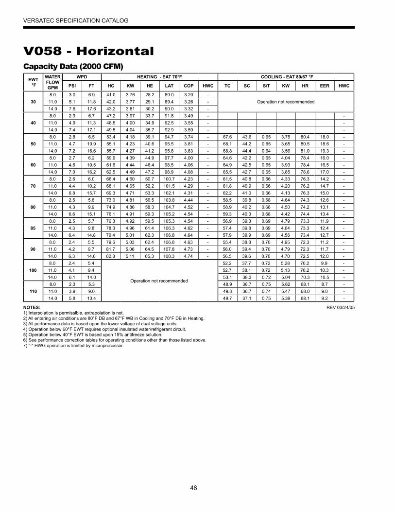
48
VERSATEC SPECIFICATION CATALOG
V058 - HorizontalCapacity Data (2000 CFM)
EWT °F
WATER FLOWGPM
WPD HEATING - EAT 70°F COOLING - EAT 80/67 °F
PSI FT HC KW HE LAT COP HWC TC SC S/T KW HR EER HWC
308.0 3.0 6.9 41.0 3.76 28.2 89.0 3.20 -
Operation not recommended11.0 5.1 11.8 42.0 3.77 29.1 89.4 3.26 -14.0 7.6 17.6 43.2 3.81 30.2 90.0 3.32 -
408.0 2.9 6.7 47.2 3.97 33.7 91.8 3.49 - -11.0 4.9 11.3 48.5 4.00 34.9 92.5 3.55 - -14.0 7.4 17.1 49.5 4.04 35.7 92.9 3.59 - -
508.0 2.8 6.5 53.4 4.18 39.1 94.7 3.74 - 67.6 43.6 0.65 3.75 80.4 18.0 -11.0 4.7 10.9 55.1 4.23 40.6 95.5 3.81 - 68.1 44.2 0.65 3.65 80.5 18.6 -14.0 7.2 16.6 55.7 4.27 41.2 95.8 3.83 - 68.8 44.4 0.64 3.56 81.0 19.3 -
608.0 2.7 6.2 59.9 4.39 44.9 97.7 4.00 - 64.6 42.2 0.65 4.04 78.4 16.0 -11.0 4.6 10.5 61.6 4.44 46.4 98.5 4.06 - 64.9 42.5 0.65 3.93 78.4 16.5 -14.0 7.0 16.2 62.5 4.49 47.2 98.9 4.08 - 65.5 42.7 0.65 3.85 78.6 17.0 -
708.0 2.6 6.0 66.4 4.60 50.7 100.7 4.23 - 61.5 40.8 0.66 4.33 76.3 14.2 -11.0 4.4 10.2 68.1 4.65 52.2 101.5 4.29 - 61.8 40.9 0.66 4.20 76.2 14.7 -14.0 6.8 15.7 69.3 4.71 53.3 102.1 4.31 - 62.2 41.0 0.66 4.13 76.3 15.0 -
808.0 2.5 5.8 73.0 4.81 56.5 103.8 4.44 - 58.5 39.8 0.68 4.64 74.3 12.6 -11.0 4.3 9.9 74.9 4.86 58.3 104.7 4.52 - 58.9 40.2 0.68 4.50 74.2 13.1 -14.0 6.6 15.1 76.1 4.91 59.3 105.2 4.54 - 59.3 40.3 0.68 4.42 74.4 13.4 -
858.0 2.5 5.7 76.3 4.92 59.5 105.3 4.54 - 56.9 39.3 0.69 4.79 73.3 11.9 -11.0 4.3 9.8 78.3 4.96 61.4 106.3 4.62 - 57.4 39.8 0.69 4.64 73.3 12.4 -14.0 6.4 14.8 79.4 5.01 62.3 106.8 4.64 - 57.9 39.9 0.69 4.56 73.4 12.7 -
908.0 2.4 5.5 79.6 5.03 62.4 106.8 4.63 - 55.4 38.8 0.70 4.95 72.3 11.2 -11.0 4.2 9.7 81.7 5.06 64.5 107.8 4.73 - 56.0 39.4 0.70 4.79 72.3 11.7 -14.0 6.3 14.6 82.8 5.11 65.3 108.3 4.74 - 56.5 39.6 0.70 4.70 72.5 12.0 -
1008.0 2.4 5.4
Operation not recommended
52.2 37.7 0.72 5.28 70.2 9.9 -11.0 4.1 9.4 52.7 38.1 0.72 5.13 70.2 10.3 -14.0 6.1 14.0 53.1 38.3 0.72 5.04 70.3 10.5 -
1108.0 2.3 5.3 48.9 36.7 0.75 5.62 68.1 8.7 -11.0 3.9 9.0 49.3 36.7 0.74 5.47 68.0 9.0 -14.0 5.8 13.4 49.7 37.1 0.75 5.39 68.1 9.2 -
NOTES:1) Interpolation is permissible, extrapolation is not.2) All entering air conditions are 80°F DB and 67°F WB in Cooling and 70°F DB in Heating.3) All performance data is based upon the lower voltage of dual voltage units.4) Operation below 60°F EWT requires optional insulated water/refrigerant circuit.5) Operation below 40°F EWT is based upon 15% antifreeze solution.6) See performance correction tables for operating conditions other than those listed above.7) "-" HWG operation is limited by microprocessor.
REV 03/24/05
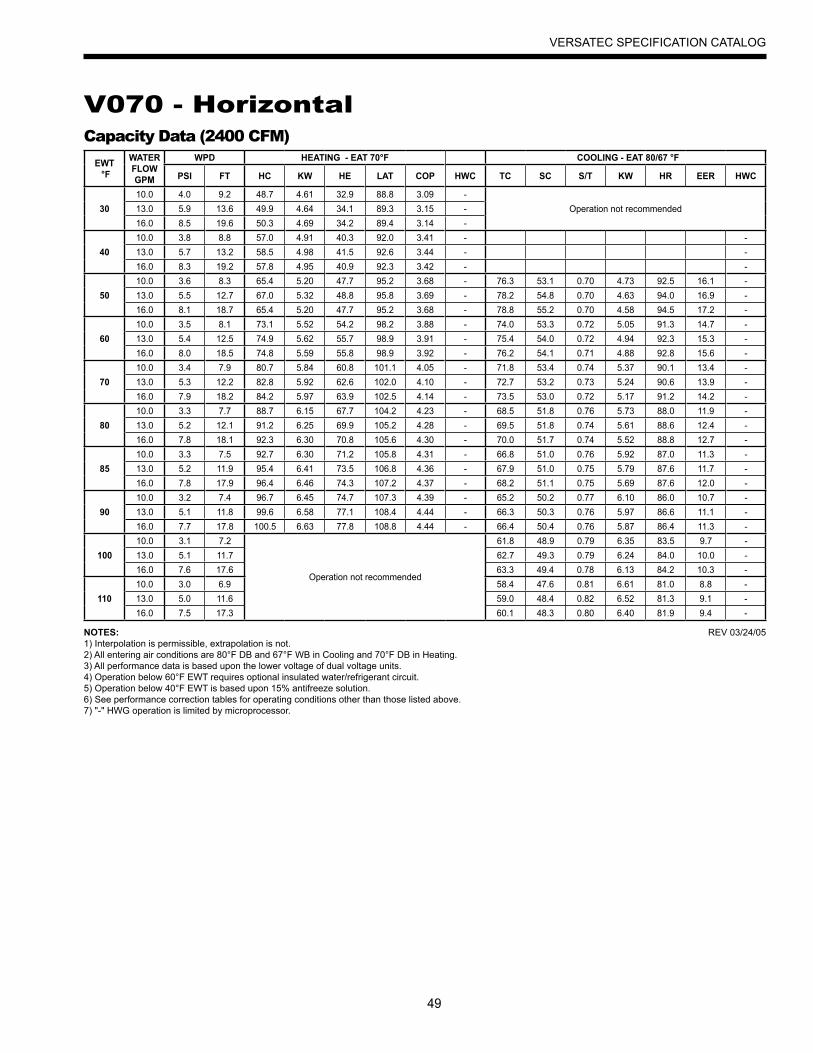
49
VERSATEC SPECIFICATION CATALOG
V070 - HorizontalCapacity Data (2400 CFM)
EWT °F
WATER FLOWGPM
WPD HEATING - EAT 70°F COOLING - EAT 80/67 °F
PSI FT HC KW HE LAT COP HWC TC SC S/T KW HR EER HWC
3010.0 4.0 9.2 48.7 4.61 32.9 88.8 3.09 -
Operation not recommended13.0 5.9 13.6 49.9 4.64 34.1 89.3 3.15 -16.0 8.5 19.6 50.3 4.69 34.2 89.4 3.14 -
4010.0 3.8 8.8 57.0 4.91 40.3 92.0 3.41 - -13.0 5.7 13.2 58.5 4.98 41.5 92.6 3.44 - -16.0 8.3 19.2 57.8 4.95 40.9 92.3 3.42 - -
5010.0 3.6 8.3 65.4 5.20 47.7 95.2 3.68 - 76.3 53.1 0.70 4.73 92.5 16.1 -13.0 5.5 12.7 67.0 5.32 48.8 95.8 3.69 - 78.2 54.8 0.70 4.63 94.0 16.9 -16.0 8.1 18.7 65.4 5.20 47.7 95.2 3.68 - 78.8 55.2 0.70 4.58 94.5 17.2 -
6010.0 3.5 8.1 73.1 5.52 54.2 98.2 3.88 - 74.0 53.3 0.72 5.05 91.3 14.7 -13.0 5.4 12.5 74.9 5.62 55.7 98.9 3.91 - 75.4 54.0 0.72 4.94 92.3 15.3 -16.0 8.0 18.5 74.8 5.59 55.8 98.9 3.92 - 76.2 54.1 0.71 4.88 92.8 15.6 -
7010.0 3.4 7.9 80.7 5.84 60.8 101.1 4.05 - 71.8 53.4 0.74 5.37 90.1 13.4 -13.0 5.3 12.2 82.8 5.92 62.6 102.0 4.10 - 72.7 53.2 0.73 5.24 90.6 13.9 -16.0 7.9 18.2 84.2 5.97 63.9 102.5 4.14 - 73.5 53.0 0.72 5.17 91.2 14.2 -
8010.0 3.3 7.7 88.7 6.15 67.7 104.2 4.23 - 68.5 51.8 0.76 5.73 88.0 11.9 -13.0 5.2 12.1 91.2 6.25 69.9 105.2 4.28 - 69.5 51.8 0.74 5.61 88.6 12.4 -16.0 7.8 18.1 92.3 6.30 70.8 105.6 4.30 - 70.0 51.7 0.74 5.52 88.8 12.7 -
8510.0 3.3 7.5 92.7 6.30 71.2 105.8 4.31 - 66.8 51.0 0.76 5.92 87.0 11.3 -13.0 5.2 11.9 95.4 6.41 73.5 106.8 4.36 - 67.9 51.0 0.75 5.79 87.6 11.7 -16.0 7.8 17.9 96.4 6.46 74.3 107.2 4.37 - 68.2 51.1 0.75 5.69 87.6 12.0 -
9010.0 3.2 7.4 96.7 6.45 74.7 107.3 4.39 - 65.2 50.2 0.77 6.10 86.0 10.7 -13.0 5.1 11.8 99.6 6.58 77.1 108.4 4.44 - 66.3 50.3 0.76 5.97 86.6 11.1 -16.0 7.7 17.8 100.5 6.63 77.8 108.8 4.44 - 66.4 50.4 0.76 5.87 86.4 11.3 -
10010.0 3.1 7.2
Operation not recommended
61.8 48.9 0.79 6.35 83.5 9.7 -13.0 5.1 11.7 62.7 49.3 0.79 6.24 84.0 10.0 -16.0 7.6 17.6 63.3 49.4 0.78 6.13 84.2 10.3 -
11010.0 3.0 6.9 58.4 47.6 0.81 6.61 81.0 8.8 -13.0 5.0 11.6 59.0 48.4 0.82 6.52 81.3 9.1 -16.0 7.5 17.3 60.1 48.3 0.80 6.40 81.9 9.4 -
NOTES:1) Interpolation is permissible, extrapolation is not.2) All entering air conditions are 80°F DB and 67°F WB in Cooling and 70°F DB in Heating.3) All performance data is based upon the lower voltage of dual voltage units.4) Operation below 60°F EWT requires optional insulated water/refrigerant circuit.5) Operation below 40°F EWT is based upon 15% antifreeze solution.6) See performance correction tables for operating conditions other than those listed above.7) "-" HWG operation is limited by microprocessor.
REV 03/24/05
50
VERSATEC SPECIFICATION CATALOG
Engineering Guide SpecificationsGeneral
Furnish and install water source heat pumps as indicated on the plans with capacities and features as detailed in the equipment schedule. All equipment must be performance certified in accordance with ARI/ISO Standard 13256-1 and listed by a nationally recognized safety testing laboratory or agency, such as Electrical Testing Laboratory (ETL) or Canadian Standards Association (CSA). All units are factory run-tested simulating normal operating conditions prior to shipment. Units shall be designed to operate with entering water temperatures ranging from 40°F to 110°F (VL units) or 30°F to 110°F (VX units) as manufactured by WaterFurnace International, Inc. of Fort Wayne, Indiana.
Casing & CabinetThe cabinet and internal supports shall be fabricated from
G-60 galvanized steel. The cabinet has a polyester powder coat finish. The interior shall be insulated with 1/2-inch thick, multi-density, coated glass fiber with edges sealed or tucked under flanges to prevent the introduction of glass fibers into the discharge air. An insulated divider panel shall separate the fan section from the compressor compartment. Removable service panels shall be provided to permit access to the compressor compartment, control box and fan section. A galvanized steel drain pan shall extend the full length of the air coil. The condensate drain connection shall be externally trapped and extend beyond the unit case. Supply and return water connections shall be female NPT copper fittings extending outside the unit case (except multi-position). The cabinet shall have separate knockouts for the entrance of line voltage and low voltage control wiring.
Refrigerant CircuitAll units shall contain a factory sealed refrigerant circuit
including a hermetic motor-compressor, bidirectional thermal expansion valve, finned tube air-to-refrigerant heat exchanger, reversing valve, coaxial tube water-to-refrigerant heat exchanger, optional desuperheater coil and service ports. Compressors shall be high-efficiency rotary or reciprocating with internal overload protection and shall be mounted on neoprene vibration isolators. The finned tube coil shall be constructed of lanced aluminum fins mechanically bonded to rifled copper tubes in a staggered pattern not less than three rows deep. The coaxial tube heat exchanger shall be constructed of a convoluted copper (optional cupronickel) inner tube and a steel outer tube, and capable of 450 PSI water and 450 PSI refrigerant working pressures.
The thermal expansion valve shall provide proper superheat over the entire liquid temperature range with minimal “hunting.” The valve shall operate bidirectionally without the use of check valves. Externally mounted pressure regulating flow control valves are not acceptable.
Safety controls include a high refrigerant pressure switch and a low refrigerant pressure switch for protection against loss of charge and extreme low temperature operation. The reversing valve shall be energized in the cooling mode to ensure heating operation in the event of a failure.
Fan Motor & AssemblyThe unit shall have a direct drive fan assembly with a
dynamically balanced blower wheel. The permanently lubricated PSC motor, with internal overload protection and multi-speed taps shall be isolated from the blower housing by rubber grommets.
ElectricalThe electrical components shall be located in a separate
enclosure. Controls shall include a fan relay, compressor contactor, 24-Volt (75VA) transformer and capacitors. The compressor circuit shall include a compressor control module to disable compressor operation in the event of a trip of any of the safety switches and to send a signal to activate a fault indicator light at the thermostat. The compressor control module shall be capable of being reset from the thermostat or from the unit main disconnect switch. A terminal block with screw terminals shall be provided for field connection of all low-voltage wiring.
Optional ControllerA stand-alone mounted Johnson Controls FX10 advanced
controller that will monitor and control unit operation shall be provided. The control shall provide: operational sequencing, high and low pressure switch monitoring, general lockout, water coil low temperature limit, condensate overflow sensing, lockout mode control, emergency shutdown mode, random start, and short cycle protection. A terminal block with screw terminals shall be provided for field low-voltage wiring, and a 75VA low-voltage transformer shall be provided. Line voltage terminal block shall be provided for unit wiring. Units shall have knockouts for entrance of low and line voltage wiring. The control shall be factory mounted and tested.
Factory-Mounted OptionsCupronickel coaxial water-to-refrigerant heat exchanger • and fittingsDesuperheater coil• Microprocessor based unit controller • An Open N2, LonTalk, or BacNet communication module shall • be provided for interface to building automation systemsSound attenuation package (compressor blanket)• Insulated refrigerant lines, water lines and coax for extended • range operation
Field-Installed Options
Filter rack (accepts 1-inch or 2-inch thick air filters)• Condensate overflow switch• Desuperheater pump kit • Desuperheater limit kit• Auxiliary electric strip heaters (external)• Braided supply and return hose kits • (Optional ball valves, solenoid valve and metered water flow control are available.)Low temperature safety switch (Freezstat)•

Product: VersatecType: Geothermal/Water Source Heat PumpsSize: 3/4 to 6 TonsDocument: Specification CatalogSP2600 03/09
Manufactured byWaterFurnace International, Inc.9000 Conservation WayFort Wayne, IN 46809www.waterfurnace.com
WaterFurnace International, Inc., 9000 Conservation Way, Fort Wayne, IN 46809-9794. WaterFurnace has a policy of continual product research and development and reserves
the right to change design and specifications without notice. © 2009 WaterFurnace International Inc.