Embed Size (px)
Citation preview
® Eberspächer
J. EberspächerEberspächerstr. 24D-73730 Esslingen
Telefon (zentral)(0711) 9 39-00Telefax(0711) 9 39-05 00
25 1807 95 09 50. 03.1996 Modifications reserved. Printed in Germany. © Copyright J. Eberspächer C 27.
Troubleshooting and Repair Manual
Valid for heater versions
B 7 W
20 1673 05 00 00 – 12 Volt
D 7 W
25 1666 05 00 00 – 12 Volt 25 1807 05 00 00 – 12 Volt
25 1667 05 00 00 – 24 Volt
Contents page
In the event of faults, first check thefollowing points............................................. 2
Function and fault test.................................. 2 – 8
Control in heating operation......................... 9
Function sequence....................................... 10
Wiring diagrams.......................................... 11 – 14
Repair instructions....................................... 15 – 21
Measuring the fuel quantity ......................... 21, 22
New featuresin version 25 1807 05 00 00 – 12 Volt
• flame control PT 1000 in exhaust fitting
• new control unit
• spring-loaded overheating switch
• wiring diagram page 13, 14
Water heater B 7 W/D 7 W
Visit www.butlertechnik.com for more technical information and downloads.
www.butlertechnik.com
If the fault is not recognized by the control unit, see page 5 ofthe function and fault test.
Indicator
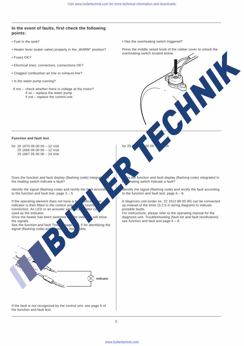
Does the function and fault display (flashing code) integrated inthe heating switch indicate a fault?
Identify the signal (flashing code) and rectify the fault accordingto the function and fault test, page 3 – 5.
If the operating element does not have a fault indicator, anindicator is then fitted to the control unit at the „Test/S”connection. An LED or an acoustic signal transmitter can beused as the indicator.Once the heater has been switched on, the indicator will showthe signals.See the function and fault Test on pages 3 – 5 for identifying thesignal (flashing code) and remedying the trouble.
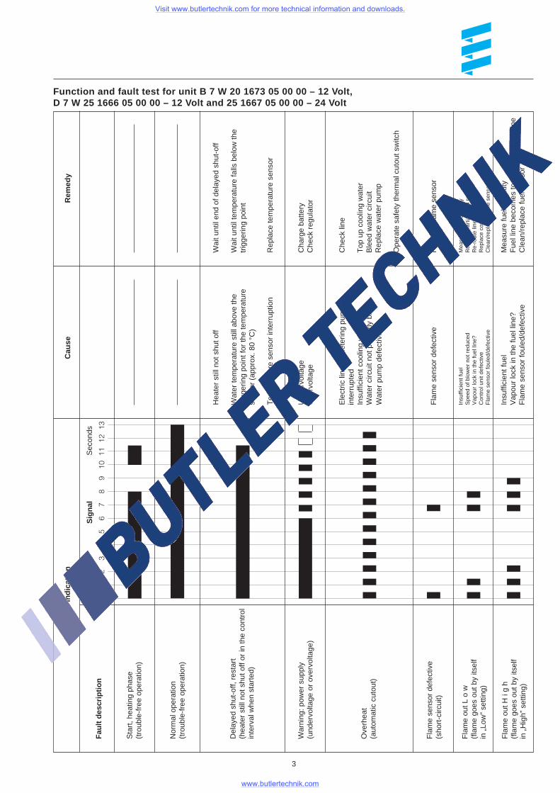
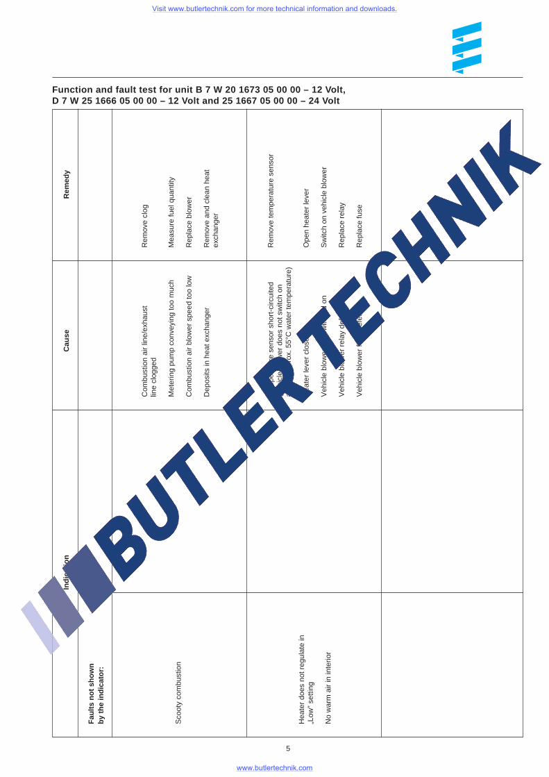
Function and fault test
for 20 1673 05 00 00 – 12 Volt25 1666 05 00 00 – 12 Volt25 1667 05 00 00 – 24 Volt
for 25 1807 05 00 00 – 12 Volt
Does the function and fault display (flashing code) integrated inthe heating switch indicate a fault?
Identify the signal (flashing code) and rectify the fault accordingto the function and fault test, page 6 – 8.
A diagnosis unit (order no. 22 1512 89 00 00) can be connectedup instead of the timer (3.2.5 in wiring diagram) to indicatepossible faults.For instructions, please refer to the operating manual for thediagnosis unit. Troubleshooting (fault list and fault rectification)see function and fault test page 6 – 8.
Test
In the event of faults, first check the followingpoints:
• Fuel in the tank?
• Heater lever (water valve) properly in the „WARM” position?
• Fuses OK?
• Electrical lines, connectors, connections OK?
• Clogged combustion air line or exhaust line?
• Is the water pump running?
If not – check whether there is voltage at the motor?if so – replace the water pumpif not – replace the control unit
2
SwitchPositive
• Has the overheating switch triggered?
Press the middle raised knob of the rubber cover to unlock theoverheating switch located below.
Visit www.butlertechnik.com for more technical information and downloads.
www.butlertechnik.com
01
23
45
67
89
1011
1213
Indi
catio
n
Sec
onds
Sig
nal
Cau
seR
emed
y
Sta
rt, h
eatin
g ph
ase
(tro
uble
-fre
e op
erat
ion)
Nor
mal
ope
ratio
n(t
roub
le-f
ree
oper
atio
n)
Del
ayed
shu
t-of
f, re
star
t(h
eate
r st
ill n
ot s
hut o
ff or
in th
e co
ntro
lin
terv
al w
hen
star
ted)
War
ning
: pow
er s
uppl
y(u
nder
volta
ge o
r ov
ervo
ltage
)
Ove
rhea
t(a
utom
atic
cut
out)
Fla
me
sens
or d
efec
tive
(sho
rt-c
ircui
t)
Fla
me
out L
o w
(fla
me
goes
out
by
itsel
fin
„Lo
w”
setti
ng)
Fla
me
out H
i g
h(f
lam
e go
es o
ut b
y its
elf
in „
Hig
h” s
ettin
g)
Hea
ter
still
not
shu
t off
Wat
er te
mpe
ratu
re s
till a
bove
the
trig
gerin
g po
int f
or th
e te
mpe
ratu
rese
nsor
(ap
prox
. 80
°C)
Tem
pera
ture
sen
sor
inte
rrup
tion
Fla
me
sens
or d
efec
tive
Insu
ffici
ent f
uel
Spe
ed o
f blo
wer
not
red
uced
Vap
our
lock
in th
e fu
el li
ne?
Con
trol
uni
t def
ectiv
eF
lam
e se
nsor
foul
ed/d
efec
tive
Wai
t unt
il en
d of
del
ayed
shu
t-of
f
Wai
t unt
il te
mpe
ratu
re fa
lls b
elow
the
trig
gerin
g po
int
Rep
lace
tem
pera
ture
sen
sor
Che
ck li
ne
Top
up
cool
ing
wat
erB
leed
wat
er c
ircui
tR
epla
ce w
ater
pum
p
Ope
rate
saf
ety
ther
mal
cut
out s
witc
h
Ele
ctric
line
to m
eter
ing
pum
pin
terr
upte
dIn
suffi
cien
t coo
ling
wat
erW
ater
circ
uit n
ot p
rope
rly b
led
Wat
er p
ump
defe
ctiv
e
Rep
lace
flam
e se
nsor
Mea
sure
fuel
qua
ntity
Rep
lace
par
tial-l
oad
resi
stor
Re-
rout
e lin
eR
epla
ce c
ontr
ol u
nit
Cle
an/r
epla
ce fl
ame
sens
or
Fau
lt de
scrip
tion
Function and fault test for unit B 7 W 20 1673 05 00 00 – 12 Volt,D 7 W 25 1666 05 00 00 – 12 Volt and 25 1667 05 00 00 – 24 Volt
3
Mea
sure
fuel
qua
ntity
Fue
l lin
e be
com
es to
o ho
t – r
e-ro
ute
line
Cle
an/r
epla
ce fu
el s
enso
r
Insu
ffici
ent f
uel
Vap
our
lock
in th
e fu
el li
ne?
Fla
me
sens
or fo
uled
/def
ectiv
e
Cha
rge
batte
ryC
heck
reg
ulat
orU
nder
volta
geO
verv
olta
ge
Visit www.butlertechnik.com for more technical information and downloads.
www.butlertechnik.com
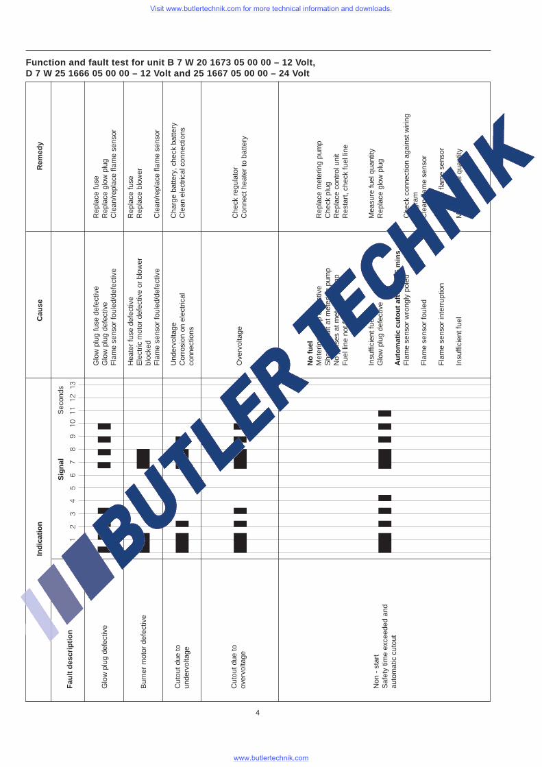
Function and fault test for unit B 7 W 20 1673 05 00 00 – 12 Volt,D 7 W 25 1666 05 00 00 – 12 Volt and 25 1667 05 00 00 – 24 Volt
4
01
23
45
67
89
1011
1213
Indi
catio
n
Sec
onds
Sig
nal
Cau
seR
emed
y
Fau
lt de
scrip
tion
Glo
w p
lug
defe
ctiv
e
Bur
ner
mot
or d
efec
tive
Cut
out d
ue to
unde
rvol
tage
Cut
out d
ue to
over
volta
ge
Non
- s
tart
Saf
ety
time
exce
eded
and
auto
mat
ic c
utou
t
Glo
w p
lug
fuse
def
ectiv
eG
low
plu
g de
fect
ive
Fla
me
sens
or fo
uled
/def
ectiv
e
Hea
ter
fuse
def
ectiv
eE
lect
ric m
otor
def
ectiv
e or
blo
wer
bloc
ked
Fla
me
sens
or fo
uled
/def
ectiv
e
Und
ervo
ltage
Cor
rosi
on o
n el
ectr
ical
conn
ectio
ns
Ove
rvol
tage
No
fuel
Met
erin
g pu
mp
defe
ctiv
eS
hort
-circ
uit a
t met
erin
g pu
mp
No
puls
es a
t met
erin
g pu
mp
Fue
l lin
e no
t fill
ed
Insu
ffici
ent f
uel
Glo
w p
lug
defe
ctiv
e
Aut
omat
ic c
utou
t afte
r 3
– 5
min
s.F
lam
e se
nsor
wro
ngly
pol
ed
Fla
me
sens
or fo
uled
Fla
me
sens
or in
terr
uptio
n
Insu
ffici
ent f
uel
Rep
lace
fuse
Rep
lace
glo
w p
lug
Cle
an/r
epla
ce fl
ame
sens
or
Rep
lace
fuse
Rep
lace
blo
wer
Cle
an/r
epla
ce fl
ame
sens
or
Cha
rge
batte
ry, c
heck
bat
tery
Cle
an e
lect
rical
con
nect
ions
Rep
lace
met
erin
g pu
mp
Che
ck p
lug
Rep
lace
con
trol
uni
tR
esta
rt, c
heck
fuel
line
Mea
sure
fuel
qua
ntity
Rep
lace
glo
w p
lug
Che
ck c
onne
ctio
n ag
ains
t wiri
ngdi
agra
mC
lean
flam
e se
nsor
Rep
lace
flam
e se
nsor
Mea
sure
fuel
qua
ntity
Che
ck r
egul
ator
Con
nect
hea
ter
to b
atte
ry
Visit www.butlertechnik.com for more technical information and downloads.
www.butlertechnik.com
Function and fault test for unit B 7 W 20 1673 05 00 00 – 12 Volt,D 7 W 25 1666 05 00 00 – 12 Volt and 25 1667 05 00 00 – 24 Volt
5
Indi
catio
nC
ause
Rem
edy
Fau
lts n
ot s
how
nby
the
indi
cato
r:
Sco
oty
com
bust
ion
Hea
ter
does
not
reg
ulat
e in
„Low
” se
tting
No
war
m a
ir in
inte
rior
Com
bust
ion
air
line/
exha
ust
line
clog
ged
Met
erin
g pu
mp
conv
eyin
g to
o m
uch
Com
bust
ion
air
blow
er s
peed
too
low
Dep
osits
in h
eat e
xcha
nger
Rem
ove
clog
Mea
sure
fuel
qua
ntity
Rep
lace
blo
wer
Rem
ove
and
clea
n he
atex
chan
ger
Tem
pera
ture
sen
sor
shor
t-ci
rcui
ted
(veh
icle
blo
wer
doe
s no
t sw
itch
onab
ove
appr
ox. 5
5°C
wat
er te
mpe
ratu
re)
Hea
ter
leve
r cl
osed
Veh
icle
blo
wer
not
sw
itche
d on
Veh
icle
blo
wer
rel
ay d
efec
tive
Veh
icle
blo
wer
fuse
def
ectiv
e
Rem
ove
tem
pera
ture
sen
sor
Ope
n he
ater
leve
r
Sw
itch
on v
ehic
le b
low
er
Rep
lace
rel
ay
Rep
lace
fuse
Visit www.butlertechnik.com for more technical information and downloads.
www.butlertechnik.com
6
Fau
lt co
deF
ault
desc
riptio
n0
Indi
catio
n
87
65
43
21
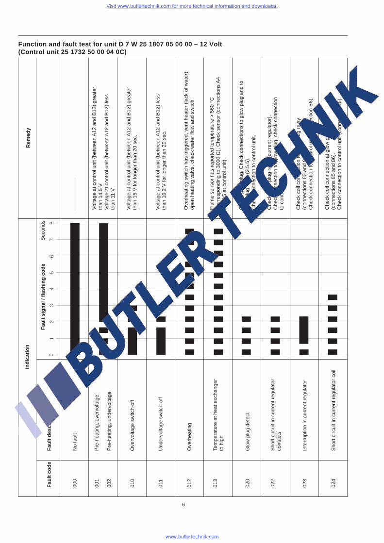
000
No
faul
t
010
Ove
rvol
tage
sw
itch-
off
011
Und
ervo
ltage
sw
itch-
off
001
Pre
-hea
ting,
ove
rvol
tage
002
Pre
-hea
ting,
und
ervo
ltage
012
Ove
rhea
ting
013
Tem
pera
ture
at h
eat e
xcha
nger
to h
igh
020
Glo
w p
lug
defe
ct
022
Sho
rt c
ircui
t in
curr
ent r
egul
ator
cont
acts
023
Inte
rrup
tion
in c
urre
nt r
egul
ator
024
Sho
rt c
ircui
t in
curr
ent r
egul
ator
coi
l
Vol
tage
at c
ontr
ol u
nit (
betw
een
A12
and
B12
) gr
eate
rth
an 1
5 V
for
long
er th
an 2
0 se
c.
Vol
tage
at c
ontr
ol u
nit (
betw
een
A12
and
B12
) le
ssth
an 1
0.2
V fo
r lo
nger
than
20
sec.
Fla
me
sens
or h
as r
epor
ted
tem
pera
ture
> 5
60 °
C(c
orre
spon
ding
to 3
000
Ω).
Che
ck s
enso
r (c
onne
ctio
ns A
4an
d A
5 at
con
trol
uni
t).
Che
ck g
low
plu
g re
lay
(cur
rent
reg
ulat
or).
Che
ck c
onne
ctio
n to
glo
w p
lug,
che
ck c
onne
ctio
nto
con
trol
uni
t.
Che
ck g
low
plu
g. C
heck
con
nect
ions
to g
low
plu
g an
d to
glow
plu
g re
lay
(2.5
.5).
Che
ck c
onne
ctio
n to
con
trol
uni
t.
Che
ck c
oil c
onne
ctio
n to
glo
w p
lug
rela
y(c
onne
ctio
ns 8
5 an
d 86
).C
heck
con
nect
ion
to c
ontr
ol u
nit (
conn
ectio
n B
6).
Che
ck c
oil c
onne
ctio
n at
glo
w p
lug
rela
y(c
onne
ctio
ns 8
5 an
d 86
).C
heck
con
nect
ion
to c
ontr
ol u
nit (
conn
ectio
n B
6).
Rem
edy
Fau
lt si
gnal
/ fla
shin
g co
de
Ove
rhea
ting
switc
h ha
s tr
igge
red,
ven
t hea
ter
(lack
of w
ater
),op
en h
eatin
g va
lve,
che
ck w
ater
flow
and
sw
itch
Sec
onds
Vol
tage
at c
ontr
ol u
nit (
betw
een
A12
and
B12
) gr
eate
rth
an 1
4.5
VV
olta
ge a
t con
trol
uni
t (be
twee
n A
12 a
nd B
12)
less
than
11
V
Function and fault test for unit D 7 W 25 1807 05 00 00 – 12 Volt(Control unit 25 1732 50 00 04 0C)
Visit www.butlertechnik.com for more technical information and downloads.
www.butlertechnik.com
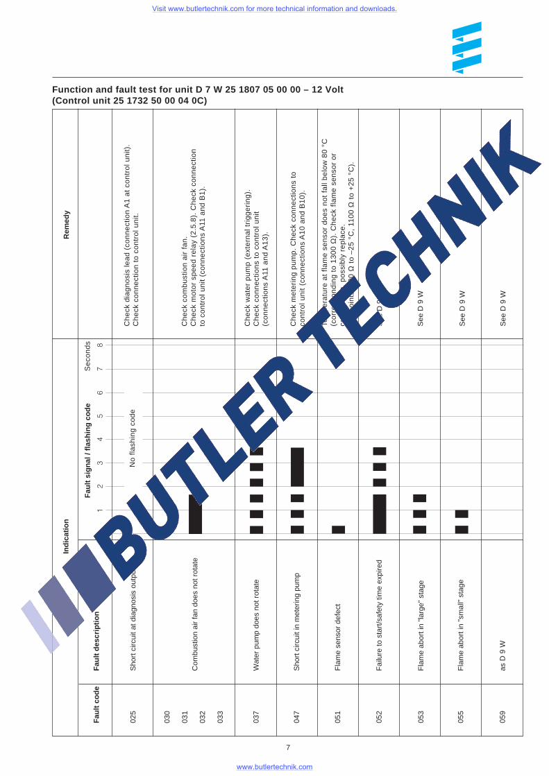
Function and fault test for unit D 7 W 25 1807 05 00 00 – 12 Volt(Control unit 25 1732 50 00 04 0C)
7
Fau
lt co
deF
ault
desc
riptio
n0
Indi
catio
n
87
65
43
21
025
Sho
rt c
ircui
t at d
iagn
osis
out
put
Rem
edy
037
Wat
er p
ump
does
not
rot
ate
047
Sho
rt c
ircui
t in
met
erin
g pu
mp
051
Fla
me
sens
or d
efec
t
053
Fla
me
abor
t in
”larg
e” s
tage
059
as D
9 W
055
Fla
me
abor
t in
”sm
all”
stag
e
030
031
032
033
Ch
eck
wa
ter
pu
mp
(e
xte
rna
l tri
gg
eri
ng
).C
he
ck c
on
ne
ctio
ns
to c
on
tro
l un
it(c
on
ne
ctio
ns
A11
an
d A
13
).
Ch
eck
me
teri
ng
pu
mp
. C
he
ck c
on
ne
ctio
ns
toco
ntr
ol u
nit
(co
nn
ect
ion
s A
10
an
d B
10
).
See
D 9
W
See
D 9
W
See
D 9
W
See
D 9
W
No
fla
shin
g c
od
e
Fau
lt si
gnal
/ fla
shin
g co
deS
eco
nd
s
Com
bust
ion
air
fan
does
not
rot
ate
052
Fai
lure
to s
tart
/saf
ety
time
expi
red
Tem
pe
ratu
re a
t fla
me
se
nso
r d
oe
s n
ot
fall
be
low
80
°C
(co
rre
spo
nd
ing
to
13
00
Ω).
Ch
eck
fla
me
se
nso
r o
rco
mb
ust
ion
, p
oss
ibly
re
pla
ce.
(Se
tpo
ints
: 9
00
Ω t
o –
25
°C
, 11
00
Ω t
o +
25
°C
).
Ch
eck
dia
gn
osi
s le
ad
(co
nn
ect
ion
A1
at
con
tro
l un
it).
Ch
eck
co
nn
ect
ion
to
co
ntr
ol u
nit.
Ch
eck
co
mb
ust
ion
air
fa
n.
Ch
eck
mo
tor
spe
ed
re
lay
(2.5
.8).
Ch
eck
co
nn
ect
ion
to c
on
tro
l un
it (c
on
ne
ctio
ns
A11
an
d B
1).
Visit www.butlertechnik.com for more technical information and downloads.
www.butlertechnik.com
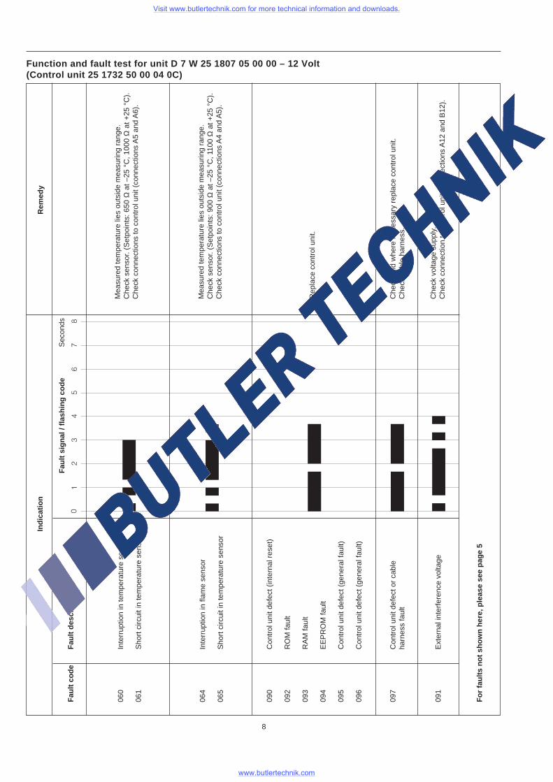
Function and fault test for unit D 7 W 25 1807 05 00 00 – 12 Volt(Control unit 25 1732 50 00 04 0C)
8
Fau
lt co
deF
ault
desc
riptio
n0
Indi
catio
n
87
65
43
21
Rem
edy
060
Inte
rrup
tion
in te
mpe
ratu
re s
enso
r
061
Sho
rt c
ircui
t in
tem
pera
ture
sen
sor
090
Con
trol
uni
t def
ect (
inte
rnal
res
et)
092
RO
M fa
ult
093
RA
M fa
ult
094
EE
PR
OM
faul
t
095
Con
trol
uni
t def
ect (
gene
ral f
ault)
096
Con
trol
uni
t def
ect (
gene
ral f
ault)
097
Con
trol
uni
t def
ect o
r ca
ble
harn
ess
faul
t
For
faul
ts n
ot s
how
n he
re, p
leas
e se
e pa
ge 5
091
Ext
erna
l int
erfe
renc
e vo
ltage
064
Inte
rrup
tion
in fl
ame
sens
or
065
Sho
rt c
ircui
t in
tem
pera
ture
sen
sor
Rep
lace
con
trol
uni
t.
Che
ck a
nd w
here
nec
essa
ry r
epla
ce c
ontr
ol u
nit.
Che
ck c
able
har
ness
.
Mea
sure
d te
mpe
ratu
re li
es o
utsi
de m
easu
ring
rang
e.C
heck
sen
sor.
(Set
poin
ts: 6
50 Ω
at –
25 °
C, 1
000
Ω a
t +25
°C
).C
heck
con
nect
ions
to c
ontr
ol u
nit (
conn
ectio
ns A
5 an
d A
6).
Mea
sure
d te
mpe
ratu
re li
es o
utsi
de m
easu
ring
rang
e.C
heck
sen
sor.
(Set
poin
ts: 9
00 Ω
at –
25 °
C, 1
100
Ω a
t +25
°C
).C
heck
con
nect
ions
to c
ontr
ol u
nit (
conn
ectio
ns A
4 an
d A
5).
Che
ck v
olta
ge s
uppl
y.C
heck
con
nect
ion
to c
ontr
ol u
nit (
conn
ectio
ns A
12 a
nd B
12).
Sec
onds
Fau
lt si
gnal
/ fla
shin
g co
de
Visit www.butlertechnik.com for more technical information and downloads.
www.butlertechnik.com
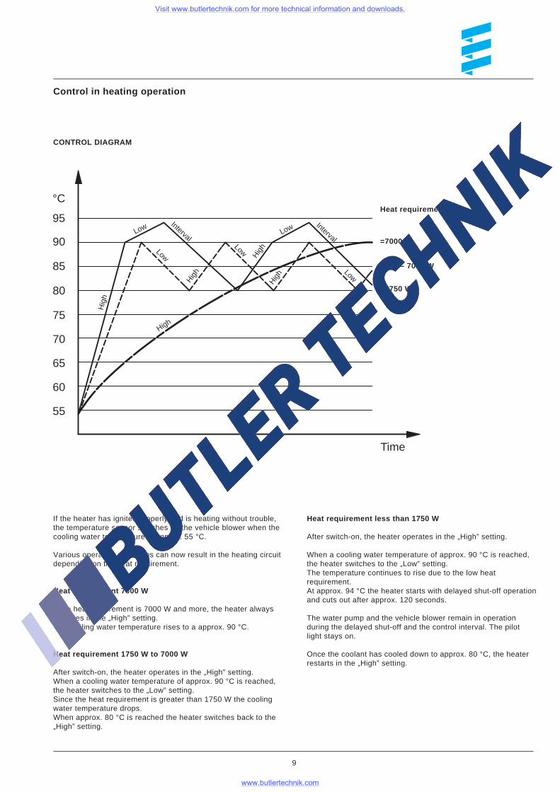
If the heater has ignited properly and is heating without trouble,the temperature sensor switches on the vehicle blower when thecooling water temperature is approx. 55 °C.
Various operating conditions can now result in the heating circuitdepending on the heat requirement.
Heat requirement 7000 W
If the heat requirement is 7000 W and more, the heater alwaysoperates in the „High” setting.The cooling water temperature rises to a approx. 90 °C.
Heat requirement 1750 W to 7000 W
After switch-on, the heater operates in the „High” setting.When a cooling water temperature of approx. 90 °C is reached,the heater switches to the „Low” setting.Since the heat requirement is greater than 1750 W the coolingwater temperature drops.When approx. 80 °C is reached the heater switches back to the„High” setting.
Heat requirement less than 1750 W
After switch-on, the heater operates in the „High” setting.
When a cooling water temperature of approx. 90 °C is reached,the heater switches to the „Low” setting.The temperature continues to rise due to the low heatrequirement.At approx. 94 °C the heater starts with delayed shut-off operationand cuts out after approx. 120 seconds.
The water pump and the vehicle blower remain in operationduring the delayed shut-off and the control interval. The pilotlight stays on.
Once the coolant has cooled down to approx. 80 °C, the heaterrestarts in the „High” setting.
Control in heating operation
9
CONTROL DIAGRAM
<1750 W
1750 – 7000 W
=7000 W
Heat requirement:°C
95
90
85
80
75
70
65
60
55
Time
Hig
h
Low
Low
High
Low
High Low
Low
High
Interval
Interval
High
Visit www.butlertechnik.com for more technical information and downloads.
www.butlertechnik.com
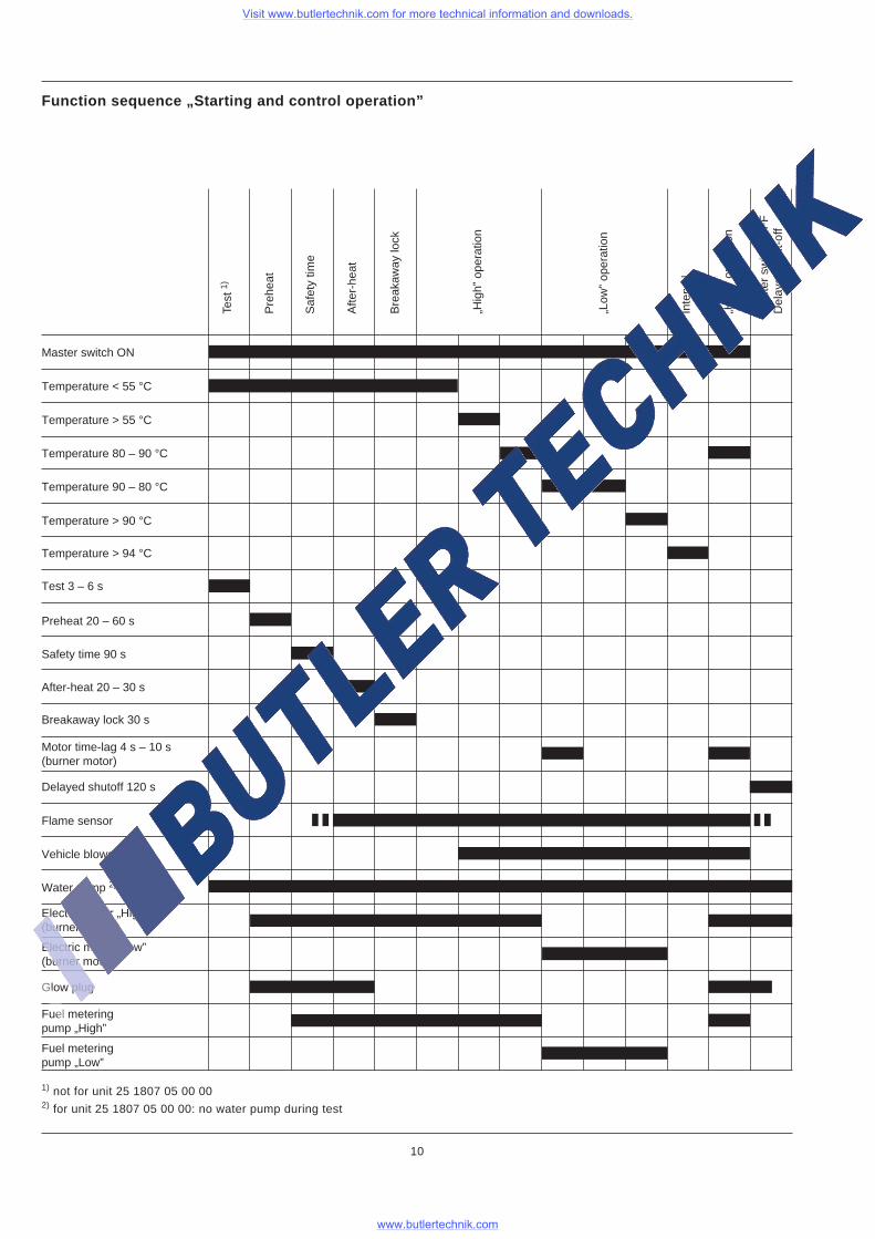
Function sequence „Starting and control operation”
Master switch ON
Temperature < 55 °C
Temperature > 55 °C
Temperature 80 – 90 °C
Temperature 90 – 80 °C
Temperature > 90 °C
Temperature > 94 °C
Test 3 – 6 s
Preheat 20 – 60 s
Safety time 90 s
After-heat 20 – 30 s
Breakaway lock 30 s
Motor time-lag 4 s – 10 s(burner motor)
Flame sensor
Vehicle blower
Electric motor „High”(burner motor)
Water pump 2)
Electric motor „Low”(burner motor)
Glow plug
Fuel meteringpump „High”
Fuel meteringpump „Low”
Test
1)
Pre
heat
Saf
ety
time
Afte
r-he
at
Bre
akaw
ay lo
ck
„Hig
h” o
pera
tion
Inte
rval
„Low
” op
erat
ion
„Hig
h” o
pera
tion
Mas
ter
switc
h O
FF
Del
ayed
shu
t-of
f
10
Delayed shutoff 120 s
1) not for unit 25 1807 05 00 002) for unit 25 1807 05 00 00: no water pump during test
Visit www.butlertechnik.com for more technical information and downloads.
www.butlertechnik.com
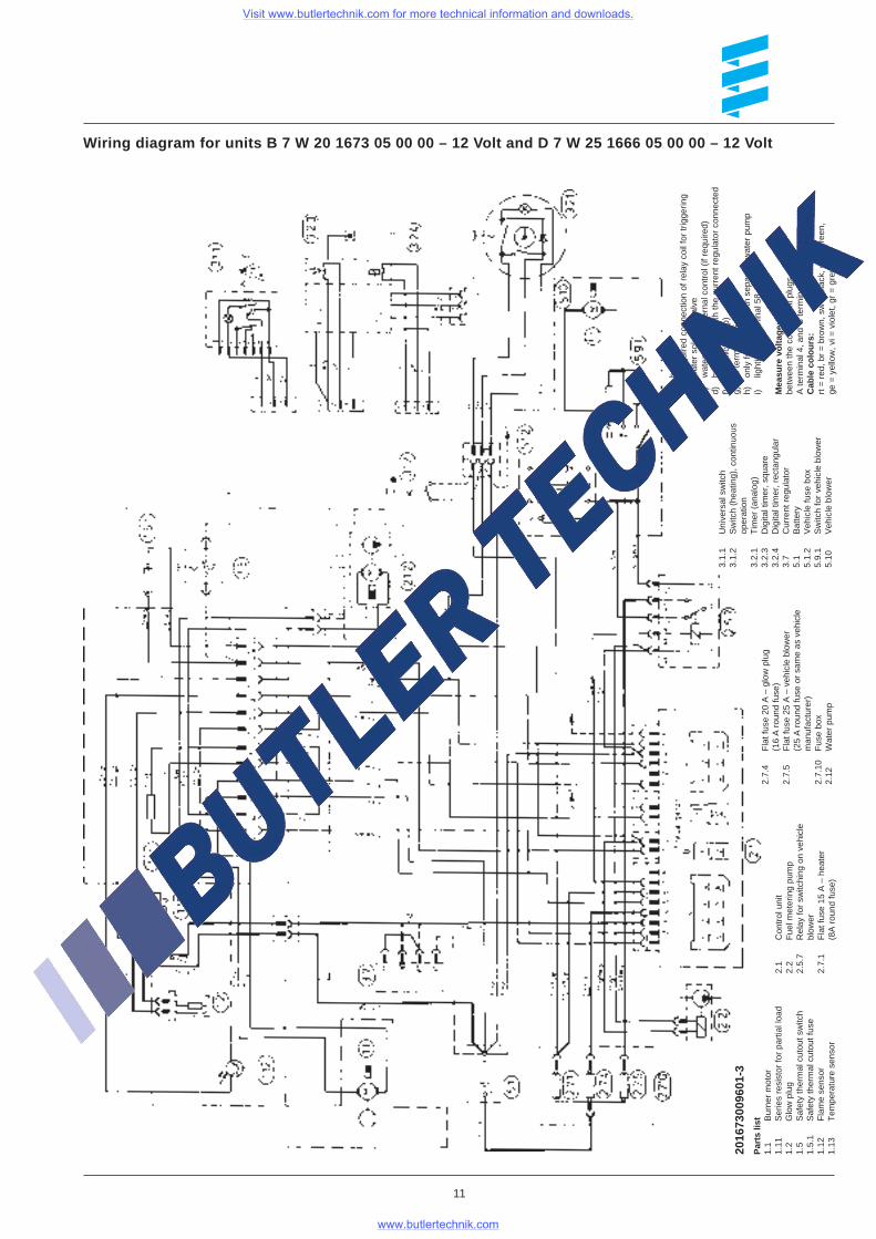
Wiring diagram for units B 7 W 20 1673 05 00 00 – 12 Volt and D 7 W 25 1666 05 00 00 – 12 Volt
Par
ts li
st1.
1B
urne
r m
otor
1.11
Ser
ies
resi
stor
for
part
ial l
oad
1.2
Glo
w p
lug
1.5
Saf
ety
ther
mal
cut
out s
witc
h1.
5.1
Saf
ety
ther
mal
cut
out f
use
1.12
Fla
me
sens
or1.
13T
empe
ratu
re s
enso
r
2.1
Con
trol
uni
t2.
2F
uel m
eter
ing
pum
p2.
5.7
Rel
ay fo
r sw
itchi
ng o
n ve
hicl
ebl
ower
2.7.
1F
lat f
use
15 A
– h
eate
r(8
A r
ound
fuse
)
a)br
eak
b)if
requ
ired
conn
ectio
n of
rel
ay c
oil f
or tr
igge
ring
wat
er s
olen
oid
valv
ec)
wat
er p
ump
exte
rnal
con
trol
(if
requ
ired)
d)br
oken
her
e w
ith th
e cu
rren
t reg
ulat
or c
onne
cted
f)te
st (
wor
ksho
p)g)
to te
rmin
al 1
5h)
only
for
heat
ers
with
sep
arat
e w
ater
pum
pi)
light
ing
to te
rmin
al 5
8
Mea
sure
vol
tage
:be
twee
n th
e co
ntro
l uni
t plu
gs,
A te
rmin
al 4
, and
C te
rmin
al 6
.C
able
col
ours
:rt
= r
ed, b
r =
bro
wn,
sw
= b
lack
, gn
= g
reen
,ge
= y
ello
w, v
i = v
iole
t, gr
= g
rey
2016
7300
9601
-3
11
3.1.
1U
nive
rsal
sw
itch
3.1.
2S
witc
h (h
eatin
g), c
ontin
uous
oper
atio
n3.
2.1
Tim
er (
anal
og)
3.2.
3D
igita
l tim
er, s
quar
e3.
2.4
Dig
ital t
imer
, rec
tang
ular
3.7
Cur
rent
reg
ulat
or5.
1B
atte
ry5.
1.2
Veh
icle
fuse
box
5.9.
1S
witc
h fo
r ve
hicl
e bl
ower
5.10
Veh
icle
blo
wer
2.7.
4F
lat f
use
20 A
– g
low
plu
g(1
6 A
rou
nd fu
se)
2.7.
5F
lat f
use
25 A
– v
ehic
le b
low
er(2
5 A
rou
nd fu
se o
r sa
me
as v
ehic
lem
anuf
actu
rer)
2.7.
10F
use
box
2.12
Wat
er p
ump
Visit www.butlertechnik.com for more technical information and downloads.
www.butlertechnik.com
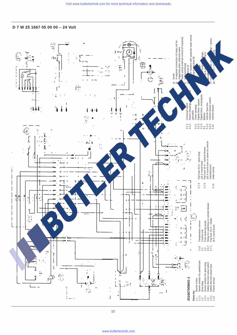
Par
ts li
st1.
1B
urne
r m
otor
1.1.
1S
erie
s re
sist
or fo
r pa
rtia
l loa
d1.
2G
low
plu
g1.
2.1
Ser
ies
resi
stor
for
glow
plu
g1.
5S
afet
y th
erm
al c
utou
t sw
itch
1.5.
1S
afet
y th
erm
al c
utou
t fus
e1.
12F
lam
e se
nsor
1.13
Tem
pera
ture
sen
sor
2.1
Con
trol
uni
t2.
2F
uel m
eter
ing
pum
p2.
5.7
Rel
ay fo
r sw
itchi
ng o
n ve
hicl
e bl
ower
2.7.
1F
lat f
use
15 A
– h
eate
r(8
A r
ound
fuse
)
a)br
eak
b)if
requ
ired
conn
ectio
n of
rel
ay c
oil f
ortr
igge
ring
wat
er s
olen
oid
valv
ec)
wat
er p
ump
exte
rnal
con
trol
(if
requ
ired)
f)te
st (
wor
ksho
p)g)
to te
rmin
al 1
5h)
only
for
heat
ers
with
sep
arat
e w
ater
pum
pi)
light
ing
to te
rmin
al 5
8
Mea
sure
vol
tage
:be
twee
n th
e co
ntro
l uni
t plu
gs,
A te
rmin
al 4
, and
C te
rmin
al 6
Cab
le c
olou
rs:
rt =
red
, br
= b
row
n, s
w =
bla
ck, g
n =
gre
en,
ge =
yel
low
, vi =
vio
let,
gr =
gre
y
2516
6700
9601
-1
D 7 W 25 1667 05 00 00 – 24 Volt
12
3.1.
1U
nive
rsal
sw
itch
3.1.
2S
witc
h (h
eatin
g), c
ontin
uous
oper
atio
n3.
2.1
Tim
er (
anal
og)
3.2.
3D
igita
l tim
er, s
quar
e3.
2.4
Dig
ital t
imer
, rec
tang
ular
5.1
Bat
tery
5.1.
2V
ehic
le fu
se b
ox5.
9.1
Veh
icle
blo
wer
sw
itch
5.10
Veh
icle
blo
wer
2.7.
4F
lat f
use
20 A
– g
low
plu
g(1
6 A
rou
nd fu
se)
2.7.
5F
lat f
use
25 A
– v
ehic
le b
low
er(2
5 A
rou
nd fu
se o
r sa
me
as v
ehic
lem
anuf
actu
rer)
2.12
wat
er p
ump
Visit www.butlertechnik.com for more technical information and downloads.
www.butlertechnik.com
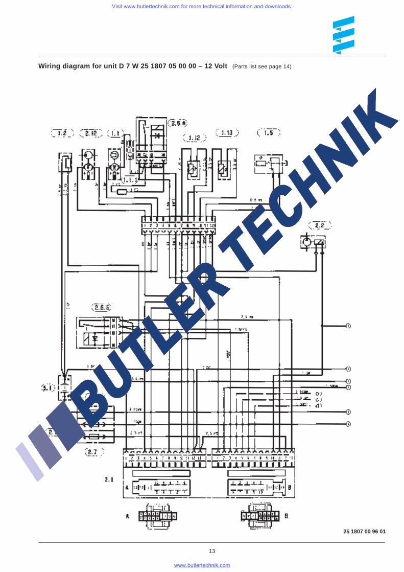
Wiring diagram for unit D 7 W 25 1807 05 00 00 – 12 Volt (Parts list see page 14)
25 1807 00 96 01
13
Visit www.butlertechnik.com for more technical information and downloads.
www.butlertechnik.com
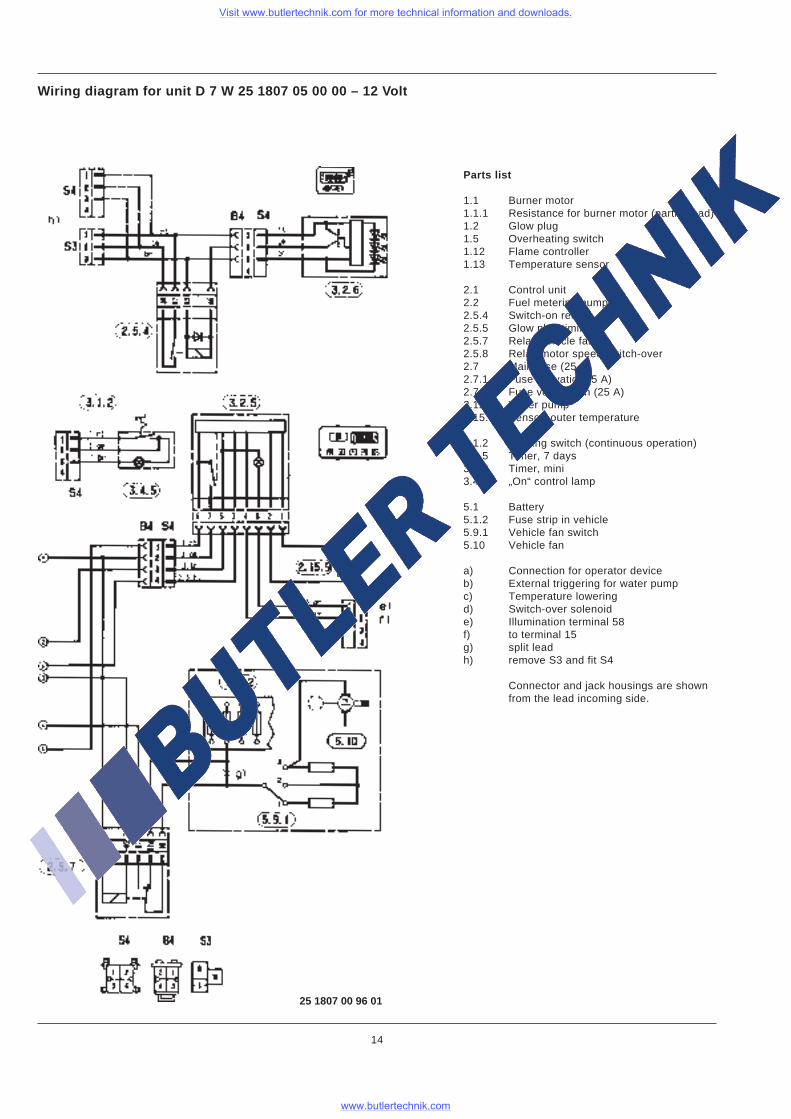
Wiring diagram for unit D 7 W 25 1807 05 00 00 – 12 Volt
25 1807 00 96 01
14
Parts list
1.1 Burner motor1.1.1 Resistance for burner motor (partial load)1.2 Glow plug1.5 Overheating switch1.12 Flame controller1.13 Temperature sensor
2.1 Control unit2.2 Fuel metering pump2.5.4 Switch-on relay2.5.5 Glow plug timing2.5.7 Relay vehicle fan2.5.8 Relay motor speed switch-over2.7 Main fuse (25 A)2.7.1 Fuse activation (5 A)2.7.5 Fuse vehicle fan (25 A)2.12 Water pump2.15.9 Sensor, outer temperature
3.1.2 Heating switch (continuous operation)3.2.5 Timer, 7 days3.2.6 Timer, mini3.4.5 „On“ control lamp
5.1 Battery5.1.2 Fuse strip in vehicle5.9.1 Vehicle fan switch5.10 Vehicle fan
a) Connection for operator deviceb) External triggering for water pumpc) Temperature loweringd) Switch-over solenoide) Illumination terminal 58f) to terminal 15g) split leadh) remove S3 and fit S4
Connector and jack housings are shownfrom the lead incoming side.
Visit www.butlertechnik.com for more technical information and downloads.
www.butlertechnik.com
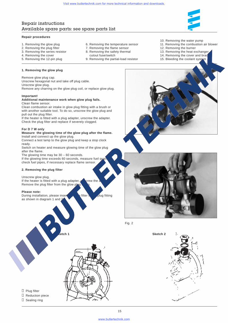
Repair instructionsAvailable spare parts: see spare parts list
Repair procedures
1. Removing the glow plug2. Removing the plug filter3. Removing the series resistor4. Removing the cover5. Removing the 12-pin plug
10. Removing the water pump11. Removing the combustion air blower12. Removing the burner13. Removing the heat exchanger14. Removing the cover and bracket15. Bleeding the coolant system
6. Removing the temperature sensor7. Removing the flame sensor8. Removing the safety thermal cutout fuse/switch9. Removing the partial-load resistor
➀ Plug filter
➁ Reduction piece
➂ Sealing ring
Sketch 2Sketch 1
1. Removing the glow plug
Remove glow plug cap.Unscrew hexagonal nut and take off plug cable.Unscrew glow plug.Remove any charring on the glow plug coil, or replace glow plug.
Important!Additional maintenance work when glow plug fails.Clean flame sensor.Clean combustion air intake in glow plug fitting with a brush orwith another suitable tool. To do so, unscrew the glow plug andpull out the plug filter.If the heater is fitted with a plug adapter, unscrew the adapter.Check the plug filter and replace if severely clogged.
For D 7 W onlyMeasure the glowing time of the glow plug after the flame.Install and connect up the glow plug.Connect a test lamp to the glow plug and keep a stop clockready.Switch on heater and measure glowing time of the glow plugafter the flame.The glowing time may be 30 – 60 seconds.If the glowing time exceeds 60 seconds, measure fuel quantity,check fuel pipes, if necessary replace flame sensor.
2. Removing the plug filter
Unscrew glow plug.If the heater is fitted with a plug adapter, unscrew the adapter.Remove the plug filter from the glow plug fitting.
Please note:During installation, please insert the plug filter in the plug fittingas shown in diagram 1 and 2.
15
Fig. 2
Fig. 1
Visit www.butlertechnik.com for more technical information and downloads.
www.butlertechnik.com
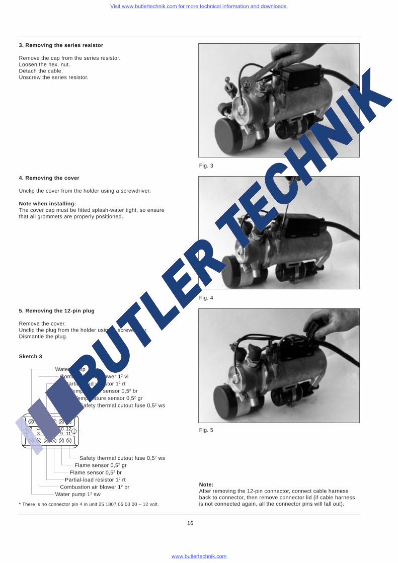
Fig. 5
3. Removing the series resistor
Remove the cap from the series resistor.Loosen the hex. nut.Detach the cable.Unscrew the series resistor.
4. Removing the cover
Unclip the cover from the holder using a screwdriver.
Note when installing:The cover cap must be fitted splash-water tight, so ensurethat all grommets are properly positioned.
5. Removing the 12-pin plug
Remove the cover.Unclip the plug from the holder using a screwdriver.Dismantle the plug.
16
Sketch 3
* There is no connector pin 4 in unit 25 1807 05 00 00 – 12 volt.
Safety thermal cutout fuse 0,52 ws Flame sensor 0,52 gr Flame sensor 0,52 br Partial-load resistor 12 rt Combustion air blower 12 brWater pump 12 sw
Water pump 12 br Combustion air blower 12 vi Partial-load resistor 12 rt Temperature sensor 0,52 br Temperature sensor 0,52 gr Safety thermal cutout fuse 0,52 ws
2 4* 6 8 10 121 3 5 7 9 11
Fig. 3
Fig. 4
Note:After removing the 12-pin connector, connect cable harnessback to connector, then remove connector lid (if cable harnessis not connected again, all the connector pins will fall out).
Visit www.butlertechnik.com for more technical information and downloads.
www.butlertechnik.com
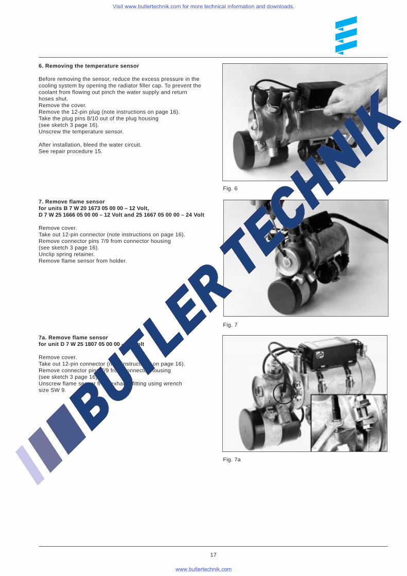
Fig. 7a
6. Removing the temperature sensor
Before removing the sensor, reduce the excess pressure in thecooling system by opening the radiator filler cap. To prevent thecoolant from flowing out pinch the water supply and returnhoses shut.Remove the cover.Remove the 12-pin plug (note instructions on page 16).Take the plug pins 8/10 out of the plug housing(see sketch 3 page 16).Unscrew the temperature sensor.
After installation, bleed the water circuit.See repair procedure 15.
7. Remove flame sensorfor units B 7 W 20 1673 05 00 00 – 12 V olt,D 7 W 25 1666 05 00 00 – 12 Volt and 25 1667 05 00 00 – 24 Volt
Remove cover.Take out 12-pin connector (note instructions on page 16).Remove connector pins 7/9 from connector housing(see sketch 3 page 16).Unclip spring retainer.Remove flame sensor from holder.
7a. Remove flame sensorfor unit D 7 W 25 1807 05 00 00 – 12 Volt
Remove cover.Take out 12-pin connector (note instructions on page 16).Remove connector pins 7/9 from connector housing(see sketch 3 page 16).Unscrew flame sensor from exhaust fitting using wrenchsize SW 9.
17
Fig. 6
Fig. 7
Visit www.butlertechnik.com for more technical information and downloads.
www.butlertechnik.com
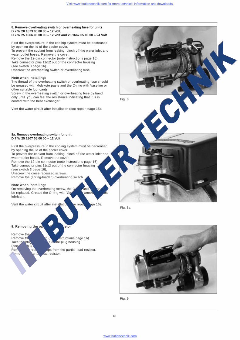
Fig. 8
8. Remove overheating switch or overheating fuse for unitsB 7 W 20 1673 05 00 00 – 12 Volt,D 7 W 25 1666 05 00 00 – 12 Volt and 25 1667 05 00 00 – 24 Volt
First the overpressure in the cooling system must be decreasedby opening the lid of the cooler cover.To prevent the coolant from leaking, pinch off the water inlet andwater outlet hoses. Remove the cover.Remove the 12-pin connector (note instructions page 16).Take connector pins 11/12 out of the connector housing(see sketch 3 page 16).Unscrew the overheating switch or overheating fuse.
Note when installing:The thread of the overheating switch or overheating fuse shouldbe greased with Molykote paste and the O-ring with Vaseline orother suitable lubricants.Screw in the overheating switch or overheating fuse by handonly until you can feel the resistance indicating that it is incontact with the heat exchanger.
Vent the water circuit after installation (see repair stage 15).
8a. Remove overheating switch for unitD 7 W 25 1807 05 00 00 – 12 Volt
First the overpressure in the cooling system must be decreasedby opening the lid of the cooler cover.To prevent the coolant from leaking, pinch off the water inlet andwater outlet hoses. Remove the cover.Remove the 12-pin connector (note instructions page 16).Take connector pins 11/12 out of the connector housing(see sketch 3 page 16).Unscrew the cross-recessed screws.Remove the (spring-loaded) overheating switch.
Note when installing:On removing the overheating screw, the O-ring and seal shouldbe replaced. Grease the O-ring with Vaseline or another suitablelubricant.
Vent the water circuit after installation (see repair stage 15).
Fig. 9
9. Removing the partial-load resistor
Remove the cover.Remove the 12-pin plug (note instructions page 16).Take the plug pins 5/6 out of the plug housing(see sketch 3 page 16).Remove the retaining clips from the partial-load resistor.Remove the partial-load resistor.
18
Fig. 8a
Visit www.butlertechnik.com for more technical information and downloads.
www.butlertechnik.com
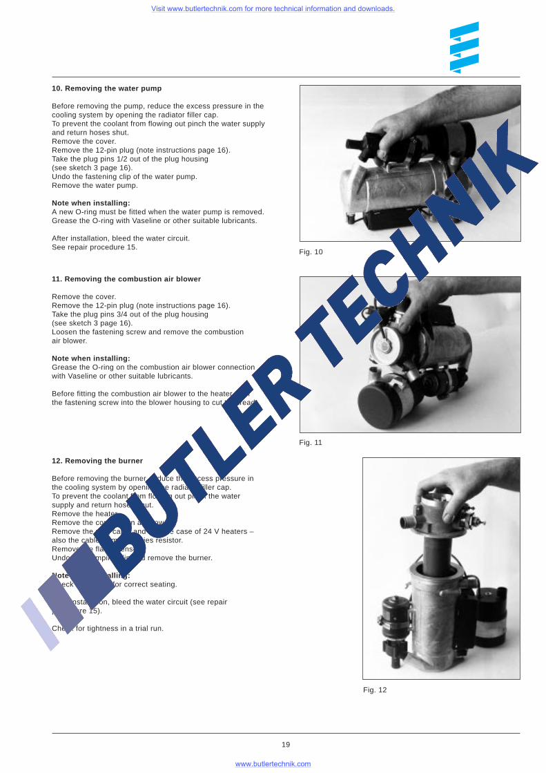
Fig. 10
10. Removing the water pump
Before removing the pump, reduce the excess pressure in thecooling system by opening the radiator filler cap.To prevent the coolant from flowing out pinch the water supplyand return hoses shut.Remove the cover.Remove the 12-pin plug (note instructions page 16).Take the plug pins 1/2 out of the plug housing(see sketch 3 page 16).Undo the fastening clip of the water pump.Remove the water pump.
Note when installing:A new O-ring must be fitted when the water pump is removed.Grease the O-ring with Vaseline or other suitable lubricants.
After installation, bleed the water circuit.See repair procedure 15.
11. Removing the combustion air blower
Remove the cover.Remove the 12-pin plug (note instructions page 16).Take the plug pins 3/4 out of the plug housing(see sketch 3 page 16).Loosen the fastening screw and remove the combustionair blower.
Note when installing:Grease the O-ring on the combustion air blower connectionwith Vaseline or other suitable lubricants.
Before fitting the combustion air blower to the heater, turnthe fastening screw into the blower housing to cut the tread.
Fig. 11
12. Removing the burner
Before removing the burner, reduce the excess pressure inthe cooling system by opening the radiator filler cap.To prevent the coolant from flowing out pinch the watersupply and return hoses shut.Remove the heater.Remove the combustion air blower.Remove the plug cable and – in the case of 24 V heaters –also the cable from the series resistor.Remove the flame sensor.Undo the clamping clip and remove the burner.
Note when installing:Check the O-ring for correct seating.
After installation, bleed the water circuit (see repairprocedure 15).
Check for tightness in a trial run.
19
Fig. 12
Visit www.butlertechnik.com for more technical information and downloads.
www.butlertechnik.com
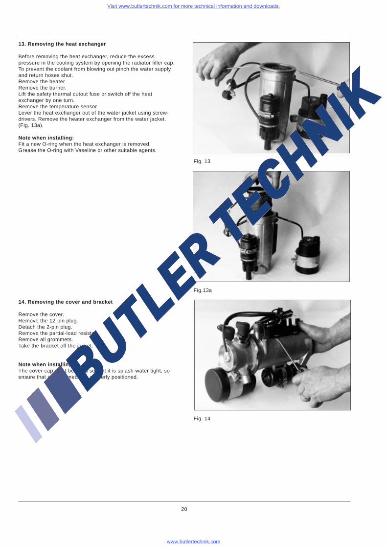
13. Removing the heat exchanger
Before removing the heat exchanger, reduce the excesspressure in the cooling system by opening the radiator filler cap.To prevent the coolant from blowing out pinch the water supplyand return hoses shut.Remove the heater.Remove the burner.Lift the safety thermal cutout fuse or switch off the heatexchanger by one turn.Remove the temperature sensor.Lever the heat exchanger out of the water jacket using screw-drivers. Remove the heater exchanger from the water jacket.(Fig. 13a).
Note when installing:Fit a new O-ring when the heat exchanger is removed.Grease the O-ring with Vaseline or other suitable agents.
14. Removing the cover and bracket
Remove the cover.Remove the 12-pin plug.Detach the 2-pin plug.Remove the partial-load resistor.Remove all grommets.Take the bracket off the jacket.
Note when installing:The cover cap must be fitted so that it is splash-water tight, soensure that all grommets are properly positioned.
20
Fig.13a
Fig. 13
Fig. 14
Visit www.butlertechnik.com for more technical information and downloads.
www.butlertechnik.com
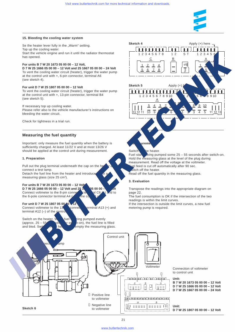
15. Bleeding the cooling water system
Se the heater lever fully in the „Warm” setting.Top up the cooling water.Start the vehicle engine and run it until the radiator thermostathas opened.
For units B 7 W 20 1673 05 00 00 – 12 Volt,D 7 W 25 1666 05 00 00 – 12 Volt and 25 1667 05 00 00 – 24 VoltTo vent the cooling water circuit (heater), trigger the water pumpat the control unit with +, 6-pin connector, terminal A6(see sketch 4).
For unit D 7 W 25 1807 05 00 00 – 12 VoltTo vent the cooling water circuit (heater), trigger the water pumpat the control unit with +, 13-pin connector, terminal B4(see sketch 5).
If necessary top up cooling water.Please refer also to the vehicle manufacturer’s instructions onbleeding the water circuit.
Check for tightness in a trial run.
Measuring the fuel quantity
Important: only measure the fuel quantity when the battery issufficiently charged. At least 11/22 V and at most 13/26 Vshould be applied at the control unit during measurement.
1. Preparation
Pull out the plug terminal underneath the cap on the heater andconnect a test lamp.Detach the fuel line from the heater and introduce it into ameasuring glass (size 25 cm3).
For units B 7 W 20 1673 05 00 00 – 12 Volt,D 7 W 25 1666 05 00 00 – 12 Volt and 25 1667 05 00 00 – 24 VoltConnect voltmeter to the 8-pin connector terminal C6 (+) and tothe 6-pole connector terminal A4 (–) of the control unit.
For unit D 7 W 25 1807 05 00 00 – 12 VoltConnect voltmeter to the 13-pin connector terminal A13 (+) andterminal A12 (–) of the control unit.
Switch on the heater. When fuel is being pumped evenly(approx. 25 – 55 seconds after switch-on), the fuel line is filledand bled. Switch off the heater and empty the measuring glass.
2. Measurement
Switch on the heater.Fuel starts being pumped some 25 – 55 seconds after switch-on.Hold the measuring glass at the level of the plug duringmeasurement. Read off the voltage at the voltmeter.Fuel feed is cut off automatically after 90 sec.Switch off the heater.Read off the fuel quantity in the measuring glass.
3. Evaluation
Transpose the readings into the appropriate diagram onpage 22.The fuel consumption is OK if the intersection of the tworeadings is within the limit curves.If the intersection is outside the limit curves, a new fuelmetering pump is required.
Sketch 6
21
1 2 3 4 5 6 7 8 1 2 1 2 3 4 5 6S T
1 2 3 45 6 7 8
1 2 34 5 6
Test
S
ABC
1 2 3 4 5 6 7 8 9 10A B
1 2 3 4 5 6 7 8 9 10
6 7 8 9 10
1 2 3 4 5 11 12 13678910
12345
111213
Sketch 5
Sketch 4
6 4
46
1213
1213
C B A
A B
Unit:D 7 W 25 1807 05 00 00 – 12 Volt
Unit:B 7 W 20 1673 05 00 00 – 12 VoltD 7 W 25 1666 05 00 00 – 12 VoltD 7 W 25 1667 05 00 00 – 24 Volt
Connection of voltmeterto control unit
➀ ➁
➁➀
➁
Positive lineto voltmeter
➀
Apply (+) here
Apply (+) here
Voltmeter
Control unit
Connect test lamp
Negative lineto voltmeter
Visit www.butlertechnik.com for more technical information and downloads.
www.butlertechnik.com
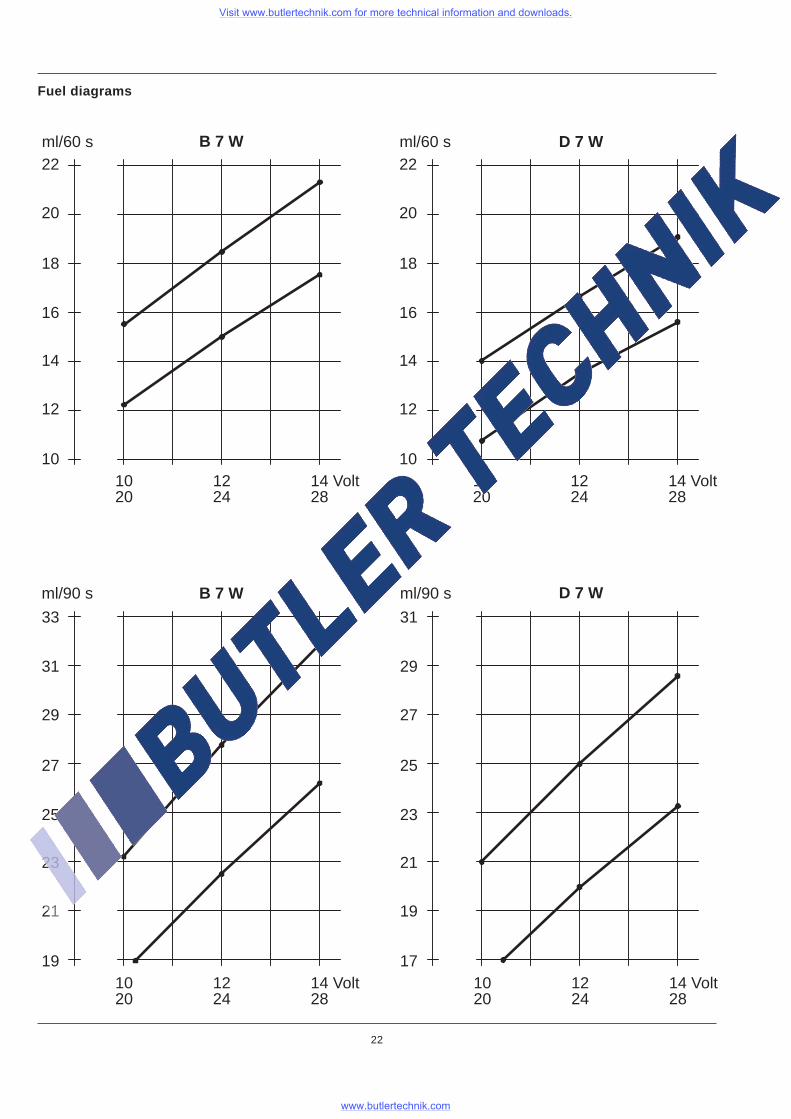
Fuel diagrams
22
B 7 W D 7 W
D 7 WB 7 W
ml/60 s22
20
18
16
14
12
101020
1224
14 Volt28
ml/60 s22
20
18
16
14
12
101020
1224
14 Volt28
ml/90 s
31
29
27
25
23
21
191020
1224
14 Volt28
33
ml/90 s
29
27
25
23
21
19
171020
1224
14 Volt28
31
Visit www.butlertechnik.com for more technical information and downloads.
www.butlertechnik.com