Embed Size (px)
Citation preview

Water Hammer Arresters Standard PDI-WH 201 Revised 2006
Certification Sizing Placement Reference Data
THE PLUMBING AND DRAINAGE INSTITUTE
800 Turnpike Street, Suite 300
North Andover, MA 01845 Phone: (800) 589-8956 Fax: (978) 557-0721
Web: www.pdionline.orgE-mail: [email protected]
©2006 The Plumbing and Drainage Institute

The Standard is not intended to be limiting in any way, but rather is intended to provide a uniform measure of performance by Water Hammer Arresters. The use of this Standard is voluntary and the issuance or existence of this Standard does not in any respect prevent or restrict any member or nonmember of The Plumbing and Drainage Institute from manufacturing or supplying products that do not meet the performance criteria contained in the Standard. The data in this publication are based on information believed to be reliable and are offered in good faith but without guarantee. The Plumbing and Drainage Institute and its member companies assume no responsibility or liability for the use of this Standard. No warranty, express or implied, is made of the information contained in this Standard by The Plumbing and Drainage Institute or by any of its member companies.
FOREWORD
The Plumbing & Drainage Institute is an association of companies engaged in the manufacture of plumbing products. The Institute is dedicated to the advancement of engineering and manufacture of plumbing products.

TABLE OF CONTENTS
WATER HAMMER .....................................4 Definition ...................................................... 4 Reaction ........................................................ 4 Cause ............................................................. 4 Shock Intensity .............................................. 4 Shock Wave .................................................. 5 Water Hammer Noise .................................... 5 System Protection .......................................... 5 Graphic Illustration of a Shock Wave ........... 6 Means of Control ......................................... 7 Air Chamber .................................................. 7 Calculated Air Chambers .............................. 7 Importance of Shock Control ........................ 7 Reference ...................................................... 7 Performance ..................................................9 Example of Failure ........................................ 9 Replenishment of Air .................................... 9 ENGINEERED WATER HAMMER ARRESTERS........................................ 11-12 Engineered Devices...................................... 11 Types ........................................................... 11 Design and Construction ............................. 11 Calculated Air Chamber............................... 11 Performance Comparison Calculated Air Chamber vs.P.D.I. Water Hammer Arrester 11 Performance Test ........................................ 12 Endurance Test ............................................ 12 THE ROLE OF PDI....................................13 CERTIFICATION TESTING EQUIPMENT .......................... 14 Testing Equipment ...................................... 14 Testing Procedure..........................................14 Certification Testing Equipment ...................15 Certificate of Compliance ........................... 16 Use of P.D.I. Certification Mark ................. 16
TESTING FOR THE RIGHT TO USE PDI CERTIFICATION MARK ........................17 Visual Inspection ........................................ 17 Physical Test ................................................ 17 Water Hammer Arrester Certificate ............. 18 SIZING AND PLACEMENT DATA . 19-25 Standardization ........................................... 19 Symbols ...................................................... 19 Single & Multiple Fixture Branch Lines ..... 19 Definition of Fixture-Unit ........................... 19 Sizing and Placement Data .......................... 19 Long Runs of Piping to Equipment.............. 24 Long Runs of Piping ................................... 24 APPENDIX A............................................. 26 Recommended Rules for Sizing the Water Supply System ........................................... 26 Preliminary Information................................26 Demand Load................................................27 Permissible Friction Loss..............................28 Size of Building Supply ................................28 Size of Principal Branches and Riser ............29 General..........................................................29 Example ........................................................29 Sizing Water Systems ........................... 30-35 Estimated Curves for Demand Load.............30 Enlarged Scale Demand Load.......................30 Friction Loss in Head- Smooth Pipe .............31 Friction Loss in Head- Fairly Smooth Pipe...32 Friction Loss in Head- Fairly Rough Pipe ....33 Friction Loss in Head- Rough Pipe...............34 Fixture-Unit Listings.................................... 35 Definitions................................................... 36
3 Standard PDI-WH 201 – Water Hammer Arresters

WATER HAMMERS
The term “Water Hammer” is well known to engineers, contractors, maintenance personnel and other persons engaged in the plumbing and piping industry. Ever since water was first conveyed by a piping system, the destructive forces and hammer-blow sounds, associated with “Water Hammer” have caused annoyances, inconvenience and costly damage. The purpose of this manual is to present an exhaustive study of water hammer and tested methods by which it can be completely controlled.
Definition
Water hammer is the term used to define the destructive forces, pounding noises and vibration which develop in a piping system when a column of non-compressible liquid flowing through a pipe line is stopped abruptly. The tremendous forces generated at the point of stoppage can be compared, in effect, to that of an explosion. Reaction
When water hammer occurs, a high intensity pressure wave travels back through the piping system until it reaches a point of some relief such as a large diameter riser or piping main. The shock wave will then surge
back and forth between the point of relief and the point of impact until the destructive energy is dissipated in the piping system. This violent action accounts for the piping noise and vibration. Cause
The common cause of shock is the quick closing of electrical, pneumatic, spring loaded valves or devices, as well as the quick hand closure of valves or fixture trip. The speed of the valve closure time, especially during the last 15% of valve closure, is directly related to the intensity of the surge pressure. Shock Intensity
Quick valve closure may be defined as a closure equal to or less than 2L seconds.
a Maximum pressure rise will follow. This pressure rise can be calculated by the
following, known as Joukowsky’s formula: pr = wav (p.s.i.)
144g Where pr = pressure rise above flow pressure, p.s.i w = specific weight of liquid, lbs./ft.3 (62.4 water) a = velocity of pressure wave, ft./sec. (4000-4500
average for water) v = change in flow velocity, ft./sec. g = acceleration due to gravity, ft./sec.2 (32.2) STATIC L = length of pipe (ft.) from point of valve closure
to point of relief (see definition of Point of Relief, Page 36) This action will produce an approximate
pressure rise of 60 times the velocity. Engineers generally employ a velocity between 5 and 10 feet per second which may produce a shock
FLOW
pressure of 300-600 p.s.i.SHOCK
Figure 1:
4 Standard PDI-WH 201 – Water Hammer Arresters

Shock Wave
The resultant water hammer shock wave travels back and forth in the piping, between the point of quick closure and the point of relief, at a rate of 4000-4500 feet per second. Graphic illustrations of a shock wave are shown in Fig. 2. In this illustration it will be noted that the shock wave alternately expands and contracts the piping during its occurrence. This is the destructive force which may cause any of the following conditions.
• Ruptured Piping • Leaking Connections • Weakened Connections • Pipe Vibration and Noise • Damaged Valves • Damaged Check Valves • Damaged Water Meters • Damaged Pressure Regulators and
Gauges • Damaged Recording Apparatus • Loosened Pipe Hangers and Supports • Ruptured Tanks and Water Heaters • Premature Failures of Other Equipment
and Devices
Water Hammer Noise
Although noise is generally associated with the occurrence of water hammer it can occur without audible sound. Quick closure always creates some degree of shock - with or without noise. Therefore, the absence of noise does not indicate that water hammer or shock is nonexistent in a water distribution system. System Protection
Water hammer arresters prolong the service life of piping, valves, fittings, trim, equipment, apparatus and other devices which are part of a water distribution system.
5 Standard PDI-WH 201 – Water Hammer Arresters

Figure 2:
6 Standard PDI-WH 201 – Water Hammer Arresters
MEANS OF CONTROL
In order to reduce shock pressure and confine
its action to the section of piping in which it occurs, a suitable means of control must be provided to absorb and dissipate the energy causing the shock. Air or gas is the most effective medium that can be used for this purpose since it is highly compressible.
Air Chamber
For many years the air chamber has been utilized as one means for controlling shock. The unit consists of a capped piece of pipe, the same diameter as the line it serves, and its length ranges between 12” and 24”. The air chamber has been constructed in several different shapes. See Figures 3, 4, 5, 6. Comments
The plain air chambers (Fig. 3 and Fig. 4) are generally placed on the supply lines to fixtures or equipment. A standpipe type of air chamber (Fig. 5) is generally placed on a piping main. A rechargeable type of air chamber (Fig. 6) is generally placed at the end of a branch line or on a piping main.
These air chambers shown in the diagram, are made of pipe and fittings. However, unless such devices are of the correct size and contain a prescribed volume of air, they cannot be regarded as suitable even for the temporary control of shock.
Calculated Air Chambers
In order for an air chamber to adequately control shock, it must be of sufficient proportions and possess a prescribed displacement capacity of entrapped air. If correctly sized, an air chamber may temporarily reduce the maximum shocks occurring in a line to a safe pressure. Importance of Shock Control
Most valves and fittings used in plumbing water distribution systems are designed and constructed for normal maximum rated pressures of 150 P.S.I.G. Therefore, unless an air chamber can reduce shock pressures to some degree less than 150 P.S.I.G., serious damage to the valves, fittings and other components of the piping system may result. The commonly used air chamber, even when correctly sized, only controls shocks temporarily after it is initially installed. Reference
F.M. Dawson and A.A. Kalinske, of the Iowa Institute of Hydraulic Research, in their technical bulletin No. 3 titled “Water Supply Piping For the Plumbing System” indicated the recommended volume of air chambers for varied conditions of pipe size, length of run, flow pressure and velocity. Table 1, based upon information supplied by these authorities, lists examples of air chambers required for several conditions.
Figures 3, 4, 5 & 6:
7 Standard PDI-WH 201 – Water Hammer Arresters

Comment From the examples below, it should be
apparent that excessively large air chambers and fittings are required for the temporary control of
shock. The ordinary, inadequately sized air chambers which are generally installed do not possess the capacity needed even for the temporary control of shock.
Nominal Pipe Diameter
Length of Pipe (Ft.)
Flow Pressure P.S.I.C.
Velocity in Feet Per Sec.
Volume in Cubic inches
Physical Size in inches
1/2" 25 30 10 8 3/4" x 15"1/2" 100 60 10 60 1" x 69.5"3/4" 50 60 5 13 1" x 15"3/4" 200 30 10 108 1-1/4" x 72.5"1" 100 60 5 19 1-1/4" x 12.7"1" 50 30 10 40 1-1/4" x 27"
1-1/4" 50 60 10 110 1-1/2" x 54"1-1/2" 200 30 5 90 2" x 27"1-1/2" 50 60 10 170 2" x 50.5"
2" 100 30 10 329 3" x 44.5"2" 25 60 10 150 2-1/2" x 31"2" 200 60 5 300 3" x 40.5"
Required Air ChamberTABLE I
8 Standard PDI-WH 201 – Water Hammer Arresters
PERFORMANCE
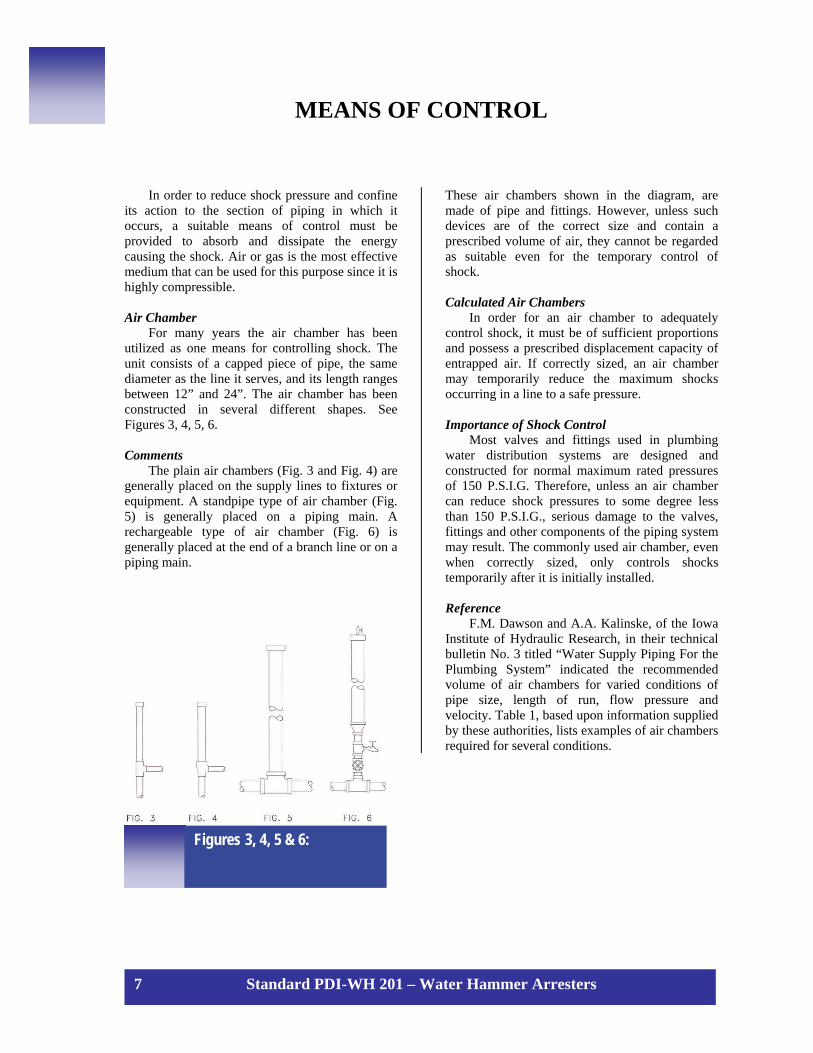
Although a correctly sized air chamber will temporarily control shock to within safe limits of pressure, its performance is effective only while the air chamber retains its initial charge of air. The air, however, is readily lost. See Figures 7, 8, 9, 10.
Comments
As shown, the air charge can be depleted during the flow cycle since water is drawn from all directions. Moreover, the entrapped air is also diminished by turbulence. During this process, the water absorbs the air, and as the unit becomes waterlogged, it loses its ability to absorb shock. Examples of Failure
An air chamber, sized by the Dawson Method, will control shock to limits that do not exceed 150 P.S.I.G. Tests were conducted by the United States Testing Laboratory to determine the elapsed time for an air chamber to exceed 150 P.S.I.G. and in addition, the elapsed time for failure, as evidenced by a violent pounding and vibration in the piping system (see Table II). The conditions of testing were 60 P.S.I.G. flow pressure with a velocity of 10 feet per second.
The tests were run at the rate of 4 valve closures per minute or approximately 1900 valve closures per day. In each case, length of line is 50 feet. Replenishment of Air
It is a popular belief that the air chambers serving a group of fixtures can be replenished with air merely by closing the control valve on the branch line and opening the fixture trip. Actually, it is impossible to replenish the air by this method, as shown by the illustrations in Fig. 11.
Fig. 7 Fig. 8 Fig. 9 Fig. 10
Figures 7, 8, 9 & 10
Exceeded 150 P.S.I.G. Total1 30 1/2" 3/4" 56.7" 1st hour 2nd day2 50 3/4" 1" 58.2" 1st hour 3rd day3 75 1" 1-1/4" 50.0" 1st hour 2nd day4 110 1-1/4" 1-1/2" 54.0" 1st hour 2nd day5 170 1-1/2" 2" 50.5" 1st hour 1st day6 300 2" 3" 40.5" 1st hour 2nd day
Cu. In. CapacityUnit
FailureHeight of Chamber
Dia. of Air ChamberLine Size
Table II: Correctly Sized Air Chambers
9 Standard PDI-WH 201 – Water Hammer Arresters

Comment
As shown in Figures 11(a) & 11(b), the supply piping forms a trap. Therefore it is impossible to drain sufficient water from the piping to allow air to enter. Regardless of how the piping is rearranged, within practical limitations, there is no possible way to introduce air. Only by opening the fixture trip and draining all the branch lines and risers can air be introduced.
It is recognized that a correctly sized air chamber, when initially charged with gas or air at atmospheric pressure, can control water hammer. It has been established the air chamber fails rapidly in an actual installation, (see Table II, page 9). Thus an air chamber cannot be an effective means for the control of shock.
Figure 11: (a) ELEVATION – Showing the arrangement of cold and hot water piping for a group of lavatories. Note the air chambers on the cold and hot water supplies to each lavatory. (b) SECTION – Showing the arrangement of supply piping to lavatory.
10 Standard PDI-WH 201 – Water Hammer Arresters

ENGINEERED WATER HAMMER ARRESTERS Engineered Devices
Engineered devices also use gas or air to control water hammer. The gas or air, however, is permanently sealed in the unit. This feature enables the engineered device to control shock for many years. Types Different styles of engineered devices are on the market. While the basic principle of operation in each unit is somewhat different, each unit is deigned with the permanent cushion of gas or air needed to control shock. Design and Construction
A water hammer arrester must have the capacity to control shock adequately. The construction must be of a quality that will enable the unit to provide many years of dependable service. Calculated Air Chamber
The performance results for a calculated air chamber and an engineered water hammer arrester as obtained in testing are compared in Figs. 12 and 13 respectively. Comments
Conditions of this test: a 50’ length of 1/2” pipe with flow pressures at 60 P.S.I.G. and flow velocity at 10 F.P.S The intended duration of this test was 5000 cycles
with water at ambient temperature. The calculated air chamber was constructed of 3/4” pipe, 56.7” long and capped at one end. This air chamber initially controlled the shock to a limit of just under 150 P.S.I.G. However, this unit permitted a pressure higher than 150 P.S.I.G. within the first 250 cycles of testing and rapidly failed in performance as it reached a pressure in excess of 250 P.S.I.G. after approximately 4400 cycles of testing. Once the pattern of failure had been established, the testing was stopped to avoid needless damage to test equipment. P.D.I. Water Hammer Arrester Comments
A manufactured water hammer arrester certified as a P.D.I. “A” unit was subjected to the same test and conditions as described for the calculated air chamber. This unit controlled the shock to a limit of well under 150 P.S.I.G. for 5000 cycles of testing with water at ambient temperature. The same device was then subjected to an additional 5000 cycles of testing with hot water at 180˚F and still continued to control the surge to well under 150 P.S.I.G. Graphic Illustration
The curves in Fig. 14 clearly indicate the initial, as well as the permanent, effectiveness of a P.D.I. certified water hammer arrester (curve 5) compared to other devices utilized for the prevention of water hammer.
Figure 12: Calculated air chamber
11 Standard PDI-WH 201 – Water Hammer Arresters

Explanation of Fig. 14 (Curves 1 to 5) 1 - Represents a commonly used air chamber. It is
24” in height and is one pipe size larger than the line served. Initially, it controlled the surge at approximately 240 P.S.I.G. but its control gradually becomes less as shown.
2 - Represents a manufactured unit (not certified). Initially it controlled the surge at approximately 210 P.S.I.G. and gradually its control failed as shown. The dotted lines project the estimated rate of failure after 5000 cycles of actual testing.
3 - Represents a manufactured unit (not certified). Initially it controlled the surge at approximately 185 P.S.I.G. and its control continued to fail, as shown. The dotted lines project the estimated rate of failure after 5000 cycles of actual testing.
4 Represents the average performance of
calculated air chambers that initially controlled the surge at approximately 145 psi. but rapidly failed as shown
5 - Represents the performance of a typical P.D.I. unit which initially controlled the surge under 150 P.S.I.G. and maintained this measure of control for 10,000 cycles of testing.
Comments
Although the duration of the above test was 10,000 cycles, P.D.I. units have proven their capability to endure testing under equal conditions involving many hundreds of thousands of cycles of shock, and continues to control the maximum surge to 150 P.S.I.G. or less.
Figure 13: P.D.I. Water hammer arrester
Figure 14: Comparative endurance tests
12 Standard PDI-WH 201 – Water Hammer Arresters

THE ROLE OF PDI
The members of the Plumbing and Draining
Institute have been interested in the cause and control of Water Hammer. Therefore, they engaged in an exhaustive study of this phenomena. The performance of air chambers and engineered arresters was ascertained by extensive testing at a test facility located at the United States Testing Company laboratory in Fairfield, New Jersey. The long term benefit of installing engineered Water Hammer Arresters in place of air chambers is described in the next section.
Recognizing the toll imposed on the test facility by decades of service and the need for improvements, the Institute, after consultation with noted hydraulics authorities, revised the facility to its current configuration, described in Figure 15. Capitalizing on the experience gained by monitoring water hammer arresters in service since the inception of the program, the test facility has undergone a major upgrade to provide optimum performance and total dependability.
The test facility has a computer data acquisition and control system. Computer control allows calibration to be done initially and every 100 endurance cycles and automatically determines exact flow needed. That flow is established by means of a positive displacement gear pump with adjustable speed drive (Fig. 15 item 5). The flow is monitored with a flow meter (Fig. 15 item 26) and the computer automatically adjusts the speed drive each cycle to obtain consistent flow. The flow pressure is established by means of the air pressure in the two 30 gallon pneumatic water tanks (Fig. 15 item 9). The computer measures the flow pressure by means of
the flow transducer (Fig. 15 item 19) and adjusts each cycle by opening the fill or vent valves (Fig. 15 item 10). Valve shut off time is calculated by computer analysis of data each cycle to ensure it is less than the 25 millisecond maximum. The computer measures the temperature of the flow and ensures that the water heater (Fig. 15 item 2) is maintaining the temperature. The ambient temperature tests are done between ambient and at most 10 degrees F over ambient and can be held in such a close range of temperature due to the redesign of the system. Computer control has also made possible the elimination of noise from data signals by means of a 2.5 millisecond moving average of data, an improvement over an unfiltered oscillogram. Developmental testing benefits from having a record of test variables for each test cycle of the endurance test in addition to individual shock dampening graphs and from shut down of testing should this be necessary as soon as prescribed limits are exceeded. It is also possible to provide data from testing in electronic format.
Any manufacturer, whether or not a P.D.I. member, may have their units tested by a qualified independent testing laboratory for certification in accordance with Standard PDI-WH201. For further information on this subject, as well as with reference to use of the Institute’s Certification Mark and participation in its annual visual inspection and physical test program see pages 16 and 17.
13 Standard PDI-WH 201 – Water Hammer Arresters

CERTIFICATION TESTING Introduction
This test procedure has been developed (1) to provide the industry with a standard method of rating water hammer arresters, (2) to establish a minimum standard for design and manufacture of any unit with respect to its serviceability in the water distribution system. The test methods simulate actual service conditions and provide reproducible results so that any engineered water hammer arrester can be tested for compliance with the standard.
Testing Equipment
The test facility is designed to subject the test unit to the full energy imposed by the abrupt stoppage of a 50 foot column of water. The water is flowing in a standard schedule 40 steel pipe exerting a total pressure not to exceed 250 P.S.I.G. for the AA size, and 400 P.S.I.G. for sizes A through F. This arrangement is shown in Figure 15. In order to insure reproducible test results, the following tolerances must be maintained: 1. Surge valve (22) - flow termination not to
exceed 25 milliseconds 2. Flow pressure +/-0.5 P.S.I.G. 3. Total pressure +/-10 P.S.I.G.( surge plus
flow). 4. Pressure transducer smallest incremental
reading 2 P.S.I.G.
Testing Procedure Seven categories have been established to
cover the normal range of sizes required to protect the water distribution system of any building. Table III lists these sizes together with the corresponding test conditions under which each must qualify.
Each unit to be tested shall be installed in the test facility, item 21 of Figure 15, and shall use the corresponding sized test pipe (16). The motorized ball valve (20) shall be moved to the closed position and the pump energized to fill the system with water and purged of air. The test pipe shall be fully supported to avoid high spots where air may be trapped. Pressure gages, valves, and fittings must be purged of air. The test unit is then filled with water in the inverted position. In test units containing an orifice, the fill tube must be inserted in the orifice to eliminate the possibility of trapping air in the bellows convolutions. The filled inverted unit is then capped with a thin plate and, with the plate held firmly in place, rotated to the normally installed position and placed on the brimming ball valve fitting. The plate is slipped out from its position between the test unit and the ball valve as the test unit is threaded into the ball valve and secured in place. The test conditions are then established.
P.D.I. Size
Pipe Size
Pipe Length
(ft.)
*Total Pressure - Flow + Surge Less Arrester
(P.S.I.G.)
*Max. Reduced Pressure Flow + Surge with Arrester (P.S.I.G.)
AA 1/2" 50 250 160A 1/2" 50 400 150B 3/4" 50 400 150C 1" 50 400 150D 1-1/4" 50 400 150E 1-1/2" 50 400 150F 2" 50 400 150
TABLE III
*The total pressure and maximum reduced pressure shall be defined as the highest of any 2.5 millisecond average pressure measured during the calibration and testing procedure.
The test unit will have passed the endurance test by comparing 10,000 cycles without the reduced pressure exceeding 160 P.S.I.G. for any 10 consecutive cycles at any time during the endurance test.
14 Standard PDI-WH 201 – Water Hammer Arresters

CERTIFICATION TESTING EQUIPMENT
LISTING OF EQUIPMENT
1 – Sump tank 4’ dia. x 4½’ high – 450 gallon 2 – Water heater 3 – Shutoff valves 5 – Gear pump with adjustable speed drive, computer
controlled 6 – Pressure relief valve 7 – 2” pipe 8 – Two 2” gate valves for inlet to pneumatic tanks 9 – Two 30 gal. pneumatic water tanks (12” dia.),
one with 24” sight glass 10 – ½” air line with automatic fill & vent valves 12 – 3” gate valves 13 – 10” return bend 36” between centers
14 – Float vent air bleed installed at top of return bend 15 – 2” ball valve 16 – Test length steel pipe (sizes 2”, 1½”, 1¼”, 1”,
¾” and ½” to fit between A1 and A2 17 – Dynamic pressure transducer, Kistler Model
212B3 Piezotron 18 – Solenoid valve 19 – Static pressure transducer 20 – Actuated ball valve, same size as test pipe 21 – Water hammer arrester test unit 22 – 1½” pneumatically actuated surge valve 23 – 2” solenoid valve 24 – 2” metering valve 25 – ½” metering valve 26 – Flow transducer 27 – 2” pipe line
Figure 15:
15 Standard PDI-WH 201 – Water Hammer Arresters
The pump (5) is energized to circulate water through the system with the solenoid valve (18) open to the transducer (19). The required flow rate and flow pressure (60 P.S.I.G.) are established and maintained by a computerized data acquisition and control system. This system also operates the quick closing hydraulic surge valve (22) and measures the magnitude of the resulting shock wave. Ten (10) calibration cycles will be conducted initially with valve (20) closed in order to ascertain that a surge pressure of 340+/-10 P.S.I.G. for sizes A through F (or 190+/-10 P.S.I.G. for size AA) at a flow pressure of 60+/-0.5P.S.I.G. is obtained. At least three (3) such calibration cycles shall be conducted after every 100 cycles. The test unit is then exposed to the cyclic test by opening valve (20) and isolating the flow transducer (19) by closing valve (18)
The unit shall be subjected to 5,000 cycles of shock testing with water at ambient temperature. The same unit shall be subjected to an additional 5,000 cycles of shock testing with water at 180 degrees F. minimum. The total pressure shall be recorded after each cycle. The unit shall be certified if no ten consecutive cycles exceed 160 P.S.I.G. total pressure. Certificate of Compliance
A certificate of compliance may be issued by a qualified independent testing laboratory
for a water hammer arrester only after the unit has been successfully tested for performance and endurance in the manner prescribed herein. The certificate must be the equivalent of the example shown in Fig. 16. The description on the certificate shall be adequate for identification of the product. Upon further certification by the manufacturer that its current production units which are of the same size, type or model as the unit tested are identical thereto then such manufacturer may represent such units were “Tested in ————(year) and complied with PDI-WH-201” so long as such units are in fact demonstrated, upon proper demand, to be identical in the relevant respects considered in PDI WH-201 as of the year the representative unit was tested but may not claim such units to be certified by the Plumbing and Drainage Institute or use its Certification Mark. Use of P.D.I. Certification Mark
Only water hammer arresters which are certified by the manufacturer as being identical in the relevant respects considered in P.D.I. WH-201 to the unit tested and certified as above detailed by an independent laboratory approved by the Institute may bear the Institute’s Certification Mark as exemplified in Fig. 16A provided such manufacturer also executes the Institute’s current standard Certification Mark License Agreement.
Figure 16A:
16 Standard PDI-WH 201 – Water Hammer Arresters

TESTING FOR THE RIGHT TO USE PDI CERTIFICATION MARK
In an effort to assure continued compliance with Standard PDI-WH201, a program has been established. Annual Visual Inspection - Physical Test Program
Within three years from the date of original certification and yearly thereafter, each manufacturer must resubmit two units, size to be designated by the Institute, along with a complete set of current detailed drawings, to the qualified independent testing laboratory approved by the Institute which previously tested the units, for a visual inspection and a physical test to be made as follows: Visual Inspection
One unit must be cut in half on a bandsaw or other means so that the interior can be observed and compared to the drawings in respect to physical size and shape. The materials must be observed in respect to material specifications. If
materials do not appear to be the same as specified, further analytical tests must be conducted. Physical Test
The other unit must be given a performance test according to procedures outlined in Standard PDI-WH201. 1. The inspected and tested units, and their
detailed drawings must be properly labeled and retained for future reference and comparisons.
2. Any discrepancies found must be referred to the Executive Secretary of the PDI who, in turn, shall notify the manufacturer and the PDI engineers for evaluation and recommendations for action to be taken by the Institute.
3. The manufacturer must obtain a Statement of Compliance that the water hammer arresters met all of the requirements outlined in the Standard PDIWH201 for the Annual Visual Inspection - Physical Test Program.
17 Standard PDI-WH 201 – Water Hammer Arresters

(Name of Independent Testing Laboratory)
(Street, City, State and Zip Code)
WATER HAMMER ARRESTER CERTIFICATE SIZE AA THRU F
This is to certify that a production Water Hammer Arrester, Model No. _______, manufactured by, or for ___________________, which conforms to the drawings and dimensions illustrated herein, has been tested by us as of this date in accordance with the testing procedures established by the Plumbing and Drainage Institute, in P.D.I. Standard WH-201, for size _______ Water Hammer Arresters. We further certify that when such arrester was tested on a ______ inch pipe line of fifty feet effective length, flow pressures of 60 P.S.I.G. and surge pressure of 340 P.S.I.G. (400 P.S.I.G. maximum total pressure) such arrester limited the total pressure created by sudden valve closure to 160 P.S.I.G. maximum which is the acceptable limit to such Standard. The results of tests conducted on this unit are applicable to this unit only. Use of this data and/or reference to the Plumbing Drainage Institute or the above named laboratory in connection with purported certification by any other means than testing to the applicable standard without the consent of the Plumbing Drainage Institute will constitute a breach of the relevant certification Mark License Agreement with the Plumbing Drainage Institute.
(Drawing, dimensions and description) Subscribed and swore to (or affirmed) The statements made herein are certified before me at to be true and correct: _______________________________ Name ___________________________ this ____ day of ___________, 20____ Title ____________________________ Notary Public __________________ Date ____________________________ My commission expires __________ Test No. _________________________
Figure 16:
18 Standard PDI-WH 201 – Water Hammer Arresters

SIZING AND PLACEMENT DATA
During the past years, various methods have been devised for the sizing of water hammer arresters. These varied sizing methods have created confusion among engineers, contractors and other persons engaged in the plumbing industry. Standardization
The members of the Plumbing and Drainage Institute were aware of the difficulties encountered in the application of the different sizing methods. Therefore, they engaged in a research and testing program with the intention of producing one standardized method of sizing and placement - a method which would be of benefit to the entire plumbing industry. The final results are listed in this manual. Symbols
Before the subject of a proposed sizing method can be explained it is first necessary to devise a code of symbols for the 7 different sized units required for average plumbing systems. Each unit must have a different size and capacity to control shock in piping systems of varied size and scope. The following symbol listing has been devised to denote the range in sizes for water hammer arresters, “AA” is the smallest sized unit - “F” represents the largest unit.
P.D.I. Symbols: AA-A-B-C-D-E-F Comment
The P.D.I. symbols established above correspond to those units covered by the certification testing program and shall be used with all data on sizing and placement presented in this manual. Sizing and Placement Data Single and Multiple Fixture Branch Lines
Single and Multiple Fixture Branch Lines A method of sizing, based upon fixture units has been established as most appropriate because it is quick, accurate and well known. Most engineers use fixture-units for sizing water distribution systems.
Definition of Fixture-Unit The National Plumbing Code offers this
definition: “A fixture-unit is a quantity in terms of which the load producing effects on the plumbing system of different kinds of plumbing fixtures are expressed on some arbitrarily chosen scale.” The following fixture-unit table is based upon information offered in the National Plumbing Code.
“Public” fixtures, are those found in public comfort stations, general toilet rooms, office buildings, and other buildings in which each fixture is open and accessible for use at all times. “Private” fixtures are those in residential areas not freely accessible such as in private homes, residential apartments, hotel guest rooms, private rooms or apartments in residential hotels or dormitories, and the like. Notes
The fixture-unit values shown in the cold and hot water columns of Table IV are utilized in the sizing of water hammer arresters. Additional information on varied types of fixtures and their assigned fixture-unit values are contained in the appendix at the back of this standard. Comment
These are the basic fixture-unit data which most engineers utilize to size their water distribution systems. These data can be used in the sizing and placement of engineered water hammer arresters at the same time that the piping systems are sized. Sizing and Placement Data
In most installations where there are several fixtures, usually only one fixture valve at a time will be closed. Nevertheless, occasionally two or more fixture valves could be closed at the same instant. Table V, on sizing and selection, takes into consideration all design factors including simultaneous usage, pipe size, length, flow pressure and velocity. Table V, therefore, provides an easy, accurate method of determining the proper sized water hammer arrester for each multiple fixture branch line, and automatically provides for all factors which must be considered or otherwise calculated.
19 Standard PDI-WH 201 – Water Hammer Arresters

When the weight in “fixture-units” for cold and hot water branch lines serving a group of fixtures has been determined, this data can be applied to Table V.
Note: Ideally the flow pressure in branch lines serving fixtures should never exceed 55 p.s.i.g. Pressure reducing valves should be installed to maintain proper pressure. When, however, the
flow pressure exceeds 65 p.s.i.g., the next larger size water hammer arrester should be selected.
If the Fixture-unit total has a ½ fraction, it is to be rounded up to the next larger, or whole number. Thus, if the total is 11½ fixture-units, change it to 12 fixture-units.
Total C.W. H.W. Total C.W. H.W.Water Closet 1.66 PF Flush Valve 8 8 - 5 5 -Water Closet 1.66 PF Flush Tank 5 5 - 2.5 2.5 -
Pedestal Urinal 1.06 PF Flush Valve 4 4 - - - -Stall or Water Urinal Flush Valve 1.06 PF 4 4 - - - -Stall or Water Urinal Flush Tank 1.06 PF 2 2 - - - -
Lavatory Faucet 2 1-½ 1-½ 1 1 1Bathtub Faucet 4 2 3 2 1-½ 1-½
Shower Head Mixing Valve 4 2 3 2 1 2Bathroom Group Flush Valve Closet - - - 8 8 3Bathroom Group Flush Tank Closet - - - 6 6 3Separate Shower Mixing Valve - - - 2 1 2Service Sink Faucet 3 3 3 - - -Laundry Tubs (1-3) Faucet - - - 3 3 3Combination Fixture Faucet - - - 3 3 3
TABLE IV
FixtureType of Supply
Control
Weight in Fixture - UnitsPublic Private
P.D.I. Units AA A B C D E FFIXTURE-UNITS 1-3 1-11 12-32 33-60 61-113 114-154 155-330
TABLE V Examples
Cold Water Branch 2 W.C. at 10 F.U. ...ea.=20 Hot Water Branch 2 Ur. At 5 F.U. ...ea.=10 4 Lav. at 1½ F.U.ea.= 6
Example 1:
Cold Water Branch 2 W.C. at 10 F.U. ...ea.=20 Hot Water Branch 4 Lav. at 1½ F.U. ...ea.= 6 4 Lav. at 1½ F.U. ea.= 6 Total 26 Total 6 Select P.D.I. “B” Unit Select P.D.I. “A” Unit
4 Lav. at 1½ F.U. ...ea.= 6 Total 6 Total 36 Select P.D.I. “C” Unit Select P.D.I. “A” Unit
Example 2:
20 Standard PDI-WH 201 – Water Hammer Arresters

Table V will permit engineers and contractors to select the proper water hammer arrester for each application. The following examples show the relative ease with which sizing can be accomplished using Tables IV and V.
It is relatively easy to select the proper sized water hammer arrester for a multiple fixture branch. Fig. 17 represents a typical riser diagram of the type that an engineer may include with his set of drawings.
When sizing the cold and hot water branch lines, it is usual practice to obtain the total number of fixture-units on each branch line. This information is then applied to sizing charts to determine the required size of the branch lines.
The proper sized water hammer arresters can be selected once the total of fixture-units for a cold or hot water branch line is known. It is only necessary to apply the fixture-units to Table V and select the appropriate water hammer arrester.
It is suggested that the engineers employ P.D.I. symbols for his riser diagrams, as shown in Figure 17. This practice will enable manufacturers to furnish the correct units.
It has been established that the preferred location for the water hammer arrester is at the end of the branch line between the last two fixtures served. This location is shown in Fig. 18.
Figure 17:
21 Standard PDI-WH 201 – Water Hammer Arresters

The location of the water hammer arresters shown in Fig. 18 applies to branch lines that do not exceed 20’ in length, from the start of the horizontal branch line to the last fixture supply on this branch line. When the branch line exceeds the
20’ length, an additional water hammer arrester should be used. This practice is best defined by two rules which have been established to cover the placement of water hammer arresters. These rules are explained below.
Figure 18: Illustration
RR RR
EXPLANATION – Fixture – unit sizing Table V is used to select the required P.D.I. unit. See example EXPLANATION – Fixture – unit sizing Table V is used to select the required P.D.I.
2
ULE 1 ule 1, covers multiple fixture branch lines which do not exceed 20’ in length.
ULE 2 ule 2, covers multiple fixture branch lines which do exceed 20’ in length
unit. The sum of the F.U. ratings of units X and Y shall be equal to or greater than the demand of the branches. See example
Figure 19: Illustration
EXAMPLE OF RULE 1 EXAMPLE OF RULE 2
C.W. = 26 F.U. Needs – P.D.I. “B” Unit H.W. = 6 F.U. Needs – P.D.I. “A” Unit C.W. = 70 F.U. Needs – P.D.I. “D” Unit
Examples of Rule 1:
2 Standard PDI-WH 201 – Water Hammer Arresters

EXAMPLE OF RULE 2 Point of Relief
C.W. = 52 F.U. Needs two P.D.I. “B” Units H.W. = 12 F.U. Needs two P.D.I. “A” Units C.W. = 90 F.U. Needs one P.D.I. “C” Unit and one P.D.I. “B” Unit
Examples of Rule 2:
EXAMPLE OF RULE 1 AND 2
Figure 20: Note: There are practical limits concerning the overall length of a branch line. In a remote instance where a very long line branch line is involved, the general supply is generally fed to some mid-point or other location on the branch line as shown.
Figure 21:
23 Standard PDI-WH 201 – Water Hammer Arresters

Long Runs of Piping to Equipment
The majority of sizing and selection applications will involve single and multiple fixture branch lines. These are easily handled with Table V. The remainder of applications involve individual runs of piping to a remote item of equipment. The properly sized water hammer arresters for such applications can be determined by Table VI and Table VI-A.
Note: Ideally the flow pressure in branch lines serving fixtures should never exceed 55 p.s.i.g. Pressure reducing valves should be installed to maintain proper pressure. When, however, flow pressures of 65 to 85 p.s.i.g. are used, the next larger size water hammer arrester should be selected. Refer to Table VI-A. The recommendations for sizing and placement of arresters are based on experience of the industry.
Long Runs of Piping
When long runs of piping are employed to serve a remote item of equipment, the water hammer arrester should be located as close as possible to the point of quick closure. At this location, the water hammer arrester will control the developed energy and prevent the shock wave from surging through the piping system. A typical example of placement is given in Fig. 21.
EXAMPLES, defining the sizing and placement of water hammer arresters for single fixture and equipment branch lines are illustrated in Figures 22-26. For the sake of clarity, control valves, vacuum breakers and other necessary devices have been omitted in the illustrations.
Length of Pipe 1/2" 3/4" 1" 1-1/4" 1-1/2" 2'"25 A A B C D E50 A B C D E F75 B C D AE F EF100 C D E F CF FF125 C D F AF EF EFF150 D E F DF FF FFF
Nominal Pipe Diameter
WATER PRESSURES UP TO 65 P.S.I.G.P.D.I. WATER HAMMER ARRESTERS
TABLE VI
Length of Pipe 1/2" 3/4" 1" 1-1/4" 1-1/2" 2'"25 B B C D E F50 B C D E F CF75 C D E F CF FF100 D E F CF EF EFF125 D E CF DF FF BFFF150 E F CF FF DFF FFFF
Nominal Pipe Diameter
WATER PRESSURES 65 P.S.I.G. TO 85 P.S.I.G.P.D.I. WATER HAMMER ARRESTERS
TABLE VI-A
24 Standard PDI-WH 201 – Water Hammer Arresters

CPLFVR
CPL
CPLFVR
onditions ipe size.................= 1” ength of run .........= 92 feet lowing pressure ...= 55 P.S.I.G. elocity .................= 8 F.P.S. ecommendation...= P.D.I. “E” unit
Installed as shown
FVRFigure 22:
Figure 24:
CPLFVR
Figure 25:
25 Standard PDI-WH 201 –
onditions ipe size.................= 2” ength of run.........= 98 feet lowing pressure ...= 60 P.S.I.G. elocity .................= 10 F.P.S. ecommendation...= Two P.D.I. “F” units Installed as shown
Figure 23:
onditions ipe size.................= ¾” ength of run .........= 75 feet lowing pressure ...= 50 P.S.I.G. elocity .................= 6 F.P.S. ecommendation...= Two P.D.I. “C” units Installed as
shown
CPLFV
onditions ipe size.................= 1¼” ength of run.........= 100 feet lowing pressure ...= 53 P.S.I.G. elocity .................= 8 F.P.S. ecommendation...= P.D.I. “F” unit
Installed as shown
RWa
onditions ipe size.................= 1” ength of run.........= 50 feet lowing pressure ...= 45 P.S.I.G. elocity .................= 8 F.P.S. ecommendation...= Two P.D.I. “C” units Installed as shown
Figure 26:
ter Hammer Arresters
APPENDIX A RECOMMENDED RULES FOR SIZING THE WATER
SUPPLY SYSTEM
Because of the variable conditions encountered it is impractical to lay down definite detailed rules of procedure for determining the sizes of water supply pipes in an appendix which must necessarily be limited in length. For a more adequate understanding of the problems involved, the reader is referred to Water-Distributing Systems for Buildings, Report BMS 79 of the National Bureau of Standards; and Plumbing Manual, Report BMS 66, also published by the National Bureau of Standards.
The following is a suggested order of procedure for sizing the water supply system.
A1 Preliminary Information A1.1 Obtain the necessary information
regarding the minimum daily service pressure in the area where the building is to be located.
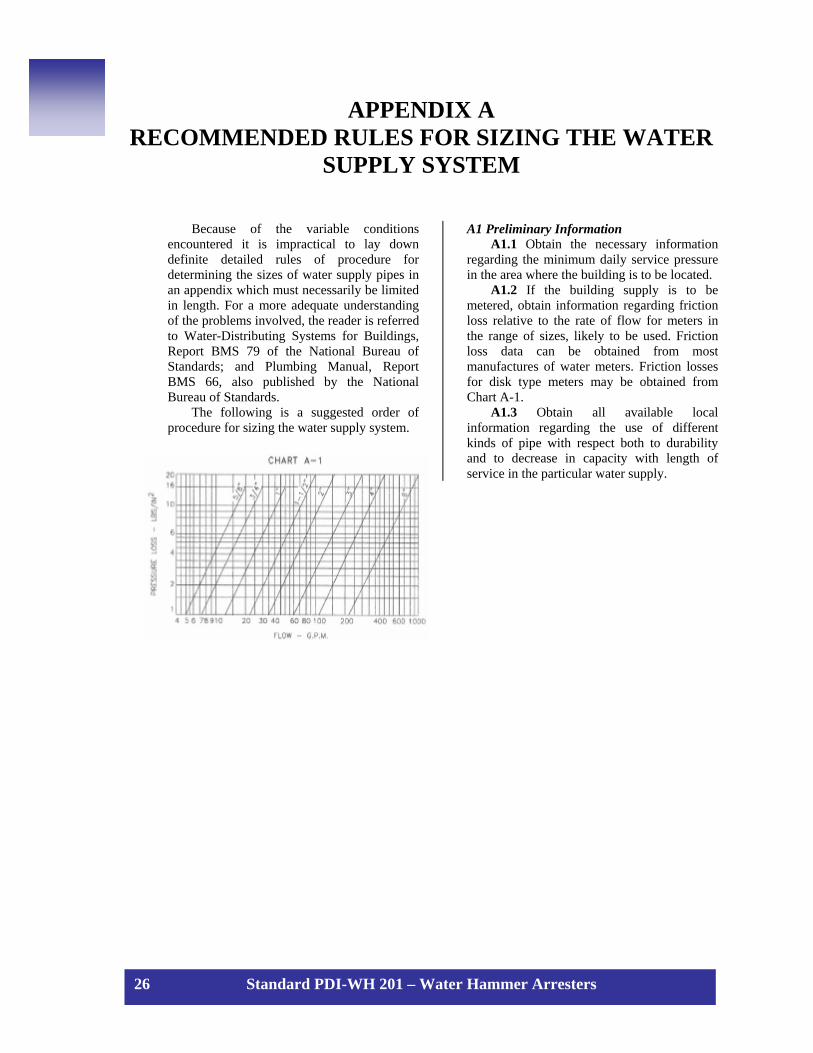
A1.2 If the building supply is to be metered, obtain information regarding friction loss relative to the rate of flow for meters in the range of sizes, likely to be used. Friction loss data can be obtained from most manufactures of water meters. Friction losses for disk type meters may be obtained from Chart A-1.
A1.3 Obtain all available local information regarding the use of different kinds of pipe with respect both to durability and to decrease in capacity with length of service in the particular water supply.
26 Standard PDI-WH 201 – Water Hammer Arresters

A2 Demand Load
A2.1 Estimate the supply demand for the building main and the principal branches and risers of the system by totaling the fixture units on each, Table A-2, and then by reading the corresponding ordinate from Chart A-2 or A-3, whichever is applicable.
A2.2 Estimate continuous -supply demands in gallons per minute for lawn sprinklers, air conditioners, etc., and add the sum to the total demand for fixtures. The result is the estimated supply demand for the building supply.
Fixture type2 private publicBathtub 2 4 1/2 1/2Bedpan 10 1Bidet 2 4 1/2 1/2Combination sink and tray 3 1/2 1/2Dental unit or cuspidor 1 3/8Dental lavatory 1 2 1/2 1/2Drinking fountain 1 2 3/8Kitchen sink 2 4 1/2 1/2Lavatory 1 2 3/8 3/8Laundry tray (1 or 2 compartments) 2 4 1/2 1/2Shower, each head4 2 4 1/2 1/2Sink; Service 2 4 1/2 1/2Urinal, pedestal 4 1Urinal (wall lip) 4 1/2Urinal stall 4 3/4Urinal with flush tank 2Urinal trough (for every 2 foot section) 2 1/2Wash sink, circulator or multiple (each set of faucets) 2 1/2 1/2Water Closet: F.V. 6 10 1Tank 3 5 3/8
TABLE A-2
Minimum cold water
Connections hot water
Weight in fixture - units3Demand weight of fixtures in fixture-units1
1 For supply outlets likely to impose continuous demands, estimate continuous supply separately and add to total demand for fixtures. 2 For fixtures not listed, weights may be assumed by comparing the fixture to a listed one using water in similar quantities and at similar
rates. 3 The given weights are for total demand for fixtures with both hot and cold water supplies. The weights for maximum separate demands
may be taken as seventy-five (75) percent of the listed demand for the supply. 4 Shower over bathtub does not add fixture unit to group.
27 Standard PDI-WH 201 – Water Hammer Arresters

A3 Permissible Friction Loss
A3.1 Decide what is the desirable minimum pressure that should be maintained at the highest fixture in the supply system. If the highest group of fixtures contains flush valves, the pressure for the group should not be less than fifteen (15) psi. For flush tank supplies, the available pressure may be not less than eight (8) psi.
A3.2 Determine the elevation of the highest fixture or group of fixtures above the water (street) main. Multiply this difference in elevation by forty-three hundredths (0.43). The result is the loss in static pressure in psi (pounds per square inch).
A3.3 Subtract the sum of loss in static pressure and the pressure to be maintained at the highest fixture from the average minimum daily service pressure. The result will be the pressure available for friction loss in the supply pipes, if no water meter is used. If a meter is to be installed, the friction loss in the meter for the estimated maximum demand should also be subtracted from the service pressure to determine the pressure loss available for friction loss in the supply pipes.
A3.4 Determine the developed length of pipe from the water (street) main to the highest fixture. If close estimates are desired, compute with the aid of Table A-3 the equivalent length of pipe for all fittings in the line from the water (street) main to the highest fixture and
add the sum to the developed length. The pressure available for friction loss in pounds per square inch, divided by the developed lengths of pipe from the water (street) main to the highest fixture, times one hundred (100), will be the average permissible friction loss per one hundred (100) foot length of pipe. A4 Size Of Building Supply
A4.1 Knowing the permissible friction loss per one hundred (100) feet of pipe and the total demand, the diameter of the building supply pipe may be obtained from Charts A-4, A-5, A-6 or A-7, whichever is applicable. The diameter of pipe on or next above the coordinate point corresponding to the estimated total demand and the permissible friction loss will be the size needed up to the first branch from the building supply pipe.
A4.2 If copper tubing or brass pipe is to be used for the supply piping, and if the character of the water is such that only slight changes in the hydraulic characteristics may be expected, Chart A-4 may be used.
A4.3 Chart A-5 should be used for ferrous pipe with only the most favorable water supply as regards corrosion and caking. If the water is hard or corrosive, Charts A-6 or A-7 will be applicable. For extremely hard water, it will be advisable to make additional allowances for the reduction of capacity of hot water lines in service.
Diameter of fitting (inches)
90 standard elbow
45 standard elbow
standard T 90
Coupling or straight run of T Gate valve
Globe valve
Angle Valve
Feet Feet Feet Feet Feet Feet Feet3/8 1 0.6 1.5 0.3 0.2 8 41/2 2 1.2 3 0.6 0.4 15 83/4 2.5 1.5 4 0.8 0.5 20 12
1 3 1.8 5 0.9 0.6 25 151-1/4 4 2.4 6 1.2 0.8 35 181-1/2 5 3 7 1.5 1 45 22
2 7 4 10 2 1.3 552-1/2 8 5 12 2.5 1.6 65 34
3 10 6 15 3 2 80 404 14 8 21 4 2.7 125 55 17 10 25 5 3.3 140 706 20 12 30 6 4 165 80
Equivalent length of pipe for various fittingsTABLE A-3
28
5
28 Standard PDI-WH 201 – Water Hammer Arresters

A5 Size of Principal Branches and Riser
A5.1 The required size of branches and risers may be obtained in the same manner as the building supply by obtaining the demand load on each branch or riser and using the permissible friction loss computed in Section A3.
A5.2 Fixture branches to the building supply, if they are sized for the same permissible friction loss per one hundred (100) feet of pipe as the branches and risers to the highest level in the building, may lead to inadequate water supply to the upper floor of the building. This may be controlled by: (1) Selecting the sizes of pipe for the different branches so that the total friction loss in each lower branch is approximately equal to the total loss in the riser, including both friction loss and loss in static pressure; (2) by throttling each such branch by means of a valve until the preceding balance is obtained; (3) by increasing the size of the building supply and risers above the minimum required to meet the maximum permissible friction loss. A6 General
A6.1 In general, a velocity greater than fifteen (15) feet per second in the main risers, or principal branches should not be employed, as objectionable line noise is likely to result.
A6.2 If a pressure reducing valve is used in the building supply, the developed length of supply piping and the permissible friction loss should be computed from the building side of the valve.
A6.3 The allowances in Table A-3 for fittings are based on non-recessed threaded fittings. For recessed threaded fittings and streamlined soldered
fittings, one-half (1/2) the allowances given in the table will be ample. A7 Example
A7.1 Assume an office building of four (4) stories and basement; pressure on the building side of the pressure-reducing valve of fifty-five (55) psi; an elevation of highest fixture above the pressure-reducing valve of forty-five (45) feet; a developed length of pipe from the pressure-reducing valve to the most distant fixture of two hundred (200) feet; and the fixtures to be installed with flush valves for water closets and stall urinals as follows:
Allowing for fifteen (15) psi at the highest fixture under maximum demand of three hundred and ten (310) gallons per minute (see Table A-4), the pressure applicable for friction loss is found by the following:
55 -{ 15+ (45x0.43)} = 20.65 psi The allowable friction loss per one hundred
(100) feet of pipe is therefore 100 x 20.65÷200= 10.32 psi If the pipe material and water supply are such
that Chart A-5 applies, the required diameter of the building supply is three (3) inches, and the required diameter of the branch to the hot-water heater is two (2) inches.
The sizes of the various branches and risers may be determined in the same manner as the size of the building supply or the branch to the hot water system - by estimating the demand for the riser or branch from Charts A-2 or A-3, and applying the total demand estimate for the branch, riser or section thereof, to the appropriate flow chart.
FixtureNo. of
fixturesFixture
unitsDemand (gallons
per minute)No. of
fixturesFixture
unitsDemand (gallons
per minute)Water Closets 130 1,300
Urinals 30 150Shower Heads 12 48 12
Lavatories 130 260 130Service Sinks 27 81 27Total 1,839 310 292 86
(27x3)x3/4=61
Building supply Branch to hot-water system
Table A-4Fixture Units and Estimated Demands
(12x4)x3/4=36(130x2)x3/4=195
29 Standard PDI-WH 201 – Water Hammer Arresters

SIZING WATER SYSTEMS
30 Standard PDI-WH 201 – Water Hammer Arresters

31 Standard PDI-WH 201 – Water Hammer Arresters

32 Standard PDI-WH 201 – Water Hammer Arresters

33 Standard PDI-WH 201 – Water Hammer Arresters

34 Standard PDI-WH 201 – Water Hammer Arresters

35 Standard PDI-WH 201 – Water Hammer Arresters
FIXTURE OR EQUIPMENT TOTAL C.W. H.W. FIXTURE OR EQUIPMENT TOTAL C.W. H.W.Baine Marie 2 - 2 Sink, Dish Soak (non-mobile) 3 2 1/2 2 1/2
1. KITCHEN AREAS
Carbonator 1 1/2 - Sink, Meat Preparation 3 2 1/2 2 1/2Coffee Urn Stand 2 2 - Sink, Pot and Pan, (per faucet) 4 3 3Cold Pan 1 1 - Sink, Salad Preparation 3 2 1/2 2 1/2Compressor, Refrigerator 1 1 - Sink, Silver Soak 3 2 1/2 2 1/2Grinder, Food Waste 3 3 - Sink, Vegetable 3 2 1/2 2 1/2Hose, Pre-Rinse 3 2 1/2 2 1/2 Soda Fountain Unit 1 1/2 -Hose Station 4 3 3 Steam Table 2 - 2Ice Maker 1 - - Tray Make-up Table 2 2 2Kettle Stand 2 2 2 Washer, Bottle with jet rinsers 2 2 -Milk Dispenser 1 - 1 Washer, Can 6 6 6Peeler, Vegetable 3 - 1 Washer, Glassware 4 1 1/2 3Sink, Back Bar 2 1 1/2 1 1/2 Washer, Nipple 2 1 1/2 1 1/2Sink, Baker’s Pan 3 2 1/2 2 1/2 Washer, Pot and Pan 6 - 6Sink, Cook’s 3 2 1/2 2 1/2 Washer, Silver 2 - 2Sink, Diet Kitchen 2 1 1/2 1 1/2 Water Station 1 1 -
Soup Kettle 2 1 1/2 1 1/2
FIXTURE OR EQUIPMENT TOTAL C.W. H.W. FIXTURE OR EQUIPMENT TOTAL C.W. H.W.Condenser, Drinking Fountain 1 1 - Hose, Bibb, Interior 4 4 -Condenser, Refrigeration 1 1 - Wall Hydrant 4 4 -Ice Cuber and Flakers 1 1 - Wall Hydrant, C.W. and H.W 4 3 3
FIXTURE OR EQUIPMENT TOTAL C.W. H.W. FIXTURE OR EQUIPMENT TOTAL C.W. H.W.Aspirator 2 2 - Sink, Animal Area 4 2 2Autopsy Table, Complete 4 3 2 Sing, Barium 3 2 1/2 2 1/2Autopsy Table, Aspirator 2 2 - Sink, Central Supply 3 2 1/2 2 1/2Autopsy Table, Flushing Hose 2 2 - Sink, Clean-up room 3 2 1/2 2 1/2Autopsy Table, Flushing Rim 3 3 - Sink, Clinical 10 10 3Autopsy Table, Sink Faucet 3 2 1/2 2 1/2 Sink, Clinical, Bed Pan Hose 10 10 4Autopsy Table, Waste Disposal 1 1/2 1 1/2 - Sink, Cup 1 1 -Bath, Arm 4 2 3 Sink, Floor 4 3 3Bath, Emergency 4 2 3 Sink, Formula Room 4 3 3Bath, Immersion 20 7 15 Sink, Laboratory 2 1 1/2 1 1/2Bath, Leg 10 4 7 Sink, Laboratory and Trough 3 2 1/2 1 1/2Bath, Sitz 4 2 3 Sink, Mop 3 3 3Bedpan Washer, Steam 10 10 - Sink, Pharmacy 2 1 1/2 1 1/2Bidet 4 3 3 Sink, Plaster 4 3 3Cleaner, Sonic 3 2 1/2 2 1/2 Sink, Nurse’s Station 2 1 1/2 1 1/2Cuspidor, Dental and Surgical 1 1 - Sink, Scrub-up 4 3 3Cuspidor, Dental Chair 1 1 - Sink, Clean Utility 3 2 1/2 2 1/2Drinking Fountain 1 1 - Sink, Soiled Utility 3 2 1/2 2 1/2Floor Drain, Flushing Type 10 10 - Sterilizer, Boiling Instrument 2 - 2Hose, Bed Pan General 2 1 1/2 1 1/2 Sterilizer, Boiling Utensil 2 - 2Hose, Bed Pan Private 1 1 1 Sterilizer, Pressure Instrument 2 2 -Lavatory, Barber 2 1 1/2 1 1/2 Sterilizer, Water 5 5 2Lavatory, Dental 1 1 1 Washer Sterilizer 6 6 -Lavatory, Nursery 2 1 1/2 1 1/2 Washer, Flask 4 - 4Lavatory, Scrub-up 2 1 1/2 1 1/2 Washer, Formula Bottle 4 4 -Lavatory, Treatment 1 1 1 Washer, Glove 4 3 3Microscope, Electron 1 1 - Washer, Needle 2 2 -Sanitizer, Boiling Instrument 2 - 2 Washer, Pipette 4 3 3Sanitizer, Boiling Utensil 2 - 2 Washer, Syringe 4 - 4Shower, Obstetrical 4 2 3 Washer, Tube 4 4 -
2. OTHER AREAS
3. HOSPITAL AND LABORATORY AREAS
Abstracted from “A Guide to Hospital Plumbing” by Lawrence Guss, Air Conditioning, Heating & Ventilating, October 1961.

DEFINITIONS 1. Air Chamber A closed section of pipe or
other container designed to trap air at atmospheric pressure mounted vertically in a tee in a water supply line intended to reduce water hammer pressures.
2. Air Chamber, Calculate An air chamber designed in accordance with the Dawson & Kalinske formula for reducing water hammer pressures.
3. Atmospheric Pressure Pressure, in lbs. per sq. in., atmospheric air above absolute zero pressure at ambient conditions (14.7 psi or 0.0 psig at standard conditions).
4. Branch Line A water supply line connecting one or more fixtures to a water supply main, riser or other branch.
5. Calculated Air Chamber See Air Chamber, Calculated.
6. Fixtures Sanitary plumbing fixture or related item of equipment which can demand water from a branch line.
7. Fixture Unit See definition on Page 19. 8. Flowing Pressure The gage pressure in a
flowing plumbing supply line immediately upstream of a fixture valve.
9. Gage Pressure Pressure, in lbs. per sq. in., above atmospheric indicated by a pressure gage.
10. Fps. Feet per second. 11. F.U. Fixture Unit. 12. G.P.M. U.S. Gallons per minute. 13. Kinetic Energy Energy available from a
flowing column of water due to its velocity. 14. P.D.I. The Plumbing and Drainage Institute. 15. Point of Relief Point of Relief is a larger mass
of water in the system, to which the branch is connected. Point of Relief could be a larger diameter main or riser, water tank, or hot water boiler. A larger diameter pipe is a main, which is at least two (2) nominal pipe sizes larger than the branch line in question. See also page 4, paragraph titled “Reaction.”
16. Pressure Transducer A pressure sensitive device that will produce an electric signal proportional to the pressure to which it is subjected, the signal being capable of amplification.
17. P.S.I. Pounds per Square Inch. 18. P.S.I.G. Pounds per Square Inch Gage;
pounds per square Inch above atmospheric pressure.
19. Reaction See Page 4. 20. Remote Fixture A single fixture located on a
branch line at a distance from the upstream end of the branch line.
21. Residual Pressure Same as flowing pressure. 22. Riser A water supply main in a building
conducting water vertically from one floor to another.
23. Shock The force generated in a piping system by water hammer.
24. Shock Absorber Water Hammer Arrester. 25. Shock Intensity See Page 4. 26. Static Pressure The pressure in lbs. per sq.
in., in a dormant or non-flowing branch line. 27. Surge The pressure increase, in lbs. per sq.
in., in a branch line caused by water hammer. 28. Surge Pressure The maximum pressure, in
lbs. per sq. in. gage, in a branch line caused by rapid valve closure.
29. Water Hammer See Page 4. 30. Water Hammer Arrester A device other
than an air chamber or calculated air chamber designed to provide continuous protection against excessive surge pressure.
31. Waterlogged Condition of an air chamber when all or part of its normal air content has been displaced by water.
32. Total Pressure The sum of the surge and flow pressures.
36 Standard PDI-WH 201 – Water Hammer Arresters


![Flame Arrester[1]](https://img.pdfslide.us/doc/110x75/547d2892b37959932b8b52bc/flame-arrester1.jpg)