Embed Size (px)
Citation preview
Water depth offers the opportunity
to enhance
BOP control systems.
Copyright: Shell Global Solutions BV
BOP control systems.
MCE Deepwater Development 2014
Jan van Wijk, Shell P&T
Mel Whitby, Cameron
DEFINITIONS & CAUTIONARY NOTE Reserves: Our use of the term “reserves” in this presentation means SEC proved oil and gas reserves.
Resources: Our use of the term “resources” in this presentation includes quantities of oil and gas not yet classified as SEC proved oil and gas reserves. Resources are consistent
with the Society of Petroleum Engineers 2P and 2C definitions.
Organic: Our use of the term Organic includes SEC proved oil and gas reserves excluding changes resulting from acquisitions, divestments and year-average pricing impact.
Resources plays: our use of the term ‘resources plays’ refers to tight, shale and coal bed methane oil and gas acreage.
The companies in which Royal Dutch Shell plc directly and indirectly owns investments are separate entities. In this presentation “Shell”, “Shell group” and “Royal Dutch Shell” are
sometimes used for convenience where references are made to Royal Dutch Shell plc and its subsidiaries in general. Likewise, the words “we”, “us” and “our” are also used to refer
to subsidiaries in general or to those who work for them. These expressions are also used where no useful purpose is served by identifying the particular company or companies.
‘‘Subsidiaries’’, “Shell subsidiaries” and “Shell companies” as used in this presentation refer to companies in which Royal Dutch Shell either directly or indirectly has control, by having
either a majority of the voting rights or the right to exercise a controlling influence. The companies in which Shell has significant influence but not control are referred to as
“associated companies” or “associates” and companies in which Shell has joint control are referred to as “jointly controlled entities”. In this presentation, associates and jointly
controlled entities are also referred to as “equity-accounted investments”. The term “Shell interest” is used for convenience to indicate the direct and/or indirect (for example, through
our 23% shareholding in Woodside Petroleum Ltd.) ownership interest held by Shell in a venture, partnership or company, after exclusion of all third-party interest.
This presentation contains forward-looking statements concerning the financial condition, results of operations and businesses of Royal Dutch Shell. All statements other than
statements of historical fact are, or may be deemed to be, forward-looking statements. Forward-looking statements are statements of future expectations that are based on
Copyright: Shell Global Solutions BV
statements of historical fact are, or may be deemed to be, forward-looking statements. Forward-looking statements are statements of future expectations that are based on
management’s current expectations and assumptions and involve known and unknown risks and uncertainties that could cause actual results, performance or events to differ
materially from those expressed or implied in these statements. Forward-looking statements include, among other things, statements concerning the potential exposure of Royal
Dutch Shell to market risks and statements expressing management’s expectations, beliefs, estimates, forecasts, projections and assumptions. These forward-looking statements
are identified by their use of terms and phrases such as ‘‘anticipate’’, ‘‘believe’’, ‘‘could’’, ‘‘estimate’’, ‘‘expect’’, ‘‘intend’’, ‘‘may’’, ‘‘plan’’, ‘‘objectives’’, ‘‘outlook’’, ‘‘probably’’, ‘‘project’’,
‘‘will’’, ‘‘seek’’, ‘‘target’’, ‘‘risks’’, ‘‘goals’’, ‘‘should’’ and similar terms and phrases. There are a number of factors that could affect the future operations of Royal Dutch Shell and could
cause those results to differ materially from those expressed in the forward-looking statements included in this presentation, including (without limitation): (a) price fluctuations in
crude oil and natural gas; (b) changes in demand for Shell’s products; (c) currency fluctuations; (d) drilling and production results; (e) reserves estimates; (f) loss of market share and
industry competition; (g) environmental and physical risks; (h) risks associated with the identification of suitable potential acquisition properties and targets, and successful
negotiation and completion of such transactions; (i) the risk of doing business in developing countries and countries subject to international sanctions; (j) legislative, fiscal and
regulatory developments including potential litigation and regulatory measures as a result of climate changes; (k) economic and financial market conditions in various countries and
regions; (l) political risks, including the risks of expropriation and renegotiation of the terms of contracts with governmental entities, delays or advancements in the approval of
projects and delays in the reimbursement for shared costs; and (m) changes in trading conditions. All forward-looking statements contained in this presentation are expressly
qualified in their entirety by the cautionary statements contained or referred to in this section. Readers should not place undue reliance on forward-looking statements. Additional
factors that may affect future results are contained in Royal Dutch Shell’s 20-F for the year ended 31 December, 2013 (available at www.shell.com/investor and www.sec.gov ).
These factors also should be considered by the reader. Each forward-looking statement speaks only as of the date of this presentation, 08-10 April, 2014. Neither Royal Dutch Shell
nor any of its subsidiaries undertake any obligation to publicly update or revise any forward-looking statement as a result of new information, future events or other information. In
light of these risks, results could differ materially from those stated, implied or inferred from the forward-looking statements contained in this presentation. There can be no assurance
that dividend payments will match or exceed those set out in this presentation in the future, or that they will be made at all.
We use certain terms in this presentation, such as discovery potential, that the United States Securities and Exchange Commission (SEC) guidelines strictly prohibit us from including
in filings with the SEC. U.S. Investors are urged to consider closely the disclosure in our Form 20-F, File No 1-32575, available on the SEC website www.sec.gov. You can also
obtain this form from the SEC by calling 1-800-SEC-0330.
Content
• The drivers for development of the SPRA.
• How does it work (the fundamentals)
• SPRA control system.
• SPRA performance.
Copyright: Shell Global Solutions BV
• SPRA performance.
• Evaluation of other solutions.
• Prototype testing and FMCEA.
• Conclusions.
• Q&A
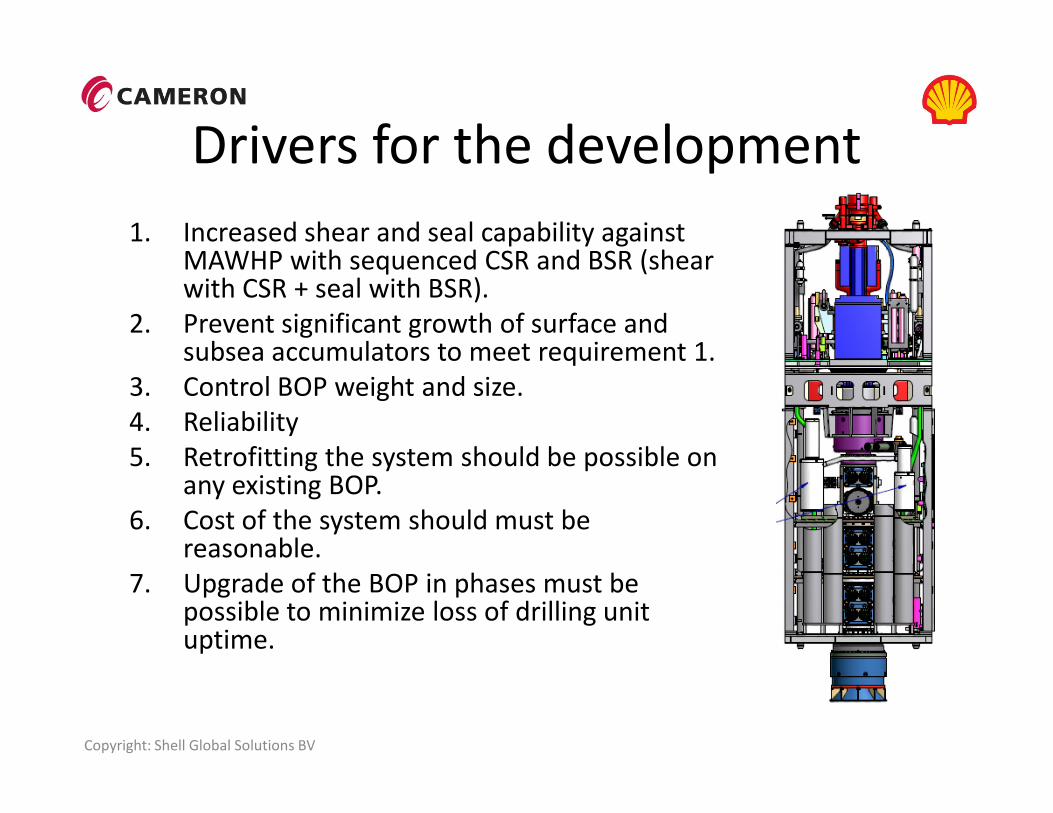
Drivers for the development
1. Increased shear and seal capability against MAWHP with sequenced CSR and BSR (shear with CSR + seal with BSR).
2. Prevent significant growth of surface and subsea accumulators to meet requirement 1.
3. Control BOP weight and size.
4. Reliability
Copyright: Shell Global Solutions BV
4. Reliability
5. Retrofitting the system should be possible on any existing BOP.
6. Cost of the system should must be reasonable.
7. Upgrade of the BOP in phases must be possible to minimize loss of drilling unit uptime.
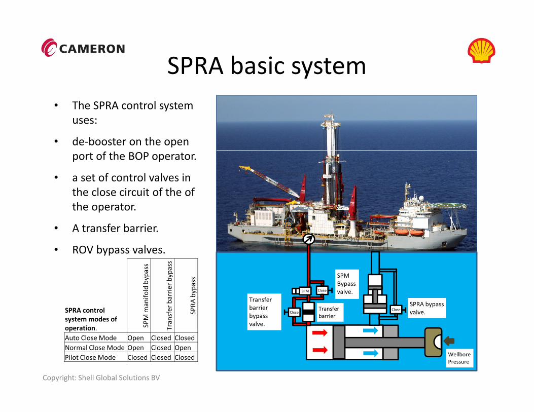
SPRA basic system
• The SPRA control system
uses:
• de-booster on the open
port of the BOP operator.
• a set of control valves in
the close circuit of the of
the operator.
Copyright: Shell Global Solutions BV
Wellbore
Pressure
Transfer
barrier
Close
SPM
Close
Close
SPM
Bypass
valve.
Transfer
barrier
bypass
valve.
SPRA bypass
valve.
the operator.
• A transfer barrier.
• ROV bypass valves.
SPRA control
system modes of
operation. SP
M m
an
ifo
ld b
yp
ass
Tra
nsf
er
ba
rrie
r b
yp
ass
SP
RA
by
pa
ss
Auto Close Mode Open Closed Closed
Normal Close Mode Open Closed Open
Pilot Close Mode Closed Closed Closed
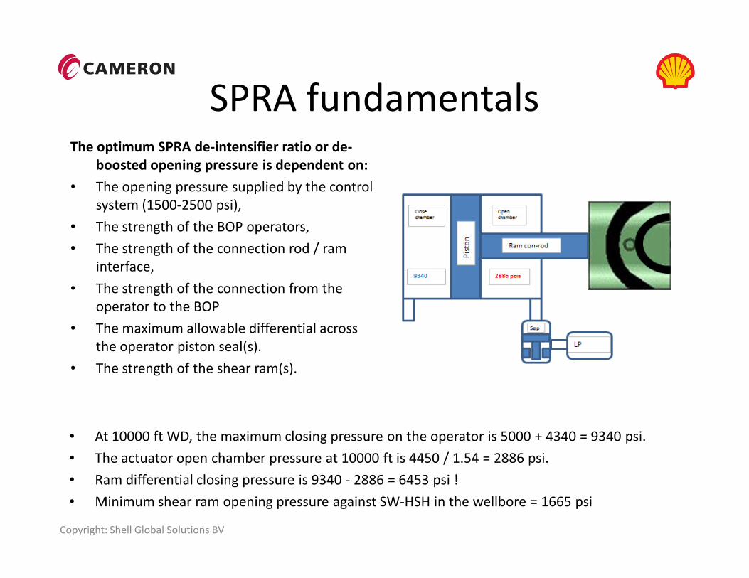
SPRA fundamentalsThe optimum SPRA de-intensifier ratio or de-
boosted opening pressure is dependent on:
• The opening pressure supplied by the control
system (1500-2500 psi),
• The strength of the BOP operators,
• The strength of the connection rod / ram
interface,
• The strength of the connection from the
Copyright: Shell Global Solutions BV
• At 10000 ft WD, the maximum closing pressure on the operator is 5000 + 4340 = 9340 psi.
• The actuator open chamber pressure at 10000 ft is 4450 / 1.54 = 2886 psi.
• Ram differential closing pressure is 9340 - 2886 = 6453 psi !
• Minimum shear ram opening pressure against SW-HSH in the wellbore = 1665 psi
• The strength of the connection from the
operator to the BOP
• The maximum allowable differential across
the operator piston seal(s).
• The strength of the shear ram(s).

SPRA Control system
Copyright: Shell Global Solutions BV
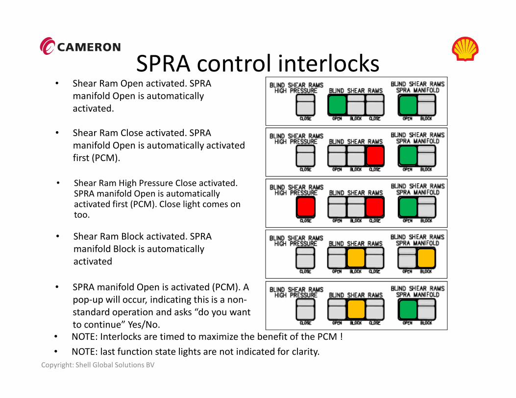
SPRA control interlocks
• Shear Ram Close activated. SPRA
manifold Open is automatically activated
first (PCM).
• Shear Ram High Pressure Close activated. SPRA manifold Open is automatically activated first (PCM). Close light comes on
• Shear Ram Open activated. SPRA
manifold Open is automatically
activated.
Copyright: Shell Global Solutions BV
• Shear Ram Block activated. SPRA
manifold Block is automatically
activated
activated first (PCM). Close light comes on too.
• SPRA manifold Open is activated (PCM). A
pop-up will occur, indicating this is a non-
standard operation and asks “do you want
to continue” Yes/No.
• NOTE: Interlocks are timed to maximize the benefit of the PCM !
• NOTE: last function state lights are not indicated for clarity.
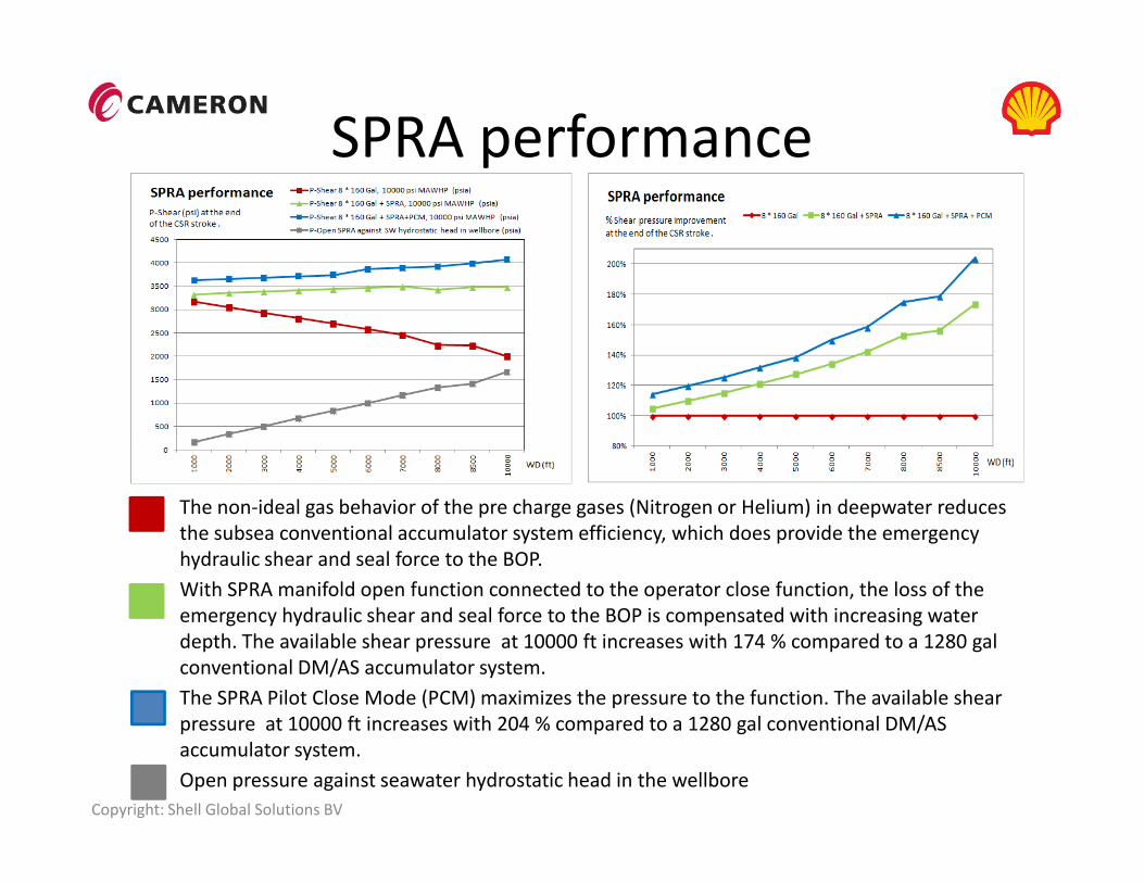
SPRA performance
Copyright: Shell Global Solutions BV
• The non-ideal gas behavior of the pre charge gases (Nitrogen or Helium) in deepwater reduces
the subsea conventional accumulator system efficiency, which does provide the emergency
hydraulic shear and seal force to the BOP.
• With SPRA manifold open function connected to the operator close function, the loss of the
emergency hydraulic shear and seal force to the BOP is compensated with increasing water
depth. The available shear pressure at 10000 ft increases with 174 % compared to a 1280 gal
conventional DM/AS accumulator system.
• The SPRA Pilot Close Mode (PCM) maximizes the pressure to the function. The available shear
pressure at 10000 ft increases with 204 % compared to a 1280 gal conventional DM/AS
accumulator system.
• Open pressure against seawater hydrostatic head in the wellbore
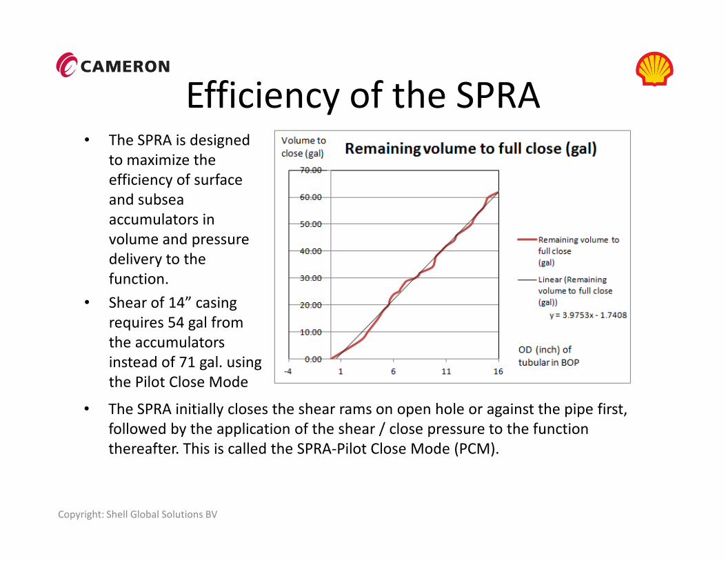
Efficiency of the SPRA• The SPRA is designed
to maximize the
efficiency of surface
and subsea
accumulators in
volume and pressure
delivery to the
function.
Copyright: Shell Global Solutions BV
• The SPRA initially closes the shear rams on open hole or against the pipe first,
followed by the application of the shear / close pressure to the function
thereafter. This is called the SPRA-Pilot Close Mode (PCM).
function.
• Shear of 14” casing
requires 54 gal from
the accumulators
instead of 71 gal. using
the Pilot Close Mode
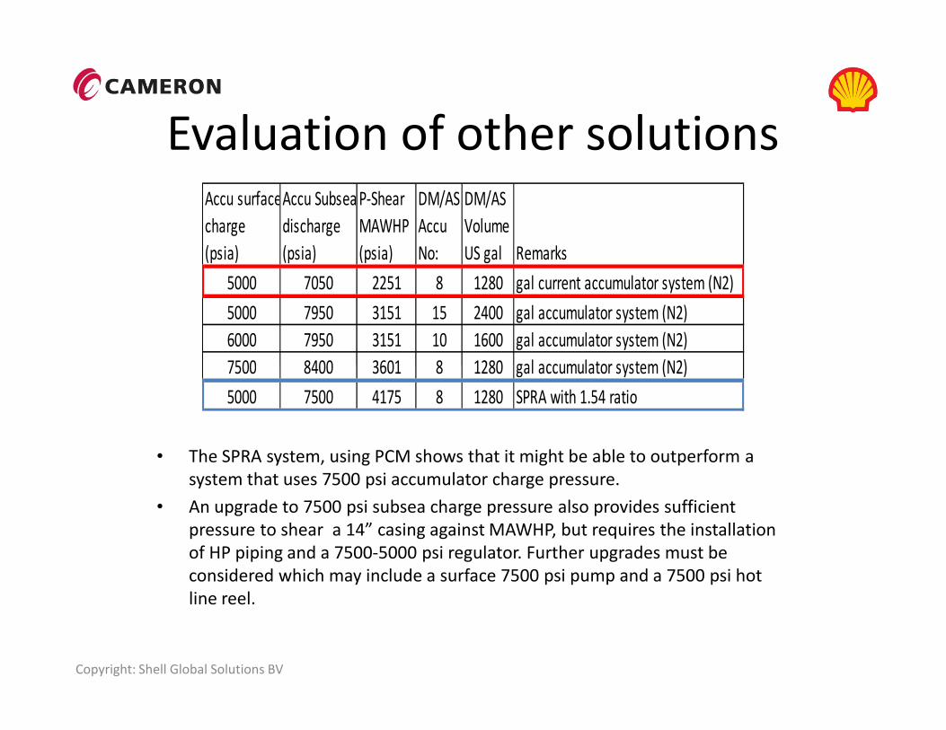
Evaluation of other solutionsAccu surfaceAccu Subsea P-Shear DM/AS DM/AS
charge discharge MAWHP Accu Volume
(psia) (psia) (psia) No: US gal Remarks
5000 7050 2251 8 1280 gal current accumulator system (N2)
5000 7950 3151 15 2400 gal accumulator system (N2)
6000 7950 3151 10 1600 gal accumulator system (N2)
7500 8400 3601 8 1280 gal accumulator system (N2)
Copyright: Shell Global Solutions BV
• The SPRA system, using PCM shows that it might be able to outperform a
system that uses 7500 psi accumulator charge pressure.
• An upgrade to 7500 psi subsea charge pressure also provides sufficient
pressure to shear a 14” casing against MAWHP, but requires the installation
of HP piping and a 7500-5000 psi regulator. Further upgrades must be
considered which may include a surface 7500 psi pump and a 7500 psi hot
line reel.
7500 8400 3601 8 1280 gal accumulator system (N2)
5000 7500 4175 8 1280 SPRA with 1.54 ratio

Prototype testing and FMCEA
• The SPRA system was tested to an equivalent WD of 15000 ft and both de-booster and control system worked as designed.
• Components have in detail been reviewed for their suitability and reliability.
SPRA
System
SPRA prepared for Hyperbaric
Chamber testing
Copyright: Shell Global Solutions BV
reliability.
• Control system hardware and software must go through an FMECA process as part of QA & QC before installation.
• BOP control software updates must be extensively tested on a simulator control system before installed on the control system.
System
EVO ram
bonnet
Hyperbaric
chamber test
frame
Position for the
SPRA control
system
components
Conclusions
• Weight of the SPRA system for both CSR + BSR is +/- 45000 lbs and required upgrade of the BOP crane.
• The SPRA aims to deliver the shear and seal force needed to support the sequencing of CSR and BSR.
• Design verification showed that the connection rods from the operators must be upgraded to a higher YS NACE compliant CRA material in order to use the de-booster ratio of 1.54. Solutions have been identified.
Copyright: Shell Global Solutions BV
been identified.
• Installation on existing BOPs is possible.
• Alternative solution for the subsea accumulators will be charging to 7500 psi. Consideration must then be given for installation of a 7500 psi hot line, 7.5K to 5K regulator and 7500 psi pump. Surface accumulator count may also have to be adjusted to provide the shear and seal pressure under normal operations.
Q&A
Raising the
Performance
together
Copyright: Shell Global Solutions BV
together