Embed Size (px)
Citation preview
Water Bottle Flipping Physics
P.J. Dekker1, L.A.G. Eek1, M.M. Flapper1, H.J.C. Horstink1, A.R.
Meulenkamp1, J. van der Meulen1, E.S. Kooij1,2, J.H. Snoeijer1,3, A. Marin1,3
1 Faculty of Science and Technology, University of Twente,P.O. Box 217, 7500 AE Enschede, The Netherlands
2 Physics of Interfaces and Nanomaterials, MESA+ Institute for Nanotechnology,University of Twente, P. O. Box 217, 7500 AE Enschede, The Netherlands
3 Physics of Fluids Group, J.M. Burgers Center for Fluid Dynamics,University of Twente, P.O. Box 217, 7500 AE Enschede, The Netherlands
(Dated: December 25, 2017)
The water bottle flipping challenge consists of spinning a bottle, partially filled with water, andmaking it land upright. It is quite a striking phenomenon, since at first sight it appears ratherimprobable that a tall rotating bottle could make such a stable landing. Here we analyze thephysics behind the water bottle flip, based on experiments and an analytical model that can beused in the classroom. Our measurements show that the angular velocity of the bottle decreasesdramatically, enabling a nearly vertical descent and a successful landing. The reduced rotationis due to an increase of the moment of inertia, caused by the in-flight redistribution of the watermass along the bottle. Experimental and analytical results are compared quantitatively, and wedemonstrate how to optimize the chances for a successful landing.
I. INTRODUCTION
In May 2016, a senior high school student calledMichael Senatore enters a stage carrying a partially filledbottle of water. He is participating in the school’s annualtalent show and the auditorium is packed. There is musicplaying in the background as he approaches the center ofthe stage in a funny way (swagger move). Suddenly hegets serious, stands straight, focuses on a table standingin front of him and throws the bottle in the air with aspin. The bottle flipped once and landed standing per-fectly upright on a table. This brings down the houseand the students bursts in wild cheers. Everything wasfilmed with a smartphone camera1. Within weeks, this30 seconds clip becomes viral on the internet and kidsaround the globe are seen attempting the “water bottleflipping challenge”, as is it known nowadays2,3. MichaelSenatore ended up selling the famous bottle for 15.000$(or at least one signed by him)4.
Rotational physics often involves rather counterintu-itive phenomena like the rotation of cats in free-fall12 orOlympic divers13, but the remarkable water bottle flipis no exception. Yet, the flip offers an original and veryinsightful illustration of the fundamental principles of ro-tational mechanics. In Fig. 1(a) (and in the supplemen-tary video footage14) we present a series of snapshotsof a successful flip. At first sight it appears rather im-probable that a tall rotating bottle could land stably inupright position. After all, once released, the bottle’s an-gular momentum must be conserved. For a rigid body,the conservation of angular momentum implies a rota-tion with a constant angular velocity making a smoothlanding rather unlikely. However, the sloshing of the wa-ter leads to a redistribution of the mass along the bottle.This change of mass distribution is clearly visible in thetop row of Fig. 1 (while the bottle is in the air), and willincrease the moment of inertia. Conservation of angu-
lar momentum then implies a decrease of the rotationalvelocity – leaving the impression of the bottle being sus-pended horizontally in the air for a moment. When per-formed successfully, the flip ends with a nearly verticaldescent that is followed by a smooth landing.
In this paper we demonstrate how the water bottle flipcan be used in the classroom. In Sec. II we show howthe complex dynamics of the bottle can be imaged inexperiments, and how it can be analyzed by separatingthe motion in the translation of the center of mass and arotation around the center of mass. Since the physics ofwater sloshing is highly complex in itself, we present analternative that is more suitable for analysis: The “tennisbottle flip”, shown in Fig. 1(b) (and in the supplementaryvideo footage14). In this system the water is replaced bytwo tennis balls – indeed, the successful tennis bottleflip clearly demonstrates that the redistribution of massis the physical ingredient behind the flip. Subsequently,in Sec. III we show how the flip can be described by atheoretical model, even allowing quantitative comparisonto experiments.
Based on the observations and modeling, we close byaddressing an important question that arises when at-tempting a water bottle flip challenge (Sec. IV): Why isthere an optimal amount of water in the bottle? Millionsof flippers seem to disagree on the precise value, but theydo agree that the optimal filling fraction should be be-tween 1/4 and 1/3 of the total height of the bottle. Canwe explain these values from mechanical principles?
II. EXPERIMENTS
We start by describing how to visualize the dynamicsduring a bottle flip, and how to analyze the resultingmotion. The experiment is designed along the classicalapproach for the dynamics of extended bodies6,7: The
arX
iv:1
712.
0827
1v1
[ph
ysic
s.fl
u-dy
n] 2
2 D
ec 2
017

2
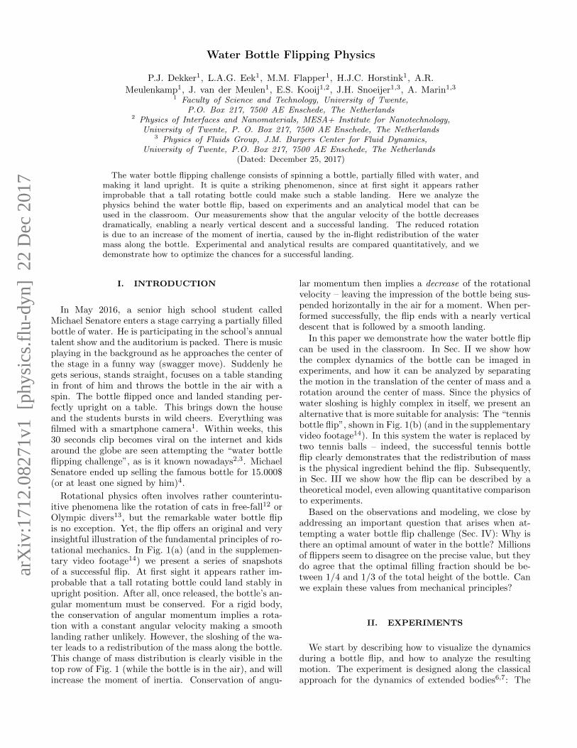
FIG. 1. Compositional photographs of a water bottle flip (top), and a tennis bottle flip (bottom). In both cases the redistributionof mass inside the bottle leads to an increase of the moment of inertia – slowing down its rotational speed and allowing for anear-vertical descent.
FIG. 2. Sketch of the geometrical parameters for the waterbottle and tennis bottle. The total height of the bottle is H,while the distribution of water/balls is indicated as h. Theaxis of rotation is indicated as well.
motion is decomposed into a translation of the center ofmass and a rotation around the center of mass. Thisdecomposition is natural since the only external force isgravity, which exerts no torque around the center of mass.As such, the water bottle flip serves as a prime exampleof conservation of angular momentum.
Apart from the water bottle and the tennis bottleshown in Fig. 1, we will also consider a “rigid bottle” thatcontains an immobilized mass. The rigid bottle serves
two purposes: to verify if we recover the usual rigid bodyrotation, and to highlight the importance of the movablemass for a successful bottle flip.
A. Experimental setup and analysis
The experimental setup used in this study consists ofa black background, a lamp for illumination, and a dig-ital camera α-6000. Each experimental run (or bottleflip) takes roughly 1 second. Here we recorded the filmsat 50 frames per second, 1/1600 s of shutter time and2 megapixels resolution. Our recommendation is to usea minimum of 20 frames per second to gather enoughdata points, a maximum shutter time of 1/200 s to avoidblur in the moving bottle and a minimum resolution of1 megapixels (most smartphone-cameras satisfy such re-quirements nowadays). We typically ran 10 successfulflips per bottle type with the same fillings, and select thecleanest landings among them for analysis.
The rotational motion is quantified by the angular ve-locity ω = dθ/dt. This quantity can be measured bytracing the top and bottom of the bottle on the videos.Another key ingredient of the analysis is to determinethe motion of the center of mass of the total system. Forthe rigid bottle, the center of mass obviously remains ata fixed position along the bottle for all times. However,it is rather difficult to accurately determine the center ofmass of the sloshing water – from the images one cannotinfer the precise distribution of water inside the bottle.Here we simply proceed by an approximate analysis thatis detailed in Sec. III B, based on the maximum height of
3
0 0.5 1 1.5 2
X/H
0
0.5
1
1.5
2
Y/H
Rigid Bottle
0 0.5 1
X/H
0
0.5
1
1.5
2
Y/H
Water Bottle
0 0.5 1 1.5
X/H
0
0.5
1
1.5
2
2.5
Y/H
Tennis Bottle
a b c
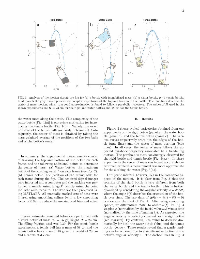
FIG. 3. Analysis of the motion during the flip for (a) a bottle with immobilized mass, (b) a water bottle, (c) a tennis bottle.In all panels the gray lines represent the complex trajectories of the top and bottom of the bottle. The blue lines describe thecenter of mass motion, which to a good approximation is found to follow a parabolic trajectory. The values of H used in theshown experiments are H = 23 cm for the rigid and water bottles and 28 cm for the tennis bottle.
the water mass along the bottle. This complexity of thewater bottle [Fig. 1(a)] is our prime motivation for intro-ducing the tennis bottle [Fig. 1(b)]. Namely, the exactpositions of the tennis balls are easily determined. Sub-sequently, the center of mass is obtained by taking themass-weighted average of the positions of the two ballsand of the bottle’s center.
In summary, the experimental measurements consistof tracking the top and bottom of the bottle on eachframe, and the following additional points to determinethe center of mass: (a) Water bottle: the maximumheight of the sloshing water h on each frame (see Fig. 2).(b) Tennis bottle: the position of the tennis balls foreach frame during the flip. The acquired digital imageswere imported into a computer and the tracking was per-formed manually using ImageJ8, simply using the pointtool with auto-measure. The data was then processed us-ing MATLAB9. All manually tracked sets of data werefiltered using smoothing splines (with a low smoothingfactor of 0.99) to reduce the user-induced bias and noise.
The experiments presented below were performed witha water bottle of mass mb = 25 gr, height H = 23 cm.The filling fraction used was 0.39. For the tennis bottleexperiments, a tennis ball has a mass of 58 gr, and thetennis bottle has a mass of 48 gr and a height of 28 cmand a radius of 3.7 cm.
B. Results
Figure 3 shows typical trajectories obtained from ourexperiments on the rigid bottle (panel a), the water bot-tle (panel b), and the tennis bottle (panel c). The vari-ous curves respectively trace out the edges of the bot-tle (gray lines) and the center of mass position (bluelines). In all cases, the center of mass follows the ex-pected parabolic trajectory associated to a free-fallingmotion. The parabola is most convincingly observed forthe rigid bottle and tennis bottle [Fig. 3(a,c)]. In theseexperiments the center of mass was indeed accurately de-termined, while this measurement was more approximatefor the sloshing the water [Fig. 3(b)].
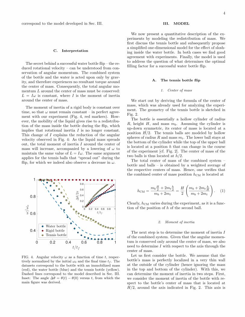
Our prime interest, however, lies in the rotational as-pects of the motion. It is clear from Fig. 3 that therotation of the rigid bottle is very different from boththe water bottle and the tennis bottle. This is furtherquantified by considering the angular velocity ω = dθ/dt,where the angle θ(t) describes the orientation of the bot-tle over time. The raw data of ∆θ(t) = θ(t) − θ(t = 0)is shown in the inset of Fig. 4. After using smoothingsplines, we differentiate ∆θ(t) to obtain ω(t). In Fig. 4we plot ω (normalized by the initial value ω0) versus time(normalized by the time of landing tf ). As expected, theangular velocity is perfectly constant for the rigid bottle(red markers). By contrast, ω is found to decrease dra-matically for both the water bottle (blue) and the tennisbottle (yellow). These results reveal that a gentle land-ing can be achieved due to a significant reduction of thebottle’s angular velocity ω. The dashed lines in Fig. 4
4
correspond to the model developed in Sec. III.
C. Interpretation
The secret behind a successful water bottle flip – the re-duced rotational velocity – can be understood from con-servation of angular momentum. The combined systemof the bottle and the water is acted upon only by grav-ity, and therefore experiences no resultant torque aroundthe center of mass. Consequently, the total angular mo-mentum L around the center of mass must be conserved:L = Iω is constant, where I is the moment of inertiaaround the center of mass.
The moment of inertia of a rigid body is constant overtime, so that ω must remain constant – in perfect agree-ment with our experiment (Fig. 4, red markers). How-ever, the mobility of the liquid gives rise to a redistribu-tion of the mass inside the bottle during the flip, whichimplies that rotational inertia I is no longer constant.This change of I explains the reduction of the angularvelocity observed in Fig. 4: As the liquid mass spreadsout, the total moment of inertia I around the center ofmass will increase, accompanied by a lowering of ω tomaintain the same value of L = Iω. The same argumentapplies for the tennis balls that “spread out” during theflip, for which we indeed also observe a decrease in ω.
0 0.2 0.4 0.6 0.8 1
t/tf
0.4
0.6
0.8
1
ω/ω
o
Water bottle
Rigid bottle
Tennis bottle
0 0.2 0.4 0.6 0.8 1
t/tf
0
0.2
0.4
0.6
0.8
∆θ/2π
FIG. 4. Angular velocity ω as a function of time t, respec-tively normalized by the initial ω0 and the final time tf . Thedatasets correspond to the bottle with an immobilized mass(red), the water bottle (blue) and the tennis bottle (yellow).Dashed lines correspond to the model described in Sec. III.Inset: The angle ∆θ = θ(t) − θ(0) versus t, from which themain figure was derived.
III. MODEL
We now present a quantitative description of the ex-periments by modeling the redistribution of mass. Wefirst discuss the tennis bottle and subsequently proposea simplified one-dimensional model for the effect of slosh-ing inside the water bottle. In both cases we find goodagreement with experiments. Finally, the model is usedto address the question of what determines the optimalfilling factor for a successful water bottle flip.
A. The tennis bottle flip
1. Center of mass
We start out by deriving the formula of the center ofmass, which was already used for analyzing the experi-ment. The geometry of the tennis bottle is sketched inFig. 2.
The bottle is essentially a hollow cylinder of radiusR, height H, and mass mb. Assuming the cylinder isup-down symmetric, its center of mass is located at aposition H/2. The tennis balls are modeled by hollowspheres of radius R and mass mt. The lower ball stays atthe bottom of the cylinder while the top of the upper ballis located at a position h that can change in the courseof the experiment [cf. Fig. 2]. The center of mass of thetwo balls is thus located at h/2.
The total center of mass of the combined system –bottle and balls – is obtained by a weighted average ofthe respective centers of mass. Hence, one verifies thatthe combined center of mass position hCM is located at
hCM =mb
H2 + 2mt
h2
mb + 2mt=H
2
(mb + 2mt
hH
mb + 2mt
). (1)
Clearly, hCM varies during the experiment, as it is a func-tion of the position of h of the second ball.
2. Moment of inertia
The next step is to determine the moment of inertia Iof the combined system. Given that the angular momen-tum is conserved only around the center of mass, we alsoneed to determine I with respect to the axis through thecenter of mass.
Let us first consider the bottle. We assume that thebottle’s mass is perfectly localized in a very thin wallat the outside of the cylinder (hence ignoring the massin the top and bottom of the cylinder). With this, wecan determine the moment of inertia in two steps. First,we consider the moment of inertia of the bottle with re-spect to the bottle’s center of mass that is located atH/2, around the axis indicated in Fig. 2. This axis is
5
perpendicular to the cylinder’s symmetry axis and thecorresponding moment of inertia reads
I ′b =mb
12
(6R2 +H2
). (2)
However, the rotation takes place around the center ofmass of the total system hCM, defined by (1). Hence, theaxis of rotation in the experiment is parallel to the axisused for (2), but shifted by a distance H
2 − hCM. Therelevant moment of inertia is then obtained by using theparallel axis theorem. This gives
Ib = I ′b +mb
(H
2− hCM
)2
=mb
12
(6R2 +H2
)+mb
(H
2− hCM
)2
. (3)
In a similar fashion, one obtains the moment of inertiaof the two tennis balls. Approximating the balls as thin-walled hollow spheres, we obtain
I1 =2
3mtR
2 +mt (R− hCM)2, (4)
I2 =2
3mtR
2 +mt (h−R− hCM)2. (5)
The first terms on the right hand side are the sphere’s mo-ment of inertia around its center of mass, while the sec-ond terms account for the parallel displacement to hCM
of the total system.Finally, the total moment of inertia during the tennis
bottle flip reads
I(h) = Ib + I1 + I2. (6)
Each of these terms is a function of h, due to the depen-dence of hCM on the position h of the second ball.
3. Comparison to experiments
To compare the model to experiments, we make useof the fact that the angular momentum around the cen-ter of mass, L = Iω, must be conserved during the flip.According to this, we directly conclude that the dimen-sionless angular frequency ω(t)/ω0 can be expressed as
ω(t)
ω0=
I0I(h)
, (7)
with I(h) given by (6). Here we introduced the initialmoment of inertia I0 = I(h0), which corresponds to thesituation prior to the flip when the two tennis balls are atthe bottom of the container. Upon inspection of Fig. 2(a)one finds h0 = 4R.
We now present two tests of our predictions. First, weinsert the experimentally obtained h(t) in (6) and use (7)to predict the angular velocity ω(t). The result is shownas the yellow dashed line in Fig. 4. Clearly, it gives avery good description of the experimental data.
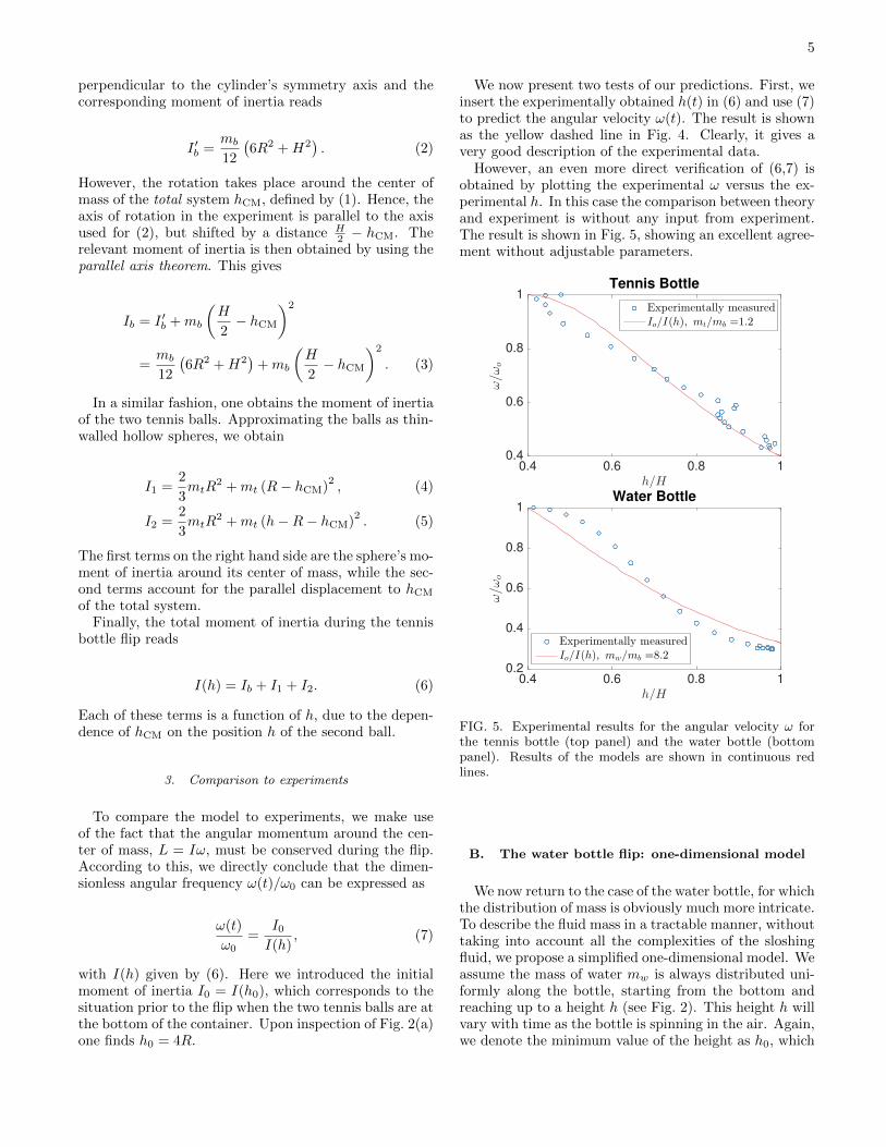
However, an even more direct verification of (6,7) isobtained by plotting the experimental ω versus the ex-perimental h. In this case the comparison between theoryand experiment is without any input from experiment.The result is shown in Fig. 5, showing an excellent agree-ment without adjustable parameters.
0.4 0.6 0.8 1
h/H
0.4
0.6
0.8
1
ω/ωo
Tennis Bottle
Experimentally measuredIo/I(h), mt/mb =1.2
0.4 0.6 0.8 1
h/H
0.2
0.4
0.6
0.8
1
ω/ω
oWater Bottle
Experimentally measuredIo/I(h), mw/mb =8.2
FIG. 5. Experimental results for the angular velocity ω forthe tennis bottle (top panel) and the water bottle (bottompanel). Results of the models are shown in continuous redlines.
B. The water bottle flip: one-dimensional model
We now return to the case of the water bottle, for whichthe distribution of mass is obviously much more intricate.To describe the fluid mass in a tractable manner, withouttaking into account all the complexities of the sloshingfluid, we propose a simplified one-dimensional model. Weassume the mass of water mw is always distributed uni-formly along the bottle, starting from the bottom andreaching up to a height h (see Fig. 2). This height h willvary with time as the bottle is spinning in the air. Again,we denote the minimum value of the height as h0, which
6
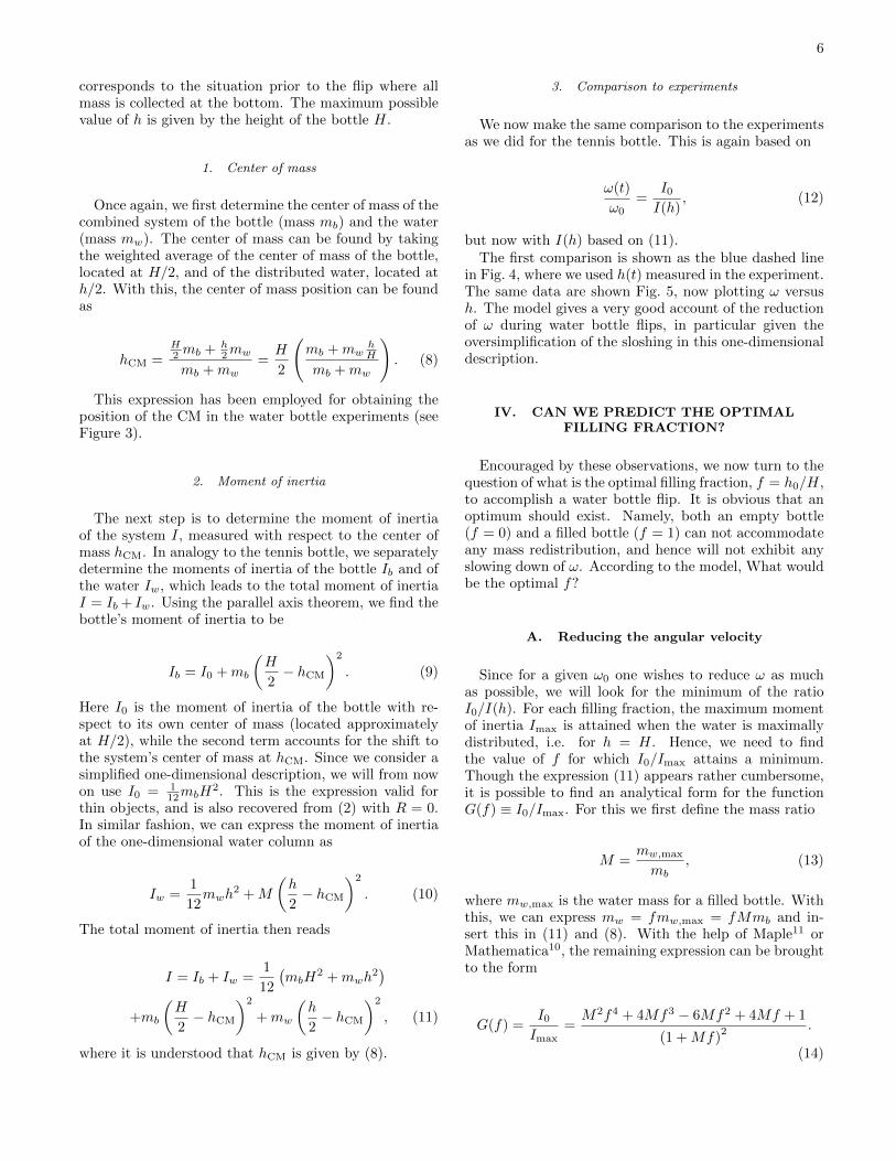
corresponds to the situation prior to the flip where allmass is collected at the bottom. The maximum possiblevalue of h is given by the height of the bottle H.
1. Center of mass
Once again, we first determine the center of mass of thecombined system of the bottle (mass mb) and the water(mass mw). The center of mass can be found by takingthe weighted average of the center of mass of the bottle,located at H/2, and of the distributed water, located ath/2. With this, the center of mass position can be foundas
hCM =H2 mb + h
2mw
mb +mw=H
2
(mb +mw
hH
mb +mw
). (8)
This expression has been employed for obtaining theposition of the CM in the water bottle experiments (seeFigure 3).
2. Moment of inertia
The next step is to determine the moment of inertiaof the system I, measured with respect to the center ofmass hCM. In analogy to the tennis bottle, we separatelydetermine the moments of inertia of the bottle Ib and ofthe water Iw, which leads to the total moment of inertiaI = Ib + Iw. Using the parallel axis theorem, we find thebottle’s moment of inertia to be
Ib = I0 +mb
(H
2− hCM
)2
. (9)
Here I0 is the moment of inertia of the bottle with re-spect to its own center of mass (located approximatelyat H/2), while the second term accounts for the shift tothe system’s center of mass at hCM. Since we consider asimplified one-dimensional description, we will from nowon use I0 = 1
12mbH2. This is the expression valid for
thin objects, and is also recovered from (2) with R = 0.In similar fashion, we can express the moment of inertiaof the one-dimensional water column as
Iw =1
12mwh
2 +M
(h
2− hCM
)2
. (10)
The total moment of inertia then reads
I = Ib + Iw =1
12
(mbH
2 +mwh2)
+mb
(H
2− hCM
)2
+mw
(h
2− hCM
)2
, (11)
where it is understood that hCM is given by (8).
3. Comparison to experiments
We now make the same comparison to the experimentsas we did for the tennis bottle. This is again based on
ω(t)
ω0=
I0I(h)
, (12)
but now with I(h) based on (11).The first comparison is shown as the blue dashed line
in Fig. 4, where we used h(t) measured in the experiment.The same data are shown Fig. 5, now plotting ω versush. The model gives a very good account of the reductionof ω during water bottle flips, in particular given theoversimplification of the sloshing in this one-dimensionaldescription.
IV. CAN WE PREDICT THE OPTIMALFILLING FRACTION?
Encouraged by these observations, we now turn to thequestion of what is the optimal filling fraction, f = h0/H,to accomplish a water bottle flip. It is obvious that anoptimum should exist. Namely, both an empty bottle(f = 0) and a filled bottle (f = 1) can not accommodateany mass redistribution, and hence will not exhibit anyslowing down of ω. According to the model, What wouldbe the optimal f?
A. Reducing the angular velocity
Since for a given ω0 one wishes to reduce ω as muchas possible, we will look for the minimum of the ratioI0/I(h). For each filling fraction, the maximum momentof inertia Imax is attained when the water is maximallydistributed, i.e. for h = H. Hence, we need to findthe value of f for which I0/Imax attains a minimum.Though the expression (11) appears rather cumbersome,it is possible to find an analytical form for the functionG(f) ≡ I0/Imax. For this we first define the mass ratio
M =mw,max
mb, (13)
where mw,max is the water mass for a filled bottle. Withthis, we can express mw = fmw,max = fMmb and in-sert this in (11) and (8). With the help of Maple11 orMathematica10, the remaining expression can be broughtto the form
G(f) =I0Imax
=M2f4 + 4Mf3 − 6Mf2 + 4Mf + 1
(1 +Mf)2 .
(14)
7
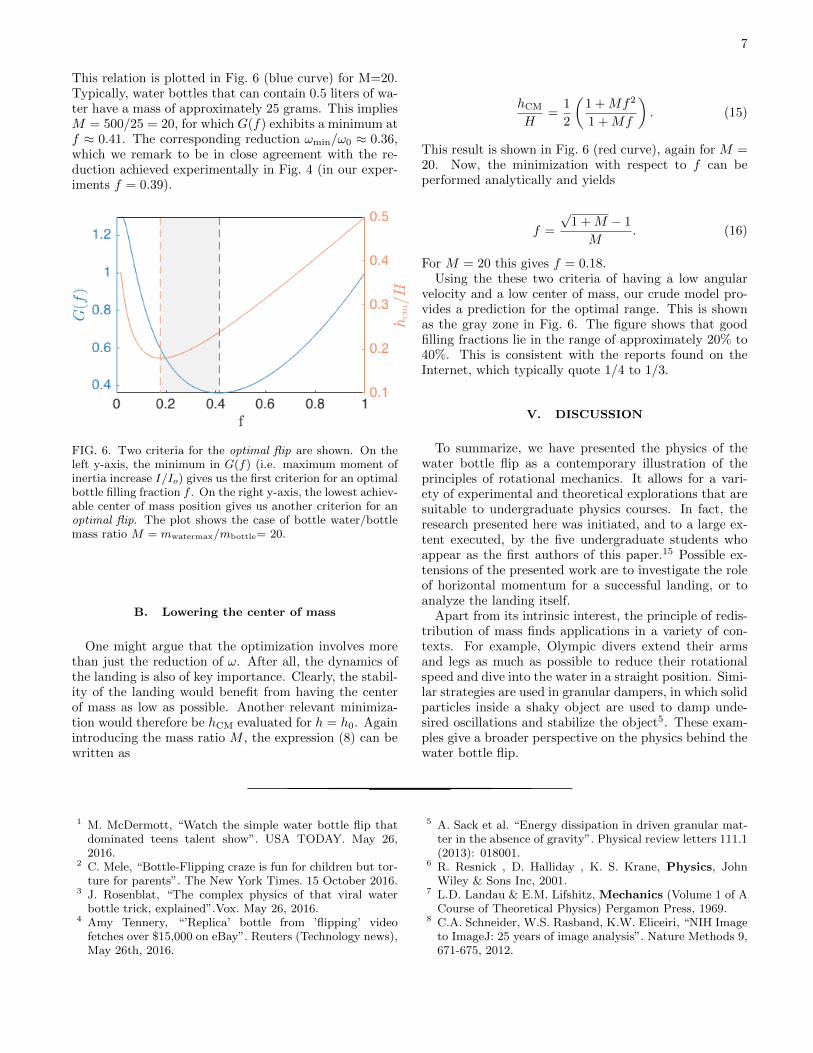
This relation is plotted in Fig. 6 (blue curve) for M=20.Typically, water bottles that can contain 0.5 liters of wa-ter have a mass of approximately 25 grams. This impliesM = 500/25 = 20, for which G(f) exhibits a minimum atf ≈ 0.41. The corresponding reduction ωmin/ω0 ≈ 0.36,which we remark to be in close agreement with the re-duction achieved experimentally in Fig. 4 (in our exper-iments f = 0.39).
FIG. 6. Two criteria for the optimal flip are shown. On theleft y-axis, the minimum in G(f) (i.e. maximum moment ofinertia increase I/Io) gives us the first criterion for an optimalbottle filling fraction f . On the right y-axis, the lowest achiev-able center of mass position gives us another criterion for anoptimal flip. The plot shows the case of bottle water/bottlemass ratio M = mwatermax/mbottle= 20.
B. Lowering the center of mass
One might argue that the optimization involves morethan just the reduction of ω. After all, the dynamics ofthe landing is also of key importance. Clearly, the stabil-ity of the landing would benefit from having the centerof mass as low as possible. Another relevant minimiza-tion would therefore be hCM evaluated for h = h0. Againintroducing the mass ratio M , the expression (8) can bewritten as
hCM
H=
1
2
(1 +Mf2
1 +Mf
). (15)
This result is shown in Fig. 6 (red curve), again for M =20. Now, the minimization with respect to f can beperformed analytically and yields
f =
√1 +M − 1
M. (16)
For M = 20 this gives f = 0.18.Using the these two criteria of having a low angular
velocity and a low center of mass, our crude model pro-vides a prediction for the optimal range. This is shownas the gray zone in Fig. 6. The figure shows that goodfilling fractions lie in the range of approximately 20% to40%. This is consistent with the reports found on theInternet, which typically quote 1/4 to 1/3.
V. DISCUSSION
To summarize, we have presented the physics of thewater bottle flip as a contemporary illustration of theprinciples of rotational mechanics. It allows for a vari-ety of experimental and theoretical explorations that aresuitable to undergraduate physics courses. In fact, theresearch presented here was initiated, and to a large ex-tent executed, by the five undergraduate students whoappear as the first authors of this paper.15 Possible ex-tensions of the presented work are to investigate the roleof horizontal momentum for a successful landing, or toanalyze the landing itself.
Apart from its intrinsic interest, the principle of redis-tribution of mass finds applications in a variety of con-texts. For example, Olympic divers extend their armsand legs as much as possible to reduce their rotationalspeed and dive into the water in a straight position. Simi-lar strategies are used in granular dampers, in which solidparticles inside a shaky object are used to damp unde-sired oscillations and stabilize the object5. These exam-ples give a broader perspective on the physics behind thewater bottle flip.
1 M. McDermott, “Watch the simple water bottle flip thatdominated teens talent show”. USA TODAY. May 26,2016.
2 C. Mele, “Bottle-Flipping craze is fun for children but tor-ture for parents”. The New York Times. 15 October 2016.
3 J. Rosenblat, “The complex physics of that viral waterbottle trick, explained”.Vox. May 26, 2016.
4 Amy Tennery, “’Replica’ bottle from ’flipping’ videofetches over $15,000 on eBay”. Reuters (Technology news),May 26th, 2016.
5 A. Sack et al. “Energy dissipation in driven granular mat-ter in the absence of gravity”. Physical review letters 111.1(2013): 018001.
6 R. Resnick , D. Halliday , K. S. Krane, Physics, JohnWiley & Sons Inc, 2001.
7 L.D. Landau & E.M. Lifshitz, Mechanics (Volume 1 of ACourse of Theoretical Physics) Pergamon Press, 1969.
8 C.A. Schneider, W.S. Rasband, K.W. Eliceiri, “NIH Imageto ImageJ: 25 years of image analysis”. Nature Methods 9,671-675, 2012.
8
9 MATLAB 2015b, The MathWorks, Natick, 2015.10 Wolfram Research, Inc., Mathematica, Champaign, IL
(2017).11 Maple. Maplesoft, a division of Waterloo Maple Inc., Wa-
terloo, Ontario.12 R. D. Kaufman, The electric cat: Rotation without overall
spin, Am. J. Phys. 81, 2 (2013)13 C. Frohlich, Do springboard divers violate angular momen-
tum conservation?. Am. J. Phys. 47.7, 583-592,(1979).14 See supplementary video footage.15 The research project was part of a course on classical me-
chanics, in the first year of the BSc program on AppliedPhysics at the University of Twente.


![[Rocketry].[Water Bottle Rocket Handbook]](https://img.pdfslide.us/doc/110x75/553e2eac4a7959bd2c8b4894/rocketrywater-bottle-rocket-handbook.jpg)