Embed Size (px)
Citation preview

Water and
Environmental Technology

2

Tested for the Toughest Applications 4
Automate Independently 6
Connect Flexibly 7
WAGO-I/O-SYSTEM 8
Wastewater Management 10
Water Resource Management 12
Control System Connection 14
Wireless Communication 16
Pump Control, Monitoring and Visualization 18
Current and Energy Measurement Technology 20
JUMPFLEX® 22
EPSITRON® 24
Software 26
Solution Package 28
Contents
3

DIN-Rail-Mount Terminal Block System
WAGO-I/O-SYSTEM
Proven quality thanks to certified processes and products:
• DIN ISO 90001:2008• ISO 14001:2004• DIN EN ISO 50001• IRIS Certificate• And many more
Tested for the
Toughest Applications
EMC tests
Quality results from experience and uncompromising attention to detail:
• Maintenance-free spring pressure connection technology• WAGO quality standards surpass those required by industry• All WAGO products undergo extensive testing• In-house EMC laboratory tests for electromagnetic compatibility
4
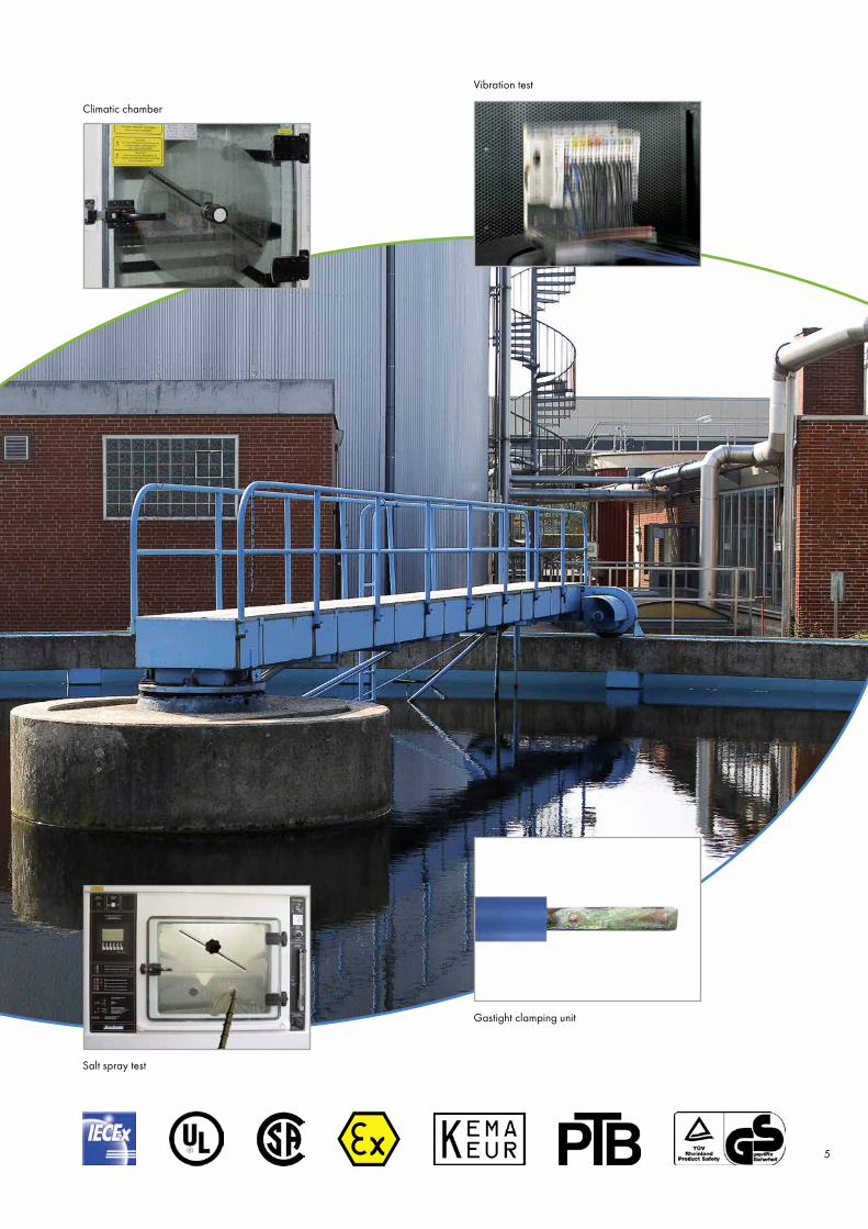
Vibration test
Gastight clamping unit
Salt spray test
Climatic chamber
5

Automate
Independently
Flexible, fieldbus- independent solutions for decentralized automation
Having a choice among our diverse WAGO-I/O-SYSTEM platforms, broad portfolio of relay, function and interface modules, as well as multiple overvoltage protection solutions, means you will always have the right option for your application.
Compact & modular:• Most compact, fieldbus-
independent controller (PLC)• Scalable performance — modular
controllers, control panels, IPCs• Programmable to IEC 61131-3• 400+ I/O modules available• Different potentials can be supplied
within one node Flexible & universal:• Support all standard fieldbus protocols • Compatible with IEC 60870 and
IEC 61850 telecontrol protocols• TO-PASS® telecontrol solutions• Combine standard I/O and Ex i modules• Safety meets Ex i — functional safety
and Ex protection in one module• Large selection of function libraries
EPSITRON® Power Supplies
WAGO-I/O-SYSTEM 750
WAGO-I/O-SYSTEM 750 XTR
TO-PASS® Telecontrol Module
PERSPECTO® Panels
WAGO SPEEDWAY, Modular IP67 I/O-System
6

Connect Flexibly
DIN-Rail-Mount Terminal Block System from 0.14–185 mm2 (24 AWG–350 kcmil)
High-Current DIN-Rail-Mount Terminal Blocks, 185 mm2 (350 kcmil)
PUSH WIRE® Connectors for Junction Boxes
The largest DIN-rail-mount terminal block system up to 185 mm2 (350 kcmil) with spring pressure connection technologyOur comprehensive and high-performance product portfolio fulfills every need — from the smallest to the greatest challenges.
CAGE CLAMP® technology:• Gas-tight spring clamp connection• Vibration-proof and maintenance-free• Increased system uptime and reliability Vibration-proof, fast and maintenance-free:• TOPJOB® S and POWER CAGE CLAMP• Largest DIN-rail-mount terminal block
system, ranging from 0.14–185 mm2 (24 AWG–350 kcmil)
• Industry’s widest range of spring pressure terminal blocks
• Suitable for all conductor types• CAGE CLAMP® S push-in termination
of solid and ferruled conductors• Industry’s fastest and most cost-
effective marking system• Comprehensive jumper system
for virtually any application
JUMPFLEX® 857 and 2857 Series 7

WAGO-I/O-SYSTEM 750
One System for Every Application
• Scalable performance — modular controllers
• Fieldbus-independent — compatible with all standard fieldbus protocols
• Programmable to IEC 61131-3• Provides 400+ finely modular
I/O modules• Features pluggable connectors
(optional)• Simplifies integration into the IT world
via HTTP, SNTP, SNMP, FTP and more
• Extended temperature range• Carefully selected components and materials
for -20 °C to +60 °C operating range
• Supports IEC 60870-5-101/-103/- 104, IEC 61850, IEC 61400-25 and MODBUS telecontrol protocols
• Maximizes return on investment• Boasts the best price/performance ratio • Enables custom node configurations• Saves space • Increases operational reliability• Decreases maintenance costs
The ideal control system:
8

• From 0 °C to -55 °C• Ex and non-Ex modules can
be combined in one node
eXTReme temperature from -40 °C to +70 °C
eXTReme isolation up to 5 kV impulse voltage
DIN EN 60870-2-1
eXTReme vibration up to 5g acceleration
DIN EN 60068-2-6
TAKING IT TO THE EXTREME — THE STANDARD FOR 750 XTR
9

Motor
M
Wastewater Management
Sewage Treatment Plant
Level measurement with TO-PASS®
Compact GSM/GPRS communication
Page 17
Outlet pumping station, control, condition monitoring and
energy measurement Pages 18–21
PLC
= GSM/GPRS
= Bluetooth®
Condition monitoring
Pumping station
= PROFIBUS
= Unspecific line= ETHERNET
HART
w
10

°C
DI/DO M
BAR
Motor
MPumpe
Requirements for wastewater plant components:• Robust system technology• Perform in extreme environments • System network applications • Remote monitoring• Easy to service• Highly flexible automation technology
• Support standard fieldbus systems• Connection to control system• Multiple interfaces• Streamlined connection to sensors• Use in hazardous areas
TOPJOB® S DIN-rail-mount terminal blocks:• All through and ground conductor
terminal blocks in the TOPJOB® S DIN-rail-mount terminal block line, as well as the special Ex high-current terminal blocks, are suitable for use in Ex e I/II areas.
• The X-COM®S-SYSTEM, which combines pluggable DIN-rail-mount terminal blocks and female plugs, is available for Ex applications in Zone 2 (“nA” ignition protection class).
Motor Pump
Pumping station
Zone 2Zone 22
Zone 21
Zone 20
Zone 1
WAGO-I/O-SYSTEM
Zone 0
Non-hazardous environment
Hazardous environment
Engineered for hazardous environments:• Approved for use in
Zone 2/22 and mining• Ex i I/O modules connect to
intrinsically safe sensors/actuators• Certified to ATEX, IECEx,
UL ANSI/ISA 12.12.01, UL508, shipbuilding, GOST-R, etc.
• All-in-one module — functional safety and explosion protection
11

M BAR
pH
DI/DO
BAR
pH
DI/DO
Water Resource Management
Process Water Treatment
230/24 V
24 V
HART
= ETHERNET
24 V 24 V
= System bus
= Unspecific line
12

pH
DI/DO
WAGO-I/O-SYSTEM 750 — PFC200:• Scalable solutions ranging from compact
controllers to advanced turnkey systems• Specialty functions: condition monitoring,
radio technology and more• Free function blocks for water
resource management
WAGO SPEEDWAY 767:• IP67 cabinet-free automation solution• Ideal for harsh environments —
Temperature range of -25 °C to +60 °C• Excellent protection —
Withstand EMC, water and dust
EPSITRON® — Advanced Power Supply System, 787 Series:• ECO Power and PRO Power Supplies
in single- and three-phase versions• Buffer modules• UPS
WAGO Switches, 852 Series• From the ECO Switch to the
Industrial Managed Switch• Fully compliant with IEEE802.3,
802.3u stantards
WAGO PERSPECTO®:• Monitors and panels• Monitor sizes from 3.5” to 15”• Multiple interfaces
24 V
HART
24 V
• Robust system technology• Use in system network and as
an all-in-one network solution • Highly flexible automation technology• Support standard fieldbus systems• Connection to control system
• Integration into industrial environments
• Remote monitoring• Multiple interfaces• Worldwide approvals
Requirements for components used in water treatment systems:
13

SPS
High-performance connection to a control system Control system connections are crucial for seamlessly monitoring waterworks or sewage treatment plants. Connect-ing both remote stations (e.g., wells, elevated tanks, pumping stations) and sewer system is required to streamline
the entire sewage treatment process. Communication is performed using standard bus protocols, as well as IEC 60870-5-101/-103/-104 telecontrol protocols and GSM/GPRS networks.
Control System Connection
Con
trol s
yste
mSy
stem
net
wor
ks
Office PCs
Printer
Central control unit
Pumping station Elevated tank Deep well
Standby phone
GSM modem
FirewallOperating and super- vising unit
EDG
E/U
MTS
HART communication
RS-485
PROFIBUS
ETHERNET
ETHERNETTCP/IP
PLC
MODBUS/TCP
14

WAGO Telecontrol Gateway• Connect up to 64 telecontrol substa-
tions with up to two control systems per IEC 60870-5-101/-104
• Communication per IEC 60870-5-101/-103/-104
• Connect substations via GSM, dedicated or dial-up line
• No control system limiting the number of connections
• Easy parameterization via Web-based management
• Transmitted data requires no parameterization
• Optional redundancy
MODBUS IEC 60870-5-101 / -103 / -104, 61850, 61400
Con
trol l
evel
Tran
smiss
ion
leve
lFi
eld
leve
l
Transmission per IEC 60870-5-104
via IPSec VPN tunnel
GSM Modem connection
1−16 telecontrol substations with modem connection
1−64 telecontrol substations
Transmission per IEC 60870-5-101/-103/-104
Transmission per IEC 60870-5-101/-103/-104
WAGO Telecontrol Gateway per IEC 60870-5-104 and IEC 60870-5-101
Web-based management
WAGO Telecontrol Gateway “light” for up to 16 substations
Configuration:
Router with fixed IP
15

750-
833
W
RUN
BF
DIA
I/O
PROFIBUS
BUS
USR
Wireless Communication
Wireless Technology
Range up to 400 m: • Robust and maintenance-free
cable substitute (IP65 degree of protection and internal antenna)
• Easy configuration
Range up to 1000 m: • Expansion within the WAGO-I/O-SYSTEM• Easy to use as multiplexer• Optional fieldbus connection
Range up to 1000 m: • Expansion within the WAGO-I/O-SYSTEM• Up to eight devices in a wireless network• Create extensive networks• Optional fieldbus connection
Point-to-point IP65 communication
Point-to-point IP20 communication
Multipoint IP20 communication
ETHERNET
Slave
Master 1 Master 2
Network 1 Network 2
Slave 1/1 … …Slave 1/7 Slave 2/1 Slave 2/7
Master
ETHERNET
WLAN
24 VDC24 VDC
16

GSM/GPRS
TO-PASS® Compact:• Rugged, compact device rated
for -20 °C to +70 °C operation• Cyclic and/or event-controlled
data transmission • Send fault messages to the
maintenance department• Send process data via GSM/GPRS
directly to the control center
• Configuring instead of programming• Connection to control center via com-
plimentary SQL data bank• Optional outdoor versions in IP66
housing with battery, charging control-ler and heater
TO-PASS® Web Connector:• Fieldbus-independent connection
of TO-PASS® Compact to the control system
• Send fault and event messages via GPRS data string (<1 KB) to a WAGO I/O controller with fixed IP address
• Transmit data (e.g., via MODBUS/TCP, BACnet, IEC telecontrol protocols per 60870, 61850, 61400) to a central control system
• Direct display via Web visualization
GSM/GPRS
Error reporting and networking for pumping stations and control center
TO-PASS® Compact: • 4 DI to 8 DI and 8 AI• Data logger function• Direct server connection• Optional use of
TO-PASS® Web Portal
GSM/GPRS
GSM/GPRS
GSM/GPRS
TO-PASS® Web Connector IEC 60870-5-101/-104
Control center
17

Pump Control, Monitoring
Powerful control• Scalable, modular control system• 400+ function modules• Memory expansion up to 32 GB (optional)• High system uptime• Remote connection• Combine specialty functions
Condition monitoring• Integrable vibration monitoring• Current and energy measurement• Temperature monitoring
Pumping stations are an essential part of both water/wastewater management and process industry infrastructures These factors are vital to continuously monitoring and optimizing these systems:
• Easy to service• Preventive maintenance• Integrable current and energy measurement technology • Future-oriented and reliable planning
WAGO-I/O-SYSTEM 750
Current and Energy Measurement Technology
18

and Visualization
Pump controlWAGO “Water.lib” and “Process.lib” function libraries• Minimal programming• Free pump function blocks• Data logger• Complete visualization
Detailed displays• Energy data visualization• Harmonic analysis
(up to the 41st harmonic)• Trend view
EPSITRON® — Uninterruptible Power Supplies (UPS) Reliably endure longer power failures with a UPS charger, controller and connected battery modules; features integrated battery control technology.
19

L1
+US
-US
CD
B
A
CD
B
A
C
DB
A
C
DB
A
L1
CD
B
A
CD
B
A
C
DB
A
C
DB
A
Current and Energy Measurement Technology
Transparency Pays Dividends
0–20 mA
Current transformer 250 A/1 A
DO/Alarm indication 24 V/100 mA
Power supply
PLC
0–20 mA
Rogowski coil
DO/Alarm indication 24 V/100 mA
Power supply
PLC
RT 500 (500 A)
Rogowski Transducer, 857-552
Current Transducer, 857-550
• Comprehensive network analysis• Streamline supply lines when up-
grading systems of the same type• Create transparency by switching
off consumers (e.g., ventilation)• Early detection and elimination of
asymmetrical network loads (e.g., due to insufficient compensation)
• Identify/avoid expensive peak load times by perfectly timing the switch off of secondary consumers
Identify, Optimize and Economize Energy Consumption
20

Visualization
I-S2
I-S2
I-S2
k-S1
k-S1
k-S1
PENL3L2L1
Terminal block assembly for current transformers, 2007-8873
Connecting current transformers to 3-phase power measurement modules
Measured variables:• Energy consumption• Voltage• Electricity• Phase position• Active energy/power• Reactive power/energy• Apparent power/energy• cos ϕ• Rotary field detection• Power factor• Four-quadrant operation• Harmonic analysis
(up to the 41st harmonic)• N-conductor measurement
These and other solutions can be found online: www.global.wago.com/en/solutions/current-energy-measurement-technology 21

JUMPFLEX® — 857 and 2857 Series
New Features for a Variety of Combinations
Industry’s Most Compact“True” 6.0 mm width maximizes
panel space.
Commoning, Not Discrete WiringSame outline allows use of a single
in-line, push-in jumper.
Always AccurateResistor laser trimming eliminates
recalibration.
Flexibility at its FinestConfigure via DIP switch or FDT/DTM
configuration tool.
For Extreme TemperaturesExtended temperature range of
-25 °C to +70 °C suits more applications.
Maximum SafetyAll devices provide “safe isolation” with
2.5 kV test voltage acc. EN 61140.
857 Series2857 Series
The 2857 Series was driven by customers’ needs for system planning flexibility and maintaining consistency. To achieve this, the 2857 Series’ housing was designed with the same shape as the popular 857 Series while spanning all widths.
The advantage rests in the palm of your hand: There is no need to wire each individual component thanks to push-in jumpers, which saves time and effort. This combination of mechanical and electrical characteristics has lead to unique features that continue setting the standard for transducers.
22
CD
B
A
CD
B
A
C
DB
A
C
DB
A
= >
= > 12 11 13
12 11 13
JUMPFLEX® — 857 and 2857 Series
New Features for a Variety of Combinations
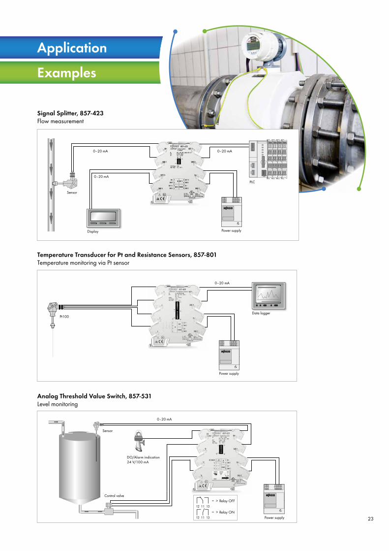
Application
Examples
Signal Splitter, 857-423Flow measurement
0–20 mA 0–20 mA
0–20 mA
Sensor
Display Power supply
PLC
Temperature Transducer for Pt and Resistance Sensors, 857-801Temperature monitoring via Pt sensor
0–20 mA
Power supply
Data loggerPt100
Analog Threshold Value Switch, 857-531Level monitoring
0–20 mA
Control valveRelay OFF
Relay ONPower supply
Sensor
DO/Alarm indication24 V/100 mA
23

EPSITRON® CLASSIC Power Single-phase power supplies with a wide input voltage range and 12 V, 24 V or 48 V output voltage.
EPSITRON® PRO Power Single- and three-phase power supplies with a wide input voltage range and 12 V, 24 V or 48 V output voltage. Features include PowerBoost, TopBoost and optional LineMonitor.
EPSITRON® COMPACT PowerLow-profile, single-phase power supplies with a wide input voltage range and 12 V/24 V output voltage.
EPSITRON® ECO Power Single- and three-phase power supplies with a wide input voltage range and 12 V, 24 V or 48 V output voltage. Features include Power- Boost, TopBoost and optional LineMonitor.
EPSITRON® — Advanced Industrial Power Supplies
The Right Solution for Every Application — 787 Series
24

EPSITRON® — Capacitive Buffer ModulesMaintenance-free, capacitive buffer modules provide reliable operation in the event of short voltage fluctuations.
EPSITRON® — Redundancy Modules Redundancy modules provide increased uptime and higher load current via two power supplies connected in parallel.
EPSITRON® — Electronic Circuit Breakers Configurable electronic circuit breakers protect up to four current paths, while providing both current and voltage monitoring.
EPSITRON® — Uninterruptible Power Supplies (UPS)Reliable compensation for longer power failures via UPS charger, controller and connected battery modules; features integrated battery control technology.
EPSITRON® — Advanced Industrial Power Supplies
The Right Solution for Every Application — 787 Series
25

Software
WAGO’s concept: Solution-oriented software modules
WAGO provides you with a series of software packages designed to make your daily work easier: No matter whether you are looking for programming and visualization tools, a software for operating and displaying a node, or configuration programs.
Programming/ Parameterization Hardware Service
26

V24V23
“Water.Lib” and “Process.Lib” function blocks
With free function libraries, WAGO offers you practical software modules for process technology applications:
• Support via software modules• Minimal programming • Easy to use • Easy implementation in
WAGO-I/O-PRO• Visual display elements• Customizable
PLC — Programmable ETHERNET Fieldbus Controller, Multitasking 32-Bit CPU, 750-880
PFC200, ETHERNET, RS-232/-485, 750-880
PFC200, ETHERNET, RS-232/-485, CAN, PROFIBUS, 750-8206
The function modules include:
Process.lib• Pump control• Motor• Mixer• Agitator
Water.lib• Pump station• Surface management• Valve control• Raking• Ventilation• Counters• Limit value monitoring• Control function blocks
27

Your advantages with WAGO:
• Maximum flexibility • Low investment costs relative to overall functionality • Free, fully functional user application • Data storage in open CSV format • Open source solution package• Individual expansions and/or program modifications
The open-source solution package allows individual functionalities to be added at any time. Examples from our application notes:
• Transmission of process values /changes via SMS/email• Data exchange with SQL databases • Connection to control systems from different manufacturers • Connection to IT via SNMP • Value integration in Web server • And more
• Flexible-to-configure measurement signal acquisition• Recording up to 80 analog or digital signals• Individually processing recorded data, if required• Adding WAGO-I/O-SYSTEM 750 modules• Storing process data on a removable device• Visualizing recorded data• Displaying current value• Displaying the last 20 values/channels in tabular form• Displaying the last 100 values/channels in trend form
WAGO’s data logger provides the following options:
Solution Package
28

TO-PASS® Web Connector Solution Package provides the following options: • Fieldbus-independent connection of
TO-PASS® Compact to the control system• Send fault and event messages via
GPRS data string (<1 KB) to a WAGO I/O controller with fixed IP address
• Transmit data (e.g., via MODBUS/TCP, BACnet, IEC telecontrol protocols per 60870, 61850, 61400) to a central control system
HTT
P Request
HTTP Resp
onse
Your advantages with WAGO:
• Fieldbus-independent connection to the WAGO-I/O-SYSTEM
• Free, fully functional user application• Freely expand system and modify
programs as needed• Scalable solutions from controllers
to IPCs (depending on the number of remote stations)
TO-PASS® Web Connector
TO-PASS® Compact:
• Rugged, compact device rated for -20 °C to +70 °C operation• TO-PASS® GPRS modules are available with up to 8 DI, 8 AI, 4 DO, 2 AO and MODBUS• Cyclic and/or event-controlled transmission • Configuring instead of programming• Optional outdoor versions in IP66 housing with battery, charging controller and heater
or
GPRS
Solution
Package
29

Expertise• Connection technology• System automation• Telecontrol solutions• Ex applications• Signal conditioning
Support• Free hotline• Qualified fieldbus specialists• Troubleshooting
Support• Application notes• Assistance in preparing your bid• Function libraries• Help creating proposals• Planning and project engineering
Solutions• I/O system advisors• Application engineers
Training• CODESYS• Automation• Connection technology
Consulting • Concept creation• Component selection• Network planning• Application layout

• Rail-Mounted Terminal Blocks• Modular Connectors
(X-COM®-SYSTEM and X-COM®S-SYSTEM)
• Patchboard Systems
• Terminal Strips• PUSH WIRE® Connectors
for Junction Boxes• Lighting Connectors• Shield Connecting System
• PCB Terminal Blocks• Feedthrough Terminal Blocks• MULTI CONNECTION SYSTEM (MCS)• Pluggable PCB Terminal Blocks• Specialty Connectors
• IP20 Modular I/O-SYSTEMS• Radio Technology, TO-PASS®
Telecontrol Technology• Industrial Switches, PERSPECTO®
• IP67 Modular I/O-SYSTEM, IP67 Block I/O-SYSTEM
• IP67 Sensor/Actuator Boxes, IP67 Cables and Connectors
• Power Supplies
• Relays – Optocouplers – Specialty Functions
• Interface Modules• Transducers• Power Supplies
• Overvoltage Protection• Radio Technology• Empty Housings and
DIN-Rail Mount Carriers
• WINSTA® MINI – Pluggable Connectors• WINSTA® MINI special – Pluggable Connectors• WINSTA® MIDI – Pluggable Connectors• WINSTA® MIDI special – Pluggable Connectors• WINSTA® MAXI – Pluggable Connectors• WINSTA® RD – Cable Assemblies• WINSTA® KNX – Pluggable Connectors• WINSTA® IDC – Flat Cable Systems
Volume 1, Rail-Mounted Terminal Block Systems
Volume 2, Connectors and PCB Terminal Blocks
Volume 3, AUTOMATION
Volume 4, INTERFACE ELECTRONIC
Volume 5, WINSTA® – The Pluggable Connection System

0888
-018
2/02
00-6
901-
Bra
nch
Broc
hure
Wat
er 2
.0 U
S - 0
9/14
- Pr
inte
d in
Ger
man
y - S
ubje
ct to
des
ign
chan
ges
WAGO Kontakttechnik GmbH & Co. KGPostfach 28 80 · D - 32385 MindenHansastraße 27 · D - 32423 MindenGermanyPhone: +49 571 887- 0Fax: +49 571 887-169Email: [email protected]: www.wago.com