Embed Size (px)
Citation preview

treatment W in the CPI Expedient sludge processing can reduce many industrial waste-disposal problems. This study focuses on thickening and dewatering equipment, presenting design and operational parameters, and plant and laboratory peformance data.
BJF P Industries reviewed:
Organic chemicals c / I -
C] Petrochemicals Inorganic chemicals
C] Fine and pharmaceutical chemicals
0 Mineral processing Secondary-metals processing
0 pulp and paper
Processes covered: ,
0 Thickening. . . gravity and flotation Dewatering. . . centrifugition, atration and heat treatment Secondary treatment. . . aerobic and anaerobic dipstion
0 Chemical fixation Byproduct recovery
R. W Oh, D. Lh’Gregm*o and E. G. Kominck, Enuirotsch Gorp.
0 The chemical process industries (CPI) produce a great volume and variety of waste solids, which are separated as sludge from process waters and aqueous wastes. The sludge must be treated and prepared for environmentally sound disposal. Here is a cpr-wide review of operational principles and design approaches for sludge-processing equipment and techniques. Vol- ume reduction is the key to economical disposal and is the theme of this article.
A typical waste-processing flowsheet describing solids capture and concentration is shown in Fig. 1. Raw wastewater is treated in clarifiers specificallydesigned to provide a clear overflow, regardless of underflow con- centration. Primary sludge is defined as the liquid waste containing suspended material that remains after pri- mary clarification. The clear overflow is Sent to wet-line bioconversion and secondary clarification units, which produce secondary sludge. The primary sludge is the main focus of this article because it possesses a unique character that differs from industry to industry. The secondary sludge is basically waste-biological cell tissue and is generally similar for all industries.
Primary sludges vary widely in specific gravity,
a d particle size. However, some general classifications can be made. Table I lists primary sludges and waste Solids generated by the CPI.
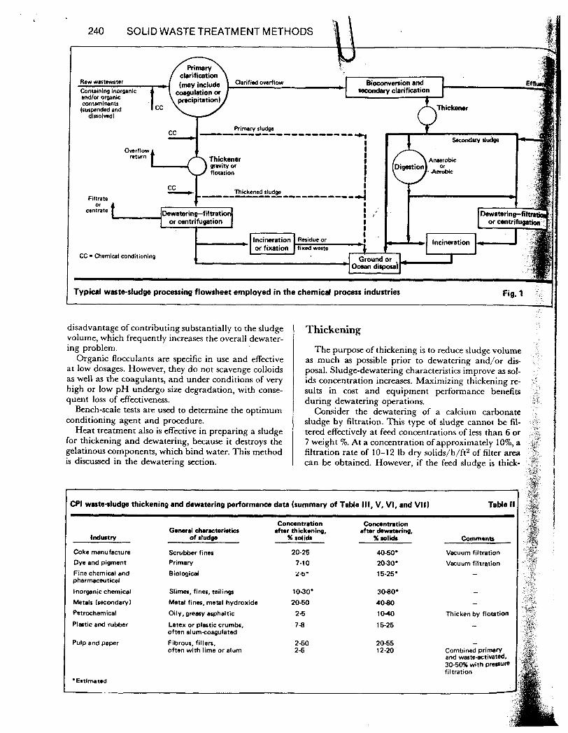
Table I1 lists thickening and dewatering performance data for sludges typically generated by certain indus- tries. Though available cost data are insufficient to
the various industries, thickening and dewater- ing usually cost about $10-$50/ton of dry solids.
Or1QlnallY Published January 29,1979.
chemical and biological stabilit)., n!ubi!ity,. texicitjj . .
Pretreatment Most sludges require chemical conditioning prior to
thickening and dewatering. Conditioners can be di- vided into two broad categories: inorganic coagulants, such as lime, hydrated aluminum sulfate (alum) and ferric salts; and organic flocculants, which have high molecular weight and are cationic, anionic or nonionic.
Inorganic coagulants have widespread use, and in most cases effectively capture colloids. They have the
Solid-wastes generated in the C p I Table I
Coke manufacture
Dyes end p m n n
Finechemical and pharmaceutical Inorganic chemicals
Metal processing ~recondary)
Petroc)Mmicrl PlDltiC and Nbber
Pulp and paper
Coke and coal fiw
Reaction or raw- material sludge, hiehly variable Fhwnaterial rolidr, - bidogkal “s IMduble dtl. - tailings. rl!mr, Ash,rcrubber wastes, metal hydroxide sludfp8 Oily, greasy,asphaltic Usually float Latex or plastic - crumb, oftan alum coagulated Flbrwr; w e fine filter. ofnn with lime or alum
Generally contained in scrubber wmtsr -
-
-
239
Annrobic
-Aerobic
Typical waste-sludge processing flowsheet employed in the chemical process industria Fig. 1
disadvantage of contributing substantially to the sludge volume, which frequently increases the overall dewater- ing problem.
Organic flocculants are specific in use and effective at low dosages. However, they do not scavenge colloids as well as the coagulants, and under conditions of very high or low p H undergo size degradation, with conse- quent loss of effectiveness.
Bench-scaie tests are used to determine the optimum conditioning agent and procedure.
Heat treatment also is effective in preparing a sludge for thickening and dewatering, because it destroys the gelatinous components, which bind water. This method is discussed in the dewatering section.
Thickening
The purpose of thickening is to reduce sludge volume as much as possible prior to dewatering and/or dis- posal. Sludge-dewatering characteristics improve as sol- ids concentration increases. Maximizing thickening re- sults in cost and equipment performance benefits during dewatering operations.
Consider the dewatering of a calcium carbonate sludge by filtration. This type of sludge cannot be fil- tered effectively at feed concentrations of less than 6 or 7 weight %. At a concentration of approximately IO%, a filtration rate of 10-12 Ib dry solids/h/ft* of filter area can be obtained. However, if the feed sludge is thick-
:PI waste-sludge thickening and dewatering performance data (summary of Table 111, V, VI, and VII) Table II
Conantration Conantration General charrtrristics after thickening, after &wetoring,
Industry of sludgo % solids %rolids Comments
Coke manufacture Scrubber fines 20-25 40-50' Vacuum filtration
Dye and pigment Primary 7-10 2030' Vacuum filtration Fine chsmicd snb Bioiqicai pharmaceutical
26' 15-25, -
Inorganic chemical Slimes, fines, tailings 10-30' 30-80' - Metals (secondary) Metal fines, metal hydroxide 20-50 40-80 - Petrochemical Oily, greasy asphaltic 2-5 1040 Thicken by flotation
Plastic and rubber Latex or plastic crumbs, 7 8 often alumcoagulated
Pulp and paper
*Estlmat.d
Fibrous, fillers, often with lime or alum
2-50 2-5
15-25
20-55 - 12-20 Combined primary
and waste-ectivatd. 30-50% with preoum filtration
20-55 - 12-20 Combined primary
and waste-ectivatd. 30-50% with preoum filtration
WASTE-SLUDGETREATMENT IN THE CPI 241
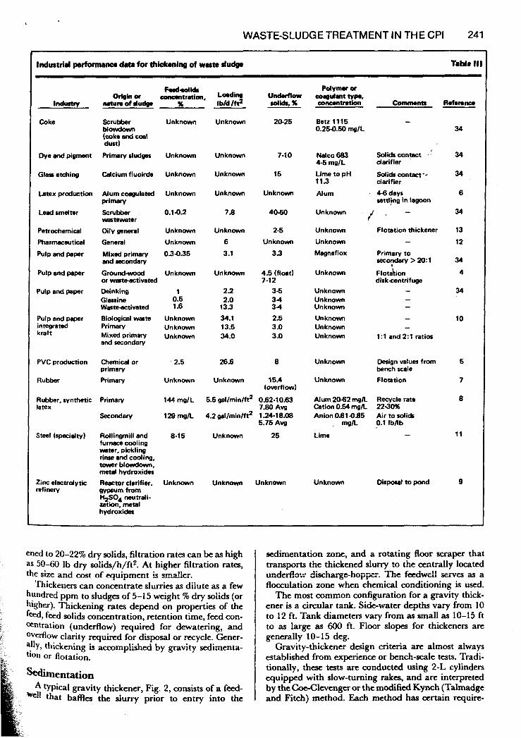
Industrid perform~lco data for thickening of waste dudp
lndurty
Coke
Dye and pigment
Glass etching
Latex production
Lead smelter
Petrochemical
Pharmaceutical
Pulp and paper
Pulp and paper
Pulp and paper
Pulp and paper integrated kraft
PVC production
Rubber
Rubber. synthetic latex
Steel (rpecielty)
Zinc electrdytic refinery
F d d i d S Oeinor -won, Lading
Mtursofdudg. x I bld lftl
Scrubber Unknown Unknown M o w d O W (coke and coal dust)
Primary sludges
Mcium fluoirde
Alum coagulated primary
Scrubber wastewater
Oily general
General
Mixed primary and Secondary
G r o u n d d or wcrteativated Deinking Glassine Waste-activated Biological waste Primary Mixed primary and secondary
Chemical or primary Primary
Primary
Secondary
Rdlingmill and furnace cooling water, pickling rinse and cooling, tower blowdown, metal hydroxides
Reactor clarifier. gypsum from %SO4 neutrali- zation, metal hydroxides
Unknown
Unknown
Unknown
0.142
Unknown
Unknown
034.35
Unknown
1 0.5 1.6
Unknown Unknown Unknown
' 2.5
Unknown
144 mglL
129 mdL
8-1 5
Unknown
Unknown
Unknown
Unknown
7.8
Unknown
6
3.1
Unknown
2 1 2.0
133 34.1 13.5 34.0
26.6
Unknown
Und.rf i0W rolidS, x
20-25
7-10
15
Unknown
4060
2-5
Unknown
3.3
4.5 (float) 7-12
3-5 3 4 3 4
2.5 3 .O 3 .O
8
15.4 (overflow)
5.5 gallmintft2 0.62-10~3
4.2 gallmin/ft2 1.24-18.08 7.80 Avg
5.75 Avg
Unknown 25
Unknown Unknown
Bet2 11 15 - 0.25-0.50 mg1L
Nako 683 4-6 mglL
Lime to pH 113
Alum
Unknown
Unknown
Unknown
Magnaflox
Unknown
Unknown Unknown Unknown
Unknown Unknown Unknown
Unknown
Unknown
Solids conpct I
clarifier
Solids contact-* darifier
4-6 days settljng in lagoon
Flotation thickener -
Primary to secydary > 20: 1
Flotabon dirkcentrifuge
- - -
- 1:l and 2:l ratios
Design values from bench wale
Flotation
Alum 20.62 mgA Recycle rate Cation 0.54 mgA 2240% Anion0.61-0.85 Air to solids
Lime
mgA 0.1 IbAb -
Unknown Disposal to pond
34
34
34
6
34
13
12
34 4
34
10
5
7
8
11
9
ened to 20-22% dry solids, filtration rates can be as high as 50-60 Ib dry solids/h/ft*. At higher filtration rates, the size and m s t of equipment h rma!!er.
Thickeners can concentrate slurries as dilute as a few hundred ppm to sludges of 5-15 weight % dry solids (or higher). Thickening rates depend on properties of the feed, feed solids concentration, retention time, feed con- centration (underflow) required for dewatering, and overflow clarity required for disposal or recycle. Gener- ally, thickening is accomplished by gravity sedimenta- tion or flotation.
Sedimentation A typical gravity thickener, Fig. 2, consists of a fd-
that baffles the slurry prior to entry into the
sedimentation zone, and a rotating floor scraper that transports the thickened slurry to the centrally located
flocculation zone when chemical conditioning is used. The most common configuration for a gravity thick-
ener is a circular tank. Side-water depths vary from 10 to 12 ft. Tank diameters vary from as small as 10-15 ft to as large as 600 ft. Floor slopes for thickeners are generally 10- 15 deg.
Gravity-thickener design criteria are almost always established from experience or bench-scale tests. Tradi- tionally, these tests are conducted using 2-L cylinders equipped with slow-turning rakes, and are interpreted by the Coe-Clevengu or the modified Kynch (Talmadge and Fitch) method. Each method has certain q u i r e -
u d d o w di.har@oppi. '%e fe&dl SFXS s 8

242 SOLID WASTE TREATMENT METHODS ments that must be met, which involve selecting an operating point on a settling curve to calculate thick- ener sizing. These tests are also useful in predicting overflow clarity, underflow solids content, and the effi- cacy of chemical flocculants.
Gravity thickening of organic sludges (particularly waste-activated sludge) is complicated by anaerobic action. If the temperature is warm, bacteria in the sludge will decompose organic matter, releasing gases. This causes flotation problems, hinders compaction and creates noxious odors. Sedimentation-thickener load- ings for organic sludges range from 4 to 12 Ib/d/ft', while flotation thickening can handle loading rates of 36 to 48 lb/d/ft2.
Flotation Flotation thickening is used for slurries containing
solids that float rather than settle, or have slow settling rates or poor compaction. Flotation keeps the system aerobic. A typical dissolved-air-flotation (DAF) thickener is shown in Fig. 3. Most flotation thickeners use recycle pressurization. Part of the flotator subnatant is pressur- ized. The incoming feed does not pass through the pressurization system but rather is mixed with pressur- ized recycle in the inlet-diffuser.
Flotation thickeners are rectangular or circular. Standard rectangular flotators vary in size from 100 ft' to as large as 1,800 ft2. Rectangular flotators are usually used for small applications and where space considera- tions are paramount. Both types are equipped with surface skimmers and floor rakes. The surface skimmers remove float from the thickening tank to a float sump.
Lifting devi- (Feed launder
It Arm, I lades
Discharge cone -
Gravity thickener Fig. 2
Dissolved-air flotation unit with recycle flow-pressurization Fig. 3
b
WASTE-SLUDGE TREATMENT IN THE CPI 243
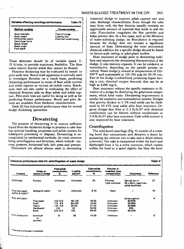
Variables affecting centrifuge performance TaMe IV I I 1 kchit" variables Pmcos vari.bla
Bowl diameter Bowl length Differential speed Centrifugal force Beach length Beach angle Pool depth
Type of sludge Loading rate Chemical conditioning
These skimmers should be of variable speed, 2- 25 ft/min, to provide maximum flexibility. The floor rakes remove heavier solids that cannot be floated.
Flotation thickening may be evaluated by bench- or pilot-scale tests. Bench-scale apparatus is normally used to investigate flotation on a batch basis, predicting thickening performance in terms of float solids content and solids capture at various air/solids ratios. Bench- scale tests are also useful in evaluating the effect of chemical flotation aids on float solids and solids cap- ture. Pilot-scale tests are useful for sizing as well as for predicting flotator performance. Bench and pilot de- vices are available from thickener manufacturers.
Table I11 lists industrial performance data for several sludge thickening operations.
Dewatering The purpose of dewatering is to remove sufficient
liquid from the thickened sludge to produce a cake that has optimal handling properties and solids content for subsequent processing or disposal. Dewatering is ac- complished by mechanical methods, the most common being centrifugation and filtration, which include: vac- uum, pressure, horizontal belt, belt press and precoat.
Flocculants are almost always used in dewatering
Industrial performance data for centrifugation of was- sludge
industrial sludge to improve solids capture rate and cake discharge characteristics. Even though the cake may form well, the fine fraction usually contains an appreciable amount of material that tends to seal the cake. Flocculation coagulates the fine particles and helps prevent this. In a few cases, such as the filtration of water-softening sludge, no flocculation is required because the sludge does not contain a significant amount of fines. Determining the most economical chemical addition for a specific sludge should be based on bench-scale testing or pilot-plant studies.
Heat treatment of sludge prior to dewatering stabi- lizes and improves the dewatering %haracteristics of the sludge. It also destroys organics. It can be oxidative or nonoxidative, depending .on the specific process in- volved. Waste sludge is treated at temperatures of 350- 450°F and maintaingd at 150-250 psig for 20-30 min. Part of the sludge is solubilized, producing liquor hav- ing a COD, chemical oxygen demand, that can be as high as 4,000 mg/L.
Heat treatment reduces, the specific resistance to fil- tration of a sludge by destroying the gelatinous compo- nents, which bind water. Dewatering improvement is similar for oxidative and nonoxidative systems. Sludges that gravity thicken to 2-3% total solids can be thick- ened to 10-15% total solids after heat treatment. Or- ganic sludges that filter at 2-3 Ib/h/ft2 with chemical conditioners can be filtered without conditioners at 5-8 Ib/h/ft2 after heat treatment. Cake solids content is also improved by heat treatment.
Centrifugation The solid-bowl centrifuge (Fig. 4) consists of a rotat-
ing bowl that concentrates and dewaters a slurry by separating the mixture into a cake and a dilute stream (centrate). The cake is transported within the bowl and discharged from it by a screw conveyor, which rotates within the bowl at a speed slightly less than the bowl
Table V
FWddidS Cakrdids Polymer or Origin or conantration, Loding concontration, coam~lant typo.
Industy naturo of rludg. x gdlmin x concontration Comnnnts R.fmnca
Chemicals Primary Unknown Unknown 35 Polymer Carried out in 21 type unknown 40 x 6W:n. machines,
solids Iandfilled
Pulp and paper Biological wte 1-2 sulfite & NSSC*
pulp and paper Fine paper 3.5-12.0 Kraft 1.0- 4.5 Tissue 1.0- 4.0 Hardboard 2 .o Book 6.0-12.0
pVC Production Chemical 8 or
primary
Unknown 8-10
56-120 1635 95320 1540 2038 2142 43 3035
150 4045
28 15-25
None - 16
solids CW" 4 Unknown 8085% Unknown 8085% Unknown 65- Unknown 85% Unknown 85-92%
Unknown - 5

? f
z
244 SOLID WASTE TREATMENT METHODS
Differential-speed Rotating .Cover
f gearbox I I I I I I
tl discharge discharge
I I Fig. 4 1
sped. The centrate overflows weirs on the opposite end of the bowl.
There are numerous machine and process variables that affect centrifuge performance. Table IV lists the most important ones.
The capacity of a centrifuge is related to its size (bowl diameter and length). During operation, a pool is formed in the inner periphery of the bowl. The pool volume is determined by the bowl diameter and length, and pool depth. For a specific loading, solids capture generally improves as pool volume increases.
If all variables remain Constant, an increase in the bowl diameter will increase pool volume and retention
Filter medium
Buic principle of the rotary- I drum vacuum filter Fig. 6
WASTE-SLUDGE TREATMENT IN THE CPI 245
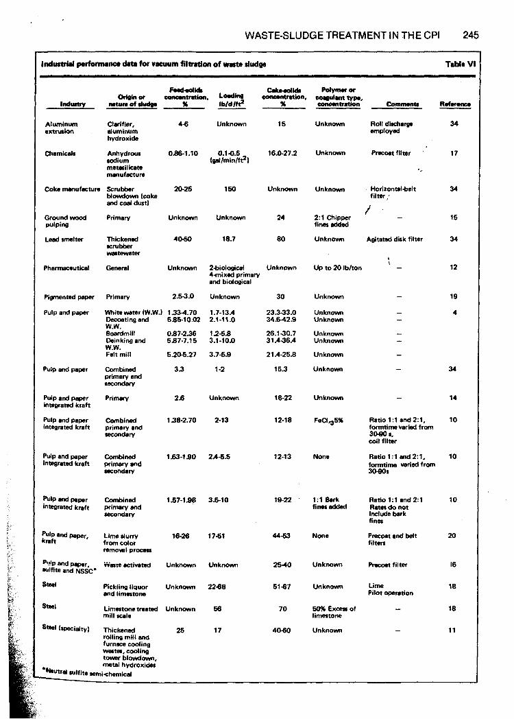
Industrial performmnco data for vacuum filtration of wato dud* Table VI
Aluminum Clarifier, 4 6 extrusion aluminum
hydroxide
sodium metasilicate manufacture
Mowdown (coke and coal dust1
Chemicals Anhydrous OM-1.10
Coke manufmxure Scrubber 20-25
Unknown 16 Unknown Roll dkcharga employed
34
17
34
15
34
12
19
4
34
14
10
10
10
20
16
18
18
11
0.14.5 16.0-27.2 (gat/min/f?I
Unknown Pracoat filter
150 Unknown Unknown . Horirontal4elt filter;
2: l Chipper 1 ‘ - fines added
Unknown AQitated dirk filter
Ground wood pulping
Lead smelter
Primary Unknown Unknown 24
18.7 80 Thickened 4o-!jo scrubber wastewater
General Unknown , - \
Up to 20 IbJton Pharmaceutical 24iological Unknown 4inixed primary and biological
Unknown
1.7-13.4 2.1-11.0
123.8 3.1 -10.0
3.78.9
1 -2
Unknown
2-13
2.4-5.5
3.6-10
1761
Unknown
2288
66
17
Primary 2.53.0
White water (W.W.1 1334.70 Decoating and 585-10.02 W.W. Boardmill 0.87-236 Deinking and 587-7.15 W.W. Felt mill 5.208.27
Combined 3 3 primary and secondary
Primary 2.6
Pigmented paper
Pulp and paper
30
23.333.0 34842.9
26.130.7 31.436.4
21 A-25.8
153
18-22
12-18
12-1 3
19-22
44-63
2540
6187
70
40-60
Unknown
Unknown Unknown
Unknown Unknown
Unknown
Unknown Pulp and papaf
Pulp and p e r integrated kraft
Pulp and paper integrated kraft
Unknown
Combined 138-2.70 primary and secondary
FeClq5% Ratio 1 : 1 and 2: 1, formtimevaried from 3080 L, coil filter
Ratio1:l and2:1, fomtime varied from 30-90s
Pulp and paper integrated kraft
Combined 1.63-1 90 primary and = d r y
None
Pulp and paper integrated kraft
Combined 1.57-1.08 primary and =-ry
1:l Bark finer added
Ratio 1:l and 2:l Rates do not include bark fines
Precoat and belt filters
pulp end paper, kraft
Lime slurry 16-26 from color mmoval proms
i%sre activated Unknown
None
Unknown Precoet filter
Pickling liquor Unknown and limestone
Limestone treated Unknown mill scale
Unknown time Pilot operation
Steel 50% Excess of limestone
Unknown Thickened 25 rolling mill and furnece cooling wastes, cooling towar t?lowdown, matal hydroxides
246 SOLID WASTE TREATMENT METHODS
speeds sufficient to develop forces 1,000-3,000 times that of gravity. Increasing centrifugal force usually increases solids capture and cake solids content. How- ever, cake solids content may remain constant or even decrease, depending on the quantity and characteristics of the additional solids captured.
The solids forced t o the inner wall o f thc bowl are conveyed up the cone of the bowl, the beach, for discharge from the machine. 'The length and angle o f the beach have a strong influence on centrifuge per- forma nce, part icu I a rl y w i t h sl u dges con t ai n i r i g 1 i g ti t , gelatinous solids (waste-activated or metal hydroxide sludges). As the sludge is conveyed along the beach (especially where contact with the pool ceases), addi- tional moisture drains off prior t o discharge. For most sludges, incrcasing dry-beach residence time will in- crease cake solids content.
As the cake is corivc:yed along the lxach, i t is suh- jectcd to centrifugal force acting perpendicular to t tic bowl and to a f i ) r c ~ acting Ixirallel t o the t m d i . The parallel force tends t o push the solids down the beach into the pool. 'l'his "slippage" force is related t o the centrifugal force and the beach angle.
For sludges corisisting of light, gelatinous solids, thc slippage force can tx suliicicnt to cause conveyed solids t o flow under the conveyer blades back into the pool. Solids capture tirtcriorates i n this situation and centri- fuge capacity is sevcrcly liinited. Machines having srn;ill beach angles, or ~ ) o o l s raised t o slightly below the cakc discharge p i n t . can be used to overcome this problern.
'I'hc diffi.rencc i n rotational speed between the scrc\z' conveyor and thc bowl is termed the dilikrential speed. For a specific loading, it is advantageous t o maintain t he in i n i i n um d i fkrcn t i a l speed necessary t o convey all cake from the machine. Increasing differential speed above this level increases pool turbulence and speeds the cake conveying rate in the pool and on the beach. 'I'hese factors generally reduce solids capture, especially in applications involving waste-activated, nictal hy- droxide and other difficult sludges.
I he rna,jor process variables aliecting performance are the type o f sludge, the use of chemical llocculants, and the loading rate to the machine. For any applica- tion, loading rate and chemical conditioning can be varied to control centrifugc performance in terms of cakc solids content and solids recovery. Fig. 5 shows the norrnal relatioilship betwcen cake solids content arld solids recovery. 'l'his relationship can be controllc:d by changing process conditions (loading rate) and rnac:hinc. conditions (pool volurnc~ and dific:rcntial si~ecd).
Ccntril'uges ai-e t)cst sizcd lrom pilot- or ~)roto typt~- scale , ,.. .+.. I..., _-.. 1. -- .~
, , ~ ] C . I aiiiis ai iiic piantsite under a c i d con- ditions. When this is r i o t possible, perfornianc:c: m a y Ix: c s t iniated using batc ti la bora tory ccn t ri fuges. I'rocc- dures for conducting laboratory tests arc dc:scribc:d i n the literaturc I.3.Sl. Since tticsc: t(:sts arc hatch and do not includc provisions li)r wntinuous removal of settled solids f r o n i the pool, indirect nicthotis niust tic used I ( J
j udgc w h r t livr so I ids c;i I I I)(. srrcx~c~ssfu I 1 y d is(: t i i i i.gc~l t'rom f'u I I-sc,;r I C rnach i iivs. ' I ~ ti is is cssrn t i;i I . (;c.nc:r.a 11 y . granular solids (:an tx: reitdily cwnveycd out of' a l'ull- scale centrifugc, whcrcas lloc~.ulatcd ; i n d / o r cwrnprcssi- b le s o 1 ids a IC% sign i f i (:a ri t I y I i i (
? .
(I i I I ic. 11 I t .
xeen
of sol j from
~. . .**
ids SIUI
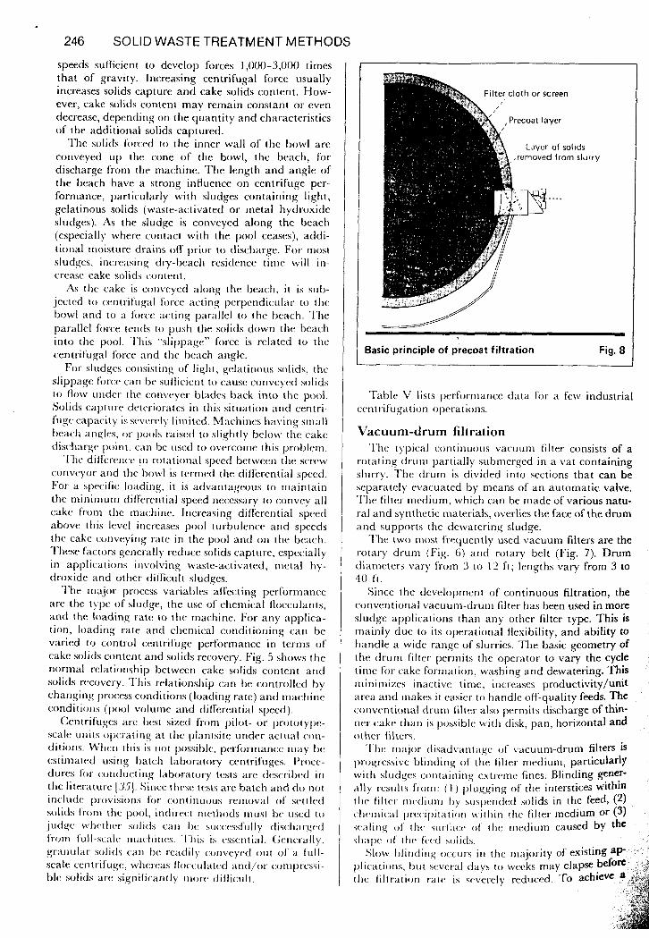
Basic principle of precoat filtration Fig. 8
'I-ahle V lists performance data for a few industrial centrifugation operations.
Vacuum-drum filtration The typical continuous vacuum filter consists of a
rotating drum partially submerged in a vat containing slurry. l l i e drum is divided into sections that can be separately evacuated by means of an automatic valve. The filter medium, which can be made of various natu- ral and synthetic materials, overlies the face of the drum and supports the dewatering sludge.
T h e two most frequently used vacuum filters are the rotary drum (Fig. 6) and rotary belt (Fig. 7). Drum dianietcrs vary from 3 t o 1'2 f t ; lengths vary from 3 to 40 f l .
Since the developnient of continuous filtration, the conventional vacuum-drum filter has been used in more sludge applications than any other filter type. This is mainly due to its operational flexibility, and ability to handle a wide range o f slurries. The basic geometry of the drum filter permits the operator to vary the cycle time for cake formation, washing and dewatering. This in i ni i n izes inactive time, i ricrcases productivity/unit arva and rnakes i t easic-r to handle off-quality feeds. The conventional di.crni filter also permits discharge of thin- ner- cake than is possiblr Lvitti disk, pan, horizontal and other filters.
'l'hc: major disadvant;igc 0 1 vacuum-drum filters is I)rogressive blinding o f the lilter medium, particularly with sludges c:ontaining extreme fines. Blinding gener- ;z\ly rcsiilts froni: ( I ) pluggirig of' the interstices Within t Iic filter r i i c d i u n i b y suspmded solids in the f e d , (2) c ~ l i c . i r i i c ~ t l l)r<,(,il>itiztioii wi t t i in the filter medium or (3) waIing 01' tiir s u i . ~ ' : i c ~ 01. t t i r riiediurn caused by the s l i a l x of t h c . frcd solids.

WASTE-SLUDGE TREATMENT IN THE CPI 247
-
II
Feed
Precoat liquid
--?=I+-
I Precoat material
Wash liquid 4
t Filtrate
-w f
1 To atmosphere
oat
Vacuum pump To drain 1
- - Filtrate Pump
L--t To process
'recoat filtration system for capturing fine solids that cannot be flocculated Fig. 9
balance between cloth life, operating time and capital cost, the design filtration rate must be 70-80% of the clean-medium rate. When blinding reaches a critical point, the medium must be replaced or rejuvenated with an acid or alkaline wash.
Another problem is poor cake-discharge. If a filter cake of minimum thickness and sufficient dryness is produced, the cake discharge will be practically com- plete. Generally, %-in. minimum thickness is desirable, although cakes of y8-in. can be discharged. However, if thin, slimy or moist cakes are encountered, cake dis- charge can be severely impaired. In addition, reduction in filter capacity, accelerated rate of blinding and dif- ficulty in cake removal can occur if multifilament weaves of cotton and other natural fibers are used in the filter medium, because short fibers imbed in the cake.
Use of a rotary-belt-type drum filter eliminates or greatly reduces problems of blinding and cake thick- ness. The design (Fig. 7) consists of a sectionalized d r m , in which the periphery of each section contains a Soft rubber or synthetic strip that is slightly raised from the drum surface. The filter medium lies over these strips, sealing the vacuum side from the atmosphere. Since a typical filter operates at a 20-25 in. Hg vacuum, there is approximately 10-1 2 Ib/in.2 of pressure provid-
sufficient sealing force. The filter medium is an endless belt that travels off the drum to a cake discharge
and then to a wash chamber, where fluid is applied through high-pressure sprays to both sides of the cloth. Occasionally, an acid wash may be required to reduce blinding.
Cake discharge is accomplished by passing the filter
medium over a small-diameter roller, which very ab- ruptly changes the radius of curvature of the medium relative to the cake, causing the cake to break free from the cloth. Generally, a scraper blade is not required to loosen the cake from the medium but rather to deflect the cake to the discharge point of the filter. Cakes as thin as Yl6 in. can be satisfactorily discharged.
Particulate sludges containing less than 50% of 200- mesh (74 microns) solids can be successfully handled by belt-type units, which can also handle most plating, steel mill, water softening, foundry, organic and phar- maceutical sludges, and even wet-air oxidation sludges.
Filtrate containing suspended-solids levels as low as 500 mg/L can be achieved with belt-type units, from feed concentrations as high as 10-20% solids. With other filters, such as precoat units, filtrate solids of only 25 mg/L or less are possible.
Vacuum-drum filtration may be evaluated from bench- or pilot-scale tests. Bench-scale apparatus proce- dures have been well developed and are described in the literature [SS], [37]. The filter-leaf method is useful for predicting filter performance under a variety of operat- ing conditions and for establishing medium type, bridging and submergence. Pilot-scale vacuum-drum filter tests are particularly useful in identifying and solving cake pickup and discharge problems.
Table VI lists performance data for several industrial vacuum-filtration operations.
Precoa t filtration Precoat vacuum filtration is used primarily for clari-
fication purposes or for difficult filtering applications in

248 SOLID WASTE TREATMENT METHODS
.,Vacuum pump
Horizontal-belt filter i s best used with slurries containing granular solids Fig. 10 I
which severe cake-discharge problems are expected. I t is also used when feed characteristics are highly variable.
T h e precoat filter (Fig. 8) is similar to the rotary- drum vacuuni filter. A cake o f precoat material, such as diatoniaceous earth o r expanded perlite, is formed on the filter medium prior t o sludge contact. Filtration proceeds continuously by shaving a portion of the precoat from the filter along with the filter cake. Shav- ing is ncconiplished t iy a sharp knife that rcniovcs 0.003-0.00.5 in . o f precoat per drum revolution. As filtration continues, the knifi: advances toward the drum surface. The cake of precoat rnay last for sevcral hours o r several days, depcndirig on operatirig condi- tions. A systc:rn eniployiiig a precoat un i t is shown i n Fig. 9.
For fine colloidal particles that will not settle o r cannot tie flocculated, the continuous prccoat filter is almost ttie oi i ly solutioii. t'rccoat filters have txx-n used siicccssfiilly for clarifying slop oil, removing T N T fines frorn wastewater a t ordnance p l a n t s , and dewatcrinl: o i l y o r I I I C I ~ I hydroxidc slridgcs. (;cne~~;illy, the f w d Iias a low solids conc.c.ritr.;ition, ;in0 filtration rates can r u ~ i ;IS high a s .tO--.5O gal/li,/'ft.' I'rccoat filter operatiiig costs arc risually tiigticr ttiari those ti)r conventional druni o r ticlt-type filters licc~;i~isc o f the ~ i ~ " w i t . which on t t i r
average is corisuiiicd ;it a rate o f 10-15 l t i o f 1)i .r-
est a t i l ishctl f ' i .o i i 1
either Ix-nc,ti- o r pilot-scyilc t c ' s t s . Iic.ncti-sc.aIc tests iirc sini i la r to t tic )sv en1 plo!,vd li ) I - (x ) i i \rci i t iona I \';tcu 11 11 i
filtration. A pr(:coat riiatrri;il is initially formed on the filter leaf, and the slurry is f i l tetd rising the cake ot'
coat / 1,000 g a l of' filt1.atc.. l'rccc );I I - 1 i I I cr dcsig n c.1-i t rri a I I i ;I y t
precoat as the filter medium. 'lests are useful in estab- lishing filtration rate, solids capture and filter-cake sol- ids content. Criteria such as precoat type and consump- tion (which serve to verify cake solids content) are best obtained from pilot-scale tests.
Horizontal-belt filtration Horizontal-belt filters (Fig. 10) are best applied to
slurries containing granular solids that form cake rap- idly and have high dewatering rates. They are also used when cake-discharge problems are anticipated. A typi- cal horizontal-belt filter includes a slurry flocculation unit that serves t o distribute feed material across the width of the filter. A filter medium overlies the horizon- t a l grids. Dewatering is achieved as the slurry is trans- ported on ttie medium along the length of the filter. Vacuum, at controlled levels, may be applied at differ- ent zones aloiig ttie filter.
'I'hcsc uriits vary in width f'rorn 51/, t o 18 ft and in Irrigtii from I ( ; to I I O f t . FiItr;ttion areas range from 10 to 1.200 ft'.
'l'hc. horizontal, t o p f w d belt filter allows extensive washing and countercurrent staging for removal of oti,jcc.tion;ibIc soIuI~Ivs (siicti as mottier liquor) from the cakr. (:oritiriuous t ~ I t washing minimizes blinding. The Iior.izorita~-t,t.~t filter tiits tic(-ri usrd prirnariIy in indus- trial witsir ;ipi)Ii(,;ttioii5 wiicre 311 extremely wide range of '~~; i i~ ic . l r \i/cs iiiiist ti(, r-t . i i iovd 0 , where cake washing
I)c+gii critc'ria arc dcterniincd by bench-top and piiot-scale tes t ing i r i siniiliir fashion t o vacuum-drum Ii 1 tra t ion.

WASTE-SLUDGE TREATMENT IN THE CPI 249
,Top-belt wash I Cake discharge
I I I U'---Drain
Bottom-belt wash
-~ -
3elt filter press is easy to operate and has a low energy requirement Fig. 11
Belt-press filtration The belt press (Fig. 11) is widely used in Europe but
has only recently been applied to sludge dewatering in the U.S. A typical belt press includes a slurry flocculator that assists in distributing feed across the width of the unit. An adjacent drainage zone removes liquid from the flocculated slurry by gravity or vacuum. Moisture is removed from the drained cake by mechanical and shear forces that are exerted as the cake is sandwiched between two endless belts and transported around sev- eral rollers of various diameters. Pressure is applied to the cake by a combination of increasing belt tension and decreasing roller diameters. Scrapers are used to continuously discharge the cake.
The advantages of the belt press over other mechani- cal dewatering methods include low energy require- ments and operating simplicity. The belt press over- comes cake pickup problems experienced in vacuum filtration of sludges that are difficult to dewater. It is ideally suited for operation with pa!y=er cmditioniiig. This eliminates handling problems associated with fer- ric chloride and/or lime chemical conditioners, which
be required for vacuum or pressure filtration of
There are numerous belt-press configurations. Units are available with belts up to 10 ft wide. Lengths vary
The most widely accepted method of sizing belt p- and predicting their performance is to run p"ot-xale tests. Manufacturers of these devices have Un'ts available for determining capacity, solids capture, gke and polymer conditioning. Until more oper-
difkdt sludges.
on the configuration.
k
ating experience is available on belt presses, pilot tests should be performed prior to specifying and sizing.
Pressure filtration Recessed-plate or plate-and-frame types of filter
presses consist of a series of rectangular plates supported face-to-face in a vertical position. Filter cloth is fitted over the face of each plate. Hydraulic rams or powered screws are used to hold the plates together during de- watering. A typical pressure filter is shown in Fig. 12.
Filter pressing is a batch operation in which chemi- cally conditioned sludge is pumped into the space be- tween the plates. Pressures of 100-250 psi are applied for periods of one to several hours. The solids in the slurry are retained by the filter cloth and gradually fill the space inside the plate while liquid is forced through the filter cloth. At the termination of the dewatering period, the plates are separated and the sludge cake removed.
Pressiire filtration can produce cake of higher solids content, containing 5-20 percentage points less mois- ture, than other filtration processes. It is frequently employed where low cake moisture is required. How- ever, it is a batch process and may require cake break- ing and storage facilities.
In applications where very hydrous, cellulose pulps are encountered (pulp-and-paper and municipal sludges), pressure filtration is frequently used. Sludges containing water and oil are also good feeds. The pres- sures are usually sufficient to prevent blinding of the filter cloth by the oil.
Design criteria for sizing pressure filters are generally

250 SOLID WASTETREATMENT METHODS
Filtrate. discharge.
I
Shuttle shift& Shifter /,
carriage fingers ,/
, Follower or I’ movable head
-acting )der
/’ ,’ Shifter- .. I ,
j l/yyv .\ /’
$G d ra u I ic- p ressu re stop
Plate centering inlet
I ,
Shifter track
guide
~
Fig. 12 -he filter press i s a batch operation that produces cakes of high solids content
obtained from pilot-scale tests. Attempts to use specific resistance to filtration, as measured by laboratory-scale apparatus, have generally been unsuccessful. Pilot-scale apparatus varies in size from se\.eral square inches t o small prototype units of about 100 in’. The results obtained from these devices correlate well \ \ i t t i full- scale yields. ‘These units are also very useful i n identify- ing proper filter media and in measuring the etlects on performance of cake thickness, time, pressure and chemical conditioning.
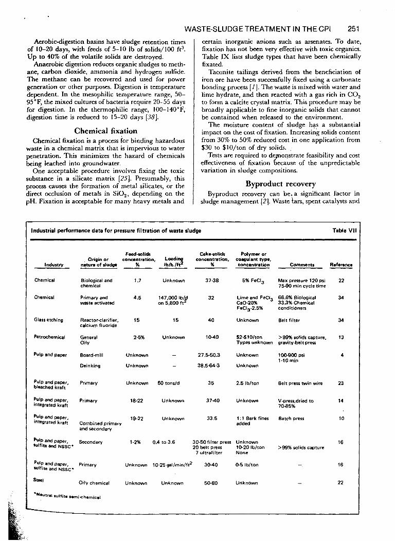
Table VI1 lists performance data for several indiis- trial pressure- fi 1 t ra tion operations.
Reverse osmosis and ultrafiltration l’he pressure-driven membrane processes-reverse
osmosis and ultrafiltration-- ti;i\.e found onl!, limited use in delvatering sludges because they cannot tolcratc large concentrations o f suspended niatcl-ial wiitiout srrious reduction i n flux. For example, ultrafiltration systcnir can concentrate solids t o on ly :3-.5‘;,’. Ho\vcvrr , these processes are useful when i t is ne( rate a r i d cwncentrate a colloidal o r d from a slurry. ‘Iiixic materials present in a liquid stream at \.cry low concentration (:an bt. concent solids in pressure-driven nicmihranc pro a n y s(:\’rre penalty other than ;in inc.re;t
‘trni prcssui~e, resulting from t l i r iric-rc;rsing o s i i i o t i c ,
p ~ ~ e s s ~ i i ~ c . Usual ly . 1 tit: niolccular w c a i q l i i of’ the spccirs t o
be scparatrd and concentrated is higti t b i i o i i , q t i t ha t [ t ic ,
prcssiii.~. iiicwasc. is insignificant. ‘l>h(* pro( tlrpriids on t h c . size of thc specics IO he conceiitratrd. For ionic hpecies, reverse-osrnosi\ is used, and for or-
ganic species ultrafiltration is used. ‘The concentrated liquid or viscous material can then be coincinerated with sludge.
Secondary sludge treatment Waste biological sludge is generated in the secondary
stages of waste treatment (Fig. 1) . Organic chemical, petrochemical and pulp and paper wastes usually re- quire biological treatment for I ~ I ) , biochemical oxygen demand, reduction in compliance with EPA’S BPTCA
(Rest Possible Technology Currently Available) stand- ards. This is accomplished in aerated lagoons, contact- media units and activated-sludge-treatment units. This discussion will consider only the latter.
‘I’he sludge product ion of act iva t ed-sludge processes is stio\zm i n Tat~le VIII. ‘I’he data are typical and are b a s d on freds consisting of less than 0.2 Ib inerts/lb k j o i ) . ‘l’he amount o f incrts i n the feed is critical. The sludgc prod-iccd has a concentration of 0.5% to 1.5%
m i n g is essential t o rcdricc. t h i s \,oIume prior to d e w - trring operations.
I f prirnary trratmcnt produc:es a sludge volume that is niucti ~ a r y c r t t i a n that I‘roln sm)ndary treatment, the sludges can be niixcti a n d dcwatrred together. How- ever, they arc. of’tvii kcpi scpra tc for better control 1x1
!I> :: src::n&ry c!2rifier. Thick-
WASTE-SLUDGE TREATMENT IN THE CPI 251 Aerobic-digestion basins have sludge retention times
of 10-20 days, with feeds of 5-10 Ib of solids/100 ft". Up to 40% of the volatile solids are destroyed.
Anaerobic digestion reduces organic sludges to meth- ane, carbon dioxide, ammonia and hydrogen sulfide. The methane can be recovered and used for power generation or other purposes. Digestion is temperature dependent. In the mesophilic temperature range, 50- 95"F, the mixed cultures of bacteria require 20-55 days for digestion. In the thermophilic range, 100-140°F, digestion time is reduced to 15-20 days [38].
Chemical fixation Chemical fixation is a process for binding hazardous
waste in a chemical matrix that is impervious to water penetration. This minimizes the hazard of chemicals being leached into groundwater.
One acceptable procedure involves fixing the toxic substance in a silicate matrix [25]. Presumably, this process causes the formation of metal silicates, or the direct occlusion of metals in SiO,, depending on the pH. Fixation is acceptable for many heavy metals and
certain inorganic anions such as arsenates. To date, fixation has not been very effective with toxic organics. Table IX lists sludge types that have been chemically fixated.
Taconite tailings derived from the beneficiation of iron ore have been successfully fixed using a carbonate bonding process [I]. The waste is mixed with water and lime hydrate, and then reacted with a gas rich in CO, to form a calcite crystal matrix. This procedure may be broadly applicable to fine inorganic solids that cannot be contained when released to the environment.
The moisture content of sludge has a substantial impact on the cost of fixation. Increasing solids content from 30% to 50% reduced cost in one application from $30 to $lO/ton of dry solids. ,
Tests are required to dewonstrate feasibility and cost effectiveness of fixation because of the unpredictable variation in sludge compositions.
Byproduct recovery Byproduct recovery can be, a significant factor in
sludge management [2]. Waste tars, spent catalysts and
Industrial performance data for pressure filtration of waste sludge Table VI1
Industry
Chemical
Chemical
Glass etching
Petrochemical
pulp and paper
pulp and paper, bleached kraft
pulp and paper, integrated kraft
Pulp and paper, integrated kraft
pulp and paper, sulfite and NSSC'
pulp and paper, wlfite and NSSC'
Snel
Origin or nature of sludge
Biological and chemical
Primary and waste activated
Reactorclarifier, calcium fluoride
General Oily
Board-mill
Deinking
Primary
Primary
Feedsolids concentration, Loading
% Ib/h /f$
1.7
4.5
15
24%
Unknown
Unknown
Unknown
18-22
19-22
Unknown
147,000 Ibld on 5,800 ft2
15
Unknown
- -
50 tonsld
Unknown
Unknown
Cake-solids concentration,
%
37-38
32
40
1040
27.5-50.3
38.564-3
35
3 7 4 0
33.5
Polymer or coagulant type, concentretion Comments Reference
5% Feci3 Max pressure 120 psi 75-90 min cycle time
Lime and Feci3 66.6% Biological ca0-20% 33.3% Chemical FeCI3-2.5% conditioners
Unknown Belt filter
$2$10lton >99% solids capture, Types unknown gravity-belt press
Unknown 100-900 psi
Unknown 1-10 min
2.5 lblton Belt press twin wire
Unknown Vpress.dried to 7085%
1 : 1 Bark fines added
Batch press
Secondary 1-2% 0.4 to 3.6 30-50 filter press Unknown 20 belt press 10-20 lblton >99% solids capture
7 ultrafilter None
Primary Unknown 10-25 gal/min/fG 3040 0-5 lblton -
oi ly chemical Unknown Unknown 50-80 Unknown -
*N*utr.l sulfite Semichemicnl
22
34
34
13
4
23
14
10
16
16
22
252 SOLID WASTE TREATMENT METHODS
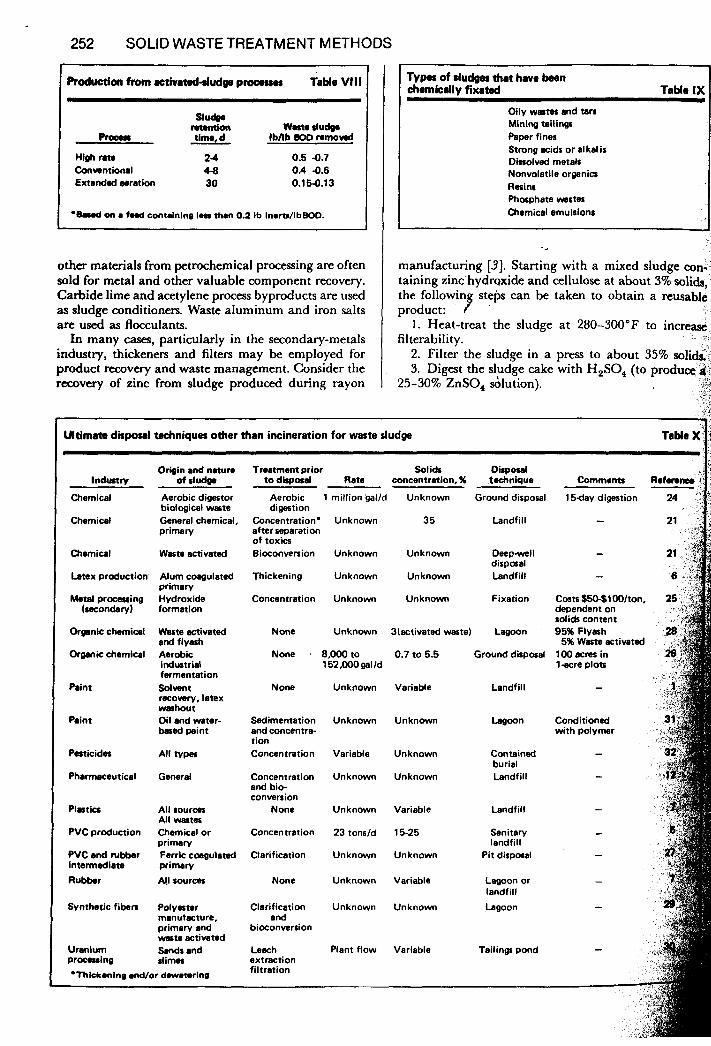
Roducdon from rctivateddudge procrrur Table Vlll
W.rt. dudg. mudo.
cumtion tima d lbhb BOD nmovad L PrOer
High m e 2 4 0.5 4.7 Conwntional 443 0.4 4.6 Extended oaration 30 0.154.13
.Bawd on a faad contdnlng 1 . a than 0.2 lb InortsAbBOD.
other materials from petrochemical processing are often sold for metal and other valuable component recovery. Carbide lime and acetylene process byproducts are used as sludge conditioners. Waste aluminum and iron salts are used as flocculants.
In many cases, particularly in the secondary-metals industry, thickeners and filters may be employed for product recovery and waste management. Consider the recovery of zinc from sludge produced during rayon
TYPOS of sludges that have been chemically fixated TaMe IX
Oily wastes and tars Mining tailings Paper fines Strong acids or alkalis Dissolved metals Nonvolatile organics Resins Phosphate wBstes Chamicsl emulsions
manufacturing [3]. Starting with a mixed sludge con taining zinc hydrsxide and cellulose at about 3% soli& the followin steps can be taken to obtain a reusablc
1. Heat-treat the sludge at 280-300°F to i n c w
2. Filter the sludge in a press to about 35% solids 3. Digest the sludge cake with H,SO, (to produce 8
product: 7 ' filterability.
25-30% ZnSO, dlution).
Ultimate disposal techniques other than incineration for waste sludge Table X'
lndustrv
Chemical
Chemical
Chemical
Latex production
Metal processing (racondaryl
Organic chemical
O-nic chemical
Paint
Paint
Pasticides
Pharmaceutical
Plastics
PVC production
PVC and rubbar intermadiate Rubber
Synthetic fibers
Uranium procming
Origin and natura of rludm
Aerobic digestor biological waste General chemical, primary
Waste activated
Alum coagulated primary Hydroxide format ion
Waste activatad and flyash Aerobic industrial fermentation Sdwnt racowry, latex washout Oil and water- based paint
General
All sources Mi wastes Chemical or primary Ferric cmgulsted primary All sources
Polyester manutacture, primary and waste activated Sands and slimes
*Thkkanlng and/or dwamrlng
Traatmant prior Solids Disposal to disposal Rata concentration, % tachnique Comments
Aerobic 1 million galld Unknown Ground disposal 15day digestion digestion
Concentration' Unknown 35 Landfill - after separation of tox-m Bioconversion Unknown Unknown Deep-well
dispaal Thickening Unknown Unknown Landfill
Concentration Unknown Unknown Fixation Costs $50-$1001ton, dependent on solids content
None Unknown Bbctivated waste) Lagoon 95% Flyash
None 8,000to 0.7 to 5.5 Ground disposal 100 acres in 1 a r e plots
5% Waste activatad
1 52,000 gal /d
Conditioned with polymer
None Unknown Variable
Sedimentation Unknown Unknown and concentra- t ion Concentration Variable Unknown
Concentration Unknown Unknown and bio- conversion
None Unknown Variable
Concentration 23 tonsld 15-25
Clarification Unknown Unknown
None Unknown Variable
Clarification Unknown Unknown and
bioconversion
Leach Plant flow Variable extraction filtration
Landfill
Contained burial Landfill
Landfill
Sanitary landfill
Pit disposal
Lagoon or landfill Lagoon
Tail ing pond
WASTE-SLUDGETREATMENT IN THECPI 253
4. Refilter the sludge in a filter ptts (to remove
5. Oxidize ferrous iron with H,O,; adjust pH to 4.5. 6. Remove ferric iron on a rotary precoat filter. This is only one example of the many waste-recovery
processes that are now or will soon be in use. With the cost of disposal on the rise, recovery and reuse is a
potential profit area and an engineering and process
Disposal Though methods of sludge disposal are beyond the
scope of this article, Table X lists examples of industrial disposal techniques other than incineration.
CaSO, and organics). design challenge.
References , I Carbonate Bonding of Taconite Tailings, USEPA. Office of Racarch and
Development, EPA-670/2-74-001, Jan, 1974 2 Bud , R S , A Study of Sludge Handling and Disposal, U S Dept of the
Intenor, Federal Water Pollution Control Administration, Office of Re- search and Development, WP-20-4, May, 1968
3 lammartino, N R , Wastewater Clean-up Procsses Tackle Inorganic Pollutants, Chrm Eng, Sept 13, 1976, p I18
4 State-of-the-Art Review of Pulp and Paper Waste Treatment, USEPA, Office of Research and Momtoring, EPA-R2-73-184, 1973
5 Wastewater Treatment Facilities for Polyvinyl Chloride Production Plant, USEPA, Water Pollution Control Research Series, 12020 DJI, June, 1971
6 Putting the Closed Loop into Practice, Emiron Sci Tcchnol, Vol 6, No 13, Dec 1972, p 1,072
7 Fluidized-Bed Incineration of Selected Carbonaceous Industrial Wastes, USEPA, Water Polluuon Control Research Series, 12120 FYF, March 1972
8 Air Flotation-Biological Oxidation of Synthetic Rubber and Latex Wastewater, USEPA, Environmental Protection Technology Series, EPA- 660/2-73-018, Nov , 1973
9 Environmental Considerations and the Modern Electrolytic Zinc Refinery, MIR Eng, Vol 29, No 11, Nov 1977, p 31
Mulligan, T J , South, W D , and DJO~JCVIC, B , Thickening and L a t e r i n g Characteristics of Kraft Mill Sludges From a High-Purity Oxygen Treatment System, Tuppi, Vol 57, 1974, p 119
I I Wills, J r , Robert H , Crucible Waste Treatment, Clear Walcrs, J of N Y WPCA, Vol 6, No 4, Dec 1976, p 15
I 2 Interim Final Effluent Guidelines for The Pharmanutical Manufacturing Industry, USEPA, 440/1-75/060 Group 11, 1976
13 Grove, George W , Use Gravity Belt Filtration for Sludge Disposal, API Special Report,Hy&ocarh Rocess, May 1975, p 82
14 Methods of Pulp and Pa r Mill Slud e Utilization and Disposal, USEPA, Office of Research and Gonitonng, [PA-R2-73-232, 1973
I5 Bishop, Fred W , and Drew, A E , Disposa: of Hydrous Sludges From a Paper Mill, Tappi, Vol 60, No 11, Nov 1971, p 1830
16 Miner, R A , Marshall, D W , and Gellman, I L , A Pilot Investigation of Secondary Sludge Dewatering Altcmatives, National Council of the Pa Industry for Air and Stream Improvements Inc , USEPA, EPA-6OOI2-E 014, Feb , 1978
17. Turkki, E V , Hildebrand, A S , and Nemerow, N L , Removal of Fine Solids from Chemical Waste Stream Through P-t Rotary Vacuum Filtration, Roc, 30th Pudue, Ind , Waste Conf, 1977, p 122
18 Limestone Treatment of k n s c Waters from Hydrochlonc Acid Pickling of stel, USEPA, Water Quality Office, 12010 DUL, Feb 1971
19 Sludge Material Recovery Syatcm for Manufacturers of Pi mcntcd P a p , USEPA, Waste Pollution Control Resea& Senes, 12040%ES, July 1971
20 Color Removal from Kraft Pulp Mill Effluents by Massive Lime Treat- ment. USEPA, Office of Research and Monitoring, EPA-R2-73-086. Feb 1973
21 b e t t , J W , How Dow Chemical Deals with Diverse Wasta, C h n fiwcss, VOl 31, No 1, Jan 1968, p 20
22 Kellogg, Stephen R , and Weston, Roy F , Tnatment of Various Industrial S i u d P by Pn~sure Filtration, The Eleventh Mid-Atlantic Regional Meting of ACS, Univelsity of Delaware, E-6158, April 1977. *’ p M , and Metzger, L R , Startup and Operating Ex nence with aTwln-Wire Moving Belt-Pms for Pnmary Sludge, Tappi, & 60, No 9, S P t 1977, p 120
A , and Walls, W V , Upgrading of Industrial WPstwaterTmtment Facilities at Tennessee Eastman Co , 1977 Water & Wastewater Equipment Mfls Assn Industnal Conference, Atlanta, Ca , 1977
10 Kehrberger, G
’‘ Howard*.! ’8, Pdusica,
30. State-of-the-Art Uranium Mining, Milling; and Refining Industry, USEPA, Office of Raearch and Development, EPA-670/2-74-030, March 1974.
31. Waterborne Wastes of the Paint and Inorganic Pigments Industries, USEPA, Office of Research and ,he lopmen t , EPA-670/2-74-030, March, 1974.
32. The Pesticide Manufacturing Indust+Current Waste Treatment and Disposal Practices, USEPA, W ter Pollution Control Research Series,
33. “Ultimate Disposal of Liquid Wastes by Chemical Fixation,” Chem Fix Div., Environmental Sciences Inc., 1977.
34. Data from Envirotcch Corp., Eimco Machincry Prwlucts Div., Salt Lake City, Utah.
35. Vesiland, P. A., “Treatment and Disposal of Wastewater Sludges,” Ann Arbor Science, Mich., 1974. *
36. Perry, R. H., et al.. “Chemical Engine& Handbook,” 5th cd., M d r a w - Hill, New York, 1973, p. 19-60.
37. Nelson, P. A,, and Dahlstrom, D. A,, Moisture Content Comlation of Rotary Vacuum Filter Cake, Chcm. Ens. Progress, Vol. 53, No. 7, July 1957, p. 320.
38. “Waste Water Treatment Plant h i n ” Manual of Practice No. 8, WPCF and ASCE, Lancaster Press, Pa., 19’5;.
->
12020 FYE, Jan. 1972. f
The authors
OKEY KOMINEK DICRECORIO
Robert Okey is Director of Technical S w i m s for Envirotcch Corp., Eimco Procxss Machinery Div., 669 West Second South, P.O. Box 300, Salt Lake City, UT 841 IO. (801) 521-2000. Previously, he was the water-and-waste staff technologist for an engineering and construction firm, a consultant, and Eastern Washington State District Engineer. He has taught at Seattle University and the University of Southern California. He has a B.S. in Agricultural Engineering from Iowa State Coll and a B.S. in Civil Engineering and M.S. in Sanitary Enginceringeff” the Univmity of Washington, Seattle. Mr. Okey has a u t h o d many articles on wastewater treatment and mntribiiied 10 the Water Pollution Contml Federation Manuals of Practice. He is a member of WPCF, AIChE and ASCE, and is a registered Profcasional Engineer in eleven states.
Edward G. Kominek is the Manager of Carbon System Operations for * Envimtech C o p . , Eimco Pmccss Machinery Div. During his 35 years in waicr- and waste-treatment activities, his major experience has been in
rocess design and research and development. He has rracived B.S. and L.B.A. degrees from the University of Chicago and is a registered professional engineer in Ohio, Illinois and Arizona. Mr. Kominek has authored several pa AIChE, WPCF, A&A, API and others.
David DiCregorio is Director of Sanitary Engineering Research and Development for Envirotech Corp., Eimco Process Machinery Div. His responsibilities include the development and application of unit processes for wastewater trratment. Before Joining Eimco in 1971, he worked in rcscarch and development at Dorr-Oliver. Mr. DiCregorio has a B.S. in Civil Engineering fmm the University of Massachusetts and an M.S. from Cornell University, Ithaca, New York. He has authored papers on waste treatment and solids processing, worked on two EPA-sponsored research contract studies and contributed to the WPCF Manuals of Practin. H e is a member of<WPCF and a registered Profeslional Engineer in Utah.
n on water and waste trcatment. H e is a member of
INDUSTRIAL WASTEWATER AND SOLID WASTE ENGINEERING
Edited by
Vincent Cavaseno and the Staff of Chemical Engineering
McCraw-Hill Publications Co., New York, N.Y.
Copyright01980 by Chemical Engineering McGraw-Hi11 Pub. Co. 1221 Avenue of the Americas, New York, New York 10020
All rights resewed. No parts of this work may be reproduced or utilized in any form or by any means, electronic or mechanical, including photocopying, microfilm and recording, or by any infor- mation storage and retrieval system without permission in writing from the publisher.
Printed in the United States of America
Library of Congress Cataloging in Publication Data
Main entry under title:
Industrial wastewater and solid waste engineering.
1. Factory and trade waste. 1. Chemical engineering. TD897.1435 638.5’4 80-12608 ISBN 0-07-6066630 (paper)
0-074106944 (case)