Embed Size (px)
Citation preview
WM’00 Conference, February 27-March 2, 2000, Tucson, AZ
WASTE REMOVAL FROM THE WEST VALLEY DEMONSTRATION PROJECT HIGH-LEVEL RADIOACTIVE WASTE STORAGE TANKS
William F. Hamel, Jr., U.S. Department of Energy - West Valley Demonstration Project
Carol L. McMahon, West Valley Nuclear Services Co. - West Valley Demonstration Project Daniel C. Meess, West Valley Nuclear Services Co. - West Valley Demonstration Project
ABSTRACT The West Valley Demonstration Project (WVDP) has mobilized, removed, and vitrified approximately 96 percent of the high-level radioactive waste (HLW) from its three HLW storage tanks. During the first three years of waste processing, waste removal was performed solely by mobilizing the slurry within the tanks and pumping the waste stream to the Vitrification Facility. As removal of the remaining small quantity of waste becomes increasingly more difficult, new, advanced waste retrieval and heel characterization equipment has been developed. The first systems have been deployed within the HLW tanks to better determine the amount of waste remaining and provide alternative waste mobilization and removal methods. This paper will discuss the WVDP experience in waste removal using mobilization pumps, highlight the new, advanced equipment installed in the HLW tanks in 1999, and describe advanced waste removal/characterization equipment currently being developed for future deployment. The combination of the existing and advanced waste mobilization, removal, and characterization systems are expected to remove greater than 99 percent of the original HLW activity and will quantify the remaining residual activity. INTRODUCTION The WVDP is located about 30 miles south of Buffalo, New York, on the site of a former commercial spent fuel reprocessing facility which operated from 1966 to 1972. Approximately 640 metric tons of commercial and defense fuels were reprocessed at the site using the plutonium-uranium extraction (PUREX) and the thorium extraction (THOREX) processes. The former site operator, Nuclear Fuel Services (NFS), Inc., halted reprocessing operations in 1972 to evaluate the potential for facility expansion. In 1976, NFS notified New York State that it would withdraw from operating the facility in 1980, when their lease expired. In 1980, the West Valley Demonstration Project (WVDP) Act was signed, directing the U.S. Department of Energy (USDOE) to: solidify and develop suitable containers for the site’s high-level radioactive waste; transport the solidified waste to a federal repository; and dispose of the low-level radioactive and transuranic wastes created during reprocessing operations. In 1982, the USDOE took control of the site working closely with the New York State Energy Research and Development Authority (NYSERDA). A private company, West Valley Nuclear Services Co., was awarded the operations contract and has been the primary contractor since February 1982. New York State owns both the site and the waste. Under the WVDP Act, the USDOE is responsible for management of the Project and funds 90 percent of the cleanup costs while working with NYSERDA, who funds the remaining 10 percent. Approximately 2.0 million L of neutralized high-level PUREX radioactive waste remained on the site in an underground carbon steel storage tank designated as 8D-2. This waste consisted of insoluble hydroxides and other salts that precipitated out of the solution to form a bottom sludge layer, and a liquid top layer rich in sodium nitrate and nitrite (supernatant). In addition, approximately 31,000 L of acidic THOREX waste remained in an underground stainless steel storage tank designated 8D-4 (1). WASTE PRETREATMENT AND CONSOLIDATION Waste is being solidified into glass via vitrification in two stages. In the first stage, called pretreatment, the chemical compounds that have a detrimental effect on the final vitrified HLW form, such as sodium sulfate, are separated from most of the radioactive elements and solidified into cement. Without pretreatment of the HLW, the quantity of vitrified waste would increase over tenfold from the current estimated projection of 300 glass-filled canisters. In the second stage, the remaining waste (mostly solids from tank sludge and zeolite ion-exchange media) is mobilized by mixing pumps and transferred to the Vitrification Facility for solidification into glass logs. Figure 1 illustrates the various waste pretreatment processes and the subsequent vitrification.
WM’00 Conference, February 27-March 2, 2000, Tucson, AZ
Fig 1. HLW Pretreatment and Subsequent Vitrification Processes

WM’00 Conference, February 27-March 2, 2000, Tucson, AZ
Pretreatment, or the first stage of solidification of the HLW, began in 1988 (2). The supernatant was processed using ion-exchange columns containing zeolite located inside spare HLW Tank 8D-1 that removed greater than 99.9 percent of the radioactive materials (mostly cesium-137). The resultant effluent salt solution was concentrated, blended with cement, and stored as low-level waste (LLW) in a shielded, aboveground, on-site facility. Supernatant processing was completed in 1990 producing a total of 10,393 270-L drums. Mobilization pumps were then installed into the HLW tank to mix and wash the sludge portion of the waste. This washing process included the addition of process water to the tank to dissolve additional interstitial sulfates. Salt/sulfate removal was necessary to reduce the amount of these compounds processed into glass and the resulting quantity of canisters produced during the vitrification campaign. The wash water was then processed similarly to the supernatant; however, titanium-coated zeolite was used as the filter material in the ion-exchange columns. The titanium-coated zeolite adequately captured cesium-137 but was significant in that it also captured plutonium and strontium that had solubilized during the washing process. Two sequential PUREX sludge washes were performed. Sludge washing created 2.9 million L of liquid that was processed as supernatant liquids, then evaporated, mixed with cement, and placed in 8,033 270-L steel drums. During 1995, the acidic THOREX waste (85,000 kg or 94 tons, 40 percent water and 50 percent nitrates of thorium, iron, and aluminum) in Tank 8D-4, leftover from past fuel reprocessing, was combined with the waste in Tank 8D-2 and chemically neutralized. The resulting THOREX sludges and the PUREX sludge were then washed and processed. The net effect of the wash was an additional 1.2 million L of liquid waste solidified into 1,451 drums. The processing of liquid from washing the PUREX-based sludge and the additional THOREX waste was completed in 1995, resulting in a total of 6.4 million L of liquid being processed and a total of 19,877 drums of cement-based waste produced and stored on site. Nearly all of these drums meet the Nuclear Regulatory Commission (NRC) criteria for Class A, B, or C low-level radioactive waste. The spent zeolite from the ion-exchange process in Tank 8D-1 was then transferred to Tank 8D-2. The zeolite particles were size-reduced with an in-line grinder during transfer operations. The remaining zeolite and sludge mixture is the feed for the vitrification process providing 17 percent of the glass chemical composition. The waste consists of insoluble metal hydroxides, with ferric hydroxide being the major constituent. The sludge mass was estimated at 100,000 kg with a specific gravity (SG) of 3.35. Based on sludge sampling and analysis, the particle size of the sludge was generally less than 100 microns. The predominant radionuclides in the sludge are strontium-90 and isotopes of thorium and uranium. The activity of the strontium-90 was estimated to be approximately 5.2 million curies in January 1996. An estimated 6.6 million curies of cesium-137, nearly all contained within the zeolite, are in the waste mixture. HLW MOBILIZATION AND TRANSFER Underground waste storage tanks 8D-1 and 8D-2 are identical 2.8 million L, carbon steel storage tanks contained within a concrete vault and in a secondary containment pan. The primary waste tank is Tank 8D-2 (see Figure 2). Each tank is 21 m in diameter and 8.2 m high with wall thicknesses ranging from 11 mm to 17 mm. These tanks have a complex internal gridwork structure providing reinforcement and support to the tanks as well as to the columns that support the vault roof. The tanks’ internal gridwork is comprised of a network of wide flange beams supported underneath by vertical plates of varying lengths and widths. These girders attach to the tank bottom by rods held on with reinforcing disks. Forty-five pipes columns (in each tank) connect the beams to the tank top and provide support to the roof. Various air circulators, thermowells, and level/density probes also reside within the tanks. Waste mobilization and removal efforts have been uniquely challenging due to the tanks’ internal configuration and in part to the internal structures. These structures act to disperse the mobilization pumps’ mixing jets which result in nonuniform cleaning/mixing radii and “dead zones” where the low local velocity causes the solids to fall out of suspension and deposit on tank surfaces. These effects are minimized by the periodical indexing of the mobilization pumps’ jets at these areas for a longer duration to remobilize the deposited solids.

WM’00 Conference, February 27-March 2, 2000, Tucson, AZ
Fig. 2. Plan View of HLW Tank 8D-2
Six long-shafted centrifugal mobilization pumps are installed in Tank 8D-2 to mix the solids that settled on the tank bottom with the liquid supernatant. Five mobilization pumps were installed for sludge washing operations and a sixth pump was added in the M4 riser in 1998 to compensate for an inoperable pump in the M5 riser. Eventual replacement of the failed pump posed a challenge due to its being submerged under high-activity HLW solids and its long length. These pumps are each 15.3 m in length with a single impeller to draw the slurry up into the pump suction and a strainer device to keep out larger debris. The suction is positioned from 2.5 cm to 4.0 cm from the tank bottom with discharge jets approximately 18 cm above the tank bottom. Two tangential nozzles are used to discharge liquid from the volute above the suction. Mechanical seals on the pump column top and bottom maintain a pressurized water column to cool and lubricate the nine driveline bearings. Each pump is driven by a 150-hp motor controlled by an individual variable frequency drive (VFD) for speed adjustment. The pumps are mounted onto bearing assemblies that enable them to fully rotate in either direction permitting the two fixed discharge nozzles to sweep the tank bottom within a 4 to 10 m radius around each pump and to mobilize the accumulated solids. The rotational speed of the pump nozzles is also controlled by a VFD. Additionally, one long-shafted vertical turbine transfer pump was installed in Tank 8D-2. This pump is approximately 12 m long with a radial inlet suction and two concentric strainers about 3 to 4 cm above the tank bottom. The pump is driven by a 20-hp motor with a VFD for flow control and is located in a remote shielded pump pit. The pump is additionally equipped with instrumentation to allow remote operation and performance monitoring and with vibration sensors to monitor pump wear. The transfer pump is located in an underground concrete pump pit above the HLW tank. This pit houses the pump head, discharge piping, motor, and primary and spare transfer lines to spare HLW Tank 8D-1 and the Vitrification Facility. A recirculation line is also provided. Remotely replaceable valved jumpers are used to connect the piping and for the placement of monitoring equipment. An in-line grinder used during pretreatment to size-reduce the zeolite and its motor and cooling water lines are also housed within the pit. Access to the pit is by six keyed concrete covers. Adjacent to the pump pit is a utility pit with valving for isolation control and backflow protection of water and air supply systems. A 70 m long seismically designed concrete transfer trench connects the pits to the

WM’00 Conference, February 27-March 2, 2000, Tucson, AZ
Vitrification Facility. Like the pump pit, the trench has removable concrete covers to provide access. Transfer piping within the trench is 6 cm diameter stainless steel inside an 11 cm diameter stainless steel secondary containment. The trench is equipped with leak detectors, radiation probe penetrations, high-point vents, and exterior valving for monitoring and safety control functions. Figure 3 illustrates the physical locations of the HLW tanks, pump pits, transfer trench, and Vitrification Facility.
Fig. 3. Waste Tank Farm Facilities Supporting Vitrification
The originally installed transfer pump failed on January 27, 1998, after 53 HLW transfers to the Vitrification Facility. Based on its operating characteristics prior to complete inoperability, the cause is attributed to either severe bearing wear in the region of the 13-stage impeller section or damage to one of its impellers. Another of the major operational challenges was the replacement of this highly contaminated pump with an improved spare in record time: resuming operations on March 30, 1998 (3). HLW MOBILIZATION AND WASTE REMOVAL From June 1996 through September 1998, over 102 transfers of waste from Tank 8D-2 to the Vitrification Facility have been performed. These transfers made up 58 batches of feed for the melter containing 10.3 million curies of cesium-137 and strontium-90, and comprised approximately 88 percent of the initial HLW tank inventory. The tank level during this time frame was approximately 2.5 m and was subsequently reduced during the later transfers to about 25 cm. Other liquids from laboratory analysis of samples, distillates from waste concentration in the Vitrification Facility, and clean water used to lubricate and cool the mobilization pump driveline bearings were added to the tank during this period. It is estimated that 1.3 million L of clean water was added to the tank due to mobilization pump column leakage. Volume reduction of some of the excess liquid was performed in the Integrated Radwaste Treatment System (IRTS). Some portion of the liquid was decanted back to the spare 8D-1 tank. Both operations were critical to maintaining the HLW concentration in the primary waste tank supplying the Vitrification Facility. From October 1, 1998, to December 31, 1999, 24 transfers of waste from Tank 8D-2 to the Vitrification Facility have been performed. These transfers made up 3 feed batches and contained approximately 460,000 curies of cesium-137 and 160,000 curies of strontium-90 for a total of 620,000 curies. These numbers, compared to prior years, indicate that waste removal is being accomplished at a much slower rate as waste removal becomes more tedious.
WM’00 Conference, February 27-March 2, 2000, Tucson, AZ
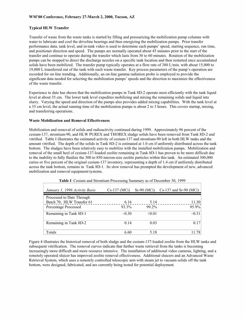
Typical HLW Transfer Transfer of waste from the waste tanks is started by filling and pressurizing the mobilization pump columns with water to lubricate and cool the driveline bearings and then energizing the mobilization pumps. Prior transfer performance data, tank level, and in-tank video is used to determine each pumps’ speed, starting sequence, run time, and positioner direction and speed. The pumps are normally operated about 45 minutes prior to the start of the transfer and continue to operate during the transfer which lasts from 30 to 60 minutes. Rotation of the mobilization pumps can be stopped to direct the discharge nozzles on a specific tank location and then restarted once accumulated solids have been mobilized. The transfer pump typically operates at a flow rate of 380 L/min. with about 15,000 to 19,000 L transferred out of the tank with each waste transfer. Key process parameters of the pump’s operation are recorded for on-line trending. Additionally, an on-line gamma radiation probe is employed to provide the significant data needed for selecting the mobilization pumps’ speeds and the direction to maximize the effectiveness of the waste transfer. Experience to date has shown that the mobilization pumps in Tank 8D-2 operate most efficiently with the tank liquid level at about 35 cm. The lower tank level expedites mobilizing and mixing the remaining solids and liquid into slurry. Varying the speed and direction of the pumps also provides added mixing capabilities. With the tank level at a 35 cm level, the actual running time of the mobilization pumps is about 2 to 3 hours. This covers startup, mixing, and transferring operations. Waste Mobilization and Removal Effectiveness Mobilization and removal of solids and radioactivity continued during 1999. Approximately 96 percent of the cesium-137, strontium-90, and HLW PUREX and THOREX sludge solids have been removed from Tank 8D-2 and vitrified. Table I illustrates the estimated activity of cesium-137 and strontium-90 left in both HLW tanks and the amount vitrified. The depth of the solids in Tank 8D-2 is estimated at 1.0 cm if uniformly distributed across the tank bottom. The sludges have been relatively easy to mobilize with the installed mobilization pumps. Mobilization and removal of the small heel of cesium-137-loaded zeolite remaining in Tank 8D-1 has proven to be more difficult due to the inability to fully fluidize the 300 to 850 micron-size zeolite particles within this tank. An estimated 300,000 curies or five percent of the original cesium-137 inventory, representing a depth of 1.4 cm if uniformly distributed across the tank bottom, remains in Tank 8D-1. Its slow removal has prompted the development of new, advanced mobilization and removal equipment/systems.
Table I Cesium and Strontium Processing Summary as of December 30, 1999 January 1, 1996 Activity Basis
Cs-137 (MCi)
Sr-90 (MCi)
Cs-137 and Sr-90 (MCi)
Processed to Date Through Batch 70, HLW Transfer 61 6.16 5.14 11.30 Percentage Processed 93.3% 99.2% 95.9% Remaining in Tank 8D-1 ~0.30 <0.01 ~0.31
Remaining in Tank 8D-2 0.14 0.03 0.17
Totals 6.60 5.18 11.78 Figure 4 illustrates the historical removal of both sludge and the cesium-137-loaded zeolite from the HLW tanks and subsequent vitrification. The removal curves indicate that further waste retrieval from the tanks is becoming increasingly more difficult and more resource intensive. The installation of additional video cameras, lighting, and a remotely operated sluicer has improved zeolite removal effectiveness. Additional sluicers and an Advanced Waste Retrieval System, which uses a remotely controlled telescopic arm with steam jet to vacuum solids off the tank bottom, were designed, fabricated, and are currently being tested for potential deployment.

WM’00 Conference, February 27-March 2, 2000, Tucson, AZ
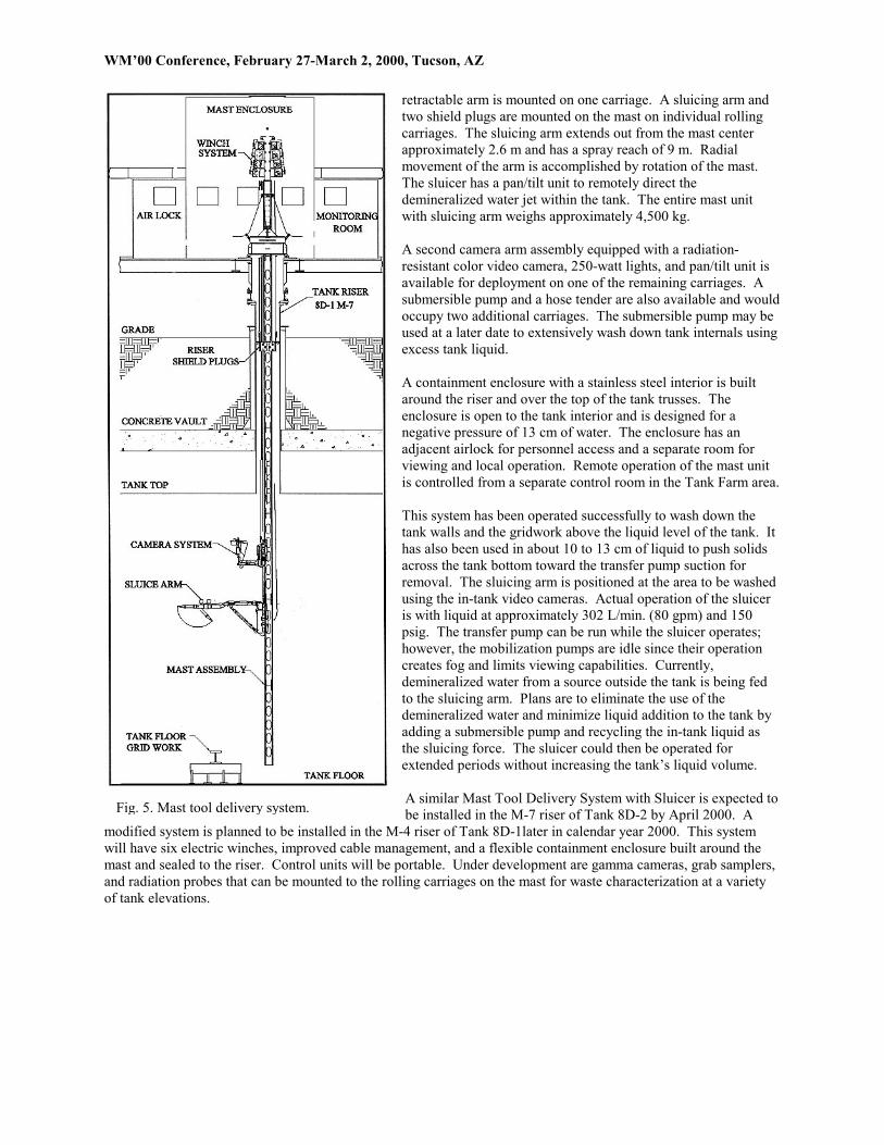
Fig. 4. HLW Mobilization and Removal Progress Removal of sludge and size-reduced zeolite from Tank 8D-2 will continue through most of fiscal year 2000 with the goal of achieving greater than 99.9 percent removal of the original PUREX and THOREX sludge activity by September 2000. The small amount of remaining activity will be evaluated for stabilization with a special grout mixture that would result in the tank and its contents meeting the NRC’s 10 CFR 61 limits for Class C low-level radioactive waste. Once Tank 8D-2 is cleaned sufficiently, additional cesium-137-laden zeolite from Tank 8D-1 will be mobilized and transferred to the Vitrification Facility. The zeolite transferred will be combined with other glass-formers to flush HLW from the process vessels and melter. This effort will begin in fiscal year 2000 and is scheduled to finish by mid fiscal year 2001. SYSTEM IMPROVEMENTS Two video cameras installed in the risers of Tank 8D-1 showed various areas of accumulated solids. These solids were not easily mobilized with standard mobilization pump operation. Additionally, all areas of the tank could not be seen due to the illumination limitation of the existing camera/light units and the internal obstructions such as pipe columns and the bottom gridwork. Improved methods of in-tank viewing, waste mobilization, and removal techniques were needed to locate accumulated solids on and under tank internals and to mobilize these solids into areas where removal would be possible. Mast Tool Delivery Systems In March 1999, a Mast Tool Delivery System with Sluicer was installed in the M-7 riser of Tank 8D-1 (see Figure 5). This system is comprised of a fabricated 15 m long stainless steel beam inserted into the riser. The beam extends to within approximately 30 cm from the bottom of the tank. The top of the beam extends out of the riser and is mounted to a rotary bearing (similar in movement to a turntable) connected to an electric gear motor. Mounted to the mast, above the rotary bearing, is a series of eight hydraulic winches and actuators in a winch stand assembly. These winches raise or lower carriages down both sides of the vertical mast. The carriages serve as platforms to lower tooling or cameras down inside the tank. Standard hydraulic fluid is used in the hoses outside of the tank and water is used as the hydraulic fluid inside the tank to mitigate the potential for adding any organic-containing fluid to the tank. Each winch has a lifting capacity of 454 kg (1,000 lb). A radiation-resistant, black-and-white video camera equipped with four 250-watt flood/spot variable intensity lights and a pan/tilt unit on a
WM’00 Conference, February 27-March 2, 2000, Tucson, AZ
retractable arm is mounted on one carriage. A sluicing arm and two shield plugs are mounted on the mast on individual rolling carriages. The sluicing arm extends out from the mast center approximately 2.6 m and has a spray reach of 9 m. Radial movement of the arm is accomplished by rotation of the mast. The sluicer has a pan/tilt unit to remotely direct the demineralized water jet within the tank. The entire mast unit with sluicing arm weighs approximately 4,500 kg. A second camera arm assembly equipped with a radiation-resistant color video camera, 250-watt lights, and pan/tilt unit is available for deployment on one of the remaining carriages. A submersible pump and a hose tender are also available and would occupy two additional carriages. The submersible pump may be used at a later date to extensively wash down tank internals using excess tank liquid. A containment enclosure with a stainless steel interior is built around the riser and over the top of the tank trusses. The enclosure is open to the tank interior and is designed for a negative pressure of 13 cm of water. The enclosure has an adjacent airlock for personnel access and a separate room for viewing and local operation. Remote operation of the mast unit is controlled from a separate control room in the Tank Farm area. This system has been operated successfully to wash down the tank walls and the gridwork above the liquid level of the tank. It has also been used in about 10 to 13 cm of liquid to push solids across the tank bottom toward the transfer pump suction for removal. The sluicing arm is positioned at the area to be washed using the in-tank video cameras. Actual operation of the sluicer is with liquid at approximately 302 L/min. (80 gpm) and 150 psig. The transfer pump can be run while the sluicer operates; however, the mobilization pumps are idle since their operation creates fog and limits viewing capabilities. Currently, demineralized water from a source outside the tank is being fed to the sluicing arm. Plans are to eliminate the use of the demineralized water and minimize liquid addition to the tank by adding a submersible pump and recycling the in-tank liquid as the sluicing force. The sluicer could then be operated for extended periods without increasing the tank’s liquid volume. A similar Mast Tool Delivery System with Sluicer is expected to be installed in the M-7 riser of Tank 8D-2 by April 2000. A
modified system is planned to be installed in the M-4 riser of Tank 8D-1later in calendar year 2000. This system will have six electric winches, improved cable management, and a flexible containment enclosure built around the mast and sealed to the riser. Control units will be portable. Under development are gamma cameras, grab samplers, and radiation probes that can be mounted to the rolling carriages on the mast for waste characterization at a variety of tank elevations.
Fig. 5. Mast tool delivery system.

WM’00 Conference, February 27-March 2, 2000, Tucson, AZ
Dual Arm Camera System In July 1999, a Dual Arm Camera System was installed in the N-12 riser of Tank 8D-1 to provide a third video camera in the center of the tank for enhanced tank residual waste mapping (see Figure 6). This system is comprised of a 9 m long rotating mast with electric motor that is inserted into the riser. Two extendable arms are attached to the mast and are folded flat to the mast to permit the unit to be installed and lowered into the 30 cm diameter riser opening. The lower arm has one radiation-hardened camera and two 250-watt spotlights on a pan/tilt mechanism. The camera is cabled to a controller that is in-line with a monitor and VCR. The upper arm has three 250-watt spotlights on a pan/tilt mechanism. The pan/tilt mechanism and the lights are operated by a separate controller. A linear actuator extends the arms outward approximately 2.0 m from the mast’s center to be able to view around tank obstructions. The Dual Arm Camera System has been used to view the tank’s condition and to map the solids accumulated on the bottom of the tank. The added interior illumination has revealed additional areas of solids to be mobilized. The pan/tilt design of the camera units on the extension arms has allowed positioning of the cameras to “see” around the pipe columns to identify previously hidden tank locations. An additional Dual Arm Camera System is also available for use in Tank 8D -2.
Mobilization Pump Protection Controls To maximize waste removal from Tank 8D-2, the liquid level is maintained at a depth of approximately 25 to 35 cm. This level is about the minimum needed to safely operate the mobilization pumps without cavitation that results from drawing air into the pump suction. Mobilization pump protection controls were designed and installed on all 11 mobilization pumps to minimize the potential for pump damage. The horsepower of each operating mobilization pump is continuously monitored to ensure that severe cavitation or pump suction plugging does not occur. In addition, an automatic shutdown system safely monitors the horsepower of each pump and shuts off the pumps if the actual horsepower drops below preset adjustable limits, as happens when the pumps begin to draw air into their suctions or when large tank solids plug the pump suction strainers. Built-in timers also allow automatic mobilization pump restarts under certain conditions. This system has proven extremely valuable to protect the large mobilization pump investment. MAJOR CHALLENGES As the WVDP begins its fourth year of HLW removal and vitrification, there are still many challenges to be faced. These challenges result from the goal to remove 99.9 percent of the long-lived radionuclides. The most difficult challenge is determining what remains in the 8D-1 and 8D-2 tank waste heels. The waste being removed from the tanks is sampled and extensively analyzed in the vitrification process, and this data is being used to characterize the composition of the waste remaining in the tanks. However, this method assumes that all of the zeolite and sludge remaining in the tanks is being homogeneously mixed by the mobilization pumps. It also assumes that there is minimal waste firmly fixed to the tanks’ surfaces or absorbed within the tanks’ surfaces. Both of these statements
Fig. 6. Dual arm camera system.

WM’00 Conference, February 27-March 2, 2000, Tucson, AZ
must be verified within a tolerance band that supports closure criteria. Sampling the tanks’ contents would be the normal response to resolving the quantity and types of radionuclides remaining, but this task is quite formidable. The prospect of sampling loose solids from the tank bottom, scrape sampling the horizontal and vertical surfaces, and core drilling certain nonstructural tank internals poses considerable resource demands and potentially involves significant radiation doses. The WVDP is developing sampling systems to verify that tank cleanliness requirements are being met, but in the interim is planning the use of simpler characterization techniques that may reduce the size of the future sampling program and save both cost and personnel dose. These types of techniques include visual inspection, radiation sensors, radiation/gamma cameras, and rare gas sampling, in addition to the continued sampling of the vitrification tank to which this waste is transferred. Visual techniques have been employed within both waste tanks and have identified regions within the tanks that require additional waste mobilization. Although the WVDP has been successful in identifying and subsequently mobilizing these waste deposits, the cameras are not able to discern those specific radionuclides that govern tank cleanliness criteria in the various solids observed on the tank bottoms. Gamma radiation sensors have been deployed in Tank 8D-1 during calendar year 1999. Measurements were recorded at various tank liquid levels from 6 m to less than 10 cm. These measurements were inputted to a radiological model of the tank to estimate the quantity of cesium-137 remaining on the zeolite on the tank bottom, roughly 200 cu ft. This technique is still being optimized to reduce its uncertainty, but used alone is not able to quantify the alpha content of the waste which is most important to tank closure. Consequently, the WVDP has pursued other techniques that may quantify the transuranic activity of the waste heel. Pacific Northwest National Laboratory (PNNL) has evaluated various potential methodologies and the rare gas sampling technique is currently being pursued. The vapor region of Tank 8D-2 will be sampled for specific rare gases that are indicators of the presence of certain transuranic isotopes. Based on the concentration of the rare gases of interest, particularly xenon, the concentration of those long-lived radionuclides important for future tank closure can be predicted. Actual measurement and modeling in early calendar year 2000 will determine the viability of this method to support waste heel characterization. The WVDP is also proceeding to deploy an array of radiation probes and a gamma camera on the Mast Tool Delivery System in Tank 8D-2. These sensors will attempt to quantify the amount of beta and gamma radioactivity remaining on the exposed tank surfaces. Alpha activity cannot be measured with these sensors but may be estimated based on ratios to certain beta isotopes. FUTURE WASTE REMOVAL EFFORTS Several additional techniques and systems have been designed and are being fabricated for future installation should waste removal criteria not be met using the above combination of mobilization and transfer pumps, and a Mast Tool Delivery System with sluicing arm. The Advanced Waste Retrieval System consists of a Mast Tool Delivery System, telescopic arm and jet pump assembly, a grinder-separator assembly, modified transfer pump, and control skid. Its development was based on the requirement to utilize as much of the existing facilities as possible including the transfer manifold within the pump pit as well as the existing transfer piping. The Mast Tool Delivery System, telescopic arm, and jet pump assembly would be installed in the M-6 riser of Tank 8D-1. The modified transfer pump will be installed in the 8Q-1 pump pit of Tank 8D-1. The grinder-separator also installed within the 8Q-1 pump pit will include a transfer line adjacent to the pump for an in-tank connection to the arm and jet pump assembly. This new Mast Tool Delivery System portion of the Advanced Waste Retrieval System is similar to the existing unit previously installed in the M-7 riser with the exception being the use of electric winches and actuators versus hydraulic motors and cylinders to avoid extensive hose management within the tank and enclosure. The telescopic arm and jet pump assembly mount to the Mast Tool Delivery System and perform two basic functions. First, the arm makes a remote coupling connection to a transfer line adapted to the existing transfer pump. The transfer pump is mounted in an adjacent riser about 6.0 m away. This in-tank remote connection is needed to direct the waste

WM’00 Conference, February 27-March 2, 2000, Tucson, AZ
removed into the existing transfer pump pit where the transfer piping is accessible. Second, the arm remotely positions a suction head and jet pump for removing solids primarily at the low end of the tank which is tilted approximately 14 in. (The tank and vault tilted during construction in the 1960s.) Additionally, the jet pump with the suction head at the tank bottom does not require the use of mobilization pumps to suspend particles in solution for transfer. The grinder-separator is a “vibro-kinetic energy mill” that is able to size-reduce solids removed from the tank to a size able to be transferred and processed, the majority under 100 microns. It additionally can process small pieces of scale and rust; a capability that the existing grinder, an emulsifier, does not have. A commercial unit was procured in August 1999 that satisfied WVDP requirements and was test-operated through a broad range of configurations and methods with various solids tested. Full-scale testing of the Mast Tool Delivery assembly, telescopic arm and jet pump assembly, grinder-separator, and control skid to integrate all the equipment in the exact configuration as it will be installed in the Tank Farm was initiated January 2000 and will be completed June 2000. Operator training and feedback from the training will also be incorporated into the testing program. SUMMARY AND CONCLUSION The WVDP has successfully mobilized and transferred approximately 95.9 percent of the HLW from its underground storage tanks to the Vitrification Facility where the waste was processed into over 243 (as of December 30, 1999) borosilicate glass-filled containers. This processing was performed over a 44-month period using up to six, 150-hp mobilization pumps to agitate and suspend the sludge and zeolite in the HLW tank while the transfer pump sent the slurry to the Vitrification Facility. There have been 126 HLW transfers performed in total to prepare 61 batches of melter feed. The average batch contained 185,000 curies of cesium-137 and strontium-90, the predominate radionuclides, although the most recent, more dilute transfers contain as few as 20,000 curies. These transfers have removed approximately 99 percent of the PUREX and THOREX sludges left behind from prior fuel reprocessing operations. Also during 1999, 11 additional zeolite transfers were performed that mobilized and moved spent zeolite from HLW pretreatment processing containing an estimated 508,000 curies of cesium-137 from storage within Tank 8D-1 into the main HLW tank, 8D-2. With these additional transfers, approximately 95 percent of the radioactivity has been removed from Tank 8D-1, leaving an estimated 300,000 curies of primarily cesium-137 adsorbed on the small amount of remaining zeolite. Waste transfers to the Vitrification Facility are becoming more dilute with each transfer since the liquid level in the tank must be maintained at a minimum of 25 cm for the mobilization pumps to operate without cavitation. Whereas the first vitrification batches consisted of only a single transfer of waste from Tank 8D-2, it is now common to perform 6 to 10 HLW transfers to produce a single batch for vitrification. The ongoing batch being made up at the start of calendar year 2000 is expected to include at least 20 HLW transfers over a three-month period. A mast-mounted sluicer, black-and-white and color video cameras, and specialized equipment needed to begin to characterize the amount of residual waste solids left on the tank surfaces are being installed in Tank 8D-2 and will be put into operation during the summer of 2000. This new equipment, combined with the six existing mobilization pumps, is projected to remove enough additional sludge to achieve at least a 99.9 percent waste removal efficiency based on radioactivity. This high removal percentage is driven by the fact that the tanks may be closed by adding a reducing stabilization media, such as a grout mixture, to the remaining waste. This cleanliness goal may be more demanding than cleanliness goals for other sites having HLW tanks for three primary reasons: (1) the WVDP Act specifies that the NRC may prescribe decontamination and decommissioning requirements; (2) the former reprocessing plant operated under an NRC license; and (3) New York State, and not the USDOE, owns the site. Since initial mobilization and transfer activities began, various improvements have been made to HLW mobili-zation, removal, and waste characterization systems to expedite waste heel removal efforts since removal becomes progressively more difficult as the amount of waste decreases. Three video camera systems were deployed in the zeolite storage tank to better map areas of more concentrated zeolite deposits. Once these areas were identified, operation of the mobilization pumps was adjusted to better mobilize the zeolite with very favorable results.
WM’00 Conference, February 27-March 2, 2000, Tucson, AZ
Deployment of the sluicer within the zeolite storage tank provided added capability to wash down tank internals, move solids across the tank bottom to the transfer pump suction, and clean debris from the transfer pump suction screen when it becomes fouled. Mobilization pump protective controls that were installed during 1999 allow aggressive waste removal at low tank levels while providing cavitation protection for each mobilization pump. The WVDP is addressing its major challenges by developing multiple methods to characterize the remaining waste and prepare for ultimate tank closure. Visual techniques used in the past are being fine tuned and optimized. Use of radiation probes to quantify the present level of cesium-137 is ongoing with similar probes planned for use in Tank 8D-2 to measure both gamma and beta fields, with collimated and noncollimated measurements. Additionally, a gamma camera will be deployed to establish areas of cesium-137 within the tank that may require additional mobilization/removal efforts and to quantify the residual activity remaining on tank surfaces. Sampler design criteria have been developed and the conceptual design is underway for samplers that could obtain cores of tank nonessential internal gridwork, scrape samples from horizontal and vertical surfaces, and collect representative samples of residual material remaining on the tank floor. Sampling will be minimized to the extent possible by the use of the more nonintrusive waste heel characterization techniques mentioned above. Removal of HLW PUREX and THOREX sludges to at least a 99.9 percent radioactivity removal efficiency is planned and is thought to be achievable by mid-2000. Beyond this point, it is possible that all remaining residual waste in the Tank Farm could be categorized as low-level radioactive waste that would have other processing and disposal options available. Minimizing the amount of HLW to be vitrified (or categorizing the residual waste as LLW) is critical since the primary vitrification component, the WVDP ceramic melter, has already been in operation for four years, and melter replacement, while technically feasible is probably not economically practical for the quantity and nature of the waste remaining. REFERENCES
1. L. E. Rykken, “High-Level Waste Characterization at West Valley,” Topical Report, DOE/NE/44139-14, June 1986.
2. Daniel C. Meess, “High-Level Radioactive Waste Pretreatment at the West Valley Demonstration Project,”
Waste Management ‘96, February 1996.
3. William F. Hamel, Jr. and Daniel C. Meess, “High-Level Waste Mobilization and Removal at the West Valley Demonstration Project,” Waste Management ‘99, February 1999.