Embed Size (px)
Citation preview

Mine Closure 2016 – AB Fourie and M Tibbett (eds) © 2016 Australian Centre for Geomechanics, Perth, ISBN 978-0-9924810-4-
Mine Closure 2016, Perth, Australia 691
Waste material placement options during construction and
closure risk reduction — quantifying the how, the why and
the how much
S Pearce O’Kane Consultants, UK
S Lehane O’Kane Consultants, Australia
J Pearce O’Kane Consultants, Australia
Abstract
Technical aspects of waste rock characterisation and assessment have been the focus of considerable research over the past decade, with many guidance documents being published on the subject internationally and within Australia. While these documents provide detailed information on how to characterise waste rock, there is not a great amount of guidance on how the placement of waste rock can be optimised to account for the results of the characterisation studies. In this respect it could be reasonably concluded that the science has progressed to a more advanced stage for waste classification in comparison to how to manage it. This has lead in many cases to site specific waste characterisations being followed up with generic waste management solutions such as widespread adoption of the ubiquitous potential acid forming cell as a management solution. The net result of this mismatch is that although acid and metalliferous drainage (AMD) assessments are undoubtedly being carried out to a higher level of detail than in the past, there is not a definitive correlation with site management practices and, therefore, effective closure risk reduction over this time.
The net effect of this trend has been that site operators are being given better information on AMD risks, but not better solutions on how to manage these risks. That is to say site operators are being told why they should manage risks but not how to achieve this, and by how much risks can effectively be managed (if at all). Questions that site engineers and operators may ask about the relative benefit of one placement solution over another have for the most not been adequately addressed by research. Examples include assessment of the quantitative benefit of paddock dumping vs end tipping, determining the optimal tip head height for waste placement in a storage facility, and how sulphide grade control should be carried out.
A detailed risk-based investigation of the influence of factors common to waste placement is presented herein and has been completed as part of a wider research initiative to investigate the technical aspects of developing a quantitative assessment tool. Applying a numerical modelling approach to assessment of the different waste material placement strategies allows for the graphical presentation and communication of the variation in risk through risk matrices and histograms.
1 Introduction
Typically acid and metalliferous drainage (AMD) risk assessments, and related waste rock management plans, carried out as part of closure planning activities, are based primarily on geochemistry based waste material characterisation assessments. These assessments are based for the most part on laboratory testing, and are constructed in accordance with published industry guidance (MEND, INAP etc.). While these geochemistry based assessments are robust, they are essentially just methods to classify and categorise materials. There is a knowledge-gap between this and the options/solution as to how best to manage the newly categorised materials on a given site, or how to quantify closure risks and cost liability.
doi:10.36487/ACG_rep/1608_51_Pearce

Waste material placement options during construction and closure risk reduction — quantifying S Pearce et al. the how, the why and the how much
692 Mine Closure 2016, Perth, Australia
The use of laboratory kinetic leach column data for example, although considered to be the gold standard to predict field sulphide oxidation rates and seepage quality, requires careful consideration when extrapolating to field conditions. This is because scaling factors will considerably impact the validity of the results (Pearce & Lehane 2015). In the field, AMD risks are known to be complex and interrelated and are strongly related to the structure of the waste and how this influences oxygen ingress and water flow into the waste pile, where subsequent oxidation reactions can occur (Lottermoser 2010). The influence of airflow, water infiltration and flow, and the site specific diurnal or seasonal variations in these may be more important than the laboratory test results from a characterisation study may imply.
A simple summary of these observations is to state that although the characterisation of materials is important, how they are placed and the site environment in which they are placed is perhaps more important.
A noticeable trend in the industry is that it is common practice as part of waste characterisation to classify material in a deterministic manner. This is carried out on the basis of primarily geochemical risk factors and to define material types, for example, as potential acid forming (PAF). Material that is determined to pose significant risks of AMD such as PAF is then prescribed a specific management method such as ‘encapsulation’, as part of a placement strategy to reduce potential AMD risks. However, this method of assessment is prescriptive and polarised as materials are categorised into few categories such as PAF or non-acid forming (NAF), as catch all categories, which in turn results in polarised decisions such as all PAF must be managed in a set manner. This method of assessment does not, in reality, have close association to field conditions. Field conditions will bring a broad range of risk. For example, reaction rates increase exponentially, not linearly, with temperature. In addition, these risks will change with differing placement techniques which can vary considerably on a given site. There are a number of logistical and planning constraints that can make prescriptive management difficult. General factors that control the level of actual risk include the following:
Sulphide content, metal content and mineralogy of material.
Physical properties of material (grain size and distribution, weathering rate).
Structure of waste rock due to placement (pathways for air and water movement).
Climate (temperature and rainfall).
The result of prescriptive management is the proliferation of PAF cells. It is important to note in context that PAF cells are not generally engineered containment facilities. The common term used in industry is ‘encapsulation’; however, this is misleading as it implies a degree of engineered containment. In reality PAF cells rely on ancillary engineered features, for example cover systems that reduce infiltration into the waste rock dump (WRD) to function as they are not engineered structures and, hence, are vulnerable to ingress of water and/or oxygen. This means that PAF cells are not actually the management measure to protect against AMD in their own right, rather it is the cover system that is management measure. This is because any infiltration, or oxygen ingress into a WRD, will flow into a buried PAF cell unimpeded. Many successful engineered cover designs have been implemented so the reliance on the cover system cannot be seen as a significant risk in all instances; however, the fact remains that the most common failure point on a WRD is at the surface. As a result, many cover systems have an inherently low factor of safety (FS) in design compared to alternatives such as truly engineered containment systems (Pearce et al. 2012).
The evaluation of risk based on multi-faceted variables requires application of semi-quantitative analysis such as the operation of an analytical model. O’Kane Consultants (OKC) has developed an assessment process based around a risk matrix that captures these multi-faceted inputs and employs an analytical model to provide semi-quantitative analysis and outputs. This method of assessment allows risk to be assessed on the basis of placement technique and not just on material geochemical properties in isolation. A full description of this method is outside the scope of this paper and is described in detail in Pearce and Lehane (2015).

Geochemistry and mine waste
Mine Closure 2016, Perth, Australia 693
2 WRD construction methods, WRD structure, conceptual models and
the waste rock management factor
Construction of WRDs is mainly based on one of the following methods; end-tipping, paddock dumping, push-dumping, or encapsulation. The specific method used on a given site to construct a landform is generally based on availability of equipment, cost and the scale of construction, and so construction methods are far from uniform across all sites. Construction methods will also vary depending on logistical controls, such as truck haulage time and diesel price, as well as engineering design parameters, for example the requirement for a low permeability layer as part of management of oxygen ingress may require compaction of a layer of paddock dumped clay rich material. Similarly, the placement of PAF materials in ‘cells’ may require the use of short tip heads (<10 m).
The main aspect of WRD construction that relates to AMD risk that has been commonly overlooked is the internal structure created as a consequence of the prevalence of end tipping material, and the resulting hydrologic characteristics which control oxygen and water flow throughout the waste material (Wilson 2011). Given that oxygen and water flux are major controls in the production and release of AMD to the receiving environment, this is a major oversight in the conceptual model of WRDs and in overall closure plans.
Work by Wilson (2011) and Pearce (2014) shows that the infiltration of water enters the WRD at the top of the pile, percolating down through areas of fine grained materials due to their ability to retain water and the low air entry value of course grained material. During heavy rain events such as cyclones, water will also enter the WRD in coarse grained sections quickly percolating to depth. Oxygen ingress will primarily occur at the bottom of the pile moving upwards through the free draining coarse material layers by the process of thermal advection. This conceptual internal structure of WRDs constructed by the common practice of end dumping is an ideal scenario for the production of AMD, given the ample supply of atmospheric oxygen and water.
Figure 1 shows an example of waste being placed by paddock dumping and end-tipping. Co-disposal of material is clearly visible from the rock types at this site, and material segregation through end-tipping is visible between the base and the top of the tip head. A cross section through an end tipped WRD is shown in Figure 1 that depicts schematically the internal structure that results from the end tipping process as a result of particle segregation. The segregation of material as shown in Figure 1 has been confirmed by WRD excavations in the work of Wilson (2011). A tabulated summary of investigations into material segregation by construction method is shown in Table 1.
Figure 1 Co-disposal of mine waste by paddock dumping and end-tipping
Table 1 summarises the observed material segregation by various waste rock placement methods. Paddock dumping is the only method where regular compaction of material is incorporated as part of the placement process. This in itself should lead to greater impedance of oxygen ingress.

Waste material placement options during construction and closure risk reduction — quantifying S Pearce et al. the how, the why and the how much
694 Mine Closure 2016, Perth, Australia
Table 1 Physical properties of waste rock dumps (WRD) based on waste rock disposal techniques
WRD process Effects on grainsize
End-dumping Fine grained particles concentrated near the crest, and the coarsest particles collect beyond the slope toe (Nichols 1986; Morin et al. 1991; Wilson 2011).
Field simulations indicate that there are three distinct particle size groupings — a fine upper zone, a coarse toe zone, and an evenly graded zone along the remainder of the slope (Nichols 1986).
Trials indicate that the upper 10–15% of the pile contains the fines (Nichols 1986).
Slope height was not found to change the type of gradation (Morin et al. 1991) although Wilson (2011) notes that tip heads <4–6 m in height did not develop internal structures associated with coarse and fine particle segregation.
Push-dumping Field simulations indicated that coarse fines collected at the toe but the fines were not segregated at the top.
Coarse–fine segregation was less.
Only 40% of the larger particles rolled beyond the slope toe compared to 75% for end-dumping.
Paddock dumping Little segregation of fines when end dumped <2 m in height (Morin et al. 1991).
It has been reported that little coarse–fine segregation occurs when the tip head is 4–6 m in height (Wilson 2011).
The structure of the WRD will then dictate variables that directly control closure risks with respect to AMD risks due to the presence or absence of material segregation. Material segregation has the potential for creating complex heterogeneity within the WRD, leading to preferential flow paths (or chimney development), and compaction. These features will have a direct influence on:
Oxygen ingress.
Net percolation rates.
Erosion and stability.
Gas flux.
Seepage flux.
Convective transport of oxygen into waste rock is the dominant mechanism supplying oxygen to oxidation sites; and air convection driven by temperature gradients and partial pressure differentials are much more effective at transporting oxygen than diffusion processes in WRDs (Brown et al. 2014). It is thus critical to manage ingress points for air (oxygen) into a WRD. A significant point of ingress for oxygen into the core of the dump is the basal rubble layer. This air then flows up coarse angle-of-repose layers inside the WRD enabling oxidation of pyrite within the WRD core. This has been demonstrated by Brown et al. (2014) for the Bingham Canyon Mine.
To determine the effects of construction method on AMD risk a waste rock management factor (WRMF) approach is described in Pearce and Lehane (2015). A sliding scale (Table 2) has been developed as part of this conceptual work to compare a well-constructed WRD, where oxygen is limited and the intrinsic oxidation rate (IOR) is decreased by another order of magnitude, and a poorly constructed WRD, where the IOR remains unchanged. A WRMF was proposed ranging from 0.1 to 1.0.
The WRMF is 0.1 for a well-constructed OSA that minimises tip height; uses paddock and push-dumping methods and has minimal fines segregation, preventing the formation of a basal rubble layer; and compacts lifts in 1 to 2 m intervals.

Geochemistry and mine waste
Mine Closure 2016, Perth, Australia 695
The WRMF is 1.0 for a poorly constructed WRD that has a well-developed basal rubble zone and a strong segregation of coarse- and fine-textured materials.
A WRMF of 0.1 could also represent a WRD where diffusion is the dominant transport mechanism for oxygen into the WRD; a WRMF of 1.0 could represent a WRD where convection is the dominant transport mechanism for oxygen into the WRD.
Table 2 Waste rock management factor (WRMF) after Pearce and Lehane (2015)
Lift height
(m)
Plume width
(m)
Waste rock tipped layer
thickness (m)
PSD effects adjustment
factor
Segregation adjustment
factor
General compaction
of WRD
Principal form of oxygen ingress
Combined adjustment
factor (co-disposal)
2 10 6.25 0.1 0.1 High Diffusion 0.10
4 10 3.13 0.2 0.1 Moderate Diffusion 0.13
6 9 2.31 0.3 0.1 Moderate Diffusion 0.16
8 9 1.74 0.4 0.4 Low Convection 0.40
10 8 1.56 0.6 0.6 Low Convection 0.60
20 7 0.89 0.8 0.9 Poor Convection 0.85
30 7 0.60 0.9 1.0 Poor Convection 0.93
40 6 0.52 1.0 1.0 Poor Convection 0.98
Application of this conceptual model indicates that end-tipping of waste material at lift heights greater than 30 m provides no reduction in oxidation rates other than the initial laboratory-to-field reduction. Furthermore, application of the concept assumes that paddock dumping and subsequent compaction will produce an order of magnitude reduction in oxidation rates such that the oxidation rates obtained in the laboratory can be reduced by two orders of magnitude.
3 Field data
OKC have published the results of large scale drilling and instrumentation projects that provide significant amounts of field data from internal WRD investigations and monitoring programs (Pearce & Barteaux 2014a, 2014b). These projects included the completion of sonic drilling programs as part of the investigation of 12 WRDs in Australia. The mine sites are made up of multiple WRDs which have been constructed by various techniques including end dumping, and dumps incorporating encapsulation techniques. The majority of the WRDs in this study do not have cover systems installed, and some surfaces of the WRDs comprise barren coarse waste rock. One WRD included in the study did have a cover system test plot which is currently equipped with soil monitoring instrumentation dating back to 2001 to a depth of 4.5 m.
Sonic drilling allowed the installation of monitoring equipment (instrumentation) throughout the depth profile of a series of WRDs with the following objectives:
To test conceptual ideas of WRD hydrogeology, structure, and gas flow in the vadose zone.
To provide a means for long-term monitoring of the WRDs.
To aid in the development of long-term closure plans for WRDs.
To refine conceptual models of WRD controls on AMD production.
OKC completed the installation of over 150 instruments, up to 100 m depth. Instruments installed include galvanic oxygen probes, soil matric potential sensors, temperature sensors, and vibrating wire piezometers.

Waste material placement options during construction and closure risk reduction — quantifying S Pearce et al. the how, the why and the how much
696 Mine Closure 2016, Perth, Australia
The use of sonic drilling allowed the structure of the dump to be assessed in detail during drilling which allowed the targeting of instrument placement in specific zones. The installations were connected to a telemetry system so that automated and ‘real time’ data collection could be achieved from the instruments.
Figures 2 and 3 show site data taken from the drilling project which shows a typical particle size distribution (PSD) profile from drill core analysis through a 60 m high WRD that was deposited with a 20 m clay rich base and 40 m of 10 m lifts which are comprised of 8 m end tipped material covered with 2 m paddock dumped material. The reduction of fines content towards the base of each lift is clear from the saw tooth pattern of the graph. Air permeability values, plotted with depth, show that the basal zones of each lift at 10 m, 20 m, 30 m and 40 m — where fines content is lowest — correlate with higher air permeability values. This observation supports the conclusions of Wilson (2011) and Pearce (2014) and confirms the presence of high permeability rubble zones along the basal contact horizons of lifts.
Figure 2 Downhole plot showing air permeability

Geochemistry and mine waste
Mine Closure 2016, Perth, Australia 697
Figure 3 Downhole plot showing fines content (% <2.36 mm)
Figure 4 shows suction data (matric potential values) from instrumentation placed in a WRD constructed with 8 m end tipped material with 2 m paddock dump surfaces between end tipped lifts.
Figure 4 Suction measurements with time and depth for a new <10 year old dump

Waste material placement options during construction and closure risk reduction — quantifying S Pearce et al. the how, the why and the how much
698 Mine Closure 2016, Perth, Australia
It is clear from this plot that dump structure, age and climate have a large influence on pore water saturation, as there is not a uniform distribution of suction with depth or with time. Each lift can be seen to have a distinctly different suction profile, and the influence of annual climatic variation can be inferred. In general, the suction profiles indicate waste materials through both profiles to be relatively dry, and are far from being ‘wetted up’. The profile shows correlation of suction with dump structure and PSD profile as suction values are lower towards the top of lifts where finer textured materials are located (which retain moisture). There is a high degree of variability of suction with depth and stratification is very obvious through the profile. This is a function of the age of the dump and the construction method which used 2 m layers of finer textured paddock dumped materials between lifts which act as horizontal breaks in the profile with respect to permeability and moisture holding capacity.
Figure 5 shows the response of vibrating wire piezometers (VWP) within the waste to rainfall events. The potential for horizontal basal flow and toe seepage to occur is noted. The response of the VWPs does not indicate a uniform ‘wetting front’. This responsible for the transfer of seepage to the base and is supported by the suction profile data (Figure 4).
Figure 5 Responses of piezometers at different depths to rainfall events
The piezometer data taken together with PSD data indicates rapid water movement through the waste in response to rainfall events, through preferential fast drainage pathways in coarser zones that have developed as a result of end tipping.
Figures 6 and 7 show oxygen concentration profiles through another two WRDs, both of which were constructed using end tipping; the first by 8 m end tipped material with 2 m paddock dump surfaces between end tipped lifts, the second as a single 30 m lift.

Geochemistry and mine waste
Mine Closure 2016, Perth, Australia 699
Figure 6 Oxygen ingress, constructed as 8 m end tipped material with 2 m paddock dump breaks
Figure 7 Oxygen ingress in WRD constructed of a single 30 m lift

Waste material placement options during construction and closure risk reduction — quantifying S Pearce et al. the how, the why and the how much
700 Mine Closure 2016, Perth, Australia
Both dumps contain sulfidic material of a similar type and grade. It is clear that oxygen ingress is occurring from the top and bottom of both the dumps, and also at horizons coincident with the base of lift surfaces within the dump with 10 m lifts. A clear difference between the two profiles is that the single 30 m lift dump has higher internal oxygen concentrations and the response to climatic forcing is seen at deeper levels in the waste profile.
This data broadly supports the WRMF proposed by OKC (Pearce & Lehane 2015) as it shows that oxygen supply through the profile is greater for the larger 30 m lift scenario than for the 10 m lift scenario which has internal paddock dump layers. Yet it is clear that oxygen ingress is still significant enough in the 10 m lift structure to keep average oxygen concentrations in the range of 6–15% for the majority of the waste profile, so ongoing sulphide oxidation is not limited by oxygen supply.
Pearce and Lehane (2015) linked temperature data and oxygen concentrations and, therefore, the gas flux is showing that when the dump has a greater temperature than the ambient air temperature, the development of convective gas flow cycles is possible due to pressure gradients forcing gas flow upwards through the dump, drawing in air (oxygen) at the base of the dump or through the dump slope to replenish the air within the system. The alternative is true when the ambient atmosphere temperature is higher than the dump, the air within the dump sinks through the base, drawing in air across the surface. These convective systems result in respiration of the void spaces in the dump and can provide a continuous stream of oxygen to enable oxidation processes.
Figure 8 shows the calculated gas flux rate through a 60 m high dump constructed with 8 m end tipped lifts and 2 m paddock dumped horizons. The seasonal effect caused by temperature differential can be clearly seen as gas fluxes are more positive (upwards flow) in the winter months and move to be negative (downwards flow) in summer months. The weighted average air permeability was 8.0 × 10-⁹ m². The calculated gas flux was between ~4.0 × 10-⁴ m³/m²/s and ~-1.0 × 10-⁴ m³/m²/s. After considering effects of material texture and saturation on air permeability, it was estimated that the gas flux would be greatest at 15.5 m for both upward and downward flow, possibly achieving an upward gas flow rate between 1.0 × 10-⁴ m³/m²/s and 1.0 × 10-³ m³/m²/s.
Figure 8 Calculated gas flux from field monitoring data for 60 m high dump constructed with 8 m end
tipped lifts and 2 m paddock dumped horizons

Geochemistry and mine waste
Mine Closure 2016, Perth, Australia 701
These features indicated that the convective gas flux mainly developed along the dump slope (and/or toe) and coarse-textured layers. This gas regime conceptual model may provide guidance to further improvement of waste management as gas fluxes are clearly high, even though 2 m paddock dumped ‘low permeability’ layers were used as part of construction. It is clear that gas transport is occurring along the base of each of the internal lifts as these form horizontal pathways for gas flux into the dump from the slope face. Convection cells are then formed as a result of temperature differential between the atmosphere and the internal dump environment.
A gas flux rate of 1.0 × 10-⁴ m³/m²/s was determined to be an appropriate weighted average for flux through the waste profile, which corresponds to an oxygen supply rate of 3 × 10-⁵ kg/m³/s. The importance of the flux rate is that this will act as the main limit to sulphide oxidation rates within the waste mass, given that adequate moisture is present for reactions to occur (Pearce & Lehane 2015). By comparing the expected oxygen demand (based on pyrite oxidation rates, from kinetic testing) to the modelled oxygen supply through the WRD (based on the gas flux rate), it is possible to determine if pyrite oxidation rates (POR) will be limited by oxygen supply. Testing on the fresh sulfidic materials within the dumps (prior to placement) indicated an average POR of 2.5 × 10-⁶ kg/m³/s.
The POR and oxygen supply rate results indicate that the potential supply of oxygen based on the calculated gas flux rate is an order of magnitude larger than the demand load from oxidation at the rate determined by laboratory tests. The implication of this finding is that field oxidation rates may not be limited by oxygen supply within a large proportion of the waste mass as a result of sufficient gas flux rates to replenish oxygen consumed from sulphide oxidation.
Geochemical analysis of drill core from the WRDs investigated supports the high gas flux rates indicated from monitoring, and the finding that oxidation rates may not be significantly limited by oxygen supply. Significant oxidation of sulphides has been recorded based on analysis of sulphide/sulphate ratios through the whole profile of the dumps. Core from WRDs up to and in excess of 30 yrs was assessed, and approximately 1,500 samples were analysed from 49 boreholes. For the older samples (>30 years) the average and median percentages of total sulphur that was in the form of sulphate was 80% and 72% respectively. At higher grades of >1% sulphur the sulphate ratio is slightly lower, around 60% average.
The results from sulphide oxidation rate analysis have been plotted on Figure 9 as a function of oxidation rate against the age of the material (dated from mine plans). The plot includes trend lines from extrapolation of laboratory test data which shows POR from free-draining leach columns (e.g. AMIRA), a trend line based on reduction of the laboratory POR by an order of magnitude (to reflect common industry views on scaling lab data to field), and a decay curve based on the oxygen consumption methods is plotted with a rate of 6% oxidation by weight per year.

Waste material placement options during construction and closure risk reduction — quantifying S Pearce et al. the how, the why and the how much
702 Mine Closure 2016, Perth, Australia
Figure 9 Oxidation rates from samples taken from WRDs of varying age and construction method, and
rates derived from laboratory kinetic tests
A number of key conclusions can be reached from this analysis:
The material in 10 m lifts has oxidised significantly more slowly over time than that in 30 m lifts, which supports the field monitoring data and WRMF, which indicates oxygen ingress rates should be lower in dumps using lower lift heads. This observation supports the use of low height tip heads for disposal of sulfidic material as a significant reduction in long-term oxidation rates, and therefore AMD loads can be achieved.
The rate of oxidation is equal for the first few years for both 10 and 30 m lift heights. This is considered to be related to the fact that during the first few years the waste being placed in both scenarios is exposed to the atmosphere on top surfaces prior to the next lift being placed. This factor is an important finding as it shows that even by utilising shorter tip heads and utilising paddock dumping as internal cover layers as part of good management practice, oxidation rates of up to 20% of total AMD load could occur within early years (based on Figure 9). This factor requires consideration when final closure solutions such as covers are being selected as the main closure mitigation solution for AMD management, when considering placement methods, and when considering the likely effectiveness of AMD management activities.
The field rate of oxidation in early times (first few years after waste placement) is very similar to the raw laboratory rate, this is important to consider when AMD loads are being calculated, as a simple scaling factor approach may not be appropriate. It is common for laboratory kinetic tests to be cited as over-estimating field oxidation rates based on widespread acceptance of the scaling factor approach, it is apparent that over a short-term timescale this assumption may not be valid.
Over the long term (>30 years), the total oxidation rate within the WRDs correlates with the values defined by the POR trend derived by the industry standard scaling factor approach which is set by an order of magnitude reduction of lab rates. However, the actual field oxidation curve

Geochemistry and mine waste
Mine Closure 2016, Perth, Australia 703
over the 30 years is very different to that plotted by this scaling factor approach, and therefore linear POR based on scaling factor approaches should be viewed with extreme caution if being used to determine appropriate waste placement methods.
The decay curve approach to determining field oxidation rates appears to be a better match for the field data; however, the shape of the curve does not match either that seen in 10 or 30 m lifts. The implication is that a better model is required for determining the oxidation rate curve that is to be expected in the field.
4 Numerical modelling to determine optimal placement techniques by
estimating gas flux rates
Field data was used as part of analytical modelling as a validation/calibration exercise to determine if numerical modelling could be used to determine optimal waste placement techniques. Thermal and airflow modelling were completed to estimate the volume of air flowing through waste material due to density dependent convective airflow cycles. The impacts of total air flow rates through the WRD were assessed along with pyrite oxidation models to determine overall temperature increases as a result of convective airflow rates. Convective airflow modelling takes into consideration three key influencing processes within the WRD waste material: water seepage; thermal conductive heat transport, and airflow.
Airflow rates vary as a function of the above three issues. The convective numerical model utilises three separate models within the GeoStudio software suite, SEEP/W, TEMP/W; and AIR/W. In addition, seepage rates were calculated using VADOSE/W. Using the above three models in conjunction allows for the formulation of a thorough numerical model capable of simulating temperature dependant convective airflow conditions within a WRD. Modelling was completed utilising two, 20-year, 2D base unit airflow/seepage models to evaluate various material placement scenarios:
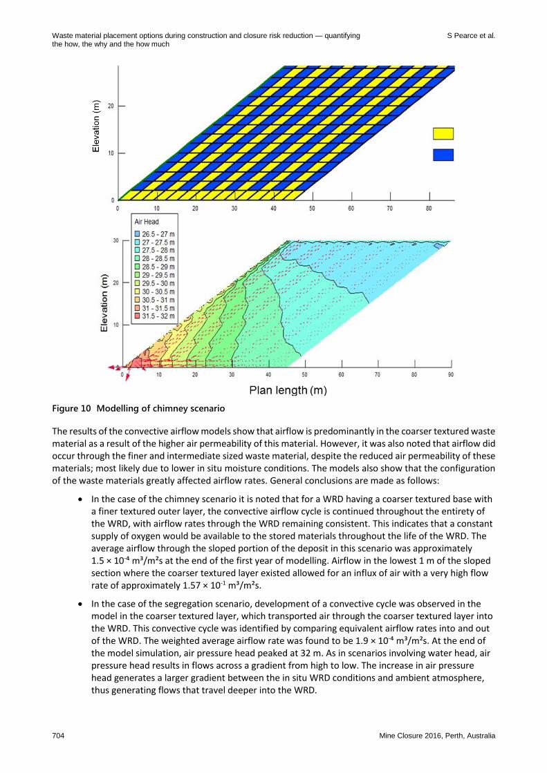
‘Chimney’ scenario: alternating layers of finer and coarser textured material sloped at the angle of repose, shown in Figure 10.
‘Segregation’ scenario: simulates gravitational segregation of the waste material into texture layers due to a high tip height (i.e. coarser waste material has a propensity to roll to the base of a slope while finer material stays near the top of the slope).
‘Compaction’ scenario: simulates an OSA built from the bottom up with alternating layers of 10 m of PAF/NAF topped with 2 m of NAF. The top 0.2 m of the PAF material at NAF/PAF interface is estimated to be compacted due to haul truck traffic while placing the NAF layer.
Waste material placement options during construction and closure risk reduction — quantifying S Pearce et al. the how, the why and the how much
704 Mine Closure 2016, Perth, Australia
Figure 10 Modelling of chimney scenario
The results of the convective airflow models show that airflow is predominantly in the coarser textured waste material as a result of the higher air permeability of this material. However, it was also noted that airflow did occur through the finer and intermediate sized waste material, despite the reduced air permeability of these materials; most likely due to lower in situ moisture conditions. The models also show that the configuration of the waste materials greatly affected airflow rates. General conclusions are made as follows:
In the case of the chimney scenario it is noted that for a WRD having a coarser textured base with a finer textured outer layer, the convective airflow cycle is continued throughout the entirety of the WRD, with airflow rates through the WRD remaining consistent. This indicates that a constant supply of oxygen would be available to the stored materials throughout the life of the WRD. The average airflow through the sloped portion of the deposit in this scenario was approximately 1.5 × 10-⁴ m³/m²s at the end of the first year of modelling. Airflow in the lowest 1 m of the sloped section where the coarser textured layer existed allowed for an influx of air with a very high flow rate of approximately 1.57 × 10⁻¹ m³/m²s.
In the case of the segregation scenario, development of a convective cycle was observed in the model in the coarser textured layer, which transported air through the coarser textured layer into the WRD. This convective cycle was identified by comparing equivalent airflow rates into and out of the WRD. The weighted average airflow rate was found to be 1.9 × 10-⁴ m³/m²s. At the end of the model simulation, air pressure head peaked at 32 m. As in scenarios involving water head, air pressure head results in flows across a gradient from high to low. The increase in air pressure head generates a larger gradient between the in situ WRD conditions and ambient atmosphere, thus generating flows that travel deeper into the WRD.

Geochemistry and mine waste
Mine Closure 2016, Perth, Australia 705
In the case of the compaction model in first year of the model simulation, airflow rates were relatively constant, and reached a peak of 3.0 × 10-⁶ m³/m²s during this time. The weighted average airflow rate was found to be 1.55 × 10-⁶ m³/m²s. Following 20 years runtime in the numerical model, air pressure head in the WRD peaked at 38 m. Despite air pressure head values in the scenario proving to be much larger than the results of the segregated material types, airflow rates were lower. This is due to the presence of compacted layers between each layer of deposited material, limiting airflow from breaching into the overlying layer and continuing the convective cycle. In effect, the convective airflow is ‘shut down’ by these compacted layers.
The air flow rates calculated by numerical modelling are in very good agreement with site data and indicate that where coarse basal zones are present, air flux rates through waste mass of around 1–2 × 10-⁴ m³/m²s can be expected. Based on typical sulphide oxidation rates, the oxygen flux that derived from gas flux of this magnitude is sufficient to allow oxidation to occur at rates similar to that observed in laboratory kinetic tests such as AMIRA leach columns. This is to say that although field oxidation rates are likely to be lower than laboratory rates because of various scaling factors, oxygen supply may not be the limiting factor in these cases. The modelling also agrees with site data that shows that the use of compacted finer textured layers and short lift heights significantly reduces the potential for air flux and, therefore, is a limiting factor for oxidation rates.
5 FS in design – shutting the door before the horse has bolted
With constant developments and improvements in the field of risk modelling and assessment, the focus should now be translating model results into practical, site-specific construction methods. This allows progressive risk management solutions to be adopted during construction rather than relying on final closure solutions like covers or treatment systems which have an inherently low FS in design. Field data and numerical modelling of data from mines in the Pilbara showing oxygen ingress increasing at the toe of dumps and through basal rubble zones should directly inform the development of a risk mitigation methods.
An example of how waste placement solutions can be defined on this basis is shown in Figure 11. The construction of toe bunds of inert material ahead of the coming tip head, along with paddock dumped and compacted layers on lift surfaces, should limit oxygen ingress significantly, and therefore limit the oxidation of the waste material during the WRD construction. In identifying the dominant factors in closure risks such as AMD, WRD construction and placement techniques may be considered on a case-by-case basis, rather than a generic model which does not account for climatic, geological and volumetric material variations and may lead to unforeseen and costly failures during life-of-mine.
Figure 11 Risk management methods for WRD construction, shown in cross-section and plan view

Waste material placement options during construction and closure risk reduction — quantifying S Pearce et al. the how, the why and the how much
706 Mine Closure 2016, Perth, Australia
6 Conclusion
Closure risks related to waste rock placements such as AMD, gas generation, and potential for spontaneous combustion risks develop through complex and interrelated processes within WRDs. While detailed geochemical assessments and classifications of waste materials are important factors, physical properties and waste placement techniques have a significant influence on the oxygen ingress and water flow through these facilities. Therefore, potential oxidation and subsequent release of AMD and/or gas may be reduced when placement techniques and construction methods are assessed in relation to site specific conditions and material types.
Site data collection, analytical modelling based on site-specific data, where available, and numerical assumptions developed from literature reviews and conceptual models, can be utilised to assess waste placement methods to determine how closure risks can be appropriately managed. Risk limits can then be applied forming ‘acceptability limits’ or cut-offs. This information can then be incorporated into WRD design in order to construct facilities depending on the risks and limitations at each site, with the aim to minimise closure risks both during construction and following closure. This allows progressive risk management solutions to be adopted during construction rather than relying on final closure solutions like covers or treatment systems which have an inherently low FS in design.
References
Brown, PL, Logsdon, MJ, Vinton, B, Schofield, I & Payne, K 2014, ‘Detailed characterisation of the waste rock dumps at the Kennecott Utah Copper Bingham Canyon Mine – Optionality for Closure’, in H Miller & L Preuss (eds) Proceedings of the Eighth Australian Workshop on Acid and Metalliferous Drainage, Adelaide, pp 1–12.
Lottermoser, BG 2010, Mine wastes characterization, treatment and environmental impacts, third edition, Springer, Berlin. Morin, KA, Gerencher, E, Jones, CE & Konasewich, DE 1991, ‘Critical Literature Review of Acid Drainage from Waste Rock’, MEND
Report 1.11.1. Nichols, RS 1986, ‘Rock segregation in waste dumps’, in Proceedings of the International Symposium on Flow-Through Rock Drains,
Cranbrook, B.C., Canada. Pearce, SR 2014, ‘Beyond the PAF Cell’, in H Miller & L Preuss (eds), Proceedings of the Eighth Australian Workshop on Acid and
Metalliferous Drainage, JK Tech, Indooroopilly, Australia, pp. 97–110. Pearce, S & Barteaux, M 2014a, ‘Instrumentation in waste rock dumps: Going deeper’, in H Miller & L Preuss (eds) Proceedings of the
Eighth Australian Workshop on Acid and Metalliferous Drainage, Adelaide, pp 371–386. Pearce, S & Barteaux, M 2014b, ‘Instrumentation of waste rock dumps as part of integrated closure monitoring and assessment’, in
Proceedings of 9th International Conference on Mine Closure, Johannesburg. Pearce, SR & Lehane, S 2015, ‘Quantitative risk assessment tools to assist with waste management and placement guidelines’ in AB
Fourie, M Tibbett, L Sawatsky & D van Zyl (eds), Mine Closure 2015 Proceedings of the 10th International Conference on Mine Closure, Vancouver.
Pearce, SR, Beavis, FR, Winchester, SJ & Thompson, H 2012, ‘Managing closure risks by integrating acid and metalliferous drainage assessments with mine scheduling – real world applications’, in AB Fourie & M Tibbett (eds), Mine Closure 2012 Proceedings of the Seventh International Conference on Mine Closure, Australian Centre for Geomechanics, Perth, pp. 801–814.
Wilson, W 2011, ‘Rock Dump Hydrology: An overview of full-scale excavations and scale-up experiments conducted during the last two decades’, in LC Bell & B Braddock (eds), Proceedings of the Seventh Australian Workshop on Acid and Metalliferous Drainage, pp 307–322.