Embed Size (px)
Citation preview
WASHING MACHINESERVICE MANUAL READ THIS MANUAL CAREFULLY TO DIAGNOSE TROUBLECORRECTLY BEFORE OFFERING SERVICE.
MODEL : WD-803(4)0(W)(F)(H)WD-803(4)0F(H)(B)WD-1042F(H)(B)WD-1041(3)F(H)(B)WD-102(4)1(5)W(F)(H)WD-102(4)(5)F(H)(B)WD-1223(5)F(H)(B)WD-1243(5)F(H)(B)
CAUTION
website : http://www.LGEservice.com
e-mail : http://LGEservice.com/techsup.html

JUN. 2001 PRINTED IN KOREA P/No.:3828ER3008A

2
CONTENTS
1. SPECIFICATION............................................................................................................................3
2. FEATURES & TECHNICAL EXPLANATION ................................................................................ 4
3. PARTS IDENTIFICATION ............................................................................................................ 6
4. INSTALLATION............................................................................................................................. 7
5. OPERATION ................................................................................................................................10
6. WIRING DIAGRAM .....................................................................................................................18
7. PROGRAM CHART .....................................................................................................................19
8. TROUBLESHOOTING.................................................................................................................20
8-1. BEFORE PERFORMING SVICE ........................................................................................20
8-2. QC TEST MODE.................................................................................................................20
8-3. HOW TO KNOW THE WATER LEVEL FREQUENCY........................................................21
8-4. ERROR DISPLAY ...............................................................................................................22
9. ERROR DIAGNOSIS AND CHECK LIST ....................................................................................26
9-1. DIAGNOSIS AND ANSWER FOR ABNORMAL OPERATION ...........................................26
9-2. FAULT DIAGNOSIS AND TROUBLESHOOTING ..............................................................29
10. DISASSEMBLY INSTRUCTIONS .............................................................................................39
11. EXPLODED VIEW AND PART LIST ..........................................................................................47
11-1. THE EXPLODED VIEW OF CABINET ASSEMBLY..........................................................47
11-2. THE EXPLODED VIEW OF CONTROL PANEL & DISPENSER ASSEMBLY..................48
11-3. THE EXPLODED VIEW OF DRUM & TUB ASSEMBLY...................................................49
APPENDIX(Replacement parts list) ........................................................................................... 50

3
1. SPECIFICATION
ITEM
WD-1223(5)F(H)(B)WD-1243(5)F(H)(B)WD-1041(3)F(H)BWD-1042F(H)BWD-102(4)1F(H)BWD-803(4)0F(H)B
63kg
120W
67kg
190W
220V - 240V~, 50Hz
300W
32W
2000W
45 rpm
0.3-10kgf/cm2 (30-1000kPa)
Electronic
7.0kg
Wool (2.0kg), Synthetic (4.0), Delicate (3.0kg)
600mm (W) x 600mm (D) x 850mm (H)
Automatic type by pressing the button
9 steps (by sensor)
Adapted
Adapted
Adapted
10 ITEMS 7 ITEMS
Adapted
Adapted
Adapted
Normal, Super, Normal+Rinse Hold,
Super+Rinse Hold
600/800/1000/1200 rpm400/600/800/1000 rpm[WD-1041(3)F(H)B / WD-1042F(H)B /WD-102(4)1(5)F(H)B]No Spin/500/800 rpm[WD-803(4)0F(H)B]
600/800/1000 rpm
No Spin/500/800 rpm[WD-803(4)0(W)(F)(H)]
Coloreds, Whites, Rapid, Synthetic, Wool, Delicate
ELECTRICITYCONSUMPTION
REVOLUTIONSPEED
OPERATION WATER PRESSURE
CONTROL TYPE
WASH CAPACITY
DIMENSION
WASH PROGRAM
RINSE PROGRAM
DOOR SWITCH TYPE
WATER LEVEL
SENSING OF THE LAUNDRY AMOUNT
NEURO - FUZZY
DISPLAY OF THE REMAINING TIME
DIAGNOSIS ERROR
POWER AUTO OFF
AUTO RESTART
CHILD LOCK
POWER SUPPLY
PRODUCT WEIGHT
WASHING
SPIN (800rpm)
DRAIN MOTOR
WASH HEATOR
WASH
SPIN
WD-803(4)0(W)(F)(H)WD-102(4)1W(F)(H)WD-1042F(H)

4
Jumbo drumJumbo drum can wash about 40% more per load thanconventional washing machine. A bigger drum improves thewash performance.
More economical by Fuzzy Logic SystemFUZZY Logic System detects the amount of load and watertemperature, and then determines the optimum water leveland washing time to minimize energy and waterconsumption.
Child-LockThe Child-Lock system has been developed to preventchildren from pressing any button to change the programmeduring operation.
Low noise speed control systemBy sensing the amount of load and balance, automatical
distributes load evenly to minimize the spinning noise level.
Auto RestartAlthough the washing machine is turned off by a power failure,it restarts automatically where it stopped process when poweris supplied again. It will be the same when the machine isunplugged and is plugged in again.
2. FEATURES & TECHNICAL EXPLANATION
2-1.FEATURES
40%
(Water Temp) (Time Delay)

5
2-2.DETERMINE WASHING TIME BY FUZZY LOGICTo get the best washing performance optimal time is determined by sensing of water temperature,
selected washing temperature and laundry amount.
2-3.WATER LEVEL CONTROLThis model adopts a pressure sensor which can sense the water level in the tub.
When the water level reaches to the preset level the water supply is stopped, then the washing program proceeds.
Spinning does not proceed until the water in the tub reduces a certain level.
2-4.THE DOOR CAN NOT BE OPENEDWhile program is operating.
While Door Lock light turns on.
FUZZYLOGIC
laundryamount
selectedwashing
temperature
watertemperature
washing time
rinse time
spin rhythm, time
the bestwashingperformance
SENSING PROCESSING DETERMINATION EFFECT

6
3. PARTS IDENTIFICATION
Emergency door releaseDrain plug (Cap,Remaing Hose)
Drawer
Drum
Drain hose
Drain pump filter
(For detergent and fabric softener)
Power plug
Control panel
Door
Adjustable feet
Lower cover
Lower cover cap
• If the supply cord is damaged, it must be replaced by the manufacturer or its service agents or a similarly qualified person in order to avoid a hazard.
ACCESSORIES* Option : Cold - 1EA
Cold/Hot - 2EA
Inlet hose Wrench(1EA)

7
Before servicing ask the customer what the trouble is.Check the adjustment (power supply is 220-240V, remove the transit bolts....)Check the troubles referring to the troubleshooting.Decide service steps referring to disassembly instructions.Then, service and repair.After servicing, operate the appliance to see whether it works O Kor NOT.
STANDARD INSTALLATIONThe appliance should be installed as follows.
Remove the transit bolts Turn the adjustable feet to(4EA: ) with supplied spanner. set the appliance horizontally.
Keep the transit bolts and
spanner for future use.
The appliance goes up by
rotating the feet clockwise.
The appliance comes down by
rotating the feet counter-
clockwise.
4. INSTALLATION
1
High
Low
REMOVE THE TRANSIT BOLTS
INSTALL THE APPLIANCE ONFLAT AND FIRM SURFACE
ADJUST THE HORIZONTAL

8
HOW TO CONNECT INLET HOSE
Check that the rubber washer is inside of the
valve connector.
Connect the inlet hose firmly to prevent leak.
CONNECT DRAIN HOSE
CONNECT POWER PLUG
Make sure that the hose is not twisted.
The drain hose should be placed under 100cm from the floor.
Connect the power plug to the wall outlet. Avoid connecting several electric devices, It may be the cause of a fire.
Avoid submerging the end of the hose.

9
TEST OPERATION
Pre 12001000800600no Spin
MainSuper Normal
Rinse hold
P
(Wash) (Rinse) (Spin)
Connect the power plug tothe outlet.Connect the inlet hose.
Troubleshooting refer to (8-4.ERROR DISPLAY)Assemble and disassemble refer to (10.Disassembly Instructions)
Preparation for washing.
Press the POWER ( )button.
Press the PROGRAM ( ) button.
Press the (START/PAUSE)( ) button.
·In case of coloredsprogram.
·In case of coloredsprogram.
·Press the button (WATER TEMP) ( ) and then the present temperature in displayed.
·Check if the drum rotates to clockwise and counterclockwise.
·Check shower because thewater supplied on the doorat first.
·After power off, press the DOOR OPEN ( ) button to check the door open.
·If SVC is needed, during check and removethe remaining water by pulling out the hose cap.
Check the water heating. Check automatic reverse Check the water supply.turn.
Check the drain and spin Power off Water removal
P

10
5. OPERATION
(Wash) (Rinse) (Spin) (Water Temp) (Time Delay)
Pre R H
S
N
TT
Main
1200(1000)1000(800)800(600)600(400)no Spin
50
3040
Cold
60
95
How to set the Function
Rinse hold• Rinse hold function can be selected by pressing the rinse
( ) button, and rinse hold lamp turns ON.• Selection rinse hold washer waits without drain / spinning
after rinse.• To drain and spin, press rinse ( ) button, rinse hold lamp
turns off and drain / spinning starts.
How to select water temperature
• Press the button to select water temperature.
• The water temperature can be selected [40°C→ 50°C→ 60°C→Cold→ 30°C ] duringcoloreds, or synthetic programs.
• 95°C is selected only for whites program.
• By pressing the button while operating the
present temperature is displayed.
How to use delayed washing
• Press the button when reservation washing is needed.
• When the button is pressed, 3:00ais displayed. A maximumdelay of 19:00ahours can be set.
• Whenever pressing it, one hour increases.
• ~ Time delay ₩the power ( ) button to cancel it.
• ~ Time delay ₩means the time required from the present to thecompletion of washing.
Displaying abnormal operation• Display the remaining time (Hour : Minute)• The remaining time is reduced by the washing cycle.
• Error lamp is indicated the abnormal operation.
( )
• Display the reservation time.
For manual wash,rinse, and spin
• Use these buttons to changewashing method, rinsemethod spinning speed.
• When lamp is off, no selectionhas been made.
• Prewashing is available forcoloreds, whites, andsynthetic program.
WD-1223(5)F(H)(B) / WD-1243(5)F(H)(B)
WD-1041(3)F(H)B / WD-102(4)1(5)F(H)B
, , , , ,,

11
y) (Program)
(Start/Pause)
(Power)
(Door open)
C S
iW W
R D
Door lockP
How to select a program
• 6 programs can be selected by the kind of the laundry.
• By pressing the program ( ) button, [Coloreds→Whites→Rapid→Delicate→Wool→Synthetic] can be
selected.
How to open the door• Use the button to add the
laundry.
• Press the button to openthe door.
• Only operates when thepower plug is connected to
220-240V~ outlet.
Door lock displayChild-Lock• It shows whether the door
can be open or not during thewashing cycle.
• If the lamp is off, the doorcan be opened.
• Once Child-Lock is set, all buttons are inoperableduring operation.
• The Child-Lock system can be set at any timeeven including during Power Off, on Pause andoperation. It is automatically cancelled when anoperational error occur and when the cycle ends.
• When power is off, the LED indicates~ ₩only.During operation, or when the program paused theLED Will indicate~ ₩and the remaining time.
Error display
• The display blinks if there is an error.
• no inlet : Trouble with water supply.
• imbalance : The laundry is tilted to one side.
• no drain : The drain filter is clogged or the drainpump is out of order.
Power button• By pressing the button, it
repeats turning on and off.
• Press the button to cancelthe time delay.
• It turns off in 8 sec. after theprogram is finished.
Start/Pause button• Use the button to start or
pause wash cycle.
• The power turns offautomatically in 4 minutesafter the pause button ispressed.
• Press the button to changethe program.
P

12
WD-1021(5)W(F)(H)/WD-1041(5)W(F)(H)
Wash Rinse Spin Water Temp.
TiDe
How to set the Function
Rinse hold• Rinse hold function can be selected by pressing the rinse
button, and rinse hold lamp turns ON.• Selection rinse hold washer waits without drain / spinning after
rinse.• To drain and spin, press rinse button, rinse hold lamp
turns off and drain / spinning starts.
How to select water temperature• Press the button to select water temperature.
• The water temperature can be selected [40°C→ 60°C→ Cold ] during coloreds, or syntheticprograms.
• 95°C is selected only for whites program.
• By pressing the button while operating the
present temperature is displayed.
How to use delayed washing• Press the button when reservation washing is needed.
• When the button is pressed, ais displayed. A maximum delay of ahours can be set.
• Whenever pressing it, one hour increases.
• Use the power button to cancel it.
• ~ Time delay ₩means the time required from the presentto the completion of washing.
Displaying abnormal operation• Display the remaining time (Hour : Minute)• The remaining time is reduced by the washing cycle.
• Error lamp is indicated the abnormal operation.
( )
• Display the reservation time.
For manual wash,rinse, and spin
• Use these buttons to changewashing method, rinsemethod spinning speed.
• When lamp is off, no selectionhas been made.
• Prewashing is available forcoloreds, whites, andsynthetic program.
,,

13
TimeDelay Program
StartPause
Power
DoorOpen
Door lock
How to select a program
• 6 programs can be selected by the kind of the laundry.
• By pressing the program button, [Coloreds → Whites→ Rapid → Delicate → Wool → Synthetic] can beselected.
How to open the door• Use the button to add the
laundry.
• Press the button to openthe door.
• Only operates when thepower plug is connected to
220-240V~ outlet.
Door lock displayChild-Lock• It shows whether the door
can be open or not during thewashing cycle.
• If the lamp is off, the doorcan be opened.
• Once Child-Lock is set, all buttons are inoperableduring operation.
• The Child-Lock system can be set at any timeeven including during Power Off, on Pause andoperation. It is automatically cancelled when anoperational error occur, and when the cycle ends.
• When power is off, the LED indicates~ ₩only.During operation, or when the program paused theLED Will indicate~ ₩and the remaining time.
Error display• The display blinks if there is an error.
• no inlet : Trouble with water supply.
• imbalance : The laundry is tilted to one side.
• no drain : The drain filter is clogged or the drainpump is out of order.
Power button• By pressing the button, it
repeats turning on and off.
• Press the button to cancelthe time delay.
• It turns off in 8 sec. after theprogram is finished.
Start/Pause button• Use the button to start or
pause wash cycle.
• The power turns offautomatically in 4 minutesafter the pause button ispressed.
• Press the button to changethe program.

14
WD-8030(W)(F)(H)/WD-8040(W)(F)(H)/WD-1042F(H)
PreRinse Hold
800
600
no Spin
(1000)
(800)
(600) Child lo
EcoSuperNormalMain
95 C60 C40 CCold
Wash Rinse Spin WaterTemp Eco
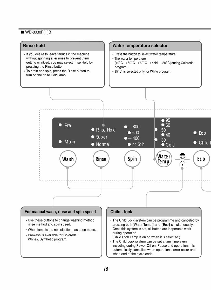
Water temperature selector
Press the button to select water temperature.
The water temperature [40。C 60。C cold] during coloreds program.
95。C is selected only for White program.
For manual wash, rinse and spin speed
Use these buttons to change washing method,rinse method and spin speed.
When lamp is off, no selection has been made.
Prewash is available for Coloreds, Whites, Synthetic program.
Rinse hold
If you desire to leave fabrics in the machine withoutspinning after rinse to prevent them getting wrinkled,you may select rinse Hold by pressing the Rinsebutton.
To drain and spin, press the rinse button to turn offthe rinse Hold lamp.
Child - lock
The Child Lock system can be programme and canceledby pressing both~Water Temp.₩and ~Eco₩simultaneously.Once this system is set, all button are inoperable workduring operation.(Child Lock Lamp is on on when it is selected.)
The Child Lock system can be set at any time evenincluding during Power-Off on. Pause and operation. It isautomatically cancelled when operational error occur andwhen end of the cycle ends.
16WD-1042F(H)

15
d lock
Coloreds
Whites
Rapid
Synthetic
Wool
Delicate
Pro-gram
StartPause
DoorOpen
Door Lock
Wash program selector
6 programs can be set depending on thetype of the laundry.If the power button is pressed.Coloreds program is automatically set.By pressing the button, [ Coloreds Whites Rapid Delicate Wool Synthetic] can be selected.
Start/Pause button
Use the button to start orpause wash cycle.The power turns offautomatically 4 minutesafter the pause button ispressed.
Door lock display
It shows whether the doorcan be open or not duringthe washing cycle.If the light is off, the doorcan opened.
Door lock display
Press the button to openthe door.Only operate when powerplug is connected.
Eco button
If you press the Eco button in whileWhites program, Eco function isselected. Eco function gives you almostthe same washing effect as that in 95with less energy consumption.
Power button
Press the button to turn poweron and off.
16
WD-8030F(H)B
PreRinse Hold
800
400600
no Spin Child lo
EcoSuperNormalMain
95 60 50 4030 Cold
Wash Rinse Spin WaterTemp Eco
Water temperature selector
Press the button to select water temperature.The water temperature [40。C 50。C 60。C cold 30。C] during Coloredsprogram. 95。C is selected only for White program.
For manual wash, rinse and spin speed
Use these buttons to change washing method,rinse method and spin speed.
When lamp is off, no selection has been made.
Prewash is available for Coloreds, Whites, Synthetic program.
Rinse hold
If you desire to leave fabrics in the machinewithout spinning after rinse to prevent themgetting wrinkled, you may select rinse Hold bypressing the Rinse button.To drain and spin, press the Rinse button toturn off the rinse Hold lamp.
Child - lock
The Child Lock system can be programme and canceled bypressing both~Water Temp.₩and ~Eco₩simultaneously.Once this system is set, all button are inoperable workduring operation.(Child Lock Lamp is on on when it is selected.)The Child Lock system can be set at any time evenincluding during Power-Off on. Pause and operation. It isautomatically cancelled when operational error occur andwhen end of the cycle ends.
16

17
d lock
Coloreds
Whites
Rapid
Synthetic
Wool
Delicate
Pro-gram
StartPause
DoorOpen
Door Lock
Wash program selector
6 programs can be set depending on thetype of the laundry.If the power button is pressed.Coloreds program is automatically set.By pressing the button, [ Coloreds Whites Rapid Delicate Wool Synthetic] can be selected.
Start/Pause button
Use the button to start orpause wash cycle.The power turns offautomatically 4 minutesafter the pause button ispressed.
Door lock display
It shows whether the doorcan be open or not duringthe washing cycle.If the light is off, the doorcan opened.
Door lock display
Press the button to openthe door.Only operate when powerplug is connected.
Eco button
If you push the Eco button in whileWhites program, Eco function isselected. Eco function gives you almostthe same washing effect as that in 95with less energy consumption.
Power button
Press the button to turn poweron and off.

18
6. WIRING DIAGRAM
GN/YL(GN)
GN/YL(GN)
GN/YL(GN)
GN/YL(GN)
WD-1223(5)F(H)(B) / WD-1243(5)F(H)(B) / WD-1041(2)(3)F(H)B WD-102(4)1(5)F(H)B / WD-803(4)0F(H)B
(option)
WD-803(4)0(W)(F)(H) / WD-102(4)1(5)W(F)(H) / WD-1042F(H)

19
7. PROGRAM CHART
WD-1041(3)F(H)B/803(4)0F(H)B/102(4)2F(H)B/102(4)5F(H)B
About 2:23
About 41
About 1:07
About 45
WD-8030(4)(W)(F)(H) / WD-102(4)1(5)W(F)(H) / WD-1042F(H) / WD-1223(5)F(H)(B) WD-1243(5)F(H)(B)

20
8-1.BEFORE PERFORMING SERVICE Be careful of electric shock or disconnecting the parts while troubleshooting.
Voltage of each terminal in AC 220-240V and DC while applying an electric current.
8-2.QC TEST MODE.① Pressing RINSE ( ), and SPIN ( ) button simultaneously.
② Power supply ON with pressing upper two button. then buzzer sound twice.
③ Press the START/PAUSE ( ) button as follows.
~Press the START/PAUSE ( ) button more 4 times until stop spinning₩
8. TROUBLESHOOTING
Pressing number of[START/PAUSE]button Checking Point Display Status
None All lamps turn on
1 time Clockwise spin (right) Motor rpm (About 45)
2 times Low speed spin Motor rpm (About 63~67)
3 times High speed spin Motor rpm (About 114~117)
4 times Inlet valve for pre-wash operation Water level frequency (25~65)
5 timesInlet valve for main-wash operation
Water level frequency (25~65)Hot inlet valve in case of hot water fill
6 times Inlet valve for main-wash operation Water level frequency (25~65)
7 times Counterclockwise spin (left) Motor rpm (About 45)
8 times A Heater is in operation for 3 sec. Water Temperature
9 times Draining pump operation Water level frequency
10 times Auto off operation
WD-1223(5)F(H)(B) / WD-1243(5)F(H)(B) / WD-102(4)1(5)W(F)(H) WD-102(4)1(5)F(H)B / WD-1041(3)F(H)B

21
8-3. HOW TO KNOW THE WATER LEVEL FREQUENCY WD-1223(5)F(H)(B)/WD-1243(5)F(H)(B)/WD-102(4)1(5)W(F)(H) / WD-1041(3)F(H)B
Press the WASH and RINSE button simultaneously.
ex) 241 : Water level frequency = 241× 10-1= 24.1
The digits means water level frequency (10-1 )
Times of press Checking Point
None
1 time
2 times
3 times
4 times
5 times (FOR WD-****FH)
6 times
7 times
8 times
9 times
10 times
All lamps turn on
Counterclockwise spin
Low speed Spin
High speed Spin
Inlet valve for pre-wash operation (Cold)
Inlet valve for main-wash operation (Hot)
Inlet valve for main-wash operation (Cold)
Clockwise spin
The Heater is in operation for 3 sec.
Draining pump operation
Auto off operation
WD-803(4)0(W)(F)(H) / WD-803(4)0F(H)(B) / WD-102(4)2F(H)(B)

22
ERROR SYMPTOM CAUSE
1 WATER INLET Water has not reached to the pre-set level within 4 min. since
ERROR inlet valve operated, or water has not reached to the normal
level within 25 min.
2 IMBALANCE The appliance is tilted.
ERROR Laundry is gathered to one side.
Non-distributable things are put into the drum.
3 DRAIN ERROR Water has not drained enough within 5 min.
4 OVERFLOW Water is automatically being pumped out because too much
ERROR water is in the tub.
5 SENSOR PRESSURE
S/W ERRORThe sensor pressure switch is out of order.
6 DOOR OPEN The ~Start/Pause₩ button is pressed with the door open.ERROR The door switch is out of order.
7 HEATING The thermistor is out of order.
ERROR
8 SENSOR The connector (5-pin, male, white) in the wire harness is not
ERROR connected to the connector (5-pin, female) of hall sensor in
the MOTOR.
’ Reconnect or repair the contact in the connector.
8-4. ERROR DISPLAY. WD-1223(5)F(H)(B)/WD-1243(5)F(H)(B)/WD-102(4)1(5)WF(H) / WD-1041(3)F(H)B
If you press the ~Start/Pause₩ button when an error in displayed, any error except will disappear and the machine will change into pause status.In case of d e, d e, d e, if the error is not resolved within 20 sec. In the case of other errors, if the error is not resolved within 4 min. power will be turned off automatically and the error code will blink.But in case of dFEe, power will not be turned off.
imbalance
no drain
no inlet

23
ERROR SYMPTOM CAUSE
8
9
10
• The electric contact between the connectors
(5-pin, male in the wire harness and 5-pin female in the hall sensor)
is bad or unstable.
Reconnect or repair the contact in the connector.
• The connector (6-pin, male, natural) in the wire harness is not
connected to the connector (6-pin, female, natural) of PWB assembly
(Main) or the electric contact of connectors is bad/unstable.
Reconnect or repair the contact in the connector.
• The electric contact between the connectors ~6-pin, male in the wire
harness and 6-pin female in the controller (Main)₩is bad or unstable.
Reconnect or repair the contact in the connector.
• The wire harness between hall sensor in the MOTOR and PWB
assembly (Main) is cut (open circuited).
Repair/replace the damaged WIRE HARNESS.
• The hall sensor is out of order/defective.
Replace the motor.
• The controller (Main) is out of order/defective.
Replace the PWB assembly (Main).
• PWB assembly (Main) is out of order.
Replace the PWB assembly (Main).
• Winding in the MOTOR is short-circuited.
Replace the MOTOR.
• The connector (3-pin, male, white) in the wire harness is not connected
to the connector (3-pin, female, white) of MOTOR.
Reconnect or repair the connector.
• The electric contact between the connectors ~3-pin, male, white in the
wire harness and 6 pin, female, white in the PWB assembly (Main)₩
is bad or unstable.
Reconnect or repair the contact in the connector.
• The wire harness between the MOTOR and PWB assembly (Main)
is cut (open circuited).
Repair the damaged (open-circuited) WIRE HARNESS.
• The hall sensor is out of order/defective.
Replace the PWB assembly (Main).
SENSOR
ERROR
CURRENT
ERROR
LOCK
ERROR

24
WD-8030(W)(F)(H)/WD-8040W(F)(H)/WD-1042F(H)/WD-803(4)0F(H)B/WD-102(4)2F(H)BIf you press the ~Start/Pause₩button when an error in displayed, any error except SENSOR PRESSURE S/W ERROR will disappear and the machine will change into pause status.In case of dSENSOR PRESSURE S/W ERROR, THERMISTOR ERROReif the error is not resolvedwithin 20 sec. In the case of other errors, if the error is not resolved within 4 min. power will be turnedoff automatically and the error code will blink. But in case of dOVER FLOW ERRORe, power will notbe turned off.
95 C
60 C 40 C Cold
Door Lock
800600no Spin
(1000)(800)(600) ※( ) :WD-1042F(H)
Pre
Main
forWD-8030F(H)BWD-8040F(H)BWD-1022F(H)BWD-1042F(H)B
1000800600400no spin
Rinse HoldSuperNormal
forWD-8030F(H)BWD-8040F(H)BWD-1022F(H)BWD-1042F(H)B
95 60
50 40
30 Cold
ColoredsWhitesRapid
Synthetic
WoolDelicate
ERROR SYMPTOM CAUSE
1 WATER INLET Water has not reached to the pre-set level within 4 min. sinceERROR inlet valve operated, or water has not reached to the normal
level within 25 min.
2 IMBALANCE The appliance is tilted. ERROR Laundry is gathered to one side.
Non-distributable things are put into the drum.
3 DRAIN ERROR Water has not drained enough within 5 min.
4 OVERFLOW Water is automatically being pumped out because too muchERROR water is in the tub.
5 SENSOR PRESSURES/W ERROR
The sensor pressure switch is out of order.
6 DOOR OPEN The Start/Pause button is pressed with the door open.ERROR The door switch is out of order.
7 THERMISTORERROR The thermistor is out of order.

25
• The electric contact between the connectors
(5-pin, male in the wire harness and 5-pin female in the hall sensor) is
bad or unstable.
Reconnect or repair the contact in the connector.
• The connector (6-pin, male, natural) in the wire harness is not connected
to the connector (6-pin, female, natural) of PWB assembly (Main) or the
electric contact of connectors is bad/unstable.
Reconnect or repair the contact in the connector.
• The electric contact between the connectors ~6-pin, male in the wire
harness and 6-pin female in the controller (Main)₩is bad or unstable.
Reconnect or repair the contact in the connector.
• The wire harness between hall sensor in the MOTOR and PWB
assembly (Main) is cut (open circuited).
Repair/replace the damaged WIRE HARNESS.
• The hall sensor is out of order/defective.
Replace the motor.
• The controller (Main) is out of order/defective.
Replace the PWB assembly (Main).
• PWB assembly (Main) is out of order.
Replace the PWB assembly (Main).
• Winding in the MOTOR is short-circuited.
Replace the motor.
• The connector (3-pin, male, white) in the wire harness is not connected
to the connector (3-pin, female, white) of MOTOR.
Reconnect or repair the connector.
• The electric contact between the connectors ~3-pin, male, white in the
Wire Harness and 6-pin, female, white in the PWB assembly (Main)₩
is bad or unstable.
Reconnect or repair the contact in the connector.
• The wire harness between the MOTOR and PWB assembly (Main)
is cut (open circuited).
Repair the damaged (open-circuited) WIRE HARNESS.
• The hall sensor is out of order/defective.
Replace the PWB assembly (Main).
SENSOR
ERROR
CURRENT
ERROR
LOCK
ERROR
forWD-8030F(H)B / WD-8040F(H)BWD-1022F(H)B / WD-1042F(H)B
Rinse HoldSuperNormal
800600400no spin
(1000)
Pre
forWD-8030F(H)B / WD-8040F(H)BWD-1022F(H)B / WD-1042F(H)B
Main
Rinse HoldSuperNormal
forWD-8030F(H)B / WD-8040F(H)BWD-1022F(H)B / WD-1042F(H)B
(1000)800600400no spin
95 60
50 40
30 Cold
ERROR SYMPTOM CAUSE
8
9
10
26
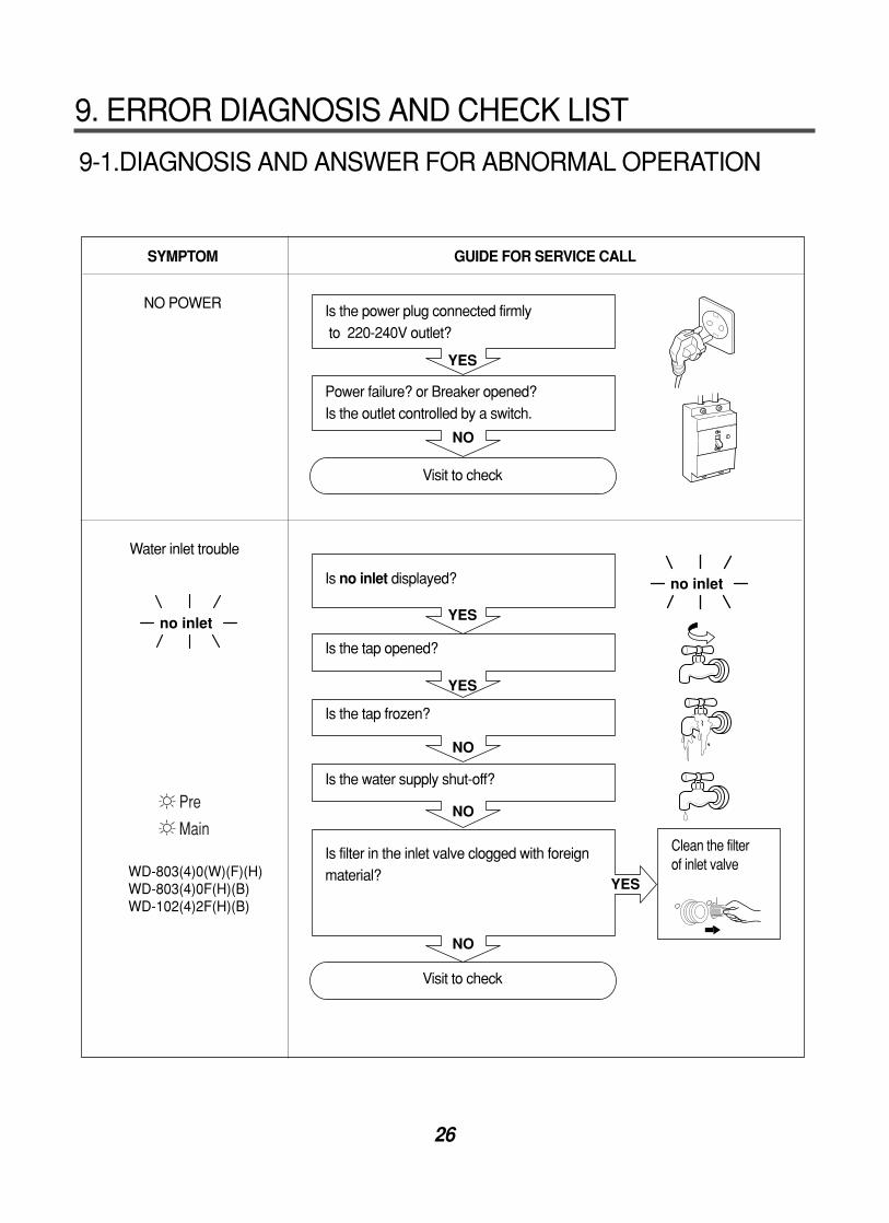
9-1.DIAGNOSIS AND ANSWER FOR ABNORMAL OPERATION
SYMPTOM GUIDE FOR SERVICE CALL
NO POWER
Water inlet trouble
YES
YES
YES
NO
NO
YES
NO
NO
no inlet
no inlet
Is the power plug connected firmlyto 220-240V outlet?
Power failure? or Breaker opened?Is the outlet controlled by a switch.
Visit to check
Is no inlet displayed?
Is the tap opened?
Is the tap frozen?
Is the water supply shut-off?
Is filter in the inlet valve clogged with foreignmaterial?
Visit to check
Clean the filter of inlet valve
9. ERROR DIAGNOSIS AND CHECK LIST
Pre
Main
WD-803(4)0(W)(F)(H) WD-803(4)0F(H)(B)WD-102(4)2F(H)(B)

27
SYMPTOM GUIDE FOR SERVICE CALL
°Door open trouble°Error displayed on the
program
°Drain trouble
NO
NO
YES
YES
YES
NO
NO
NO
no drain
no drain
YES
When the door opened, Is the started oron the program TIME DELAY ( ) ?
Didn't you press the DOOR OPEN ( )button when water remained in the tub?
Isn't door opened in spite of pressingthe DOOR OPEN ( ) button
Visit to check
Check if the door switch is O··K.
Is no drain displayed?
Is the foreign material clogged in the drain pump filter such as pins, coins etc.?
Is the Drain Hose frozen with water, kinked,or curshed?
Visit to check
Close the door
Clean up the filter.
1. Press the START/PAUSE( ) button to stop the appliance.
2. Drain water by selecting spin.3. Open the door by pressing the
DOOR OPEN ( ) button.Door Lock
800600no Spin
(1000)(800)(600)
WD-803(4)0(W)(F)(H) WD-803(4)0F(H)(B)WD-102(4)2F(H)(B)
WD-803(4)0(W)(F)(H)
( ) : WD-1042F(H)
forWD-8030F(H)BWD-8040F(H)BWD-1022F(H)BWD-1042F(H)B
1000800600400no spin

28
SYMPTOM GUIDE FOR SERVICE CALL
°Lather overflow from the
appliance.
(In this condition, wash and spin do not operate normally)
°No effect of softener
°Error displayed as follows
°Error displayed as follows
YES
YES
YES
YES
YES
Is low-lathering detergent for the drumwashing machine used?
Is the proper amount of detergent used as recommended?
Recommend to reduce the amount of detergent.
Is softener put in the correct compartment of
drawer?
Is the drawer closed during wash?
Is the softener cap clogged?
Explain how to use softener
Clean the compartment for softener
Visit to check
Visit to check
LOW SUDSINGDETERGENT
Compartment forsoftener
This appliance has the automatic suds sensing function whichoperates under much suds condition for good rinse andpreventing overflow.When much suds are sensed, the suds removing function suchas drain, water input, and pause will operate without rotating thedrum.
OVER FLOW ERRORPRESSURE S/W ERRORTHERMISTOR ERROR
WD-1223(5)F(H)(B) WD-1243(5)F(H)(B) WD-102(4)1W(F)(H)WD-1041(3)F(H)B
WD-803(4)0(W)(F)(H)WD-1042F(H)

29
9-2. FAULT DIAGNOSIS AND TROUBLESHOOTING
1. Be careful of electric shock or disconnecting the parts while troubleshooting.
2. First of all, check the connection of each part terminal with wiring diagram.
3. Voltage of each terminal is AC 220-240V while applying an electric current.
(except secondary part of the transformer and sensor pressure)
CAUTION
WD-1223(5)F(H)(B)/WD-1243(5)F(H)(B) / WD-1041(3)F(H)B / WD-102(4)1(5)F(H)B / WD-803(4)0F(H)B
NO
NO
NO
YES
YES
YES
YES
NO
NO
YES
<PWB ASSEMBLY (MAIN)>
<PWB ASSEMBLY (MAIN)>
(1)
(2)
(5)(6)
Check the fuse?
Replace PWB assembly(Main).
Replace PWB assembly
(Main).
Reconnect the PWBassembly (Display).
Reconnect the PWBassembly (Display).
When measuring the voltage of the outlet,
is the voltage 220-240V~?
Is the LED (1) on?
When measuring the voltage of natural
connector (5,6) is the voltage DC 10~16.5V?
Is connector (2) disconnected or
disassembled?
Is wire of the PWB assembly (Display)
disconnected?
Replace PWB assembly (Display)
(6871FC2272D)
NO POWER

30
1. Be careful of electric shock or disconnecting the parts while troubleshooting.
2. First of all, check the connection of each part terminal with wiring diagram.
3. Voltage between each terminal is AC 220-240V while applying an electric current.
(except secondary part of the transformer and sensors)
CAUTION
WD-803(4)0(W)(F)(H)/WD-102(4)1(5)W(F)(H)/WD-1042F(H)
2 1
3
NO
NO
YES
YES
YES
NO
NO
YES
PWB ASSEMBLY (POWER)
Check the fuse?
Replace PWB assembly(Power).
Reconnect and repairconnector.
Replace PWB assembly(Main).
When measuring the voltage of the outlet,
is the voltage AC 220-240V?
When measuring the voltage of blue
connector of the PWB assembly (Power),
is the voltage AC 220-240V?
Is ③ connector disconnected or
or is the contact bad or cut?
Is wire of the PWB assembly (Display)
disconnected?
Replace PWB assembly (Display).(6871EC2001A)
NO POWER

31
NO
YES
NO
NO
YES
NO
YES
YES
NO
NO
YES
YES
YES
NO
NO
NO
YES
Wiring diagram
option (HOT)
option (HOT)
Is the water supply shut-off?
Is the tap opened?
When you press both Wash button and Rinse buttons simultaneously, is the water level frequency below 40?
Is the inlet valve filter clogged with impurity?
Is resistance of the inlet valve connector between 2 to 8 k ?
Check the voltage between each terminal of
inlet Valve is 220~240V.
(Refer to 7-2 TEST MODE)
Is water supplied?
Are replaceptacles correctly connected to theterminals of inlet valve?
Is detergent put in the correct compartment ofthe drawer?
Is the detergent caked or hardened?
Open the tap.
Check the chamber (Air)and the tube clogged with impurity.
Clean the filter.
Replace the inlet valve.
Replace PWB assembly(Main).
Refer to solutionNO INLET
Check the wiring on thedispenser.
Put the detergent in thecorrect position
PRE+MAIN
MAIN WASH
: Detergent
Clean the drawer.
NO WATER SUPPLY
DETERGENT DOES NOT FLOW IN
MAINWASH
SOFTENERPRE -WASH

32
YES
YES
YES
NO
NO
NO
NO
NO
YES
YES
YES
YES
Wiring diagram
ABNORMAL SOUND
SOFTENER DOES NOT FLOW IN
Fix the bolt tightly.
Replace the V-belt.(4400FR3116A)
Replace the motor.
Refer toNO WATER SUPPLY
Check the wiring on the dispenser.
Put it in the correctcompartment.
Clean the cap anddrawer.
Is the pulley bolt loosened?
Is the belt worn?
Is there friction noise from the motor?
Is water supplied?
Are receptacles connectly connected to theterminals of inlet valve?
Is softener put in the correct compartment of
drawer?
Is the softener cap clogged?

33
(WASH) (RINSE)
220-240V~
NO
NO
YES
YES
NO
AC 220-240V
PWB ASSEMBLY (MAIN)
PWB ASSEMBLY (POWER)
Replace the sensor (pressure).
Replace the PWBassembly (Main).
Clean the air chamberand hose.Replace the sensor.(pressure)
When pressing WASH ( ) and RINSE ( )button at the same time after draining, is the waterlevel frequency 252 or more? When pressing WASH ( ), RINSE ( )buttons at the same time while wash, is the waterlevel frequency between 220~240?
Checking voltage between two pins as pressthe power button is the voltage 220-240V~?
Are there any problem at air chamber, the hose or
pressure sensor?
Replace the PWB assembly.
(POWER or MAIN)
HEATING WITHOUT WATER
WD-1223(5)F(H)(B)/WD-1243(5)F(H)(B) / WD-1041(3)F(H)B / WD-102(4)1(5)F(H)B / WD-803(4)0F(H)B
WD-803(4)0(W)(F)(H)/WD-102(4)1(5)W(F)(H)/WD-1042F(H)

34
YES
YES
NO
NO
NO
NO
YES
YES
NO
2
1
(5)(6)
PWB ASSEMBLY (MAIN)
Repair drain hose.
Remove foreign material.
Reconnect or repair theconnector.
Replace the pumpassembly.
Replace the PWBassembly (Main).
Is the drain hose twisted or frozen?
Is the impeller of the drain pump clogged?
Is the connector disconnected, disassembled?
Is the coil of drain pump cut-off?(resistance of coil is 90~160Ω)
When checking voltage between connectors
( , ) on spinning, is the voltage 220 - 240V~
as the figure?
DRAIN MALFUNCTIONING
WD-1223(5)F(H)(B)/WD-1243(5)F(H)(B) / WD-1041(3)F(H)B / WD-102(4)1(5)F(H)B / WD-803(4)0F(H)B
12
YES
YES
NO
NO
YES
NO
YES
NO
NO
PWB ASSEMBLY (MAIN)
Repair drain hose.
Remove foreign material.
Reconnect or repairthe connector.
Replace the pumpassembly.
Replace the PWBassembly (Main) .
Is the drain hose kinked or frozen?
Is the filter of drain pump clogged?
Is the connector disconnected or is the contact bad?
Is the coil of drain pump cut-off?(resistance of coil is 90~160 )
When checking voltage between two
receptacles as shown ( , ) on spinning,
is the voltage 220-240V ?
WD-803(4)0(W)(F)(H)/WD-102(4)1(5)W(F)(H)/WD-1042F(H)

35
When checking the voltage between connector the PWB assembly (Main) during whites washing ,Is the voltage 220 - 240V ?
Replace the PWB assembly (Main).
YES
NO
After power off and the heater terminal isdisconnected, is the resistance 10 to 30 ?
Replace the heater assembly.
NO
After power off,is the resistance of wire(RED-YELLOW) connectors between10 to 30 ? Normal
NO
YES
RED
YELLOW
1 2 43
~
220 - 240V~
PWB ASSEMBLY (MAIN)
WD-1223(5)F(H)(B)/WD-1243(5)F(H)(B) / WD-1041(3)F(H)B / WD-102(4)1(5)F(H)B / WD-803(4)0F(H)B
AC 220-240V
NO
NO
YES
NO
YESYellow
Red
Replace the PWBassembly (Power).
Normal.
Replace the heaterassembly.
When checking the voltage between tworeceptacles of the PWB assembly (Power) duringwashing.Is the voltage AC 220-240V?
After power off, is the resistance between yellowwire and red wire of connector 10 to 30 ?
After power off, is the resistance of heater10 to 30 ?
WD-803(4)0(W)(F)(H)/WD-102(4)1(5)W(F)(H)/WD-1042F(H)
WASH HEATER TROUBLE

36
WD-1223(5)F(H)(B)/WD-1243(5)F(H)(B) / WD-1041(3)F(H)B / WD-102(4)1(5)F(H)B / WD-803(4)0F(H)B
WD-803(4)0(W)(F)(H)/WD-102(4)1(5)W(F)(H)/WD-1042F(H)
NO
YES
YES
12
4 3
(1)
Replace the thermistor.(6322FR2046B)
Press the thermistortightly to the rubber.
When disconnect the connector(1) on the PWB assembly (Main) is the resistance of the natural connectors ~ ② ( Blue/White, Violet),③ (Blue, White) ₩between 2.5kΩ to 180kΩ(105~0)?
When checking thermistor on the tub cover, is the thermistor loosened above 2mm from the rubber?
HEATING CONTINUOUSLY ABOVE THE SETTING WATER TEMPERATURE
1
NO
YES
YES
Replace the thermistor.(6322FR2046B)
Get the thermistor backto the rubber.
Is the resistance between two receptacles withBL/WH wires parted from PWB assembly2.5k to 180k (105 ~0 )?
When checking thermistor on the tub cover, is the thermistor gotten more than 2 mm out of therubber?
37
WD-1223(5)F(H)(B)/WD-1243(5)F(H)(B) / WD-1041(3)F(H)B / WD-102(4)1(5)F(H)B / WD-803(4)0F(H)B
3
12
NO
YES
YES
YES
NO
NO
NO
YES
(WASH) (RINSE)
(RINSE) (SPIN)
(1)
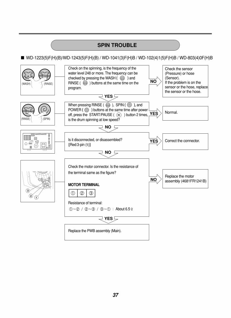
SPIN TROUBLE
Check the sensor(Pressure) or hose(Sensor). If the problem is on thesensor or the hose, replacethe sensor or the hose.
Normal.
Correct the connector.
Replace the motorassembly (4681FR1241B)
Check on the spinning, is the frequency of thewater level 248 or more. The frequency can be checked by pressing the WASH ( ) and RINSE ( ) buttons at the same time on theprogram.
When pressing RINSE ( ), SPIN ( ), andPOWER ( ) buttons at the same time after poweroff, press the START/PAUSE ( ) button 2 times,is the drum spinning at low speed?
Is it disconnected, or disassembled?~Red:3-pin (1)₩
Check the motor connector. Is the resistance of
the terminal same as the figure?
MOTOR TERMINAL
Resistance of terminal:
①~② / ②~③ / ③~① : About 6.5Ω
Replace the PWB assembly (Main).
① ② ③

38
WD-803(4)0(W)(F)(H)/WD-102(4)1(5)W(F)(H)/WD-1042F(H)
Rinse Spin
3
2
1
1
10
1 2 3 4 5 6 7 8 9 10
5
4
YES
YES
NO
NO
NO
YES
Check the sensor(Pressure) or hose(Sensor). If the problem is on thesensor or the hose, replacethe sensor or the hose.
Reconnect or repair it.
Replace the motorassembly.(4681FR1194A)
Press [Power]button with both [Rinse]and [Spin]buttons pressed after power off. Press [Start/Pause]button 2 times. Does the drum rotate at low spinspeed?
Is it disconnected or badly contacted?~Natural:3-pin (①), Red:4-pin (②), Blue:2-pin (③),
Yellow:2-pin (④)₩
Check the motor connector, is the resistance between
the terminal in figure the same as below?
Resistance between terminals
①~⑤:0.5~1.0Ω
⑤~⑩:1.5~2.5Ω
Be sure to unplug the machine before measuring.
MOTOR TERMINAL
Replace the PWB assembly (Main).

39
Disassemble and repair the parts after pulling out power cord from the outlet
10. DISASSEMBLY INSTRUCTIONS
① The PWB assembly (Display) connectors are
disconnected.
② Pull out drawer, three screws are unscrewed.
③ Push two upper hooks and pull the control panel
forward.
Hook Hook
CONTROL PANEL
PLATE ASSEMBLY (TOP)
PANEL ASSEMBLY (CONTROL)
PWB ASSEMBLY(DISPLAY)
① Two screws are unscrewed on the top plate.
② The plate assembly (Top) is pulled back and then
upward to arrow direction.
① The PWB assembly (Display) is disconnected.
② When 9 screws are unscrewed on the PWB
insulator and the PWB assembly (Display) is
disassembled from the PWB insulator.

40
① The hose clamps and the hose are disassembled.
② The ventilation bellows and the water inlet
bellows are disassembled on the tub.
DISPENSER ASSEMBLY
Valve (Hot)
DRAWERDRAWER
① Disassemble the top plate assembly.
② Pull the drawer to arrow direction.
③ Two screws are unscrewed.

41
① Disconnect the wiring connector.
② Unscrew 2 screws from the back.
When reconnecting the connector
~WD-1223FH(B)/1225FH(B)/1243FH(B)
WD-1245FH(B)/1041(3)FH(B)
WD-803(4)0(W)(F)H
WD-102(4)1(5)W(F)H/102(4)1(5)FH(B)
WD-1042FH(B)/803(4)0FH(B)₩
① The back cover is removed.
② Unscrew 2 screws
③ Pull the PWB assembly (Main) as shown.
12
3
INLET VALVE
PWB ASSEMBLY (MAIN)
VALVE#1 (MAIN) White/Black - Black
VALVE#2 (PRE) Gray/ White - Black
VALVE#3 (HOT) Blue/Red-Black
WD-1223(5)F(H)(B) / WD-1243(5)F(H)(B) WD-1041(3)F(H)B / WD-102(4)1(5)F(H)BWD-803(4)0F(H)B
WD-803(4)0(W)(F)(H)/WD-102(4)1(5)W(F)(H)WD-1042F(H)
42
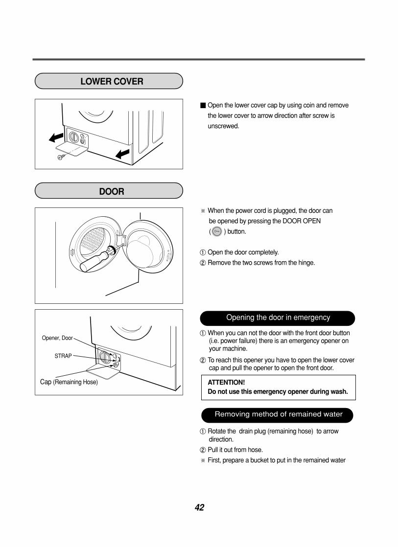
Open the lower cover cap by using coin and remove
the lower cover to arrow direction after screw is
unscrewed.
※ When the power cord is plugged, the door can
be opened by pressing the DOOR OPEN
( ) button.
① Open the door completely.
② Remove the two screws from the hinge.
① When you can not the door with the front door button (i.e. power failure) there is an emergency opener on your machine.
② To reach this opener you have to open the lower covercap and pull the opener to open the front door.
① Rotate the drain plug (remaining hose) to arrowdirection.
② Pull it out from hose.
※ First, prepare a bucket to put in the remained water
Opener, Door
STRAP
Cap (Remaining Hose)
LOWER COVER
DOOR
Opening the door in emergency
Removing method of remained water
ATTENTION!Do not use this emergency opener during wash.

43
① The cabinet gasket clamp is released.
② Two screws are unscrewed from the cabinet cover.
① Three screws are unscrewed from the lower cover.
② The lower cover is disassembled.
① The control panel is removed.
② Screw is unscrewed from the cabinet cover.
① Take apart the tub gasket clamp
② Make sure that the drain hole of the gasket is put
beneath when reassembling the gasket.
※Refer to the arrow mark on the tub cover.
GASKET ASSEMBLY

44
① The back cover is removed.
② The belt is pulled off while turning over the pulley.
③ The bolt is unscrewed to the shaft and then
the pulley pulled off.
① Two screws are unscrewed from the bracket (Motor).
② The motor is pushed to arrow direction and then
it is disassembled.
(When mounting the bushing should be fit the
bracket holder <Motor>)
① Lay the washing machine.
② The hinge (Damper) at the tub is pulled off
pressing on the snaps at the sharp end.
③ The hinge at the base is pulled off.
12
3
Hinge,Damper
Damper
PULLEY, MOTOR, DAMPER
(PULLEY)
(MOTOR)
(DAMPER)

45
Pump Outlet Hose
Tub Pump Hose
① Remove the pump outlet hose.
② Remove the tub pump hose.
③ The pump connectors are disconnected, the hose is
pulled off.
④ Three screws are unscrewed.
⑤ The pump is disassembled to arrow direction.
① Three screws are unscrewed.
② The heater M6 bolt is loosened and it is
released through the tub cover.
When mounting the heater, the heater should be
inserted the heater clip on the bottom of the tub.
① Pull it out by holding the thermistor bracket.
If holding the wire and pulling out it, it may be broken.
The thermistor should be checked it is pulled
to the rubber tightly.
PUMP
HEATER
THERMISTOR
CAUTION

46
DOOR HINGE ASSEMBLY
SWITCH ASSEMBLY, DOOR LOCK
WHEN FOREIGN MATERIAL STACK BETWEEN DRUM AND TUB
① Two screw are unscrewed on the door and the
door is disassembled.
② The cabinet cover clamp is removed and the
gasket is released.
③ Two screws are unscrewed on the door hinge.
④ The door hinge is disassembled by pressing
the door hinge arm inside the cabinet cover.
① The cabinet cover clamp is removed and
the gasket is released.
② Two screws are unscrewed.
③ The door lock S/W is disconnected from the
wiring connector and the strap.
① The heater is removed.
② The foreign material (wire, coin, etc) is removed
by inserting the long bar in the hole.
47
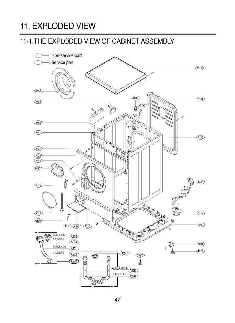
11-1.THE EXPLODED VIEW OF CABINET ASSEMBLY
11. EXPLODED VIEW
A110
A101
A100
A430
A104
A102
A410
A200
A201
A220
A310 A300A303
A133
A132
A140
A130
A131
A141
A450
A460
A150
: Non-service part
: Service part
A273
A274
A271
A272
A270
HOT(ORANGE)
COLD(BLUE)
HOT(ORANGE)
COLD(BLUE)
A275
A276
A277
HOT(ORANGE)
COLD(BLUE)
A440
A301

48
11-2 THE EXPLODED VIEW OF CONTROL PANEL & DISPENSER ASSEMBLY
F160
F431
F170
F432
F120
F220
F130
F300
F430
F440
F310
F110
F210
: Non-service part
: Service part

49
11-3 THE EXPLODED VIEW OF DRUM & TUB ASSEMBLY
K221
K210
K220
K121
K100
K104
K105
K410
K150
K610
K343
K550
K540K520K531K344 K340
K320
K310
K510
K141
K142
K110
K420
K411
K103
K135
K136
K101K131
K130
K131
K144
K140
K611
K102 K122
K530
K332
K330
: Non-service part: Service part
F140
K125


![WASHING MACHINE SERVICE MANUAL - Dryerdryernotheating.net/wp-content/uploads/2013/07/WM3431-LG-Compact... · WASHING MACHINE SERVICE MANUAL ... [For CANADA] ... The washer must be](https://img.pdfslide.us/doc/110x75/5ae3a1717f8b9ae74a8dfbe1/washing-machine-service-manual-machine-service-manual-for-canada-the.jpg)