Embed Size (px)
Citation preview
WASHING MACHINESERVICE MANUAL READ THIS MANUAL CAREFULLY TO DIAGNOSE TROUBLE CORRECTLY BEFORE OFFERING SERVICE.
website : http://www.LGEservice.come-mail : http://LGEservice.com/techsup.html
MODEL : WD(M)-80150FB
WD(M)-90150(5)FB
WD(M)-10150(5)FB/WD-10160(5)FB/WD-10164FB
WD(M)-11150(5)FB/WD-11151(6)FB/DWD-11151(6)FB/NWD-11151(6)FB
WD(M)-12150(5)FB/WD-12160(5)FB/WD-12164FB
WD(M)-13150(5)FB/WD-13151(6)FB/DWD-13151(6)FB/NWD-13151(6)FB
WD-1025FB/WD-10150(5)F
CAUTION

Jul. 2002 PRINTED IN KOREA P/No.:3828ER3013D
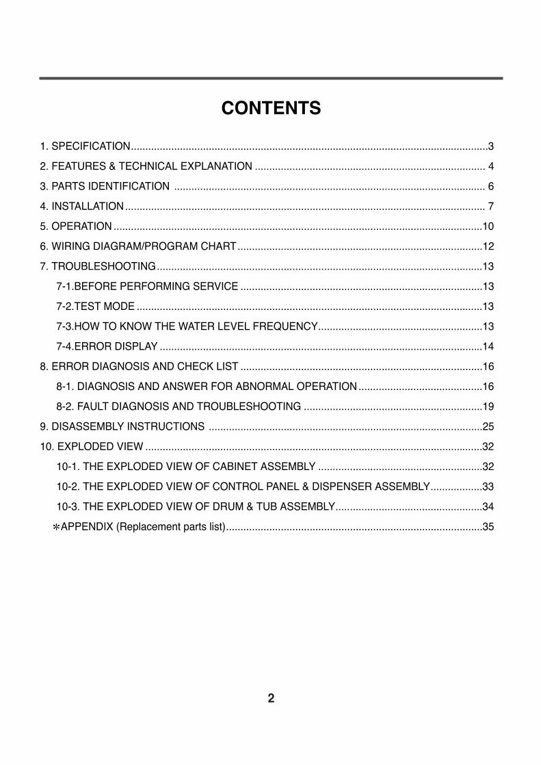
CONTENTS
1. SPECIFICATION............................................................................................................................3
2. FEATURES & TECHNICAL EXPLANATION ................................................................................ 4
3. PARTS IDENTIFICATION ............................................................................................................ 6
4. INSTALLATION............................................................................................................................. 7
5. OPERATION ................................................................................................................................10
6. WIRING DIAGRAM/PROGRAM CHART.....................................................................................12
7. TROUBLESHOOTING.................................................................................................................13
7-1.BEFORE PERFORMING SERVICE ....................................................................................13
7-2.TEST MODE ........................................................................................................................13
7-3.HOW TO KNOW THE WATER LEVEL FREQUENCY.........................................................13
7-4.ERROR DISPLAY ................................................................................................................14
8. ERROR DIAGNOSIS AND CHECK LIST ....................................................................................16
8-1. DIAGNOSIS AND ANSWER FOR ABNORMAL OPERATION ...........................................16
8-2. FAULT DIAGNOSIS AND TROUBLESHOOTING ..............................................................19
9. DISASSEMBLY INSTRUCTIONS ...............................................................................................25
10. EXPLODED VIEW .....................................................................................................................32
10-1. THE EXPLODED VIEW OF CABINET ASSEMBLY .........................................................32
10-2. THE EXPLODED VIEW OF CONTROL PANEL & DISPENSER ASSEMBLY..................33
10-3. THE EXPLODED VIEW OF DRUM & TUB ASSEMBLY...................................................34
APPENDIX (Replacement parts list).........................................................................................35
2
3
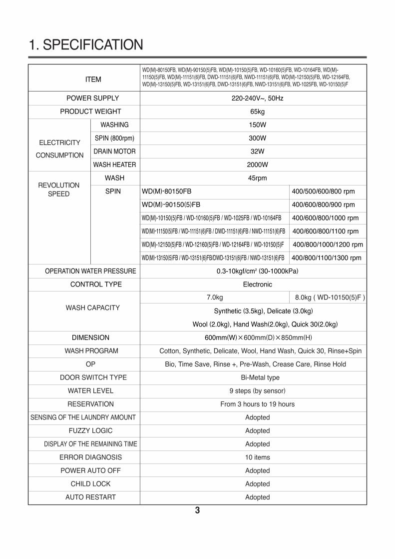
1. SPECIFICATION
ITEM
POWER SUPPLY 220-240V~, 50Hz
PRODUCT WEIGHT 65kg
WASHING 150W
SPIN (800rpm) 300W
DRAIN MOTOR 32W
WASH HEATER 2000W
WASH 45rpm
SPIN WD(M)-80150FB 400/500/600/800 rpm
WD(M)-90150(5)FB 400/600/800/900 rpm
WD(M)-10150(5)FB / WD-10160(5)FB / WD-1025FB / WD-10164FB 400/600/800/1000 rpm
WD(M)-11150(5)FB / WD-11151(6)FB / DWD-11151(6)FB / NWD-11151(6)FB 400/600/800/1100 rpm
WD(M)-12150(5)FB / WD-12160(5)FB / WD-12164FB / WD-10150(5)F 400/800/1000/1200 rpm
WD(M)-13150(5)FB / WD-13151(6)FB/DWD-13151(6)FB / NWD-13151(6)FB 400/800/1100/1300 rpm
OPERATION WATER PRESSURE 0.3-10kgf/cm2 (30-1000kPa)
CONTROL TYPE Electronic
Synthetic (3.5kg), Delicate (3.0kg)
Wool (2.0kg), Hand Wash(2.0kg), Quick 30(2.0kg)
DIMENSION 600mm(W)×600mm(D)×850mm(H)
WASH PROGRAM Cotton, Synthetic, Delicate, Wool, Hand Wash, Quick 30, Rinse+Spin
OP Bio, Time Save, Rinse +, Pre-Wash, Crease Care, Rinse Hold
DOOR SWITCH TYPE Bi-Metal type
WATER LEVEL 9 steps (by sensor)
RESERVATION From 3 hours to 19 hours
SENSING OF THE LAUNDRY AMOUNT Adopted
FUZZY LOGIC Adopted
DISPLAY OF THE REMAINING TIME Adopted
ERROR DIAGNOSIS 10 items
POWER AUTO OFF Adopted
CHILD LOCK Adopted
AUTO RESTART Adopted
ELECTRICITY
CONSUMPTION
REVOLUTION SPEED
WASH CAPACITY
WD(M)-80150FB, WD(M)-90150(5)FB, WD(M)-10150(5)FB, WD-10160(5)FB, WD-10164FB, WD(M)-11150(5)FB, WD(M)-11151(6)FB, DWD-11151(6)FB, NWD-11151(6)FB, WD(M)-12150(5)FB, WD-12164FB,WD(M)-13150(5)FB, WD-13151(6)FB, DWD-13151(6)FB, NWD-13151(6)FB, WD-1025FB, WD-10150(5)F
8.0kg ( WD-10150(5)F )7.0kg
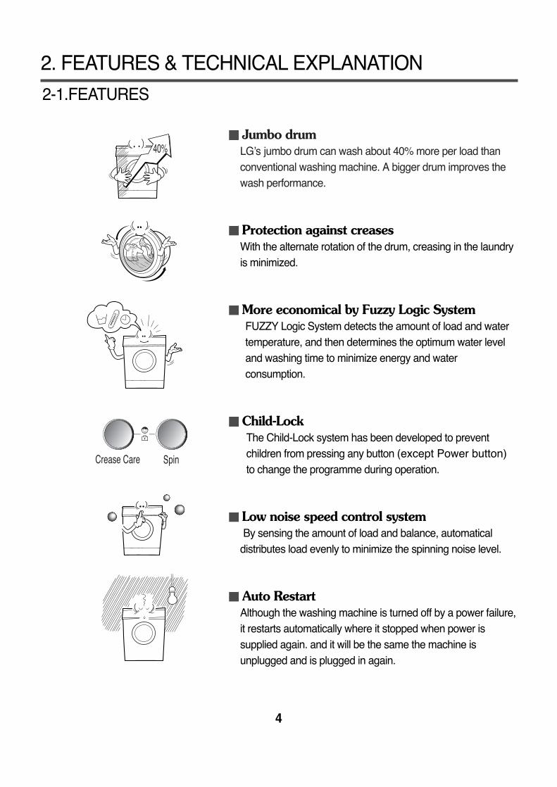
Jumbo drumLG’s jumbo drum can wash about 40% more per load thanconventional washing machine. A bigger drum improves thewash performance.
Protection against creasesWith the alternate rotation of the drum, creasing in the laundryis minimized.
More economical by Fuzzy Logic SystemFUZZY Logic System detects the amount of load and watertemperature, and then determines the optimum water leveland washing time to minimize energy and waterconsumption.
Child-LockThe Child-Lock system has been developed to preventchildren from pressing any button (except Power button)to change the programme during operation.
Low noise speed control systemBy sensing the amount of load and balance, automatical
distributes load evenly to minimize the spinning noise level.
Auto RestartAlthough the washing machine is turned off by a power failure,it restarts automatically where it stopped when power issupplied again. and it will be the same the machine isunplugged and is plugged in again.
2. FEATURES & TECHNICAL EXPLANATION
4
2-1.FEATURES
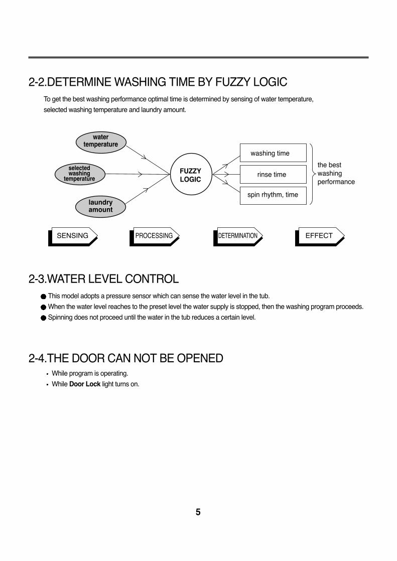
2-2.DETERMINE WASHING TIME BY FUZZY LOGICTo get the best washing performance optimal time is determined by sensing of water temperature,
selected washing temperature and laundry amount.
2-3.WATER LEVEL CONTROLThis model adopts a pressure sensor which can sense the water level in the tub.
When the water level reaches to the preset level the water supply is stopped, then the washing program proceeds.
Spinning does not proceed until the water in the tub reduces a certain level.
2-4.THE DOOR CAN NOT BE OPENEDWhile program is operating.
While Door Lock light turns on.
5
FUZZYLOGIC
laundryamount
selectedwashing
temperature
watertemperature
washing time
rinse time
spin rhythm, time
the bestwashingperformance
SENSING PROCESSING DETERMINATION EFFECT
3. PARTS IDENTIFICATION
6
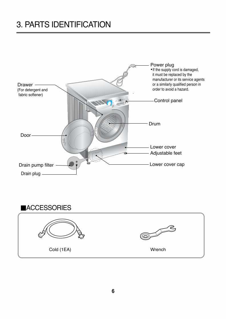
Cold (1EA) Wrench
Power plug
Control panel
Door
Lower coverAdjustable feet
(For detergent and fabric softener)
Drawer
Drum
Lower cover cap
Drain plug
If the supply cord is damaged, it must be replaced by the
manufacturer or its service agents or a similarly qualified person in order to avoid a hazard.
Drain pump filter
Time Sime SaveCrease Cease Carare
ACCESSORIES
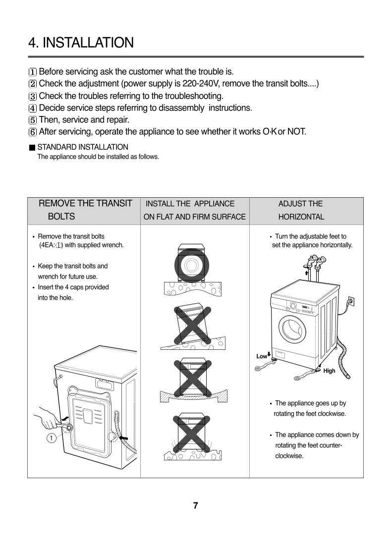
Before servicing ask the customer what the trouble is.Check the adjustment (power supply is 220-240V, remove the transit bolts....)Check the troubles referring to the troubleshooting.Decide service steps referring to disassembly instructions.Then, service and repair.After servicing, operate the appliance to see whether it works O Kor NOT.
STANDARD INSTALLATIONThe appliance should be installed as follows.
REMOVE THE TRANSIT INSTALL THE APPLIANCE ADJUST THE
BOLTS ON FLAT AND FIRM SURFACE HORIZONTAL
Remove the transit bolts Turn the adjustable feet to(4EA: ) with supplied wrench. set the appliance horizontally.
Keep the transit bolts and
wrench for future use.
Insert the 4 caps provided
into the hole.
The appliance goes up by
rotating the feet clockwise.
The appliance comes down by
rotating the feet counter-
clockwise.
4. INSTALLATION
7
1
High
Low
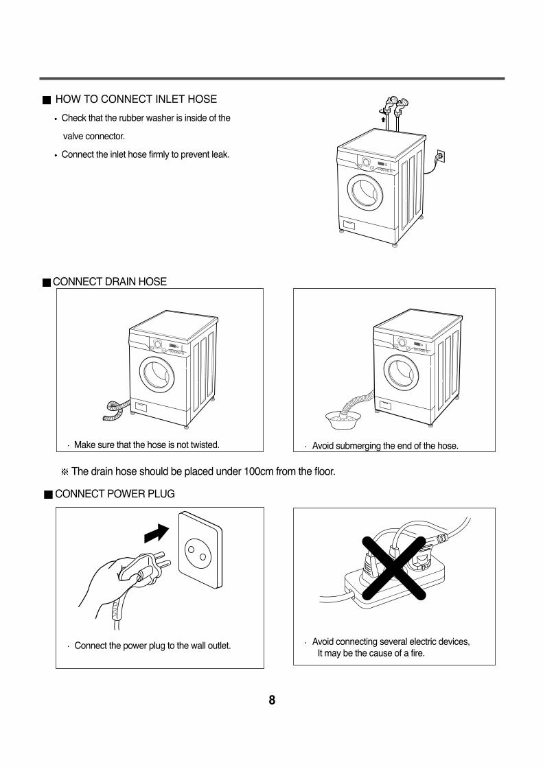
HOW TO CONNECT INLET HOSE
Check that the rubber washer is inside of the
valve connector.
Connect the inlet hose firmly to prevent leak.
CONNECT DRAIN HOSE
CONNECT POWER PLUG
8
Make sure that the hose is not twisted.
The drain hose should be placed under 100cm from the floor.
Connect the power plug to the wall outlet. Avoid connecting several electric devices, It may be the cause of a fire.
Avoid submerging the end of the hose.
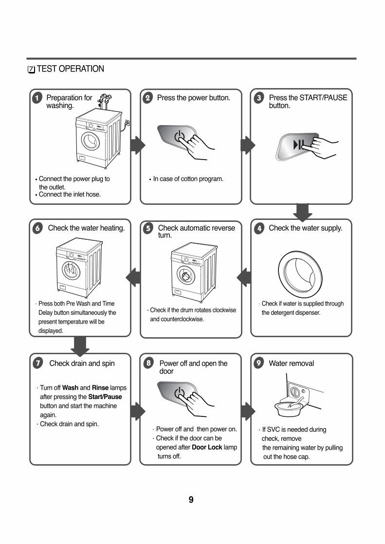
TEST OPERATION
9
Connect the power plug to In case of cotton program. the outlet.Connect the inlet hose.
Preparation for Press the power button. Press the START/PAUSEwashing. button.
Press both Pre Wash and TimeDelay button simultaneously thepresent temperature will bedisplayed.
Check if the drum rotates clockwiseand counterclockwise.
Check if water is supplied throughthe detergent dispenser.
Power off and then power on.Check if the door can be opened after Door Lock lampturns off.
Turn off Wash and Rinse lampsafter pressing the Start/Pausebutton and start the machineagain.Check drain and spin.
If SVC is needed during check, removethe remaining water by pulling out the hose cap.
Check the water heating. Check automatic reverse Check the water supply.turn.
Check drain and spin Power off and open the Water removal door
10
5. OPERATION
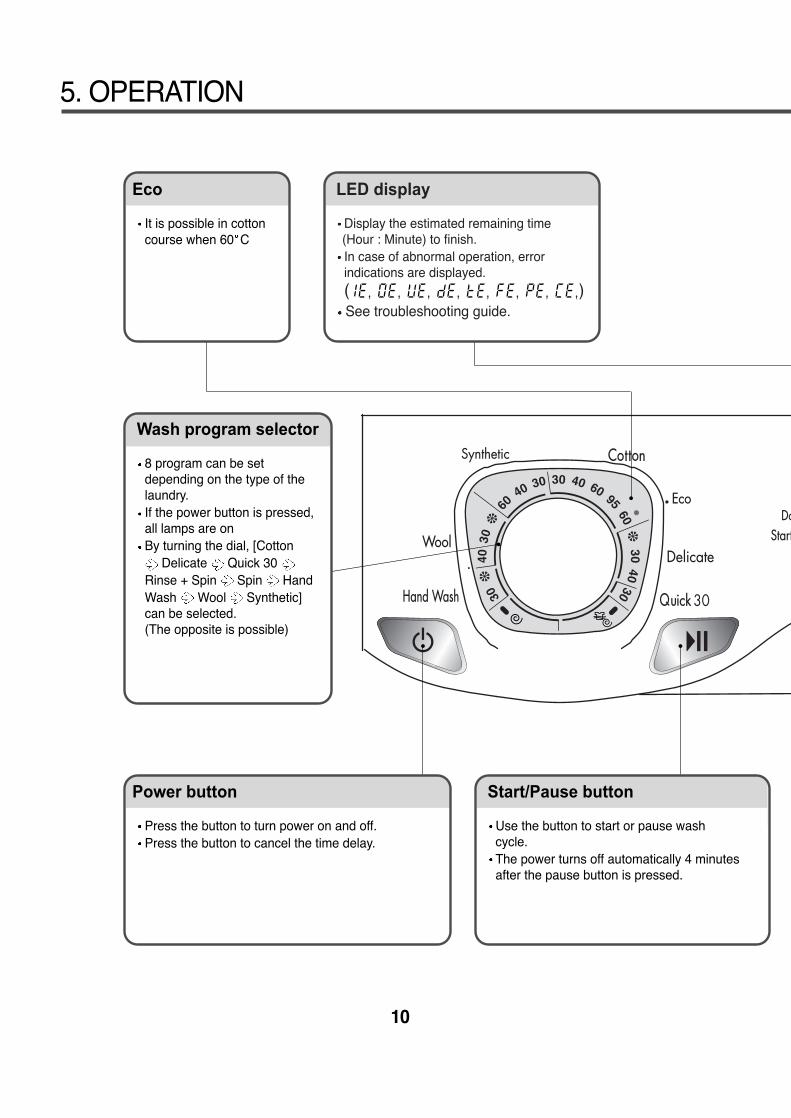
LED display
Display the estimated remaining time(Hour : Minute) to finish.In case of abnormal operation, errorindications are displayed. ( )See troubleshooting guide.
Eco
It is possible in cottoncourse when 60 C
Power button
Press the button to turn power on and off.Press the button to cancel the time delay.
Start/Pause button
Use the button to start or pause washcycle.The power turns off automatically 4 minutesafter the pause button is pressed.
Wash program selector
8 program can be setdepending on the type of thelaundry.If the power button is pressed,all lamps are onBy turning the dial, [Cotton
Delicate Quick 30 Rinse + Spin Spin HandWash Wool Synthetic]can be selected.(The opposite is possible)
11
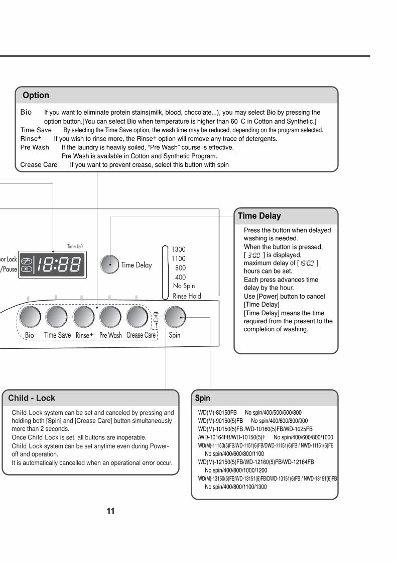
Child - Lock
Child Lock system can be set and canceled by pressing andholding both [Spin] and [Crease Care] button simultaneouslymore than 2 seconds.Once Child Lock is set, all buttons are inoperable.Child Lock system can be set anytime even during Power-off and operation.It is automatically cancelled when an operational error occur.
Spin
WD(M)-80150FB No spin/400/500/600/800WD(M)-90150(5)FB No spin/400/600/800/900WD(M)-10150(5)FB /WD-10160(5)FB/WD-1025FB/WD-10164FB/WD-10150(5)F No spin/400/600/800/1000WD(M)-11150(5)FB/WD-1151(6)FB/DWD-11151(6)FB / NWD-11151(6)FB
No spin/400/600/800/1100WD(M)-12150(5)FB/WD-12160(5)FB/WD-12164FB
No spin/400/800/1000/1200WD(M)-13150(5)FB/WD-13151(6)FB/DWD-13151(6)FB / NWD-13151(6)FB
No spin/400/800/1100/1300
Time Delay
Press the button when delayedwashing is needed.When the button is pressed,[ ] is displayed, maximum delay of [ ]hours can be set.Each press advances timedelay by the hour.Use [Power] button to cancel[Time Delay][Time Delay] means the timerequired from the present to thecompletion of washing.
Option
Bio : If you want to eliminate protein stains(milk, blood, chocolate...), you may select Bio by pressing theoption button.[You can select Bio when temperature is higher than 60。C in Cotton and Synthetic.]
Time Save : By selecting the Time Save option, the wash time may be reduced, depending on the program selected.Rinse+ : If you wish to rinse more, the Rinse+ option will remove any trace of detergents.Pre Wash : If the laundry is heavily soiled, “Pre Wash” course is effective.
Pre Wash is available in Cotton and Synthetic Program.Crease Care : If you want to prevent crease, select this button with spin
12
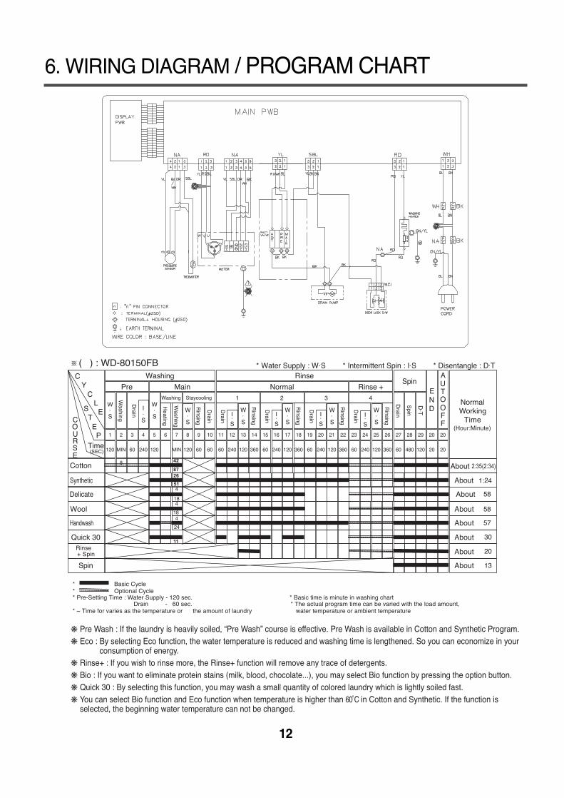
6. WIRING DIAGRAM / PROGRAM CHART
42
8726
51
11
58
58
57
2:35(2:34)
❋ Pre Wash : If the laundry is heavily soiled, “Pre Wash” course is effective. Pre Wash is available in Cotton and Synthetic Program.❋ Eco : By selecting Eco function, the water temperature is reduced and washing time is lengthened. So you can economize in your
consumption of energy.❋ Rinse+ : If you wish to rinse more, the Rinse+ function will remove any trace of detergents.❋ Bio : If you want to eliminate protein stains (milk, blood, chocolate...), you may select Bio function by pressing the option button.❋ Quick 30 : By selecting this function, you may wash a small quantity of colored laundry which is lightly soiled fast.❋ You can select Bio function and Eco function when temperature is higher than 60˚C in Cotton and Synthetic. If the function is
selected, the beginning water temperature can not be changed.
※( ) : WD-80150FB
7-1.BEFORE PERFORMING SERVICE■ Be careful of electric shock or disconnecting the parts while trouble shooting.
■ Voltage of each terminal in 220-240V and DC while applying an electric current.
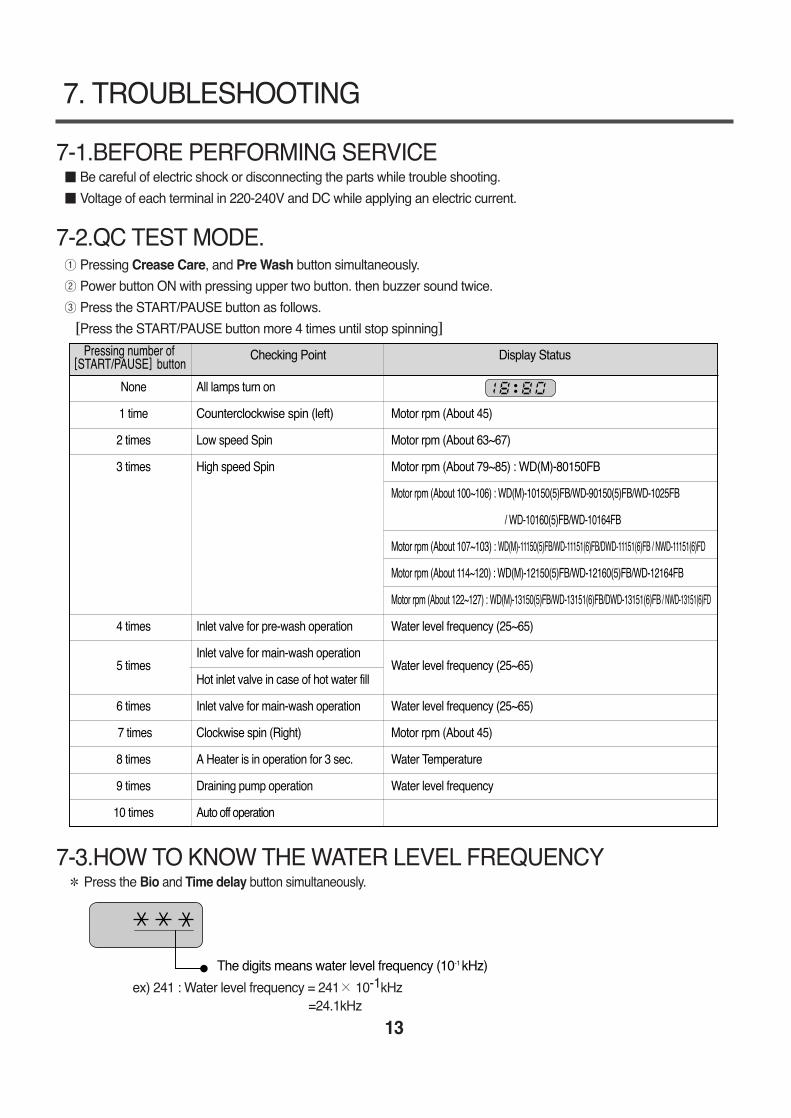
7-2.QC TEST MODE.① Pressing Crease Care, and Pre Wash button simultaneously.
② Power button ON with pressing upper two button. then buzzer sound twice.
③ Press the START/PAUSE button as follows.
~Press the START/PAUSE button more 4 times until stop spinning₩
7-3.HOW TO KNOW THE WATER LEVEL FREQUENCYPress the Bio and Time delay button simultaneously.
ex) 241 : Water level frequency = 241× 10-1kHz=24.1kHz
13
7. TROUBLESHOOTING
The digits means water level frequency (10-1 kHz)
Pressing number of[START/PAUSE]button
Checking Point Display Status
None All lamps turn on
1 time Counterclockwise spin (left) Motor rpm (About 45)
2 times Low speed Spin Motor rpm (About 63~67)
3 times High speed Spin Motor rpm (About 79~85) : WD(M)-80150FB
Motor rpm (About 100~106) : WD(M)-10150(5)FB/WD-90150(5)FB/WD-1025FB
/ WD-10160(5)FB/WD-10164FB
Motor rpm (About 107~103) : WD(M)-11150(5)FB/WD-11151(6)FB/DWD-11151(6)FB / NWD-11151(6)FD
Motor rpm (About 114~120) : WD(M)-12150(5)FB/WD-12160(5)FB/WD-12164FB
Motor rpm (About 122~127) : WD(M)-13150(5)FB/WD-13151(6)FB/DWD-13151(6)FB / NWD-13151(6)FD
4 times Inlet valve for pre-wash operation Water level frequency (25~65)
5 timesInlet valve for main-wash operation
Water level frequency (25~65)Hot inlet valve in case of hot water fill
6 times Inlet valve for main-wash operation Water level frequency (25~65)
7 times Clockwise spin (Right) Motor rpm (About 45)
8 times A Heater is in operation for 3 sec. Water Temperature
9 times Draining pump operation Water level frequency
10 times Auto off operation
14
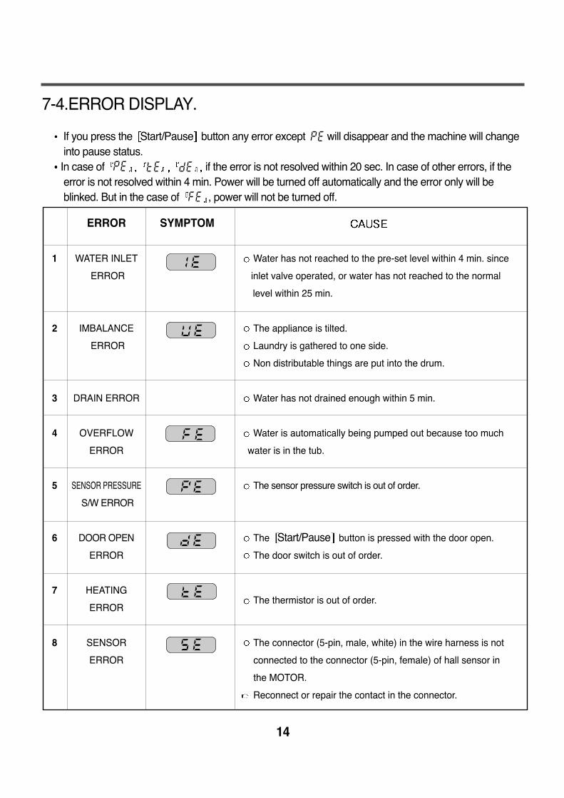
7-4.ERROR DISPLAY.
If you press the Start/Pause button any error except will disappear and the machine will changeinto pause status.In case of if the error is not resolved within 20 sec. In case of other errors, if theerror is not resolved within 4 min. Power will be turned off automatically and the error only will beblinked. But in the case of , power will not be turned off.
ERROR SYMPTOM
1 WATER INLET Water has not reached to the pre-set level within 4 min. since
ERROR inlet valve operated, or water has not reached to the normal
level within 25 min.
2 IMBALANCE The appliance is tilted.
ERROR Laundry is gathered to one side.
Non distributable things are put into the drum.
3 DRAIN ERROR Water has not drained enough within 5 min.
4 OVERFLOW Water is automatically being pumped out because too much
ERROR water is in the tub.
5 SENSOR PRESSURE The sensor pressure switch is out of order.
S/W ERROR
6 DOOR OPEN The Start/Pause button is pressed with the door open.
ERROR The door switch is out of order.
7 HEATING
ERRORThe thermistor is out of order.
8 SENSOR The connector (5-pin, male, white) in the wire harness is not
ERROR connected to the connector (5-pin, female) of hall sensor in
the MOTOR.
Reconnect or repair the contact in the connector.
15
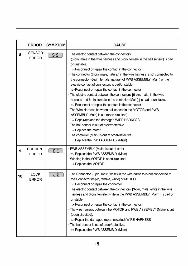
ERROR SYMPTOM CAUSE
8
9
10
• The electric contact between the connectors
(5-pin, male in the wire harness and 5-pin, female in the hall sensor) is bad
or unstable.
Reconnect or repair the contact in the connector
• The connector (6-pin, male, natural) in the wire harness is not connected to
the connector (6-pin, female, natural) of PWB ASSEMBLY (Main) or the
electric contact of connectors is bad/unstable.
Reconnect or repair the contact in the connector
• The electric contact between the connectors 6-pin, male, in the wire
harness and 6-pin, female in the controller (Main) is bad or unstable.
Reconnect or repair the contact in the connector
• The Wire Harness between hall sensor in the MOTOR and PWB
ASSEMBLY (Main) is cut (open circuited).
Repair/replace the damaged WIRE HARNESS
• The hall sensor is out of order/defective.
Replace the motor
• The controller (Main) is out of order/defective.
Replace the PWB ASSEMBLY (Main)
• PWB ASSEMBLY (Main) is out of order
Replace the PWB ASSEMBLY (Main)
• Winding in the MOTOR is short-circuited.
Replace the MOTOR
• The Connector (3-pin, male, white) in the wire harness is not connected to
the Connector (3-pin, female, white) of MOTOR.
Reconnect or repair the connector
• The electric contact between the connectors 3-pin, male, white in the wire
harness and 6-pin, female, white in the PWB ASSEMBLY (Main) is bad or
unstable.
Reconnect or repair the contact in the connector
• The wire harness between the MOTOR and PWB ASSEMBLY (Main) is cut
(open circuited).
Repair the damaged (open-circuited) WIRE HARNESS
• The hall sensor is out of order/defective.
Replace the PWB ASSEMBLY (Main)
SENSOR
ERROR
CURRENT
ERROR
LOCK
ERROR
16
8-1.DIAGNOSIS AND ANSWER FOR ABNORMAL OPERATION
8. ERROR DIAGNOSIS AND CHECK LIST
SYMPTOM GUIDE FOR SERVICE CALL
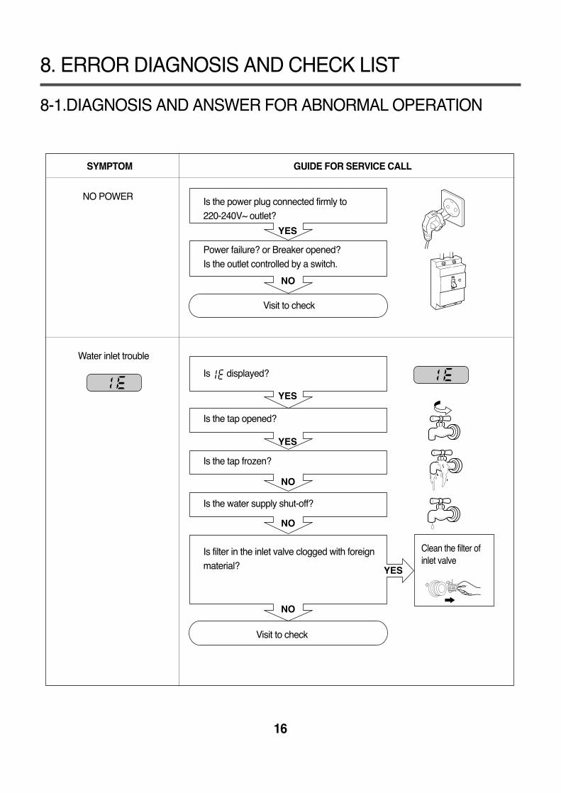
NO POWER
Water inlet trouble
YES
YES
YES
NO
NO
YES
NO
NO
Is the power plug connected firmly to 220-240V~ outlet?
Power failure? or Breaker opened?Is the outlet controlled by a switch.
Visit to check
Is displayed?
Is the tap opened?
Is the tap frozen?
Is the water supply shut-off?
Is filter in the inlet valve clogged with foreignmaterial?
Visit to check
Clean the filter ofinlet valve
17
SYMPTOM GUIDE FOR SERVICE CALL
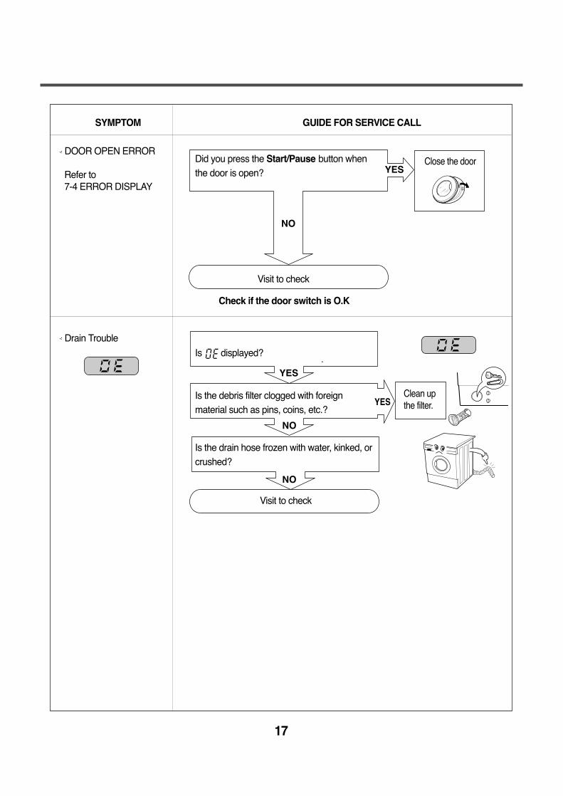
DOOR OPEN ERROR
Refer to 7-4 ERROR DISPLAY
Drain Trouble
NO
YES
YES
NO
NO
YES
Did you press the Start/Pause button whenthe door is open?
Visit to check
Check if the door switch is O.K
Is displayed?
Is the debris filter clogged with foreignmaterial such as pins, coins, etc.?
Is the drain hose frozen with water, kinked, orcrushed?
Visit to check
Close the door
Clean up the filter.
18
SYMPTOM GUIDE FOR SERVICE CALL
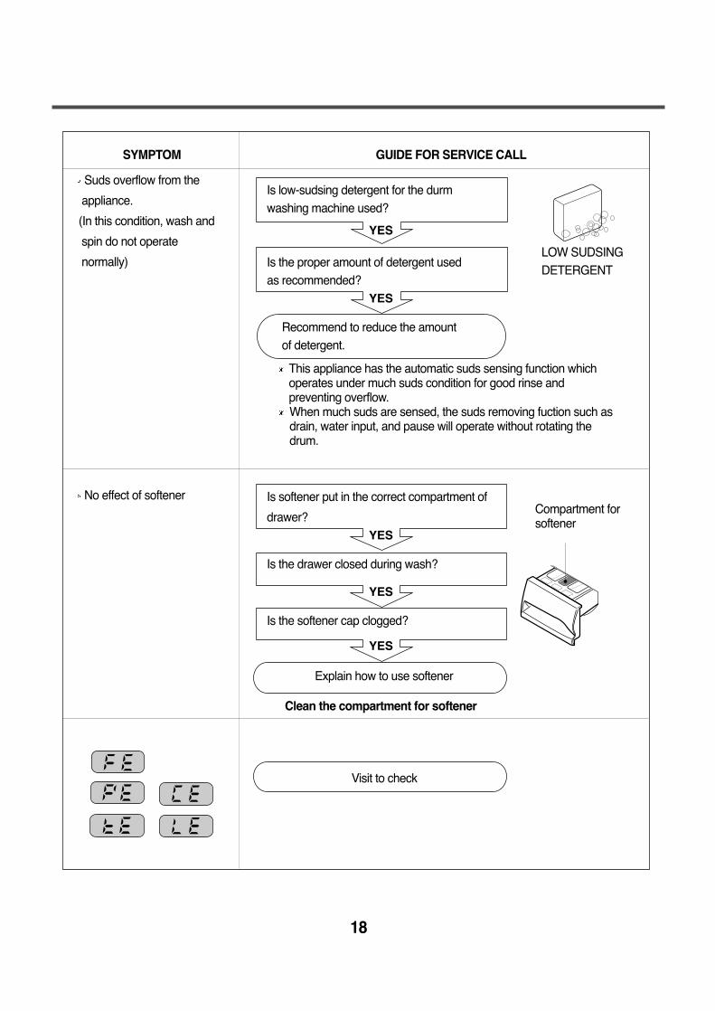
Suds overflow from the
appliance.
(In this condition, wash and
spin do not operate
normally)
No effect of softener
YES
YES
YES
YES
YES
Is low-sudsing detergent for the durmwashing machine used?
Is the proper amount of detergent used as recommended?
Recommend to reduce the amount of detergent.
Is softener put in the correct compartment of
drawer?
Is the drawer closed during wash?
Is the softener cap clogged?
Explain how to use softener
Clean the compartment for softener
Visit to check
LOW SUDSINGDETERGENT
Compartment forsoftener
This appliance has the automatic suds sensing function whichoperates under much suds condition for good rinse andpreventing overflow.When much suds are sensed, the suds removing fuction such asdrain, water input, and pause will operate without rotating thedrum.
19
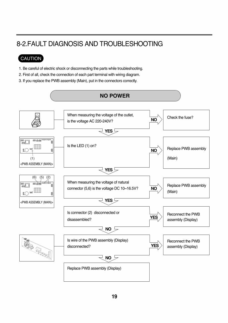
8-2.FAULT DIAGNOSIS AND TROUBLESHOOTING
1. Be careful of electric shock or disconnecting the parts while troubleshooting.
2. First of all, check the connection of each part terminal with wiring diagram.
3. If you replace the PWB assembly (Main), put in the connectors correctly.
CAUTION
NO
NO
NO
YES
YES
YES
YES
NO
NO
YES
<PWB ASSEMBLY (MAIN)>
<PWB ASSEMBLY (MAIN)>
(1)
(6) (5) (2)
Check the fuse?
Replace PWB assembly
(Main)
Replace PWB assembly
(Main)
Reconnect the PWBassembly (Display)
Reconnect the PWBassembly (Display)
When measuring the voltage of the outlet,
is the voltage AC 220-240V?
Is the LED (1) on?
When measuring the voltage of natural
connector (5,6) is the voltage DC 10~16.5V?
Is connector (2) disconnected or
disassembled?
Is wire of the PWB assembly (Display)
disconnected?
Replace PWB assembly (Display)
NO POWER
20
NO
YES
NO
NO
YES
NO
YES
YES
NO
NO
YES
YES
YES
NO
NO
NO
YES
Wiring diagram
option (HOT)
option (HOT)
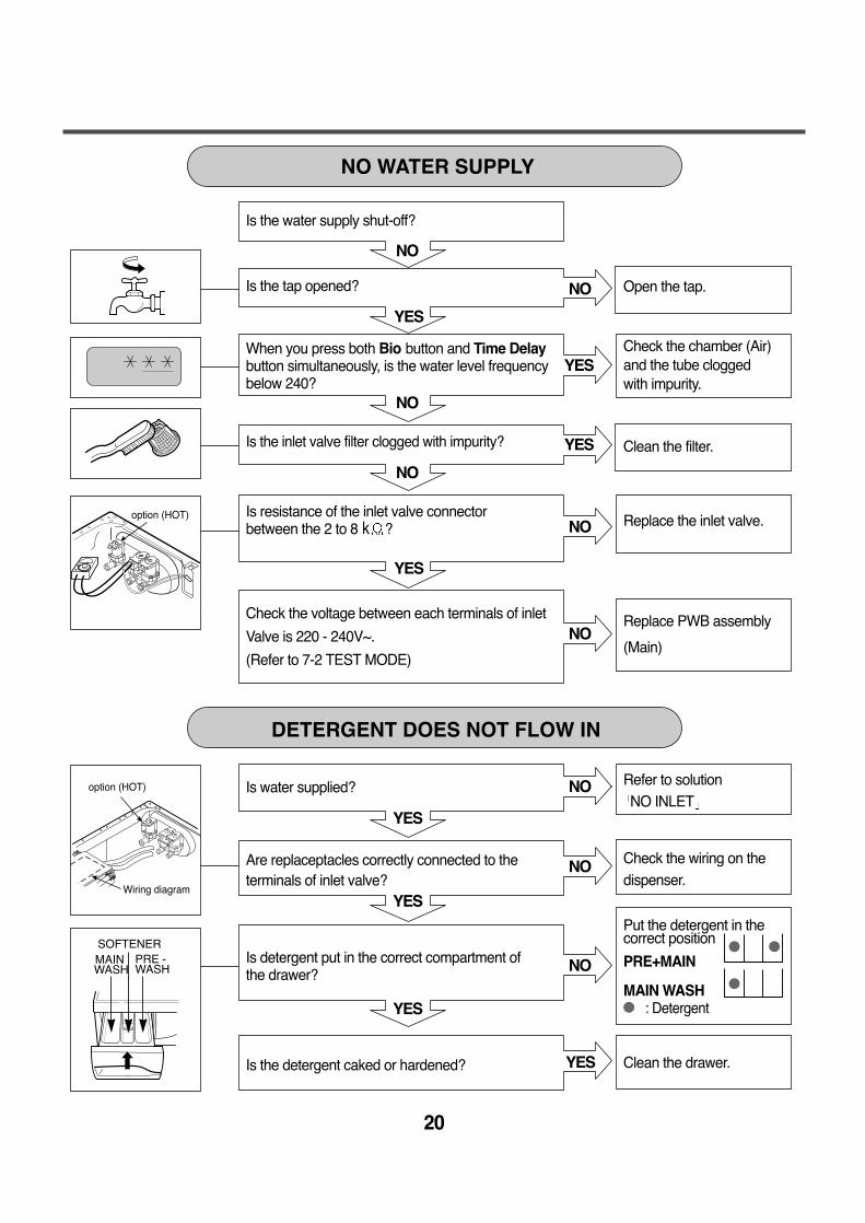
Is the water supply shut-off?
Is the tap opened?
When you press both Bio button and Time Delaybutton simultaneously, is the water level frequencybelow 240?
Is the inlet valve filter clogged with impurity?
Is resistance of the inlet valve connector between the 2 to 8 k ?
Check the voltage between each terminals of inlet
Valve is 220 - 240V~.
(Refer to 7-2 TEST MODE)
Is water supplied?
Are replaceptacles correctly connected to theterminals of inlet valve?
Is detergent put in the correct compartment ofthe drawer?
Is the detergent caked or hardened?
Open the tap.
Check the chamber (Air)and the tube clogged with impurity.
Clean the filter.
Replace the inlet valve.
Replace PWB assembly
(Main)
Refer to solutionNO INLET
Check the wiring on thedispenser.
Put the detergent in thecorrect position
PRE+MAIN
MAIN WASH: Detergent
Clean the drawer.
NO WATER SUPPLY
DETERGENT DOES NOT FLOW IN
MAINWASH
SOFTENERPRE -WASH
21
YES
YES
YES
NO
NO
NO
NO
NO
YES
YES
YES
YES
Wiring diagram
option (HOT)
ABNORMAL SOUND
SOFTENER DOES NOT FLOW IN
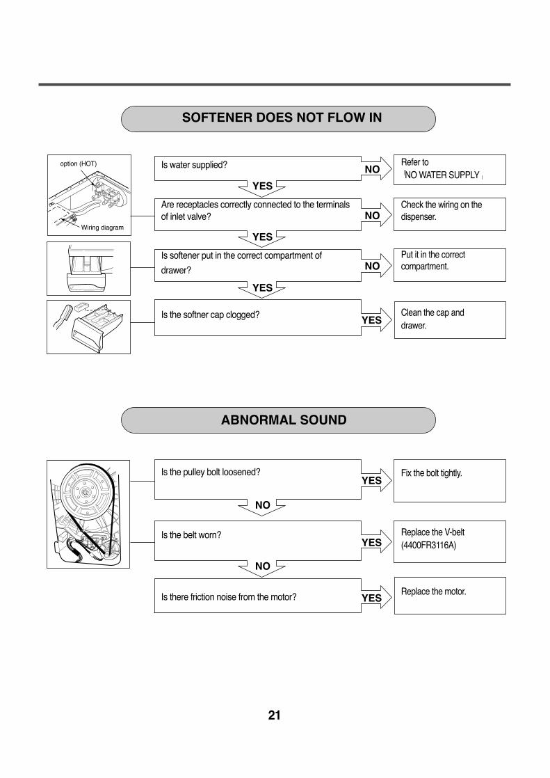
Fix the bolt tightly.
Replace the V-belt(4400FR3116A)
Replace the motor.
Refer toNO WATER SUPPLY
Check the wiring on the dispenser.
Put it in the correctcompartment.
Clean the cap anddrawer.
Is the pulley bolt loosened?
Is the belt worn?
Is there friction noise from the motor?
Is water supplied?
Are receptacles correctly connected to the terminalsof inlet valve?
Is softener put in the correct compartment of
drawer?
Is the softner cap clogged?
22
AC 220-240V
NO
NO
YES
YES
YES
NO
NO
NO
NO
YES
YES
NO2
1
PWB ASSEMBLY (MAIN)
PWB ASSEMBLY (MAIN)
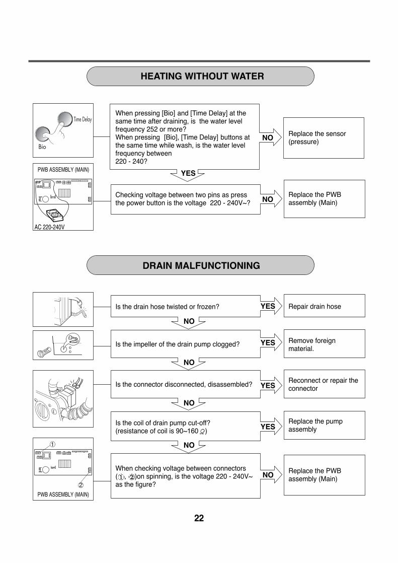
Replace the sensor (pressure)
Replace the PWBassembly (Main)
Repair drain hose
Remove foreignmaterial.
Reconnect or repair theconnector
Replace the pumpassembly
Replace the PWBassembly (Main)
When pressing [Bio] and [Time Delay] at thesame time after draining, is the water levelfrequency 252 or more? When pressing [Bio], [Time Delay] buttons atthe same time while wash, is the water levelfrequency between 220 - 240?
Checking voltage between two pins as pressthe power button is the voltage 220 - 240V~?
Is the drain hose twisted or frozen?
Is the impeller of the drain pump clogged?
Is the connector disconnected, disassembled?
Is the coil of drain pump cut-off?(resistance of coil is 90~160 )
When checking voltage between connectors( , )on spinning, is the voltage 220 - 240V~ as the figure?
HEATING WITHOUT WATER
DRAIN MALFUNCTIONING
23
NO
YES
YES
WASH HEATER TROUBLE
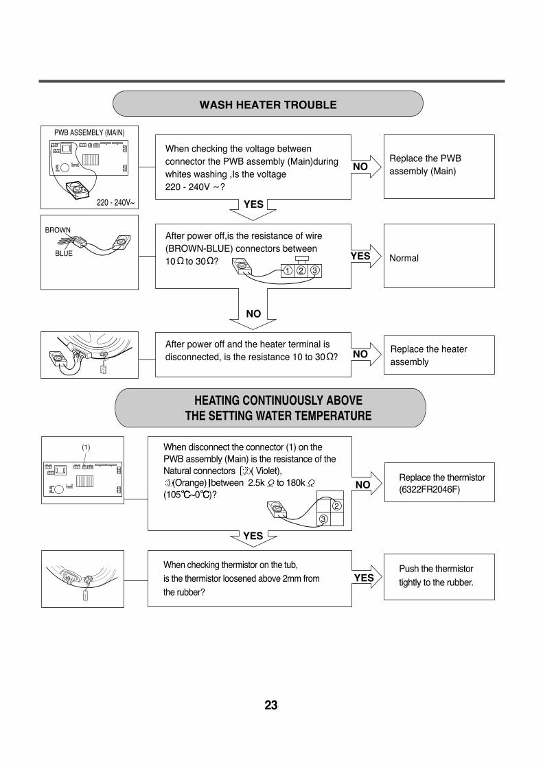
When checking the voltage between connector the PWB assembly (Main)during whites washing ,Is the voltage 220 - 240V ?
Replace the PWB assembly (Main)
YES
NO
After power off and the heater terminal isdisconnected, is the resistance 10 to 30 ?
Replace the heater assembly
NO
After power off,is the resistance of wire(BROWN-BLUE) connectors between10 to 30 ? Normal
NO
YES
BROWN
BLUE
2
3
1 2 3
~
220 - 240V~
(1)
PWB ASSEMBLY (MAIN)
Replace the thermistor(6322FR2046F)
Push the thermistortightly to the rubber.
When disconnect the connector (1) on the PWB assembly (Main) is the resistance of the Natural connectors ( Violet),
(Orange) between 2.5k to 180k(105 ~0 )?
When checking thermistor on the tub, is the thermistor loosened above 2mm from the rubber?
HEATING CONTINUOUSLY ABOVE THE SETTING WATER TEMPERATURE
24
3@
1@2
NO
YES
YES
YES
NO
NO
NO
YES
(1)
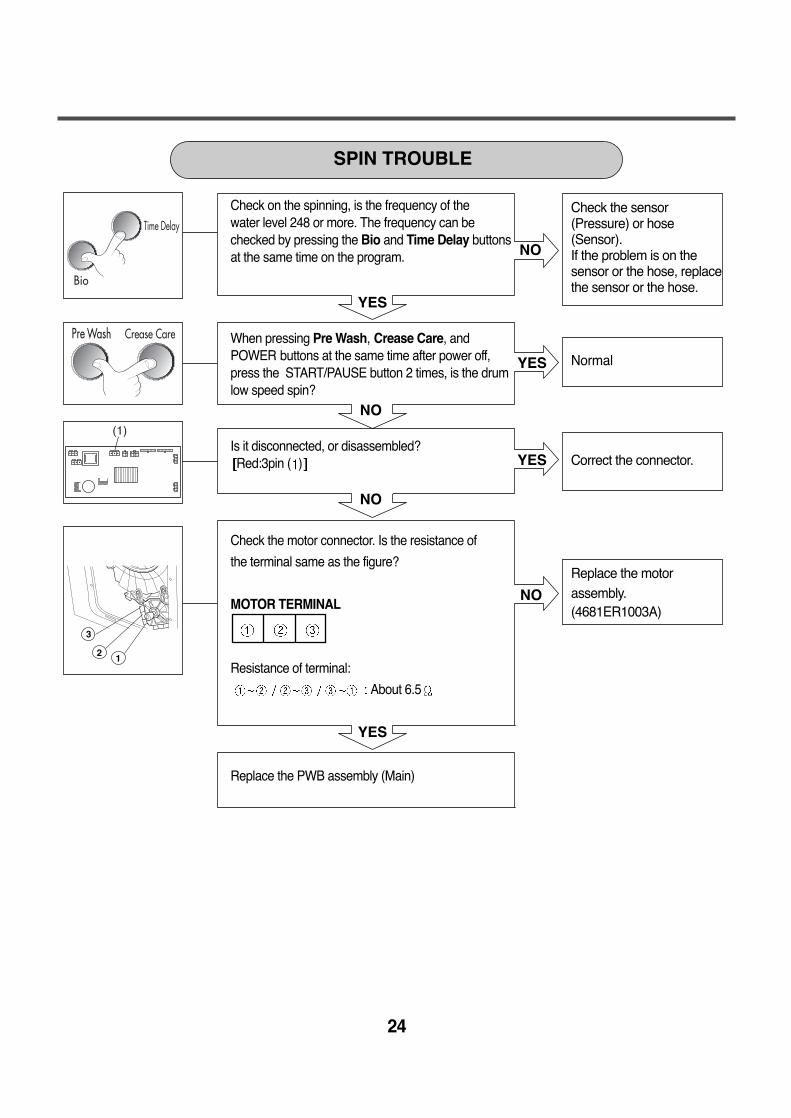
SPIN TROUBLE
Check the sensor(Pressure) or hose (Sensor). If the problem is on thesensor or the hose, replacethe sensor or the hose.
Normal
Correct the connector.
Replace the motorassembly.(4681ER1003A)
Check on the spinning, is the frequency of thewater level 248 or more. The frequency can be checked by pressing the Bio and Time Delay buttonsat the same time on the program.
When pressing Pre Wash, Crease Care, andPOWER buttons at the same time after power off,press the START/PAUSE button 2 times, is the drumlow speed spin?
Is it disconnected, or disassembled?Red:3pin ( )
Check the motor connector. Is the resistance of
the terminal same as the figure?
MOTOR TERMINAL
Resistance of terminal:
About 6.5
Replace the PWB assembly (Main)
25
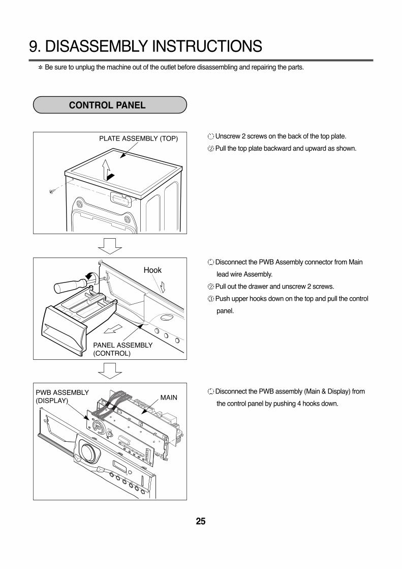
Be sure to unplug the machine out of the outlet before disassembling and repairing the parts.
9. DISASSEMBLY INSTRUCTIONS
Unscrew 2 screws on the back of the top plate.
Pull the top plate backward and upward as shown.
Disconnect the PWB Assembly connector from Main
lead wire Assembly.
Pull out the drawer and unscrew 2 screws.
Push upper hooks down on the top and pull the control
panel.
Disconnect the PWB assembly (Main & Display) from
the control panel by pushing 4 hooks down.
Hook
CONTROL PANEL
PLATE ASSEMBLY (TOP)
PANEL ASSEMBLY(CONTROL)
PWB ASSEMBLY(DISPLAY) MAIN
26
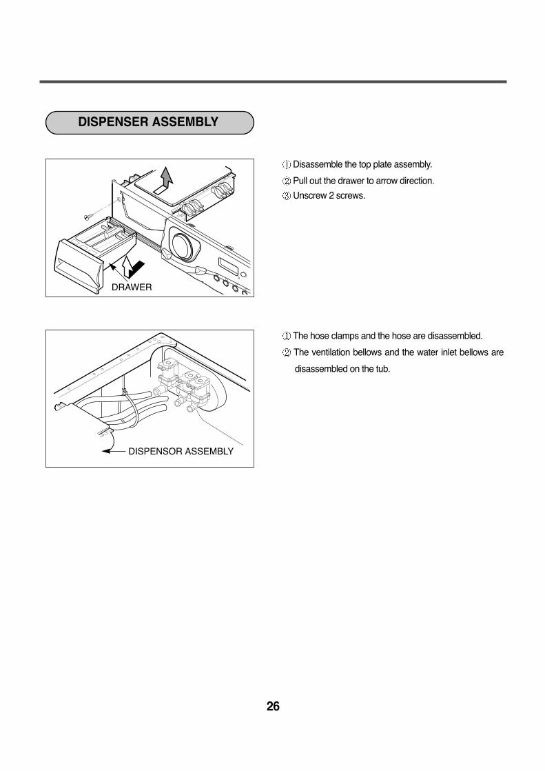
Disassemble the top plate assembly.
Pull out the drawer to arrow direction.
Unscrew 2 screws.
The hose clamps and the hose are disassembled.
The ventilation bellows and the water inlet bellows are
disassembled on the tub.
DISPENSER ASSEMBLY
DISPENSOR ASSEMBLY
DRAWER
27
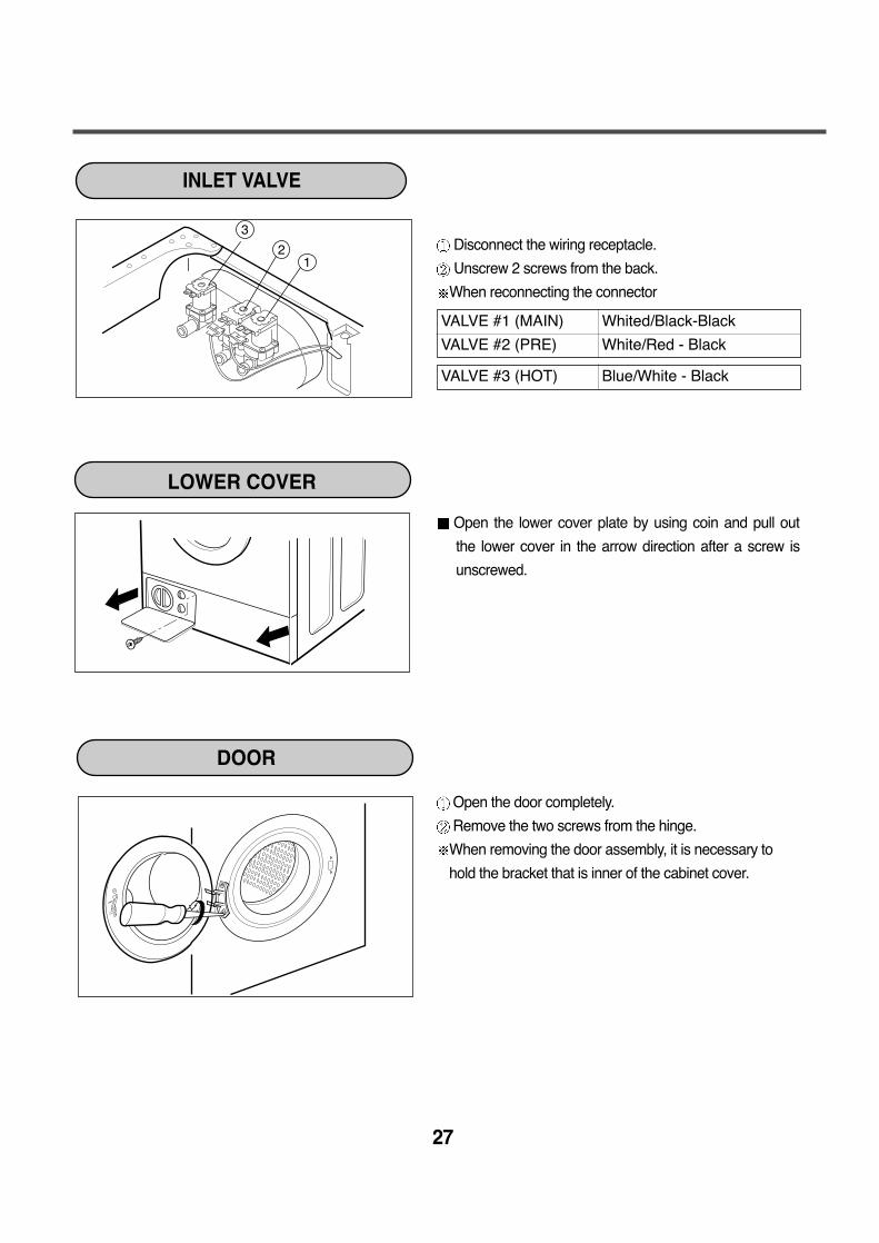
Disconnect the wiring receptacle.
Unscrew 2 screws from the back.
When reconnecting the connector
Open the lower cover plate by using coin and pull out
the lower cover in the arrow direction after a screw is
unscrewed.
Open the door completely.
Remove the two screws from the hinge.
When removing the door assembly, it is necessary to
hold the bracket that is inner of the cabinet cover.
12
3
INLET VALVE
LOWER COVER
VALVE #1 (MAIN) Whited/Black-Black
VALVE #2 (PRE) White/Red - Black
VALVE #3 (HOT) Blue/White - Black
DOOR
28
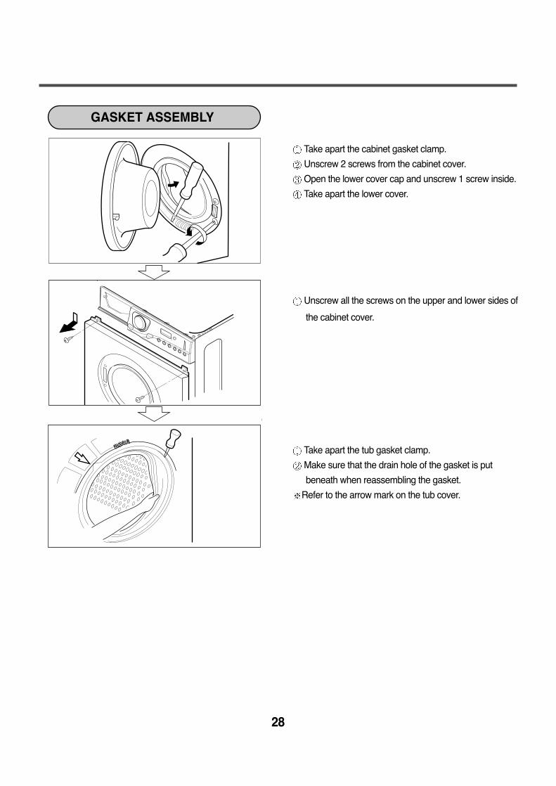
Take apart the cabinet gasket clamp.
Unscrew 2 screws from the cabinet cover.
Open the lower cover cap and unscrew 1 screw inside.
Take apart the lower cover.
Unscrew all the screws on the upper and lower sides of
the cabinet cover.
Take apart the tub gasket clamp.
Make sure that the drain hole of the gasket is put
beneath when reassembling the gasket.
Refer to the arrow mark on the tub cover.
GASKET ASSEMBLY
29
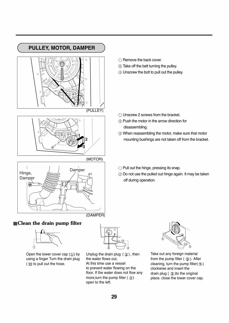
Remove the back cover.
Take off the belt turning the pulley.
Unscrew the bolt to pull out the pulley.
Unscrew 2 screws from the bracket.
Push the motor in the arrow direction for
disassembling.
When reassembling the motor, make sure that motor
mounting bushings are not taken off from the bracket.
Pull out the hinge, pressing its snap.
Do not use the pulled out hinge again. It may be taken
off during operation.
Hinge,Damper
Damper
12
3
PULLEY, MOTOR, DAMPER
(PULLEY)
(MOTOR)
(DAMPER)
Open the lower cover cap ( ) byusing a finger Turn the drain plug( ) to pull out the hose.
Unplug the drain plug ( ) , thenthe water flows out, At this time use a vessel to prevent water flowing on thefloor. If the water does not flow anymore,turn the pump filter ( )open to the left.
Take out any foreign materialfrom the pump filter ( ). Aftercleaning, turn the pump filter( )clockwise and insert thedrain plug ( )to the originalplace. close the lower cover cap.
Clean the drain pump filter
1 3 2
3
2
Cap(Remaining Hose)
Screw
Pump Outlet Hose
Tub Pump Bellows
30
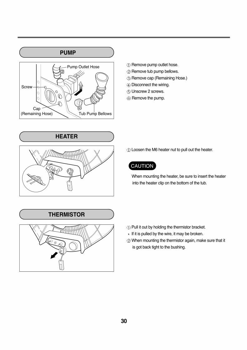
Remove pump outlet hose.
Remove tub pump bellows.
Remove cap (Remaining Hose.)
Disconnect the wiring.
Unscrew 2 screws.
Remove the pump.
Loosen the M6 heater nut to pull out the heater.
When mounting the heater, be sure to insert the heater
into the heater clip on the bottom of the tub.
Pull it out by holding the thermistor bracket.
If it is pulled by the wire, it may be broken.
When mounting the thermistor again, make sure that it
is got back tight to the bushing.
PUMP
HEATER
THERMISTOR
CAUTION
31
SWITCH ASSEMBLY, DOOR LOCK
WHEN FOREIGN MATERIAL IS STUCK BETWEEN DRUM AND TUB
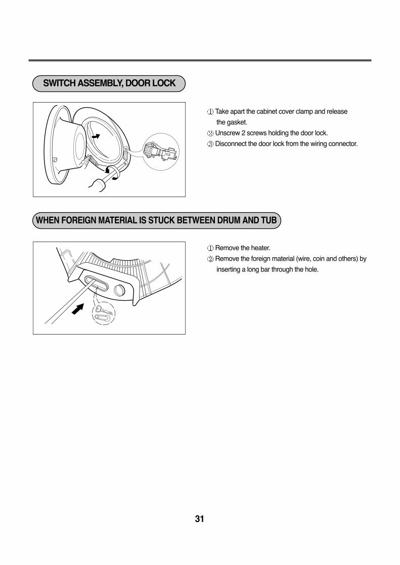
Take apart the cabinet cover clamp and release
the gasket.
Unscrew 2 screws holding the door lock.
Disconnect the door lock from the wiring connector.
Remove the heater.
Remove the foreign material (wire, coin and others) by
inserting a long bar through the hole.
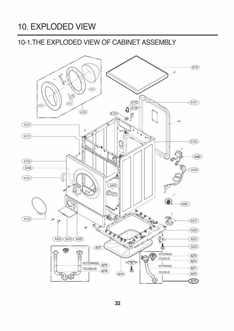
10-1.THE EXPLODED VIEW OF CABINET ASSEMBLY
32
10. EXPLODED VIEW
A151A153
A152
A150
A134
A485
A140
A480
A210
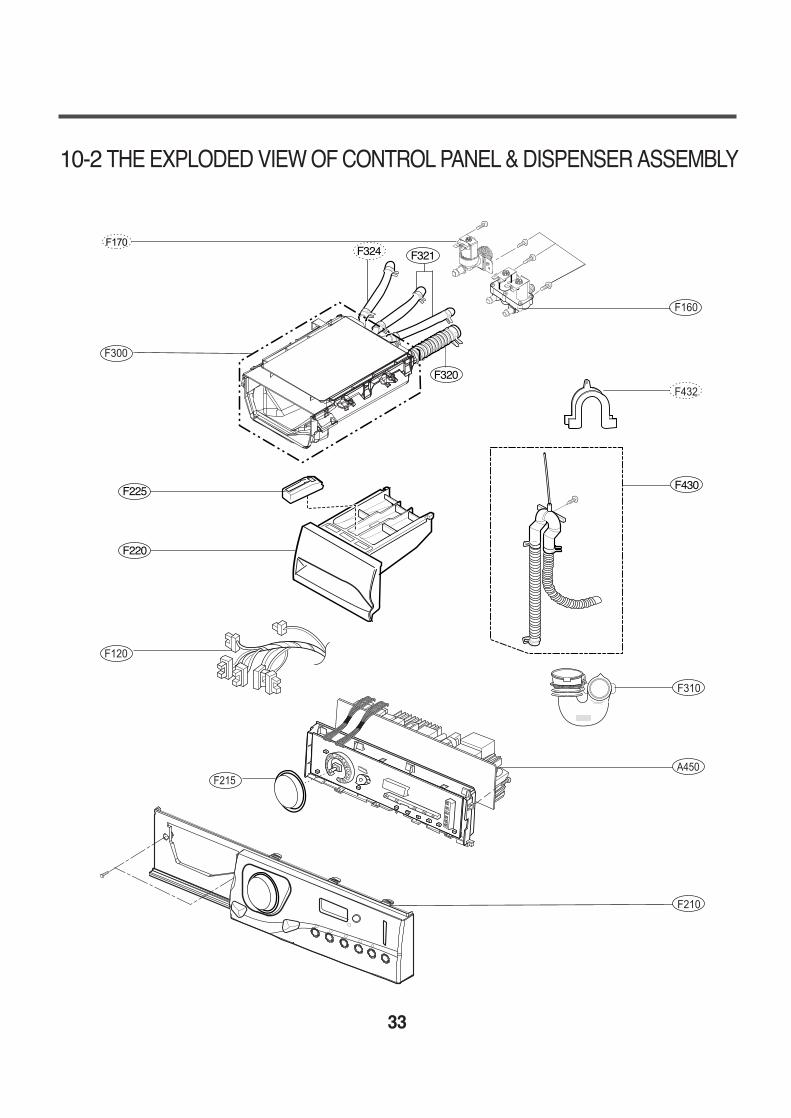
10-2 THE EXPLODED VIEW OF CONTROL PANEL & DISPENSER ASSEMBLY
33
A450F215
F430
F321
F320
F324
F220
F225
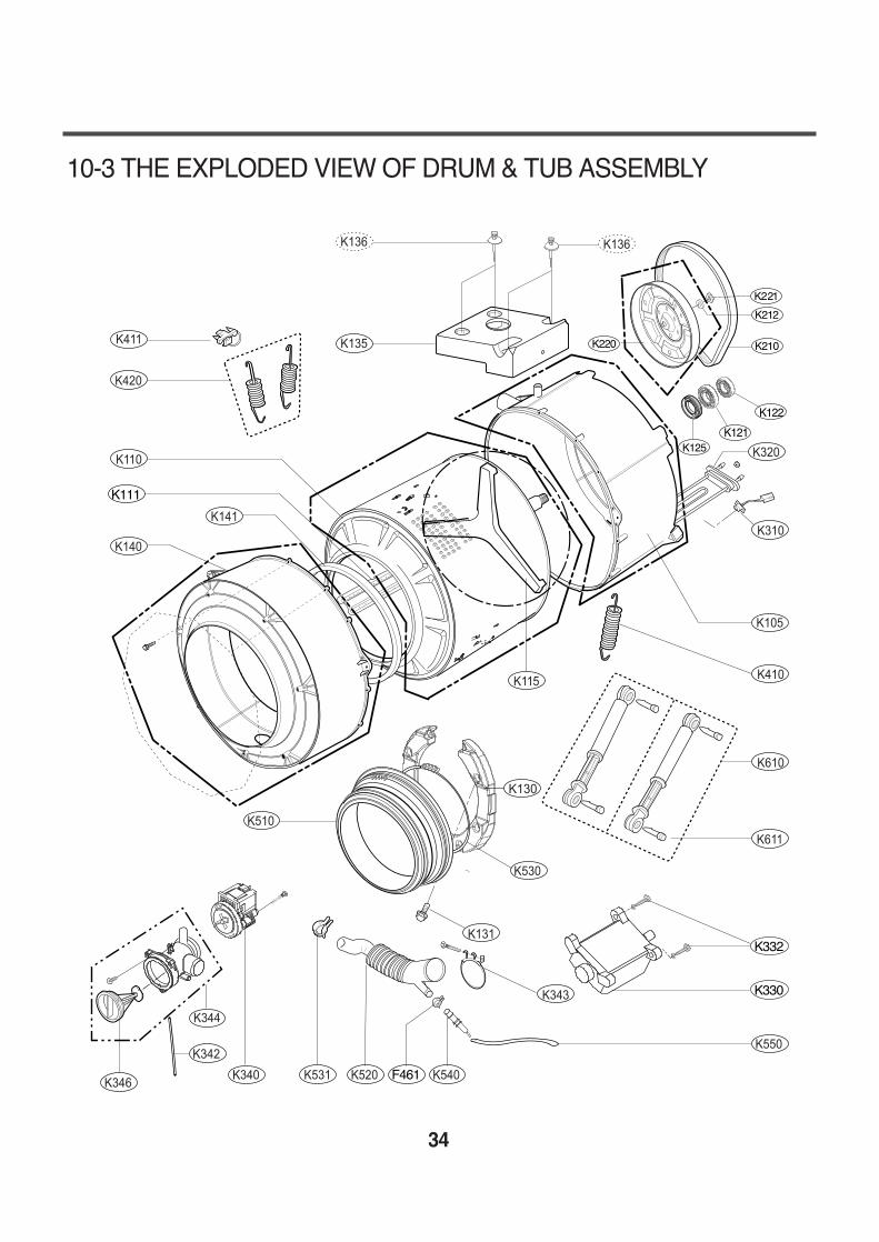
10-3 THE EXPLODED VIEW OF DRUM & TUB ASSEMBLY
34
K330
K111
F461
K122
K121
K332
K346
K342


![Features FTP [호환 모드]The washing is the result of the cooperation of temperature, time mechanic and chemistry The water temperature has the biggest Washing HOT-TEMP mechanic](https://img.pdfslide.us/doc/110x75/5f587db2f76c7259873065b1/features-ftp-eeoe-the-washing-is-the-result-of-the-cooperation-of-temperature.jpg)