Embed Size (px)
Citation preview

3 1176 01345 7057 3
DESC 23 194ß £,--, ..&"&.
(JJ£-JL~1>7
u„j- • fi^r
NATIONAL ADVISORY COMMITTEE FOR AERONAUTICS
WARTIME REPORT ORIGINALLY ISSUED
May 19^ as Advance Restricted Eeport IÄE27
THE EFFECT OF INTERNAL PRESSURE • OH THE BUCKLING- STRESS
OF THIN-WALLED CIRCULAR CTU^jDERS UNDER TORSION
By Harold Crate, S. B. Batdorf, and George W. Baab
Langley Memorial Aeronautical Laboratory Langley Field, Va.
NACA NACA LIBRARY
m,M|KlfiTnN LANGLEY MEMORIAL AERONAUTICAL WASHINGTON LABORATORY
Langley Field, Va. NACA WARTIME REPORTS are reprints of papers originally issued to provide rapid distribution of advance research results to an authorized group requiring them for the war effort. They were pre- viously held under a security status but are now unclassified. Some of these reports were not tech- nically edited. All have been reproduced without change in order to expedite general distribution.
L - 67
NACA ARR No. L4E27
NATIONAL ADVISORY COMMITTEE FOR AERONAUTICS
ADVANCE RESTRICTED REPORT
THE EFFECT OF INTERNAL PRESSURE ON THE BUCKLING STRESS
OF THIN-WALLED CIRCULAR CYLINDERS UNDER TORSION
By Harold Crate, S. B. Batdorf, and George W. Baab
SUMMARY
The results of a series of tests to determine the effect of internal pressure on the buckling load of a thin cylinder under an applied torque indicated that internal pressure raises the shear buckling stress. The experimental results were analyzed with the aid of previously developed theory and a simple interaction formula was derived.
INTRODUCTION
The curved metal skin of a modern airplane in flight is subject to stresses that may cause the skin to buckle, and proper design of airplane structures requires a knowledge of the stress conditions under which buckling will occur. The ability to estimate the buckling point under combined loading conditions is of particular importance.
In order to determine the effect that normal pres- sure, or air loads, might have on the critical stress for curved sheet, two preliminary tests were made (ref- ences 1 and 2). A pronounced increase in critical stress with increase in normal pressure was found, and the subsequent interest shown by the aircraft industry in this subject indicated the desirability of further study.
No well-established theories for buckling of curved- sheet panels either in torsion or under hydrostatic pressure are available; however, satisfactory theories for buckling of complete cylinders under these loadings have been advanced (references 3 and 4). In order to effect some correlation between theory and experiment,

NACA ARR No. L4E27
therefore, an Investigation was made of the influence of •Internal pressure on the critical stresses of thin cylinders in torsion. Experiments were conducted to determine the critical shear stresses for four cylinder lengths at a number of different internal pressures. The theories and the experimental data were used in con- Junction to determine an interaction formula for the buckling of cylinders of moderate length under the com- bined action of torsion and internal pressure.
SYMBOLS
E Young's modulus of elasticity, psi
G shear modulus of elasticity, psi
LQ length of cylinder without rings, inches
L length of cylinder between rings, Inches
t thickness of cylinder wall, inches
d diameter of cylinder, Inches
r radius of cylinder, Inches
p internal pressure of cylinder, considered positive when it produces tensile stresses In cylinder walls, psi
(p _) critical pressure in the absence of torsion T=^ (negative according to sign convention
adopted for p), psi
T shear stress In cylinder walls due to applied torque, psi
Tcr value of shear stress when cylinder Is at the point of elastic instability, psi
(T ) critical shear stress in the absence of P-° Internal pressure, psi
R_ pressure ratio ((pcr)T=o,)
NACA ARR No. L4E27
^s shear-stress-ratio
fcfc)
q exponent of Ra in the interaction formula
6 rotation of free end- of cylinder, radians
Ka coefficient used in Lundquist's empirical formula (appendix A)
y,y, differences in strain-gage readings
H Poisson's ratio
SPECIMENS AND TEST PROCEDURE
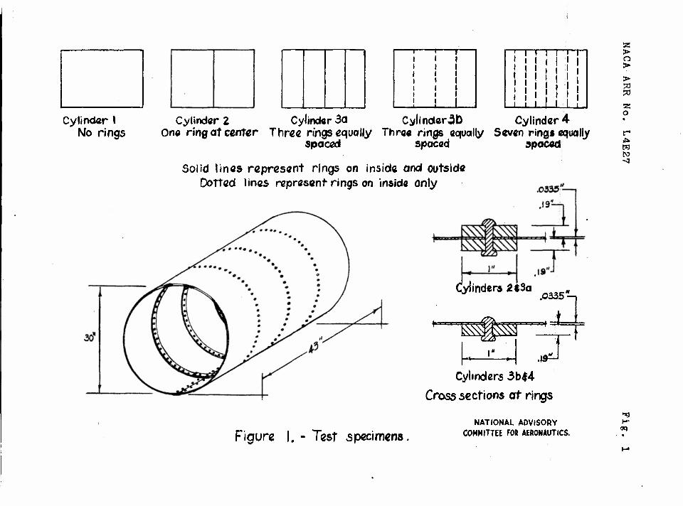
Diagrams of the test-cylinder construction and ring systems used are given in figure 1. The cylinder was made from 0.032-inch 24S-T aluminum-alloy sheet closely riveted around two heavy steel rings, one at each end. The sheet was Joined along an element of the cylinder with a butt joint covered with a single strap on the outside. Rings made of 24S-T aluminum alloy were added to this cylinder and divided it into shorter cylinders, the lengths of which were equal to the ring spacings.
Figure 2 is a photograph of the apparatus used to test the cylinder. The ends of theft cylinder were closed by heavy flat steel plates in order that air could be maintained under pressure inside the cylinder. The weights of the steel plate and test ring at the free end of the cylinder were neutralized by an upward load on one of the torque arms. Rotations of the free end of the cylinder relative to the floor were measured by a pair of dial gages.
Observed buckling loads at zero and at low internal pressure were determined as the loads at which there was a sudden snap of the cylinder to the buckled state. This snap action was in many cases preceded by a slow growth of visible wrinkles in the cylinder walls as the load increased and a greatly increased rate of growth of the wrinkles at close proximity to the snap-buckling load. With increases in the internal pressure, the
ITACA ARR HO. L4E27
snap decreased In violence until it was no longer observable. In these cases the buckling load was esti- mated, on the basis of visual observations, to be that load at which the rate of growth of wrinkles with load was comparable with the rate of growth of wrinkles just prior to buckling in those cases in which snap buckling did occur.
The Southwell method of determining the critical stress of specimens with initial eccentricities was assumed to be applicable to cylinders subjected to torsion and was used as a check on the visual determi- nation. Two electrical strain gages were mounted on opposite sides of the cylinder wall at the crest of a buckle, the location of which was determined by means of a preliminary buckling test. The difference y in readings of the strain gages on opposite sides of the cylinder wall provided a numerical measure of the dis- tortion as the wrinkles grew. The Southwell method was applied by plotting (y - J^)/(T " Ti) against y - yx where y-^ and T^ were arbitrarily chosen initial values of each quantity (reference 5). The inverse slope of the straight line formed in this manner is T - T. where T ^ is the desired critical stress, cr 1 cr
DISCUSSION OF RESULTS
In figure 3 the shear stress calculated from the external load on the; cylinder is plotted against the corresponding rotation of the free end for various values of ring spacing and internal pressure. The solid lines give rotations computed by the formula
B _ T 2L0
in which G was assumed to be 3,970,000 psi.
Prior to buckling, the stiffness of the cylinder in torsion (slope of the curves) is essentially unaffected by the internal pressure or by the ring spacing. The rotations measured were slightly greater than those predicted by the formula. This result may be attributed

NACA ARR No. L4B27
to the method of measurement, which considered as rota- tions many other, small effects, such as bending of the column supporting the cylinder, distortion of rivets and rivet holes, and taking up slack in the bolt holes in the end plates.
The. experimental buckling stress in torsion without pressure is compared with the predictions of Donnell (reference 3) and Lundquist (reference 6) in the fol- lowing table:
L/d Critical shear stress, ksi
Experimental Lundquist Donnell
0.18 .36 .72
1.43
5.8 3.9 3.0 2.3
6.0 4.2 3.0 2.3
7.9 4.9 3.3 2.3
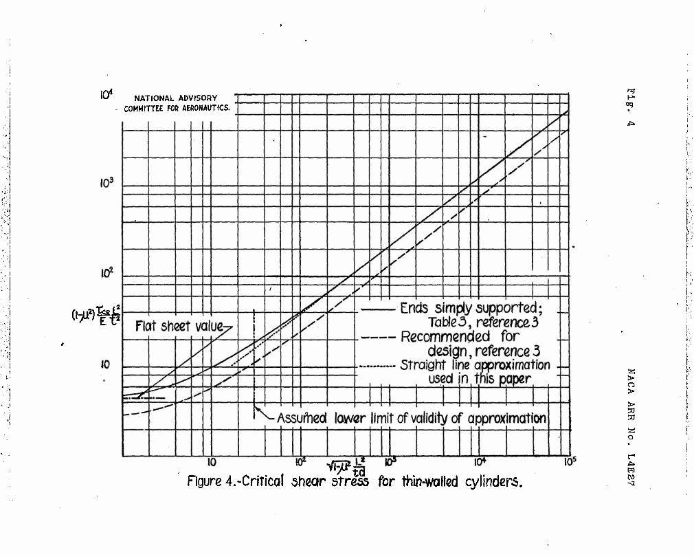
Lundquist1s formula was derived for stress at failure. Except for very short cylinders, however, the shear buckling stress and the stress at failure are essen- tially the same. Donnell's theoretical curve (solid curve of fig. 4) and Lundquist's empirical formula are discussed more fully in appendix A.
In figure 5 the buckling stresses under torsion are plotted against the internal pressure for each cylinder; this figure indicates that the buckling stresses Increase as pressure Increases. The results were essentially the same whether the visual or the Southwell method of determining buckling loads was used, although the Southwell method usually gave slightly higher loads than the visual.
The buckled cylinder could be returned to the unbuckled state either by decreasing the torque or by increasing the pressure. The loads at which the buckles disappeared were determined visually for cylinders 1, 2, and 3a, and are also shown in figure 5. These loads were not recorded, however, for the remaining cylinders because of a large scatter in the readings. This

6 NACA ARR No. L4E27
scatter Is attributable to the fact that, as the cylin- ders became shorter, the disappearance of the buckles became more gradual and the visual selection of a "point of disappearance" became difficult. In the case of cylinder 2, in which the readings are relatively definite, the location of the curve indicating disap- pearance of buckles was the same for either an increase of pressure or a reduction of torsion.
The method used to find the interaction formula best representing the experimental data is given in appendix A. The analysis leads to a formula of the type
Rsq + Rp = 1
where the value of the exponent q depends upon the assumptions made for (Pcr} _
an^ (TCrV- " ^or
cylinders of moderate length, which according to Donnell's analysis satisfy the inequality
3°a <$< 4 the exponent q is equal to 1.89 to 2 using Tcr derived from Donnell's theoretical curve, the exact value depending on the value of L /td concerned. Y/hen TCI> derived from Lundquist's empirical formula is used, q = 2.17.
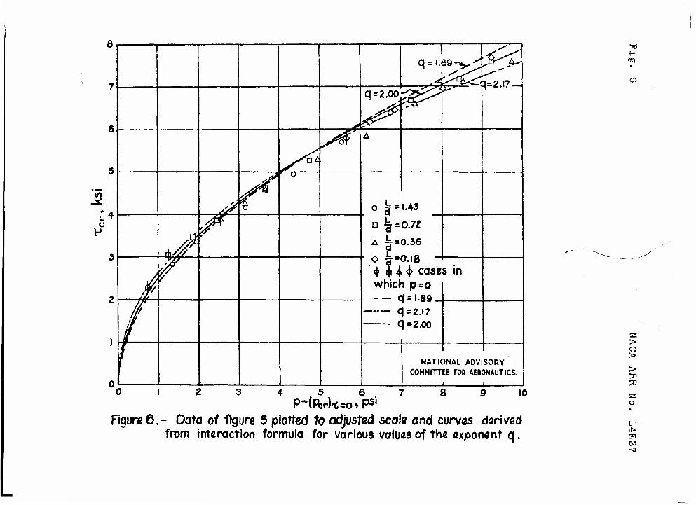
In figure 6, curves representing the exponents 1.89, 2, and 2.17 are drawn through the experimental data of figure 5 replotted by a method explained in appendix A. The three curves lie close together and, so far as fit of data is concerned, little basis exists for a choice among them. Simplicity and proximity to the average value, however, recommend use of q = 2. The equation then becomes
Rs2 + Rp = i
NACA ARR No. L4E27
The parameter L /td, which according to theory determines buckling behavior, may be varied by changing the length, thickness, diameter, or any combination of dimensions. For this reason, the restriction of the tests to one thickness and one diameter probably does not constitute a significant loss In generality.
The question of the applicability of the formula to curved panels Is discussed briefly In appendix B.
CONCLUSION
The critical stress of a cylinder in torsion increases as the internal pressure increases. The fol- lowing interaction formula was found to represent approximately the buckling of a cylinder of moderate length under the combined effects of torsion and internal pressure:
Rs2 + Rp = 1
where Rg is the ratio of critical shear stress with Internal pressure to critical shear stress without internal pressure and Rp is the ratio of internal pressure to the critical pressure in the absence of torsion.
Langley Memorial Aeronautical Laboratory, National Advisory Committee for Aeronautics,
Langley Field, Va.

8 NACA ARR No. L4E27
APPENDIX A
DERIVATION OP INTERACTION FORMULA
Introductory Discussion
Any attempt to determine which of the conventional types of interaction formulas best fits the experimental data presented in this paper is complicated by the question of which values to use for /p \ and Vcr;T=0 CTcr) n* Experimental values for (TCr) -n
were
obtained, but the corresponding experimental values of (p \ were not investigated because of the destruc-
tive effects on the cylinder involved in such a test. A simple experimental result makes possible a derivation of an interaction formula without necessitating assump- tions concerning stress ratios or the type of formula to be used.
The experimental data appear to indicate that the interaction curves for the four cylinders tested are identical, differing only in position. (See fig. 5.) The effect of a change of length appears to be a shift of the curve parallel to the pressure axis. In fig- ure 6 this effect is made clearer by plotting all the data to a common p-intercept. The curve for £ = 1,43
a is shifted parallel to the p-axis a distance equal to -Ypcr) (as given by equation (5) which follows) in .
order to make the p-intercept zero. Each of the other curves is then shifted the proper distance for best superposition. The relatively slight scatter shows that the experimental curves are nearly superposable.
If it is assumed that the interaction curves for different lengths of cylinder are for practical pur- poses identical, a computation of the equation for the curves from theory is possible. Among the points on the curve of figure 6 are four, indicated by modified symbols, representing the special case p = 0 for the four values of the length. Because the curve of figure ^fo represents Tcr plotted against p-(pcr^ _, these four
points represent (Tcr) _ plotted against -(Pcr) _n

NACA ARR No. L4E27 9
for various values of the length. The formula for this curve can therefore "be obtained by eliminating the length from the equations expressing (Tcr} _n a*ld
(Per} -o ln terms of L» d# and fc* The interaction curve for a cylinder of given dimensions can then be obtained by shifting the origin to make the p-intercept equal to (Pcr} _n
for that Cylinder. The interaction
formula may then be derived by finding simplified expres- sions for (Tcr) 0 and (pcr)T=o'
ellmlnatlnS L, and transforming to give the final formula.
Simplified Expressions for (Tcr) =n
Two simplified expressions for (TcrVt-n are
derived, the first based on Donnell's curve (reference 3) and the other on Lundquist's formula (reference 6).
Donnell's theoretical result for the shear buckling stress of thin-walled cylinders with simply supported ends subjected to torsion is given by the solid curve of figure 4. For cylinders of moderate length, the curve is nearly a straight line given by the equation
A \-0.53/d\-1.265 (Tor)p=0 = l.«(i) (|) da)
while for extremely large values of L /td a better fit is given by the equation of the asymptote
This essentially straight portion of the curve is included between the limits
** < {ij 2 d 1 < G| (2)

10 NACA ARR No. L4E27
At the lower limit of Inequality (2), equation (la) is in error by about 15 percent and equation (lb), by about 20 percent. (For the upper limit see reference 3.)
Lundquiat'a formula ia
v-1.35 c*or)p=0 = v(ty where valuea of Kg are given in reference 6 for varioua valuea of L/r. In order to determine a formula for Ks, the valuea of Ka were plotted against L/r on loga- rithmic paper. (See fig. 7.) When L/r > 0.5,
Ks = 1.27[J -'* '©•
At L/r =0.35 (approximately the lower limit of inequality (2) for the cylinder tested), the error in this formula 3a about 7 percent. Uae of this value of Kg leads to the formula
cr , = ..«ogri®-iM p=0
Simplified Expression for (Pcr^ _n
A formula baaed on work by von Miaes and developed at the David Taylor Model Baain (equation (10) of refer- ence 7) for the buckling of a cloaed cylinder under hydroatatic pressure may be written
.(p . ••«^r If, aa in the inequality (2),
30|< &

NACA ARR No. L4E27 11
the denominator of equation (4) remains within 10 percent of unity, so that, to this degree of approximation,
-(pcr)T=0 = 2-K(l/'S <5>
The negative sign appears because in the present paper internal pressure is considered positive.
The Interaction Formula
For the sake of generality and, at the same time, of simplicity in the derivation of the interaction formula, equations (1) and (5) may be written
(T°r)P=0=rK2Lnf2(d't) (6)
"(P°*0T=O
= V"*!**^ (7)
where K^ and K2 are arbitrary constants, m and n are arbitrary exponents, and fj and f2 are arbitrary functions of diameter and thickness. Elimination of L gives
m/n
(Pcr)T=30 = Klfl
(Tcr)p=0 K2f2
This equation is the formula for the curve of fig- ure 6, which is a plot of Tcr against p - (PCIA _n and therefore, when p = 0, a plot of (T \ against
\ *•* /p=0 -/pcr\ n. In order to find the interaction formula,
substitute p - (pcr)T-o ln Place of ~(pcr)T-o
and
Tcr in place of (Tcr) _n and simplify the resulting
expression. Thus,

12 NACA ARR No. L4E27
P " (Pcr)T=0 = ¥l
m/n
Dividing through by ~(^cr\—n and using equations (6)
and (7) yields
(pcr)T=( + 1 =
Klfl /Tcr vm/n
K1JPtll\^2f2i
cr — m/n
(T^)p=0 p=uj
A rearrangement of terns gives
-.m/n cr
CTcr)p=0 p=ty (Pcr)T=o
= 1
If Donnell's equation (la) is used with equation (5),
n 0.53
or if Donnell's equation (lb) and equation (5) are used,
m _ 1 = g n *~ 0.5
Use of Lundquist's equation (3) with equation (5) yields
m _ 1 n 0.46
= 2.17
For purposes of simplification, let
Rs =
Rn =
cr
(T°r)B=0
P ('or),. T=0

NACA ARR No. L4E27 13
and
m •"""'' '
1 = n
Then, the final formula may be written
Rsq+.Rp= X

llj. NACA ARR No. llj.E27
APPENDIX B
APPLICATION OP INTERACTION FORMULA TO CURVED PANELS
The theoretical analysis of the buckling of a curved panel Is much more difficult than the treatment of complete cylinders. In the case of buckling under torsion alone, the boundary conditions required for panels greatly complicate the theoretical analysis. It may be presumed, however, that the added restraints make the critical stress higher than that of a complete cylinder of the same length, thickness, and curvature. The relation between the pressure and the direct stresses produced in the sheet Is also much more complicated than in the case of a complete cylinder. The axial stresses depend on the area of the end bulkhead and on the areas of cross section of sheet and 3par elements. It Is difficult to draw conclusions regarding the relation of pressure to circumferential stresses. It Is therefore not to be expected that an Interaction formula established for complete cylinders will necessarily apply to curved sheet also.
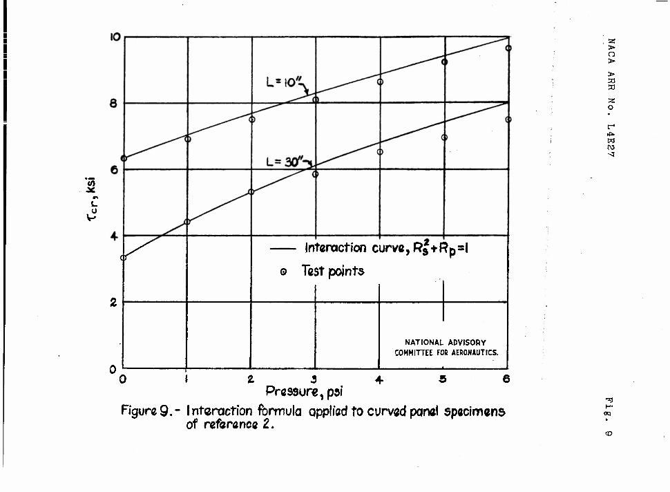
In order to determine whether the interaction formula derived in appendix A may be used to gain a rough Idea of the strengthening effect of Internal pressure In the case of curved panels, the formula Is applied to the test points of the two specimens of reference 2. Figure 8 Is a sketch of the two specimens tested. In fig- ure 9 the experimental shear buckling stresses are plotted against the internal pressure.
Curves representing the interaction formula are also plotted In figure 9» In order to apply the formula, the experimentally determined values of (Tcr) =n were
used; (Per} -n *s assUTr-e^ to be the sane as for a com-
plete cylinder of identical length, thickness, and curvature, and is found by applying equation (it.) of appendix A. Fair agreement vas obtained between the curves and the test points and the agreement might be considerably improved by a more precise method of determining (Pcr) _•

NACA ARR No. L4E27 15
REFERENCES
1. Rafel, Norman: Effect «>f Normal Pressure on the Critical Compressive Stress of Curved Sheet. NACA RB, Nov. 19lj2. .
2. Rafel, Norman: Effect-of Normal Pressure on the Critical Shear Stress ©f Curved Sheet. NACA RB, Jan. I9I4.3.
3. Donnell, L. H.: Stability of Thin-Walled Tubes under Torsion. NACA Rep. No. 1+79, 1933'
I+. Timoshenko, 3.: Theory-of Elastic Stability. McGraw-Hill Bo<>k Co*,- Inc. .;-J936, P« 1+50.
5« Lundquist, Eugene E.: mineralized Analysis of Experimental Observations in. Problems of Elastic Stability. NACA TN Ep- :658.', " 19^8.
6. Lundquist, Eugene E.: Strength Tests on Thin-V.'alled Duralumin Cylinders -in Torsien. NACA TN No. 1+27, 1932.
7. Windenburg,.-Dwight F., and. Trilling, Charles: Collapse by Instability of Thin Cylindrical Shells under External. Pressure. Trans - A.S.M.E., APM-56-2a-,-vol.-56,.Jie*..li,-Nov. 1931+, PP- 819- 825.
I I I
_L_L Cylinder I
No rings Cylinder 2 Cylinder 3a CylinoterSb Cylinder 4
One ring at center Three rings equally Three rings equally Seven ring» equally spaced spaced spaced
Solid lines represent rings on \nsioQ and outside Dotted lines represent rings on insid« only
Cylinder» 2$3a „ .0535 -
^=L & t£&
Cylinders 3b|4
Cross sections at rings
Figure I. - Test specimens. NATIONAL ADVISORY
COMMITTEE FOR AERONAUTICS.
55 > O >
> JO JO
z o
r-
to -3
OP

> o > >
2: o
r1
Figure 2.- Test setup. 1—
oq
N>

NACA ARR No. L4E27 Fiff. 3
Rotation, radians 0.005
NATIONAL ADVISORY COMMITTEE FOR AERONAUTICS.
Test data — Computed rotation,^=£x^°
Figure 3.- Shear stress-rotation curves for cylinders with various ring spacings and internal pressures.
10* NATIONAL ADVISORY COMMITTEE FOR AERONAUTICS
cy«^
Figure 4.-CriTicaI shear stress for thin-wailed cylinders.
«3
if»
S > >
w w
o
r

NACA ARR No. L4E27 Fig. 5
*£r ^^r
•»•^x rx X
do
QA#? X
fx Cyl. 1 ^-=1.43
1
^ ^
^^8
^u
CVl. 4-
^ = 0.18
1 0 . r » . t ( 5 . Ö
—° Observed visually
—0 Southwell prediction
» BucKies out, pressure increased
• Buckles out, load released
NATIONAL ADVISORY COMMITTEE FOR AERONAUTICS.
Internal pressure, psi
Figure 5.- Effect of internal pressure on critical shear stress for thin-walled circular cylinders.
8
i.
1 !
3=2.17 — q =2.oo^gJ^
j^ ~
^/Ut
^S^OT JA
&^ ru
°!r 1.43
\• 'v
- o £ = '• <M whic»
: C
c t
0.72
0.36
0.18 ~ 4> cose
i pso 1 = 1.89 - 1=2.17 1=2.00
10 /JCT
7 s in
i it K
..
NATIONAL ADVISORY COMMITTEE FOR AERONAUTICS.
i i
oq
0>
4 5 6 . P-(fcrk=co P5"
8 10
Figur« 6.- Dato of figure 5 plotted To adjusted scale and curves derived from interaction formula for various values of the exponent q.
52 > > > w
O
r* it* w -a

NACA ARR No. L4E27 Fig. 7
Ks
8
6
4
I .8
till ®—^-o Curve for tf8 plottec
rrom TaweoT rcT.t» ' Straight line approx-
imation used in this paper, |^«i2Tfe)~M <
^ \
—
•^
Ss> >
^AJ ssumed lower'limit N ^
of V alidity o topf >rox 9 N S*-
*»- (§v-55
1 NATIONAL ADVISORY
COMMITTEE FOR AERONAUTICS.
.4 .6 .8 I 4- 6 8 10
Figure 7- Value of JQ used in empirical formula for critical shear stress of thin-walled cylinders.

Fig. 8 NACA ARR No." L4E27
30-inch rib spacing
NATIONAL ADVISORY COMMITTEE FOR AERONAUTICS.
r»65
rao8i
Approx.Sf
Section of rib at center line of panel
Figure 8.-Curved -sheet panels of reference 2.
• !• II I I
Ü
— Interaction curve, RJtRp=l
© Test points
NATIONAL ADVISORY COMMITTEE FOR AERONAUTICS.
Pressure, pot
Figure 9.- Interaction formula applied to curved panel specimens of reference Z.
2 > a > > 50 ?d
z o
pd
-3
OQ
(D

TITLE: The Effect of Internal Pressure oo the Buckling Stress of Thin-Will jd Circular Cylinders under Torsion
AUTHOR1S): Crate, Harold; Batdorf, S. B.; Baab, George W. ORIGINATING AGENCY: National Advisory Committee for Aeronautics, Washington, D.C. PUBLISHED BY:
ßYJ- 7551
r-UCUSMlMO AOCMCT Ma
May' 44 UflCiisa. U.S. Eng, PAOSS niun&Anoaa 24 phntn, rilairr. graphs
Tests indicate that Internal pressure raises the shear buckling stress. Formula was developed to represent approximately the buckling of a cylinder of moderate length under the combined effects of torsion and Internal pressure. This formula makes use of the ratio of critical shear stress with Internal pressure to critical shear stress without internal pressure and the ratio of internal pressure to the critical pressure In the absence of torsion.
DISTRIBUTION: Coptes of this report obtainable only from Originating Agency DIVISION: Stress Analysis -nd Structures (7) SECTION: Structural Theory and Analysis
Methods (2)
ATI SHEET NO.: R-7-2-33
SUBJECT HEADINGS: Cylinders - Stress analysis (28505); Tubes, Thin-walled - Torsion tension tests (95247)
Al* Dflcujnaats Diwltloi, IntoUlfJoac» Doportn ofrt Air MHoriol r
AID. IICMWICAt INC." WrlgM-Ponorw» Air forte SaM Doyfon. Ohio