Embed Size (px)
Citation preview

T "EC 23 794g ACS Ho. UL21
NATIONAL ADVISORY COMMITTIE FOR AERONAUT!
WARTIME REPORT ORIGINALLY ISSUED
January 19^5 as Advance Confidential Beport LUL21
SUMMARY OF DATA RELATING TO THE EFFECTS OF WING
MACHINE-GUN AND CANNON INSTALLATIONS ON THE
AERODYNAMIC CHARACTERISTICS OF AIRPLANES
By John H. Qulnn, Jr.
Langley Memorial Aeronautical Laboratory Langley Field, Va.
NACANA s
WASHINGTON ***toma,vq _--uc. i.
NACA WARTIME REPORTS are reprints of papers originally Issued to provide rapid distribution of advance research results to an authorized group requiring them for the war effort. They were pre- viously held under a security status but are now unclassified. Some of these reports were not tech- nically edited. All have been reproduced without change in order to expedite general distribution.
\
L - 158

3 1176 01363 9068
NACA ACR No. LL|i21
NATIONAL ADVISORY COMMITTEE FOR AERONAUTICS
ADVANCE CONFIDENTIAL REPORT
SUMMARY OF DATA RELATING TO THE EFFECTS OF WING
MACKINE-GUN AND CANNON INSTALLATIONS ON THE
AERODYNAMIC CHARACTERISTICS OF AIRPLANES
By John H. ^uirn, Jr.
3Ü1WA3V-
Data obtained frcm testa of .»ode la ur.d airplane a relatln.3 to the effcct3 of various iving arrnanent instal- lations >i£.ve been collie Led and analyzed . Three type a of gun installation rero comider'rü; namoly, gun porta (submerged machine giois), protrudLn^ machine guns, and caanor. Data have been ores-anted as drag-coefficient increments of one g^n based on an sroa nqual to the square of the local wing chord and as incremental lifts for this complete Installation based on airplane (or model) win^ area.
Toe analysi3 of t^ose data rovt-alart that a wsll- de si pried {run pert shoulc' have little or no effect on 9ither the drag or maximum lift of an airplane. A well-deoigned gun opening in the let-ding edge of a wing should not exceed one-tenth of the wing thickness in height, should have provision for air flow and ba fitted with a suitable exit vent, and should be located on or a few percent of the oherd below the chord line. Gun porta that did not fall in thia category were found to cause drag-coefficient increments up to 0.0016 and to decrease maximum lift coefficient by as much as 0.12. Gun openings at least up to 25 percent of the local wing thickness in height may yield small dra3 increments, however, provided a faired noso-air-intake shape is used.
The smallest drag-coefficient increments for protruding-machine-gun installations were obtained with machine guns that protruded approximately i\. percent of the wing chord ahead of the leading edge of the wing, were located on or rear the chord line, and were faired smoothly into the wing contour, Unfaired guns with greater extensions caused drag-coefficient increments

NACA ACR No. I4L21
UD to 0.0010, and guns mounted "below the wing caused Increments of 0,003$. Gun extensions of at least 0.25 chord, however, were found to have less adverse effect on maximum lift than shorter extensions.
The drag-coefficient increments caused bv cannon installations on the win^ were decreased approxi- mately 0.0003 or O.OOOlj. b^ fairing the cannon into the wing and providing air flovr. Cannon located below the chord line causod increments of 0.00JJ3, or nearly four times the increment of ah vnfjiired cannon mounted en the ffing. I^sired cannon located on tho wing generally had little or no effect on maximum lift. Phfaired cannon located on tho wing aid faired cannon located below the win? were found to doerease tax-mum lift coefficients oy as nu.^h 13 0.09.
TNT:
A number of inve.7tl3atT.ons conducted by the Natioral Advisorv Corjnittse Tor Aeronautics during tV'e uest few -years L-.-ave dealt in part with the effects of -.ving-armarcent installations on the aerodynamic character!sbics of airplanes. The purpose of the present report is to group these data in 3ome logical faanion to facilitate their analysis and to establish, wherever possible, trend3 for correct ces'gn.
The armament installations considered fall logically into three groups: gun ports (submerged machine guns), probruding rrach^ne guns, ^nd cannon. An analysis of the data revealed some definite trends that should be of considerable aid in the design of improved ".ving- armament installations. A discussion cf bbe t.33t results and of the various factors affecting Lie aerodynamic design of v.-ing-arnam.ent installations is given in tho following sections.
SYMBOLS
CD airplane drag coefficient
CL airplane lift coefficient

NACA ACR No. li|.L21
c^ section lift coefficient
C(j section profile-drag coefficient
AGD incremental wing-gun drag coefficient based on local wing chord squared
[; S
n „2 \ Dmodel + guns " ^PnodelJ
n number of guns
c local wing.chord at center of gun installation
S wing area
t maximum win3 thickness
h height of —.in-rort c^uning
e extension of <run or cannon i*hoad of wing
Aj gun-port Inlet area
Ae exit area of gun duct
±AO Increment ( + ) or decrement (-) In maximum ,nax llft coefficient
R Reynolds number
bf angular deflection of flap
V0 free-stream velocity
V* gun-port Inlet velocity
TESTS
The data presented herein were obtained from two- dimensional wind-tunnel teats of rectangular win^s, three-dimensional wind-tunnel tests of scale models, and full-scale wind-tunnel and flight tests of airplanes, For the two-dimensional t<?sts, ehe drag was determined by the wake-survey method and lift was determined by

NACA AGR No. li+L21
Integrabing the pressure along th9 floor and ceiling of the tunnel test section (reference 1). Li all the other tunnels, lift, drag, and moment were obtained from balance measurements. Standard methods of speed determination were used in obtaining the flight-test data.
PRESENTATION OP DATA
The lift- and drag-coefficient increments, together with the important dimensions, i^re ^resented in table I for the submerged machine-gun installations, In table II for the protruding machLno-gun ir.stallatlons, and in table III for the wine-cannon installations. Drag- coefficient increments, detailed sketches, and photo- graphs of the various installations are presented in figures 1 to !;3 •
The tables alone should not b3 used to compare the various installations but shovld be supplemanted by comparing the plot3 of dras-coef "icient increment agaln3t lift coefficient. Because of experimental inaccuracies and the variation with lift coefficient, the drag increments at any one lift coefnicient may not £ive a true indication of the relative merits of diffsr.-nt installations.
Lift effects are s^own for onlj three-dimonolonal nod3Is; the incremental coefficient is for the complete armancnt installation and is based on total win^ area. In order to facilitate the tJialy3is and use of the drag data, }"ow3vei, lihe increments have been presented in term3 of the coefficient ACn .
•Jc
P.rjCISIO? OF MI AST"i'-.Y, iNVS
In order to facilitate comparison of the data obtained in the Cifferent tunnels, probable errors in drag-coefficient increment have ^een estimated and are presented in tables I to III. The oxperimsntal accuracy was assumed to be ±1 ocrc3nt of the total measured drag for all data not obtaLned by the wa:ro-survey method. This accuracy is thoujht to approrimate the limits within which a Doint may be checked, as determined from past experience.

NACA ACR No. TJ|L?1
Ha determining the error involved in the wake-survey data, a slightly different procedure was followed. In addition to a probable error of 1 percent in the drag- coefficient increment, there was the possibility that the 3panwise drag curve might not taper off to the correct plain-wing drag at either end. For each of the tests made by the wa?ce-survey method, therefore, the error given in tables I to III was obtained from the expression:
Error = 0.01 AGTJ + Estimated error due to curves not returning to correct base lines
The values of the probable errors in the drag- coefficient increments cf armament installations as measured on a wing model and on an airplane or model of the airplane differ considerably. '.This difference occurs because the drag; of a g-ui installation on a wing mod9l often is of th.3 same ordor of magnitude as the drag of the model, wherea3 the drag of the armament installation en a complete airplane is but a very small part of the airplane drag.
DISCUSSION
The discussion of the data presented is divided into three sections: gun-port, protruding machine- gun, and cannon installations. Under each of these headings, the effect of savoral significant parameters on the lift and drag characteristics of the model upon which the guns were mounted is discussed. Although the greater part of the discussion deals with the effect of wing guns on the drag of the airplane, maximum lift effects are presented wherever available. The available tests showed that the effects of wing-armament instal- lations on the pitchlng-momont characteristics of an airplane were negligible. Pitching-moment data, therefore, are not presentod.
In several cases, the results obtained with gun installations on airplanes do not agree with the results obtained with gun installations on models. The effect of an actual gun installation depends to a large extent upon the surface condition of the wing upon which it is mounted, because rough wing surfaces or pocr wing construction may partly mask the adverse effects of a

NACA ACR No. Llj.L21
relatively poor gun installation. In order to find the true effect of an armament Installation on a particular airplane, therefore, fall-scale data should be used. Data from model tests aro used in the deter- mination of the separate effects of the various factors that enter Into the terodynamic design of a wing- armament installation.
Gun Ports (S'lbmerg-jd teacliine Guns)
The effects of a ffell-deaiyied gun nort on the aerodynamic characteristics of a smooth '7ing are small. The Important factors to be considered In the design of such a gun port are discussed in tho following order: the air flow through the £v.n ^ort, the height of the port with resoect to the win-; thiclcness, and the position of the gun Dort with respect to the wing chord line.
The effect of air flow on the drag-coefficient Increment of a gun nort ".vas Investigated cy tests with and without air flow on a rod?l of the wing of the XF-)L7P airplane (table I, fig. 1). At a lift coeffi- cient of 0.2 without air flow the g^n port caused a drag-coefficient incretn3nt cf 0.CD05, whereas the same port with air flow caus3d an increment of onlv 0.0001. r'roTi th1 s result it ao*->ears advantageous to provide a suJtaole exit vent lor the gun port and to permit the air to flow around the g\in and to exhaust at sone 'ooint on the wing. In this test the air was vented to the upper part of tho aileron slot. In prac- tice, air usually flows through the gun port, although a suitable exit vent is rarely provided. In most cases, th3 air that enters the gun port lealcs out into the air stream through a wing joint or through the fuselage. The advantage of having air flowing through the gun port is thus partly realized, but the gain Is often more than off3et by the power required to overcome the loss resulting from leakage,,which causes an external disturbance. Inasmuch as so.139 air almost always flows through the port of an actual installation, the greater part of the discussion will deal with the analysis of the aerodynamic effects of othar parameters with air flowing.
The wing of the XP-65 airplane (table I, figs. 2 and 3) and a model of the modified XP-Ii-1 airplane

NACA ACR No. lij.L21
(table I, figa. ij. and 5) wore tested to find the effect of gun-port height on the drag-coefficient increment caused by a gun port. (See' reference 2.) ' Increasing the gun-port height is shown to increase the drag increment, The drag increment for the gun port on a model of the XFij.TJ-1 airplane, which has a large inlet height (table I, figs. 6 and 7) waa about the same as the increment for the larger gun port on the model of the modified XP-lj-l airplane. From inspection of these data and of those for the XP-l^B wing section, gun ports having a height up to approximately 10 percent of the wing thickness (0.10t) appear to cause little or no increase in the wing drag. Tests of the Flj.U-1 (table I, figs. 8 and 9) and XF2A-2 (table I, figs. 10 and 11) airplanes in the Langley full-scale tunnel show lower drags than would be predicted from model tests. Inasmuch as the w'.ngs of those airplanes were unusually rough, it might be expected that the adverse effects of large gun-port heights are partly masked in these cases.
A low-drag g^in port with three type3 of front opening was developed (table I, figs. 12 and 13, and reference 3) to obtain a gun port having a height that was large with respect to the wing thickness and yet having low drag. The gun openings, which are 25 percent of the thickness of the bulged po±*tion of the wing in height, owe their low-dra3 properties to a faired nose- air-intake shape at the entrance. These inlets were designed by use of the findings of the tests reported in reference Ij.. If it 3s necessary to have an opening that is large with respect to the wing thickness, a similar faired nose-opening shape should be used. Large openings may possibly be avoided by moving the breech of the gun for aiming rather than the muzzle. Small openings and consequently low drag increments would then be possible.
In order to determine the effect on drag of the position of the gun ports with respect to the chord iine of the wing, a comparison was made of the drag- coefficient increments for the gun ports 0.5 percent chord (0.005c) and 2.6 percent chord (0.026c) above the chord line of the wing of the XF2A-2 airnlane (table I, figs. 10 and 11, and reference 5). The gun- port position nearer the chord lino was found to result in the smaller Increment. Similarly, it is seen from table I and figure 3(a) that a gun port 0.0l8c high

8 WBBKKKKm NACA ACR No. li|L21
by 0.033c wide centered on the chord line of a model of the wing of the XP-63 airplane caused a negligible increase in drag. Comparison of the spanwise drag surveys for similar gun oorts on and slightly below the chord line (fig. 3)» however, showsno important difference resulting frc.11 positions on the chord line and below the chord line. Because of the limited travel of the survey apparatus, it was difficult to obtain a complete span»ise drag survey for these gun ports, but reasonable estimates of the extent of the curves and the area under them (proportional to the drag increment) ma> be mado. Gun ports 0.012c by 0.026c and 0.015c by 0.027c centered O.Ollp below the chord line, both of which are smaller in height and width than the 0.0l8c by C.0>5c gun povt on the chord line, caused sonewhat larger drag increments than the gun port on the chord line. The 0.033c by 0.033c gun iDort centered below the chord Itno, however, probably has a slightly smaller drag t>ran tbe 0.021c by 0.033c gun nort on the chord line. These results indicate that gun ports centered on or slightly below the chord line caused smaller dreg, increments than gun ports centered above the chord line. A reasonable explanation for this conclusion .1^7 be obtained from consideration cf tbe stream lines about the wing at the cruising lift coefficient. If the cruising lift coefficient Is equal to or greater than the design lift coefficient of the wing, the stagnation point Is at or 3lightly below the chord line. Gun ports contered above the chc^d lino, In a hi-^h-velocity region, thus have more adverse effect than gun oorts located in the low-velocity region in tbe neighborhood of the stagnation point.
The drag-coefficient increments for gun ports on a model of tho wing of the XA-I4.I airplane, anere no air flow was provided (table I, figs. 1I4. to l6), showed that the gun nort3 on or near the chord line caused larger drag increments than those above or below the chord line, and these drag increments without air flow in nearlv evorv case were much larger than anv
1 measured with air flow. One such gun port, l6— percent
of the wing thickness In height and centered slightly above the chord line, caused a drag-coefficient Increment of 0.0018. Without air flow, the gun ports on or near the chord line, depending upon their size, probably

NAGA ACH No. l4L21
spoil flow on both surfaces, whereas gun ports above or below the chord line spoil flow on only one surface. The gun ports above the chord.line caused larger drag increments than gun ports centered below the chord line even without air flow.
Three gun-port configurations were tested on the T-51B airplane in the Langley full-scale tunnel (table I, figs. 17 and 18). The gun port was tested (1) in tho service condition (gun port open), (2) covered with tape that was torn to simulate the con-iitcn after firing, and (3) covered with metal plates having holes just large enough to allow the passage of a bullet. The results of these tests are given in table I and figure 18. The taped gun ports gave slightly lover drag increments than the service gun ports. The cover plates having small holes resulted in the be3t arrange.nsnt tested on this airplane.
An examination of tho effect of the various gun ports on the inaximum lift coefficient (table I) indicates that few of the installations had serious uö"verse effect. The large less in maximum lift coefficient of 0.12 on the P-51B airplane probably occurred because the gun port was 26 percent of ths win.3 thickness in height.
Protruding Machine Guns
Because of apace limitation or other considerations, it is often r9ce3 3ary to install machine guns that protrude ahead of tho leading edge of the v/ing. The most important variables affect\n£ the design of a protruding machine-gun installation from aGrodyncmlc considerations are tho position of the gun with respect to the chord line and the oxtension of the gun barrel ahead of the leading edge of the wing.
Several gun extensions and two oositions with respect to the wing chord line were tested on tho XF2A-2 airolane in the Langley full-scale tunnel (table II, figs. 19 and 20). An extension of 0.028c caused a lower drag-coefficient increment than a 0.139c extension, bub the drag of the 0.159° extension was essentially the same as that of the 0.25l^c extension. The 0.139c extension wu3 tested 0.005c and 0.02oc above the chord line. The oosition nearer the chord line

10 NACA ACR No. li|.L21
yielded the lower drag increments. Protruding machine- gun installations were also tested on a model o.f the modified XP-lj.1 airplane and on the F6F-3 airplane (table IT, figs. 21 to 23). The 0.100c extension on the modified XP-l+l airplane caused about the same drag as the 0,159c extension O.OOpc above the chord line of the wing o.f the XF2A-2 almla/ie. The lowest drag- coefficient increment for protruding machine guns MCrj = O.OOGl"'! was obtained vMth the [j.-oercant-chord
extension mounted 0.02c above the chord line of the wing of bhe Fo^-J aimiane. For these tests, the guns were provided -with a v/e 11-de signed smooth fairing. The 0.19c gun extension on the XP-65 win.^ moJel (table II, ligs. 2I4- and 23) cau30d the highest drag- coefficient increment (&"rc ~ O.OOIO} of any protruding gun mounted on or near tho chord lin3. The largo drag increment of th4s installation As cua to the laminar flc.v that was spoiled en the low-drag wing. From th3 foregoing results, it u^nsni-a that short well-faired gun extensions and mo^jitLiXg pos'.ti 0113 on or near th9 chord line v/ill have the lowest drag.
•Chd9r3lvng machine guns were tested on a model of the wing of the XF-65 c.irolane, on the F-63A airplane, and on a model of tho XA-26 eirplane. Scotches and drag data for these arrang'viients are presented in table II and figures 2ii to 27. H coupcrison of the drag of the underslun^ arrangements and the drag of the arranceirents having guns fixed at cr near the chord Una (table II) shows that the drag-coeffLcient increments caused by the underslung guns, often ns mi-.ch as 0.0033, are e-cessive. At a lift coefficient of 0.2, the vndersl^ng arrangement on the XP-63 '-ving model caused an ircr3ment a^oroxinatoly 60 vereint greater than tho gun mounted en tue chord 11ns. (See fig. 25.) The installation on the P-65A airplane, which represents the manufacturer's best attempt to reproduce the model installation, caused a c^rag increment approximately twice that of the model instal- lation. Sealing tve ejection slots and the annular snace between the gun barrel and fairing on the air-plane reduced the crag increment of this installation slightly. The poor agreement between the installation and the model installation tested in the Langley two-dimensional low- turbulence pressure tunnel is probably due to leakage around the barrel through the holes in the cooling Jacket en the actual installation.

NACA ACR No. IJ+L21 «••MBMi 11
Some observations concerning the effect of gun extensions on maximum lift may be made by comparing the decrements measured öh the XF2A-2 airplane in the Langley full-scale tunnel (table II). The 0.028c extensions mounted 0.026c above the chord line decreased the maximum lift coefficient O.llj., whereas the 0.159° extensions mounted 0.005c above the chord line caused a decrease of 0.13. The 0.25l|.o extension, however, mounted 0,005c above the chord line decreased the maximum lift coefficient by 0.09. It appears that gun extensions of at least C.25c ar9 less detrimental to maximum lift than shorter extensions - probably because the separation at the tip of the short extension passes close to the vpper surface of the wing and spoils the flow, whereas th^s separation for the long guns masses farther above the wing and has le3s detrimental effect.
A. number of wing-gun f-iirings were tested in flight on the FI±F-3 airplane to improve tte maximum lifb and stalling characteristics. (See reference 6.) Photo- graphs of the various fairings are presented in fig- ure 2dm The addition of unfairad gui3 tc the otherwise clean airplane caused a considerable increa3e in stalling speed. Tests of a number of fairings indicated that a faired sealed opening for the submerged gun and a sealed fairing on the protruding gun resulted in practically no change In stalling speed from that of the plain wing and al3o aided in correcting the poor stalling characteristics of the airplane. unsealing these fairings, however, caused a loss in maximum lift coefficient of 0.2b. The pertinent data for these arrangements are given in table II.
Wing-Cannon Installations
Wing-canncn installations may be best compared on the basis of the mounting oosition with respect to the chord line, the type of cannon fairing, and the provision for air flow.
Two underslung and one oartly submerged cannon Installations were tested on the X?2A-2 airplane in the Langley full-scale tvnnel (table III, figs. 29 and 30). At a lift coefficient of 0.2 the best underslung arrangement caused a drag-coefficient increment ^ACD = 0.0033} 170 percent greater than the partly

12 MHHHMHI NACA ACR No. IJ+L21
submerged installation. This result again shows that the drags of underslung arrangements are excessive.
Cannon installations on a conventional airfoil section and several low-drag sections were tested in the Langley two-dimensional low-turbulence pressure tunnel (table III, fig3. 51 and 32). AS might be expected, the increment in drag coefficient was greater on the low-drag sections than on the conventional section since more laminar flow was spoiled on the low- drag sections (fig. 32(a)). Tests with two different cannon extensions and with a rcufjh spot on the leading edge of the NACV 66(215)-2l6 air?oil section yielded anproxircately equal drag incremonts (fig. 32(b)). The rough snot, which was made up of carborundum grains having an average diameter of 0.01 inch attached to the airfoil with shellac, covered the same area as the cannon having the 0„l6c extension. The results indicate that when a considerable amount of leading-edge area is covered by tho armament instal- lation, tho amount of flew 3pcilec1 by the interference at the juncture of the can".cn and wing is more important than the extension ahead of the wing. At higher lift coefficients the drag Increments of the cannon exceeded that of tb3 rou;p.i sp-ob. Separation of the flow from the protruding csnnon tnd the increased frontal area of the cannon are responsible for this increase in drag.
All tests of modols of the TCTllj.CI-2, Xr'cF, and XFi^U-l airplanes in the Lan^loy l-p-foot pressure tunnel (table III, figs. 33 tc 36) showed that the drag-coefficient increments caused by the win^j-cannon installation may be decreased 0.00C3 or O.OOOij. by providing fairings similar to the ones that gave the least drag when installed on those modols. The best faired cannon for these three tosls caused approxi- mately equal drag-coefficient increments regardless of tho extension, position on the winj, or the airfoil section upon which they were mounted. (See fig. 36.)
Several fairings and various amounts of air flow were tested in conjunction with wing cannon on a model of the wing of tho XA-1+1 airplane in the Ames 7- by 10-foot tunnel (table III, figs. 37 and 38). Neither the surface to which the air was discharged nor the amount of air flow had any effect upon the drag- coefficient increment, at least at inlet-velocity ratios above 0.26. At a lift coefficient of 0.2, the

NACA ACR No. l4L21 ••••••A 13
drag increment of the cannon with short fairings was decreased 50 percent by providing air flow through the model. This was the lowest drag of any arrangement tested on this wing.
The faired cannon on the F-51B airplane (table III, figs. 39 an^ l|-0) caused a higher drag increment than the unfaired installations on the Pij.U-1 and F6F-3 airplanes (table III, figs. I4.I to Ij-3). The adverse effects of the unfaired cannon are probably partly masked by the unusually rough wings on the latter two airplanes.
Table III indicates that the unfaired cannon installation caused more adverse effect on the maximum lift coefficient than the faired cannon. As a general rule, the loss in maximum lift was greater with flaps extended than retracted. The wic3a fairing on the underslung canron on the XF2A-2 airplane (fig. 29) decreased the maximum lift 0.09 (table III) as compared to a decrease of 0.0I4. for the narrow fairing on the underslung installation and 'or the partly submerged installation. A suitably faired underslung cannon installation, therefore, need not result in an appre- ciably greater loss in maximum lift coefficient than a nartly submerged installation.
CONCLUDING REMARKS
Prom the analysis of the effects of wing-armament installations on the lift and drag characteristics of airplanes, the following general statements annear to be justified:
In order to decrease the drag-coefficient increments, air flow should be provided through gun ports. A suitable exit vent should also be provided to minimize the leakage lcsses. The drag of a gun port increases as its height increases, but a gun port with a height no greater than approximately one-tenth of the wing thickness should cause little or no additional drag. In order to obtain the smallest drag increase, gun ports should be located on or slightly below the chord line of the wing. Gun ports that satisfy the preceding conditions should have little or no effect on either
drag or maximum lift. A gun port 16^- percent of the

!)+ ^mmmm^mtm NACA ACH NO. TJ|L?I
wing thickness in height, centered slightly above the chord line, and without air flow, caused a drag-coefficient increment of 0.0018, whereas another gun port 26 percent of the wing thickness in height decreased bhe maxl.num lift coefficient by 0.12. Jt is possible to use a gun opening larger than 10 percent of the wing thickness with a minimum of drag increase, however, provided a faired nose-air-inta-:e share is used.
ohort, faired gun extensions located on or near the chord line caused the lowest dra^-coefficient increments of nrotrudtng nachine-gun installations. A faired gun extending If percent chord ahead of the leading edge of the v/Ing and located 0.02 chord above the chord line causod a dra^-coefficicrt increment of only 0.0001, wherea3 :JI unfaired gun centered on the chord line with a l^-j.ercoiit-chord extension caused an increment of 0,0010. TLe dr^g increments of guns mounted below the wing were excessive in every case; for example, one such installation caiised an Increment of 0.UC3d.
"?he drag-coefficient increnents cans3d by cannon insballations on the wing were decreased 0.0003 or O.OOOlj. by fairing the cannon into the wing. Cannon counted below the wing caused incrpmenbs of O.OO38 or nearly four time3 tre increment of an uiifairec installation neun bed on. the v.'lng. Paired cannon located on the wing generally had libtle or no adverse effect on maximum lift, but unfaired cannon located ci the wing and faired cannon located below the wing were found to decrease mexl^um lift. coofficient3 by as r,;uch as 0.0^.
Langley Mamorial Aeronautical Laboratory National Advisory CoTiitteo for Aeronautics
Langley Field, Va.

NACA ACR No. li+L21 •••MBtt* 13
REFERENCES
1. Jacobs, Eastman N., Abbott, Ira H., and Davidson, Milton: Preluminary Low-Drag-Airfoil and Flap Data from Tests at Larg9 -Reynolds Numbers and Low Turbulence. NACA ACR, March !Sk2--
2. Muse, ThoTcas C: The Effect of Various Wing-Gun Installations on the Aerodynamic Characteristics of an Airplane Kod9l Equipped with an NACA Low- Drag Wing. NACA ACR, July 19^1.
3. Horton, El-ner A., and V/oolard, Efoiiry W. : Investigation of a Lo.v-Drag Jun Port in the N/CA Tv/o-Dimensional Low-l'urbulence Tunnel. NACA CB, Sent. 19k2.
k-m von Doenhoff, Albert E., and F.crtcn, EI;ner A.: preliminary Investigation in the NACA Loff-Turbulence Tunnel of Low-^reg-Airfoil Secbicns Suitable for Admitting Air at th^ Leading Edge. UACA ACR, July 19^2.
5. Czarneoki, S. R., j?.d Guryanaky, Tuugeno R. : T'ests of Wing Machine-Gun a.Td Cannon Installations in the NACA Full-Scale Wind Tunnel. ilACA ACR, Aug. I9I4.I.
6. Kisren, J. V., and Y.hito, M. D.: Flight Invostlgation of '.Ving-jun Fairings on a FIcjhtor Type Airplane. I<TACA ACR, Oct. lQlj.1.

TABLE I.- ODI-POHT IBMALLATIOES
Oin-port Installation rigor* Ooaflgnratloi
8OUM •f
tat« <•)
Raynolda Dubap
Airfoil saotlon
•Ins ahord (In.)
Don-port halght
(papaant t)
Kntranoa- araa patio,
Al/ta
Kxlt-araa Qua-port position
ralatlra to ohord Una
«•aalte Acs, at ol • oa
(b) (0)
MB
1 XF-1|7B LTT 8.7 » 10* *M0A 66,2-115 80 10.4 0.0013
0.33 On
0.0001 to.00003 '
/ ' \ i" v—1 \l___^=^/ 0 0.0005 *0.0000J «l^l»
.«••aY, 2
3 ZF-6J in 5.2 MCI
66(2x15)-2l6 50
10.9 0.0028 0.28 On
0 ±0.00015 (^
13.3 0.0034 0.23 0.0008 ±0.00013
SB 5 XP-kl
(aodlflad) 19-r» R 6.15 MCA
66,2*018 35.5
fc.7 0.0009 1.00 O.OOlo balov
0 ±0.0001 0
15.6 0.0035 0.26 0.0005 ±0.0001
6
7 xrliu-i Ig» 2.8 MCA
2301q" 3« 19.6 o.ootj 0.25 On O.OOO5 ±0(0002 ;0
8
9 ritn-i m 7.6 MOA
2J014 98 Ht.3 O.OO23 0.002a abora 0 ±0.0002 0.07
/~" —y ^MBILL.
A 10
11 XF2A-2 m 5-5 MOA
230(13.9) 71 21.6 0.0037 • O.OO30
abora 0 ±0.0003 -0.06
0.026a abora 0.0007 ±0.0003 -0.01
2S > > > 30
t- Ip» tr- io
"lb* abbrarlatlona naad apply to tba following tnoaalai LTT, Langlay tao-dlaaaalonal lowcarbnlanM tmmal 19-ft FT, Lenglay 19-foot praaaora taanal FST, Langlay fall-aaala tuanal Aaaa ,7 •> 10, aaaa 7- by 10-foot
DB*aad on Hag arca • (Laaal "Baaad on total «lag area, all
rt oa» guni aatlaatad praalalon alao glvan. guns.
MT10ML APngO&T OOaUIlU 'FOB Anoumos
o

TABLE I.- Wm-POBT IBTALLATIOIS - Concluded SB >
>
as o
r «> t- w
Quo-port Installation Figur« Conflguratloi
Souroe of
data (a)
Reynolds nuBber
Airfoil •aotlon
Wing chord (In.)
dun-port height
(paroant t)
Entranoe- araa ratio,
«l/to
Exit-area ratio, *e/*l
Don-port position
ralatlTa to obord Una
Result!
*cDo at °L ' (b)
0.2 4cL»ax (o)
12
15
Loa-draj gun port LIT 5.8*10* SACA
66(215)-215 25.0 °:3
.019
0.56 On 0.0002 ±0.00005
lb
15
16
12.9 0.00)1
O.OI60 baloa
0.000} ±0.0001
XA-la 7 x 10 &K •ACA 6U.5X-J20 bS
0.0080 balow 0.0006 to.0001
On 0.0009 ±0.0001
16.5 O.OOltf On and O.OO50 abdra
0.0018 to.0001
0.005s nd .'OlOo
a DOT« O.OOlli ±0.0001
17
18 P-51B 6.5
Coaproaise loa drag
15.5 paroant thick
(•lnlnun prsssurs at
O.lto)
26.2 Oun port opan
83 Tapa torn
5-8 0.000b
0.0005 to.0002
0.0002 to.0002
0.0001 ±0:0002
-0.12
-O.05
-0.02
*7ha abbrsTlatlons ussd apply to the relieving tunnel«1
LIT, Tianglay two-diaenslonal low-turbulono« tunnal 19-ft FT, Tangier 19-foot prsaaura tunnal FST, Langley full-soale tunnal Mi 7 » 10, ana 7- by 10-foot ttmnel
sBaaed on ling area • (Loaal obord )2| on» gun; estimated praolslon also ginn.
°Basad on total alng arsa, all guns.
•JTIOIAL ADTXSORT COlaWTTII FOR AKBOIaUXICS

TABLE II.- PR0TRUDIK1 MACMH-QÜI I1STALLATIOH
Protruding •UhlM-
gun Installation
Figur* Configuration Souroa of data (•)
Reynold* nsnoar
Airfoil Motion
ling shard (in.)
Oun dlapetar
(ptroant t)
Don axtanalon
(paroant 0)
•aohlno-gun position
rslatlTS to onord lino
BsiulU
ACn, at Cx » 0.2 ACius
wSBT
SB 19
20 XF2A-2 m 5-5 » 106 •ACA
230(13.9) 72 21.8
2.8 3.026a abOT* O.OOOl» *0.0003 -o.il.
13.9 ' 0.026o
above 0.0007 ±0.0003
13.9 0.005s abon O.OOO3 ±0.0003- -0.13
25.1» O.OO50 abon o.oool» to.0003 -0.09
*v 21
23
XP-U (•odlflad) 19-ft n 6.2 •ACA
66,2-018 J5-5 11.7 10.0 0.0020 beloc
o.oool» ±0.0001 0
«a 22
39 r6r-3 ret 8.0 «ACA
23015 103 3-9
la».)
0.0220 abon (aT.)
0.0001 tO.0002 -0.05
-*£>• 21»
25 XP-63 TDT 6.0
IACA 66(2151-116,
a » 0.6 21» 13-8 19.1 On 0.0010 to.ooool»
^^j» 21»
25 IP-63 TDT 6.0
•ACA 66(2151-116,
a • 0.6 21» 13.8 19.1
0.110s undo ralimf 0.0016 ±0.06006
"9^ 2b
25 P-6JA FSI 6.1* 66(2151-116 72 13.8 19.1 0.110s
undsralung 00.005B ±0-9997 0.01 s8!38)I ±B!8M7
^~ 26
27 XA-26 19-ft PI 3.6
•ACA 65(2161-215.
a • 0.8 22 13-3 J:l! O.lltfo
unoa railing 0.0026 ±0.0006 0
Ssalad 28 H»F-3 Plight 106 Li
0
0.002a Inboard 0.001s outboard
abOT*
0
Unsaalad -0.26
5K > > > JO
c-
to
*Tha abbravlatlona uasd apply to tba following tunnalai
FBI, Langley foll-aoals tunnal 19-ft PT, Laaglsy 19-foot praaaura tunnal TDT, Langlsj t»o-rtl—nelontl lo«-turbulense praaaura tunnal
bUnaaalad. •Saalsd.
•ATIOIAL ADTISOBT 10—11 m ton ASBOUIRIM
00

TABLE III.- WnO-CAIW» HSTÜUTIOM
vtng-aannon lnatallatlon Muta Plgnra Configuration
8onFOf of
data (»)
Baynoida nWDOr
Airfoil Motion
Wing ohord (in.)
Root dlamtan of fairing (poroont t)
Cannon axtanalon
(poroont 0) »f
(dag)
Qdmon poalttoa ralatlio
to ohord lint
Baanlta
ACQ, at Ct • 0.2 "w
>* Fairing 1
29
JO XF2A-2 FW 5.5 * 10* •ACA
230(15.9) 72
Dndaralung 0
iss- baloa '
O.OOkf tO.0007 -0.09
Fairing 2 0.0096 tO.0007 -0.05
»taV< 69.1 k9 On 0.0014 10.0007 -0.0k
-^
91
92
20-a m 6.0
•ACA 29015
• 2k
26.0
16.5 0 O.OO60 baloa
0.0004 10.00002
65.9^18 21.7 0.0006 ±0.00009
RACA 66(215 )-2l6 96
2U.lt 0.0008 to.0000k
96.2 9k.i O.OUe balow 0.0009 tt.oooot
Rough spot 0 0.0008 10.0000k
Älrlug i
99
96 xFikc-2 l9Hft
FT 5.5 1-71
16.2 poroont thlsk
99.7 91.5
16.7 Inboard
as outboard
0 Balow
O.OOO5 00.0002 0
Fairing B 0.0002 10.0002 0.02
50 -0.07
Onfalrad
9k
96 xrir 19-ft
R 6.15 •ACA 65(3l3)-l(l8.5 "
10.9
5.1; Inboard
and 17.7
outbotrd
0
On
0.0005 10.0001 -0.0B
95 — -0.26
Rouad fairing
0 0.0005 M.0001 0.0k
95 -0.12
Huorbaak fÜ ring
0 0.0002 10.0001 0.02
95 -0.07
*1H» abbroTlatlona naad apply to tha following tuns*la1
FBI, Langlay rnll-iaalo tnoaal IDI, Langlay two-dlaanalonal loo-tsrbnlanea praaanra tonnol 19-ft FT, langlay 19-foot praaanra tonnal Km* 7 * 10, A*aa 7- by 10-foot tnnaol
•ATI01AL ADVMORT COVJIZTTIE FOB A1R0IAUTJUS
5B > > > o JO
95 o
r- *> rr ro

TABU nx.- ina^um unuunon - ooni*d*d
lniUlUtlen Figo« OOBflfU«*!**. •r data («>
1UM1 OJHvQ (in.)
Boot alaaatar of falrlai (parouit) (panant •) (dag)
P—111» nlattw
to M^.»^- oa "»ta»
> > > o
as o
t- w
0.000* X0.0002
1 V
*% fhlrlaS 35 3«
nto-i Ft 2.75 * 10* 2K«V 1(3.« Inboard
ad 20.0
»0 o.ooik* balm
-0.02
O.OOOt 10.0001 o.ob 50 .0028* 0.0}
fUrtag 0.0002 10.0002 0.02
3-°-w 50 0.05
O«00OT ftOuOMl
A- 0.J0 0.0CJ. .no*
0.0007 tOaOOOl
?-o.jo
long fairing*»
^•0.5T
37
38
0.000b *o.ooni
XA-fcl 7 x 1C «05 »V.3X-320 W 2.3
0.0008 dO.0001
so fairing*, u now
faring*, so flo»
ngfalrlBg*7 a* Ho* 0.0008 tt.oon
39 r-VM m 6.0 &?
i""", o4»; 70.0 U4 0.000* X0.0002 -O.07
ia 1*3
pfco-i 7.« gfc 56 36.V so*
Inboard and
oo&aard
0.012* 0.0002 t0.000} -0.0S
12 H3
P6>* 8.0 no*. «J015 103 0.00Ck> XO.0003
• *bbT*rlatl*n* m**d aayly *• **• follaalag Ft», Un«l*r ftfll »—I* ta*a*l HS. langlay W*»41B*B*1OBB1 loa-worbal Xfi-H R, langter H*—* pmim tan awa* 7 « 10, tau 7- *? IMMt tanal
•l*i unouL iDfimr
N o

NACA ACR No. L4L21 Fig. 1
Figure 1.- Gun port on model of wing of XP-47B airplane. Qun-port diameter, 10.4 percent t.

P/MT GLW POPT OH CHORD EXHAUST VENT OF EACH Gl/fi PORT Off UPPER LINE SURFACE AT AtLEROA* SLOT
CHORD LINE
as- >
>
> o jo
as o
XT
t-
EFT *CW POPT 3ELOHT GHQPO L/A*E
MODEN FUA9 P/SEPTED M TUBE 7» CHAA/&E GUM-POAT SHAP* OP FO9/T/0N
TYP/CAL FPONT V/EW OF GlPfPOPT. (D/H&YAKMtS P/VEN ON MAS CUPPES)
NMKXUL «MSOff cauuniEFMAöttwmcs
Figure 2.- Gun-port Installation» on model of wing of XP-63 airplane.
"9
oq
N

NACA ACR No. L4L21 Figs. 3a,b
Gun-port dimensions ^CD( Height Width
o 0.018C 0.08SC 0 + .021c .OSSe a. 0008
.032
6 k 2 0 Distance from gun-port center line. In.
fa) Oun ports on chord line.
Gun-port diMMlons Height Width
o 0.012c 0.020c + .015C .027c X .035c .0S3C
Plain-win; drag
2 0 2 k 6
Distance from gun-port center line, in.
(b) Oun ports 0.014c below chord line.
Figure s>- 8panwise drag variation of several gun-port installations on •odel of wing of XP-63 airplane. c{ - 0.161 R - 6.2 X 10
6.

Chora
action A-A »*•**#"' MTUNM. Hmm
taumarmtamnn
as >
>
>
»
O
f
c- ro
Figure 4.- Gun-port Installations on wing of model of modified XP-41 airplane. «1

as >
>
>
O
t-
e- w
Drag increment of this gun port not measurable
CJ Q
a < 0)
O * •H -P ^ C ® B 0 o V u 1 u bo a d -H b Q
,001
-S 1 coming rep tfRo^wroi | T
,1 0 .1 .2
Airplane lift coefficient, C,
4
Figure 5.- Drag increments of gun port« on wing of model of modified XP-41 airplane in Langley 19-foot pressure tunnel. R • 6.15 X 10⁶.
O»

SS >
>
>
so SS o
r-
Figure 6.- Gun ports on scale model of XF4U-1 airplane. Z • 75
Gun ports are of 1-inch diameter with exits ahead of flap.
i—
o»

.002
o a
•P o a < «
•H a •> •H «a *-• C
« 6 O fl) 0 b 1 O 00 ß
Q
.001
* Gr -£ 0 J&
UHONM 1 COMIITTEEFM
> > >
f
ADVBcnr AEMMJUfflCS
-.1 0 .1 .2 .3
Airplane lift coefficient, CL
.k
figure 7.- Drag increments of gun ports on wing of model of XF4U-1 airplane in Langley 19-foot pressure tunnel. R » 2.8 X 10°.
•=9

S5 > > >
O
N
Fi|ara a.- Sun port on MD-1 airplane. •
CD

.002
o. Q
•P U c < V
•H 0 - •H •» tt (3 f-t 0) 2 a ö u ü h 1 U bo ß (Ö-H kl Q
.001
0 -.1
1 1 1 1 >. ^ X
•WH. ADVBORY uiwunEEPOd «WMUDM •
as >
>
> o
SS o
.1 •2 4 Airplane lift coefficient, CL
Figure Q.- Drag increments of gun ports on wing of F4U-1 airplane in Langley full-scale tunnel. R » 7.6 X 10⁶.
•=9

NACA ACR No. L4L21 Figs. 10a,b,c
^flMRJtßt.
3&BCH fWRMG
' (a) Low flush gun position.
BREECH FfiJHNb
OtQSUL.
iOLtmMs-nsr mnr* (b) High flush gun position.
NATKXML MWSORV
FRONT Vf£IY OECTiafSA-A COMMnTCEFORtfRONMmCS
(c) Typical gun sleeve,
figure 10<- Details of gun mounts on XF2A-2 airplane.

o Q
c < V
•H o •>
•H «9 ^ ß
0)-S O 0) 0 u 1 o
cd «H
Q
• 002
.001
Airplane lift coefficient, CL
Figure 11.- Drag Increments of gun ports on wing of XF2A-2 airplane in Langley full-scale tunnel. R = 5.5 X 10⁶.
as > > > o SJ
as o
t-
c- N
oq

NACA ACR No. L4L21 Pig. 12a
Typ« 1
J20c
Type 2
Type 3 mOUL NMSORY COMMITTEE FOR AERONVmCS
(a) Front view of three types of opening.
Figure IS.- Details of openings of low-drag gun port.

as > > > o w % o
to
Rear view.
front view,
fb) Type 3 opening.
Figure 12.- Concluded.

.002
o a
•* o a < v
•H O * «I +>
i* ° 0) 6 o a> o h i o bo c rf-H h O
,001-
«* «ML ü MSORYI
COMMIT EE FOR EROfUufKf
•
>*
•
SB >
>
> o s> as o
c-
t-
-.1 0 .1 .2 .3
Section lift coefficient, cj
4
Figure 13.- Drag increments of low-drag gun port in Langley two-dimensional low-turbulence tunnel. R = 3.8 X 10⁶.
W

SB >
>
>
»
as o
c-
494a tfW.
Figure 14.- Cannon ports on model of wing of XA-41 airplane. (This arrangement also tested with 0.032c dlam. holes 0.005c above chord and 0.034c dlam. holes 0.010c above chord. )
COWflTTEETOAQaWJTCS
•»a

SS >
>
>
»
as o
c- •fr- e- ts
•&
.OtSt. m— .OZSe dhm.
Figure 15.- Machine-gun ports on model of wing of XA-41 airplane. (These holes also tested centered 0.0082c and 0.0165c below chord.)
NmONN. MNBQRr COMMITTEE FOR ABWWJTCS
oq
Ol

NACA ACR No. L4LS1 Fig. 16
Hole dlam. Position relativ« to chord lino
o 0.0S6C 0.016C below + .026c .008c below X .0£6c On • .033c On and «006c above • O «033c .OOBc and .010c above
0 .1 .2
Section lift coefficient, c/
Figure 16.- Drag increments of gun ports on model of wing of ZA-41 airplane in Anes 7- by 10-foot tunnel. No flow through ports. R - 6.39 X 10⁶>
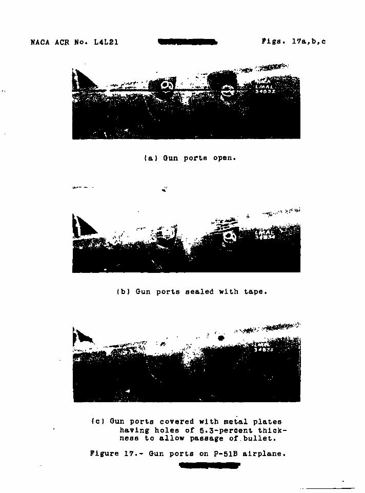
NACA ACR No. L4L21 Pigs. 17a,b,c
(a) Gun ports open.
<< -<n
(b) Gun ports sealed with tape,
(c) Gun ports covered with metal plates having holes of 5.3-percent thick- ness to allow passage of.bullet.
Figure 17.- Gun ports on P-51B airplane.

55 > > > o PO
as o
N
.002 Ci
Q
C< Q)
•H Ü i
•H «a
v B o a o u i a bo a aJ -H h Q
.001
W TONAL QQMMf TEE FORl
umsoRvj AERONAIDCS
Gun ports unsealed Gun ports covered with tape, tape torn 0.053t diajD. hole In gun cover plate
Airplane lift coefficient, CL
Figure 18>- Drag increments of several gun-port Installations on P-5IB airplane in Langley full-scale tunnel. R * 6.5 X 10⁶'
00

as >
>
> o
as o
/* /im.
Motnttof p»st fbirlnq eh O.ötSa »xttnate* ofify
-fOfc -373c-
r- r-
MTIONN. MMSORY COMMITTEE FOR «BOKMmCS
Figure 19.- Machine-gun extensions on XF2A-2 airplane. a - 0.026c or 0.005c; 0.254c gun extension not shown.
"9
oq
O

Gun extension
o 0.028c + -139c X .139c a »254c
Height above chord line
0.026c • 026c • 005C • 005C
.OOIH— o
Q •P P G < <0
•H O •>
«H +» «M C
0) S O V 0 u 1 Ü
ÖO ö d -H b Q
.002
95 > > > o so as o
tr
w
0 .1 .2
Airplane lift coefficient, CL
Figure 20-- Drag increments of machine-gun installations on XF2A-2 airplane in Langley full-scale tunnel. R = 5.5 X 10⁶.
«I
N o

NACA ACR No. L4L21 Fig. 21
\ \Q-*/»c **»•
7//Ja—M
k**fc»
-./com—* . <»-#->- «M* /*» SKefJon 4-A
COMMITTEE FOR AEROKMmCI
Figure 21.- Machine-gun Installation on nodel of modified XP-41 airplane.

NACA ACR No. L4L21 Fig. 22
Figure 22.- Service gun fairings on F6F-3 airplane.

.001
V Q
«3 c 0) e 0) Li O C
•a c 0) •H O
•H 4-1 «M 0) O Ü I bo a)
Q
(a) service gun fairings on F6F-3 airplane in Langley full- scale tunnel. R = 8.0 X 10⁶.
•5 .OOU
.002
/^
1 mLu. tAnxm 1 IMMHnfEm«3IMWITK
<Sjp£=5
" T T 1 f Y -.2 -.1 0 .1 .2
Airplane lift coefficient, CL
.k
(b) Machine-gun installations on model of modified XP-41 airplane in Langley 19-foot pressure tunnel. R = 6.2 X 10°.
Figure 23.- Drag increments of two machine-gun installations.
as > > > o 50
as o
r-
r* w
o
w

JMc- -FF
as > es > > n a
'as o
N
-/f/fc-
»mc»o*i>Urti\
"4C4 £6tU3)-tMfa>*a,£
NM10ML MMSORf GOHWIEEFORABOIMUICS
... I. ..u.tM « chord 11M of „odel of ^ of ip_M ^^

NMKMM. MMSOOT COMMITTEE FOR AQOiAUTES
> O > > w
O
f CO
(b) Machine-gun mount on model of XP-63 wing and on P-63A alrpl&ne.
Figure 24.- Concluded.
•»9 I—
N ilk

NACA ACR No. L4L21 Pigs. 25a,b
o o
3 a
Li el e
c
ai o u I to
a
.000
.001».
o Unsealed installation + s ealed Installation
.\.
» ^Hfe- N y r t f
(a) Drag increments of gun installation on P-63A airplane in Langley full-scale tunnel. R - 6.4 X 10⁶.
.002
.001
-.«• -.2 0 .2 .k .6 .8
Section lift coefficient, Cj, and airplane lift coefficient, CL
(b) Drag increments of two gun installations on model of wing of XP-63 airplane in Langley two-dimensional low-turbulence pressure tunnel. R - 6.0 X 10°.
Figure 85.- Drag increments of machine-gun Installations on model of wing of XP-63 airplane and on P-63A airplane.

I -*/7c
j>r/o
MM* KKjrammMC* LINK.
_ _AIRFDtL CONTOUR _ -
T
syttmnucti. #/r» HKSMCT- 70 cMAmt* u*ms
as > > > o
SB O
w
MTMUL «HURT comrnLH»f£sama
Figure 26<- Machine-gun mount on model of XA-26 airplane. aq
to 0»

as > • > o S3
2 O
r-
c to
Airplane lift coefficient, CL
Figure 27•- Drag increments of gun installation on model of XA-26 airplane in Langley 19-foot pressure tunnel. R = 3.6 X 10*.
•=9 I—
N

NACA ACR No. L4L21 Pigs. 28a,b
(a) View of projecting gun in unfaired condition with submerged gun removed.
(b) View of fairing 1 on submerged gun and Grumman fairing on projecting gun. Both fairings provide space around gun barrel for cooling air.
Figure 28.- Gun fairings on P4F-3 airplane. (Prom reference 6.)

NACA ACR No. L4L21 Figs. 28c,d
(c) View of fairing- 2 (wide) on submerged gun and Grumman fairing on projecting gun. Both fairings provide space around gun barrel for cooling air.
(d) View of fairing 3 (narrow) on submerged gun and Grumman fairing on projecting gun. Both fairings provide space around gun barrel for cooling air.
Figure 28.- Continued.

NACA ACR No. L4L21 Figs. 28e,f
(e) View of submerged gun in unfaired condition and projecting gun with Grumman fairing. Rubber grommets installed around edges of fairing and wing opening.
(f) View of faired wing opening for sub- merged gun and Grumman fairing on projecting gun. Both fairings pro- vide space around gun barrels for cooling air.
Figure 28.- Concluded.

NACA ACR No. L4L21 Pigs. 29a,b
DIN£NStON 9.\b{c\J\B\f\o\J»\ CMHoNmumtm 1 CAMMr/BVR/N+1
(a) UnderBlung cannon Installation.
NATIONAL tatotm COMMITTEE FOR ABOWJTO
(b) Submerged cannon Installation.
Figure 20*- Wing-cannon installation on XFSA-2 airplane.

.008
.006
o Q O
3 .oofc o «
£ G 0) 5
0)
U c bo
H Li Q
5 .002
0 Fairing l, undersxung + pairing 2, underslung
Submerged
0 .1 .2
Airplane lift coefficient, CL
Figure 30.- Cannon drag Increments on XF2A-2 airplane in Langley full-scale tunnel. R = 5.5 X 10⁶.
>
>
> o w ae o
t- *>• t-1
N
•=9
oq
O

SB > > > o W
58 o
M
KXKSßZK gjg/^" 65,3-4/8 66flUSh2/6
Z4 Z4 VIS 36 36
CANNON D/MEfiS/OHS Cpercmt c ) ~5 6 a.
T7W !S9f '.888 (.458
7*4*
135B1Z38
II30ZJ16 3.970 G6£f 9.8BO T£t5 6^¥i
r4'\tS9JV*88 V4JSU 17to42fM*to\u*te546
0 ,
7393T8951458 3.970 0.6299*60 6Z65I6JI&
& m 7945 6.//Ö TZU A3.436 &¥% VFM
£<I •£*
NATUML MNSORV COMHITIEEFORMnMUnCS
Figure 31.- Twenty-millimeter cannon Installations on low-drag and conventional airfoil sections.
w

NACA ACR No. L4L21 Figs. 32a,b
NACA airfoil section o 66(2151-216 + 66,3-418-. X 88010
.1 .2 .3 -k Section lift coefficient, ct
(a) Drag Increments of cannon on three NACA airfoil sections.
O Rough spot + Cannon extension 0.165c x Cannon extension 0.541c • 5 cannon extended 0.165c
u •» a CO
a ° 5 H 0 |) U Li 1 u bo a b a
.002
.001 —fc =—H ^ ^ N ̂
i
i= =-* i— —( i - 4 >
^ i
M OOMIUT
tow. i IE FOR
•MOW UDMUI IKS
.1 .2 .5 .If Section lift coefficient, Cj
.5 .6
(b) Drag Increment of two cannon extensions compared with drag Increment of rough spot on NACA 66(216)-216 airfoil section.
Figure 32.- Twenty-millimeter cannon Installations In Langlej two-dimensional low-turbulence pressure tunnel. R - 6.0 X 10⁶.

« A FAtfUNG B
as > > > 50
o
ro
WßOARD Nfl»MLMMSOff
CWVnSFORABDMimB
OUTBOARD
figure S3.- cannon Installations on XP14C-2 airplane. oq
OJ W

> > > o SJ
2! O
r-
Flfun S4.- Cannon initillitlons OB »dal 01 XF6F »lrpl«n«.
•=9
W ilk

>
>
> o pa
rzrj
1
LONG FAIR/NG-'
.294c
• FAIRINS-1 SHORT FAIRING^
r-
r* to
(a) INBOARD CANNON.
Figure SB-- Cannon installation! on aodal of IMU-1 airplana.
oq
en P

SS > > >
O
N
0^ OUTBOARD CANNON, MHOML MMmr ooNMnEEmiaoHuni
Figure 35.- Concluded.
«1
C7I

NACA ACR No. L4L21
.002
Figs. 36a,b,c
o fairing A + Fairing B
.001
(a) cannon installations on model of XF14C-2 airplane In Langley 19-foot pressure tunnel. R - B.B X 106.
o a
*» u c <s 0) -H o •> —I •> •" a *-• i) « B 0 « u u 1 o bo c •J-H u o
.002-
.001
o Unfa1rod cannon + Short fairings * Long fairings
(b) Cannon on model of XF4U-1 airplane in Langley 10-foot pressure tunnel. R - 2.75 X 10B.
002 r
o Unfaired cannon + Rounded fairings x Razorback fairings
.001 -
0 .1 .2 .3
Airplane lift coefficient, CL
Installations on model ol Langley 19-foot pressure tunnel-
Figure 36.- Drag increments of sereral SO-milllneter cannon Installations.
(c) cannon Installations on model of XF6F airplane In )1. R - 6.16 X 10⁶.

NACA ACR No. L4L21 Figs. 37a,b
M&C —
(a) Short fairings and cannon.
NATIONAL ADVISORY COMMUTE FO« AEJWWJTCS
(b) Long fairings and cannon.
Figure 37-- Cannon and fairing installations on model of wing of XA-41 airplane. Cannon are centered 0.006c and 0.010c above chord line. Pairings are circular in cross section.

.OCfcr—
o Q U <
B
a u u c
• 002
Remarks Shields BhleldB Short fairings Long fairings
as > > > o w as o
c-
r- w
(a) Cannon without air flow.
4> a
• o u i to •) u a
.0*1-
.002
Symbol Position
0.006c and 0.010c abore 0.005c and 0.010c above 0.006c and 0.010c above 0.005c and 0.010c above
chord chord chord chord
*o 0.S7 .SO .SO .57
Remarks
Bare cannon Bare cannon • Bnort fairings Long fairings
AMsnv «on wires I
.1 0 .1
Section lift coefficient, (b) Cannon with air flow.
.2
figure 88.- Several cannon installations on model of wing of XA-41 airplane in Ames 7- by 10-foot tunnel. R - 6.35 X 10⁶. Holes around cannon have 0.0S2c and 0.054c diameters.
oq a
03 P

as >
>
> C1 3J
9B O
ro
figure 89.- Cannon installation on P-5IB airplane. •=9
oq
Oi

o a
a < a>
O •« •H •*
4-1 V 0) B O V a i* i o bo C aJ -H ki a
• OOli
.002
-?2
^ ^^ "^viti^^^^^
^^^^^^^^S^^^^
NAIKJIAL ADV »Iff
OOiMITTEEFORAEiONMnK
-.1 .1 .2 .1*
Airplane lift coefficient, CL
Figure 40.- Drag Increments of cannon on P-51B airplane in Langley full-scale tunnel. R = 6.0 X 10.
as >
>
>
as o
10
«1
o

as >
>
> o to
as o
c ilk r1
ro
oq

NACA ACR No. L4L21 Pig. 42
Figure 42.- Twenty-millimeter cannon mock- up on F6F-3 airplane.

NACA ACR No. L4L21 Figs. 43a,b
.002
.001
o a u
c « a • u u c
-J-^r^n =9= =9
(a) Cannon Installation« on F6F-3 airplane In Langley full-scale tunnel. R - 8.0 X 10⁶C»PProx}.
a
w o Ü
BD cd
a
.002
.001
-.1
>
C01IMITTEE NATION L ADWJ6V
Ti^Rj nCN HHWlMtfiM
0 .1 .2 .3
Airplane lift coefficienti CL
.k
(b) cannon on F4U-1 airplane in Langley full-scale tunnel. R - 7.6 X 10B.
figure 45.- Drag increments of several 20-niUlneter cannon installations.

TITLE: Summary of Data Relating to the affects of Wing Machlne-Gun and Cannon Instal- lations on the Aerodynamic Characteristics of Airplanes
AUTHORS): Qulnn, John B. ORIGINATING AGENCY: National Advisory Committee for Aeronautics, Washington, D. C. PUBLISHED OY:
OTO- 7722
oaw. ur-rt HO- ACR-L4LS1 PtCUSMKa AOSCCT KO.
can Jan'45 Unclass. U.S. Eng.
EUB3I3AIHK3 photos, tables, dlagra, graphs
ABSTRACT:
Analyses of test data show that a well-designed gun port should have little or no effect on the drag or maximum lift of an airplane. Smallest drag-coefficient increments for protruding-machine-gun installations wore obtained with guns protruding about 4 percent of the wing chord ahead of the leading edge located on or near the chord lines and faired Into the wing contour. Fairing of cannon located on the wing and providing air flow, decreased drag-coefficient Increments about 0.0003. These had little or no effect on the maximum lift
DISTRIBUTION: Request copies of this report only from Originating Agency DIVISION: Aerodynamics (2) SECTION: Performance (2)
ATI SHEET NO.: R-J-2-10
SUBJECT HEADINGS: Drag, Aerodynamic - Protuberances (31290); Airplanes - Lift characteristics (06470.65)
Air Daarjrjoat* Dhrbloa, (atafllfjcaca Air Hatoriol '
am TGCKMicai INDIH Wright-. atterKKl Air Forco Baso Dayton, Ohio

raarosaoo (ereil?)
Qulnn, John H.
AUTHOMS)
c-a-7-6 ' ©gKiJCSEOTOAl!,
[DIVISION: Aerodynamics (2) • SECTION: Parasitic Components and Interferences (7) (CROSS REFERENCES: Guns - Drag measurements (47450.6).,-. 1 Interference effects - Aerodynamics (525C1) '\/\
yDH" 16199 IORIG. AGENCY NUASD'
l^tON
AMER. TITLE: Summary of data relating to the effects of wing machine gun and cannon installations on the aerodynamic characteristics of airplanes
FORG'N. TITLE:
ORIGINATING AGENCY:National Advisory Committee for Aeronautics, Washington, D. C. TRANSLATION:
1LLUS. I FEATURES
57 I photos.tables»diagrs.graphs COUNTRY
U.S. LANGUAGE
Eng. IFORG'I NCIASQ U. SriASS.1 DATE
Confd'l |jul'44 PAGES
84 ßBOTACT
Collected data obtained from test? of moddls and airplanes are presented and analyzed. Results show that a well designed gun port should have little or no effect on either the drag or maximum lift of an airplane. Gun ports having a small height, with air flow vents located on or slightly below the chord line, cause the smallest drag increments. Guns mounted below the wing cause high drags. Gun extensions of at least one-quarter chord have less adverse affect on maximum lift than the shorter extensions. Fairing cannon into the wing and providing, air flow substantially decrease drag.
NOTE: Requests for copies of this report must be addressed toi M.A.C.A.. Washington
2\lR TECHNICAL DNBEX SQNFOBEMVOßil
T-2, HQ., AIR MATERIEL COMMAND
J-
WRIGHT FIELD. OHIO, USAAF WF-O-ll MAD 47 M£l

UNCLASSITlSiä) PEP. AUTHORITY« IftOSX OF MCA raeiIHKAL PUBLICATIONS' " BATED 31 UF^'B^BER 1947 «