Embed Size (px)
Citation preview
12
CHAPTER 2
STRUCTURALANALYSIS o|= WARSHIPS
2.1 Introduction.
Warships have totally different functions to perform during operations than
other vessels like merchant ships. Warships are thin and longwith a high Froude
number, designed for intensive loadings like explosion and blast. Linear elastic
analysis method conducted for the determination of displacements and stresses
will not be sufficient for realistic and acceptable estimation of the strength of the
warships. Nonlinear analysis (both geometric and material) has beenrecommended for such structures. Owing to the presence of uncertainties in
material and geometric features, there is sufficient scope for reliability analysis.
For all these analyses, finite element method is considered the essential tool and
recommended. Structural modeling of warships, description of the design loads,
finite element analysis, ultimate strength analysis and reliability analysis of
warships are described under the following subheadings.
2.2 Approximations in Structural Levels of Ships
The action effect levels of ship structure has been described in different
sources in different ways. The Primary, secondaiy and tertiary bending of the
hull and resulting stresses (01,052 and 03) are depicted in fig 2.1. The primary,
secondary and tertiary structures, as defined by ISO Report ISO/CD 18072-2 [18]
are identified as indicated in table 2.1.

'|d
-X *7 7 mmwmnm 7’ ’ ’ “‘m'“" J T"" 7 ~‘i~;,i;':
\_..$
'€>u{l‘i5-0_1.0§, V ~__ I"'..;_'_"T"" — ~ ~~i1i_1~- ——— _.‘K I **" T Q1:3"“:\A? -4-1 1“ 3 ";_:_“"'P'_, "“"""‘5"' """""'7“5» ..__<, ---> -----.
e i i ~P ....a --. .... -.. .- -a -- _ .-- -a—,:=_-§- ~ ;—Z ‘r -P:-"**" ‘I""‘$v~.tvt\"u'_ B3132 3
kt A g C0l1\biflQi $5-Qircwtf§.Qhdl;~l"sg _‘Z?"r"!.U
’O[a1l“£ $i:‘r‘*?1£-I
Fig 2.1 - Primary, secondary and tertiary hull bending [13]
Characteristics Primary Structure Secondary Tertiary StructureStructure
Loading In-plane _g Norma|W__ NormalStresses Tension, Bending and Bending, Shear
1 Compression and Shear , and MembranelShear lExamples Hull shell, deck, Stiffeners on T Unstiffened shell
bulkhead, tanktop bulkhead“, shellBoundaries l Undetermined Primary structure Secondary?_ Structure
Table 2.1 - Classification of Ship Structure [18]
2.3 Structural Modelling
Structural modeling based on different levels of geometric idealisations
has been an accepted procedure and has been well utilsed for ship structural
analysis from the beginning of the history of strength of ships. A one dimensional
beam model for the longitudinal strength estimation, a two dimensional portal
frame for transverse strength estimation etc.,. can easily be cited as examples

'l4
However, the most ideal structural model for a ship will be the one in which the
entire ship with the inclusion of all minor details like stiffeners and structural
discontinuities and subjected to a realistic load combination. This is possible only
with the support of advanced computing and will be a costly and time-consuming
affair. Often, the naval architect is not interested in the absolute values of the
response like stresses and displacements, but interested in the range ofresponse values, mainly due to the uncertainties involved in all the stages of
structural performance. In this context, it will be the most appropriate to take
steps for a realistic solution by analysing a representative part of the ship with
appropriate boundary conditions and actual loads, instead of modeling the entire
hull. Analysis of part of the structure bounded by main transverse bulkheads can
be quoted as an example. Such an attempt of selection of a structural identity of
a smaller proportion that will represent the behaviour of the hull will reduce the
effort in computation. This can be achieved by the logical and rational selection
of ‘critical segments’ of the hull girder/module. The procedure and criteria for
selection of critical segments and hull modules have been thoroughly discussed
[Hughes]. Global structure model and the hull module model for the finite element
analysis of the ship structure have been presented [ISO]. A slice of any ship
cross section between two adjacent transverse frames is widely taken as the
extent of the progressive collapse analysis [Paik, 2005].
2.4 Design Loads
The seaway loads on a hull have been classified as global loads which act
on the hull girder and local loads which have a localized effect and act only on
certain parts of it. Depending on the time domain description, loads can further
be classified as static and dynamic and this classification is valid for each of the
local and global categories [8]. The general global loads acting on the hull
comprises of bending moments arising from still water loads and thermal loads.
Low frequency wave induced loads like vertical and horizontal bending and
torsional moments and high frequency springing and slamming loads are also

TD
treated as global loads. Major constituents of the local loads are external static
still water loads, external hydrodynamic pressure due to waves, cargo inertial
loads due to vessel accelerations and Internal liquid sloshing loads [Jensen].
Fatigue is fast emerging as a failure mode of ship structures and therefore needs
special consideration in the ship structural design.
Wave loads which are the major seaway loads are random in nature
and hence probabilistic representations are critical for them. Procedures of
extrapolation of these loads to their extreme lifetime values are being
exercised. Generally, these loads are dynamic and random and theircombinations require the difficult but important analyses for determining the
degree of correlation between the individual components. These analyses
may be carried out either in a frequency domain or time domain.
Warships are expected to operate in a combat environment and certain
loads in this regard have to be considered for their design unlike other ships.The main combat loads to be taken into consideration are underwater
explosions/shock, nuclear air blast loading and own weapons effects. The
design loads used in ship structural analysis have been discussed under the
subheadings of global and local loads subsequently.
2.4.1 Global Loads
In the ship structural design practice, both hydrostatic and self-weight
loads can be determined for a given ship condition with a high degree ofconfidence. The underwater shape of the hull is readily determined from detailed
knowledge of the hull offsets and appendages, enabling the buoyancydistribution to be calculated. While buoyancy distribution is known from an early
stage of the ship design, accurate weight distribution is defined only at the end of
construction. Statistical formulations calibrated on similar ships can be used in
the design development to provide an approximate quantification of weight items

16
and their longitudinal distribution on board. The resulting approximated weight
distribution, together with the buoyancy distribution, allows computation of shear
and bending moment in the still water condition by successive integration. This
bending moment is always referred as the Still Water Bending Moment (SWBM).
The evaluation of wave generated hydrodynamic loads, however, is less
reliable than the static loads and there is less guidance as to how to handle the
dynamic nature of the loading as well as transient effects such as slamming and
sloshing. Nonlinear theories and three-dimensional load prediction methods have
been introduced but these require greater computational effort and have not yet
proven to be significantly more accurate than the two dimensional methods,
regarding the design considerations.
The evaluation of wave-induced loads is attained in many practical
situations through the quasi-static wave approach. The ship is positioned on a
frozen wave of given characteristics in a condition of equilibrium between weight
and static buoyancy. The scheme is analogous to the one described for still
water loads, with the difference that the waterline upper boundary of the
immersed part of the hull a curved surface. This procedure neglects all types of
dynamic effects and is rarely used to quantify wave loads. Sometimes, however,
the concept of equivalent static wave is adopted to associate a longitudinal
distribution of pressures to extreme wave loads derived from long termpredictions based on other methods.
Strip theory has been one of the first tools developed to calculate the
wave induced forces by treating the hull as a rigid body moving in irregularlydisturbed interface of fluid and air. The main drawback of this method is that it
considered only regular waves and it neglected the mutual interactions between
the various strips, which are of particular importance for certain frequency
ranges. However, regular wave loads can still be estimated using strip theory.

'|/
Panel methods, FE assisted methods etc.,. also can be utilized for estimating
loads due to regular waves.
The regular wave results can be extended to short-crested irregular seas,
by means of the superposition principle. The basic assumption is that both the
irregular waves and the ship short-term responses are stationary stochastic
processes. Long-term computations can be made using the spectral approach.
Available calculations for limited periods of time in specific irregular seaconditions can be translated to long-term predictions, covering the lifetime of a
ship or a fleet of ships. For each pair of values for wave height and period a
spectrum can be defined in terms of the spectral ordinates at discrete values of
the frequency, ua. In the absence of any actual spectra or observed wave heights
and periods, the only way to describe the sea is by means of the wind speed,
which can be considered to be the single most important factor in generating
waves. The globe is divided into various service areas by different agencies. The
classification by Lloyds Register of Shipping [42] has summarily been givenbelow.
Service Area 1 (SA1) covers ships having unrestricted world-wide
operation. SA2 is to cover ships designed to operate in tropical and temperate
regions, excluding operating in sea areas for which a SA1 notation is required
whereas SA3 is to cover ships designed to operate in tropical regions excluding
operating in sea areas for which a SA1 or SA2 notation is required. SA4 Service
Area covers ships designed to operate in Sheltered water, SAR Service Area
Restricted covers ships that are designed to operate in a predetermined and
contiguous area of operation. The environmental wave data for the variousservice areas are shown in Table 2.2 and the sea service areas are shown in fig2.2.

15
Service Area Wave Height for Mean Wave Extreme DesignNotation Service Area (m) Period (Sec) Wave Height (m)SA1 5.5 8.0 18.6SA; 4.0 7.0 13.5SA3 3.6 6.8 9.5SA4 2.5 6.0 6.0
SAR To be specially considered
Table 2.2 - Environmental Wave Data for Various Service Areas [42]
L L , <32 ~14-* r:::> =.V . ii . I : I '. . Y: IE V. _:"- \": : '1'. J’ .-:1 .::i§'.1':.:"' >1”. ’
Q . ~. Z , r 4 Q‘.. . A....a~.'¢:i.~'§fi-'..;z:=<.-‘- . ' *, ‘ . _ _ I‘ =3" ,° , “»- 2 $3. .¢.‘l'§ .,,»§rEi'§ ¢, 9. - ... . ~ V.-. ,< ._ , . . , 3*7"'4'-'11: -3} 3'17.“-‘ii:-: "“ iii-’§'~.-“é§'vTil ' ="E1~>$i*'5=' ' ‘ ‘ y » » y . . .. " *1‘ 6 l,- V. - . . .1... - ~ " * m .a. -Y- .1 I " -1:11. .:.1:-<.. -sr.-4..=.'--=-'-~-." -.1; \.'- _ l ‘= ":2 " ' -= -‘: 11.4: .‘ .. ' -._ ' 1*-' -. - ‘ ' '.' ‘v - Din - * ‘ <"1 .' “'-'-- ‘ Y-.0 51:" . ' 1»;-;:'7ii:1‘-'.¢§'<I.¢ié'1 --1 * - '2‘.-":':l.'-' -' ‘_3r.-- 1" " -. -43$";-:€\'7' .~'Z ..\7i '17‘: -cu - ' ~ ' 1-:bE1: '.f' 1'1 /‘ Ii "4 .".~.»¢.’.‘-'1 R ._ er-; -. fr-'1-3'.-:~.7§:~.:_-. . .-:-> 5.. -=. "-F3!‘-Y "'-1.~_§~-3-"'5:1-;-:.!:- Rea? .'>.?'..-:.-.+‘¢:;.$~.< ->' " - . ‘ ‘ A , 1 l. 1-.7-.\:-. .:' ' '~'~ I ' -- < 33 .,¢‘ ‘>-:;v1--' -1~'w.-311;" 1¢1<+.1.-'4"-=;*~¥¢ rt _-_*=I-' j;’§-_t;:‘-~3‘<§._'-I j"¥:-1."§>5~¢.'--¢¢»;---_‘:->- 4;"-2. ' In =‘ "-I ' 1 " 1-1.“--1.‘+l<1.¢< 's!<--4:;3€"§*»-.,;'_‘-- :»-;-‘:7
' . .. , 1»~ _ -_ ._ ‘,,_.;..4"¢-:3"-1: Z412‘6 W ~. " M" ,5I \_ \ I ::I%:§'§%:$1f.f2fj": I_ _I' ' II . ‘_ _' , _ ’. H . g,u, _ ;5._: t 5- w-.514 -- . .- . - .- l1 iv’ _ ‘ . 5:"- . - -._. ' >; '
‘I !
1~?"l
J‘
“\.~ g;3-\e.~v‘!\*§ut '1'!Q9%.
allF"
‘ll "'°' . Nix‘): § ,4 . {y>$"1¢.>.»a., ¢_ l{>._5i \.~'¢v _./3. ;.*»_§~‘W . :2. . .: ‘Q’-Iv‘ -'?t-f--'- - 1 .. -->.-;-- :<1"q'.;1r=~».I, 11;;-1:; : ;§'¢;<.'$_4;&é'=-‘§>§_.Z£:>-~ .-...--..Z~"'.~,~_.’»-"ua . Q 3 -, . , - ,.§ -:~',:-;-'1.» .';;‘~\;§~'-if= ~ 1% ":1 ‘E:-;¢=? 1' }. 51 ;_ .' 5é<';,-1,"'.1} .'1f.-=1»;--*_,1= j-.>-:;'=‘1--'l:5‘;IE-§,;ss:‘;;. .1‘. *- - 1...-531-:1; ;-;;.-;;.: 2. .. .1. ~s1;"11§:-2 . -V .5-: :: r .135». :--- . . 1 . . - »:1:'.'::"::':'.:::!..:..‘ . '1 I.:..: :1: -III .1-.If'.--.1 1"" - I ; _ - -"in ' 1...:-' ~ - -- ~ - < - * ~-1;. .- .1; .;.:~~;.9;-'-;‘1:"1. ;: ;:. '?I'*.f.-1, :>.".;.'-.1;.. " :t"~ '1-1*;-T5311 __ 5; , .3 "' 3;; _' " .:'~'§ ‘I. . _ <_ .:,~,’.r;;r_‘Ai; ’ "" " ' ‘ " ' ‘snag "NaE ’* "i ii;. ; .,...,.,..,.,. I A . i ;;;;,;,.__,;__.;~,, ,»;,;;_;-;_ ~. g ' _ ~_ , _-. _. 4, i ,“ bT7ta at ~ ; ‘ , “
Q...»
' "'€f'£~x °; K» §>;- ’§, Q ‘J ‘Qt ’§»§ ;.(a:3%:-.".rEr:x:-_g;».r‘:€3.vg.>:::>." .1.sgrs5~.§m- .'» 4 1. 1 -. -- 1':-\~° " ‘-‘="<:-‘.-21:"; '24 <-2;? ‘~ lit-1-11752;?‘ >1'.i1;=;:.:'-§.<$"-." V. .~‘.=4;»r 1;>I1.<;-‘f< 3xi".<€-='5e1-r'\.<-:§r-1+1-:¢::1:::>iz<=><:-=~¢r » >~.§?*»~*>*’-:<-»=~.~>’~=*5<-"-;;*1'5-i ‘=" -- l 13 __ € ;. ,.,.. ,. , 2,,_,, 3 t ,1 .\ .45 . .-. .<v 0* ._ .4 , . ; 1. -. ., \ ‘\\fl\( <w- qw .1. ,,.-$3,? ’>? ,$,;,.».¢ .u;;,.,.** ~;¢,§§. ,3 's.!2$“»i,2.s,‘€’» 4:; Al ~,;,..‘3Y~..» *:”.3_,,,,;.. fl - ~q$-<3’ 1 .: ,..;.3\g=: ** M . by if , >5: ~<;.
3-?‘1 """1'1'5.I1'5-'II:i .1‘ I -I. 351%": ii-5:. 3'13 5573 C-3='5?5';;;;"-fl .>$'i'»l5:’~l-3. -"E5 11:155. if. E. §:'f'.i¢='51 '-1'-I5 Iii :5:-'13-1111112: '1 .1 v:f"£Lr'-1""--3 ‘L " =1 -' if-Q 375- H ‘ 1‘ ' . 'ft_:_:j_;:':;.':_:j'j:_;l . 1' -.15 ' . I ' .I-I - ‘I 1'11? -'1; -.3 'QIlf.; 1-_ §- §.if3I§E§{'.;a': ':j I if :" ::f':':_.j§:§ "I "1 "":' .i'7 ? :':':'.?. 1'11 ': I} 51. ‘i ' -5_5_ - ;-5 ;3' ' ' ' 1 ' j - ---- - ':;_:'_: 3:4-t;.v \. _;_ . .:»>:+-;:- . .- -- '- :'_ .' ':.. .- . - - -- . _. -vr ._ .. .
~f?~z1 <=w..r. ~ e; ,»*”%'*3"= s~::‘$,€-"W" 1 'w‘*.*>"*I'° ”’ J"? ~... "'*""='“" - ~ 6 "Y » @< "K?" M "':'m'*" £3? ‘ '.§I‘.'::.\-:§J.\'ii: .I‘A§:‘u'I.\.’ ': _ 2571 7‘ I. -: :-.-1~.: .- g ~ : .- - . K5-' 4 ."-:1: '. . --:1‘ '&- ‘- I - . ’ ;1‘.I:,€.”-;I;5"i - :.-Q1 4: ¢!;i;1;I‘ 1" " .~~' ‘:1’! . . .‘ -. '.:-.I:.".'-2.I~‘§§ . ''.-. ~ 7'33‘, ' 1 £7. 1 '* '~ ~ W '~ ..: -': ‘f": " "1? :- ; '-.-;".'i . .1 j '_ j ‘ . .- U: .‘ ' Q 555».-5? ~'l;1~‘-- =15 11- ‘;Y';.;-‘-". '4.’ ‘.:- ."~ "*"y:‘I 1. $1": :4 .‘I' .- "'?!' 'l5:2'}I:= 1"?! 3<§':»‘I"' 1' 3- "-5-, “ ~;-' ' . :_ - _ °" .‘ : "', ,'~r~'""~':'-'\'~r':‘<- 3 -w-ax mu”? Mwv .
1?-e
.-I its
. . .. 3. . . 4. u’:i.:l'?t"‘\"?::I:-N3" :7‘.-"J"-' . :1‘ i:’-1':-'51‘ if-<'»'3.'l:?:l£l! *1."-*.1.' 1' -. :1:'- i:i ‘-?’.§3""- ; ‘I ' .-:"‘?";1‘.<:F;T;¥"‘:=§1.% Li:':l‘§‘.~"‘:7:?!ti\' '75. ": 75'“':?*1.":1.;:I:i'2».‘?1:l‘v'.' rl .2" .~‘.?:'.:-‘.l".1":‘ 11:11:-1-"f-‘.i"1 "‘¥-":‘Is'!'~?'I‘¢','.:.<~?;‘:"£>:'4'I~;¢;‘-'-Y? f;,;'-W?f"\l;7;1:-;:‘-5*-$§f¢~*5;:-*»‘»'¢~‘-‘~' r;'-q:-*-;';7‘_<§3+ 952'-;.--;‘.;.i-;*$51;.t-';$ < 1:" _'_\_';".\1g;;1 .> :;'._ |'.'>,'.. : .. :;-.. ’~; tr-'*?ré?-es'¢.--.T=’»Y3s§.Y-1 5,112’-e=~ i¢§§:'~’~"¥»:'=1k'+.'»' "i.if?»4:&>§\¥~i#;%:=I';2e:=:k¥= -"’~.¢?~i' '*“- '-..-*¢ 2..-’».?*-3" ""‘ =‘l . . ‘ -,. -‘1’. £19‘; ,1: ét (;. 4;; . . ‘lg?-;; -fl}-$_’§,-_:-,_-;.;;;;‘,;_ . , '&{_>;t~.;,;._\_.-:;._§;1 . . ;.,- g » . , '_ “V. . .. ' i V _ . ‘£¢.l,_§§' j _ _, . 1 '>_’;$_ fiiiiii-,,g§;; _» - 9;; fi,¢‘-_;S_{.¢.F_.;v:;:-___ '5 pf , -V,‘ ‘ 5» 3‘ _ L _~ _ ; g3 , .§f ;}-e'v.§{‘¢:>!-:<§:- ,;:<€;».r~£¢;,;§._.-5-13$;-..~;:¢:*‘¢'x-<$*:<mM;»:t‘.‘:<»;$$-=:.s 5:'$;.4i.\ '4-.;-¢;3.;k(.»<'>§o:-§:-11-;»:E¢->2-fés;:§';; -3‘,-, -.,, -- -“-;>"{Q"’i?;?"“‘-'~"" ' < 1' ‘- ' '4 1-at-" ii’ "' r 1 -- 1.;-' ' " '1 -' ‘ ' '-‘3 '1'1!i?" . .' 'i .1. <5. --"'-1 .7 ‘: -; : ': J’ ':A".' "1-:":F:i:l 1:'.3.:l:'.3 :1’:-‘.'I'-1 ":'v.'1 .' ‘ . .-."":3:3 '$:~,T. . " -< '3 " ; -' "' "" " ' -' ' ' - ' :- ; ' . ' ‘ .' .'1 .1 ;» . -'__4M!:>.' ‘T!-9!
=33-;" i"iv.z~i~;;?%;:5=.¥&-;L ~ .2" .i:I3‘i:"?-.¢:',3:7';-17‘ - ‘3-':r.1'.".':3: ‘ .1 <,0 _.
n,\-in-..i
Fig 2.2 — Sea Service Areas indicated by Lloyds Register of Shipping [42]
2.4.2 Local Loads
Local loads consist of external (still water loads, low frequency dynamic
pressure and slamming loads) and internal loads (inertia forces of cargoassociated with accelerations, sloshing of liquid cargo etc.,.). Fatigue loads are
important in the design of local details, which require estimation of stress ranges
G
and number of cycles during the ship life. Internal loads and fatigue have been
omitted from the purview of the present study.
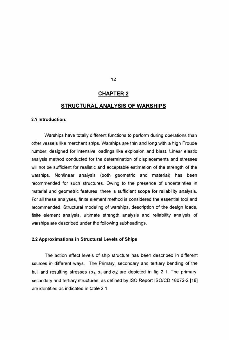
The other major local loads are due to equipment, cargo, crash loads (like
helicopter crash, vehicles/crane), ice, flooding, docking and pressures on the
shell envelope above as represented in fig 2.3.pl“, /\_\ -"Tm
. i\\‘_g//‘\\\‘F’“dwq, F‘ ,- “‘~~_‘.2 U ' \'o J 1 \\\‘\/' ~\/‘\I\\\_ _. .. \~I<‘\\ I .1 /"W-xx II \\ \. c_¥<§(\\ \\_¥, \_\i\\. - \\__;,/ \\ ‘K "~>‘
fl//I /7+. 47.5
55 5°
.'\, ,/ ' _\. , \l.\__’\:\,i£,/~ ~~ ' s ~ ~/~\"~.\ _\
/ .
\x\/__,_
Fig 2.3 - Pressures on the Shell Envelope above Water [42]
For the global structure level analysis, various conditions of standard hull
girder actions (e.g., vertical still water bending, vertical wave-induced bending,
horizontal bending, wave induced torsion) and their combinations are to be
considered in compliance with the guidelines or requirements specified by
classification societies. Ballast water or cargoes are distributed into thecorresponding nodal points using mass elements. Local pressure distribution of
the tanks may not be considered for the global structure level analysis. Static and
hydrodynamic external water pressure loads are applied to the external plate
shell elements which form the envelope of the ship hull.
The magnitude of pressure actions on the transverse bulkheads arecalculated for the worst cases. These pressure actions are applied as equivalentnodal forces at the related nodes. The sectional forces and moments will also be
applied at both ends of the cargo hold model. Once the sectional forces and
moments at the left end of the model are specified, the corresponding sectional

LU
forces and moments at the right end of the model may be determined to satisfy
the equilibrium.
A set of the sectional forces and moments are selected from those
obtained for various load application, operating conditions and sea states, which
give maximum hogging and sagging moments in the cargo hold area andmaximum shearing forces at the bulkhead locations.
2.5 Rule Book Based Structural Analysis and Design of Warships
2.5.1 Introduction
Naval Engineering Standards (NES) have been in use for validating the
various aspects of design including structural design. NES 154 [30], titled ‘Design
Standards for Surface Ships’ defines the structural strength standards in the
design, construction and modification of surface warships. It provides a standard
against which ships’ structural designs are to be judged and approved.
Introduction of classification society rules in warship design is one of the
latest developments, and the first set of draft rules were published by the Lloyd’s
Register of Shipping in 1999. The main objective of introducing a military arm is
to co-operate in areas related to the effectiveness and safe operation of naval
ships. Of late, the Indian Register of Shipping also have brought out their own
rules. The rules provide a staring point for structural design so that the designer
does not have to resort to design from first principles.
2.5.2 Structural Analysis of Ships using Naval Engineering Standards
2.5.2.1 Longitudinal Strength
The criteria put forward by NES on longitudinal strength is that the
hogging and sagging design loads due to wave action on the hull at any point

£'l
along the length of the ship should not exceed the strength at that section
throughout the life of the ship. The design load is defined as that vertical
bending moment and shear force (both hogging and sagging) that have a 1%
probability of exceedance in the life of the ship allowing for weight growth over
that period.
The ultimate strength of the hull is defined as the maximum bending
moment (both hogging and sagging) that the structure can withstand at any
section before collapse. Buckling and plasticity are also to be taken into account.
The ultimate strength can be defined as the point in both hogging and sagging
where no further longitudinal bending moment can be sustained by the structure
for any increase in hull curvature.
The calculation of design loads should consider the sea areas in which
the ship is expected to operate, the duration of operation in each area and the
expected operating conditions in terms of speeds and headings in different
sea states, as mentioned in section 2.4.1. The design loads and theirlengthwise distribution along the ship includes an allowance for slamming
effects and the effects of the design wave traveling along the hull, asindicated in fig 2.4 and 2.5
,_,-\.,.,- . _-. . ._ . _. ./'P “"'~. 1".U ‘*~ i, ./ “~ ' '\I \ 1. 2.DEMGN uuomo uoutm osnmfliou ._--.--.-+7’ Q \ K-. _.--I"--' ;'--*-'-~'--'-w \‘._“_ I’/I \ \ _
/ I ‘I "2i / “some M . ~/ ; “. HOGGING - .0 ‘ ' '______ __.i.._____________ --44--‘---I
._\\ \\\\:\\\\
/ /’// _ “l
_T\ 5
\~_\;
__¥,_
l
“\\ ._ |\‘.\\ ,\_' \ 1L/ \“=‘\"J' ' *— ~ W * ’- ~——* **»* ' *“—+""*' '"'"*I 1 I 1 rr " ' 1 ¢ 4 —¢ a W K l '"II IQ I’ ll 97 1‘ U Z 14 3 ’STEIN QowFig 2.4 Distribution of Design Vertical Bending Moments [30]
-=~.-
as
nt
Bl1
6.1
O
C
Q
Q
IF

ZZ
Design Shear Force ,'9____,_.’___- , ._*,_-""'.~ I’ 'Q-I"-’\ "Aw". -'\o--9 ' .'___./- ,-_,<-rll ¢_.-- 1__,.-_s;;;_'._ ,l_ I.\- I,~ x1 SF envelope of '_,-" 'labsolute Value i,, H fl "I'- r -., ,1' xi. r‘ "\_ '/ '\_ I-' 5|'\' I \1.‘ I)I \, ;'I \ | _’ \. 2 \..1 ‘ I K.’ \ |' ' '31 20 19 1 fiaft,’-I--2-,_~~.i_ - : . IT-.".: ._.—.;:?'~. .__*;~_*;::; <1;-t<:;'~'-'-~~;~~ ~- -I‘ " :.-:;.:...-. :’.;_,::._._. _~:;i::i;r.:_;:.._i__ fi__ll 17 I6 I5 ll I3 I1 E IO 9 I 7 G S O 3 2 1
Fig 2.5 Distribution of Design Vertical Shear Force [30]
2.5.2.2 Local In-Plane Strength
In addition to the requirement for the strength of the hull girder, there is
also a requirement for strength of individual panels within the hull to resist in
plane loads due to longitudinal bending stipulated by NES. A panel is defined as
a section of stiffened plate between horizontal and vertical stiff supports, usually
decks and bulkheads but sometimes deep stiffeners as well. The stress in any
part of a panel should be calculated assuming the design bending moment, and
using simple beam theory taking account only of effective longitudinal structural
material in estimating the section modulus. Effective longitudinal material in this
context is defined as any structure with a longitudinal extent of more than 10% of
the ship’s overall length. Shear lag and other effects, which reduce the load
carrying efficiency of the structure, are to be accounted for by means of effective
breadth. The elasto-plastic collapse stress of each plate-stiffener combination
also is to be estimated on similar lines with effects of buckling, plasticity, as-built
imperfections and residual stresses etc.,. incorporated. The collapse stress is to
be at least 10% higher than the applied stress except where lateral pressure is
applied in combination with in-plane loads. The overall collapse stress of the

LO
grillage is to be estimated using orthotropic plate theory or finite element analysis
and is to be at least 25% higher than the applied stress.
2.5.2.3 Transverse Strength
Transverse strength of the hull is its ability to withstand the effects of
hydrostatic and hydrodynamic pressure. The loads to be applied, which allow for
the effects of ship motions (not slamming or green seas) are taken as static
heads of sea water as illustrated in fig 2.6.
Design Relative Motion _,.»~"'”'..1‘
i~ 11' L
___ _ ‘Seep WaterlineT¢Draught Amidshipst . r.,.= vr=-mi
at Fun Porpmilicular
~¢( EL:-n—.i1.
i:@
-‘L-‘ 4-0Ihl"'°
gmFwk/
Note: L (overall lengthl is in metres T IX . .__ E , ._ Sm Minimum HadSm Mmnum Hud ' \C1 §0- 3 /L " '/LDnp Waterline
l‘""iii,,..-.»n; *'Aftlr Settion Forward Section
Fig 2.6 - Hydrostatic Heads for the Design of the Bottom and Sides [30]
2.5.2.4 Shear Strength
Shear stresses on the hull are to be calculated using conventional beam
bending theory. Shear forces are assumed to act in conjunction with bendingmoments abaft a section O.35L forward of the stern. At all other sections shear
forces and bending moments are assumed to act independently. ln the forward
half of the hull the allowance applied for the effect of slamming on bendingmoments can be assumed to take care of the combined effects of shear force
and bending moment.

.44
2.5.2.5 Torsion
Torsion analysis is required for ships with large deck openings, unusual
form, proportions, special operating modes.
2.5.2.6 Permissible Stresses
NES 154 prescribes that the maximum tensile or compressive
stress at any point in the grillage structure must not exceed 83% of the yield
stress of the material. The shear stress limit is 50% of the shear yield stress.
When shear force is applied independently, the applied shear stress (rd) is to be
less than the critical elastic shear buckling stress of the plate panel between
stiffeners, and of the critical elastic shear buckling stress (tSc)0f the combination
of plate and the smaller of the stiffener sets on the plate. lf shear stress is applied
in conjunction with in-plane loads due to hull vertical bending, the safety factor
between total compressive stress (in-plane plus local bending) and the average
in-plane collapse stress of each plate-stiffener combination is not to be less than
‘2==»"ll‘2;<=_‘2@‘ils. The shear stresses resulting from torsional loads on the hull due to
wave effects are not to exceed 50% of the shear yield stress of the hull material.
2.5.3 Structural DesignIAnalysis using LRS Rules
The rules apply to ships of normal form, proportions and speed. Although
the rules are for steel ships of all welded construction, other materials for use in
the construction also will be considered such as use of special materials at select
locations, use of cast/forged parts etc.,. Scantlings are generally based on the
strength required to withstand loads imposed by the sea, payload, ballast, fuel
and other operational loads. The design loads and pressures are defined in the
rules. Direct calculation methods to derive scantlings based on maximum
allowable stress or other suitable strength criteria also can be used.

Z0
Static loads are based on standard conditions. Dynamic loadings are
examined for both the local and global structures. Wave induced loads are
considered both in the static condition (hydrostatic and pitching pressures), and
in the dynamic mode (impact, slamming and hogging and sagging wave loading
conditions). lt is pertinent that the factors of safety applied in these calculations
are not explicitly mentioned.
The rules are formulated to provide for scantling derivation for designs
comprising the following structural framing systems.
(a) Primary/secondary stiffener systems. Due to the relative differences in
stiffness of the members, the secondary members are considered to act
independent of, and are supported by, the primary members.
(b) Grillage systems. The relative stiffness of the orthogonal stiffening is
similar and work together to support the applied loads. The grillage system
is in turn supported by major structural members such as bulkheads ordecks.
Apart from the global considerations, the capability of the structure to resist
the military loads imposed upon it also is covered under LRS rules. However,
such features like helicopter decks, beach landing or grounding, external and
Internal blasts, fragmentation, under water explosion etc.,. are not considered inthis rule book.
The general observation is that the scantlings derived from LRS rules are
generally higher than those derived by conventional methods. This would result
in over design as is happening in most of the cases. Avoiding over design would
result in structural weight reduction.

Z6
Recommendations of Rule Books (LRS and NES) and the methodssuggested by classical theory on the structural analysis of ships are summarizedand shown in table 2.3.
METHOD NES. . _ ~— ——~'T __..,._ . ~ "~
LRS CLASSICAL
Longitudinal
strength
Based on 1%
probability of
exceedance. Mainly
elastic regime. Local
in-plane stress also isconsidered.
—”' l
Elastic/plastic regimes.
Empirical formulae
based on simple beam
models with varying
degrees of fixity. Direct
methods also possible.
F ree-free beam
balanced on 8
m high waves.
Transverse
strength
Based on plate-panel
combination in elastic
regime. Maximum
opermitted < 0.830,
and r S Ty .
Empirical formulae
based on simple beam
models with varying
degrees of fixity.
Elastic beam
theory in normacases. Non
linear analysis
for special
cases.
iShear
strength
Using conventional
beam theory, rd 5 rsc
Shearformula to be G
used. Limiting value is
a function of material.
-_ ....ll Shear formula
to be used.
i Torsion Using conventional
beam theory r s 2-), .
Required for ships with
large deck openings,
unusual form,
proportions, special
operating modes.Direct calculations
Calculations
using direct
procedures
Dynamic
T analysis
Only at local areas ofinterest
._ _ _,.
Only at local areas ofinterest
From first
principles
Table 2.3 1 Summary of Methods for Ship Structural Analysis

2 /
2.6 Finite Element Analysis of Ship Structures
2.6.1 Introduction
Finite element analysis is universally recognised as the most important
technological breakthrough in the field of engineering analysis of structures. The
development of computer has caused the finite element method to become one
of the most popular techniques for solving engineering problems. For analysing a
complicated structure like a ship hull, the finite element method is the only tool
using which satisfactory results can be obtained.
2.6.2 Ship Structural Models for Finite Element Analysis
Hull structure of ships consists of a steel framework surrounded by steel
plating. A hull girder is a three-dimensional framework of beams and stiffened
panels. On a hull girder, most of the lateral loads act initially on the plating. Then,
through the action of plate bending, the plating transmits the load to the nearby
major beams, the transverse frame and longitudinal girders.
When ship structural analysis is carried out using substructures, theresults strongly depend on the boundary conditions of the model taken. The more
local the model, the stronger is this dependency. The extent of action effect
analysis for each model must be large enough so that the structural area of
interest will be relatively unaffected by approximations in the boundaryconditions. The structural models used for finite element analysis of ships are
global structure model, hull module (hold model), grillage model, frame model
and local structure model. These models are described in the subsequentsections.

26
2.6.2.1 Global Structure Model
The global structure model is used to investigate the action effects of the
overall ship hull and its primary strength members to both still water and wave
induced hull girder actions. At this level the primary concern is the overall
stiffness and the ‘global’ or ‘nominal’ stresses of primary strength components
along the entire ship length, rather than local or detailed stresses.
The finite element analysis model is usually the full length of the ship. Half
symmetry will normally be made use of and that reduces the computational cost
and effort. All longitudinal members and all primary transverse members (e.g.,
bulkheads, cross decks, transverse webs) which contribute to strength are
included in the finite element analysis model.
A coarse mesh extending over the entire ship hull length is usuallyadopted. All primary longitudinal and transverse structural components are best
modeled by quadrilateral plate/shell elements, with selective usage of triangular
elements. Support members that do not involve a deep web may be modeled by
beam elements. Stiffened panels and grillages may be modeled as an assembly
of plate-shell elements and beam elements. A set of general guidelines for finite
element modeling of ship hull is given elsewhere [Hughes].
2.6.2.2 Hold Model
The hold model is used to examine the response of the primary strength
components in a particular portion of the hull girder under the action of internal
cargo and external water pressure.
The extent of the cargo hold considered to constitute the finite element
model for analysis depends on the ship type, the loading conditions and the
degree of symmetry of the hull structure in the longitudinal and transverse

29
directions. A single hold, two cargo hold lengths (i.e., % +1+% ) or three hold
lengths (i.e., 1+1+1) may be used [18]. A half breadth model may be used only if
the available finite element program being used can correctly model unsymmetric
actions effectively.
The finite element hold model is usually made with a coarse mesh. Girder
webs with cut-outs may be modeled by non-cut-out webs with reduced equivalent
thickness. Four-noded plate-shell or membrane elements are employed for finite
element modeling of the cargo holds. Decks, shell, inner bottom and longitudinal
bulkhead plates are modeled by plate-shell elements so that lateral pressure
actions can be accounted for. Mixing membrane and plate-shell elements in athree dimensional model is not recommended in this case.
2.6.2.3 Grillage Model
The grillage model is used to investigate overall and/or local strength
behaviour of a continuous plated structure supported by both longitudinal girders
and transverse frames, subjected to a lateral pressure or other actions that are
normal to the plane of the grillage. An idealized structural module evolved out
from a flat plate surface with stiffeners - transverse frames and girders, deprived
of the plating can be taken as a grillage in ship structural practice. The beams
constituting the grillage are flanged ones with flange elements contributed by the
effective breadth. Double bottoms, bulkheads and decks are the best bets for
this structural approximations. The grillage structure is modeled by conventional
three dimensional beam elements.
2.6.2.4 Frame Model
The frame model is related to the action effects of two or three
dimensional frame structures such as transverse web frame systems orlongitudinal girder systems, including the flanges that are provided by the

5U
associated plating. The purpose of these frame analyses is to examine the
bending and shear behaviour in the plane of the structure web, and also torsion,
for which fine mesh modeling is required. One plate-shell element is typically
used to model plating between stiffeners. Three or more elements are required
over the height of web frames or girders so that the stresses of plate websshould be readable without interpolation or extrapolation.
2.6.2.5 Local Structure Model
The local structure model is used to investigate the action effects of local
or special structural components, and of structural details. An example of a local
member is a laterally loaded plate stiffener with its connecting brackets, subject
to relative deformations between end supports. A fine meshing which provides a
good aspect ratio of the plate-shell elements is generally required to reflect the
behaviour of the local structure under large deformations. Three 4-noded plate
shell elements are typically used for the web height of the stiffeners and for plate
flanges. At least three plate-shell elements are typically used to model plating
between stiffeners, but much more than three plate-shell elements are normally
required over the height of web frames or girders.
2.6.3 Finite Elements for Ship Structural Analysis
Ship structure can be considered as a thin walled box section, stiffened
with beams, subjected to loads which include flexural shear and torsion in the
plating. The ideal finite element for modelling such a structure will obviously be
plate shell element. The inherent complexities associated with plate element
formulations like conformity, convergence and consistency have to be borne in
mind while selecting the element. The typical finite elements selected from the
element library of the package used for the analysis have to be tested forconvergence and consistency — i.e., the element should be immune tophenomena like shear locking type of drawbacks.

Jfl
Finite elements employed in ship structural analysis are to be testedagainst standard problems regarding the applicability of the element to model a
particular structural component [5].
One dimensional truss element‘, with axial stiffness without bending
stiffness can be used to model stiffeners with these parameters.
One dimensional beam element, with axial, shear, bending and torsional
stiffness can be used to model .beam structures subjected to bending. lf beam
elements are used to model the stiffeners, eccentric beams (with their neutral
axis offset from the attached nodes) should not be used. Appropriate properties
of beam elements are assigned by considering equivalent concentric beams.
This process is using the effective plate width (i.e., individual space of stiffeners)
in the calculation of moment of inertia and assuming the neutral axis being
located at the center layer of the attached plate. Attached plates are excludedfrom the calculation of sectional areas of beam elements.
Two dimensional membrane stress element (plane stress element), with
membrane stiffness in the plane, but without out-of-plane bending stiffness, can
be used to model the structural parts under in-plane loads. Deck structure in
ships is subject primarily to in-plane loads rather than transverse loads. So it is
better modelled using membrane elements rather than plate/shell elements,
Two dimensional plate-shell element, with membrane, out-of-plane
bending and torsional stiffness, can be used to model the side shell structures.
However, if the analysis of deck structure is local in nature and the loading is
transverse, then plate bending elements would be required. In this casetransverse shear effects may be significant.

JZ
Three dimensional solid element. Certain element formulations do not
account for shear. If through thickness stresses are considered to be important,
then the use of solid elements is prudent.
Boundary and spring elements are used to model supports offered by thestiffeners.
Point or mass elements are used for dynamic analysis.
Combination of bending plates and beam elements is preferable, since
computer technology has advanced to the point that computing time is not an
issue for the FE analysis. The best option for modeling is to use plate elements
for stiffeners also except in the cases of rolled sections like Holland profile, full
bulb profile etc.,. Combined use of bending and membrane plate elements is not
a common practice. However, this does not preclude the combined use of rod
elements (faceplates) and bending plates (web plates) for main supporting
structures [3,5,9].
2.6.4 Boundary Conditions
The procedure of finite element methods is such that kinematic boundary
conditions are incorporated by suppressing or prescribing translationaldisplacements and/or rotations at the relevant nodes to represent the interaction
between structural neighborhood along the boundaries, or to represent the
constraints at existing supports.
For the global level analysis, sufficient degrees of freedom (normally six)
are constrained to prevent the rigid body motion of the model. The translational
supports should be located away from the areas where the stresses are of
interest. Forces in the constrained nodes (i.e., translational supports) may be
eliminated by generating balanced loads. For lower level analyses, symmetric

L56
boundary conditions can be applied considering the symmetry related tostructural arrangements and load application. Also, the boundary conditions may
be prescribed based on the load effects obtained from a higher level. The(translational or rotational) displacements or forces may be applied at theboundaries of the model.
When the half breadth model is used, symmetric conditions are generally
applied with regard to the center line. If the model is subjected to uniform lateral
loads alone, symmetric conditions can also be applied with reasonable certainty
even at the ends, and the additional stresses due to global hull girder bending
may be superimposed on the results by the former model analysis. On the other
hand, if hull girder bending and shearing forces are applied, distributeddisplacements or forces which can be obtained from the results of the global
structure analysis may be prescribed over the cross section at the ends.
Alternatively, it may be considered that the hull module is supported in the
vertical direction by vertical springs along the intersections of the side and the
transverse bulkhead, between the inner side and the transverse bulkhead, and
between the longitudinal bulkhead and the transverse bulkhead. The spring
constants are uniformly distributed along the corresponding intersections. Instead
of application of the vertical springs, vertical forces may be applied along the
intersections mentioned above, but the displacement of one nodal point at each
intersection is additionally fixed in the vertical direction to remove the rigid body
motion.
The boundary conditions for the hull module under hull girder loads are
different from those under local loads. For hull girder vertical bending, it is often
modeled that a simple support condition at transverse bulkhead locations of the
hull module is often taken. For vertical shearing forces, the symmetric boundary
conditions are often applied at both ends of the cargo hold model. When only a

L54
half breadth of the ship is taken and under vertical shearing forces, symmetric
boundary conditions are also applied along the center line.
2.7 Finite Element Formulations for Ship Structural Analysis
This thesis addresses the finite element analysis of warships which can be
treated as a slender ship subjected to military loads besides the conventional
loads. Linear elastic analysis, geometric nonlinear analysis, combined material
and geometric nonlinear analysis are envisaged in the present study. Finite
element formulations and procedures for these analyses are discussed in the
subsequent sections.
2.7.1 Linear Elastic Analysis
As the name indicates, linear elastic analysis is based upon the linear
relations between stress and strain and the assumption that the stress field is in
the elastic limit and obviously the principle of superposition is valid here. Usually
the stresses and deflections obtained from the linear elastic analysis are used to
check the rationale of the initial design/scantlings chosen. Normally, classification
societies and other agencies insist that ship structures operate only in the elastic
regime, with the maximum stress developed limited to 75% to 80% of the yield
stress. The shear stress limit is 50% of the shear yield stress. In linear analysis,
the response is directly proportional to the load. The basic assumptions are that
displacements and rotations are small, supports do not sink/settle, stress is
directly proportional to strain and loads maintain their original directions as the
structure gets deformed.
The linear elastic analysis using FEM, involves the stiffness matrix and
the load vector and the nodal displacements are the outcome of the analysis.
The linear elastic stiffness matrix [K] is derived from the linear stress strain
relationships and the strain displacement relations relevant for the element into

L513
which finite element approximations are put into practice by means of shape
functions. Loads may be lumped at the nodes, distributed or evaluated from the
‘consistent’ concept. The stiffness matrix and load vector which are derived at
the element level are transformed to global coordinate system and assembled to
yield the structure stiffness matrix and load vector. The displacements are
evaluated by employing appropriate numerical procedures for the solution of
systems of simultaneous equations like elimination or factorisation schemes.
2.7.2 Nonlinear Analysis
Hull module of the ship being a box structure constituted with stiffened
panels, it falls in the category of thin walled box structures, open or closed
depending on the type of the ship. All thin walled structures are susceptible to
issues arising from buckling and large deformations. This warrants the need for
nonlinear analysis. In general, the two categories of nonlinear analysis, viz.,
geometric nonlinear analysis and the material nonlinear analysis haveapplications in ship structural analysis. The source of geometric nonlinearity can
be attributed to large deflections and large strains, which are common in thin
walled structures. Shipbuilding steels definitely have a nonlinear stress strain
pattern. To sum it up, the necessity for geometric and material nonlinear analysis
of the hull module is imperative.
Structural nonlinearity may be due to large deflections, large strains and
nonlinear constitutive relations. When the displacements and rotations become
large requiring the equilibrium equations to be written for the deformedconfiguration rather than the initial one or part of the structure looses stiffness
because of buckling, it is called geometric nonlinearity. When elastic material
becomes plastic or material does not have linear stress strain relationship at any
stress level, it is called material nonlinearity. When the loads do not maintain
their original directions, it is environmental loading nonlinearity.

36
The scope of the nonlinear structural analysis is spread over buckling
analysis, ultimate strength analysis and analysis of accidental or extreme
situations like explosions, collisions, grounding, blast etc.,. These are very useful
to understand possible failure modes and mechanical behavior under severeloads.
The material nonlinear analysis predicts plasticity behaviour of thestructure. The yield criterion relates the onset of yielding to the state of stress.
For shipbuilding steel, the von Mises criterion is commonly used. The hardening
rule describes how the yield surface grows and moves as plastic strainsaccumulate. Metals including steel can be described using the kinematic
hardening. In this case, when the von Mises stress reaches 0,, yielding can be
assumed to have begun. The flow rule relates stress increments, strainincrements and the state of stress in the plastic range.
Geometric stiffness matrix [KG] which is derived based on the nonlinear
terms in the stress displacement relations are used along with linear elastic
stiffness matrix [K] for the geometric nonlinear analysis. The material nonlinearity
is incorporated by means of constitutive matrix which already carries nonlinear
terms. These matrices will be modified in the iterative procedure at every load
step.
2.7.3 Ultimate Strength Analysis
Various definitions of the ultimate strength of a hull have been proposed,
but the most acceptable one [18] is as follows:
“This occurs when a structure is damaged so badly that it can no longer fulfil
its function. The loss of function may be gradual as in the case of lengthening
fatigue crack or spreading plasticity, or sudden, when failure occurs through
plastic instability or through a propagation of a brittle crack. In all cases, the

3/
collapse load may be defined as the minimum load which will cause this lossof function."
The stiffened panels of the hull module are normally sufficiently strong
such that the mode of compressive collapse is not elastic panel buckling but falls
in the inelastic regime [Hughes]. The hull module being a 3D structural identity
composed of plates and stiffeners, its collapse involves combination of plate
deformation and inelastic buckling. Hence an investigation on ultimate strength is
a necessity for the hull module. It has been discussed elsewhere [Hughes] and
established that there only two independent models of overall collapse for the
hull module, viz., the longitudinal collapse and the transverse collapse. And also
that longitudinal collapse will occur only between two adjacent frames. The
identification of the critical segment is the hull module and rigorous analysis
procedures for the determination of the ultimate strength are the crucial steps inthis.
The performance of a ship structure and its components are described on
the basis of specified limit states that separate desired states for the structure
from its undesired states. Limit states can be classified into four categories [18],
as follows:
(a) Serviceability limit states (SLS) which represent exceedance of criteria
governing normal functional or operational use.
(b) Ultimate limit states (ULS) which represent the failure of the structure
and its components usually when subsequent to maximum or near maximumvalues of actions or action effects.
(c) Fatigue limit states (FLS) which represent damage accumulation(usually cracking damage) under repetitive actions.
(d) Accidental limit states (ALS) which represent situations of accidental orabnormal events.

Q0
The various limit states are considered against different levels of safety
margin. The actual level of safety margin for a particular type of limit state is a
function of its perceived consequences and ease of recovery from that state to
be incorporated in strength assessment. For the ULS assessment, the safety
margin of a structure or its components are determined as a ratio of the ultimate
strength to the extreme action or action effects, both measured consistently, e.g.,
stress, deformation, force or moment. Therefore the calculations of both the
ultimate strength and the extreme action or action effect are of primary tasks for
the ULS assessment. ULS typically occurs under maximum or near maximum
action effects and result in either local or global failure. Before local failure leads
to global failure, the ratio of applied action effects to maximum action effects
corresponding to global failure shall be determined.
2.8 Reliability Analysis
The rationale behind a satisfactory structural design is to ensure safety
and performance. When the design parameters are under the shadow ofconditions of uncertainty, probabilistic analyses are needed to propose a
reliability based design [25].
The initial proposals of reliability formulation of ship hulls date back to the
early 70‘s. However, they have not been widely used by the industry.Classification societies also have not used them systematically to formulate and
to calibrate their rules for ship structural design.
In general a quantitative analysis needs to be used in the risk analysis,
considering all uncertainties that affect the risk in the life cycle. ln this process,
the effects of aging and the role of inspections and maintenance must beanticipated in an integrated manner. However, if the risk assessment is limited to
structural failures induced by natural and man-made hazards resulting from
normal operations, structural reliability analysis (SRA) can be applied. Such a
J3
methodology can be used to calibrate safety factors in semiprobabilistic design
approaches [27].
Structural engineering deals with load (S) and strength (R) in terms of
forces, displacements and stresses acting on the structures. Structural design
codes commonly specify loads, strength and appropriate safety factors to be
used. Structural reliability theory is about the evaluation of the failure probability
taking into account the uncertainties in loads and strength.
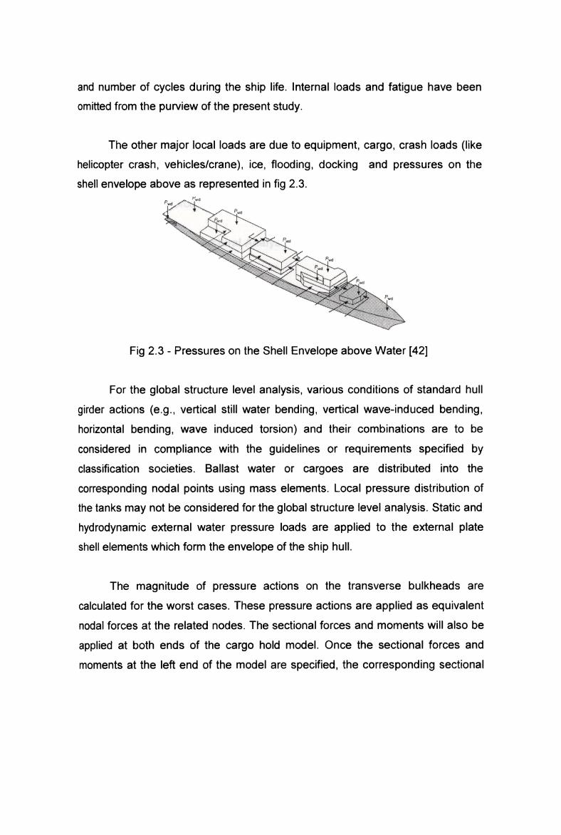
A structural component can fall into safe or failure state. The border line
(or surface) between the safe and failure states is named as limit state, and
expressed as g(Z) = R -S . The following conditions describe the possible states
of a structural component.
g(Z)<O represents a failure state where loads S exceeds the strength R.
g(Z)>O represents a safe state since strength R is larger than loads S.
g(Z)=O represents the limit state line (or surface).
Fig 2.7 shows the concept of limit state sketchily
G(Z)';R-S
‘Linn S!atc'g(Z)=0 ri .I V .4 7 .i Failure-‘Stale g(Z,')<0 ,l ~ . .Safe State g(Z)>O S “““"' “""“"" en
Fig 2.7 — Limit State Concept [4]

4U
For marine structures, the limit states are defined in accordance with the different
requirements, such as serviceability, ultimate strength, etc
First-Order Second Moment Method is used to assess the reliability of
structural components. FOSM method is also referred to as the Mean Value
First-Order Second-Moment method (MVFOSM). Based on a first-order Taylor
series approximation of the performance function linearised at the mean values
of the random variables, it uses only up to second-moment statistics (mean and
covariance) of the random variables.
The method only depends upon the mean and variance of individualrandom variables. Information about the distribution types of random variables is
not required, which leads to easy computation.
When the performance function is approximated to be linear, significant
errors may be introduced due to the higher order terms neglected. Since themethod does not use the distribution information about the variables even when it
is available, the accuracy of the results get reduced. The reliability index fails to
be constant under different but mechanically equivalent formations of the same
performance function, which leads to violation of invariance.
A performance function in the simple two-variable approach can be
defined as
Z= R-S. Assuming that R and S are statistically independent normally distributed
random variables, the performance function Z is also a normal random variable,
i.e.,
A/(,1, _p,.,,/6,} +aj) .......................................................... .. (2.1)
Where uR = mean value of strength R
us = mean value of the load effect S
or; = standard deviation of strength R
05 = standard deviation of the load

41
The event of failure is r<s, or z<0. The probability of failure can be evaluated as
pf= i>(Z<0)pf = <22)are "' ax
Of
(luR_/U3‘)pi=l~¢——-vi-—‘—— . . . . . . . . . . . . . . . . . . . . . . . . . . . . . . . . . . . . . . . . . . . . . . . . . . . . . . . . . ... (2.3)I [1/o'R‘ +082
where ¢> is cumulative distribution function (CDF) of the standard normal variable.
The probability of failure depends on the ratio of the mean value of Z to its
standard deviation. The ratio is known as Reliability lndex and is defined by
#7 1uR_)u\‘fl:——'—=lZ—~—‘— . . . . . . . . . . . . . . . . . . . . . . . . . . . . . . . . . . . . . . . . . . . . . . . . . . . . . . . . . ... (2.4)
O-Z \/UR2 +G.s'2
pf =1-¢(B) .......................................................... .. (2.5)The corresponding reliability is given as
R=1-pf .......................................................... .. (2.6)
Finite element nonlinear analysis for combined geometry and material
nonlinearities is carried out by keeping 10% variance in the values of modulus of
elasticity and 5% in the side shell thickness. The reliability factor is calculated
based on ultimate strength load factor predicted using this finite elementanalysis.
2.9 Summary
Ship structure is primarily a box structure composed of stiffened plates. It
possesses longitudinal symmetry but never remains prismatic. It is primarily

42
subjected to static loads like hydrostatic pressure, cargo loads etc.,. and wave
induced dynamic loads. The structural behaviour of ships basically is flexure of a
nonprismatic thin walled beam. The shells or plate of ship structure will be under
tensile or compressive stress resultants and the failure modes can broadly be
identified as yielding or buckling, which opens the necessity for nonlinear
structural analysis. The ultimate strength analysis of various structuralconfigurations of ships using finite element methods have widely been attempted
and extensive research has been published in this regard. A similar attempt has
been proposed in this study for slender warships. Uncertainties in ship structural
analysis are related to material and geometric features like yield strength,
fracture toughness, thickness, residual stress, and initial imperfections and above
all the wave induced loads. Reliability methods are now being introduced in ship
design to take care of such uncertainties. There are published work in this regard
and in the present study, First-Order Second Moment Method based reliability
analysis is conducted based on the ultimate strength prediction.