Embed Size (px)
Citation preview

The Control Panel sets certain global characteristics of the Warrior system. The Warrior Control Panel is started from its icon in the Warrior program group or via the Windows Program Menu. Warrior 8.0 now has several pages of information to set up system configurations. The pages of the Warrior Control Panel are General, Acquisition, Plot, Hot Keys, Licenses, and Depth/ Tension.
- The General page sets many of the typical settings from the Warrior 7.0 control panel.
.
FIG: 3.0.1 Warrior Control Panel General page

3.1.1 Show Depth as The option buttons in the upper left set the default depth units for the system. The choices are Feet or Meters.
FIG: 3.1.1 Depth units 3.1.2 Show Data Units as
Data Units as allows the user to select one of three choices for the data units to be used.
FIG: 3.1.2 Depth units By clicking on the [Edit] button, the user can select the actual units to be used for each of the 3 choices. Note that English units do not necessarily mean that they have to be English units. This is merely a means to identify one of the three units choices and to use those units as the defaults during program operation.
FIG: 3.1.3 Unit maps for the 3 data choices

3.1.3 Use Language The drop down list allows the User to set the language of the user interface for the system. Several choices are expected to be available shortly.
FIG: 3.1.4 Languages 3.1.4 Warrior data directory This item indicates the current Windows directory for the default storage of Warrior database files. To change the folder, click on the [Browse] button and navigate to an existing folder or click on [Make New Folder] to create a new folder for data storage.
It is highly recommended to use \ProgramData\Warrior\
FIG: 3.1.5 Default Warrior data storage folder 3.1.5 Setting up Real Time Backup If something should happen to corrupt the original database through a faulty merge or recalculation, copies of the original passes would still be available. While in acquisition, recording data, at the end of a log pass, the data from that pass is copied into the backup database. The User is given three options. The first is to make no backups. The next option is to give the User a prompt asking if they want to make a copy of that pass. The final option will automatically make the backup without the prompt. The User also has the option of using the [Browse] button to select the folder to be used for storing backup databases.
It is highly recommended that real time backup files be created.
Fig. 3.1.6 Setting real time backup

Fig. 3.1.7 Setting real time backup directory 3.1.6 Current Warrior Software Version The currently installed Warrior Software version is shown on the bottom of the General page in the Warrior Control Panel.
Fig. 3.1.8 Current Warrior Software version

-The acquistion page of the Warrior control Panel sets up many of the general settings that are used while acquiring data.
Fig. 3.2.1 Warrior Control Panel Acquistion page 3.2.1 Acquisition system settings The Panel Type is read from the Warrior Software key that is stored in the panel and reflects the hardware that is currently installed in the panel. This should be grayed out so that the User cannot inadvertently change the panel type. If different revisions of boards are installed in the panel, contact Scientific Data Systems for directions on how to change the panel type to reflect the board changes.
Fig. 3.2.2 Panel type setting 3.2.2 Refresh Monitor settings The User has control over how often the Waveform windows and numeric windows such as monitoring outputs or sensors are refreshed. The default settings for refreshing windows is 1000 msec, or once per second. Be aware that while putting a lower value in for these settings will refresh the windows faster, that it will also put a lot of overhead computing power on the computer to do this and may slow down the response of the computer.
Fig. 3.2.3 Monitor Refresh settings.

3.2.3 Cable Selection Settings The User has the ability to specify different cables to be used. This way each cable can have different settings for use as in a split drum unit or moving the computer among different units.
Fig. 3.2.4 Cable Selection settings. New cables can be added to the drop down list of cable selections by clicking Add new type. When the [OK] button is clicked, the new description will be added to the cable selection drop down list.
Fig. 3.2.5 Entering new cable description.. Existing cables may be removed from the drop down list by first selecting the cable to be removed and then clicking the [Remove] button. A confirmation window will come up to confirm removal of the selected cable. Each cable in the drop down list can have its own line resistance setting. To assign a line resistance to a particular line, select the line, enter the line resistance in ohms, and then click the [Set] button to assign that resistance to the cable selected. Line resistance is a User defined value. Most services will have HVOLTA as an output. HVOLTA is computed by taking the TCURR output (tool current) and multiplying by the Line resistance value and then subtracting this value from the TVOLT output (tool voltage) to give an apparent head voltage. Note that HVOLTA will not be accurate unless the tool voltage and tool current are properly calibrated and the line resistance is the correct value for the line being used. It is a given fact the the phisical characteristics of a cable can effect the shape of signals on the cable. By adding the SignalType control keyword to a service, different cables can each have different line filter settings for that service.The User would be allowed to select a cable type that would then set cetain filter setting for specific signal types. This is discussed further in Section 16 3.2.3 Default Font for Gauges The dropdown list allows the User to select the Windows font that he would like to use for gauges in Acquisition.
Fig. 3.2.6 Setting Font for Gauges

3.2.4 Other Acquisition Options There are several other options that may be set from the acquisition that would affect how the Warrior software would work. The first option is to show the tool string editor automatically when a service is selected. The tools to be included in the tool string are shown when the service is loaded into the software in the tool editor window. The tools chosen will affect what outputs are available, what the sensor offsets for each output are, what filtering is used on the outputs, and what the calibrations are used for an output.
It is highly recommended that this option be checked and the tool string editor used every time the service is started so that the User looks at the tools in the string. If the Warn about losing depth if moving box is checked, the software will issue a warning if the depth is changing while a service would be loading. There is a short period of time while the software is loading that depth pulses to the panel would be missed. For the typical User in the field, this box should be checked. The User may select the font that is used in the Acquisition window by clicking the [Edit font] button. This brings up a dialog window that allow the font, font style, and size to be selected. The selected font will then be used in the Acquistion window. If a service has been made available for perforating in the Service Editor, then checking the if perforating service box will have the service pop up a message with the zero point of the tool string when the service loads. By checking the next box, the Acquisition window will always be on top even if other windows are moved over it. If the Depth window is selected to always be on top also, then it could cover the acquisition window if the depth window is moved over the acquistion window. The update with max range of data check box changes the start and stop depth of a log pass from the encoder depths when the pass was started and stopped to the maximum output depths at the start and at the end of a log pass. The default log depth scale is the number of feet of well log per foot of paper. The standard in the US is 240 ft of log per foot of paper or 100 foot per 5 inches. The default log time scale is the number of seconds of log per inch of paper. The default setting of 10 will give 10 seconds of log for 1 inch of paper or 120 seconds of log per fool of paper. The log time rate is the default for the number of data sample to be recorded to the database per second. The default rate of 10 works well in most instances.

Fig. 3.2.7 Other option settings for Acquistion
The plot page of the Warrior Control Panel is used to setup plotters and also allow the User to set up many of the parameters and functions used by Warrior software in the plotting of logs. 3.3.1 Plotting Gridline Setup
Fig. 3.3.1 Plotting Setup The plotting of horizontal depth gridlines can be set up by adjusting the scale factors for the gridlines. If the vertical scale resolution on the plot is less than the maximum compression ratio, and the scale resolution is greater than the minimum compression ratio, than the gridline will be plotted. Separate gridline setups can be kept for English depth, Metric depth, and a time log. In the setup shown in Fig. 3.3.2, the 50 foot depth line will be on the plot unless the scale is less than 12000
ave two foot depth
lines since they have a minimum range of 25, but it will have 1 foot depth lines since the 20 scale is less than the 1.0 foot maximum of 25.

FIG: 3.3.2 Horizontal Gridline Setup 3.3.2 Plotting Printer Setup There are two different plotting modes that Warrior software can use to plot data. In the Direct Print mode, printer drivers contained in the Warrior Software allow real time printing while acquiring data and use only the Windows spooling function. In Windows mode, the Warrior software prints the data through the Windows installed printer drivers. Windows mode should not be used for real time printing. For good quality color prints, or to print to a printer that is not in the list of supported Direct Print mode printers, select the option Enable printing through Windows printer". If you have that option checked, then when you print from Warrior, you will see either (Direct) or (Windows) label for each printer in the list of printers to print to. Direct to Printer Printers supported for Direct printing by Warrior, also have Windows drivers, so when a Direct Printer is installed; the Windows driver must be installed as well for printer spooling. When selecting a printer name, as would be done during a printer selection in Windows programs, Warrior can use the port properties you set up for that printer through the standard Windows printer setup, so the port name doesn't have to be specified in two different places. When a Windows name is specified, then the Port Name doesn't need to be changed in Warrior, as it will use the same port that is set up through your standard Windows printer setup. When using Direct printing, settings, such as media type, plot speed, etc., are all controlled by Warrior software directly, not by the Windows printer driver. Printers supported by Warrior Software for monochrome printing Direct: Printrex 820 and 820 DL and the 840 DL/G or 843 DL/G and 920 ( www.printrex.com ) ISys V8.5 or V8.5e ( www.isys-group.com ) Printers supported by Warrior Software for color printing Direct: Epson Stylus Color 900 Epson Stylus Color 1520 Epson Stylus Color 3000 Epson Stylus Color C60, C80, C82, C84 HP DesignJet 750C, 1050C HP LaserJet 5L In addition PDF and image (TIFF) file can also be made directly.

Fig. 3.3.3 Warrior Control panel Printer Setup Printing through Windows Printing While logging, it is possible to print to a Windows printer. However, printing hardcopy of your pass that you are currently logging is not possible do to Windows printing full pages at a time. SDS cannot guarantee that all printers will work properly for making prints from Warrior, therefore a list of tested printers that are able to make continuous prints, is available. The Windows printing options are settings that may change from one printer to the next. However, most of the settings are set by SDS, so they should not be changed. Some printers place a large gap at the start of a print, so a print gap is added during start of print, so the first fan fold can be skipped and a distance can be added to get the <fold here> to come out in the right place. When using Windows printing, settings, such as media type, plot speed, etc., are all controlled by the Windows printer driver.
3.3.3 Plotting Installing a Direct Warrior Printer From the Warrior Control Panel, click the Plot tab. From the plot sheet, click on the [Printer Setup] button. From the Installed Printers window, select the [Install] button at the bottom of the page for a list of printers supported by Warrior for direct printing while logging.

Fig. 3.3.4 Warrior Installed Printers Setup
FIG: 3.3.5 Install Printer Open the Drop- down list to view the list of printers. Note that there is a scroll bar to the side of the list to scroll up and down to view all of the selectable printers.

FIG: 3.3.6 Install Printer In this example we will select Printrex for the Printrex 840 DL/G.
FIG: 3.3.7 Install Printer Click the [Install] button to select the printer shown for installation.
FIG: 3.3.8 Printrex 820/840 Plotter Configuration The Plotter Configuration window for the plotter selected will now open. In this example, the Media can be paper or film. Depending upon the media selected, the plotter will run at either the paper speed or the film speed. The sensitivity setting controls the heat selection for the thermal paper or film that is installed. A low sensitivity will increase the heat setting. For fan fold printing, set the printer page height to twice the size of one fan fold page.

non-zero value will cause the printer to advance the paper that distance, so the first fan fold page may be blank in order to position the print head to the proper place. Select [Save] to save the plotter configuration. One physical plotter in a system can be installed under different names and each installation can then have different configuration settings and/or printer calibrations. To install multiple configurations for the same physical plotter, start the installation by clicking the [Install] on the lower portion of the screen. Find and select the plotter in the drop- down list. If that plotter name already exists in the list of installed plotters, you will be given the option of entering a new name. Click the [Rename] button to continue to the configuration window for that plotter name.
Fig. 3.3.9 Entering Second plotter name for existing plotter Once the plotter has been selected and installed, the plotter used for windows spooling needs to be selected. This plotter must already have been installed in windows as discussed in section 2.1.
FIG: 3.3.10 Installed Printers Select the Drop-down list for the Name of this printer as seen by Windows printers and select the Windows installed printer. If no plotter is selected you will get the plotter may be off-line error message when you try to print from Warrior.

FIG: 3.3.11 Installed Printers Select [Save Changes] to save the installed plotter and its configuration settings. 3.3.4 Printing to PDF Warrior supports direct printing to PDF files through its own driver. Before creating a PDF output, determine what the customer intends to do with the file and configure the PDF configuration options accordingly. If it is intended only to view the PDF on the screen, then the driver should be set to Continuous Viewable Image and Color. If the customer intends to print the PDF, then it should be set to Continuous Printable Image and Color or Monochrome, depending on the printer being used. In addition, it may be important to set the page size to match the page size of the customer's printer; otherwise gaps between pages can appear. Furthermore, there is a trade off between file size and quality. The higher the dpi setting, the better the quality normally, but the file size is larger. Some experimentation may be required with the customer to produce optimal results. This is also true for the selected compression mode. For most situations, FLATE compression works well. 3.3.5 Printing to TIFF Warrior also supports direct printing to TIFF files through its own driver. Again, determine what the file is intended for and configure the driver accordingly. Note that the driver supports TIFF single continuous pages of longer than 90 inches. However, many TIFF applications (including Warrior fax) do not support this, so before increasing the maximum page length make sure that the customer can read such files. 3.3.6 Windows Printing Check Enable printing through Windows printer. When this box is checked, either a (Direct) or (Windows) label for each available printer is shown when printing from Warrior. COLOR PRINTING NOTICE: You will always get better color prints printing through a Windows color printer. None of the direct color printers were designed for printing continuous log prints. Unless you require color printing while logging, we recommend you use one of the Windows printers and not use Direct printing to a color printer. There are several settings that need to be set to achieve a quality print using Windows printers. By clicking on [Printing Help] you can read further about settings.

Fig. 3.3.12 Printing Help If you click on the Supported Windows Printers, a list of printers will drop down. If you click on one of the listed printers, settings for Windows printing from Warrior will be shown. In addition, suggested settings for the Windows printer properties will be listed.
Fig. 3.3.13 Supported Windows Printers Source Resolution: If it takes a long time to print to your Windows printer, try setting this to a lower value. The default is 1. A lower value may degrade the print quality, so test with your printer to find the optimal setting. You may be able to use a higher Windows printer resolution ( 600 or 720 dpi ) and use a Source Resolution of 1/2 or 1/3 and still get a quality print.

3.3.7 Finding Printer We recommend connect the Printer/Plotter in the same USB port but if you do not know which port to use, you can find the USB port where the printer is connected. This will work for printers that print only through Windows or for printers that use the Windows spooler for direct printing through Warrior.
FIG: 3.3.14 Installed Printers Select on the Drop-down the Printer that you wish to find what USB port it is attached to. In this case Printrex 840DL/G.
FIG: 3.3.15 Installed Printers Click on the [Find this Printer on USB port] button. The find printer dialog box will come up. At this time it is important to disconnect any plotter that is not the plotter that you are trying to locate. A sample test page will be sent to the plotter and if the plotter is not the correct plotter being tested it may generate large amounts of wasted paper.
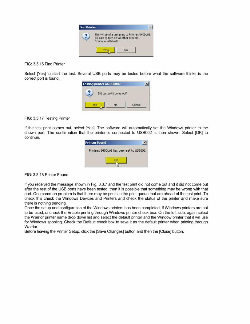
FIG: 3.3.16 Find Printer Select [Yes] to start the test. Several USB ports may be tested before what the software thinks is the correct port is found.
FIG: 3.3.17 Testing Printer If the test print comes out, select [Yes]. The software will automatically set the Windows printer to the shown port. The confirmation that the printer is connected to USB002 is then shown. Select [OK] to continue.
FIG: 3.3.18 Printer Found If you received the message shown in Fig. 3.3.7 and the test print did not come out and it did not come out after the rest of the USB ports have been tested, then it is possible that something may be wrong with that port. One common problem is that there may be prints in the print queue that are ahead of the test print. To check this check the Windows Devices and Printers and check the status of the printer and make sure there is nothing pending. Once the setup and configuration of the Windows printers has been completed, If Windows printers are not to be used, uncheck the Enable printing through Windows printer check box. On the left side, again select the Warrior printer name drop down list and select the default printer and the Window printer that it will use for Windows spooling. Check the Default check box to save it as the default printer when printing through Warrior. Before leaving the Printer Setup, click the [Save Changes] button and then the [Close] button.

FIG: 3.3.19 Installed Printers
FIG: 3.3.20 Installed Printers
FIG: 3.3.21 Installed Printers

3.3.8 Plotting Options
FIG: 3.3.22 Other plotting options If the Monitor USB port while printing is checked, then if the software does not receive a response from the plotter within the time that is specified, a prompt to try other USB ports will be shown. It is highly recommended that this box be checked. Some plotters that are connected to the computer via parallel port may require that the status of the plotter not be checked. This is only for specific plotters such as an older Gulton that are connected to a parallel port and not a USB port. The default heading that is used in the Heading Editor may be selected by click the [Browse] button. All of the headings in the C:\ProgramData\Warrior\Format\ folder will be shown. The User can select any heading and install it as the default by clicking the [OK] button. Similarly the default log banner may be selected by its [Browse] button. 3.3.9 Plotting Service Company The text that is entered in this field will appear in LAS files as the Service Company Name.
Fig. 3.3.23
and place short cuts for the Warrior\Config\ folder and the current Warrior Data folder in the Favorites section of Windows Explorer.

FIG: 3.4. Hot Key setup
- The first functionality of this section of the Warrior Control Panel is to show the key number of the Warrior Software key that is attached to the computer, either directly or through the USB hub in the interface panel. This is shown in the Key serial #: window as #Uxxxx, where the xxxx is the key. If no key is currently seen by the software, you will see
FIG: 3.5.1 Warrior Key License Codes

Unlike previous versions of Warrior Software that required a single license code, the Warrior 8 software has a different code for each of the software module types. Inthe license code for the key serial # that is shown. If no license has been entered the code will be blank. The User has the option of hand entering the 16 digit hexadecimal code for a particular license and saving it, much like previous version of Warrior. Due to the number of codes that must be entered correctly for all of the software permissions, the User can now import multiple codes for multiple software keys at the same time by clicking on the [Import from File] button and selecting the proper license file supplied by Scientific Data Systems.
FIG: 3.6.1 Warrior Control Panel - Depth / Tension The input section of the Depth / Tension page of the Warrior Control panel allows the User to specify the signal input used for both Depth and Tension. At the present time, depth can come from the Interface panel encoder input or from the ASEP Smart Monitor. Tension can come from the interface tension input, line load module input (AUX1 BNC ), or the ASEP Smart Monitor.
FIG: 3.6.2 Depth and Tension input selection

There are several other options for displaying the depth window. The depth may be displayed with 1 decimal point (0.0, normally used when depth is in feet), or with 2 decimal points (0.00, used when depth is in meters). The normal refresh rate of the depth window is 500 milliseconds. This can be changed by the User to be updated more or less often. be on top no matter what its position is. The software normally shows speed as a negative value when logging up (depth decreasing). By checking
FIG: 3.6.3 Depth display options


![0HDVXUHPHQW RI WKH 3KDVH 'LIIHUHQFH EHWZHHQ … · 2019. 7. 11. · 7kh 6hwxs (= 5rkgh 6fkzdu] 0hdvxuhphqw ri wkh 3kdvh 'liihuhqfh ehwzhhq vhyhudo 6ljqdov 7kh 6hwxs %orfn gldjudp](https://img.pdfslide.us/doc/110x75/60e3e6de07df745ae6427f73/0hdvxuhphqw-ri-wkh-3kdvh-liihuhqfh-ehwzhhq-2019-7-11-7kh-6hwxs-5rkgh-6fkzdu.jpg)

![SSP 2017 - entry form v2 - somersetsongprize.org.uk · 7kh 6rphuvhw 6rqj 3ul]h lv surxg wr eh dvvrfldwhg zlwk wkh 7dxqwrq )hvwlydo ri wkh $uwv 5hjlvwhuhg &kdulw\ 1r 7kh )hvwlydo lv](https://img.pdfslide.us/doc/110x75/5c89002f09d3f2224c8c7494/ssp-2017-entry-form-v2-7kh-6rphuvhw-6rqj-3ulh-lv-surxg-wr-eh-dvvrfldwhg.jpg)


![7KH )RXUWK 5HSRUW RI WKH &RQJUHVVLRQDO ... - …...7kh hiihfwlyhqhvv ri ordqv ordq jxdudqwhhv dqg lqyhvwphqwv pdgh xqghu 6xewlwoh $ lq plqlpl]lqj orqj whup frvwv wr wkh wd[sd\huv dqg](https://img.pdfslide.us/doc/110x75/5ffe8d454179565e80403ee1/7kh-rxuwk-5hsruw-ri-wkh-rqjuhvvlrqdo-7kh-hiihfwlyhqhvv-ri-ordqv.jpg)