Embed Size (px)
Citation preview

Please observe the following safety precautions in order touse safely and correctly the refrigerator and to preventaccident and danger during repair.
1. Be care of an electric shock. Disconnect power cordfrom wall outlet and wait for more than three minutesbefore replacing PWB parts. Shut off the powerwhenever replacing and repairing electric components.
2. When connecting power cord, please wait for more thanfive minutes after power cord was disconnected from thewall outlet.
3. Please check if the power plug is pressed down by therefrigerator against the wall. If the power plug wasdamaged, it may cause fire or electric shock.
4. If the wall outlet is over loaded, it may cause fire. Pleaseuse its own individual electrical outlet for the refrigerator.
5. Please make sure the outlet is properly earthed,particularly in wet or damp area.
6. Use standard electrical components when replacingthem.
7. Make sure the hook is correctly engaged. Remove dust and foreign materials from the housingand connecting parts.
8. Do not fray, damage, machine, heavily bend, pull out,or twist the power cord.
9. Please check the evidence of moisture intrusion in theelectrical components. Replace the parts or mask itwith insulation tapes if moisture intrusion wasconfirmed.
10. Do not touch the icemaker with hands or tools toconfirm the operation of geared motor.
11. Do not let the customers repair, disassemble, andreconstruct the refrigerator for themselves. It maycause accident, electric shock, or fire.
12. Do not store flammable materials such as ether,benzene, alcohol, chemicals, gas, or medicine in therefrigerator.
13. Do not put flower vase, cup, cosmetics, chemicals,etc., or container with full of water on the top of therefrigerator.
14. Do not put glass bottles with full of water into thefreezer. The contents shall freeze and break the glassbottles.
15. When you scrap the refrigerator, please disconnect thedoor gasket first and scrap it where children are notaccessible.
WARNINGS AND PRECAUTIONS FOR SAFETY
- 3 -

SPECIFICATIONS
- 6 -
ITEMS SPECIFICATIONS
DIMENSIONS (mm) 890(W)X840(D)X1750(H)
NET WEIGHT (kg) 125
COOLING SYSTEM Fan Cooling
TEMPERATURE CONTROL Micom Control
DEFROSTING SYSTEM Full Automatic
Heater Defrost
INSULATION Cyclo-Pentane
COMPRESSOR P.T.C. Starting Type
EVAPORATOR Fin Tube Type
CONDENSER Wire Condenser
REFRIGERANT R134a (185g)
LUBRICATING OIL FREOL @15G (320 cc)
DRIER 1Ø0.83
ITEMS SPECIFICATIONS
CAPILLARY TUBE MOLECULAR SIEVE XH-7
FIRST DEFROST 4 - 5 Hours
DEFROST CYCLE 13 - 15 Hours
DEFROSTING DEVICE Heater, Sheath
Heater, L-Cord
ANTI SWEAT HEATER Dispenser Duct Door Heater
Dispenser Heater
ANTI-FREEZING HEATER Water Tank Heater
Damper Heater
FREEZER LAMP 40W (1 EA)
REFRIGERATOR LAMP 40W (1 EA)
DISPENSER LAMP 15W (1 EA)
1750
1720
1750
685
948
89074
579
684
012
18.5
<Front View> <Plane View>
3. Ref No. : GR-L247

SPECIFICATIONS
- 7 -
ITEMS SPECIFICATIONS
DIMENSIONS (mm) 890(W)X755(D)X1750(H)
NET WEIGHT (kg) 120
COOLING SYSTEM Fan Cooling
TEMPERATURE CONTROL Micom Control
DEFROSTING SYSTEM Full Automatic
Heater Defrost
INSULATION Cyclo-Pentane
COMPRESSOR P.T.C. Starting Type
EVAPORATOR Fin Tube Type
CONDENSER Wire Condenser
REFRIGERANT R134a (185g)
LUBRICATING OIL FREOL @15G (320 cc)
DRIER 1Ø0.83
ITEMS SPECIFICATIONS
CAPILLARY TUBE MOLECULAR SIEVE XH-7
FIRST DEFROST 4 - 5 Hours
DEFROST CYCLE 13 - 15 Hours
DEFROSTING DEVICE Heater, Sheath
Heater, L-Cord
ANTI SWEAT HEATER Dispenser Duct Door Heater
Dispenser Heater
ANTI-FREEZING HEATER Water Tank Heater
Damper Heater
FREEZER LAMP 40W (1 EA)
REFRIGERATOR LAMP 40W (1 EA)
DISPENSER LAMP 15W (1 EA)
1750
1720
1750
600
948
89066
071
175
511
33.5
<Front View> <Plane View>
4. Ref No. : GR-L207
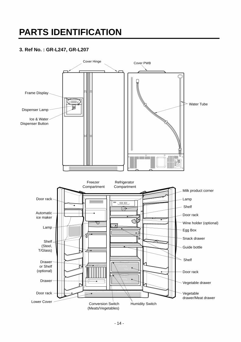
PARTS IDENTIFICATION
- 14 -
Cover PWB
Water Tube
Humidity Switch
Lamp
Shelf
Egg Box
Snack drawer
Vegetable drawer
Vegetabledrawer/Meat drawer
Door rack
Guide bottle
Shelf
Door rack
Wine holder (optional)Lamp
Shelf(Steel,
T/Glass)
Draweror Shelf
(optional)
Lower Cover
Milk product corner
Door rack
Drawer
Freezer Compartment
Refrigerator Compartment
Automaticice maker
Door rack
Conversion Switch(Meats/Vegetables)
Cover Hinge
Frame Display
Dispenser Lamp
Ice & WaterDispenser Button
3. Ref No. : GR-L247, GR-L207

4. Ref No. : GR-L247, GR-L207
PARTS IDENTIFICATION
- 15 -
Conversion Switch(Meats/Vegetables)
Cover PWB
Water Tube
Humidity Switch
Lamp
Shelf
Egg Box
Snack drawer
Vegetable drawer
Vegetabledrawer/Meat drawer
Door rack
Guide bottle
Shelf
Door rack
Wine holder (optional)Lamp
Shelf(Steel,
T/Glass)
Draweror Shelf
(optional)
Lower Cover
Milk product corner
Door rack
Drawer
Freezer Compartment
Refrigerator Compartment
Automaticice maker
Door rack
Cover Hinge
Frame Display
Dispenser Lamp
Ice & WaterDispenser Button

1. Monitor Panel
1-1. GR-P247, GR-P207, GR-L247, GR-L207 1-2. GR-C247, GR-C207, GR-B247, GR-B207
2. Description of Function
2-1. Funnction of Temperature Selection
* The temperature can vary ±3 °C depending on the load condition. *( ) : 127V/60Hz, 110~115V/60Hz, 115V/60Hz Rating ONLY.
*< > : TAIBEI
1. When power is initially applied or reapplied after power cut, “Medium” is automatically selected.
2. When the temperature selection switch in the freezer and refrigerator compartments is pressed, the light is on in thefollowing sequence:"Medium" "Medium Max" "Max" "Min" "Medium Min" "Medium"
3. The temperature setting condition of freezer and refrigerator compartments shall not be indicate in the standard model(GR-P247, GR-P207, GR-L247, GR-L207, GR-C247, GR-C207, GR-B247, GR-B207) when refrigerator or home bardoor is closed.
MICOM FUNCTION
- 25 -
FRZTemp
REFTemp SELECT
Max
Min
Function Monitor
Freezer compartmenttemperature control Button
Refrigerator compartmenttemperature control Button
Dispenser selection button
1 2 3 4 55Max MaxMin4 3 2 1
FRZTemp
REFTemp
Division Power Initially On 1st Press 2nd Press 3th Press 4th Press
Change of Indication Lamp
Temperature Control
Medium Medium Max Max Min Medium Min
Freezer -19 °C -22 °C -23 °C-15 °C -17 °CControl (-18 °C) (-20.5 °C) (-22 °C)
<-19 °C> <-20.5 °C> <-22 °C> <-16.5 °C> <-18 °C>
Refrigeration 3 °C 1.5 °C 0°C
6 °C4.5 °CControl (7 °C)
<2 °C> <1 °C> <0 °C> <4.5 °C> <3 °C>
FRZTemp
REFTemp
FRZTemp
REFTemp
FRZTemp
REFTemp
FRZTemp
REFTemp
FRZTemp
REFTemp
Max
Min
Max
Min
Max
Min
Max
Min
Max
Min
2-2. Automatic ice maker• The automatic ice maker can automatically make 8 pieces of ice cube at a time, 80 pieces a day. But these quantities may
be varied according to various conditions including how many times the refrigerator door opens and closes.
• Ice making stops when the ice storage bin is full.
• If you don’t want to use automatic ice-maker, change the ice-maker switch to ON-OFF.If you want to use automatic ice-maker again, change the switch to OFF-ON.
NOTE : It is normal that a noise is produced when ice made is dropped into the ice storage bin.
2-3. When ice maker does not operate smoothlyIce is lumped together
• When ice is lumped together, take the ice lumps out of the ice storage bin, break them into small pieces, and then placethem into the ice storage bin again.
• When the ice maker produces too small or lumped together ice, the amount of water supplied to the ice maker need toadjusted. Contact the service center.
If ice is not used frequently, it may lump together.
Power failure
• Ice may drop into the freezer compartment. Take the ice storage bin out and discard all the ice then dry it and place itback. After the machine is powered again, crushed ice will be automatically selected.
The unit is newly installed
• It takes about 12 hours for a newly installed refrigerator to make ice in the freezer compartment.
MICOM FUNCTION
- 26 -

2-4. Control of variable type of freezing room fan1. To increase cooling speed and load response speed, MICOM variably controls freezing room fan motor at the high speed
of RPM and standard RPM.
2. MICOM only operates in the input of initial power or special freezing operation or load response operation for the highspeed of RPM and operates in the standard RPM in other general operation.
3. If opening doors of freezing / cold storage room or home bar while fan motor in the freezing room operates, the freezingroom fan motor normally operates (If being operated in the high speed of RPM, it converts operation to the standardRPM). However, if opening doors of freezing room or home bar, the freezing room fan motor stops.
4. As for monitoring of BLDC fan motor error in the freezing room, MICOM immediately stops the fan motor by determiningthat the BLDC fan motor is locked or poor if there would be position signal for more than 65 seconds at the BLDC motor.Then it displays failure (refer to failure diagnosis function table) at the display part of refrigerator, performs re-operation inthe cycle of 30 minutes. If normal operation is performed, poor status is released and refrigerator returns to the initialstatus (reset).
2-5. Control of M/C room fan motor1. The M/C room fan motor performs ON/OFF control by linking with the COMP.
2. It controls at the single RPM without varying RPM.
3. Failure sensing method is same as in fan motor of freezing fan motor (refer to failure diagnosis function table for failuredisplay).
2-6. Door opening alarm1. Buzzer generates alarm sound if doors are not closed even when more than a minute consecutively has passed with
doors of freezing / cold storage room or home bar opened.
2. Buzzer rings three times in the interval of 0.5 second after the first one-minute has passed after doors are opened andthen repeats three times of On/Off alarm in the cycle of every 30 seconds.
3. If all the doors of freezing / cold storage room or home bar are closed during door open alarm, alarm is immediatelyreleased.
2-7. Ringing of button selection buzzer1. If pressing the front display button, “Ding ~ “ sound rings.
2-8. Ringing of compulsory operation, compulsory frost removal buzzer1. If pressing the test button in the main PCB, “Phi ~ “ sound rings.
2. In selecting compulsory operation, alarm sound is repeated and completed in the cycle of On for 0.2 second and Off for1.8 second three times.
3. In selecting compulsory frost removal, alarm sound is repeated and completed in the cycle of On for 0.2 second , Off for0.2 second, On for 0.2 second and Off for 1.4 second three times.
MICOM FUNCTION
- 27 -
Doors of freezing / cold storage room
or home bar
BUZZER
Closing Opening
Withina minute
A minute 30seconds
30seconds
30seconds
OpeningClosing Closing
3 Times 3 Times 3 Times 3 Times

2-9. Frost removal function1. Frost removal is performed whenever total operation time of compressor becomes 7 ~ 7.5 hour.
2. In providing initial power (or returning power failure), frost removal starts whenever total operation time of compressorbecomes 4 ~ 4.5 hour.
3. Frost removal is completed if temperature of a frost removal sensor becomes more than 5°C after starting frost removal.Poor frost removal is not displaced if it does not arrive at 5°C even if two hours have passed after starting frost removal.
4. No removal is done if frost removal sensor becomes poor (snapping or short-circuit).
2-10. Sequential operation of built-in productBuilt-in products such as compressor, frost removal heater, freezing room fan, Cooling Fan and step motor damper aresequentially operated as follows for preventing noise and part damage occurred due to simultaneous operation of a lot ofparts in applying initial power and completing test.
MICOM FUNCTION
- 28 -
Function Load Operation Sequence Remark
Inapplying
Initialpower
TE
ST
MO
DE
When temperatureof a frost removalsensor becomesmore than 25°C (In purchase,movement)
If error occursduring operation,initial operation isnot done.
If pressing switchonce more in thetest mode 2 ortemperature of afrost removalsensor is morethan 5°C, itimmediatelyreturns to the testmode for initialoperation (COMP operatesafter 7 minutes).
Whentemperature of afrost removalsensor becomesless than 25°C (In power failure,service)
Test mode 1 (Compulsoryfunction)
Test mode 2 (Compulsory frostremoval)
POWER
ON
COMP
ON
COMP
ON
WATERTANK
HEATERON
F-FAN&
C-FANON
F-FAN&
C-FANON
F-FAN&
C-FANON
F-FAN&
C-FANOFF
WATERTANK
HEATEROFF
STEPMOTOR
DAMPERON
STEPMOTOR
DAMPEROPEN
STEPMOTOR
DAMPERCLOSE
HOMEBAR
HEATERON
POWER
ON
FROSTREMOVALHEATER
ON
HOMEBAR
HEATEROFF
HOMEBAR
HEATERON
TESTS/W
(PressOnce)
COMP
ON
TESTS/W
(Press2 times)
COMP
OFF
0.5sec.
0.3sec.
0.3sec.
0.3sec.
0.5sec.
8sec.
0.3sec.
5sec.
FROSTREMOVALHEATER
OFF
FROSTREMOVALHEATER
ON
5sec.
0.3sec.
WATERSUPPLY
&DISPENSEHEATER
ON
5sec.
0.3sec.
0.3sec.
0.3sec.
0.3sec.
0.3sec.
0.3sec.
0.3sec.
0.3sec.
OTHERLOADOFF
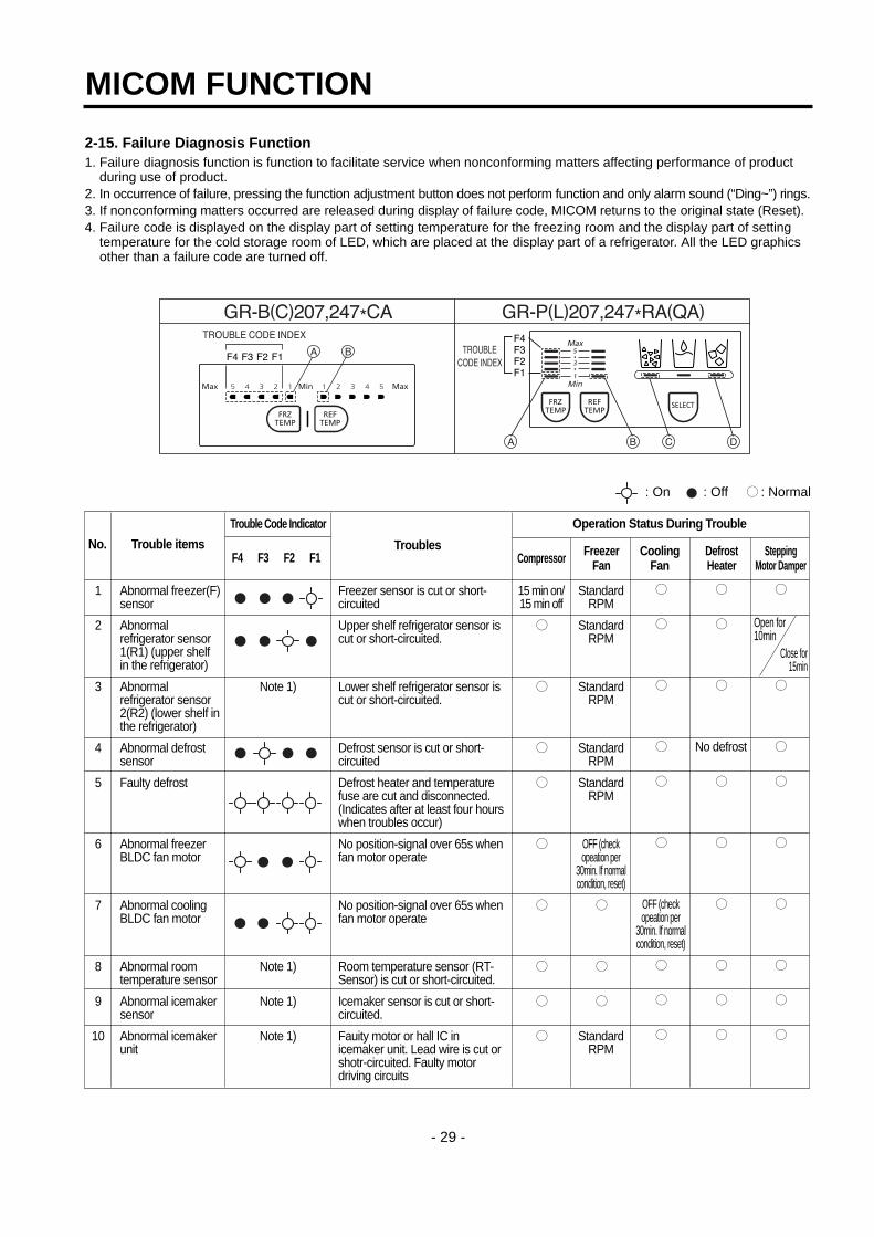
2-15. Failure Diagnosis Function1. Failure diagnosis function is function to facilitate service when nonconforming matters affecting performance of product
during use of product.2. In occurrence of failure, pressing the function adjustment button does not perform function and only alarm sound (“Ding~”) rings.3. If nonconforming matters occurred are released during display of failure code, MICOM returns to the original state (Reset).4. Failure code is displayed on the display part of setting temperature for the freezing room and the display part of setting
temperature for the cold storage room of LED, which are placed at the display part of a refrigerator. All the LED graphicsother than a failure code are turned off.
MICOM FUNCTION
- 29 -
: On : Off : Normal
1
2
3
4
5
6
7
8
9
10
Note 1)
Note 1)
Note 1)
Note 1)
Trouble Code Indicator
F4 F3 F2 F1No. Trouble items Troubles Freezer
FanCompressor SteppingMotor Damper
DefrostHeater
CoolingFan
Operation Status During Trouble
Abnormal freezer(F)sensor
Abnormalrefrigerator sensor1(R1) (upper shelfin the refrigerator)
Abnormalrefrigerator sensor2(R2) (lower shelf inthe refrigerator)
Abnormal defrostsensor
Faulty defrost
Abnormal freezerBLDC fan motor
Abnormal coolingBLDC fan motor
Abnormal roomtemperature sensor
Abnormal icemakersensor
Abnormal icemakerunit
Freezer sensor is cut or short-circuited
Upper shelf refrigerator sensor iscut or short-circuited.
Lower shelf refrigerator sensor iscut or short-circuited.
Defrost sensor is cut or short-circuited
Defrost heater and temperaturefuse are cut and disconnected.(Indicates after at least four hourswhen troubles occur)
No position-signal over 65s whenfan motor operate
No position-signal over 65s whenfan motor operate
Room temperature sensor (RT-Sensor) is cut or short-circuited.
Icemaker sensor is cut or short-circuited.
Fauity motor or hall IC inicemaker unit. Lead wire is cut orshotr-circuited. Faulty motordriving circuits
StandardRPM
StandardRPM
StandardRPM
StandardRPM
StandardRPM
OFF (checkopeation per
30min. If normalcondition, reset)
StandardRPM
OFF (checkopeation per
30min. If normalcondition, reset)
15 min on/15 min off
No defrost
Open for10min
Close for15min
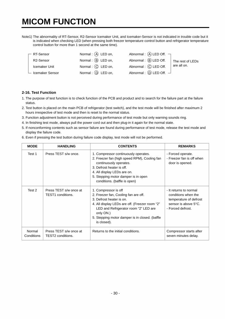
Note1) The abnormality of RT-Sensor, R2-Sensor Icemaker Unit, and Icemaker-Sensor is not indicated in trouble code but itis indicated when checking LED (when pressing both freezer temperature control button and refrigerator temperaturecontrol button for more than 1 second at the same time).
RT-Sensor Normal : A LED on, Abnormal : A LED Off.
R2-Sensor Normal : B LED on, Abnormal : B LED Off.
Icemaker Unit Normal : C LED on, Abnormal : C LED Off.
Icemaker Sensor Normal : D LED on, Abnormal : D LED Off.
2-16. Test Function1. The purpose of test function is to check function of the PCB and product and to search for the failure part at the failure
status.
2. Test button is placed on the main PCB of refrigerator (test switch), and the test mode will be finished after maximum 2hours irrespective of test mode and then is reset to the normal status.
3. Function adjustment button is not perceived during performance of test mode but only warning sounds ring.
4. In finishing test mode, always pull the power cord out and then plug-in it again for the normal state.
5. If nonconforming contents such as sensor failure are found during performance of test mode, release the test mode anddisplay the failure code.
6. Even if pressing the test button during failure code display, test mode will not be performed.
MICOM FUNCTION
- 30 -
The rest of LEDsare all on.
Test 1
Test 2
NormalConditions
MODE HANDLING CONTENTS REMARKS
Press TEST s/w once.
Press TEST s/w once atTEST1 conditions.
Press TEST s/w once atTEST2 conditions.
1. Compressor continuously operates. 2. Freezer fan (high speed RPM), Cooling fan
continuously operates. 3. Defrost heater is off.4. All display LEDs are on. 5. Stepping motor damper is in open
conditions. (baffle is open)
1. Compressor is off2. Freezer fan, Cooling fan are off. 3. Defrost heater is on. 4. All display LEDs are off. (Freezer room “2”
LED and Refrigerator room “2” LED areonly ON.)
5. Stepping motor damper is in closed. (baffleis closed).
Returns to the initial conditions.
- Forced operate.- Freezer fan is off when
door is opened.
- It returns to normalconditions when thetemperature of defrostsensor is above 5°C.
- Forced defrost.
Compressor starts afterseven minutes delay.
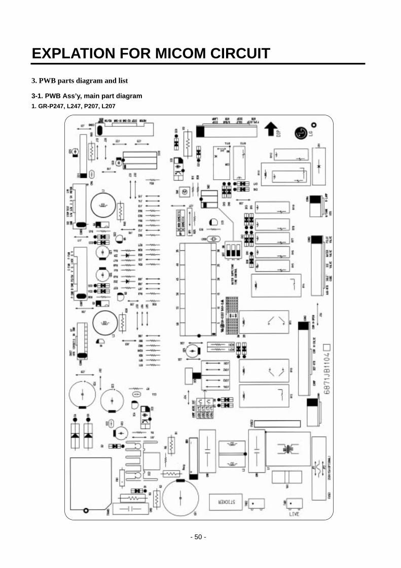
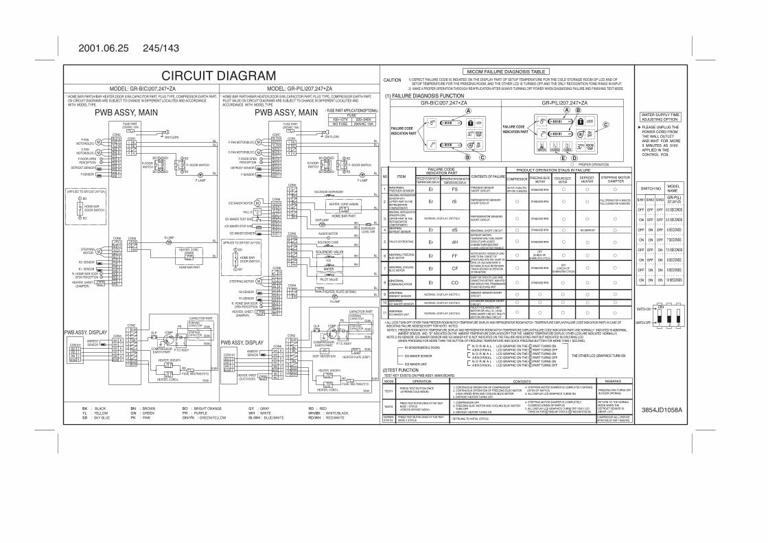
3. PWB parts diagram and list
3-1. PWB Ass’y, main part diagram1. GR-P247, L247, P207, L207
EXPLATION FOR MICOM CIRCUIT
- 50 -

3-2. Parts list1. GR-P247, L247, P207, L207
EXPLATION FOR MICOM CIRCUIT
- 52 -

EXPLATION FOR MICOM CIRCUIT
- 53 -
WATERSUPPLY
S/W

3-3. DISPLAY ASSY part diagram1. GR-P247, L247, P207, L207
EXPLATION FOR MICOM CIRCUIT
- 56 -
DOUBLE SIDE TAPE
SPREAD SHEET

3-4. DISPLAY circuit diagram1. GR-P247, L247, P207, L207
- 58 -
Parts without ( ) mark means SMD parts.
Reception
Transmission

4. PWB circuit diagram - PWB circuit diagram may vary a little bit depending on actual condition.
1. GR-P247, L247, P207, L207
EXPLATION FOR MICOM CIRCUIT
- 60 -
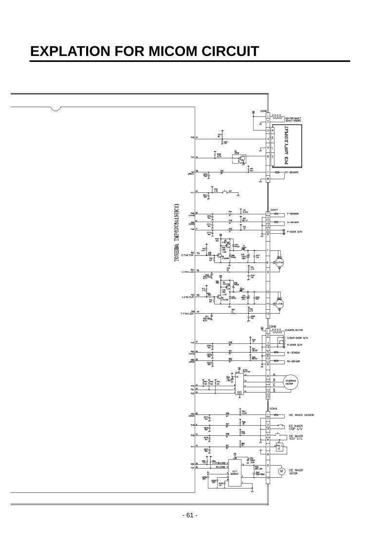
EXPLATION FOR MICOM CIRCUIT
- 61 -

1. TROUBLE SHOOTING
TROUBLE DIAGNOSIS
- 72 -
CLAIMS. CAUSES AND CHECK POINTS. HOW TO CHECK
1. Faulty start1) No power on outlet.2) No power on cord.
3) Shorted start circuit.
4) During defrost.
* Measuring instrument :Multi tester
Check the voltage.If the voltage is within ±85%of the rated voltage, it is OK.
Check the terminalmovement.
Check both terminals ofpower cord.Power conducts : OK.No power conducts : NG
Check both terminals ofO.L.P.If power conducts : OK.If not : NG.
Check the resistance of bothterminals.At normal temperature 6 :OK.If disconnected : ∞.
Bad connection between adapter and outlet. (faulty adapter)The Inner diameter of adapter.The distance between holes.The distance between terminals.The thickness of terminal.
Bad connection between plug and adapter (faulty plug).The distance between pins.Pin outer diameter.
No power onpower cord.
O.L.P is off.
No electric power on compressor. - Faulty compressor.
Faulty PTC.
Disconnected copper wire.
Internal electrical short.
Faulty terminal contact.
Disconnected.
Capacity of O.L.P is small.
Characteristics of O.L.P is bad.
Bad connection.
Power is disconnected.
Inner Ni-Cr wire blows out.Bad internal connection.Faulty terminal caulking (Cu wire is cut).Bad soldering.
Weak connection.Short inserted cord length.Worn out tool blade.
Loose contact.- Large distance betweenmale terminal.
- Thin female terminal.
Terminal disconnected.
Bad sleeve assembly.
Power cord is disconnected.
Faulty soldering.
Start automatic defrost.Cycle was set at defrost when the refrigeratorwas produced.
Power does not conduct. - Damage.
Bad characteristics. - Initial resistance is big.
Bad connection withcompressor.
Bad terminal connection.
Too loose.Assembly is not possible.

TROUBLE DIAGNOSIS
- 73 -
CLAIMS. CAUSES AND CHECK POINTS. HOW TO CHECK
2. No cooling. 2) Refrigeration system is clogged. Check the cloggedevaporator by heating (assoon as the cracking soundbegins, the evaporator startfreezing)
The evaporator does not coolfrom the beginnig (no evideceof misture attached).The evaporator is the sameas before even heat isapplied.
Moistureclogged.
No electricpower ontherm-ostat.
Weld jointclogged.
Drier cloggeing.
Foreign material clogging.
Residual moisturein the evaporator.
Residual moisture.
Insufficient driercapacity.
Residual moisture in pipes.
Moisture penetration - Leave it in the air. - Moisture penetration.into the refrigeration oil.
Caps are missed.
Air blowing.
During transportation.During work.
Not performed.Performed.
Too short time.Low air pressure.Less dry air.
Air Blowing.
Leave it in the air.
Caps are missed.
Short pipe insert.
Pipe gaps.
Too much solder.
Too large.Damaged pipes.
Not dried in the compressor.Elapsed more than 6 months after dryingCaps are missed.No pressure when it is open.
During rest time.
After work.
Compressor cap is disconnected.Foreign materials are in the pipe.
Not performed.Too short.Impossible moistureconfirmation.Low air pressure.
Dry drier - Drier temperature.
Leave it in the air.
The capillary tube inserted depth. - Too much.
Capillary tube melts. - Over heat.
Clogged with foreign materials.
Reduced cross section by cutting. - Squeezed.
Desiccant powder.Weld oxides.Drier angle.
Check on packagecondition.Good storage afterfinishing.
TROUBLE DIAGNOSIS
- 74 -
CLAIMS. CAUSES AND CHECK POINTS. HOW TO CHECK
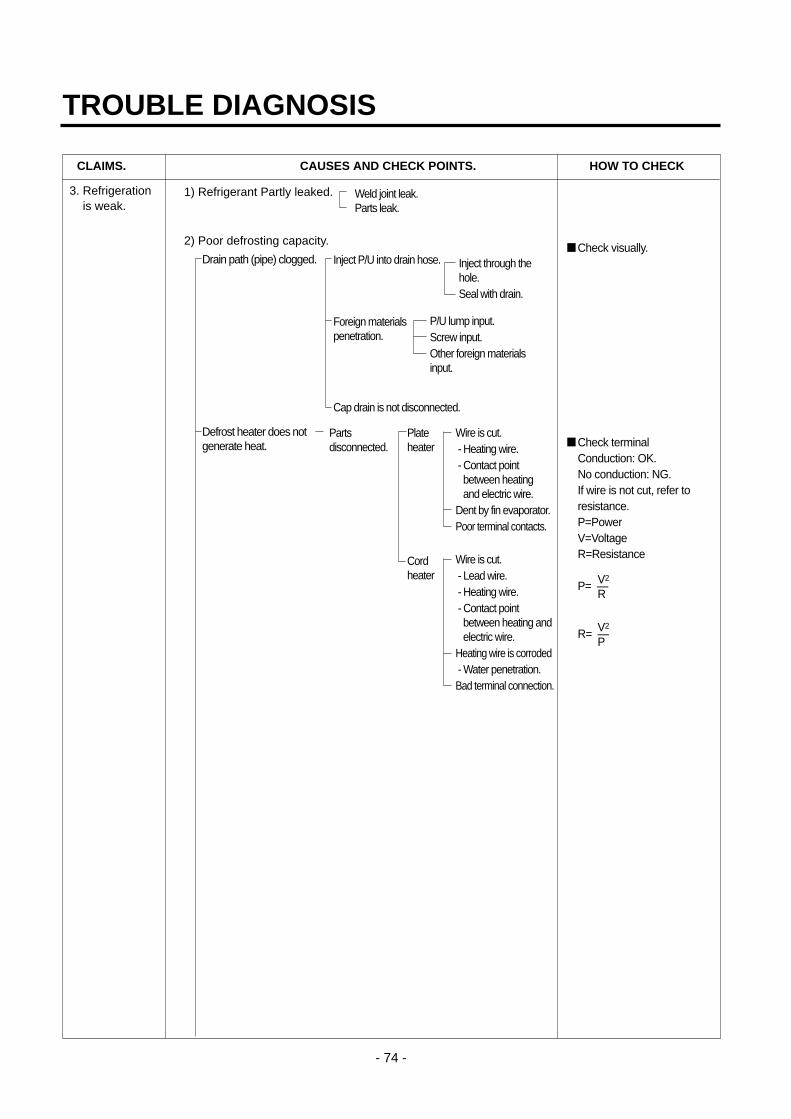
3. Refrigeration is weak.
Plateheater
Cordheater
1) Refrigerant Partly leaked.
2) Poor defrosting capacity.
Drain path (pipe) clogged.
Defrost heater does not generate heat.
Weld joint leak.Parts leak.
Inject P/U into drain hose.
Foreign materialspenetration.
Cap drain is not disconnected.
Inject through thehole.Seal with drain.
P/U lump input.Screw input.Other foreign materialsinput.
Parts disconnected.
Wire is cut.- Heating wire.- Contact pointbetween heatingand electric wire.
Dent by fin evaporator.Poor terminal contacts.
Wire is cut.- Lead wire.- Heating wire.- Contact pointbetween heating andelectric wire.
Heating wire is corroded- Water penetration.Bad terminal connection.
Check visually.
Check terminal Conduction: OK.No conduction: NG.If wire is not cut, refer toresistance.P=PowerV=VoltageR=Resistance
V2P= —
R
V2R= —
P

- 75 -
TROUBLE DIAGNOSIS
CLAIMS. CAUSES AND CHECK POINTS. HOW TO CHECK
3. Refrigeration is weak.
3) Cooling air leak.
4) No cooling air circulation.
Residualfrost.
No automatic defrosting.
Defrost does not return.
Bad gasket adhestion
Door sag.
Faulty fan motor.
Weak heat from heater.
Bad heater assembly.
Too short defrosting time. Defrost Sensor.
- Faulty characteristics.
Seat-D(missing, location. thickness).
Structural fault. Gasket gap.
Air inflow through the fan motor.
Bad insulation of case door.
Sheath Heater - rated.Heater plate - rated.Heater cord-L - rated.
Heater plate
Heater cord-L
Gap.Bad attachment.Contraction.
Bad adhesion.Weak binding force at hinge.
Fan motor.
Door switch.
Self locked.Wire is cut.Bad terminal contact.
Contact distance.Button pressure.Melted contact.Contact.
Poor doorattachment.Door liner(dimension).Contraction innerliner.Misalignment.Bad terminalconnection.P/U liquid leak.
Faults.
Refrigerator and freezer switch reversed.Button is not pressed.
No contact to drain.Loosened stopper cord.
Not contact to theevaporator pipe.Location of assembly(top and middle).
Check the fan motorconduction: OK.No conduction: NG.

TROUBLE DIAGNOSIS
- 76 -
CLAIMS. CAUSES AND CHECK POINTS. HOW TO CHECK
3. Refrigeration is weak.
4) No cooling air circulation.
5) Compressor capacity.
6) Refrigerant too much or too little.
7) Continuous operation- No contact of temperature controller. - Foreign materials.
8) Damper opens continuously.Foreign materials jammed.
Failed sensor. - Position of sensor.Characteristics of damper.
9) Food storing place. - Near the outlet of cooling air.
Faulty fan motor.
Small cooling airdischarge.
Fan is constrained.
Insufficientmotor RPM
Faulty fan.
Shorud. Bent.
Ice and foreign materials on rotating parts.
Fan shroud contact. - Clearance.Damping evaporator contact.Accumulated residual frost.
Fan misuse.Bad shape.Loose connection. - Not tightly connected.Insert depth.
Rating misuse.Small capacity.Low valtage.
Malfunction of charging cylinder.Wrong setting of refrigerant.Insufficient compressor. - Faulty compressor.
Fan overload. - Fan misuse.Bad low termperature RPM characteristics.Rated power misuse.Low voltage.
P/U liquid dump.EPS water sediment.Screw.
Bad characteristics of its own temperatue.Parts misuse.Charge of temperature - Impact.characteristics.
Check visually afterdisassembly.
Check visually afterdisassembly.
TROUBLE DIAGNOSIS
- 77 -
CLAIMS. CAUSES AND CHECK POINTS. HOW TO CHECK
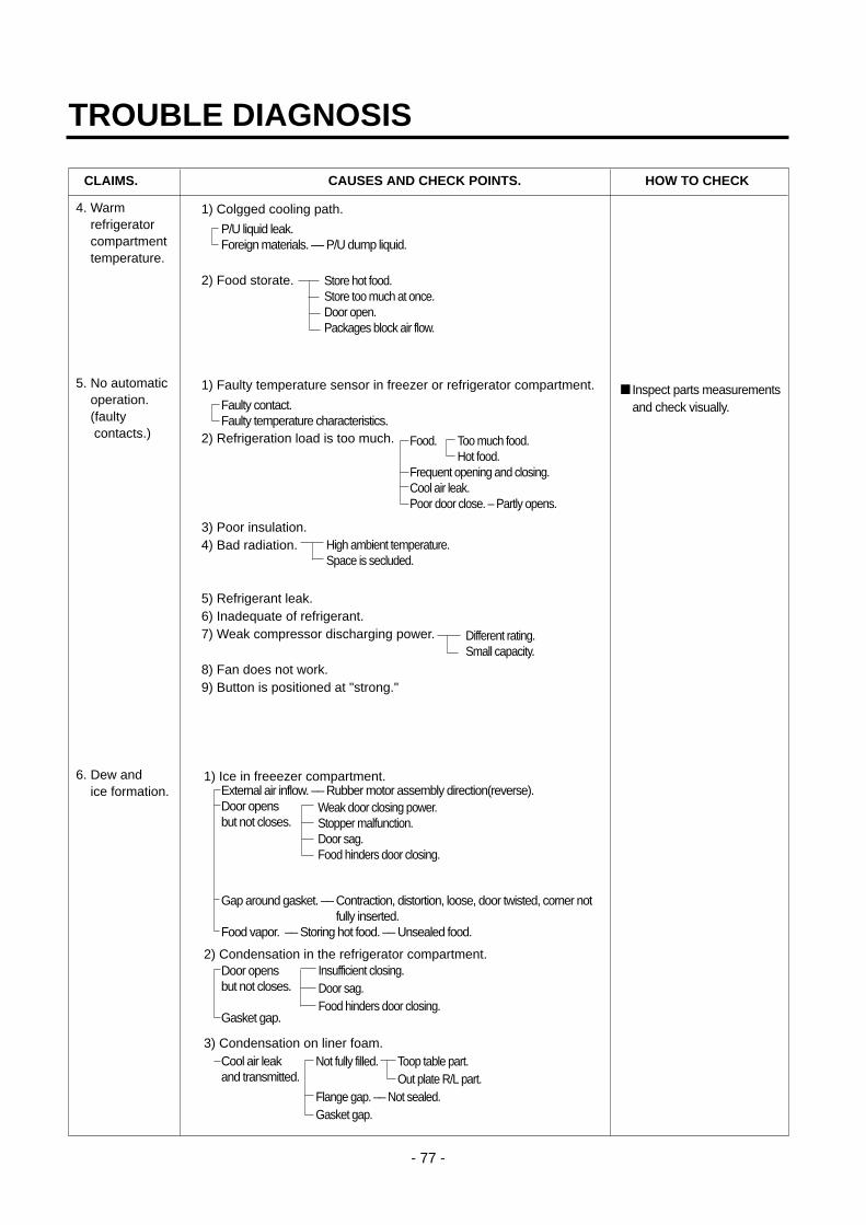
4. Warmrefrigeratorcompartmenttemperature.
5. No automaticoperation.(faulty contacts.)
6. Dew and ice formation.
1) Colgged cooling path.
2) Food storate.
1) Faulty temperature sensor in freezer or refrigerator compartment.
2) Refrigeration load is too much.
3) Poor insulation.4) Bad radiation.
5) Refrigerant leak.6) Inadequate of refrigerant.7) Weak compressor discharging power.
8) Fan does not work.9) Button is positioned at "strong."
1) Ice in freeezer compartment.
2) Condensation in the refrigerator compartment.
3) Condensation on liner foam.
P/U liquid leak.Foreign materials. –– P/U dump liquid.
Faulty contact.Faulty temperature characteristics.
External air inflow. –– Rubber motor assembly direction(reverse).Door opens but not closes.
Gap around gasket. –– Contraction, distortion, loose, door twisted, corner notfully inserted.
Food vapor. –– Storing hot food. –– Unsealed food.
Door opensbut not closes.
Gasket gap.
Cool air leakand transmitted.
High ambient temperature.Space is secluded.
Different rating.Small capacity.
Store hot food.Store too much at once.Door open.Packages block air flow.
Food.
Frequent opening and closing.Cool air leak.Poor door close. – Partly opens.
Too much food.Hot food.
Weak door closing power.Stopper malfunction.Door sag.Food hinders door closing.
Insufficient closing.Door sag.Food hinders door closing.
Toop table part.Out plate R/L part.
Not fully filled.
Flange gap. –– Not sealed.Gasket gap.
Inspect parts measurementsand check visually.

TROUBLE DIAGNOSIS
- 78 -
CLAIMS. CAUSES AND CHECK POINTS. HOW TO CHECK
6. Dew and ice formation.
7. Sounds
4) Dew on door.Dew on the duct door. - Duct door heater is cut.Dew on the dispense recess.
Dew on the door surface. Not fully filled. Surface.Cormer.
P/U liquid contraction.
Dew on thegasket surface.
5) Water on the floor.Dew in the refrigerator compartment.Defrosted water overflows. Clogged discharging hose.Discharging hose Evaporation tray located at wrong place.location.Tray drip. Damaged.
Breaks, holes.Small Capacity.
Position of drain.
1) Compressor compartment operating sounds.Compressor sound Sound from machine itself.inserted. Sound from vibration.
Restrainer.Rubber Too hard.seat. Distorted.
Aged.Burnt.
Stopper. Bad Stopper Not fitassembly. (inner
diameterof stopper).Tilted.Not
Compressor base not connected.Bad welding compressor stand(fallen).Foreign materials in the compressor compartment.
O.L.P. sound. Chattering sound.Insulation paper vibration.
Capacitor noise. Pipe contacts each other. – Narrow interval.Pipe sound. No vibration damper. Damping rubber-Q.
Damping rubber-S.Capillary tube unattached.
Recess Heater is cut.Duct door is open. / Foreign material clogging.
Bad wing adhesion. Wing sag(lower part).Door liner shape mismatch.
Corner. Too much notch.Broken.
Home Bar heater is cut.
Liquid shortage.Liquid leak.

TROUBLE DIAGNOSIS
- 79 -
CLAIMS. CAUSES AND CHECK POINTS. HOW TO CHECK
7. Sounds 1) Compressor compartment operating sounds.Transformer sound.
Drip tray vibration sound.
Back cover machine sound.
Condenser drain sound.
2) Freezer compartment sounds.Fan motor sound.
Sounds from fancontact.
Unbalance fan sounds.
Motor shaftcontact sounds.
Resonance.Evaporator noise.
3) Bowls and bottles make contact on top shelf.
4) Refrigerator roof contact.
5) Refrigerator side contact.
6) Insufficient Lubricants on door hinge.
Its own fault. –– Core gap.Bad connection. –– Correct screw connection.
Bad assembly.Distortion.Foreign materials inside.
Bad connection.Partly damaged.
Not connected.Bad pipe caulking.
Normal operating sound.Vibration sound. Aged rubber seat.
Bad torque for assembling motorbracket.
Fan guide contact.Shroud burr contact.Damping evaporator contact.Residual frost contact.
Unbalance.
Ice on the fan. –– Air intake (opposite to motorrubber assembly.)
Supporter disorted.Tilted during motor assembly.
Evaporator pipe contact. –– No damping evaporator.Sound from refrigerant. –– Stainless steel pipe shape in
accumulator.Sound from fin evaporator and pipe during expansionand contraction.
Poor treatment Cord heater.Narrow evaporator interval.
Surface machining conditions.Fan distortion.Misshappen.Burr.

TROUBLE DIAGNOSIS
- 80 -
CLAIMS. CAUSES AND CHECK POINTS. HOW TO CHECK
8. Faulty lamp(freezer andrefrigeratorcompartment).
9. Faulty internal voltage(short).
1) Lamp problem. Filament blows out.Glass is broken.
2) Bad lamp assembly. Not inserted.Loosened by vibration.
3) Bad lamp socket.Disconnection. Bad soldering.
Bad rivet contact.Short. Water penetration. Low water
level in tray.
Bad elasticity of contact.Bad contact(corrosion).
4) Door switch. Its own defect.Refrigerator and freezer switch is reversed.Travlel distance.Bad connection.Bad terminal contact.P/U liquid leak..
1) Lead wire is damaged.Wire damage when assembling P.T.C. Cover.Outlet burr in the bottom plate.Pressed by cord heater. lead wire, evaporator pipe.
2) Exposed terminal.Compressor Compartment terminal. - Touching other
components.Freezer compartment terminal. - Touching evaporator pipe.
3) Faulty parts.Transformer. Coil contacts cover.
Welded terminal parts contact cover.Compressor. Bad coil insulation.Plate heater.Melting fuse. Sealing is broken. Moisture penetration.Cord heater. Pipe damaged. Moisture penetration.
Bad sealing.Sheath heater.
Connect conduction andnon-conduction parts andcheck with tester. Conduction: NG.Resistance∞: OK.

TROUBLE DIAGNOSIS
- 81 -
CLAIMS. CAUSES AND CHECK POINTS. HOW TO CHECK
10. Structure, appearanceand others.
1) Door foam.Sag.
Noise duringoperation.
Malfunction.
2) Odor.Temperature of refrigeratorcompartment.
Deodorizer.
Food Storage.
Others.
Weak torque ofhinge connection.
Weak gasketadhesion.Fixed tape.
Hinge interference.
Not closed Interference between door liner and inner liner.Refrigeratorcompartment is opened when freezercompartment is closed (faulty stopper).
High. Faulty damper control.Button is set at "weak".Door is open (interference byfood).
No deodorizer.Poor capacity.
Seal condition.Store special odorous food.Long term storage.
Odors from chemical procucts.
Bigger door foam.Hinge-Pin tilted-Poor flatness.No washer.No grease and not enoughquantity.
Stopper worn out.Bad freezer compartment doorassembly.No stopper.
Bolt is loosened duringtransportaion.Not tightly fastened.Screw worn out .Adhesion surface.
Not well fixed.

2. F
ault
s
2-1.
Po
wer
2-2.
Co
mp
ress
or
TROUBLE DIAGNOSIS
- 82 -
Pro
ble
ms
Cau
ses
Ch
ecks
Mea
sure
sR
emar
ks
No
pow
er o
n -
Pow
er c
ord
cut.
- C
heck
the
volta
ge w
ith te
ster
.-R
epla
ce th
e co
mpo
nent
s.
outle
t.-
Fau
lty c
onne
ctor
inse
rtio
n.-
Che
ck v
isua
lly.
-Rec
onne
ct th
e co
nnec
ting
part
s.
- F
aulty
con
nect
ion
betw
een
plug
- C
heck
vis
ually
.-
Rec
onne
ct th
e co
nnec
ting
part
s.
and
adap
ter.
Fus
e bl
ows
out.
- S
hort
circ
uit b
y w
rong
con
nect
ion.
- C
heck
the
fuse
with
test
er-
Fin
d an
d re
mov
e th
e ca
use
of
- R
epla
ce w
ith r
ated
- Lo
w v
olta
ge p
rodu
cts
are
or v
isua
lly.
prob
lem
(ex.
sho
rt, h
igh
volta
ge,
fuse
afte
r co
nfirm
ing
conn
ecte
d to
hig
h vo
ltage
.-
Che
ck th
e in
put v
olt a
re w
ith te
ster
low
vol
tage
).
its s
peci
ficat
ion.
- S
hort
circ
uit b
y in
sect
s.(b
etw
een
pow
er c
ord
and
prod
ucts
).-
Rep
lace
with
rat
ed fu
se.
- E
lect
ricity
leak
age.
- C
heck
the
resi
stan
ce o
f pow
er c
ord
If
fuse
blo
wns
out
- H
igh
volta
ge.
with
test
erf (
if it
is 0
Ω, i
t is
shor
ted)
.fr
eque
ntly
, rec
onfir
m
- S
hort
circ
uit o
f com
pone
nts
the
caus
e an
d pr
even
t.
(tra
ckin
g du
e to
moi
stur
e an
d du
st
pene
trat
ion)
.
Pro
ble
ms
Cau
ses
Ch
ecks
Mea
sure
sR
emar
ks
Com
pres
sor
- F
aulty
PT
C.
- C
heck
the
resi
stan
ce.
- If
resi
stan
ce is
infin
ite, r
epla
ce it
does
not
V
laue
:∞is
def
ectiv
e.w
ith n
ew o
ne.
oper
ate.
- If
it is
not
infin
ite, i
t is
norm
al.
- C
heck
oth
er p
arts
.
- C
ompr
esso
r is
froz
en.
- If
com
pres
sor
asse
mbl
y pa
rts
are
- D
urin
g fo
rced
ope
ratio
n:
norm
al(c
apac
itor,
PT
C, O
LP),
-
Ope
rate
s: C
heck
oth
er p
arts
.
appl
y po
wer
dire
ctly
to th
e -
Not
ope
rate
: Rep
lace
the
froz
en
com
pres
sor
to fo
rce
oper
atio
n.co
mpr
esso
r w
ith n
ew o
ne, w
eld,
evac
uate
, and
rec
harg
e re
frig
eran
t.
OLP
It
sta
rts
as s
oon
as it
is•
Ref
er to
wel
d re
pair
proc
edur
es.
cont
acte
d.
Aux
iliar
y w
indi
ng
Mai
n w
indi
ng
Pow
er

2-3.
Tem
per
atu
reTROUBLE DIAGNOSIS
- 83 -
Pro
ble
ms
Cau
ses
Ch
ecks
Mea
sure
sR
emar
ks
Hig
h P
oor
cool
air
circ
ulat
ion
due
to fa
ulty
- Lo
ck –
– C
heck
res
ista
nce
with
a
- R
epla
ce fa
n m
otor
.
tem
pera
ture
fan
mot
or.
test
er.
in th
e fr
eeze
r0Ω
: sho
rt.
com
part
men
t.∞
Ω: c
ut.
- R
econ
nect
and
rei
nser
t.
- R
otat
e ro
tor
man
ually
and
che
ck
rota
tion.
- W
ire is
cut
.
- B
ad te
rmin
al c
onta
ct: C
heck
-
Mai
ntai
n cl
eara
nce
and
rem
ove
ice
term
inal
vis
ually
.(R
epai
r an
d/or
rep
lace
shr
oud
if fa
n
- F
an c
onst
rain
t. –
Fan
shr
oud
is c
onst
rain
ed b
y sh
roud
cont
act:
Con
firm
defo
rmat
ion)
.
visu
ally
.
– F
an ic
ing:
Con
firm
vis
ually
.
Fau
lty fa
n m
otor
due
to fa
ulty
doo
r -
Iced
but
ton
(fau
lty)
oper
atio
n:-
Con
firm
icin
g ca
uses
and
rep
air.
switc
h op
erat
ion.
Pre
ss b
utto
n to
che
ck-
Rep
lace
doo
r sw
itch.
- F
aulty
but
ton
pres
sure
and
con
tact
:
Pre
ss b
utto
n to
che
ck o
pera
tion.
- D
oor
cann
ot p
ress
doo
r sw
itch
- D
oor
sag:
fix
door
.
butto
n: C
heck
vis
ually
.-
Doo
r lin
er b
ent:r
epla
ce d
oor
or
atta
ch s
heet
s.
Bad
rad
iatio
n co
nditi
ons
in
- C
heck
the
clea
ranc
e be
twee
n th
e -
Kee
p cl
eara
nce
betw
een
- T
he fa
n m
ay b
e
com
pres
sor
com
part
men
t.re
frig
erat
or a
nd w
all (
50 m
m in
re
frig
erat
or a
nd w
alls
(m
inim
um
brok
en if
cle
anin
g
min
imum
).50
mm
).pe
rfor
ms
whi
le th
e
- C
heck
dus
t on
the
grill
in
- R
emov
e du
st a
nd c
onta
min
ants
re
frig
erat
or is
on.
com
pres
sor
com
part
men
t.fr
om g
rill f
or e
asy
heat
rad
iatio
n.
- C
heck
dus
t on
the
coils
con
dens
er.
- R
emov
e th
e du
st w
ith v
acuu
m
clea
ner
from
the
coils
con
dens
er
whi
le th
e re
frig
erat
or is
off.
2-4.
Co
olin
gTROUBLE DIAGNOSIS
- 84 -
Pro
ble
ms
Cau
ses
Ch
ecks
Mea
sure
sR
emar
ks
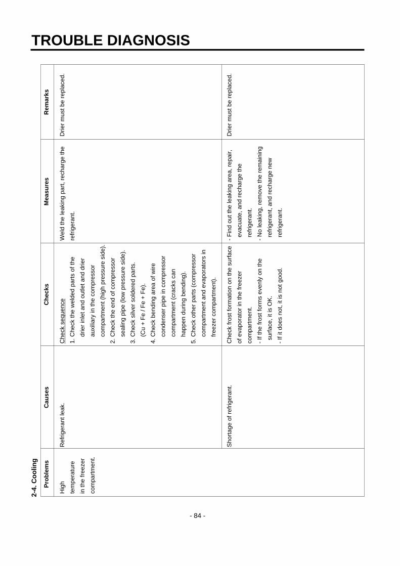
Hig
h R
efrig
eran
t lea
k.C
heck
seq
uenc
eW
eld
the
leak
ing
part
, rec
harg
e th
eD
rier
mus
t be
repl
aced
.
tem
pera
ture
1. C
heck
the
wel
ded
part
s of
the
refr
iger
ant.
in th
e fr
eeze
rdr
ier
inle
t and
out
let a
nd d
rier
com
part
men
t.au
xilia
ry in
the
com
pres
sor
com
part
men
t (hi
gh p
ress
ure
side
).
2. C
heck
the
end
of c
ompr
esso
r
seal
ing
pipe
(lo
w p
ress
ure
side
).
3. C
heck
silv
er s
olde
red
part
s.
(Cu
+ F
e / F
e +
Fe)
.
4. C
heck
ben
ding
are
a of
wire
cond
ense
r pi
pe in
com
pres
sor
com
part
men
t (cr
acks
can
happ
en d
urin
g be
ndin
g).
5. C
heck
oth
er p
arts
(co
mpr
esso
r
com
part
men
t and
eva
pora
tors
in
free
zer
com
part
men
t).
Sho
rtag
e of
ref
riger
ant.
Che
ck fr
ost f
orm
atio
n on
the
surf
ace
- F
ind
out t
he le
akin
g ar
ea, r
epai
r,D
rier
mus
t be
repl
aced
.
of e
vapo
rato
r in
the
free
zer
evac
uate
, and
rec
harg
e th
e
com
part
men
t.re
frig
eran
t.
- If
the
fros
t for
ms
even
ly o
n th
e -
No
leak
ing,
rem
ove
the
rem
aini
ng
surf
ace,
it is
OK
.re
frig
eran
t, an
d re
char
ge n
ew
- If
it do
es n
ot, i
t is
not g
ood.
refr
iger
ant.
TROUBLE DIAGNOSIS
- 85 -
Pro
ble
ms
Cau
ses
Ch
ecks
Mea
sure
sR
emar
ks
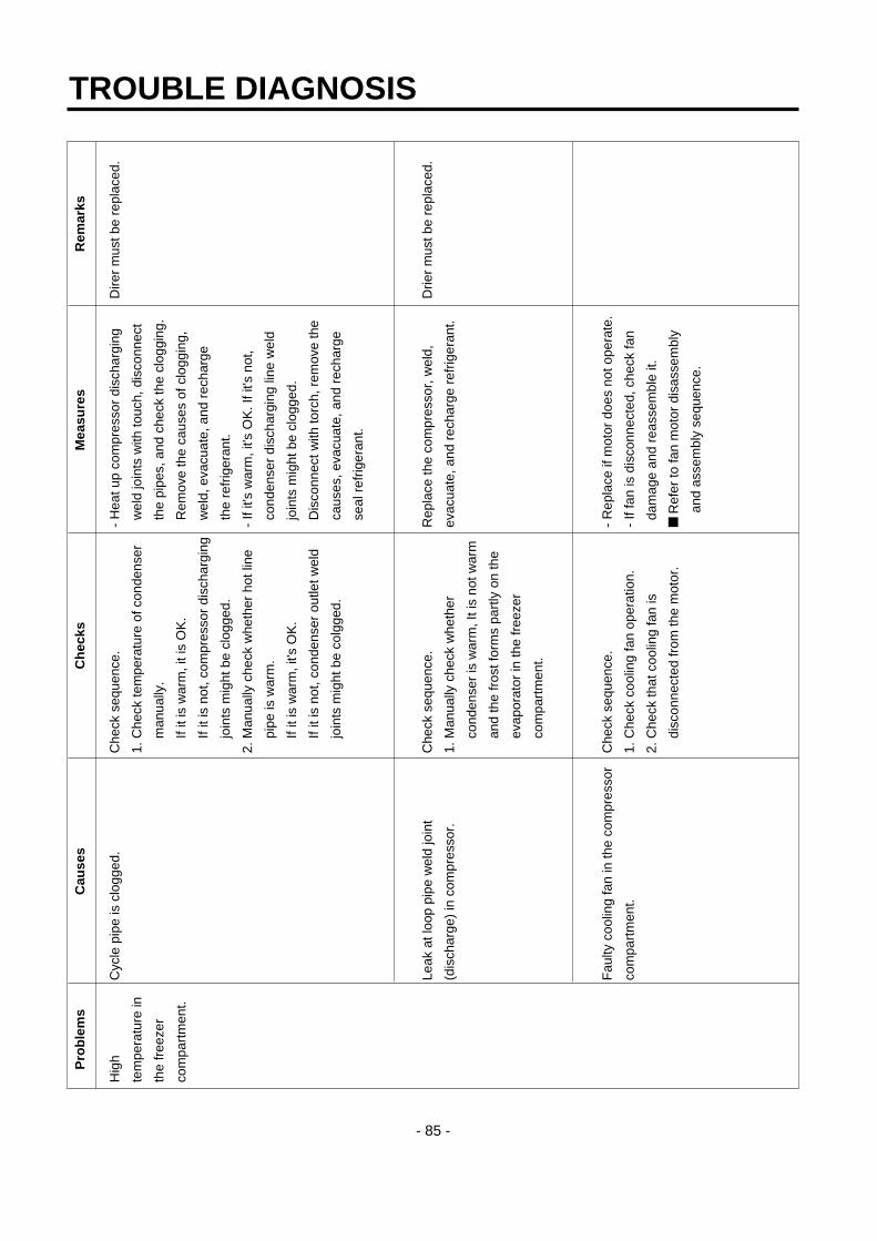
Hig
h C
ycle
pip
e is
clo
gged
.C
heck
seq
uenc
e.-
Hea
t up
com
pres
sor
disc
harg
ing
Dire
r m
ust b
e re
plac
ed.
tem
pera
ture
in1.
Che
ck te
mpe
ratu
re o
f con
dens
erw
eld
join
ts w
ith to
uch,
dis
conn
ect
the
free
zer
man
ually
.th
e pi
pes,
and
che
ck th
e cl
oggi
ng.
com
part
men
t.If
it is
war
m, i
t is
OK
.R
emov
e th
e ca
uses
of c
logg
ing,
If it
is n
ot, c
ompr
esso
r di
scha
rgin
gw
eld,
eva
cuat
e, a
nd r
echa
rge
join
ts m
ight
be
clog
ged.
the
refr
iger
ant.
2. M
anua
lly c
heck
whe
ther
hot
line
- If
it's
war
m, i
t's O
K. I
f it's
not
,
pipe
is w
arm
.co
nden
ser
disc
harg
ing
line
wel
d
If it
is w
arm
, it's
OK
.jo
ints
mig
ht b
e cl
ogge
d.
If it
is n
ot, c
onde
nser
out
let w
eld
Dis
conn
ect w
ith to
rch,
rem
ove
the
join
ts m
ight
be
colg
ged.
caus
es, e
vacu
ate,
and
rec
harg
e
seal
ref
riger
ant.
Leak
at l
oop
pipe
wel
d jo
int
Che
ck s
eque
nce.
Rep
lace
the
com
pres
sor,
wel
d,
Drie
r m
ust b
e re
plac
ed.
(dis
char
ge)
in c
ompr
esso
r.1.
Man
ually
che
ck w
heth
er
evac
uate
, and
rec
harg
e re
frig
eran
t.
cond
ense
r is
war
m, I
t is
not w
arm
and
the
fros
t for
ms
part
ly o
n th
e
evap
orat
or in
the
free
zer
com
part
men
t.
Fau
lty c
oolin
g fa
n in
the
com
pres
sor
Che
ck s
eque
nce.
- R
epla
ce if
mot
or d
oes
not o
pera
te.
com
part
men
t.1.
Che
ck c
oolin
g fa
n op
erat
ion.
- If
fan
is d
isco
nnec
ted,
che
ck fa
n
2. C
heck
that
coo
ling
fan
is
dam
age
and
reas
sem
ble
it.
disc
onne
cted
from
the
mot
or.
R
efer
to fa
n m
otor
dis
asse
mbl
y
and
asse
mbl
y se
quen
ce.

2-5.
Def
rost
ing
fai
lure
TROUBLE DIAGNOSIS
- 86 -
Pro
ble
ms
Cau
ses
Ch
ecks
Mea
sure
sR
emar
ks
No
defr
ostin
g.H
eate
r do
es n
ot g
ener
ate
heat
as
1. C
heck
the
resi
stan
ce o
f hea
ter.
Hea
ting
wire
is s
hort
and
wire
is c
ut.
Sea
l the
lead
wire
with
the
heat
ing
wire
is c
ut o
r th
e ci
rcui
t0Ω
: Sho
rt. ∞
Ω: C
ut.
• P
arts
rep
lace
men
t: R
efer
to p
arts
insu
latio
n ta
pe a
nd h
eat
is s
hort
ed.
Ten
s to
thou
sand
s Ω
: OK
.ex
plan
atio
ns.
cont
ract
ion
tube
if th
e cu
t
1) H
eatin
g w
ire is
dam
aged
whe
n 2.
Che
ck th
e re
sist
ance
bet
wee
n le
ad w
ire is
acc
essi
ble
to
inse
rtin
g in
to th
e ev
apor
ator
.ho
usin
g te
rmin
al a
nd h
eate
rre
pair.
2) L
ead
wire
of h
eate
r is
cut
.su
rfac
e.
3) H
eatin
g w
ire a
t lea
d w
ire c
onta
cts
0Ω: S
hort
. ∞Ω
: Cut
.
is c
ut.
Ten
s to
thou
sand
s Ω
: Sho
rt.
Suc
king
duc
t and
dis
char
ging
hol
e 1.
Con
firm
fore
ign
mat
eria
ls. I
n ca
se1)
Pus
h ou
t im
purit
ies
by in
sert
ing
are
clog
ged:
of ic
e, in
sert
the
copp
er li
ne
copp
er w
ire.(
Tur
n of
f mor
e th
an
1. Im
purit
ies.
thro
ugh
the
hole
to c
heck
.3h
ours
and
pou
r in
hot
wat
er if
2. Ic
e.2.
Put
hot
wat
er in
to th
e dr
ain
fros
t is
seve
re.)
(che
ck d
rain
s ou
tsid
e).
2) P
ut in
hot
wat
er to
mel
t dow
n fr
ost.
3) C
heck
the
wat
er o
utle
t.
4) P
ush
the
heat
er p
late
to s
ucki
ng
duct
man
ually
and
ass
embl
e th
e
disc
onne
cted
par
ts.
Gap
bet
wee
n S
ucki
ng d
uct a
nd1.
Con
firm
in th
e S
ucki
ng d
uct.
1) T
urn
off t
he p
ower
, con
firm
Hea
ter
plat
e(Ic
e in
the
gap)
.im
purit
ies
and
ice
in th
e ga
p, a
nd
supp
ly h
ot w
ater
unt
il th
e ic
e in
the
gap
mel
ts d
own.
2) P
ush
the
Hea
ter
plat
e to
dra
in
botto
m w
ith h
and
and
asse
mbl
e
the
disc
onne
cted
par
ts.
Wro
ng h
eate
r ra
ting
(or
wro
ng
1. C
heck
hea
ter
labe
l.F
aults
:rep
lace
.
asse
mbl
y).
2. C
onfir
m th
e ca
paci
ty a
fter
- H
ow to
rep
lace
: Ref
er to
mai
n pa
rts.
subs
titut
ing
the
resi
stan
ce v
alue
into
the
form
ula.
(V: R
ated
vol
tage
of u
ser c
ount
ry)
(R: R
esis
tanc
e of
test
er[Ω
])
Com
pare
P a
nd la
vel c
apac
ity.
Tole
ranc
e: ±
7%
V2
P=
–– R

TROUBLE DIAGNOSIS
- 87 -
Pro
ble
ms
Cau
ses
Ch
ecks
Mea
sure
sR
emar
ks
No
defr
ostin
gM
eltin
g fu
se b
low
s ou
t.-
Che
ck m
eltin
g fu
se w
ith te
ster
. -
Fau
llty
part
s: p
arts
rep
lace
men
t.
1) L
ead
wire
is c
ut.
If 0Ω
: OK
.-
Che
ck w
ire c
olor
whe
n m
aeas
urin
g
2) B
ad s
olde
ring.
If ∞
Ω: w
ire is
cut
.re
sist
ance
with
a te
ster
.
Ice
in th
e S
ucki
ng d
uct.
1. C
heck
the
inne
r du
ct w
ith m
irror
.1)
Tur
n po
wer
off.
1) Ic
ing
by fo
reig
n m
ater
ials
in th
e2)
Rai
se th
e fr
ont s
ide(
door
sid
e),
duct
.su
ppor
t the
fron
t sid
e le
gs, a
nd le
t
2) Ic
ing
by c
ool a
ir in
flow
thro
ugh
the
ice
mel
t nat
ural
ly. (
If po
wer
is
the
gap
of h
eate
r pl
ate.
on, m
elt t
he fr
ost b
y fo
rced
3) Ic
ing
by th
e ga
p of
hea
ter
plat
e.de
fros
ting.
)
2. C
heck
by
inse
rtin
g so
ft co
pper
3)
Rea
ssem
ble
the
heat
er p
late
.
wire
into
the
duct
(so
ft an
d th
in
copp
er n
ot to
impa
ir he
atin
g w
ire).
Bad
coo
l air
inflo
w a
nd d
isch
arge
, 1.
Tur
n on
pow
er, o
pen
or c
lose
the
1) C
heck
the
faul
ty c
onne
ctor
of
and
bad
defr
ostin
g du
e to
faul
tydo
or, c
heck
that
mot
or fa
n ho
usin
g an
d re
asse
mbl
e w
rong
ly
cont
act a
nd in
sert
ion
(bad
con
nect
orop
erat
es (
If it
oper
ates
, mot
or fa
nas
sem
bled
par
ts.
inse
rtio
n in
to h
ousi
ng o
f hea
ter,
is
OK
).2)
If th
e pa
rts
are
very
dam
aged
,
mel
ting,
fuse
and
mot
or fa
n).
2. D
isco
nnec
t par
ts in
the
refr
iger
ator
rem
ove
the
part
s an
d re
plac
e it
com
part
men
t, ch
eck
the
conn
ectio
nw
ith a
new
one
.
arou
nd th
e ho
usin
g vi
sual
ly,
defr
ost,
and
conf
irm h
eat g
ener
atio
n
on th
e he
ater
. Do
not p
ut h
ands
on
the
shea
th h
eate
r.
3. C
heck
the
part
s w
hich
hav
e fa
ults
desc
ribed
in 1
, 2 (
mec
hani
cal
mod
el: d
isco
nnec
t the
rmos
tat
from
the
asse
mbl
y).

2-6.
Icin
gTROUBLE DIAGNOSIS
- 88 -
Pro
ble
ms
Cau
ses
Ch
ecks
Mea
sure
sR
emar
ks
Icin
g in
the
1) B
ad c
ircul
atio
n of
coo
l air.
- C
heck
the
food
is s
tore
d pr
oper
ly-
Be
acqu
aint
ed w
ith h
ow to
use
.-
Che
ck th
e de
fros
t
refr
iger
ator
-
Clo
gged
inta
ke p
ort i
n th
e (c
heck
dis
char
ge a
nd in
take
por
t -
Sea
ling
on c
onne
ctin
g pa
rts.
rela
ted
part
s if
prob
lem
com
part
men
t.re
frig
erat
or c
ompa
rtm
ent.
are
clog
ged)
.-
Che
ck th
e da
mpe
r an
d re
plac
eis
cau
sed
by fa
ulty
- D
ampe
r ic
ing.
- S
ealin
g is
not
goo
d.-
Che
ck ic
ing
on th
e su
rfac
e of
it
if it
has
defe
cts.
defr
ostin
g.
- P
ipe
icin
g.-
Too
muc
h fo
od is
sto
red
and
clog
sba
ffle
and
cool
air
path
(pi
pe)
afte
r-
Che
ck d
efro
st. (
Afte
r fo
rced
- D
isch
argi
ngth
e di
scha
rge
port
.di
ssem
blin
g th
e co
ntai
ner
box.
defr
ostin
g, c
heck
ice
in th
e
pipe
icin
g.-
Bad
def
rost
ing.
- C
heck
icin
g at
inta
ke p
orts
of
evap
orat
or a
nd p
ipes
.)
free
zer
and
refr
iger
ator
com
part
men
t.
2) F
aulty
doo
r or
ref
riger
ator
- C
heck
gas
ket a
ttach
ed c
ondi
tions
.-
Cor
rect
the
gask
et a
ttach
men
t-
Rep
lace
men
t sho
uld
com
part
men
t.-
Che
ck d
oor
asse
mbl
y co
nditi
ons.
cond
ition
s an
d re
plac
e it.
be d
one
whe
n it
- F
aulty
gas
ket.
- D
oor
asse
mbl
y an
d re
plac
emen
t.ca
nnot
be
repa
ired.
- F
aulty
ass
embl
y.
3) O
verc
oolin
g in
the
refr
iger
ator
- C
heck
ref
riger
ator
com
part
men
t-
Rep
lace
faul
ty p
arts
.
com
part
men
t.is
ove
rcoo
led
(whe
n bu
tton
- F
aulty
dam
per
in th
e re
frig
erat
orpr
esse
d on
"w
eak"
).
com
part
men
t.-
Che
ck p
arts
are
faul
ty.
- F
aulty
MIC
OM
(fa
ulty
sen
sor)
4) B
ad d
efro
stin
g-
Che
ck fr
ost o
n th
e ev
apor
ator
- C
heck
par
ts r
elat
ed to
def
rost
ing.
- M
oist
ure
cann
ot fr
ost
- H
eate
r w
ire is
cut
.af
ter
diss
embl
ing
shro
ud a
nd fa
n-
Che
ck d
efro
stin
g. (
Che
ck ic
e on
the
on th
e ev
apor
ator
but
- D
efec
tive
defr
ost s
enso
r.gr
ille.
evap
orat
or a
nd p
ipe.
)ca
n be
suc
ked
into
the
- D
efro
sing
cyc
le.
- C
heck
ice
on in
take
por
t of f
reez
erre
frig
erat
or, b
eing
and
refr
iger
ator
com
part
men
t.co
nden
sed
and
iced
,
inte
rfer
es w
ith c
ool a
ir
circ
ulat
ion,
and
supp
ress
es s
ublim
atio
n.
5) C
usto
mer
s ar
e n
ot fa
mili
ar w
ith-
Che
ck fo
od in
terf
eres
with
doo
r-
Be
acqu
aint
ed w
ith h
ow to
use
.
this
mac
hine
.cl
osin
g.
- D
oor
open
s.-
Che
ck ic
e on
the
ceili
ngs.
- H
igh
tem
pera
ture
, hig
h m
oist
ure,
and
high
load
.

TROUBLE DIAGNOSIS
- 89 -
Pro
ble
ms
Cau
ses
Ch
ecks
Mea
sure
sR
emar
ks
Ice
in th
e fr
eeze
r 1)
Bad
coo
ling
air
circ
ulat
ion.
- C
heck
food
sto
rage
con
ditio
ns
- B
e ac
quai
nted
with
how
to u
se.
- C
heck
the
part
s re
late
d
com
part
men
t.-
Inta
ke p
ort i
s co
lgge
d in
the
free
zer
visu
ally
.(C
heck
clo
ggin
g at
inta
ke
- C
heck
def
rost
(C
heck
ice
on th
eto
def
rost
ing
if th
e
- S
urfa
ce o
f fan
com
part
men
t.an
d di
scha
rgin
g po
rt o
f coo
ling
air.
)ev
apor
ator
and
pip
es a
fter
forc
edpr
oble
m is
cau
sed
by
grill
e.-
Dis
char
ging
por
t is
Clo
gged
.-
Che
ck fo
od o
ccup
atio
n ra
tio in
de
fros
ting)
.th
e fa
ulty
def
rost
ing.
- W
all o
f fre
ezer
- T
oo m
uch
food
is s
tore
d.vo
lum
e(Le
ss th
an 7
5%).
com
part
men
t.-
Bad
def
rost
ing.
- C
heck
fros
t on
the
evap
orat
or a
fter
- C
ool a
irdi
ssem
blin
g sh
roud
and
fan
grill
e.
disc
harg
ing
port
.-
Che
ck ic
ing
at in
take
por
t of
- B
aske
t(ra
ck)
refr
iger
ator
com
part
men
t.
area
.
- F
ood
surf
ace.
2) B
ad fr
eeze
r co
mpa
rtm
ent d
oor
- C
heck
gas
ket a
ttach
men
t -
Cor
rect
the
gask
et a
ttach
emen
t-
Rep
lace
whe
n it
can
not
- Ic
ing
in th
e-
Fau
lty g
aske
tco
nditi
ons.
cond
ition
s an
d re
plac
e it.
be r
epai
red.
shut
e.-
Fau
lty a
ssem
bly
- C
heck
doo
r as
sem
bly
cond
ition
s.-
Doo
r as
sem
bly
and
repl
acem
ent.
3) O
ver
free
zing
in th
e fr
eeze
r -
Ref
riger
ator
ope
rate
s pu
ll do
wn.
-Rep
lace
def
ectiv
e pa
rts.
com
part
men
t.(C
heck
if it
is o
pera
ted
- F
aulty
MIC
OM
.in
term
itten
tly)
- T
he T
empe
ratu
re o
f fre
ezer
com
part
men
t is
satis
fact
ory,
but
over
free
zing
hap
pens
in th
e
refr
iger
ator
com
part
men
t eve
n
thou
gh th
e no
tch
is s
et a
t "w
eak"
.
4) B
ad d
efro
stin
g.-
Che
ck fr
ost o
n th
e ev
apor
ator
afte
r-
Che
ck p
arts
rel
ated
to d
efro
stin
g.
- H
eate
r w
ire is
cut
.di
ssem
blin
g sh
roud
and
gril
le.
- C
heck
def
rost
ing.
(Che
ck ic
e on
the
- F
aulty
def
rost
sen
sor.
- C
heck
ice
on th
e in
take
por
t in
the
evap
orat
or a
nd p
ipes
afte
r fo
rced
- D
efro
stin
g cy
cle
refr
iger
ator
com
part
men
t.de
fros
ting.
)
5) U
ser
is n
ot fa
mili
ar w
ith h
ow to
-
Che
ck fo
od h
olds
doo
r op
en.
- B
e ac
quai
nted
with
how
to u
se.
use.
- C
heck
ice
on th
e ic
e tr
ay.
- D
oor
open
s.
- H
igh
moi
stur
e fo
od(w
ater
) is
sto
red.

2-7.
So
un
dTROUBLE DIAGNOSIS
- 90 -
Pro
ble
ms
Cau
ses
Ch
ecks
Mea
sure
sR
emar
ks
"Whi
zz"
soun
d1.
Lou
d so
und
of c
ompr
esso
r 1.
1 C
heck
the
leve
l of t
he
1) M
aint
ain
horiz
onta
l lev
el.
oper
atio
n.re
frig
erat
or.
2) R
epla
ce r
ubbe
r an
d se
at if
they
1.2
Che
ck th
e ru
bber
sea
t ar
e sa
gged
and
age
d.
cond
ition
s (s
aggi
ng a
nd a
ging
).3)
Inse
rt r
ubbe
r w
here
han
d co
ntac
t
redu
ces
nois
e in
the
pipe
.
2. P
ipes
res
onat
sou
nd w
hich
is
2.1
Che
ck th
e le
vel o
f pip
es4)
Avo
id p
ipe
inte
rfer
ence
.
conn
ecte
d to
the
com
pres
sor.
conn
ecte
d to
the
com
pres
sor
5) R
epla
ce d
efec
tive
fan
and
fan
and
thei
r in
terf
eren
ce.
mot
or.
2.2
Che
ck r
ubbe
r in
sert
ing
6) A
djus
t fan
to b
e in
the
cent
er o
f
cond
ition
s in
pip
es.
bell
mou
th o
f the
fan
guid
e.
2.3
Tou
ch p
ipes
with
han
ds o
r sc
rew
7) L
eve
a cl
eara
nce
betw
een
-driv
er (
chec
k th
e ch
ange
of
inte
rfer
ing
part
s an
d se
al g
aps
in
soun
d).
the
stru
ctur
es.
8) R
eass
embl
e th
e pa
rts
whi
ch m
ake
3. F
an o
pera
tion
soun
d in
the
free
zer
3.1
Che
ck fa
n in
sert
ion
dept
h an
d so
und.
com
part
men
t.bl
ade
dam
age.
9) L
eave
a c
lear
ance
if e
vapo
rato
r
3.2
Che
ck th
e in
terf
eren
ce w
ith
pipe
s an
d su
ctio
n pi
pe to
uch
stru
ctur
es.
free
zer
shro
ud.
3.3
Che
ck fa
n m
otor
.
3.4
Che
ck fa
n m
otor
rub
ber
inse
rtio
n
and
agin
g co
nditi
ons.
4. F
an o
pera
tion
soun
d in
the
4.1
Sam
e as
fan
conf
irmat
ion
in th
e
com
pres
sor
com
part
men
t.re
frig
erat
or.
4.2
Che
ck d
rip tr
ay le
g in
sert
ion.
4.3
Che
ck th
e sc
rew
fast
enin
g
cond
ition
s at
con
dens
er a
nd
drip
tray
.

TROUBLE DIAGNOSIS
- 91 -
Pro
ble
ms
Cau
ses
Ch
ecks
Mea
sure
sR
emar
ks
Vib
ratio
n so
und.
1. V
ibra
tion
of s
helv
es a
nd fo
ods
in1-
1. R
emov
e an
d re
plac
e th
e
1) R
eass
embl
e th
e vi
brat
ing
part
s
("C
luck
")th
e re
frig
erat
or.
shel
ves
in th
e re
frig
erat
oran
d in
sert
foam
or
cush
ion
whe
re
2. P
ipes
inte
rfer
ence
and
cap
illar
y1-
2. C
heck
ligh
t foo
d an
d co
ntai
ner
vibr
atio
n is
sev
ere.
tube
touc
hing
in th
e co
mpr
esso
r.on
the
shel
ves.
2) L
eave
a c
lear
ance
whe
re p
arts
com
part
men
t.2-
1. T
ouch
pip
es in
the
com
pres
sore
in
terf
ere
with
eac
h ot
her.
3. C
ompr
esso
r st
oppe
r vi
brat
ion.
com
part
men
t with
han
ds.
3) R
educ
e vi
brat
ion
with
rub
ber
4. M
ovin
g w
heel
vib
ratio
n.2-
2 C
heck
cap
illar
y tu
be to
uche
s an
d re
stra
iner
if it
is s
ever
e.
5. O
ther
str
uctu
re a
nd p
arts
co
ver
back
.(e
spec
ially
, com
pres
sor
and
pipe
).
vibr
atio
n.3-
1 C
heck
com
pres
sor
stop
per
4) R
epla
ce c
ompr
esso
r st
oppe
r if
it
vibr
atio
n.vi
btat
es s
ever
ely.
4-1
Che
ck v
ibra
tion
of fr
ont a
nd r
ear
mov
ing
whe
els.
5-1
Tou
ch o
ther
str
uctu
res
and
part
s.
Irre
gula
r so
und.
1. It
is c
ause
d by
hea
t exp
ansi
on1-
1 C
heck
tim
e an
d pl
ace
of s
ound
1)
Exp
lain
the
prin
cipl
es o
f ref
riger
atio
n
("C
lick"
).an
d co
ntra
ctio
n of
eva
pora
tor,
sour
ces.
and
that
the
tem
pera
ture
diff
eren
ce
shel
ves,
and
pip
es in
the
betw
een
oper
atio
n an
d de
fros
ting
refr
iger
ator
.ca
n m
ake
soun
ds.
2) If
eva
pora
tor p
ipe
cont
acts
with
oth
er
stru
ctur
es, l
eave
a c
lear
ance
bet
wee
n
them
(fre
ezer
shr
oud
or in
ner c
ase)
.

TROUBLE DIAGNOSIS
- 92 -
Pro
ble
ms
Cau
ses
Ch
ecks
Mea
sure
sR
emar
ks
Sou
nd "
Bur
ping
"It
happ
ens
whe
n re
frig
eran
t exp
ands
- C
heck
the
soun
d of
refri
gera
nt a
t the
- C
heck
the
rest
rain
er a
ttach
ed o
n th
e
(alm
ost t
he s
ame
at th
e en
d of
cap
illar
y tu
be.
initi
al in
stal
latio
n.ev
apor
ator
and
cap
illar
y tu
be w
eld
as a
nim
als
cryi
ng- C
heck
the
soun
d w
hen
the
refri
gera
tor
join
ts a
nd a
ttach
ano
ther
rest
rain
er.
soun
d).
star
ts o
pera
tion
afte
r for
ced
defro
stin
g.- I
f it i
s co
ntin
uous
and
ser
vere
, ins
ert
- Che
ck th
e re
stra
iner
atta
chm
ent
capi
llary
tube
aga
in (d
epth
:15±
3mm
)
cond
ition
s on
the
evap
orat
or a
nd- F
aste
n th
e ca
pilla
ry tu
be to
suc
tion
capi
llary
tube
wel
d jo
ints
.pi
pes
or d
etac
h in
the
com
pres
sor
com
partm
ent.
- Exp
lain
the
prin
cipl
es o
f fre
ezin
g
cycl
es.
Wat
er b
oilin
g or
It ha
ppen
s w
hen
refri
gera
nt p
asse
s- C
heck
the
soun
d w
hen
com
pres
sor i
s- E
xpla
in th
e pr
inci
ples
of f
reez
ing
cycl
es
flow
ing
soun
d.or
ifice
in a
ccum
ulat
or in
tern
al p
ipes
by
turn
ed o
n.an
d re
frige
rant
flow
ing
phen
omen
on b
y
the
pres
sure
diff
eren
ce b
etw
een
- Che
ck th
e so
und
whe
n co
mpr
esso
r is
inte
rnal
pre
ssur
e di
ffere
nce.
cond
ense
r and
eva
pora
tor.
turn
ed o
ff.- I
f sou
nd is
ser
vere
, wra
p th
e
accu
mul
ator
with
foam
and
rest
rain
er.
Sou
nd o
f whi
stle
Whe
n do
or c
lose
s, th
e in
tern
al p
ress
ure
- Che
ck th
e so
und
by o
peni
ng a
nd
- Bro
aden
the
cap
of d
isch
arge
hos
e fo
r
whe
n do
or
of th
e re
frige
rato
r dec
reas
es s
harp
lycl
osin
g th
e re
frige
rato
r or f
reez
er d
oors
.de
frost
ing
in th
e co
mpr
esso
r
clos
es.
belo
w a
tom
osph
ere
and
suck
s ai
r int
oco
mpa
rtmen
t.
the
refri
gera
tor,
mak
ing
the
whi
stle
- S
eal t
he g
ap w
ith s
eala
nt b
etw
een
out
soun
d.an
d in
ner c
ases
of h
inge
in d
oor.

2-8.
Od
or
TROUBLE DIAGNOSIS
- 93 -
Pro
ble
ms
Cau
ses
Ch
ecks
Mea
sure
sR
emar
ks
Foo
d O
dor.
Foo
d (g
arlic
, kim
chi,
etc)
- C
heck
the
food
is n
ot w
rapp
ed.
- D
ry d
eodo
rizer
in th
e sh
iny
and
- C
heck
the
shel
ves
or in
ner
win
dy p
lace
.
wal
l are
sta
ined
with
food
juic
e.-
Sto
re th
e fo
od in
the
clos
ed
- C
heck
the
food
in th
e vi
nyl w
raps
.co
ntai
ner
inst
ead
of v
inyl
wra
ps.
- C
hedk
food
cle
anlin
ess.
- C
lean
the
refr
iger
ator
and
set
butto
n at
"st
rong
".
Pla
stic
Odo
r.O
dors
of m
ixed
food
and
pla
stic
-
Che
ck w
et fo
od is
wra
pped
with
-
Cle
an th
e re
frig
erat
or.
odor
s.pl
astic
bow
l and
bag
.-
Per
suad
e cu
stom
ers
not t
o us
e
- It
happ
ens
in th
e ne
w r
efrig
erat
or.
plas
tic b
ag o
r w
raps
with
wet
food
or o
doro
us fo
ods.
Odo
r fr
om th
eO
dor
from
the
old
deod
oriz
er.
- C
heck
the
deod
oriz
er o
dors
.-
Dry
the
deod
oriz
er w
ith d
ryer
and
*D
eodo
rizer
: op
tion
deod
oriz
er.
then
in th
e sh
iny
and
win
dy p
lace
.
- R
emov
e an
d re
plac
e th
e
deod
oran
ts.

2-9.
Mic
om
TROUBLE DIAGNOSIS
- 94 -
Pro
ble
ms
Sym
pto
mC
ause
sC
hec
ksM
easu
res
Rem
arks
Bad
PC
B
All
disp
lay
Bad
con
nect
ion
Bad
con
nect
orV
isua
l che
ck o
n co
nnec
tor
Rec
onne
ct
elec
tric
pow
er.
LCD
are
off.
betw
een
Mai
n P
CB
co
nnec
tion
from
mai
n co
nnec
tion.
conn
ecto
r.
and
disp
lay
circ
uit.
PC
B to
dis
play
PC
B.
Def
ectiv
e P
CB
tran
s.P
CB
Tra
ns w
indi
ng is
C
heck
res
ista
nce
of P
CB
Tra
nsR
epla
ce P
CB
Tra
nsA
pplic
able
to
cut.
inpu
t and
out
put t
erm
inal
s w
ithor
PC
B.
mod
el w
ithou
t
PC
B T
rans
tem
pera
ture
a te
ster
. (If
resi
stan
ce is
infin
ity,
disp
ense
r.
fuse
is b
urnt
out
.tr
ans
win
ding
is c
ut).
Def
ectiv
ePC
B e
lect
ricD
efec
tive
regu
lato
r IC
Che
ck v
olta
ge a
t inp
ut/o
utpu
tR
epla
ce r
egul
ator
.R
efer
to e
lect
ric
circ
uit p
arts
.(7
812,
780
5).
term
inal
s.ci
rcui
t in
circ
uit
expl
anat
ion.
PC
B e
lect
ric te
rmin
alC
heck
fuse
in P
CB
ele
ctric
R
epla
ce P
CB
fuse
.
fuse
is b
urnt
out
.te
rmin
al w
ith a
test
er.
ST
R P
arts
are
C
heck
if S
TR
No.
2 a
nd 3
pin
sR
epla
ce p
arts
.A
pplic
able
to
dam
aged
.ar
e cu
t whe
n po
wer
is o
ff.m
odel
with
disp
ense
r.
Abn
orm
al
Bad
con
nect
ion
Lead
Wire
con
nect
ing
Che
ck L
ead
Wire
term
inal
s R
econ
nect
Lea
d
disp
lay
LCD
betw
een
Mai
n P
CB
m
ain
PC
B a
nd d
ispl
ayco
nnec
ting
Mai
n P
CB
and
W
ire a
nd d
irect
ly
oper
atio
nan
d di
spla
y ci
rcui
t.P
CB
is c
ut o
r co
nnec
tor
disp
lay
PC
B w
ith a
test
er.
conn
ect d
efec
tive
term
inal
con
nect
ion
isco
ntac
t ter
min
al to
bad.
Lead
Wire
.
Def
ectiv
e LC
D.
Def
ectiv
e LC
D.
Che
ck if
all
LCD
are
on
whe
n R
epla
ce d
ispl
ay
Ref
er to
dis
play
Mai
n P
CB
Tes
t sw
itch
is
PC
B.
circ
uit i
n ci
rcui
t
pres
sed
(or
whe
n bo
th fr
eeze
rex
plan
atio
n.
key
and
pow
er fr
eeze
r ke
y ar
e
pres
sed
at th
e sa
me
time
for
mor
e th
an o
ne s
econ
d.)
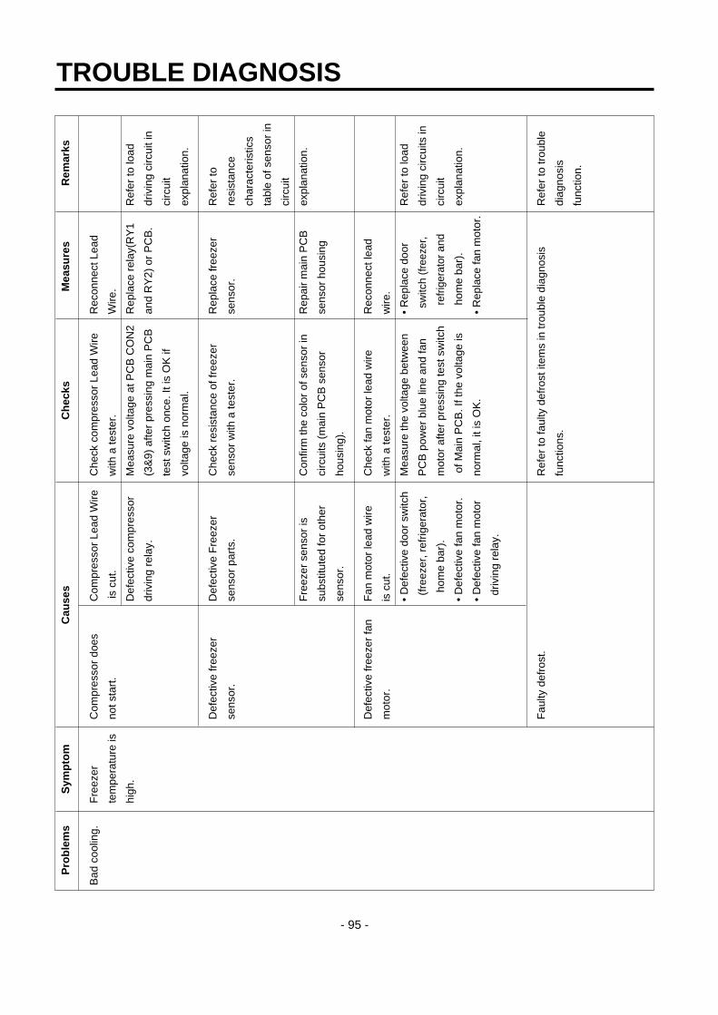
TROUBLE DIAGNOSIS
- 95 -
Pro
ble
ms
Sym
pto
mC
ause
sC
hec
ksM
easu
res
Rem
arks
Bad
coo
ling.
Fre
ezer
C
ompr
esso
r do
esC
ompr
esso
r Le
ad W
ireC
heck
com
pres
sor
Lead
Wire
R
econ
nect
Lea
d
tem
pera
ture
isno
t sta
rt.
is c
ut.
with
a te
ster
.W
ire.
high
.D
efec
tive
com
pres
sor
Mea
sure
vol
tage
at P
CB
CO
N2
Rep
lace
rel
ay(R
Y1
Ref
er to
load
driv
ing
rela
y.(3
&9)
afte
r pr
essi
ng m
ain
PC
Ban
d R
Y2)
or
PC
B.
driv
ing
circ
uit i
n
test
sw
itch
once
. It i
s O
K if
ci
rcui
t
volta
ge is
nor
mal
.ex
plan
atio
n.
Def
ectiv
e fr
eeze
r D
efec
tive
Fre
ezer
C
heck
res
ista
nce
of fr
eeze
r R
epla
ce fr
eeze
r R
efer
to
sens
or.
sens
or p
arts
.se
nsor
with
a te
ster
.se
nsor
.re
sist
ance
char
acte
ristic
s
tabl
e of
sen
sor
in
circ
uit
Fre
ezer
sen
sor
isC
onfir
m th
e co
lor
of s
enso
r in
R
epai
r m
ain
PC
Bex
plan
atio
n.
subs
titut
ed fo
r ot
her
circ
uits
(m
ain
PC
B s
enso
r se
nsor
hou
sing
sens
or.
hous
ing)
.
Def
ectiv
e fr
eeze
r fa
nF
an m
otor
lead
wire
C
heck
fan
mot
or le
ad w
ire
Rec
onne
ct le
ad
mot
or.
is c
ut.
with
a te
ster
.w
ire.
• D
efec
tive
door
sw
itch
Mea
sure
the
volta
ge b
etw
een
• R
epla
ce d
oor
Ref
er to
load
(fre
ezer
, ref
riger
ator
,P
CB
pow
er b
lue
line
and
fan
switc
h (f
reez
er,
driv
ing
circ
uits
in
hom
e ba
r).
mot
or a
fter
pres
sing
test
sw
itch
refr
iger
ator
and
ci
rcui
t
• D
efec
tive
fan
mot
or.
of M
ain
PC
B. I
f the
vol
tage
is
hom
e ba
r).
expl
anat
ion.
• D
efec
tive
fan
mot
orno
rmal
, it i
s O
K.
• R
epla
ce fa
n m
otor
.
driv
ing
rela
y.
Fau
lty d
efro
st.
Ref
er to
faul
ty d
efro
st it
ems
in tr
oubl
e di
agno
sis
Ref
er to
trou
ble
func
tions
.di
agno
sis
func
tion.

TROUBLE DIAGNOSIS
- 96 -
Pro
ble
ms
Sym
pto
mC
ause
sC
hec
ksM
easu
res
Rem
arks
Bad
coo
ling
Wro
ng
Def
ectiv
e S
tep
Mot
or
Che
ck S
tep
Mot
or
Che
ck if
Ste
p M
otor
dam
per
Rec
onne
ct le
ad
Ref
riger
ator
Dam
per.
dam
per
mot
or a
nd
mot
or a
nd r
eed
switc
h le
ad
wire
.
tem
pera
ture
.re
ed s
witc
h an
d le
ad
wire
are
cut
with
a te
ster
.
wire
are
cut
. Che
ck
Ref
er to
Ste
p M
otor
dam
per
Rep
lace
Ste
p M
otor
Ste
p M
otor
dam
per
in p
arts
rep
air
guid
e.da
mpe
ror r
efrig
erat
or
part
.co
ntro
l box
Ass
y.
Che
ck S
tep
Mot
or
Ref
er to
Ste
p M
otor
dam
per
Rep
lace
rel
ay o
r R
efer
to s
ingl
e
dam
per
Mot
or d
rivin
g in
par
ts r
epai
r gu
ide.
PC
B.
mot
or d
ampe
r
rela
y in
PC
B.
driv
ing
circ
uits
in c
ircui
t
expl
anat
ion.
For
eign
mat
eria
ls in
Ste
p C
heck
Ste
p M
otor
dam
per
Rem
ove
fore
ign
Mot
or d
ampe
r ba
ffles
.ba
ffle
visu
ally
.m
ater
ials
.
Ice
form
atio
n on
C
heck
if S
tep
Mot
or d
ampe
r R
epla
ce S
tep
Mot
or
Ste
p M
otor
dam
per
Hea
ter
wire
is c
ut w
ith a
da
mpe
r or
ref
riger
ator
baffl
es.
test
er.
cont
rol B
ox A
ssy.
Def
ectiv
e re
frig
erat
orD
efec
tive
refr
iger
ator
Che
ck th
e re
sist
ance
of
Rep
lace
ref
riger
ator
Ref
er to
sen
sor
sens
orse
nsor
par
ts.
refr
iger
ator
sen
sor
with
a te
ster
.se
nsor
.re
sist
ance
char
acte
ristic
tabl
e in
circ
uit
expl
anat
ion.
Ref
riger
ator
sen
sor
isC
heck
the
sens
or c
olor
in th
e R
epai
r m
ain
PC
B
subs
titut
ed fo
r ot
her
circ
uit.
(mai
n P
CB
sen
sor
sens
or h
ousi
ng.
sens
or.
hous
ing.
)
Def
ectiv
e re
frig
erat
orC
heck
if r
efrig
erat
or s
enso
rF
ix a
gain
the
sens
or a
ssem
bly
is n
ot fi
xed
at c
over
sen
sor
but
refr
iger
ator
sen
sor.
cond
ition
.in
ner
case
vis
ually
.
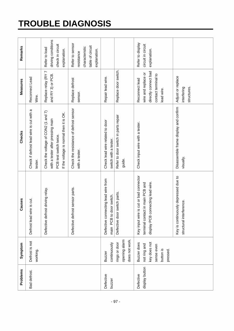
TROUBLE DIAGNOSIS
- 97 -
Pro
ble
ms
Sym
pto
mC
ause
sC
hec
ksM
easu
res
Rem
arks
Bad
def
rost
.D
efro
st is
not
Def
rost
lead
wire
is c
ut.
Che
ck if
def
rost
lead
wire
is c
ut w
ith a
R
econ
nect
Lea
d
wor
king
.te
ster
.W
ire.
Def
ectiv
e de
fros
t driv
ing
rela
y.C
heck
the
volta
ge o
f CO
N2
(1 a
nd 7
) R
epla
ce r
elay
(R
Y 7
Ref
er to
load
with
a te
ster
afte
r pr
essi
ng m
ain
and
RY
3)
or P
CB
.dr
ivin
g co
nditi
ons
PC
B te
st s
witc
h tw
ice.
ch
eck
in c
ircui
t
If th
e vo
ltage
is n
orm
al th
en it
is O
K.
expl
anat
ion.
Def
ectiv
e de
fros
t sen
sor
part
s.C
heck
the
resi
stan
ce o
f def
rost
sen
sor
Rep
lace
def
rost
R
efer
to s
enso
r
with
a te
ster
.se
nsor
.re
sist
ance
char
acte
ristic
tabl
e of
circ
uit
expl
anat
ion.
Def
ectiv
e B
uzze
r D
efec
tive
conn
ectin
g le
ad w
ire fr
om
Che
ck le
ad w
ire r
elat
ed to
doo
r R
epai
r le
ad w
ire.
buzz
erco
ntin
uous
lym
ain
PC
B to
doo
r sw
itch.
switc
h w
ith a
test
er.
rings
or
door
Def
ectiv
e do
or s
witc
h pa
rts.
Ref
er to
doo
r sw
itch
in p
arts
rep
air
Rep
lace
doo
r sw
itch.
open
ing
alar
m
guid
e.
does
not
wor
k.
Def
ectiv
e B
uzze
r do
es
Key
inpu
t wire
is c
ut o
r ba
d co
nnec
tor
Che
ck in
put w
ire w
ith a
test
er.
Rec
onne
ct le
ad
Ref
er to
dis
play
disp
lay
butto
nno
t rin
g an
d te
rmin
al c
onta
ct in
mai
n P
CB
and
w
ire a
nd r
epla
ce o
r ci
rcui
t in
circ
uit
key
does
not
disp
lay
PC
B c
onne
ctin
g le
ad w
ire.
dire
ctly
con
nect
bad
expl
anat
ion.
sens
e ev
en
cont
act t
erm
inal
to
butto
n is
le
ad w
ire.
pres
sed.
Key
is c
ontin
uous
ly d
epre
ssed
due
to
Dis
asse
mbl
e fr
ame
disp
lay
and
conf
irm
Adj
ust o
r re
plac
e
stru
ctur
al in
terf
eren
ce.
visu
ally
.in
terf
erin
g
stru
ctur
es.

TROUBLE DIAGNOSIS
- 98 -
Pro
ble
ms
Sym
pto
mC
ause
sC
hec
ksM
easu
res
Rem
arks
Def
ectiv
eB
uzze
r rin
gs
Tro
uble
mod
e in
dica
tion.
Che
ck tr
oubl
e di
agno
sis
func
tion.
Rep
air
trou
bles
Ref
er to
mod
e
disp
lay
butto
n.bu
t key
doe
sin
dica
tion
in
not s
ense
eve
nfu
nctio
n
butto
n is
ex
plan
atio
ns.
pres
sed.
Doo
r B
uzze
rB
uzze
r D
efec
tive
conn
ectin
g le
ad w
ire fr
om
Che
ck le
ad w
ire a
ssoc
iate
d w
ith d
oor
Rep
air
lead
wire
.C
heck
mod
el
cont
inuo
usly
mai
n P
CB
to d
oor
switc
h.sw
itch.
with
dis
pens
er.
rings
or
door
Def
ectiv
e fr
eeze
r co
mpa
rtm
ent d
oor
Ref
er to
doo
r sw
itch
in p
arts
rep
air
Rep
lace
Fre
ezer
open
ing
alar
msw
itch
part
s.gu
ide.
com
part
men
t doo
r
does
not
wor
k.sw
itch.
Bad
wat
er/ic
eIc
e an
d w
ater
Def
ectiv
e co
nnec
ting
lead
wire
from
C
heck
Lea
d W
ire a
ssoc
iate
d w
ith le
ver
Rep
air
lead
wire
.
disp
ense
r.ar
e no
tM
ain
PC
B to
leve
r sw
itch.
switc
h w
ith a
test
er.
disp
ense
d.D
efec
tive
leve
r sw
itch
part
sR
efer
to d
oor
switc
h in
par
ts r
epai
r gu
ide.
Rep
lace
leve
r sw
itch.
Def
ectiv
e ph
oto
coup
ler
IC p
arts
.C
heck
vol
tage
cha
nge
at p
hoto
cou
pler
Rep
lace
pho
to
outp
ut te
rmin
als
with
leve
r sw
itch
coup
ler
IC o
r P
CB
.
pres
sed.
It is
OK
if v
olta
ge c
hang
e is
betw
een
0V
- 5
V.
Def
ectiv
e re
lay
asso
ciat
ed w
ith ic
e C
heck
rel
ay (
RY
4, R
Y5,
RY
12)
Rep
lace
def
ectiv
e
disp
ense
(ge
ared
mot
or, c
ube
and
with
a te
ster
.re
lay.
disp
ense
r so
leno
id).
Def
ectiv
e pa
rts
asso
ciat
ed w
ith ic
e C
heck
res
ista
nce
of p
arts
with
a te
ster
.R
epla
ce d
efec
tive
disp
ense
(ge
ared
mot
or, c
ube
and
part
s.
disp
ense
r so
leno
id).
Def
ectiv
e re
lay
asso
ciat
ed w
ith w
ater
Che
ck r
elay
(R
Y7)
with
a te
ster
Rep
lace
def
ectiv
e
disp
ense
.re
lay.
Def
ectiv
e pa
rts
asso
ciat
ed w
ith w
ater
Che
ck r
esis
tanc
e of
par
ts w
ith a
test
er.
Rep
lace
def
ectiv
e
disp
ense
r.pa
rts.

3. Cooling Cycle Heavy Repair
3-1. The Heavy Repair Standards for Refrigerator with R134a Refrigerant
NOTE) Please contact Songso company on +82-53-554-2067 if you have inquiry on heavy repair special facility.
TROUBLE DIAGNOSIS
- 99 -
NO. Items Unit Standards Purposes Remarks1 Pipe and piping Min. Pipe:within 1 hour. To protect The opening time should be reduced to a
system opening time. Comp:within Moisture half of the standards during rain and 10 minutes. Penetration. rainy seasons (the penetration of water
Drier:within into the pipe is dangerous).20 minutes.
2 Welding. Nitrogen Weld under To protect - Refet to repair note in each part.Pressure. Nitrogen oxide scale - R134a refrigerant is more susceptible to
atmosphere formation. leaks than R12 and requires more care(N2 pressure: during welding.0.1~0.2 kg/cm2) - Do not apply force to pipes before and
after welding to protect pipe from cracking.
3 N2 sealed parts. Confirm N2 Confirm air leaking To protect - In case of evaporator parts, if it doesn't leak. sounds when moisture noise when removing rubber cap blow
removing rubber penetration. dry air or N2 gas for more than 1 min cap. use the parts.Sound:usableNo sound:not usable
4 Refrigeration Evacuation Min. More than To removeCycle. time 40 minutes. moisture.
Vacuum Torr Below 0.03(ref) Note:Only applicable to the model degree equipped with reverse flow protect
plate.Vacuum EA High and low Vaccum efficiency can be improved by
Pressure sides are operating compressor during evacuation.evacuated at thesame time formodels above 200L
Vacuum EA Use R134a To protect The rubber pipes for R12 refrigerant shall piping exclusive mixing of be melted when they are used for R134a
manifold. mineral and refrigerant(causes of leak).ester oils.
Pipe EA Use R134a To protectcoupler cxclusive. R12 Refri-
gerant mixing.Outlet R134a exclusive. ˝
(Socket)Plug R134a exclusive ˝
5 Refrigerant weighing. EA Use R134a Do not mix - Do not weight the refrigerant at too hot or exclusively. with R12 too cold an area.(25°C is adequate.)Weighing refrigerant. - Use copper bombe allowance:±5g Socket:2SV Plug: 2PV R134aNote:Winter:-5g Note:Do not burn O-ring (rubber) during
Summer:+5g welding.6 Drier replacement. -Use R134a exclusively To remove
for R134a refrigerator the moisture-Use R12 exclusively from pipe.for R12 refrigerator-Replace drier wheneverrepairing refrigeratorcycle piping.
7 Leak check. -Do not use soapy Detect -Check oil leak at refrigerant leak area. water for check. refrigerant Use electronic leak detector if oil leak is it may be sucked leak area. not found.into the pipe by. -The electronic leak detector is very
sensitive to halogen gas in the air. It also can detect R141b in urethane. Please practice, therfore, many times before use.

3-2. Summary Of Heavy Repair
TROUBLE DIAGNOSIS
- 100 -
Process Contents Tools
- Cut charging pipe ends and discharge refrigerant from Filter, side cutters
drier and compressor.
- Use R134a oil and refrigerant for compressor and drier Pipe Cutter, Gas welder, N2 gas
- Confirm N2 sealing and packing conditions before use.
Use good one for welding and assembly.
- Weld under nitrogen gas atmosphere.(N2 gas pressure:
0.1-0.2kg/cm2).
- Repair in a clean and dry place.
- Evacuate for more than forty minutes after connecting Vacuum pump(R134a
manifold gauge hose and vacuum pump to high (drier) exclusively), Manifold gauge.
and low (compressor refrigerant discharging parts)
pressure sides.
- Evacuation Speed:113l/min.
- Weigh and control the allowance of R134a bombe in a R134a exclusive bombe(mass
vacuum conditions to be ±5 g with electronic scales and cylinder), refrigerant(R134a)
charge through compressor inlet manifold gauge, electronic
(Charge while refrigerator operates). scales, punching off flier,
- Weld carefully after inlet pinching. gas welding machine
- Check leak at weld joints. Electronic Leak Detector,
Minute leak: Use electronic leak detector Driver(Ruler).
Big leak: Check visually or fingers.
Note:Do not use soapy water for check.
- Check cooling capacity
➀ Check radiator manually to see if warm.
➁ Check hot line pipe manually to see if warm.
➂ Check frost formation on the whole surface of the
evaporator.
- Remove flux from the silver weld joints with soft brush Copper brush, Rag, Tool box
or wet rag.(Flux may be the cause of corrosion and
leaks.)
- Clean R134a exclusive tools and store them in a clean
tool box or in their place.
- Installation should be conducted in accordance with the
standard installation procedure.(Leave space of more
than 5 cm from the wall for compressor compartment
cooling fan mounted model.)
Troublediagnosis
Remove refrigerantResiduals
Partsreplacementand welding
Compressorcompartment
and toolsarrangement
Transportationand
installation
Checkrefrigerant leak
and coolingcapacity
Vacuum
Refrigerantcharging and
charginginlet welding

3-3. Precautions During Heavy Repair
TROUBLE DIAGNOSIS
- 101 -
Items Precautions
1. Use of tools. 1) Use special parts and tools for R134a.
2. Removal of retained 1) Remove retained refrigerant more than 5 minutes after turning off a refrigerator.
refrigerant. (If not, oil will leak inside.)
2) Remove retained refrigerant by cutting first high pressure side (drier part) with a nipper and
then cut low pressure side. (If the order is not observed, oil leak will happen.)
3. Replacement of drier. 1) Be sure to replace drier with R134a only when repairing pipes and injecting refrigerant.
4. Nitrogen blowing 1) Weld under nitrogen atmosphere in order to prevent oxidation inside a pipe.
welding. (Nitrogen pressure : 0.1~0.2 kg/cm2.)
5. Others. 1) Nitrogen or refrigerant R134a only should be used when cleaning inside of cycle pipes
inside and sealing.
2) Check leakage with an electronic leakage tester.
3) Be sure to use a pipe cutter when cutting pipes.
4) Be careful not the water let intrude into the inside of the cycle.
1
2
Compressor
Low pressure side CondenserHigh pressure side
Drier
Evaporator
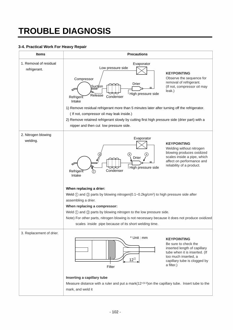
3-4. Practical Work For Heavy Repair
TROUBLE DIAGNOSIS
- 102 -
Items Precautions
1. Removal of residual
refrigerant.
1) Remove residual refrigerant more than 5 minutes later after turning off the refrigerator.
( If not, compressor oil may leak inside.)
2) Remove retained refrigerant slowly by cutting first high pressure side (drier part) with a
nipper and then cut low pressure side.
2. Nitrogen blowing
welding.
When replacing a drier:
Weld a and b parts by blowing nitrogen(0.1~0.2kg/cm2) to high pressure side after
assembling a drier.
When replacing a compressor:
Weld a and b parts by blowing nitrogen to the low pressure side.
Note) For other parts, nitrogen blowing is not necessary because it does not produce oxidized
scales inside pipe because of its short welding time.
3. Replacement of drier.
Inserting a capillary tube
Measure distance with a ruler and put a mark(12+3/-0)on the capillary tube. Insert tube to the
mark, and weld it
KEYPOINTINGObserve the sequence forremoval of refrigerant.(If not, compressor oil mayleak.)
KEYPOINTINGWelding without nitrogenblowing produces oxidizedscales inside a pipe, whichaffect on performance andreliability of a product.
KEYPOINTINGBe sure to check theinserted length of capillarytube when it is inserted. (Iftoo much inserted, acapillary tube is clogged bya filter.)
Compressor
Low pressure side
CondenserHigh pressure side
Drier
Evaporator
ReleaseRefrigentIntake
Suction
1 2 1
2
Evaporator
Drier
High pressure sideCondenserRefrigent
Intake
12+3-0
Filter
* Unit : mm
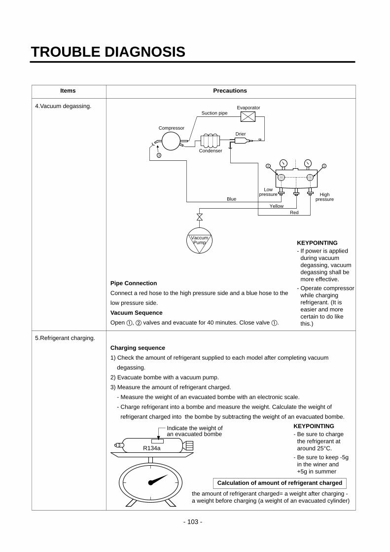
TROUBLE DIAGNOSIS
- 103 -
Items Precautions
4.Vacuum degassing.
Pipe Connection
Connect a red hose to the high pressure side and a blue hose to the
low pressure side.
Vacuum Sequence
Open a, b valves and evacuate for 40 minutes. Close valve a.
5.Refrigerant charging.
Charging sequence
1) Check the amount of refrigerant supplied to each model after completing vacuum
degassing.
2) Evacuate bombe with a vacuum pump.
3) Measure the amount of refrigerant charged.
- Measure the weight of an evacuated bombe with an electronic scale.
- Charge refrigerant into a bombe and measure the weight. Calculate the weight of
refrigerant charged into the bombe by subtracting the weight of an evacuated bombe.
KEYPOINTING- If power is applied
during vacuumdegassing, vacuumdegassing shall bemore effective.
- Operate compressorwhile chargingrefrigerant. (It iseasier and morecertain to do likethis.)
KEYPOINTING- Be sure to charge
the refrigerant ataround 25°C.
- Be sure to keep -5gin the winer and+5g in summer
the amount of refrigerant charged= a weight after charging -a weight before charging (a weight of an evacuated cylinder)
Calculation of amount of refrigerant charged
2 1
3
Compressor
Lowpressure
Condenser
Highpressure
Drier
Evaporator
RedYellow
Blue
VaccumPump
Suction pipe
R134a
Indicate the weight ofan evacuated bombe

3-5. Standard Regulations For Heavy Repair
TROUBLE DIAGNOSIS
- 104 -
Items Precautions
4) Refrigerant Charging
Charge refrigerant while operating a compressor as shown above.
5) Pinch a charging pipe with a pinch-off plier after completion of charging.
6) Braze the end of a pinched charging pipe with copper brazer and take a gas leakage test
on the welded parts.
6. Gas-leakage test * Take a leakage test on the welded or suspicious area with an electronic leakage tester.
7. Pipe arrangement Check each pipe is placed in its original
in each cycle place before closing a cover back-M/C
after completion of work. Particularly
control the size of Joint Drain Pipe
Compressor
Condenser
Drier
Evaporator
Bombe
Rubber
1) Observe the safety precautions for gas handling.
2) Use JIG (or wet towel) in order to prevent electric wires from burning during welding. (In order to prevent insulationbreak and accident.)
3) The inner case shall be melted and insulation material (polyurethane) shall be burnt if not cared during welding innercase parts.
4) The copper pipe shall be oxidized by overheating if not cared during welding.
5) Not allow the aluminum pipes to contact to copper pipes. (In order to prevent corrosion.)
6) Observe that the inserted length of a capillary tube into a drier should be 12 mm.
7) Make sure that the inner diameter should not be distorted while cutting a capillary tube.
8) Be sure that a suction pipe and a filling tube should not be substituted each other during welding. ( High efficiencypump.)
12 mm+3-0
DrierMolecular PipeMolecular
Sieves
+3-0
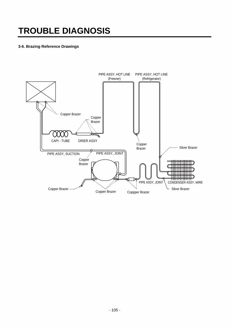
3-6. Brazing Reference Drawings
TROUBLE DIAGNOSIS
- 105 -
PIPE ASSY, JOINT
PIPE ASSY, HOT LINE(Freezer)
PIPE ASSY, HOT LINE(Refrigerator)
PIPE ASSY, JOINT CONDENSER ASSY, WIRE
PIPE ASSY, SUCTION
DRIER ASSYCAPI - TUBE
Copper BrazerCopperBrazer
Silver Brazer
CopperBrazer
Copper BrazerCopper Brazer Coppper Brazer
Silver Brazer
CopperBrazer

4. HOW TO DEAL WITH CLAIMS
4-1. Sound
TROUBLE DIAGNOSIS
- 106 -
Problems Checks and Measures
"Whizz" sounds Explain general principles of sounds.• All refrigerator when functioning properly have normal operating sound. The
compressor and fan produce sounds.There is a fan in the freezer compartment which blows cool air to freezer andrefrigerator compartments. "Whizz" sounds are heard when the air passesthrough the narrow holes into the freezer and refrigerator compartments.
Cooling Fan sound in the compressor compartment.• There is a fan on the back of the refrigerator, which cools the compressor
compartment. If there is a small space between the refrigerator and the wall, theair circulation sounds may be noticeable.
Noise of Compressor.• This operating sound happens when the compressor compresses the
refrigerant. The compressor rotates at 3600RPM. The sound of compressoroperation becomes louder as the refrigerator capacity increases.
"Click" sounds Explain the principles of temperature change.• The sounds happens when pipes and internal evaporator in the refrigerator
compartment expand and contract as the temperature changes during therefrigerator operation. This sound also happens during defrosting, twice a day,when the ice on the evaporator melts.
"Clunk" sound Explain that it comes from the compressor when the refrigerator starts.• When the refrigerator operates, the piston and motor in the compressor rotate
at 3600RPM. This sound is caused by the vibration of motor and piston whenthey start and finish their operation. This phenomena can be compared with thatof cars. When the car engine ignites and starts to rotate, the loud soundbecomes gradually quiet. When the engine stops, it stops with vibration.
Vibration sound Check the sound whether it comes from the pipes vibration and friction.• Insert rubber or leave a space between pipes to avoid the noise.• Fix the fan blade if the noise is due to the collision of fan and shroud.• Fix the drip tray if it is loosened.
Sound depends on the installation location.• Sound becomes louder if the refrigerator is installed on a wooden floor or near a
wooden wall. Move it to the another location.• If the refrigerator is not leveled properly, a small vibration can make a loud
sound. Please adjust the level of the refrigerator.
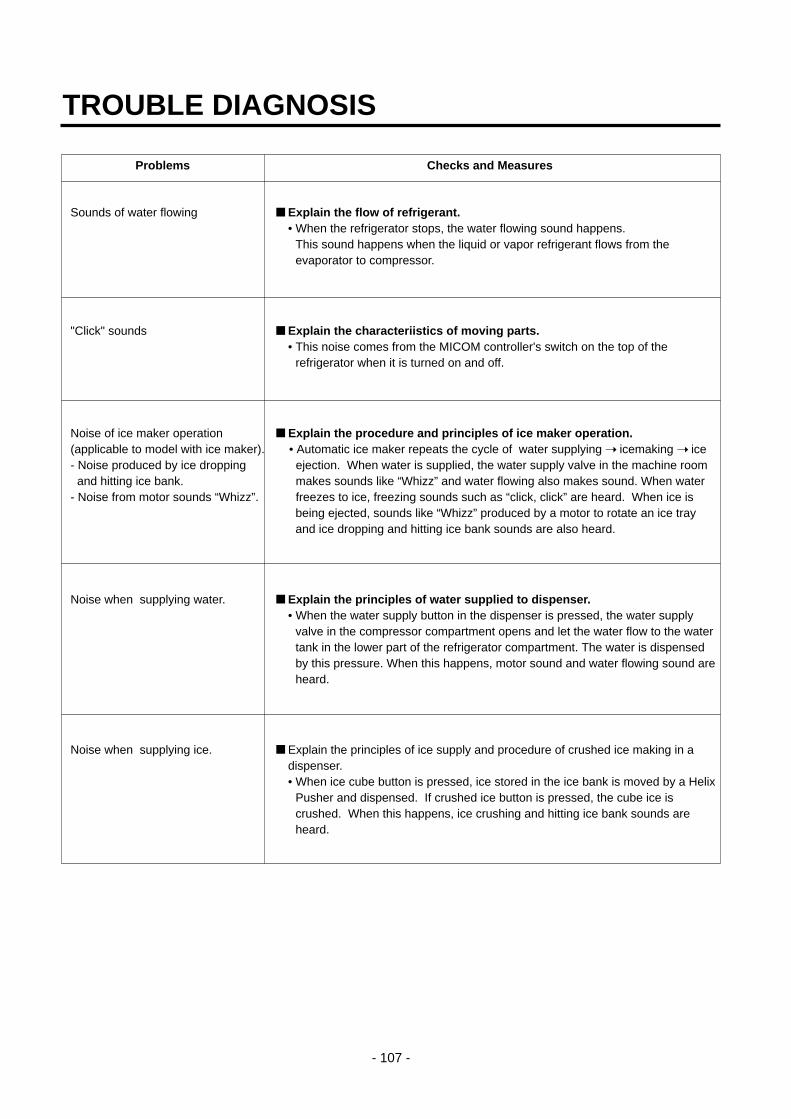
TROUBLE DIAGNOSIS
- 107 -
Problems Checks and Measures
Sounds of water flowing Explain the flow of refrigerant.• When the refrigerator stops, the water flowing sound happens.
This sound happens when the liquid or vapor refrigerant flows from theevaporator to compressor.
"Click" sounds Explain the characteriistics of moving parts.• This noise comes from the MICOM controller's switch on the top of the
refrigerator when it is turned on and off.
Noise of ice maker operation Explain the procedure and principles of ice maker operation.(applicable to model with ice maker). • Automatic ice maker repeats the cycle of water supplying icemaking ice - Noise produced by ice dropping ejection. When water is supplied, the water supply valve in the machine room and hitting ice bank. makes sounds like “Whizz” and water flowing also makes sound. When water
- Noise from motor sounds “Whizz”. freezes to ice, freezing sounds such as “click, click” are heard. When ice isbeing ejected, sounds like “Whizz” produced by a motor to rotate an ice trayand ice dropping and hitting ice bank sounds are also heard.
Noise when supplying water. Explain the principles of water supplied to dispenser.• When the water supply button in the dispenser is pressed, the water supply
valve in the compressor compartment opens and let the water flow to the watertank in the lower part of the refrigerator compartment. The water is dispensedby this pressure. When this happens, motor sound and water flowing sound areheard.
Noise when supplying ice. Explain the principles of ice supply and procedure of crushed ice making in adispenser.• When ice cube button is pressed, ice stored in the ice bank is moved by a Helix
Pusher and dispensed. If crushed ice button is pressed, the cube ice iscrushed. When this happens, ice crushing and hitting ice bank sounds areheard.

4-2. Measures for Symptoms on Temperature
TROUBLE DIAGNOSIS
- 108 -
Problems Checks and Measures
Refrigeration is weak. Check temperature set in the temperature control knob.• Refrigerator is generally delivered with the button set at “normal use” (MID).
But customer can adjust the temperature set depending on their habit and taste.If you feel the refrigeration is weak, then set the temperature control button at“strong” position. If you adjust the button in the freezer compartment as well, the refrigeration is stronger than adjusting refrigerator only.
The food in the chilled drawer is . The chilled drawer does not freeze food.not frozen but defrosted • Use chilled drawer for storing fresh meat or fish for short periods. For storing for
a long periods or freezing food, use a freezer compartment. It is normal thatfrozen foods thaw above the freezing temperature (in the chilled drawer).
Refrigerator water is not cool. Check the water storage location.• If water is kept in the door rack, please ask to keep it in the refrigerator
compartment shelf. It will then become cooler.
Ice cream softens. Explain the characteristics of ice cream.• The freezing point of ice cream is below -15°C. Therefore ice cream may melt if
it is stored in the door rack.• Store ice cream in a cold place or set the temperature control button of a freezer
at “strong” position.
Refrigeration is too strong. Check the position of temperature control button.• Check if refrigeration is strong in whole area of the refrigerator or partly near the
outlet of the cooling air. If it is strong in whole area, set the control button at“weak”. If it is strong only near the outlet of cool air, keep food (particularly wetand easy to frozen such as bean curd and vegetables) away from the outlet.
Vegetables are frozen. Check the vegetables storage.• If vegetables are stored in the refrigerator shelf or chilled drawer instead of
vegetable drawer, they will be frozen. Set the control button at “weak” if they arealso frozen in the vegetable drawer.
The food stored at inside of Check if food is stored near the outlet of the cooling air. the shelf freezes even the • The temperature at cooling air outlet is always below the freezing point. control button is set at “MID”. Do not store food near the outlet of the cooling air as it block the air circulation.
And do not block the outlet. If the outlet of the cooling air is blocked, therefrigerator compartment will not be cooled.
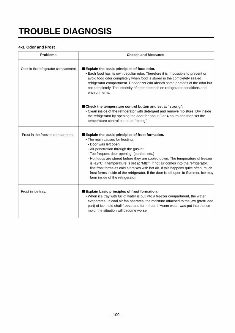
4-3. Odor and Frost
TROUBLE DIAGNOSIS
- 109 -
Problems Checks and Measures
Odor in the refrigerator compartment. Explain the basic principles of food odor.• Each food has its own peculiar odor. Therefore it is impossible to prevent or
avoid food odor completely when food is stored in the completely sealedrefrigerator compartment. Deodorizer can absorb some portions of the odor butnot completely. The intensity of odor depends on refrigerator conditions andenvironments.
Check the temperature control button and set at “strong”.• Clean inside of the refrigerator with detergent and remove moisture. Dry inside
the refrigerator by opening the door for about 3 or 4 hours and then set thetemperature control button at “strong”.
Frost in the freezer compartment Explain the basic principles of frost formation.• The main causes for frosting:
- Door was left open.- Air penetration through the gasket- Too frequent door opening. (parties. etc.)- Hot foods are stored before they are cooled down. The temperature of freezer
is -19°C. if temperature is set at “MID”. If hot air comes into the refrigerator,fine frost forms as cold air mixes with hot air. If this happens quite often, muchfrost forms inside of the refrigerator. If the door is left open in Summer, ice mayform inside of the refrigerator.
Frost in ice tray. Explain basic principles of frost formation.• When ice tray with full of water is put into a freezer compartment, the water
evaporates. If cool air fan operates, the moisture attached to the jaw (protrudedpart) of ice mold shall freeze and form frost. If warm water was put into the icemold, the situation will become worse.

4-5. Others
TROUBLE DIAGNOSIS
- 110 -
Problems Checks and Measures
The refrigerator case is hot. Explain the principles of radiator.• The radiator pipes are installed in the refrigerator case and partition plate
between the refrigerator and the freezer compartment in order to preventcondensation formation. Particularly in summer or after installation ofrefrigerator, it may feel hot but it is normal. If there is no enough space todissipate heat, it can be hotter due to lack of heat radiation. Please install arefrigerator in a well-ventilated place and leave a clearance between refrigeratorand wall:
Small holes in a door liner Explain that the hole is for releasing gas.• A small hole in the door liner is for releasing gas during insulation materials
lining work. With a releasing hole, forming can be easily done .
Electric bills are too much. Check the use conditions.• Too frequent door opening and hot food storing cause the compressor to
operate continuously and hence increase the electric consumption and bills.
Condensation on the inside Explain how to store foodswall of the refrigerator • Condensation forms when refrigerator is installed at damp area, door is compartment and the cover of frequently opened, and wet foods are not stored in the air tight container orproperly vegetable drawer. wrapped. Be sure to store wet foods in the air tight container or in the wrap.
When is the power connected? When should the power be connected ?• You can connect the power right after the installation. But if the refrigerator was
laid flat during transportation for a long period of time and the refrigerant andcompressor oils are mixed up, then this will affect badly the performance of arefrigerator. Be sure to connect the power 2~3 hours after refrigerator isinstalled.
Door does not open properly. Refrigerator compartment door does not open properly.• When the door is open, warm open air comes into the compartment and is mixed up with cool air. This mixed air shall be compressed and increase theinternal pressure when door is closed. This causes the door sticked closely tothe refrigerator in a moment. (If the refrigerator is used for a long time, it willthen open smoothly.)
When the refrigerator compartment door is open and close, the freezercompartment door moves up and down.• When the refrigerator compartment door is open and close, fresh air comes into
the freezer compartment and moves up and down the freezer compartmentdoor.
Door opens too easily.• There is a magnet in the gasket rubber so that it is ok. if door is securely closed
without a gap. It can be open easily if the foods in the refrigerator or freezercompartments hold the door open.
A door does not close properly. • If the rear side of the refrigerator is raised higher than front side, door shall not
be easily closed. Adjust the level of refrigerator with levelling screws.
The front side shouldbe raised a little bit higher
than the rear side.

1. DOOR
1) Remove lower cover and then disconnect watersupply tube in the lower part of freezer door.
• Pull a water supply tube b forward while pressing a partto disconnect water supply tube as shown below.
2) Remove a freezer door.(1) Loosen hinge cover screw of freezer door and remove
cover. Disconnect all connecting lines except earthing cord.
(2) Turn hinge lever in arrow A direction until it isloosened and take it out in arrow B direction.
Note : • When disconnecting refrigerator door, turn hingelever counterclockwise.
• If hinge lever or bracket hinge pin is deformedduring assembling freezer and refrigerator doors,fix two screws (Tap Tite Screw, M6: Hinge, L fixingscrew) in the hole of upper hinge.
(3) Disconnect upper hinge a from a hinge supporter bby grasping the front part of upper hinge and lifting up(Hinge Assy, U) in arrow direction A and pull forwardin arrow B direction. Be careful as the door may befallen down.
(4) Lift up the freezer door a in arrow direction anddisconnect the door from the lower hinge b. Don’t pulla door forward.
Note : • Lift up a freezer door until a water supply tube isfully taken out.
(5) Assembly is the reverse order of disassembly
HOW TO DISASSEMBLE AND ASSEMBLE
- 111 -
2
1 A A B
1
2
1
2
Cover, Hinge
2Connecting
Line
EarthingCord
Lever, Hinge
A
B

2. HANDLE 1) Put blade screwdriver into a groove on the side of a
Deco handle and lift up a little bit in arrow a directionand push up with hand in arrow b direction anddisconnect.
2) Put blade screwdriver into a groove on the side of aDECO handle and lift up in arrow direction c and pushdown with hand in arrow direction d and disconnect.
3) Push up a piece handle c in arrow direction with handand disconnect.
4) Turn screw in arrow direction with a cross driver anddisconnect.
3. SHROUD, GRILLE FAN1) Loosen two screws after disconnecting a cap screw of a
grille fan(U) with a balde screwdriver.
2) Disassembly of a grille fan(U) : Pull forward afteropening hook at part with a blade screwdriver.
3) Disconnect housing A of a grille fan (L) from the mainbody.
4) Disassembly of a grille fan (L) : Hold upper part of agrille fan(L) and pull forward carefully.
5) Loosen two screws.
6) Disassembly of shroud. F(U) : Disconnect housing of Bafter removing two rail guides with a blade screwdriver.
7) Disassembly of shroud. F(U) : Hold upper part and pullforward.
8) Check foam PU sticking conditions around a shroud,F(U) and F(L) during assembling. If damaged, torn orbadly sticked, assemble with a new one after sealingwell.
4. ICEMAKER ASSY
1. Dispenser Model1) How to disassemble:
(1) Remove ice bank from the freezer compartment.
(2) Loosen two screws on the upper part of icemakerbracket.
(3) Disconnect icemaker bracket so that it can slideforward.
(4) Disconnect icemaker housing and sensor housing.
(5) Disconnect icemaker horizontally by pressing brackethook part. ( Don’t disassemble further. The set valuemay be changed.)
2) How to assemble : The assembly is the reverse order ofthe above disassembly.
Note : When the ice tray is not horizontal after assembly,assembly must be wrong. Check and assembleagain.
HOW TO DISASSEMBLE AND ASSEMBLE
- 112 -
1
Handle, Deco
2
3
4
Handle, Piece
Screw
Bracket, Ice MakerHook
Ice Maker Unit
Lever
Tray, Ice
Sensor
Insulation
Cover, Sensor
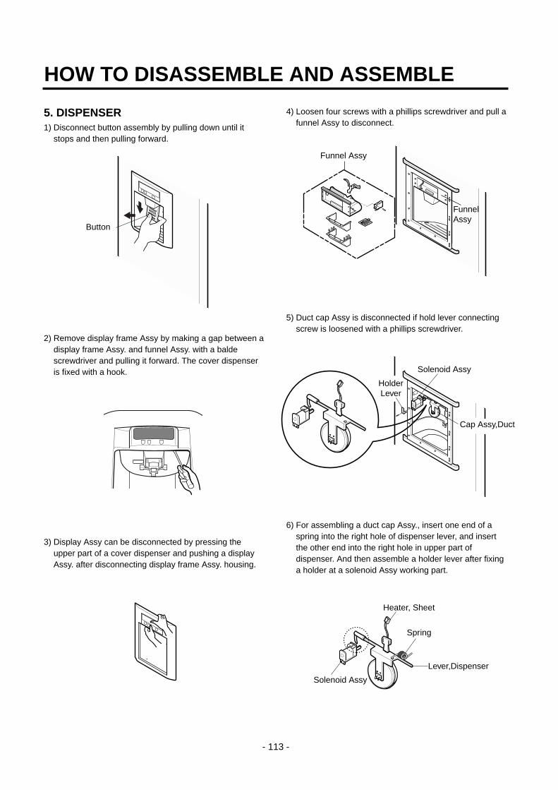
5. DISPENSER1) Disconnect button assembly by pulling down until it
stops and then pulling forward.
2) Remove display frame Assy by making a gap between adisplay frame Assy. and funnel Assy. with a baldescrewdriver and pulling it forward. The cover dispenseris fixed with a hook.
3) Display Assy can be disconnected by pressing theupper part of a cover dispenser and pushing a displayAssy. after disconnecting display frame Assy. housing.
4) Loosen four screws with a phillips screwdriver and pull afunnel Assy to disconnect.
5) Duct cap Assy is disconnected if hold lever connectingscrew is loosened with a phillips screwdriver.
6) For assembling a duct cap Assy., insert one end of aspring into the right hole of dispenser lever, and insertthe other end into the right hole in upper part ofdispenser. And then assemble a holder lever after fixinga holder at a solenoid Assy working part.
HOW TO DISASSEMBLE AND ASSEMBLE
- 113 -
Button
Funnel Assy
FunnelAssy
HolderLever
Solenoid Assy
Cap Assy,Duct
Spring
Heater, Sheet
Lever,Dispenser
Solenoid Assy

7) Dispenser Related Parts
HOW TO DISASSEMBLE AND ASSEMBLE
- 114 -
7
12
13
8
11
14
17 15
24
16
23
21
1
22
9
10
2
4
18 21
19
1 FRAME ASSY, DISPLAY
2 COVER, DISPENSER
4 PWB(PCB) ASSY, DISPLAY
7 FUNNEL ASSY
8 SWITCH, MICRO
9 FRAME, FUNNEL
10 LEVER(SWITCH)
11 FUNNEL
12 RUBBER, FUNNEL
13 SWITCH, ROCKER
14 SOLENOID ASSY
15 SPRING
16 HOLDER, LEVER
17 CAP, DUCT
19 LEVER, DISPENSER
20 RUBBER, CAP
21 BUTTON ASSY
22 BUTTON
23 HOLDER, BUTTON
24 DECO, DRAIN
< 17 Cap Assy, Duct Detailed Drawings>

6. WATER TANK AND WATER LINEu The water tank at back and lower part of a refrigerator is
fixed by one screw and has a capacity containing 7glasses (180cc per glass) of cold water. It will take timeto make more cold water in the tank.
* The first portion of dispensed water is not cold eventhough the refrigerator is working. In this case,dispense ice first in the cup and then water to make acold water.
7. HOME BAR
7-1. Home Bar related parts
7-2. Home Bar parts disassembly and assembly1) Disconnect H/Bar Door Assy a.
2) Loosen two screws g attached on the refrigeratorcompartment door with a phillips screwdriver. Andloosen 4 screws b and two screws c. Pull H/Bar doorAssy a. forward to disassemble.
3) Loosen two screws j, i fixed on H/Bar door Assy. andtwo screws k with a cross driver to disassemble armAssy.
4) Assemble parts by performing the disassembly inreverse order.
Note : • Assemble carefully parts g, j, k until they arefixed firmly when assembling them.
• Adjust exterior gap by adjusting parts b, g andwhen assembling.
HOW TO DISASSEMBLE AND ASSEMBLE
- 115 -
1
8
675
11
109
8
7
6
4
3
1110
9 2.0
5.0
1.8 1.8
1 DOOR ASSY, H/BAR 7 SCREW TAP TITE(ARM)
2 SEREW, TAP TITE(HINGE-H/B) 8 ARM ASSY
3 SCREW MACHINE(HINGE-H/B) 9 STOPPER
4 HINGE ASSY H/BAR 10 SCREW, MACHINE(STOP ARM-H/B)
5 HINGE ASSY H/BAR 11 SCREW MACHINE(HINGE-H/B)
6 CAP, ARM

Ref No. : GR-L247, GR-L207, GR-B247, GR-B207REFRIGERATOR DOOR PART
* : Optional part
EXPLODED VIEW
- 119 -
233A
232A
240C
240C
240A
240A
147A
231A
230A
234A
243A
243A
241B
241A
147B*147C*
236A*
206B*
206D*
206F*
205C*
205B*
205D*
205C*
205A*
205B
205A
205F

ICE & WATER PART
* : Optional part
EXPLODED VIEW
- 122 -
404B
614A
606A
610A
621B
612A
612B
612C
615A
616B
616C616A
613A
616E
623A*
623Aor
623B
618A
622A
616D*
404A
620A 620B
616A
611A
625A*
616G*
619A*
601A
605A
602A
607A
600A
603A
510B
603B
604A
616F*
627A*
617A
624B
619A*

MACHINE COMPARTMENT
* : Optional part
EXPLODED VIEW
- 123 -
300A310B
307A
304A
306A
310A
317B
317A
305C 305B
313A
301A
306C
306D
307A
104A
305C
305B
303C
303B
303D
303A
305A
407B
500A
502B
502A
411A
308A308C
308B
309B
403B
309B
309A
306C
105C
105D
105E
505A*
105F
407A*

DISPENSER PART
EXPLODED VIEW
- 124 -
278A
278E
278F
402C
278D
405A
275A 276A
275C401C
275D
275B
281A
276B
280C
280A
207A
277A
280B
278B
278C
279A
501A