Embed Size (px)
Citation preview
Ver. 100819
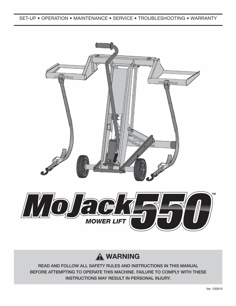
SET-UP • OPERATION • MAINTENANCE • SERVICE • TROUBLESHOOTING • WARRANTY
READ AND FOLLOW ALL SAFETY RULES AND INSTRUCTIONS IN THIS MANUALBEFORE ATTEMPTING TO OPERATE THIS MACHINE. FAILURE TO COMPLY WITH THESE
INSTRUCTIONS MAY RESULT IN PERSONAL INJURY.
WARNING
MOWER LIFT
2
INTRODUCTION
Patent #s: U.S., 8,448,920
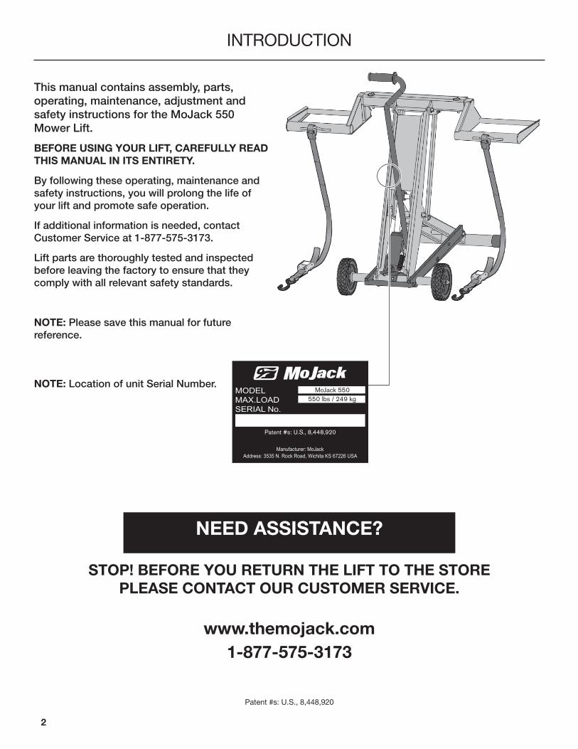
NOTE: Location of unit Serial Number.
NEED ASSISTANCE?
STOP! BEFORE YOU RETURN THE LIFT TO THE STORE PLEASE CONTACT OUR CUSTOMER SERVICE.
www.themojack.com
1-877-575-3173
This manual contains assembly, parts, operating, maintenance, adjustment and safety instructions for the MoJack 550 Mower Lift.
BEFORE USING YOUR LIFT, CAREFULLY READ THIS MANUAL IN ITS ENTIRETY.
By following these operating, maintenance and safety instructions, you will prolong the life of your lift and promote safe operation.
If additional information is needed, contact Customer Service at 1-877-575-3173.
Lift parts are thoroughly tested and inspected before leaving the factory to ensure that they comply with all relevant safety standards.
NOTE: Please save this manual for future reference.
3
WARNINGS AND SAFETY INSTRUCTIONS
IMPORTANT: The mower lift is intended for use with mowers only. Do not exceed 550 lbs. (249 kg) front end weight. It should never be used to service other types of machinery.
Spanish and French Canadian language manuals and decals are available upon request. Please contact 1-877-575-3173 to request an alternative language owners manual kit.
Manuels de compétence linguistique canadiens espagnols et français et des autocollants sont disponibles sur demande. S’il vous plaît contacter 1-877-575-3173 pour demander un kit manuel du propriétaire de l’autre langue.
Manuales de idiomas español y francés de Canadá y calcomanías están disponibles bajo petición. Por favor, póngase en contacto con 1-877-575-3173 para solicitar un kit propietarios manual de lenguaje alternativo.
Read and understand all safety and operating instructions before using the mower lift.
Never allow anyone unfamiliar with the safety or operating instructions to use the lift.
Follow all safety and servicing instructions provided by the lawn mower’s manufacturer before using the lift.
Do not modify the lift in any way. Any modifications will void any and all warranties and could compromise your personal safety.
When using the lift, keep ALL bystanders at a safe distance away from the mower lift.
The lift must be used on a solid level surface.
Only lift the FRONT end of the mower.
Do not lift the front end and back end of the mower at the same time.
Do not exceed the lifting capacity of 550 lbs. (249 kg) front end weight. If you have a question regarding weight of your machine, please contact Customer Service at 1-877-575-3173.
Only use the lift for mowers that properly fits in the provided wheel pads. (ie. 10” to 17” diameter and within the inside to outside wheel measurements of 18.5” to 47.5”).
Both Left and Right Wheel pads must be equal distance from the T-bar to maintain proper balance.
Always stop engine and remove key before beginning any work on the mower.
Always place wheel chocks (not included) behind the back tires of the mower before beginning maintenance. For additional safety, you may apply the parking brake after the wheel chocks are in place.
Never operate the engine while using the mower lift.
Do not remove safety warnings or decals from lift.
Please make sure that the space below the mower is big enough to work safely under the mower.
Please make sure that the mower is stable enough for work.
Failure to follow these warnings may result in property damage and serious bodily injury or death.

4
LIMITED WARRANTYFor two years for residential use and one year for commercial use MoJack warrants the product against failure due to defect in material or workmanship when product is used properly. MoJack will replace any defective part at no cost. This warranty does not cover any product that has been altered or adjusted, or any product that has been misused or abused. THIS IS THE CUSTOMER’S SOLE AND EXCLUSIVE REMEDY. MOJACK DISCLAIMS ALL IMPLIED WARRANTIES, INCLUDING THE WARRANTY OF MERCHANTABILITY AND FITNESS FOR A PARTICULAR PURPOSE. MOJACK SHALL NOT BE LIABLE FOR ANY INCIDENTAL OR CONSEQUENTIAL DAMAGES. SOME STATES OR PROVINCES DO NOT ALLOW THE EXCLUSION OR LIMITATION OF THE IMPLIED WARRANTIES OR THE REMEDIES FOR BREACH OF THE IMPLIED WARRANTIES, SO THESE EXCLUSIONS MAY NOT APPLY TO YOU. THIS LIMITED WARRANTY GIVES YOU SPECIFIC LEGAL RIGHTS, AND YOU MAY ALSO HAVE OTHER RIGHTS WHICH VARY FROM STATE TO STATE OR PROVINCE TO PROVINCE.
What does this warranty cover?This warranty covers against a failure due to a defect in material or workmanship within two years of purchase for residential use and within one year of purchase for commercial use.
What does this warranty NOT cover?This warranty does not cover any jack which has been altered or adjusted in any way from its original model. It will not cover any jack which has been damaged due to misuse, abuse, accident or negligence. This warranty does not cover incidental or consequential damages.
What is the period of coverage?Frame: 2 year for Residential. 1 year for CommercialHydraulic Cylinder: 1 year.
What will be done to correct problems?We will replace any defective part (within the coverage period) at no charge.
How can I get parts service?In order to be eligible for service under this warranty you MUST register your jack within thirty (30) days of purchasing. You must keep your receipt as proof of date of sale. You can register your new jack on our website at www.themojack.com or by calling our toll-free number 1-877-575-3173.
How do I contact someone about a warranty issue?You can contact our toll-free number 1-877-575-3173.
Do I have other rights under State Law?This warranty gives you specific legal rights, and you may also have other rights which vary from state to state.
What is the return policy?Please refer to the Return Policy and Procedures of your place of purchase for returns and refunds.
WARRANTY
5
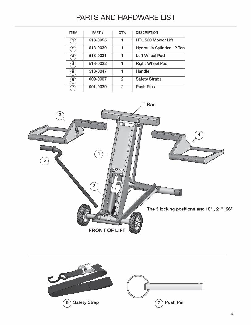
PARTS AND HARDWARE LIST
1
3
4
1
PART #
518-0055
518-0030
518-0031
518-0032
518-0047
009-0007
001-0039
DESCRIPTION
HTL 550 Mower Lift
Hydraulic Cylinder - 2 Ton
Left Wheel Pad
Right Wheel Pad
Handle
Safety Straps
Push Pins
QTY.
1
1
1
1
1
2
2
ITEM
2
7
3
4
5
7 Push Pin
5
2
6 Safety Strap
6
The 3 locking positions are: 18” , 21”, 26”
T-Bar
FRONT OF LIFT
6
ASSEMBLY AND OPERATING INSTRUCTIONSSTEP 1
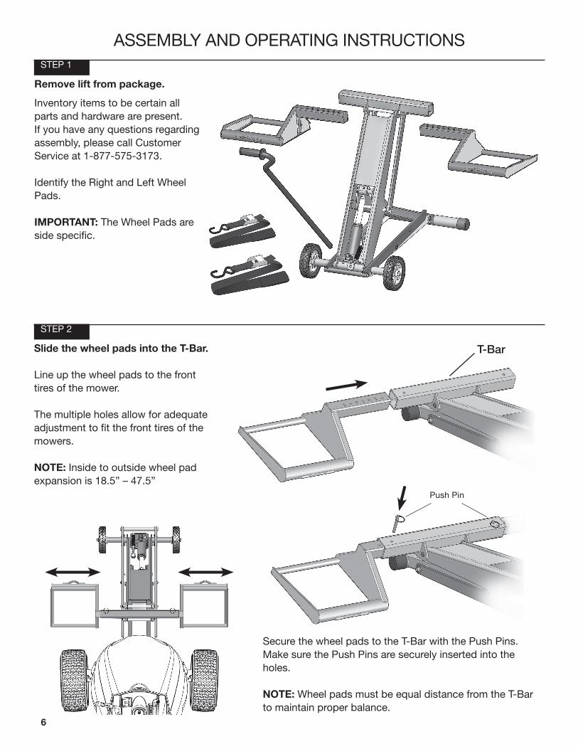
Remove lift from package.
Inventory items to be certain all parts and hardware are present. If you have any questions regarding assembly, please call Customer Service at 1-877-575-3173.
Identify the Right and Left Wheel Pads.
IMPORTANT: The Wheel Pads are side specific.
STEP 2
Slide the wheel pads into the T-Bar.
Line up the wheel pads to the front tires of the mower.
The multiple holes allow for adequate adjustment to fit the front tires of the mowers.
NOTE: Inside to outside wheel pad expansion is 18.5” – 47.5”
Secure the wheel pads to the T-Bar with the Push Pins. Make sure the Push Pins are securely inserted into the holes.
NOTE: Wheel pads must be equal distance from the T-Bar to maintain proper balance.
Push Pin
T-Bar
7
ASSEMBLY AND OPERATING INSTRUCTIONSSTEP 3
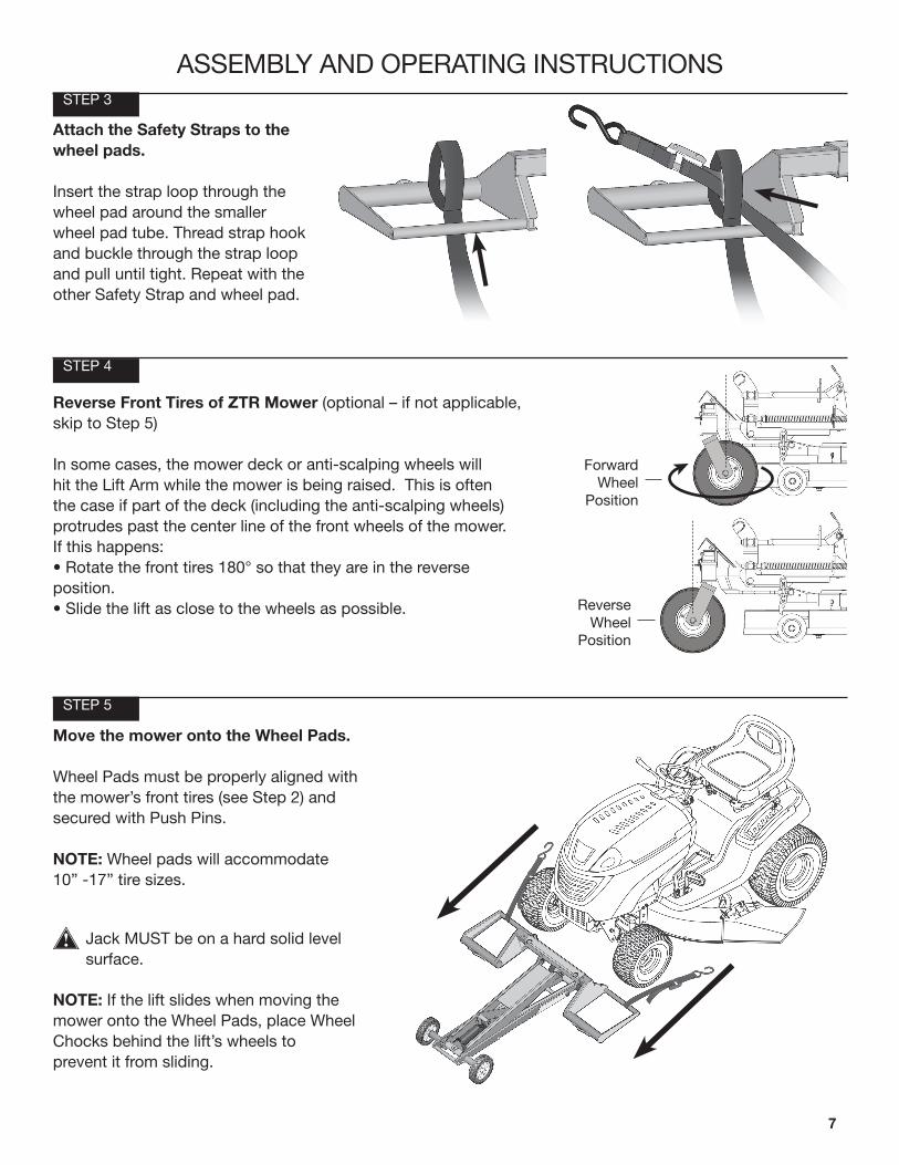
Attach the Safety Straps to the wheel pads.
Insert the strap loop through the wheel pad around the smaller wheel pad tube. Thread strap hook and buckle through the strap loop and pull until tight. Repeat with the other Safety Strap and wheel pad.
STEP 5
NOTE: If the lift slides when moving the mower onto the Wheel Pads, place Wheel Chocks behind the lift’s wheels toprevent it from sliding.
Jack MUST be on a hard solid level surface.
Move the mower onto the Wheel Pads.
Wheel Pads must be properly aligned with the mower’s front tires (see Step 2) and secured with Push Pins.
NOTE: Wheel pads will accommodate 10” -17” tire sizes.
STEP 4
Reverse Front Tires of ZTR Mower (optional – if not applicable, skip to Step 5)
In some cases, the mower deck or anti-scalping wheels will hit the Lift Arm while the mower is being raised. This is often the case if part of the deck (including the anti-scalping wheels) protrudes past the center line of the front wheels of the mower. If this happens: • Rotate the front tires 180° so that they are in the reverse position.• Slide the lift as close to the wheels as possible. Reverse
WheelPosition
ForwardWheel
Position
8
ASSEMBLY AND OPERATING INSTRUCTIONS
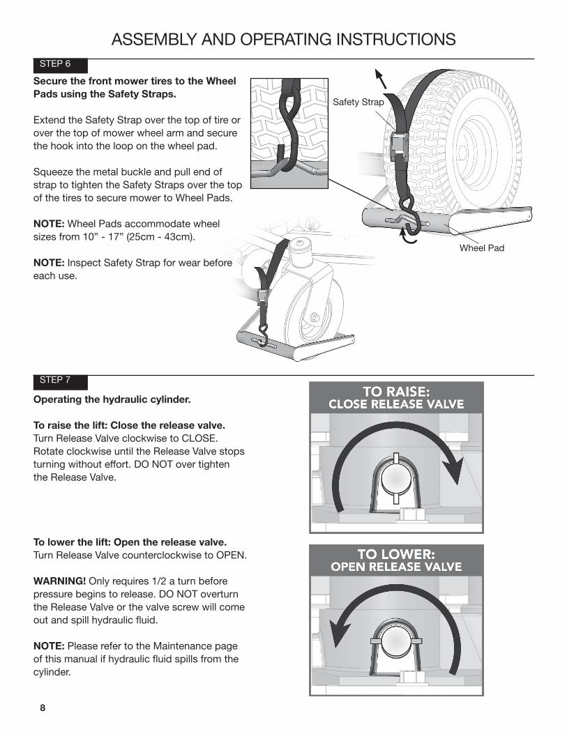
Operating the hydraulic cylinder.
To raise the lift: Close the release valve.Turn Release Valve clockwise to CLOSE.Rotate clockwise until the Release Valve stopsturning without effort. DO NOT over tightenthe Release Valve.
To lower the lift: Open the release valve.Turn Release Valve counterclockwise to OPEN.
WARNING! Only requires 1/2 a turn before pressure begins to release. DO NOT overturn the Release Valve or the valve screw will comeout and spill hydraulic fluid.
NOTE: Please refer to the Maintenance page of this manual if hydraulic fluid spills from the cylinder.
Safety Strap
Wheel Pad
STEP 7
STEP 6
Secure the front mower tires to the Wheel Pads using the Safety Straps.
Extend the Safety Strap over the top of tire or over the top of mower wheel arm and secure the hook into the loop on the wheel pad.
Squeeze the metal buckle and pull end of strap to tighten the Safety Straps over the top of the tires to secure mower to Wheel Pads.
NOTE: Wheel Pads accommodate wheel sizes from 10” - 17” (25cm - 43cm).
NOTE: Inspect Safety Strap for wear before each use.
9
ASSEMBLY AND OPERATING INSTRUCTIONSSTEP 8
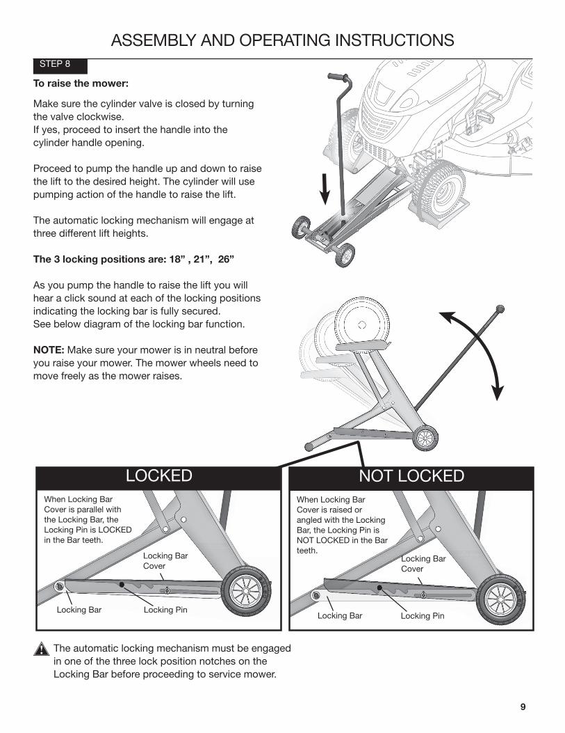
The automatic locking mechanism must be engaged in one of the three lock position notches on the Locking Bar before proceeding to service mower.
To raise the mower:
Make sure the cylinder valve is closed by turning the valve clockwise. If yes, proceed to insert the handle into the cylinder handle opening.
Proceed to pump the handle up and down to raise the lift to the desired height. The cylinder will use pumping action of the handle to raise the lift.
The automatic locking mechanism will engage at three different lift heights.
The 3 locking positions are: 18” , 21”, 26”
As you pump the handle to raise the lift you will hear a click sound at each of the locking positions indicating the locking bar is fully secured. See below diagram of the locking bar function.
NOTE: Make sure your mower is in neutral before you raise your mower. The mower wheels need to move freely as the mower raises.
LOCKEDWhen Locking Bar Cover is parallel with the Locking Bar, the Locking Pin is LOCKED in the Bar teeth.
Locking Pin
Locking Bar Cover
Locking Bar
NOT LOCKEDWhen Locking Bar Cover is raised or angled with the Locking Bar, the Locking Pin is NOT LOCKED in the Bar teeth.
Locking Pin
Locking Bar Cover
Locking Bar
10
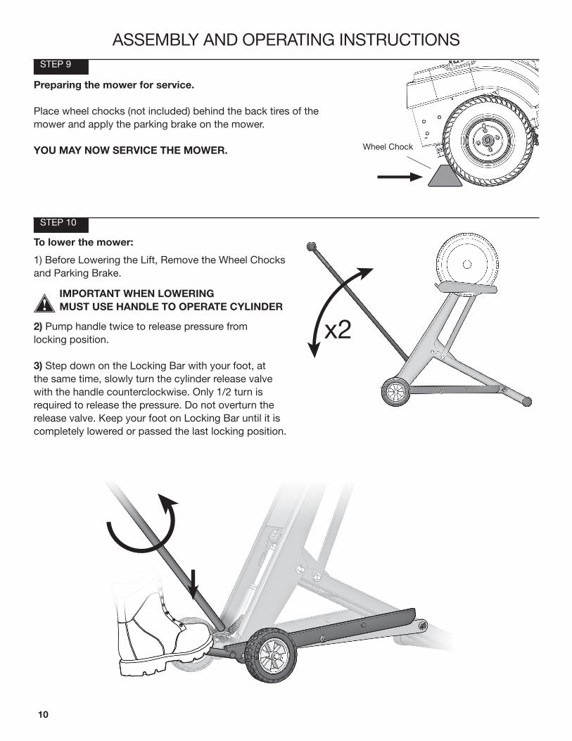
Preparing the mower for service.
Place wheel chocks (not included) behind the back tires of the mower and apply the parking brake on the mower.
YOU MAY NOW SERVICE THE MOWER. Wheel Chock
STEP 10
ASSEMBLY AND OPERATING INSTRUCTIONSSTEP 9
x2
To lower the mower:
1) Before Lowering the Lift, Remove the Wheel Chocks and Parking Brake.
IMPORTANT WHEN LOWERING MUST USE HANDLE TO OPERATE CYLINDER
2) Pump handle twice to release pressure from locking position.
3) Step down on the Locking Bar with your foot, at the same time, slowly turn the cylinder release valve with the handle counterclockwise. Only 1/2 turn is required to release the pressure. Do not overturn the release valve. Keep your foot on Locking Bar until it is completely lowered or passed the last locking position.
11
MAINTENANCE
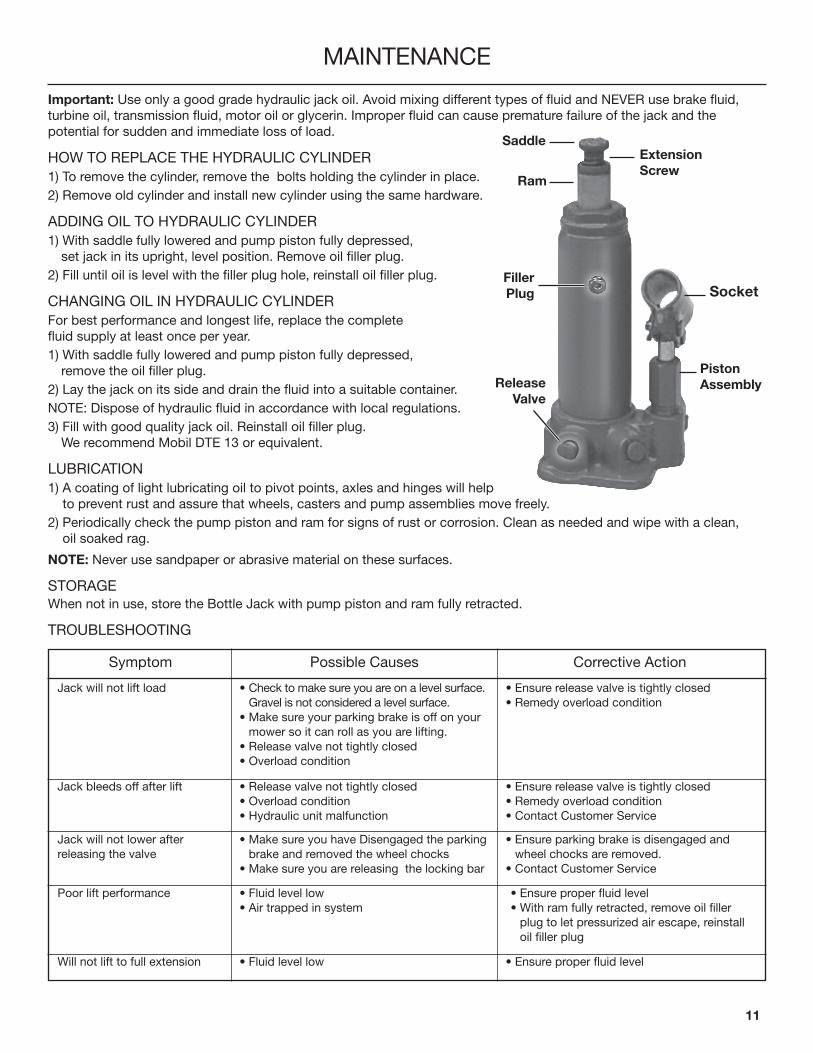
Important: Use only a good grade hydraulic jack oil. Avoid mixing different types of fluid and NEVER use brake fluid, turbine oil, transmission fluid, motor oil or glycerin. Improper fluid can cause premature failure of the jack and the potential for sudden and immediate loss of load.
HOW TO REPLACE THE HYDRAULIC CYLINDER 1) To remove the cylinder, remove the bolts holding the cylinder in place. 2) Remove old cylinder and install new cylinder using the same hardware.
ADDING OIL TO HYDRAULIC CYLINDER 1) With saddle fully lowered and pump piston fully depressed,
set jack in its upright, level position. Remove oil filler plug.2) Fill until oil is level with the filler plug hole, reinstall oil filler plug.
CHANGING OIL IN HYDRAULIC CYLINDERFor best performance and longest life, replace the complete fluid supply at least once per year.1) With saddle fully lowered and pump piston fully depressed,
remove the oil filler plug.2) Lay the jack on its side and drain the fluid into a suitable container.NOTE: Dispose of hydraulic fluid in accordance with local regulations.3) Fill with good quality jack oil. Reinstall oil filler plug.
We recommend Mobil DTE 13 or equivalent.
LUBRICATION1) A coating of light lubricating oil to pivot points, axles and hinges will help
to prevent rust and assure that wheels, casters and pump assemblies move freely.2) Periodically check the pump piston and ram for signs of rust or corrosion. Clean as needed and wipe with a clean,
oil soaked rag.
NOTE: Never use sandpaper or abrasive material on these surfaces.
STORAGEWhen not in use, store the Bottle Jack with pump piston and ram fully retracted.
TROUBLESHOOTING
Symptom Possible Causes Corrective Action
• Make sure you have Disengaged the parking brake and removed the wheel chocks
• Make sure you are releasing the locking bar
• Check to make sure you are on a level surface. Gravel is not considered a level surface.
• Make sure your parking brake is off on your mower so it can roll as you are lifting.
• Release valve not tightly closed• Overload condition
• Release valve not tightly closed• Overload condition• Hydraulic unit malfunction
• Fluid level low• Air trapped in system
• Fluid level low
• Ensure release valve is tightly closed• Remedy overload condition
• Ensure release valve is tightly closed• Remedy overload condition• Contact Customer Service
• Ensure parking brake is disengaged and wheel chocks are removed.
• Contact Customer Service
• Ensure proper fluid level
• Ensure proper fluid level• With ram fully retracted, remove oil filler
plug to let pressurized air escape, reinstall oil filler plug
Jack will not lift load
Will not lift to full extension
Jack bleeds off after lift
Jack will not lower after releasing the valve
Poor lift performance
ExtensionScrew
ReleaseValve
FillerPlug
PistonAssembly
Saddle
Ram
Socket

Manufactured By:
MoJack Distributors, LLC3535 N. Rock Rd.
Suite 300Wichita, KS 67226
1-877-575-3173
www.themojack.com