Embed Size (px)
Citation preview

WARNINGThe engine exhaust from this product contains chemicals known to the State of California to cause cancer, birth defects or other reproductive
WARNINGBefore using our products, please read this manual carefully to understand the proper use of your unit.
APPLICABLE SERIAL NUMBERS: 80100101 and up
Operator’s manual
130BT150BT/BF170BT/BF180BT/BF English
115 09 83-95
130BT&180BT_US-65.fm Page 1 Friday, December 7, 2007 1:05 PM

English
2
YOUR WARRANTY RIGHTS AND OBLIGATIONSThe EPA (The US Environmental Protection Agency), CARB (California Air Resources Board), Environment Canada and Husqvarna Forest & Garden are pleased to explain the emissions control system warranty on your 2007 and later small nonroad engine. In U.S. and Canada, new small nonroad engines must be designed, built and equipped to meet the federal stringent anti-smog standards. Husqvarna Forest & Garden must warrant the emission control system on your small nonroad engine for the period of time listed below provided there has been no abuse, neglect or improper maintenance of your unit. Your emission control system includes Parts such as the carburetor, fuel tank and the ignition system. Where a warrantable condition exists, Husqvarna Forest & Garden will repair your small nonroad engine at no cost to you. Expenses covered under warranty include diagnosis, parts and labor.
MANUFACTURER’S WAR-RANTY COVERAGEThe 2007 and later small nonroad engines are warranted for two years. If any emission related part on you engine (as listed above) is defective, the part will be repaired or replaced by Husqvarna Forest & Garden.
OWNER’S WARRANTY RESPONSIBILITIESAs the small nonroad engine owner, you are responsible for the performance of the required maintenance listed in your Operator’s Manual. Husqvarna Forest & Garden recommends that you retain all receipts covering maintenance on your small nonroad engine, but Husqvarna Forest & Garden cannot deny warranty solely for the lack of receipts or for your failure to ensure the performance of all scheduled maintenance. As the small nonroad engine owner, you should, however, be aware that Husqvarna Forest & Garden may deny you warranty coverage if your small nonroad engine or a part of it has failed due to abuse, neglect, improper maintenance, unapproved modifications or the use of parts not made or approved by the original equipment manufacturer. You are responsible for presenting your small nonroad engine to a Husqvarna Forest & Garden authorized servicing dealer as soon as a problem exists. The warranty repairs should be completed in a reasonable amount of time, not to exceed 30 days. If you have any questions regarding your warranty rights and responsibilities, you should contact your nearest authorized servicing dealer or call Husqvarna Forest & Garden at 1-800-487-5963.
WARRANTY COMMENCE-MENT DATEThe warranty period begins on the date small nonroad engine is delivered.
LENGTH OF COVERAGEHusqvarna Forest & Garden warrants to the initial owner and each subsequent purchaser that the engine is free from defects in materials and workmanship which cause the failure of a warranted part for a period of two years.
WHAT IS COVEREDREPAIR OR REPLACEMENT OF PARTS Repair or replacement of any warranted part will be performed at no charge to the owner at an approved Husqvarna Forest & Garden servicing dealer. If you have any questions regarding your warranty rights and
responsibilities, you should contact your nearest authorized servicing dealer or call Husqvarna Forest & Garden at 1-800-487-5963.
WARRANTY PERIOD Any warranted part which is not scheduled for replacement as required maintenance, or which is scheduled only for regular inspection to the effect of “repair or replace as necessary” shall be warranted for 2 years. Any warranted part which is scheduled for replacement as required maintenance shall be warranted for the period of time up to the first scheduled replacement point for that part.
DIAGNOSIS The owner shall not be charged for diagnostic labor which leads to the determination that a warranted part is defective, if the diagnostic work is performed at an approved Husqvarna Forest & Garden servicing dealer.
CONSEQUENTIAL DAMAGES Husqvarna Forest & Garden may be liable for damages to other engine components caused by the failure of a warranted part still under warranty.
WHAT IS NOT COVEREDAll failures caused by abuse, neglect or improper maintenance are not covered.
ADD -ON OR MODIFIED PARTSThe use of add-on or modified parts can be grounds for disallowing a warranty claim. Husqvarna Forest & Garden is not liable to cover failures of warranted parts caused by the use of add-on or modified parts.
HOW TO FILE A CLAIMIf you have any questions regarding your warranty rights and responsibilities, you should contact your nearest authorized servicing dealer or call Husqvarna Forest & Garden at 1-800-487-5963.
WHERE TO GET WARRANTY SERVICEWarranty services or repairs shall be provided at all Husqvarna Forest & Garden authorized servicing dealers.
MAINTENANCE, REPLACE-MENT AND REPAIR OF EMIS-SION-RELATED PARTSAny Husqvarna Forest & Garden approved replacement part used in the performance of any warranty maintenance or repairs on emission-related parts, will be provided without charge to the owner if the part is under warranty.
EMISSION CONTROL WAR-RANTY PARTS LIST1 Carburetor and internal parts2 Intake pipe, airfilter holder and carburetor bolts.3 Airfilter and fuelfilter covered up to maintenance
schedule.4 Ignition System
1Spark Plug, covered up to maintenance schedule2Ignition Module
5 Fuel tank with cap and pipe
MAINTENANCE STATEMENTThe owner is responsible for the performance of all required maintenance, as defined in the operator’s manual.
FEDERAL EMISSION CONTROL WARRANTY STATEMENT
130BT&180BT_US-65.fm Page 2 Friday, December 7, 2007 1:05 PM
English
3
Safety . . . . . . . . . . . . . . . . . . . . . . . . . . . . . . . . . . . . . . . . . . . . . . . . .4SAFETY FIRST . . . . . . . . . . . . . . . . . . . . . . . . . . . . . . . . . . . . . . . 4Notes on types of warnings . . . . . . . . . . . . . . . . . . . . . . . . . . . . . . 4
Warning labels on the machine . . . . . . . . . . . . . . . . . . . . . . . . . . . .4Symbols . . . . . . . . . . . . . . . . . . . . . . . . . . . . . . . . . . . . . . . . . . . . . 4
Symbols on the machine. . . . . . . . . . . . . . . . . . . . . . . . . . . . . . . . . .5
Safety Precautions. . . . . . . . . . . . . . . . . . . . . . . . . . . . . . . . . . . . . . .5WORKING CONDITIONS . . . . . . . . . . . . . . . . . . . . . . . . . . . . . . . 6WORKING CIRCUMSTANCE . . . . . . . . . . . . . . . . . . . . . . . . . . . . 6AVOID NOISE PROBLEM . . . . . . . . . . . . . . . . . . . . . . . . . . . . . . . 6WORKING PLAN . . . . . . . . . . . . . . . . . . . . . . . . . . . . . . . . . . . . . . 6FUEL . . . . . . . . . . . . . . . . . . . . . . . . . . . . . . . . . . . . . . . . . . . . . . . 6BEFORE STARTING THE ENGINE. . . . . . . . . . . . . . . . . . . . . . . . 7USING THE PRODUCT. . . . . . . . . . . . . . . . . . . . . . . . . . . . . . . . . 7MAINTENANCE . . . . . . . . . . . . . . . . . . . . . . . . . . . . . . . . . . . . . . . 8TRANSPORTATION. . . . . . . . . . . . . . . . . . . . . . . . . . . . . . . . . . . . 8STORAGE . . . . . . . . . . . . . . . . . . . . . . . . . . . . . . . . . . . . . . . . . . . 8
What is what?. . . . . . . . . . . . . . . . . . . . . . . . . . . . . . . . . . . . . . . . . . .9
Technical data . . . . . . . . . . . . . . . . . . . . . . . . . . . . . . . . . . . . . . . . .13
Assembly . . . . . . . . . . . . . . . . . . . . . . . . . . . . . . . . . . . . . . . . . . . . .14SWIVEL JOINT . . . . . . . . . . . . . . . . . . . . . . . . . . . . . . . . . . . . . . 14THROTTLE LEVER [130BT/150BT/170BT/180BT] . . . . . . . . . . . 14THROTTLE CABLE [130BT/150BT/170BT/180BT] . . . . . . . . . . . 14RIGHT HANDLE [150BF/170BF/180BF] . . . . . . . . . . . . . . . . . . . 14HANDLEBAR [OPTION] [130BT/150BT/170BT/180BT] . . . . . . . 14BLOWER TUBES. . . . . . . . . . . . . . . . . . . . . . . . . . . . . . . . . . . . . 15HARNESS . . . . . . . . . . . . . . . . . . . . . . . . . . . . . . . . . . . . . . . . . . 15WAIST BELT [150BT/BF] [170BT/BF] [180BT/BF]. . . . . . . . . . . . 15
Fuel . . . . . . . . . . . . . . . . . . . . . . . . . . . . . . . . . . . . . . . . . . . . . . . . . .16FUEL. . . . . . . . . . . . . . . . . . . . . . . . . . . . . . . . . . 16HOW TO MIX FUEL . . . . . . . . . . . . . . . . . . . . . . 16FUELING THE UNIT. . . . . . . . . . . . . . . . . . . . . . 16
Operation . . . . . . . . . . . . . . . . . . . . . . . . . . . . . . . . . . . . . . . . . . . . .17CONTROL ARM [150BF/170BF/180BF] . . . . . . 17STARTING ENGINE . . . . . . . . . . . . . . . . . . . . . . 17ADJUSTING IDLE SPEED . . . . . . . . . . . . . . . . . 18STOPPING ENGINE . . . . . . . . . . . . . . . . . . . . . 18
Maintenance . . . . . . . . . . . . . . . . . . . . . . . . . . . . . . . . . . . . . . . . . . .19AIR CLEANER . . . . . . . . . . . . . . . . . . . . . . . . . . 19FUEL FILTER . . . . . . . . . . . . . . . . . . . . . . . . . . . 20SPARK PLUG . . . . . . . . . . . . . . . . . . . . . . . . . . . 20MUFFLER. . . . . . . . . . . . . . . . . . . . . . . . . . . . . . 20SPARK ARRESTER . . . . . . . . . . . . . . . . . . . . . . 20AIR INLET NET . . . . . . . . . . . . . . . . . . . . . . . . . 21IGNITION COIL AIR GAP INSPECTION . . . . . . 21SHOLDER STRAP . . . . . . . . . . . . . . . . . . . . . . . 21
Storage . . . . . . . . . . . . . . . . . . . . . . . . . . . . . . . . . . . . . . . . . . . . . . .21
Contents
130BT&180BT_US-65.fm Page 3 Friday, December 7, 2007 1:05 PM
English
4
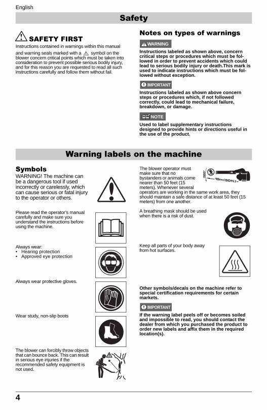
SAFETY FIRSTInstructions contained in warnings within this manual and warning seals marked with a symbol on the blower concern critical points which must be taken into consideration to prevent possible serious bodily injury, and for this reason you are requested to read all such instructions carefully and follow them without fail.
Notes on types of warnings WARNING
Instructions labeled as shown above, concern critical steps or procedures which must be fol-lowed in order to prevent accidents which could lead to serious bodily injury or death.This mark is used to indicate instructions which must be fol-lowed without exception.
IMPORTANT
Instructions labeled as shown above concern steps or procedures which, if not followed correctly, could lead to mechanical failure, breakdown, or damage.
NOTE
Used to label supplementary instructions designed to provide hints or directions useful in the use of the product.
SymbolsWARNING! The machine can be a dangerous tool if used incorrectly or carelessly, which can cause serious or fatal injury to the operator or others.
Please read the operator’s manual carefully and make sure you understand the instructions before using the machine.
Always wear:• Hearing protection• Approved eye protection
Always wear protective gloves.
Wear study, non-slip boots
The blower can forcibly throw objects that can bounce back. This can result in serious eye injuries if the recommended safety equipment is not used.
The blower operator must make sure that no bystanders or animals come nearer than 50 feet (15 meters). Whenever several operators are working in the same work area, they should maintain a safe distance of at least 50 feet (15 meters) from one another.
A breathing mask should be used when there is a risk of dust.
Keep all parts of your body away from hot surfaces.
Other symbols/decals on the machine refer to special certification requirements for certain markets.
IMPORTANT
If the warning label peels off or becomes soiled and impossible to read, you should contact the dealer from which you purchased the product to order new labels and affix them in the required location(s).
Warning labels on the machine
Safety
130BT&180BT_US-65.fm Page 4 Friday, December 7, 2007 1:05 PM
English
5
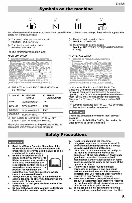
For safe operation and maintenance, symbols are carved in relief on the machine. Using to these indications, please be careful not to make a mistake.
(a) The port to refuel the "MIX GASOLINE" Position: FUEL TANK CAP
(b) The direction to close the chokePosition: INTAKE CUP
(c) The direction to open the chokePosition: INTAKE CUP
(d) The direction to stop the enginePosition: THROTTLE LEVER [130 BT/150 BT/170 BT only]
(e) The emission information label
∗1 : THE ACTUAL MANUFACTURING MONTH WILL BE PRINTED.
∗2 : THE INITIAL NUMBER WILL BE CHANGED EVERY YEAR OF MANUFACTURING.
This engine label certifies that the product is certified in accordance with American exhaust emissions
requirements EPA Ph II and CARB Tier III. The Emissions Compliance Period referred to on the emissions Compliance label indicates the number of operating hours for which the engine has been shown to meet Federal and California emission requirements. Category C = 50 hours, B = 125 hours, and A = 300 hours.For customer assistance call: 704-921-7000 or contact us at our website: www.husqvarna.com
IMPORTANT
Check the emission information label on your product.In the case of <FOR EPA ONLY>, the product is unsupported to use in California.
WARNING
1. Read this Blower Operator Manual carefully. Be sure you understand how to operate this unit properly before you use it. Failure to do so could result in serious injury.
2. Be sure to keep this manual handy so that you may refer to it later whenever any questions arise. Also note that you are requested to contact the dealer from whom you purchased the product for assistance the event that you have any questions which cannot be answered herein.
3. Always be sure to include this manual when selling, lending, or otherwise transferring the ownership of this product.
4. Do not lend or rent your machine without the owner's manul.
5. Be sure that anyone using your unit understands the information contained in this manual.
6. Never let a child use the machine.7. Long-term exposure to noise can result in
permanent hearing impairment. So always use approved hearing protection.
8. Under no circumstances may the design of the machine be modified without the permission of the manufacturer. Always use genuine accessories. Non-authorized modifications and/or accessories can result in serious personal injury or the death of the operator or others.
9. A blower is a dangerous tool if used carelessly or incorrectly and can cause serious, even fatal injuries. It is extremely important that you read and understand the contents of this Operator’s manual.
10. Husqvarna AB has a policy of continuous product development and therefore reserves the right to modify the design and appearance of products without prior notice.
11. The machine is only designed for blowing lawns, pathways, asphalt roads and the like.
(d)(a) (b) (c)
A
BC
A
BC
<FOR EPA ONLY> <FOR EPA & CARB>
A : Model B : ENGINE FAMILY
C : ENGINE DISPLACEMENT
130BT 7KZXS.0294BK ∗2 29cc
150BT/BF 7KZXS.0505BP ∗2 50cc
170BT/BF 7KZXS.0655BE ∗2 65cc
180BT/BF 8KZXS.0725PQ ∗2 72cc
Safety Precautions
Symbols on the machine
130BT&180BT_US-65.fm Page 5 Friday, December 7, 2007 1:05 PM
English
6
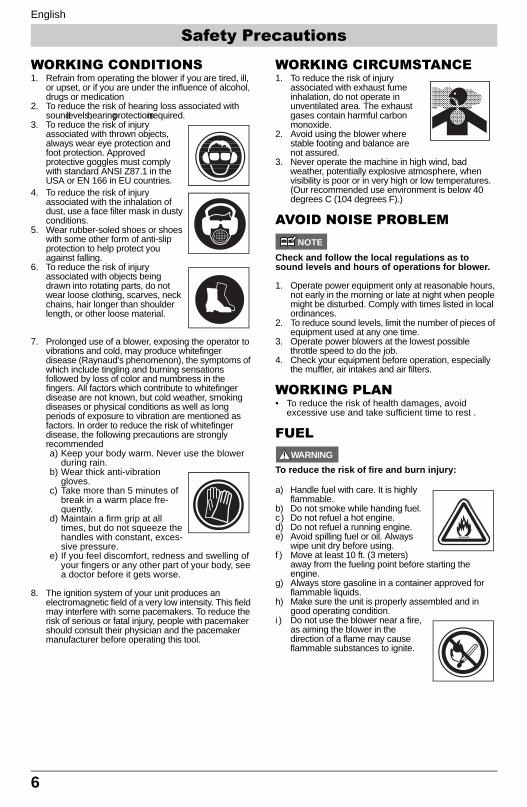
WORKING CONDITIONS1. Refrain from operating the blower if you are tired, ill,
or upset, or if you are under the influence of alcohol, drugs or medication
2. To reduce the risk of hearing loss associated with sound levels, hearing protection is required.
3. To reduce the risk of injury associated with thrown objects, always wear eye protection and foot protection. Approved protective goggles must comply with standard ANSI Z87.1 in the USA or EN 166 in EU countries.
4. To reduce the risk of injury associated with the inhalation of dust, use a face filter mask in dusty conditions.
5. Wear rubber-soled shoes or shoes with some other form of anti-slip protection to help protect you against falling.
6. To reduce the risk of injury associated with objects being drawn into rotating parts, do not wear loose clothing, scarves, neck chains, hair longer than shoulder length, or other loose material.
7. Prolonged use of a blower, exposing the operator to vibrations and cold, may produce whitefinger disease (Raynaud’s phenomenon), the symptoms of which include tingling and burning sensations followed by loss of color and numbness in the fingers. All factors which contribute to whitefinger disease are not known, but cold weather, smoking diseases or physical conditions as well as long periods of exposure to vibration are mentioned as factors. In order to reduce the risk of whitefinger disease, the following precautions are strongly recommendeda) Keep your body warm. Never use the blower
during rain.b) Wear thick anti-vibration
gloves. c) Take more than 5 minutes of
break in a warm place fre-quently.
d) Maintain a firm grip at all times, but do not squeeze the handles with constant, exces-sive pressure.
e) If you feel discomfort, redness and swelling of your fingers or any other part of your body, see a doctor before it gets worse.
8. The ignition system of your unit produces an electromagnetic field of a very low intensity. This field may interfere with some pacemakers. To reduce the risk of serious or fatal injury, people with pacemaker should consult their physician and the pacemaker manufacturer before operating this tool.
WORKING CIRCUMSTANCE1. To reduce the risk of injury
associated with exhaust fume inhalation, do not operate in unventilated area. The exhaust gases contain harmful carbon monoxide.
2. Avoid using the blower where stable footing and balance are not assured.
3. Never operate the machine in high wind, bad weather, potentially explosive atmosphere, when visibility is poor or in very high or low temperatures.(Our recommended use environment is below 40 degrees C (104 degrees F).)
AVOID NOISE PROBLEMNOTE
Check and follow the local regulations as to sound levels and hours of operations for blower.
1. Operate power equipment only at reasonable hours, not early in the morning or late at night when people might be disturbed. Comply with times listed in local ordinances.
2. To reduce sound levels, limit the number of pieces of equipment used at any one time.
3. Operate power blowers at the lowest possible throttle speed to do the job.
4. Check your equipment before operation, especially the muffler, air intakes and air filters.
WORKING PLAN• To reduce the risk of health damages, avoid
excessive use and take sufficient time to rest .
FUELWARNING
To reduce the risk of fire and burn injury:
a) Handle fuel with care. It is highly flammable.
b) Do not smoke while handing fuel.c) Do not refuel a hot engine.d) Do not refuel a running engine. e) Avoid spilling fuel or oil. Always
wipe unit dry before using. f ) Move at least 10 ft. (3 meters)
away from the fueling point before starting the engine.
g) Always store gasoline in a container approved for flammable liquids.
h) Make sure the unit is properly assembled and in good operating condition.
i ) Do not use the blower near a fire, as aiming the blower in the direction of a flame may cause flammable substances to ignite.
Safety Precautions
130BT&180BT_US-65.fm Page 6 Friday, December 7, 2007 1:05 PM
English
7
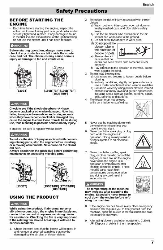
BEFORE STARTING THE ENGINE• Each time before starting the engine, inspect the
entire unit to see if every part is in good order and is securely tightened in place. If any damage is found in the fuel line, the exhaust line, or the ignition wiring, do not use the blower until it has been repaired.
IMPORTANT
Before starting operation, always make sure to check if any obstacles are left inside the volute case and net. The obstacles may cause serious injury or damage to fan and volute case.
WARNING
Check to see if the shock-absorbers <A> have become cracked or otherwise damaged. Note that failing to replace these rubber and spring mounts when they have become cracked or damaged may cause the engine to come loose from its frame during use, thus resulting in possible serious bodily injury.
If cracked, be sure to replace without delay.
WARNING
To reduce the risk of injury associated with contact-ing rotating parts, stop the engine before installing or removing attachments. Never take off the Guard Net <B>. Always disconnect the spark plug before performing maintenance or accessing movable parts.
USING THE PRODUCTWARNING
While using the product, if abnormal noise or vibration occurs, stop the engine immediately and contact the nearest Husqvarna servicing dealer for assistance. Checking the fan is very important. If the rotating fan should break up, it will lead to serious accidents.
1. Check the work area that the blower will be used in and remove or cover all valuables that may be damaged by the air blast or thrown debris.
2. To reduce the risk of injury associated with thrown objects.a) Watch out for children, pets, open windows or
freshly washed cars, and blow debris safely away.
b) Use the full blower tube extension so the air stream can work close to the ground.
c) Do not allow bystanders in work area.d) Do not point the
blower tube in the direction of people or pets.
e) Always check to be sure that no debris has been blown onto someone else’s property.
f) Pay attention to the direction of the wind, do not work against the wind.
3. To minimize blowing time.a) Use rakes and brooms to loosen debris before
blowing.b) In dusty conditions, slightly dampen surfaces or
use a mister attachment when water is available.c) Conserve water by using power blowers instead
of hoses for many lawn and garden applications, including areas such as gutters, screens, patios, grills, porches and gardens.
4. The blower must not be used while on a ladder or scaffolding.
5. Never put the machine down with the engine running unless you have it in clear sight.
6. Never touch the spark plug or plug cord while the engine is in operation. Doing so may result in being subjected to an electrical shock.
7. Never touch the muffler, spark plug, or other metallic parts of the engine, or area around the engine cover while the engine is in operation or immediately after shutting down the engine. These metallic parts reach high temperatures during operation and doing so could result in serious burns.
WARNING
The temperature of the machine may increase after stopping the engine. Especially never forget to cool down the engine before refu-eling the machine.
8. If the engine catches fire or in any other emergency situation that requires you to free yourself from the machine, open the buckle in the waist belt and drop the machine backward.
9. After using blowers and other equipment, CLEAN UP! Dispose of debris in trash receptacles.
[150BT/BF] [170BT/BF] [180BT/BF]
[130BT]
<A>
<A>
<B>
<A>
<A>
<B>
[130BT] [150BT/BF] [170BT/BF][180BT/BF]
Safety Precautions
130BT&180BT_US-65.fm 7 ページ 2008年3月21日 金曜日 午後1時6分
English
8
MAINTENANCE1. In order to maintain your product in proper working
order, perform the maintenance and checking operations described in the manual at regular intervals.
2. Always be sure to turn off the engine and disconnect the spark plug before performing any maintenance or checking procedures.
WARNING
The metallic parts, engine cover, and area around the engine reach high temperatures immediately after stopping the engine.
3. Examine the blower at intervals for loose fasteners and rusted or damaged parts. Use special care around the fuel line, the muffler, and the ignition wiring.
4. All engine service except for those described in this manual should be performed by competent service personnel. Improper service to the blower fan and muffler could cause a hazardous failure.
5. When replacing the any other part or any lubricant, always be sure to use only Husqvarna products or products which have been certified by Husqvarna for use with the Husqvarna product.
6. In the event that any part must be replaced or any maintenance or repair work not described in this manual must be performed, please contact the nearest Husqvarna servicing dealer for assistance.
7. Do not use any accessory or attachment other than those bearing the Husqvarna mark and recommended for the unit.
8. Under no circumstances should you ever take apart the product or alter it in any way. Doing so might result in the product becoming damaged during operation or the product becoming unable to operate properly.
TRANSPORTATION• Drain the fuel from the fuel tank before transporting
or storing the blower.• Secure the blower so that it does nor receive
damage from shock doing transportation.• Do not apply strong forces to the blower, such as
throwing it or dropping it. Doing so in validates the warranty.
STORAGE• When storing the blower, choose a space indoors,
dry, cool and dark, well-ventilated, free from dust and out of reach of children.
Safety Precautions
130BT&180BT_US-65.fm Page 8 Friday, December 7, 2007 1:05 PM
English
9
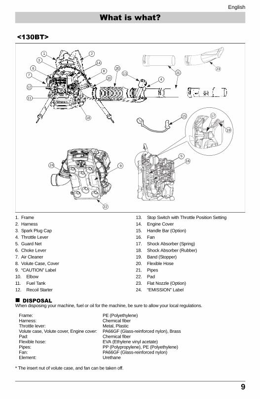
1. Frame2. Harness3. Spark Plug Cap4. Throttle Lever5. Guard Net6. Choke Lever7. Air Cleaner8. Volute Case, Cover9. “CAUTION” Label10. Elbow11. Fuel Tank12. Recoil Starter
13. Stop Switch with Throttle Position Setting14. Engine Cover15. Handle Bar (Option)16. Fan17. Shock Absorber (Spring)18. Shock Absorber (Rubber)19. Band (Stopper)20. Flexible Hose21. Pipes22. Pad23. Flat Nozzle (Option)24. “EMISSION” Label
DISPOSALWhen disposing your machine, fuel or oil for the machine, be sure to allow your local regulations.
Frame: PE (Polyethylene)Harness: Chemical fiber Throttle lever: Metal, Plastic Volute case, Volute cover, Engine cover: PA66GF (Glass-reinforced nylon), BrassPad: Chemical fiberFlexible hose: EVA (Ethylene vinyl acetate)Pipes: PP (Polypropylene), PE (Polyethylene)Fan: PA66GF (Glass-reinforced nylon)Element: Urethane
* The insert nut of volute case, and fan can be taken off.
<130BT>
15
14
2
8
10
1
3
6
7
24
12
11
4
13
2021
516
18 17
19
9
22
23
What is what?
130BT&180BT_US-65.fm Page 9 Friday, December 7, 2007 1:05 PM
English
10
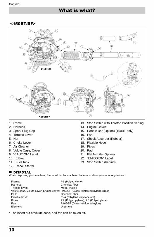
1. Frame2. Harness3. Spark Plug Cap4. Throttle Lever5. Net6. Choke Lever7. Air Cleaner8. Volute Case, Cover9. “CAUTION” Label10. Elbow11. Fuel Tank12. Recoil Starter
13. Stop Switch with Throttle Position Setting14. Engine Cover15. Handle Bar (Option) (150BT only)16. Fan17. Shock Absorber (Rubber)18. Flexible Hose19. Pipes20. Pad21. Flat Nozzle (Option)22. “EMISSION” Label23. Stop Switch (behind)
DISPOSALWhen disposing your machine, fuel or oil for the machine, be sure to allow your local regulations.
Frame: PE (Polyethylene)Harness: Chemical fiber Throttle lever: Metal, Plastic Volute case, Volute cover, Engine cover: PA66GF (Glass-reinforced nylon), BrassPad: Chemical fiberFlexible hose: EVA (Ethylene vinyl acetate)Pipes: PP (Polypropylene), PE (Polyethylene)Fan: PA66GF (Glass-reinforced nylon)Element: Urethane
* The insert nut of volute case, and fan can be taken off.
9
20
21
234
14
2
8
10
1
3
6
7
12
11
413
18
19
17
15
16
5
22
<150BT/BF>
<150BT>
<150BF>
What is what?
130BT&180BT_US-65.fm Page 10 Friday, December 7, 2007 1:05 PM
English
11
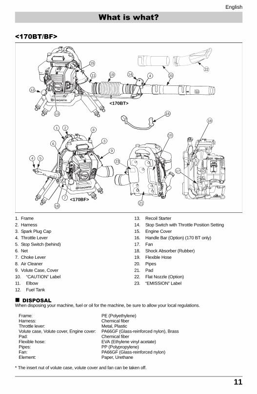
1. Frame2. Harness3. Spark Plug Cap4. Throttle Lever5. Stop Switch (behind)6. Net 7. Choke Lever8. Air Cleaner9. Volute Case, Cover10. “CAUTION” Label11. Elbow12. Fuel Tank
13. Recoil Starter14. Stop Switch with Throttle Position Setting15. Engine Cover16. Handle Bar (Option) (170 BT only)17. Fan18. Shock Absorber (Rubber)19. Flexible Hose20. Pipes21. Pad22. Flat Nozzle (Option)23. “EMISSION” Label
DISPOSALWhen disposing your machine, fuel or oil for the machine, be sure to allow your local regulations.
Frame: PE (Polyethylene)Harness: Chemical fiber Throttle lever: Metal, Plastic Volute case, Volute cover, Engine cover: PA66GF (Glass-reinforced nylon), BrassPad: Chemical fiberFlexible hose: EVA (Ethylene vinyl acetate)Pipes: PP (Polypropylene)Fan: PA66GF (Glass-reinforced nylon)Element: Paper, Urethane
* The insert nut of volute case, volute cover and fan can be taken off.
8
3
9
12
16
1 2
6
7
13
15
11 14 4
54
17
10
18
18
19 20
21
22
23
<170BT>
<170BF>
<170BT/BF>
What is what?
130BT&180BT_US-65.fm Page 11 Friday, December 7, 2007 1:05 PM
English
12
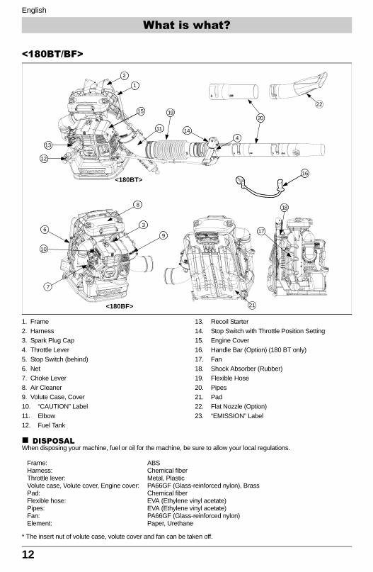
1. Frame2. Harness3. Spark Plug Cap4. Throttle Lever5. Stop Switch (behind)6. Net 7. Choke Lever8. Air Cleaner9. Volute Case, Cover10. “CAUTION” Label11. Elbow12. Fuel Tank
13. Recoil Starter14. Stop Switch with Throttle Position Setting15. Engine Cover16. Handle Bar (Option) (180 BT only)17. Fan18. Shock Absorber (Rubber)19. Flexible Hose20. Pipes21. Pad22. Flat Nozzle (Option)23. “EMISSION” Label
DISPOSALWhen disposing your machine, fuel or oil for the machine, be sure to allow your local regulations.
Frame: ABSHarness: Chemical fiber Throttle lever: Metal, Plastic Volute case, Volute cover, Engine cover: PA66GF (Glass-reinforced nylon), BrassPad: Chemical fiberFlexible hose: EVA (Ethylene vinyl acetate)Pipes: EVA (Ethylene vinyl acetate)Fan: PA66GF (Glass-reinforced nylon)Element: Paper, Urethane
* The insert nut of volute case, volute cover and fan can be taken off.
16
15
1
2
10
6
7
13
12
41411
18
9
3
8
22
21
17
2019
<180BT>
<180BF>
<180BT/BF>
What is what?
130BT&180BT_US-65.fm Page 12 Friday, December 7, 2007 1:05 PM
English
13
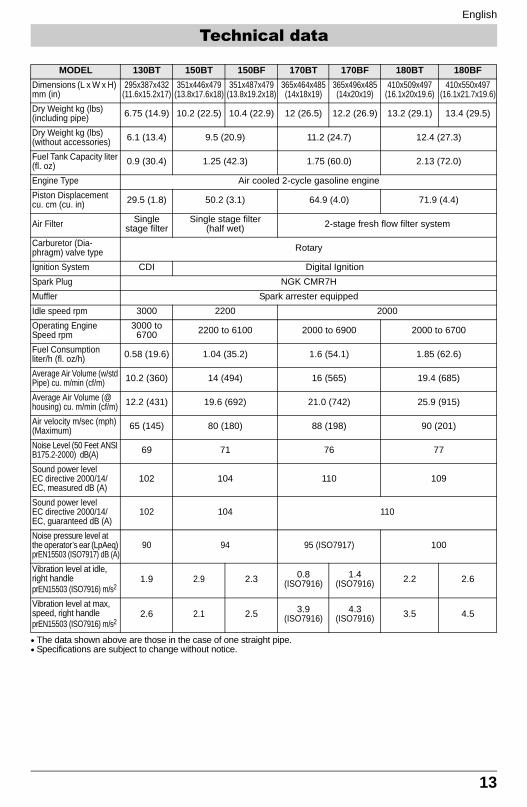
• The data shown above are those in the case of one straight pipe.• Specifications are subject to change without notice.
MODEL 130BT 150BT 150BF 170BT 170BF 180BT 180BFDimensions (L x W x H) mm (in)
295x387x432 (11.6x15.2x17)
351x446x479 (13.8x17.6x18)
351x487x479 (13.8x19.2x18)
365x464x485(14x18x19)
365x496x485(14x20x19)
410x509x497(16.1x20x19.6)
410x550x497(16.1x21.7x19.6)
Dry Weight kg (lbs) (including pipe) 6.75 (14.9) 10.2 (22.5) 10.4 (22.9) 12 (26.5) 12.2 (26.9) 13.2 (29.1) 13.4 (29.5)
Dry Weight kg (lbs) (without accessories) 6.1 (13.4) 9.5 (20.9) 11.2 (24.7) 12.4 (27.3)
Fuel Tank Capacity liter (fl. oz) 0.9 (30.4) 1.25 (42.3) 1.75 (60.0) 2.13 (72.0)
Engine Type Air cooled 2-cycle gasoline enginePiston Displacement cu. cm (cu. in) 29.5 (1.8) 50.2 (3.1) 64.9 (4.0) 71.9 (4.4)
Air Filter Single stage filter
Single stage filter (half wet) 2-stage fresh flow filter system
Carburetor (Dia-phragm) valve type Rotary
Ignition System CDI Digital IgnitionSpark Plug NGK CMR7HMuffler Spark arrester equippedIdle speed rpm 3000 2200 2000Operating Engine Speed rpm
3000 to 6700 2200 to 6100 2000 to 6900 2000 to 6700
Fuel Consumption liter/h (fl. oz/h) 0.58 (19.6) 1.04 (35.2) 1.6 (54.1) 1.85 (62.6)
Average Air Volume (w/std Pipe) cu. m/min (cf/m) 10.2 (360) 14 (494) 16 (565) 19.4 (685)
Average Air Volume (@ housing) cu. m/min (cf/m) 12.2 (431) 19.6 (692) 21.0 (742) 25.9 (915)
Air velocity m/sec (mph) (Maximum) 65 (145) 80 (180) 88 (198) 90 (201)
Noise Level (50 Feet ANSI B175.2-2000) dB(A) 69 71 76 77
Sound power level EC directive 2000/14/EC, measured dB (A)
102 104 110 109
Sound power level EC directive 2000/14/EC, guaranteed dB (A)
102 104 110
Noise pressure level at the operator’s ear (LpAeq) prEN15503 (ISO7917) dB (A)
90 94 95 (ISO7917) 100
Vibration level at idle, right handle prEN15503 (ISO7916) m/s2
1.9 2.9 2.3 0.8 (ISO7916)
1.4 (ISO7916) 2.2 2.6
Vibration level at max, speed, right handle prEN15503 (ISO7916) m/s2
2.6 2.1 2.5 3.9 (ISO7916)
4.3 (ISO7916) 3.5 4.5
Technical data
130BT&180BT_US-65.fm 13 ページ 2008年3月21日 金曜日 午後1時6分
English
14
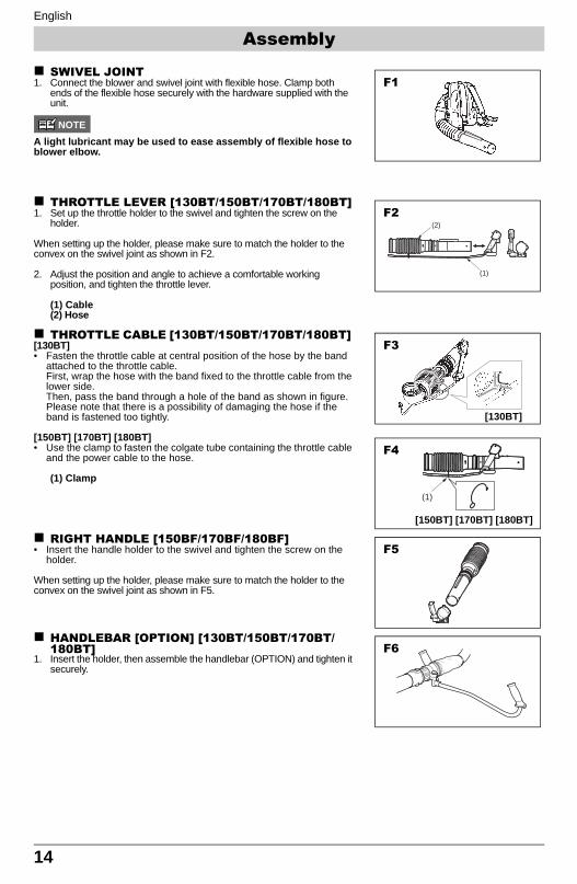
SWIVEL JOINT1. Connect the blower and swivel joint with flexible hose. Clamp both
ends of the flexible hose securely with the hardware supplied with the unit.
NOTE
A light lubricant may be used to ease assembly of flexible hose to blower elbow.
THROTTLE LEVER [130BT/150BT/170BT/180BT]1. Set up the throttle holder to the swivel and tighten the screw on the
holder.
When setting up the holder, please make sure to match the holder to the convex on the swivel joint as shown in F2.
2. Adjust the position and angle to achieve a comfortable working position, and tighten the throttle lever.
(1) Cable(2) Hose
THROTTLE CABLE [130BT/150BT/170BT/180BT] [130BT]• Fasten the throttle cable at central position of the hose by the band
attached to the throttle cable.First, wrap the hose with the band fixed to the throttle cable from the lower side.Then, pass the band through a hole of the band as shown in figure.Please note that there is a possibility of damaging the hose if the band is fastened too tightly.
[150BT] [170BT] [180BT] • Use the clamp to fasten the colgate tube containing the throttle cable
and the power cable to the hose.
(1) Clamp
RIGHT HANDLE [150BF/170BF/180BF] • Insert the handle holder to the swivel and tighten the screw on the
holder.
When setting up the holder, please make sure to match the holder to the convex on the swivel joint as shown in F5.
HANDLEBAR [OPTION] [130BT/150BT/170BT/180BT]
1. Insert the holder, then assemble the handlebar (OPTION) and tighten it securely.
F1
(1)
(2)
F2
F3
[130BT]
(1)
F4
[150BT] [170BT] [180BT]
F5
F6
Assembly
130BT&180BT_US-65.fm Page 14 Friday, December 7, 2007 1:05 PM
English
15
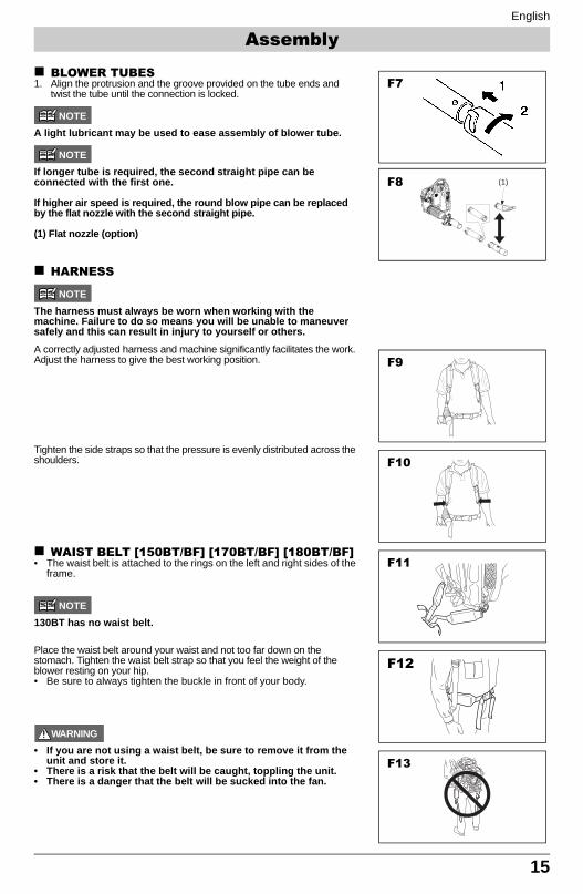
BLOWER TUBES1. Align the protrusion and the groove provided on the tube ends and
twist the tube until the connection is locked.
NOTE
A light lubricant may be used to ease assembly of blower tube.
NOTE
If longer tube is required, the second straight pipe can be connected with the first one.
If higher air speed is required, the round blow pipe can be replaced by the flat nozzle with the second straight pipe.
(1) Flat nozzle (option)
HARNESS
NOTE
The harness must always be worn when working with the machine. Failure to do so means you will be unable to maneuver safely and this can result in injury to yourself or others.A correctly adjusted harness and machine significantly facilitates the work. Adjust the harness to give the best working position.
Tighten the side straps so that the pressure is evenly distributed across the shoulders.
WAIST BELT [150BT/BF] [170BT/BF] [180BT/BF]• The waist belt is attached to the rings on the left and right sides of the
frame.
NOTE
130BT has no waist belt.
Place the waist belt around your waist and not too far down on the stomach. Tighten the waist belt strap so that you feel the weight of the blower resting on your hip.• Be sure to always tighten the buckle in front of your body.
WARNING
• If you are not using a waist belt, be sure to remove it from the unit and store it.
• There is a risk that the belt will be caught, toppling the unit.• There is a danger that the belt will be sucked into the fan.
F7
F8 (1)
F9
F10
F11
F12
F13
Assembly
130BT&180BT_US-65.fm 15 ページ 2008年3月21日 金曜日 午後1時6分
English
16
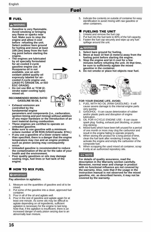
FUEL
WARNING
• Gasoline is very flammable. Avoid smoking or bringing any flame or sparks near fuel. Make sure to stop the engine and allow it cool before refueling the unit. Select outdoor bare ground for fueling and move at least 10ft (3m) away from the fuel-ing point before starting the engine.
• The engines are lubricated by oil specially formulated for air-cooled 2-cycle gasoline engine use. If Husqvarna oil is not available, use an anti-oxidant added quality oil expressly labeled for air-cooled 2-cycle engine use. (JASO FC GRADE OIL or ISO EGC GRADE)
• Do not use BIA or TCW (2-stroke water-cooling type) mixed oil.
RECOMMENDED MIXING RATIOGASOLINE 50:OIL 1
• Exhaust emission are controlled by the fundamental engine parameters and components (i.e., carburation, ignition timing and port timing) without addition of any major hardware or the introduction of an inert material during combustion.
• These engines are certified to operate on unleaded gasoline.
• Make sure to use gasoline with a minimum octane number of 89 RON (USA/Canada: 87AL)
• If you use a gasoline of a lower octane value than specified, there is a danger that the engine temperature may rise and an engine problem such as piston seizing may consequently occur.
• Unleaded gasoline is recommended to reduce the contamination of the air for the sake of your health and the environment.
• Poor quality gasolines or oils may damage sealing rings, fuel lines or fuel tank of the engine.
HOW TO MIX FUEL
IMPORTANT
Pay attention to agitation.
1. Measure out the quantities of gasoline and oil to be mixed.
2. Put some of the gasoline into a clean, approved fuel container.
3. Pour in all of the oil and agitate well.4. Pour in the rest of gasoline and agitate again for at
least one minute. As some oils may be difficult to agitate depending on oil ingredients, sufficient agitation is necessary for the engine to last long. Note that, if the agitation is insufficient, there is an increased danger of early piston seizing due to an abnormally lean mixture.
5. Indicate the contents on outside of container for easy identification to avoid mixing with raw gasoline or other containers.
FUELING THE UNIT1. Untwist and remove the fuel cap. 2. Put fuel into the fuel tank to 80% of the full capacity.3. Fasten the fuel cap securely and wipe up any fuel
spillage around the unit.
WARNING
1. Select bare ground for fueling.2. Move at least 10 feet (3 meters) away from the
fueling point before starting the engine.3. Stop the engine and let it cool for a few
minutes before refueling the unit. At that time, be sure to sufficiently agitate the mixed gasoline in the container.
4. Do not smoke or place hot objects near fuel.
FOR YOUR ENGINE LIFE, AVOID;1. FUEL WITH NO OIL (RAW GASOLINE) - It will
cause severe damage to the internal engine parts very quickly.
2. GASOHOL - It can cause deterioration of rubber and/or plastic parts and disruption of engine lubrication.
3. OIL FOR 4-CYCLE ENGINE USE - It can cause spark plug fouling, exhaust port blocking, or piston ring sticking.
4. Mixed fuels which have been left unused for a period of one month or more may clog the carburetor and result in the engine failing to operate properly.
5. When storing the product for a long period of time, clean the fuel tank after rendering it empty. Next, activate the engine and empty the carburetor of the composite fuel.
6. When scrapping the used mixed oil container, scrap it only at an authorized repository site.
NOTE
For details of quality assurance, read the description in the Warranty section carefully. Moreover, normal wear and change in product with no functional influence are not covered by the warranty. Also, note that if the usage in the instruction manual is not observed for the mixed gasoline, etc. as described herein, it may not be covered by the warranty.
Fuel
130BT&180BT_US-65.fm Page 16 Friday, December 7, 2007 1:05 PM
English
17
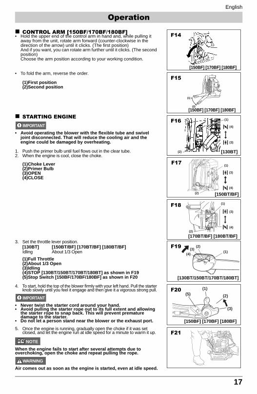
CONTROL ARM [150BF/170BF/180BF]• Hold the upper end of the control arm in hand and, while pulling it
away from the unit, rotate arm forward (counter-clockwise in the direction of the arrow) until it clicks. (The first position) And if you want, you can rotate arm further until it clicks. (The second position) Choose the arm position according to your working condition.
• To fold the arm, reverse the order.
(1)First position(2)Second position
STARTING ENGINEIMPORTANT
• Avoid operating the blower with the flexible tube and swivel joint disconnected. That will reduce the cooling air and the engine could be damaged by overheating.
1. Push the primer bulb until fuel flows out in the clear tube.2. When the engine is cool, close the choke.
(1)Choke Lever(2)Primer Bulb(3)OPEN(4)CLOSE
3. Set the throttle lever position.[130BT] [150BT/BF] [170BT/BF] [180BT/BF]Idling About 1/3 Open(1)Full Throttle(2)About 1/3 Open(3)Idling(4)STOP [130BT/150BT/170BT/180BT] as shown in F19(5)Stop Switch [150BF/170BF/180BF] as shown in F20
4. To start, hold the top of the blower firmly with your left hand. Pull the starter knob slowly until you feel it engage and then give it a vigorous strong pull.
IMPORTANT
• Never twist the starter cord around your hand.• Avoid pulling the starter rope out to its full extent and allowing
the starter rope to snap back. This will prevent premature damage to the starter.
• Do not let a person stand near the blower or the exhaust port. 5. Once the engine is running, gradually open the choke if it was set
closed, and let the engine run at idle speed for a minute to warm it up.
NOTE
When the engine fails to start after several attempts due to overchoking, open the choke and repeat pulling the rope.
WARNING
Air comes out as soon as the engine is started, even at idle speed.
F14
[150BF] [170BF] [180BF]
(1)
(2)
F15
[150BF] [170BF] [180BF]
(1)
(2)
(3)
(4)
F16
(1)
(2)
(3)
(4)
F18
[130BT]
[170BT/BF] [180BT/BF]
F17(1)
(2)
(4)
(3)
[150BT/BF]
(1)
(2)(3)
(4)
F19
[130BT/150BT/170BT/180BT]
(1)
(2)
(3)
(5)
[150BF] [170BF] [180BF]
F21
F20
Operation
130BT&180BT_US-65.fm Page 17 Friday, December 7, 2007 1:05 PM
English
18
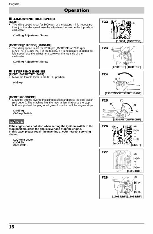
ADJUSTING IDLE SPEED[130BT]• The idling speed is set for 3000 rpm at the factory. If it is necessary
to adjust the idle speed, use the adjustment screw on the top side of carburetor.
(1)Idling Adjustment Screw
[150BT/BF] [170BT/BF] [180BT/BF]• The idling speed is set for 2200 rpm [150BT/BF] or 2000 rpm
[170BT/BF] [180BT/BF] at the factory. If it is necessary to adjust the idle speed, use the adjustment screw on the top side of the carburetor.
(1)Idling Adjustment Screw
STOPPING ENGINE[130BT/150BT/170BT/180BT]• Move the throttle lever to the STOP position.
(4)Stop
[150BF/170BF/180BF]• Move the throttle lever to the idling position and press the stop switch
(red button). The machine has the mechanism that once the stop button is pushed the plug won't give off sparks until the engine stops.
(3)Idling(5)Stop Switch
NOTE
If the engine does not stop when setting the ignition switch to the stop position, close the choke lever and stop the engine.In this case, please repair the machine at your nearest servicing dealer.
(1)Choke Lever(2)OPEN(3)CLOSE
(1)F22
[130BT] [150BT/BF]
(1)F23
[170BT/BF] [180BT/BF]
(1)
(2)(3)
(4)
F24
[130BT/150BT/170BT/180BT]
(1)
(2)
(4)
(3)
(1)
(2)
(3)
(5)F25
[150BF/170BF/180BF]
F27
(1)
(2)
(3)
F26
[130BT]
[150BT/BF]
(1)
(2)
(3)
F28
[170BT/BF] [180BT/BF]
Operation
130BT&180BT_US-65.fm Page 18 Friday, December 7, 2007 1:05 PM
English
19
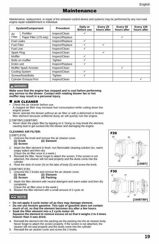
Maintenance, replacement, or repair of the emission control device and systems may be performed by any non-road engine repair establishment or individual.
WARNING
Make sure that the engine has stopped and is cool before performing any service to the blower. Contact with rotating blower fan or hot muffler may result in a personal injury.
AIR CLEANER• Check the air cleaner before use.
A clogged air filter may increase fuel consumption while cutting down the engine power.
• Never operate the blower without an air filter or with a deformed or broken filter element because unfiltered dusty air will quickly ruin the engine.
[170BT/BF] [180BT/BF]• Never clean the paper filter by tapping on it. Doing so may break the element,
causing dust to get sucked into the blower and damaging the engine.
CLEANING AIR FILTER:[130BT] (F29)1. Unscrew the knob and remove the air cleaner cover.
(1) Knob (2) Element(3) Screen
2. Wash the filter element in fresh, non flammable cleaning solution (ex. warm soapy water) and then dry.(Clean the air filter once in a week.)
3. Reinstall the filter. Never forget to attach the screen. If the screen is not attached, the cleaner will not seal properly and the dusts come into the cylinder.
4. Hook the slots of cover (4) on the tabs of body (5) and screw the knob.[150BT/BF] (F30)1. Unscrew the 2 knobs and remove the air cleaner cover.
(1) Knob (2) Element(3) Screen (4) Packing
2. Wash the filter element with neutral detergent and warm water and then dry completely.(Clean the air filter once in the week.)
3. Moisten the filter element with a small amount of 2 cycle oil.
NOTE
• Do not apply 4 cycle motor oil as they may damage element.• Do not use mixture gasoline. This type of gasoline does not contain
much of oil, so that the element becomes dry after a few hours.• Soak the filter element into a 2 cycle motor oil.
Squeeze the element to remove excess oil so that it weighs 2 to 3 times heavier than it was dried.
4. Reinstall the element into the packing,set the packing into the air cleaner body. Never forget to attach the screen properly. If the screen is not attached, the cleaner will not seal properly and the dusts come into the cylinder.
5. Reinstall the air cleaner cover and screw the 2 knobs.
System/Compornent Procedure Daily or Before use
Every 25 hours after
Every 50 hours after
Every 100 hours after
Air Filter
Prefilter Inspect/CleanPaper Filter (170 only) Inspect/Replace
Fuel Leaks Inspect/ReplaceFuel Filter Inspect/ReplaceFuel Line Inspect/CleanSpark Plug Inspect/CleanMuffler Inspect/CleanBolts on muffler TightenEntire unit Inspect/ReplaceMuffler Spark Arrester Inspect/CleanCooling System Inspect/CleanScrews/Nuts/Bolts TightenCylinder Exhaust Port Inspect/Clean
(3)(4)
(2)(1)
(3)
(5)(4)
(1) (2)
F29
[130BT]
F30
[150BT/BF]
Maintenance
130BT&180BT_US-65.fm Page 19 Friday, December 7, 2007 1:05 PM
English
20
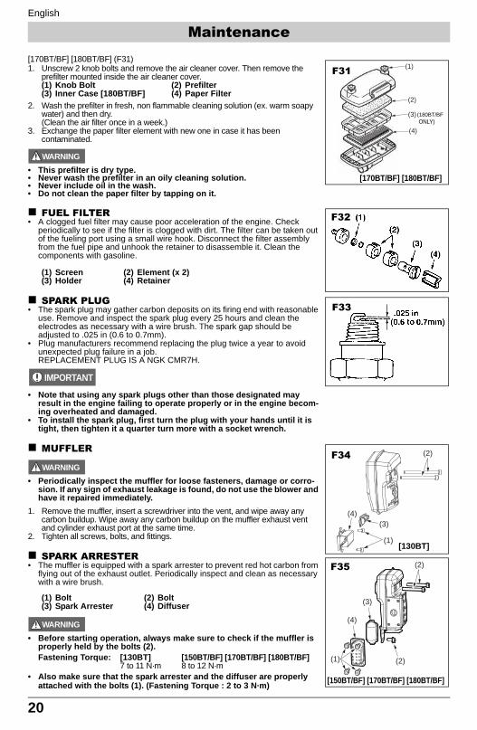
[170BT/BF] [180BT/BF] (F31)1. Unscrew 2 knob bolts and remove the air cleaner cover. Then remove the
prefilter mounted inside the air cleaner cover. (1) Knob Bolt (2) Prefilter(3) Inner Case [180BT/BF] (4) Paper Filter
2. Wash the prefilter in fresh, non flammable cleaning solution (ex. warm soapy water) and then dry.(Clean the air filter once in a week.)
3. Exchange the paper filter element with new one in case it has been contaminated.
WARNING
• This prefilter is dry type.• Never wash the prefilter in an oily cleaning solution.• Never include oil in the wash.• Do not clean the paper filter by tapping on it.
FUEL FILTER• A clogged fuel filter may cause poor acceleration of the engine. Check
periodically to see if the filter is clogged with dirt. The filter can be taken out of the fueling port using a small wire hook. Disconnect the filter assembly from the fuel pipe and unhook the retainer to disassemble it. Clean the components with gasoline.
(1) Screen (2) Element (x 2)(3) Holder (4) Retainer
SPARK PLUG• The spark plug may gather carbon deposits on its firing end with reasonable
use. Remove and inspect the spark plug every 25 hours and clean the electrodes as necessary with a wire brush. The spark gap should be adjusted to .025 in (0.6 to 0.7mm).
• Plug manufacturers recommend replacing the plug twice a year to avoid unexpected plug failure in a job.REPLACEMENT PLUG IS A NGK CMR7H.
IMPORTANT
• Note that using any spark plugs other than those designated may result in the engine failing to operate properly or in the engine becom-ing overheated and damaged.
• To install the spark plug, first turn the plug with your hands until it is tight, then tighten it a quarter turn more with a socket wrench.
MUFFLER
WARNING
• Periodically inspect the muffler for loose fasteners, damage or corro-sion. If any sign of exhaust leakage is found, do not use the blower and have it repaired immediately.
1. Remove the muffler, insert a screwdriver into the vent, and wipe away any carbon buildup. Wipe away any carbon buildup on the muffler exhaust vent and cylinder exhaust port at the same time.
2. Tighten all screws, bolts, and fittings.
SPARK ARRESTER• The muffler is equipped with a spark arrester to prevent red hot carbon from
flying out of the exhaust outlet. Periodically inspect and clean as necessary with a wire brush.
(1) Bolt (2) Bolt(3) Spark Arrester (4) Diffuser
WARNING
• Before starting operation, always make sure to check if the muffler is properly held by the bolts (2). Fastening Torque: [130BT] [150BT/BF] [170BT/BF] [180BT/BF]
7 to 11 N·m 8 to 12 N·m• Also make sure that the spark arrester and the diffuser are properly
attached with the bolts (1). (Fastening Torque : 2 to 3 N·m)
(1)
(2)
(3)
(4)
F31
[170BT/BF] [180BT/BF]
(180BT/BFONLY)
F32
F33
(2)
(1) (2)
(4)
(3)
(2)
(4)(3)
(1)
F35
F34
[150BT/BF] [170BT/BF] [180BT/BF]
[130BT]
Maintenance
130BT&180BT_US-65.fm Page 20 Friday, December 7, 2007 1:05 PM
English
21
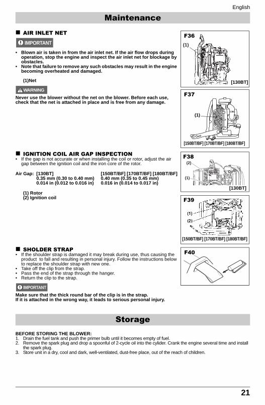
AIR INLET NET
IMPORTANT
• Blown air is taken in from the air inlet net. If the air flow drops during operation, stop the engine and inspect the air inlet net for blockage by obstacles.
• Note that failure to remove any such obstacles may result in the engine becoming overheated and damaged.
(1)Net
WARNING
Never use the blower without the net on the blower. Before each use, check that the net is attached in place and is free from any damage.
IGNITION COIL AIR GAP INSPECTION• If the gap is not accurate or when installing the coil or rotor, adjust the air
gap between the ignition coil and the iron core of the rotor.
Air Gap: [130BT] [150BT/BF] [170BT/BF] [180BT/BF]0.35 mm (0.30 to 0.40 mm) 0.40 mm (0.35 to 0.45 mm)0.014 in (0.012 to 0.016 in) 0.016 in (0.014 to 0.017 in)
(1) Rotor(2) Ignition coil
SHOLDER STRAP• If the shoulder strap is damaged it may break during use, thus causing the
product to fall and resulting in personal injury. Follow the instructions below to replace the shoulder strap with new one.
• Take off the clip from the strap.• Pass the end of the strap through the hanger.• Return the clip to the strap.
IMPORTANT
Make sure that the thick round bar of the clip is in the strap.If it is attached in the wrong way, it leads to serious personal injury.
BEFORE STORING THE BLOWER:1. Drain the fuel tank and push the primer bulb until it becomes empty of fuel.2. Remove the spark plug and drop a spoonful of 2-cycle oil into the cylider. Crank the engine several time and install
the spark plug.3. Store unit in a dry, cool and dark, well-ventilated, dust-free place, out of the reach of children.
Storage
(1)
(1)
F37
F36
[130BT]
[150BT/BF] [170BT/BF] [180BT/BF]
(2)
(1)
F39
[150BT/BF] [170BT/BF] [180BT/BF]
F38
[130BT]
F40
Maintenance
130BT&180BT_US-65.fm Page 21 Friday, December 7, 2007 1:05 PM

22
130BT&180BT_US-65.fm Page 22 Friday, December 7, 2007 1:05 PM