Embed Size (px)
Citation preview

10/14/2016
8:0
4:1
0
AM
RE
VISIO
N
NO.
SHEET
NO.
INDEXDESCRIPTION:
REVISION
LAST
of DESIGN STANDARDS
FY 2017-18
SIGNWARNING
SIGNWARNING
SIGNWARNING
ROADSIDE FLASHING BEACON ASSEMBLY
11/01/16 1 8 11862
GENERAL NOTES:
11. Orient solar panel to face South for optimal exposure to sunlight.
or rubber grommet to protect conductors.
10. When wire entry holes are drilled in the sign column, use a bushing
column in accordance with manufacturer’s recommendations.9. Install the connection of controller cabinet and solar panel to the
in the frangible transformer base.
single pole non-fused watertight breakaway electrical connectors
8. For beacon assemblies connected to conventional power, provide
slab dimensions may be adjusted as shown in the plans.
dimension is 4'-0" by 4'-0". In urban areas where space is limited
7. Install a concrete slab around all pull boxes. The minimum slab
slopes 6:1 or greater. The minimum slab dimension is 4'-0" by 5'-0".
6. Install a concrete slab around all flashing beacon assemblies on
and transformer bases.
5. Meet the requirements of Specifications 646 for aluminum poles
and post unless the aluminum post is fully seated into base.
transformer bases, engage all threads on the transformer base
4. When aluminum column (post) are installed with a frangible
with Index 17302.
3. Install sign column so that the height and offset are in accordance
11860 and Specifications 700.
2. Install sign panel, wind beam and columns in accordance with Index
as noted in the Plans.
Association Alloy 6061-T6 (ASTM B209, B221, B308 or B429), except
1. Use aluminum materials that meets the requirements of Aluminum
CONVENTIONAL POWERED BEACON
(With Transformer Base & Pull Box)
SOLAR POWERED BEACON
(With Slip Base) (With Transformer Base & Pull Box)
SOLAR POWERED BEACON WITH AUXILIARY POLE

10/14/2016
8:0
4:1
3
AM
RE
VISIO
N
NO.
SHEET
NO.
INDEXDESCRIPTION:
REVISION
LAST
of DESIGN STANDARDS
FY 2017-18
SIGNWARNING
Pull Box
12" Yellow Flashing Beacon
Beacon Controller
Sign Panel (48" x 48")
Beacon Controller
12" Yellow Flashing Beacon
1'-
0"
Nominal 4" (Sch. 40) Aluminum
See Index 17302
(See POLE WIRING AND FOOTING DETAIL)Transformer Base And Foundation
4'-
0"
2'-0" Dia.
Pull BoxGround Wire#6 TW Green
To Power Service Point
Crushed Stone For Drainage.12" Bed Of Pearock Or
(Typical)Size As Shown In Plans. Conductors And Conduit Conduit. Circuit In Schedule 40 PVC Circuit Conductors
connection (At all pull boxes)clad with approved ground5#8" diameter 20' long copperU.L. approved Ground Rod
FittingsReliefStrain
Ground Wire#6 TW Green
Anchor Bolts
" X 18"4
3
Concrete Apron (Typ.)
Footin
g
Depth
Transformer Base
Nominal 4" (Sch. 40) Aluminum Breakaway Electrical Connectors
Strain Relief Fitting
Finished Grade
ROADSIDE FLASHING BEACON ASSEMBLY
11/01/16 2 8 11862
FRONT VIEW SIDE VIEW
CONVENTIONAL POWERED WARNING SIGN DETAILS
POLE WIRING AND FOOTING DETAIL

10/14/2016
8:0
4:1
5
AM
RE
VISIO
N
NO.
SHEET
NO.
INDEXDESCRIPTION:
REVISION
LAST
of DESIGN STANDARDS
FY 2017-18
Wind Speed
110
130
150
110
130
150
STANDARD WARNING SIGN COLUMN SIZE
Sign Height
7'
7'
7'
8.5'
8.5'
8.5'
Column Size
4"
4.5"
5"
4.5"
5"
6"
Footing Depth
4'
4'
4.5'
4'
4.5'
5'
NOTES:
SIGNWARNING
12" Yellow Flashing Beacon
Beacon Controller
Sign Panel (48" x 48")
12" Yellow Flashing Beacon
Nominal 4" (Sch. 40) Aluminum
Beacon Controller
Solar Battery Compartment
Solar Battery Compartment
Solar Panel
1'-
0"
See Index 17302
9'-
6"
Control
Unit
And Battery Co
mpartm
ent
Minim
um Cle
arance For Controler,
Beacon
Solar Panel
Slip Base
FOOTING DETAIL)(See SLIP BASE ANDFoundation
TABLE 1
one beacon is required, install upper beacon.
3. Details show a typical warning sign with two flashing beacon heads. When only
2. Use beacon and beacon controllers that are listed on the Approved Products List (APL).
1. Install the sign column slip base in accordance with Index 11860.
Finished Grade
4"
Max.
3"
Min. Aluminum Stub
2'-0" Dia.
Base Plate Assembly
Sleeve, Stub and
Nominal 4" (Sch. 40) Aluminum
Footin
g
Depth
See Table For
ROADSIDE FLASHING BEACON ASSEMBLY
11/01/16 3 8 11862
FRONT VIEW SIDE VIEW
SOLAR POWERED WARNING SIGN DETAILS
SLIP BASE AND FOOTING DETAIL

10/14/2016
8:0
4:1
7
AM
RE
VISIO
N
NO.
SHEET
NO.
INDEXDESCRIPTION:
REVISION
LAST
of DESIGN STANDARDS
FY 2017-18
SIGNWARNING
Pull Box
12" Yellow Flashing Beacon
Sign Panel (48" x 48")
Nominal 4" (Sch. 40) Aluminum
NOTES:
BatteriesControl Unit And Controller, Solar Cabinet For Beacon
1'-
0"
Solar Panel
5'-
0"
Aluminum(Sch. 40) Nominal 4"
Solar Panel
(See Sheet 2 For Details)Transformer Base And Foundation
See Index 17302
electronic warning sign with flashing beacon.
4. Payment for the separate pole, foundation, conduit and wiring are included in the cost of the
3. Install the auxiliary pole so that the height is the same as the column for the beacon assembly.
2. Install the auxiliary pole as close to the right of way as possible.
beacon assemblies with solar panels, controllers and batteries weighing more than 170 lbs.
1. Install a separate pole for mounting the solar panel, controller and batteries for all flashing
Pull Box
7'-0"
2'-0"1'-0"
5'-
0"
2'-0" 1'-1" 11"
2'-
0"
Pull Box
Column Foundation
(See Note #6, Sheet 1)Concrete Slab
(See Note #6, Sheet 1)Concrete Slab
Finished Grade
Nominal 4" (Sch. 40) Aluminum
Column Foundation
(See Sheet 2 For Details)Transformer Base And Foundation
ROADSIDE FLASHING BEACON ASSEMBLY
11/01/16 4 8 11862
SIDE VIEW
BEACON
FRONT VIEW
POLE AND CONCRETE SLAB DETAIL
SOLAR POWERED BEACON WITH AUXILIARY
FRONT VIEW
AUXILIARY POLE
PLAN VIEW
ELEVATION VIEW
FOR POLES ON SLOPES
CONCRETE SLAB DETAIL
10/14/2016
8:0
4:1
9
AM
RE
VISIO
N
NO.
SHEET
NO.
INDEXDESCRIPTION:
REVISION
LAST
of DESIGN STANDARDS
FY 2017-18
7'-
0" LIGHTS
WARNING
TURN ON
BUTTON TO
PUSH
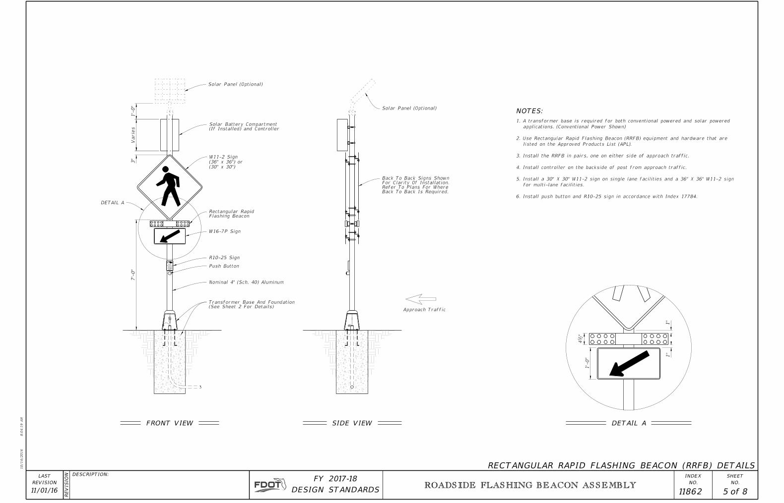
Solar Panel (Optional)
Flashing BeaconRectangular Rapid
W16-7P Sign
R10-25 Sign
Push Button
Nominal 4" (Sch. 40) Aluminum
Back To Back Is Required.Refer To Plans For Where For Clarity Of Installation. Back To Back Signs Shown
Solar Panel (Optional)NOTES:
DETAIL A
(30" x 30")
(36" x 36") or
W11-2 Sign
3"
1'-
0"
Varie
s (If Installed) and ControllerSolar Battery Compartment
6. Install push button and R10-25 sign in accordance with Index 17784.
for multi-lane facilities.
5. Install a 30" X 30" W11-2 sign on single lane facilities and a 36" X 36" W11-2 sign
4. Install controller on the backside of post from approach traffic.
3. Install the RRFB in pairs, one on either side of approach traffic.
listed on the Approved Products List (APL).
2. Use Rectangular Rapid Flashing Beacon (RRFB) equipment and hardware that are
applications. (Conventional Power Shown)
1. A transformer base is required for both conventional powered and solar powered
(See Sheet 2 For Details)Transformer Base And Foundation
"2
14
1'-
0"
1"
1"
ROADSIDE FLASHING BEACON ASSEMBLY
11/01/16 5 8 11862
Approach Traffic
FRONT VIEW SIDE VIEW
RECTANGULAR RAPID FLASHING BEACON (RRFB) DETAILS
DETAIL A

10/14/2016
8:0
4:2
1
AM
RE
VISIO
N
NO.
SHEET
NO.
INDEXDESCRIPTION:
REVISION
LAST
of DESIGN STANDARDS
FY 2017-18
7'-
0"
Solar Panel (Optional)
Nominal 4" (Sch. 40) Aluminum
Solar Panel (Optional)NOTES:
LIMIT
SPEED
SCHOOL
FLASHING
WHEN
20
Solar Battery Compartment (Optional)
Beacon Controller
12" Yellow Flashing Beacon
(Optional)Compartment Solar Battery
S5-1 (24" x 48") Sign
12" Yellow Flashing Beacon
1'-
0"
1'-
0"
1'-
0"
Min.
one beacon is required, install upper beacon.
3. Details show a typical school zone sign with two flashing beacon heads. When only
2. Use beacons and beacon controllers that are on the Approved Products List (APL).
applications. (Conventional Power Shown)
1. A transformer base is required for both conventional powered and solar powered
(See Sheet 2 For Details)Transformer Base And Foundation
ROADSIDE FLASHING BEACON ASSEMBLY
11/01/16 6 8 11862
FRONT VIEW SIDE VIEW
SCHOOL REGULATORY SIGN DETAILS
10/14/2016
8:0
4:2
3
AM
RE
VISIO
N
NO.
SHEET
NO.
INDEXDESCRIPTION:
REVISION
LAST
of DESIGN STANDARDS
FY 2017-18
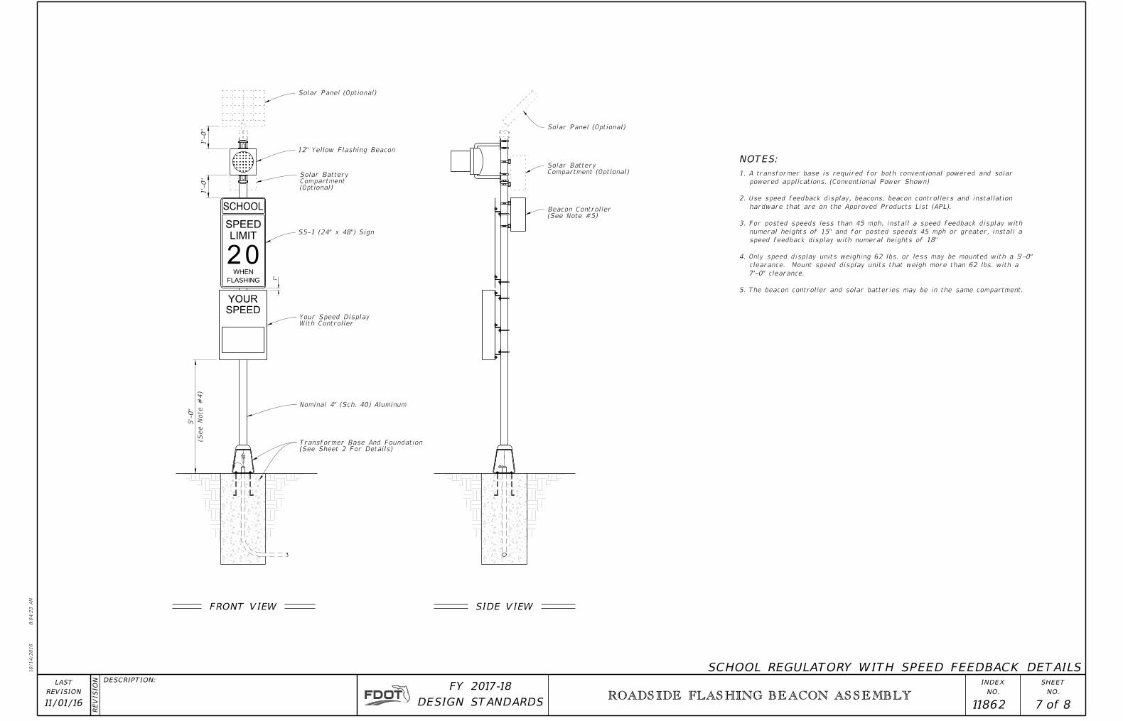
5'-
0"
Solar Panel (Optional)
Nominal 4" (Sch. 40) Aluminum
Solar Panel (Optional)
NOTES:
LIMIT
SPEED
SCHOOL
FLASHING
WHEN
SPEED
YOUR
20
(Optional)CompartmentSolar Battery
Compartment (Optional)Solar Battery
S5-1 (24" x 48") Sign
With ControllerYour Speed Display
(See
Note #
4)
1'-
0"
1'-
0"
1"
12" Yellow Flashing Beacon
(See Sheet 2 For Details)Transformer Base And Foundation
(See Note #5)Beacon Controller
5. The beacon controller and solar batteries may be in the same compartment.
7'-0" clearance.
clearance. Mount speed display units that weigh more than 62 lbs. with a
4. Only speed display units weighing 62 lbs. or less may be mounted with a 5'-0"
speed feedback display with numeral heights of 18"
numeral heights of 15" and for posted speeds 45 mph or greater, install a
3. For posted speeds less than 45 mph, install a speed feedback display with
hardware that are on the Approved Products List (APL).
2. Use speed feedback display, beacons, beacon controllers and installation
powered applications. (Conventional Power Shown)
1. A transformer base is required for both conventional powered and solar
ROADSIDE FLASHING BEACON ASSEMBLY
11/01/16 7 8 11862
FRONT VIEW SIDE VIEW
SCHOOL REGULATORY WITH SPEED FEEDBACK DETAILS

10/14/2016
8:0
4:2
6
AM
RE
VISIO
N
NO.
SHEET
NO.
INDEXDESCRIPTION:
REVISION
LAST
of DESIGN STANDARDS
FY 2017-18
5'-
0"
Solar Panel (Optional)
Nominal 4" (Sch. 40) Aluminum
Solar Panel (Optional)NOTES:
(Optional)CompartmentSolar Battery
Compartment (Optional)Solar Battery
R2-1 (24" x 30") Sign
(See
Note #
4)
SPEED
YOUR
LIMIT
SPEED
XX
Your Speed Display
12" Yellow Flashing Beacon
1'-
0"
1'-
0"
1"
5. The beacon controller and solar batteries may be in the same compartment.
7'-0" clearance.
clearance. Mount speed display units that weigh more than 62 lbs. with a
4. Only speed display units weighing 62 lbs. or less may be mounted with a 5'-0"
speed feedback display with numeral heights of 18"
numeral heights of 15" and for posted speeds 45 mph or greater, install a
3. For posted speeds less than 45 mph, install a speed feedback display with
hardware that are on the Approved Products List (APL).
2. Use speed feedback display, beacons, beacon controllers and installation
powered applications. (Conventional Power Shown)
1. A transformer base is required for both conventional powered and solar
(See Note #5)Beacon Controller
(See Sheet 2 For Details)Transformer Base And Foundation
ROADSIDE FLASHING BEACON ASSEMBLY
11/01/16 8 8 11862
FRONT VIEW SIDE VIEW
REGULATORY SIGN WITH SPEED FEEDBACK DETAILS