Embed Size (px)
Citation preview
INSTALLATION, OPERATING INSTRUCTION MANUAL AND
PARTS LIST FOR MODEL CT-55 & CT-75
CURTIS-TOLEDO, INC.
1905 Kienlen Ave. , St. Louis, Missouri 63133 ph: (800) 925-5431 fax: 314-381-1439
website: www.curtistoledo.com email: [email protected]
CAP410 DECEMBER, 2007
REV. F
PERSONAL INJURY AND/OR EQUIPMENT DAMAGE WILL RESULT FROM FAILURE TO PAY ATTENTION TO THE VITAL SAFETY INFORMATION AND INSTRUCTIONS IN THIS MANUAL. CAREFULLY READ, UNDERSTAND AND RETAIN ALL SAFETY INFORMATION AND INSTRUCTIONS BEFORE OPERATING THIS COMPRESSOR.
IMPORTANT Make a permanent record of the Model and Serial number of your machine here. You will save time and expense by including this reference identification on
replacement part orders.
WARNING Before installing and operating this
compressor, read and understand the safety precautions contained in LV-474
supplement to CAP-403.
SERIAL NO.
REFER TO MODEL & SERIAL NUMBER.READ INSTAL. & OPERATION INSTR.DO NOT OPERATE LOWER THAN 800R.P.M. OR ABOVE MAX. AS STIPULATEDBY PERFORMANCE DATA SHEET.
MODEL NO.
QAB-826

CT SERIES CAP 410
TABLE OF CONTENTS
TITLE PAGE INSTALLATION & ELECTRICAL REQUIREMENTS…………………………………… 1 LIMITED SAFETY PRECAUTIONS (Also see supplement LV-474)………………….. 2 START UP PROCEDURES……………………………………………………………….. 3 & 4 REBUILD KITS……………………………………………………………………………… 5 ASSEMBLY DRAWING, VERTICAL, 5HP – MODEL 555VT6………………………… 6 PARTS LIST – 5HP, MODEL 555VT6-A2 & 555VT8-A21...…………………………… 7 ASSEMBLY DRAWING, VERTICAL, 5HP – MODEL 555VT8………………………… 8 PARTS LIST – 5HP, MODEL 555VT8-A2, 555VT8-A9, 555VT8-A3, 555VT8-A4 & 555VT8-A8……………………………………………………… 9 ASSEMBLY DRAWING, VERTICAL, 7 1/2HP – MODEL 755VT8…………………….. 10 PARTS LIST – 7 1/2HP, MODEL 755VT8-A2, 755VT8-A9, 755VT8-A3, 755VT8-A4, 755VT8-A8……………………………………….. 11 ASSEMBLY DRAWING, VERTICAL, 7 1/2HP – MODEL 775VT8…………………….. 12 PARTS LIST – 7 1/2HP, MODEL 775VT8-A2, 775VT8-A3, 775VT8-A4, 775VT8-A8, 775VT8-A9……………...…………….. 13 ASSEMBLY DRAWING, VERTICAL, 10HP – MODEL 1075VT8…………….………...PARTS LIST - 10HP, MODEL 1075VT8-A2, 1075VT8-A3, 1075VT8-A4 1075VT8-A8, 1075VT8-A9 …………………………………...ASSEMBLY DRAWING, HORIZONTAL, 7 1/2HP – MODEL 775HT12……………….
14 15
16 17
18 19
PARTS LIST – 7 1/2HP, MODEL 775HT12-A2, 775HT12-A3, 775HT12-A4, 775HT12-A8, 775HT12-A9……………………………………….ASSEMBLY DRAWING, HORIZONTAL, 10HP – MODEL 1075HT12…………….…..PARTS LIST – 10HP, MODEL 1075HT12-A2, 1075HT12-A3, 1075HT12-A4, 1075HT12-A8, 1075HT12-A9……………………………………. ASSEMBLY DRAWING, HORIZONTAL, 13HP – HONDA……………………………... 20 PARTS LIST – 13HP, MODEL 1375GT3-HE, 1375GT6-HE…………………………… 21 ASSEMBLY DRAWING, HORIZONTAL, 13HP – KOHLER……………………………. 22 PARTS LIST – 13HP, MODEL 1375GT3-KC, 1375GT6-KC…………………………… 23 BOLT TORQUES & COMPRESSOR PUMP-UP TIMES…………………………….…. 24 TROUBLESHOOTING……………………………………………………………………… 25 DRYERS AND FILTERS…………………………………………………………………… 26 WIRING PROCEDURES - 3 PHASE FACTORY MOUNTED MOTOR STARTER….. 27 WIRING PROCEDURES - 3 PHASE FIELD INSTALLATION STARTER WIRING.… 28 WIRING PROCEDURES - 1 PHASE FACTORY MOUNTED STARTER……………. 29 WIRING PROCEDURES - 1 PHASE FIELD INSTALLATION STARTER………….… 30 WIRING PROCEDURES - PRESSURE SWITCH (WITH MAGNETIC STARTER).… 31 WIRING PROCEDURES - PRESSURE SWITCH, MODEL 555VT6-A2 & 555VT8-A21 (WITHOUT MAGNETIC STARTER)…….…
32

CT SERIES CAP 410
INSTALLATION
CONGRATULATIONS on your new CT Series Compressor. Please examine the compressor for shipping damage(s) and if any are found report it immediately to the carrier. Select a clean dry location with a rigid floor strong enough to support the compressor. If the compressor is to be located in an area where vibration is critical, properly engineered vibration mounts and flexible piping should be used. Remove the skid. NOTE: The compressor should never be operated on the shipping skid. Level the compressor so it can be bolted down securely. Before tightening the bolts, check to see that all four feet are resting on the foundation. Shim as necessary to eliminate stress on the receiver or base when the bolts are tightened. We suggest using a level for proper alignment. Maximum ambient temperature in which the compressor and motor should be operated is 104°F. Therefore, adequate ventilation must be provided.
The suction openings of the compressor are equipped with a combination air filter-muffler to protect the compressor from normal dust and other harmful substances. If the air around the compressor is excessively hot, dusty, humid or contaminated with foreign gases (such as ammonia or acid fumes) move the filter-muffler to a remote point where the air is clean, cool and dry. Run a pipe to the compressor suction opening. If the run is over 50 feet in length, use a larger pipe to avoid excessive pressure drop. In order to fit the filter to the compressor, bush down the connections. Be sure piping and fittings are clean and free from dirt and chips. If the filter is installed outside, check to insure that it is located above the normal outside dust level, and the filter element is protected against rain or ice.
ELECTRICAL REQUIREMENTS The electrical installation of this unit is required to be performed by a qualified electrician and must be in accordance with the latest edition of the National Electrical Code (N.E.C.), NFPA 70, O.S.H.A. Code including all local and state codes. Failure to comply by the national, state and local codes may result in physical harm and/or property damage. Do not under any circumstances by-pass any motor over current protection devices. NOTE: This unit must be grounded. Before installation, the electrical supply must be checked for adequate wire size and transformer capacity. Failure to install branch circuit protection with proper motor starters and overloads will void the motor manufacturers warranty. NOTE: Do not close the disconnect switch to start the compressor until the procedures outlined under “Startup Procedures” have been completed.
DANGER!
High voltage may cause personal injury or death, per O.S.H.A. regulations 1910.137, disconnect and lockout/tagout all electrical power supplies before opening the electrical enclosure or servicing.
WARNING!
Never assume a compressor is safe to work on just because it is not operating. It could restart at any time. Follow all safety precautions as outlined in this manual. All NEMA electrical enclosures and components must be in accordance with the surrounding environment of the installation.
PAGE 1

CT SERIES CAP 410
PAGE 2
LIMITED SAFETY PRECAUTIONS
(Also see supplement LV-474) The following safety precautions are recommended in the use of this compressor: 1. Furnished with a totally enclosed OSHA-
approved belt guard to cover the drive assembly. Where possible, place the flywheel toward the wall, and mount the unit a minimum distance of 2 feet from the wall for maintenance convenience.
2. Turn off & lock out the electrical disconnect switch before working on the unit to prevent the unit from starting unexpectedly
3. Release all air pressure from the system before working on the unit and red tag all electrical control switches, for safety precaution.
4. Do not by-pass motor over-current protection. 5. Do not change the setting or in any way affect
the operation of the safety valve. 6. Keep unit securely anchored so that movement
will not put a strain on piping, wiring, or air receiver. (DO NOT USE plastic pipe, rubber hose, or lead-tin soldered joints in any part of the compressed air system.)
WARNING: Read and understand supplement LV-474 before installing and operating the compressor.
CT SERIES CAP 410
PAGE 3
START-UP PROCEDURES OIL RECOMMENDATION Use Genuine CURTISLUBEPLUS Lubricants. Specially formulated for Curtis Reciprocating Air Compressors. Non-Detergent type with anti-foam, anti-rust and oxidation inhibitors. Recommended ISO68 RC-1000 Premium Reciprocating Compressor Lubricant, Part no. VO411-3, 12-quart case or VO411-2, 4 gallon case. Recommended ISO100 RC-1000A Premium Reciprocating Compressor Lubricant Part no. VO421-3, 12-quart case or VO421-2, 4 gallon case. CURTISLUBEPLUS Lubricants are available through your authorized Curtis distributor.
If the compressor is equipped with an automatic start-stop control (with pressure switch unloading), it is automatically unloaded upon starting, and will automatically load after attaining running speed. Close the disconnect switch and start the compressor. Observe the direction of rotation, which should be counterclockwise when viewed from the flywheel side of the compressor on all models. For single-phase units, the direction of rotation is determined by the motor nameplate instructions, and is adjusted at the factory. For three-phase units, if the rotation is incorrect, stop the unit and interchange any two of the three wires to the motor at the disconnect switch. This will reverse the direction of rotation of the motor and compressor.
PREVENTIVE MAINTENANCE TURN OFF POWER BEFORE SERVICING!!!
A good maintenance program will add years of service to your air compressor. The following is recommended as a minimum maintenance program. (DO NOT OPERATE WITHOUT BELT GUARD) LUBRICATION 1. For proper lubrication the compressor shall not be
operated below the minimum or above the maximum R. P.M. recommended for the various models.
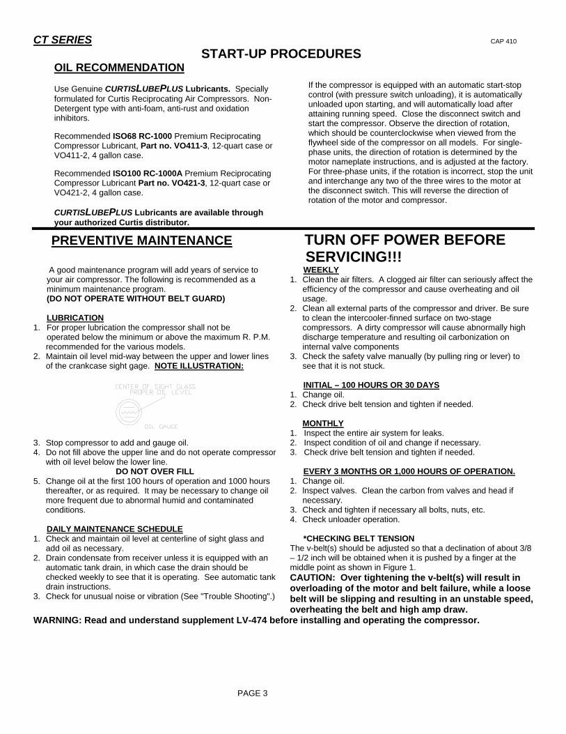
2. Maintain oil level mid-way between the upper and lower lines of the crankcase sight gage. NOTE ILLUSTRATION:
3. Stop compressor to add and gauge oil. 4. Do not fill above the upper line and do not operate compressor
with oil level below the lower line. DO NOT OVER FILL
5. Change oil at the first 100 hours of operation and 1000 hours thereafter, or as required. It may be necessary to change oil more frequent due to abnormal humid and contaminated conditions.
DAILY MAINTENANCE SCHEDULE 1. Check and maintain oil level at centerline of sight glass and
add oil as necessary. 2. Drain condensate from receiver unless it is equipped with an
automatic tank drain, in which case the drain should be checked weekly to see that it is operating. See automatic tank drain instructions.
3. Check for unusual noise or vibration (See "Trouble Shooting".)
WEEKLY 1. Clean the air filters. A clogged air filter can seriously affect the
efficiency of the compressor and cause overheating and oil usage.
2. Clean all external parts of the compressor and driver. Be sure to clean the intercooler-finned surface on two-stage compressors. A dirty compressor will cause abnormally high discharge temperature and resulting oil carbonization on internal valve components
3. Check the safety valve manually (by pulling ring or lever) to see that it is not stuck.
INITIAL – 100 HOURS OR 30 DAYS 1. Change oil. 2. Check drive belt tension and tighten if needed.
MONTHLY 1. Inspect the entire air system for leaks. 2. Inspect condition of oil and change if necessary. 3. Check drive belt tension and tighten if needed. EVERY 3 MONTHS OR 1,000 HOURS OF OPERATION. 1. Change oil. 2. lnspect valves. Clean the carbon from valves and head if
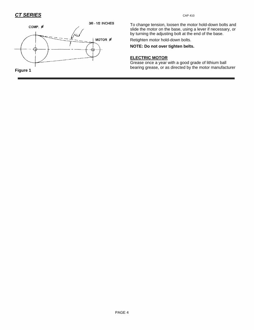
necessary. 3. Check and tighten if necessary all bolts, nuts, etc. 4. Check unloader operation. *CHECKING BELT TENSION The v-belt(s) should be adjusted so that a declination of about 3/8 – 1/2 inch will be obtained when it is pushed by a finger at the middle point as shown in Figure 1. CAUTION: Over tightening the v-belt(s) will result in overloading of the motor and belt failure, while a loose belt will be slipping and resulting in an unstable speed, overheating the belt and high amp draw.
WARNING: Read and understand supplement LV-474 before installing and operating the compressor.
CT SERIES CAP 410
PAGE 4
Figure 1
To change tension, loosen the motor hold-down bolts and slide the motor on the base, using a lever if necessary, or by turning the adjusting bolt at the end of the base. Retighten motor hold-down bolts. NOTE: Do not over tighten belts. ELECTRIC MOTOR Grease once a year with a good grade of lithium ball bearing grease, or as directed by the motor manufacturer
CT SERIES CAP 410
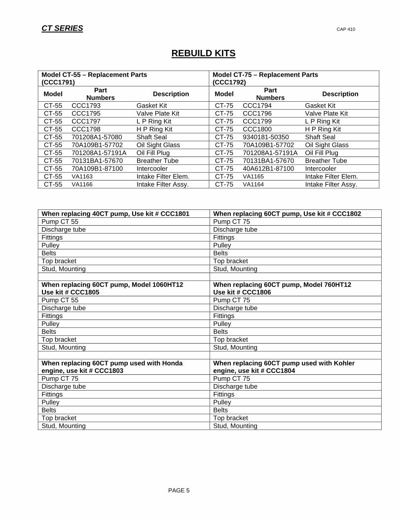
REBUILD KITS
Model CT-55 – Replacement Parts
(CCC1791) Model CT-75 – Replacement Parts (CCC1792)
Model Part Numbers Description Model Part
Numbers Description
CT-55 CCC1793 Gasket Kit CT-75 CCC1794 Gasket Kit CT-55 CCC1795 Valve Plate Kit CT-75 CCC1796 Valve Plate Kit CT-55 CCC1797 L P Ring Kit CT-75 CCC1799 L P Ring Kit CT-55 CCC1798 H P Ring Kit CT-75 CCC1800 H P Ring Kit CT-55 701208A1-57080 Shaft Seal CT-75 9340181-50350 Shaft Seal CT-55 70A109B1-57702 Oil Sight Glass CT-75 70A109B1-57702 Oil Sight Glass CT-55 701208A1-57191A Oil Fill Plug CT-75 701208A1-57191A Oil Fill Plug CT-55 70131BA1-57670 Breather Tube CT-75 70131BA1-57670 Breather Tube CT-55 70A109B1-87100 Intercooler CT-75 40A612B1-87100 Intercooler CT-55 VA1163 Intake Filter Elem. CT-75 VA1165 Intake Filter Elem. CT-55 VA1166 Intake Filter Assy. CT-75 VA1164 Intake Filter Assy.
When replacing 40CT pump, Use kit # CCC1801 When replacing 60CT pump, Use kit # CCC1802 Pump CT 55 Pump CT 75 Discharge tube Discharge tube Fittings Fittings Pulley Pulley Belts Belts Top bracket Top bracket Stud, Mounting Stud, Mounting When replacing 60CT pump, Model 1060HT12 Use kit # CCC1805
When replacing 60CT pump, Model 760HT12 Use kit # CCC1806
Pump CT 55 Pump CT 75 Discharge tube Discharge tube Fittings Fittings Pulley Pulley Belts Belts Top bracket Top bracket Stud, Mounting Stud, Mounting When replacing 60CT pump used with Honda engine, use kit # CCC1803
When replacing 60CT pump used with Kohler engine, use kit # CCC1804
Pump CT 75 Pump CT 75 Discharge tube Discharge tube Fittings Fittings Pulley Pulley Belts Belts Top bracket Top bracket Stud, Mounting Stud, Mounting
PAGE 5
CT SERIES CAP 410
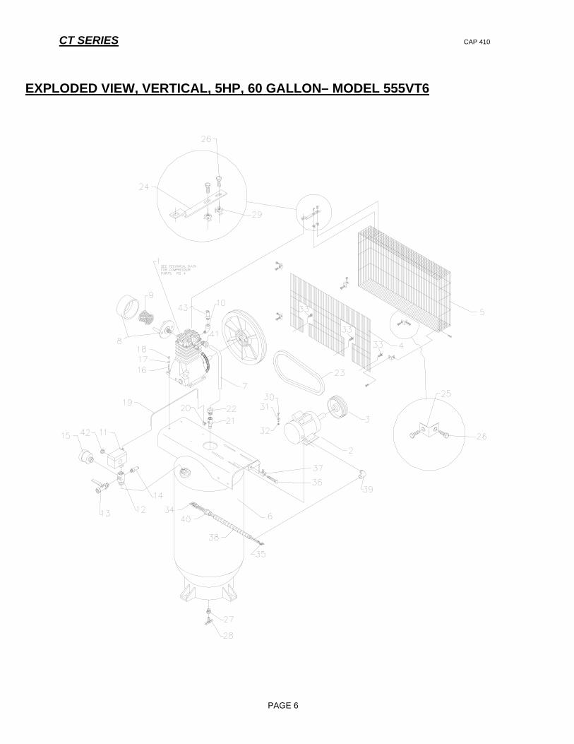
EXPLODED VIEW, VERTICAL, 5HP, 60 GALLON– MODEL 555VT6
PAGE 6
CT SERIES CAP 410
PAGE 7
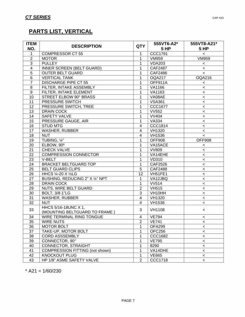
PARTS LIST, VERTICAL
ITEM NO. DESCRIPTION QTY 555VT6-A2*
5 HP 555VT8-A21*
5 HP 1 COMPRESSOR CT 55 1 CCC1791 < 2 MOTOR 1 VM959 VM959 3 PULLEY 1 VDA203 < 4 INNER SCREEN (BELT GUARD) 1 CAF2487 < 5 OUTER BELT GUARD 1 CAF2486 < 6 VERTICAL TANK 1 OQA217 OQA216 7 DISCHARGE PIPE CT 55 1 OFF911A < 8 FILTER, INTAKE ASSEMBLY 1 VA1166 < 9 FILTER, INTAKE ELEMENT 1 VA1163 < 10 STREET ELBOW 90° BRASS 1 VA08AE < 11 PRESSURE SWITCH 1 VSA361 < 12 PRESSURE SWITCH, TREE 1 CCC1677 < 13 DRAIN COCK 1 VV552 < 14 SAFETY VALVE 1 VV404 < 15 PRESSURE GAUGE, AIR 1 VA334 < 16 STUD MTG 4 CCC1814 < 17 WASHER, RUBBER 4 VH1320 < 18 NUT 4 VH1536 < 19 TUBING, ¼” 1 OFF908 OFF908 20 ELBOW, 90º 1 VA15ACE < 21 CHECK VALVE 1 VV809 < 22 COMPRESSION CONNECTOR 1 VA14EHE < 23 V-BELT 1 VD310 < 24 BRACKET BELTGUARD TOP 1 CAF2526 < 25 BELT GUARD CLIPS 5 CAF2488 < 26 HHCS ¼-20 X ½LG 12 VH51FE1 < 27 BUSHING, REDUCING 2” X ¼” NPT 1 VA12JBQ < 28 DRAIN COCK 1 VV514 < 29 NUTS, WIRE BELT GUARD 2 VH515 < 30 BOLT, 3/8-1”LG 3 VH10HH < 31 WASHER, RUBBER 4 VH1320 < 32 NUT 4 VH1536 <
33 HHCS 5/16-18UNC X 1, (MOUNTING BELTGUARD TO FRAME ) 3 VH1108 <
34 WIRE TERMINAL RING TONGUE 4 VE794 < 35 WIRE NUTS 2 VE741 < 36 MOTOR BOLT 1 OFA299 < 37 TAKE-UP, MOTOR BOLT 1 OFC256 < 38 CORD ASSSEMBLY 1 CCC1682 < 39 CONNECTOR, 90° 1 VE795 < 40 CONNECTOR, STRAIGHT 1 8290 < 41 COMPRESSION FITTING (not shown) 1 VA14DHE < 42 KNOCKOUT PLUG 1 VE665 < 43 HP 1/8” ASME SAFETY VALVE 2 CCC1718 <
* A21 = 1/60/230
CT SERIES CAP 410
PAGE 8
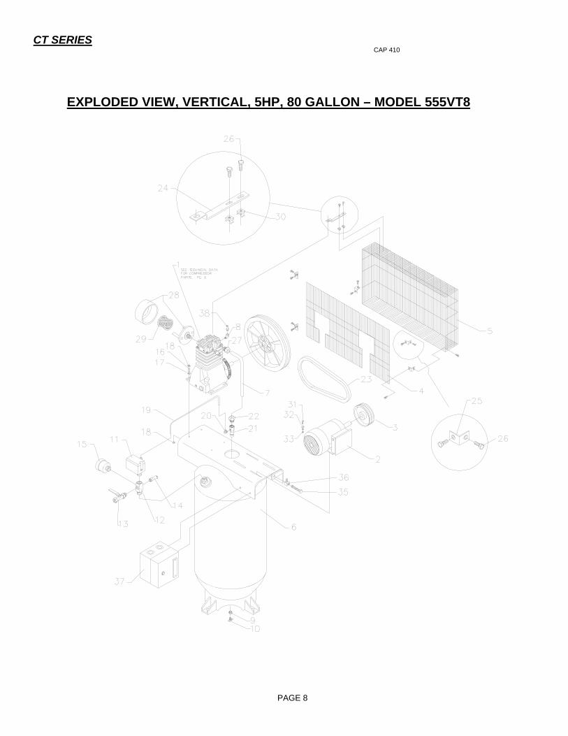
EXPLODED VIEW, VERTICAL, 5HP, 80 GALLON – MODEL 555VT8

CT SERIES CAP 410
PAGE 9
PARTS LIST, VERTICAL
ITEM NO. DESCRIPTION QTY 555VT8- 2* A
5 HP 555VT8- 9* A5 HP
555VT8-A3* 5 HP
555VT8-A4* 5 HP
555VT8-A8* 5 HP
1 COMPRESSOR CT 55 1 CCC1791 < < < < 2 MOTOR 1 VM957 VM960 VM908 VM908 VM961 3 PULLEY 1 VDB334 < < < < 4 INNER SCREEN (BELT GUARD) 1 CAF2487 < < < < 5 OUTER BELT GUARD 1 CAF2486 < < < < 6 VERTICAL TANK 1 OQA218 < < < < 7 DISCHARGE PIPE CT 55 1 OFF911A < < < < 9 BUSHING, 2” X ¼” 1 VA12JBQ < < < <
10 COCK, DRAIN 1 VV514 < < < < 11 PRESSURE SWITCH 1 VSA362 < < < < 12 PRESSURE SWITCH, TREE 1 CCC1677 < < < < 13 DRAIN COCK 1 VV552 < < < < 14 SAFETY VALVE 1 VV404 < < < < 15 PRESSURE GAUGE, AIR 1 VA334 < < < < 16 STUD, MOUNTING 4 CC1814 < < < < 17 WASHER, RUBBER 4 VH1320 < < < < 18 NUT, 5/16-18 4 VH1536 < < < < 19 TUBING, ¼” 1 OFF909 < < < < 20 ELBOW, 90º 1 VA15ACE < < < < 21 CHECK VALVE 1 VV809 < < < < 22 COMPRESSION CONNECTOR 1 VA14EHE < < < < 23 V-BELT 1 VD323 < < < < 24 BRACKET BELTGUARD TOP 1 CAF2526 < < < < 25 BELT GUARD CLIPS 5 CAF2488 < < < < 26 HHCS ¼-20 X 1/2LG 12 VH51FE1 < < < < 27 FITTING, COMPR, ½ X ¾ 1 VA14DHE < < < < 28 FILTER, INTAKE ASSEMBLY 1 VA1166 < < < < 29 FILTER, INTAKE ELEMENT 1 VA1163 < < < < 30 NUTS, WIRE BELT GUARD 2 VH515 < < < < 31 BOLT, CARRIAGE 3 VH10KH < < < < 32 WASHER, RUBBER 4 VH1321 < < < < 33 NUT 4 VH1537 < < < <
34 HHCS 5/16-18UNC X 1, MOUNTING BELTGUARD TO FRAME (NOT SHOWN) 3 VH1108 < < < <
35 MOTOR BOLT 1 OFA299 < < < < 36 TAKE-UP, MOTOR BOLT 1 OFC256 < < < < 37 STARTER KIT, (OPTIONAL) 1 CY60N CY60P CY60M CY60L CY60Q 38 HP 1/8” ASME SAFETY VALVE 2 CCC1718 < < < <
* A2 = 1/60/230 * A9 = 3/60/200 * A3 = 3/60/230 * A4 = 3/60/460 * A8 = 3/60/575

CT SERIES CAP 410
PAGE 10
EXPLODED VIEW, VERTICAL, 7 1/2HP, 80 GALLON – MODEL 755VT8

CT SERIES CAP 410
PAGE 11
PARTS LIST, VERTICAL
ITEM NO. DESCRIPTION QTY 755VT8-A2*
7 ½ HP 755VT8-A * 9
7 ½ HP 755VT8-A3*
7 ½ HP 755VT8-A4*
7 ½ HP 755VT8-A8*
7 ½ HP 1 COMPRESSOR CT 55 1 CCC1791 < < < < 2 MOTOR 1 VM1025 VM1028 VM1024 VM1024 VM1029 3 PULLEY 1 VDB339 < < < < 4 INNER SCREEN (BELT GUARD) 1 CAF2487 < < < < 5 OUTER BELT GUARD 1 CAF2486 < < < < 6 VERTICAL TANK 1 OQA218 < < < < 7 DISCHARGE PIPE CT 55 1 OFF911A < < < < 9 BUSHING, 2” X ¼” 1 VA12JBQ < < < <
10 COCK, DRAIN 1 VV514 < < < < 11 PRESSURE SWITCH 1 VSA360 < < < < 12 PRESSURE SWITCH, TREE 1 CCC1676 < < < < 13 DRAIN COCK 1 VV514 < < < < 14 SAFETY VALVE 1 VV404 < < < < 15 PRESSURE GAUGE, AIR 1 VA302 < < < < 16 STUD MTG, 5/16 –18 X 2-1/2”LG 4 CCC1814 < < < < 17 WASHER, RUBBER 4 VH1320 < < < < 18 NUT, 5/16-18 4 VH1536 < < < < 19 TUBING, ¼” 1 OFF909 < < < < 20 ELBOW, 90º 1 VA15ACE < < < < 21 CHECK VALVE 1 VV836 < < < < 22 COMPRESSION CONNECTOR 1 VA14EHE < < < < 23 V-BELT 1 VD323 < < < < 24 BRACKET BELTGUARD TOP 1 CAF2526 < < < < 25 BELT GUARD CLIPS 5 CAF2488 < < < < 26 HHCS ¼-20 X 1/2LG 12 VH51FE1 < < < < 27 FITTING, COMPR., ½ X 3/4 1 VA14DHE < < < < 28 FILTER, INTAKE ASSY 1 VA1166 < < < < 29 FILTER, INTAKE ELEMENT 1 VA1163 < < < < 30 NUTS, WIRE BELT GUARD 2 VH515 < < < < 31 BOLT, 3/8-1” LG. 3 VH10KH < < < < 32 WASHER, RUBBER 4 VH1321 < < < < 33 NUT 4 VH1537 < < < <
34 HHCS 5/16-18UNC X 1, MOUNTING BELTGUARD TO FRAME (NOT SHOWN) 3 VH12HH < < < <
35 MOTOR BOLT 1 OFA299 < < < < 36 TAKE-UP, MOTOR BOLT 1 OFC256 < < < < 37 STARTER KIT, (OPTIONAL) 1 CY60K CY60R CY60J CY60I CY60S 38 HP 1/8” ASME SAFETY VALVE 2 CCC1718 < < < <
* A2 = 1/60/230 * A9 = 3/60/200 * A3 = 3/60/230 * A4 = 3/60/460 * A8 = 3/60/575

CT SERIES CAP 410
PAGE 12
EXPLODED VIEW, VERTICAL, 7 1/2HP, 80 GALLON – MODEL 775VT8
CT SERIES CAP 410
PAGE 13
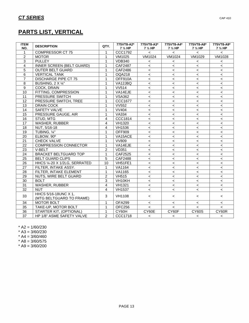
PARTS LIST, VERTICAL
* A2 = 1/60/230 * A3 = 3/60/230 * A4 = 3/60/460 * A8 = 3/60/575 * A9 = 3/60/200
ITEM NO. DESCRIPTION QTY. 775VT8-A2*
7 ½ HP 775VT8-A3*
7 ½ HP 775VT8-A4*
7 ½ HP 775VT8-A8*
7 ½ HP 775VT8-A9*
7 ½ HP 1 COMPRESSOR CT 75 1 CCC1792 < < < < 2 MOTOR 1 VM1025 VM1024 VM1024 VM1029 VM1028 3 PULLEY 1 VDB340 < < < < 4 INNER SCREEN (BELT GUARD) 1 CAF2487 < < < < 5 OUTER BELT GUARD 1 CAF2486 < < < < 6 VERTICAL TANK 1 OQA218 < < < < 7 DISCHARGE PIPE CT 75 1 OFF910A < < < < 8 BUSHING, 2 X ¼” 1 VA12JBQ < < < < 9 COCK, DRAIN 1 VV514 < < < < 10 FITTING, COMPRESSION 1 VA14EJE < < < < 11 PRESSURE SWITCH 1 VSA362 < < < < 12 PRESSURE SWITCH, TREE 1 CCC1677 < < < < 13 DRAIN COCK 1 VV552 < < < < 14 SAFETY VALVE 1 VV404 < < < < 15 PRESSURE GAUGE, AIR 1 VA334 < < < < 16 STUD, MTG 4 CCC1814 < < < < 17 WASHER, RUBBER 4 VH1320 < < < < 18 NUT, 5/16-18 4 VH1536 < < < < 19 TUBING, ¼” 1 OFF909 < < < < 20 ELBOW, 90º 1 VA15ACE < < < < 21 CHECK VALVE 1 VV809 < < < < 22 COMPRESSION CONNECTOR 1 VA14EJE < < < < 23 V-BELT 2 VD351 < < < < 24 BRACKET BELTGUARD TOP 1 CAF2525 < < < < 25 BELT GUARD CLIPS 5 CAF2488 < < < < 26 HHCS ¼-20 X 1/2LG, SERRATED 10 VH51FE1 < < < < 27 FILTER, INTAKE ASSY. 1 VA1164 < < < < 28 FILTER, INTAKE ELEMENT 1 VA1165 < < < < 29 NUTS, WIRE BELT GUARD 2 VH515 < < < < 30 BOLT 3 VH10KH < < < < 31 WASHER, RUBBER 4 VH1321 < < < < 32 NUT 4 VH1537 < < < <
33 HHCS 5/16-18UNC X 1, (MTG BELTGUARD TO FRAME) 3 VH1108 < < < <
34 MOTOR BOLT 1 OFA299 < < < < 35 TAKE-UP, MOTOR BOLT 1 OFC256 < < < < 36 STARTER KIT, (OPTIONAL) 1 CY60H CY60E CY60F CY60S CY60R 37 HP 1/8” ASME SAFETY VALVE 2 CCC1718 < < < <
CT SERIES CAP 410
PAGE 14
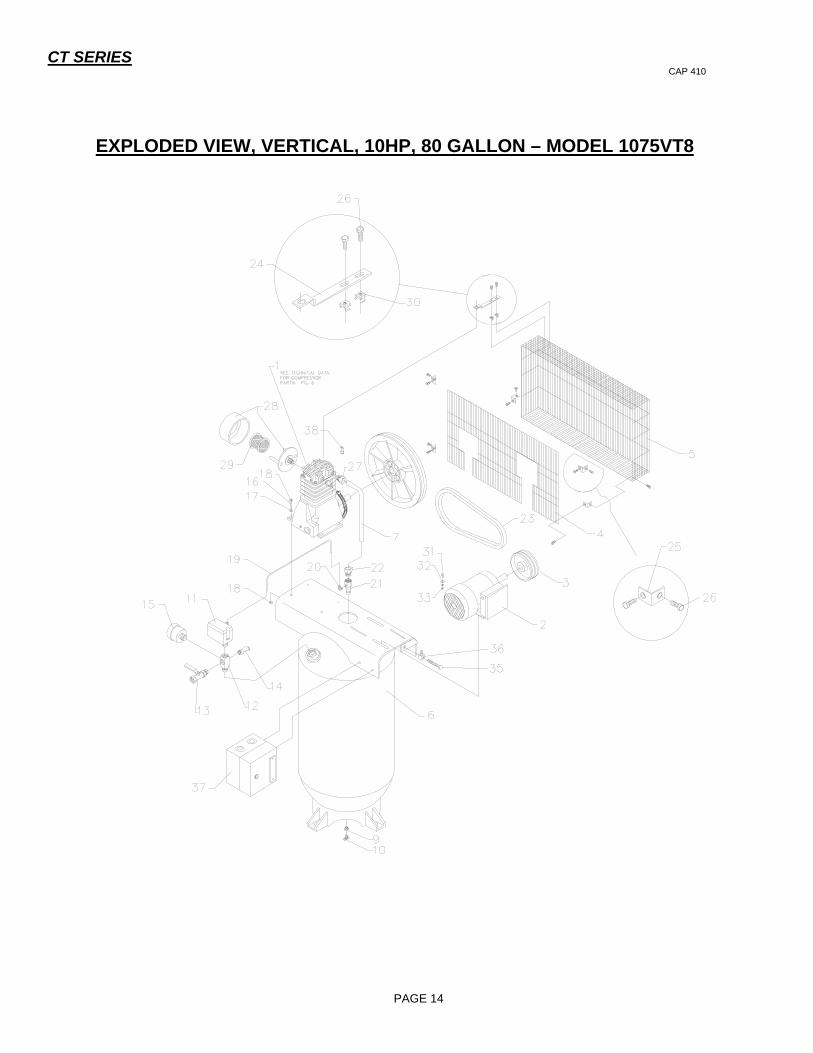
EXPLODED VIEW, VERTICAL, 10HP, 80 GALLON – MODEL 1075VT8
CT SERIES CAP 410
PAGE 15
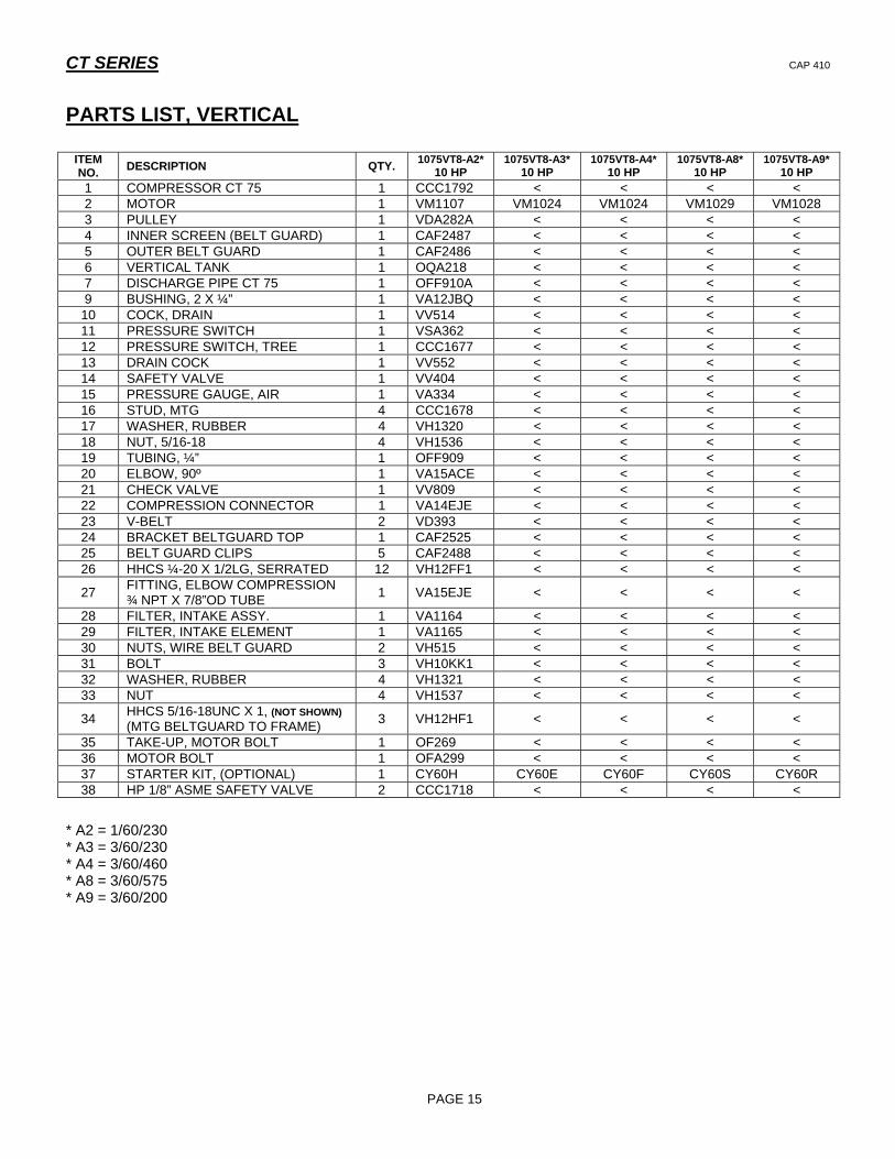
PARTS LIST, VERTICAL
* A2 = 1/60/230 * A3 = 3/60/230 * A4 = 3/60/460 * A8 = 3/60/575 * A9 = 3/60/200
ITEM NO. DESCRIPTION QTY. 1075VT8-A2*
10 HP 1075VT8-A3*
10 HP 1075VT8-A4*
10 HP 1075VT8-A8*
10 HP 1075VT8-A9*
10 HP 1 COMPRESSOR CT 75 1 CCC1792 < < < < 2 MOTOR 1 VM1107 VM1024 VM1024 VM1029 VM1028 3 PULLEY 1 VDA282A < < < < 4 INNER SCREEN (BELT GUARD) 1 CAF2487 < < < < 5 OUTER BELT GUARD 1 CAF2486 < < < < 6 VERTICAL TANK 1 OQA218 < < < < 7 DISCHARGE PIPE CT 75 1 OFF910A < < < < 9 BUSHING, 2 X ¼” 1 VA12JBQ < < < < 10 COCK, DRAIN 1 VV514 < < < < 11 PRESSURE SWITCH 1 VSA362 < < < < 12 PRESSURE SWITCH, TREE 1 CCC1677 < < < < 13 DRAIN COCK 1 VV552 < < < < 14 SAFETY VALVE 1 VV404 < < < < 15 PRESSURE GAUGE, AIR 1 VA334 < < < < 16 STUD, MTG 4 CCC1678 < < < < 17 WASHER, RUBBER 4 VH1320 < < < < 18 NUT, 5/16-18 4 VH1536 < < < < 19 TUBING, ¼” 1 OFF909 < < < < 20 ELBOW, 90º 1 VA15ACE < < < < 21 CHECK VALVE 1 VV809 < < < < 22 COMPRESSION CONNECTOR 1 VA14EJE < < < < 23 V-BELT 2 VD393 < < < < 24 BRACKET BELTGUARD TOP 1 CAF2525 < < < < 25 BELT GUARD CLIPS 5 CAF2488 < < < < 26 HHCS ¼-20 X 1/2LG, SERRATED 12 VH12FF1 < < < <
27 FITTING, ELBOW COMPRESSION ¾ NPT X 7/8”OD TUBE 1 VA15EJE < < < <
28 FILTER, INTAKE ASSY. 1 VA1164 < < < < 29 FILTER, INTAKE ELEMENT 1 VA1165 < < < < 30 NUTS, WIRE BELT GUARD 2 VH515 < < < < 31 BOLT 3 VH10KK1 < < < < 32 WASHER, RUBBER 4 VH1321 < < < < 33 NUT 4 VH1537 < < < <
34 HHCS 5/16-18UNC X 1, (NOT SHOWN) (MTG BELTGUARD TO FRAME) 3 VH12HF1 < < < <
35 TAKE-UP, MOTOR BOLT 1 OF269 < < < < 36 MOTOR BOLT 1 OFA299 < < < < 37 STARTER KIT, (OPTIONAL) 1 CY60H CY60E CY60F CY60S CY60R 38 HP 1/8” ASME SAFETY VALVE 2 CCC1718 < < < <

CT SERIES CAP 410
PAGE 16
EXPLODED VIEW, HORIZONTAL, 7 1/2HP, 120 GALLON – MODEL 775HT12
CT SERIES CAP 410
PAGE 17
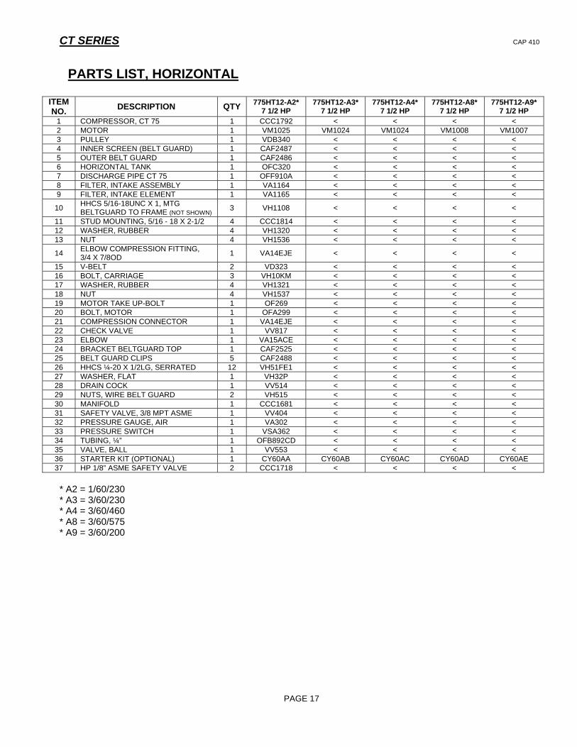
PARTS LIST, HORIZONTAL
ITEM NO. DESCRIPTION QTY 775HT12-A2*
7 1/2 HP 775HT12-A3*
7 1/2 HP 775HT12-A4*
7 1/2 HP 775HT12-A8*
7 1/2 HP 775HT12-A9*
7 1/2 HP 1 COMPRESSOR, CT 75 1 CCC1792 < < < < 2 MOTOR 1 VM1025 VM1024 VM1024 VM1008 VM1007 3 PULLEY 1 VDB340 < < < < 4 INNER SCREEN (BELT GUARD) 1 CAF2487 < < < < 5 OUTER BELT GUARD 1 CAF2486 < < < < 6 HORIZONTAL TANK 1 OFC320 < < < < 7 DISCHARGE PIPE CT 75 1 OFF910A < < < < 8 FILTER, INTAKE ASSEMBLY 1 VA1164 < < < < 9 FILTER, INTAKE ELEMENT 1 VA1165 < < < <
10 HHCS 5/16-18UNC X 1, MTG BELTGUARD TO FRAME (NOT SHOWN) 3 VH1108 < < < <
11 STUD MOUNTING, 5/16 - 18 X 2-1/2 4 CCC1814 < < < < 12 WASHER, RUBBER 4 VH1320 < < < < 13 NUT 4 VH1536 < < < <
14 ELBOW COMPRESSION FITTING, 3/4 X 7/8OD 1 VA14EJE < < < <
15 V-BELT 2 VD323 < < < < 16 BOLT, CARRIAGE 3 VH10KM < < < < 17 WASHER, RUBBER 4 VH1321 < < < < 18 NUT 4 VH1537 < < < < 19 MOTOR TAKE UP-BOLT 1 OF269 < < < < 20 BOLT, MOTOR 1 OFA299 < < < < 21 COMPRESSION CONNECTOR 1 VA14EJE < < < < 22 CHECK VALVE 1 VV817 < < < < 23 ELBOW 1 VA15ACE < < < < 24 BRACKET BELTGUARD TOP 1 CAF2525 < < < < 25 BELT GUARD CLIPS 5 CAF2488 < < < < 26 HHCS ¼-20 X 1/2LG, SERRATED 12 VH51FE1 < < < < 27 WASHER, FLAT 1 VH32P < < < < 28 DRAIN COCK 1 VV514 < < < < 29 NUTS, WIRE BELT GUARD 2 VH515 < < < < 30 MANIFOLD 1 CCC1681 < < < < 31 SAFETY VALVE, 3/8 MPT ASME 1 VV404 < < < < 32 PRESSURE GAUGE, AIR 1 VA302 < < < < 33 PRESSURE SWITCH 1 VSA362 < < < < 34 TUBING, ¼” 1 OFB892CD < < < < 35 VALVE, BALL 1 VV553 < < < < 36 STARTER KIT (OPTIONAL) 1 CY60AA CY60AB CY60AC CY60AD CY60AE 37 HP 1/8” ASME SAFETY VALVE 2 CCC1718 < < < < * A2 = 1/60/230 * A3 = 3/60/230 * A4 = 3/60/460 * A8 = 3/60/575 * A9 = 3/60/200

CT SERIES CAP 410
PAGE 18
EXPLODED VIEW, HORIZONTAL, 10HP, 120 GALLON –MODEL 1075HT12

CT SERIES CAP 410
PAGE 19
PARTS LIST, HORIZONTAL
ITEM NO. DESCRIPTION QTY 1075HT12-A3*
10 HP 1075HT12-A4*
10 HP 1075HT12-A8*
10 HP 1075HT12-A9*
10 HP 1 COMPRESSOR, CT 75 1 CCC1792 < < < 2 MOTOR 1 VM 1100 VM 1100 VM1127 VM1126 3 PULLEY 1 VDA282A < < < 4 INNER SCREEN (BELT GUARD) 1 CAF2487 < < < 5 OUTER BELT GUARD 1 CAF2486 < < < 6 HORIZONTAL TANK 1 OFC320 < < < 7 DISCHARGE PIPE CT75 1 OFF910A < < < 8 FILTER, INTAKE ASSEMBLY 1 VA1164 < < < 9 FILTER, INTAKE ELEMENT 1 VA1165 < < <
10 HHCS 5/16-18UNC X 1, MTGBELTGUARD TO FRAME 3 VH1108 < < <
11 STUD MOUNTING, 5/16 - 18 X 2-1/2 4 CCC1814 < < < 12 WASHER, RUBBER 4 VH1320 < < < 13 NUT 4 VH1536 < < <
14 ELBOW COMPRESSION FITTING, 3/4 X 7/8OD 1 VA14EJE < < <
15 V-BELT 2 VD393 < < < 16 BOLT, CARRIAGE 3 VH10KM < < < 17 WASHER, RUBBER 4 VH1321 < < < 18 NUT 4 VH1537 < < < 19 MOTOR TAKE UP-BOLT 1 OF269 < < < 20 BOLT, MOTOR 1 OFA299 < < < 21 COMPRESSION CONNECTOR 1 VA14EJE < < < 22 CHECK VALVE 1 VV817 < < < 23 ELBOW 1 VA15ACE < < < 24 BRACKET BELTGUARD TOP 1 CAF2525 < < < 25 BELT GUARD CLIPS 5 CAF2488 < < < 26 HHCS ¼-20 X 1/2LG, SERRATED 12 VH51FE1 < < < 28 DRAIN COCK 1 VV514 < < < 29 NUTS, WIRE BELT GUARD 2 VH515 < < < 30 MANIFOLD 1 CCC1681 < < < 31 SAFETY VALVE, 3/8 MPT ASME 1 VV404 < < < 32 PRESSURE GAUGE, AIR 1 VA302 < < < 33 PRESSURE SWITCH 1 VSA362 < < < 34 TUBING, ¼” 1 OFB892CD < < < 35 VALVE, BALL, ¾”MALE X ¾” FEMALE 1 VV553 < < < 36 STARTER KIT (OPTIONAL) 1 CY60D CY60 E CY60U CY60T 37 HP 1/8” ASME SAFETY VALVE 2 CCC1718 < < < * A3 = 3/60/230 * A4 = 3/60/460 * A8 = 3/60/575 * A9 = 3/60/200

CT SERIES CAP 410
PAGE 20
EXPLODED VIEW, HORIZONTAL, 13HP–HONDA

CT SERIES CAP 410
PAGE 21
PARTS LIST, HORIZONTAL, HONDA ENGINE
ITEM
NO. DESCRIPTION QTY
1375GT3-HE
13 HP 1375GT6-HE
13 HP
1 COMPRESSOR, CT 75 1 CCC1792 <
2 ENGINE, HONDA GAS 1 VN1036 <
3 PULLEY 1 VDB351 <
4 BELT GUARD 1 CAF2513P <
5 PAN, BELT GUARD 1 CAF2514P <
6 HORIZONTAL TANK 1 OFC247M OFC248L
7 DISCHARGE PIPE, CT75 1 OFF927 <
8 FILTER, INTAKE ASSEMBLY 1 VA1164 <
9 FILTER, INTAKE ELEMENT 1 VA1165 <
10 HHCS 5/16-18UNC X 1, MTG BELTGUARD TO FRAME 2 VH12HF <
11 WASHER, FLAT 3/4 4 VH32H <
12 WASHER, LOCK 5/16 2 VH35H <
13 NUT, 5/16 2 VH15H <
14 STUD MOUNTING, 5/16 - 18 X 2-1/2 4 CCC1814 <
15 WASHER, RUBBER 4 VH1320 <
16 NUT 4 VH1536 <
17 STRAIGHT CONNECTOR, COMPRESSION FITTING,
3/4 X 3/4OD 1 VA14EJE <
18 V-BELT 1 VD371 <
19 BOLT, CARRIAGE 3 VH10KM <
20 BOLT, MOTOR 1 OFC290 <
21 MOTOR TAKE UP-BOLT 1 OFC256 <
22 WASHER, FLAT 3/8 8 VH33K <
23 WASHER, LOCK 3/8 8 VH35K <
24 NUT, 3/8 8 VH15K <
25 COMPRESSION CONNECTOR 1 VA779 <
26 VALVE, DISCHARGE LINE UNLOADER 1 VV1009 <
27 CONNECTION COMPRESSION STRAIGHT 1 VA14EJE <
28 INSERT 2 VA1620 <
29 COPPER TUBING 1 OFD806 <
30 SLOW DOWN DEVICE 1 VN109 <
31 HHCS-3/8-16UNC X 1 1/4LG 4 VH12KK <
32 BRACKET, BELTGUARD TOP 1 CAF2535 <
33 HHCS, ¼-20 X ¾ LG 10 VH12FF <
34 WASHER, FLAT ¼ 10 VH32F <
35 WASHER, LOCK ¼ 10 VH35F1 <
36 NUT, HEX ¼-20 4 VH15F1 <
37 HP 1/8” ASME SAFETY VALVE 1 CCC1718 <
38 WASHER, STEEL CUT 1 VH32D <
39 VALVE, BALL 1 VV552 <
40 DRAIN, COCK 1 VV514 <
41 PLATE, ENGINE MOUNTING 1 CAF2334 <
42 BRACKET, BELTGUARD 2 CAE2284 <
43 MANIFOLD 1 CCC1695 <
44 SAFETY VALVE, 3/8 MPT ASME 1 VV404 <
45 PRESSURE GAUGE, AIR 1 VA302 <
46 SLEEVE, BRASS ¾” 1 VA778 <

CT SERIES CAP 410
PAGE 22
EXPLODED VIEW, HORIZONTAL, 13HP, KOHLER ENGINE

CT SERIES CAP 410
PAGE 23
PARTS LIST, HORIZONTAL, KOHLER ENGINE
ITEM NO. DESCRIPTION QTY 1375GT3-KC
13 HP 1375GT6-KC
13 HP 1 COMPRESSOR, CT 75 1 CCC1792 < 2 ENGINE, KOHLER GAS 1 VN1034 < 3 PULLEY 1 VDB351 < 4 BELT GUARD 1 CAF2337P < 5 PAN, BELT GUARD 1 CAB2295P < 6 HORIZONTAL TANK 1 OFC247P OFC248N 7 DISCHARGE PIPE, CT75 1 OFF928 < 8 FILTER, INTAKE ASSEMBLY 1 VA1164 < 9 FILTER, INTAKE ELEMENT 1 VA1165 <
10 HHCS 5/16-18UNC X 1, MTG BELTGUARD TO FRAME 2 VH12HF < 11 WASHER, FLAT 3/4 4 VH32H < 12 WASHER, LOCK 5/16 2 VH35H < 13 NUT, 5/16 2 VH15H < 14 STUD MOUNTING, 5/16 - 18 X 2-1/2 4 CCC1814 < 15 WASHER, RUBBER 4 VH1320 < 16 NUT 4 VH1536 <
17 STRAIGHT CONNECTOR, COMPRESSION FITTING ¾ X ¾ OD 1 VA14EJE <
18 V-BELT 1 VD371 < 19 BOLT, CARRIAGE 3 VH10KN < 20 BOLT, MOTOR 1 OFC290 < 21 MOTOR TAKE UP-BOLT 1 OF269 < 22 WASHER, FLAT 3/8 8 VH32K < 23 WASHER, LOCK 3/8 8 VH35K < 24 NUT, 3/8 8 VH15K < 25 COMPRESSION CONNECTOR 1 VA14EJE < 26 VALVE, DISCHARGE LINE UNLOADER 1 VV1009 < 27 CONNECTION COMPRESSION STRAIGHT 1 VA14ACE < 28 INSERT 2 VA1620 < 29 NYLON TUBING 1 VA1601 < 30 SLOW DOWN DEVICE 1 VN112 < 31 HHCS-3/8-16UNC X 1 1/4LG 4 VH12KK < 32 BRACKET, BELTGUARD TOP 1 CAF2534 < 33 HHCS, ¼-20 X ¾ LG 10 VH12FF < 34 WASHER, FLAT ¼ 10 VH32F < 35 WASHER, LOCK ¼ 10 VH35F1 < 36 NUT, HEX ¼-20 4 VH15F1 < 37 HP 1/8” ASME SAFETY VALVE 1 CCC1718 < 38 WASHER, STEEL CUT 1 VH32P < 39 VALVE, BALL 1 VV552 < 40 DRAIN, COCK 1 VV514 < 41 PLATE, ENGINE MOUNTING 1 CAF2334 < 42 BRACKET, BELTGUARD 2 CAE2286 < 43 MANIFOLD 1 CCC1695 < 44 SAFETY VALVE, 3/8 MPT ASME 1 VV404 < 45 PRESSURE GAUGE, AIR 1 VA302 < 46 SLEEVE-BRASS ¾” 1 VA778 <
CT SERIES CAP 410
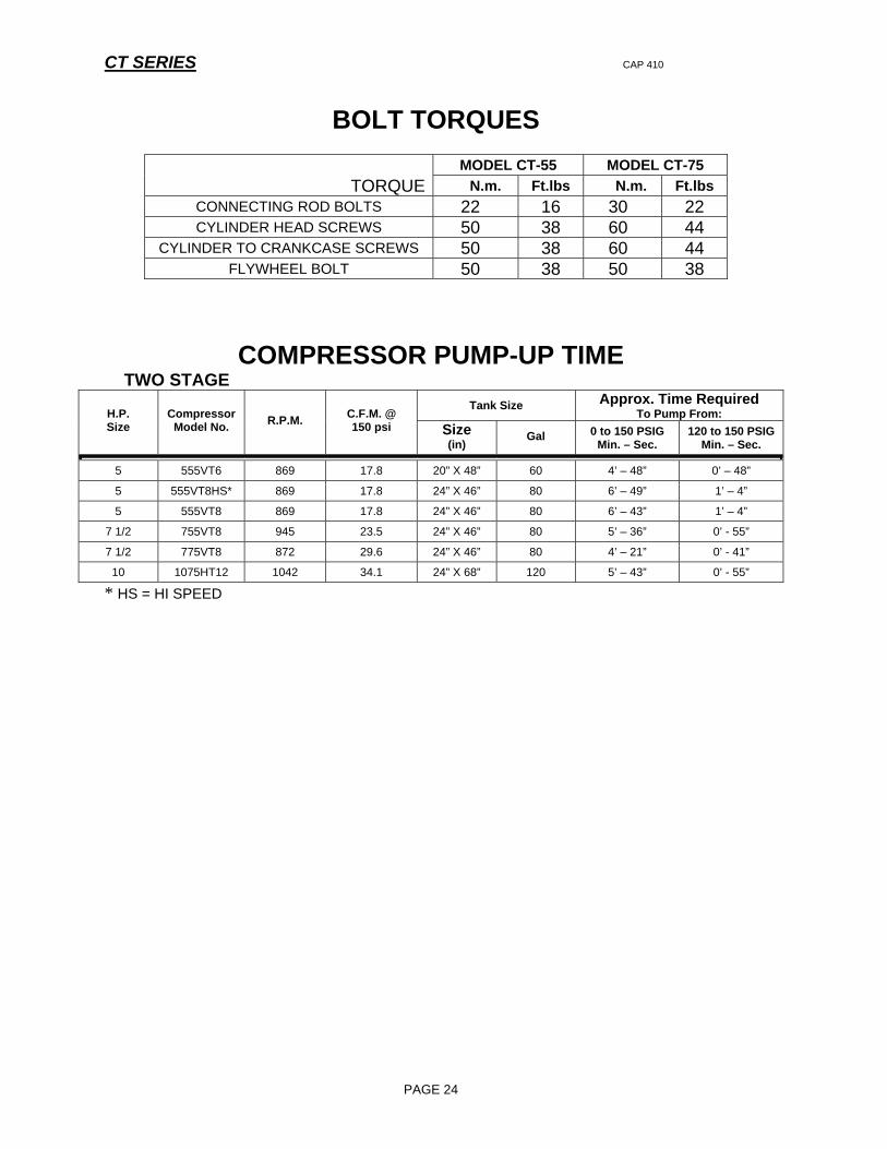
BOLT TORQUES
MODEL CT-55 MODEL CT-75 TORQUE N.m. Ft.lbs N.m. Ft.lbs
CONNECTING ROD BOLTS 22 16 30 22 CYLINDER HEAD SCREWS 50 38 60 44
CYLINDER TO CRANKCASE SCREWS 50 38 60 44 FLYWHEEL BOLT 50 38 50 38
COMPRESSOR PUMP-UP TIME TWO STAGE
Tank Size Approx. Time Required To Pump From: H.P.
Size Compressor
Model No. R.P.M. C.F.M. @ 150 psi Size
(in) Gal 0 to 150 PSIG
Min. – Sec. 120 to 150 PSIG
Min. – Sec.
5 555VT6 869 17.8 20” X 48” 60 4’ – 48” 0’ – 48”
5 555VT8HS* 869 17.8 24” X 46” 80 6’ – 49” 1’ – 4”
5 555VT8 869 17.8 24” X 46” 80 6’ – 43” 1’ – 4”
7 1/2 755VT8 945 23.5 24” X 46” 80 5’ – 36” 0’ - 55”
7 1/2 775VT8 872 29.6 24” X 46” 80 4’ – 21” 0’ - 41”
10 1075HT12 1042 34.1 24” X 68” 120 5’ – 43” 0’ - 55”
* HS = HI SPEED
PAGE 24
CT SERIES CAP 410
PAGE 25
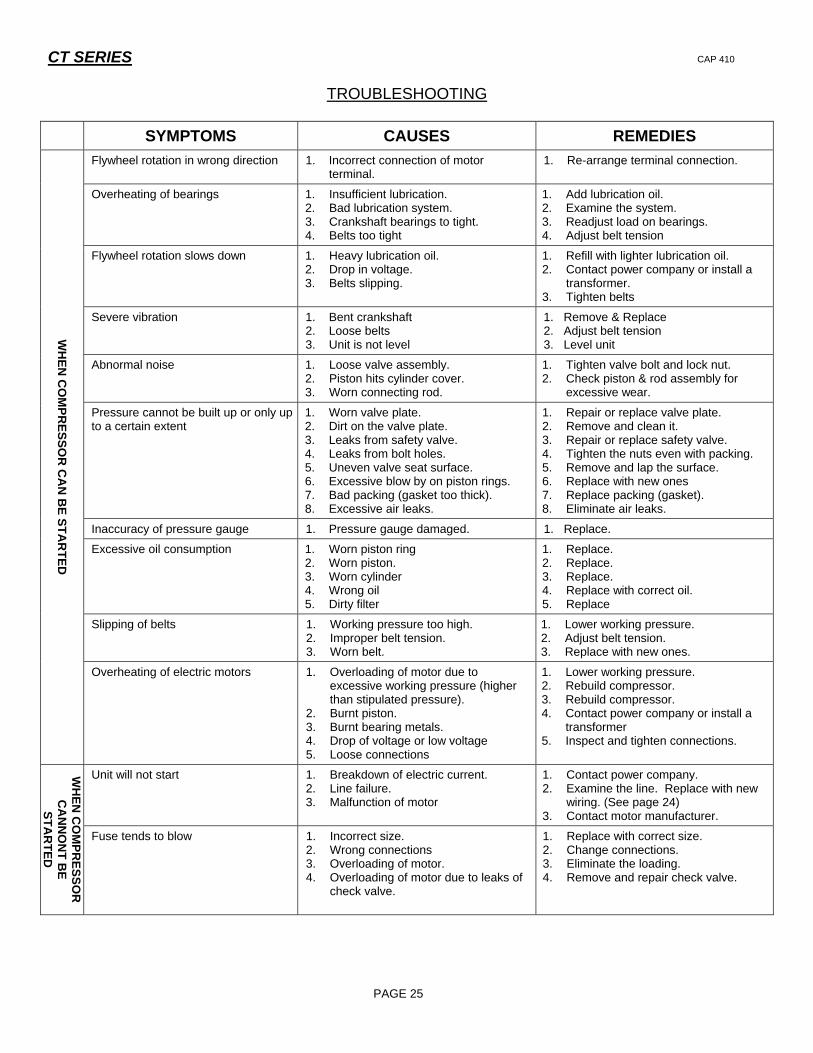
TROUBLESHOOTING
SYMPTOMS CAUSES REMEDIES
Flywheel rotation in wrong direction 1. Incorrect connection of motor terminal.
1. Re-arrange terminal connection.
Overheating of bearings
1. Insufficient lubrication. 2. Bad lubrication system. 3. Crankshaft bearings to tight. 4. Belts too tight
1. Add lubrication oil. 2. Examine the system. 3. Readjust load on bearings. 4. Adjust belt tension
Flywheel rotation slows down 1. Heavy lubrication oil. 2. Drop in voltage. 3. Belts slipping.
1. Refill with lighter lubrication oil. 2. Contact power company or install a
transformer. 3. Tighten belts
Severe vibration
1. Bent crankshaft 2. Loose belts 3. Unit is not level
1. Remove & Replace 2. Adjust belt tension 3. Level unit
Abnormal noise 1. Loose valve assembly. 2. Piston hits cylinder cover. 3. Worn connecting rod.
1. Tighten valve bolt and lock nut. 2. Check piston & rod assembly for
excessive wear.
Pressure cannot be built up or only up to a certain extent
1. Worn valve plate. 2. Dirt on the valve plate. 3. Leaks from safety valve. 4. Leaks from bolt holes. 5. Uneven valve seat surface. 6. Excessive blow by on piston rings. 7. Bad packing (gasket too thick). 8. Excessive air leaks.
1. Repair or replace valve plate. 2. Remove and clean it. 3. Repair or replace safety valve. 4. Tighten the nuts even with packing. 5. Remove and lap the surface. 6. Replace with new ones 7. Replace packing (gasket). 8. Eliminate air leaks.
Inaccuracy of pressure gauge 1. Pressure gauge damaged. 1. Replace.
Excessive oil consumption
1. Worn piston ring 2. Worn piston. 3. Worn cylinder 4. Wrong oil 5. Dirty filter
1. Replace. 2. Replace. 3. Replace. 4. Replace with correct oil. 5. Replace
Slipping of belts 1. Working pressure too high. 2. Improper belt tension. 3. Worn belt.
1. Lower working pressure. 2. Adjust belt tension. 3. Replace with new ones.
WH
EN C
OM
PRESSO
R C
AN
BE STA
RTED
Overheating of electric motors
1. Overloading of motor due to excessive working pressure (higher than stipulated pressure).
2. Burnt piston. 3. Burnt bearing metals. 4. Drop of voltage or low voltage 5. Loose connections
1. Lower working pressure. 2. Rebuild compressor. 3. Rebuild compressor. 4. Contact power company or install a
transformer 5. Inspect and tighten connections.
Unit will not start 1. Breakdown of electric current. 2. Line failure. 3. Malfunction of motor
1. Contact power company. 2. Examine the line. Replace with new
wiring. (See page 24) 3. Contact motor manufacturer.
WH
EN C
OM
PRESSO
R
CA
NN
ON
T BE
STAR
TED
Fuse tends to blow 1. Incorrect size. 2. Wrong connections 3. Overloading of motor. 4. Overloading of motor due to leaks of
check valve.
1. Replace with correct size. 2. Change connections. 3. Eliminate the loading. 4. Remove and repair check valve.
CT SERIES CAP 410
PAGE 26
RECOMMENDED STATEMENT ON DRYERS AND FILTERS Liquid water occurs naturally in air-lines as a result of compression. Moisture vapor in ambient air is concentrated when pressurized and condenses when cooled in downstream air piping. Compressed air dryers reduce water vapor concentration and prevent liquid water formation in compressed air lines. Dryers are necessary companion to air filters, aftercoolers, and automatic tank drains for improving the productivity of compressed air systems. Water and water vapor removal increases the efficiency of air operated equipment, reduces contamination and rusting, increases service life of pneumatic equipment and tools, prevents air line freeze ups, and reduces product rejects. The use of dryer’s filters is recommended when this moisture related problems are reported to our factory or distributor service departments. Troubleshooting guide Symptom: Liquid water present in compressed air-lines. Problem: Water vapor condensation from cooling and
compression occurs naturally Solution: Remove the water vapor from compressed air prior to
distribution through the air system. Check operation of after-cooler and moisture separator. Install a compressed air dryer sized for the flow and dryness level required.
(Note: filters may also be required to remove
particles, liquid oil aerosols, or for oil vapor removal. Change cartridges as recommended by filter manufacturer.)
Check all drain traps routinely to insure their proper operation.
Maintain them regularly.

CT SERIES CAP 403
WIRING PROCEDURES FOR 3 PHASE FACTORY MOUNTED MOTOR STARTER
CONNECT INCOMING POWER WIRES TO STARTER TERMINALS L1, L2 & L3.
THERMAL OVERLOADS (3)
TURN OFF POWER BEFORE SERVICING!!!
FACTORY MOUNTED MOTOR STARTERS ARE SUPPLIED WITH PRESSURE SWITCH AND MOTOR CONNECTIONS TO STARTER.
1. CONNECT INCOMING POWER WIRES TO STARTER TERMINALS L1, L2 AND L3.
2. COMPRESSOR FLYWHEEL ROTATION SHOULD BE COUNTERCLOCKWISE WHEN FACING FLYWHEEL.
3. IF COMPRESSOR FLYWHEEL ROTATION IS REVERSED, INTERCHANGE SERVICE WIRES TO STARTER TERMINALS L1 AND L2.
PAGE 27
CT SERIES CAP 410
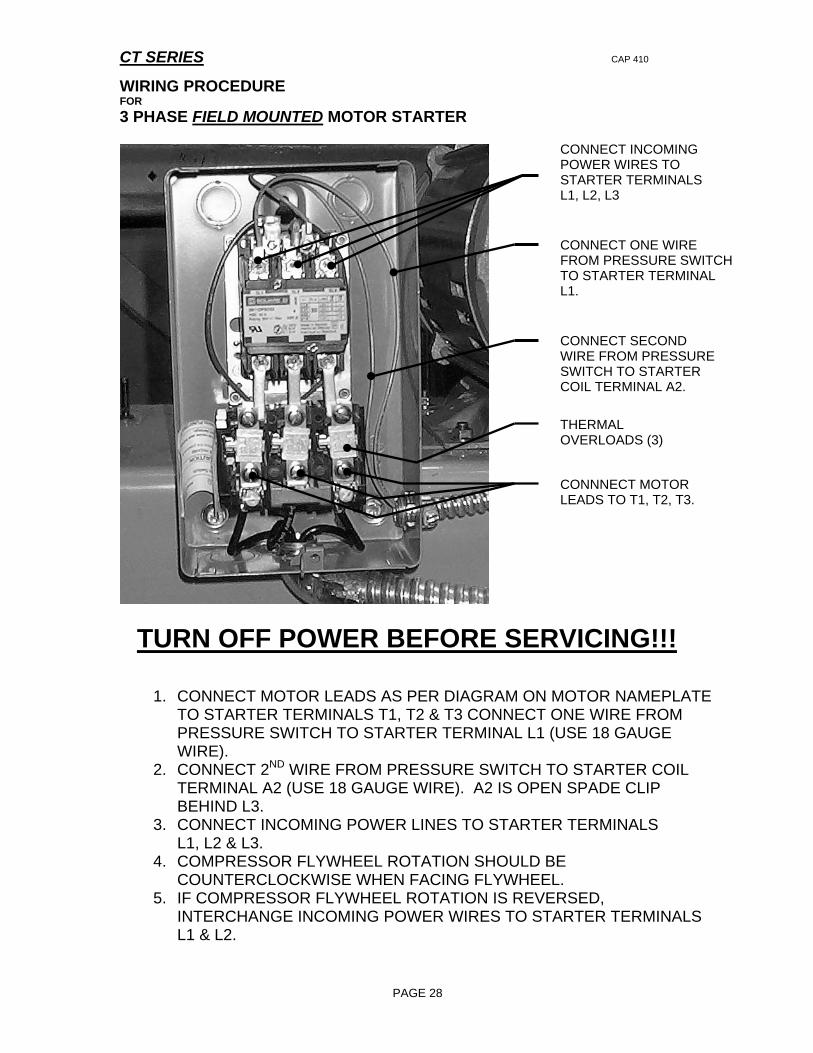
WIRING PROCEDURE FOR 3 PHASE FIELD MOUNTED MOTOR STARTER
CONNECT INCOMING POWER WIRES TO STARTER TERMINALS L1, L2, L3
CONNECT ONE WIRE FROM PRESSURE SWITCHTO STARTER TERMINAL L1.
CONNECT SECOND WIRE FROM PRESSURE SWITCH TO STARTER COIL TERMINAL A2.
CONNNECT MOTOR LEADS TO T1, T2, T3.
THERMAL OVERLOADS (3)
TURN OFF POWER BEFORE SERVICING!!!
1. CONNECT MOTOR LEADS AS PER DIAGRAM ON MOTOR NAMEPLATE TO STARTER TERMINALS T1, T2 & T3 CONNECT ONE WIRE FROM PRESSURE SWITCH TO STARTER TERMINAL L1 (USE 18 GAUGE WIRE).
2. CONNECT 2ND WIRE FROM PRESSURE SWITCH TO STARTER COIL TERMINAL A2 (USE 18 GAUGE WIRE). A2 IS OPEN SPADE CLIP BEHIND L3.
3. CONNECT INCOMING POWER LINES TO STARTER TERMINALS L1, L2 & L3.
4. COMPRESSOR FLYWHEEL ROTATION SHOULD BE COUNTERCLOCKWISE WHEN FACING FLYWHEEL.
5. IF COMPRESSOR FLYWHEEL ROTATION IS REVERSED, INTERCHANGE INCOMING POWER WIRES TO STARTER TERMINALS L1 & L2.
PAGE 28

CT SERIES
WIRING PROCEDURES FOR
1 PHASE FACTORY MOTOR STARTER
CONNECT INCOMING POWER WIRES TO STARTER TERMINALS L1 & L2.
THERMAL OVERLOAD.
TURN OFF POWER BEFORE SERVICING!!!
FACTORY MOTOR STARTERS ARE SUPPLIED WITH PRESSURE SWITCH AND MOTOR CONNECTIONS TO STARTER.
1. CONNECT INCOMING POWER WIRES TO STARTER TERMINALS L1 & L2.
PAGE 29
CT SERIES
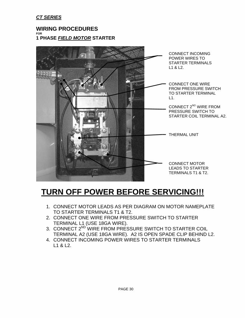
WIRING PROCEDURES FOR 1 PHASE FIELD MOTOR STARTER
CONNECT ONE WIRE FROM PRESSURE SWITCHTO STARTER TERMINAL L1.
CONNECT 2ND WIRE FROM PRESSURE SWITCH TO STARTER COIL TERMINAL A2.
CONNECT INCOMING POWER WIRES TO STARTER TERMINALS L1 & L2.
THERMAL UNIT
CONNECT MOTOR LEADS TO STARTER TERMINALS T1 & T2.
TURN OFF POWER BEFORE SERVICING!!!
1. CONNECT MOTOR LEADS AS PER DIAGRAM ON MOTOR NAMEPLATE TO STARTER TERMINALS T1 & T2.
2. CONNECT ONE WIRE FROM PRESSURE SWITCH TO STARTER TERMINAL L1 (USE 18GA WIRE).
3. CONNECT 2ND WIRE FROM PRESSURE SWITCH TO STARTER COIL TERMINAL A2 (USE 18GA WIRE). A2 IS OPEN SPADE CLIP BEHIND L2.
4. CONNECT INCOMING POWER WIRES TO STARTER TERMINALS L1 & L2.
PAGE 30
CT SERIES CAP 410
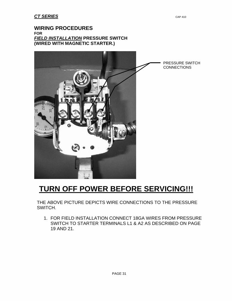
WIRING PROCEDURES FOR FIELD INSTALLATION PRESSURE SWITCH (WIRED WITH MAGNETIC STARTER.)
PRESSURE SWITCH
CONNECTIONS
TURN OFF POWER BEFORE SERVICING!!!
THE ABOVE PICTURE DEPICTS WIRE CONNECTIONS TO THE PRESSURE SWITCH.
1. FOR FIELD INSTALLATION CONNECT 18GA WIRES FROM PRESSURE SWITCH TO STARTER TERMINALS L1 & A2 AS DESCRIBED ON PAGE 19 AND 21.
PAGE 31
CT SERIES CAP 410
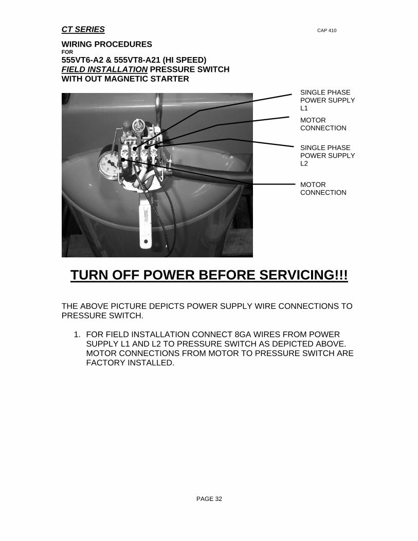
WIRING PROCEDURES FOR 555VT6-A2 & 555VT8-A21 (HI SPEED) FIELD INSTALLATION PRESSURE SWITCH WITH OUT MAGNETIC STARTER
PAGE 32
MOTOR CONNECTION
SINGLE PHASE POWER SUPPLY L1
SINGLE PHASE POWER SUPPLY L2
MOTOR CONNECTION
TURN OFF POWER BEFORE SERVICING!!! THE ABOVE PICTURE DEPICTS POWER SUPPLY WIRE CONNECTIONS TO PRESSURE SWITCH.
1. FOR FIELD INSTALLATION CONNECT 8GA WIRES FROM POWER SUPPLY L1 AND L2 TO PRESSURE SWITCH AS DEPICTED ABOVE. MOTOR CONNECTIONS FROM MOTOR TO PRESSURE SWITCH ARE FACTORY INSTALLED.

CURTIS-TOLEDO INC 1905 KIENLEN AVE., ST. LOUIS, MO 63133 TEL. (800) 925-5431 FAX (314) 381-1439
E-MAIL: [email protected] Website: www.curtistoledo.com