Embed Size (px)
Citation preview

1
Loblaws Inc.,1 President’s Choice Circle,Brampton, OntarioL6Y 5S5
WARNINGYou must read this owner’s guide before operating your gas grill. Failure to follow these instructions could result in fire or explosion that could cause property damage, personal injury or death.For your safety: This gas appliance is designed for outdoor use only and shall not be used in a building, garage or any other enclosed area.Do not use in or on boats or recreational vehicles.
WARNING1. Improper installation, adjustment, alteration, service or maintenance can cause injury or damage to property.2. Read the assembly, installation, operation and
maintenance thoroughly before assembling, installing, or servicing the equipment.
3. Failure to follow these instructions could result in fire or explosion which could cause property damage, personal injury or death.
Stainless Steel 60,000BTU BBQ natural gas
assembly instructions and owner’s guide
MODEL NUMBER:
13 01 3008TG
SERIAL NUMBER:
natural gas
TG3008 NG U&C-2012 FA.indd 1 12-09-26 4:36 PM

2
THIS GAS APPLIANCE IS DESIGNED FOR OUTDOOR USE ONLY.
DANGERIf you smell gas:1. Shut off gas to the appliance.2. Extinguish any open flames.3. Open the lid.4. If odor persists, keep away from the appliance and immediately call your gas supplier or the fire department.
DO NOT RETURN THE BARBECUE TO STORE. For assistance, call Customer Service at 1-800-737-8815
Monday to Friday from 9 a.m. to 5 p.m. Eastern Standard Time.
WARNING: Do not ignite this gas appliance without first reading the operating instructions in this manual.
Save these instructions for future reference.
NOTICE TO INSTALLER: These instructions must be left with the owner and the owner should keep them for future reference.
NOTICE TO CONSUMER: Retain this manual for future reference.
WARNING: Follow all leak check procedures carefully in this manual prior to barbecue operation. Do this even if the barbecue was dealer-assembled.
Do not repair or replace any parts of the grill unless specifically recommended in this manual or by customer service. All other service and maintenance should be performed by a qualified technician.
WARNING: Do not store or use gasoline or other flammable liquids, vapours or materials in the vicinity of this or any other appliance.
Safety Instructions
TG3008 NG U&C-2012 FA.indd 2 12-09-26 4:36 PM

3
BEFORE USING THIS GRILL PERFORM THE SAFETY CHECK.
1. Read and understand the manual.
2. Perform the leak test as found on page 30.
3. Ensure that the barbecue is not positioned under unprotected construction, against a wall, near aluminum or vinyl siding, windows, fencing or anything else that may be flammable.
4. Inspect and clean burner tubes to avoid flash fires caused by spider webs and other blockages. See page 33 for cleaning instructions.
5. Avoid dangerous grease fires by cleaning out the grease cup and grease tray. See instructions on page 33.
6. Before opening the gas supply, ensure that the lid is open, burner knobs are in the off position, gas is turned off and the regulator is properly attached to the tank.
7. Follow the proper lighting procedure on page 31.
Table of Contents
General Warnings 4
Assembly Instructions 6
Connecting to Natural Gas Supply 29
Leak Testing 30
Operating Main Burners 31
Operating the Side Burner 32
Cleaning 32
Seasonal Cleaning 34
Tips for Cooking 35
Trouble Shooting 36
TG3008 NG U&C-2012 FA.indd 3 12-09-26 4:36 PM

4
General WarningsThis barbecue is not convertible to propane. Any attempt to do so could result in injury or damage to property and will void the warranty.
WARNINGS Failure to follow the dangers, warnings and cautions contained in this Owner’s Manual may result in fire or explosion causing property damage, personal injury or death.
Incorrect assembly may be dangerous. Please carefully follow the assembly instructions. Do not assemble with missing or damaged parts. If you do not understand the instructions or need replacement parts, contact Customer Service at 1-800-737-8815.
Check your local building codes for the proper method of installation or in the absence of local codes, with either the National Fuel Gas Code, ANSI Z223.1/NFPA 54, Natural Gas and Propane Installation Code, CSA B149.1, or Propane Storage and Handling Code, B149.2
The use of alcohol, prescription or non-prescription drugs may impair an individual’s ability to properly assemble or safely operate this barbecue.
Always place your barbecue on a hard and level surface. An asphalt surface or wooden deck may not be acceptable.
The gas barbecue should be thoroughly cleaned on a regular basis.
If the barbecue has been stored or left unused for a period of time, it should be checked for gas leaks and burner obstructions before use. See instructions in this manual for correct cleaning and leak testing procedures. Do not enlarge valve orifices or burner ports when cleaning the valves or burners. Follow the proper procedures as outlined in the burner cleaning section of this manual.
Keep ventilation openings clear of debris.
Do not operate the gas barbecue if there is an odor of gas present or a gas leak.
Do not use a flame to check for gas leaks.
Combustible materials should never be within 24 inches (61 cm) of the back or sides of your gas barbecue.
Always position the barbecue where there is ample air flow for combustion and ventilation, but never in the path of a strong wind.
Do not use this barbecue under an overhead combustible surface or covered area such as a gazebo, umbrella porch or awning.
Do not put a barbecue cover or anything flammable on or in the storage area under the barbecue or on the side shelves. Keeping outdoor cooking gas appliance area clear and free from combustible materials, gasoline and other flammable vapors and liquids.
Your gas barbecue should never be used by children. Do not let children or pets play around or below the grill or in the cart. Never allow children or pets to crawl inside the cart. Accessible parts of the barbecue may be very hot.
You should exercise care when operating your gas barbecue. It will be hot during cooking or cleaning and should never be left unattended or moved while in operation.
When using the barbecue do not touch the grill rack, lid, fire box or anything in the immediate vicinity of these parts, as they can become extremely hot and may cause serious burns.
Never lean over an open grill.
Use only dry pot holders and oven mitts. Moist or damp pot holders or oven mitts on hot surfaces may cause burns from steam. Do not use a towel or a bulky cloth in place of pot holders or oven mitts, as they may touch hot portions of the grill rack.
For personal safety, wear appropriate clothing. Loose-fitting clothing should never be worn while using this appliance. Some synthetic fibers are highly flammable and should not be worn while cooking.
Should the burners go out while in operation, turn all gas valves off. Open the lid and wait five minutes before attempting to relight, using the igniting instructions.
Do not use charcoal, lighter fluid or lava rock in your gas barbecue.
Do not use aluminum foil to line the grill racks or the fire box. This can interfere with air flow or trap excessive heat in the fire box or control area.
Should a grease fire occur, turn off all burners and leave lid closed until fire is out.
Only the hose assembly supplied with the unit should be used. Never substitute hoses for those supplied with the grill. If a replacement is necessary contact Customer Service for a replacement.
Do not attempt to disconnect any gas fitting while your barbecue is in operation.
Do not repair or replace any part of the grill unless specifically recommended by the manual or Customer Service. All other service should be referred to a qualified technician.
TG3008 NG U&C-2012 FA.indd 4 12-09-26 4:36 PM
5
Keep any electrical supply cord and the fuel supply hose away from any heated surfaces and the grease cup and tray where hot grease could drip down.
Combustion by-products produced when using this product contain chemicals known to the state of California to cause cancer, birth defects or other reproductive harm.
Do not build this model of grill in any built-in or slide-in construction. Ignoring this warning could cause fire or explosion that can cause property damage, personal injury or death.
Do not heat unopened food containers as a build-up of pressure may cause the container to burst causing injury or damage to property.
This barbecue is not intended for commercial use.
Natural Gas Units Only:Use the hose assembly that is supplied with your gas barbecue.
Do not attempt to disconnect the gas regulator and hose assembly or any gas fitting while your barbecue is in operation.
Your natural gas grill has been designed to operate on natural gas only, at a pressure of seven inches water column (7” W.C.).
Check with your gas utility for local gas pressure, because in some areas natural gas pressure varies. Also, check with your gas company or with local building codes for instructions to install gas supply line or call a licensed and qualified installer.
It is recommended that an ON/OFF manual shut–off valve be installed at the gas supply source:
Outdoors after the gas line exits outside wall and before quick disconnect or before gas supply line enters ground.
Pipe sealing compound or pipe thread tape of the type resistant to the action of natural gas must be used on all male pipe threads. Apply compound or tape to at least the first three to four threads when making connections.
Never store or use gasoline or other volatile substance in the vicinity of this grill.
During high pressure testing, in excess of 1/2 psi (3.5kPa) your gas grill and its individual shutoff valve must be disconnected from the gas supply piping system.
During low pressure testing, equal to or less than 1/2 psi (3.5kPa), your gas grill must be isolated from the gas supply piping system by closing its individual manual shutoff.
Natural Gas Characteristics: Natural Gas is flammable, explosive under pressure and heavier than air so it will settle and pool in low areas and prevent dispersion.
Natural Gas has a distinct smell. You should be aware of this smell.
If you see, smell or hear the hiss of escaping gas from the fuel line:1. Move away from fuel line.2. Do not attempt to correct the problem yourself.3. Call your fire department.
The total consumption (per hour) of this grill with all burners set to “MAX” is 60,000 BTU/hr.
Four main burners: 48,000 BTU/hr
Side burner: 12,000 BTU/hr
TG3008 NG U&C-2012 FA.indd 5 12-09-26 4:36 PM
6
Assembly InstructionsINTRODUCTION
Do not return this product to store.
For assistance call Customer Service at 1-800-737-8815. Please have the following information available.
Serial NumberThe serial number can be found inside the front left door of the barbecue on the top left hand corner of the rating label. It can also be found on the cover of this manual.
Model NumberThe model number is located on the front of this manual and in the top left-hand corner of the rating label.
For easiest assembly:
1. Make sure all the parts are present. If parts are missing or damaged, contact Customer Service.
2. To avoid losing small components, assemble the barbecue on a smooth, level surface.
3. Clear an area large enough to lay out all the components and hardware.
4. You must follow all steps in order to properly assemble your barbecue.
5. To properly align the frame and doors, assemble grill on a flat and level surface.
To complete your assembly you will need:
1. A #2 Phillips head screw driver
2. Leak detection solution see (Leak Detection section on page 30)
Parts List
CODE PART QTY
1 Fire Box Assembly 1 2 Warming Rack 1 3 Cooking Grill 2 4 Heat Tent 4 5 Grease Tray Assembly 1 6 Grease Cup 1 7 Side Burner Grate 1 8 Side Burner Electrode 1 9 Side Burner Assembly 1 10 Side Burner 1 11 Side Burner Control Panel 1 12 Side Burner Knob 1 13 Side Table Assembly 1 14 Side Table Control Panel 1 15 Side Table Handle 1 16 Left Front Leg 1 17 Left Rear Leg 1 18 Right Front Leg 1 19 Right Rear Leg 1 20 Door Transom 1 21 Left Cart Side Panel 1 22 Right Cart Side Panel 1 23 Left Front Door 1 24 Right Front Door 1 25 Door Handle 2 26 Bottom Shelf Assembly 1 27 Hose Restraint Clip 1 28 Cart Support Bracket 2 29 Bottom Skirt - Front 1 30 Bottom Skirt - Left 1 31 Bottom Skirt - Right 1 32 Caster 2 33 Locking Caster 2 34 Lighting Rod 1
TG3008 NG U&C-2012 FA.indd 6 12-09-26 4:36 PM

7
Parts Diagram
TG3008 NG U&C-2012 FA.indd 7 12-09-26 4:36 PM

8
Hardware Reference Diagram
CODE PART QTY
A M6x12mm Bolt 38 B M6x8mm Bolt 4 C M5x8mm Bolt 4 D M6x40mm Bolt 2 E Washer 6 F M4x10mm Bolt 12
1:1 SCALE
TG3008 NG U&C-2012 FA.indd 8 12-09-26 4:36 PM

9
Assembly
STEP 1Attach the Left Front Leg (16) and Right Front Leg (18) to the Bottom Shelf Assembly (26) using one M6x12mm Bolt on each leg (A). Tighten the bolts with the screwdriver.
STEP 2Attach the Left Rear Leg (17) and Right Rear Leg (19) to the Bottom Shelf Assembly (26) using one M6x12mm Bolt (A) on each leg.Tighten the bolts with the screwdriver.
16 26
26
18
17
19
A x2
A x2
1:1 SCALE
TG3008 NG U&C-2012 FA.indd 9 12-09-26 4:36 PM

10
Assembly
STEP 3A. Attach the Right Cart Side Panel (22) to the Right Front Leg (18) and Right Rear Leg (19) using four M6x12mm Bolts (A). Tighten the bolts with the screwdriver.
B. Attach one of the Cart Support Brackets (28) to the Right Rear Leg (19) and the Bottom Shelf Assembly (26) using two M6x12mm Bolts (A). Tighten the bolts with the screwdriver.
22
19
19
18
28
A x4
A x2
TG3008 NG U&C-2012 FA.indd 10 12-09-26 4:36 PM

11
Assembly
STEP 4A. Attach the Left Cart Side Panel (21) to the Left Front Leg (16) and Left Rear Leg (17) using four M6x12mm Bolts (A). Tighten the bolts with the screwdriver.
B. Attach the Cart Support Bracket (28) to the Left Rear Leg (17) and the Bottom Shelf Assembly (26) using two M6x12mm Bolts (A). Tighten the bolts with the screwdriver.
21
16 17
17
28
A x4
A x2
TG3008 NG U&C-2012 FA.indd 11 12-09-26 4:36 PM

12
Assembly
STEP 5
A. Attach the two Locking Casters (33) to the Left Rear Leg (17) and the Right Rear Leg (19).
B. Attach the two Casters (32) to the Left Front Leg (16) and the Right Front Leg (18).
STEP 6Attach the Bottom Skirt Front (29) on the Bottom Shelf Assembly (26) using four M4x10mm Bolts (F). Align the edges of the Bottom Skirt Front with the edges of the Bottom Shelf Assembly. Tighten the bolts with the screwdriver.
33
33
32
32
17
16
19
18
29
26F x4
TG3008 NG U&C-2012 FA.indd 12 12-09-26 4:36 PM
13
Assembly
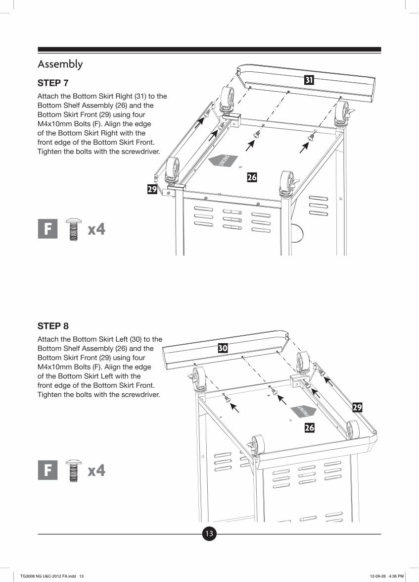
STEP 7Attach the Bottom Skirt Right (31) to the Bottom Shelf Assembly (26) and the Bottom Skirt Front (29) using four M4x10mm Bolts (F). Align the edge of the Bottom Skirt Right with the front edge of the Bottom Skirt Front. Tighten the bolts with the screwdriver.
STEP 8Attach the Bottom Skirt Left (30) to the Bottom Shelf Assembly (26) and the Bottom Skirt Front (29) using four M4x10mm Bolts (F). Align the edge of the Bottom Skirt Left with the front edge of the Bottom Skirt Front. Tighten the bolts with the screwdriver.
29
29
30
31
26
26
F x4
F x4
TG3008 NG U&C-2012 FA.indd 13 12-09-26 4:36 PM
14
Assembly
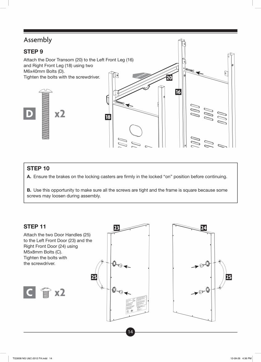
STEP 9Attach the Door Transom (20) to the Left Front Leg (16) and Right Front Leg (18) using two M6x40mm Bolts (D). Tighten the bolts with the screwdriver.
STEP 10A. Ensure the brakes on the locking casters are firmly in the locked “on” position before continuing.
B. Use this opportunity to make sure all the screws are tight and the frame is square because some screws may loosen during assembly.
STEP 11Attach the two Door Handles (25) to the Left Front Door (23) and the Right Front Door (24) using M5x8mm Bolts (C). Tighten the bolts with the screwdriver.
20
16
23
25 25
24
18D x2
C x2
TG3008 NG U&C-2012 FA.indd 14 12-09-26 4:36 PM
15
Assembly
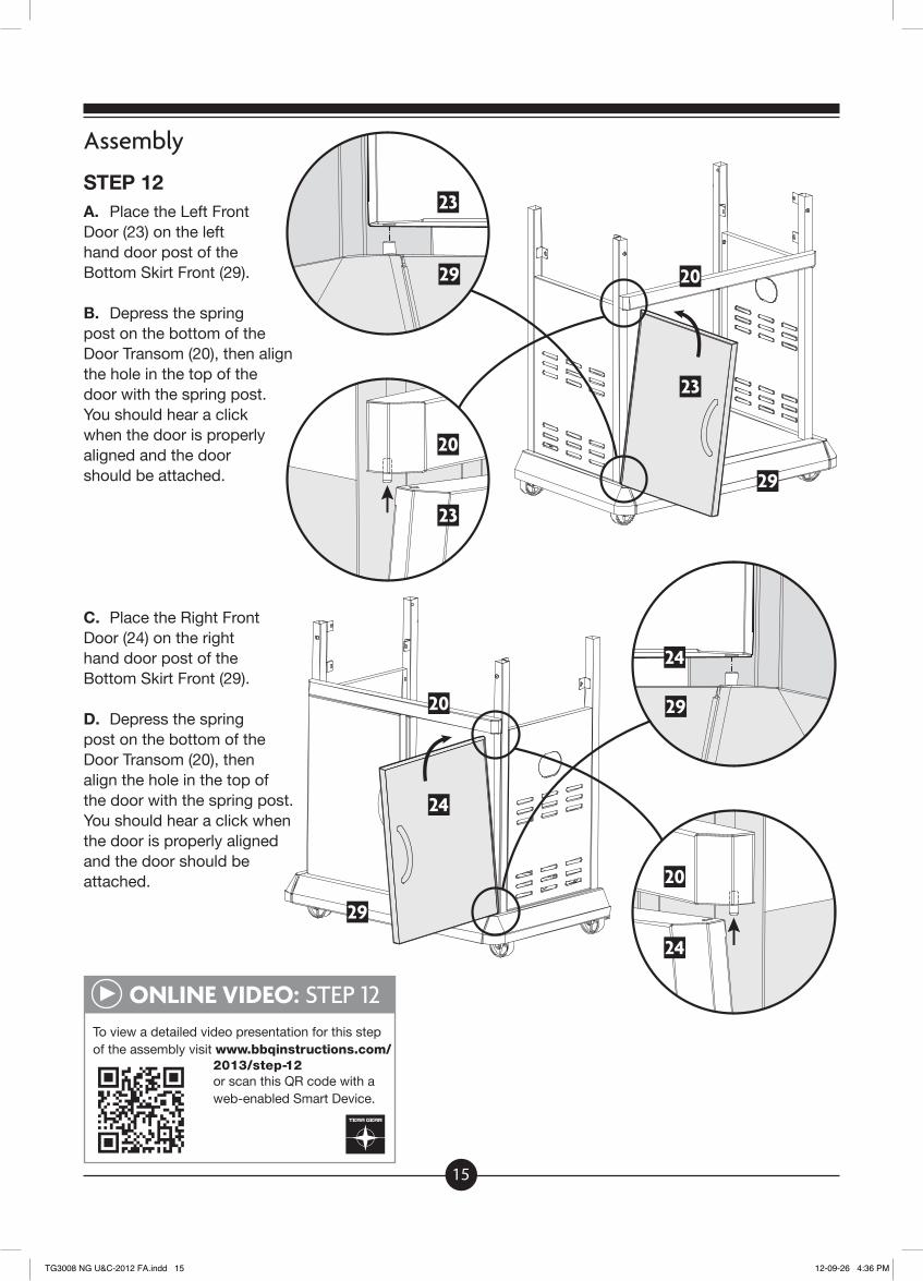
STEP 12A. Place the Left Front Door (23) on the left hand door post of the Bottom Skirt Front (29).
B. Depress the spring post on the bottom of the Door Transom (20), then align the hole in the top of the door with the spring post. You should hear a click when the door is properly aligned and the door should be attached.
C. Place the Right Front Door (24) on the right hand door post of the Bottom Skirt Front (29).
D. Depress the spring post on the bottom of the Door Transom (20), then align the hole in the top of the door with the spring post. You should hear a click when the door is properly aligned and the door should be attached.
29
29
29
29
23
24
20
20
23
24
23
24
20
20
ONLINE VIDEO: STEP 12To view a detailed video presentation for this stepof the assembly visit www.bbqinstructions.com/
2013/step-12or scan this QR code with a web-enabled Smart Device.
TG3008 NG U&C-2012 FA.indd 15 12-09-26 4:36 PM
16
Assembly
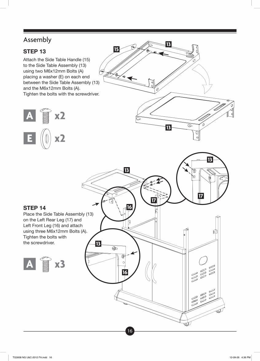
STEP 13Attach the Side Table Handle (15) to the Side Table Assembly (13) using two M6x12mm Bolts (A) placing a washer (E) on each end between the Side Table Assembly (13) and the M6x12mm Bolts (A). Tighten the bolts with the screwdriver.
STEP 14Place the Side Table Assembly (13) on the Left Rear Leg (17) and Left Front Leg (16) and attach using three M6x12mm Bolts (A). Tighten the bolts with the screwdriver.
1513
13
13
13
13
1717
16
16
A x2
A x3
E x2
TG3008 NG U&C-2012 FA.indd 16 12-09-26 4:36 PM
17
34
Assembly
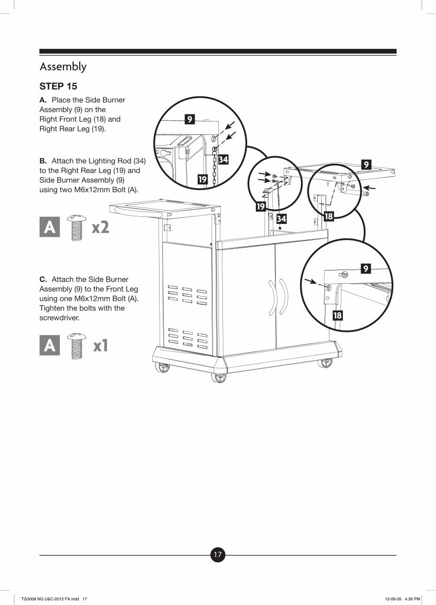
STEP 15A. Place the Side Burner Assembly (9) on the Right Front Leg (18) and Right Rear Leg (19).
B. Attach the Lighting Rod (34) to the Right Rear Leg (19) and Side Burner Assembly (9) using two M6x12mm Bolt (A).
C. Attach the Side Burner Assembly (9) to the Front Leg using one M6x12mm Bolt (A). Tighten the bolts with the screwdriver.
9
9
9
18
18
19
19
A x2
A x1
34
TG3008 NG U&C-2012 FA.indd 17 12-09-26 4:36 PM
18
Assembly
STEP 16
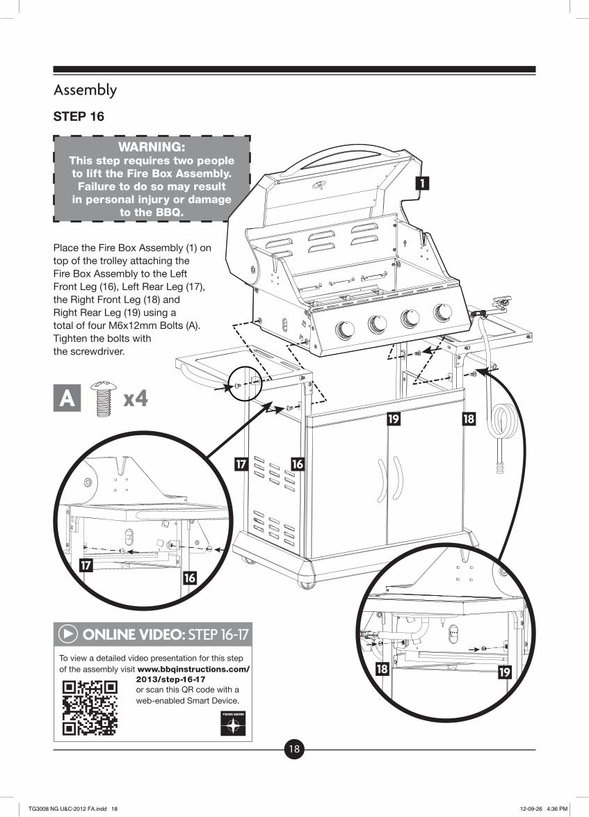
WARNING: This step requires two people to lift the Fire Box Assembly. Failure to do so may result
in personal injury or damage to the BBQ.
Place the Fire Box Assembly (1) on top of the trolley attaching the Fire Box Assembly to the Left Front Leg (16), Left Rear Leg (17), the Right Front Leg (18) and Right Rear Leg (19) using a total of four M6x12mm Bolts (A). Tighten the bolts with the screwdriver.
ONLINE VIDEO: STEP 16-17To view a detailed video presentation for this stepof the assembly visit www.bbqinstructions.com/
2013/step-16-17or scan this QR code with a web-enabled Smart Device.
A x4
1
1617
1617
19
19
18
18
TG3008 NG U&C-2012 FA.indd 18 12-09-26 4:36 PM
19
Assembly
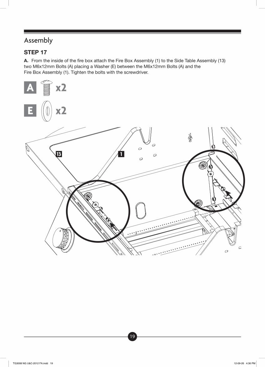
STEP 17A. From the inside of the fire box attach the Fire Box Assembly (1) to the Side Table Assembly (13) two M6x12mm Bolts (A) placing a Washer (E) between the M6x12mm Bolts (A) and the Fire Box Assembly (1). Tighten the bolts with the screwdriver.
113
A x2
E x2
TG3008 NG U&C-2012 FA.indd 19 12-09-26 4:36 PM
20
Assembly
STEP 17
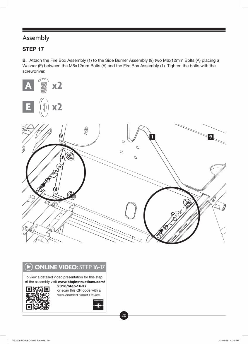
B. Attach the Fire Box Assembly (1) to the Side Burner Assembly (9) two M6x12mm Bolts (A) placing a Washer (E) between the M6x12mm Bolts (A) and the Fire Box Assembly (1). Tighten the bolts with the screwdriver.
ONLINE VIDEO: STEP 16-17To view a detailed video presentation for this stepof the assembly visit www.bbqinstructions.com/
2013/step-16-17or scan this QR code with a web-enabled Smart Device.
A x2
E x2
91
TG3008 NG U&C-2012 FA.indd 20 12-09-26 4:36 PM
21
Assembly
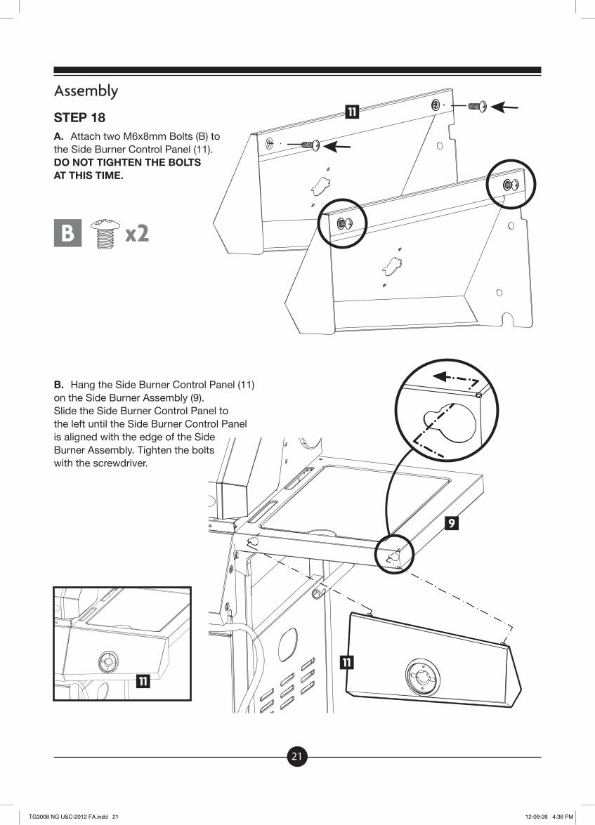
STEP 18A. Attach two M6x8mm Bolts (B) tothe Side Burner Control Panel (11). DO NOT TIGHTEN THE BOLTS AT THIS TIME.
B. Hang the Side Burner Control Panel (11) on the Side Burner Assembly (9). Slide the Side Burner Control Panel to the left until the Side Burner Control Panel is aligned with the edge of the Side Burner Assembly. Tighten the bolts with the screwdriver.
11
11
B x2
11
9
TG3008 NG U&C-2012 FA.indd 21 12-09-26 4:36 PM
22
Assembly
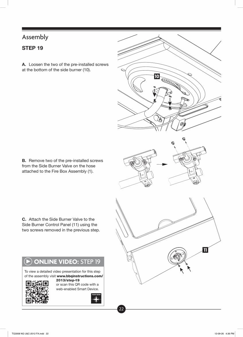
STEP 19
A. Loosen the two of the pre-installed screws at the bottom of the side burner (10).
B. Remove two of the pre-installed screws from the Side Burner Valve on the hose attached to the Fire Box Assembly (1).
C. Attach the Side Burner Valve to the Side Burner Control Panel (11) using the two screws removed in the previous step.
ONLINE VIDEO: STEP 19To view a detailed video presentation for this stepof the assembly visit www.bbqinstructions.com/
2013/step-19or scan this QR code with a web-enabled Smart Device.
10
11
TG3008 NG U&C-2012 FA.indd 22 12-09-26 4:36 PM

23
Assembly
STEP 19
D. Insert the nozzle of the Side Burner Valve into the supply pipe of the Side Burner. Once aligned tighten the two screws on the Side Burner (10) that were loosened in step 19-A to the Side Burner Assembly (9).
IMPORTANT: Make sure that the valve nozzle is properly inserted and aligned.
E. Adust the Side Burner Control Panel (11) so that it is aligned with the front of the Main Control Panel of the Fire Box Assembly (1). Attach the Side Table Control Panel to the Fire Box Assembly using two M6x12mm Bolts (A). Tighten the Bolts with the screwdriver.
10
10
9
9
A x211
TG3008 NG U&C-2012 FA.indd 23 12-09-26 4:36 PM
24
Assembly
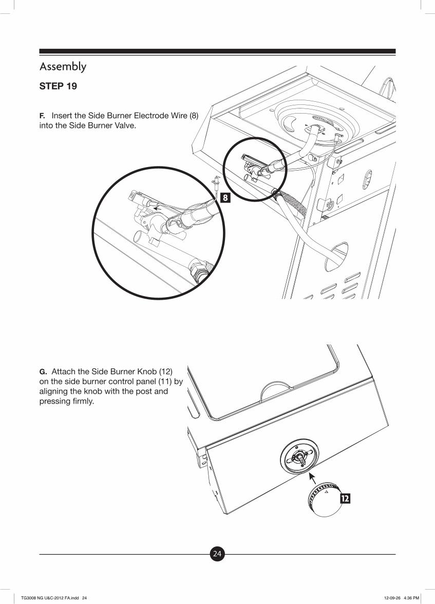
STEP 19
F. Insert the Side Burner Electrode Wire (8) into the Side Burner Valve.
G. Attach the Side Burner Knob (12) on the side burner control panel (11) by aligning the knob with the post and pressing firmly.
8
12
TG3008 NG U&C-2012 FA.indd 24 12-09-26 4:36 PM

25
Assembly
STEP 20
A. Attach two M6x8mm Bolts (B) to the Side Table Control Panel (14). DO NOT TIGHTEN THE BOLTS AT THIS TIME.
B. Hang the Side Table Control Panel (14) on the Side Table Assembly (13). Slide the Side Table Control Panel (14) to the right until the panel is aligned with the edge of the Side Shelf Assembly. Tighten the bolts with the screwdriver.
C. Adjust the Side Table Control Panel (14) so that it is aligned with the front of the Main Control Panel of the Fire Box Assembly (1). Attach the Side Table Control Panel to the Fire Box Assembly using two M6x12mm Bolts (A). Tighten the bolts with the screwdriver.
14
14
13
A x2
B x2
TG3008 NG U&C-2012 FA.indd 25 12-09-26 4:36 PM
26
Assembly
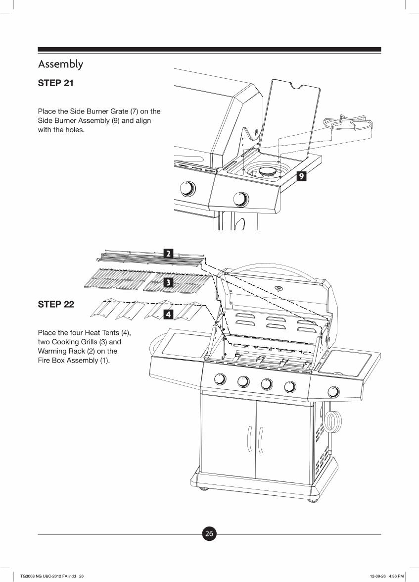
STEP 21
Place the Side Burner Grate (7) on the Side Burner Assembly (9) and align with the holes.
STEP 22
Place the four Heat Tents (4), two Cooking Grills (3) and Warming Rack (2) on the Fire Box Assembly (1).
9
4
3
2
TG3008 NG U&C-2012 FA.indd 26 12-09-26 4:36 PM

27
Assembly
STEP 23
A. From the back of the grill slide the Grease Tray Assembly (5) beneath the Fire Box Assembly (1).
B. Slide the Grease Cup (6) into the channels at the bottom of the Grease Tray Assembly (5).
5
5
5
TG3008 NG U&C-2012 FA.indd 27 12-09-26 4:36 PM

28
Assembly
STEP 24
A. Thread the natural gas hose through the oval opening of the Right Cart Side Panel (22). Be sure that the hose does not touch the Fire Box Assembly (1) or Grease Tray (5) because they become hot during use.
B. Attach Hose Restraint Clip (27) to the Bottom Shelf Assembly (26) using two M6x12 screws (A).
A x2
22
27
26
1
5
TG3008 NG U&C-2012 FA.indd 28 12-09-26 4:36 PM
29
Assembly
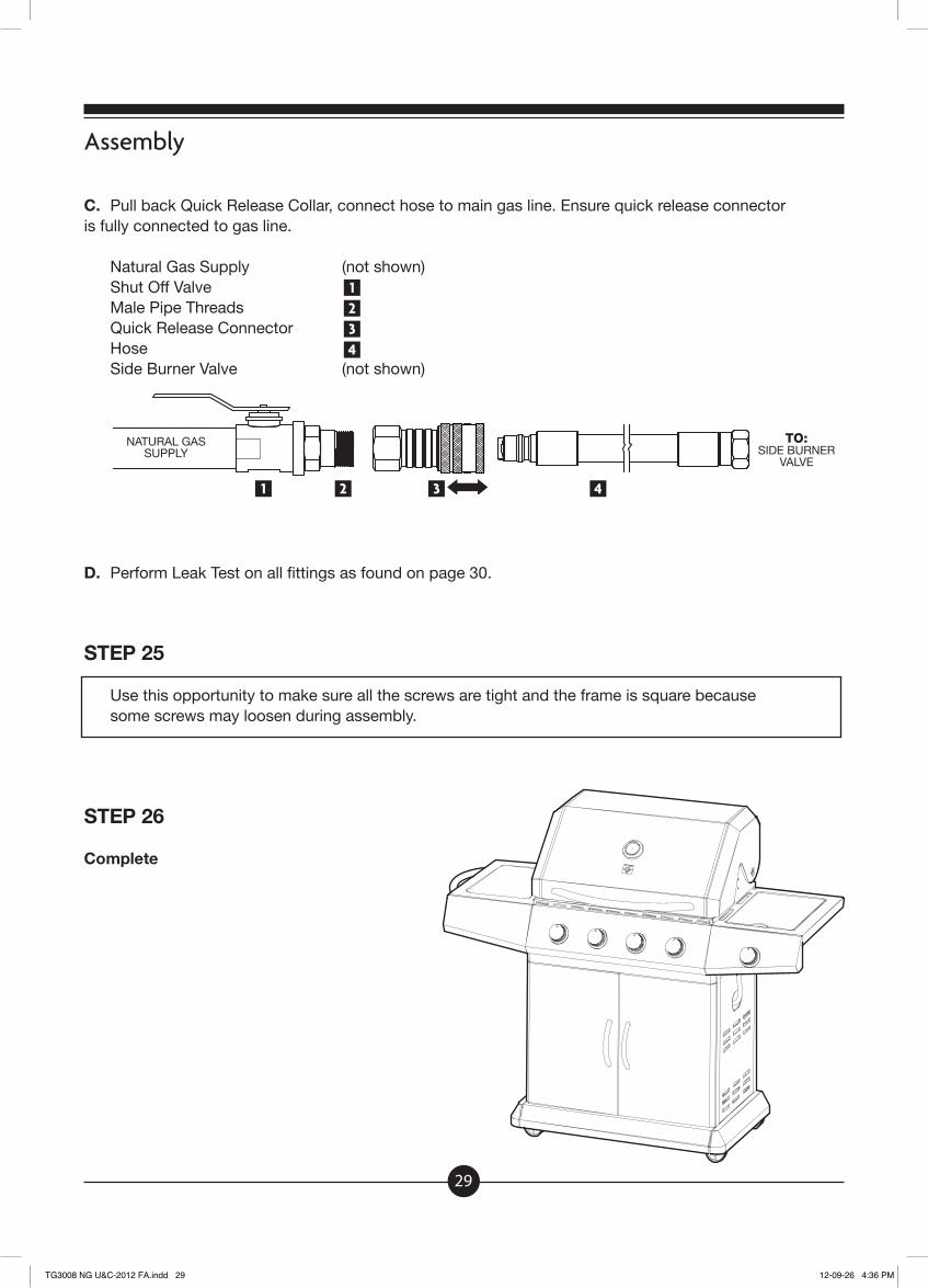
C. Pull back Quick Release Collar, connect hose to main gas line. Ensure quick release connector is fully connected to gas line.
Natural Gas Supply (not shown) Shut Off Valve Male Pipe Threads Quick Release Connector Hose Side Burner Valve (not shown)
D. Perform Leak Test on all fittings as found on page 30.
STEP 25
Use this opportunity to make sure all the screws are tight and the frame is square because some screws may loosen during assembly.
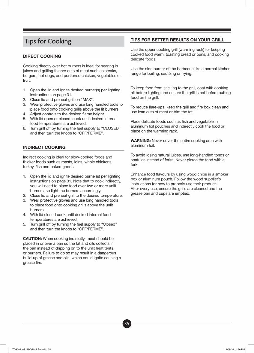
STEP 26
Complete
1234
1 2 3 4
NATURAL GAS SUPPLY
TO:SIDE BURNER
VALVE
TG3008 NG U&C-2012 FA.indd 29 12-09-26 4:36 PM

30
Checking for Leaks
It is important to regularly check your hoses and connections for leaks. Failure to do so could result in fire or explosion which could cause property damage, personal injury or death. This test should be conducted regularly to ensure that the gas appliance and hose are in good working order and operates safely.
DANGER: Do not use an open flame to test for leaks. Do not smoke and be sure there are no sparks or open flames in the area while you perform the leak test. Sparks or open flames could result in fire or explosion which could cause property damage, personal injury or death.
The connections should be leak tested every time you disconnect and reconnect a gas fitting.
Burner Connections 1. Make sure the hose connections are securely fastened
to the burner. If your unit was assembled for you, visually check the connection between the burner venturi pipe and orifice. Make sure the burner venturi pipe fits over the orifice.
2. If the burner pipe does not rest flush to the orifice, please contact Customer Service at 1-800-737-8815 for assistance.
WARNING: Failure to inspect this connection or follow these instructions could cause fire or explosion which could cause property damage, personal injury or death.
Ensure that the barbecue is in a well ventilated area.
LEAK-TESTING THE CONNECTIONS
1. Mix ¼ cup of liquid dishwashing soap with ¾ of a cup of water.
2. Make sure control knobs are “OFF/FERMÉ”.3. Open the gas control valve on the Natural Gas fuel line.4. Spoon the mix over the connections or use a small
paintbrush to coat the all the connections, hoses and fittings including the manifold pipe assembly (the steel pipe that connects to all the burners.)
5. If you see growing bubbles after several attempts, close the gas control valve on the Natural Gas fuel line. and disconnect it. Do not try to repair. Call Customer Service at 1-800-737-8815 to order replacement parts.
6. If no bubbles appear after one minute, close the gas control valve on the Natural Gas fuel line, wipe away solution with water, then wipe dry.
HOSE INSPECTION
The hose should be inspected for any signs of cracking or damage.
WARNING: Check hose before each use of barbecue for nicks, cracking, abrasions or cuts. If the hose is found to be damaged in any way, do not use the barbecue. Replace using only authorized replacement hose. Contact Customer Service at 1-800-737-8815 immediately for replacement parts.
TG3008 NG U&C-2012 FA.indd 30 12-09-26 4:36 PM
31
Operating Main Burners
LIGHTING THE MAIN BURNER
A) Open the barbecue lid. Attempting to light the burner with the lid closed may cause an explosion.
B) Ensure all knobs are in the “OFF/FERMÉ” position. Open the gas control valve on the Natural Gas fuel line.
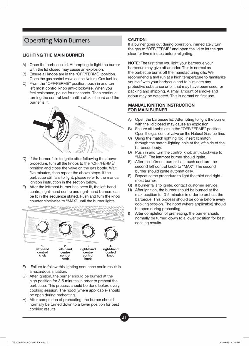
C) From the “OFF/FERMÉ” position, push in and turn left most control knob anti-clockwise. When you feel resistance, pause four seconds. Then continue turning the control knob until a click is heard and the burner is lit.
D) If the burner fails to ignite after following the above procedure, turn all the knobs to the “OFF/FERMÉ” position and close the valve on the gas bottle. Wait five minutes, then repeat the above steps. If the barbecue still fails to light, please refer to the manual ignition instruction in the section below.
E) After the leftmost burner has been lit, the left-hand centre, right-hand centre and right-hand burners can be lit in the sequence stated. Push and turn the knob counter clockwise to “MAX” until the burner lights.
F) Failure to follow this lighting sequence could result in a hazardous situation.
G) After ignition, the burner should be burned at the high position for 3-5 minutes in order to preheat the barbecue. This process should be done before every cooking session. The hood (where applicable) should be open during preheating.
H) After completion of preheating, the burner should normally be turned down to a lower position for best cooking results.
CAUTION:If a burner goes out during operation, immediately turn the gas to “OFF/FERMÉ” and open the lid to let the gas clear for five minutes before relighting.
NOTE: The first time you light your barbecue your barbecue may give off an odor. This is normal as the barbecue burns off the manufacturing oils. We recommend a trial run at a high temperature to familiarize yourself with your barbecue and to eliminate any protective substance or oil that may have been used for packing and shipping. A small amount of smoke and odour may be detected. This is normal on first use.
MANUAL IGNITION INSTRUCTION FOR MAIN BURNER
A) Open the barbecue lid. Attempting to light the burner with the lid closed may cause an explosion.
B) Ensure all knobs are in the “OFF/FERMÉ” position. Open the gas control valve on the Natural Gas fuel line.
C) Using the match lighting rod, insert lit match through the match-lighting hole at the left side of the barbecue body.
D) Push in and turn the control knob anti-clockwise to “MAX”. The leftmost burner should ignite.
E) After the leftmost burner is lit, push and turn the second left control knob to “MAX”. The second burner should ignite automatically.
F) Repeat same procedure to light the third and right-most burner.
G) If burner fails to ignite, contact customer service.H) After ignition, the burner should be burned at the
max position for 3-5 minutes in order to preheat the barbecue. This process should be done before every cooking session. The hood (where applicable) should be open during preheating.
I) After completion of preheating, the burner should normally be turned down to a lower position for best cooking results.
1.left-handcontrolknob
2.left-hand
centrecontrolknob
3.right-hand
centrecontrolknob
4.right-hand
controlknob
TG3008 NG U&C-2012 FA.indd 31 12-09-26 4:36 PM

32
Operating the Side Burner
LIGHTING THE SIDE BURNER
A) Open the side burner hood.B) Ensure side burner is clear.C) Set the control knob to off and turn on the gas supply.D) Push in and turn the control knob anti-clockwise to
“MAX”. E) Push the ignition button several times and the burner
should ignite. F) If the burner fails to ignite after above procedure, turn
the knob to “OFF/FERMÉ” and close the gas valve. Wait five minutes and then repeat the above steps. If the barbecue still fails to light, please refer to the manual ignition instruction in the section below.
MANUAL IGNITION INSTRUCTION FOR THE SIDE BURNER
A) Open the side burner hood.B) Ensure side burner is clear.C) Set the control knob to “OFF/FERMÉ” and turn on
the gas supply.D) Using the match lighting rod, apply a lit match on the
gap to burner ports. E) Push and turn the control knob anti-clockwise to
“MAX” position and the burner should ignite. If the burner fails to ignite, contact customer service.
CleaningYour barbecue should be cleaned frequently for long life. Some parts of the barbecue need to be cleaned after each use.
All cleaning and maintenance should be done when the grill is cool and the fuel supply is disconnected.Do not clean any parts of the barbecue in a self-cleaning oven. The extreme heat will damage the finish.
Do not power wash your grill. The high pressure can damage your barbecue.
BURNERS
Your barbecue is a target for spiders and other insects. They can nest in the venturi section of the burner tubes. This blocks the normal gas flow, and can cause the gas to flow back out of the combustion air opening. This could result in a fire in and around the combustion air openings or under the control panel, causing serious damage to your barbecue.
The burner tube combustion air opening is fitted with a stainless steel screen to prevent spiders and other insects from accessing to the burner tubes through the combustion air openings.
We recommend that you inspect the spider/insect screens at least once a year. Also, inspect and clean the spider/insect screens if any of the following symptoms should ever occur:A) Gas is smelled in conjunction with burner flames that
appear yellow and lazy.B) Barbecue does not reach temperature.C) Barbecue heats unevenly.D) One or more of the burners do not ignite.
DANGER: Failure to correct the above mentioned symptoms may result in fire or explosion which could cause property damage, personal injury or death.
TG3008 NG U&C-2012 FA.indd 32 12-09-26 4:36 PM

33
INSPECTION AND CLEANING OF THE BURNERS AND SPIDER/INSECT SCREENS
1. Turn off the main burners per instructions on page 31.2. To inspect the spider/insect screens, remove the
burners. If there is dust or dirt on the screens, remove the burners to clean the screens.
3. Brush the spider/insect screens lightly with a soft bristle brush (e.g. an old toothbrush).
CAUTION: Do not clean the spider/insect screens with hard or sharp tools. Do not dislodge the spider/insect screens or enlarge the screen openings.
4. Lightly tap the burner to get debris and dirt out of the burner tube. Once the spider/ insect screens and burners are clean, replace the burner.
5. If a spider/insect screen becomes damaged or cannot be cleaned, please contact Customer Service at 1-800-737-8815.
6. If holes are clogged, use a thin straightened paper clip to open them. Never use a wire with a larger diameter than the hole. If the hole is enlarged, the burners will not burn properly.
CAUTION: Never use a toothpick to clean out the burner holes as it may break off and clog the port.
If the burners are damaged, contact Customer Service for replacement parts.
BURNER FLAME PATTERN
The barbecue burners have been factory set for the correct air and gas mixture. The correct flame pattern is shown in illustration and described below:A) Burner tube B) Tips occasionally flicker yellow C) Light blue D) Dark blue
If the flames do not appear to be uniform throughout the burner tube, follow the burner cleaning procedures.
CLEANING THE SIDE BURNER
1. Turn off the side burner per instructions on page 31.2. Clean the exterior of the side burner with a brass
brush. 3. Clear a clogged port with a straightened paper clip or
steel wire.
Never enlarge the burner ports.
CAUTION: Never use a toothpick to clean out the burner holes as it may break off and clog the port.
CLEANING THE GRILLS
It is important to clean your grill after each use because grease, salt and acidic marinades can damage the paint and cause the grills to rust.
It is best to clean the grills immediately after cooking, while they are still warm and before the grease and deposits have had time to harden and dry out.
1. Turn off the grill per instructions on page 31.2. Wearing a barbecue mitt, use a long-handled grill
brush to scrub the grills. Be careful not to touch the hot grills.
GREASE TRAPS
It is important to clean the grease cup and tray after every use. If oil builds up in the grease cup and grease tray, a dangerous grease fire could occur.
Do not line the grease cup or grease tray with aluminum foil because the foil may prevent grease from draining properly.
1. Ensure the barbecue is turned off and allow it to fully cool. Caution: The grease tray, cup and its contents may still be warm. Be sure they have fully cooled before handling.
2. Turn the barbecue around so you are able to access the back of the grill. Remove the grease cup and the grease tray.
3. Scrape grease from inside the tray and cup using a spatula and a moist cloth. Dry fully to prevent rust.
4. Replace grease tray and then grease cup.
A
B
CD
TG3008 NG U&C-2012 FA.indd 33 12-09-26 4:36 PM
34
CLEANING YOUR HEAT TENTS
The heat tents are an important part of your barbecue. They ensure drippings do not hit your burners directly, which could cause a dangerous flare-up or grease fire. They also allow for drippings to impart that smoky flavour that is associated with barbecued food.
WARNING: Do not use your barbecue without the heat tents. Doing so may result in a dangerous flare-ups or grease fire.
It is important to regularly clean your heat tents because the grease, salt and acidic marinades can cause the heat tents to rust. The degree of damage may not be apparent under the grease and dirt.
Remove and clean the heat tents after every other use.
1. Allow grill to completely cool before cleaning.2. Use a grill brush to clean the heat tents. For stubborn
dirt, use a mild soap with warm water. Be sure to dry thoroughly.
Heat tents may need replacing. Please contact Customer Service at 1-800-737-8815 to order replacement parts.
BARBECUE HOUSING
A properly-sized barbecue cover is essential to the long life of your barbecue.
Under extreme conditions, stainless steel can rust. Rust will be more likely in coastal regions where the salt spray from the ocean may cause rusting.
Wipe the grill down with a soft cloth and soap and water solution. Be careful to scrub in the same direction as the grain of the stainless steel. Do not use abrasive cleaners because you may scratch the surface of the stainless steel.
Some of the supports and side panels are painted silver. To protect the painted surface, do not use abrasive cleaners or harsh chemicals. Using such cleaners or chemicals may result in rust.
The inside of the lid is stainless steel and aluminum, and therefore is not painted. If any material starts to flake off, it is likely burned on grease that has dried out. To remove, wipe with a damp cloth.
Seasonal Cleaning
CLOSING YOUR BARBECUE FOR THE WINTER
It is important that your barbecue is properly closed for the winter. Even if you plan on grilling during the winter, it is important that the grill is prepared for the winter.
1. Clean the grill making sure that the grease tray and cup are cleaned.
2. Wipe down the grills and racks so they are free of oil and grease. The natural salts found in food can cause rusting.
3. Check for any loose parts and tighten all screws.4. Remove grills, warming rack, heat plates and side
burner rack. Clean with a soap and water solution then wipe dry. Store indoors in a cool, dry place.
5. Make sure that the vents on the outside of the grill are clear. Debris or oil and grease may clog the openings.
6. Turn off the gas at the source and turn all the knobs to “OFF/FERMÉ”.
7. Cover your barbecue with a suitable cover. A proper cover will help to keep the snow, ice and rain away from your barbecue.
8. Ensure that snow, ice and water will not collect or pool at the bottom of your grill or on the bottom shelf as this may cause rusting.
9. Ensure that the grill is not directly under any eaves troughs, edges of the roof, or trees. Falling ice and snow can damage the barbecue.
OPENING YOUR BARBECUE FOR THE SPRING
1. Clean out any debris or dirt that may have accumulated in or on the grill. Wipe down the barbecue and the grills.
2. Check for rust on the barbecue.3. Check to make sure the burners are clear and there
are no spider webs or other insects in the burners as described on page 33.
4. Reinstall the grills.5. Perform the Leak Test. See page 30 and check the
hose for any damage. If the hose or any of the fittings are damaged or leaking contact Customer Service at 1-800-737-8815.
6. Check for any lose parts and tighten all screws.7. Check knobs and regulators for damage8. Check grills for any rust or damage.9. Check the propane tank for any damage. If the tank
is damaged, contact your propane tank supplier. 10. Visually check the burner flames. Use the illustration
on page 33 to ensure the burners are running properly.
TG3008 NG U&C-2012 FA.indd 34 12-09-26 4:36 PM
35
Tips for Cooking
DIRECT COOKING
Cooking directly over hot burners is ideal for searing in juices and grilling thinner cuts of meat such as steaks, burgers, hot dogs, and portioned chicken, vegetables or fruit.
1. Open the lid and ignite desired burner(s) per lighting instructions on page 31.
2. Close lid and preheat grill on “MAX”.3. Wear protective gloves and use long handled tools to
place food onto cooking grills above the lit burners. 4. Adjust controls to the desired flame height. 5. With lid open or closed, cook until desired internal
food temperatures are achieved.6. Turn grill off by turning the fuel supply to “CLOSED”
and then turn the knobs to “OFF/FERMÉ”.
INDIRECT COOKING
Indirect cooking is ideal for slow-cooked foods and thicker foods such as roasts, loins, whole chickens, turkey, fish and baked goods.
1. Open the lid and ignite desired burner(s) per lighting instructions on page 31. Note that to cook indirectly, you will need to place food over two or more unlit burners, so light the burners accordingly.
2. Close lid and preheat grill to the desired temperature.3. Wear protective gloves and use long handled tools
to place food onto cooking grills above the unlit burners.
4. With lid closed cook until desired internal food temperatures are achieved.
5. Turn grill off by turning the fuel supply to “Closed” and then turn the knobs to “OFF/FERMÉ”.
CAUTION: When cooking indirectly, meat should be placed in or over a pan so the fat and oils collects in the pan instead of dripping on to the unlit heat tents or burners. Failure to do so may result in a dangerous build-up of grease and oils, which could ignite causing a grease fire.
TIPS FOR BETTER RESULTS ON YOUR GRILL
Use the upper cooking grill (warming rack) for keeping cooked food warm, toasting bread or buns, and cooking delicate foods.
Use the side burner of the barbecue like a normal kitchen range for boiling, sautéing or frying.
To keep food from sticking to the grill, coat with cooking oil before lighting and ensure the grill is hot before putting food on the grill.
To reduce flare-ups, keep the grill and fire box clean and use lean cuts of meat or trim the fat.
Place delicate foods such as fish and vegetable in aluminum foil pouches and indirectly cook the food or place on the warming rack.
WARNING: Never cover the entire cooking area with aluminum foil.
To avoid losing natural juices, use long-handled tongs or spatulas instead of forks. Never pierce the food with a fork.
Enhance food flavours by using wood chips in a smoker box or aluminum pouch. Follow the wood supplier’s instructions for how to properly use their product.After every use, ensure the grills are cleaned and the grease pan and cups are emptied.
TG3008 NG U&C-2012 FA.indd 35 12-09-26 4:36 PM
36
Troubleshooting
Before calling Customer Service, use the following troubleshooting guide. The troubleshooting guide will help you solve many problems on your own.
Burner will not ignite using knobs Wires and/or electrode covered Clean wire and/or electrode with cooking residue with rubbing alcohol Electrode and burners are wet Wipe with a dry cloth Electrode cracked or broken – Replace electrode sparks at crack Wire loose or disconnected Reconnect wire or replace electrode/ wire assembly Wire is shorting (Sparking) Replace igniter wire/electrode assembly between igniter and electrode Bad igniter Replace igniter
Burner not lighting with a match No Gas Flow Check if natural gas is functioning. If not call your local gas company Coupling nut and regulator Turn coupling nut about one half to not fully connected three quarters additional turn until tight. Tighten by hand only. Do not use tools Obstruction of gas flow Clear burner tubes. Check for bent or kinked hose. Spider webs or insect nest Clean venture Refer to “Cleaning” in venturi Burner ports clogged or blocked. Clean burner ports. Disengagement of burner to valve Reengage burner and valve.
Burners burn with a yellow or orange Inspect Spider/Insect screens for Clean Spider/Insect screens.flame, in conjunction with the possible obstructions Refer to “CLEANING”smell of gas. (Blockage of holes.)
Sudden drop in gas flow or Out of gas Contact your local gas companyreduced height
Experiencing flare-ups: Are you preheating barbecue in All burners on “MAX” for CAUTION: Do not line the slide out the prescribed manner? 10 to 15 minutes for preheating.grease tray with aluminum foil. Are the cooking grates, heat Clean thoroughly. Refer to “CLEANING”. deflectors and heat tents heavily coated with burned-on grease? Is the slide out grease tray dirty Clean grease tray. and not allowing grease to flow into catch the grease cup? Excess fat in meat Trim excess fat and skin before grilling.
TG3008 NG U&C-2012 FA.indd 36 12-09-26 4:36 PM
37
Troubleshooting
Burner flame pattern is erratic. Are the burners clean? Clean the burners. Refer to “Cleaning”.Flame is low when burner is on HI. Flames do not run the whole length of the burner tube.
Flame is yellow or orange New burner or grill may have Burn grill for 15 minutes with lid closed. residual manufacturing oils. Spider webs or insects in venturi Clean venturi Food residue, grease or seasoning Clean burner and heat tents. salt on burners. Poor alignment of valve to burner Re-engage burner and valve.
Flame has blown out High winds Do not use barbecue in high winds. Move barbecue to less windy area.
Flashback (Fire in burner tubes) Burner and/or tubes are blocked. Clean burners refer to “Cleaning Burners”
Inside of lid appears to be “peeling.” The inside of the lid is aluminum Clean thoroughly. Refer to “Cleaning”.(Resembles paint peeling.) or stainless steel, and is not painted. It cannot “peel”. What you are seeing is baked on grease that has turned to carbon and is flaking off. THIS IS NOT A DEFECT.
TG3008 NG U&C-2012 FA.indd 37 12-09-26 4:36 PM

38
Notes
TG3008 NG U&C-2012 FA.indd 38 12-09-26 4:36 PM

39
Notes
TG3008 NG U&C-2012 FA.indd 39 12-09-26 4:36 PM

40
Warranty
Proof of purchase is required to access this warranty program, which is in effect from the date of purchase. If unable to provide proof of purchase or after the warranty has expired, customers will be subject to parts, shipping and handling fees. Therefore you should retain your proof of purchase along with your manual. Full 30-Day WarrantyAny missing parts can be replaced at no charge within 30 days from the date of purchase with a valid proof of purchase. Limited Warranty1-Year Limited Warranty on stainless steel tube burners.1-Year Limited Warranty on all parts in regards to damage affecting the operation of the gas grill.
Warranty Provisions:• This warranty is non-transferable and does not cover
failures due to misuse or improper installation or maintenance and is voided if used for commercial or rental purposes.
• This warranty is for replacement of defective parts only. We are not responsible for incidental or consequential damages or labor costs.
• This warranty does not cover chips and scratches of porcelain or painted surfaces, nor does it cover corrosion or discoloration due to misuse, hostile environment, accidents, alterations, abuse, neglect or lack of maintenance including but not limited to damaged caused by insects within the burner tubes or grease fires as described in the manual.
• This warranty does not cover damage caused by heat, abrasive and chemical cleaners, resulting in chipped porcelain enamel parts or any damage to other components used in the installation or operation of the gas grill.
The original consumer purchaser will be responsible for all shipping and handling charges of parts replaced under the terms of this limited warranty. If unable to provide proof of purchase or if the warranty has expired, customers will also be subject to parts fees. Some provinces do not allow the limitation or exclusion of incidental or consequential damages, so the above limitations or exclusions may not apply to you. This warranty gives you specific legal rights, and you may also have other rights that vary from province to province.
If you have any questions related to the product or warranty, please email to [email protected] or call our customer service center at 1-800-737-8815, 09:00 A.M. to 17:00 P.M. (EST), Monday through Friday.
If you need help or parts call the customer service line at 1-800-737-8815Call customer service for missing/damaged parts, difficulty with assembly, trouble shooting,
warranty assistance or product information.
TG3008 NG U&C-2012 FA.indd 40 12-09-26 4:36 PM