Embed Size (px)
Citation preview

DIRECT VENT SpECTRa SERIES
LSS-35CN LSS-40CN LSS-35CP LSS-40CP
OTL Report No. 116-F-02-05
US
Portland
MODELS
This appliance may be installed in an aftermarket permanently located, manufactured home (USA only) or mobile home, where not prohibited by local codes. This appliance is only for use with the type of gas indicated on the rating plate. This appliance is not convertible for use with other gases unless a certified kit is used.
INSTALLATION INSTRUCTIONS
P/N 850016M Rev. L 01/2011 This manual is one of a set of two supporting this product. Refer to P/N 875020M for Care and Operation Instructions.Ce manuel est disponible en francais, simplement en faire la demande. Numéro de la pièce 850016CF.
AVERTISSEMENT : Assurez-vous de bien suivre les instructions données dans cette notice pour réduire au minimum le risque d’incindie ou d’explosion ou pour éviter tout dommage matériel, toute blessure ou la mort.
- Ne pas entreposer ni utilizer d’essence ni d’autres vapeurs ou liquides inflammables dans le voisinage de cet appareil ou de tout autre appareil.
- QUE FAIRE SI VOUS SENTEZ UNE ODEUR DE GAZ :• Ne pas tenter d’allumer d’appareil.• Ne touchez à aucan interrupteur. Ne pas vous servir des
téléphones se trouvant dans le bâtiment où vous trouvez. • Appelez immédiatement votre fournisseur de gaz depuis
un voisin. Suivez les instructions du fournisseur. • Si vous ne pouvez rejoindre le fournisseur de gaz,
appelez le service des incindies.- L’installation et l’entretien doivent être assurés par un
installateur ou un service d’entretien qualifié ou par le fournisseur de gaz.
WARNING: If the information in these instructions is not followed exactly, a fire or explosion may result, causing property damage, personal injury, or death.
- vapors and liquids in the vicinity of this or any other appliance.
- WHAT TO DO IF YOU SMELL GAS:• Do not try to light any appliance. • Do not touch any electrical switch; do not use any
phone in your building. • Immediately call your gas supplier from a
neighbor’s phone. Follow the gas supplier’s instructions.
• department.
- Installation and service must be performed by a
WARNING /AVERTISSEMENT / AVISO• HOT GLASS WILL CAUSE BURNS. • DO NOT TOUCH GLASS UNTIL COOLED.• NEVER ALLOW CHILDREN TO TOUCH GLASS.
• UNE SURFACE VITRÉE CHAUDE PEUT CAUSER DES BRÛLURES. • LAISSER REFROIDIR LA SURFACE VITRÉE AVANT D'Y TOUCHER. • NE PERMETTEZ JAMAIS À UN ENFANT DE TOUCHER LA SURFACE VITRÉE.
• EL VIDRIO CALIENTE CAUSARÁ QUEMADURAS. • USTED DEBE NUNCA TOCAR EL VIDRIO CALIENTE. • LOS NIÑOS DEBEN NUNCA TOCAR EL VIDRIO.
INSTALLER: Leave this manual with the appliance.CONSUMER: Retain this manual for future reference.INSTALLATEUR : Laissez cette notice avec l'appareil.CONSOMMATEUR : Conservez cette notice pour consultation ultérieure.
2
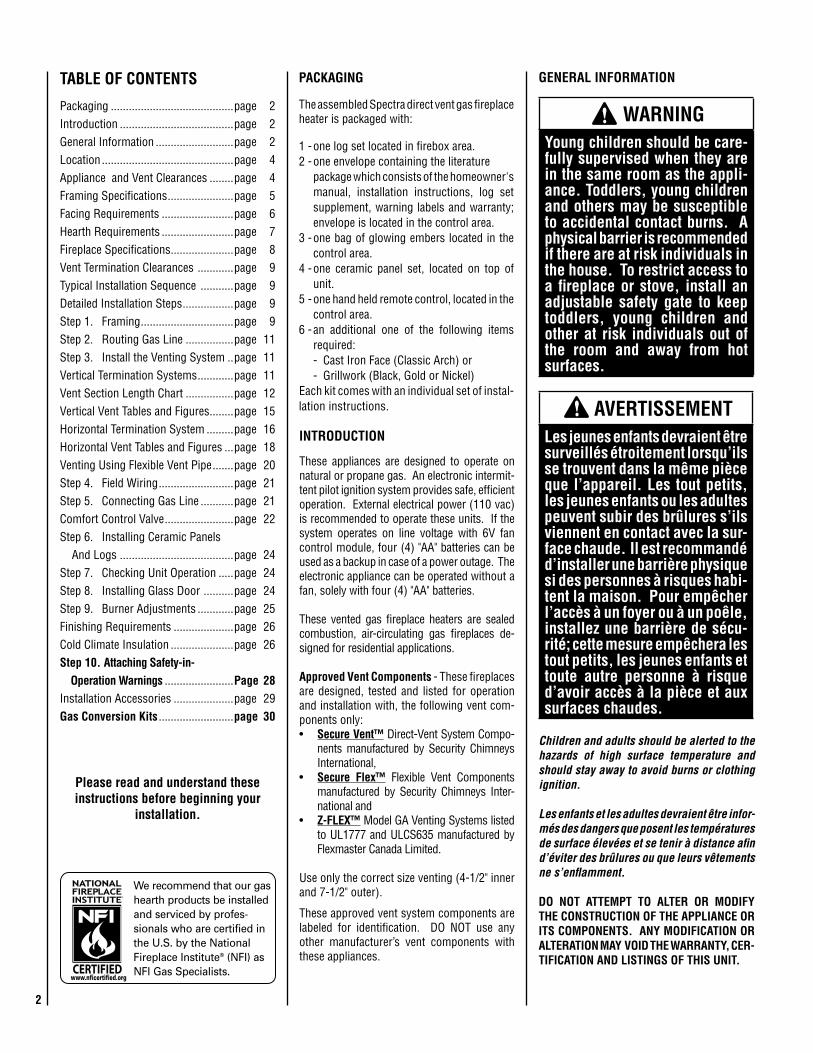
Children and adults should be alerted to the hazards of high surface temperature and should stay away to avoid burns or clothing ignition.
Les enfants et les adultes devraient être infor-més des dangers que posent les températures de surface élevées et se tenir à distance afin d’éviter des brûlures ou que leurs vêtements ne s’enflamment.
DO NOT ATTEMPT TO ALTER OR MODIFY THE CONSTRUCTION OF THE APPLIANCE OR ITS COMPONENTS. ANY MODIFICATION OR ALTERATION MAY VOID THE WARRANTY, CER-TIFICATION AND LISTINGS OF THIS UNIT.
WARNING Young children should be care-fully supervised when they are in the same room as the appli-ance. Toddlers, young children and others may be susceptible to accidental contact burns. A physical barrier is recommended if there are at risk individuals in the house. To restrict access to a fireplace or stove, install an adjustable safety gate to keep toddlers, young children and other at risk individuals out of the room and away from hot surfaces.
AVERTISSEMENT Les jeunes enfants devraient être surveillés étroitement lorsqu’ils se trouvent dans la même pièce que l’appareil. Les tout petits, les jeunes enfants ou les adultes peuvent subir des brûlures s’ils viennent en contact avec la sur-face chaude. Il est recommandé d’installer une barrière physique si des personnes à risques habi-tent la maison. Pour empêcher l’accès à un foyer ou à un poêle, installez une barrière de sécu-rité; cette mesure empêchera les tout petits, les jeunes enfants et toute autre personne à risque d’avoir accès à la pièce et aux surfaces chaudes.
GENERAL INFORMATION
These appliances are designed to operate on natural or propane gas. An electronic intermit-tent pilot ignition system provides safe, efficient operation. External electrical power (110 vac) is recommended to operate these units. If the system operates on line voltage with 6V fan control module, four (4) "AA" batteries can be used as a backup in case of a power outage. The electronic appliance can be operated without a fan, solely with four (4) "AA" batteries.
These vented gas fireplace heaters are sealed combustion, air-circulating gas fireplaces de-signed for residential applications.
Approved Vent Components - These fireplaces are designed, tested and listed for operation and installation with, the following vent com-ponents only:• Secure Vent™ Direct-Vent System Compo-
nents manufactured by Security Chimneys International,
• Secure Flex™ Flexible Vent Components manufactured by Security Chimneys Inter-national and
• Z-FLEX™ Model GA Venting Systems listed to UL1777 and ULCS635 manufactured by Flexmaster Canada Limited.
Use only the correct size venting (4-1/2" inner and 7-1/2" outer).
These approved vent system components are labeled for identification. DO NOT use any other manufacturer’s vent components with these appliances.
TABLE OF CONTENTS
Packaging .........................................page 2Introduction ......................................page 2General Information ..........................page 2Location ............................................page 4Appliance and Vent Clearances ........page 4Framing Specifications ......................page 5Facing Requirements ........................page 6Hearth Requirements ........................page 7Fireplace Specifications .....................page 8Vent Termination Clearances ............page 9Typical Installation Sequence ...........page 9Detailed Installation Steps .................page 9Step 1. Framing ...............................page 9Step 2. Routing Gas Line ................page 11Step 3. Install the Venting System ..page 11Vertical Termination Systems ............page 11Vent Section Length Chart ................page 12Vertical Vent Tables and Figures ........page 15Horizontal Termination System .........page 16Horizontal Vent Tables and Figures ...page 18Venting Using Flexible Vent Pipe .......page 20Step 4. Field Wiring .........................page 21Step 5. Connecting Gas Line ...........page 21Comfort Control Valve .......................page 22Step 6. Installing Ceramic Panels And Logs ......................................page 24Step 7. Checking Unit Operation .....page 24Step 8. Installing Glass Door ..........page 24Step 9. Burner Adjustments ............page 25Finishing Requirements ....................page 26Cold Climate Insulation .....................page 26Step 10. Attaching Safety-in- Operation Warnings .......................Page 28Installation Accessories ....................page 29Gas Conversion Kits .........................page 30
PACKAGING
The assembled Spectra direct vent gas fireplace heater is packaged with:
1 - one log set located in firebox area.2 - one envelope containing the literature
package which consists of the homeowner's manual, installation instructions, log set supplement, warning labels and warranty; envelope is located in the control area.
3 - one bag of glowing embers located in the control area.
4 - one ceramic panel set, located on top of unit.
5 - one hand held remote control, located in the control area.
6 - an additional one of the following items required:
- Cast Iron Face (Classic Arch) or - Grillwork (Black, Gold or Nickel)Each kit comes with an individual set of instal-lation instructions.
Please read and understand these instructions before beginning your
installation.
INTRODUCTION

3
Table 2
WARNING Improper installation, adjust-ment, alteration, service or maintenance can cause injury or property damage. Refer to this manual. For assistance or additional information consult a qualified installer, service agency or the gas supplier.
WARNING Failure to comply with these installation instructions will result in an improperly installed and operating appliance, voiding its warranty. Any change to this appli-ance and/or its operating controls is dangerous.
WARNING Clothing or other flammable material should not be placed on or near the appliance.
AVERTISSEMENT On ne devrait pas placer de vêtements ni d’autres matières inflammables sur l’appareil ni à proximité.
WARNING Any safety screen or guard removed for servicing the appli-ance must be replaced prior to operating the appliance.
AVERTISSEMENT Tout écran ou protecteur retiré pour permettre l’entretien de l’appareil doit être remis en place avant de mettre l’appareil en marche.
Note: Installation and repair should be done by a qualified service person. The appliance should be inspected before use and at least annually by a professional service person. More frequent cleaning may be required due to excessive lint from carpeting, bed-ding material, etcetera. It is imperative that control compartments, burners and circulating air passageways of the appliance be kept clean.
Remarque : L’installation et la réparation devrait être confiées à un technicien qualifié. L’appareil devrait faire l’objet d’une inspec-tion par un technicien professionnel avant d’être utilisé et au moins une fois l’an par la suite. Des nettoyages plus fréquents peuvent être nécessaires si les tapis, la literie, et cetera produisent une quantité importante de pous-sière. Il est essentiel que les comparti-ments abritant les commandes, les brûleurs et les conduits de circulation d’air de l’appareil soient tenus propres.
Do not use these appliances if any part has been under water. Immediately call a qualified, professional service technician to inspect the appliance and to replace any parts of the control system and any gas control which have been under water.
Ne pas utiliser cet appareil s’il a été plongé, même partiellement, dans l’eau. Ap-peler un technicien qualifié pour inspecter l’appareil et remplacer toute partie du système de commande et toute commande qui a été plongée dans l’eau.
Only trim kit(s) supplied by the manufacturer shall be used in the installation of this ap-pliance.
Seules les trousses de garniture fournies par le fabricant doivent être utilisées pour l’installation de cet appareil.
These appliances comply with National Safety Standards and are tested and listed by OMNI-Test Laboratories, Inc. (Report No. 116-F-02-5) to ANSI Z21.88 (in Canada, CSA-2.33), and CAN/CGA-2.17-M91 in both USA and Canada, as vented gas fireplace heaters.
Both millivolt and electronic versions of these appliances are listed by OMNI-Test Laboratories for installation in bedrooms and Manufactured Homes.
WARNING Improper installation or use of this appliance can cause serious injury or death from fire, burns, explosions or carbon monoxide poisoning.
Misc. Codes / Standards -The Installation must conform to local codes or, in the absence of local codes, with the National Fuel Gas Code, ANSI Z223.1/NFPA 54 - latest edition (In Canada, the current CAN/CSA-B149.1 installation code).
The appliance, when installed, must be electri-cally grounded and wired in accordance with local codes or, in the absence of local codes, with the National Electrical Code, ANSI/NFPA 70 - latest edition, or the Canadian Electrical Code, CSA C22.1 - latest edition.
Provide adequate clearances around air open-ings and adequate accessibility clearance for service and proper operation. Never obstruct the front or back openings of the appliance.
These appliances are designed to operate on natural or propane gas only. The use of other fuels or combination of fuels will degrade the performance of this system and may be dangerous.
These fireplaces are designed as supplemental heaters. Therefore, it is advisable to have an alternate primary heat source when installed in a dwelling. Refer to Table 1 for efficiencies.
Efficiencies %
ModelsNatural Gas Propane
P4* Steady State
AFUE**
P4* Steady State
AFUE**
LSS-35 51.6 73 70 53.6 73 71
LSS-40 58.8 73 70 61.7 73 71
Table 1*Canadian Energuide Rating**Annual Fuel Utilization Efficiency (AFUE) is the recognized U.S. rating system for the total efficiency of heating products.
These electronic models come standard with a mondulating gas valve; flame appearance and heat output can be controlled with the remote. The BTU Input for these appliances is shown in Table 2.
ledoM leuFmumixaM
tupnI)H/UTB(
muminiMtupnI
)H/UTB(
NC53-SSL saG.taN 000,33 005,32
PC53-SSL saGPL 000,13 005,32
NC04-SSL saG.taN 005,14 004,82
PC04-SSL saGPL 000,93 007,03

4 NOTE: DIAGRAMS & ILLUSTRATIONS ARE NOT TO SCALE.
Test gauge connections are provided on the front of the gas control valve (identified IN for the inlet and OUT for the manifold side). The control valves have a 3/8" (10mm) NPT thread inlet and outlet side of the valve (see Figure 1).
Propane tanks are at pressures that will cause damage to valve components. Verify that the tanks have step down regulators to reduce the pressure to safe levels.
Manifold Gas Supply Pressure(all models)
Fuel # Low High
Natural Gas
(Lo) 2.2" WC(0.55 kPa)
(Hi) 3.5" WC(0.87 kPa)
Propane (Lo) 6.3" WC(1.57 kPa)
(Hi) 10.0" WC(2.49 kPa)
Table 4
Burner Orifice Sizes Elevation 0-4500 feet ( 0-1372 meters)
ModelSeries
Nat.Gasdrill size (inches)
Propanedrill size (inches)
LSS-35 Rear Burner
#44 (0.086")*60J80•
#55 (0.052")*19L52•
LSS-35 Front Burner
#50 (0.070")*H4873•
#61 (0.039")*35M91•
LSS-40 Rear Burner
#42 (0.094")*H3721•
(0.054")*88J59•
LSS-40 Front Burner
#45 (0.082")*39L66•
#56 (0.047")*62L37•
Table 5
REQUIREMENTS FOR THE COMMON-WEALTH OF MASSACHUSETTS
These fireplaces are approved for installation in the US state of Massachusetts if the following additional requirements are met:• Install this appliance in accordance with
Massachusetts Rules and Regulations 248 C.M.R.
• Installationandrepairmustbedonebyaplumber or gas fitter licensed in the Com-monwealth of Massachusetts.
• Theflexiblegas lineconnectorusedshallnot exceed 36 inches (92 centimeters) in length.
• The individualmanual shut-offmustbeaT-handle type valve.
Massachusetts Horizontal Vent Requirements
In the Commonwealth of Massachusetts, hori-zontal terminations installed less than seven (7) feet above the finished grade must comply with the following additional requirements:
Inlet Gas Supply Pressure (all models)
Fuel # Minimum Maximum
Natural Gas 4.5" WC(1.12 kPa)
10.5" WC(2.61 kPa)
Propane 11.0" WC(2.74 kPa)
13.0" WC(3.23 kPa)
Table 3
Gas Pressure - All Models
Tables 3 and 4 show the appliances' inlet and manifold gas pressure requirements:
Gas Valve
Refer to Figure 1 for key gas valve features.
Orifice Sizes - Sea Level to High Altitude(All Models)
These appliances are tested and approved for installation at elevations of 0-4500 feet (0-1372 meters) above sea level using the standard burner orifice sizes (marked with an "*" in Table 5).
For elevations above 4500 feet, contact your gas supplier or qualified service technician .
Deration - At higher elevations, the amount of BTU fuel value delivered must be reduced by either:•Usinggasthathasbeenderatedbythegascompany.•Bychangingtheburnerorificetoasmallersize as regulated by the local authorities having jurisdiction and by the (USA) National Fuel Gas Code NFPA 54/ANSI Z223.1 - latest edition or, in Canada, the CAN/CSA-B149.1 codes - latest edition.
Install the appliance according to the regulations of the local authorities having jurisdiction and, in the USA, the National Fuel Gas Code NFPA 54 / ANSI Z223.1 - latest edition or, in Canada, the CAN/CSA-B149.1 - latest edition.
Flame breadth, height and width will diminish 4% for every 1,000 feet of altitude.
These appliances must be isolated from the gas supply piping system (by closing their individual manual shut-off valve) during any pressure testing of the gas supply piping system at test pressures equal to or less than 1/2 psig (3.5 kPa).
These appliances and their individual shut-off valves must be disconnected from the gas supply piping system during any pressure testing of that system at pressures greater than 1/2 psig (3.5 kPa).
These appliances must not be connected to a chimney or flue serving a separate solid fuel burning appliance.
Figure 1 SIT Proflame Valve
Orange Wire(From DFC Wire
Harness)
Pressure Regulator Tower
Yellow Ground Wire(From DFC Wire Harness)
Green Wire(From DFC Wire
Harness)
Line (In) Test Port
Manifold (Out) Test Port
Connect GTMS Wire Harness
* Standard size installed at factory• Part /Cat. Number
5NOTE: DIAGRAMS & ILLUSTRATIONS ARE NOT TO SCALE.
• A hard wired carbon monoxide detectorwith an alarm and battery back-up must be installed on the floor level where the gas fireplace is installed. The carbon monoxide detector must comply with NFPA 720, be ANSI/UL 2034 listed and be ISA certified.
• Ametalorplasticidentificationplatemustbe permanently mounted to the exterior of the building at a minimum height of eight (8) feet above grade and be directly in line with the horizontal termination. The sign must read, in print size no less than one-half (1/2) inch in size, GAS VENT DIRECTLY BELOW. KEEP CLEAR OF ALL OBSTRUCTIONS.
NEW YORK CITY, NEW YORK (MEA)
Installation of these fireplaces are approved for installation in New York City in the US state of New York.
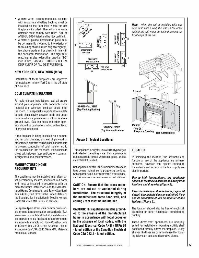
COLD CLIMATE INSULATION
For cold climate installations, seal all cracks around your appliance with noncombustible material and wherever cold air could enter the room. It is especially important to insulate outside chase cavity between studs and under floor on which appliance rests, if floor is above ground level. Gas line holes and other open-ings should be caulked or stuffed with unfaced fiberglass insulation.
If the fireplace is being installed on a cement slab in cold climates, a sheet of plywood or other raised platform can be placed underneath to prevent conduction of cold transferring to the fireplace and into the room. It also helps to sheetrock inside surfaces and tape for maximum air tightness and caulk firestops.
MANUFACTURED HOME REQUIREMENTS
This appliance may be installed in an aftermar-ket permanently located, manufactured home and must be installed in accordance with the manufacturer's instructions and the Manufac-tured Home Construction and Safety Standard, Title 24 CFR, Part 3280, in the United States, or the Standard for Installation in Mobile Homes, CAN/CSA Z240 MH Series, in Canada.
Cet appareil peut être installé cómme du matéri-el d'origine dans une maison préfabriquée (É.U. seulement) ou mobile et doit être installé selon les instructions du fabricant et conformément à la norme Manufactured Home Constructions and Safety, Title 24 CFR, Part 3200 aux Unis ou à la norme Can/CSA-Z240 Série MM, Maisons mobiles au Canada.
Figure 2 - Typical Locations
NOITACILPPA
TNEVPOT
APPLICATIONTOP VENT
TNEVPOT
NOITACILPPA
RECESSEDINSTALLATION
TOP VENT APPLICATION
NOITACILPPATNEV
POTNOITACILPPA
TNEVPOT
HORIZONTAL VENT(Top Vent Application)
VERTICAL VENT(Top Vent Application)
Note: When the unit is installed with one side flush with a wall, the wall on the other side of the unit must not extend beyond the front edge of the unit.
LOCATION
In selecting the location, the aesthetic and functional use of the appliance are primary concerns. However, vent system routing to the exterior and access to the fuel supply are also important.
Due to high temperatures, the appliance should be located out of traffic and away from furniture and draperies (Figure 2).
En raison des températures élevées, l’appareil devrait être installé dans un endroit où il y a peu de circulation et loin du mobilier et des tentures (Figure 2).
The location should also be free of electrical, plumbing or other heating/air conditioning ducting.
These direct-vent appliances are uniquely suited for installations requiring a utility shelf positioned directly above the fireplace. Utility shelves like these are commonly used for locat-ing television sets and decorative plants.
This appliance is only for use with the type of gas indicated on the rating plate. This appliance is not convertible for use with other gases, unless a certified kit is used.
Cet appareil doit être utilisé uniquement avec le type de gaz indiqué sur la plaque signalétique. Cet appareil ne peut être converti à d'autres gaz, sauf si une trousse de conversion est utilisée.
CAUTION: Ensure that the cross mem-bers are not cut or weakened during installation. The structural integrity of the manufactured home floor, wall, and ceiling / roof must be maintained.
CAUTION: This appliance must be ground-ed to the chassis of the manufactured home in accordance with local codes or in the absence of local codes, with the National Electrical Code ANSI / NFPA 70 - latest edition or the Canadian Electrical Code CSA C22.1 - latest edition.
Drywall
Mantel
Non-Combustible
Top OfFireplace Opening
6 NOTE: DIAGRAMS & ILLUSTRATIONS ARE NOT TO SCALE.
12 X
Roof Pitch is X/12
2 FT MIN. 2 FT MIN. Lowest
Discharge Opening
H*
*H = MINIMUM HEIGHT FROM ROOF TO LOWEST DISCHARGE OPENING OF VENT
TERMINATION HEIGHTS FOR VENTS ABOVE FLAT OR SLOPED ROOFS
Horizontal Overhang
Vertical Wall
Vent Termination
Storm Collar
Concentric Vent Pipe
Flashing
1 inch (25.4 mm) Minimum Clearance to Combustibles
Figure 4
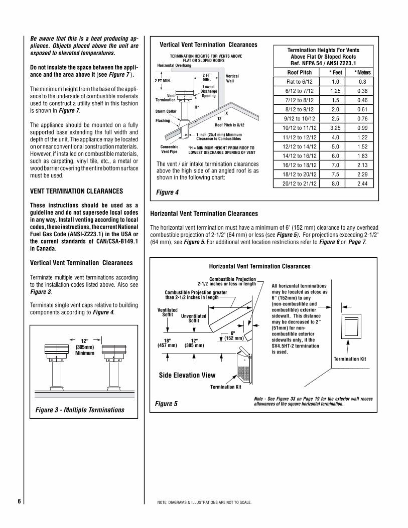
Vertical Vent Termination Clearances
VENT TERMINATION CLEARANCES
These instructions should be used as a guideline and do not supersede local codes in any way. Install venting according to local codes, these instructions, the current National Fuel Gas Code (ANSI-Z223.1) in the USA or the current standards of CAN/CSA-B149.1 in Canada.
Vertical Vent Termination Clearances
Terminate multiple vent terminations according to the installation codes listed above. Also see Figure 3.
Terminate single vent caps relative to building components according to Figure 4.
Note - See Figure 33 on Page 19 for the exterior wall recess allowances of the square horizontal termination.
Termination Heights For Vents Above Flat Or Sloped RoofsRef. NFPA 54 / ANSI Z223.1
Roof Pitch * Feet * Meters
Flat to 6/12 1.0 0.3
6/12 to 7/12 1.25 0.38
7/12 to 8/12 1.5 0.46
8/12 to 9/12 2.0 0.61
9/12 to 10/12 2.5 0.76
10/12 to 11/12 3.25 0.99
11/12 to 12/12 4.0 1.22
12/12 to 14/12 5.0 1.52
14/12 to 16/12 6.0 1.83
16/12 to 18/12 7.0 2.13
18/12 to 20/12 7.5 2.29
20/12 to 21/12 8.0 2.44
The vent / air intake termination clearances above the high side of an angled roof is as shown in the following chart:
Figure 5
6"(152 mm)12"
(305 mm)
Combustible Projection greater
Horizontal Vent Termination Clearances
Combustible Projection2-1/2 inches or less in length
18"(457 mm)
VentilatedSoffit Unventilated
Soffit
than 2-1/2 inches in length
Termination Kit
Side Elevation View
Termination Kit
All horizontal terminationsmay be located as close as6” (152mm) to any(non-combustible andcombustible) exteriorsidewall. This distancemay be decreased to 2”(51mm) for non--combustible exteriorsidewalls only, if theSV4.5HT-2 terminationis used.
Horizontal Vent Termination Clearances
The horizontal vent termination must have a minimum of 6" (152 mm) clearance to any overhead combustible projection of 2-1/2" (64 mm) or less (see Figure 5). For projections exceeding 2-1/2" (64 mm), see Figure 5. For additional vent location restrictions refer to Figure 6 on Page 7.
12”(305mm)Minimum
Figure 3 - Multiple Terminations
Be aware that this is a heat producing ap-pliance. Objects placed above the unit are exposed to elevated temperatures.
Do not insulate the space between the appli-ance and the area above it (see Figure 7 ).
The minimum height from the base of the appli-ance to the underside of combustible materials used to construct a utility shelf in this fashion is shown in Figure 7.
The appliance should be mounted on a fully supported base extending the full width and depth of the unit. The appliance may be located on or near conventional construction materials. However, if installed on combustible materials, such as carpeting, vinyl tile, etc., a metal or wood barrier covering the entire bottom surface must be used.

7NOTE: DIAGRAMS & ILLUSTRATIONS ARE NOT TO SCALE.
EXTERIOR HORIZONTAL VENT TERMINATION CLEARANCE REQUIREMENTS
Figure 6
V
VV
V
V
F
C
FixedClosedWindow
OperableWindow
B
B
A
B
H
M
I
= Area where Termination is not Permitted= Air Supply InletX = Vent TerminationV
D
V
3 ft.
3 ft.
A A
A = 9” in U.S.= 12” in Canada
VL
B
J
X
V
A
G
InsideCorner Detail
BC
C
C
*18”
Ventilated Soffit
HorizontalTermination
Detail D
Exterior Wall
6”
Inside Corner
* See Item D in the Text Below.
V
P
V
O
N N
Q
NOTE: Local Codes Or RegulationsMay Require Different Clearances.
NOTE: Location Of The Vent TerminationMust Not Interfere With Access To TheElectrical Service.
E
*noitallatsnInaidanaC **noitallatsnISU.ynoclabro,kced,hcrop,adnarev,edargevobaecnaraelC=A *)mc03(sehcni21 **)mc03(sehcni21
.denepoebyamtahtroodrowodniwotecnaraelC=B secnailpparof)mc51(sehcni6)mc03(sehcni21,)Wk3(hutB000,01<
)Wk3(hutB000,01>secnailpparof
secnailpparof)mc51(sehcni6)mc32(sehcni9,)Wk3(hutB000,01<
dna)Wk3(hutB000,01>secnailpparof)mc03(sehcni21,)Wk51(hutB000,05<
**)Wk51(hutB000,05>secnailpparof
wodniwdesolcyltnenamrepotecnaraelC=C otdednemmocer)mm503(sehcni21noitasnednocwodniwtneverp
otdednemmocer)mm922(sehcni9noitasnednocwodniwtneverp
ehtevobadetacoltiffosdetalitnevotecnaraelclacitreV=D)mm854(sehcni81foecnatsidlatnozirohanihtiwnoitanimret
noitanimretehtfoenilretnecehtmorf
)mm854(sehcni81 )mm854(sehcni81
***tiffosdetalitnevnuotecnaraelC=E )mm503(sehcni21 )mm503(sehcni21renrocedistuootecnaraelC=F muminim)mc7.21(sehcni5 muminim)mc7.21(sehcni5
renrocedisniotecnaraelC=G 2-TH5.4VS-muminim)mc80.5(sehcni2 2-TH5.4VS-muminim)mc80.5(sehcni2evobadednetxeenilretnecfoedisnihcaeotecnaraelC=H
ylbmessarotaluger/retemteef51fothgiehanihtiw)mc19(teef3
*ylbmessarotaluger/retemehtevobateef51fothgiehanihtiw)mc19(teef3
**ylbmessarotaluger/retemehtevobateltuotnevrotalugerecivresotecnaraelC=I *)mc19(teef3 **)mc19(teef3
rognidliubottelniylppusrialacinahcemnonotecnaraelC=Jecnailpparehtoynaottelnirianoitsubmoceht
secnailpparof)mc51(sehcni6)mc03(sehcni21,)Wk3(hutB000,01<
)Wk3(hutB000,01>secnailpparof
secnailpparof)mc51(sehcni6)mc32(sehcni9,)Wk3(hutB000,01<
dna)Wk3(hutB000,01>secnailpparof)mc03(sehcni21,)Wk51(hutB000,05<
**)Wk51(hutB000,05>secnailpparoftelniylppusrialacinahcemaotecnaraelC=K *)m38.1(teef6 teef01nihtiwfievoba)mc19(teef3
**yllatnoziroh)m3(detacolyaweviddevaproklawedisdevapevobaecnaraelC=L
ytreporpcilbupno‡)m31.2(teef7 ‡)m31.2(teef7
ynoclabrokced,hcrop,adnarevrednuecnaraelC=M ‡*)mc03(sehcni21 ‡)mc03(sehcni21)mumixaM(evoclAfohtpeD=N *)m38.1(teef6 **)m38.1(teef6
)evoclA(noitanimreTotecnaraelC=O *)mm2.51(sehcni6 **)mm2.51(sehcni6)muminiM(evoclAfohtdiW=P *)mc19(teef3 *)mc19(teef3
)evoclA(evobAelbitsubmoCotecnaraelC=Q *)mm754(sehcni81 **)mm754(sehcni81.edoCnoitallatsnIenaporPdnAsaGlanoitaN1.941B-ASCtnerrucehthtiwecnadroccanI*
.sedoCsaGleuFlanoitaN45APFN/1.322ZSISNAtnerucehthtiwecnadroccanI**.muminim)mc67(sehcni03-lairetamtiffoslynivotderiuqerecnaraelC***
htobsevresdnasgnillewdylimafelgnisowtneewtebdetacolsihcihwyawevirddevaproklawedisaevobayltceridetanimrettonllahstnevA‡.sgnillewd
.roolfehthtaenebsedis2muminimanonepoyllufsiynoclabrokced,hcrop,adnarevfidettimrepylnO‡*

8 NOTE: DIAGRAMS & ILLUSTRATIONS ARE NOT TO SCALE.
5 (127)
8-1/4(209)
14(356)
12 (305)
17 (431)
2(51)
4(102)
6(152)
8(203)
10(254)
12(305)
18 (457)
22 (559)
26 (660)
24 (610)
20 (508)
Top OfFireplaceOpening
16 (406)
inches (millimeters)Mantel Depth
Figure 8 - Minimum Mantel Clearances
Figure 9 - Minimum Distance to Unprotected Side Wall
Top View of Fireplace
45o
Protected wall shown in white
Inches (millimeters)
MINIMUM CLEARANCES TO COMBUSTIBLES
Appliance And Vent Clearances
The appliance is approved with zero clearance to combustible materials on all sides (as detailed in Table 6 ), with the following exception: When the unit is installed with one side flush with a wall, the wall on the other side of the unit must not extend beyond the front edge of the unit. In addition, when the unit is recessed, the side walls surrounding the unit must not extend beyond the front edge of the unit (see Figure 2).
*Note: 3 in. (76 mm) above any horizontal/inclined vent component.
**Note: See Page 9, Step 1 for clearance requirements to the nailing flange located at each side of the unit and any screw heads adjacent to it.
Hearth Extension - A hearth extension is not required with this appliance. If a hearth extension is used, do not block the lower control compartment door. Any hearth extension used is for appearance only and does not have to conform to standard hearth extension installation requirements.
Shelf Height - To provide for the lowest possible shelf surface, the venting attached to the top vent should be routed in a way to minimize obstructions to the space above the appliance. Do not insulate the space between the appliance and the area above it (see Figure 7). The minimum height from the base of the appliance to the underside of combustible materials used to construct a utility shelf in this fashion is shown in Figure 7.
Wall Finishes / Surrounds / MantelsNote: Combustible wall finish materials and/or surround materials must not be allowed to en-croach the area defined by the appliance front face (black sheet metal). Never allow combustible materials to be positioned in front of or overlapping the appliance face (see Figure 9 and Figure 50 on Page 34).
Non-combustible materials, such as surrounds and other appliance trim, may be installed on the appliance face with these exceptions: they must not cover any portion of the removable glass panel.
Vertical installation clearances to combustible mantels vary accord-ing to the depth of the mantel. See Figure 8. Mantels constructed of non-combustible materials may be installed at any height above the appliance opening; however, do not allow anything to hang below the fireplace hood.
Combustible materials may project beyond one side of the fireplace opening as long as they are kept within the shaded areas illustrated here.
Combustible Materials Allowed In Shaded Area “Safe Zone”
Combustible Walls shown in dark gray
At 14" minimum side wall clearance, a combustible wall can project to any length.
At 8-1/4" side wall clearance, a combustible wall can project 12"
Figure 7 - Shelf Height Minimum Clearances With Top Venting
MINIMUM CLEARANCES* Inches (millimeters)
Back 1/2 in. (13) to wrapper0 (0) to Spacers
Sides 1/2 in. (13) to wrapper0 (0) to Spacers **
Top Spacers 0 (0)
Floor 0 (0)
From Bottom of Unit To Ceiling 64 (1626)
Vent 3 (76) Top* / 1 (25.4) Sides & Bottom
SERVICE CLEARANCES Feet (meters)
Front 3 feet (0.9 meters)
Table 6
.oNledoM)mm(sehcnithgieHflehS
woblEeergeD09enOhtiw-tneVpoT
tneVeruceS xelFeruceS53-SSL 2/175 )1641( 4/195 )5051(04-SSL )9941(95 )3451(4/306
Shelf Height(see table)
Do not insulate thespace between theappliance and the
area above it.
Shelf Above Fireplace With Top Venting
12-1/4”(311mm)
*Note: For Secure Vent A SV4.5L6 6” Section (Cat. No. 77L70) Is Required.
*See Note
9NOTE: DIAGRAMS & ILLUSTRATIONS ARE NOT TO SCALE.
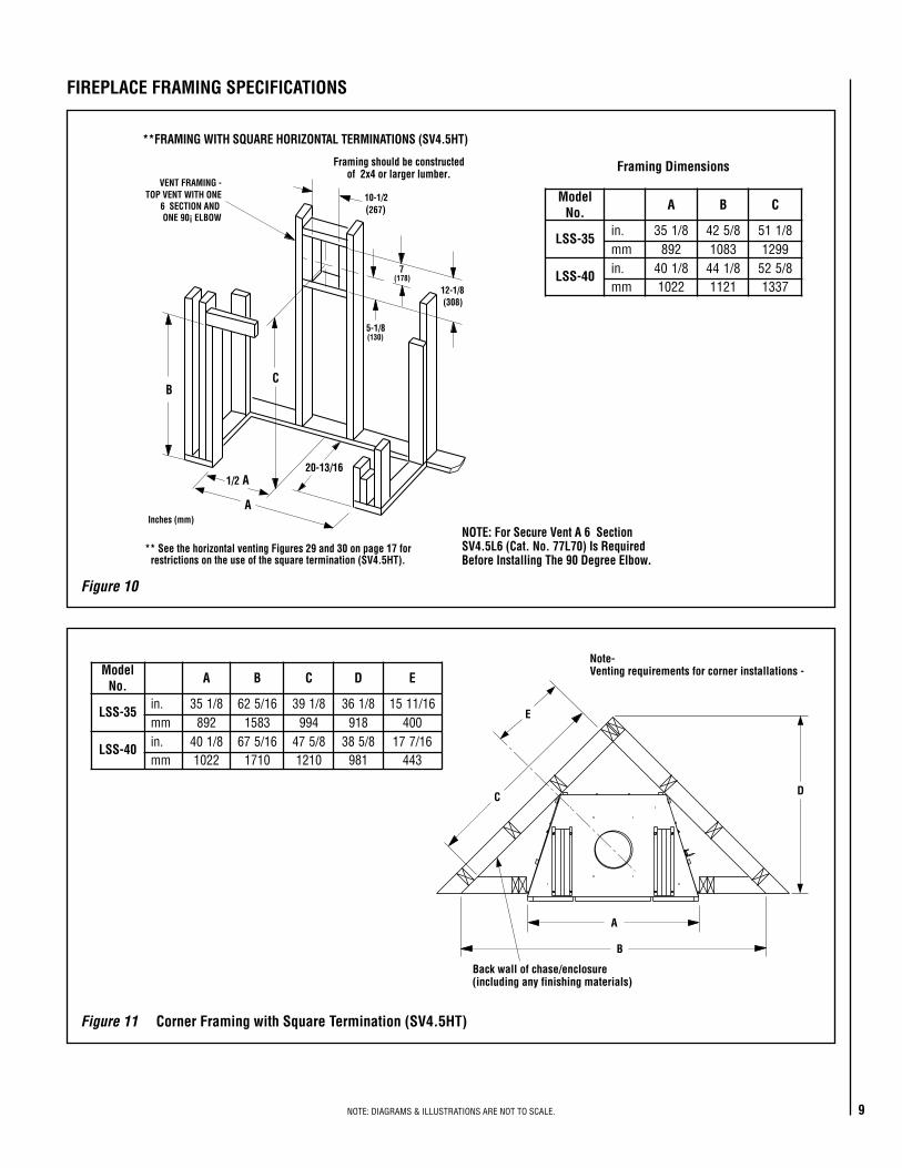
Figure 10
FIREPLACE FRAMING SPECIFICATIONS
A
B
7(178)
(308)
(267)
C
VENT FRAMING -TOP VENT WITH ONE
6 SECTION ANDONE 90¡ ELBOW
Framing should be constructedof 2x4 or larger lumber.
Inches (mm)
(130)
**FRAMING WITH SQUARE HORIZONTAL TERMINATIONS (SV4.5HT)
** See the horizontal venting Figures 29 and 30 on page 17 forrestrictions on the use of the square termination (SV4.5HT).
NOTE: For Secure Vent A 6 SectionSV4.5L6 (Cat. No. 77L70) Is RequiredBefore Installing The 90 Degree Elbow.
5-1/8
12-1/8
10-1/2
20-13/161/2 A
ledoM.oN A B C D E
53-SSL.ni 53 8/1 61/526 8/193 8/163 61/1151mm 298 3851 499 819 004
04-SSL .ni 8/104 61/576 8/574 8/583 61/771mm 2201 0171 0121 189 344
C
Back wall of chase/enclosure(including any finishing materials)
Note-Venting requirements for corner installations -
D
A
B
E
ledoM.oN A B C
53-SSL.ni 53 8/1 8/524 8/115mm 298 3801 9921
04-SSL .ni 8/104 8/144 8/525mm 2201 1211 7331
Framing Dimensions
Figure 11 Corner Framing with Square Termination (SV4.5HT)
10 NOTE: DIAGRAMS & ILLUSTRATIONS ARE NOT TO SCALE.
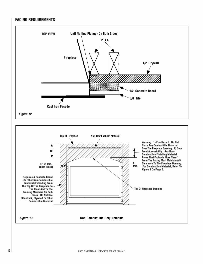
FACING REQUIREMENTS
Figure 13 Non-Combustible Requirements
Unit Nailing Flange (On Both Sides)
Cast Iron Facade
Fireplace
TOP VIEW
1/2 Drywall
3/8 Tile
1/2 Concrete Board
2 x 4
9Min.
Requires A Concrete Board(Or Other Non-Combustible
Material) Extending FromThe Top Of The Fireplace To
The Floor And To TheFraming Members On Both
Sides. Do Not UseSheetrock, Plywood Or Other
Combustible Material
4 1/2 Min.(Both Sides)
Top Of Fireplace Non-Combustible Material
Warning: 1) Fire Hazard: Do NotPlace Any Combustible MaterialOver The Fireplace Opening. 2) DoorFront Accessibility: Any Non-Combustible Finishing MaterialAreas That Protrude More Than 1From The Facing Must Maintain A 9Clearance To The Fireplace Opening. For Combustible Material, Refer ToFigure 9 On Page 8.
Top Of Fireplace Opening
10
Figure 12
11NOTE: DIAGRAMS & ILLUSTRATIONS ARE NOT TO SCALE.
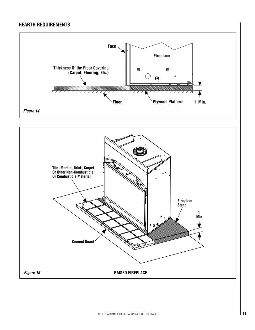
HEARTH REQUIREMENTS
Figure 14
Cement Board
Tile, Marble, Brick, Carpet,Or Other Non-CombustibleOr Combustible Material
FireplaceStand
1Min.
Figure 15 RAISED FIREPLACE
Fireplace
Floor Plywood Platform
Face
Thickness Of the Floor Covering(Carpet, Flooring, Etc.)
1 Min.
12 NOTE: DIAGRAMS & ILLUSTRATIONS ARE NOT TO SCALE.
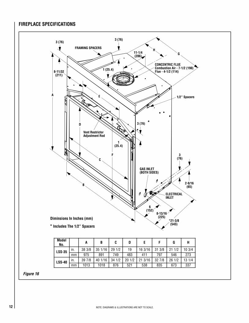
FIREPLACE SPECIFICATIONS
H
ELECTRICALINLET
Diminsions In Inches (mm)
* Includes The 1/2” Spacers
1 (25.4)
3 (76)
11-1/4(286)
G
1/2” Spacers
8-11/32(211)
A E
D
F
B
C
1(25.4)
3 (76)
GAS INLET(BOTH SIDES)
*21-3/8(543)
6(152)
8-13/16(225)
2-9/16(65)
3(76)
FRAMING SPACERS
CONCENTRIC FLUECombustion Air - 7-1/2 (190)Flue - 4-1/2 (114)
3 (76)
Vent RestrictorAdjustment Rod
ledoM.oN A B C D E F G H
53-SSL.ni 8/383 61/153 2/192 91 61/361 8/313 2/112 4/301mm 579 198 947 384 114 797 645 372
04-SSL .ni 8/793 61/104 2/143 2/102 61/312 8/723 2/162 4/131mm 3101 8101 678 125 835 538 376 733
Figure 16
13NOTE: DIAGRAMS & ILLUSTRATIONS ARE NOT TO SCALE.
DETAILED INSTALLATION STEPS
The appliance is shipped with all gas controls and components installed and pre-wired. Remove the shipping carton, exposing the front glass door. Remove ceramic panel kit from the top of the fireplace and set it aside with care. Remove the cardboard from underneath the pressure relief plates. Open the two latches (located under the firebox floor) securing the glass door. Remove the door by tilting it outward at the bottom and lifting it up. Set the door aside protecting it from inadvertent damage. See Figure 48 on page 27.
TYPICAL INSTALLATION SEQUENCE
The typical sequence of installation follows, however, each installation is unique resulting in variations to those described.
See the page numbers references in the follow-ing steps for detailed procedures.
Step 1. (page 13) Construct the appliance fram-ing. Position the appliance within the framing and secure with nailing brackets.Step 2. (page 13) Route gas supply line to appliance location.Step 3. (page 13) Install the vent system and exterior termination. Step 4. (page 23) Field Wiring Install the operating control switch (not factory provided) and bring in electrical service line for forced air circulating blower.Step 5. (page 23) Make connection to gas supply.Step 6. (page 26) Install the ceramic panel, logs, and glowing embers.Step 7. (page 26) Checkout appliance opera-tion. Step 8. (page 26) Install glass door frame assembly.Step 9. (page 27) Adjust burner to ensure proper flame appearance.Step 10. (page 28) Affix warning labels.
Step 1. FRAMING
Frame these appliances as illustrated in Figure 10 on page 9, unless the appliance is to be installed in a corner. See Figure 11 on page 9 for corner framing installations. All framing details must allow for a minimum clearance to combustible framing members as shown in Table 6 on page 8.
See Figure 12 on page 10 for the facing detail. See Figure 13 on page 10 for the Non-Com-bustible requirements. See Figures 14 and 15 on page 11 for Hearth Requirements.
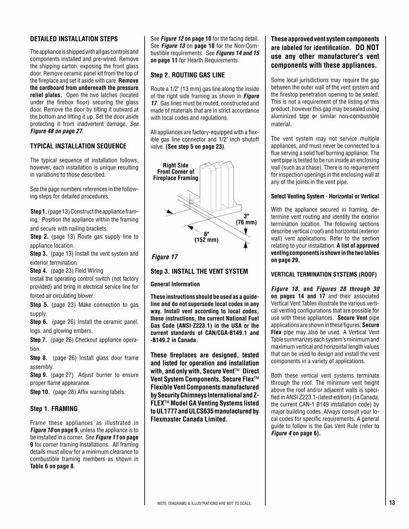
Right SideFront Corner of
Fireplace Framing
6"(152 mm)
3"(76 mm)
Figure 17
Step 3. INSTALL THE VENT SYSTEM
General Information
These instructions should be used as a guide-line and do not supersede local codes in any way. Install vent according to local codes, these instructions, the current National Fuel Gas Code (ANSI-Z223.1) in the USA or the current standards of CAN/CGA-B149.1 and -B149.2 in Canada.
These fireplaces are designed, tested and listed for operation and installation with, and only with, Secure Vent™ Direct Vent System Components, Secure Flex™ Flexible Vent Components manufactured by Security Chimneys International and Z-FLEX™ Model GA Venting Systems listed to UL1777 and ULCS635 manufactured by Flexmaster Canada Limited.
These approved vent system components are labeled for identification. DO NOT use any other manufacturer's vent components with these appliances.
Some local jurisdictions may require the gap between the outer wall of the vent system and the firestop penetration opening to be sealed. This is not a requirement of the listing of this product, however this gap may be sealed using aluminized tape or similar non-combustible material.
The vent system may not service multiple appliances, and must never be connected to a flue serving a solid fuel burning appliance. The vent pipe is tested to be run inside an enclosing wall (such as a chase). There is no requirement for inspection openings in the enclosing wall at any of the joints in the vent pipe.
Select Venting System - Horizontal or Vertical
With the appliance secured in framing, de-termine vent routing and identify the exterior termination location. The following sections describe vertical (roof) and horizontal (exterior wall) vent applications. Refer to the section relating to your installation. A list of approved venting components is shown in the two tables on page 29. VERTICAL TERMINATION SYSTEMS (ROOF)
Figure 18, and Figures 28 through 30 on pages 14 and 17 and their associated Vertical Vent Tables illustrate the various verti-cal venting configurations that are possible for use with these appliances. Secure Vent pipe applications are shown in these figures; Secure Flex pipe may also be used. A Vertical Vent Table summarizes each system’s minimum and maximum vertical and horizontal length values that can be used to design and install the vent components in a variety of applications.
Both these vertical vent systems terminate through the roof. The minimum vent height above the roof and/or adjacent walls is speci-fied in ANSI Z223.1-(latest edition) (In Canada, the current CAN-1 B149 installation code) by major building codes. Always consult your lo-cal codes for specific requirements. A general guide to follow is the Gas Vent Rule (refer to Figure 4 on page 6).
Step 2. ROUTING GAS LINE
Route a 1/2" (13 mm) gas line along the inside of the right side framing as shown in Figure 17. Gas lines must be routed, constructed and made of materials that are in strict accordance with local codes and regulations.
All appliances are factory-equipped with a flex-ible gas line connector and 1/2" inch shutoff valve. (See step 5 on page 23).

14 NOTE: DIAGRAMS & ILLUSTRATIONS ARE NOT TO SCALE.
Figure 18
Vertical (Offset) Installation
Analyze the vent routing and determine the quantities of vent sections and number of el-bows required. Refer to Vertical Vent Figures and Tables on page 17 to select the type of vertical installation desired. Vent sections are available in net lengths of 4-1/2" (114 mm), 10-1/2" (267 mm), 22-1/2" (572 mm), 34-1/2" (876 mm) and 46-1/2" (1181 mm). Refer to the Vent Section Length Chart on this page for an aid in selecting length combinations. Elbows are available in 90° and 45° configurations. Refer to Figure 23 for the SV4.5E45 and SV4.5E90 elbow dimensional specifications.
Vertical (Straight) Installation
Determine the number of straight vent sections required. 4-1/2" (114 mm), 10-1/2" (267 mm), 22-1/2" (572 mm), 34-1/2" (876 mm) and 46-1/2" (1181 mm) net section lengths are available. Plan the vent lengths so that a joint does not occur at the intersection of ceiling or roof joists. Refer to the Vent Section Length Chart on this page.
SV4.5CGV-1Termination SV4.5FA OR
SV4.5FB FlashingAND SV4.5SCSTORM COLLAR
*SV4.5VFFirestop/Spacer
SV4.5L6/12/24/36/48Vent Sections
60' Max(18.3 M)
1" (25.4 mm)MinimumClearance toCombustibles
*When using Secure Flex,use Firestop/Spacer
SF4.5VF
Note: Convert inches into metric equivalent measurement, as follows:
Millimeters (mm) = Inches x 25.4Centimeters (cm) = Inches x 2.54 Meters (M) = Inches x .0254
TRAHCHTGNELNOITCESTNEVlanimoN
htgneLnoitceS)sehcni(
6 21 42 63 84 TOTAL
QTY
noitceSteN)sehcni(htgneL 2/1-4 2/1-01 2/1-22 2/1-43 2/1-64
tneVfothgieH snoitceStneVforebmuN
sehcni tf
672 32 0 0 0 8 0 8
972 52.32 0 0 0 0 6 6
5.082 573.32 1 0 0 8 0 9
5.982 521.42 0 1 0 0 6 7
5.103 521.52 0 0 1 0 6 7
5.013 578.52 0 0 0 9 0 9
5.523 521.72 0 0 0 0 7 7
033 5.72 1 0 0 0 7 8
543 57.82 0 0 0 01 0 01
5.943 521.92 1 0 0 01 0 11
273 13 0 0 0 0 8 8
5.973 526.13 0 0 0 11 0 11
5.814 578.43 0 0 0 0 9 9
564 57.83 0 0 0 0 01 01
5.574 526.93 0 1 0 0 01 11
084 04 1 1 0 0 01 11
294 14 1 0 1 0 01 21
5.994 526.14 0 0 0 1 01 11
405 24 1 0 0 1 01 21
5.115 526.24 0 0 0 0 11 11
5.025 573.34 0 2 0 1 11 41
135 52.44 0 2 2 0 11 51
5.835 578.44 1 0 0 2 11 41
945 57.54 1 0 2 1 11 51
855 5.64 0 0 0 0 21 21
5.265 578.64 1 0 0 0 21 31
5.865 573.74 0 1 0 0 21 31
375 57.74 1 1 0 0 21 41
5.085 573.84 0 0 1 0 21 31
5.985 521.94 0 1 2 2 01 51
5.595 526.94 1 1 1 0 21 51
5.406 573.05 0 0 0 0 31 31
516 52.15 0 1 0 0 31 41
5.526 521.25 0 2 0 0 31 51
5.136 526.25 1 0 1 0 31 51
5.736 521.35 0 1 1 0 31 51
156 52.45 0 0 0 0 41 41
5.556 526.45 1 0 0 0 41 51
276 65 0 2 0 0 41 61
876 5.65 1 0 1 0 41 61
5.886 573.75 1 1 1 0 41 71
5.796 521.85 0 0 0 0 51 51
207 5.85 1 0 0 0 51 61
5.217 573.95 1 1 0 0 51 71
027 06 0 0 1 0 51 61
TRAHCHTGNELNOITCESTNEVlanimoN
htgneLnoitceS)sehcni(
6 21 42 63 84TOOOOOTTTTTAAAAALLLLL
QQQQQTTTTTYYYYY
noitceSteN)sehcni(htgneL 2/1-4 2/1-01 2/1-22 2/1-43 2/1-64
tneVfothgieH snoitceStneVforebmuN
sehcni tf
5.4 573.0 1 0 0 0 0 19 57.0 2 0 0 0 0 2
5.01 578.0 0 1 0 0 0 1
51 52.1 1 1 0 0 0 2
5.22 578.1 0 0 1 0 0 1
5.13 526.2 0 3 0 0 0 3
5.43 578.2 0 0 0 1 0 1
5.73 521.3 1 1 1 0 0 3
5.34 526.3 0 2 1 0 0 3
54 57.3 0 0 2 0 0 2
5.64 578.3 0 0 0 0 1 1
15 52.4 1 0 0 0 1 25.55 526.4 0 1 2 0 0 3
75 57.4 0 0 1 1 0 2
5.76 526.5 0 0 3 0 0 3
96 57.5 0 0 0 2 0 2
5.37 521.6 1 0 0 2 0 3
5.97 526.6 0 1 0 2 0 3
18 57.6 0 0 0 1 1 2
5.19 526.7 0 0 2 0 1 3
39 57.7 0 0 0 0 2 2
5.79 521.8 1 0 0 0 2 35.301 526.8 0 0 0 3 0 3
801 9 1 0 0 3 0 4711 57.9 1 0 5 0 0 6
5.811 578.9 1 1 0 3 0 5
621 5.01 0 0 1 3 0 4
5.031 578.01 1 0 1 3 0 5
531 52.11 0 0 6 0 0 6
5.931 526.11 0 0 0 0 3 3
5.241 578.11 1 0 0 4 0 5441 21 1 0 0 0 3 45.451 578.21 1 1 0 0 3 5
5.061 573.31 0 2 0 0 3 5
5.271 573.41 0 0 0 5 0 5
771 57.41 1 0 0 5 0 6
681 5.51 0 0 0 0 4 4
5.691 573.61 0 1 0 0 4 5
702 52.71 0 0 0 6 0 6
5.112 526.71 1 0 0 6 0 7
5.712 521.81 0 1 0 6 0 7
5.922 521.91 0 0 1 6 0 7
5.232 573.91 0 0 0 0 5 5
5.142 521.02 0 0 0 7 0 7
642 5.02 1 0 0 7 0 8
252 12 0 1 0 7 0 8

15NOTE: DIAGRAMS & ILLUSTRATIONS ARE NOT TO SCALE.
Figure 22
Support Straps(Plumber’s tape)
8 feet (2.4 m)Maximum
Blocking
Figure 21
Figure 20
Figure 19
B. Attach vent components to appliance - Secure Vent SV4.5 direct vent system compo-nents are unitized concentric pipe components featuring positive twist lock connections (see Figure 20 ).
All of the appliances covered in this document are fitted with collars having locking inclined channels. The dimpled end of the vent com-ponents fit over the appliance collar to create the positive twist lock connection.
First VentComponentAlign the dimple (four places)with the opening of the lockingincline channel on appliancecollar. Twist vent componentclockwise to engage and seal.
LockingIncline Channel
Dimple
Appliance collar
Vent / Appliance CollarConnection
Align the dimple (four places) of theupper vent section with the opening ofthe locking incline channel on thelower vent section. Twist ventcomponent clockwise to engage andseal until arrow and dimple align.
LockingIncline Channel
Dimple
ArrowConnected
Vent Sections
Vent / Vent SectionConnection
Arrow
Arrow
To attach a vent component to the appliance collar, align the dimpled end over the collar, adjusting the radial alignment until the four locking dimples are aligned with the inlet of the four inclined channels on the collar (refer to Figure 20 ). Push the vent component against the collar until it fully engages, then twist the component clockwise, running the dimples down and along the incline channels until they seat at the end of the channels.
The unitized design of the Secure Vent com-ponents will engage and seal both the inner and outer pipe without the need for sealant or screws. If desired, a #6 x 1/2" screw may be used at the joint, but is not required as the pipe will securely lock when twisted.
C. Attach vent components to each other - Other vent sections may be added to the pre-viously installed section in accordance with the requirements of the vertical vent figures and tables. To add another vent component to a length of vent run, align the dimpled end over the inclined channel end of the previously installed section, adjusting the radial alignment until the four locking dimples are aligned with the inlets of the four incline channels of the previous section.
10-1/2” Min.(267 mm)
10-1/2” Min.(267 mm)
Push the vent component against the previous section until it fully engages, then twist the component clockwise running the dimples down and along the incline channels until they seat at the end of the channels. This seating position is indicated by the alignment of the arrow and dimple as shown in Figure 21.
D. Install firestop/spacer at ceiling - When using Secure Vent, use SV4.5VF firestop/spacer at ceiling joists; when using Secure Flex, use SF4.5VF firestop/spacer. If there is living space above the ceiling level, the firestop/spacer must be installed on the bottom side of the ceiling. If attic space is above the ceiling, the firestop/spacer must be installed on the top side of the joist. Route the vent sections through the framed opening and secure the firestop/spacer with 8d nails or other appropriate fasteners at each corner.
Remember to maintain 1" (25 mm) clearance to combustibles, framing members, and attic or ceiling insulation when running vertical chimney sections.
E. Support the vertical vent run sections -Support the vertical portion of the venting system every 8 feet (2.4m) above the fireplace vent outlet using field provided support straps (conventional plumber's tape). Secure the plumber's tape to the framing members with nails or screws.
Loop the tape around the vent, securing the ends of the tape to the framing. If desired, sheet metal screws #6 x 1/2" length may be used to secure the support straps to the vent pipe . See Figure 22.
Where required, a telescopic vent section (SV4.5LA) may be used to provide the installer with an option in installing in tight and confined spaces or where the vent run made up of fixed length pieces develops a joint in a undesirable location, or will not build up to the required length. The SV4.5LA Telescopic Vent Section has an effective length of from 1-1/2" (38 mm) to 7-1/2" (191 mm). The SV4.5LA is fitted with a locking inclined channel end (identical to a normal vent section component) and a plain end with 3 pilot holes. Slip the plain end over the locking channel end of a standard SV4.5 vent component the required distance and secure with three screws.
Maintain a minimum 1" (25 mm) clearance to combustible materials for all vertical elements. Clearances for all horizontal elements are 3" (76 mm) on top, 1" (25 mm) on sides and 1" (25 mm) on the bottom.
A. Frame ceiling opening - Use a plumb line from the ceiling above the appliance to locate center of the vertical run. Cut and/or frame an opening, 10-1/2" x 10-1/2" (267mm x 267mm) inside dimensions, about this center mark (Figure 19 ).
16 NOTE: DIAGRAMS & ILLUSTRATIONS ARE NOT TO SCALE.
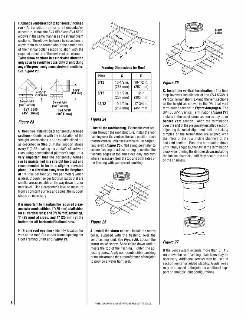
Figure 24
Figure 25
Figure 27
Figure 26
K. Install the vertical termination - The final step involves installation of the SV4.5CGV-1 Vertical Termination. Extend the vent sections to the height as shown in the "Vertical vent termination section" in Figure 4 on page 6. The SV4.5CGV-1 Vertical Termination (Figure 27 ) installs in the exact same fashion as any other Secure Vent section. Align the termination over the end of the previously installed section, adjusting the radial alignment until the locking dimples of the termination are aligned with the inlets of the four incline channels of the last vent section. Push the termination down until it fully engages, then twist the termination clockwise running the dimples down and along the incline channels until they seat at the end of the channels.
I. Install the roof flashing - Extend the vent sec-tions through the roof structure. Install the roof flashing over the vent section and position such that the vent column rises vertically (use carpen-ters level) (Figure 25 ). Nail along perimeter to secure flashing or adjust roofing to overlap the flashing edges at top and sides only and trim where necessary. Seal the top and both sides of the flashing with waterproof caulking.
If the vent system extends more than 5' (1.5 m) above the roof flashing, stabilizers may be necessary. Additional screws may be used at section joints for added stability. Guide wires may be attached to the joint for additional sup-port on multiple joint configurations.
G. Continue installation of horizontal/inclined sections - Continue with the installation of the straight vent sections in horizontal/inclined run as described in Step C. Install support straps every 5' (1.52 m) along horizontal/inclined vent runs using conventional plumber’s tape. It is very important that the horizontal/inclined run be maintained in a straight (no dips) and recommended to be in a slightly elevated plane, in a direction away from the fireplace of 1/4" rise per foot (20 mm per meter) which is ideal, though rise per foot run ratios that are smaller are acceptable all the way down to at or near level. Use a carpenter’s level to measure from a constant surface and adjust the support straps as necessary.
It is important to maintain the required clear-ances to combustibles: 1" (25 mm) at all sides for all vertical runs; and 3" (76 mm) at the top, 1" (25 mm) at sides, and 1" (25 mm) at the bottom for all horizontal/inclined runs.
H. Frame roof opening - Identify location for vent at the roof. Cut and/or frame opening per Roof Framing Chart and Figure 24.
J. Install the storm collar - Install the storm collar, supplied with the flashing, over the vent/flashing joint. See Figure 26. Loosen the storm collar screw. Slide collar down until it meets the top of the flashing. Tighten the ad-justing screw. Apply non-combustible caulking or mastic around the circumference of the joint to provide a water tight seal.
C
D
StormCollar
Figure 23
F. Change vent direction to horizontal/inclined run - At transition from or to a horizontal/in-clined run, install the SV4.5E45 and SV4.5E90 elbows in the same manner as the straight vent sections. The elbows feature a twist section to allow them to be routed about the center axis of their initial collar section to align with the required direction of the next vent run element. Twist elbow sections in a clockwise direction only so as to avoid the possiblity of unlocking any of the previously connected vent sections. See Figure 23.
SV4.5E90(90° Elbow)
7-5/8"(194 mm)
Swivel Joint(360° swivel)
4-13/16"(122 mm)
SV4.5E45(45° Elbow)
Swivel Joint(360° swivel)
Framing Dimensions for Roof
Pitch C D
0/12 10-1/2 in. 10-1/2 in. (267 mm) (267 mm)
6/12 10-1/2 in. 12 in. (267 mm) (305 mm)
12/12 10-1/2 in. 17-3/4 in. (267 mm) (451 mm)

17NOTE: DIAGRAMS & ILLUSTRATIONS ARE NOT TO SCALE.
Figure 28 - Top Vent - STRAIGHT
Figure 29 - Top Vent - TWO 90 DEGREE ELBOWS
VERTICAL VENT FIGURES/TABLES Note: Secure Vent (rigid vent pipe) is shown in the figures; Secure Flex (flexible vent pipe) may also be used.
Note: It is very important that the horizontal/inclined run be maintained in a straight (no dips) and recommended to be in a slightly elevated plane, in a direction away from the fireplace of 1/4" rise per foot (20 mm per meter) which is ideal, though rise per foot run ratios that are smaller are acceptable all the way down to at or near level.
Note: SV4.5VF (Secure Vent), SF4.5VF (Secure Flex) firestop/spacer must be used anytime vent pipe passes through a combustible floor or ceil-ing. SV4.5HF (Secure Vent), SF4.5HF (Secure Flex)firestop/spacer must be used anytime vent pipe passes through a combustible wall.
Note: Two 45 degree elbows may be used in place of one 90 degree elbow. The same rise to run ratios, as shown in the venting figures for 90 elbows, must be followed if 45 degree elbows are used.
AELBATV M MUMINI H mumixaM
teef )sretem( teef )sretem(
1* )503.0( 5 )25.1(
2 )016.0( 01 )1.3(
3 )419.0( 51 )56.4(
4 )22.1( 02 )2.6(
V+V 1 .xaM)m3.81(teef06=H+H .xaM)m2.6(teef02=
BELBAT
V M MUMINIH H+ 1
mumixaM
teef )m( teef )m(
1 )503.0( 5 )25.1(
2 )016.0( 01 )1.3(
3 )419.0( 51 )56.4(
4 )22.1( 02 )2.6(
H+H 1 .xaM)m2.6(teef02=V+V 1 H+H+ 1 teef06=
.xaM)m3.81(60 feet (18.3 meters)Maximum*Ceiling
Firestop/Spacer(SV4.5VF)
*When usingSecure Flex, useFirestop/Spacer
SF4.5VF
V
H1
H
V1
*CeilingFirestop/Spacer(SV4.5VF) **Wall
Firestop/Spacer(SV4.5HF)
*When using Secure Flex,use Firestop/Spacer
SF4.5VF
**When using SecureFlex, use Firestop/Spacer
SF4.5HF
*When developing chimney systems with horizontal runs (H) that end with a vertical run (V1), it is allowable to use an elbow attached directly to the top collar. Count the elbow attached to the collar as 1 foot of (V) run.
H
V
V1
*CeilingFirestop/Spacer
(SV4.5VF)
**WallFirestop/Spacer
(SV4.5HF)
**When using SecureFlex, use Firestop/Spacer
SF4.5HF
*When using Secure Flex,use Firestop/Spacer
SF4.5VF
Figure 30 - Top Vent - THREE ELBOWS
WARNING Under no circumstances may separate sections of concentric flexible vent pipe be joined together.
18 NOTE: DIAGRAMS & ILLUSTRATIONS ARE NOT TO SCALE.
VerticalRise
SV4.5E90Elbow
Horizontal / Inclined RunSV4.5 HTTermination
Firestop/Spacer
SV4.5L6/12/24/36/48Vent Sections
Support Bracket SpacingEvery 5 ft (1.52 m)
See Figure 19 on page 13 forvertical vent section support.
SV4.5 HTTermination
SupportBracketsBuilding
SupportFraming
Ceiling
Fireplace
ExteriorWall
ExteriorWall
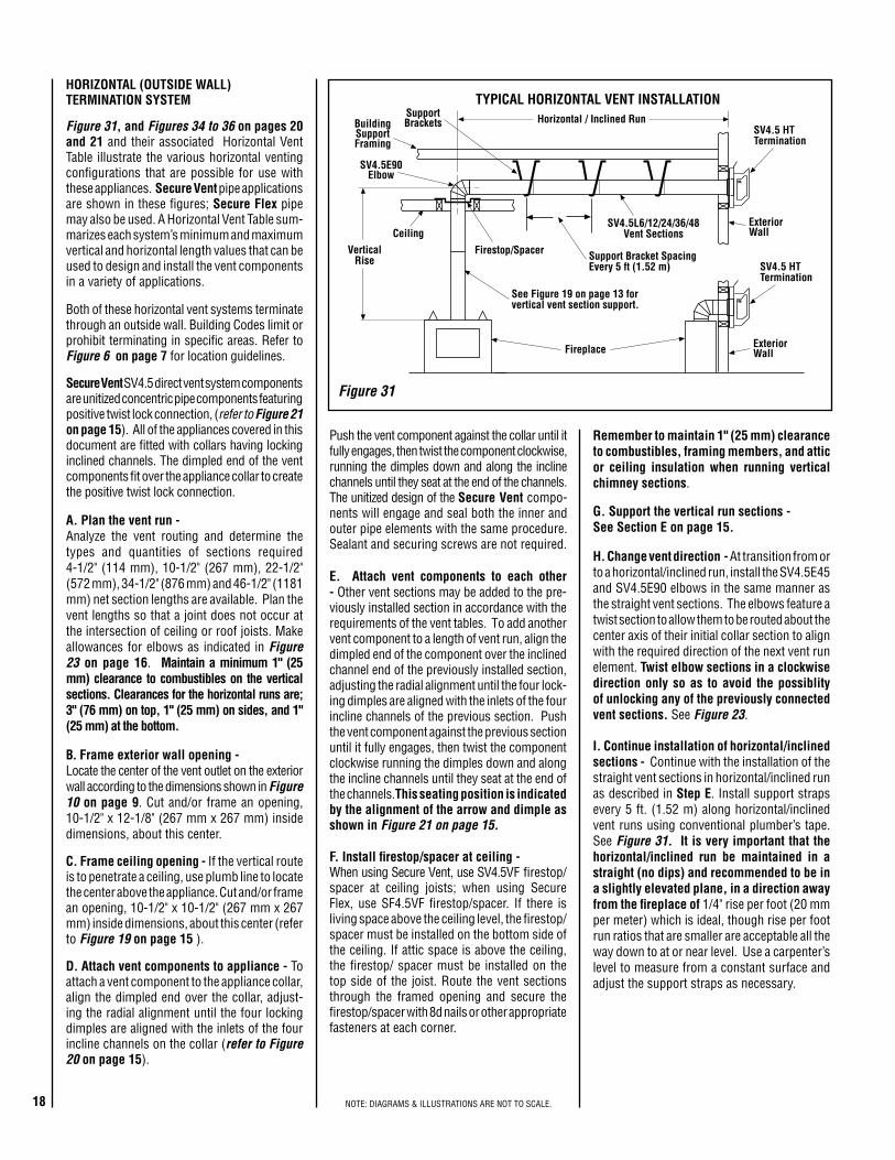
TYPICAL HORIZONTAL VENT INSTALLATION
Figure 31 Secure Vent SV4.5 direct vent system components are unitized concentric pipe components featuring positive twist lock connection, (refer to Figure 21 on page 15). All of the appliances covered in this document are fitted with collars having locking inclined channels. The dimpled end of the vent components fit over the appliance collar to create the positive twist lock connection.
A. Plan the vent run - Analyze the vent routing and determine the types and quantities of sections required 4-1/2" (114 mm), 10-1/2" (267 mm), 22-1/2" (572 mm), 34-1/2" (876 mm) and 46-1/2" (1181 mm) net section lengths are available. Plan the vent lengths so that a joint does not occur at the intersection of ceiling or roof joists. Make allowances for elbows as indicated in Figure 23 on page 16. Maintain a minimum 1" (25 mm) clearance to combustibles on the vertical sections. Clearances for the horizontal runs are; 3" (76 mm) on top, 1" (25 mm) on sides, and 1" (25 mm) at the bottom.
B. Frame exterior wall opening - Locate the center of the vent outlet on the exterior wall according to the dimensions shown in Figure 10 on page 9. Cut and/or frame an opening, 10-1/2" x 12-1/8" (267 mm x 267 mm) inside dimensions, about this center.
C. Frame ceiling opening - If the vertical route is to penetrate a ceiling, use plumb line to locate the center above the appliance. Cut and/or frame an opening, 10-1/2" x 10-1/2" (267 mm x 267 mm) inside dimensions, about this center (refer to Figure 19 on page 15 ).
D. Attach vent components to appliance - To attach a vent component to the appliance collar, align the dimpled end over the collar, adjust-ing the radial alignment until the four locking dimples are aligned with the inlets of the four incline channels on the collar (refer to Figure 20 on page 15).
G. Support the vertical run sections - See Section E on page 15.
Push the vent component against the collar until it fully engages, then twist the component clockwise, running the dimples down and along the incline channels until they seat at the end of the channels. The unitized design of the Secure Vent compo-nents will engage and seal both the inner and outer pipe elements with the same procedure. Sealant and securing screws are not required.
E. Attach vent components to each other - Other vent sections may be added to the pre-viously installed section in accordance with the requirements of the vent tables. To add another vent component to a length of vent run, align the dimpled end of the component over the inclined channel end of the previously installed section, adjusting the radial alignment until the four lock-ing dimples are aligned with the inlets of the four incline channels of the previous section. Push the vent component against the previous section until it fully engages, then twist the component clockwise running the dimples down and along the incline channels until they seat at the end of the channels.This seating position is indicated by the alignment of the arrow and dimple as shown in Figure 21 on page 15.
F. Install firestop/spacer at ceiling - When using Secure Vent, use SV4.5VF firestop/spacer at ceiling joists; when using Secure Flex, use SF4.5VF firestop/spacer. If there is living space above the ceiling level, the firestop/ spacer must be installed on the bottom side of the ceiling. If attic space is above the ceiling, the firestop/ spacer must be installed on the top side of the joist. Route the vent sections through the framed opening and secure the firestop/spacer with 8d nails or other appropriate fasteners at each corner.
I. Continue installation of horizontal/inclined sections - Continue with the installation of the straight vent sections in horizontal/inclined run as described in Step E. Install support straps every 5 ft. (1.52 m) along horizontal/inclined vent runs using conventional plumber’s tape. See Figure 31. It is very important that the horizontal/inclined run be maintained in a straight (no dips) and recommended to be in a slightly elevated plane, in a direction away from the fireplace of 1/4" rise per foot (20 mm per meter) which is ideal, though rise per foot run ratios that are smaller are acceptable all the way down to at or near level. Use a carpenter’s level to measure from a constant surface and adjust the support straps as necessary.
Both of these horizontal vent systems terminate through an outside wall. Building Codes limit or prohibit terminating in specific areas. Refer to Figure 6 on page 7 for location guidelines.
Figure 31, and Figures 34 to 36 on pages 20 and 21 and their associated Horizontal Vent Table illustrate the various horizontal venting configurations that are possible for use with these appliances. Secure Vent pipe applications are shown in these figures; Secure Flex pipe may also be used. A Horizontal Vent Table sum-marizes each system’s minimum and maximum vertical and horizontal length values that can be used to design and install the vent components in a variety of applications.
HORIZONTAL (OUTSIDE WALL) TERMINATION SYSTEM
H. Change vent direction - At transition from or to a horizontal/inclined run, install the SV4.5E45 and SV4.5E90 elbows in the same manner as the straight vent sections. The elbows feature a twist section to allow them to be routed about the center axis of their initial collar section to align with the required direction of the next vent run element. Twist elbow sections in a clockwise direction only so as to avoid the possiblity of unlocking any of the previously connected vent sections. See Figure 23.
Remember to maintain 1" (25 mm) clearance to combustibles, framing members, and attic or ceiling insulation when running vertical chimney sections.
19NOTE: DIAGRAMS & ILLUSTRATIONS ARE NOT TO SCALE.
Firestop/Spacer (SV4.5HF) shownon the exterior side of the wall. It
may also be installed on theinterior side. SV4.5 HT
Termination
10-1/2"(267mm)
7"(178)
5-1/8"(130 mm)
12-1/8"(308 mm)
Note: Centerline of Vent Piping isNOT the Same as the Centerline of
the Framed Opening.
6 to 48 inch Vent Section,Telescopic vent section,
Elbow or Appliance Collar
See Figure 4 on page 5for Min. Distance to Base
of Appliance.
Base of Appliance
3"(76 mm)
1"(25.4 mm)Adapter
SV4.5RCH
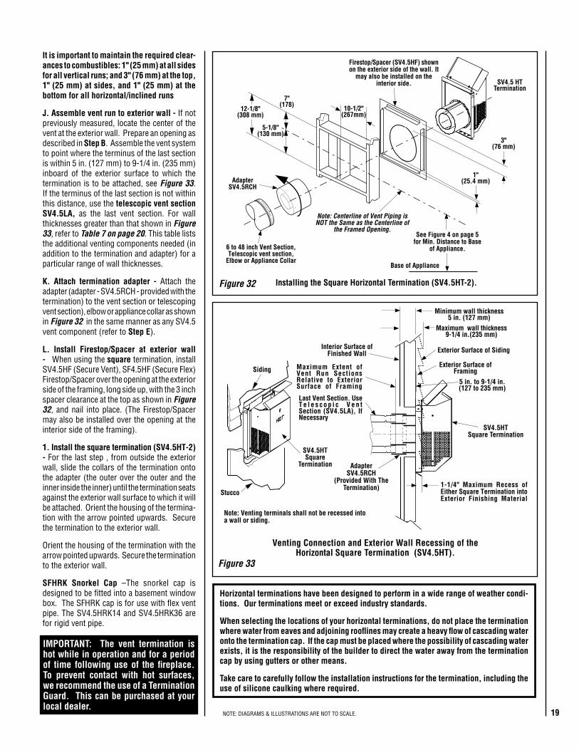
IMPORTANT: The vent termination is hot while in operation and for a period of time following use of the fireplace. To prevent contact with hot surfaces, we recommend the use of a Termination Guard. This can be purchased at your local dealer.
Horizontal terminations have been designed to perform in a wide range of weather condi-tions. Our terminations meet or exceed industry standards.
When selecting the locations of your horizontal terminations, do not place the termination where water from eaves and adjoining rooflines may create a heavy flow of cascading water onto the termination cap. If the cap must be placed where the possibility of cascading water exists, it is the responsibility of the builder to direct the water away from the termination cap by using gutters or other means.
Take care to carefully follow the installation instructions for the termination, including the use of silicone caulking where required.
Figure 33
Siding
Stucco1-1/4" Maximum Recess ofEither Square Termination intoExterior Finishing Material
Exterior Surface ofFraming
5 in. to 9-1/4 in.(127 to 235 mm)
Exterior Surface of Siding
Minimum wall thickness5 in. (127 mm)
Interior Surface ofFinished Wall
Maximum wall thickness9-1/4 in.(235 mm)
SV4.5HTSquare
Termination
Maximum Extent ofVent Run SectionsRelative to ExteriorSurface of Framing
Last Vent Section. UseT e l e s c o p i c V e n tSection (SV4.5LA), IfNecessary
AdapterSV4.5RCH
(Provided With TheTermination)
SV4.5HTSquare Termination
Venting Connection and Exterior Wall Recessing of theHorizontal Square Termination (SV4.5HT).
Note: Venting terminals shall not be recessed intoa wall or siding.
It is important to maintain the required clear-ances to combustibles: 1" (25 mm) at all sides for all vertical runs; and 3" (76 mm) at the top, 1" (25 mm) at sides, and 1" (25 mm) at the bottom for all horizontal/inclined runs
J. Assemble vent run to exterior wall - If not previously measured, locate the center of the vent at the exterior wall. Prepare an opening as described in Step B. Assemble the vent system to point where the terminus of the last section is within 5 in. (127 mm) to 9-1/4 in. (235 mm) inboard of the exterior surface to which the termination is to be attached, see Figure 33. If the terminus of the last section is not within this distance, use the telescopic vent section SV4.5LA, as the last vent section. For wall thicknesses greater than that shown in Figure 33, refer to Table 7 on page 20. This table lists the additional venting components needed (in addition to the termination and adapter) for a particular range of wall thicknesses.
K. Attach termination adapter - Attach the adapter (adapter - SV4.5RCH - provided with the termination) to the vent section or telescoping vent section), elbow or appliance collar as shown in Figure 32 in the same manner as any SV4.5 vent component (refer to Step E).
L. Install Firestop/Spacer at exterior wall - When using the square termination, install SV4.5HF (Secure Vent), SF4.5HF (Secure Flex) Firestop/Spacer over the opening at the exterior side of the framing, long side up, with the 3 inch spacer clearance at the top as shown in Figure 32, and nail into place. (The Firestop/Spacer may also be installed over the opening at the interior side of the framing).
1. Install the square termination (SV4.5HT-2) - For the last step , from outside the exterior wall, slide the collars of the termination onto the adapter (the outer over the outer and the inner inside the inner) until the termination seats against the exterior wall surface to which it will be attached. Orient the housing of the termina-tion with the arrow pointed upwards. Secure the termination to the exterior wall.
Orient the housing of the termination with the arrow pointed upwards. Secure the termination to the exterior wall.
SFHRK Snorkel Cap –The snorkel cap is designed to be fitted into a basement window box. The SFHRK cap is for use with flex vent pipe. The SV4.5HRK14 and SV4.5HRK36 are for rigid vent pipe.
Installing the Square Horizontal Termination (SV4.5HT-2).Figure 32
20 NOTE: DIAGRAMS & ILLUSTRATIONS ARE NOT TO SCALE.
H
V
**Wall Firestop/Spacer(SV4.5HF)
**When using SecureFlex, use Firestop/Spacer
SF4.5VF
*CeilingFirestop/Spacer
(SV4.5VF)
*When using Secure Flex,use Firestop/Spacer
SF4.5HF
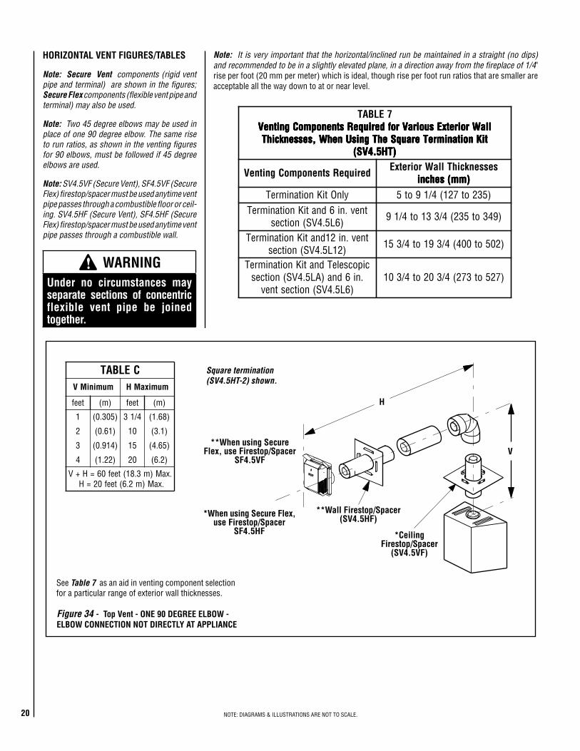
7ELBATllaWroiretxEsuoiraVrofderiuqeRstnenopmoCgnitneV llaWroiretxEsuoiraVrofderiuqeRstnenopmoCgnitneV llaWroiretxEsuoiraVrofderiuqeRstnenopmoCgnitneV llaWroiretxEsuoiraVrofderiuqeRstnenopmoCgnitneV llaWroiretxEsuoiraVrofderiuqeRstnenopmoCgnitneV
tiKnoitanimreTerauqSehTgnisUnehW,sessenkcihT tiKnoitanimreTerauqSehTgnisUnehW,sessenkcihT tiKnoitanimreTerauqSehTgnisUnehW,sessenkcihT tiKnoitanimreTerauqSehTgnisUnehW,sessenkcihT tiKnoitanimreTerauqSehTgnisUnehW,sessenkcihT)TH5.4VS( )TH5.4VS( )TH5.4VS( )TH5.4VS( )TH5.4VS(
deriuqeRstnenopmoCgnitneV sessenkcihTllaWroiretxE)mm(sehcni )mm(sehcni )mm(sehcni )mm(sehcni )mm(sehcni
ylnOtiKnoitanimreT )532ot721(4/19ot5tnev.ni6dnatiKnoitanimreT
)6L5.4VS(noitces )943ot532(4/331ot4/19
tnev.ni21dnatiKnoitanimreT)21L5.4VS(noitces )205ot004(4/391ot4/351
cipocseleTdnatiKnoitanimreT.ni6dna)AL5.4VS(noitces
)6L5.4VS(noitcestnev)725ot372(4/302ot4/301
Figure 34 - Top Vent - ONE 90 DEGREE ELBOW - ELBOW CONNECTION NOT DIRECTLY AT APPLIANCE
See Table 7 as an aid in venting component selection for a particular range of exterior wall thicknesses.
HORIZONTAL VENT FIGURES/TABLES
Note: Secure Vent components (rigid vent pipe and terminal) are shown in the figures; Secure Flex components (flexible vent pipe and terminal) may also be used.
Note: Two 45 degree elbows may be used in place of one 90 degree elbow. The same rise to run ratios, as shown in the venting figures for 90 elbows, must be followed if 45 degree elbows are used.
Note: It is very important that the horizontal/inclined run be maintained in a straight (no dips) and recommended to be in a slightly elevated plane, in a direction away from the fireplace of 1/4" rise per foot (20 mm per meter) which is ideal, though rise per foot run ratios that are smaller are acceptable all the way down to at or near level.
Square termination (SV4.5HT-2) shown.
Note: SV4.5VF (Secure Vent), SF4.5VF (Secure Flex) firestop/spacer must be used anytime vent pipe passes through a combustible floor or ceil-ing. SV4.5HF (Secure Vent), SF4.5HF (Secure Flex) firestop/spacer must be used anytime vent pipe passes through a combustible wall.
ELBAT CmuminiMV mumixaMH
teef )m( teef )m(
1 )503.0( 4/13 )86.1(
2 )16.0( 01 )1.3(
3 )419.0( 51 )56.4(
4 )22.1( 02 )2.6(
.xaM)m3.81(teef06=H+V.xaM)m2.6(teef02=H
WARNING Under no circumstances may separate sections of concentric flexible vent pipe be joined together.
21NOTE: DIAGRAMS & ILLUSTRATIONS ARE NOT TO SCALE.
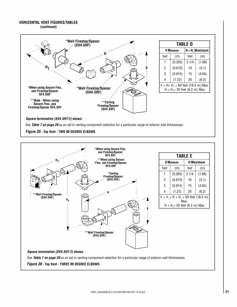
V
H
H1
*Wall Firestop/Spacer(SV4.5HF)
*Wall Firestop/Spacer(SV4.5HF)
*When using Secure Flex,use Firestop/Spacer
SF4.5HF
**CeilingFirestop/Spacer
(SV4.5VF)
**Note - When usingSecure Flex, use
Firestop/Spacer SF4.5VF
DELBATV M MUMINI H + H1 mumixaM
teef )m( teef )m(
1 )503.0( 4/13 )86.1(
2 )016.0( 01 )1.3(
3 )419.0( 51 )56.4(
4 )22.1( 02 )2.6(
H+H+V 1 .xaM)m3.81(teef06=H+H 1 .xaM)m2.6(teef02=
EELBATV M MUMINI H mumixaM
teef )m( teef )m(
1 )503.0( 4/13 )86.1(
2 )016.0( 01 )1.3(
3 )419.0( 51 )56.4(
4 )22.1( 02 )2.6(
V+V 1 H+H+ 1 )m3.81(teef06=.xaM
H+H 1 .xaM)m2.6(teef02=V
H
H1
V1
**Wall Firestop/Spacer(SV4.5HF)
*CeilingFirestop/Spacer
(SV4.5VF)
*When using Secure Flex,use Firestop/Spacer
SF4.5VF**When using Secure
Flex, use Firestop/SpacerSF4.5HF
**Wall Firestop/Spacer(SV4.5HF)
Figure 35 - Top Vent - TWO 90 DEGREE ELBOWS
Figure 36 - Top Vent - THREE 90 DEGREE ELBOWS
See Table 7 on page 20 as an aid in venting component selection for a particular range of exterior wall thicknesses.
HORIZONTAL VENT FIGURES/TABLES (continued)
Square termination (SV4.5HT-2) shown.
See Table 7 on page 20 as an aid in venting component selection for a particular range of exterior wall thicknesses.
Square termination (SV4.5HT-2) shown.
22 NOTE: DIAGRAMS & ILLUSTRATIONS ARE NOT TO SCALE.
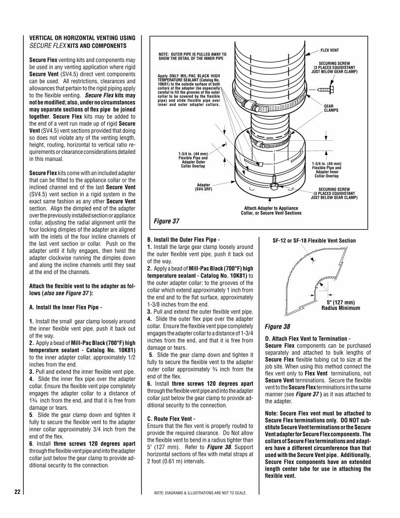
5" (127 mm)Radius Minimum
SF-12 or SF-18 Flexible Vent Section
Figure 38
VERTICAL OR HORIZONTAL VENTING USING SECurE FlEx KITS AND COMPONENTS
Secure Flex venting kits and components may be used in any venting application where rigid Secure Vent (SV4.5) direct vent components can be used. All restrictions, clearances and allowances that pertain to the rigid piping apply to the flexible venting. Secure Flex kits may not be modified; also, under no circumstances may separate sections of flex pipe be joined together. Secure Flex kits may be added to the end of a vent run made up of rigid Secure Vent (SV4.5) vent sections provided that doing so does not violate any of the venting length, height, routing, horizontal to vertical ratio re-quirements or clearance considerations detailed in this manual.
Secure Flex kits come with an included adapter that can be fitted to the appliance collar or the inclined channel end of the last Secure Vent (SV4.5) vent section in a rigid system in the exact same fashion as any other Secure Vent section. Align the dimpled end of the adapter over the previously installed section or appliance collar, adjusting the radial alignment until the four locking dimples of the adapter are aligned with the inlets of the four incline channels of the last vent section or collar. Push on the adapter until it fully engages, then twist the adapter clockwise running the dimples down and along the incline channels until they seat at the end of the channels.
Attach the flexible vent to the adapter as fol-lows (also see Figure 37 ):
A. Install the Inner Flex Pipe -
1. Install the small gear clamp loosely around the inner flexible vent pipe, push it back out of the way.2. Apply a bead of Mill-Pac Black (700°F) high temperature sealant - Catalog No. 10K81) to the inner adapter collar, approximately 1/2
inches from the end.3. Pull and extend the inner flexible vent pipe. 4. Slide the inner flex pipe over the adapter collar. Ensure the flexible vent pipe completely engages the adapter collar to a distance of 1³⁄₄ inch from the end, and that it is free from damage or tears. 5. Slide the gear clamp down and tighten it fully to secure the flexible vent to the adapter inner collar approximately 3/4 inch from the end of the flex.6. Install three screws 120 degrees apart through the flexible vent pipe and into the adapter collar just below the gear clamp to provide ad-ditional security to the connection.
B. Install the Outer Flex Pipe - 1. Install the large gear clamp loosely around the outer flexible vent pipe, push it back out of the way. 2. Apply a bead of Mill-Pac Black (700°F) high temperature sealant - Catalog No. 10K81) to the outer adapter collar; to the grooves of the collar which extend approximately 1 inch from the end and to the flat surface, approximately 1-3/8 inches from the end. 3. Pull and extend the outer flexible vent pipe. 4. Slide the outer flex pipe over the adapter collar. Ensure the flexible vent pipe completely engages the adapter collar to a distance of 1-3/4
inches from the end, and that it is free from damage or tears. 5. Slide the gear clamp down and tighten it fully to secure the flexible vent to the adapter outer collar approximately ³⁄₄ inch from the end of the flex.6. Install three screws 120 degrees apart through the flexible vent pipe and into the adapter collar just below the gear clamp to provide ad-ditional security to the connection.
C. Route Flex Vent - Ensure that the flex vent is properly routed to provide the required clearance. Do Not allow the flexible vent to bend in a radius tighter than 5" (127 mm). Refer to Figure 38. Support horizontal sections of flex with metal straps at 2 foot (0.61 m) intervals.
Note: Secure Flex vent must be attached to Secure Flex terminations only. DO NOT sub-stitute Secure Vent terminations or the Secure Vent adapter for Secure Flex components. The collars of Secure Flex terminations and adapt-ers have a different circumference than that used with the Secure Vent pipe. Additionally, Secure Flex components have an extended length center tube for use in attaching the flexible vent.
D. Attach Flex Vent to Termination - Secure Flex components can be purchased separately and attached to bulk lengths of Secure Flex flexible tubing cut to size at the job site. When using this method connect the flex vent only to Flex Vent terminations, not Secure Vent terminations. Secure the flexible vent to the Secure Flex terminations in the same manner (see Figure 37 ) as it was attached to the adapter.
Figure 37
GEARCLAMPS
Adapter(SV4.5RF)
Apply ONLY MIL-PAC BLACK HIGHTEMPERATURE SEALANT (Catalog No.10K81) to the outside surface of bothcollars of the adapter (be especiallycareful to fill the grooves of the outercollar to be covered by the flexiblepipe) and slide flexible pipe overinner and outer adapter collars.
NOTE: OUTER PIPE IS PULLED AWAY TOSHOW THE DETAIL OF THE INNER PIPE
FLEX VENT
1-3/4 in. (44 mm)Flexible Pipe and
Adapter OuterCollar Overlap 1-3/4 in. (44 mm)
Flexible Pipe and Adapter InnerCollar Overlap
SECURING SCREW(3 PLACES EQUIDISTANT
JUST BELOW GEAR CLAMP)
Attach Adapter to ApplianceCollar, or Secure Vent Sections
SECURING SCREW(3 PLACES EQUIDISTANT
JUST BELOW GEAR CLAMP)
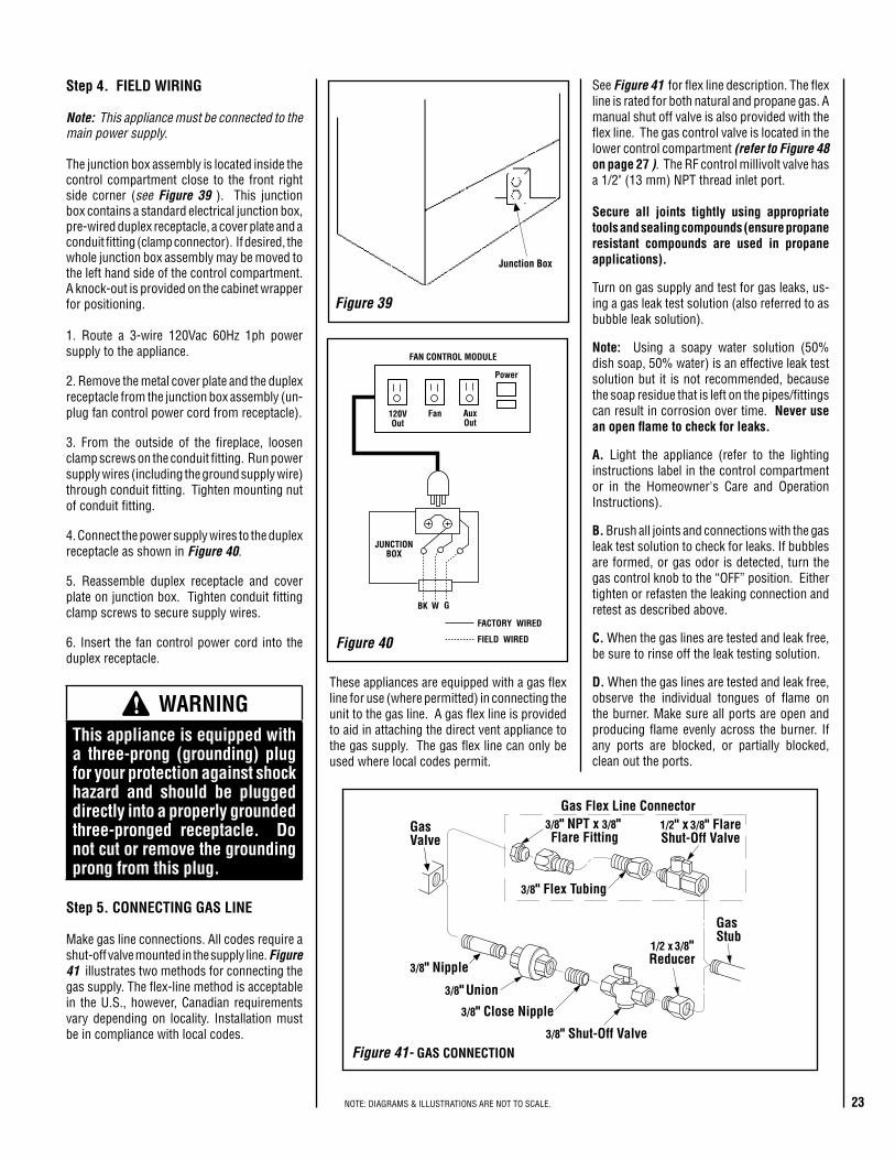
23NOTE: DIAGRAMS & ILLUSTRATIONS ARE NOT TO SCALE.
Step 4. FIELD WIRING
Note: This appliance must be connected to the main power supply.
The junction box assembly is located inside the control compartment close to the front right side corner (see Figure 39 ). This junction box contains a standard electrical junction box, pre-wired duplex receptacle, a cover plate and a conduit fitting (clamp connector). If desired, the whole junction box assembly may be moved to the left hand side of the control compartment. A knock-out is provided on the cabinet wrapper for positioning.
1. Route a 3-wire 120Vac 60Hz 1ph power supply to the appliance.
2. Remove the metal cover plate and the duplex receptacle from the junction box assembly (un-plug fan control power cord from receptacle).
3. From the outside of the fireplace, loosen clamp screws on the conduit fitting. Run power supply wires (including the ground supply wire) through conduit fitting. Tighten mounting nut of conduit fitting.
4. Connect the power supply wires to the duplex receptacle as shown in Figure 40.
5. Reassemble duplex receptacle and cover plate on junction box. Tighten conduit fitting clamp screws to secure supply wires.
6. Insert the fan control power cord into the duplex receptacle.
JUNCTIONBOX
FACTORY WIRED
FIELD WIRED
BK GW
Power
120VOut
Fan AuxOut
FAN CONTROL MODULE
See Figure 41 for flex line description. The flex line is rated for both natural and propane gas. A manual shut off valve is also provided with the flex line. The gas control valve is located in the lower control compartment (refer to Figure 48 on page 27 ). The RF control millivolt valve has a 1/2" (13 mm) NPT thread inlet port.
Secure all joints tightly using appropriate tools and sealing compounds (ensure propane resistant compounds are used in propane applications).
Turn on gas supply and test for gas leaks, us-ing a gas leak test solution (also referred to as bubble leak solution).
Note: Using a soapy water solution (50% dish soap, 50% water) is an effective leak test solution but it is not recommended, because the soap residue that is left on the pipes/fittings can result in corrosion over time. Never use an open flame to check for leaks.
A. Light the appliance (refer to the lighting instructions label in the control compartment or in the Homeowner's Care and Operation Instructions).
B. Brush all joints and connections with the gas leak test solution to check for leaks. If bubbles are formed, or gas odor is detected, turn the gas control knob to the “OFF” position. Either tighten or refasten the leaking connection and retest as described above.
C. When the gas lines are tested and leak free, be sure to rinse off the leak testing solution.
D. When the gas lines are tested and leak free, observe the individual tongues of flame on the burner. Make sure all ports are open and producing flame evenly across the burner. If any ports are blocked, or partially blocked, clean out the ports.
Junction Box
Figure 39
Step 5. CONNECTING GAS LINE
Make gas line connections. All codes require a shut-off valve mounted in the supply line. Figure 41 illustrates two methods for connecting the gas supply. The flex-line method is acceptable in the U.S., however, Canadian requirements vary depending on locality. Installation must be in compliance with local codes.
GasStub
1/2" x 3/8" FlareShut-Off Valve
3/8" Flex Tubing
3/8" NPT x 3/8"Flare Fitting
3/8" Nipple
3/8" Union
3/8" Close Nipple
3/8" Shut-Off Valve
1/2 x 3/8"Reducer
GasValve
Gas Flex Line Connector
WARNING This appliance is equipped with a three-prong (grounding) plug for your protection against shock hazard and should be plugged directly into a properly grounded three-pronged receptacle. Do not cut or remove the grounding prong from this plug.
These appliances are equipped with a gas flex line for use (where permitted) in connecting the unit to the gas line. A gas flex line is provided to aid in attaching the direct vent appliance to the gas supply. The gas flex line can only be used where local codes permit.
Figure 40
Figure 41- GAS CONNECTION
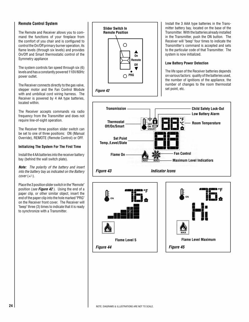
24 NOTE: DIAGRAMS & ILLUSTRATIONS ARE NOT TO SCALE.
Remote Control System
The Remote and Receiver allows you to com-mand the functions of your fireplace from the comfort of you chair and is configured to control the On/Off primary burner operation, its flame levels (through six levels) and provides On/Off and Smart thermostatic control of the Symmetry appliance
The system controls fan speed through six (6) levels and has a constantly powered 110V/60Hz power outlet.
The Receiver connects directly to the gas valve, stepper motor and the Fan Control Module with and umbilical cord wiring harness. The Receiver is powered by 4 AA type batteries, located within.
The Receiver accepts commands via radio frequency from the Transmitter and does not require line-of-sight operation.
The Receiver three position slider switch can be set to one of three positions: ON (Manual Override), REMOTE (Remote Control) or OFF.
Initializing The System For The First Time
Install the 4 AA batteries into the receiver battery bay (behind the wall switch plate).
Note: The polarity of the battery and insert into the battery bay as indicated on the Battery cover (+/-).
Place the 3 position slider switch in the "Remote" position (see Figure 42 ). Using the end of a paper clip, or other similar object, insert the end of the paper clip into the hole marked "PRG" on the Receiver front cover. The Receiver will "beep" three (3) times to indicate that it is ready to synchronize with a Transmitter.
Figure 44
Figure 43 Indicator Icons
Flame Level 5
Transmission
ThermostatOff/On/Smart
Set PointTemp./Level/State
Flame On Fan Control
Child Safety Lock-OutLow Battery Alarm
Room Temperature
Maximum Level Indicatiors
Figure 42
Remote
Off
On
PRG
Slider Switch In Remote Position
Figure 45
Flame Level Maximum
Install the 3 AAA type batteries in the Trans-mitter battery bay, located on the base of the Transmitter. With the batteries already installed in the Transmitter, push the ON button. The Receiver will "beep" four times to indicate the Transmitter's command is accepted and sets to the particular code of that Transmitter. The system is now initialized.
Low Battery Power Detection
The life span of the Receiver batteries depends on various factors: quality of the batteries used, the number of ignitions of the appliance, the number of changes to the room thermostat set point, etc.
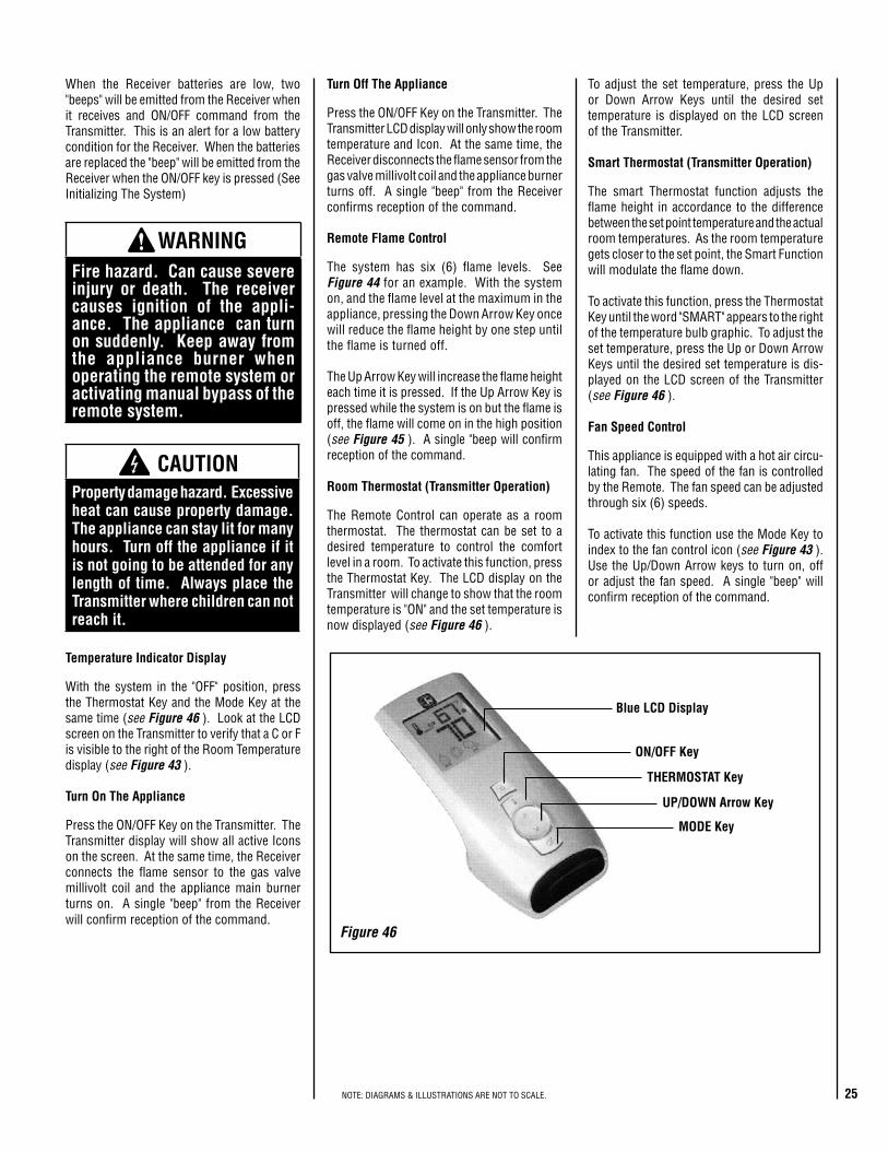
25NOTE: DIAGRAMS & ILLUSTRATIONS ARE NOT TO SCALE.
CAUTIONProperty damage hazard. Excessive heat can cause property damage. The appliance can stay lit for many hours. Turn off the appliance if it is not going to be attended for any length of time. Always place the Transmitter where children can not reach it.
WARNING Fire hazard. Can cause severe injury or death. The receiver causes ignition of the appli-ance. The appliance can turn on suddenly. Keep away from the appliance burner when operating the remote system or activating manual bypass of the remote system.
Turn Off The Appliance
Press the ON/OFF Key on the Transmitter. The Transmitter LCD display will only show the room temperature and Icon. At the same time, the Receiver disconnects the flame sensor from the gas valve millivolt coil and the appliance burner turns off. A single "beep" from the Receiver confirms reception of the command.
Remote Flame Control
The system has six (6) flame levels. See Figure 44 for an example. With the system on, and the flame level at the maximum in the appliance, pressing the Down Arrow Key once will reduce the flame height by one step until the flame is turned off.
The Up Arrow Key will increase the flame height each time it is pressed. If the Up Arrow Key is pressed while the system is on but the flame is off, the flame will come on in the high position (see Figure 45 ). A single "beep will confirm reception of the command.
Room Thermostat (Transmitter Operation)
The Remote Control can operate as a room thermostat. The thermostat can be set to a desired temperature to control the comfort level in a room. To activate this function, press the Thermostat Key. The LCD display on the Transmitter will change to show that the room temperature is "ON" and the set temperature is now displayed (see Figure 46 ).
When the Receiver batteries are low, two "beeps" will be emitted from the Receiver when it receives and ON/OFF command from the Transmitter. This is an alert for a low battery condition for the Receiver. When the batteries are replaced the "beep" will be emitted from the Receiver when the ON/OFF key is pressed (See Initializing The System)
Figure 46
ON/OFF Key
THERMOSTAT Key
UP/DOWN Arrow Key
MODE Key
Blue LCD Display
To adjust the set temperature, press the Up or Down Arrow Keys until the desired set temperature is displayed on the LCD screen of the Transmitter.
Smart Thermostat (Transmitter Operation)
The smart Thermostat function adjusts the flame height in accordance to the difference between the set point temperature and the actual room temperatures. As the room temperature gets closer to the set point, the Smart Function will modulate the flame down.
To activate this function, press the Thermostat Key until the word "SMART" appears to the right of the temperature bulb graphic. To adjust the set temperature, press the Up or Down Arrow Keys until the desired set temperature is dis-played on the LCD screen of the Transmitter (see Figure 46 ).
Fan Speed Control
This appliance is equipped with a hot air circu-lating fan. The speed of the fan is controlled by the Remote. The fan speed can be adjusted through six (6) speeds.
To activate this function use the Mode Key to index to the fan control icon (see Figure 43 ). Use the Up/Down Arrow keys to turn on, off or adjust the fan speed. A single "beep" will confirm reception of the command.
Temperature Indicator Display
With the system in the "OFF" position, press the Thermostat Key and the Mode Key at the same time (see Figure 46 ). Look at the LCD screen on the Transmitter to verify that a C or F is visible to the right of the Room Temperature display (see Figure 43 ).
Turn On The Appliance
Press the ON/OFF Key on the Transmitter. The Transmitter display will show all active Icons on the screen. At the same time, the Receiver connects the flame sensor to the gas valve millivolt coil and the appliance main burner turns on. A single "beep" from the Receiver will confirm reception of the command.
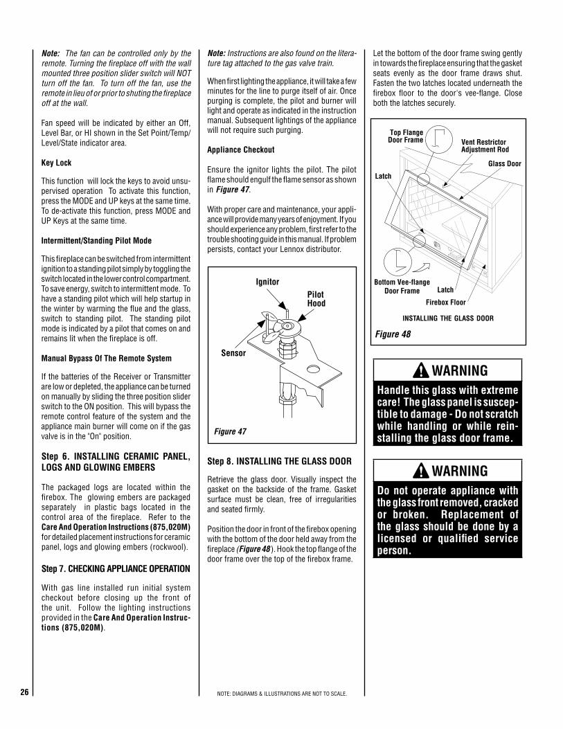
26 NOTE: DIAGRAMS & ILLUSTRATIONS ARE NOT TO SCALE.
Step 6. INSTALLING CERAMIC PANEL, LOGS AND GLOWING EMBERS
The packaged logs are located within the firebox. The glowing embers are packaged separately in plastic bags located in the control area of the fireplace. Refer to the Care And Operation Instructions (875,020M) for detailed placement instructions for ceramic panel, logs and glowing embers (rockwool).
Note: Instructions are also found on the litera-ture tag attached to the gas valve train.
When first lighting the appliance, it will take a few minutes for the line to purge itself of air. Once purging is complete, the pilot and burner will light and operate as indicated in the instruction manual. Subsequent lightings of the appliance will not require such purging.
Appliance Checkout
Ensure the ignitor lights the pilot. The pilot flame should engulf the flame sensor as shown in Figure 47.
With proper care and maintenance, your appli-ance will provide many years of enjoyment. If you should experience any problem, first refer to the trouble shooting guide in this manual. If problem persists, contact your Lennox distributor.
Figure 47
PilotHood
Sensor
Ignitor
Note: The fan can be controlled only by the remote. Turning the fireplace off with the wall mounted three position slider switch will NOT turn off the fan. To turn off the fan, use the remote in lieu of or prior to shuting the fireplace off at the wall.
Fan speed will be indicated by either an Off, Level Bar, or HI shown in the Set Point/Temp/Level/State indicator area.
Key Lock
This function will lock the keys to avoid unsu-pervised operation To activate this function, press the MODE and UP keys at the same time. To de-activate this function, press MODE and UP Keys at the same time.
Intermittent/Standing Pilot Mode
This fireplace can be switched from intermittent ignition to a standing pilot simply by toggling the switch located in the lower control compartment. To save energy, switch to intermittent mode. To have a standing pilot which will help startup in the winter by warming the flue and the glass, switch to standing pilot. The standing pilot mode is indicated by a pilot that comes on and remains lit when the fireplace is off.
Manual Bypass Of The Remote System
If the batteries of the Receiver or Transmitter are low or depleted, the appliance can be turned on manually by sliding the three position slider switch to the ON position. This will bypass the remote control feature of the system and the appliance main burner will come on if the gas valve is in the "On" position.
Step 7. CHECKING APPLIANCE OPERATION
With gas line installed run initial system checkout before closing up the front of the unit. Follow the lighting instructions provided in the Care And Operation Instruc-tions (875,020M).
Step 8. INSTALLING THE GLASS DOOR
Retrieve the glass door. Visually inspect the gasket on the backside of the frame. Gasket surface must be clean, free of irregularities and seated firmly.
Position the door in front of the firebox opening with the bottom of the door held away from the fireplace (Figure 48 ). Hook the top flange of the door frame over the top of the firebox frame.
WARNING Do not operate appliance with the glass front removed, cracked or broken. Replacement of the glass should be done by a licensed or qualified service person.
WARNING Handle this glass with extreme care! The glass panel is suscep-tible to damage - Do not scratch while handling or while rein-stalling the glass door frame.
Let the bottom of the door frame swing gently in towards the fireplace ensuring that the gasket seats evenly as the door frame draws shut. Fasten the two latches located underneath the firebox floor to the door's vee-flange. Close both the latches securely.
Figure 48
installing the glass door
Latch
Latch
Glass Door
Firebox Floor
Bottom Vee-flangeDoor Frame
Top FlangeDoor Frame Vent Restrictor
Adjustment Rod

27NOTE: DIAGRAMS & ILLUSTRATIONS ARE NOT TO SCALE.
To adjust the flame, rotate the air shutter adjustment rod toward the back or toward the front of the fireplace (rod located in the lower control area). Position the air shutter to the factory setting as shown in the Table of Figure 49. Allow the burner to operate for at least 15 minutes. Observe the flame continu-ously. If it appears weak or sooty as previously described, adjust the air shutter by pushing or pulling on the adjustment rod until the flame appearance is as desired.
The air shutter adjustment rod and associated adjustable air shutter is patented technology. Flame adjustments can be made quickly and accurately to taste without the need of disas-sembling the appliance and waiting for 30 minutes after each adjustment.
When satisfied that the appliance operates properly, proceed to finish the installation. Leave the control knob in the ON position and the remote switch OFF.
Vent Restrictor
The appliance has a built-in vent restrictor, refer to Figure 49 for location of the adjustment rod, to adjust the flow of exhaust gases. This ensures proper combustion for all vent configu-rations. Depending on the vent configuration, you may be required to adjust the restriction position. See below for guidelines.
Burner Adjustment sledoM saGepyT
RIAYROTCAFGNITTESRETTUHS
GNINEPO)mm(sehcni
53-SSL.taN 2/1 )0.31(.porP 8/5 )8.51(
04-SSL.taN 2/1 )0.31(.porP 8/5 )8.51(
Step 9. BURNER ADJUSTMENTS
Flame Appearance and sooting
Proper flame appearance is a matter of taste. Generally, most people prefer the warm glow of a yellow to orange flame. Appliances operated with air shutter openings that are too large will exhibit flames that are blue and transparent. These weak, blue and transparent flames are termed anemic. If the air shutter opening is too small sooting may develop.
Sooting is indicated by black puffs developing at the tips of very long orange flames. Sooting results in black deposits forming on the logs, appliance inside surfaces and on exterior surfaces adjacent to the vent termination.
Sooting is caused by incomplete combustion in the flames and lack of combustion air entering the air shutter opening. To achieve a warm yellow to orange flame with an orange body that does not soot, the shutter opening must be adjusted between these two extremes.
No smoke or soot should be present. Reposition the logs if flames impinge on any of them. If the logs are properly positioned and sooting condi-tions exist, the air shutter opening on the main burner tube should be adjusted. Normally, the more offsets in the vent system, the greater the need for the air shutter to be opened further.
* Adjustment to the air shutter may be required to get the desired flame appearance, (refer to Figure 49 ).
1. Horizontal Venting with 6" vent section and one 90° elbow.
* Pointed toward the front.
2. Vertical venting.
3. Combination of ver-tical and horizontal venting.
* Pointed toward the left.
* Adjust accordingly for best result.
Venting Configuration
Adjustment Rod Position
IMPORTANT: ENSURE THAT THE FRONT GLASS PANEL IS IN PLACE AND SEALED DURING ADJUSTMENT.
Figure 49
Air ShutterOpening
BurnerVenturiTube
Air ShutterArm
Orifice
Air ShutterAdjusting
Rod
WARNING Air shutter adjustment should only be performed by a qualified professional service technician.
CAUTION The air shutter adjustment rod and nearby appliance surfaces are hot. Exercise caution to avoid injury while adjusting flame appearance.
FINISHING REQUIREMENTSWall Details
Complete finished interior wall. To install the appliance facing flush with the finished wall, position framework to accommodate the thick-ness of the finished wall (Figure 50 ).
CAUTION The fireplace needs to be on during the adjustment of the vent restrictor. Use a glove to protect your hand from burns.
Figure 50
This Area MustRemain Clear ofCombustibleMaterials
3" Min (76 mm)
Stand-Off
1/2”Cement
Board
Marble,Tile, Or
Other Non-Combustible
Materials Fireplace
2”x 4”Header
1/2”Drywall
1" Min(25.4 mm)
1/2” Drywall

28
STEP 10. ATTACHING SAFETY-IN-OPERATION WARNINGS
It is the installers responsibility to ensure these warnings are properly affixed during installation. These warning labels are a critical step in informing consumers of safe operation of this appliance.
ATTACHING SAFETY-IN-OPERATION WARNINGS
Your fireplace has been furnished with safety instruc-tion labels that are to be affixed to the operation and control points of the fireplace. A safety instruction label should be affixed to the receiver wall switch plate where the fireplace is turned on and off (See Figure A) and the remote control handheld transmitter (Figure B). The warnings should already have been put in place when the fireplace initial set-up was completed. If they are not affixed at these spots, locate the multi-lingual adhesive labels provided with these instructions and proceed as follows:1. Locate the wall receiver that controls the fireplace
(verify the switch operates the fireplace by turn-ing it on and off). Clean the wall receiver plate thoroughly to remove any dust and oils. Affix the label to the surface of the plate of the wall receiver that controls the fireplace (Figure A). Choose the language primarily spoken in the home.
2. Locate the remote control transmitter and clean it thoroughly to remove any dust and oils. Affix the label to the surface of handheld transmitter (Figure B). Choose the language primarily spoken in the home.
3. If you are unable to locate the labels, please call Lennox Hearth Products or your nearest Lennox Hearth Products dealer to receive additional safety instruction labels free of charge.
Cat. No. H8024 Replacement Label Kit
LENNOX HEARTH PRODUCTS1-800-9-LENNOX
Note: English is red text on clear label. French and Spanish are white text on black label.
Remote
Off
On
PRG
Figure A Figure B
APPOSITION DES MISES EN GARDE RELATIVES à LA SéCURITé D’UTILISATION
Votre foyer a été livré avec des étiquettes de sécurité qui doivent être collées à côté des dispositifs de contrôle du foyer. Une étiquette de sécurité devrait être collée sur la plaque du récepteur mural contrôlant l’allumage du foyer (voir Figure A) et sur le boîtier de la télécommande (Figure B). Les mises en garde auraient dû être collées au moment de l’installation initiale du foyer. Si ce n’est pas le cas, prenez les étiquettes adhésives multilingues fournies avec ces instructions et procédez comme suit:1. Repérez le récepteur mural qui contrôle le foyer
(vérifiez que l’interrupteur contrôle le fonction-nement du foyer en le faisant basculer de Marche à Arrêt, et vice-versa). Nettoyez soigneusement la plaque du récepteur mural pour éliminer la poussière et les traces de graisse ou d’huile. Collez l’étiquette sur la surface de la plaque du récepteur mural qui contrôle le foyer (Figure A). Choisissez la langue qui est principalement parlée dans la résidence du propriétaire.
2. Repérez la télécommande et nettoyez-la soigneuse-ment pour éliminer la poussière et les traces de graisse ou d’huile. Collez l’étiquette sur le boîtier de la télécommande (Figure B). Choisissez la langue qui est principalement parlée dans la résidence du propriétaire.
3. Si vous ne trouvez pas les étiquettes, veuillez appeler Lennox Hearth Products ou votre distribu-teur Lennox Hearth Products local pour recevoir gratuitement des étiquettes supplémentaires.
Étiquettes de remplacement, n° cat. H8024
LENNOX HEARTH PRODUCTS1-800-9-LENNOX
Remarque : Le texte anglais est rouge sur un support transparent. Le texte français et espagnol est blanc sur un support noir.
COLOCACIóN DE ADVERTENCIAS DE SEGURIDAD EN OPERACIóN
Su chimenea incluye etiquetas de instrucciones de seguridad que deben colocarse en los puntos de operación y control de la chimenea. Se debe colocar una etiqueta de instrucciones de seguridad en la placa del interruptor de pared del receptor desde el cual se enciende y se apaga la chimenea (ver la Figura A) y en el transmisor de control remoto (Figura B). Las advertencias ya deben haberse colocado cuando se completó la instalación inicial de la chimenea. Si no están colocadas en estos lugares, encuentre las etiquetas adhesivas multilingües proporcionadas con estas instrucciones y prosiga de la siguiente manera:1. Identifique el receptor de pared que controla la
chimenea (verifique que el interruptor opera la chimenea encendiéndola y apagándola). Limpie bien la placa del receptor de pared para quitar el polvo y aceite. Pegue la etiqueta en la superficie de la placa del receptor de pared que controla la chimenea (Figura A). Seleccione el idioma que más se habla en la casa.
2. Identifique el transmisor de control remoto y límpielo bien para quitar el polvo y aceite. Pegue la etiqueta en la superficie del transmisor (Figura B). Seleccione el idioma que más se habla en la casa.
3. Si no puede encontrar las etiquetas, sírvase llamar a Lennox Hearth Products o al distribuidor de Lennox Hearth Products más cercano para recibir etiquetas de instrucciones de seguridad adicionales gratuitas.
Juego de etiquetas de repuesto - Nº de cat. H8024
LENNOX HEARTH PRODUCTS1-800-9-LENNOX
Nota: La etiqueta en inglés es transparente con texto rojo. Las etiquetas en francés y español son negras con texto blanco.
SAFETY LABEL DIAGRAMS
DIAGRAMAS DE ETIQUETAS DE SEGURIDAD
DIAGRAMMES DES éTIQUETTES DE SéCURITé

29NOTE: DIAGRAMS & ILLUSTRATIONS ARE NOT TO SCALE.
INSTALLATION ACCESSORIES
detsiL tneVeruceS stnenopmoC™.oN.taC .oNledoM noitpircseD30L9920L99
63KRH5.4VS41KRH5.4VS
"63tiKresiRlatnoziroH"41tiKresiRlatnoziroH
8691H 2-TH5.4VS erauqSlatnoziroHhtiwnoitanimreT
)08K69(recapS/potseriF)16L47(retpadAdna
*All compressed flex vents can be expanded up to two times.
detsiL xelFeruceS stnenopmoC™.taC.oN .oN .oN .oN .oN
ledoM.oN .oN .oN .oN .oN noitpircseD
.retpadaxelfdnaspmalcraeg,recaps/potserifedulcnistiknoitanimretesehT9691H 2-TH5.4FS noitanimreTerauqSlatnoziroH
xelFtuohtiw78L77 21TIKFS .ni21htiw.mreTerauqSxelF
xelFdesserpmoc*fomm503(88L77 81TIKFS .ni81htiw.mreTerauqSxelF
xelFdesserpmoc*fo)mm754(98L77 42TIKFS .ni42htiw.mreTerauqSxelF
xelFdesserpmoc*fo)mm016(09L77 63TIKFS .ni63htiw.mreTerauqSxelF
xelFdesserpmoc*fo)mm419(19L77 84TIKFS .ni84htiw.mreTerauqSxelF
xelFdesserpmoc*fo)mm9121(47L65 03TVFS ottalf(xelFrof.nimreTlacitreV
noitces,retpadAxelFhtiw)21/6ralloctroppusfoor,tnevdigirfo
dnagnihsalffoor,ylbmessa.rallocmrots
57L65 54TVFS ot21/6(xelFrof.nimreTlacitreVnoitcesretpadAxelFhtiw)21/21ralloctroppusfoor,tnevdigirfo
dnagnihsalffoor,ylbmessa.rallocmrots
8891H
5891H
7891H
6891H
33-ASTC
33-OSTC
44-OSTC
64-OSTC
,tiKduorhSpoTesahC3X3-poThcrA
,tiKduorhSpoTesahC3X3-poTnepO
,tiKduorhSpoTesahC4X4-poTnepO
,tiKduorhSpoTesahC6X4-poTnepO
01L06 81-FS xelFdesserpmoc*)m94.5(.tf8130K89 21-FS xelFdesserpmoc*)m66.3(.tf2118K01
04L98
PMFS
21-PMFS
erutarepmeT-iHkcalBcaPliMtnalaeS
erutarepmeT-iHkcalBcaPliM21kcaPkluB-tnalaeS
66L19 6-4CG-FS rof)mm411(.ni5.4pmalCraeG)seceip6(xelF
76L19 6-7CG-FS )mm5.091(.ni5.7pmalCraeG)seceip6(xelFrof
8422H FH5.4FS kcaP01-recapS/potseriF)gnicaps1-1-3(latnoziroH
9422H FV5.4FS kcaP01-recapS/potseriF)gnicaps1-1-1(lacitreV
)detartsulliton(8477H 63KVF tiKrotcennoCxelF"63
Seala
nt
detsiL tneVeruceS stnenopmoC™.oN.taC .oNledoM noitpircseD2512H 1-VGC5.4VS noitanimreTlacitreV
07L77 6L5.4VS tneV)mm251(hcni6noitceS
17L77 21L5.4VS tneV)mm503(hcni21noitceS
27L77 42L5.4VS tneV)mm016(hcni42noitceS
37L77 63L5.4VS tneV)mm419(hcni63noitceS
47L77 84L5.4VS tneV)mm9121(hcni84noitceS
57L77 AL5.4VS noitceScipocseleT67L77 54E5.4VS woblEeergeD54
77L77 09E5.4VS woblEeergeD09
.rallocmrotsahtiwdegakcapemocsgnihsalfgniwollofehT87L77 F5.4VS gnihsalFfooRtalF97L77 AF5.4VS gnihsalF.tsujdA21/7ot21/1
08L77 BF5.4VS .tsujdA21/21ot21/7gnihsalF
18L77 6CS5.4VS )xob/sralloc6(sralloCmrotS
6422H FH5.4VS kcaP01-recapS/potseriF)gnicaps1-1-3(latnoziroH
7422H FV5.4VS kcaP01-recapS/potseriF)gnicaps1-1-1(lacitreV
39K69 US5.4VS partStroppuS
49K69 ASR5.4VS dleihSnoitalusnIcittA
29K69 PS5.4VS
25M71 5.4VS1-SGH
erauqSdrauGtaeH)kcaP-1(
35M71 5.4VS21-SGH
erauqSdrauGtaeH)kcaP-21(

30 NOTE: DIAGRAMS & ILLUSTRATIONS ARE NOT TO SCALE.
GAS CONVERSION KITS
In Canada
THE CONVERSION SHALL BE CARRIED OUT IN ACCORDANCE WITH THE REQUIREMENTS OF THE PROVINCIAL AUTHORITIES HAVING JURISDICTION AND IN ACCORDANCE WITH THE REQUIREMENTS OF THE CAN1-B149.1 AND .2 INSTALLATION CODE.
LA CONVERSION DEVRA ÊTRE EFFECTUéE CONFORMéMENT AUX RECOMMANDA-TIONS DES AUTORITéS PROVINCIALES AYANT JURIDICTION ET CONFORMéMENT AUX EXIGENCES DU CODE D'INSTALLATION CAN1-B149.1 ET.2.
This Gas Conversion Kit contains all of the necessary components needed to complete the conversion of an appliance from the use of one type of gas to the use of another, including labeling that must be affixed to ensure safe operation.
ALWAYS REFER TO THE APPLIANCE IN-STALLATION AND CARE AND OPERATION DOCUMENTS BEFORE COMPLETING A CONVERSION. ALL WARNINGS, CAUTIONS AND DETAILED INSTRUCTIONS CONTAINED THEREIN ARE APPLICABLE HERE.
Note: After converting the valve and gas com-ponents, refer to the appliance installation and care and operation instructions to adjust the air shutter opening for the gas type used.
Kit part numbers are listed here and the follow-ing steps detail the conversion procedure.
Step 1. Turn off the gas supply to the ap-pliance. Remove the front frame and glass door from the appliance. Access the control compartment.
Step 2. Carefully remove the logs. Exercise care as not to break the logs.
Step 3. Remove the grate.
See Figure 51 for Step 4 part removal details.
Burner Assembly
Front Baffle
Front BaffleSecuring Screw
Front Burner
Front BurnerSecuring Screw
Burner ClampSecuring Screw Rear Burner
Burner Clamp
WARNING: THIS CONVERSION KIT SHALL BE INSTALLED BY A QUALIFIED SERVICE AGENCY IN ACCORDANCE WITH THE MANUFACTURER'S INSTRUCTIONS AND ALL APPLICABLE CODES AND REQUIREMENTS OF THE AUTHORITY HAVING JURISDICTION. IF THE INFORMATION IN THESE INSTRUCTIONS IS NOT FOLLOWED EXACTLY, A FIRE, EXPLOSION OR PRODUCTION OF CARBON MONOXIDE MAY RESULT CAUSING PROPERTY DAMAGE, PERSONAL INJURY OR LOSS OF LIFE. THE INSTALLATION IS NOT PROPER AND COM-PLETE UNTIL THE OPERATION OF THE CONVERTED APPLIANCE IS CHECKED AS SPECIFIED IN THE OWNER INSTRUCTIONS SUPPLIED WITH THE KIT.THE QUALIFIED SERVICE AGENCY PERFORMING THIS INSTALLATION ASSUMES RESPONSIBILITY FOR THIS CONVERSION.
AVERTISSEMENT: CET éQUIPEMENT DE CONVERSION SERA INSTALLé PAR UNE AGENCE QUALIFIéE DE SERVICE CONFORMéMENT AUX INSTRUCTIONS DU FABRICANT ET TOUTES EXIGENCES ET CODES APPLI-CABLES DE L'AUTORISéS AVOIR LA JURIDICTION. SI L'INFORMATION DANS CETTE INSTRUCTION N'EST PAS SUIVIE EXACTEMENT, UN FEU, EXPLOSION OU PRODUC-TION DE PROTOXYDE DE CARBONE PEUT RéSULTER LE DOMMAGES CAUSER DE PROPRIéTé, PERTE OU BLESSURE PERSONNELLE DE VIE. L'AGENCE QUALI-FIéE DE SERVICE EST ESPONSABLE DE L'INSTALLATION PROPRE DE CET éQUIPMENT. L'INSTALLATION N'EST PAS PROPRE ET COMPLéTE JUSQU'à L'OPéRATION DE L'APPAREIL CONVERTI EST CHéQUE SUIVANT LES CRITèRES éTABLIS DANS LES INSTRUCTIONS DE PRO-PRIéTAIRE PROVISIONNéES AVEC L'éQUIPEMENT.
Natural To Propane Gas Conversion KitsModels Catolog No.LSS-35 H7852LSS-40 H7853
Propane To Natural Gas Conversion KitModels Catolog No.LSS-35 H7854LSS-40 H7855
Figure 51
Step 4
a. Remove the front baffle by removing the two securing screws.
b. Remove the two screws securing the end tabs of the front burner. Remove the front burner.
c. Remove the two screws securing each of the rear burner clamps. Remove the rear burner.

31NOTE: DIAGRAMS & ILLUSTRATIONS ARE NOT TO SCALE.
Figure 53
PilotOrifice
Electronic Appliances
Step 5. SIT Systems - Refer to Figure 52 and the instructions provided with the kit. Discard all removed components.
Step 6. Shut off the gas supply to the valve and shut down the electric supply.
Step 7. See Figure 52. Using a Torx T20, or slotted screwdriver, remove and discard the two (2) pressure regulator mounting screws, pres-sure regulator tower, the diaphragm assembly (A) (if applicable) and the spring (B).
Step 8. Ensure the rubber gasket (C), which is pre-fitted as part of the assembly, is properly positioned (see Figure 52 ).
Step 9. Install the new Stepper Motor pressure regulator assembly using the supplied screws as shown in Figure 44. Tighten screws securely (reference torque = 25 lb. in.).
Step 10. Install the enclosed identification label to the valve body where it can be easily seen.
Step 11. Make Stepper Motor and valve electri-cal connections.
Step 12. Attach manometer to the manifold side pressure test fitting and verify manifold pressure reads 3.5 inches water column (0.87 kPa) for natural gas, and 10.0 inches water column (2.49 kPa) for propane gas (see Figure 52 ).
Step 13. See Figure 53 and replace the pilot orifice as follows: Remove the pilot hood assembly to access the hexed pilot orifice. Remove and replace the orifice with the one provided with the kit. Exercise extreme care to prevent damage to or breakage of the ignitor assembly.
Figure 52
Pressure Regulator
Tower
Pressure Regulator Mounting Screws (Torx-T20)
Connect GTMS Wire Harness
(A) Remove Diaphragm(B) Remove SpringInstall New:Pressure Regulator Tower(C) Rubber Gasket
Line (In) Test Port
Manifold (Out) Test Port
Rear Main Burner Orifice
Front MainBurner Orifice
Gas Valve
Figure 54

32 NOTE: DIAGRAMS & ILLUSTRATIONS ARE NOT TO SCALE.
NOTE: DIAGRAMS & ILLUSTRATIONS ARE NOT TO SCALE.
Printed in U.S.A. © 2002 by Lennox Hearth Products
P/N 850016M REV. L 01/2011
Lennox Hearth Products reserves the right to make changes at any time, without notice, in design, materials, specifications, prices and also to discontinue colors, styles and products. Consult your local distributor for fireplace code information.
1508 Elm Hill Pike, Suite 108 • Nashville, TN 37210
Step 17. Attach a manometer to the manifold side pressure test fitting and verify manifold pressure reads 3.5 inches water column (0.87 kPa) for natural gas, and 10.0 inches water column (2.49 kPa) for propane gas.
Step 18. Apply gas to the system and relight appliance. With the main burner "ON", test the new pressure regulator assembly for leaks using a leak test solution.
Step 19. Relight the main burner and verify proper burner ignition and operation.
Example Labels(Each Kit Contains Only One Label)
THIS APPLIANCE HAS BEEN CONVERTED TO:
NATURAL GASINPUT BTU/HR – 50,000
MANIFOLD PRESSURE – 3.5"
ORIFICE SIZE – (0.130)
THIS APPLIANCE HAS BEEN CONVERTED TO:
PROPANE/LPGINPUT BTU/HR – 50,000
MANIFOLD PRESSURE – 10"
ORIFICE SIZE – (0.080)
size
Figure 55
Figure 56
Step 15. Reassemble all removed components by reversing the procedures outlined in the preceding steps. Use pipe joint compound or Teflon tape on all pipe fittings before installing (ensure propane resistant compounds are used in propane applications, do not use pipe joint compounds on flare fittings). Adjust the air shutter opening on the burner tube, referring to Figure 49 on page 27.
Step 16. Attach the conversion kit label (Figure 56 ) to the rating plate on the appliance.
Step 14. Unscrew the rear and front main burner orifices (refer to Figure 54 ) from their respective manifolds and replace them with the ones provided in this kit. There are two main burner orifices provided in this gas conversion kit. Refer to Table below for the correct front and rear main burner orifice sizes for the gas being used. The orifice size is stamped on the orifice. See Figure 55.
ledoM leuF raeRrenruB
tnorFrenruB
NC53-SSL saG.taN 44# 05#
PC53-SSL saGPL 55# 16#
NC04-SSL saG.taN 24# 54#
PC04-SSL saGPL "450.0 65#
WARNING Incorrect orifice size installation on either burner may result in poor combustion which may lead to the production of carbon monoxide. It may also cause sooting within the fireplace/venting system.