Embed Size (px)
Citation preview
601 Old Airport Road • Bristol, VA 24201 Phone (276) 466-8200 • FAX (276) 645-8212 • www.federalpacific.com • ISO 9001:2008 Registered
SECTION IB-1A-110INSTALLATION & OPERATION INSTRUCTIONS
PAD-MOUNTED SWITCHGEAR TYPE PSI/IIREV. 4.6 — JULY 2017
Page 1
TYPE PSI/II
PAD-MOUNT SWITCHGEAR15kV • 25kV
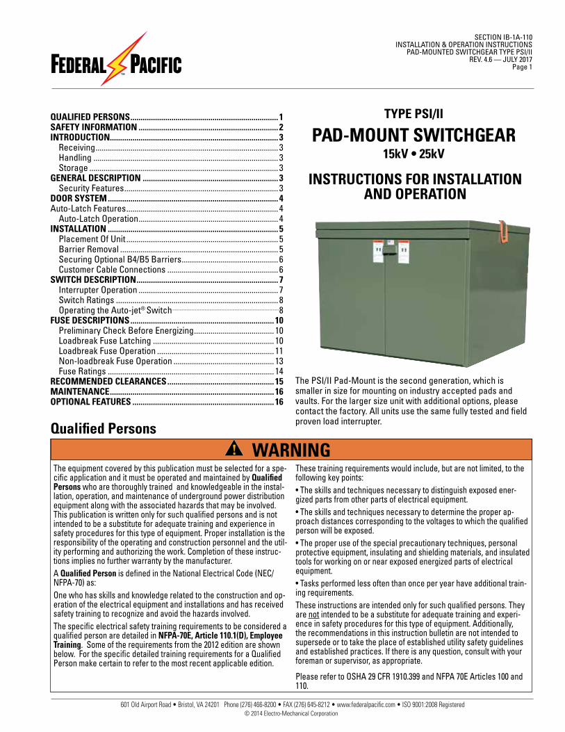
The PSI/II Pad-Mount is the second generation, which is smaller in size for mounting on industry accepted pads and vaults. For the larger size unit with additional options, please contact the factory. All units use the same fully tested and field proven load interrupter.
INSTRUCTIONS FOR INSTALLATION AND OPERATION
QUALIFIED PERSONS ........................................................................ 1SAFETY INFORMATION .................................................................... 2INTRODUCTION.................................................................................. 3 Receiving ......................................................................................... 3 Handling .......................................................................................... 3 Storage ............................................................................................ 3GENERAL DESCRIPTION .................................................................. 3 Security Features ........................................................................... 3DOOR SYSTEM ................................................................................... 4 Auto-Latch Features .......................................................................... 4 Auto-Latch Operation .................................................................... 4 INSTALLATION ................................................................................... 5 Placement Of Unit .......................................................................... 5 Barrier Removal ............................................................................. 5 Securing Optional B4/B5 Barriers ............................................... 6 Customer Cable Connections ...................................................... 6SWITCH DESCRIPTION ..................................................................... 7 Interrupter Operation .................................................................... 7 Switch Ratings ............................................................................... 8 Operating the Auto-jet® Switch .........................................................................................8FUSE DESCRIPTIONS ...................................................................... 10 Preliminary Check Before Energizing ....................................... 10 Loadbreak Fuse Latching ........................................................... 10 Loadbreak Fuse Operation ......................................................... 11 Non-loadbreak Fuse Operation ................................................. 13 Fuse Ratings ................................................................................. 14RECOMMENDED CLEARANCES .................................................... 15MAINTENANCE ................................................................................ 16OPTIONAL FEATURES ..................................................................... 16
© 2014 Electro-Mechanical Corporation
Qualified Persons
The equipment covered by this publication must be selected for a spe-cific application and it must be operated and maintained by Qualified Persons who are thoroughly trained and knowledgeable in the instal-lation, operation, and maintenance of underground power distribution equipment along with the associated hazards that may be involved. This publication is written only for such qualified persons and is not intended to be a substitute for adequate training and experience in safety procedures for this type of equipment. Proper installation is the responsibility of the operating and construction personnel and the util-ity performing and authorizing the work. Completion of these instruc-tions implies no further warranty by the manufacturer.A Qualified Person is defined in the National Electrical Code (NEC/NFPA-70) as:One who has skills and knowledge related to the construction and op-eration of the electrical equipment and installations and has received safety training to recognize and avoid the hazards involved.The specific electrical safety training requirements to be considered a qualified person are detailed in NFPA-70E, Article 110.1(D), Employee Training. Some of the requirements from the 2012 edition are shown below. For the specific detailed training requirements for a Qualified Person make certain to refer to the most recent applicable edition.
These training requirements would include, but are not limited, to the following key points:• The skills and techniques necessary to distinguish exposed ener-gized parts from other parts of electrical equipment.• The skills and techniques necessary to determine the proper ap-proach distances corresponding to the voltages to which the qualified person will be exposed.• The proper use of the special precautionary techniques, personal protective equipment, insulating and shielding materials, and insulated tools for working on or near exposed energized parts of electrical equipment.• Tasks performed less often than once per year have additional train-ing requirements.These instructions are intended only for such qualified persons. They are not intended to be a substitute for adequate training and experi-ence in safety procedures for this type of equipment. Additionally, the recommendations in this instruction bulletin are not intended to supersede or to take the place of established utility safety guidelines and established practices. If there is any question, consult with your foreman or supervisor, as appropriate.
Please refer to OSHA 29 CFR 1910.399 and NFPA 70E Articles 100 and 110.
WARNING

601 Old Airport Road • Bristol, VA 24201 Phone (276) 466-8200 • FAX (276) 645-8212 • www.federalpacific.com • ISO 9001:2008 Registered
SECTION IB-1A-110INSTALLATION & OPERATION INSTRUCTIONSTYPE PM PAD-MOUNTED SWITCHGEAR TYPE PSI/IIREV. 4.6 — JULY 2017Page 2
SAFETY INFORMATION
Understanding Safety-Alert MessagesThere are several types of safety-alert messages which may appear throughout this instruction bulletin as well as on labels attached to the padmounted switchgear. Familiarize yourself with these types of messages and the importance of the various signal words, as explained below.
If you do not understand any portion of this instruction bulletin and need assistance, contact Federal Pacific at 276-466-8200.
Replacement Instructions & LabelsIf you need additional copies of this instruction bulletin, contact Federal Pacific at 276-466-8200.
It is important that any missing, damaged, or faded labels on the equipment be replaced immediately. Replacement labels are available by contacting Federal Pacific.
SAFETY PRECAUTION
FOLLOWING SAFETY INSTRUCTIONS
NOTICENOTICE is used to address practices not related to physical injury.
SAFETY INSTRUCTIONSSafety Instructions (or equivalent) signs indicate specific safety-related instructions or procedures.
DANGER indicates a hazardous situation which, if not avoided, will result in death or serious injury.
DANGER
WARNINGWARNING indicates a hazardous situation which, if not avoided, could result in death or serous injury.
CAUTIONCAUTION indicates a hazardous situation which, if not avoided, could result in minor or moderate injury.
DANGERFederal Pacific Fuse Mountings in conjunction with appropri-ate fuses are designed to protect equipment and to discon-nect faulted equipment from the system. The fuses cannot protect personnel from injury or electrocution if contact is made with energized circuits or hardware.
NOTICE......
Thoroughly and carefully read this instruction bulletin before installation of the pad-mounted switchgear, before switching or operating the switches or fuse mountings in this equipment,
and before performing any maintenance on the equipment.
601 Old Airport Road • Bristol, VA 24201 Phone (276) 466-8200 • FAX (276) 645-8212 • www.federalpacific.com • ISO 9001:2008 Registered
SECTION IB-1A-110INSTALLATION & OPERATION INSTRUCTIONS
PAD-MOUNTED SWITCHGEAR TYPE PSI/IIREV. 4.6 — JULY 2017
Page 3
IntroductionType PSI/II pad-mounted switchgear is designed to make installation, operation and maintenance as simple as possible and to provide dependable on-the-line service.
High quality materials and careful workmanship have been combined to provide the best switchgear available. The switchgear has been thoroughly inspected and adjusted at the factory. However, successful operation depends on proper installation and care.
This manual has been written to assist you in obtaining long and economical service from your switchgear.
Read this manual before installing and operating your switch-gear.
ReceivingUpon receipt of the switchgear, check each item received for shipping damage. Each item should be checked against the shipping manifest to assure that the proper number of items were received. Should any shortage or damage exist, to main-tain the warranty a claim must be filed immediately with the carrier, (by making note of the damage on the shipping papers) and the Federal Pacific agent or sales office must be notified.
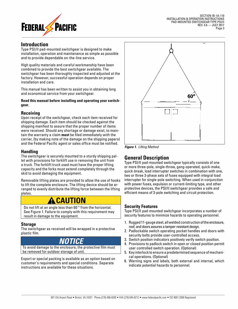
HandlingThe switchgear is securely mounted to a sturdy shipping pal-let with provisions for forklift use in removing the unit from a truck. The forklift truck used must have the proper lifting capacity and the forks must extend completely through the skid to avoid damaging the equipment.
Removable lifting plates are provided to allow the use of hooks to lift the complete enclosure. The lifting device should be ar-ranged to evenly distribute the lifting force between the lifting plates.
Do not lift at an angle less than 60 ° from the horizontal. See Figure 1. Failure to comply with this requirement may result in damage to the equipment.
StorageThe switchgear as received will be wrapped in a protective plastic film.
To avoid damage to the enclosure, the protective film must be removed for outdoor storage of unit.
Export or special packing is available as an option based on customer's requirements and special conditions. Separate instructions are available for these situations.
Figure 1. Lifting Method
General DescriptionType PSI/II pad-mounted switchgear typically consists of one or more three-pole, single-throw, gang-operated, quick-make, quick-break, load interrupter switches in combination with one, two or three 3-phase sets of fuses equipped with integral load interrupter for single-pole switching. When used in conjunction with power fuses, expulsion or current-limiting type, and other protective devices, the PSI/II switchgear provides a safe and efficient means of 3-pole switching and circuit protection.
Security FeaturesType PSI/II pad-mounted switchgear incorporates a number of security features to minimize hazards to operating personnel.
1. Rugged 11-gauge steel, all welded construction of the enclosure, roof, and doors assures a tamper-resistant design.
2. Padlockable switch operating pocket handles and doors with security bolts provide user-controlled access.
3. Switch position indicators positively verify switch position.4. Provisions to padlock switch in open or closed position permit
user controlled switch operation. (Optional)5. Key interlock to ensure a predetermined sequence of mechani-
cal operations. (Optional)6. Warning signs and labels, both external and internal, which
indicate potential hazards to personnel.
CAUTION
NOTICE
601 Old Airport Road • Bristol, VA 24201 Phone (276) 466-8200 • FAX (276) 645-8212 • www.federalpacific.com • ISO 9001:2008 Registered
SECTION IB-1A-110INSTALLATION & OPERATION INSTRUCTIONSTYPE PM PAD-MOUNTED SWITCHGEAR TYPE PSI/IIREV. 4.6 — JULY 2017Page 4
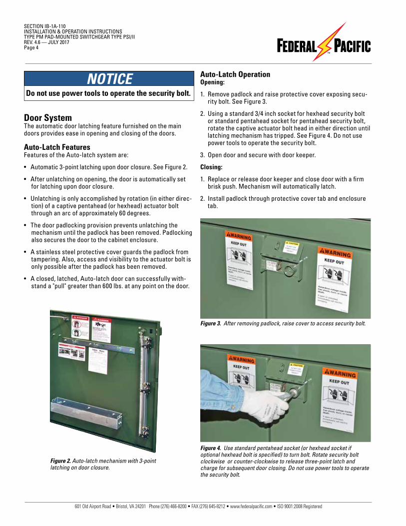
Door SystemThe automatic door latching feature furnished on the main doors provides ease in opening and closing of the doors.
Auto-Latch FeaturesFeatures of the Auto-latch system are:
• Automatic 3-point latching upon door closure. See Figure 2.
• After unlatching on opening, the door is automatically set for latching upon door closure.
• Unlatching is only accomplished by rotation (in either direc-tion) of a captive pentahead (or hexhead) actuator bolt through an arc of approximately 60 degrees.
• The door padlocking provision prevents unlatching the mechanism until the padlock has been removed. Padlocking also secures the door to the cabinet enclosure.
• A stainless steel protective cover guards the padlock from tampering. Also, access and visibility to the actuator bolt is only possible after the padlock has been removed.
• A closed, latched, Auto-latch door can successfully with-stand a "pull" greater than 600 lbs. at any point on the door.
Figure 2. Auto-latch mechanism with 3-point latching on door closure.
Auto-Latch OperationOpening:
1. Remove padlock and raise protective cover exposing secu-rity bolt. See Figure 3.
2. Using a standard 3/4 inch socket for hexhead security bolt or standard pentahead socket for pentahead security bolt, rotate the captive actuator bolt head in either direction until latching mechanism has tripped. See Figure 4. Do not use power tools to operate the security bolt.
3. Open door and secure with door keeper.
Closing:
1. Replace or release door keeper and close door with a firm brisk push. Mechanism will automatically latch.
2. Install padlock through protective cover tab and enclosure tab.
Figure 3. After removing padlock, raise cover to access security bolt.
Figure 4. Use standard pentahead socket (or hexhead socket if optional hexhead bolt is specified) to turn bolt. Rotate security bolt clockwise or counter-clockwise to release three-point latch and charge for subsequent door closing. Do not use power tools to operate the security bolt.
NOTICEDo not use power tools to operate the security bolt.
601 Old Airport Road • Bristol, VA 24201 Phone (276) 466-8200 • FAX (276) 645-8212 • www.federalpacific.com • ISO 9001:2008 Registered
SECTION IB-1A-110INSTALLATION & OPERATION INSTRUCTIONS
PAD-MOUNTED SWITCHGEAR TYPE PSI/IIREV. 4.6 — JULY 2017
Page 5
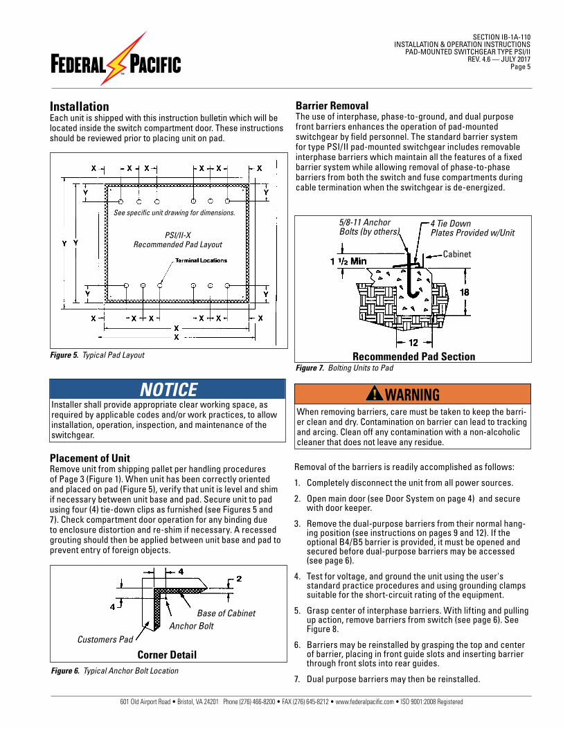
InstallationEach unit is shipped with this instruction bulletin which will be located inside the switch compartment door. These instructions should be reviewed prior to placing unit on pad.
Figure 5. Typical Pad Layout
Placement of UnitRemove unit from shipping pallet per handling procedures of Page 3 (Figure 1). When unit has been correctly oriented and placed on pad (Figure 5), verify that unit is level and shim if necessary between unit base and pad. Secure unit to pad using four (4) tie-down clips as furnished (see Figures 5 and 7). Check compartment door operation for any binding due to enclosure distortion and re-shim if necessary. A recessed grouting should then be applied between unit base and pad to prevent entry of foreign objects.
Barrier RemovalThe use of interphase, phase-to-ground, and dual purpose front barriers enhances the operation of pad-mounted switchgear by field personnel. The standard barrier system for type PSI/II pad-mounted switchgear includes removable interphase barriers which maintain all the features of a fixed barrier system while allowing removal of phase-to-phase barriers from both the switch and fuse compartments during cable termination when the switchgear is de-energized.
Figure 6. Typical Anchor Bolt Location
Corner Detail
Base of CabinetAnchor Bolt
Customers Pad
PSI/II-XRecommended Pad Layout
See specific unit drawing for dimensions.
Removal of the barriers is readily accomplished as follows:
1. Completely disconnect the unit from all power sources.
2. Open main door (see Door System on page 4) and secure with door keeper.
3. Remove the dual-purpose barriers from their normal hang-ing position (see instructions on pages 9 and 12). If the optional B4/B5 barrier is provided, it must be opened and secured before dual-purpose barriers may be accessed (see page 6).
4. Test for voltage, and ground the unit using the user's standard practice procedures and using grounding clamps suitable for the short-circuit rating of the equipment.
5. Grasp center of interphase barriers. With lifting and pulling up action, remove barriers from switch (see page 6). See Figure 8.
6. Barriers may be reinstalled by grasping the top and center of barrier, placing in front guide slots and inserting barrier through front slots into rear guides.
7. Dual purpose barriers may then be reinstalled.
When removing barriers, care must be taken to keep the barri-er clean and dry. Contamination on barrier can lead to tracking and arcing. Clean off any contamination with a non-alcoholic cleaner that does not leave any residue.
WARNING
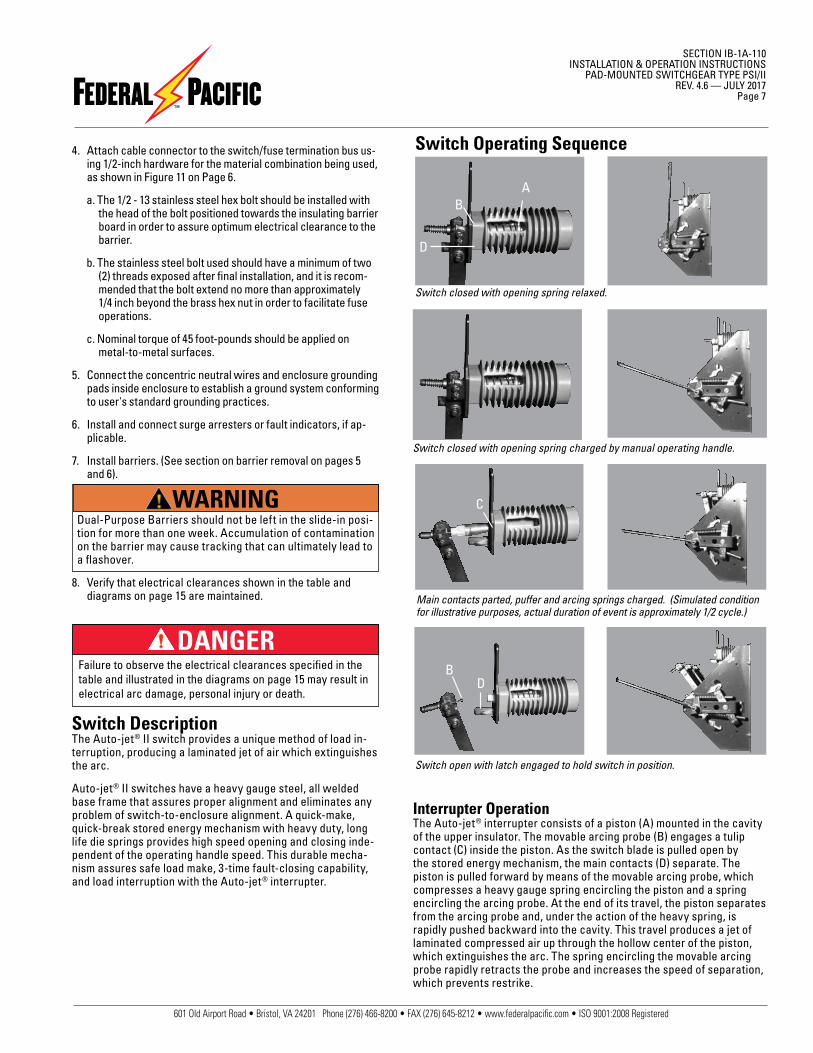
Figure 7. Bolting Units to Pad
Cabinet
Recommended Pad Section
4 Tie DownPlates Provided w/Unit
Cabinet
5/8-11 AnchorBolts (by others)
NOTICEInstaller shall provide appropriate clear working space, as required by applicable codes and/or work practices, to allow installation, operation, inspection, and maintenance of the switchgear.

601 Old Airport Road • Bristol, VA 24201 Phone (276) 466-8200 • FAX (276) 645-8212 • www.federalpacific.com • ISO 9001:2008 Registered
SECTION IB-1A-110INSTALLATION & OPERATION INSTRUCTIONSTYPE PM PAD-MOUNTED SWITCHGEAR TYPE PSI/IIREV. 4.6 — JULY 2017Page 6
Figure 11. Hardware for termination connection
Figure 8. Switch and fuse side removable barriers facilitate cable installation and termination when the switchgear is de-energized. Fuse side is shown. Lift up until rivets on barrier align with slot in top front barrier guide, and pull out to remove barriers.
Securing Optional B4/B5 Barriers OpenThe optional B4/B5 hinged barrier is provided to meet the requirements of section 381-G of the National Electrical Safety Code. The B4/B5 barrier (if provided) may be opened and secured as follows:
1. Disengage the security bolts that secure the B4/B5 barriers. See Figure 9.
2. Pivot the hinged barrier open. Secure the barrier open by sliding the pin on the enclosure-door tab into the clip on the top edge of the bar-rier. See Figure 10.
3. B4/B5 barrier may be closed and secured by reversing the steps above.
Customer Cable ConnectionsWith removable barriers removed, customer cables may be easily terminated per the following procedures:
1. The hanging weight of the primary cables must not be allowed to place undue strain on the switch/fuse termination bus. Should this situation exist, cable supports must be used. The mounting holes in the switch/fuse termination bus and the cable connector must align to prevent undue strain.
2. Make up the primary cable connections per user URD operating procedures, cable manufacturer instructions, and cable terminator manufacturer instructions.
Figure 9. Disengage barrier security bolt.
Figure 10. Secure barrier open.
1/2 - 13 BrassHex Nut
1/2 Stainless SteelSplit Lock Washer
1/2 Stainless SteelFlat Washer
1/2 - 13 StainlessSteel Hex Bolt
1/2 Stainless SteelFlat Washer
CU-CU
1/2 - 13 BrassHex Nut
1/2 Stainless SteelBelleville Lock Washer
1/2 Stainless SteelFlat Washer
1/2 - 13 StainlessSteel Hex Bolt
1/2 Stainless SteelFlat Washer
CU-AL
1/2 - 13 BrassHex Nut
1/2 Stainless SteelBelleville Lock Washer
1/2 Stainless SteelFlat Washer
1/2 - 13 StainlessSteel Hex Bolt
1/2 Stainless SteelFlat Washer
AL-AL
1/2 Stainless SteelBelleville Lock Washer
3. Remove surface oxides and coat both surfaces with suitable joint compound (required only when unplated aluminum connectors are used).
DANGERFailure to observe the electrical clearances specified in the table and illustrated in the diagrams on page 15 may result in electrical arc damage, personal injury or death.
The maximum momentary rating of the switchgear must be consid-ered when selecting cable size for connecting switchgear to system ground. Refer to unit rating plate.
WARNING
CAUTIONWhen terminating cables, ensure that each cable termination con-nector lays flat against the corresponding switch or fuse terminal, so that no additional strain is put on the terminal and the corresponding bolt holes are in alignment. The connecting bolts are not to be used to pull the cable terminations into alignment with the terminals.
601 Old Airport Road • Bristol, VA 24201 Phone (276) 466-8200 • FAX (276) 645-8212 • www.federalpacific.com • ISO 9001:2008 Registered
SECTION IB-1A-110INSTALLATION & OPERATION INSTRUCTIONS
PAD-MOUNTED SWITCHGEAR TYPE PSI/IIREV. 4.6 — JULY 2017
Page 7
4. Attach cable connector to the switch/fuse termination bus us-ing 1/2-inch hardware for the material combination being used, as shown in Figure 11 on Page 6.
a. The 1/2 - 13 stainless steel hex bolt should be installed with the head of the bolt positioned towards the insulating barrier board in order to assure optimum electrical clearance to the barrier.
b. The stainless steel bolt used should have a minimum of two (2) threads exposed after final installation, and it is recom-mended that the bolt extend no more than approximately 1/4 inch beyond the brass hex nut in order to facilitate fuse operations.
c. Nominal torque of 45 foot-pounds should be applied on metal-to-metal surfaces.
5. Connect the concentric neutral wires and enclosure grounding pads inside enclosure to establish a ground system conforming to user's standard grounding practices.
6. Install and connect surge arresters or fault indicators, if ap-plicable.
7. Install barriers. (See section on barrier removal on pages 5 and 6).
Dual-Purpose Barriers should not be left in the slide-in posi-tion for more than one week. Accumulation of contamination on the barrier may cause tracking that can ultimately lead to a flashover.
8. Verify that electrical clearances shown in the table and diagrams on page 15 are maintained.
Failure to observe the electrical clearances specified in the table and illustrated in the diagrams on page 15 may result in electrical arc damage, personal injury or death.
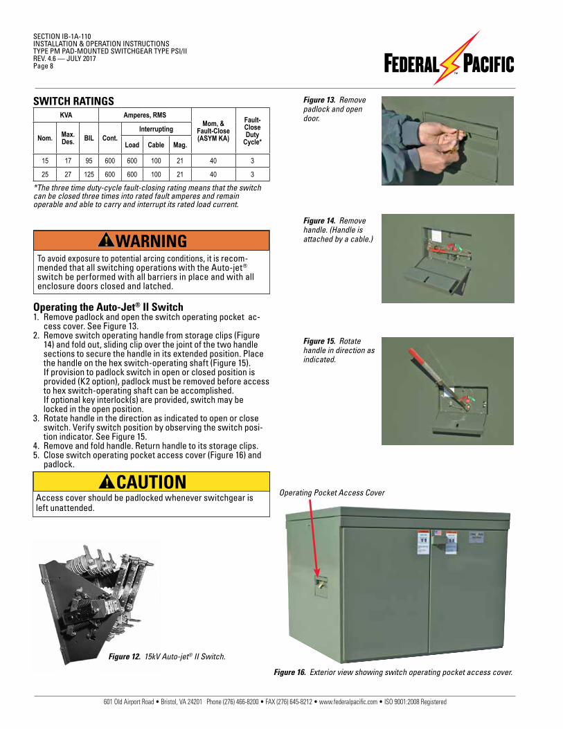
Switch DescriptionThe Auto-jet® II switch provides a unique method of load in-terruption, producing a laminated jet of air which extinguishes the arc.
Auto-jet® II switches have a heavy gauge steel, all welded base frame that assures proper alignment and eliminates any problem of switch-to-enclosure alignment. A quick-make, quick-break stored energy mechanism with heavy duty, long life die springs provides high speed opening and closing inde-pendent of the operating handle speed. This durable mecha-nism assures safe load make, 3-time fault-closing capability, and load interruption with the Auto-jet® interrupter.
Interrupter OperationThe Auto-jet® interrupter consists of a piston (A) mounted in the cavity of the upper insulator. The movable arcing probe (B) engages a tulip contact (C) inside the piston. As the switch blade is pulled open by the stored energy mechanism, the main contacts (D) separate. The piston is pulled forward by means of the movable arcing probe, which compresses a heavy gauge spring encircling the piston and a spring encircling the arcing probe. At the end of its travel, the piston separates from the arcing probe and, under the action of the heavy spring, is rapidly pushed backward into the cavity. This travel produces a jet of laminated compressed air up through the hollow center of the piston, which extinguishes the arc. The spring encircling the movable arcing probe rapidly retracts the probe and increases the speed of separation, which prevents restrike.
Switch open with latch engaged to hold switch in position.
Switch closed with opening spring relaxed.
Switch closed with opening spring charged by manual operating handle.
Main contacts parted, puffer and arcing springs charged. (Simulated condition for illustrative purposes, actual duration of event is approximately 1/2 cycle.)
A
D
B
DB
C
Switch Operating Sequence
DANGER
WARNING
601 Old Airport Road • Bristol, VA 24201 Phone (276) 466-8200 • FAX (276) 645-8212 • www.federalpacific.com • ISO 9001:2008 Registered
SECTION IB-1A-110INSTALLATION & OPERATION INSTRUCTIONSTYPE PM PAD-MOUNTED SWITCHGEAR TYPE PSI/IIREV. 4.6 — JULY 2017Page 8
Operating the Auto-Jet® II Switch1. Remove padlock and open the switch operating pocket ac-
cess cover. See Figure 13.2. Remove switch operating handle from storage clips (Figure
14) and fold out, sliding clip over the joint of the two handle sections to secure the handle in its extended position. Place the handle on the hex switch-operating shaft (Figure 15). If provision to padlock switch in open or closed position is provided (K2 option), padlock must be removed before access to hex switch-operating shaft can be accomplished.
If optional key interlock(s) are provided, switch may be locked in the open position.
3. Rotate handle in the direction as indicated to open or close switch. Verify switch position by observing the switch posi-tion indicator. See Figure 15.
4. Remove and fold handle. Return handle to its storage clips.5. Close switch operating pocket access cover (Figure 16) and
padlock.
Access cover should be padlocked whenever switchgear is left unattended.
Figure 16. Exterior view showing switch operating pocket access cover.
Figure 13. Remove padlock and open door.
Figure 14. Remove handle. (Handle is attached by a cable.)
Figure 15. Rotate handle in direction as indicated.
Figure 12. 15kV Auto-jet® II Switch.
SWITCH RATINGS
*The three time duty-cycle fault-closing rating means that the switch can be closed three times into rated fault amperes and remain operable and able to carry and interrupt its rated load current.
KVA Amperes, RMSMom, &
Fault-Close(ASYM KA)
Fault-CloseDuty
Cycle*Nom. Max.Des. BIL Cont.
Interrupting
Load Cable Mag.
15 17 95 600 600 100 21 40 3
25 27 125 600 600 100 21 40 3
Operating Pocket Access CoverCAUTION
WARNINGTo avoid exposure to potential arcing conditions, it is recom-mended that all switching operations with the Auto-jet® switch be performed with all barriers in place and with all enclosure doors closed and latched.
601 Old Airport Road • Bristol, VA 24201 Phone (276) 466-8200 • FAX (276) 645-8212 • www.federalpacific.com • ISO 9001:2008 Registered
SECTION IB-1A-110INSTALLATION & OPERATION INSTRUCTIONS
PAD-MOUNTED SWITCHGEAR TYPE PSI/IIREV. 4.6 — JULY 2017
Page 9
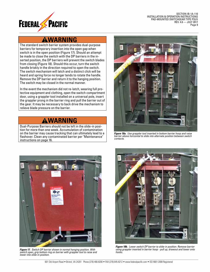
Figure 17. Switch DP barrier shown in normal hanging position. With switch open, grip bottom ring on barrier with grappler tool to raise and lower into slide-in position.
Figure 18b. Lower switch DP barrier to slide-in position. Remove barrier using grappler inserted in barrier hoop - pull up, drawout and lower onto hooks.
Figure 18a. Use grappler tool inserted in bottom barrier hoop and raise barrier above horizontal to slide into alternate position between switch contacts.
The standard switch barrier system provides dual-purpose barriers for temporary insertion into the open gap when switch is in the open position (Figure 17). Should an attempt be made to close the switch with the DP barriers in the in-serted position, the DP barriers will prevent the switch blades from closing (Figure 18). Should this occur, turn the switch handle briskly in the direction required to open the switch. The switch mechanism will latch and a distinct click will be heard and spring force no longer tends to rotate the handle. Remove the DP barrier and return it to the hanging position. The switch may be closed in the normal manner.
In the event the mechanism did not re-latch, wearing full pro-tective equipment and clothing, open the switch compartment door, using a grappler tool installed on a universal pole, insert the grappler prong in the barrier ring and pull the barrier out of the gear. It may be necessary to back drive the mechanism to relieve blade pressure on the barrier.
Dual-Purpose Barriers should not be left in the slide-in posi-tion for more than one week. Accumulation of contamination on the barrier may cause tracking that can ultimately lead to a flashover. Clean any contaminated barrier per "Maintenance" instructions on page 16.
WARNING
WARNING
601 Old Airport Road • Bristol, VA 24201 Phone (276) 466-8200 • FAX (276) 645-8212 • www.federalpacific.com • ISO 9001:2008 Registered
SECTION IB-1A-110INSTALLATION & OPERATION INSTRUCTIONSTYPE PM PAD-MOUNTED SWITCHGEAR TYPE PSI/IIREV. 4.6 — JULY 2017Page 10
The fuse assembly must be in the proper latched position with the contact rod on the upper fuse end fitting engaging the latch face during the closing operation (see "Preliminary Check Before Energizing") and secured behind the latch face after complete closure has been achieved. In addition, the fingers of the fuse end fittings must be fully positioned behind the black latch housing and the Positive Latch Indicator extended. See Figure 23(b). This allows the interrupter to function properly so that as the fuseholder is pulled (see Figure 26), the interrupting plunger will be pulled forward with it. See Figure 27. The arc is then extinguished safely and properly by the puffer mechanism before the fuseholder breaks free of the receiver. See Figure 28.
1. If the contact rod does not engage the latch face, the interrupting floating contact assembly will not be pulled forward. If this is the case, the fuse assembly may not be correctly assembled or the hinge assembly may be posi-tioned too low.
2. Examine the fuse assembly and confirm that it is correctly assembled in accordance with the fuse manufacturer's instructions.
3. Inspect the fuse mounting and verify that all bolts are se-cure and that the fuse assembly properly fits into the hinge assembly.
4. If the fuseholder is not in the properly latched position, the top of the fuse barrel will not have been pushed far enough forward into the receiver for the end-fitting fingers to be caught by the receiver housing and the Positive Latch Indicator is not extended (see Figure 29). When this is the case, if the fuseholder is pulled open (see Figure 30), the interrupter mechanism may not be pulled forward with it and, therefore, may not extinguish the arc. This could result in a flashover. DO NOT ATTEMPT TO OPEN A FUSE THAT IS NOT COMPLETELY LATCHED!
The Auto-jet® fuse mounting has an integral loadbreak device that permits single-pole live switching in single-phase or three-phase circuits by the use of an ordinary universal pole equipped with a grappler. The integral loadbreak device has a 3-time fault close duty-cycle when the fuse is closed briskly without hesitation. The overall unit rating may be limited by the fuse rating.
The same unique laminated air jet interrupter system used in the 3-pole group-operated switches is applied in the Auto-jet® loadbreak fuse mountings.
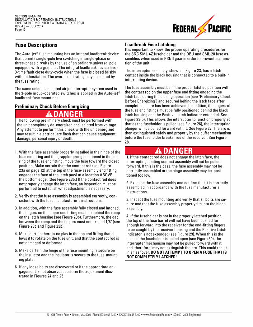
Preliminary Check Before Energizing
The following preliminary check must be performed with the unit completely de-energized and isolated from voltage. Any attempt to perform this check with the unit energized may result in electrical arc flash that can cause equipment damage, personal injury or death.
1. With the fuse assembly properly installed in the hinge of the fuse mounting and the grappler prong positioned in the pull ring of the fuse end fitting, move the fuse toward the closed position. Make certain that the contact rod (see Figure 23a on page 12) at the top of the fuse-assembly end fitting engages the face of the latch pawl at a location ABOVE the bottom edge. (See Figure 23b.) If the contact rod does not properly engage the latch face, an inspection must be performed to establish what adjustment is necessary.
2. Verify that the fuse assembly is assembled correctly, con-sistent with the fuse manufacturer's instructions.
3. In addition, with the fuse assembly fully closed and latched, the fingers on the upper end fitting must be behind the ramp on the latch housing (see Figure 23b). Furthermore, the gap between the ramp and the fingers must not exceed 1/8" (see Figure 23c and Figure 23b).
4. Make certain there is no play in the top end fitting that al-lows it to rotate on the fuse unit, and that the contact rod is not damaged or deformed.
5. Make certain the hinge of the fuse mounting is secure on the insulator and the insulator is secure to the fuse-mount-ing plate.
6. If any loose bolts are discovered or if the appropriate en-gagement is not observed, perform the adjustment illus-trated in Figures 24 and 25.
Fuse Descriptions Loadbreak Fuse LatchingIt is important to know the proper operating procedures for the S&C SML-4Z fuseholder and the DBU and SML-20 fuse as-semblies when used in PSI/II gear in order to prevent malfunc-tion of the unit.
The interrupter assembly, shown in Figure 23, has a latch contact inside the black housing that is connected to a built-in interrupting device.
DANGER
DANGER
601 Old Airport Road • Bristol, VA 24201 Phone (276) 466-8200 • FAX (276) 645-8212 • www.federalpacific.com • ISO 9001:2008 Registered
SECTION IB-1A-110INSTALLATION & OPERATION INSTRUCTIONS
PAD-MOUNTED SWITCHGEAR TYPE PSI/IIREV. 4.6 — JULY 2017
Page 11
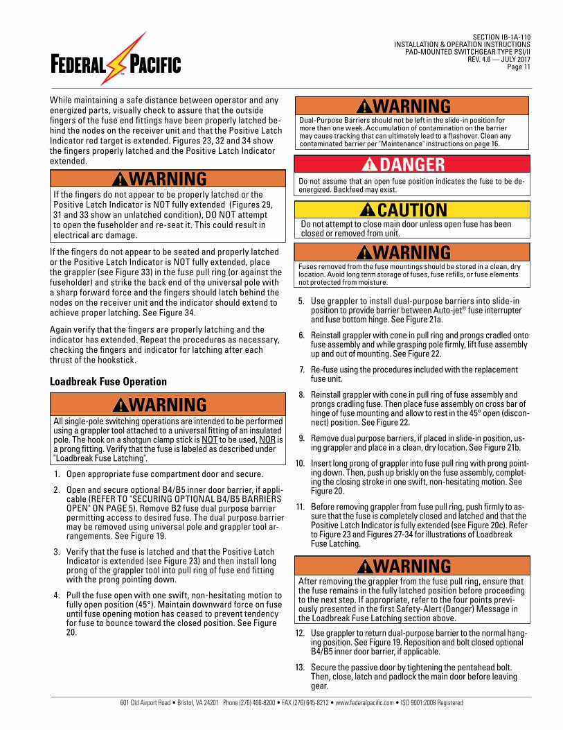
Loadbreak Fuse Operation
All single-pole switching operations are intended to be performed using a grappler tool attached to a universal fitting of an insulated pole. The hook on a shotgun clamp stick is NOT to be used, NOR is a prong fitting. Verify that the fuse is labeled as described under "Loadbreak Fuse Latching".
1. Open appropriate fuse compartment door and secure.
2. Open and secure optional B4/B5 inner door barrier, if appli-cable (REFER TO "SECURING OPTIONAL B4/B5 BARRIERS OPEN" ON PAGE 5). Remove B2 fuse dual purpose barrier permitting access to desired fuse. The dual purpose barrier may be removed using universal pole and grappler tool ar-rangements. See Figure 19.
3. Verify that the fuse is latched and that the Positive Latch Indicator is extended (see Figure 23) and then install long prong of the grappler tool into pull ring of fuse end fitting with the prong pointing down.
4. Pull the fuse open with one swift, non-hesitating motion to fully open position (45°). Maintain downward force on fuse until fuse opening motion has ceased to prevent tendency for fuse to bounce toward the closed position. See Figure 20.
While maintaining a safe distance between operator and any energized parts, visually check to assure that the outside fingers of the fuse end fittings have been properly latched be-hind the nodes on the receiver unit and that the Positive Latch Indicator red target is extended. Figures 23, 32 and 34 show the fingers properly latched and the Positive Latch Indicator extended.
If the fingers do not appear to be properly latched or the Positive Latch Indicator is NOT fully extended (Figures 29, 31 and 33 show an unlatched condition), DO NOT attempt to open the fuseholder and re-seat it. This could result in electrical arc damage.
If the fingers do not appear to be seated and properly latched or the Positive Latch Indicator is NOT fully extended, place the grappler (see Figure 33) in the fuse pull ring (or against the fuseholder) and strike the back end of the universal pole with a sharp forward force and the fingers should latch behind the nodes on the receiver unit and the indicator should extend to achieve proper latching. See Figure 34.
Again verify that the fingers are properly latching and the indicator has extended. Repeat the procedures as necessary, checking the fingers and indicator for latching after each thrust of the hookstick.
5. Use grappler to install dual-purpose barriers into slide-in position to provide barrier between Auto-jet® fuse interrupter and fuse bottom hinge. See Figure 21a.
6. Reinstall grappler with cone in pull ring and prongs cradled onto fuse assembly and while grasping pole firmly, lift fuse assembly up and out of mounting. See Figure 22.
7. Re-fuse using the procedures included with the replacement fuse unit.
8. Reinstall grappler with cone in pull ring of fuse assembly and prongs cradling fuse. Then place fuse assembly on cross bar of hinge of fuse mounting and allow to rest in the 45° open (discon-nect) position. See Figure 22.
9. Remove dual purpose barriers, if placed in slide-in position, us-ing grappler and place in a clean, dry location. See Figure 21b.
10. Insert long prong of grappler into fuse pull ring with prong point-ing down. Then, push up briskly on the fuse assembly, complet-ing the closing stroke in one swift, non-hesitating motion. See Figure 20.
11. Before removing grappler from fuse pull ring, push firmly to as-sure that the fuse is completely closed and latched and that the Positive Latch Indicator is fully extended (see Figure 20c). Refer to Figure 23 and Figures 27-34 for illustrations of Loadbreak Fuse Latching.
12. Use grappler to return dual-purpose barrier to the normal hang-ing position. See Figure 19. Reposition and bolt closed optional B4/B5 inner door barrier, if applicable.
13. Secure the passive door by tightening the pentahead bolt. Then, close, latch and padlock the main door before leaving gear.
WARNING
WARNING
Dual-Purpose Barriers should not be left in the slide-in position for more than one week. Accumulation of contamination on the barrier may cause tracking that can ultimately lead to a flashover. Clean any contaminated barrier per "Maintenance" instructions on page 16.
WARNING
Do not assume that an open fuse position indicates the fuse to be de-energized. Backfeed may exist.
DANGER
Fuses removed from the fuse mountings should be stored in a clean, dry location. Avoid long term storage of fuses, fuse refills, or fuse elements not protected from moisture.
WARNING
CAUTION Do not attempt to close main door unless open fuse has been closed or removed from unit.
WARNINGAfter removing the grappler from the fuse pull ring, ensure that the fuse remains in the fully latched position before proceeding to the next step. If appropriate, refer to the four points previ-ously presented in the first Safety-Alert (Danger) Message in the Loadbreak Fuse Latching section above.
601 Old Airport Road • Bristol, VA 24201 Phone (276) 466-8200 • FAX (276) 645-8212 • www.federalpacific.com • ISO 9001:2008 Registered
SECTION IB-1A-110INSTALLATION & OPERATION INSTRUCTIONSTYPE PM PAD-MOUNTED SWITCHGEAR TYPE PSI/IIREV. 4.6 — JULY 2017Page 12
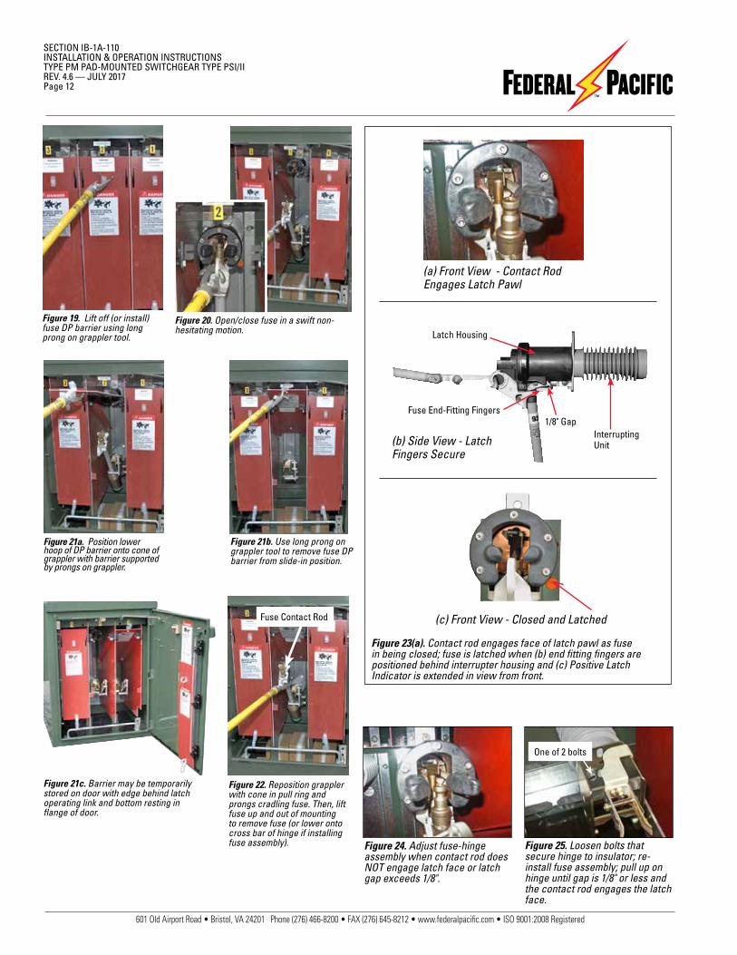
Figure 19. Lift off (or install) fuse DP barrier using long prong on grappler tool.
Figure 20. Open/close fuse in a swift non-hesitating motion.
Figure 21b. Use long prong on grappler tool to remove fuse DP barrier from slide-in position.
Figure 22. Reposition grappler with cone in pull ring and prongs cradling fuse. Then, lift fuse up and out of mounting to remove fuse (or lower onto cross bar of hinge if installing fuse assembly).
Figure 23(a). Contact rod engages face of latch pawl as fuse in being closed; fuse is latched when (b) end fitting fingers are positioned behind interrupter housing and (c) Positive Latch Indicator is extended in view from front.
Figure 21a. Position lower hoop of DP barrier onto cone of grappler with barrier supported by prongs on grappler.
Figure 24. Adjust fuse-hinge assembly when contact rod does NOT engage latch face or latch gap exceeds 1/8".
Figure 25. Loosen bolts that secure hinge to insulator; re-install fuse assembly; pull up on hinge until gap is 1/8" or less and the contact rod engages the latch face.
(c) Front View - Closed and Latched
(a) Front View - Contact RodEngages Latch Pawl
Interrupting Unit(b) Side View - Latch
Fingers Secure
Latch Housing
Fuse End-Fitting Fingers1/8" Gap
One of 2 bolts
Fuse Contact Rod
Figure 21c. Barrier may be temporarily stored on door with edge behind latch operating link and bottom resting in flange of door.

601 Old Airport Road • Bristol, VA 24201 Phone (276) 466-8200 • FAX (276) 645-8212 • www.federalpacific.com • ISO 9001:2008 Registered
SECTION IB-1A-110INSTALLATION & OPERATION INSTRUCTIONS
PAD-MOUNTED SWITCHGEAR TYPE PSI/IIREV. 4.6 — JULY 2017
Page 13
1. All upstream devices which could energize the fuse must be opened and rendered de-energized to remove possibility of inadvertently energizing the fuse.
2. Upon opening the fuse compartment door, the equipment should be tested for the presence of voltage using a suitable voltage sensing device installed on a universal pole.
3. If no voltage is present, the appropriate fuse terminal should be grounded using proper grounding techniques and de-vices.
4. Fuse(s) may then be removed and replaced using the user's appropriate standard fuse replacement procedures.
Non-Loadbreak Fuse OperationWhen non-loadbreak style fuse mountings are furnished, such as the clip style mountings to accommodate Cooper (McGraw-Edison) Type NX and Kearney Type Q, the fuse replacement procedure would be similar to those for the Auto-jet® loadbreak fuses. However, the following precautions should be observed when work is performed on non-loadbreak fuses:
Figure 26. Fuseholder being removed.
Figure 29. Unlatched condition and latch indicator NOT extended.
Figure 30. Fuseholder being opened.
Figure 31. Unlatched. Figure 32. Latched and indicator extended.
Figure 27. Contacts extending.
Figure 28. Full open.
Figure 33. Unlatched. Figure 34. Latched and indicator extended.
Loadbreak Fuse Operating Sequence
DANGERDo not open non-loadbreak style fuse mountings or otherwise attempt to disconnect such fuses when the circuit is energized.
601 Old Airport Road • Bristol, VA 24201 Phone (276) 466-8200 • FAX (276) 645-8212 • www.federalpacific.com • ISO 9001:2008 Registered
SECTION IB-1A-110INSTALLATION & OPERATION INSTRUCTIONSTYPE PM PAD-MOUNTED SWITCHGEAR TYPE PSI/IIREV. 4.6 — JULY 2017Page 14
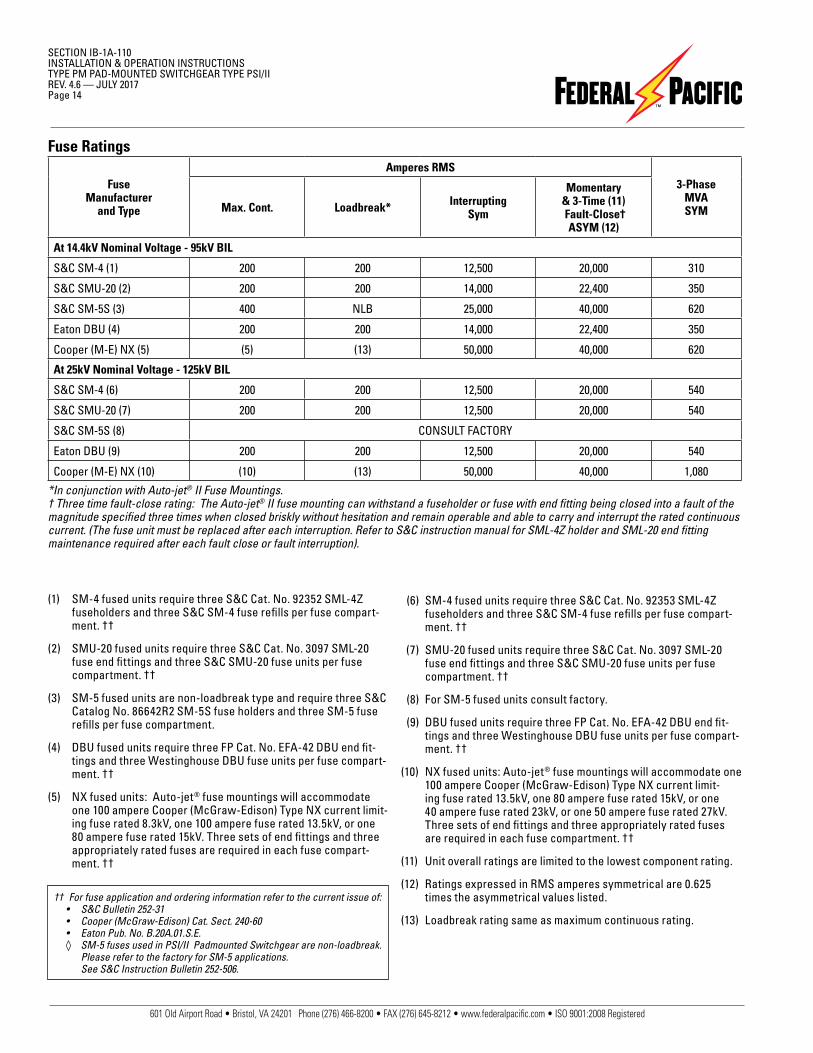
Fuse Ratings
*In conjunction with Auto-jet® II Fuse Mountings.† Three time fault-close rating: The Auto-jet® II fuse mounting can withstand a fuseholder or fuse with end fitting being closed into a fault of the magnitude specified three times when closed briskly without hesitation and remain operable and able to carry and interrupt the rated continuous current. (The fuse unit must be replaced after each interruption. Refer to S&C instruction manual for SML-4Z holder and SML-20 end fitting maintenance required after each fault close or fault interruption).
(1) SM-4 fused units require three S&C Cat. No. 92352 SML-4Z fuseholders and three S&C SM-4 fuse refills per fuse compart-ment. ††
(2) SMU-20 fused units require three S&C Cat. No. 3097 SML-20 fuse end fittings and three S&C SMU-20 fuse units per fuse compartment. ††
(3) SM-5 fused units are non-loadbreak type and require three S&C Catalog No. 86642R2 SM-5S fuse holders and three SM-5 fuse refills per fuse compartment.
(4) DBU fused units require three FP Cat. No. EFA-42 DBU end fit-tings and three Westinghouse DBU fuse units per fuse compart-ment. ††
(5) NX fused units: Auto-jet® fuse mountings will accommodate one 100 ampere Cooper (McGraw-Edison) Type NX current limit-ing fuse rated 8.3kV, one 100 ampere fuse rated 13.5kV, or one 80 ampere fuse rated 15kV. Three sets of end fittings and three appropriately rated fuses are required in each fuse compart-ment. ††
(6) SM-4 fused units require three S&C Cat. No. 92353 SML-4Z fuseholders and three S&C SM-4 fuse refills per fuse compart-ment. ††
(7) SMU-20 fused units require three S&C Cat. No. 3097 SML-20 fuse end fittings and three S&C SMU-20 fuse units per fuse compartment. ††
(8) For SM-5 fused units consult factory.
(9) DBU fused units require three FP Cat. No. EFA-42 DBU end fit-tings and three Westinghouse DBU fuse units per fuse compart-ment. ††
(10) NX fused units: Auto-jet® fuse mountings will accommodate one 100 ampere Cooper (McGraw-Edison) Type NX current limit-ing fuse rated 13.5kV, one 80 ampere fuse rated 15kV, or one 40 ampere fuse rated 23kV, or one 50 ampere fuse rated 27kV. Three sets of end fittings and three appropriately rated fuses are required in each fuse compartment. ††
(11) Unit overall ratings are limited to the lowest component rating.
(12) Ratings expressed in RMS amperes symmetrical are 0.625 times the asymmetrical values listed.
(13) Loadbreak rating same as maximum continuous rating.
Fuse Manufacturer
and Type
Amperes RMS3-Phase
MVASYMMax. Cont. Loadbreak* Interrupting
Sym
Momentary & 3-Time (11) Fault-Close†
ASYM (12)
At 14.4kV Nominal Voltage - 95kV BIL
S&C SM-4 (1) 200 200 12,500 20,000 310
S&C SMU-20 (2) 200 200 14,000 22,400 350
S&C SM-5S (3) 400 NLB 25,000 40,000 620
Eaton DBU (4) 200 200 14,000 22,400 350
Cooper (M-E) NX (5) (5) (13) 50,000 40,000 620
At 25kV Nominal Voltage - 125kV BIL
S&C SM-4 (6) 200 200 12,500 20,000 540
S&C SMU-20 (7) 200 200 12,500 20,000 540
S&C SM-5S (8) CONSULT FACTORY
Eaton DBU (9) 200 200 12,500 20,000 540
Cooper (M-E) NX (10) (10) (13) 50,000 40,000 1,080
†† For fuse application and ordering information refer to the current issue of: • S&C Bulletin 252-31 • Cooper (McGraw-Edison) Cat. Sect. 240-60 • Eaton Pub. No. B.20A.01.S.E. ◊ SM-5 fuses used in PSI/II Padmounted Switchgear are non-loadbreak.
Please refer to the factory for SM-5 applications. See S&C Instruction Bulletin 252-506.
601 Old Airport Road • Bristol, VA 24201 Phone (276) 466-8200 • FAX (276) 645-8212 • www.federalpacific.com • ISO 9001:2008 Registered
SECTION IB-1A-110INSTALLATION & OPERATION INSTRUCTIONS
PAD-MOUNTED SWITCHGEAR TYPE PSI/IIREV. 4.6 — JULY 2017
Page 15
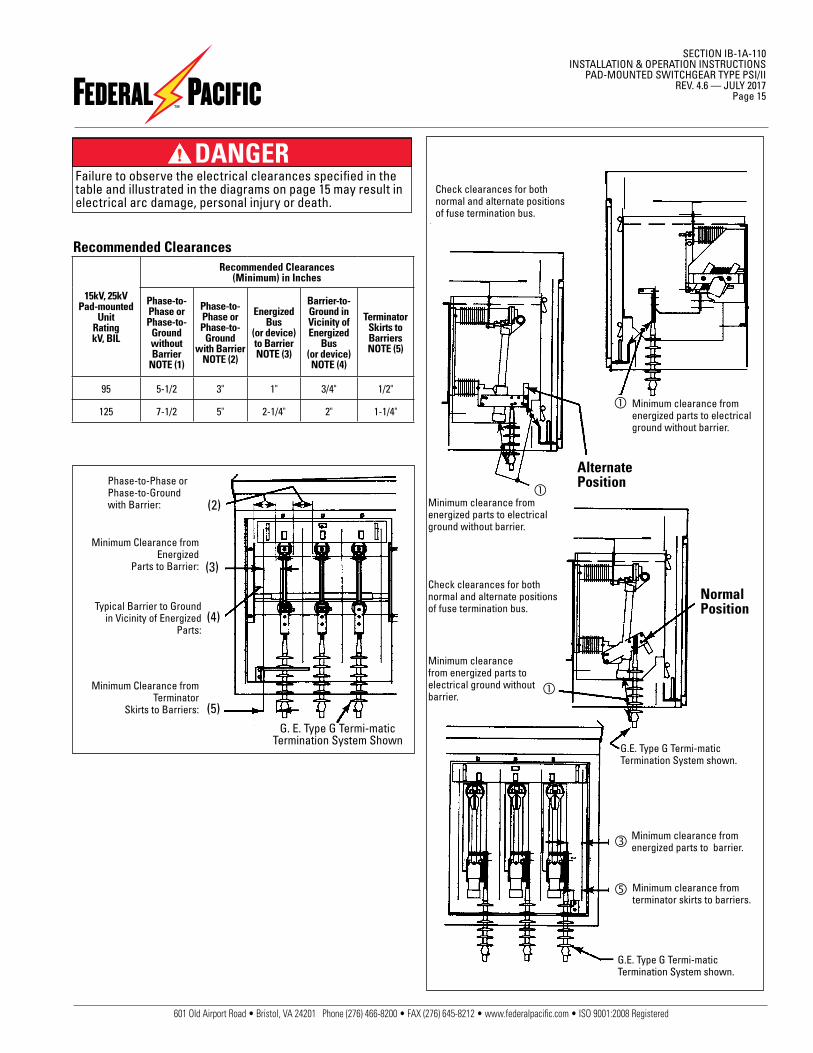
Check clearances for both normal and alternate positions of fuse termination bus.
Minimum clearance from energized parts to electrical ground without barrier.
Minimum clearance from energized parts to electrical ground without barrier.
Check clearances for both normal and alternate positions of fuse termination bus.
Minimum clearance from energized parts to electrical ground without barrier.
G.E. Type G Termi-matic Termination System shown.
Minimum clearance from terminator skirts to barriers.
Minimum clearance from energized parts to barrier.
G.E. Type G Termi-matic Termination System shown.
NormalPosition
AlternatePosition
Recommended Clearances
15kV, 25kVPad-mounted
UnitRatingkV, BIL
Recommended Clearances(Minimum) in Inches
Phase-to-Phase or Phase-to-
Ground without Barrier
NOTE (1)
Phase-to-Phase or Phase-to-
Ground with Barrier
NOTE (2)
Energized Bus
(or device) to BarrierNOTE (3)
Barrier-to-Ground in Vicinity of Energized
Bus(or device)NOTE (4)
TerminatorSkirts to BarriersNOTE (5)
95 5-1/2 3" 1" 3/4" 1/2"
125 7-1/2 5" 2-1/4" 2" 1-1/4"
Minimum Clearance from Terminator
Skirts to Barriers:
Typical Barrier to Ground in Vicinity of Energized
Parts:
Minimum Clearance from Energized
Parts to Barrier:
Phase-to-Phase or Phase-to-Ground with Barrier:
(5)
(4)
(3)
(2)
G. E. Type G Termi-matic Termination System Shown
DANGERFailure to observe the electrical clearances specified in the table and illustrated in the diagrams on page 15 may result in electrical arc damage, personal injury or death.
601 Old Airport Road • Bristol, VA 24201 Phone (276) 466-8200 • FAX (276) 645-8212 • www.federalpacific.com • ISO 9001:2008 Registered
SECTION IB-1A-110INSTALLATION & OPERATION INSTRUCTIONSTYPE PM PAD-MOUNTED SWITCHGEAR TYPE PSI/IIREV. 4.6 — JULY 2017Page 16
MaintenanceFederal Pacific switchgear does not require routine mechani-cal or electrical maintenance. However, the following are some recommendations for enhancing continued service of the equip-ment.
1. Yearly mechanical exercising of the switch is recommended.
The switchgear must be completely de-energized from all sources before any attempt is made to enter switchgear.
2. Check for cleanliness generally, but particularly for accumula-tion of any foreign material on insulators and barriers.
Barriers and insulators can be cleaned with a non-alcohol based cleaner that does not leave any residue when dry. Residue must be removed.
Do not put any lubricant on switch probe or puffer.
3. If the switch is closed on a short circuit within the fault closing rating and the short circuit is cleared by circuit breakers or fuses, the switch will not sustain damage which would require major repairs. However, the switch should be inspected before returning to service to determine switch condition.
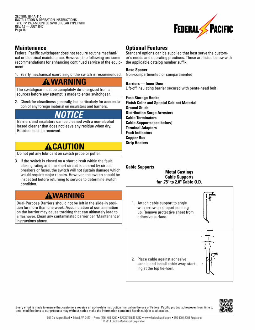
Cable SupportsMetal CastingsCable Supports
for .75" to 2.0" Cable O.D.
2. Place cable against adhesive saddle and install cable wrap start-ing at the top tie-horn.
1. Attach cable support to angle with arrow on support pointing up. Remove protective sheet from adhesive surface.
Optional FeaturesStandard options can be supplied that best serve the custom-er's needs and operating practices. These are listed below with the applicable catalog number suffix.
Base SpacerNon-compartmented or compartmented
Barriers — Inner DoorLift-off insulating barrier secured with penta-head bolt
Fuse Storage HooksFinish Color and Special Cabinet MaterialGround StudsDistribution Surge ArrestersCable TerminatorsCable Supports (see below)Terminal AdaptersFault IndicatorsCopper BusStrip Heaters
Every effort is made to ensure that customers receive an up-to-date instruction manual on the use of Federal Pacific products; however, from time to time, modifications to our products may without notice make the information contained herein subject to alteration.
NOTICE
© 2014 Electro-Mechanical Corporation
CAUTION
WARNING
WARNINGDual-Purpose Barriers should not be left in the slide-in posi-tion for more than one week. Accumulation of contamination on the barrier may cause tracking that can ultimately lead to a flashover. Clean any contaminated barrier per "Maintenance" instructions above.


![000 000 ï962-8601 TEL0248(88)8211 FAX 0248 (88) 8212 · 2020-04-07 · rt-3'I'ìžía-}] 135 0248-88-8211 [3 0248-94-7091 [4 0248-88-8212 HP :](https://img.pdfslide.us/doc/110x75/5f10e582f8d8fc13c51c7a74/000-000-962-8601-tel0248888211-fax-0248-88-8212-2020-04-07-rt-3ia-.jpg)