Embed Size (px)
Citation preview
i
If the outboard motor’s serial number plate contains the CE mark in the lowerleft‑hand corner, the following statement applies:This outboard motor manufactured by Mercury Marine, Fond du Lac, WI, USAor Marine Power Europe Inc. Park Industrel, de Petit‑Rechain, Belgiumcomplies with the requirements of the following directives and standards, asamended:
Recreational Craft Directive: 94/25/EC; std. ISO 8665, ISO11547
Machinery Directive: 98/37/EC,EMC Directive: 89/336/EC; std. EN50081‑1,
SAE J551 (CISPR Pub. 12), EN50082‑1, IEC 61000 PT4‑2, IEC61000 PT4‑3
Patrick C. MackeyPresident, Mercury Marine, Fond du Lac, WI USAEuropean Regulations Contact:Product Environmental Engineering Department, Mercury Marine,Fond du Lac, WI USA
EPA Emissions RegulationsOutboards manufactured by Mercury Marine in the United States arecertified to the United States Environmental Protection Agency asconforming to the requirements of the regulations for the control of airpollution from new outboard motors. This certification is contingent oncertain adjustments being set to factory standards. For this reason, thefactory procedure for servicing the product must be strictly followed and,wherever practicable, returned to the original intent of the design.Maintenance, replacement, or repair of the emission control devicesand systems may be performed by any marine engine repairestablishment or individual.Engines are labeled with an Emission Control Information decal aspermanent evidence of EPA certification.
! WARNINGThe engine exhaust from this product contains chemicals known tothe state of California to cause cancer, birth defects or otherreproductive harm. ©
200
5 M
ercu
ry M
arin
e25
0XS
Opt
iMax
90-8
4117
4060
505
ii
Thank Youfor your purchase of one of the finest outboards available. You have madea sound investment in boating pleasure. Your outboard has beenmanufactured by Mercury Marine, a world leader in marine technology andoutboard manufacturing since 1939. These years of experience have beencommitted to the goal of producing the finest quality products. This led toMercury Marine's reputation for strict quality control, excellence, durability,lasting performance and being the best at providing after the sale support.Please read this manual carefully before operating your outboard. Thismanual has been prepared to assist you in the operation, safe use and careof your outboard.All of us at Mercury Marine took pride in building your outboard and wishyou many years of happy and safe boating.Again, thank you for your confidence in Mercury Marine.
Warranty MessageThe product you have purchased comes with a limited warranty fromMercury Marine, the terms of the warranty are set forth in the WarrantyInformation Section of this manual. The warranty statement contains adescription of what is covered, what is not covered, the duration ofcoverage, how to best obtain warranty coverage, important disclaimers andlimitations of damages, and other related information. Please review thisimportant information.The description and specifications contained herein were in effect at thetime this manual was approved for printing. Mercury Marine, whose policyis one of continued improvement, reserves the right to discontinue modelsat any time, to change specifications, designs, methods, or procedureswithout notice and without incurring obligation.Mercury Marine, Fond du Lac, Wisconsin U.S.A.Litho in U.S.A.© 2005, Mercury MarineMercury, Mercury Marine, MerCruiser, Mercury MerCruiser, MercuryRacing, Mercury Precision Parts, Mercury Propellers, Mariner, Quicksilver,#1 On The Water, Alpha, Bravo, Pro Max, OptiMax, Sport‑Jet, K‑Planes,MerCathode, RideGuide, SmartCraft, Zero Effort, M with Waves logo,Mercury with Waves logo, and SmartCraft logo are all registeredtrademarks of Brunswick Corporation. Mercury Product Protection logo isa registered service mark of Brunswick Corporation.
iii
Mercury Premier ServiceMercury evaluates the service performance of its dealers and assigns itshighest rating of "Mercury Premier" to those demonstrating an exceptionalcommitment to service.Earning a Mercury Premier Service rating means a dealer:• Achieves a high 12 month service CSI (Customer Satisfaction Index)
score for warranty service.• Possesses all necessary service tools, test equipment, manuals and
parts books.• Employs at least one Certified or Master technician.• Provides timely service for all Mercury Marine customers.• Offers extended service hours and mobile service, when appropriate.• Uses, displays and stocks adequate inventory of genuine Mercury
Precision Parts.• Offers a clean, neat shop with well organized tools and service
literature.

iv
TABLE OF CONTENTS
v
Warranty Information
Warranty Registration United States And Canada...................................1Mercury Racing Demonstrator Policy.......................................................1Transfer Of Warranty................................................................................2Mercury Racing Division 2 Year Limited Warranty (OptiMax XS SeriesOutboards)................................................................................................2Mercury Racing Division 3 Year Limited Warranty Against CorrosionFailure (Applicable Only to the United States, Canada and Australia).....5Warranty Coverage and Exclusions for Mercury Racing Outboard andSterndrive Products..................................................................................8California Emissions Limited Warranty.....................................................9Star Label...............................................................................................14
General Information
Boater's Responsibilities.........................................................................15Before Operating Your Outboard............................................................15Boat Horsepower Capacity.....................................................................15High-Speed And High-Performance Boat Operation..............................16Outboard Remote Control Models .........................................................16Remote Steering Notice..........................................................................17Lanyard Stop Switch...............................................................................18Protecting People In The Water..............................................................19Exhaust Emissions.................................................................................20Passenger Safety Message - Pontoon Boats And Deck Boats..............21Wave And Wake Jumping......................................................................23Impact With Underwater Hazards...........................................................24Selecting Accessories For Your Outboard..............................................25Safe Boating Suggestions......................................................................25Recording Serial Number.......................................................................27Specifications - 250XS............................................................................27Special Tools and Kits............................................................................29Component Identification........................................................................30Propeller Selection..................................................................................31
Transporting
Trailering Boat/Outboard .......................................................................32
TABLE OF CONTENTS
vi
Fuel and Oil
Avoiding Fuel Flow Restrictions..............................................................33Fuel Requirements.................................................................................33Oil Recommendation..............................................................................34Filling Remote Oil Tank..........................................................................35Filling Engine Mounted Oil Reservoir Tank............................................35Filling Fuel Tank.....................................................................................36
Features and Controls
Remote Control Features.......................................................................37Zero Effort Control Features...................................................................38Warning System.....................................................................................38Overspeed Rev Limit..............................................................................40Power Trim And Tilt................................................................................41Power Trim Operation ............................................................................42Power Tilt Operation (Single-Ram Systems)..........................................44Power Tilt Operation (Three-Ram Trim Systems)..................................44Auxiliary Tilt Switch.................................................................................45Manual Tilt Operation.............................................................................45
Operation
Engine Break-in......................................................................................47Engine Break-in Fuel Mixture.................................................................47Pre-Starting Check List...........................................................................47Operating In Freezing Temperatures......................................................48Operating In Salt Water Or Polluted Water.............................................48Operating at High Elevations..................................................................48Effects of Elevation and Weather on Performance.................................49Setting Trim Angle While Running Engine at Idle Speed.......................50Operating in Shallow Water....................................................................50Starting The Engine................................................................................51Gear Shifting...........................................................................................54Stopping The Engine..............................................................................54
Maintenance
Power Package Care..............................................................................55
TABLE OF CONTENTS
vii
Submerged Power Package...................................................................55Replacement Parts for Your Power Package.........................................55EPA Emissions Regulations...................................................................55Inspection And Maintenance Schedule..................................................56Flushing the Cooling System (Powerhead)............................................58Flushing the Cooling System (Lower Unit).............................................59Top Cowl Removal and Installation........................................................60Cleaning Care for Top Cowl...................................................................60Fuel System............................................................................................61Steering Link Rod Fasteners..................................................................63Fuses .....................................................................................................65Corrosion Control Anode........................................................................66Spark Plug Inspection and Replacement................................................67Battery Inspection ..................................................................................67Charging System Fusible Link................................................................68Removing the Propeller..........................................................................68Installing the Propeller (19 Spline Shafts)...............................................69Lubrication Points...................................................................................72Checking Power Trim Fluid (Single-Ram Trim Systems).......................73Checking Power Trim Fluid (Three-Ram Trim Systems)........................75Gearcase Lubricant................................................................................76
Storage
Storage Preparation................................................................................78Protecting Internal Engine Components.................................................80Protecting External Outboard Components............................................80Gearcase................................................................................................80Positioning Outboard For Storage..........................................................81Battery Storage.......................................................................................81
Troubleshooting
Starter Motor Will Not Crank the Engine.................................................82Engine Will Not Start...............................................................................82Engine Runs Erratically..........................................................................82Performance Loss...................................................................................83Warning Horn Activates (With Power Loss)............................................83Warning Horn Activates (No Power Loss)..............................................84Battery Will Not Hold Charge..................................................................84

TABLE OF CONTENTS
viii
Owner Service Assistance
Local Repair Service...............................................................................85Service Away From Home......................................................................85Parts And Accessories Inquiries.............................................................85Service Assistance.................................................................................85Mercury Marine Service Offices..............................................................86Ordering Literature..................................................................................87
Maintenance Log
Maintenance Log....................................................................................89
WARRANTY INFORMATION
1
Warranty Registration United States And CanadaOutside United States and Canada ‑ Check with your local distributor.1. You may change your address at any time, including at time of
warranty claim, by calling Mercury Marine or sending a letter or faxwith your name, old address, new address, and engine serial numberto Mercury Marine’s warranty registration department. Your dealercan also process this change of information.Mercury MarineAttn.: Warranty Registration DepartmentW6250 W. Pioneer RoadP.O. Box 1939Fond du Lac, WI 54936-1939920-929-5054Fax 920-929-5893
NOTE: Registration lists must be maintained by Mercury Marine and anydealer on marine products sold in the United States, should a safety recallnotification under the Federal Safety Act be required.2. At the time of sale, the dealer should complete the warranty
registration and immediately submit it to Mercury Marine viaMercNET, E‑mail, or mail. Upon receipt of this warranty registration,Mercury Marine will record the registration.
IMPORTANT: Your warranty coverage begins at the time of sale, butwarranty claims cannot be processed until the product is registered withMercury Marine.3. Upon processing the warranty registration, Mercury Marine will send
the purchaser a Mercury Owner Resource Guide. The back page ofthis guide contains your warranty registration information and shouldbe saved. If this registration verification is not received within 30 days,please contact your selling dealer immediately.
Mercury Racing Demonstrator PolicyMercury Racing products used by a dealer, boat builder, theirrepresentatives or agents for personal, recreational or promotionalpurposes, or products that accumulate more than 10 hours ofdemonstration run time MUST BE REGISTERED as a demonstrator by thedealer, boat builder or person(s) using those products. The "Date of Sale"will be the date the product was first put into service.Warranty coverage can be transferred to the retail customer by contactingMercury Racing Technical Service. The retail purchaser of these productsMUST be informed that the product was previously used and registered asa demonstrator along with the actual run time on the product.
WARRANTY INFORMATION
2
Transfer Of WarrantyThe limited warranty is transferable to a subsequent purchaser, but onlyfor the remainder of the unused portion of the limited warranty. This will notapply to products used for commercial applications.To transfer the warranty to the subsequent owner, send or fax a copy ofthe bill of sale or purchase agreement, new owner’s name, address andengine serial number to Mercury Marine’s warranty registrationdepartment. In the United States and Canada, mail to:Mercury MarineAttn: Warranty Registration DepartmentW6250 W. Pioneer RoadP.O. Box 1939Fond du Lac, WI 54936-1939920-929-5054Fax 920-929-5893Upon processing the transfer of warranty, Mercury Marine will sendregistration verification to the new owner of the product by mail.There is no charge for this service.For products purchased outside the United States and Canada, contact thedistributor in your country, or the Marine Power Service Center closest toyou.
Mercury Racing Division 2 Year Limited Warranty(OptiMax XS Series Outboards)WHAT IS COVEREDMercury Marine warrants its new OptiMax XS series Outboard products(and remanufactured OptiMax XS series Outboard products sold under thetrade name "Pacemaker") to be free of defects in material andworkmanship during the period described below.DURATION OF COVERAGEThis Limited Warranty provides coverage for two (2) years from either thedate the product is first sold to a recreational use retail purchaser, or thedate on which the product is first put into service, whichever occurs first.The repair or replacement of parts, or the performance of service underthis warranty, does not extend the life of this warranty beyond its originalexpiration date. Unexpired warranty coverage can be transferred to asubsequent purchaser upon proper re‑registration of the product.
WARRANTY INFORMATION
3
CONDITIONS THAT MUST BE MET IN ORDER TO OBTAINWARRANTY COVERAGEWarranty coverage is available only to retail customers that purchase froma Dealer authorized by Mercury Marine to distribute the product in thecountry in which the sale occurred, and then only after the Mercury Marinespecified pre‑delivery inspection process is completed and documented.Warranty coverage becomes available upon proper registration of theproduct by the authorized dealer. Inaccurate warranty registrationinformation regarding recreational use, or subsequent change of use fromrecreational to commercial may void the warranty at the sole discretion ofMercury Marine. Routine maintenance outlined in the Operation andMaintenance Manual must be timely performed in order to maintainwarranty coverage. Mercury Marine reserves the right to make warrantycoverage contingent upon proof of proper maintenance.WHAT MERCURY WILL DOMercury’s sole and exclusive obligation under this warranty is limited to, atour option, repairing a defective part, replacing such part or parts with newor Mercury Marine certified re‑manufactured parts, or refunding thepurchase price of the Mercury product. Mercury reserves the right toimprove or modify products from time to time without assuming anobligation to modify products previously manufactured.HOW TO OBTAIN WARRANTY COVERAGEThe customer must provide Mercury with a reasonable opportunity to repairand reasonable access to the product for warranty service. Warrantyclaims shall be made by delivering the product for inspection to a Mercurydealer authorized to service the product. If purchaser cannot deliver theproduct to such a dealer, written notice must be given to Mercury. We willthen arrange for the inspection and any covered repair. Purchaser in thatcase shall pay for all related transportation charges and/or travel time. Ifthe service provided is not covered by this warranty, purchaser shall payfor all related labor and material, and any other expenses associated withthat service. Purchaser shall not, unless requested by Mercury, ship theproduct or parts of the product directly to Mercury. The warranty registrationcard is the only valid registration identification and must be presented tothe dealer at the time warranty service is requested in order to obtaincoverage.
WARRANTY INFORMATION
4
WHAT IS NOT COVEREDThis limited warranty does not cover routine maintenance items, tune ups,adjustments, normal wear and tear, damage caused by abuse, abnormaluse, use of a propeller or gear ratio that does not allow the engine to runin its recommended wide‑open‑throttle rpm range (refer to the Operationand Maintenance Manual), operation of the product in a mannerinconsistent with the recommended operation/duty cycle section of theOperation and Maintenance Manual, neglect, accident, submersion,improper installation (proper installation specifications and techniques areset forth in the installation instructions for the product), improper service,use of an accessory or part not manufactured or sold by us, operation withfuels, oils or lubricants which are not suitable for use with the product (Referto the Operation and Maintenance Manual), alteration or removal of parts,water entering the engine through the fuel intake, air intake or exhaustsystem, or damage to the product from insufficient cooling water causedby blockage of the cooling system by a foreign body, running the engineout of water, mounting the engine too high on the transom, or running theboat with the engine trimmed out too far. The commercial use of theproduct, defined as any work or employment related use of the product, orany income generating use of the product, even if such use is onlyoccasional, will void the warranty. Use of the product for racing or othercompetitive activity, at any point, even by a prior owner of the product, voidsthe warranty. Expenses related to haul‑out, launch, towing, storage,telephone, rental, inconvenience, slip fees, insurance coverage, loanpayments, loss of time, loss of income, tournament fees, club fees, prizemoney or any other type of incidental or consequential damages are notcovered by this warranty. Also, expenses associated with the removal and/or replacement of boat partitions or material caused by boat design foraccess to the product are not covered by this warranty.No individual or entity, including Mercury Marine authorized dealers, hasbeen given authority by Mercury Marine to make any affirmation,representation or warranty regarding the product, other than thosecontained in this limited warranty, and if made, shall not be enforceableagainst Mercury Marine.For additional information regarding events and circumstances covered bythis warranty, and those that are not, refer to the Warranty Coveragesection of the Operation and Maintenance Manual, incorporated byreference into this warranty.
WARRANTY INFORMATION
5
DISCLAIMERS AND LIMITATIONS: THE IMPLIED WARRANTIES OFMERCHANTABILITY AND FITNESS FOR A PARTICULAR PURPOSE AREEXPRESSLY DISCLAIMED. TO THE EXTENT THAT THEY CANNOT BEDISCLAIMED, THE IMPLIED WARRANTIES ARE LIMITED IN DURATION TOTHE LIFE OF THE EXPRESS WARRANTY. INCIDENTAL ANDCONSEQUENTIAL DAMAGES ARE EXCLUDED FROM COVERAGE UNDERTHIS WARRANTY. SOME STATES/COUNTRIES DO NOT ALLOW FOR THEDISCLAIMERS, LIMITATIONS AND EXCLUSIONS IDENTIFIED ABOVE, AS ARESULT, THEY MAY NOT APPLY TO YOU. THIS WARRANTY GIVES YOUSPECIFIC LEGAL RIGHTS, AND YOU MAY ALSO HAVE OTHER LEGALRIGHTS WHICH VARY FROM STATE TO STATE AND COUNTRY TOCOUNTRY.
Mercury Racing Division 3 Year Limited WarrantyAgainst Corrosion Failure (Applicable Only to theUnited States, Canada and Australia)WHAT IS COVEREDWe warrant each new Mercury, Mariner, Mercury Racing, Sport Jet, M2 JetDrive, Tracker by Mercury Marine Outboard, MerCruiser Inboard orsterndrive engine (Product) rendered inoperative as a direct result ofcorrosion for the period of time described below.DURATION OF COVERAGEThis limited corrosion warranty provides coverage for three (3) years fromeither the date the product is first sold, or the date on which the product isfirst put into service, whichever occurs first. The repair or replacement ofparts, or the performance of service under this warranty does not extendthe life of this warranty beyond its original expiration date. Unexpiredwarranty coverage can be transferred to subsequent (noncommercial use)purchaser upon proper re‑registration of the product.
WARRANTY INFORMATION
6
CONDITIONS THAT MUST BE MET IN ORDER TO OBTAINWARRANTY COVERAGEWarranty coverage is available only to retail customers that purchase froma Dealer authorized by Mercury Marine to distribute the product in thecountry in which the sale occurred, and then only after the Mercury Marinespecified pre‑delivery inspection process is completed and documented.Warranty coverage becomes available upon proper registration of theproduct by the authorized dealer. Corrosion prevention devices specifiedin the Operation and Maintenance Manual must be in use on the boat, androutine maintenance outlined in the Operation and Maintenance Manualmust be timely performed (including without limitation the replacement ofsacrificial anodes, use of specified lubricants, and touch‑up of nicks andscratches) in order to maintain warranty coverage. Mercury Marinereserves the right to make warranty coverage contingent upon proof ofproper maintenance.WHAT MERCURY WILL DOMercury’s sole and exclusive obligation under this warranty is limited to, atour option, repairing a corroded part, replacing such part or parts with newor Mercury Marine certified re‑manufactured parts, or refunding thepurchase price of the Mercury product. Mercury reserves the right toimprove or modify products from time to time without assuming anobligation to modify products previously manufactured.HOW TO OBTAIN WARRANTY COVERAGEThe customer must provide Mercury with a reasonable opportunity torepair, and reasonable access to the product for warranty service.Warranty claims shall be made by delivering the product for inspection toa Mercury dealer authorized to service the product. If purchaser cannotdeliver the product to such a dealer, written notice must be given toMercury. We will then arrange for the inspection and any covered repair.Purchaser in that case shall pay for all related transportation charges and/or travel time. If the service provided is not covered by this warranty,purchaser shall pay for all related labor and material, and any otherexpenses associated with that service. Purchaser shall not, unlessrequested by Mercury, ship the product or parts of the product directly toMercury. The warranty registration card is the only valid registrationidentification and must be presented to the dealer at the time warrantyservice is requested in order to obtain coverage.
WARRANTY INFORMATION
7
WHAT IS NOT COVEREDThis limited warranty does not cover electrical system corrosion; corrosionresulting from damage, corrosion, which causes purely cosmetic damage,abuse or improper service; corrosion to accessories, instruments, steeringsystems; corrosion to factory installed jet drive unit; damage due to marinegrowth; product sold with less than a one year limited Product warranty;replacement parts (parts purchased by customer); products used in acommercial application. Commercial use is defined as any work oremployment related use of the product, or any use of the product, whichgenerates income, for any part of the warranty period, even if the productis only occasionally used for such purposes.Corrosion damage caused by stray electrical currents (on‑shore powerconnections, nearby boats, submerged metal) is not covered by thiscorrosion warranty and should be protected against by the use of acorrosion protection system, such as the Mercury Precision Parts orQuicksilver MerCathode system and/or Galvanic Isolator. Corrosiondamage caused by improper application of copper base anti‑fouling paintsis also not covered by this limited warranty. If anti‑fouling protection isrequired, Tri‑Butyl‑Tin‑Adipate (TBTA) base anti‑fouling paints arerecommended on Outboard and MerCruiser boating applications. In areaswhere TBTA base paints are prohibited by law, copper base paints can beused on the hull and transom. Do not apply paint to the outboard orMerCruiser product. In addition, care must be taken to avoid an electricalinterconnection between the warranted product and the paint. Refer to theOperation and Maintenance Manual for additional details.For additional information regarding events and circumstances covered bythis warranty, and those that are not, refer to the Warranty Coveragesection of the Operation and Maintenance Manual, incorporated byreference into this warranty.
DISCLAIMERS AND LIMITATIONS: THE IMPLIED WARRANTIES OFMERCHANTABILITY AND FITNESS FOR A PARTICULAR PURPOSE AREEXPRESSLY DISCLAIMED. TO THE EXTENT THAT THEY CANNOT BEDISCLAIMED, THE IMPLIED WARRANTIES ARE LIMITED IN DURATION TOTHE LIFE OF THE EXPRESS WARRANTY. INCIDENTAL ANDCONSEQUENTIAL DAMAGES ARE EXCLUDED FROM COVERAGE UNDERTHIS WARRANTY. SOME STATES/COUNTRIES DO NOT ALLOW FOR THEDISCLAIMERS, LIMITATIONS AND EXCLUSIONS IDENTIFIED ABOVE, AS ARESULT, THEY MAY NOT APPLY TO YOU. THIS WARRANTY GIVES YOUSPECIFIC LEGAL RIGHTS, AND YOU MAY ALSO HAVE OTHER LEGALRIGHTS, WHICH VARY FROM STATE TO STATE AND COUNTRY TOCOUNTRY.
WARRANTY INFORMATION
8
Warranty Coverage and Exclusions for MercuryRacing Outboard and Sterndrive ProductsThe purpose of this section is to help eliminate some of the more commonmisunderstandings regarding warranty coverage. The followinginformation explains some of the types of services that are not covered bywarranty. The provisions set forth following have been incorporated byreference into the Mercury Racing Division Three Year Limited WarrantyAgainst Corrosion Failure, the Mercury Racing Division 90 Day and OneYear Limited Warranties.Keep in mind that warranty covers repairs that are needed within thewarranty period because of defects in material and workmanship.Installation errors, accidents, normal wear, and a variety of other causesthat affect the product are not covered.Warranty is limited to defects in material or workmanship, but only to retailcustomers that purchase from a Dealer authorized by Mercury Marine todistribute the product in the country in which the sale occurred, and thenonly after the Mercury Marine specified pre‑delivery inspection process iscompleted and documented.Should you have any questions concerning warranty coverage, contactyour authorized dealer. They will be pleased to answer any questions thatyou may have.GENERAL EXCLUSIONS FROM WARRANTY1. Corrosion damage incurred by your 900 SC MerCruiser product(s) is
not covered under this warranty.2. Minor adjustments and tune‑ups, including checking, cleaning or
adjusting spark plugs, ignition components, carburetor or EFI settings,filters, belts, controls, and checking lubrication made in connectionwith normal services.
3. Damage caused by lack of maintenance.4. Haul‑out, launch, towing charges, and all related transportation
charges and/or travel time, etc.5. Additional service work requested by customer other than that
necessary to satisfy the warranty obligation.6. Labor performed by other than an authorized dealer may be covered
only under following circumstances: When performed on emergencybasis (providing there are no authorized dealers in the area who canperform the work required or have no facilities to haul out, etc., andprior factory approval has been given to have the work performed atthis facility).
WARRANTY INFORMATION
9
7. Use of other than Mercury Precision or Quicksilver parts when makingwarranty repairs.
8. Engine noise does not necessarily indicate a serious engine problem.If diagnosis indicates a serious internal engine condition, which couldresult in a failure, condition responsible for noise should be correctedunder the warranty.
9. Lower unit and/or propeller damage caused by striking a submergedobject is considered a marine hazard.
10. Water in the starter motor.11. Starter motors and/or armatures or field coil assembly, which are
burned, or where lead is thrown out of commutator because of excesscranking.
12. Valve or valve seat grinding required because of wear.
California Emissions Limited WarrantyThe California Air Resources Board has promulgated air emissionsregulations for outboard engines. The regulations apply to all outboardengines sold to retail consumers in California, and which weremanufactured for the 2001 model year, and later. Mercury Marine, incompliance with those regulations, provides this limited warranty for theemission control systems (see the components of the emission controlsystem listed following), and further warrants that the outboard engine wasdesigned, built and equipped to conform with all applicable regulationsadopted by the California Air Resources Board pursuant to its authority inChapters 1 and 2, Part 5, Division 26 of the Health and Safety Code. Forinformation regarding the limited warranty for the non emissions relatedcomponents of the outboard, please see the limited warranty statement foryour outboard.WHAT IS COVERED: Mercury Marine warrants the components of theemissions control systems (see the components of the emission controlsystem listed following) of its new, 2001 model year (and later) outboards,sold by a California dealer to retail customers residing in California, to befree from defects in material or workmanship, that cause the failure of awarranted part to be identical in all material respects to that part asdescribed in the application of Mercury Marine for certification from theCalifornia Air Resources Board, for the period of time, and under theconditions, identified below. The cost to diagnose a warranty failure iscovered under the warranty (if the warranty claim is approved). Damage toother engine components caused by the failure of a warranted part will alsobe repaired under warranty.
WARRANTY INFORMATION
10
DURATION OF COVERAGE: This limited warranty provides coverage forthe components of the emissions control systems of new, 2001 model year(and later) outboards, sold to retail customers in California for 4 years fromeither the date the product is first sold, or first put into service, whicheveroccurs first, or the accumulation of 250 hours of engine operation (asdetermined by the engines hour meter, if any). Emission related normalmaintenance items such as spark plugs and filters, that are on thewarranted parts list (see following) are warranted up to their first requiredreplacement interval only. (See Maintenance ‑ Inspection andMaintenance Schedule). The repair or replacement of parts, or theperformance of service under this warranty, does not extend the life of thiswarranty beyond its original expiration date. Unexpired warranty coveragecan be transferred to a subsequent purchaser. (See instructions on transferof warranty).HOW TO OBTAIN WARRANTY COVERAGE: The customer must provideMercury with a reasonable opportunity to repair, and reasonable access tothe product for warranty service. Warranty claims shall be made bydelivering the product for inspection to a Mercury dealer authorized toservice the product. If purchaser cannot deliver the product to such adealer, please notify Mercury Marine and Mercury will then arrange for theinspection and any covered repair. Purchaser in that case shall pay for allrelated transportation charges and/or travel time. If the service provided isnot covered by this warranty, purchaser shall pay for all related labor andmaterial, and any other expenses associated with that service. Purchasershall not, unless requested by Mercury, ship the product or parts of theproduct directly to Mercury.WHAT MERCURY WILL DO: Mercury Marine's sole and exclusiveobligation under this warranty is limited to, at our expense and at our option,repairing or replacing defective parts with new or Mercury Marine certifiedre‑manufactured parts, or refunding the purchase price of the Mercuryproduct. Mercury reserves the right to improve or modify products from timeto time without assuming an obligation to modify products previouslymanufactured.
WARRANTY INFORMATION
11
WHAT IS NOT COVERED: This limited warranty does not cover routinemaintenance items, tune ups, adjustments, normal wear and tear, damagecaused by abuse, abnormal use, use of a propeller or gear ratio that doesnot allow the engine to run in its recommended wide open throttle RPMrange (see General Information ‑ Specifications), operation of the productin a manner inconsistent with the recommended operation procedures,neglect, accident, submersion, improper installation (proper installationspecifications and techniques are set forth in the installation instructionsfor the product), improper service, use of an accessory or part notmanufactured or sold by us, jet pump impellers and liners, operation withfuels, oils or lubricants which are not suitable for use with the product (seeFuel and Oil), alteration or removal of parts, or water entering the enginethrough the fuel intake, air intake or exhaust system. Use of the product forracing or other competitive activity, or operating with a racing type lowerunit, at any point, even by a prior owner of the product, voids the warranty.Expenses related to haul out, launch, towing, storage, telephone, rental,inconvenience, slip fees, insurance coverage, loan payments, loss of time,loss of income, or any other type of incidental or consequential damagesare not covered by this warranty. Also, expenses associated with theremoval and/or replacement of boat partitions or material caused by boatdesign for access to the product are not covered by this warranty.Non‑warranty maintenance, replacement, or repair of emission controldevices and systems may be performed by any marine engine repairestablishment or individual. The use of non‑Mercury parts for non‑warrantymaintenance or repairs will not be grounds for disallowing other warrantywork. The use of add‑on (as defined at section 1900 (b)(1) and (b)(10) ofTitle 13 of the California Code of Regulations) or modified parts notexempted by the California Air Resources Board may be grounds fordisallowing a warranty claim, at the discretion of Mercury Marine. Failuresof warranted parts caused by the use of a non‑exempted add‑on ormodified part will not be covered.COMPONENTS OF THE EMISSIONS CONTROL SYSTEM:1. Fuel Metering System
a. Carburetor and internal parts (and/or pressure regulator or fuelinjection system)
b. Cold start enrichment systemc. Intake valves
2. Air Induction Systema. Intake manifoldb. Turbocharger or supercharger systems (where applicable)
WARRANTY INFORMATION
12
3. Ignition Systema. Spark plugsb. Magneto or electronic ignition systemc. Spark advance/retard systemd. Ignition coil and/or control modulee. Ignition wires
4. Lubrication Systema. Oil pump and internal partsb. Oil injectorsc. Oil meter
5. Exhaust systema. Exhaust manifoldb. Exhaust valves
6. Miscellaneous Items Used in Above Systemsa. Hoses, clamps, fittings, tubing, sealing gaskets or devices, and
mounting hardware.b. Pulleys, belts and idlers.c. Vacuum, temperature, check and time sensitive valves and
switchesd. Electronic controls.
DISCLAIMERS AND LIMITATIONSTHE IMPLIED WARRANTIES OF MERCHANTABILITY AND FITNESS FOR APARTICULAR PURPOSE ARE EXPRESSLY DISCLAIMED. TO THE EXTENTTHAT THEY CANNOT BE DISCLAIMED, THE IMPLIED WARRANTIES ARELIMITED IN DURATION TO THE LIFE OF THE EXPRESS WARRANTY.INCIDENTAL AND CONSEQUENTIAL DAMAGES ARE EXCLUDED FROMCOVERAGE UNDER THIS WARRANTY. SOME STATES/COUNTRIES DO NOTALLOW FOR THE DISCLAIMERS, LIMITATIONS AND EXCLUSIONSIDENTIFIED ABOVE, AS A RESULT, THEY MAY NOT APPLY TO YOU. THISWARRANTY GIVES YOU SPECIFIC LEGAL RIGHTS, AND YOU MAY ALSOHAVE OTHER LEGAL RIGHTS WHICH VARY FROM STATE TO STATE ANDCOUNTRY TO COUNTRY.
If you have any questions regarding your warranty rights andresponsibilities, you should contact Mercury Marine at 1‑920‑929‑5040.
WARRANTY INFORMATION
13
CALIFORNIA AIR RESOURCES BOARD EXPLANATION OFYOUR CALIFORNIA EMISSION CONTROL WARRANTYSTATEMENTYOUR WARRANTY RIGHTS AND OBLIGATIONS: The California AirResources Board is pleased to explain the emission control systemwarranty on your 2001 model year and later outboard engine. In California,new outboard engines must be designed, built and equipped to meet theState's stringent anti‑smog standards. Mercury Marine must warrant theemission control system on your outboard engine for the periods of timelisted below provided there has been no abuse, neglect or impropermaintenance of your outboard engine.Your emission control system may include parts such as the carburetor orfuel injection system, the ignition system, and catalytic converter. Alsoincluded may be hoses, belts, connectors and other emission‑relatedassemblies.Where a warrantable condition exists, Mercury Marine will repair youroutboard engine at no cost to you, including diagnosis, parts and labor.MANUFACTURER'S WARRANTY COVERAGE: Select emission controlparts from model year 2001 and later outboard engines are warranted for4 years, or for 250 hours of use, whichever occurs first. However, warrantycoverage based on the hourly period is only permitted for outboard enginesand personal watercraft equipped with appropriate hour meters or theirequivalent. If any emission related part on your engine is defective underwarranty, the part will be repaired or replaced by Mercury Marine.OWNER'S WARRANTY RESPONSIBILITIES: As the outboard engineowner, you are responsible for the performance of the requiredmaintenance listed in the Maintenance section. Mercury Marinerecommends that you retain all receipts covering maintenance on youroutboard engine, but Mercury Marine cannot deny warranty solely for thelack of receipts or your failure to ensure the performance of all scheduledmaintenance.As the outboard engine owner, you should however be aware that MercuryMarine may deny you warranty coverage if your outboard engine or a parthas failed due to abuse, neglect, improper maintenance or unapprovedmodifications.You are responsible for presenting your outboard to a Mercury dealerauthorized to service the product as soon as a problem exists. The warrantyrepairs will be completed in a reasonable amount of time, not to exceed 30days.If you have any questions regarding your warranty rights andresponsibilities, you should contact Mercury Marine at 1‑920‑929‑5040.
WARRANTY INFORMATION
14
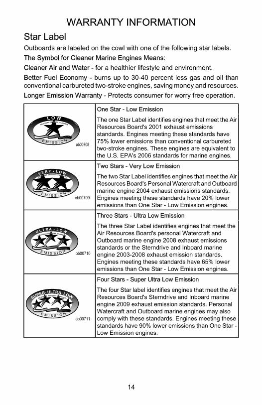
Star LabelOutboards are labeled on the cowl with one of the following star labels.The Symbol for Cleaner Marine Engines Means:Cleaner Air and Water ‑ for a healthier lifestyle and environment.Better Fuel Economy ‑ burns up to 30‑40 percent less gas and oil thanconventional carbureted two‑stroke engines, saving money and resources.Longer Emission Warranty ‑ Protects consumer for worry free operation.
ob00708
One Star ‑ Low Emission
The one Star Label identifies engines that meet the AirResources Board's 2001 exhaust emissionsstandards. Engines meeting these standards have75% lower emissions than conventional carburetedtwo‑stroke engines. These engines are equivalent tothe U.S. EPA's 2006 standards for marine engines.
FO IDA
ob00709
Two Stars ‑ Very Low Emission
The two Star Label identifies engines that meet the AirResources Board's Personal Watercraft and Outboardmarine engine 2004 exhaust emissions standards.Engines meeting these standards have 20% loweremissions than One Star ‑ Low Emission engines.
ASS
D
ob00710
Three Stars ‑ Ultra Low Emission
The three Star Label identifies engines that meet theAir Resources Board's personal Watercraft andOutboard marine engine 2008 exhaust emissionsstandards or the Sterndrive and Inboard marineengine 2003‑2008 exhaust emission standards.Engines meeting these standards have 65% loweremissions than One Star ‑ Low Emission engines.
RNF T
ob00711
Four Stars ‑ Super Ultra Low Emission
The four Star label identifies engines that meet the AirResources Board's Sterndrive and Inboard marineengine 2009 exhaust emission standards. PersonalWatercraft and Outboard marine engines may alsocomply with these standards. Engines meeting thesestandards have 90% lower emissions than One Star ‑Low Emission engines.
GENERAL INFORMATION
15
Boater's ResponsibilitiesThe operator (driver) is responsible for the correct and safe operation ofthe boat and safety of its occupants and general public. It is stronglyrecommended that each operator (driver) read and understand this entiremanual before operating the outboard.Be sure at least one additional person on board is instructed in the basicsof starting and operating the outboard and boat handling in case the driveris unable to operate the boat.
Before Operating Your OutboardRead this manual carefully. Learn how to operate your outboard properly.If you have any questions, contact your dealer.This manual as well as safety labels posted on the outboard use thefollowing safety alerts to draw your attention to special safety instructionsthat should be followed.
! WARNINGWARNING ‑ indicates a potentially hazardous situation that, if notavoided, could result in death or serious injury.
! CAUTIONCAUTION ‑ indicates a potentially hazardous situation that, if notavoided, may result in minor or moderate injury or property damage. Itmay also be used to alert against unsafe practices.
Boat Horsepower Capacity
! WARNINGUsing an outboard that exceeds the maximum horsepower limit of a boatcan: 1) cause loss of boat control 2) place too much weight at the transomaltering the designed flotation characteristics of the boat or 3) cause theboat to break apart particularly around the transom area. Overpoweringa boat can result in serious injury, death or boat damage.
GENERAL INFORMATION
16
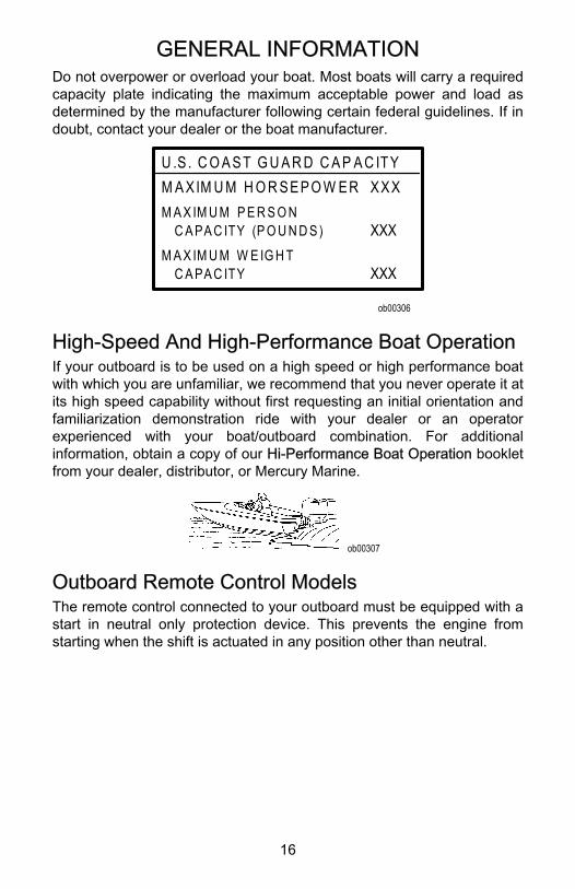
Do not overpower or overload your boat. Most boats will carry a requiredcapacity plate indicating the maximum acceptable power and load asdetermined by the manufacturer following certain federal guidelines. If indoubt, contact your dealer or the boat manufacturer.
U .S . C O A ST G U A R D C A P A C ITYM A XIM U M H O R SEPO W ER XXXM A X IM U M P E R S O N C A PA C ITY (P O U N D S ) XXXM A X IM U M W E IG H T C A PA C ITY XXX
ob00306
High‑Speed And High‑Performance Boat OperationIf your outboard is to be used on a high speed or high performance boatwith which you are unfamiliar, we recommend that you never operate it atits high speed capability without first requesting an initial orientation andfamiliarization demonstration ride with your dealer or an operatorexperienced with your boat/outboard combination. For additionalinformation, obtain a copy of our Hi‑Performance Boat Operation bookletfrom your dealer, distributor, or Mercury Marine.
ob00307
Outboard Remote Control ModelsThe remote control connected to your outboard must be equipped with astart in neutral only protection device. This prevents the engine fromstarting when the shift is actuated in any position other than neutral.
GENERAL INFORMATION
17
! WARNINGAvoid serious injury or death from a sudden unexpected accelerationwhen starting your engine. The design of this outboard requires that theremote control used with it must have a built in start in neutral onlyprotection device.
ob00308
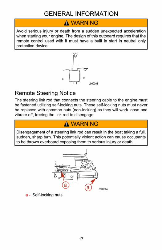
Remote Steering NoticeThe steering link rod that connects the steering cable to the engine mustbe fastened utilizing self‑locking nuts. These self‑locking nuts must neverbe replaced with common nuts (non‑locking) as they will work loose andvibrate off, freeing the link rod to disengage.
! WARNINGDisengagement of a steering link rod can result in the boat taking a full,sudden, sharp turn. This potentially violent action can cause occupantsto be thrown overboard exposing them to serious injury or death.
ob00655a a
a - Self‑locking nuts
GENERAL INFORMATION
18
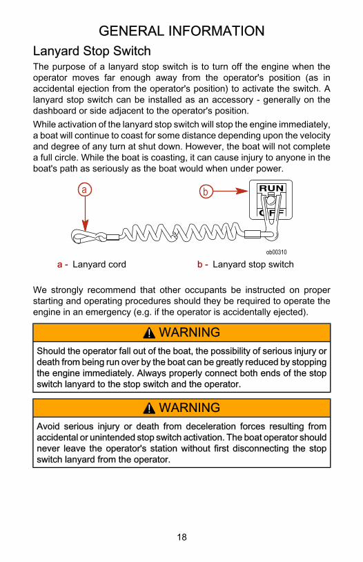
Lanyard Stop SwitchThe purpose of a lanyard stop switch is to turn off the engine when theoperator moves far enough away from the operator's position (as inaccidental ejection from the operator's position) to activate the switch. Alanyard stop switch can be installed as an accessory ‑ generally on thedashboard or side adjacent to the operator's position.While activation of the lanyard stop switch will stop the engine immediately,a boat will continue to coast for some distance depending upon the velocityand degree of any turn at shut down. However, the boat will not completea full circle. While the boat is coasting, it can cause injury to anyone in theboat's path as seriously as the boat would when under power.
ob00310
a b
a - Lanyard cord b - Lanyard stop switch
We strongly recommend that other occupants be instructed on properstarting and operating procedures should they be required to operate theengine in an emergency (e.g. if the operator is accidentally ejected).
! WARNINGShould the operator fall out of the boat, the possibility of serious injury ordeath from being run over by the boat can be greatly reduced by stoppingthe engine immediately. Always properly connect both ends of the stopswitch lanyard to the stop switch and the operator.
! WARNINGAvoid serious injury or death from deceleration forces resulting fromaccidental or unintended stop switch activation. The boat operator shouldnever leave the operator's station without first disconnecting the stopswitch lanyard from the operator.
GENERAL INFORMATION
19
Accidental or unintended activation of the switch during normal operationis also a possibility. This could cause any, or all, of the following potentiallyhazardous situations:• Occupants could be thrown forward due to unexpected loss of forward
motion ‑ a particular concern for passengers in the front of the boatwho could be ejected over the bow and possibly struck by the gearcase or propeller.
• Loss of power and directional control in heavy seas, strong current orhigh winds.
• Loss of control when docking.
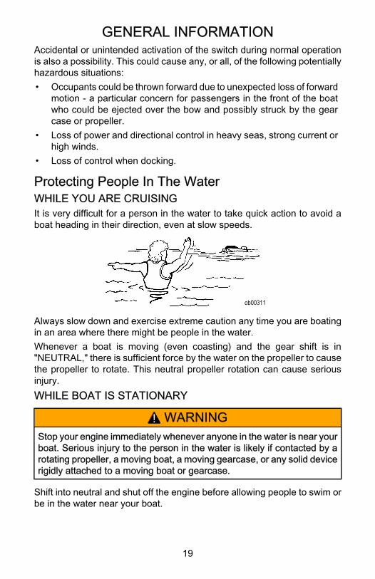
Protecting People In The WaterWHILE YOU ARE CRUISINGIt is very difficult for a person in the water to take quick action to avoid aboat heading in their direction, even at slow speeds.
ob00311
Always slow down and exercise extreme caution any time you are boatingin an area where there might be people in the water.Whenever a boat is moving (even coasting) and the gear shift is in"NEUTRAL," there is sufficient force by the water on the propeller to causethe propeller to rotate. This neutral propeller rotation can cause seriousinjury.WHILE BOAT IS STATIONARY
! WARNINGStop your engine immediately whenever anyone in the water is near yourboat. Serious injury to the person in the water is likely if contacted by arotating propeller, a moving boat, a moving gearcase, or any solid devicerigidly attached to a moving boat or gearcase.
Shift into neutral and shut off the engine before allowing people to swim orbe in the water near your boat.
GENERAL INFORMATION
20
Exhaust EmissionsBE ALERT TO CARBON MONOXIDE POISONINGCarbon monoxide is present in the exhaust fumes of all internal combustionengines. This includes the outboards, sterndrives and inboard engines thatpropel boats, as well as the generators that power various boataccessories. Carbon monoxide is a deadly gas that is odorless, colorlessand tasteless.Early symptoms of carbon monoxide poisoning which should not beconfused with seasickness or intoxication, include headache, dizziness,drowsiness, and nausea.
! WARNINGAvoid the combination of a running engine and poor ventilation.Prolonged exposure to carbon monoxide in sufficient concentration canlead to unconsciousness, brain damage, or death.
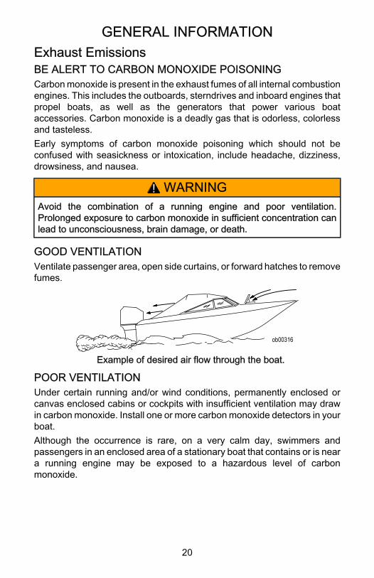
GOOD VENTILATIONVentilate passenger area, open side curtains, or forward hatches to removefumes.
ob00316
Example of desired air flow through the boat.
POOR VENTILATIONUnder certain running and/or wind conditions, permanently enclosed orcanvas enclosed cabins or cockpits with insufficient ventilation may drawin carbon monoxide. Install one or more carbon monoxide detectors in yourboat.Although the occurrence is rare, on a very calm day, swimmers andpassengers in an enclosed area of a stationary boat that contains or is neara running engine may be exposed to a hazardous level of carbonmonoxide.
GENERAL INFORMATION
21
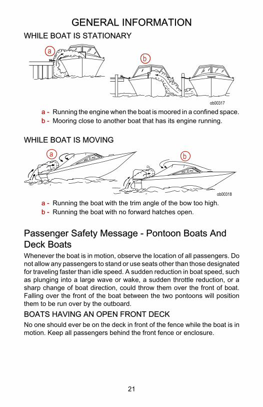
WHILE BOAT IS STATIONARY
ob00317
ab
a - Running the engine when the boat is moored in a confined space.b - Mooring close to another boat that has its engine running.
WHILE BOAT IS MOVING
ob00318
a b
a - Running the boat with the trim angle of the bow too high.b - Running the boat with no forward hatches open.
Passenger Safety Message ‑ Pontoon Boats AndDeck BoatsWhenever the boat is in motion, observe the location of all passengers. Donot allow any passengers to stand or use seats other than those designatedfor traveling faster than idle speed. A sudden reduction in boat speed, suchas plunging into a large wave or wake, a sudden throttle reduction, or asharp change of boat direction, could throw them over the front of boat.Falling over the front of the boat between the two pontoons will positionthem to be run over by the outboard.BOATS HAVING AN OPEN FRONT DECKNo one should ever be on the deck in front of the fence while the boat is inmotion. Keep all passengers behind the front fence or enclosure.
GENERAL INFORMATION
22
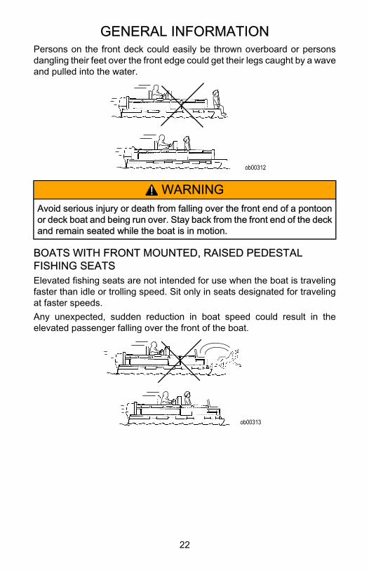
Persons on the front deck could easily be thrown overboard or personsdangling their feet over the front edge could get their legs caught by a waveand pulled into the water.
ob00312
! WARNINGAvoid serious injury or death from falling over the front end of a pontoonor deck boat and being run over. Stay back from the front end of the deckand remain seated while the boat is in motion.
BOATS WITH FRONT MOUNTED, RAISED PEDESTALFISHING SEATSElevated fishing seats are not intended for use when the boat is travelingfaster than idle or trolling speed. Sit only in seats designated for travelingat faster speeds.Any unexpected, sudden reduction in boat speed could result in theelevated passenger falling over the front of the boat.
ob00313
GENERAL INFORMATION
23
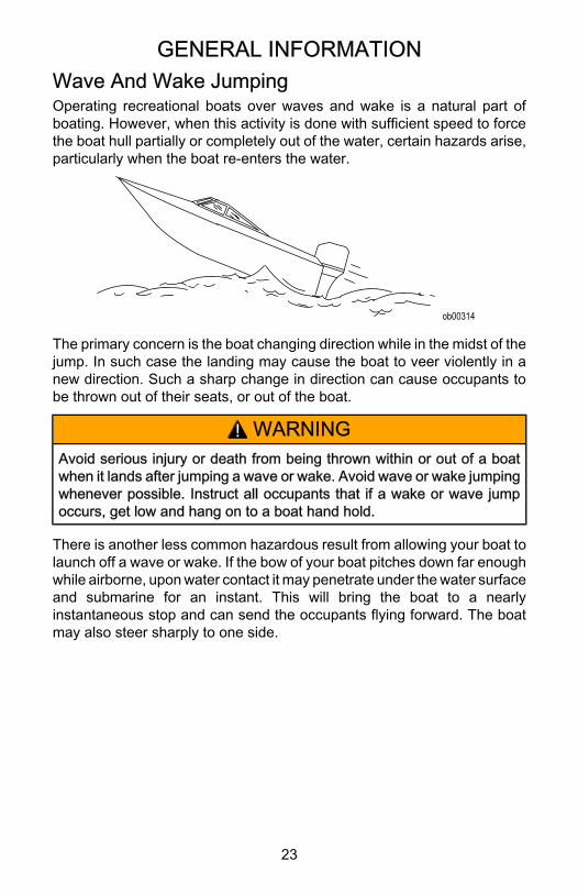
Wave And Wake JumpingOperating recreational boats over waves and wake is a natural part ofboating. However, when this activity is done with sufficient speed to forcethe boat hull partially or completely out of the water, certain hazards arise,particularly when the boat re‑enters the water.
ob00314
The primary concern is the boat changing direction while in the midst of thejump. In such case the landing may cause the boat to veer violently in anew direction. Such a sharp change in direction can cause occupants tobe thrown out of their seats, or out of the boat.
! WARNINGAvoid serious injury or death from being thrown within or out of a boatwhen it lands after jumping a wave or wake. Avoid wave or wake jumpingwhenever possible. Instruct all occupants that if a wake or wave jumpoccurs, get low and hang on to a boat hand hold.
There is another less common hazardous result from allowing your boat tolaunch off a wave or wake. If the bow of your boat pitches down far enoughwhile airborne, upon water contact it may penetrate under the water surfaceand submarine for an instant. This will bring the boat to a nearlyinstantaneous stop and can send the occupants flying forward. The boatmay also steer sharply to one side.
GENERAL INFORMATION
24
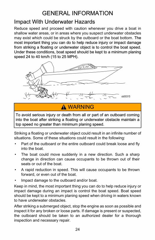
Impact With Underwater HazardsReduce speed and proceed with caution whenever you drive a boat inshallow water areas, or in areas where you suspect underwater obstaclesmay exist which could be struck by the outboard or the boat bottom. Themost important thing you can do to help reduce injury or impact damagefrom striking a floating or underwater object is to control the boat speed.Under these conditions, boat speed should be kept to a minimum planingspeed 24 to 40 km/h (15 to 25 MPH).
ob00315
! WARNINGTo avoid serious injury or death from all or part of an outboard cominginto the boat after striking a floating or underwater obstacle maintain atop speed no greater than minimum planing speed.
Striking a floating or underwater object could result in an infinite number ofsituations. Some of these situations could result in the following:• Part of the outboard or the entire outboard could break loose and fly
into the boat.• The boat could move suddenly in a new direction. Such a sharp
change in direction can cause occupants to be thrown out of theirseats or out of the boat.
• A rapid reduction in speed. This will cause occupants to be thrownforward, or even out of the boat.
• Impact damage to the outboard and/or boat.Keep in mind, the most important thing you can do to help reduce injury orimpact damage during an impact is control the boat speed. Boat speedshould be kept to a minimum planing speed when driving in waters knownto have underwater obstacles.After striking a submerged object, stop the engine as soon as possible andinspect it for any broken or loose parts. If damage is present or suspected,the outboard should be taken to an authorized dealer for a thoroughinspection and necessary repair.
GENERAL INFORMATION
25
The boat should also be checked for any hull fractures, transom fractures,or water leaks.Operating a damaged outboard could cause additional damage to otherparts of the outboard, or could affect control of the boat. If continued runningis necessary, do so at greatly reduced speeds.
! WARNINGAvoid serious injury or death from loss of boat control. Continued boatingwith major impact damage can result in sudden outboard componentfailure with or without subsequent impacts. Have the outboard thoroughlyinspected and any necessary repairs made.
Selecting Accessories For Your OutboardGenuine Mercury Precision or Quicksilver Accessories have beenspecifically designed and tested for your outboard. These accessories areavailable from Mercury Marine dealers.
! WARNINGCheck with your dealer before installation of accessories. The misuse ofacceptable accessories or the use of unacceptable accessories canresult in serious injury, death, or product failure.
Some accessories not manufactured or sold by Mercury Marine are notdesigned to be safely used with your outboard or outboard operatingsystem. Acquire and read the installation, operation, and maintenancemanuals for all your selected accessories.
Safe Boating SuggestionsIn order to safely enjoy the waterways, familiarize yourself with local andother governmental boating regulations and restrictions, and consider thefollowing suggestions.Use flotation devices. Have an approved personal flotation device ofsuitable size for each person aboard (it is the law) and have it readilyaccessible.Do not overload your boat. Most boats are rated and certified for maximumload (weight) capacities (refer to your boat capacity plate). If in doubt,contact your dealer or the boats manufacturer.Perform safety checks and required maintenance. Follow a regularschedule and ensure that all repairs are properly made.
GENERAL INFORMATION
26
Know and obey all nautical rules and laws of the waterways. Boat operatorsshould complete a boating safety course. Courses are offered in the U.S.A.by 1) The U.S. Coast Guard Auxiliary, 2) The Power Squadron, 3) The RedCross and 4) your state boating law enforcement agency. Inquiries may bemade to the Boating Hotline, 1‑800‑368‑5647 or the Boat U.S. Foundationinformation number 1‑800‑336‑BOAT.Make sure everyone in the boat is properly seated. Do not allow anyone tosit or ride on any part of the boat that was not intended for such use. Thisincludes the back of seats, gunwales, transom, bow, decks, raised fishingseats, any rotating fishing seat; or anywhere that an unexpectedacceleration, sudden stopping, unexpected loss of boat control, or suddenboat movement could cause a person to be thrown overboard or into theboat.Never be under the influence of alcohol or drugs while boating (it is thelaw). Alcohol or drug use impairs your judgment and greatly reduces yourability to react quickly.Prepare other boat operators. Instruct at least one other person on boardin the basics of starting and operating the outboard, and boat handling, incase the driver becomes disabled or falls overboard.Passenger boarding. Stop the engine whenever passengers are boarding,unloading, or are near the back (stern) of the boat. Just shifting theoutboard into neutral is not sufficient.Be alert. The operator of the boat is responsible by law to maintain a properlookout by sight and hearing. The operator must have an unobstructed viewparticularly to the front. No passengers, load, or fishing seats should blockthe operators view when operating the boat above idle speed.Never drive your boat directly behind a water skier in case the skier falls.As an example, your boat traveling at 40 km/h (25 MPH) will overtake afallen skier 61 m (200 ft.) in front of you in 5 seconds.Watch fallen skiers. When using your boat for water skiing or similaractivities, always keep a fallen or down skier on the operator's side of theboat while returning to assist the skier. The operator should always havethe down skier in sight and never back up to the skier or anyone in thewater.
GENERAL INFORMATION
27
Report accidents. Boat operators are required by law to file a BoatingAccident Report with their state boating law enforcement agency whentheir boat is involved in certain boating accidents. A boating accident mustbe reported if 1) there is loss of life or probable loss of life, 2) there ispersonal injury requiring medical treatment beyond first aid, 3) there isdamage to boats or other property where the damage value exceeds$500.00 or 4) there is complete loss of the boat. Seek further assistancefrom local law enforcement.
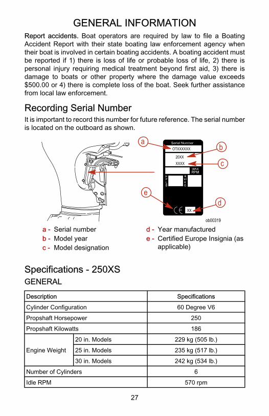
Recording Serial NumberIt is important to record this number for future reference. The serial numberis located on the outboard as shown.
20XX
XX
OTXXXXXX
XXXX
b
e
a
d
ob00319
c
a - Serial numberb - Model yearc - Model designation
d - Year manufacturede - Certified Europe Insignia (as
applicable)
Specifications ‑ 250XSGENERAL
Description Specifications
Cylinder Configuration 60 Degree V6
Propshaft Horsepower 250
Propshaft Kilowatts 186
Engine Weight
20 in. Models 229 kg (505 lb.)
25 in. Models 235 kg (517 lb.)
30 in. Models 242 kg (534 lb.)
Number of Cylinders 6
Idle RPM 570 rpm
GENERAL INFORMATION
28
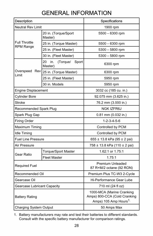
Description Specifications
Neutral Rev Limit 1900 rpm
Full ThrottleRPM Range
20 in. (Torque/SportMaster)
5500 – 6300 rpm
25 in. (Torque Master) 5500 – 6300 rpm
25 in. (Fleet Master) 5300 – 5800 rpm
30 in. (Fleet Master) 5300 – 5800 rpm
Overspeed RevLimit
20 in. (Torque/ SportMaster) 6300 rpm
25 in. (Torque Master) 6300 rpm
25 in. (Fleet Master) 5950 rpm
30 in. Models 5950 rpm
Engine Displacement 3032 cc (185 cu. in.)
Cylinder Bore 92.075 mm (3.625 in.)
Stroke 76.2 mm (3.000 in.)
Recommended Spark Plug NGK IZFR6J
Spark Plug Gap 0.81 mm (0.032 in.)
Firing Order 1‑2‑3‑4‑5‑6
Maximum Timing Controlled by PCM
Idle Timing Controlled by PCM
Fuel Line Pressure 655 ± 13.8 kPa (95 ± 2 psi)
Air Pressure 758 ± 13.8 kPa (110 ± 2 psi)
Gear RatioTorque/Sport Master 1.62:1 or 1.75:1
Fleet Master 1.75:1
Required Fuel Premium Unleaded87 R+M/2 octane (92 RON)
Recommended Oil Premium Plus TC‑W3 2‑Cycle
Gearcase Oil Hi‑Performance Gear Lube
Gearcase Lubricant Capacity 710 ml (24 fl oz)
Battery Rating1000‑MCA (Marine Cranking
Amps) 800‑CCA (Cold CrankingAmps) 105 Amp Hours1.
Charging System Output 50 Amps Max
1. Battery manufacturers may rate and test their batteries to different standards.Consult with the specific battery manufacturer for comparison ratings.
GENERAL INFORMATION
29
NOTE: Where applicable, specifications are derived at sea level.
Special Tools and KitsDescription Part Number
Stainless Steel Tilt Pin (Three‑Ram Trim Systems) 17‑49930A1
Oil Syringe 91‑803976T
Flushing Attachment (for Torque/Fleet Master gearcase) 44357T2
Flushing Attachment (for Sport Master gearcase) 848998A1
Dual Water Pick‑Up Flush Seal Kit (Fleet/Torque Master gearcase) 881150K1
GENERAL INFORMATION
30
Component Identification
250xs
1 2
3
4
5
6
7
8
9
10
1112
13
3540
1 - Top cowl2 - Side cowl latches (both
sides)3 - Front cowl latch4 - Auxiliary tilt switch5 - Clamp/Swivel bracket6 - Gearcase7 - Cooling water intake
(location dependent ongearcase)
8 - Skeg9 - Anode plate10 - Anti‑ventilation plate11 - Drive shaft housing12 - Water pump indicator13 - Bottom cowl
GENERAL INFORMATION
31
Propeller SelectionPropping the engine at the higher end of the RPM range may increaseacceleration, but decrease top boat speed. Conversely, propping theengine at the lower end of the range may increase top boat speed buthinder acceleration. Mercury Marine recommends selecting a propeller thatallows the engine to operate in the upper half of the recommended fullthrottle RPM range with the boat normally loaded (refer to GeneralInformation ‑ Specifications). This RPM range allows for better accelerationwhile maintaining maximum boat speed.All "L" models (20 in.) and some "XL" models (25 in.) are capable ofoperating at engine speeds of up to 6300 RPM. This increased enginespeed gives the operator a greater range of pitch selection. However,propping at the uppermost limit of the RPM range may not necessarilyresult in improved high speed performance. Boat weight and hull designinfluence the effectiveness of this increased engine speed and maydecrease top boat speed.If full throttle operation is below the recommended full throttle range, thepropeller must be changed to prevent loss of performance and possibleengine damage. On the other hand, operating an engine above therecommended operating RPM range will cause higher than normal wearor damage. Generally, there is a 200‑300 RPM change between propellerpitches.
ob00323
If changing conditions cause the RPM to drop below the recommendedrange (such as warmer, more humid weather, operation at higherelevations, increased boat load, or a dirty boat bottom/gearcase), apropeller change or cleaning may be required to maintain performance andensure the outboards durability.Check full‑throttle RPM, using an accurate tachometer, with the enginetrimmed out to a balanced‑steering condition (steering effort equal in bothdirections) without causing the propeller to break loose.
TRANSPORTING
32
Trailering Boat/OutboardTrailer your boat with the outboard tilted down in a vertical operatingposition.If additional ground clearance is required, the outboard should be tilted upusing an accessory outboard support device. Refer to your local dealer forrecommendations. Additional clearance may be required for railroadcrossings, driveways and trailer bouncing.
or26
IMPORTANT: Do not rely on the power trim/tilt system or tilt support leverto maintain proper ground clearance for trailering. The outboard tilt supportlever is not intended to support the outboard for trailering.Shift the outboard to forward gear. This prevents the propeller fromspinning freely.
FUEL AND OIL
33
Avoiding Fuel Flow Restrictions
! CAUTIONAvoid engine damage. Adding components to the fuel supply system,such as filters, valves, fittings, etc., may restrict the fuel flow. Thiscondition may cause the engine to stall at low speeds and create leanfuel conditions at high speeds, causing engine damage.
Fuel RequirementsUse a major brand of unleaded gasoline, preferably without alcohol.
! CAUTIONUse of improper fuel can seriously damage your engine. Engine damageresulting from use of improper fuel is considered misuse of the engineand damage caused thereby will not be covered under the MercuryRacing limited warranty.
OCTANE REQUIREMENTS (U.S./CANADA)
FUEL TYPE MINIMUM POSTED OCTANE
Unleaded1. 87 (R+M)/2
OCTANE REQUIREMENTS (OUTSIDE THE U.S./CANADA)
FUEL TYPE MINIMUM POSTED OCTANE
Unleaded 2. 92 RON
USING REFORMULATED (OXYGENATED) FUELS (USAONLY)This type of fuel is required in certain areas of the U.S. The two types ofoxygenates used in these fuels are alcohol (Ethanol) or Ether (MTBE orETBE). If Ethanol is the oxygenate that is used in the gasoline in your area,refer to the Fuel Containing Alcohol section.These reformulated fuels are acceptable for use in your Mercury engine.1. Mercury Racing does not recommend using leaded gasoline. Read the
information in the Fuel Containing Alcohol section.2. Mercury Racing does not recommend using leaded gasoline. Leaded gasoline
is acceptable in areas where unleaded gasoline is not available; however,exhaust passageway corrosion may occur due to the accumulation of exhaustedlead particles. Automotive fuels that contain fuel injector cleaner arerecommended for added internal cleanliness.
FUEL AND OIL
34
FUEL CONTAINING ALCOHOLIf the fuel in your area contains either methanol (methyl alcohol) or ethanol(ethyl alcohol), you should be aware of certain adverse effects that canoccur. These adverse effects are more severe with methanol. Increasingthe percentage of alcohol in the fuel can also worsen these adverse effects.Some of these adverse effects are caused because the alcohol in the fuelcan absorb moisture from the air, resulting in a separation of the water/alcohol from the gasoline in the fuel tank.The fuel system components on your Mercury engine will withstand up to10% alcohol content in the gasoline. We do not know what percentage yourboat’s fuel system will withstand. Contact your boat manufacturer forspecific recommendations on the boats fuel system components (fueltanks, fuel lines, and fittings).Fuel containing alcohol may increase:• Corrosion of metal parts.• Deterioration of rubber or plastic parts.• Fuel permeation through rubber fuel lines.• Starting and operating difficulties.
! CAUTIONWhen operating a Mercury engine with fuel containing alcohol, avoidstoring the fuel in the fuel tank for long periods of time. Long storageperiods, common to boats, create unique problems. In cars,alcohol‑blend fuels are normally consumed before they can absorbenough moisture to cause trouble. However, boats often sit idle longenough for phase separation to take place. In addition, internal corrosionmay take place during storage if alcohol has washed protective oil filmsfrom internal components.
IMPORTANT: Because of possible adverse effects of alcohol in gasoline,it is recommended that only alcohol‑free fuel be used where possible.If only fuel containing alcohol is available, or if the presence of alcohol isunknown, increased inspection frequency for leaks and abnormalities isrequired.
Oil RecommendationRecommended Oil Premium Plus 2‑Cycle TC‑W3 Outboard Oil
FUEL AND OIL
35
TC‑W3 Premium Plus Outboard Oil is a higher grade oil that providesincreased lubrication and extra resistance to carbon buildup when usedwith good or varying grades of gasoline.IMPORTANT: Oil must be NMMA certified TC‑W3 2‑Cycle oil.Periodically consult with your dealer to get the latest gasoline and oilrecommendations. If Quicksilver 2‑Cycle Outboard Oil is not available,substitute another brand of 2‑Cycle outboard oil that is NMMA CertifiedTC‑W3. The use of an inferior 2‑Cycle outboard oil can reduce enginedurability. Damage from use of inferior oil may not be covered under thelimited warranty.
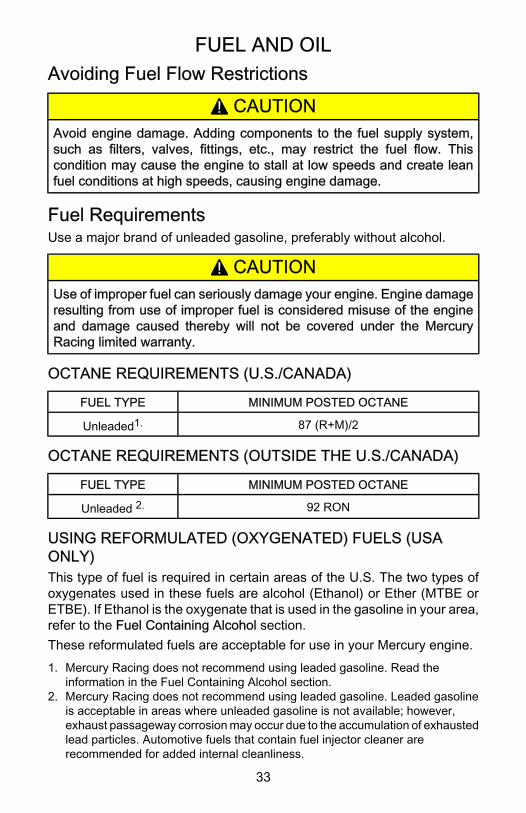
Filling Remote Oil TankRemove filler cap and fill with the specified oil. Oil tank capacity is11.5 liters (3 gallons). Replace filler cap and tighten securely.IMPORTANT: Always make sure the oil tank caps are threaded on tight.An air leak will prevent oil flow to the engine.
or27
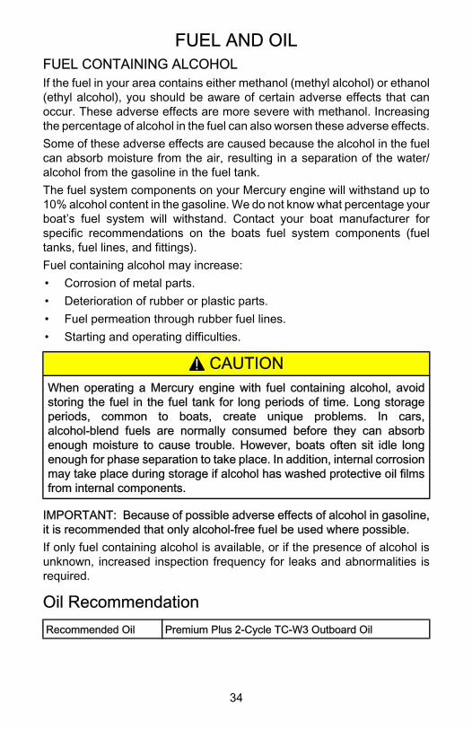
Filling Engine Mounted Oil Reservoir TankRemove the top cowl. Loosen the fill cap on the engine oil reservoir tank.Run the engine until all the air has been vented out of the oil reservoir tankand tank is filled with oil to the point of overflow. Re‑tighten the fill cap. Stopthe engine and replace the top cowl.
or28
FUEL AND OIL
36
NOTE: Filling this tank is only necessary if the oil level should ever dropand the low oil warning system is activated.
Filling Fuel Tank• Fill fuel tanks outdoors away from heat, sparks, and open flames.• Remove portable fuel tanks from boat to refill them.• Always stop engine before refilling tanks.• Do not completely fill the fuel tanks. Leave approximately 10% of the
tank volume unfilled. Fuel will expand in volume as its temperaturerises and can leak under pressure if the tank is completely filled.
! WARNINGAvoid serious injury or death from a gasoline fire or explosion. Alwaysstop the engine and do not smoke or allow open flames or sparks in thearea while filling fuel tanks.
FEATURES AND CONTROLS
37
Remote Control FeaturesYour boat may be equipped with one of the Mercury Precision orQuicksilver remote controls shown. If not, consult your dealer for adescription of the functions and operations of the remote control.
ee
aa
dd dd
eeffgg
aa
bbff
cc
gghh
bbcc
aa
ff
ii
cc
ii
ob00329
a - Control handle ‑ forward, neutral, reverse.b - Neutral release leverc - Trim/tilt switch (if equipped). ‑ Refer to Features & Controls ‑
Power Trim and Tilt.d - Lanyard stop switch ‑ Refer to General Information ‑ Lanyard
Stop Switch.e - Lanyard ‑ Refer to General Information ‑ Lanyard Stop Switch.f - Throttle friction adjustment ‑ Console controls require cover
removal for adjustment.g - Ignition key switch ‑ "OFF," "ON," START."h - Fast idle lever ‑ Refer to Operation ‑ Starting the Engine.i - Throttle only button ‑ Refer to Operation ‑ Starting the Engine.
FEATURES AND CONTROLS
38
Zero Effort Control Featuresa
b
c
4090
a - Throttle leverb - Trim switchc - Shift lever
Warning SystemThe warning system incorporates a warning horn inside the boat. Thewarning horn may be located inside the remote control or under the dashconnected to the ignition key switch.
a
b
ob00662
a - Inside the remote controlb - Under the dashboard
WARNING HORN SIGNALSWhen the key switch is turned to the "ON" position, the horn will turn on fora moment as a test to tell you the horn is working.
FEATURES AND CONTROLS
39
The warning horn will emit either a continuous beep or intermittent shortbeeps. This will alert the operator and help identify the following listedsituations. Refer to the Troubleshooting section for specific information. Forvisual display of the specific engine functions and for additional enginedata, refer to SmartCraft product information.ENGINE GUARDIAN SYSTEMThe Engine Guardian System monitors the critical sensors on the enginefor any early indications of problems. The system will respond to a problemby emitting a continuous beep and/or reducing engine power in order toprovide engine protection.If Guardian System is activated, the system must be reset before theengine will operate at higher speeds. Moving throttle lever back to idleposition resets the system.
Problem Horn MonitorDisplay
GuardianActivated
Percentage ofFull Engine
PowerAvailable
Power Up/System Check Single Beep Yes N/A N/A
During EngineBreak‑In No No No 100%
Low Oil inEngine Oil Tank
4 Beeps... 2 MinutesOff Yes Yes 95%
Critically LowOil in Engine Oil
TankContinuous Beep Yes Yes 5%
Oil PumpElectricalFailure
Continuous Beep Yes Yes 5%
ThrottlePosition Sensor
Failure
ContinuousIntermittent Beeping Yes Yes 95%
Overspeed Continuous Beep Yes Yes 65%
High EngineTemperature Continuous Beep Yes Yes From 100%
down to 4%
Low BlockWater Pressure Continuous Beep Yes Yes From 100%
down to 4%
Faulty Sensor(Block psi,
Coolant Temp)No Yes Yes 95%
FEATURES AND CONTROLS
40
Problem Horn MonitorDisplay
GuardianActivated
Percentage ofFull Engine
PowerAvailable
Battery VoltageOut of Limits
SingleBeep...Continuous
Beep when GuardianEngages
Yes Yes
<10 v = 0%
<11.5 v = 50%
11.5 ‑ 16 v =100%
>16 v = 50 %
>17 v = 0%
Horn Failure No Yes Yes 95%
Water In Fuel 4 Beeps... 2 MinutesOff Yes No N/A
MAP SensorFailure No Yes Yes 95%
AirTemperature
Sensor FailureNo Yes No N/A
Ignition CoilFailure No Yes No N/A
Injector Failure No Yes No N/A
SMARTCRAFT PRODUCTA Mercury SmartCraft System instrument package can be purchased forthis power package. A few functions some of the instrument packages willdisplay are engine RPM, coolant temp, water pressure, battery voltage,fuel consumption and engine operating hours.The SmartCraft Instrument package will also aid in Engine Guardiandiagnostics. The SmartCraft Instrument package will display critical enginealarm data and potential problems.Refer to the Mercury SmartCraft Operator’s Supplement provided with thepower package for the warning functions monitored on your power packageand basic operation of the SmartCraft Instrument package.
Overspeed Rev LimitThe PCM does not allow the engine to exceed the rev limit. Refer toSpecifications to determine this engine’s RPM limit.
FEATURES AND CONTROLS
41
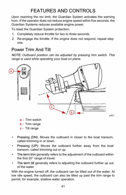
Upon reaching the rev limit, the Guardian System activates the warninghorn. If the operator does not reduce engine speed within five seconds, theGuardian Systems reduces available engine power.To reset the Guardian System protection:1. Completely reduce throttle for two to three seconds.2. Re‑engage the throttle. If the engine does not respond, repeat step
one.
Power Trim And TiltNOTE: Outboard position can be adjusted by pressing trim switch. Thisrange is used while operating your boat on plane.
a
cb
or30-1
a - Trim switchb - Trim rangec - Tilt range
• Pressing (DN): Moves the outboard in closer to the boat transom,called trimming in or down.
• Pressing (UP): Moves the outboard further away from the boattransom, called trimming out or up.
• The term trim generally refers to the adjustment of the outboard withinthe first 20° range of travel.
• The term tilt generally refers to adjusting the outboard further up outof the water.
With the engine turned off, the outboard can be tilted out of the water. Atlow idle speed, the outboard can also be tilted up past the trim range topermit, for example, shallow water operation.
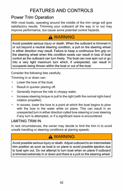
FEATURES AND CONTROLS
42
Power Trim OperationWith most boats, operating around the middle of the trim range will givesatisfactory results. Trimming your outboard all the way in or out mayimprove performance, but cause some potential control hazards.
! WARNINGAvoid possible serious injury or death. When the outboard is trimmed inor out beyond a neutral steering condition, a pull on the steering wheelin either direction may result. Failure to keep a continuous firm grip onthe steering wheel when this condition exists can result in loss of boatcontrol as the outboard can turn freely. The boat can now spin out or gointo a very tight maximum turn which, if unexpected, can result inoccupants being thrown within the boat or out of the boat.
Consider the following lists carefully.Trimming in or down can:• Lower the bow of the boat.• Result in quicker planing off.• Generally improve the ride in choppy water.• Increase steering torque or pull to the right (with the normal right‑hand
rotation propeller).• In excess, lower the bow to a point at which the boat begins to plow
with the bow in the water while on plane. This can result in anunexpected turn in either direction called bow steering or over steeringif any turn is attempted, or if a significant wave is encountered.
LIMITING TRIM INIn rare circumstances, the owner may decide to limit the trim in to avoidunsafe handling or steering conditions at planing speeds.
! WARNINGAvoid possible serious injury or death. Adjust outboard to an intermediatetrim position as soon as boat is on plane to avoid possible ejection dueto boat spin out. Do not attempt to turn boat when on plane if outboardis trimmed extremely in or down and there is a pull on the steering wheel.
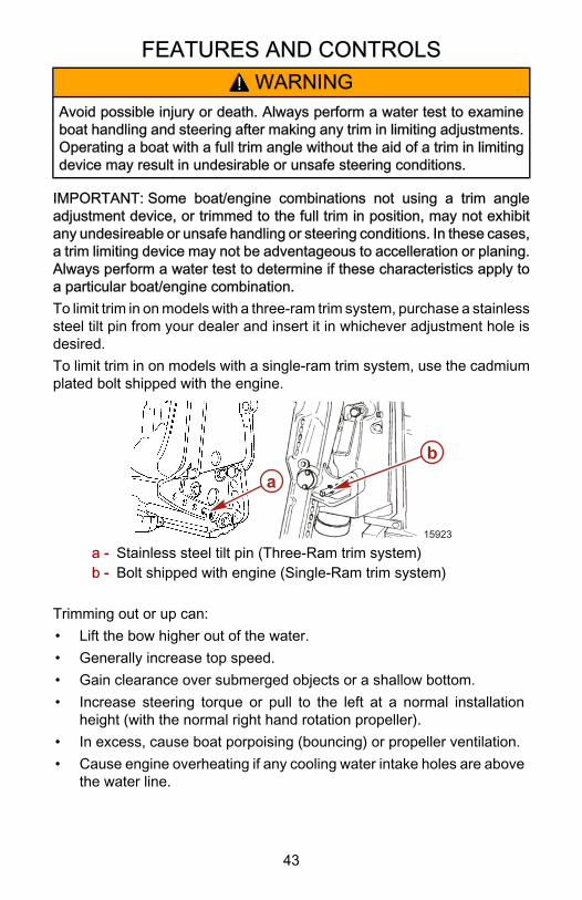
FEATURES AND CONTROLS
43
! WARNINGAvoid possible injury or death. Always perform a water test to examineboat handling and steering after making any trim in limiting adjustments.Operating a boat with a full trim angle without the aid of a trim in limitingdevice may result in undesirable or unsafe steering conditions.
IMPORTANT: Some boat/engine combinations not using a trim angleadjustment device, or trimmed to the full trim in position, may not exhibitany undesireable or unsafe handling or steering conditions. In these cases,a trim limiting device may not be adventageous to accelleration or planing.Always perform a water test to determine if these characteristics apply toa particular boat/engine combination.To limit trim in on models with a three‑ram trim system, purchase a stainlesssteel tilt pin from your dealer and insert it in whichever adjustment hole isdesired.To limit trim in on models with a single‑ram trim system, use the cadmiumplated bolt shipped with the engine.
15923
ab
a - Stainless steel tilt pin (Three‑Ram trim system)b - Bolt shipped with engine (Single‑Ram trim system)
Trimming out or up can:• Lift the bow higher out of the water.• Generally increase top speed.• Gain clearance over submerged objects or a shallow bottom.• Increase steering torque or pull to the left at a normal installation
height (with the normal right hand rotation propeller).• In excess, cause boat porpoising (bouncing) or propeller ventilation.• Cause engine overheating if any cooling water intake holes are above
the water line.
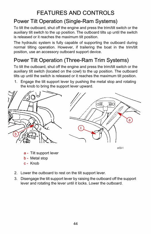
FEATURES AND CONTROLS
44
Power Tilt Operation (Single‑Ram Systems)To tilt the outboard, shut off the engine and press the trim/tilt switch or theauxiliary tilt switch to the up position. The outboard tilts up until the switchis released or it reaches the maximum tilt position.The hydraulic system is fully capable of supporting the outboard duringnormal tilting operation. However, if trailering the boat in the trim/tiltposition, use an accessory outboard support device.
Power Tilt Operation (Three‑Ram Trim Systems)To tilt the outboard, shut off the engine and press the trim/tilt switch or theauxiliary tilt switch (located on the cowl) to the up position. The outboardtilts up until the switch is released or it reaches the maximum tilt position.1. Engage the tilt support lever by pushing the metal stop and rotating
the knob to bring the support lever upward.
bc
a
or33-1
a - Tilt support leverb - Metal stopc - Knob
2. Lower the outboard to rest on the tilt support lever.3. Disengage the tilt support lever by raising the outboard off the support
lever and rotating the lever until it locks. Lower the outboard.
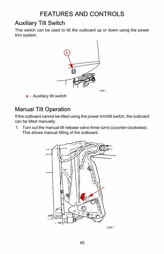
FEATURES AND CONTROLS
45
Auxiliary Tilt SwitchThis switch can be used to tilt the outboard up or down using the powertrim system.
or54-1
a
a - Auxiliary tilt switch
Manual Tilt OperationIf the outboard cannot be tilted using the power trim/tilt switch, the outboardcan be tilted manually.1. Turn out the manual tilt release valve three turns (counter‑clockwise).
This allows manual tilting of the outboard.
or34-1
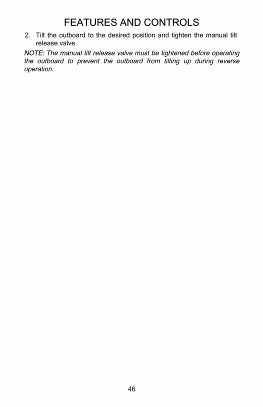
FEATURES AND CONTROLS
46
2. Tilt the outboard to the desired position and tighten the manual tiltrelease valve.
NOTE: The manual tilt release valve must be tightened before operatingthe outboard to prevent the outboard from tilting up during reverseoperation.
OPERATION
47
Engine Break‑in
! CAUTIONSevere damage to the engine can result by not complying with the enginebreak‑in proceedure. Engine damage may not be covered by the limitedwarranty.
! WARNINGAvoid loss of boat control or an unsafe boat handling situation. Increasingtrim under can place greater load on an engine and enhance breakin. Athigher speeds, increasing trim under could produce a dangerous boathandling situation. It is the boat operator’s responsibility to always drivein a safe manner.
Break‑in Procedure
Always vary throttle settings during Break‑in
1st Hour
• Allow engine to warm‑up for 30 ‑ 60 seconds.
• Do not idle for more than 5 minutes
• Run the engine the majority of the time between 4000 ‑ 5400 RPM(approximately three quarter throttle).
• Change engine speed approximately every two (2) minutes.
• Avoid trimming the outboard out (up) beyond a vertical trim position duringoperation.
• Avoid using hydraulic jack plate (if equipped) to raise engine during break‑incycle.
Next 3 Hours: Change engine speed every 10 minutes.
Engine Break‑in Fuel Mixture
! CAUTIONAvoid engine damage. Do not add oil to the gasoline in the fuel tank.
The Propulsion Control Module (PCM) controls oil and fuel mixture duringengine break‑in.
Pre‑Starting Check ListEngine lowered to run position with all water intake holes submerged
OPERATION
48
Fuel tank vent cap open or fuel drain valve on.
Fuel supply OK
Lanyard stop switch in "RUN" position and cord connected.
Remote control in neutral
Top cowl latches secure.
Make inspection checks listed in the Inspection and MaintenanceSchedule. Refer to Maintenance section.
Operating In Freezing TemperaturesWhen using your outboard or having your outboard moored in freezing ornear freezing temperatures, keep the outboard tilted down at all times sothe gearcase is submerged. This prevents trapped water in gearcase fromfreezing and causing possible damage to the water pump and othercomponents.If there is a chance of ice forming on the water, the outboard should beremoved and drained completely of water. If ice should form at the waterlevel inside the outboard driveshaft housing, it will block water flow to theengine causing possible damage.
Operating In Salt Water Or Polluted WaterWe recommend that you flush the internal water passages of your outboardwith fresh water after each use in salt or polluted water. This will prevent abuildup of deposits from clogging the water passages. Refer toMaintenance ‑ Flushing The Cooling System.If you keep your boat moored in the water, always tilt the outboard so thegearcase is completely out of water (except in freezing temperatures) whennot in use.Wash the outboard exterior and flush out the exhaust outlet of the propellerand gearcase with fresh water after each use. Each month, spray MercuryPrecision or Quicksilver Corrosion Guard on external metal surfaces. Donot spray on corrosion control anodes as this will reduce the effectivenessof the anodes.
Operating at High ElevationsYour engine automatically compensates for high elevation changes. Adifferent pitch propeller may help reduce some normal performance lossresulting from reduced oxygen in the air. Consult your dealer.
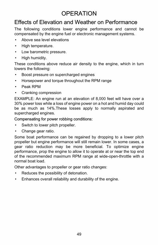
OPERATION
49
Effects of Elevation and Weather on PerformanceThe following conditions lower engine performance and cannot becompensated by the engine fuel or electronic management systems.• Above sea level elevations• High temperature.• Low barometric pressure.• High humidity.These conditions above reduce air density to the engine, which in turnlowers the following:• Boost pressure on supercharged engines• Horsepower and torque throughout the RPM range• Peak RPM• Cranking compressionEXAMPLE: An engine run at an elevation of 8,000 feet will have over a30% power loss while a loss of engine power on a hot and humid day couldbe as much as 14%.These losses apply to normally aspirated andsupercharged engines.Compensating for power robbing conditions:• Switch to lower pitch propeller.• Change gear ratio.Some boat performance can be regained by dropping to a lower pitchpropeller but engine performance will still remain lower. In some cases, agear ratio reduction may be more beneficial. To optimize engineperformance, prop the engine to allow it to operate at or near the top endof the recommended maximum RPM range at wide‑open‑throttle with anormal boat load.Other advantages to propeller or gear ratio changes:• Reduces the possibility of detonation.• Enhances overall reliability and durability of the engine.
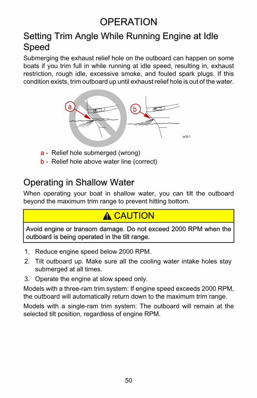
OPERATION
50
Setting Trim Angle While Running Engine at IdleSpeedSubmerging the exhaust relief hole on the outboard can happen on someboats if you trim full in while running at idle speed, resulting in, exhaustrestriction, rough idle, excessive smoke, and fouled spark plugs. If thiscondition exists, trim outboard up until exhaust relief hole is out of the water.
or35-1
a b
a - Relief hole submerged (wrong)b - Relief hole above water line (correct)
Operating in Shallow WaterWhen operating your boat in shallow water, you can tilt the outboardbeyond the maximum trim range to prevent hitting bottom.
! CAUTIONAvoid engine or transom damage. Do not exceed 2000 RPM when theoutboard is being operated in the tilt range.
1. Reduce engine speed below 2000 RPM.2. Tilt outboard up. Make sure all the cooling water intake holes stay
submerged at all times.3. Operate the engine at slow speed only.Models with a three‑ram trim system: If engine speed exceeds 2000 RPM,the outboard will automatically return down to the maximum trim range.Models with a single‑ram trim system: The outboard will remain at theselected tilt position, regardless of engine RPM.
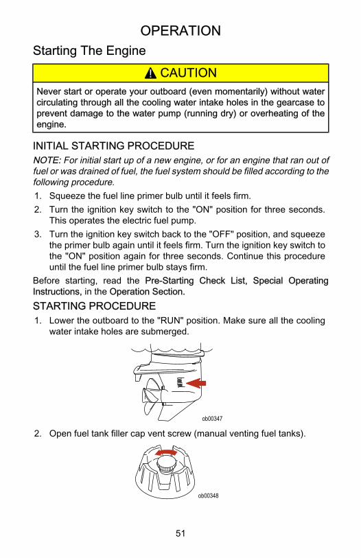
OPERATION
51
Starting The Engine
! CAUTIONNever start or operate your outboard (even momentarily) without watercirculating through all the cooling water intake holes in the gearcase toprevent damage to the water pump (running dry) or overheating of theengine.
INITIAL STARTING PROCEDURENOTE: For initial start up of a new engine, or for an engine that ran out offuel or was drained of fuel, the fuel system should be filled according to thefollowing procedure.1. Squeeze the fuel line primer bulb until it feels firm.2. Turn the ignition key switch to the "ON" position for three seconds.
This operates the electric fuel pump.3. Turn the ignition key switch back to the "OFF" position, and squeeze
the primer bulb again until it feels firm. Turn the ignition key switch tothe "ON" position again for three seconds. Continue this procedureuntil the fuel line primer bulb stays firm.
Before starting, read the Pre‑Starting Check List, Special OperatingInstructions, in the Operation Section.STARTING PROCEDURE1. Lower the outboard to the "RUN" position. Make sure all the cooling
water intake holes are submerged.
ob00347
2. Open fuel tank filler cap vent screw (manual venting fuel tanks).
ob00348
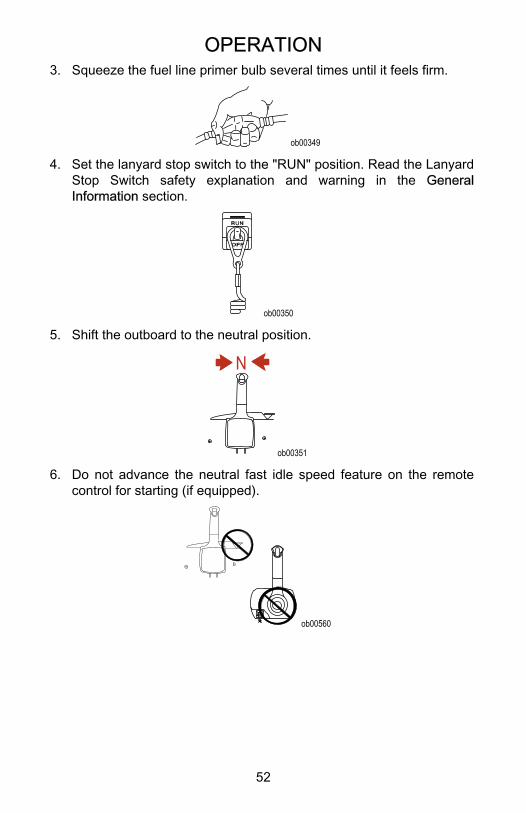
OPERATION
52
3. Squeeze the fuel line primer bulb several times until it feels firm.
ob00349
4. Set the lanyard stop switch to the "RUN" position. Read the LanyardStop Switch safety explanation and warning in the GeneralInformation section.
ob00350
5. Shift the outboard to the neutral position.
N
ob00351
6. Do not advance the neutral fast idle speed feature on the remotecontrol for starting (if equipped).
ob00560
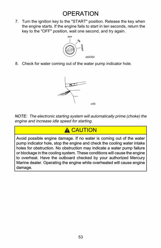
OPERATION
53
7. Turn the ignition key to the "START" position. Release the key whenthe engine starts. If the engine fails to start in ten seconds, return thekey to the "OFF" position, wait one second, and try again.
ob00354
8. Check for water coming out of the water pump indicator hole.
or55
NOTE: The electronic starting system will automatically prime (choke) theengine and increase idle speed for starting.
! CAUTIONAvoid possible engine damage. If no water is coming out of the waterpump indicator hole, stop the engine and check the cooling water intakeholes for obstruction. No obstruction may indicate a water pump failureor blockage in the cooling system. These conditions will cause the engineto overheat. Have the outboard checked by your authorized MercuryMarine dealer. Operating the engine while overheated will cause enginedamage.
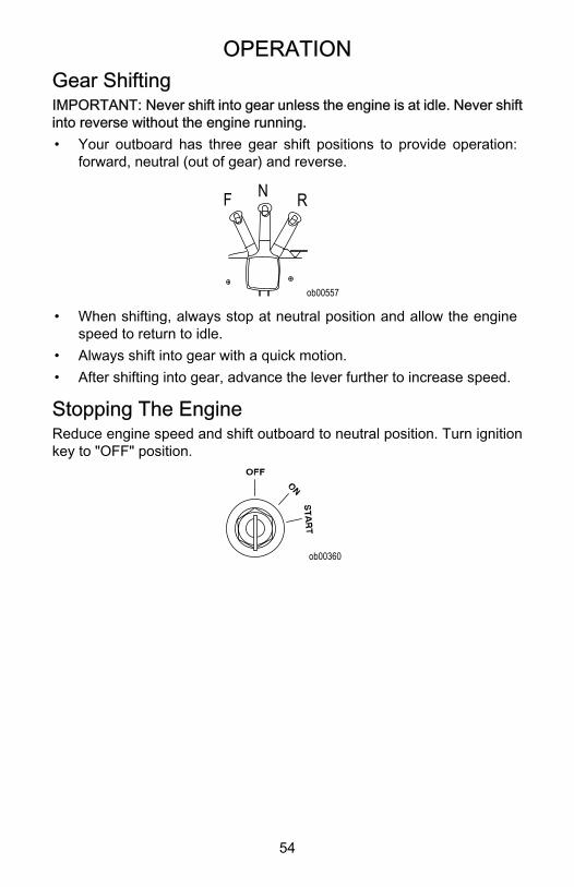
OPERATION
54
Gear ShiftingIMPORTANT: Never shift into gear unless the engine is at idle. Never shiftinto reverse without the engine running.• Your outboard has three gear shift positions to provide operation:
forward, neutral (out of gear) and reverse.
N RF
ob00557
• When shifting, always stop at neutral position and allow the enginespeed to return to idle.
• Always shift into gear with a quick motion.• After shifting into gear, advance the lever further to increase speed.
Stopping The EngineReduce engine speed and shift outboard to neutral position. Turn ignitionkey to "OFF" position.
ob00360
MAINTENANCE
55
Power Package Care
! WARNINGAvoid equipment damage, serious injury or death from improper orneglected maintenance, repairs or inspections of the power package. Ifyou are not familiar with proper maintenance or service procedures, havethe work performed by an authorized Mercury Marine dealer.
To ensure safety and retain dependability, keep your power package in thebest operating condition by performing the periodic inspections andmaintenance listed in the Inspection and Maintenance Schedule. Recordmaintenance performed in the Maintenance Log at the back of this book.Save all maintenance work orders and receipts.
Submerged Power PackageA submerged power package requires prompt service by an authorizeddealer after recovery. This immediate attention is necessary once theengine is exposed to the atmosphere to minimize internal corrosiondamage to the engine.
Replacement Parts for Your Power Package
! WARNINGUsing a replacement part that is inferior to the original part could resultin personal injury, death, or product failure.
Mercury recommends using original Mercury Precision replacement partsand lubricants.
EPA Emissions RegulationsAll new outboards manufactured by Mercury Marine are certified to theUnited States Environmental Protection Agency, as conforming to therequirements of the regulations for the control of air pollution from newoutboard motors. This certification is contingent on certain adjustments setto factory standards. For this reason, the factory procedure for servicingthe product must be strictly followed and, wherever practicable, returnedto the original intent of the design. Maintenance, replacement, or repair ofthe emission control devices and systems may be performed by any marinespark ignition (SI) engine repair establishment or individual.
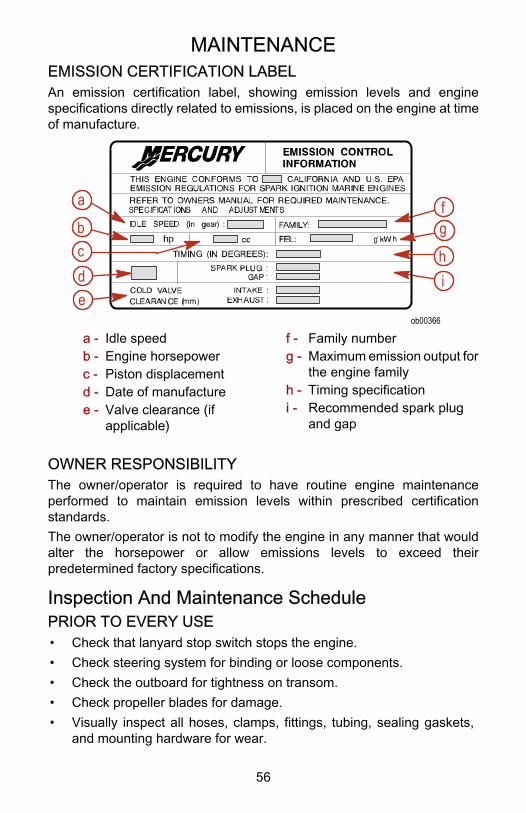
MAINTENANCE
56
EMISSION CERTIFICATION LABELAn emission certification label, showing emission levels and enginespecifications directly related to emissions, is placed on the engine at timeof manufacture.
ob00366
c hde
b
a f
i
g
a - Idle speedb - Engine horsepowerc - Piston displacementd - Date of manufacturee - Valve clearance (if
applicable)
f - Family numberg - Maximum emission output for
the engine familyh - Timing specificationi - Recommended spark plug
and gap
OWNER RESPONSIBILITYThe owner/operator is required to have routine engine maintenanceperformed to maintain emission levels within prescribed certificationstandards.The owner/operator is not to modify the engine in any manner that wouldalter the horsepower or allow emissions levels to exceed theirpredetermined factory specifications.
Inspection And Maintenance SchedulePRIOR TO EVERY USE• Check that lanyard stop switch stops the engine.• Check steering system for binding or loose components.• Check the outboard for tightness on transom.• Check propeller blades for damage.• Visually inspect all hoses, clamps, fittings, tubing, sealing gaskets,
and mounting hardware for wear.
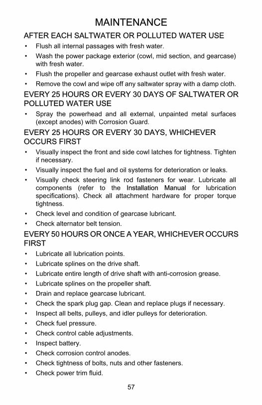
MAINTENANCE
57
AFTER EACH SALTWATER OR POLLUTED WATER USE• Flush all internal passages with fresh water.• Wash the power package exterior (cowl, mid section, and gearcase)
with fresh water.• Flush the propeller and gearcase exhaust outlet with fresh water.• Remove the cowl and wipe off any saltwater spray with a damp cloth.EVERY 25 HOURS OR EVERY 30 DAYS OF SALTWATER ORPOLLUTED WATER USE• Spray the powerhead and all external, unpainted metal surfaces
(except anodes) with Corrosion Guard.EVERY 25 HOURS OR EVERY 30 DAYS, WHICHEVEROCCURS FIRST• Visually inspect the front and side cowl latches for tightness. Tighten
if necessary.• Visually inspect the fuel and oil systems for deterioration or leaks.• Visually check steering link rod fasteners for wear. Lubricate all
components (refer to the Installation Manual for lubricationspecifications). Check all attachment hardware for proper torquetightness.
• Check level and condition of gearcase lubricant.• Check alternator belt tension.EVERY 50 HOURS OR ONCE A YEAR, WHICHEVER OCCURSFIRST• Lubricate all lubrication points.• Lubricate splines on the drive shaft.• Lubricate entire length of drive shaft with anti‑corrosion grease.• Lubricate splines on the propeller shaft.• Drain and replace gearcase lubricant.• Check the spark plug gap. Clean and replace plugs if necessary.• Inspect all belts, pulleys, and idler pulleys for deterioration.• Check fuel pressure.• Check control cable adjustments.• Inspect battery.• Check corrosion control anodes.• Check tightness of bolts, nuts and other fasteners.• Check power trim fluid.
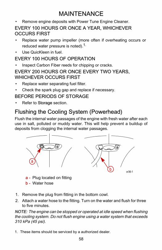
MAINTENANCE
58
• Remove engine deposits with Power Tune Engine Cleaner.EVERY 100 HOURS OR ONCE A YEAR, WHICHEVEROCCURS FIRST• Replace water pump impeller (more often if overheating occurs or
reduced water pressure is noted).1.
• Use QuicKleen in fuel.EVERY 100 HOURS OF OPERATION• Inspect Carbon Fiber reeds for chipping or cracks.EVERY 200 HOURS OR ONCE EVERY TWO YEARS,WHICHEVER OCCURS FIRST• Replace water separating fuel filter.• Check the spark plug gap and replace if necessary.BEFORE PERIODS OF STORAGE• Refer to Storage section.
Flushing the Cooling System (Powerhead)Flush the internal water passages of the engine with fresh water after eachuse in salt, polluted or muddy water. This will help prevent a buildup ofdeposits from clogging the internal water passages.
a
b or36-1
a - Plug located on fittingb - Water hose
1. Remove the plug from fitting in the bottom cowl.2. Attach a water hose to the fitting. Turn on the water and flush for three
to five minutes.NOTE: The engine can be stopped or operated at idle speed when flushingthe cooling system. Do not flush engine using a water system that exceeds310 kPa (45 psi).
1. These items should be serviced by a authorized dealer.
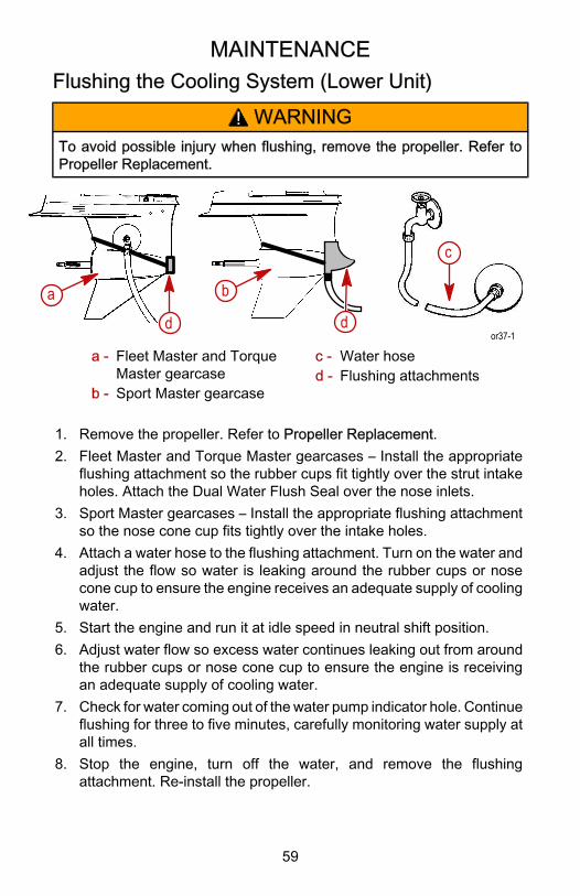
MAINTENANCE
59
Flushing the Cooling System (Lower Unit)
! WARNINGTo avoid possible injury when flushing, remove the propeller. Refer toPropeller Replacement.
a b
c
d dor37-1
a - Fleet Master and TorqueMaster gearcase
b - Sport Master gearcase
c - Water hosed - Flushing attachments
1. Remove the propeller. Refer to Propeller Replacement.2. Fleet Master and Torque Master gearcases – Install the appropriate
flushing attachment so the rubber cups fit tightly over the strut intakeholes. Attach the Dual Water Flush Seal over the nose inlets.
3. Sport Master gearcases – Install the appropriate flushing attachmentso the nose cone cup fits tightly over the intake holes.
4. Attach a water hose to the flushing attachment. Turn on the water andadjust the flow so water is leaking around the rubber cups or nosecone cup to ensure the engine receives an adequate supply of coolingwater.
5. Start the engine and run it at idle speed in neutral shift position.6. Adjust water flow so excess water continues leaking out from around
the rubber cups or nose cone cup to ensure the engine is receivingan adequate supply of cooling water.
7. Check for water coming out of the water pump indicator hole. Continueflushing for three to five minutes, carefully monitoring water supply atall times.
8. Stop the engine, turn off the water, and remove the flushingattachment. Re‑install the propeller.
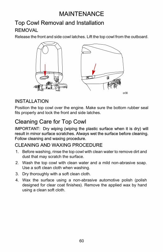
MAINTENANCE
60
Top Cowl Removal and InstallationREMOVALRelease the front and side cowl latches. Lift the top cowl from the outboard.
or38
INSTALLATIONPosition the top cowl over the engine. Make sure the bottom rubber sealfits properly and lock the front and side latches.
Cleaning Care for Top CowlIMPORTANT: Dry wiping (wiping the plastic surface when it is dry) willresult in minor surface scratches. Always wet the surface before cleaning.Follow cleaning and waxing procedure.CLEANING AND WAXING PROCEDURE1. Before washing, rinse the top cowl with clean water to remove dirt and
dust that may scratch the surface.2. Wash the top cowl with clean water and a mild non‑abrasive soap.
Use a soft clean cloth when washing.3. Dry thoroughly with a soft clean cloth.4. Wax the surface using a non‑abrasive automotive polish (polish
designed for clear coat finishes). Remove the applied wax by handusing a clean soft cloth.
MAINTENANCE
61
Fuel SystemFUEL SYSTEM SERVICE INFORMATION
! WARNINGAvoid serious injury or death from gasoline fire or explosion. Carefullyfollow all fuel system service instructions. Always stop the engine and donot smoke or allow open flames or sparks in the area while servicing anypart of the fuel system.
IMPORTANT: Use an approved container to collect and store fuel. Wipeup any spillage immediately. Material used to contain spillage must bedisposed of in an approved receptacle.Before servicing any part of the fuel system:• Stop engine and disconnect the battery.• Drain the fuel system completely.• Perform fuel system service in a well ventilated area.• Inspect any completed service work for sign of fuel leakage.
FUEL LINE INSPECTIONVisually inspect the fuel line and primer bulb for cracks, swelling, leaks,hardness, or other signs of deterioration or damage. If any of theseconditions are found, the fuel line or primer bulb must be replaced.
WATER SEPARATING FUEL FILTERThis filter removes moisture and debris from the fuel. If the filter becomesfilled with water, the water can be removed. If the filter becomes pluggedwith debris, replace the filter. The warning system engages when water inthe fuel filter reaches the full level. Refer to Warning System in Features &Controls.Refer to the Inspection and Maintenance Schedule for the propermaintenance interval.
MAINTENANCE
62
Removal
or39-1
ab
c
a - O‑ring sealsb - Filterc - Raised bosses
1. Disconnect the link rod.2. Use the shaft of a screwdriver between the filter cap bosses and
unscrew the filter.Installation1. Lubricate the o‑ring seals with oil.2. Install the fuel filter and tighten securely.3. Reconnect the link rod.IMPORTANT: Visually inspect for fuel leakage from the filter whilesqueezing the primer bulb until firm, forcing fuel into the filter.
MAINTENANCE
63
DRAINING WATER FROM THE FUEL FILTER CHAMBERNOTE: If a sufficient amount of water has accumulated in the fuel filterchamber, the warning system will turn on. Draining the water from the fuelfilter chamber is required.1. Pull the drain hose off the right side fitting. Hold open end of the hose
over a container.2. Loosen drain screw and drain the fuel filter chamber.NOTE: If little or no liquid drains from the hose, loosen the red filter to ventthe chamber.3. Retighten drain screw and reattach hose.
ob01679
a bc
a - Drain hoseb - Side fittingc - Drain screw
IMPORTANT: Visually inspect for fuel leakage from the drain screw bysqueezing the primer bulb until firm, forcing fuel into the chamber.
Steering Link Rod FastenersIMPORTANT: The steering link rod that connects the steering cables tothe engine must be fastened using special washer head bolt (P/N10‑849838) and self‑locking nylon insert locknuts (P/N 11‑826709113).Never replace locknuts with common nuts (non‑locking) as they will workloose/vibrate off freeing link rod to disengage.
MAINTENANCE
64
! WARNINGDisengagement of a steering link rod can result in the boat taking a full,sudden, sharp turn. This potentially violent action can cause occupantsto be thrown overboard exposing them to serious injury or death.
! WARNINGAvoid equipment damage, serious injury or death. Visually inspect allsteering attachment components for wear, lubricate all attachmenthardware, and check for proper torque tightness in accordance with theinspection and maintenance schedule.
or79
a
b
c
d
a - Special washer head bolt(P/N 10‑849838)
b - Nylon Locknut ‑ used onhead bolt (P/N11‑826709113)
c - Flat washer (2)d - Nylon Locknut ‑ used on
cable coupler (P/N11‑826709113)
1. Assemble steering link rod to steering cable coupler with two flatwashers "c" and a self‑locking nylon insert locknut "d." Tighten thelocknut until it seats, then loosen ¼ turn.
2. Assemble the steering link rod to the engine with the special washerhead bolt "a" and self locking nylon insert locknut "b."
3. Torque the head bolt, then the locknut to specifications.
Description Nm lb. in. lb. ft.
Cable Coupler Nylon Locknut "d" Tighten locknut until it seats, thenloosen ¼ turn.
Head Bolt Nylon Locknut "b" 27 20
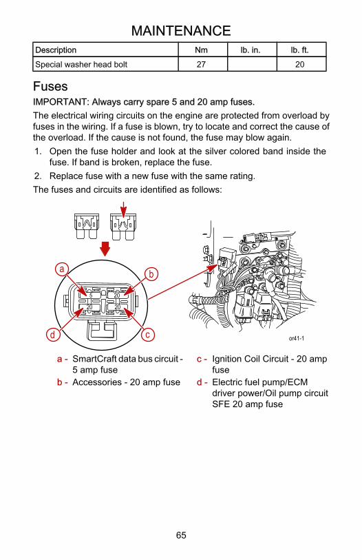
MAINTENANCE
65
Description Nm lb. in. lb. ft.
Special washer head bolt 27 20
FusesIMPORTANT: Always carry spare 5 and 20 amp fuses.The electrical wiring circuits on the engine are protected from overload byfuses in the wiring. If a fuse is blown, try to locate and correct the cause ofthe overload. If the cause is not found, the fuse may blow again.1. Open the fuse holder and look at the silver colored band inside the
fuse. If band is broken, replace the fuse.2. Replace fuse with a new fuse with the same rating.The fuses and circuits are identified as follows:
5
20 20
20
a b
cd or41-1
a - SmartCraft data bus circuit ‑5 amp fuse
b - Accessories ‑ 20 amp fuse
c - Ignition Coil Circuit ‑ 20 ampfuse
d - Electric fuel pump/ECMdriver power/Oil pump circuitSFE 20 amp fuse
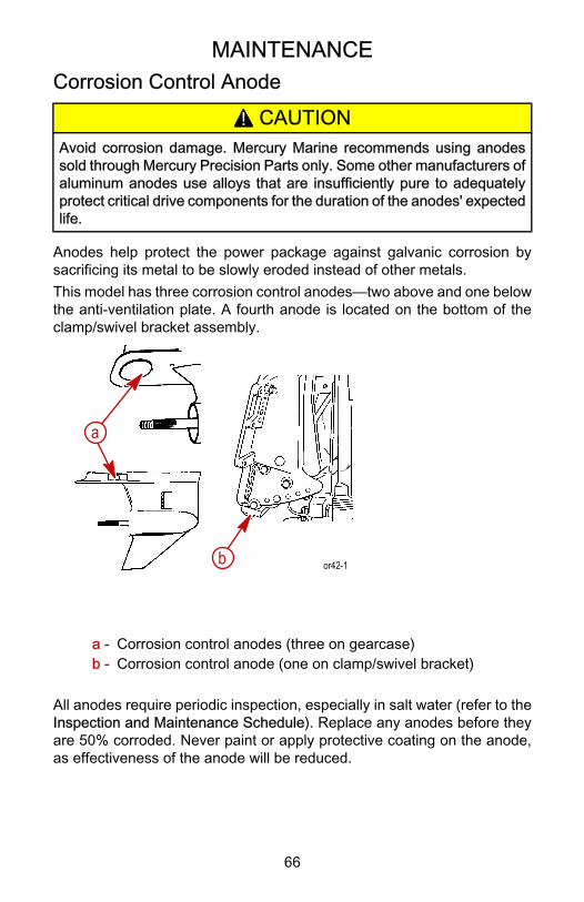
MAINTENANCE
66
Corrosion Control Anode
! CAUTIONAvoid corrosion damage. Mercury Marine recommends using anodessold through Mercury Precision Parts only. Some other manufacturers ofaluminum anodes use alloys that are insufficiently pure to adequatelyprotect critical drive components for the duration of the anodes' expectedlife.
Anodes help protect the power package against galvanic corrosion bysacrificing its metal to be slowly eroded instead of other metals.This model has three corrosion control anodes—two above and one belowthe anti‑ventilation plate. A fourth anode is located on the bottom of theclamp/swivel bracket assembly.
or42-1
a
b
a - Corrosion control anodes (three on gearcase)b - Corrosion control anode (one on clamp/swivel bracket)
All anodes require periodic inspection, especially in salt water (refer to theInspection and Maintenance Schedule). Replace any anodes before theyare 50% corroded. Never paint or apply protective coating on the anode,as effectiveness of the anode will be reduced.
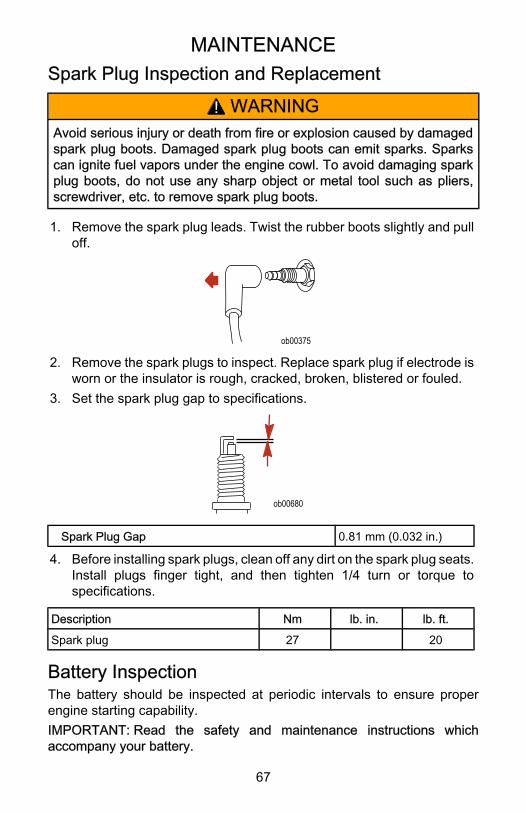
MAINTENANCE
67
Spark Plug Inspection and Replacement
! WARNINGAvoid serious injury or death from fire or explosion caused by damagedspark plug boots. Damaged spark plug boots can emit sparks. Sparkscan ignite fuel vapors under the engine cowl. To avoid damaging sparkplug boots, do not use any sharp object or metal tool such as pliers,screwdriver, etc. to remove spark plug boots.
1. Remove the spark plug leads. Twist the rubber boots slightly and pulloff.
ob00375
2. Remove the spark plugs to inspect. Replace spark plug if electrode isworn or the insulator is rough, cracked, broken, blistered or fouled.
3. Set the spark plug gap to specifications.
ob00680
Spark Plug Gap 0.81 mm (0.032 in.)
4. Before installing spark plugs, clean off any dirt on the spark plug seats.Install plugs finger tight, and then tighten 1/4 turn or torque tospecifications.
Description Nm lb. in. lb. ft.
Spark plug 27 20
Battery InspectionThe battery should be inspected at periodic intervals to ensure properengine starting capability.IMPORTANT: Read the safety and maintenance instructions whichaccompany your battery.
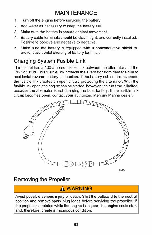
MAINTENANCE
68
1. Turn off the engine before servicing the battery.2. Add water as necessary to keep the battery full.3. Make sure the battery is secure against movement.4. Battery cable terminals should be clean, tight, and correctly installed.
Positive to positive and negative to negative.5. Make sure the battery is equipped with a nonconductive shield to
prevent accidental shorting of battery terminals.
Charging System Fusible LinkThis model has a 100 ampere fusible link between the alternator and the+12 volt stud. This fusible link protects the alternator from damage due toaccidental reverse battery connection. If the battery cables are reversed,the fusible link creates an open circuit, protecting the alternator. With thefusible link open, the engine can be started; however, the run time is limited,because the alternator is not charging the boat battery. If the fusible linkcircuit becomes open, contact your authorized Mercury Marine dealer.
59364
Removing the Propeller
! WARNINGAvoid possible serious injury or death. Shift the outboard to the neutralposition and remove spark plug leads before servicing the propeller. Ifthe propeller is rotated while the engine is in gear, the engine could startand, therefore, create a hazardous condition.
MAINTENANCE
69
NOTE: If propeller is seized to the shaft and cannot be removed, consultyour authorized Mercury Marine dealer.1. Shift outboard to neutral.
N
ob00351
2. Remove the spark plug leads to prevent the engine from starting.
ob00375
3. Straighten the bent tabs on the propeller nut retainer (if applicable).4. Place a block of wood between the gearcase and the propeller to hold
the propeller and remove the propeller nut.
ob00377
5. Remove the propeller and associated hardware from the propellershaft.
Installing the Propeller (19 Spline Shafts)
! WARNINGAvoid serious personal injury or death. Remove the key from the ignitionswitch, disconnect the lanyard stop switch, and remove the spark plugleads to ensure that the engine does not accidentally start.
MAINTENANCE
70
! CAUTIONAvoid engine damage. Prop the engine so engine speed is limited to therequired full throttle rpm range. An under‑propped engine mayoccasionally initiate the rev limiter. This may result in internal powerheaddamage.
Applications using 19 spline propeller shafts require the Heavy‑DutyPropeller Hub kit, included with most Mercury Racing propellers.Before installing the propeller:1. Set the remote control into the neutral position.2. Remove the keys from the ignition and engage the safety stop switch.3. Coat the propeller shaft with Anti‑Corrosion Grease.IMPORTANT: To prevent the propeller hub from corroding and seizing tothe propeller shaft, especially in salt water, always apply a coat of therecommended lubricant to the entire propeller shaft at the recommendedmaintenance intervals and also each time the propeller is removed.To install a propeller for use with a 19 spine propeller shaft:1. Lubricate the propeller shaft splines.2. Install the propeller hub assembly, propeller, washer, Belleville
washer, washer, and propeller nut onto the propeller shaft.
94
a
b
c f
d e
2693
a - Propeller hub assemblyb - Propellerc - Washer
d - Belleville washere - Washerf - Propeller nut
MAINTENANCE
71
Tube Ref No. Description Where Used Part No.
94 Anti-Corrosion Grease Propeller shaft splines 92-802867A1
3. Place a block of wood between the gearcase and propeller and torquethe propeller nut.
or119
Description Nm lb. in. lb. ft.
Propeller nut 75 55
4. Place the safety stop switch into the "RUN" position.
MAINTENANCE
72
Lubrication Points
5517
3494
9595
95
Tube Ref. No. Description Where Used Part Number
34 Special Lubricant 101 Trim Rod Ball Ends 92‑802865A1
95 2‑4‑C with Teflon
Prop Shaft
92‑802859A1Swivel Bracket
Tilt Support Lever
Tilt Tube
NOTE: Turn the ball ends to work the lubricant into the ball sockets.Lubricate through fittings
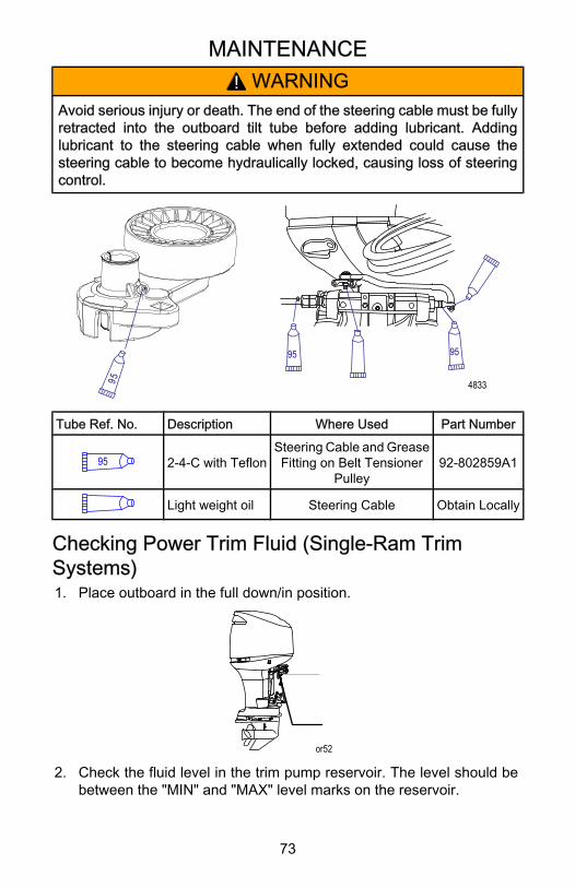
MAINTENANCE
73
! WARNINGAvoid serious injury or death. The end of the steering cable must be fullyretracted into the outboard tilt tube before adding lubricant. Addinglubricant to the steering cable when fully extended could cause thesteering cable to become hydraulically locked, causing loss of steeringcontrol.
4833
95
95
95
Tube Ref. No. Description Where Used Part Number
95 2‑4‑C with TeflonSteering Cable and GreaseFitting on Belt Tensioner
Pulley92‑802859A1
Light weight oil Steering Cable Obtain Locally
Checking Power Trim Fluid (Single‑Ram TrimSystems)1. Place outboard in the full down/in position.
or52
2. Check the fluid level in the trim pump reservoir. The level should bebetween the "MIN" and "MAX" level marks on the reservoir.
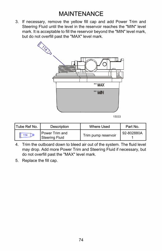
MAINTENANCE
74
3. If necessary, remove the yellow fill cap and add Power Trim andSteering Fluid until the level in the reservoir reaches the "MIN" levelmark. It is acceptable to fill the reservoir beyond the "MIN" level mark,but do not overfill past the "MAX" level mark.
114
15033
Tube Ref No. Description Where Used Part No.
114 Power Trim andSteering Fluid Trim pump reservoir 92-802880A
1
4. Trim the outboard down to bleed air out of the system. The fluid levelmay drop. Add more Power Trim and Steering Fluid if necessary, butdo not overfill past the "MAX" level mark.
5. Replace the fill cap.
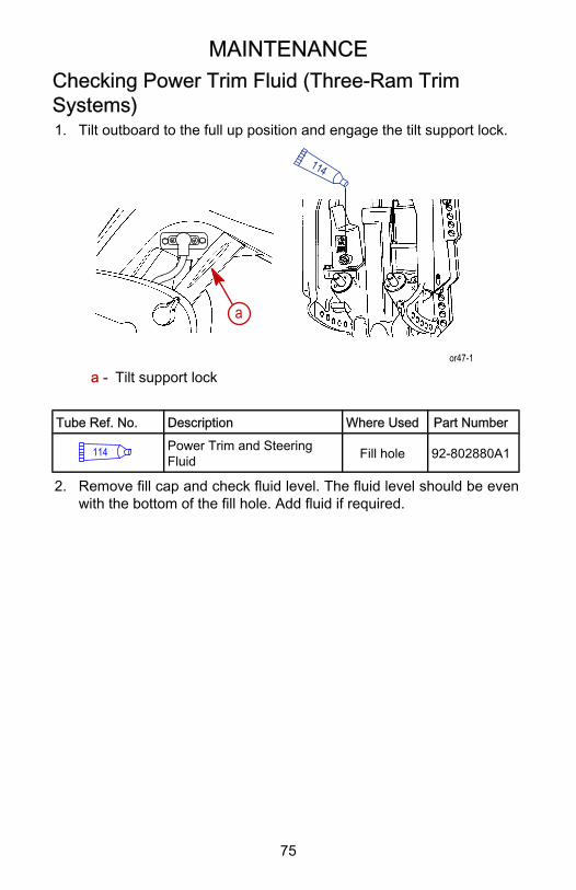
MAINTENANCE
75
Checking Power Trim Fluid (Three‑Ram TrimSystems)1. Tilt outboard to the full up position and engage the tilt support lock.
a
114
or47-1
a - Tilt support lock
Tube Ref. No. Description Where Used Part Number
114 Power Trim and SteeringFluid Fill hole 92‑802880A1
2. Remove fill cap and check fluid level. The fluid level should be evenwith the bottom of the fill hole. Add fluid if required.

MAINTENANCE
76
Gearcase LubricantCHECKING/REFILLING GEARCASE LUBRICANT
or49-1
a b
cd
e
f
cd
87
a - SportMaster gearcase(vertical operating position)
b - Fleet/Torque Mastergearcase (verticaloperating position)
c - Vent hole
d - Vent plug and sealing washere - Fill/drain holef - Fill/drain plug
Tube Ref. No. Description Where Used Part Number
87 High Performance Gear Lube Fill/Drain Hole 92‑802854A1
1. Place the outboard in a vertical operating position.2. Remove the vent plug (upper plug) and sealing washer.3. Remove the fill/drain plug (lower plug).4. Quickly place lubricant tube into the fill hole.5. Slowly add lubricant until it flows from the (upper) vent hole.6. Stop adding lubricant. Install the (upper) vent plug and sealing washer
before removing the lubricant tube.IMPORTANT: Replace sealing washers if damaged.NOTE: Examine the magnetic fill/drain plug for metal particles. A smallamount of metal filings or fine metal particles indicates normal gear wear.An excessive amount of metal filings or larger particles (chips) should bechecked by an authorized dealer.

MAINTENANCE
77
7. Remove lubricant tube and reinstall cleaned (lower) fill/drain plug andsealing washer.
Water in gear lubricant may:• Settle to bottom and drain out with the lubricant• Be mixed with lubricant giving a milky color to lubricantWater in gear lubricant will:• Result in premature bearing failure• In freezing temperatures, turn to ice and damage gearcaseDRAINING THE GEARCASE
or50-1
a bc c
d
e
a - SportMaster Gearcase(vertical operating position)
b - Fleet/Torque Mastergearcase (verticaloperating position)
c - Vent plug and sealing ring
d - Fill/Drain plug and sealingring
e - Drain pan
1. Place the outboard in a vertical operating position.2. Place a drain pan below outboard.3. Remove the vent plug (upper plug) and sealing ring.4. Remove the fill/drain plug (lower plug) and sealing ring and drain
lubricant.GEARCASE LUBRICANT CAPACITYGearcase lubricant capacity is approximately 710 ml (24 oz).
STORAGE
78
Storage PreparationThe major consideration in preparing your outboard for storage is to protectit from rust, corrosion, and damage caused by freezing of trapped water.The following storage procedures should be followed to prepare youroutboard for out of season storage or prolonged storage (two months orlonger).
! CAUTIONNever start or operate your outboard (even momentarily) without watercirculating through all the cooling water intake holes in the gearcase toprevent damage to the water pump (running dry) or overheating of theengine.
FUEL SYSTEMIMPORTANT: Gasoline containing alcohol (ethanol or methanol) cancause a formation of acid during storage and can damage the fuel system.If the gasoline being used contains alcohol, it is advisable to drain as muchof the remaining gasoline as possible from the fuel tank, remote fuel line,and engine fuel system.The most effective method for storage preparation is to add therecommended amount of Mercury Precision Fuel Stabilizer and MercuryPrecision Quickleen products as described on their containers to the fueltank before the last operation of the boat. Adding Fuel Stabilizer will helpprevent the formation of varnish and gum in the gasoline. The MercuryPrecision Quickleen product will help clean and lubricate the fuel injectors.1. Portable Fuel Tank ‑ Pour the required amount of gasoline stabilizer
(follow instructions on container) into fuel tank. Tip fuel tank back andforth to mix stabilizer with the fuel.
2. Permanently Installed Fuel Tank ‑ Pour the required amount ofgasoline stabilizer (follow instructions on container) into a separatecontainer and mix with approximately one quart (one liter) of gasoline.Pour this mixture into fuel tank.
3. Pull the drain hose off the right side fitting. Hold the open end of thehose over a container. Loosen drain screw and drain the fuel filterchamber.

STORAGE
79
NOTE: If little or no liquid drains from the hose, loosen the red filter to ventthe chamber.
ob01352
a
b
c
a - Drain screwb - Drain hosec - Right side fitting
4. Re‑tighten drain screw and re‑attach hose.5. Pull the drain hose off the left side fitting. Hold the open end of the
hose over a container and loosen drain screw and drain the floatchamber. Re‑tighten drain screw and re‑attach hose.
c
a
ob01589
b
a - Left side fittingb - Drain screwc - Drain hose
STORAGE
80
6. Premix the following in a container:• 8 cc (0.27 oz.) or 2 teaspoons of Mercury Precision Quickleen
lubricant.• 8 cc (0.27 oz.) or 2 teaspoons of Mercury Precision Fuel Stabilizer.
7. Remove the fuel filter. Refer to Maintenance ‑ Fuel System.8. Pour mixture into the fuel filter opening.9. Reinstall the fuel filter.10. Prime the fuel system as outlined in the Operation ‑ Starting the
Engine.11. Place the outboard in water or use the flushing attachment for
circulating cooling water. Start the engine and run at idle speed for 5minutes to allow the treated fuel to fill the fuel system.
Protecting Internal Engine ComponentsNOTE: Make sure the fuel system has been prepared for storage. Refer toFuel System, preceeding.IMPORTANT: Refer to Spark Plug Inspection and Replacement for correctprocedure for removing spark plug leads.1. Remove the spark plugs and add approximately 30 ml (1 oz.) of
engine oil into each spark plug hole.2. Rotate the flywheel manually several times to distribute the oil in the
cylinders.3. Re‑install spark plugs.
Protecting External Outboard Components• Lubricate all outboard components listed in Maintenance ‑ Inspection
and Maintenance Schedule.• Touch up any paint nicks. See your dealer for touch‑up paint.• Spray Quicksilver or Mercury Precision Lubricants Corrosion Guard
on external metal surfaces (except corrosion control anodes).
Tube Ref No. Description Where Used Part No.
120 Corrosion Guard External metalsurfaces
92-802878-55
Gearcase• Drain and refill the gearcase lubricant (refer to Maintenance ‑
Gearcase Lubrication).
STORAGE
81
Positioning Outboard For StorageStore outboard in an upright (vertical) position to allow water to drain outof outboard.
! CAUTIONIf outboard is stored tilted up in freezing temperature, trapped coolingwater or rain water that may have entered the propeller exhaust outlet inthe gearcase could freeze and cause damage to the outboard.
Battery Storage• Follow the battery manufacturer's instructions for storage and
recharging.• Remove the battery from the boat and check water level. Recharge if
necessary.• Store the battery in a cool, dry place.• Periodically check the water level and recharge the battery during
storage.
TROUBLESHOOTING
82
Starter Motor Will Not Crank the EnginePOSSIBLE CAUSES• Blown 20 amp fuse in the starting circuit. Refer to Maintenance.• Outboard is not shifted to neutral position.• Weak battery or battery connections are loose or corroded.• Ignition key switch failure.• Wiring or electrical connection faulty.• Starter motor solenoid or slave solenoid failure.
Engine Will Not StartPOSSIBLE CAUSES• Lanyard stop switch not in "RUN" position.• Battery not fully charged.• Incorrect starting procedure. Refer to Operation section.• Old or contaminated fuel.• Fuel is not reaching the engine.
• Fuel tank is empty.• Fuel tank vent not open or restricted.• Fuel line is disconnected or kinked.• Primer bulb not squeezed.• Primer bulb check valve is faulty.• Fuel filter is obstructed. Refer to Maintenance section.• Fuel pump failure.• Fuel tank filter obstructed.
• Open 20 amp fuse. Check fuses, refer to Maintenance section.• Threaded connection of an air hose is loose.• Ignition system component failure.• Spark plugs fouled or defective. Refer to Maintenance section.
Engine Runs ErraticallyPOSSIBLE CAUSES• Spark plugs fouled or defective. Refer to Maintenance section.• Incorrect setup and adjustments.• Fuel is being restricted to the engine.
a. Engine fuel filter is obstructed. Refer to Maintenance section.
TROUBLESHOOTING
83
b. Fuel tank filter obstructed.c. Stuck anti‑siphon valve on built in fuel tank.d. Fuel line is kinked or pinched.e. Injector plugged.
• Threaded connection of an air hose is loose.• Fuel pump failure.• Ignition system component failure.
Performance LossPOSSIBLE CAUSES• Throttle not opening fully.• Damaged propeller or improper propeller size.• Boat overloaded or load improperly distributed.• Excessive water in bilge.• Boat bottom is dirty or damaged.• Warning horn failure.• Engine block pressure sensor or coolant temperature sensor failure
(Guardian is activated).
Warning Horn Activates (With Power Loss)POSSIBLE CAUSES• Intermittent horn sound:
• The oil level in the engine‑mounted oil reservoir tank is low. Refillthe reservoir tank and the remote oil tank. Refer to Fuel and Oil fordetails.
• Battery voltage is out of limits.• Throttle position sensor failure.
• Continuous horn sound:• The oil level in the engine‑mounted oil reservoir tank is critically
low. Refill the reservoir tank and the remote oil tank. Refer to Fueland Oil for details.
• The oil pump has failed, halting the oil supply to the engine.• Engine speed exceeds the maximum‑allowable RPM. The system
limits the engine to within the allowable range. If the overspeedcondition continues, Guardian places the engine into powerreduction. Overspeed may be caused by incorrect propeller pitch,engine height, trim angle, etc.
TROUBLESHOOTING
84
• High engine temperature or low block water pressure.• Cooling system clogged.• Incorrect transom height (water pickups not getting adequate
water supply).
Warning Horn Activates (No Power Loss)POSSIBLE CAUSES• Warning horn activates on start up. This is normal operation.• Water is detected in the water‑separating fuel filter. Refer to
Maintenance for procedures on removing water from the filter.
Battery Will Not Hold ChargePOSSIBLE CAUSES• Battery connections are loose or corroded.• Low electrolyte level in battery.• Worn out or inefficient battery.• Excessive use of electrical accessories.• Defective rectifier, alternator, or voltage regulator.
OWNER SERVICE ASSISTANCE
85
Local Repair ServiceAlways return your outboard to your local authorized dealer should theneed for service arise. Only he has the factory trained mechanics,knowledge, special tools, equipment, and genuine parts and accessoriesto properly service your engine should the need occur. He knows yourengine best.
Service Away From HomeIf you are away from your local dealer and the need arises for service,contact the nearest authorized dealer. Refer to the Yellow Pages of thetelephone directory. If, for any reason, you cannot obtain service, contactthe nearest Mercury Marine Service Office.
Parts And Accessories InquiriesAll inquiries concerning genuine replacement parts and accessories shouldbe directed to your local authorized dealer. The dealer has the necessaryinformation to order parts and accessories for you. When inquiring on partsand accessories, the dealer requires the model and serial number to orderthe correct parts.
Service AssistanceYour satisfaction with your outboard product is very important to yourdealer and to us. If you ever have a problem, question or concern aboutyour outboard product, contact your dealer or any authorized MercuryMarine dealership. If additional assistance is required, take these steps.1. Talk with the dealership's sales manager or service manager. If this
has already been done, then contact the owner of the dealership.2. Should you have a question, concern, or problem that cannot be
resolved by your dealership, please contact Mercury Marine ServiceOffice for assistance. Mercury Marine will work with you and yourdealership to resolve all problems.
The following information will be needed by the service office:• Your name and address• Daytime telephone number• Model and serial number of your outboard• The name and address of your dealership• Nature of problem
OWNER SERVICE ASSISTANCE
86
Mercury Marine Service OfficesFor assistance, call, fax, or write. Please include your daytime telephonenumber with mail and fax correspondence.
United States
Telephone Fax Mercury MarineW6250 W. Pioneer RoadP.O. Box 1939Fond du Lac, WI 54936-1939
(920) 929‑5040 (920) 929‑5893
United States (Mercury Racing)
Telephone Fax Mercury RacingN7480 County Rd. UUFond du Lac, WI 54935-9585(920) 924‑2088 (920) 924‑2096
Canada
Telephone Fax Mercury Marine Ltd.2395 Meadowpine Blvd.Mississauga, Ontario L5N 7W6Canada
(905) 567‑6372 (905) 567‑8515
Australia, Pacific
Telephone Fax Mercury Marine Australia132-140 Frankston RoadDandenong, Victoria 3164Australia
(61) (3) 9791‑5822 (61) (3) 9793‑5880
OWNER SERVICE ASSISTANCE
87
Europe, Middle East, Africa
Telephone Fax Marine Power - Europe, Inc.Parc Industriel de Petit-RechainB-4800Verviers,Belgium
(32) (87) 32 • 32 • 11 (32) (87) 31 • 19 • 65
Mexico, Central America, South America, Caribbean
Telephone Fax Mercury Marine11650 Interchange Circle NorthMiramar, FL 33025U.S.A.
(954) 744‑3513 (954) 744‑3535
Japan
Telephone Fax Mercury Marine - Japan283-1 Anshin-cho HamamatsuShizuoka, 435-0005Japan
81‑53‑423‑2500 81‑53‑423‑2510
Asia, Singapore
Telephone Fax Mercury Marine Singapore72 Loyang WaySingapore, 5087625466160 5467789
Ordering LiteratureBefore ordering literature, please have the following information about yourpower package available:
Engine Model: Horsepower:
Serial Number: Model year:
UNITED STATES AND CANADAFor information on additional literature that is available for your particularMercury/MerCruiser power package and how to order that literature contactyour nearest dealer or contact:
MERCURY MARINE
Telephone Fax Mail
(920) 929‑5110 (920) 929‑4894
Mercury MarineAttn: Publications Department
P.O. Box 1939Fond du Lac, WI 54936-1939 ,
OWNER SERVICE ASSISTANCE
88
OUTSIDE THE UNITED STATES AND CANADAContact your nearest dealer or Marine Power Service Center forinformation on additional literature that is available for your particularMercury/MerCruiser power package and how to order that literature.
MAINTENANCE LOG
89
Maintenance LogRecord all maintenance performed on your outboard here. Be sure to saveall work orders and receipts.
Date Maintenance Performed Engine Hours