Embed Size (px)
Citation preview

WANDesign Summary
August 2014 Series
Table of Contents
Table of ContentsPreface ........................................................................................................................................1
Introduction ................................................................................................................................2
Business Overview ......................................................................................................................5Business Use Cases ................................................................................................................... 6
Use Case: Site-to-Site Communications Using MPLS L3VPN Services.................................. 6Use Case: Site–to-Site Communications using Layer 2 WAN Services .................................. 6Use Case: Secure Site-to-Site WAN Communications Using Internet Services ...................... 7Use Case: Site-to-Site Connectivity Using 3G/4G Wireless Services ..................................... 7Use Case: Local Internet Access from Remote Site ............................................................... 7Use Case: Optimization of Traffic Traversing the WAN ........................................................... 7
The Value of a Cohesive WAN Strategy to an Organization ....................................................... 8
WAN Architecture .......................................................................................................................9WAN Transport Technologies ...................................................................................................... 9
MPLS WAN using Layer 3 VPN .............................................................................................. 9Layer 2 WAN using Virtual Private LAN Services (VPLS) or Metro Ethernet ......................... 10Internet with VPN WAN ........................................................................................................ 10Dynamic Multipoint VPN ....................................................................................................... 10Internet 3G/4G with VPN WAN ..............................................................................................11Remote Site using Local Internet Access ...............................................................................11
Quality of Service ......................................................................................................................11WAN-Aggregation Design .........................................................................................................12WAN Remote-Site Design ..........................................................................................................13
MPLS WAN .......................................................................................................................... 15Layer 2 WAN .........................................................................................................................17VPN WAN .............................................................................................................................19VPN Remote Site over 3G/4G ............................................................................................... 25Remote-Site Using Local Internet ......................................................................................... 25Remote-Site Wired LAN ...................................................................................................... 29Remote-Site Wireless LAN ................................................................................................... 33Application Optimization Using Cisco WAAS ........................................................................ 36ISR-WAAS ............................................................................................................................ 40
Summary ...................................................................................................................................41

Preface August 2014 Series1
PrefaceCisco Validated Designs (CVDs) present systems that are based on common use cases or engineering priorities. CVDs incorporate a broad set of technologies, features, and applications that address customer needs. They incorporate a broad set of technologies, features, and applications to address customer needs. Cisco engineers have comprehensively tested and documented each CVD in order to ensure faster, more reliable, and fully predictable deployment.
This design summary provides information about the use cases covered in a series or set of related CVD guides and summarizes the Cisco products and technologies that solve the challenges presented by the use cases.
CVD Foundation SeriesThis CVD Foundation guide is a part of the August 2014 Series. As Cisco develops a CVD Foundation series, the guides themselves are tested together, in the same network lab. This approach assures that the guides in a series are fully compatible with one another. Each series describes a lab-validated, complete system.
The CVD Foundation series incorporates wired and wireless LAN, WAN, data center, security, and network management technologies. Using the CVD Foundation simplifies system integration, allowing you to select solutions that solve an organization’s problems—without worrying about the technical complexity.
To ensure the compatibility of designs in the CVD Foundation, you should use guides that belong to the same release. For the most recent CVD Foundation guides, please visit the CVD Foundation web site.
Comments and QuestionsIf you would like to comment on a guide or ask questions, please use the feedback form.

Introduction August 2014 Series2
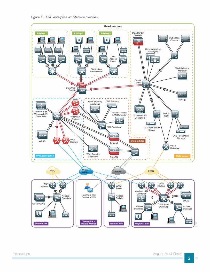
Introduction The enterprise series of Cisco Validated Designs (CVDs) is a comprehensive design that incorporates LAN, WAN, security, application optimization, data center, and unified communications technologies in order to provide a complete solution for an organization’s business challenges. The enterprise WAN architecture interconnects remote-site LANs to a primary site LAN or data center by using a variety of WAN technologies, including Multiprotocol Label Switching (MPLS), Layer 2 WAN, and VPN WAN over the Internet. CVD enterprise WAN is designed to support multiple resiliency options depending on the business requirements for the remote sites.
The WAN design methodology provides network access for remote sites that have wired and wireless users, ranging from small remote sites with a few connected users to large sites with up to 5,000 connected users.
CVD enterprise WAN is the foundation for interconnecting remote sites to the primary sites or data centers, providing connectivity for users to the applications they require to do their job. The WAN plays a critical role in providing reliable and scalable interconnections to a broad range of remote sites.
Introduction August 2014 Series3
Figure 1 - CVD enterprise architecture overview
21
89Remote Site Regional SiteRemote Site
Teleworker /Mobile Worker
AccessSwitches
AccessSwitches
WANRouters
Cisco WAASWAAS
WANRoutersWAN
Router
AccessSwitch
Hardware andSoftware VPN
Wireless LANController
DistributionSwitchesAccess
Switches
WAN Aggregation
Internet Edge
Data Center
Headquarters
WANRoutersWAAS
VPN WANRouters
Remote-SiteWireless LAN
Controllers
UCS Rack-mountServers
UCS Rack-mountServer
Wireless LANControllers
Email SecurityAppliance
Firewall
RA-VPNWeb Security
Appliance
Guest WirelessLAN Controller
Data CenterFirewalls
CommunicationsManagers
UCS BladeChassis
DMZ Servers
DMZ Switches
Nexus2000
Storage
WAAS CentralManager
Nexus5500
UserAccessLayer
InternetPSTN PSTNMPLSWANs
Building 1 Building 2 Building 3
Core VSSSwitch
DistributionSwitch Layer
VoiceGateway
Introduction August 2014 Series4
Cisco tests network and user devices connected together to simulate an end-to-end deployment for your organization. This solution-level approach reduces the risk of interoperability problems between different technologies and components, allowing the customer to select the parts needed to solve a business problem. Where appropriate, the architecture provides multiple options based on network scalability or service-level requirements.
Cisco designed, built, and tested this architecture with the following goals:
• Ease of deployment—Organizations can deploy the solution consistently across all products included in the design. The reference configurations used in the deployment represent a best-practice methodology that enables a fast and resilient deployment.
• Flexibility and scalability—The architecture is modular so that organizations can select what they need when they need it, and it is designed to grow with the organization without requiring costly forklift upgrades.
• Resiliency and security—The design removes network borders in order to increase usability while protecting user traffic. It also keeps the network operational even during attacks or unplanned outages.
• Ease of management—Deployment and configuration guidance includes configuration examples of management by a network management system or by unique network element managers.
• Advanced technology ready—The network foundation allows easier implementation of advanced technologies such as collaboration.

Business Overview August 2014 Series5
Business OverviewData networks are critical to an organization’s viability and productivity. Online workforce-enablement tools are only beneficial if the data network provides reliable access to information resources. The number of users and locations in an organization can vary dramatically as an organization grows and adapts to changes in business activity. Providing a consistent user experience when users connect to the network increases their productivity. Whether users are sitting in an office at headquarters or working from a remote site, they require transparent access to the applications and files in order to perform their jobs.
For remote-site users to effectively support the business, organizations require that the WAN provide sufficient performance and reliability. Because most of the applications and services that the remote-site worker uses are centrally located, the WAN design must provide a common resource access experience to the workforce regardless of location.
To control operational costs, the WAN must support the convergence of voice, video, and data transport onto a single, centrally managed infrastructure. As organizations move into multinational or global business markets, they require a flexible network design that allows for country-specific access requirements without increased complexity.
The performance, reliable service level, and broad availability of carrier-provided MPLS networks and Layer 2 WAN networks make these technologies a required consideration for an organization building a WAN.
To reduce the time needed to deploy new technologies that support emerging business applications and communications, the WAN architecture requires a flexible design. The ability to easily scale bandwidth and to add additional sites or resilient links makes MPLS an effective WAN transport for growing organizations.
Major market drivers for Layer 2 WAN services include surging bandwidth requirements and the increased availability of Ethernet building terminations. Carriers have the flexibility to provision bandwidth in flexible increments and deploy these services over their existing infrastructure.
Carrier-based MPLS and Layer 2 WAN services are not always available or cost-effective for an organization to use for WAN transport to support remote-site connectivity. Internet-based IP VPNs adequately provide the primary or backup network transport for a remote site. Flexible network architectures should include Internet VPN as a transport option without significantly increasing the complexity of the overall design. VPN for a WAN transport performs well for many applications even without explicit quality of service (QoS) assurance from the Internet service providers.
Although Internet IP VPN networks present an attractive option for effective WAN connectivity, any time an organization sends data across a public network, there is risk that the data could be compromised. Loss or corruption of data can result in a regulatory violation and can present a negative public image, either of which can have significant financial impact on an organization. Secure data transport over public networks like the Internet requires adequate encryption to protect business information.
Internet IP VPN access can also be provided by using a cellular WAN technology. This offers a mobility option for deploying a remote site that is ideal for rapid deployment or for short term and temporary deployments. In many cases, cellular WAN is the only available option, due to the availability constraints of wired services in certain areas. The bandwidth available using cellular technologies continues to increase and performance compares favorably with wired WAN technologies when used at smaller remote sites.

Business Overview August 2014 Series6
As organizations consider new business requirements, such as providing video and collaboration applications to its employees, IT departments face challenges associated with supporting all the different applications in the same network. IT needs to manage applications that have very different characteristics and requirements from the network. IT challenges are exacerbated by budgets shrinking, video becoming pervasive in users’ everyday lives, and users’ quality expectations growing. Cisco Medianet technologies help your organization minimize and deal with these challenges.
Business Use CasesFor remote-site users to effectively support the business, organizations require that the WAN provide services with sufficient performance and reliability. Because most of the applications and services that the remote-site worker uses are centrally located or hosted in the cloud, the WAN design must provide a common resource access experience to the workforce regardless of location. The following use cases are relevant for many organizations.
Use Case: Site-to-Site Communications Using MPLS L3VPN ServicesOrganizations deploy MPLS WAN in order to connect remote locations over private cloud Layer 3 VPN-based provider managed MPLS services.
This design enables the following network capabilities:
• IP any-to-any WAN connectivity for up to 500 remote sites and one or two central hub site locations
• Deployment of single or dual MPLS service providers for resiliency using single or dual routers in remote site locations
• Static routing or dynamic Border Gateway Protocol (BGP) peering with the MPLS service provider for site-to-site communications
• Support for Layer 2 or Layer 3 distribution switching designs
• Support for IP multicast using Multicast VPN (mVPN) service provider-based offering
• QoS for WAN traffic such as Voice over IP (VoIP) and business critical applications
Use Case: Site–to-Site Communications using Layer 2 WAN ServicesOrganizations deploy Layer 2 WAN in order to connect remote office locations over private cloud Layer 2 services. For example, these WAN services can include provider-managed Ethernet over MPLS (EoMPLS) and Virtual Private LAN Service (VPLS).
This design enables the following network capabilities:
• WAN connectivity for up to 100 remote site locations
• Layer 2 adjacency between Customer Edge (CE) routers supporting 802.1Q and other Layer 2 protocols
• Direct CE-to-CE router peering with an Interior Gateway Protocol (IGP), such as Enhanced Interior Gateway Routing Protocol (EIGRP), transparent to the MPLS service provider
• Simplified IP multicast deployments, transparent to the MPLS service provider
• QoS for WAN traffic, such as Voice over IP (VoIP) and business critical applications

Business Overview August 2014 Series7
Use Case: Secure Site-to-Site WAN Communications Using Internet ServicesOrganizations deploy Internet WAN in order to connect remote sites over public cloud Internet services with secure communications between sites.
This design enables the following network capabilities:
• Secure, encrypted communications for Internet-based WAN solutions for up to 500 locations by using a hub-and-spoke tunnel overlay configuration
• Deployment as a secondary connectivity solution for resiliency, providing backup to private MPLS WAN service by using single or dual routers in remote locations
• Support for IP Multicast, replication performed on core, hub-site routers
• Compatibility with public cloud solutions where Network Address Translation (NAT) is implemented
• Best-effort quality of service for WAN traffic, such as voice over IP and business applications
Use Case: Site-to-Site Connectivity Using 3G/4G Wireless ServicesOrganizations deploy 3G/4G WAN in order to connect remote sites over 3G/4G wireless services as a primary or secondary WAN solution with secure communications between sites.
This design enables the following network capabilities:
• Deploying a 3G/4G wireless service for primary remote site WAN connectivity
• Deploying encryption services using Cisco DMVPN over 3G/4G wireless WAN services
• Deploying a 3G/4G wireless service for WAN resiliency. The 3G/4G link serves as a backup to the primary WAN connectivity, such as an MPLS service using single and dual router designs
• Deploying a WAN quality of service (QoS) with the 3G/4G wireless WAN services
Use Case: Local Internet Access from Remote SiteRemote-site users directly access the Internet for cloud-based applications and user web access without having to route their traffic to the primary site.
This design enables the following network capabilities:
• Offload Internet traffic from primary MPLS WAN or Layer 2 WAN link
• More efficient use of Internet link by using it for user web traffic as well as for DMVPN backup
• Deployment of Cisco IOS security services for remote user and applications leveraging Zone-Based Firewall (ZBFW), NAT, and other network security features
• Resilient routing of user Internet traffic that uses local Internet and can reroute to access the Internet through the primary site during local Internet failure conditions
• Quality of service (QoS) for WAN traffic such as VoIP and business critical applications
Use Case: Optimization of Traffic Traversing the WANApplication optimization can boost network performance along with enhancing security and improving application delivery. Cisco WAN Optimization is an architectural solution comprising a set of tools and techniques that work together in a strategic systems approach to provide best-in-class WAN optimization performance while minimizing its total cost of ownership.
This design enables the following capabilities:
• Enhanced end-user experience increasing effective bandwidth and reducing latency
• Integration into the existing Cisco WAN routers, providing a flexible deployment
• Centralized operation and management of all the organization’s application optimization devices
Business Overview August 2014 Series8
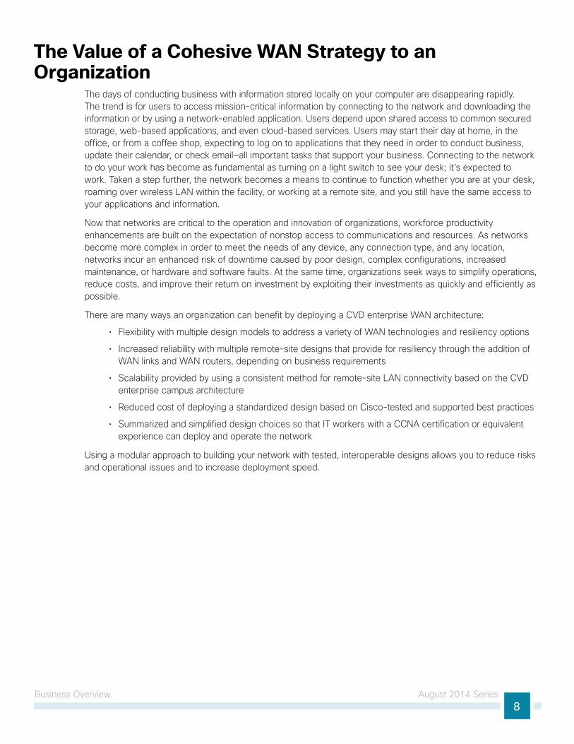
The Value of a Cohesive WAN Strategy to an Organization
The days of conducting business with information stored locally on your computer are disappearing rapidly. The trend is for users to access mission-critical information by connecting to the network and downloading the information or by using a network-enabled application. Users depend upon shared access to common secured storage, web-based applications, and even cloud-based services. Users may start their day at home, in the office, or from a coffee shop, expecting to log on to applications that they need in order to conduct business, update their calendar, or check email—all important tasks that support your business. Connecting to the network to do your work has become as fundamental as turning on a light switch to see your desk; it’s expected to work. Taken a step further, the network becomes a means to continue to function whether you are at your desk, roaming over wireless LAN within the facility, or working at a remote site, and you still have the same access to your applications and information.
Now that networks are critical to the operation and innovation of organizations, workforce productivity enhancements are built on the expectation of nonstop access to communications and resources. As networks become more complex in order to meet the needs of any device, any connection type, and any location, networks incur an enhanced risk of downtime caused by poor design, complex configurations, increased maintenance, or hardware and software faults. At the same time, organizations seek ways to simplify operations, reduce costs, and improve their return on investment by exploiting their investments as quickly and efficiently as possible.
There are many ways an organization can benefit by deploying a CVD enterprise WAN architecture:
• Flexibility with multiple design models to address a variety of WAN technologies and resiliency options
• Increased reliability with multiple remote-site designs that provide for resiliency through the addition of WAN links and WAN routers, depending on business requirements
• Scalability provided by using a consistent method for remote-site LAN connectivity based on the CVD enterprise campus architecture
• Reduced cost of deploying a standardized design based on Cisco-tested and supported best practices
• Summarized and simplified design choices so that IT workers with a CCNA certification or equivalent experience can deploy and operate the network
Using a modular approach to building your network with tested, interoperable designs allows you to reduce risks and operational issues and to increase deployment speed.
WAN Architecture August 2014 Series9
WAN Architecture There is a tendency to discount the network as just simple plumbing, to think that all you have to consider is the size and the length of the pipes or the speeds and feeds of the links, and to dismiss the rest as unimportant. Just as the plumbing in a large stadium or high rise has to be designed for scale, purpose, redundancy, protection from tampering or denial of operation, and the capacity to handle peak loads, the network requires similar consideration. As users depend on the network to access the majority of the information they need in order to do their jobs and to transport their voice or video with reliability, the network must be able to provide resilient, intelligent transport.
Many businesses have remote locations that depend entirely on applications hosted in a centralized data center. If a WAN outage occurs, these remote locations are essentially offline and they are unable to process transactions or support other types of business services. It is critical to provide reliable connectivity to these locations.
The demand for WAN bandwidth continues to increase, and there has been a recent trend towards using Ethernet as the WAN access media in order to deliver higher bandwidth. Even with the increased amount of bandwidth available to connect remote sites today, there are performance-sensitive applications affected by jitter, delay, and packet loss. It is the function of the network foundation to provide an efficient, fault-tolerant transport that can differentiate application traffic to make intelligent load-sharing decisions when the network is temporarily congested. Regardless of the chosen WAN technology, the network must provide intelligent prioritization and queuing of traffic along the most efficient route possible.
The CVD enterprise WAN design uses a variety of WAN transport technologies for primary links and backup links:
• MPLS WAN using Layer 3 VPN
• Layer 2 WAN using Virtual Private LAN Services (VPLS) or Metro Ethernet
• Internet with VPN WAN
• Dynamic Multipoint VPN
• Internet 3G/4G with VPN WAN
This guide provides a high level overview of each technology, followed by a discussion of the usage of each technology at the WAN-aggregation site and remote sites. This guide should also be used as a roadmap on how to use the companion WAN deployment guides.
WAN Transport TechnologiesMPLS WAN using Layer 3 VPN
Cisco IOS software MPLS enables organizations and service providers to build next-generation intelligent networks that deliver a wide variety of advanced, value-added services like QoS and service level agreements (SLAs) over a single infrastructure. You can integrate this economical solution seamlessly over any existing infrastructure, such as IP, Frame Relay, ATM, or Ethernet.
MPLS Layer 3 VPNs use a peer-to-peer VPN model that leverages BGP to distribute VPN-related information. This peer-to-peer model allows a customer to outsource routing information to service providers, which can result in significant cost savings and a reduction in operational complexity for organizations.
Subscribers who need to transport IP multicast traffic can enable Multicast VPNs (MVPNs).
WAN Architecture August 2014 Series10
Layer 2 WAN using Virtual Private LAN Services (VPLS) or Metro EthernetEthernet has traditionally been a LAN technology primarily due to the distance limitations of the available media and the requirement for dedicated copper or fiber links.
Layer 2 WAN transports are now widely available from service providers and are able to extend various Layer 2 traffic types (Frame Relay, Point-to-Point Protocol (PPP), ATM, or Ethernet) over a WAN. The most common implementations of Layer 2 WAN are used to provide Ethernet over the WAN using either a point-to-point or point-to-multipoint service.
Service providers implement these Ethernet services using a variety of methods. MPLS networks support both Ethernet over MPLS (EoMPLS) and VPLS. The providers use other network technologies, such as Ethernet switches in various topologies, to provide Ethernet Layer 2 WAN services. These offerings are also referred to as Carrier Ethernet or Metro Ethernet, and they are typically limited to a relatively small geographic area.
Layer 2 WAN supports a subscriber model in which the service provider is transparent and the organization implements all Layer 3 routing. This allows for flexibility in the WAN design and interconnection of the remote sites.
Point-to-point service allows for the interconnection of two LANs. Point-to-multipoint transparent LAN service allows for the interconnection of more than two LANs. Other service variants include simple and trunked demarcations. By using trunk mode, you can interconnect LANs using 802.1Q VLAN–tagging in order to provide transport of multiple VLANs on a single access trunk. Service providers often refer to a trunked service as Q-in-Q tunneling (QinQ).
Layer 2 WAN transport is transparent to the traffic type; therefore IP multicast traffic is supported with no additional configuration required by the service provider.
Internet with VPN WANThe Internet is essentially a large-scale public WAN composed of multiple interconnected service providers. The Internet can provide reliable high-performance connectivity between various locations, although it lacks any explicit guarantees for these connections. Despite its “best effort” nature, the Internet is a reasonable choice for a primary transport when it is not feasible to connect with another transport option. Additional resiliency for primary WAN transports like MPLS or Layer 2 WAN is provided by using the Internet as an alternate transport option.
Internet connections are typically included in discussions relevant to the Internet edge, specifically for the primary site. Remote-site routers also commonly have Internet connections, but do not provide the same breadth of services when using the Internet. For security and other reasons, Internet access at remote sites is often routed through the primary site. This summary also discusses local Internet access from a remote site.
Dynamic Multipoint VPNDynamic Multipoint VPN (DMVPN) is a solution for building scalable site-to-site VPNs that support a variety of applications. DMVPN is widely used for encrypted site-to-site connectivity over public or private IP networks and can be implemented on all WAN routers used in the CVD enterprise WAN design.
DMVPN was selected for the encryption solution for the Internet transport because it supports on-demand full mesh connectivity with a simple hub-and-spoke configuration and a zero-touch hub deployment model for adding remote sites. DMVPN also supports spoke routers that have dynamically assigned IP addresses.
DMVPN makes use of multipoint generic routing encapsulation (mGRE) tunnels to interconnect the hub to all of the spoke routers. These mGRE tunnels are also sometimes referred to as DMVPN clouds in this context. This technology combination supports unicast, multicast, and broadcast IP, including the ability to run routing protocols within the tunnels.
WAN Architecture August 2014 Series11
Internet 3G/4G with VPN WANCellular connectivity enables the use of Internet WAN, without requiring any wired infrastructure or circuits and provides a flexible, high-speed, high-bandwidth option. There are several 3G and higher-speed 4G technologies that are supported.
Remote Site using Local Internet AccessAlthough many of the applications and services that the remote-site worker uses are centrally located, there are benefits in providing local Internet access at each remote site location. Offloading Internet browsing and providing direct access to public cloud service providers can greatly reduce traffic on the private WAN, saving costs and improving overall survivability. Leveraging the cloud in the remote office can greatly increase performance and the overall cloud experience.
WAN Transport Technology SummaryThe CVD enterprise WAN design allows for the use of any and all of the listed WAN transport technologies, which enables the network architect to choose the most appropriate technology based on their business requirements. In some cases, service providers are limited in their coverage, or there is a large cost differential between technologies—CVD enterprise WAN allows the flexibility to consider multiple options. The primary benefit is that decisions can be made based on what is important to the organization.
Quality of ServiceMost users perceive the network as a transport utility mechanism to shift data from point A to point B as fast as it can. Many sum this up as just “speeds and feeds.” While it is true that IP networks forward traffic on a best-effort basis by default, this type of routing works well only for applications that adapt gracefully to variations in latency, jitter, and loss. However, networks are multiservice by design and support real-time voice and video as well as data traffic. The difference is that real-time applications require packets to be delivered within specified loss, delay, and jitter parameters.
In reality, the network affects all traffic flows and must be aware of end-user requirements and services being offered. Even with unlimited bandwidth, time-sensitive applications are affected by jitter, delay, and packet loss. QoS enables a multitude of user services and applications to coexist on the same network.
Within the architecture, there are wired and wireless connectivity options that provide advanced classification, prioritizing, queuing, and congestion mechanisms as part of the integrated QoS to help ensure optimal use of network resources. This functionality allows for the differentiation of applications, ensuring that each has the appropriate share of the network resources to protect the user experience and ensure the consistent operations of business critical applications.
QoS is an essential function of the network infrastructure devices used throughout this architecture. QoS enables a multitude of user services and applications, including real-time voice, high-quality video, and delay-sensitive data to coexist on the same network. In order for the network to provide predictable, measurable, and sometimes guaranteed services, it must manage bandwidth, delay, jitter, and loss parameters. Even if you do not require QoS for your current applications, you can use QoS for management and network protocols in order to protect the network functionality and manageability under normal and congested traffic conditions.
The goal of this design is to provide sufficient classes of service to allow you to add voice, interactive video, critical data applications, and management traffic to the network, either during the initial deployment or later with minimal system impact and engineering effort.
WAN Architecture August 2014 Series12
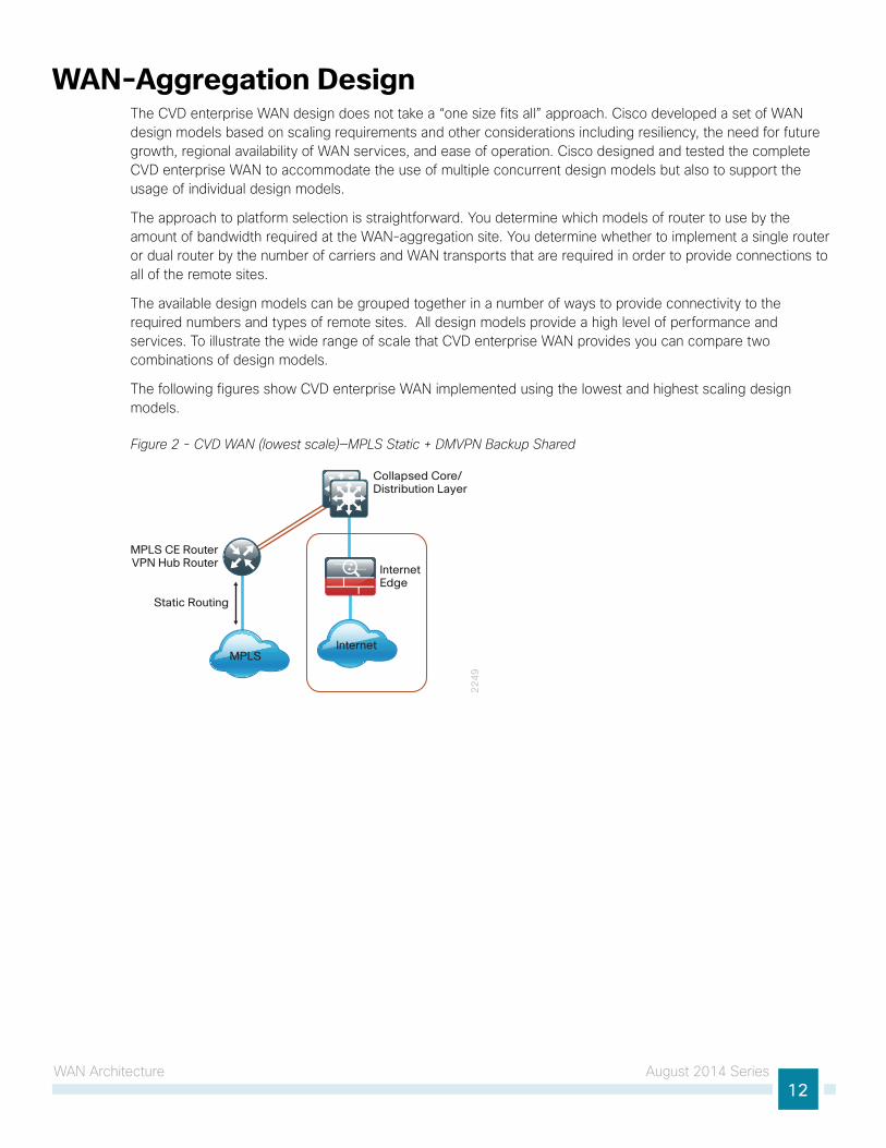
WAN-Aggregation Design The CVD enterprise WAN design does not take a “one size fits all” approach. Cisco developed a set of WAN design models based on scaling requirements and other considerations including resiliency, the need for future growth, regional availability of WAN services, and ease of operation. Cisco designed and tested the complete CVD enterprise WAN to accommodate the use of multiple concurrent design models but also to support the usage of individual design models.
The approach to platform selection is straightforward. You determine which models of router to use by the amount of bandwidth required at the WAN-aggregation site. You determine whether to implement a single router or dual router by the number of carriers and WAN transports that are required in order to provide connections to all of the remote sites.
The available design models can be grouped together in a number of ways to provide connectivity to the required numbers and types of remote sites. All design models provide a high level of performance and services. To illustrate the wide range of scale that CVD enterprise WAN provides you can compare two combinations of design models.
The following figures show CVD enterprise WAN implemented using the lowest and highest scaling design models.
Figure 2 - CVD WAN (lowest scale)—MPLS Static + DMVPN Backup Shared
22
49
InternetEdge
MPLS
MPLS CE RouterVPN Hub Router
Collapsed Core/Distribution Layer
Static Routing
Internet

WAN Architecture August 2014 Series13
Figure 3 - CVD WAN (highest scale)—Dual MPLS + Layer 2 Trunked + Dual DMVPN
Internet Edge
VPN HubRouters
Layer 2 WANCE Router
TrunkedDemarcation
Core Layer
Distribution Layer
MPLS CERouters
22
50
BGP DynamicRouting
MPLS A Layer 2MPLS B
Internet A Internet B
WAN Remote-Site DesignThis guide documents multiple WAN remote-site designs, and they are based on various combinations of WAN transports mapped to the site-specific requirements for service levels and redundancy.
Most remote sites are designed with a single-router WAN edge; however, certain remote-site types require a dual-router WAN edge. Dual-router candidate sites include regional office or remote campus locations with large user populations, or sites with business critical needs that justify additional redundancy to remove single points of failure. Similarly, the size of the remote-site LAN depends on factors such as number of connected users and the physical layout of the remote site.
The actual WAN remote-site routing platforms remain unspecified because the specification is tied closely to the bandwidth required for a location and the potential requirement for the use of service module slots. The ability to implement this solution with a variety of potential router choices is one of the benefits of a modular design approach.
There are many factors to consider in the selection of the WAN remote-site routers. Among those, and key to the initial deployment, is the ability to process the expected amount and type of traffic. You also need to make sure that you have enough interfaces, enough module slots, and a properly licensed Cisco IOS Software image that supports the set of features that is required by the topology.
WAN Architecture August 2014 Series14
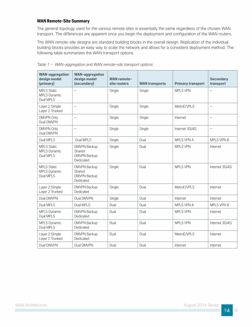
WAN Remote-Site SummaryThe general topology used for the various remote sites is essentially the same regardless of the chosen WAN transport. The differences are apparent once you begin the deployment and configuration of the WAN routers.
The WAN remote-site designs are standard building blocks in the overall design. Replication of the individual building blocks provides an easy way to scale the network and allows for a consistent deployment method. The following table summarizes the WAN transport options.
Table 1 - WAN-aggregation and WAN remote-site transport options
WAN-aggregation design model (primary)
WAN-aggregation design model (secondary)
WAN remote- site routers WAN transports Primary transport
Secondary transport
MPLS Static MPLS Dynamic Dual MPLS
— Single Single MPLS VPN —
Layer 2 Simple Layer 2 Trunked
— Single Single MetroE/VPLS —
DMVPN Only Dual DMVPN
— Single Single Internet —
DMVPN Only Dual DMVPN
— Single Single Internet 3G/4G —
Dual MPLS Dual MPLS Single Dual MPLS VPN A MPLS VPN B
MPLS Static MPLS Dynamic Dual MPLS
DMVPN Backup Shared DMVPN Backup Dedicated
Single Dual MPLS VPN Internet
MPLS Static MPLS Dynamic Dual MPLS
DMVPN Backup Shared DMVPN Backup Dedicated
Single Dual MPLS VPN Internet 3G/4G
Layer 2 Simple Layer 2 Trunked
DMVPN Backup Dedicated
Single Dual MetroE/VPLS Internet
Dual DMVPN Dual DMVPN Single Dual Internet Internet
Dual MPLS Dual MPLS Dual Dual MPLS VPN A MPLS VPN B
MPLS Dynamic Dual MPLS
DMVPN Backup Dedicated
Dual Dual MPLS VPN Internet
MPLS Dynamic Dual MPLS
DMVPN Backup Dedicated
Dual Dual MPLS VPN Internet 3G/4G
Layer 2 Simple Layer 2 Trunked
DMVPN Backup Dedicated
Dual Dual MetroE/VPLS Internet
Dual DMVPN Dual DMVPN Dual Dual Internet Internet
WAN Architecture August 2014 Series15
MPLS WANThis section covers the following three WAN-aggregation design models:
• MPLS Static
• MPLS Dynamic
• Dual MPLS
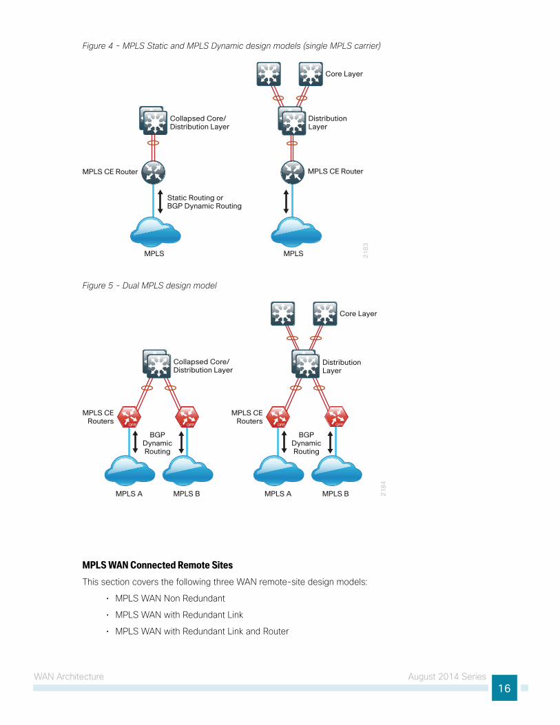
The MPLS WAN-aggregation (hub) designs include one or two WAN edge routers. When WAN edge routers are referred to in the context of the connection to a carrier or service provider, they are typically known as CE routers. All of the WAN edge routers connect into a LAN distribution layer.
The WAN transport options include MPLS VPN used as a primary or secondary transport. Each transport connects to a dedicated CE router. You use a similar method of connection and configuration for both.
This design documents three MPLS WAN-aggregation design models that are statically or dynamically routed with either single or dual MPLS carriers. The primary differences between the various designs are the usage of routing protocols and the overall scale of the architecture. For each design model, you can select several router platforms with differing levels of performance and resiliency capabilities.
Each of the design models uses LAN connections into either a collapsed core/distribution layer or a dedicated WAN distribution layer. There are no functional differences between these two methods from the WAN-aggregation perspective.
In all of the WAN-aggregation designs, tasks such as IP route summarization are performed at the distribution layer. There are other various devices supporting WAN edge services such as application optimization and encryption, and these devices should also connect into the distribution layer.
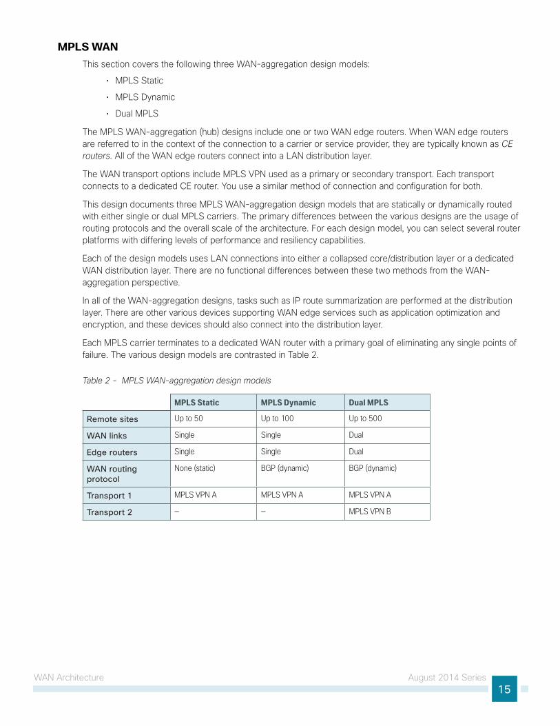
Each MPLS carrier terminates to a dedicated WAN router with a primary goal of eliminating any single points of failure. The various design models are contrasted in Table 2.
Table 2 - MPLS WAN-aggregation design models
MPLS Static MPLS Dynamic Dual MPLS
Remote sites Up to 50 Up to 100 Up to 500
WAN links Single Single Dual
Edge routers Single Single Dual
WAN routing protocol
None (static) BGP (dynamic) BGP (dynamic)
Transport 1 MPLS VPN A MPLS VPN A MPLS VPN A
Transport 2 — — MPLS VPN B
WAN Architecture August 2014 Series16
Figure 4 - MPLS Static and MPLS Dynamic design models (single MPLS carrier)
21
83
MPLS
MPLS CE Router MPLS CE Router
Static Routing orBGP Dynamic Routing
Collapsed Core/Distribution Layer
MPLS
Core Layer
DistributionLayer
Figure 5 - Dual MPLS design model
21
84
MPLS CERouters
BGPDynamicRouting
MPLS A MPLS B
MPLS CERouters
BGPDynamicRouting
MPLS A MPLS B
Collapsed Core/Distribution Layer
DistributionLayer
Core Layer
MPLS WAN Connected Remote SitesThis section covers the following three WAN remote-site design models:
• MPLS WAN Non Redundant
• MPLS WAN with Redundant Link
• MPLS WAN with Redundant Link and Router
WAN Architecture August 2014 Series17
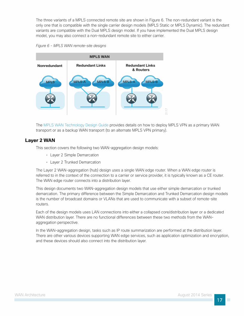
The three variants of a MPLS connected remote site are shown in Figure 6. The non-redundant variant is the only one that is compatible with the single carrier design models (MPLS Static or MPLS Dynamic). The redundant variants are compatible with the Dual MPLS design model. If you have implemented the Dual MPLS design model, you may also connect a non-redundant remote site to either carrier.
Figure 6 - MPLS WAN remote-site designs
21
17
Redundant Links Redundant Links & Routers
Nonredundant
MPLS WAN
MPLS MPLS-A MPLS-B MPLS-A MPLS-B
The MPLS WAN Technology Design Guide provides details on how to deploy MPLS VPN as a primary WAN transport or as a backup WAN transport (to an alternate MPLS VPN primary).
Layer 2 WANThis section covers the following two WAN-aggregation design models:
• Layer 2 Simple Demarcation
• Layer 2 Trunked Demarcation
The Layer 2 WAN-aggregation (hub) design uses a single WAN edge router. When a WAN edge router is referred to in the context of the connection to a carrier or service provider, it is typically known as a CE router. The WAN edge router connects into a distribution layer.
This design documents two WAN-aggregation design models that use either simple demarcation or trunked demarcation. The primary difference between the Simple Demarcation and Trunked Demarcation design models is the number of broadcast domains or VLANs that are used to communicate with a subset of remote-site routers.
Each of the design models uses LAN connections into either a collapsed core/distribution layer or a dedicated WAN distribution layer. There are no functional differences between these two methods from the WAN-aggregation perspective.
In the WAN-aggregation design, tasks such as IP route summarization are performed at the distribution layer. There are other various devices supporting WAN edge services, such as application optimization and encryption, and these devices should also connect into the distribution layer.
WAN Architecture August 2014 Series18
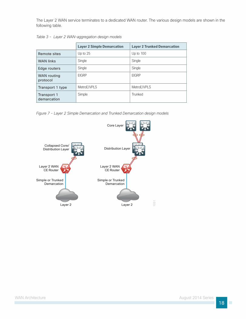
The Layer 2 WAN service terminates to a dedicated WAN router. The various design models are shown in the following table.
Table 3 - Layer 2 WAN-aggregation design models
Layer 2 Simple Demarcation Layer 2 Trunked Demarcation
Remote sites Up to 25 Up to 100
WAN links Single Single
Edge routers Single Single
WAN routing protocol
EIGRP EIGRP
Transport 1 type MetroE/VPLS MetroE/VPLS
Transport 1 demarcation
Simple Trunked
Figure 7 - Layer 2 Simple Demarcation and Trunked Demarcation design models
10
31
Layer 2
Layer 2 WANCE Router
Simple or TrunkedDemarcation
Collapsed Core/Distribution Layer
Layer 2
Layer 2 WANCE Router
Simple or TrunkedDemarcation
Distribution Layer
Core Layer
WAN Architecture August 2014 Series19
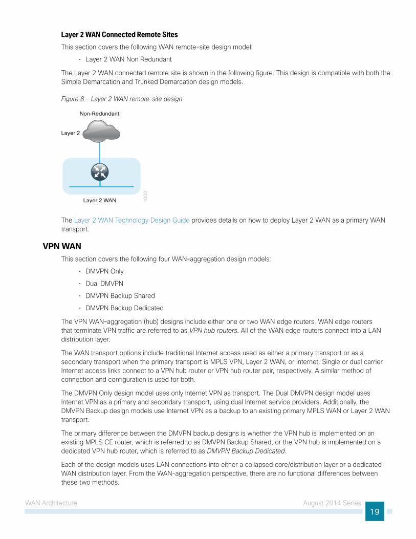
Layer 2 WAN Connected Remote SitesThis section covers the following WAN remote-site design model:
• Layer 2 WAN Non Redundant
The Layer 2 WAN connected remote site is shown in the following figure. This design is compatible with both the Simple Demarcation and Trunked Demarcation design models.
Figure 8 - Layer 2 WAN remote-site design
10
33
Non-Redundant
Layer 2
Layer 2 WAN
The Layer 2 WAN Technology Design Guide provides details on how to deploy Layer 2 WAN as a primary WAN transport.
VPN WAN This section covers the following four WAN-aggregation design models:
• DMVPN Only
• Dual DMVPN
• DMVPN Backup Shared
• DMVPN Backup Dedicated
The VPN WAN-aggregation (hub) designs include either one or two WAN edge routers. WAN edge routers that terminate VPN traffic are referred to as VPN hub routers. All of the WAN edge routers connect into a LAN distribution layer.
The WAN transport options include traditional Internet access used as either a primary transport or as a secondary transport when the primary transport is MPLS VPN, Layer 2 WAN, or Internet. Single or dual carrier Internet access links connect to a VPN hub router or VPN hub router pair, respectively. A similar method of connection and configuration is used for both.
The DMVPN Only design model uses only Internet VPN as transport. The Dual DMVPN design model uses Internet VPN as a primary and secondary transport, using dual Internet service providers. Additionally, the DMVPN Backup design models use Internet VPN as a backup to an existing primary MPLS WAN or Layer 2 WAN transport.
The primary difference between the DMVPN backup designs is whether the VPN hub is implemented on an existing MPLS CE router, which is referred to as DMVPN Backup Shared, or the VPN hub is implemented on a dedicated VPN hub router, which is referred to as DMVPN Backup Dedicated.
Each of the design models uses LAN connections into either a collapsed core/distribution layer or a dedicated WAN distribution layer. From the WAN-aggregation perspective, there are no functional differences between these two methods.
WAN Architecture August 2014 Series20
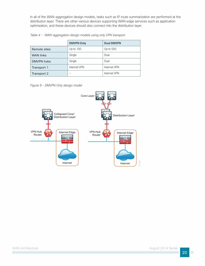
In all of the WAN-aggregation design models, tasks such as IP route summarization are performed at the distribution layer. There are other various devices supporting WAN edge services such as application optimization, and these devices should also connect into the distribution layer.
Table 4 - WAN-aggregation design models using only VPN transport
DMVPN Only Dual DMVPN
Remote sites Up to 100 Up to 500
WAN links Single Dual
DMVPN hubs Single Dual
Transport 1 Internet VPN Internet VPN
Transport 2 — Internet VPN
Figure 9 - DMVPN Only design model
21
33
VPN HubRouter
Core Layer
Internet
Internet Edge
Collapsed Core/Distribution Layer
VPN HubRouter
Internet
Internet Edge
Distribution Layer
WAN Architecture August 2014 Series21
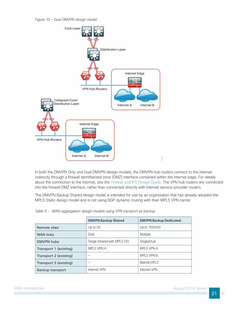
Figure 10 - Dual DMVPN design model
21
34
Core Layer
Collapsed Core/Distribution Layer
Internet Edge
Internet A Internet B
Distribution Layer
Internet Edge
Internet A Internet B
VPN Hub Routers
VPN Hub Routers
In both the DMVPN Only and Dual DMVPN design models, the DMVPN hub routers connect to the Internet indirectly through a firewall demilitarized zone (DMZ) interface contained within the Internet edge. For details about the connection to the Internet, see the Firewall and IPS Design Guide. The VPN hub routers are connected into the firewall DMZ interface, rather than connected directly with Internet service-provider routers.
The DMVPN Backup Shared design model is intended for use by an organization that has already adopted the MPLS Static design model and is not using BGP dynamic routing with their MPLS VPN carrier.
Table 5 - WAN-aggregation design models using VPN transport as backup
DMVPN Backup Shared DMVPN Backup Dedicated
Remote sites Up to 50 Up to 100/500
WAN links Dual Multiple
DMVPN hubs Single (shared with MPLS CE) Single/Dual
Transport 1 (existing) MPLS VPN A MPLS VPN A
Transport 2 (existing) — MPLS VPN B
Transport 3 (existing) — MetroE/VPLS
Backup transport Internet VPN Internet VPN
WAN Architecture August 2014 Series22
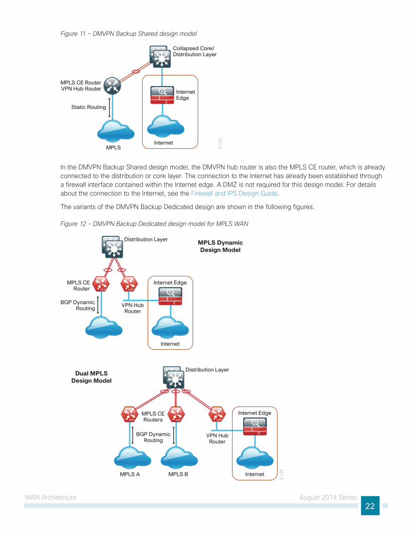
Figure 11 - DMVPN Backup Shared design model
21
35
Internet
InternetEdge
MPLS
MPLS CE RouterVPN Hub Router
Collapsed Core/Distribution Layer
Static Routing
In the DMVPN Backup Shared design model, the DMVPN hub router is also the MPLS CE router, which is already connected to the distribution or core layer. The connection to the Internet has already been established through a firewall interface contained within the Internet edge. A DMZ is not required for this design model. For details about the connection to the Internet, see the Firewall and IPS Design Guide.
The variants of the DMVPN Backup Dedicated design are shown in the following figures.
Figure 12 - DMVPN Backup Dedicated design model for MPLS WAN
21
36
MPLS CERouters
VPN HubRouter
Internet
Internet Edge
Distribution Layer
MPLS BMPLS A
MPLS CERouter
VPN HubRouter
Internet
Internet Edge
Distribution Layer
BGP DynamicRouting
BGP DynamicRouting
MPLS DynamicDesign Model
Dual MPLSDesign Model

WAN Architecture August 2014 Series23
Figure 13 - DMVPN Backup Dedicated design model for Layer 2 WAN primary
VPN HubRouter
21
37
Layer 2 WANCE Router
Layer 2 Internet
Internet Edge
Distribution Layer
Simple or TrunkedDemarcation
In the DMVPN Backup Dedicated design models, the DMVPN hub routers connect to the Internet indirectly through a firewall DMZ interface contained within the Internet edge. For details about the connection to the Internet, see the Firewall and IPS Design Guide. The VPN hub routers are connected into the firewall DMZ interface, rather than connected directly with Internet service-provider routers.
Note that the DMVPN Only and Dual DMVPN design models can also provide DMVPN backup when paired with MPLS WAN and Layer 2 WAN design models.
VPN WAN Connected Remote SitesThis section covers the following seven WAN remote-site design models:
• VPN WAN Non Redundant
• VPN WAN with Redundant Link
• VPN WAN with Redundant Link and Router
• MPLS WAN with VPN WAN Redundant Link
• MPLS WAN with VPN WAN Redundant Link and Router
• Layer 2 WAN with VPN WAN Redundant Link
• Layer 2 WAN with VPN WAN Redundant Link and Router
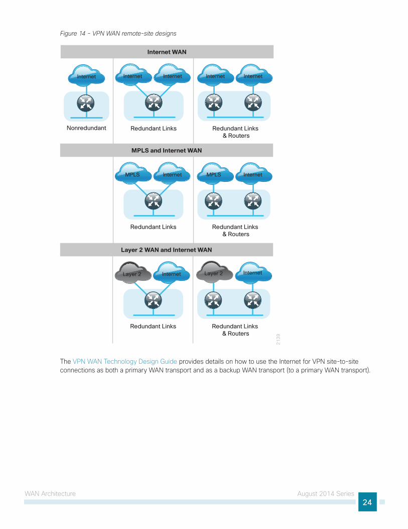
The multiple variants of a VPN WAN connected remote site are shown in Figure 14. The Internet WAN non-redundant variant is compatible with the DMVPN Only and Dual DMVPN design models. Both of the Internet WAN redundant link variants are compatible with the Dual DMVPN design model.
The MPLS + Internet WAN single router (redundant links) variant is compatible with either the DMVPN Backup Dedicated or DMVPN Backup Shared design models. The MPLS + Internet WAN dual router (redundant links and routers) and both Layer 2 WAN + Internet WAN variants are compatible with the DMVPN Backup Dedicated design model.
WAN Architecture August 2014 Series24
Figure 14 - VPN WAN remote-site designs
21
39
Redundant Links Redundant Links & Routers
Nonredundant
Internet Internet Internet Internet Internet
Internet WAN
Redundant Links Redundant Links & Routers
MPLS Internet MPLS Internet
MPLS and Internet WAN
Redundant Links Redundant Links & Routers
Internet Internet
Layer 2 WAN and Internet WAN
Layer 2 Layer 2
The VPN WAN Technology Design Guide provides details on how to use the Internet for VPN site-to-site connections as both a primary WAN transport and as a backup WAN transport (to a primary WAN transport).
WAN Architecture August 2014 Series25
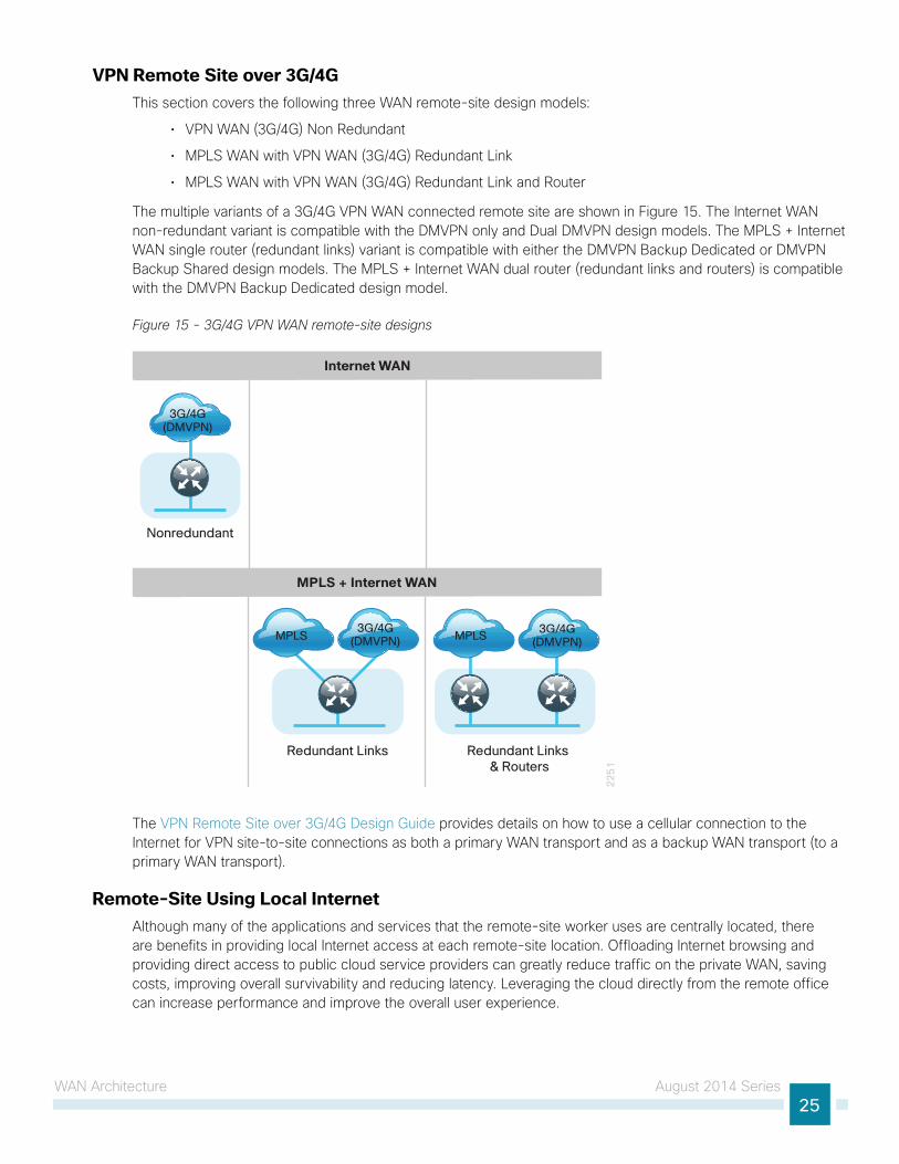
VPN Remote Site over 3G/4GThis section covers the following three WAN remote-site design models:
• VPN WAN (3G/4G) Non Redundant
• MPLS WAN with VPN WAN (3G/4G) Redundant Link
• MPLS WAN with VPN WAN (3G/4G) Redundant Link and Router
The multiple variants of a 3G/4G VPN WAN connected remote site are shown in Figure 15. The Internet WAN non-redundant variant is compatible with the DMVPN only and Dual DMVPN design models. The MPLS + Internet WAN single router (redundant links) variant is compatible with either the DMVPN Backup Dedicated or DMVPN Backup Shared design models. The MPLS + Internet WAN dual router (redundant links and routers) is compatible with the DMVPN Backup Dedicated design model.
Figure 15 - 3G/4G VPN WAN remote-site designs
22
51
Nonredundant
Internet WAN
Redundant Links Redundant Links & Routers
MPLS MPLS
MPLS + Internet WAN
3G/4G(DMVPN)
3G/4G(DMVPN)
3G/4G(DMVPN)
The VPN Remote Site over 3G/4G Design Guide provides details on how to use a cellular connection to the Internet for VPN site-to-site connections as both a primary WAN transport and as a backup WAN transport (to a primary WAN transport).
Remote-Site Using Local InternetAlthough many of the applications and services that the remote-site worker uses are centrally located, there are benefits in providing local Internet access at each remote-site location. Offloading Internet browsing and providing direct access to public cloud service providers can greatly reduce traffic on the private WAN, saving costs, improving overall survivability and reducing latency. Leveraging the cloud directly from the remote office can increase performance and improve the overall user experience.

WAN Architecture August 2014 Series26
Figure 16 - Single-router, single-link remote site with local Internet access
11
16
Router withFirewall
InternetDMVPN
The following table summarizes the WAN transport options for remote sites using local Internet. This is a subset of the transport options listed previously, and it is important to note that the remote site routing configuration changes when local Internet access is deployed.
Table 6 - WAN-aggregation and WAN remote-site transport options with local Internet
WAN-Aggregation design model (primary)
WAN-Aggregation design model (secondary)
WAN remote- site routers WAN transports Primary transport
Secondary transport
DMVPN Only Dual DMVPN
— Single Single Internet —
DMVPN Only Dual DMVPN
— Single Single Internet 3G/4G —
MPLS Static MPLS Dynamic Dual MPLS
DMVPN Backup Shared DMVPN Backup Dedicated
Single Dual MPLS VPN Internet
MPLS Static MPLS Dynamic Dual MPLS
DMVPN Backup Shared DMVPN Backup Dedicated
Single Dual MPLS VPN Internet 3G/4G
Layer 2 Simple Layer 2 Trunked
DMVPN Backup Dedicated
Single Dual MetroE/VPLS Internet
Dual DMVPN Dual DMVPN Single Dual Internet Internet
MPLS Dynamic Dual MPLS
DMVPN Backup Dedicated
Dual Dual MPLS VPN Internet
MPLS Dynamic Dual MPLS
DMVPN Backup Dedicated
Dual Dual MPLS VPN Internet 3G/4G
Layer 2 Simple Layer 2 Trunked
DMVPN Backup Dedicated
Dual Dual MetroE/VPLS Internet
Dual DMVPN Dual DMVPN Dual Dual Internet Internet

WAN Architecture August 2014 Series27
Local Internet Design ModelsCloud-enabled, remote-site designs provide remote-office local Internet access solutions for web browsing and cloud services. This is referred to as the local Internet access model. With this model, user web traffic and hosted cloud services traffic is permitted to use the local Internet link in a split-tunneling manner. In this model, a default route is generated locally from each remote site directly to the Internet provider. Private WAN connections using DMVPN over Internet, MPLS, or L2 WAN provide internal routes to the data center and campus. In some configurations backup Internet routing is provided over the private WAN connections.
Figure 17 - Central Internet and local Internet comparison
InternetPrimary WAN
(no central site)
DMVPN Backup(no central site)
11
17
InternetAccess
VPN TunnelTraffic Only
Central Internet(aka Central-Tunneling)
InternetPrimary WAN
(no central site)
DMVPN Backup(no central site)
InternalResources
Only
Internet Access and VPN TunnelTraffic
Local Internet(aka Split-Tunneling)
The primary focus of the design is to allow usage of the following commonly deployed remote-site WAN configurations with local Internet access:
• Single router remote site with Internet and DMVPN WAN connectivity
• Single or dual router remote site with MPLS WAN and local Internet using DMVPN for backup
• Single or dual router remote site with both L2 WAN and local Internet using DMVPN for backup
• Single or dual router remote site with dual-Internet DMVPN for primary and backup connectivity

WAN Architecture August 2014 Series28
Figure 18 - Single router, remote-site design models
11
18
MPLSVPN A
InternetDMVPN-1
Single Router WAN Options with Local Internet Access
InternetDMVPN-1
InternetDMVPN-2
InternetDMVPN-1
InternetDMVPN-1L2 WAN
Figure 19 - Dual router, remote-site design models
11
19
MPLSVPN A
Dual Router DMVPN Backup Options with Local Internet
InternetDMVPN-1
InternetDMVPN-2
InternetDMVPN-1
InternetDMVPN-1L2 WAN
For information about how to deploy this WAN service, see the Remote Site Using Local Internet Access Technology Design Guide.
WAN Architecture August 2014 Series29
Remote-Site Wired LAN The primary role of the WAN is to interconnect primary site and remote-site LANs. The LAN discussion within this guide is limited to how the remote-site LANs connect to the remote-site WAN devices.
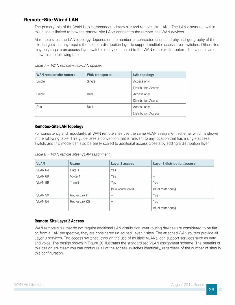
At remote sites, the LAN topology depends on the number of connected users and physical geography of the site. Large sites may require the use of a distribution layer to support multiple access layer switches. Other sites may only require an access layer switch directly connected to the WAN remote-site routers. The variants are shown in the following table.
Table 7 - WAN remote-sites—LAN options
WAN remote-site routers WAN transports LAN topology
Single Single Access only
Distribution/Access
Single Dual Access only
Distribution/Access
Dual Dual Access only
Distribution/Access
Remotes-Site LAN TopologyFor consistency and modularity, all WAN remote sites use the same VLAN assignment scheme, which is shown in the following table. This guide uses a convention that is relevant to any location that has a single access switch, and this model can also be easily scaled to additional access closets by adding a distribution layer.
Table 8 - WAN remote sites—VLAN assignment
VLAN Usage Layer 2 access Layer 3 distribution/access
VLAN 64 Data 1 Yes —
VLAN 69 Voice 1 Yes —
VLAN 99 Transit Yes
(dual router only)
Yes
(dual router only)
VLAN 50 Router Link (1) — Yes
VLAN 54 Router Link (2) — Yes
(dual router only)
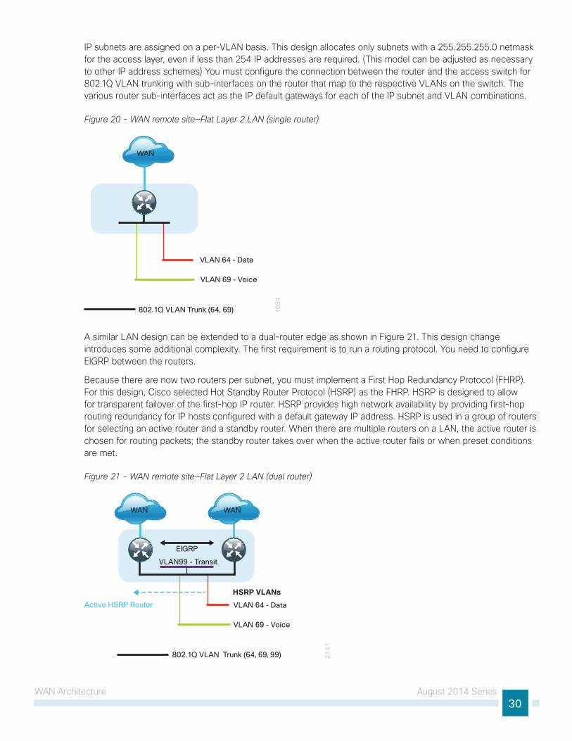
Remote-Site Layer 2 AccessWAN remote sites that do not require additional LAN distribution layer routing devices are considered to be flat or, from a LAN perspective, they are considered un-routed Layer 2 sites. The attached WAN routers provide all Layer 3 services. The access switches, through the use of multiple VLANs, can support services such as data and voice. The design shown in Figure 20 illustrates the standardized VLAN assignment scheme. The benefits of this design are clear: you can configure all of the access switches identically, regardless of the number of sites in this configuration.
WAN Architecture August 2014 Series30
IP subnets are assigned on a per-VLAN basis. This design allocates only subnets with a 255.255.255.0 netmask for the access layer, even if less than 254 IP addresses are required. (This model can be adjusted as necessary to other IP address schemes) You must configure the connection between the router and the access switch for 802.1Q VLAN trunking with sub-interfaces on the router that map to the respective VLANs on the switch. The various router sub-interfaces act as the IP default gateways for each of the IP subnet and VLAN combinations.
Figure 20 - WAN remote site—Flat Layer 2 LAN (single router)
VLAN 64 - Data
802.1Q VLAN Trunk (64, 69)
VLAN 69 - Voice1
03
4
WAN
A similar LAN design can be extended to a dual-router edge as shown in Figure 21. This design change introduces some additional complexity. The first requirement is to run a routing protocol. You need to configure EIGRP between the routers.
Because there are now two routers per subnet, you must implement a First Hop Redundancy Protocol (FHRP). For this design, Cisco selected Hot Standby Router Protocol (HSRP) as the FHRP. HSRP is designed to allow for transparent failover of the first-hop IP router. HSRP provides high network availability by providing first-hop routing redundancy for IP hosts configured with a default gateway IP address. HSRP is used in a group of routers for selecting an active router and a standby router. When there are multiple routers on a LAN, the active router is chosen for routing packets; the standby router takes over when the active router fails or when preset conditions are met.
Figure 21 - WAN remote site—Flat Layer 2 LAN (dual router)
WAN WAN
Active HSRP Router VLAN 64 - Data
VLAN99 - Transit
802.1Q VLAN Trunk (64, 69, 99)
VLAN 69 - Voice
21
41
HSRP VLANs
EIGRP

WAN Architecture August 2014 Series31
Enhanced Object Tracking (EOT) provides a consistent methodology for various router and switching features to conditionally modify their operation based on information objects available within other processes. The objects that can be tracked include interface line protocol, IP route reachability, and IP service-level agreement (SLA) reachability as well as several others.
To improve convergence times after a primary WAN failure, HSRP has the capability to monitor the reachability of a next-hop IP neighbor through the use of EOT and IP SLA. This combination allows for a router to give up its HSRP active role if its upstream neighbor becomes unresponsive. This provides additional network resiliency.
Figure 22 - WAN remote site—IP SLA probe to verify upstream device reachability
WAN
Active HSRP Router
VLAN 64 - Data
VLAN 99 - Transit
802.1Q VLAN Trunk (64, 69, 99)
VLAN 69 - Voice 21
42HSRP VLANs
EIGRP
IP SLAProbe
WANInterface R1
UpstreamInterface
WAN
IP SLA Probeas Tracked Object
Detailed View
WAN
HSRP is configured to be active on the router with the highest priority WAN transport. EOT of IP SLA probes is implemented in conjunction with HSRP so that in the case of WAN transport failure, the standby HSRP router associated with the lower priority (alternate) WAN transport becomes the active HSRP router. The IP SLA probes are sent from the remote-site primary WAN router to the upstream neighbor (MPLS PE, Layer 2 WAN CE, or DMVPN hub) to ensure reachability of the next hop router. This is more effective than simply monitoring the status of the WAN interface.
The dual-router designs also warrant an additional transit network component that is required for proper routing in certain scenarios. In these cases, a traffic flow from a remote-site host might be sent to a destination reachable via the alternate WAN transport (for example, a dual MPLS remote site communicating with a MPLS-B-only remote site). The primary WAN transport router then forwards the traffic back out the same data interface on which it was received from the LAN to send it to the alternate WAN transport router, which then forwards the traffic to the proper destination. This is referred to as hairpinning.
The appropriate method to avoid sending the traffic out the same interface is to introduce an additional link between the routers and designate the link as a transit network (VLAN 99). There are no hosts connected to the transit network, and it is only used for router-router communication. The routing protocol runs between router sub-interfaces assigned to the transit network. No additional router interfaces are required with this design modification because the 802.1Q VLAN trunk configuration can easily accommodate an additional sub-interface.

WAN Architecture August 2014 Series32
Remote-Site Distribution and Access LayerLarge remote sites may require a LAN environment similar to that of a small campus LAN that includes a distribution layer and access layer. This topology works well with either a single- or dual-router WAN edge. To implement this design, the routers should connect via EtherChannel links to the distribution switch. These EtherChannel links are configured as 802.1Q VLAN trunks, to support both a routed point-to-point link to allow EIGRP routing with the distribution switch, and in the dual-router design, to provide a transit network for direct communication between the WAN routers.
Figure 23 - WAN remote site—Connection to distribution layer with single and dual routers
20
07
WAN WAN
802.1Q Trunk(50)
802.1Q Trunk (ww, xx) 802.1Q Trunk (yy, zz) 802.1Q Trunk (ww, xx)
802.1Q Trunk(50, 99)
802.1Q Trunk(54, 99)
VLAN 50 - Router 1 LinkVLAN 54 - Router 2 LinkVLAN 99 - Transit
VLAN 50 - Router 1 Link
802.1Q Trunk (yy, zz)
WAN Architecture August 2014 Series33
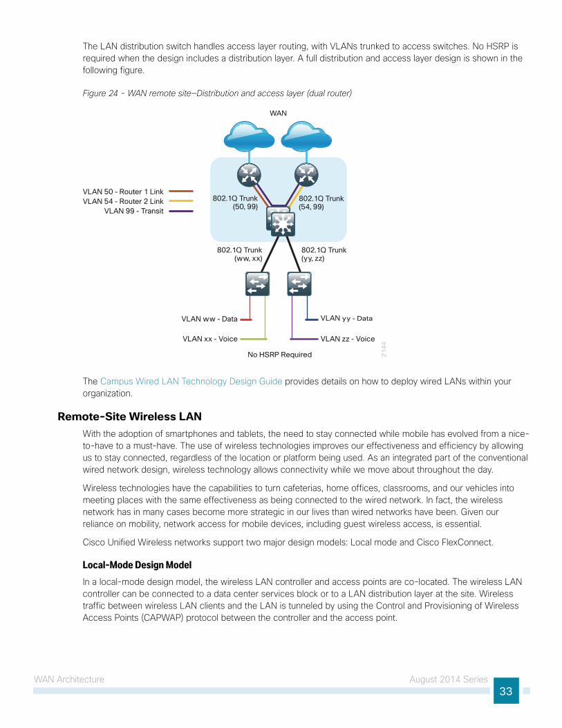
The LAN distribution switch handles access layer routing, with VLANs trunked to access switches. No HSRP is required when the design includes a distribution layer. A full distribution and access layer design is shown in the following figure.
Figure 24 - WAN remote site—Distribution and access layer (dual router)
21
44
WAN
VLAN 50 - Router 1 Link
802.1Q Trunk(ww, xx)
VLAN ww - Data
VLAN xx - Voice
VLAN yy - Data
VLAN zz - Voice
No HSRP Required
802.1Q Trunk(yy, zz)
802.1Q Trunk(50, 99)
802.1Q Trunk(54, 99)
VLAN 54 - Router 2 LinkVLAN 99 - Transit
The Campus Wired LAN Technology Design Guide provides details on how to deploy wired LANs within your organization.
Remote-Site Wireless LANWith the adoption of smartphones and tablets, the need to stay connected while mobile has evolved from a nice-to-have to a must-have. The use of wireless technologies improves our effectiveness and efficiency by allowing us to stay connected, regardless of the location or platform being used. As an integrated part of the conventional wired network design, wireless technology allows connectivity while we move about throughout the day.
Wireless technologies have the capabilities to turn cafeterias, home offices, classrooms, and our vehicles into meeting places with the same effectiveness as being connected to the wired network. In fact, the wireless network has in many cases become more strategic in our lives than wired networks have been. Given our reliance on mobility, network access for mobile devices, including guest wireless access, is essential.
Cisco Unified Wireless networks support two major design models: Local mode and Cisco FlexConnect.
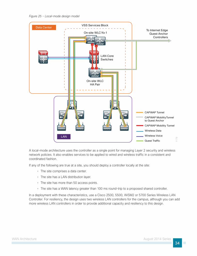
Local-Mode Design Model In a local-mode design model, the wireless LAN controller and access points are co-located. The wireless LAN controller can be connected to a data center services block or to a LAN distribution layer at the site. Wireless traffic between wireless LAN clients and the LAN is tunneled by using the Control and Provisioning of Wireless Access Points (CAPWAP) protocol between the controller and the access point.
WAN Architecture August 2014 Series34
Figure 25 - Local-mode design model
11
79LAN
VSS Services Block
On-site WLC N+1
LAN CoreSwitches
Data Center
On-site WLCHA Pair
To Internet EdgeGuest Anchor
Controllers
CAPWAP Tunnel
CAPWAP MobilityTunnel to Guest Anchor
CAPWAP Mobility Tunnel
Wireless Data
Wireless Voice
Guest Traffic
A local-mode architecture uses the controller as a single point for managing Layer 2 security and wireless network policies. It also enables services to be applied to wired and wireless traffic in a consistent and coordinated fashion.
If any of the following are true at a site, you should deploy a controller locally at the site:
• The site comprises a data center.
• The site has a LAN distribution layer.
• The site has more than 50 access points.
• The site has a WAN latency greater than 100 ms round-trip to a proposed shared controller.
In a deployment with these characteristics, use a Cisco 2500, 5500, WiSM2 or 5700 Series Wireless LAN Controller. For resiliency, the design uses two wireless LAN controllers for the campus, although you can add more wireless LAN controllers in order to provide additional capacity and resiliency to this design.
WAN Architecture August 2014 Series35
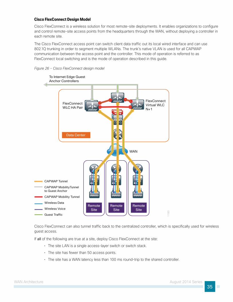
Cisco FlexConnect Design ModelCisco FlexConnect is a wireless solution for most remote-site deployments. It enables organizations to configure and control remote-site access points from the headquarters through the WAN, without deploying a controller in each remote site.
The Cisco FlexConnect access point can switch client data traffic out its local wired interface and can use 802.1Q trunking in order to segment multiple WLANs. The trunk’s native VLAN is used for all CAPWAP communication between the access point and the controller. This mode of operation is referred to as FlexConnect local switching and is the mode of operation described in this guide.
Figure 26 - Cisco FlexConnect design model
11
80
WAN
RemoteSite
RemoteSite
RemoteSite
FlexConnectWLC HA Pair
FlexConnectVirtual WLCN+1
Data Center
To Internet Edge GuestAnchor Controllers
CAPWAP Tunnel
CAPWAP MobilityTunnel to Guest Anchor
CAPWAP Mobility Tunnel
Wireless Data
Wireless Voice
Guest Traffic
Cisco FlexConnect can also tunnel traffic back to the centralized controller, which is specifically used for wireless guest access.
If all of the following are true at a site, deploy Cisco FlexConnect at the site:
• The site LAN is a single access-layer switch or switch stack.
• The site has fewer than 50 access points.
• The site has a WAN latency less than 100 ms round-trip to the shared controller.
WAN Architecture August 2014 Series36
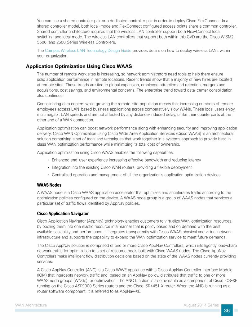
You can use a shared controller pair or a dedicated controller pair in order to deploy Cisco FlexConnect. In a shared controller model, both local-mode and FlexConnect configured access points share a common controller. Shared controller architecture requires that the wireless LAN controller support both Flex-Connect local switching and local mode. The wireless LAN controllers that support both within this CVD are the Cisco WiSM2, 5500, and 2500 Series Wireless Controllers.
The Campus Wireless LAN Technology Design Guide provides details on how to deploy wireless LANs within your organization.
Application Optimization Using Cisco WAASThe number of remote work sites is increasing, so network administrators need tools to help them ensure solid application performance in remote locations. Recent trends show that a majority of new hires are located at remote sites. These trends are tied to global expansion, employee attraction and retention, mergers and acquisitions, cost savings, and environmental concerns. The enterprise trend toward data-center consolidation also continues.
Consolidating data centers while growing the remote-site population means that increasing numbers of remote employees access LAN-based business applications across comparatively slow WANs. These local users enjoy multimegabit LAN speeds and are not affected by any distance-induced delay, unlike their counterparts at the other end of a WAN connection.
Application optimization can boost network performance along with enhancing security and improving application delivery. Cisco WAN Optimization using Cisco Wide Area Application Services (Cisco WAAS) is an architectural solution comprising a set of tools and techniques that work together in a systems approach to provide best-in-class WAN optimization performance while minimizing its total cost of ownership.
Application optimization using Cisco WAAS enables the following capabilities:
• Enhanced end-user experience increasing effective bandwidth and reducing latency
• Integration into the existing Cisco WAN routers, providing a flexible deployment
• Centralized operation and management of all the organization’s application optimization devices
WAAS NodesA WAAS node is a Cisco WAAS application accelerator that optimizes and accelerates traffic according to the optimization policies configured on the device. A WAAS node group is a group of WAAS nodes that services a particular set of traffic flows identified by AppNav policies.
Cisco Application NavigatorCisco Application Navigator (AppNav) technology enables customers to virtualize WAN optimization resources by pooling them into one elastic resource in a manner that is policy based and on demand with the best available scalability and performance. It integrates transparently with Cisco WAAS physical and virtual network infrastructure and supports the capability to expand the WAN optimization service to meet future demands.
The Cisco AppNav solution is comprised of one or more Cisco AppNav Controllers, which intelligently load-share network traffic for optimization to a set of resource pools built with Cisco WAAS nodes. The Cisco AppNav Controllers make intelligent flow distribution decisions based on the state of the WAAS nodes currently providing services.
A Cisco AppNav Controller (ANC) is a Cisco WAVE appliance with a Cisco AppNav Controller Interface Module (IOM) that intercepts network traffic and, based on an AppNav policy, distributes that traffic to one or more WAAS node groups (WNGs) for optimization. The ANC function is also available as a component of Cisco IOS-XE running on the Cisco ASR1000 Series routers and the Cisco ISR4451-X router. When the ANC is running as a router software component, it is referred to as AppNav-XE.
WAN Architecture August 2014 Series37
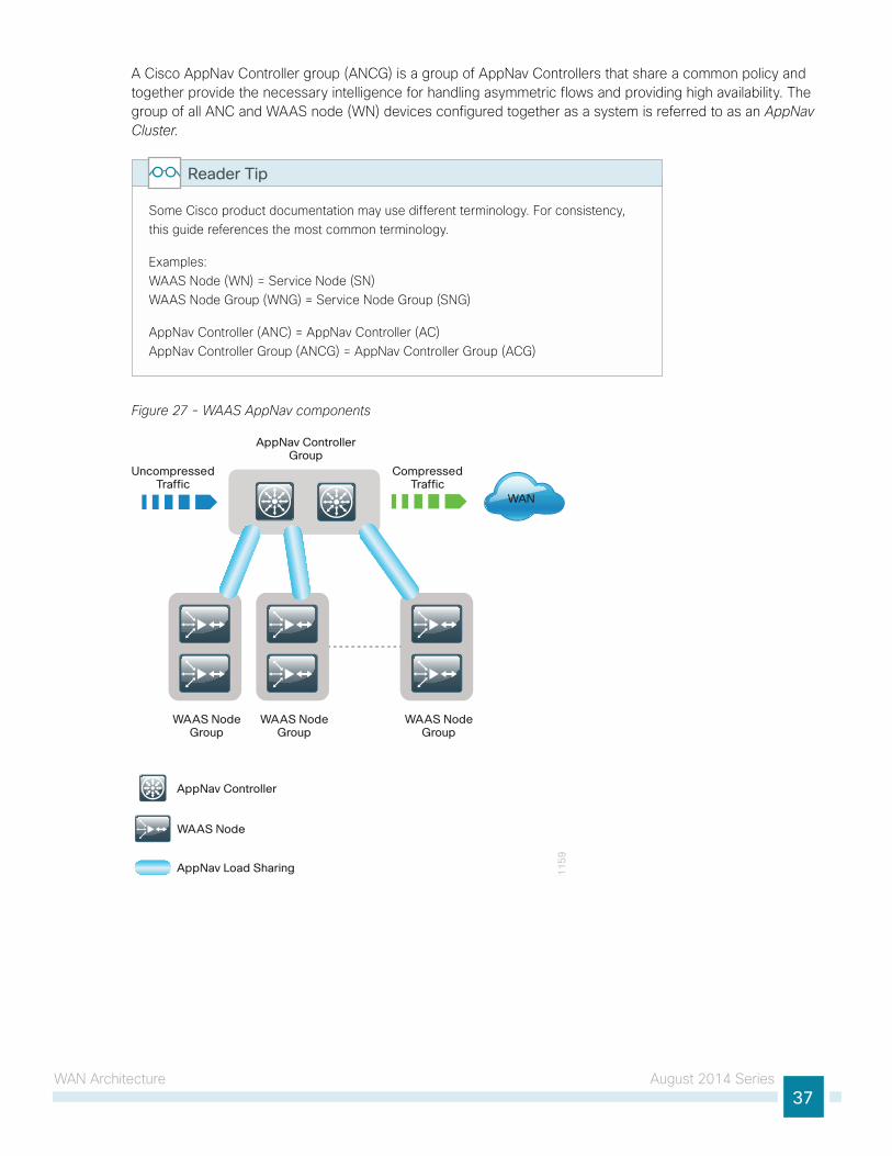
A Cisco AppNav Controller group (ANCG) is a group of AppNav Controllers that share a common policy and together provide the necessary intelligence for handling asymmetric flows and providing high availability. The group of all ANC and WAAS node (WN) devices configured together as a system is referred to as an AppNav Cluster.
Some Cisco product documentation may use different terminology. For consistency, this guide references the most common terminology.
Examples: WAAS Node (WN) = Service Node (SN) WAAS Node Group (WNG) = Service Node Group (SNG)
AppNav Controller (ANC) = AppNav Controller (AC) AppNav Controller Group (ANCG) = AppNav Controller Group (ACG)
Reader Tip
Figure 27 - WAAS AppNav components
WAAS NodeGroup
11
59
WAN
AppNav ControllerGroup
WAAS NodeGroup
WAAS NodeGroup
AppNav Load Sharing
WAAS Node
AppNav Controller
UncompressedTraffic
CompressedTraffic

WAN Architecture August 2014 Series38
AppNav Off-Path Design ModelThe AppNav off-path design is the preferred model for new deployments. This design logically inserts the ANCs between the redirecting routers and the WAAS node group(s). WCCP is still used between the routers and the AppNav controllers, but the WCCP function is strictly limited to redirection and performs no load sharing. AppNav performs the intelligent load sharing.
The connections from the distribution switch to the WAN aggregation routers are routed point-to-point links. This design mandates the use of a generic GRE tunnel between the ANCs and the routers. When a design uses a generic GRE tunnel, it is not required that the ANCs and the WAN aggregation routers are Layer 2 adjacent.
Figure 28 - AppNav off-path deployment model
DMVPNHub Router
WAAS Node Groups
WANDistribution
11
62WAN WAN
CE Routers
DMVPNTunnel
AppNavController
Group
AppNav Load Sharing
Generic GRE Tunnel
Internet Edge
InternetDMVPN Tunnel
WAN Optimization Design ModelsThe WAN optimization design for the remote sites can vary somewhat based on site-specific characteristics. Single router sites use a single (non-redundant) Cisco WAVE appliance or vWAAS instance. Dual-router sites use dual WAVE appliances or vWAAS instances. The specifics of the WAAS sizing and form factor primarily depend on the number of end users and bandwidth of the WAN links.

WAN Architecture August 2014 Series39
Figure 29 - Cisco WAAS topology—Remote-site access-layer design models
11
63
WAN WAN
WAAS NodeWAAS NodeGroup
Negotiated GRE Tunnel
Single WAN Access-Layer Connection Dual WAN Access-Layer Connection
Figure 30 - Cisco WAAS topology—Remote-site distribution-layer design models
WAAS Node Group
11
64
WAN
Negotiated GRE Tunnel
For information about how to deploy this WAN service, see the Application Optimization Using Cisco WAAS Technology Design Guide.
WAN Architecture August 2014 Series40
ISR-WAASThe Cisco ISR4451-X router is the first ISR router to run Cisco IOS-XE Software. The multi-core CPU architecture of the Cisco ISR4451-X supports a built-in services virtualization framework that enables on-demand deployment of services such as a vWAAS instance. The specific implementation of vWAAS running in a Cisco IOS-XE Software container on the Cisco ISR4451-X router is referred to as ISR-WAAS. The term container refers to the keyboard, video, and mouse (KVM) hypervisor that runs virtualized applications on the Cisco ISR4451-X router.
In this virtualization framework, the router is the host machine and the virtual-service is a guest OS. The virtual-service shares CPU and memory resources with the host router. Additionally, to deploy a virtual-service, the router requires additional storage beyond the standard bootflash.
ISR-WAAS Design ModelsThe combination of AppNav-XE and ISR-WAAS on the Cisco ISR4451-X router is entirely self-contained when deployed at a single-router remote-site. Logically, AppNav-XE runs separately on the host OS and ISR-WAAS runs as a guest OS. You configure service insertion on the router and traffic is redirected to ISR-WAAS, but in this case traffic never leaves the router.
Figure 31 - Cisco ISR-WAAS remote-site design models
WAAS NodeGroup
11
61
WAN
AppNav ControllerGroup
AppNav Load Sharing
ISR-WAAS
WAN
ISR-WAAS
AppNav ControllerGroup
WAN
ISR-WAAS
WAAS NodeGroup
The dual-router remote-site provides additional resiliency from a hardware and software perspective. Each router runs AppNav-XE and ISR-WAAS. You configure a single ANCG to distribute traffic for optimization to a single WNG that includes the ISR-WAAS instances from both routers. The application traffic load is shared across both ISR-WAAS instances in the WNG depending on the traffic flows and utilization of each ISR-WAAS. Traffic may be sent between the two routers in order to support this resiliency and load sharing.
For information about how to deploy this WAN service, see the Application Optimization Using Cisco ISR-WAAS Technology Design Guide.
Summary August 2014 Series41
SummaryCisco Validated Designs for enterprise WAN are proven solutions that scale to all remote-site sizes over any transport. With rich application and security services on a single platform, IT can scale to hundreds of sites. Also, customers can maintain granular control, from the remote site, to the data center, and out to the public cloud. The traffic is dynamically routed based on application, endpoint, and network conditions to help ensure the best user experience. IT can confidently roll out critical business services such as consolidated data centers, SaaS, IP telephony, and video without overwhelming the WAN.
The CVD WAN design guides provide step-by-step guidance for deploying the solutions. With Cisco WAN services deployed on the WAN foundation, IT has the security and application services to deliver the highest levels of resiliency and reliability over any of the most common transports.
Americas HeadquartersCisco Systems, Inc.San Jose, CA
Asia Pacific HeadquartersCisco Systems (USA) Pte. Ltd.Singapore
Europe HeadquartersCisco Systems International BV Amsterdam,The Netherlands
Cisco has more than 200 offices worldwide. Addresses, phone numbers, and fax numbers are listed on the Cisco Website at www.cisco.com/go/offices.
ALL DESIGNS, SPECIFICATIONS, STATEMENTS, INFORMATION, AND RECOMMENDATIONS (COLLECTIVELY, “DESIGNS”) IN THIS MANUAL ARE PRESENTED “AS IS,” WITH ALL FAULTS. CISCO AND ITS SUPPLIERS DISCLAIM ALL WARRANTIES, INCLUDING, WITHOUT LIMITATION, THE WARRANTY OF MERCHANTABILITY, FITNESS FOR A PARTICULAR PURPOSE AND NONINFRINGEMENT OR ARISING FROM A COURSE OF DEALING, USAGE, OR TRADE PRACTICE. IN NO EVENT SHALL CISCO OR ITS SUPPLIERS BE LIABLE FOR ANY INDIRECT, SPECIAL, CONSEQUENTIAL, OR INCIDENTAL DAMAGES, INCLUDING, WITHOUT LIMITATION, LOST PROFITS OR LOSS OR DAMAGE TO DATA ARISING OUT OF THE USE OR INABILITY TO USE THE DESIGNS, EVEN IF CISCO OR ITS SUPPLIERS HAVE BEEN ADVISED OF THE POSSIBILITY OF SUCH DAMAGES. THE DESIGNS ARE SUBJECT TO CHANGE WITHOUT NOTICE. USERS ARE SOLELY RESPONSIBLE FOR THEIR APPLICATION OF THE DESIGNS. THE DESIGNS DO NOT CONSTITUTE THE TECHNICAL OR OTHER PROFESSIONAL ADVICE OF CISCO, ITS SUPPLIERS OR PARTNERS. USERS SHOULD CONSULT THEIR OWN TECHNICAL ADVISORS BEFORE IMPLEMENTING THE DESIGNS. RESULTS MAY VARY DEPENDING ON FACTORS NOT TESTED BY CISCO.
Any Internet Protocol (IP) addresses used in this document are not intended to be actual addresses. Any examples, command display output, and figures included in the document are shown for illustrative purposes only. Any use of actual IP addresses in illustrative content is unintentional and coincidental.
© 2014 Cisco Systems, Inc. All rights reserved.
Cisco and the Cisco logo are trademarks or registered trademarks of Cisco and/or its affiliates in the U.S. and other countries. To view a list of Cisco trademarks, go to this URL: www.cisco.com/go/trademarks. Third-party trademarks mentioned are the property of their respective owners. The use of the word partner does not imply a partnership relationship between Cisco and any other company. (1110R)
Please use the feedback form to send comments and suggestions about this guide.
Feedback
B-0000340-1 08/14