Embed Size (px)
Citation preview

WAN Architectures and Design Principles
Stephen LynnConsulting Systems [email protected]
CCIE 5507 (RS/WAN/Sec)CCDE 2013::56
BRKRST-2041
WAN Technologies & Solutions
• WAN Transport Technologies
• WAN Overlay Technologies
• WAN Optimization
• Wide Area Network Quality of Service
WAN Architecture Design Considerations
• WAN Design and Best Practices
• Secure WAN Communication with GETVPN
• Intelligent WAN Deployment
Summary
Agenda
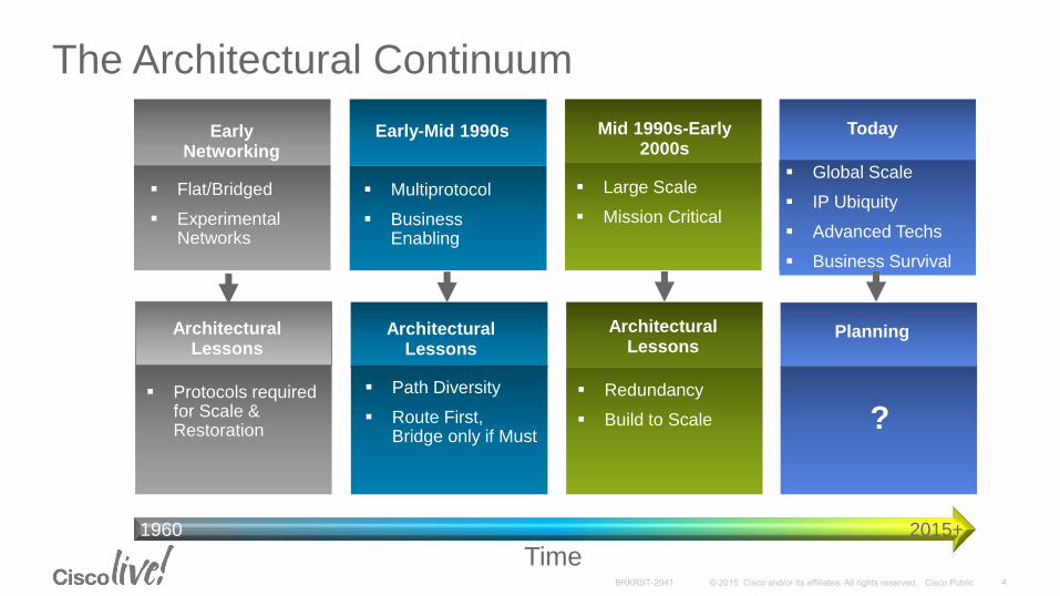
The Architectural Continuum
Early Networking
Multiprotocol
Business Enabling
Early-Mid 1990s
Global Scale
IP Ubiquity
Advanced Techs
Business Survival
Mid 1990s-Early 2000s
Today
Flat/Bridged
Experimental Networks
Architectural Lessons
Path Diversity
Route First, Bridge only if Must
Redundancy
Build to Scale ?
Planning
Protocols required for Scale & Restoration
Large Scale
Mission Critical
Architectural Lessons
Architectural Lessons
Time2015+1960

The Challenge
Build a network that can adapt to a quickly changing business and technical environment
Realize rapid strategic advantage from new technologies
• IPv6: global reachability
• Cloud: flexible diversified resources
• Internet of Things
• Software-Defined WAN
• What’s next?
Adapt to business changes rapidly and smoothly
• Mergers & divestures
• Changes in the regulatory & security requirements
• Changes in public perception of services

East Region
Tie
r 3
Public
IP
Service
Metro
Service
Network Design Modularity
Tie
r 1
Tie
r 2
Global
IP/MPLS Core
West TheaterEast Theater
In-Theater
IP/MPLS Core
Private
IP
Service
Metro
Service
West Region
Internet
Cloud
Public Voice/Video Mobility
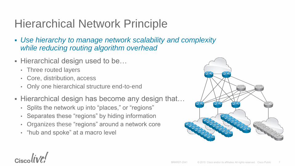
Hierarchical Network Principle
Use hierarchy to manage network scalability and complexity while reducing routing algorithm overhead
Hierarchical design used to be…• Three routed layers
• Core, distribution, access
• Only one hierarchical structure end-to-end
Hierarchical design has become any design that…• Splits the network up into “places,” or “regions”
• Separates these “regions” by hiding information
• Organizes these “regions” around a network core
• “hub and spoke” at a macro level

MPLS L3VPN TopologyDefinition
SpokeSite 1
SpokeSite 2
SpokeSite N
SpokeSite Y
SpokeSite X
SpokeSite 1
SpokeSite N
SpokeSite 2
SpokeSite X
Hub Site(The Network)
SpokeSite Y
Equivalent to
MPLS WAN is provided by a service provider
As seen by the enterprise network, every site is one IP “hop” away
Equivalent to a full mesh, or to a “hubless” hub-and-spoke
SP-Managed
MPLS IP WAN
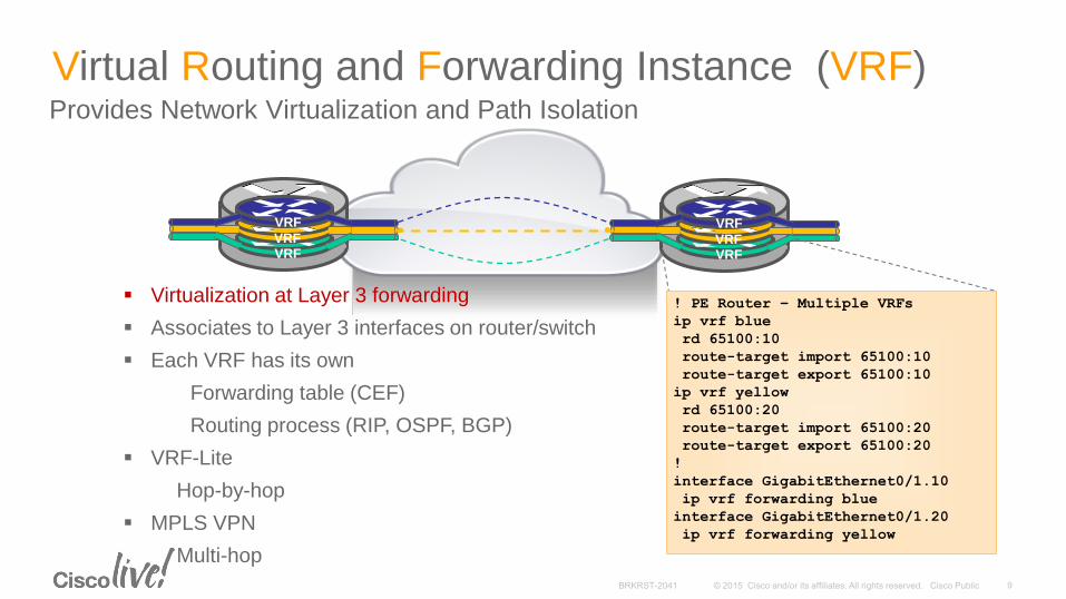
Virtual Routing and Forwarding Instance (VRF)Provides Network Virtualization and Path Isolation
VRF
VRFVRF
VRF
VRFVRF
Virtualization at Layer 3 forwarding
Associates to Layer 3 interfaces on router/switch
Each VRF has its own
Forwarding table (CEF)
Routing process (RIP, OSPF, BGP)
VRF-Lite
Hop-by-hop
MPLS VPN
Multi-hop
! PE Router – Multiple VRFs
ip vrf blue
rd 65100:10
route-target import 65100:10
route-target export 65100:10
ip vrf yellow
rd 65100:20
route-target import 65100:20
route-target export 65100:20
!
interface GigabitEthernet0/1.10
ip vrf forwarding blue
interface GigabitEthernet0/1.20
ip vrf forwarding yellow
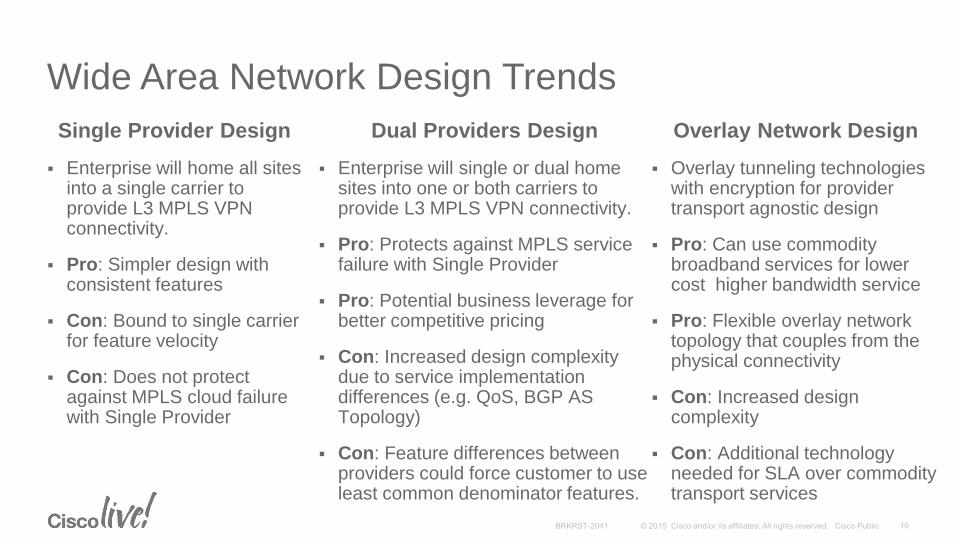
Wide Area Network Design Trends
Single Provider Design
Enterprise will home all sites into a single carrier to provide L3 MPLS VPN connectivity.
Pro: Simpler design with consistent features
Con: Bound to single carrier for feature velocity
Con: Does not protect against MPLS cloud failure with Single Provider
Overlay Network Design
Overlay tunneling technologies with encryption for provider transport agnostic design
Pro: Can use commodity broadband services for lower cost higher bandwidth service
Pro: Flexible overlay network topology that couples from the physical connectivity
Con: Increased design complexity
Con: Additional technology needed for SLA over commodity transport services
Dual Providers Design
Enterprise will single or dual home sites into one or both carriers to provide L3 MPLS VPN connectivity.
Pro: Protects against MPLS service failure with Single Provider
Pro: Potential business leverage for better competitive pricing
Con: Increased design complexity due to service implementation differences (e.g. QoS, BGP AS Topology)
Con: Feature differences between providers could force customer to use least common denominator features.

Single Carrier Site Types (Non-Transit)
Dual Homed Non Transit
Only advertise local prefixes (^$)
Typically with Dual CE routers
BGP design:
eBGP to carrier
iBGP between CEs
Redistribute cloud learned routes into site IGP
Single Homed Non Transit
Advertise local prefixes and optionally use default route.
C1
AS 64512
C2
CE5
Site IGP
CE3 CE4
AS 64517
CE1 CE2
AS 200

AS 100 AS 200
Dual Carrier: Transit vs. Non Transit
C1
CE2
Prefix Z
C2
CE5
Prefix X Prefix Y
Site
IGP
CE3 CE4
AS 64545
CE1
To guarantee single homed site reachability to a dual homed site experiencing a failure, transit sites had to be elected.
Transit sites would act as a BGP bridge transiting routes between the two provider clouds.
To minimize latency costs of transits, transits need to be selected with geographic diversity (e.g. from the East, West and Central US.)
Transit

Single Provider Dual Providers
Pro: Common QoS support
modelPro: More fault domains
Pro: Only one carrier to “tune”Pro: More product offerings to
business
Pro: Reduced head end circuits Pro: Ability to leverage vendors
for better pricing
Pro: Overall simpler designPro: Nice to have a second
vendor option
Con: Carrier failure could be
catastrophic
Con: Increased Bandwidth
“Paying for bandwidth twice”
Con: Do not have another
carrier “in your pocket”
Con: Increased overall design
complexity
Con: May be reduced to
“common denominator” between
carriers
Resiliency Drivers vs. Simplicity
Single vs. Dual Carriers

Metro Ethernet Service (L2VPN)
E-Line (Point-to-Point)
Replaces TDM private line
Point-to-point EVCs offer predictable performance for applications
One or more EVCs allowed per single physical interface (UNI)
Ideal for voice, video, and real-time data
E-LAN (Point-to-Multipoint)
Offers point to multipoint for any-to-any connectivity
Transparent to VLANs and Layer 2 control protocols
4 or 6 classes of QoS support
Ideal for LAN-to-LAN bulk data
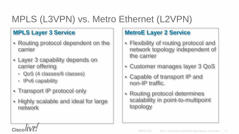
MPLS (L3VPN) vs. Metro Ethernet (L2VPN)
MPLS Layer 3 Service
Routing protocol dependent on the carrier
Layer 3 capability depends on carrier offering
• QoS (4 classes/6 classes)
• IPv6 capability
Transport IP protocol only
Highly scalable and ideal for large network
MetroE Layer 2 Service
Flexibility of routing protocol and network topology independent of the carrier
Customer manages layer 3 QoS
Capable of transport IP and non-IP traffic.
Routing protocol determines scalability in point-to-multipoint topology
WAN Technologies & Solutions
• WAN Transport Technologies
• WAN Overlay Technologies
• WAN Optimization
• Wide Area Network Quality of Service
WAN Architecture Design Considerations
• WAN Design and Best Practices
• Secure WAN Communication with GETVPN
• Intelligent WAN Deployment
Summary
Agenda

Types of Overlay Service
Layer 2 Overlays
• Layer 2 Tunneling Protocol—Version 3 (L2TPv3)
– Layer 2 payloads (Ethernet, Serial,…)
– Pseudowire capable
• Other L2 overlay technologies –OTV, VxLAN
Layer 3 Overlays
• IPSec—Encapsulating Security Payload (ESP)
– Strong encryption
– IP Unicast only
• Generic Routing Encapsulation (GRE)
– IP Unicast, Multicast, Broadcast
– Multiprotocol support
• Other L3 overlay technologies –MPLSomGRE, LISP, OTP

IP HDR
Encrypted
ESP HDR
IP HDR
IP Payload
IPSec Tunnel mode
IPSec Transport modeESP
Trailer
ESP
Auth
Authenticated
EncryptedAuthenticated
TunnelingGRE and IPSec Transport and Tunnel Modes
IP Payload
IP Payload
IP HDRESP HDRIP HDRESP
Trailer
ESP
Auth
20 bytes
30 bytes
54 bytes
2 bytes
2 bytes
IP HDR IP PayloadGREIP HDR
20 bytes
GRE packet with new IP header: Protocol 47 (forwarded using new IP dst)
4 bytes20 bytes

Locator/Identifier Separation Protocol (LISP)Dynamic Tunneling Analogous to a DNS but for Network Infrastructure
DNS resolves IP addresses for URLs
LISP resolves locators for queried identities
DNS
URL Resolution
LISP
Identity-to-location
Map Resolution
host
[ who is www.cisco.com] ?
LISP
router
DNS
Server
LISP
Mapping
System
[153.16.5.29, 2610:D0:110C:1::3 ]
[ where is 2610:D0:110C:1::3] ?
[ location is 128.107.81.169 ]
This Topic Is Covered in Detail in BRKRST-3045
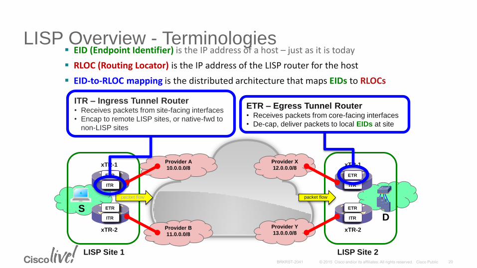
EID (Endpoint Identifier) is the IP address of a host – just as it is today
RLOC (Routing Locator) is the IP address of the LISP router for the host
EID-to-RLOC mapping is the distributed architecture that maps EIDs to RLOCs
LISP Overview - Terminologies
S
xTR-1
LISP Site 1
xTR-2
Provider A
10.0.0.0/8
Provider B
11.0.0.0/8
Provider X
12.0.0.0/8
Provider Y
13.0.0.0/8
ETR
ITR
ETR
ITR
xTR-1
LISP Site 2
xTR-2
ETR
ITR
ETR
ITR
D
packet flow packet flow
ITR – Ingress Tunnel Router• Receives packets from site-facing interfaces
• Encap to remote LISP sites, or native-fwd to
non-LISP sites
ETR – Egress Tunnel Router• Receives packets from core-facing interfaces
• De-cap, deliver packets to local EIDs at site

LISP Operation ExampleLISP Data Plane - Unicast Packet Forwarding
S
xTR-1
LISP Site 1
xTR-2
Provider A
10.0.0.0/8
Provider B
11.0.0.0/8
Provider X
12.0.0.0/8
Provider Y
13.0.0.0/8
ETR
ITR
ETR
ITR
xTR-1
LISP Site 2
xTR-2
ETR
ITR
ETR
ITR
D
PI EID-prefix
2001:db8:1::/48
PI EID-prefix
2001:db8:2::/48
DNS entry:
D.abc.com AAAA 2001:db8:2::1
1
10.0.0.2
11.0.0.2
12.0.0.2
13.0.0.2
2001:db8:1::1 -> 2001:db8:2::12
EID-prefix: 2001:db8:2::/48
Locator-set:
12.0.0.2, priority: 1, weight: 50 (D1)
13.0.0.2, priority: 1, weight: 50 (D2)
Map-Cache Entry
3
2001:db8:1::1 -> 2001:db8:2::1
11.0.0.2 -> 12.0.0.2
4
5
2001:db8:1::1 -> 2001:db8:2::1
11.0.0.2 -> 12.0.0.26
7
2001:db8:1::1 -> 2001:db8:2::1
This policy controlled
by the destination site
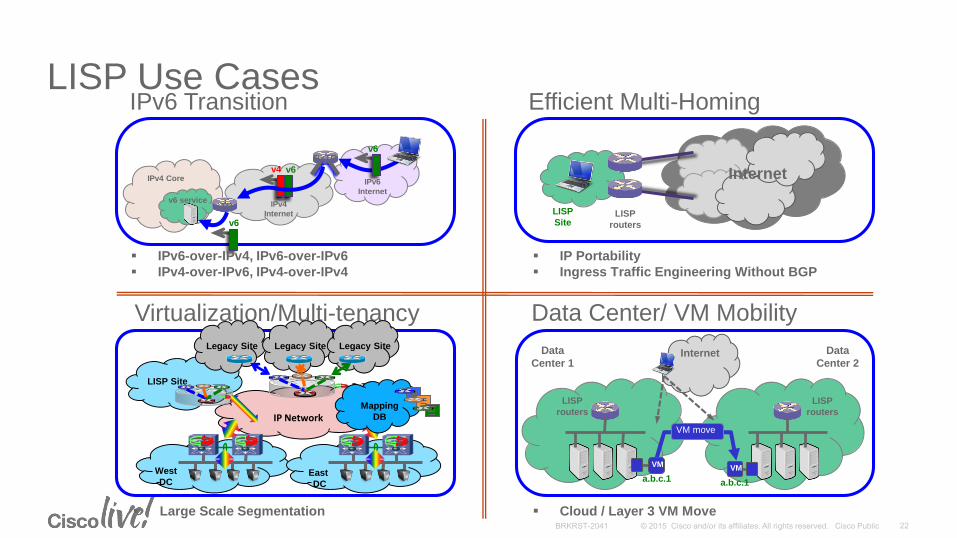
LISP Use Cases
IPv4
Internet
IPv6
Internet
v6
v6v4
PxTR
IPv4 Core
v6
xTRv6 service
IPv6 Transition
LISP
routers
LISP
Site
Internet
Efficient Multi-Homing
Virtualization/Multi-tenancy
Data
Center 1
Data
Center 2
a.b.c.1
VM
a.b.c.1
VM
VM move
LISP
routers
LISP
routers
Internet
Data Center/ VM Mobility
IP Network
West
DC
LISP Site
Legacy Site Legacy Site Legacy Site
East
DC
PxTR
Mapping
DB
IP Portability
Ingress Traffic Engineering Without BGP
IPv6-over-IPv4, IPv6-over-IPv6
IPv4-over-IPv6, IPv4-over-IPv4
Large Scale Segmentation Cloud / Layer 3 VM Move
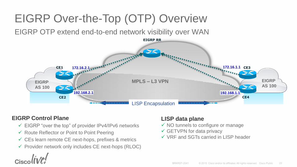
EIGRP Over-the-Top (OTP) OverviewEIGRP OTP extend end-to-end network visibility over WAN
MPLS – L3 VPN
CE1
EIGRP
AS 100
EIGRP
AS 100
CE2
172.16.1.1172.16.2.1
192.168.2.1 192.168.1.1
EIGRP RR
CE3
CE4
LISP Encapsulation
EIGRP Control Plane
EIGRP “over the top” of provider IPv4/IPv6 networks
Route Reflector or Point to Point Peering
CEs learn remote CE next-hops, prefixes & metrics
Provider network only includes CE next-hops (RLOC)
LISP data plane NO tunnels to configure or manage
GETVPN for data privacy
VRF and SGTs carried in LISP header
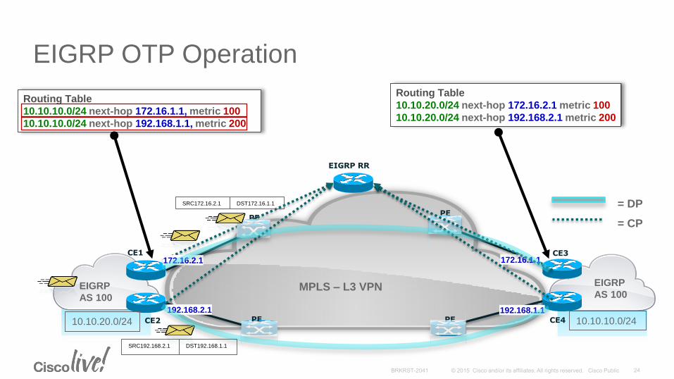
EIGRP OTP Operation
PEPE
CE3CE1
EIGRP
AS 100
EIGRP
AS 100
PECE2 PE CE4
Routing Table
10.10.10.0/24 next-hop 172.16.1.1, metric 100
10.10.10.0/24 next-hop 192.168.1.1, metric 200
10.10.10.0/2410.10.20.0/24
172.16.1.1172.16.2.1
192.168.2.1 192.168.1.1
Routing Table
10.10.20.0/24 next-hop 172.16.2.1 metric 100
10.10.20.0/24 next-hop 192.168.2.1 metric 200
= DP
= CP
EIGRP RR
SRC172.16.2.1 DST172.16.1.1
SRC192.168.2.1 DST192.168.1.1
MPLS – L3 VPN

WAN Virtualization using OTP
• Single routing protocol solution
• Simple configuration and deployment for both IPv4 and IPv6
• Convergence is not depending on Service Provider
• Only the CE needs to be upgraded
• Routes are carried over the Service Provider’s network, not though it
• No artificial limitation on number of routes being exchanged between sites
• Convergence speed not impacted by BGP timers
• Works with both traditional managed and non-managed internet connections
• Compliments an L3 Any-to-Any architecture (optional hair pinning of traffic)
• Support for multiple MPLS VPN connections
• Support for connections not part of the MPLS VPN (“backdoor” links)
Enterprise Benefits
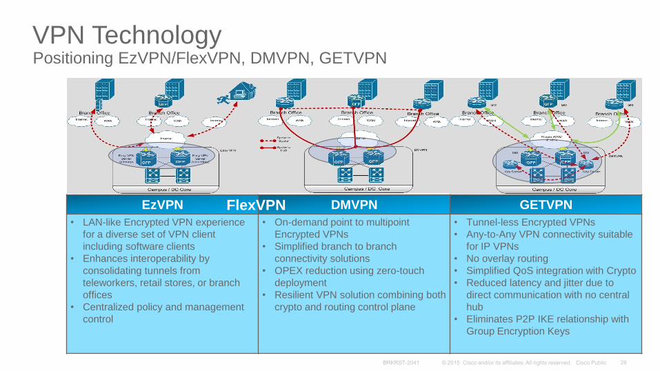
VPN TechnologyPositioning EzVPN/FlexVPN, DMVPN, GETVPN
EzVPN DMVPN GETVPN
• LAN-like Encrypted VPN experience
for a diverse set of VPN client
including software clients
• Enhances interoperability by
consolidating tunnels from
teleworkers, retail stores, or branch
offices
• Centralized policy and management
control
• On-demand point to multipoint
Encrypted VPNs
• Simplified branch to branch
connectivity solutions
• OPEX reduction using zero-touch
deployment
• Resilient VPN solution combining both
crypto and routing control plane
• Tunnel-less Encrypted VPNs
• Any-to-Any VPN connectivity suitable
for IP VPNs
• No overlay routing
• Simplified QoS integration with Crypto
• Reduced latency and jitter due to
direct communication with no central
hub
• Eliminates P2P IKE relationship with
Group Encryption Keys
FlexVPN
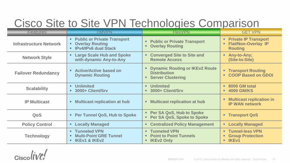
Cisco Site to Site VPN Technologies ComparisonFeatures DMVPN FlexVPN GET VPN
Infrastructure Network Public or Private Transport Overlay Routing IPv4/IPv6 dual Stack
Public or Private Transport Overlay Routing
Private IP Transport Flat/Non-Overlay IP
Routing
Network Style Large Scale Hub and Spoke
with dynamic Any-to-Any Converged Site to Site and
Remote Access Any-to-Any;
(Site-to-Site)
Failover Redundancy Active/Active based on
Dynamic Routing
Dynamic Routing or IKEv2 Route Distribution
Server Clustering
Transport Routing COOP Based on GDOI
Scalability Unlimited 3000+ Client/Srv
Unlimited 3000+ Client/Srv
8000 GM total 4000 GM/KS
IP Multicast Multicast replication at hub Multicast replication at hub Multicast replication in
IP WAN network
QoS Per Tunnel QoS, Hub to Spoke Per SA QoS, Hub to Spoke Per SA QoS, Spoke to Spoke
Transport QoS
Policy Control Locally Managed Centralized Policy Management Locally Managed
Technology Tunneled VPN Multi-Point GRE Tunnel IKEv1 & IKEv2
Tunneled VPN Point to Point Tunnels IKEv2 Only
Tunnel-less VPN Group Protection IKEv1
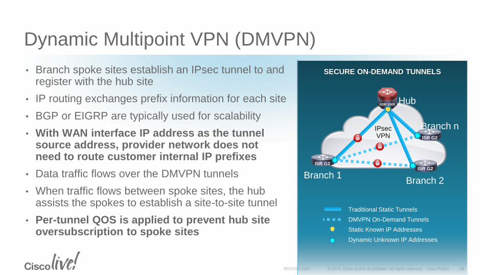
SECURE ON-DEMAND TUNNELS
Dynamic Multipoint VPN (DMVPN)
• Branch spoke sites establish an IPsec tunnel to and register with the hub site
• IP routing exchanges prefix information for each site
• BGP or EIGRP are typically used for scalability
• With WAN interface IP address as the tunnel source address, provider network does not need to route customer internal IP prefixes
• Data traffic flows over the DMVPN tunnels
• When traffic flows between spoke sites, the hub assists the spokes to establish a site-to-site tunnel
• Per-tunnel QOS is applied to prevent hub site oversubscription to spoke sites
Branch 2
Traditional Static Tunnels
DMVPN On-Demand Tunnels
Static Known IP Addresses
Dynamic Unknown IP Addresses
ISR G2
Branch 1
Hub
IPsecVPN
Branch n
ASR 1000
ISR G2ISR G2

© 2014 Cisco and/or its affiliates. All rights reserved.
DMVPN – How it Works
• Spokes build a dynamic permanent GRE/IPsec tunnel to the hub, but not to other spokes. They register as clients of the NHRP server (hub) and register their NBMA address
• Active-Active redundancy model—two or more hubs per spoke
• All configured hubs are active and are routing neighbors with spokes
• Routing protocol routes are used to determine traffic forwarding
• A spoke will initially send a packet to a destination (private) subnet behind another spoke via the hub, and the hub will send it an NHRP redirect.
• The redirect triggers the spoke to send an NHRP query for the data packet destination address behind the destination spoke
• The destination spoke initiates a dynamic GRE/IPsec tunnel to the source spoke (it now knows its NBMA address) and sends the NHRP reply.
• The dynamic spoke-to-spoke tunnel is built over the mGRE interface
• When traffic ceases then the spoke-to-spoke tunnel is removed
192.168.0.0/24
Physical: 172.17.0.5
Tunnel0: 10.0.1.1
Physical: 172.17.0.1
Tunnel0: 10.0.0.1
Physical: (dynamic)
Tunnel0: 10.0.0.12
Tunnel1: 10.0.1.12
192.168.3.0/24
.1
Physical: (dynamic)
Tunnel0: 10.0.0.11
Tunnel1: 10.0.1.11
192.168.1.0 /24
.1
Dual DMVPN Design
Single mGRE tunnel on Hub,
two mGRE tunnels on Spokes
192.168.2.0 /24
.1

DMVPN Network Designs
Hub and spoke Spoke-to-spoke
Server Load Balancing Hierarchical
Spoke-to-hub tunnels
Spoke-to-spoke tunnels
2547oDMVPN tunnels
VRF-lite
2547oDMVPN
Incre
ase in
Scale

Any-to-Any EncryptionBefore and After GETVPN
Scalability—an issue (N^2 problem)
Overlay routing
Any-to-any instant connectivity can’t be done to scale
Limited QoS
Inefficient Multicast replication
Multicast
Before: IPSec P2P Tunnels After: Tunnel-Less VPN
Scalable architecture for any-to-any connectivity and encryption
No overlays—native routing
Any-to-any instant connectivity
Enhanced QoS
Efficient Multicast replication
Public/Private WAN Private WAN
WAN
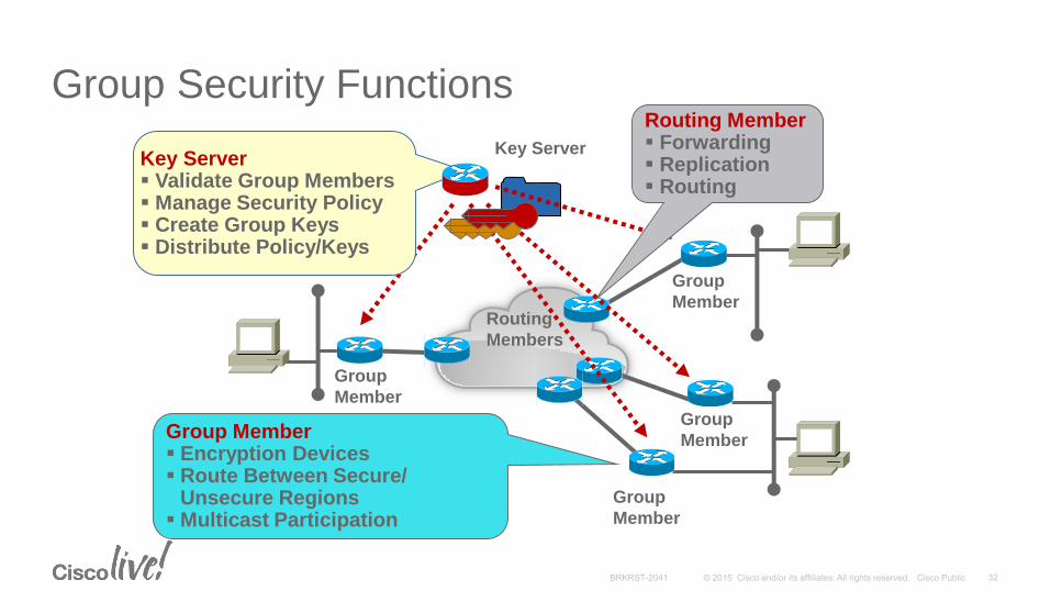
Group Security Functions
Group
Member
Group
Member
Group
Member
Group
Member
Key Server
Routing
Members
Group Member Encryption Devices Route Between Secure/
Unsecure Regions Multicast Participation
Key Server Validate Group Members Manage Security Policy Create Group Keys Distribute Policy/Keys
Routing Member Forwarding Replication Routing

Group Security Elements
Group
Member
Group
Member
Group
Member
Group
Member
Key Servers
Routing
Members
Key Encryption Key (KEK)
Traffic Encryption Key (TEK)
Group Policy
RFC3547:Group Domain of Interpretation (GDOI)
KS Cooperative Protocol

GETVPN - Group Key TechnologyOperation Example
Step 1: Group Members (GM) “register” via GDOI (IKE) with the Key Server (KS)
• KS authenticates and authorizes the GM
• KS returns a set of IPsec SAsfor the GM to use
Step 2: Data Plane Encryption
• GM exchange encrypted traffic using the group keys
• The traffic uses IPSec Tunnel Mode with “address preservation”
Step 3: Periodic Rekey of Keys
• KS pushes out replacement IPsec keys before current IPsec keys expire; This is called a “rekey”
GM1
GM2
GM3GM4
GM5
GM6
GM7GM8
GM9 KS
GM1
GM2
GM3GM4
GM5
GM6
GM7GM8
GM9 KS
GM1
GM2
GM3GM4
GM5
GM6
GM7GM8
GM9 KS
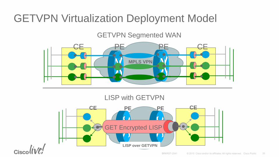
GETVPN Virtualization Deployment Model
MPLS VPN
CE CEPE PE
LISP over GETVPN
GET Encrypted LISP
CE PE PE CE
GETVPN Segmented WAN
LISP with GETVPN

Market Transition – Ethernet WAN Transport
MACsec Layer 2 Encryption for WAN
Ethernet is not only in the campus and data center any longer
Ethernet is growing rapidly as a WAN & Metro “transport” service
WAN/Metro SP offerings are replacing existing T1, ATM/FR, and SONET OC-x options
Ethernet services apply to many areas of the WAN/MAN:
• WAN links for core, edge, remote branch
• PE-CE links (leveraging L3 VPN services)
• Metro-E service hand-offs (P2P, P2MP)
Cisco’s goal is to integrate MACsec as part of new Ethernet interface/LC development moving forward on routers leveraged in WAN, MAN, Branch
ASR 1001-X XE3.14
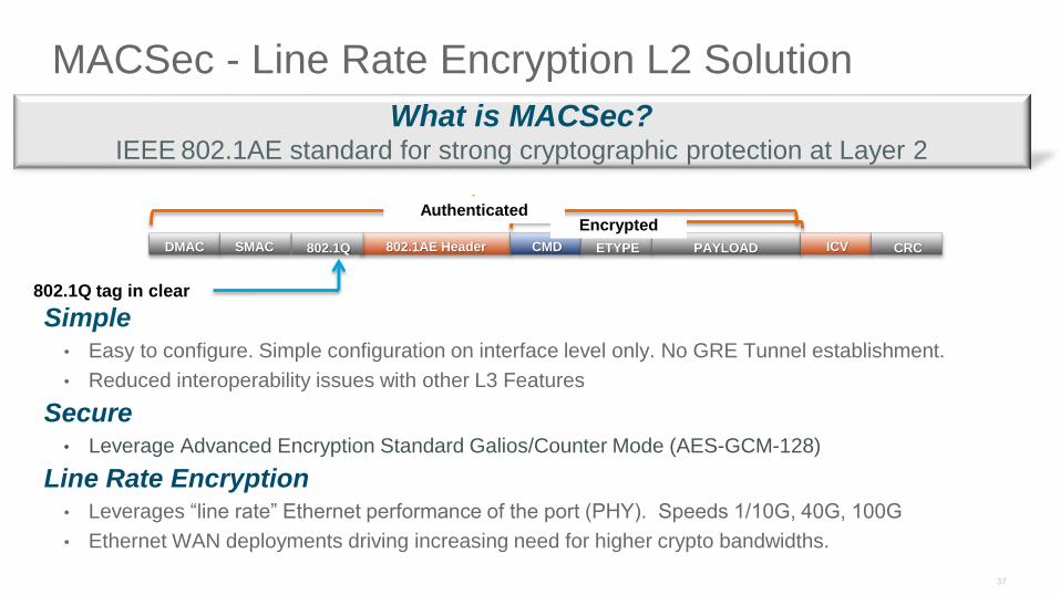
MACSec - Line Rate Encryption L2 Solution
Simple• Easy to configure. Simple configuration on interface level only. No GRE Tunnel establishment.
• Reduced interoperability issues with other L3 Features
Secure• Leverage Advanced Encryption Standard Galios/Counter Mode (AES-GCM-128)
Line Rate Encryption• Leverages “line rate” Ethernet performance of the port (PHY). Speeds 1/10G, 40G, 100G
• Ethernet WAN deployments driving increasing need for higher crypto bandwidths.
What is MACSec?IEEE 802.1AE standard for strong cryptographic protection at Layer 2
DMAC SMAC 802.1AE Header802.1Q CMD ETYPE PAYLOAD ICV CRC
802.1Q tag in clear
ß
EncryptedAuthenticated
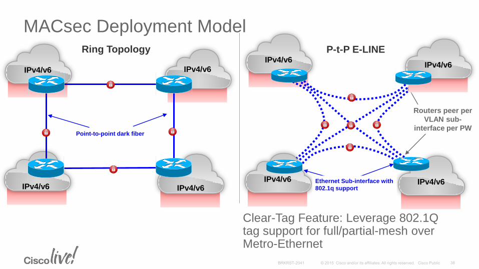
IPv4/v6
IPv4/v6 IPv4/v6
IPv4/v6
IPv4/v6
MACsec Deployment Model
CE2
CE3CE4
Routers peer per
VLAN sub-
interface per PW
Ring Topology P-t-P E-LINE
IPv4/v6 IPv4/v6
IPv4/v6
Ethernet Sub-interface with
802.1q support
Point-to-point dark fiber
Clear-Tag Feature: Leverage 802.1Q tag support for full/partial-mesh over Metro-Ethernet
WAN Technologies & Solutions
• WAN Transport Technologies
• WAN Overlay Technologies
• WAN Optimization
• Wide Area Network Quality of Service
WAN Architecture Design Considerations
• WAN Design and Best Practices
• Secure WAN Communication with GETVPN
• Intelligent WAN Deployment
Summary
Agenda
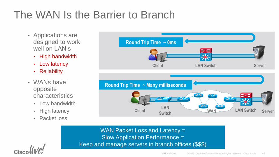
The WAN Is the Barrier to Branch Application Performance
Applications are designed to work well on LAN’s
• High bandwidth
• Low latency
• Reliability
WANs have opposite characteristics
• Low bandwidth
• High latency
• Packet loss
WAN Packet Loss and Latency =
Slow Application Performance =
Keep and manage servers in branch offices ($$$)
ServerLAN SwitchClient
Round Trip Time ~ 0ms
LAN
Switch ServerLAN SwitchClient WAN
Round Trip Time ~ Many milliseconds
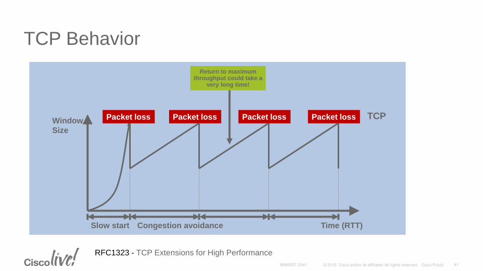
TCP Behavior
Time (RTT)Slow start Congestion avoidance
Packet loss Packet loss Packet lossWindow
Size
Packet loss TCP
Return to maximumthroughput could take a
very long time!
RFC1323 - TCP Extensions for High Performance
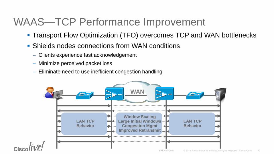
WAAS—TCP Performance Improvement Transport Flow Optimization (TFO) overcomes TCP and WAN bottlenecks
Shields nodes connections from WAN conditions
– Clients experience fast acknowledgement
– Minimize perceived packet loss
– Eliminate need to use inefficient congestion handling
LAN TCPBehavior
LAN TCPBehavior
Window ScalingLarge Initial Windows
Congestion MgmtImproved Retransmit
WAN

WAAS Advanced CompressionDRE and LZ Manage Bandwidth Utilization
Synchronized
Compression
History
DRE
LZ LZ
DRE
Data Redundancy Elimination
(DRE)
•Application-agnostic compression
•Up to 100:1 compression
•WAAS 4.4: Context Aware DRE
WAN
Benefits
• Application-agnostic compression
• Up to 100:1 compression
• WAAS 4.4: Context Aware DRE
•Session-based compression
•Up to 10:1 compression
•Works even during cold DRE cache
Persistent LZ Compression
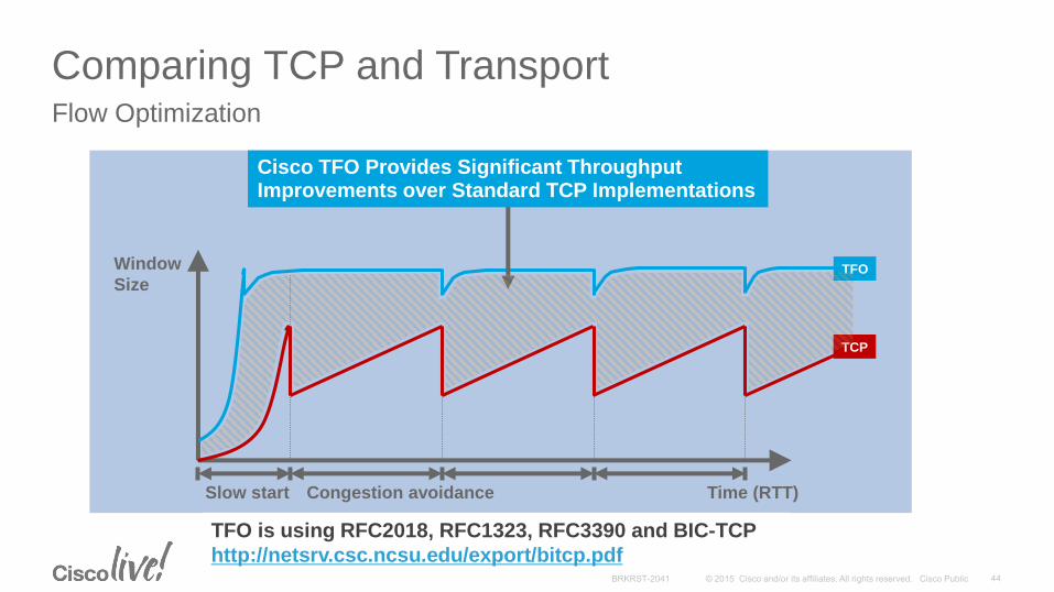
Comparing TCP and Transport Flow Optimization
Time (RTT)Slow start Congestion avoidance
TCP
TFOWindow
Size
Cisco TFO Provides Significant Throughput Improvements over Standard TCP Implementations
TFO is using RFC2018, RFC1323, RFC3390 and BIC-TCP
http://netsrv.csc.ncsu.edu/export/bitcp.pdf

Cisco WAAS: WAN Optimization Deployment
Branch Office
WAAS
Service
Module/ UCSe
Branch OfficeWAAS
Express
Branch Office
WAAS
Appliance
Regional OfficeWAAS
Appliance
Data Center or
Private CloudWAAS
Appliances
VMware ESXi
vWAAS
Appliances
Server VMs
AppNav +
WAAS
Regional OfficeWAAS-XE
on 4451
WAN
Internet
vWAAS
WAEServer
VMs
VMware ESXi Server
Nexus 1000v vPATH
UCS /x86 Server
FC SAN
Nexus 1000v VSM
Virtual Private Cloud
WAN Technologies & Solutions
• WAN Transport Technologies
• WAN Overlay Technologies
• WAN Optimization
• Wide Area Network Quality of Service
WAN Architecture Design Considerations
• WAN Design and Best Practices
• Secure WAN Communication with GETVPN
• Intelligent WAN Deployment
Summary
Agenda
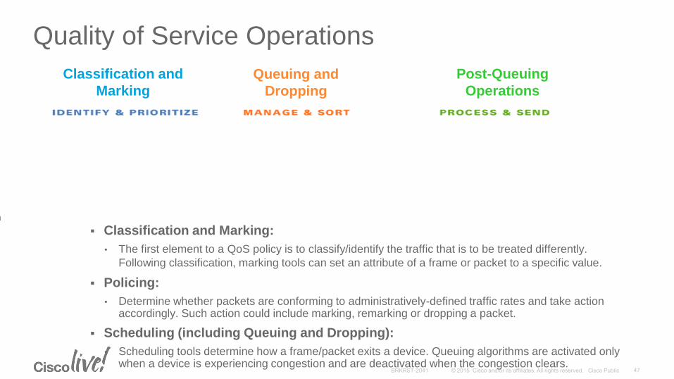
Quality of Service OperationsHow Does It Work and Essential Elements
Classification and Marking:
• The first element to a QoS policy is to classify/identify the traffic that is to be treated differently.
Following classification, marking tools can set an attribute of a frame or packet to a specific value.
Policing:
• Determine whether packets are conforming to administratively-defined traffic rates and take action accordingly. Such action could include marking, remarking or dropping a packet.
Scheduling (including Queuing and Dropping):
• Scheduling tools determine how a frame/packet exits a device. Queuing algorithms are activated only when a device is experiencing congestion and are deactivated when the congestion clears.
Classification and
Marking
Queuing and
Dropping
Post-Queuing
Operations
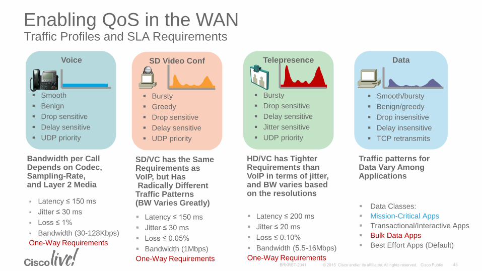
Enabling QoS in the WANTraffic Profiles and SLA Requirements
Latency ≤ 150 ms
Jitter ≤ 30 ms
Loss ≤ 1%
Bandwidth (30-128Kbps)
One-Way Requirements
Smooth
Benign
Drop sensitive
Delay sensitive
UDP priority
Voice
Bandwidth per CallDepends on Codec,Sampling-Rate, and Layer 2 Media
Bursty
Drop sensitive
Delay sensitive
Jitter sensitive
UDP priority
Telepresence
Latency ≤ 200 ms
Jitter ≤ 20 ms
Loss ≤ 0.10%
Bandwidth (5.5-16Mbps)
One-Way Requirements
HD/VC has TighterRequirements thanVoIP in terms of jitter, and BW varies based on the resolutions
Smooth/bursty
Benign/greedy
Drop insensitive
Delay insensitive
TCP retransmits
Data
Data Classes:
Mission-Critical Apps
Transactional/Interactive Apps
Bulk Data Apps
Best Effort Apps (Default)
Traffic patterns for Data Vary Among Applications
Bursty
Greedy
Drop sensitive
Delay sensitive
UDP priority
SD Video Conf
Latency ≤ 150 ms
Jitter ≤ 30 ms
Loss ≤ 0.05%
Bandwidth (1Mbps)
One-Way Requirements
SD/VC has the SameRequirements as VoIP, but HasRadically Different
Traffic Patterns (BW Varies Greatly)
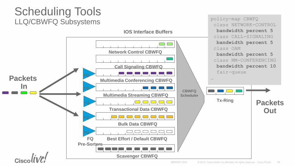
Packets In
PacketsOut
IOS Interface Buffers
Tx-Ring
Multimedia Conferencing CBWFQ
Multimedia Streaming CBWFQ
Network Control CBWFQ
Call Signaling CBWFQ
Transactional Data CBWFQ
Bulk Data CBWFQ
Best Effort / Default CBWFQ
Scavenger CBWFQ
CBWFQ
Scheduler
FQ
FQ
FQ
FQ
Pre-Sorters
FQ
FQ
policy-map CBWFQ
class NETWORK-CONTROL
bandwidth percent 5
class CALL-SIGNALING
bandwidth percent 5
class OAM
bandwidth percent 5
class MM-CONFERENCING
bandwidth percent 10
fair-queue
…
Scheduling ToolsLLQ/CBWFQ Subsystems

Packets In
PacketsOut
IOS Interface Buffers
Tx-Ring
CBWFQ
Scheduler
LLQ
1 Mbps
VoIP
Policer
5 Mbps
RT-Interactive
Policer
CBWFQ
policy-map MULTI-LLQ
class VOIP
priority 1000
class REALTIME-INTERACTIVE
priority 5000
…
Scheduling ToolsLLQ/CBWFQ Subsystems

Traffic Shaping
Policers typically drop traffic
Shapers typically delay excess traffic, smoothing bursts and preventing unnecessary drops
Very common with Ethernet WAN, as well as Non-Broadcast Multiple-Access (NBMA) network topologies such as Frame-Relay and ATM
With Traffic Shaping
Without Traffic ShapingLineRate
ShapedRate
Traffic Shaping Limits the Transmit Rate to a Value Lower Than Line Rate
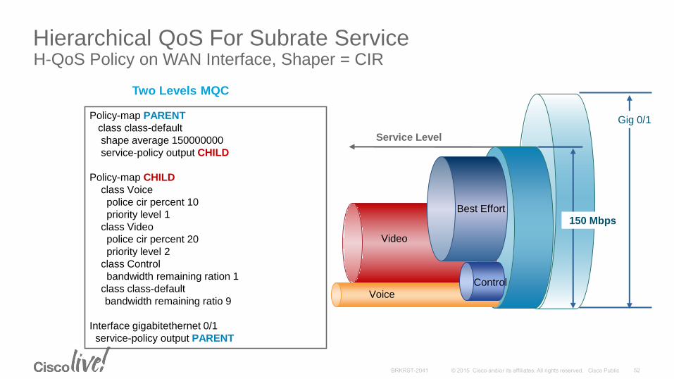
Hierarchical QoS For Subrate ServiceH-QoS Policy on WAN Interface, Shaper = CIR
150 Mbps
Service Level
Policy-map PARENT
class class-default
shape average 150000000
service-policy output CHILD
Policy-map CHILD
class Voice
police cir percent 10
priority level 1
class Video
police cir percent 20
priority level 2
class Control
bandwidth remaining ration 1
class class-default
bandwidth remaining ratio 9
Interface gigabitethernet 0/1
service-policy output PARENT
Two Levels MQC
Voice
Video
Best Effort
Control
Gig 0/1
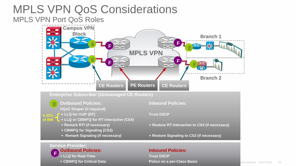
MPLS VPN
Branch 1
Branch 2
Outbound Policies: Inbound Policies:
HQoS Shaper (if required)
+ LLQ for VoIP (EF) Trust DSCP
+ LLQ or CBWFQ for RT-Interactive (CS4)
+ Remark RTI (if necessary) + Restore RT-Interactive to CS4 (if necessary)
+ CBWFQ for Signaling (CS3)
+ Remark Signaling (if necessary) + Restore Signaling to CS3 (if necessary)
≤ 33%of BW
Enterprise Subscriber (Unmanaged CE Routers)
Service Provider:Outbound Policies: Inbound Policies:
+ LLQ for Real-Time Trust DSCP
+ CBWFQ for Critical Data Police on a per-Class Basis
CE Routers CE RoutersPE Routers
Campus VPN
Block
E
E
E
E
F
F
F
F
F
E
MPLS VPN QoS ConsiderationsMPLS VPN Port QoS Roles
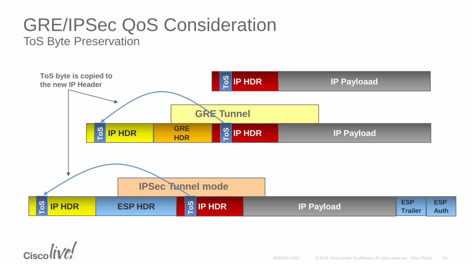
IP HDRGRE
HDR
IP HDR
IP Payload
IPSec Tunnel mode
GRE Tunnel
GRE/IPSec QoS ConsiderationToS Byte Preservation
IP Payloaad
IP Payload
ESP HDRIP HDRESP
Trailer
ESP
AuthIP HDR
IP HDR
To
SToS byte is copied to
the new IP Header
To
S
To
S
To
S
To
S
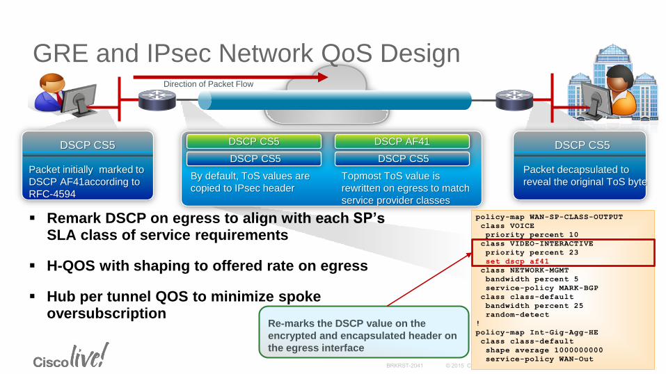
GRE and IPsec Network QoS DesignDirection of Packet Flow
DSCP CS5
Packet initially marked to
DSCP AF41according to
RFC-4594
DSCP CS5
Packet decapsulated to
reveal the original ToS byte
DSCP CS5 DSCP AF41
DSCP CS5
By default, ToS values are
copied to IPsec header
DSCP CS5
Topmost ToS value is
rewritten on egress to match
service provider classes
policy-map WAN-SP-CLASS-OUTPUT
class VOICE
priority percent 10
class VIDEO-INTERACTIVE
priority percent 23
set dscp af41
class NETWORK-MGMT
bandwidth percent 5
service-policy MARK-BGP
class class-default
bandwidth percent 25
random-detect
!
policy-map Int-Gig-Agg-HE
class class-default
shape average 1000000000
service-policy WAN-Out
Re-marks the DSCP value on the
encrypted and encapsulated header on
the egress interface
Remark DSCP on egress to align with each SP’sSLA class of service requirements
H-QOS with shaping to offered rate on egress
Hub per tunnel QOS to minimize spoke oversubscription
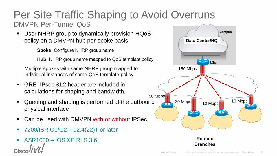
Per Site Traffic Shaping to Avoid OverrunsDMVPN Per-Tunnel QoS
CE
Remote
Branches
Campus
50 Mbps
10 Mbps10 Mbps
150 Mbps
20 Mbps
Data Center/HQ
User NHRP group to dynamically provision HQoS
policy on a DMVPN hub per-spoke basis
Spoke: Configure NHRP group name
Hub: NHRP group name mapped to QoS template policy
Multiple spokes with same NHRP group mapped to
individual instances of same QoS template policy
GRE ,IPsec &L2 header are included in
calculations for shaping and bandwidth.
Queuing and shaping is performed at the outbound
physical interface
Can be used with DMVPN with or without IPSec.
7200/ISR G1/G2 – 12.4(22)T or later
ASR1000 – IOS XE RLS 3.6

Per-tunnel QoSConfigurations
class-map match-all typeA_voicematch access-group 100
class-map match-all typeB_voicematch access-group 100
class-map match-all typeA_Routingmatch ip precedence 6
class-map match-all typeB_Routingmatch ip precedence 6
policy-map typeAclass typeA_voice
priority 1000class typeA_Routing
bandwidth percent 20
policy-map typeBclass typeB_voice
priority percent 20class typeB_Routing
bandwidth percent 10
policy-map typeA_parentclass class-default
shape average 3000000service-policy typeA
policy-map typeB_parentclass class-default
shape average 2000000service-policy typeB
interface Tunnel0ip address 10.0.0.1 255.255.255.0…ip nhrp map group typeA service-policy output typeA_parentip nhrp map group typeB service-policy output typeB_parent…ip nhrp redirectno ip split-horizon eigrp 100ip summary-address eigrp 100 192.168.0.0 255.255.192.0 5…
interface Tunnel0ip address 10.0.0.11 255.255.255.0…ip nhrp group typeAip nhrp map multicast 172.17.0.1ip nhrp map 10.0.0.1 172.17.0.1ip nhrp nhs 10.0.0.1…
Spoke1
Hub Hub (cont)
interface Tunnel0ip address 10.0.0.12 255.255.255.0…ip nhrp group typeBip nhrp map multicast 172.17.0.1ip nhrp map 10.0.0.1 172.17.0.1ip nhrp nhs 10.0.0.1…
Spoke2
interface Tunnel0ip address 10.0.0.13 255.255.255.0…ip nhrp group typeAip nhrp map multicast 172.17.0.1ip nhrp map 10.0.0.1 172.17.0.1ip nhrp nhs 10.0.0.1…
Spoke3
For YourReference
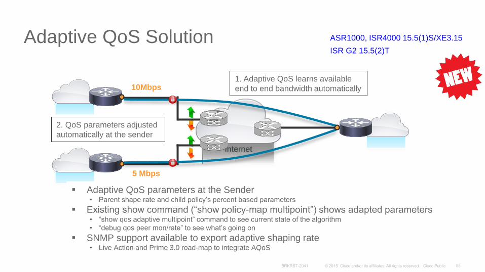
Adaptive QoS Solution
Internet
5 Mbps
10Mbps
Adaptive QoS parameters at the Sender• Parent shape rate and child policy’s percent based parameters
Existing show command (“show policy-map multipoint”) shows adapted parameters• “show qos adaptive multipoint” command to see current state of the algorithm
• “debug qos peer mon/rate” to see what’s going on
SNMP support available to export adaptive shaping rate• Live Action and Prime 3.0 road-map to integrate AQoS
1. Adaptive QoS learns available
end to end bandwidth automatically
2. QoS parameters adjusted
automatically at the sender
ASR1000, ISR4000 15.5(1)S/XE3.15
ISR G2 15.5(2)T
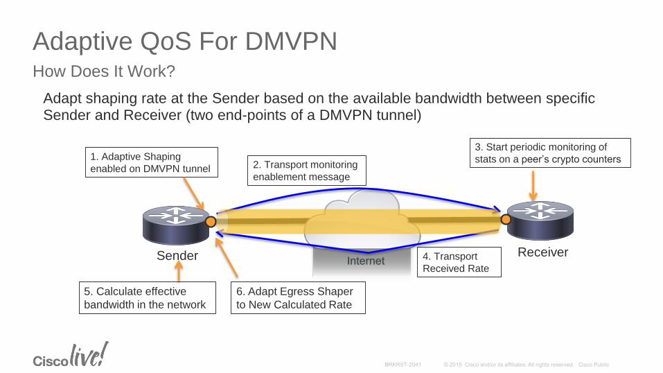
Adaptive QoS For DMVPNHow Does It Work?
Adapt shaping rate at the Sender based on the available bandwidth between specific Sender and Receiver (two end-points of a DMVPN tunnel)
Sender Receiver
1. Adaptive Shaping
enabled on DMVPN tunnel 2. Transport monitoring
enablement message
3. Start periodic monitoring of
stats on a peer’s crypto counters
4. Transport
Received Rate
5. Calculate effective
bandwidth in the network
Internet
6. Adapt Egress Shaper
to New Calculated Rate
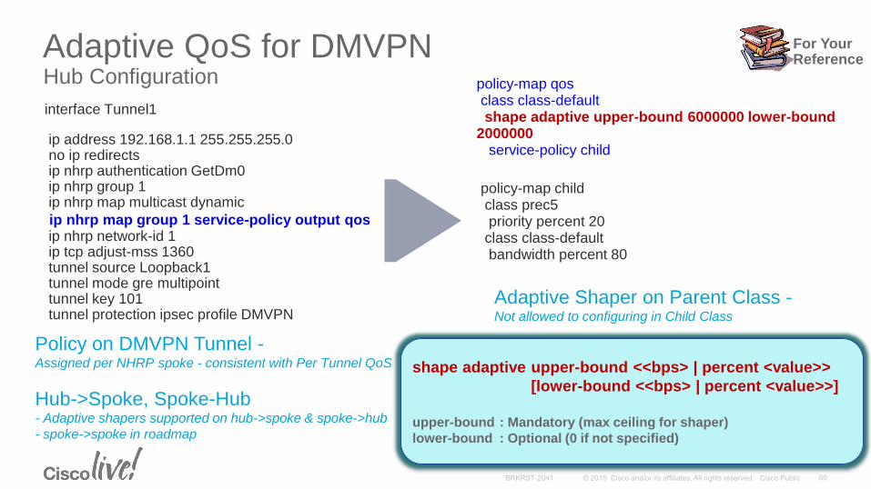
Adaptive QoS for DMVPNHub Configuration
interface Tunnel1
ip address 192.168.1.1 255.255.255.0no ip redirectsip nhrp authentication GetDm0ip nhrp group 1ip nhrp map multicast dynamic
ip nhrp map group 1 service-policy output qosip nhrp network-id 1ip tcp adjust-mss 1360tunnel source Loopback1tunnel mode gre multipointtunnel key 101tunnel protection ipsec profile DMVPN
policy-map qosclass class-defaultshape adaptive upper-bound 6000000 lower-bound
2000000service-policy child
policy-map childclass prec5priority percent 20
class class-defaultbandwidth percent 80
Policy on DMVPN Tunnel -Assigned per NHRP spoke - consistent with Per Tunnel QoS
Hub->Spoke, Spoke-Hub- Adaptive shapers supported on hub->spoke & spoke->hub
- spoke->spoke in roadmap
Adaptive Shaper on Parent Class -Not allowed to configuring in Child Class
shape adaptive upper-bound <<bps> | percent <value>>
[lower-bound <<bps> | percent <value>>]
upper-bound : Mandatory (max ceiling for shaper)
lower-bound : Optional (0 if not specified)
For YourReference

Adaptive QoS for DMVPNSpoke Configuration
interface Tunnel1ip address 192.168.1.2 255.255.255.0ip nhrp authentication GetDm0ip nhrp group 1ip nhrp map 192.168.1.1 11.1.1.1ip nhrp map multicast 11.1.1.1ip nhrp map group 1 service-policy output qosip nhrp network-id 1ip nhrp nhs 192.168.1.1ip nhrp hold-time 600ip tcp adjust-mss 1360tunnel source Loopback1tunnel mode gre multipointtunnel key 101tunnel protection ipsec profile DMVPN
policy-map qosclass class-defaultshape adaptive upper-bound 6000000 lower-bound
2000000 service-policy child
policy-map childclass class-defaultbandwidth percent 80
service-policy grand_child
policy-map grand_childclass class-default
Policy on DMVPN Tunnel -Assigned per NHRP spoke - consistent with Per Tunnel QoS
Hub->Spoke, Spoke-Hub- Adaptive shapers supported on hub->spoke & spoke->hub
- spoke->spoke in roadmap
shape adaptive upper-bound <<bps> | percent <value>>
[lower-bound <<bps> | percent <value>>]
upper-bound : Mandatory (max ceiling for shaper)
lower-bound : Optional (0 if not specified)
For YourReference

WAN Technologies & Solutions
• WAN Transport Technologies
• WAN Overlay Technologies
• WAN Optimization
• Wide Area Network Quality of Service
WAN Architecture Design Considerations
• WAN Design and Best Practices
• Secure WAN Communication with GETVPN
• Intelligent WAN Deployment
Summary
Agenda

Cisco Validate DesignMPLS WAN Technology Design Guide
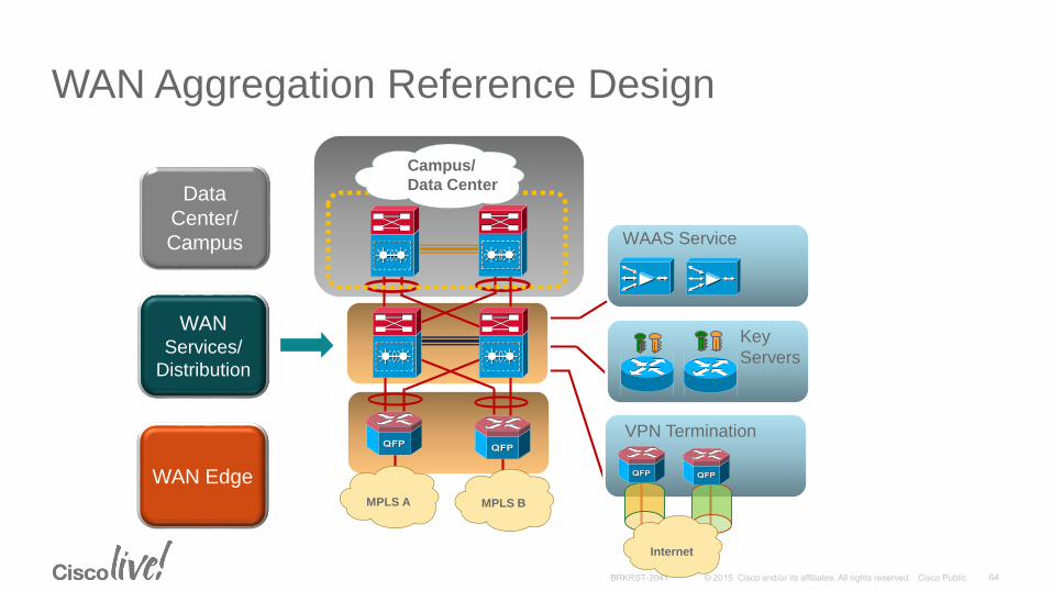
Data
Center/
Campus
WAN Services/
Distribution
WAN Aggregation Reference Design
MPLS A MPLS B
Campus/
Data Center
WAAS Service
Key
Servers
VPN Termination
Internet
WAN Edge
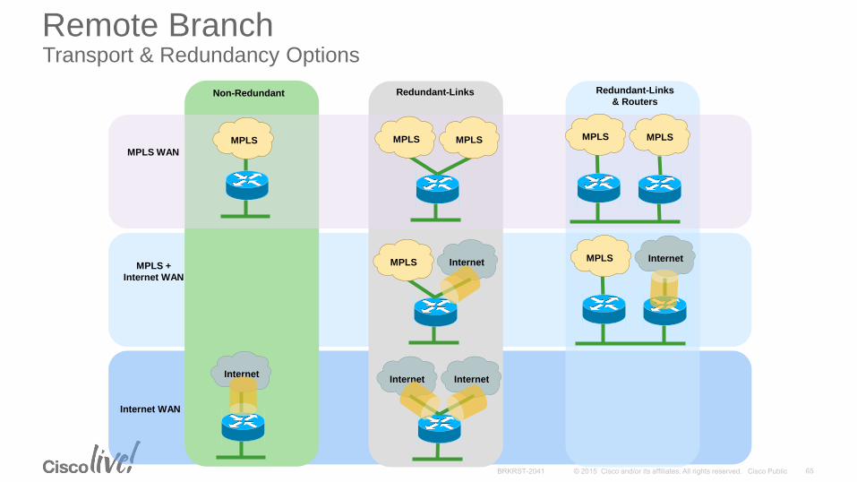
Remote Branch Transport & Redundancy Options
InternetInternet
InternetInternet
MPLS
MPLS WAN
MPLS +
Internet WAN
Internet
Internet WAN
MPLS MPLS MPLS MPLS
MPLS MPLS
Non-Redundant Redundant-Links Redundant-Links
& Routers
MPLS A MPLS B
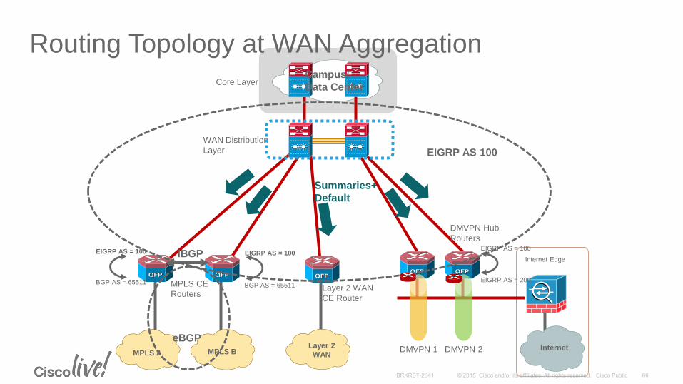
Routing Topology at WAN Aggregation
DMVPN Hub
Routers
Internet Edge
DMVPN 1 DMVPN 2
MPLS CE
RoutersLayer 2 WAN
CE Router
WAN Distribution
Layer
Core Layer
iBGP
eBGP
EIGRP AS 100
Summaries+
Default
Campus/
Data Center
Layer 2
WANInternet
BGP AS = 65511
EIGRP AS = 100
BGP AS = 65511
EIGRP AS = 100
EIGRP AS = 200
EIGRP AS = 100

WAN EdgeConnection Methods Compared
SiSi SiSi
P-to-P Link
Layer 3
VSS/3850Stacks
SiSi
LAN
Shared SiSi
Recommended
No Static Routes
No First Hop Redundancy Protocols
Multi-Chassis EtherChannel
WAN WANWAN
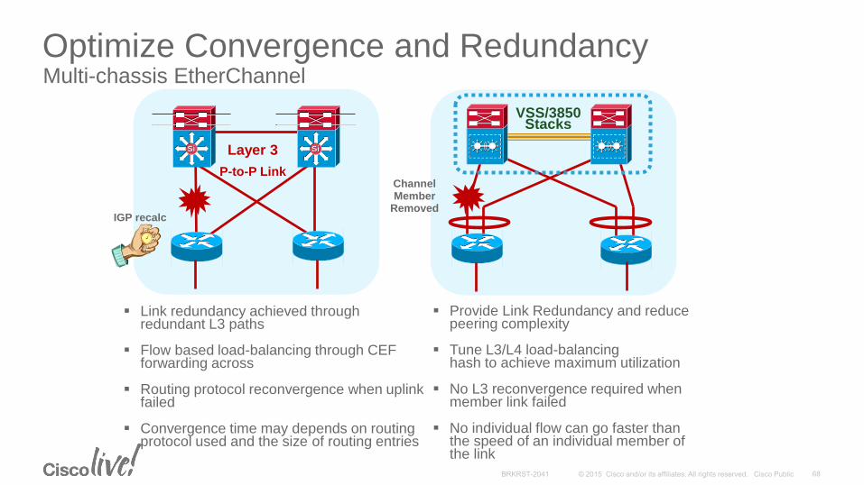
Optimize Convergence and RedundancyMulti-chassis EtherChannel
SiSi SiSi
P-to-P Link
Layer 3
Provide Link Redundancy and reduce peering complexity
Tune L3/L4 load-balancing hash to achieve maximum utilization
No L3 reconvergence required when member link failed
No individual flow can go faster than the speed of an individual member of the link
VSS/3850Stacks
IGP recalc
Channel Member
Removed
Link redundancy achieved through redundant L3 paths
Flow based load-balancing through CEFforwarding across
Routing protocol reconvergence when uplink failed
Convergence time may depends on routing protocol used and the size of routing entries
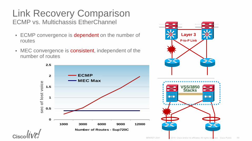
Link Recovery ComparisonECMP vs. Multichassis EtherChannel
ECMP convergence is dependent on the number of routes
MEC convergence is consistent, independent of the number of routes
0
0.5
1
1.5
2
2.5
1000 3000 6000 9000 12000
Number of Routes - Sup720C
ECMP
MEC Max
se
c o
f lo
st
vo
ice
SiSi SiSi
P-to-P Link
Layer 3
VSS/3850Stacks

Redundancy vs. Convergence TimeMore Is Not Always Better
2.5
0 10000
Se
co
nd
s
Routes
In principle, redundancy is easy
Any system with more parallel paths through the system will fail less often
The problem is a network isn’t really a single system but a group of interacting systems
Increasing parallel paths increases routing complexity, therefore increasing convergence times
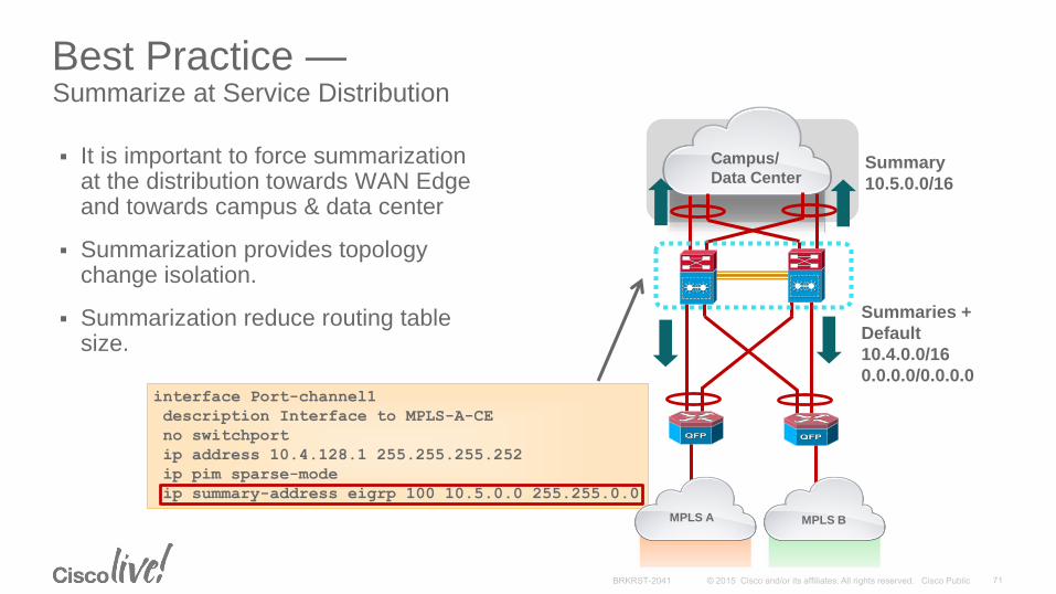
interface Port-channel1
description Interface to MPLS-A-CE
no switchport
ip address 10.4.128.1 255.255.255.252
ip pim sparse-mode
ip summary-address eigrp 100 10.5.0.0 255.255.0.0
Best Practice —Summarize at Service Distribution
It is important to force summarization at the distribution towards WAN Edge and towards campus & data center
Summarization provides topology change isolation.
Summarization reduce routing table size.
MPLS BMPLS A
Campus/
Data Center
Summaries +
Default
10.4.0.0/16
0.0.0.0/0.0.0.0
Summary
10.5.0.0/16
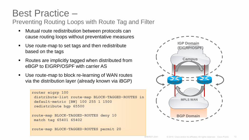
Best Practice –Preventing Routing Loops with Route Tag and Filter
MPLS WAN
Campus
BGP Domain
IGP Domain
(EIGRP/OSPF)
Mutual route redistribution between protocols can
cause routing loops without preventative measures
Use route-map to set tags and then redistribute
based on the tags
Routes are implicitly tagged when distributed from
eBGP to EIGRP/OSPF with carrier AS
Use route-map to block re-learning of WAN routes
via the distribution layer (already known via iBGP)
router eigrp 100
distribute-list route-map BLOCK-TAGGED-ROUTES in
default-metric [BW] 100 255 1 1500
redistribute bgp 65500
route-map BLOCK-TAGGED-ROUTES deny 10
match tag 65401 65402
route-map BLOCK-TAGGED-ROUTES permit 20
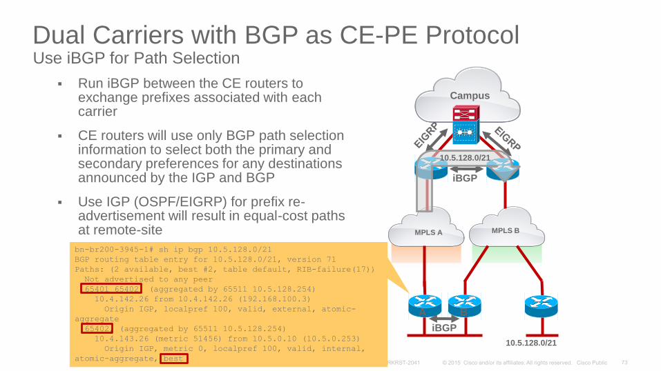
Dual Carriers with BGP as CE-PE ProtocolUse iBGP for Path Selection
Run iBGP between the CE routers to exchange prefixes associated with each carrier
CE routers will use only BGP path selection information to select both the primary and secondary preferences for any destinations announced by the IGP and BGP
Use IGP (OSPF/EIGRP) for prefix re-advertisement will result in equal-cost paths at remote-site
bn-br200-3945-1# sh ip bgp 10.5.128.0/21
BGP routing table entry for 10.5.128.0/21, version 71
Paths: (2 available, best #2, table default, RIB-failure(17))
Not advertised to any peer
65401 65402, (aggregated by 65511 10.5.128.254)
10.4.142.26 from 10.4.142.26 (192.168.100.3)
Origin IGP, localpref 100, valid, external, atomic-
aggregate
65402, (aggregated by 65511 10.5.128.254)
10.4.143.26 (metric 51456) from 10.5.0.10 (10.5.0.253)
Origin IGP, metric 0, localpref 100, valid, internal,
atomic-aggregate, best
MPLS B
Campus
iBGP
MPLS A
iBGP
10.5.128.0/21
10.5.128.0/21
A B

Campus
MPLS BMPLS A
Best Practice - Implement AS-Path FilterPrevent Branch Site Becoming Transit Network
Dual carrier sites can unintentionally become transit network during network failure event and causing network congestion due to transit traffic
Design the network so that transit path between two carriers only occurs at sites with enough bandwidth
Implement AS-Path filter to allow only locally originated routes to be advertised on the outbound updates for branches that should not be transit
router bgp 65511
neighbor 10.4.142.26 route-map NO-TRANSIT-AS out
!
ip as-path access-list 10 permit ^$
!
route-map NO-TRANSIT-AS permit 10
match as-path 10
iBGP
A B
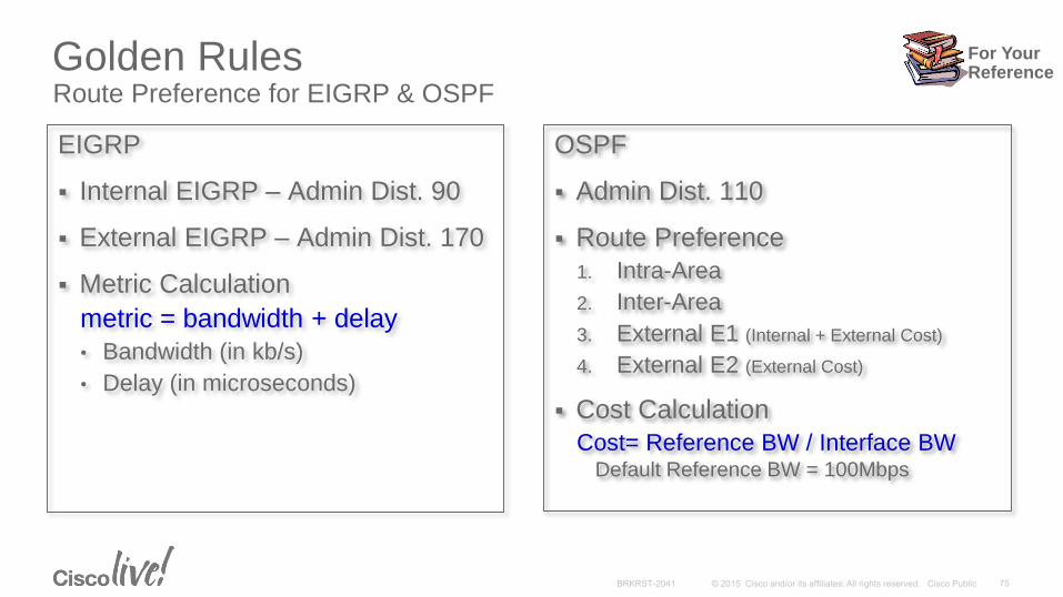
Golden RulesRoute Preference for EIGRP & OSPF
EIGRP
Internal EIGRP – Admin Dist. 90
External EIGRP – Admin Dist. 170
Metric Calculation
metric = bandwidth + delay
• Bandwidth (in kb/s)
• Delay (in microseconds)
OSPF
Admin Dist. 110
Route Preference
1. Intra-Area
2. Inter-Area
3. External E1 (Internal + External Cost)
4. External E2 (External Cost)
Cost Calculation
Cost= Reference BW / Interface BWDefault Reference BW = 100Mbps
For YourReference
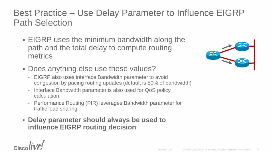
Best Practice – Use Delay Parameter to Influence EIGRPPath Selection
EIGRP uses the minimum bandwidth along the path and the total delay to compute routing metrics
Does anything else use these values?• EIGRP also uses interface Bandwidth parameter to avoid
congestion by pacing routing updates (default is 50% of bandwidth)
• Interface Bandwidth parameter is also used for QoS policy calculation
• Performance Routing (PfR) leverages Bandwidth parameter for traffic load sharing
Delay parameter should always be used to influence EIGRP routing decision

Campus
MPLS + Internet WANPrefer the MPLS Path over Internet
EIGRP
AS100
10.4.128.2
10.5.48.0/21
EIGRP
AS100
eBGP routes are redistributed into EIGRP 100 as
external routes with default Admin Distance 170
Running same EIGRP AS for both campus and
DMVPN network would result in Internet path preferred
over MPLS path
Internet
eB
GP
MPLS A
Campus
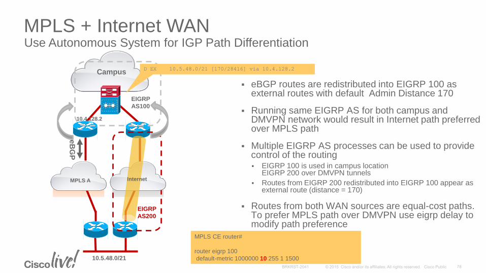
MPLS + Internet WANUse Autonomous System for IGP Path Differentiation
eBGP routes are redistributed into EIGRP 100 as external routes with default Admin Distance 170
Running same EIGRP AS for both campus and DMVPN network would result in Internet path preferred over MPLS path
Multiple EIGRP AS processes can be used to provide control of the routing EIGRP 100 is used in campus location
EIGRP 200 over DMVPN tunnels
Routes from EIGRP 200 redistributed into EIGRP 100 appear as external route (distance = 170)
Routes from both WAN sources are equal-cost paths. To prefer MPLS path over DMVPN use eigrp delay to modify path preference
EIGRP
AS100
EIGRP
AS200
D EX 10.5.48.0/21 [170/28416] via 10.4.128.2
10.4.128.2
eB
GP
10.5.48.0/21
MPLS CE router#
router eigrp 100
default-metric 1000000 10 255 1 1500
MPLS A Internet
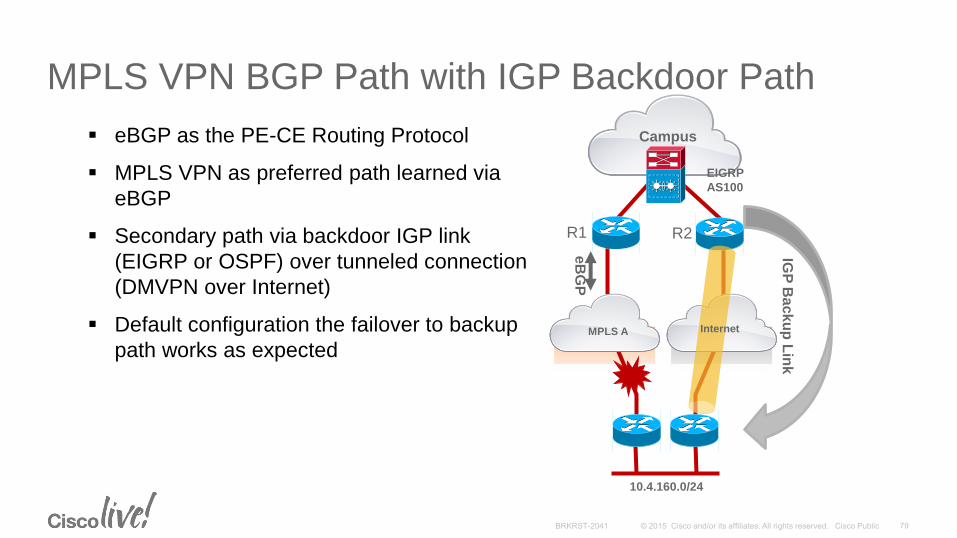
Campus
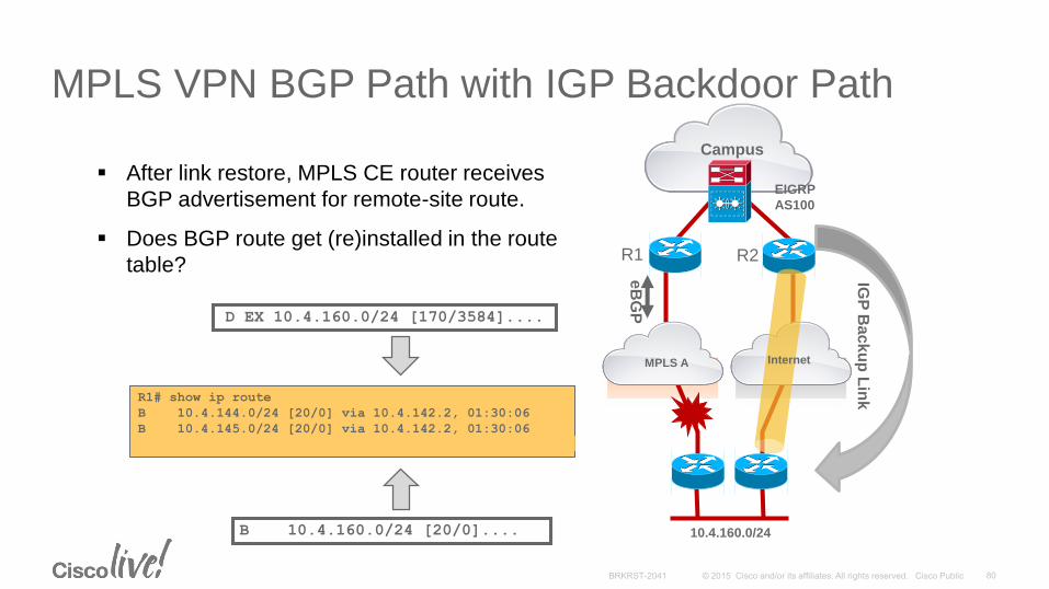
MPLS VPN BGP Path with IGP Backdoor Path
eBGP as the PE-CE Routing Protocol
MPLS VPN as preferred path learned via
eBGP
Secondary path via backdoor IGP link
(EIGRP or OSPF) over tunneled connection
(DMVPN over Internet)
Default configuration the failover to backup
path works as expected
EIGRP
AS100
eB
GP
10.4.160.0/24
IGP
Ba
ck
up
Lin
k
R1 R2
MPLS A Internet
Campus
MPLS VPN BGP Path with IGP Backdoor Path
EIGRP
AS100
eB
GP
10.4.160.0/24
R1 R2
IGP
Ba
ck
up
Lin
k
D EX 10.4.160.0/24 [170/3584]....
B 10.4.160.0/24 [20/0]....
R1# show ip route
B 10.4.144.0/24 [20/0] via 10.4.142.2, 01:30:06
B 10.4.145.0/24 [20/0] via 10.4.142.2, 01:30:06
D EX 10.4.160.0/24 [170/3584] via 10.4.128.9, 00:30:06
After link restore, MPLS CE router receives
BGP advertisement for remote-site route.
Does BGP route get (re)installed in the route
table?
MPLS A Internet
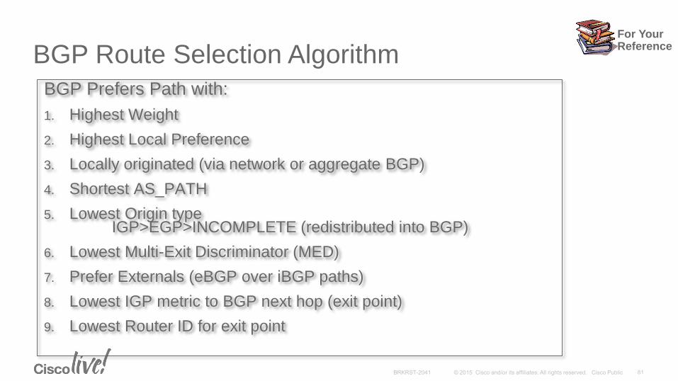
BGP Route Selection Algorithm
BGP Prefers Path with:
1. Highest Weight
2. Highest Local Preference
3. Locally originated (via network or aggregate BGP)
4. Shortest AS_PATH
5. Lowest Origin typeIGP>EGP>INCOMPLETE (redistributed into BGP)
6. Lowest Multi-Exit Discriminator (MED)
7. Prefer Externals (eBGP over iBGP paths)
8. Lowest IGP metric to BGP next hop (exit point)
9. Lowest Router ID for exit point
For YourReference
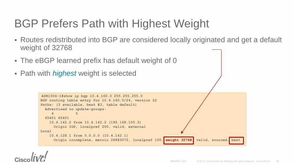
ASR1004-1#show ip bgp 10.4.160.0 255.255.255.0
BGP routing table entry for 10.4.160.0/24, version 22
Paths: (3 available, best #3, table default)
Advertised to update-groups:
4 5
65401 65401
10.4.142.2 from 10.4.142.2 (192.168.100.3)
Origin IGP, localpref 200, valid, external
Local
10.4.128.1 from 0.0.0.0 (10.4.142.1)
Origin incomplete, metric 26883072, localpref 100, weight 32768, valid, sourced, best
BGP Prefers Path with Highest Weight
Routes redistributed into BGP are considered locally originated and get a default weight of 32768
The eBGP learned prefix has default weight of 0
Path with highest weight is selected

ASR1004-1#show ip bgp 10.4.160.0 255.255.255.0
BGP routing table entry for 10.4.160.0/24, version 22
Paths: (1 available, best #1, table default)
Not advertised to any peer
65401 65401
10.4.142.2 from 10.4.142.2 (192.168.100.3)
Origin IGP, metric 0, localpref 100, weight 35000, valid, external, best
Prefer the eBGP Path over IGPSet the eBGP weight > 32768
To resolve this issue set the weights on route learned via eBGP peer higher than 32768
neighbor 10.4.142.2 weight 35000
ASR1004-1#show ip route
....
B 10.4.160.0/24 [20/0] via 10.4.142.2, 05:00:06
WAN Technologies & Solutions
• WAN Transport Technologies
• WAN Overlay Technologies
• WAN Optimization
• Wide Area Network Quality of Service
WAN Architecture Design Considerations
• WAN Design and Best Practices
• Secure WAN Communication with GETVPN
• Intelligent WAN Deployment
Summary
Agenda
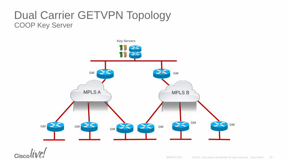
Dual Carrier GETVPN TopologyCOOP Key Server
Key Servers
MPLS BMPLS A
GMGM
GM GMGM
GMGM
GM
MPLS A MPLS B

Best Practice - High Availability with Cooperative Key Servers
Two or more KSs known as COOP KSs manage a common set of keys and security policies for GETVPN group members
Group members can register to any one of the available KSs
Cooperative KSs periodically exchange and synchronize group’s database, policy and keys
Primary KS is responsible to generate and distribute group keys
GM 1
GM 3
Subnet 1
Subnet 4
Subnet 2
Subnet 3
GM 4
GM 2
Cooperative KS1
IP Network
Cooperative KS2

Best Practice - Key Server Recommendations Maintain reliable KS communication:
•Insure multiple routing paths exist between all KS
•Use loopback interface for KS registration and Cooperative KS protocol Use IKE keep-alive for KS-KS communication
Use only globally applicable policies in KS proxy identifiers:
•Site specific policies should be applied at the GM
•Goal is to create symmetric policies on KS
•Exception policy development should be done on GM, not KS
Use sufficiently long key lifetimes to minimize key transitions:
•Traffic Encryption Key (TEK) > 3600 sec
•Key Encryption Key (KEK) > 86400 sec
Insure rekey interval extends longer than routing convergence time
For YourReference
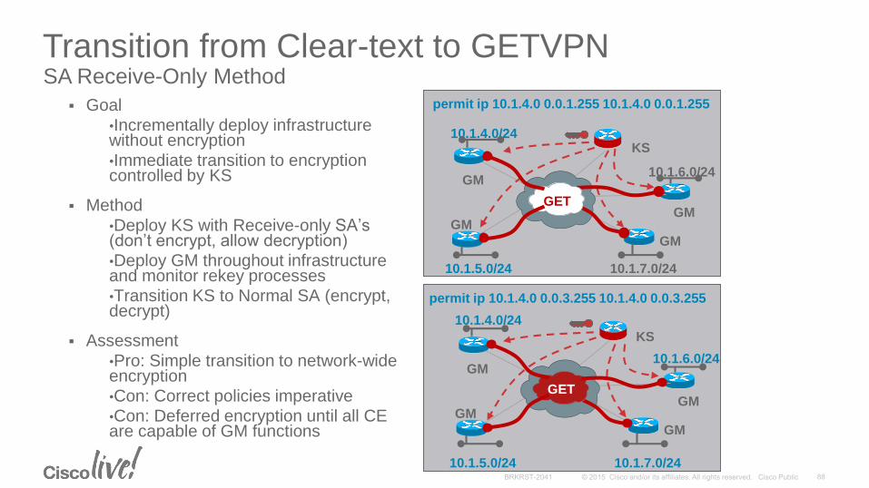
Transition from Clear-text to GETVPNSA Receive-Only Method
Goal
•Incrementally deploy infrastructure without encryption
•Immediate transition to encryption controlled by KS
Method
•Deploy KS with Receive-only SA’s(don’t encrypt, allow decryption)
•Deploy GM throughout infrastructure and monitor rekey processes
•Transition KS to Normal SA (encrypt, decrypt)
Assessment
•Pro: Simple transition to network-wide encryption
•Con: Correct policies imperative
•Con: Deferred encryption until all CE are capable of GM functions
permit ip 10.1.4.0 0.0.3.255 10.1.4.0 0.0.3.255
GM
GMGM
GM
KS10.1.4.0/24
10.1.6.0/24
10.1.5.0/24 10.1.7.0/24
GM
GMGM
GM
GET
KS
10.1.4.0/24
10.1.6.0/24
10.1.5.0/24 10.1.7.0/24
permit ip 10.1.4.0 0.0.1.255 10.1.4.0 0.0.1.255
GET
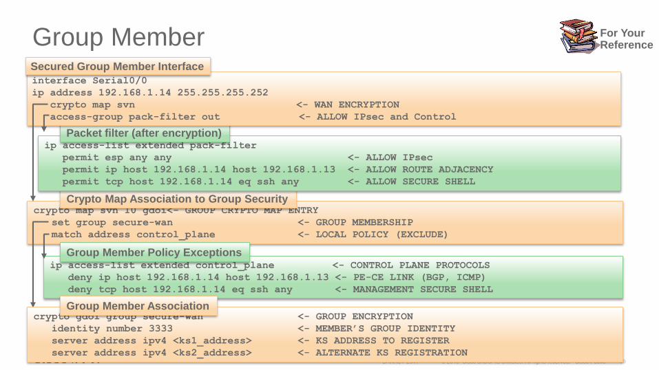
Group Member
crypto map svn 10 gdoi<- GROUP CRYPTO MAP ENTRY
set group secure-wan <- GROUP MEMBERSHIP
match address control_plane <- LOCAL POLICY (EXCLUDE)
Crypto Map Association to Group Security
ip access-list extended control_plane <- CONTROL PLANE PROTOCOLS
deny ip host 192.168.1.14 host 192.168.1.13 <- PE-CE LINK (BGP, ICMP)
deny tcp host 192.168.1.14 eq ssh any <- MANAGEMENT SECURE SHELL
Group Member Policy Exceptions
ip access-list extended pack-filter
permit esp any any <- ALLOW IPsec
permit ip host 192.168.1.14 host 192.168.1.13 <- ALLOW ROUTE ADJACENCY
permit tcp host 192.168.1.14 eq ssh any <- ALLOW SECURE SHELL
Packet filter (after encryption)
crypto gdoi group secure-wan <- GROUP ENCRYPTION
identity number 3333 <- MEMBER’S GROUP IDENTITY
server address ipv4 <ks1_address> <- KS ADDRESS TO REGISTER
server address ipv4 <ks2_address> <- ALTERNATE KS REGISTRATION
Group Member Association
interface Serial0/0
ip address 192.168.1.14 255.255.255.252
crypto map svn <- WAN ENCRYPTION
access-group pack-filter out <- ALLOW IPsec and Control
Secured Group Member Interface
For YourReference
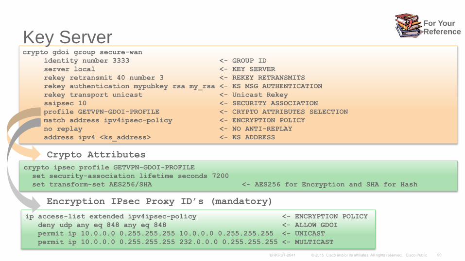
crypto gdoi group secure-wan
identity number 3333 <- GROUP ID
server local <- KEY SERVER
rekey retransmit 40 number 3 <- REKEY RETRANSMITS
rekey authentication mypubkey rsa my_rsa <- KS MSG AUTHENTICATION
rekey transport unicast <- Unicast Rekey
saipsec 10 <- SECURITY ASSOCIATION
profile GETVPN-GDOI-PROFILE <- CRYPTO ATTRIBUTES SELECTION
match address ipv4ipsec-policy <- ENCRYPTION POLICY
no replay <- NO ANTI-REPLAY
address ipv4 <ks_address> <- KS ADDRESS
Key Server
crypto ipsec profile GETVPN-GDOI-PROFILE
set security-association lifetime seconds 7200
set transform-set AES256/SHA <- AES256 for Encryption and SHA for Hash
Crypto Attributes
ip access-list extended ipv4ipsec-policy <- ENCRYPTION POLICY
deny udp any eq 848 any eq 848 <- ALLOW GDOI
permit ip 10.0.0.0 0.255.255.255 10.0.0.0 0.255.255.255 <- UNICAST
permit ip 10.0.0.0 0.255.255.255 232.0.0.0 0.255.255.255 <- MULTICAST
Encryption IPsec Proxy ID’s (mandatory)
For YourReference
WAN Technologies & Solutions
• WAN Transport Technologies
• WAN Overlay Technologies
• WAN Optimization
• Wide Area Network Quality of Service
WAN Architecture Design Considerations
• WAN Design and Best Practices
• Secure WAN Communication with GETVPN
• Intelligent WAN Deployment
Summary
Agenda
Internet Becoming an Extension of Enterprise WAN
Commodity Transports Viable Now
Dramatic Bandwidth, Price Performance Benefits
Higher Network Availability
Improved Performance Over Internet
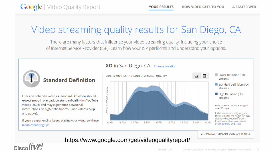
https://www.google.com/get/videoqualityreport/
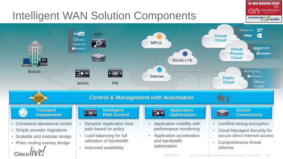
Intelligent WAN Solution Components
MPLS
Branch
3G/4G-LTE
AVC
Internet
PrivateCloud
VirtualPrivateCloud
PublicCloudWAAS PfR
Application Optimization
• Application visibility with
performance monitoring
• Application acceleration
and bandwidth
optimization
Secure Connectivity
• Certified strong encryption
• Cloud Managed Security for
secure direct Internet access
• Comprehensive threat
defense
Intelligent Path Control
• Dynamic Application best
path based on policy
• Load balancing for full
utilization of bandwidth
• Improved availability
TransportIndependent
• Consistent operational model
• Simple provider migrations
• Scalable and modular design
• IPsec routing overlay design
Control & Management with Automation

Hybrid WAN DesignsTraditional and IWAN
Internet MPLS
Branch
DMVPN GETVPN
Internet MPLS
Branch
DMVPN DMVPN
Two IPsec TechnologiesGETVPN/MPLS
DMVPN/Internet
Two WAN Routing
DomainsMPLS: eBGP or Static
Internet: iBGP, EIGRP or OSPF
Route Redistribution
Route Filtering Loop Prevention
Active/Standby
WAN PathsPrimary With Backup
One IPsec OverlayDMVPN
One WAN
Routing DomainiBGP, EIGRP, or OSPF
Minimal route filtering
Active/Active
WAN Paths
ISR-G2
ASR 1000 ASR 1000
ISP A SP V
ISR-G2
ISP A SP V
ASR 1000 ASR 1000
TRADITIONAL HYBRID
Data Center
IWAN HYBRID
Data Center

DMVPN Deployment over InternetMultiple Default Routes for VPN Headend
VPN Headend has a default route to ASAfirewall’s VPN-DMZ interface to reach Internet
Remote site policy requires centralized Internet access
Enable EIGRP between VPN headend & Campus core to propagate default to remote
Static default (admin dist=0) remains active,
VPN-DMZ is wrong firewall interface for user traffic
Adjust admin distance so EIGRP route installed (to core)
VPN tunnel drops
VPN-DMZ
Internet Edge
Block
default
default
INSIDE
OUTSIDE
default
Internet
default
default
Internet
Internet
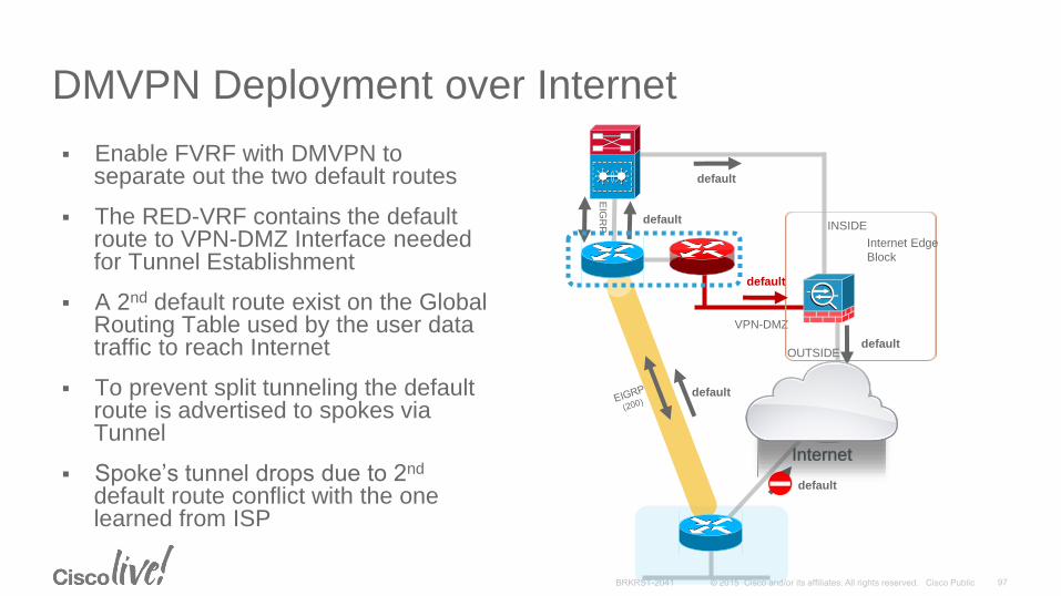
DMVPN Deployment over Internet
Enable FVRF with DMVPN to separate out the two default routes
The RED-VRF contains the default route to VPN-DMZ Interface needed for Tunnel Establishment
A 2nd default route exist on the Global Routing Table used by the user data traffic to reach Internet
To prevent split tunneling the default route is advertised to spokes via Tunnel
Spoke’s tunnel drops due to 2nd
default route conflict with the one learned from ISP
VPN-DMZ
Internet Edge
Block
default
default
INSIDE
OUTSIDE
EIG
RP default
Internet
default
default
default
Internet
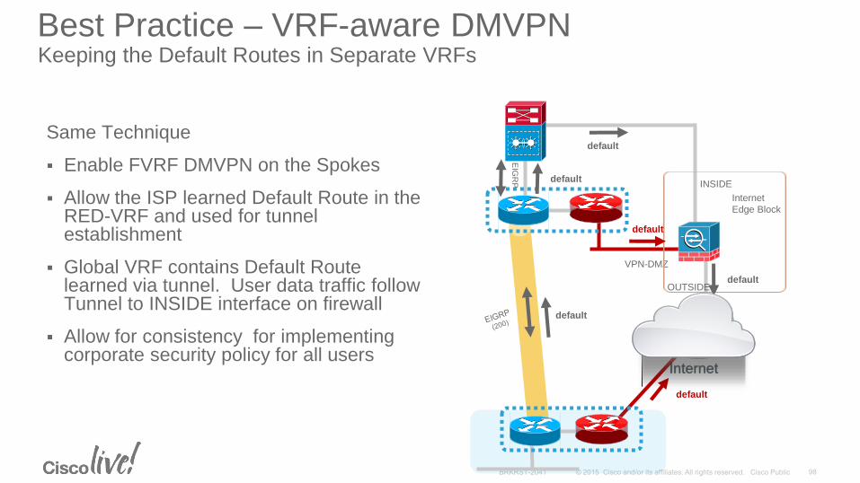
Best Practice – VRF-aware DMVPNKeeping the Default Routes in Separate VRFs
Same Technique
Enable FVRF DMVPN on the Spokes
Allow the ISP learned Default Route in the RED-VRF and used for tunnel establishment
Global VRF contains Default Route learned via tunnel. User data traffic follow Tunnel to INSIDE interface on firewall
Allow for consistency for implementing corporate security policy for all users
Internet
VPN-DMZ
Internet
Edge Block
default
default
INSIDE
OUTSIDEdefault
default
default
EIG
RP default
Internet
Internet
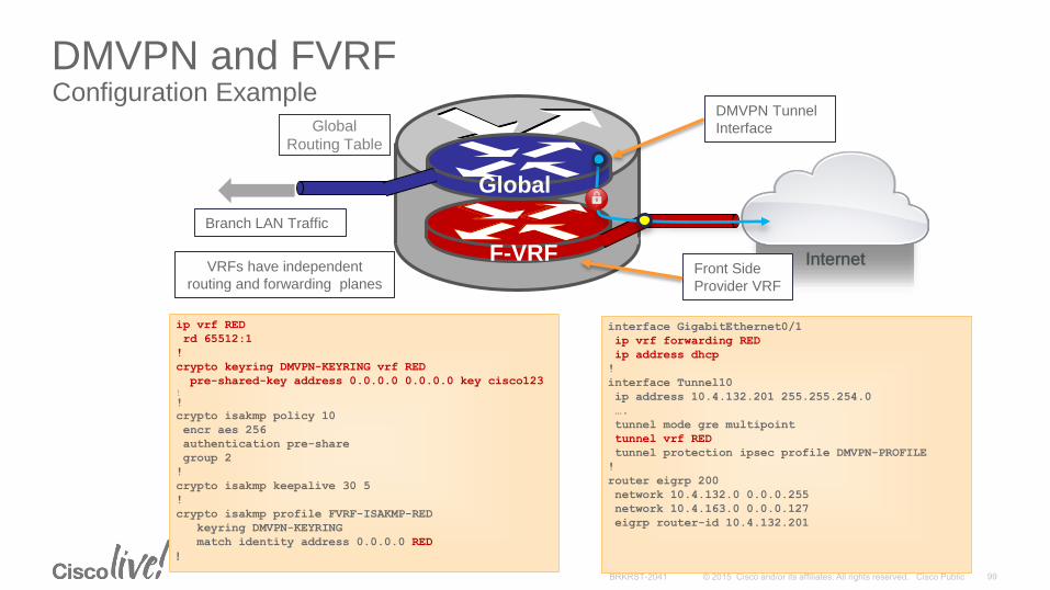
DMVPN and FVRFConfiguration Example
ip vrf RED
rd 65512:1
!
crypto keyring DMVPN-KEYRING vrf RED
pre-shared-key address 0.0.0.0 0.0.0.0 key cisco123!
!
crypto isakmp policy 10
encr aes 256
authentication pre-share
group 2
!
crypto isakmp keepalive 30 5
!
crypto isakmp profile FVRF-ISAKMP-RED
keyring DMVPN-KEYRING
match identity address 0.0.0.0 RED
!
interface GigabitEthernet0/1
ip vrf forwarding RED
ip address dhcp
!
interface Tunnel10
ip address 10.4.132.201 255.255.254.0
….
tunnel mode gre multipoint
tunnel vrf RED
tunnel protection ipsec profile DMVPN-PROFILE
!
router eigrp 200
network 10.4.132.0 0.0.0.255
network 10.4.163.0 0.0.0.127
eigrp router-id 10.4.132.201
Global
F-VRF
Branch LAN Traffic
Front Side
Provider VRF
VRFs have independent
routing and forwarding planes
DMVPN Tunnel
InterfaceGlobal
Routing Table
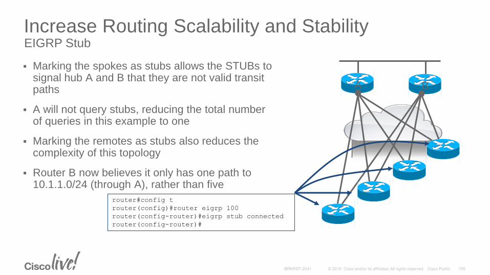
Increase Routing Scalability and StabilityEIGRP Stub
Marking the spokes as stubs allows the STUBs to signal hub A and B that they are not valid transit paths
A will not query stubs, reducing the total number of queries in this example to one
Marking the remotes as stubs also reduces the complexity of this topology
Router B now believes it only has one path to 10.1.1.0/24 (through A), rather than five
BA
router#config t
router(config)#router eigrp 100
router(config-router)#eigrp stub connected
router(config-router)#
A B

Dual Router Spoke DesignRouting Leaking thru STUBs
EIGRP Hub and Spoke Stub Route Leaking
EIGRP offers additional control over routes advertised by Stubs
Some deployments have a single remote site with tworouters and we want to mark the entire siteas a “stub site”
Normally stubs C and D won’t advertise learned routesto each other, to override this, add the “leak-map” configuration
0.0.0.0/0 0.0.0.0/0
No Advertisementsroute-map LeakList permit 10
match ip address 1
match interface e0/0
route-map LeakList permit 20
match ip address 2
match interface e1/0
!
access-list 1 permit 10.1.1.0
access-list 2 permit 0.0.0.0
!
router eigrp IWAN
address-family ipv4 autonomous-system 100
eigrp stub leak-map LeakList
10.1.1.0/24
Remote Site
A B
C D
A B
C D

Best Practices —Avoid Fragmentation with IPSec VPN
IP fragmentation will cause CPU and memory overhead and resulting in lowering throughput performance
When one fragment of a datagram is dropped, the entire original IP datagram will have to be resent
Use ‘mode transport’ on transform-set• NHRP needs for NAT support and saves 20 bytes
Avoid MTU issues with the following best practices• ip mtu 1400
• ip tcp adjust-mss 1360
MTU 1500MTU 1500MTU 1400
Tunnel Setting (AES256+SHA) Minimum MTU Recommended MTU
GRE/IPSec (Tunnel Mode) 1414 bytes 1400 bytes
GRE/IPSec (Transport Mode) 1434 bytes 1400 bytes
GRE+IPsec
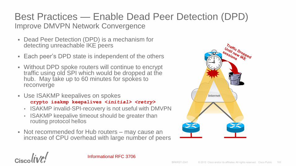
Best Practices — Enable Dead Peer Detection (DPD)Improve DMVPN Network Convergence
Dead Peer Detection (DPD) is a mechanism for detecting unreachable IKE peers
Each peer’s DPD state is independent of the others
Without DPD spoke routers will continue to encrypt traffic using old SPI which would be dropped at the hub. May take up to 60 minutes for spokes to reconverge
Use ISAKMP keepalives on spokescrypto isakmp keepalives <initial> <retry>
• ISAKMP invalid-SPI-recovery is not useful with DMVPN
• ISAKMP keepalive timeout should be greater than routing protocol hellos
Not recommended for Hub routers – may cause an increase of CPU overhead with large number of peers
Internet
tun10
Informational RFC 3706

Internet
DMVPN Internet Deployment Dynamic IP Address Assignment on the Spokes
Spokes are receiving dynamic address assignment from the ISP
Spoke reboots and receive a new IP address from the ISP, VPN session is established but no traffic passes
Following error message appears on the spoke
Hub router (NHS) reject registration attempts for the same private address that uses a different NBMA address
To resolve this issue, configure following command on spoke routers –ip nhrp registration no-unique
"%NHRP-3-PAKREPLY: Receive Registration
Reply packet with error - unique address
registered already(14)"
Internet
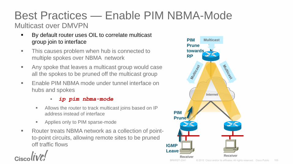
Best Practices — Enable PIM NBMA-ModeMulticast over DMVPN
Receiver Receiver
IGMP
Leave
PIM
Prune
PIM
Prune
towards
RP
Multicast By default router uses OIL to correlate multicast
group join to interface
This causes problem when hub is connected to
multiple spokes over NBMA network
Any spoke that leaves a multicast group would case
all the spokes to be pruned off the multicast group
Enable PIM NBMA mode under tunnel interface on
hubs and spokes
ip pim nbma-mode
Allows the router to track multicast joins based on IP
address instead of interface
Applies only to PIM sparse-mode
Router treats NBMA network as a collection of point-
to-point circuits, allowing remote sites to be pruned
off traffic flows

IWAN Transport Best Practices
Private peering with Internet providers• Use same Internet provider for hub and spoke sites
• Avoids Internet Exchange bottlenecks between providers
• Reduces round trip latency
DMVPN Phase 3• Separate DMVPN network per provider for path diversity
• Per tunnel QOS
• NG Encryption – IKEv2 + AES-GCM-256 encryption
Transport settings• Use the same MTU size on all WAN paths
• Bandwidth settings should match offered rate
Routing overlay• iBGP or EIGRP for high scale (1000+ sites)
• Single routing process, simplified operations
• Front-side VRF to isolate external interfaces
Branch
Internet MPLS
DMVPNPurple
DMVPNGreen
IWAN HYBRID
Data Center
ISP A SP V
106

WAN Technologies & Solutions
• WAN Transport Technologies
• WAN Overlay Technologies
• WAN Optimization
• Wide Area Network Quality of Service
WAN Architecture Design Considerations
• WAN Design and Best Practices
• Secure WAN Communication with GETVPN
• Intelligent WAN Deployment
Summary
Agenda
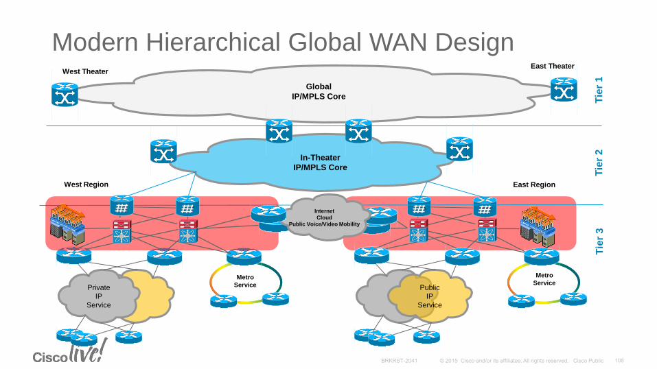
East Region
Tie
r 3
Public
IP
Service
Metro
Service
Modern Hierarchical Global WAN Design
Tie
r 1
Tie
r 2
Global
IP/MPLS Core
West TheaterEast Theater
In-Theater
IP/MPLS Core
Private
IP
Service
Metro
Service
West Region
Internet
Cloud
Public Voice/Video Mobility

Key Takeaways
Understand how WAN characteristics can affect your applications.
• Bandwidth, latency, loss
A modular hierarchical network infrastructure is the foundation for a solid WAN architecture. Good WAN design have many well-utilized component
Encryption is a foundation component of all WAN designs and can be deployed transparently.
Understand how to build wide area network leveraging Internet transport with Intelligent WAN.
Design a network with consistent behavior that provides predictable performance.
More is not always better. Keep it simple!
Suggested Sessions
BRKRST-2309 Introduction to WAN MACsec
BRKRST-3336 WAN Virtualization using OTP
BRKRST-2514 Application Optimization and Provisioning the IWAN
BRKCRS-2000 Intelligent WAN 2.0 Update
BRKRST-3045 LISP A Next Generation Networking Architecture

Complete Your Online Session Evaluation
Don’t forget: Cisco Live sessions will be available for viewing on-demand after the event at CiscoLive.com/Online
• Give us your feedback to be entered into a Daily Survey Drawing. A daily winner will receive a $750 Amazon gift card.
• Complete your session surveys though the Cisco Live mobile app or your computer on Cisco Live Connect.
Continue Your Education
• Demos in the Cisco campus
• Walk-in Self-Paced Labs
• Table Topics
• Meet the Engineer 1:1 meetings
• Related sessions

Thank you