Embed Size (px)
Citation preview
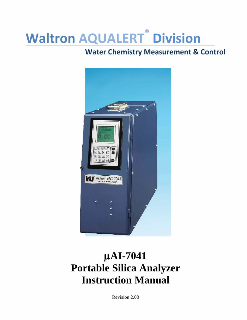
Revision 2.08
Waltron AQUALERT® Division Water Chemistry Measurement & Control
AI-7041
Portable Silica Analyzer
Instruction Manual
AI-7041
- 2 -
WALTRON CUSTOMER COMMITMENT
This instruction manual is a technical guide to aid the customer in the set-up, operation, and
maintenance of their new Waltron measuring system. Waltron provides continuous product
mprovement and reserves the right to make any modifications to the information contained herein
without notice.
Copyright © Waltron Bull & Roberts, LLC, 2014
All Rights Reserved
Technical questions concerning this product should be addressed to:
Waltron Technical Service Department
Whitehouse, New Jersey
Phone: (800)-242-7353
Fax: (908)-534-5546
www.waltron.net
Please be ready to provide the following information:
Date analyzer was purchased
Analyzer model and serial number
Recent maintenance history
Calibration slope values and detailed description of problem
Waltron’s technical expertise and extensive experience provides personalized solutions to the water
quality industry. It is Waltron’s commitment to provide the customer with timely and accurate
technical service and support.
Waltron fully expects the customer to be satisfied with the quality, performance, and cost of this
product.
If there are any questions or concerns regarding this product, please feel free to contact Waltron at
(800)-242-7353.
Thank you for choosing Waltron!
Please note the Waltron mailing and shipping address:
Via Mail:
Waltron Bull & Roberts, LLC
50 Tannery Road, P.O. Box 70
Whitehouse, NJ 08888
Via UPS/FED-EX/Motor Carrier:
Waltron Bull & Roberts, LLC
50 Tannery Road
Somerville, NJ 08876
AI-7041
- 3 -
SAFETY
Please observe proper safety and handling precautions when installing, operating, maintaining, and
servicing this product. The following should be noted and adhered to:
Read and understand manual before working with analyzer.
Pay special attention to warning labels on enclosures, containers, packages and chemicals.
Only qualified personnel should be involved in the installation, operation, and servicing of the
analyzer.
Follow safety precautions when operating analyzer in conditions of high pressure and/or
temperature.
Keep analyzer chemicals away from heat and extreme temperatures. Reagent powders must be
kept dry.
Follow all regulations and warning labels when disposing of chemicals. Do not mix chemicals.
To obtain analyzer safety information or Material Safety Data Sheets (MSDS), please contact Waltron
or logon to www.waltron.net .
AI-7041
- 4 -
WARRANTY AGREEMENT
If, within one year from the date of shipment, the customer experiences any equipment defects or is not
satisfied with the analyzer manufacturing, Waltron will repair, or at its option, replace any defective
part(s) free of charge. This warranty requires that the defective part(s) be returned to Waltron with
shipping charges prepaid.
At Waltron discretion, a Technical Service Specialist may be sent out to repair or replace the defective
part(s) on location. Traveling time and expenses of the Technical Service Specialist is at the customer’s
expense.
Equipment sent to Waltron must be appropriately packaged and the following information must be
provided prior to returning to Waltron:
The Return Authorization (RA) number assigned to the customer by the Waltron Technical
Service Department
Customer name, address and department
Name and telephone number of the individual responsible for returning items for repair
Brief problem description
Ship to Waltron service center:
Via Mail:
Waltron Bull & Roberts, LLC
50 Tannery Road, P.O. Box 70
Whitehouse, NJ 08888
Via UPS/FED-EX/Motor Carrier:
Waltron Bull & Roberts, LLC
50 Tannery Road
Somerville, NJ 08876
The Waltron Warranty Agreement:
Covers expendable sensors for one month after shipment and reusable electrodes for six months
after shipment.
Does not apply to damages occurred during shipping.
Warranty will be nullified if goods have been used for purposes other than those for which they
are intended or if any seal has been removed, broken or tampered with or if the Waltron
trademark or serial number has be removed, defaced, or altered.
Does not cover expendable supply items such as reagents, tubing and electrolytes.
Does not cover misuse or mistreatment by the user.
Does not cover previous repair or alteration by unauthorized individuals.
Waltron does not assume responsibility for contingent liability through alleged failure or failures of
products or product accessories.
AI-7041
- 5 -
CHECKLIST OF MATERIALS
In order to ensure customer satisfaction, Waltron does its best to provide adequate and timely
packaging and shipping services. Please perform the following after receiving a shipment:
Inspect all shipping containers upon receipt and record any visible damage. If there are any
outward signs of damage, please retain all containers and packages for inspection by carrier.
Please retain all packing material so that it can be used for future moving and shipping needs.
Check all items received against those on the packing list. Chemicals are usually shipped in a
separate package and will be itemized accordingly.
Verify that the number of packages received agrees with the packing list and shipping papers.
Notify both Waltron and the carrier if any problems occur.
Important Notice:
All analyzers are inspected and tested prior to shipment.
In normal use, the unit should require only minor maintenance and should operate correctly and
without fault over a long period of time.
Please note that if electronic components need to be replaced, it may be necessary to adjust
and/or calibrate the analyzer.
Failure to carry out correct maintenance procedures may result in inaccurate analyzer readings.
AI-7041
- 6 -
Table of Contents
Section
Contents
Page
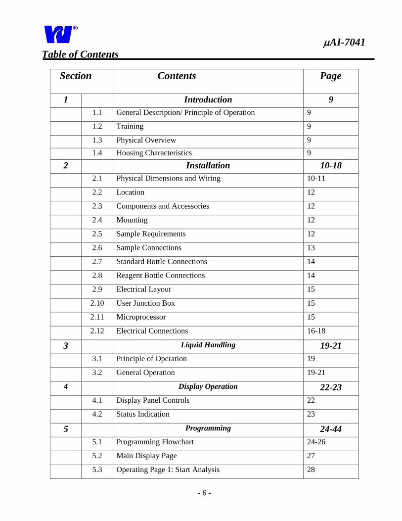
1 Introduction 9
1.1 General Description/ Principle of Operation 9
1.2 Training 9
1.3 Physical Overview 9
1.4 Housing Characteristics 9
2 Installation 10-18
2.1 Physical Dimensions and Wiring 10-11
2.2 Location 12
2.3 Components and Accessories 12
2.4 Mounting 12
2.5 Sample Requirements 12
2.6 Sample Connections 13
2.7 Standard Bottle Connections 14
2.8 Reagent Bottle Connections 14
2.9 Electrical Layout 15
2.10 User Junction Box 15
2.11 Microprocessor 15
2.12 Electrical Connections 16-18
3 Liquid Handling 19-21
3.1 Principle of Operation 19
3.2 General Operation 19-21
4 Display Operation 22-23
4.1 Display Panel Controls 22
4.2 Status Indication 23
5 Programming 24-44
5.1 Programming Flowchart 24-26
5.2 Main Display Page 27
5.3 Operating Page 1: Start Analysis 28
AI-7041
- 7 -
Table of Contents
Section
Contents
Page
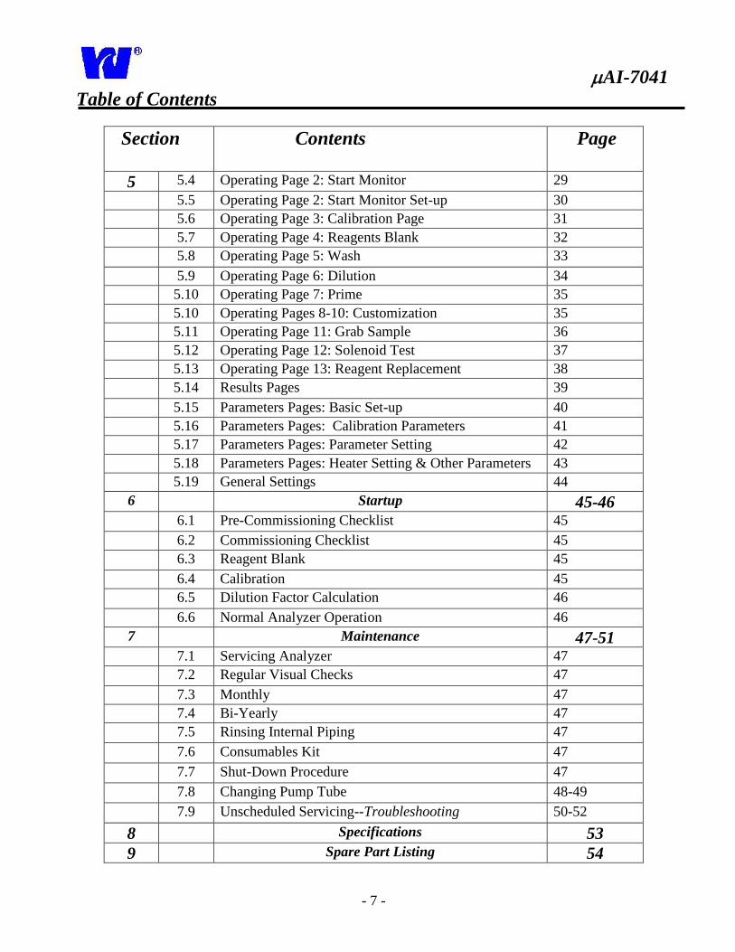
5 5.4 Operating Page 2: Start Monitor 29
5.5 Operating Page 2: Start Monitor Set-up 30
5.6 Operating Page 3: Calibration Page 31
5.7 Operating Page 4: Reagents Blank 32
5.8 Operating Page 5: Wash 33
5.9 Operating Page 6: Dilution 34
5.10 Operating Page 7: Prime 35
5.10 Operating Pages 8-10: Customization 35
5.11 Operating Page 11: Grab Sample 36
5.12 Operating Page 12: Solenoid Test 37
5.13 Operating Page 13: Reagent Replacement 38
5.14 Results Pages 39
5.15 Parameters Pages: Basic Set-up 40
5.16 Parameters Pages: Calibration Parameters 41
5.17 Parameters Pages: Parameter Setting 42
5.18 Parameters Pages: Heater Setting & Other Parameters 43
5.19 General Settings 44
6 Startup 45-46
6.1 Pre-Commissioning Checklist 45
6.2 Commissioning Checklist 45
6.3 Reagent Blank 45
6.4 Calibration 45
6.5 Dilution Factor Calculation 46
6.6 Normal Analyzer Operation 46
7 Maintenance 47-51 7.1 Servicing Analyzer 47
7.2 Regular Visual Checks 47
7.3 Monthly 47
7.4 Bi-Yearly 47
7.5 Rinsing Internal Piping 47
7.6 Consumables Kit 47
7.7 Shut-Down Procedure 47
7.8 Changing Pump Tube 48-49
7.9 Unscheduled Servicing--Troubleshooting 50-52
8 Specifications 53
9 Spare Part Listing 54
AI-7041
- 8 -
1 Introduction-General Overview
1.1 General Description
The AI-7041 Silica Analyzer is a
microprocessor based colorimetric
analyzer. The analyzer is capable of
measuring silica levels in demineralization
and steam generation plants. The
instrument is available in single stream or
multi-stream configurations.
The AI-7041 Silica Analyzer is based on
Loop Flow Analysis (LFA), an exclusive
and patented technology that has allowed
Waltron LLC to make new advances in
analytical automation. This exclusive
technology and compact design allows for
low power usage and reagent
consumption. The analyzer is able to
precisely measure a wide range of values
without compromising accuracy.
1.2 Training
Due to the specialized functions of the
Waltron LLC 7041 Silica Analyzer, it is
recommended that equipment operators be
trained prior to the start-up and operation
of the analyzer.
1.3 Physical Overview
To measure the amount of silica in a
sample, various reagents are added to the
sample to form a chemical complex. This
complex is then detected and measured by
a colorimeter. These steps take place in
the Analytical Compartment.
The Electronic Compartment houses a
microprocessor unit that controls all
instrument functions.
The Electronic and Analytical
Compartments are easily accessed and
front door should be closed during
operation to prevent wear on internal
components.
The front door of the analyzer may be
opened to gain access to the optical
system, solenoid valves and pump motor.
1.4 Housing Characteristics
The AI-7041 housing meets IP55
protection requirements. All parts coming
into contact with the sample and reagents
are chemically inert. The external shape
and dimensions provide easy installation
in industrial plant or interior monitoring
stations. See Technical Specifications
section for more information.
AI-7041
- 9 -
2 Installation
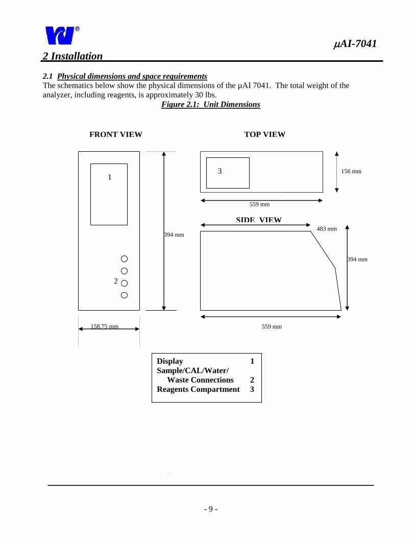
2.1 Physical dimensions and space requirements The schematics below show the physical dimensions of the µAI 7041. The total weight of the
analyzer, including reagents, is approximately 30 lbs.
Figure 2.1: Unit Dimensions
394 mm
158.75 mm
156 mm
Display 1
Sample/CAL/Water/
Waste Connections 2
Reagents Compartment 3
FRONT VIEW
SIDE VIEW
TOP VIEW
1
2
559 mm
483 mm
394 mm
559 mm
3
AI-7041
- 10 -
2 Installation
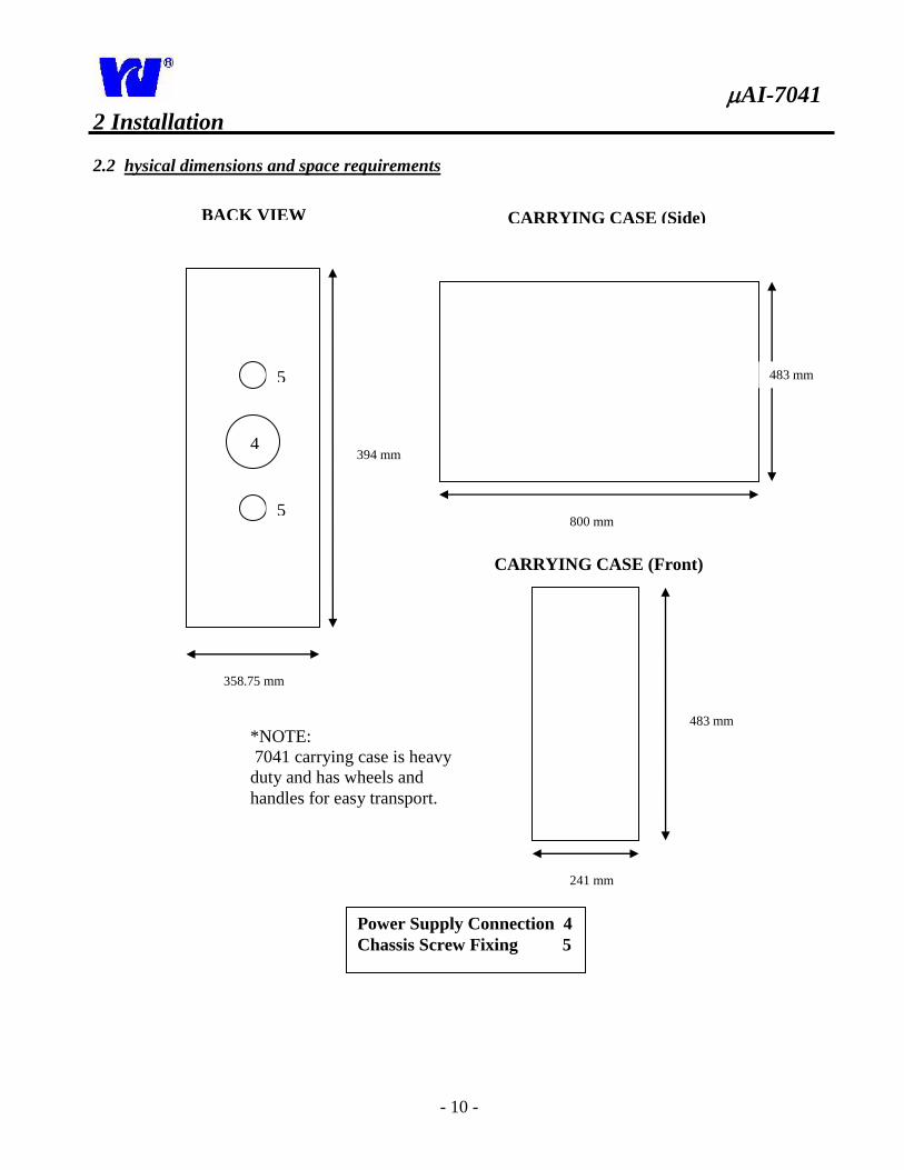
2.2 hysical dimensions and space requirements
394 mm
358.75 mm
4
Power Supply Connection 4
Chassis Screw Fixing 5
CARRYING CASE (Side)
5
5 800 mm
483 mm
CARRYING CASE (Front)
241 mm
483 mm
*NOTE:
7041 carrying case is heavy
duty and has wheels and
handles for easy transport.
BACK VIEW
AI-7041
- 11 -
2 Installation
2.3 Location
Proper analyzer location is an important factor in ensuring accuracy, reliability, and minimizing
maintenance. Take careful note of the following to obtain peak analyzer performance.
Place the analyzer in clean, dry, well-ventilated and vibration-free location. Make sure the
analyzer is easily accessible. Avoid installing in rooms containing corrosive gases or
vapors, e.g. chlorination equipment or chlorine gas cylinders. Use adjacent drains located
at ground level to minimize waste line length and utilize maximum fall.
The monitor and power supplies should rest in close proximity to the sample point in order
to minimize response delays.
Maintain ambient room temperature of 5-40C.
Although the analyzer does not require a continuous supply of deionized water, a
continuous stream is highly recommended for:
1. Quality Assurance and zero calibration testing.
2. Use as a back-up sample source during outages and out of sample conditions.
2.4 Components and Accessories
Analyzer accessories include:
4 Reagents containers.
Calibration container.
DI water container. (NOTE: For analyzers using auto dilution an additional external
container may be necessary.)
Consumables kit. (Includes 12-micro filters used for monthly analysis.)
2.5 Mounting—Figure 2.1
See Figure 2.1 for mounting procedure and physical dimensions.
2.6 Sample Requirements
The sample reservoir should be located as close to the monitor as possible. The sample point must
also provide a thoroughly mixed representative sample. The sample must conform to the
following conditions:
Sample temperature should be 5-55C (41-131 F).
Sample particle concentration must be less than 10 mg/l. Particle size must not
exceed 60 microns. If particle size does exceed 60 microns, a filter must be fitted in
both the sample and emergency inlets.
AI-7041
- 12 -
2 Installation
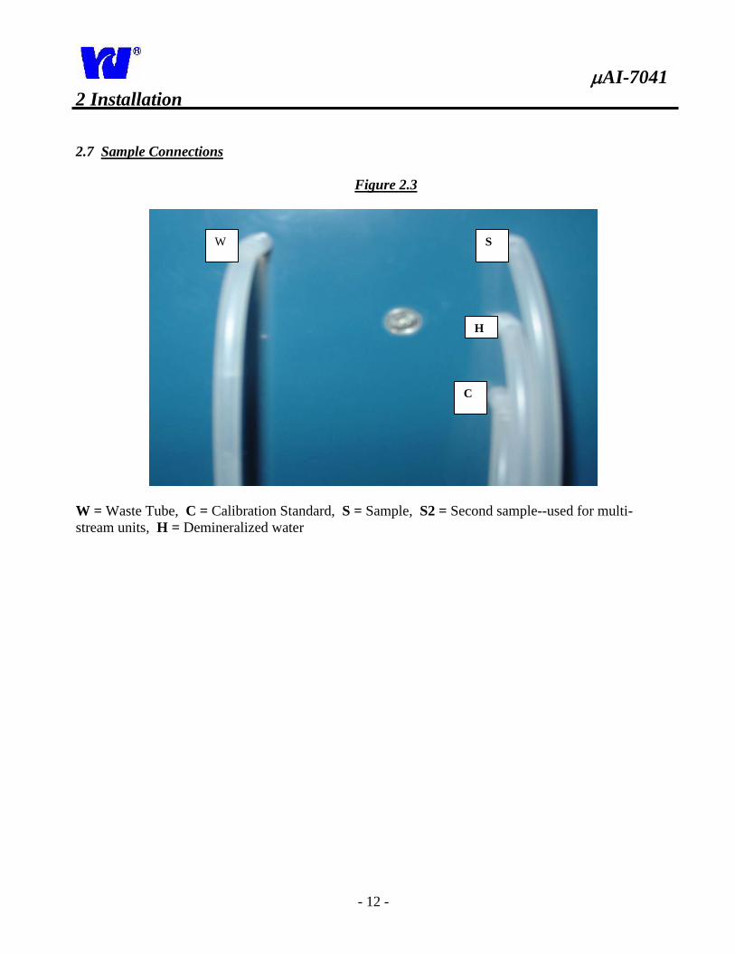
2.7 Sample Connections
Figure 2.3
W = Waste Tube, C = Calibration Standard, S = Sample, S2 = Second sample--used for multi-
stream units, H = Demineralized water
S
H
C
W
AI-7041
- 13 -
V1
2 Installation
2.8 Standard Bottle Connections
Clean standard and deionized water bottles with DI water and dry before use.
Using the labels on the tubing, insert each tube and straw into their respective
containers. Make sure that the straw reaches the bottom of the container.
Insert the straw from tubing C into the silica calibrant standard bottle.
Uses approximately 200 ml for every calibration cycle (5 tests per 1 liter)
Insert the straw from tubing H into DI water
Used for initial start-up, wash, and dilution.
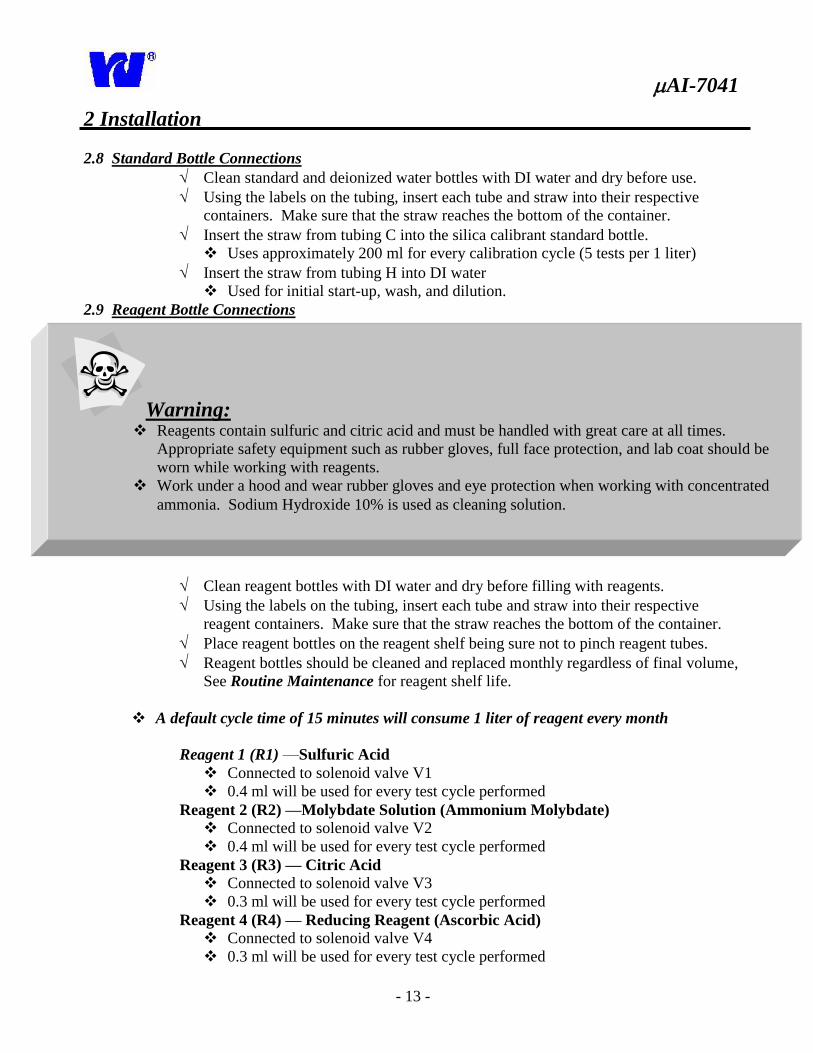
2.9 Reagent Bottle Connections
Clean reagent bottles with DI water and dry before filling with reagents.
Using the labels on the tubing, insert each tube and straw into their respective
reagent containers. Make sure that the straw reaches the bottom of the container.
Place reagent bottles on the reagent shelf being sure not to pinch reagent tubes.
Reagent bottles should be cleaned and replaced monthly regardless of final volume,
See Routine Maintenance for reagent shelf life.
A default cycle time of 15 minutes will consume 1 liter of reagent every month
Reagent 1 (R1) —Sulfuric Acid
Connected to solenoid valve V1
0.4 ml will be used for every test cycle performed
Reagent 2 (R2) —Molybdate Solution (Ammonium Molybdate) Connected to solenoid valve V2
0.4 ml will be used for every test cycle performed
Reagent 3 (R3) — Citric Acid Connected to solenoid valve V3
0.3 ml will be used for every test cycle performed
Reagent 4 (R4) — Reducing Reagent (Ascorbic Acid)
Connected to solenoid valve V4
0.3 ml will be used for every test cycle performed
Warning:
Reagents contain sulfuric and citric acid and must be handled with great care at all times.
Appropriate safety equipment such as rubber gloves, full face protection, and lab coat should be
worn while working with reagents.
Work under a hood and wear rubber gloves and eye protection when working with concentrated
ammonia. Sodium Hydroxide 10% is used as cleaning solution.
AI-7041
- 14 -
2 Installation
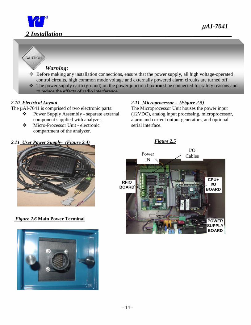
2.10 Electrical Layout The µAI-7041 is comprised of two electronic parts:
Power Supply Assembly - separate external
component supplied with analyzer.
Micro-Processor Unit - electronic
compartment of the analyzer.
2.11 User Power Supply- (Figure 2.4)
2.11 Microprocessor - (Figure 2.5) The Microprocessor Unit houses the power input
(12VDC), analog input processing, microprocessor,
alarm and current output generators, and optional
serial interface.
Figure 2.5
Figure 2.6 Main Power Terminal
Warning: Before making any installation connections, ensure that the power supply, all high voltage-operated
control circuits, high common mode voltage and externally powered alarm circuits are turned off.
The power supply earth (ground) on the power junction box must be connected for safety reasons and
to reduce the effects of radio interference.
I/O
Cables
RFIO
BOARD
CPU+ I/O
BOARD
POWER SUPPLY
BOARD
Power
IN
AI-7041
- 15 -
2 Installation
2.12 Electrical Connections:
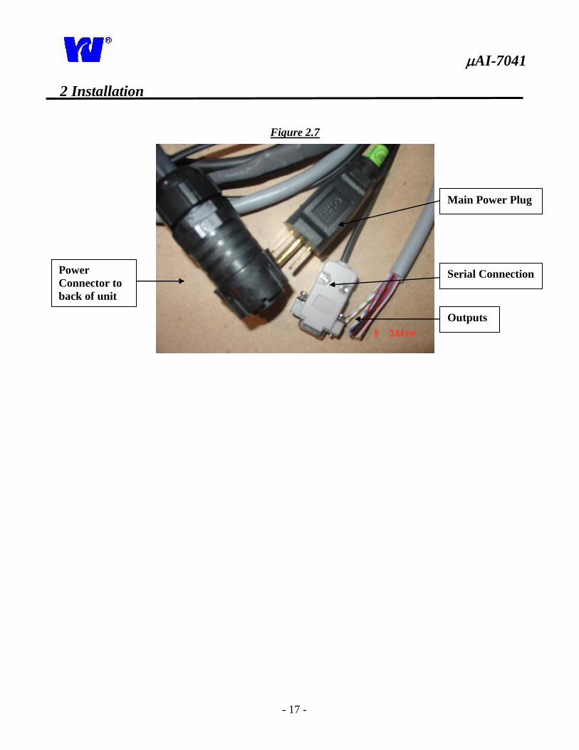
Main Power Input – Figure 2.6
1. Connect power supply cord to main power terminal located on the back of the analyzer.
2. Power on the unit by connecting power supply cord to power source.
Current Outputs
One current output is supplied for single stream operations. Two outputs are supplied for multi-
parameter operations such as silica/phosphate combination units or dual stream analyzers. The
most recent current output value will be recorded and used during the next analysis.
To Install Current Outputs:
1. Feed the cable(s) through the holes in the top of the electronic compartment
2. Attach the leads to the RFIO board terminal block P8 (1-Negative out, 2-Positive out).
These outputs are set at default range of 4-20mA, but are configurable to 0-20mA and
0/5VDC. (See Figure 2.7 Below)
Alarm/Relay Contacts:
Alarm is able to be monitored and controlled from a remote location. An alarm may be used to
indicate:
1. Busy—Analyzer is in operation
2. Dilution Method
3. High Concentration Alarm
4. Calibration Error
5. Error—(Analyzer is out of sample or out of service)
The following diagram shows the installation of alarm relays and contacts. Refer to Figure 2.7 for
corresponding positions on the RFIO board terminal strip.
Note: The green Sample LED light located on the display will illuminate when the analyzer has
been wired correctly and the junction box has been turned on. Remember to turn off the power (verify that the
LED on the display is off) while working with the electrical components.
AI-7041
- 16 -
2 Installation
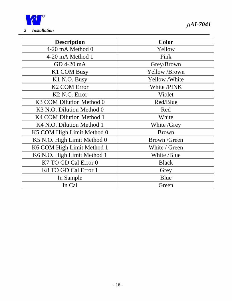
Description Color
4-20 mA Method 0 Yellow
4-20 mA Method 1 Pink
GD 4-20 mA Grey/Brown
K1 COM Busy Yellow /Brown
K1 N.O. Busy Yellow /White
K2 COM Error White /PINK
K2 N.C. Error Violet
K3 COM Dilution Method 0 Red/Blue
K3 N.O. Dilution Method 0 Red
K4 COM Dilution Method 1 White
K4 N.O. Dilution Method 1 White /Grey
K5 COM High Limit Method 0 Brown
K5 N.O. High Limit Method 0 Brown /Green
K6 COM High Limit Method 1 White / Green
K6 N.O. High Limit Method 1 White /Blue
K7 TO GD Cal Error 0 Black
K8 TO GD Cal Error 1 Grey
In Sample Blue
In Cal Green
AI-7041
- 17 -
2 Installation
Figure 2.7
Power
Connector to
back of unit
Main Power Plug
Serial Connection
Outputs
AI-7041
- 18 -
3 Liquid Handling Section-Analytical Compartment
3.1 Principle of Operation
Using the features patented under Loop Flow
Analysis, the analyzer is able to measure and
interpret the amount of silica contained in a sample
stream.
After the acid and molybdate reagents are added to
the sample the mixture is reduced by adding the
third reagent. The analyzer then reads and records
the optical density which is used to determine the
amount of silica.
Chemical reaction sequence: 1. Sulfuric Acid and Ammonium Molybdate are
added to the sample.
2. While controlling temperature, the solution is
put in closed loop where mixing occurs and
yellow beta-molybdosilicic acid is developed.
3. Citric Acid is added to lower pH and prepare
mixture for reduction process.
4. Ascorbic Acid is added to reduce the solution
and form the final (blue) complex. The optical
density is read and converted into a silica
measurement.
5. The optical density of the mixed sample is
measured continuously during the entire
procedure so that a true zero calibration can be
performed for every cycle. The optical density
can be viewed during the entire process on the
display graph. A secondary calibration is
achieved by automatically introducing a
standard solution of known value.
3.2 General Operation Figure 3.1 and 3.2 Sample enters constant head unit situated in the
bottom of the analytical compartment behind the
hydraulic panel. The constant head unit is fitted
with an out of sample switch that, when
activated, relays an alarm and puts the analyzer
in standby mode.
For Multi-Stream Analyzers, each sample inlet
is fed into a separate constant head unit
complete with float, S-tube and alarm.
The sample is taken from the constant head and
S tube and flows into the Loop Flow Reactor.
The sample is fed to solenoid VC4.
Steps in the LFR: 1. Sample is taken from sample stream and introduced
into analyzer. Sample blank measurement and
colorimeter zeroing.
2. Reagent injection in chemical reaction sequence.
3. Sample and reagent mixing.
4. Heating (optional).
5. Optical density measurement using a double beam
colorimeter.
6. Automatic sample dilution in case of full-scale
reading.
7. End point measurement stored in non volatile RAM
for remote and local readings.
8. Concentration value calculation based on the
correlation with internal calibration factor.
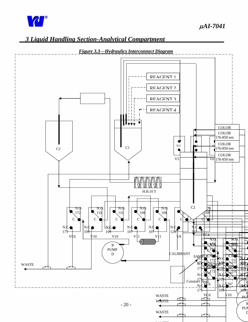
Components in the LFR (Figures 3.1, 3.2):
1. The analytical reactor is made up of three
interconnected pieces (mechanical, hydraulics,
optical). Together these parts make up the LOOP
FLOW REACTOR (LFR).
2. In the case of exceedingly high silica concentrations,
the analyzer is still able to perform an analysis by
automatically diluting the sample.
3. Status (open or closed) of valve Vs/l determines if
LFR is operating in SAMPLE or LOOP mode.
Valve V11(VDil) is activated when a sample
dilution is needed.
4. Reagent solenoid valves control the injection of the
reagents in the LFR. The pressure change in
cylinder C1 mixes reagents and sample.
5. Valve V6, when activated, interrupts the LFR
by producing a vacuum inside C1. This vacuum
produces the negative pressure needed for
reagent introduction.
6. Pump P is a single tube peristaltic pump that can
be activated in direct or reverse mode. 7. Status (open or closed) of valves V8 and VC4
determine if sample, diluent or calibrant is flowing.
8. Cylinder C2 holds sample transferred from C1
during the reverse pump/vacuum production process.
AI-7041
- 19 -
3 Liquid Handling Section-Analytical Compartment
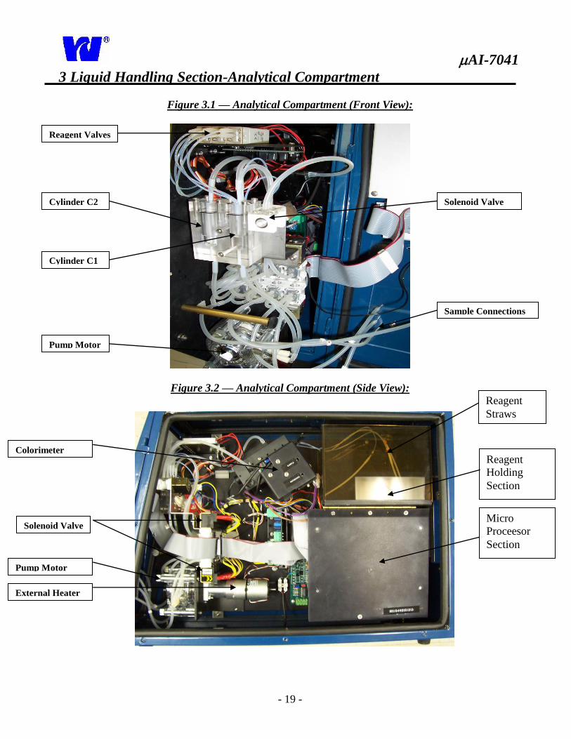
Figure 3.1 — Analytical Compartment (Front View):
Figure 3.2 — Analytical Compartment (Side View):
Reagent Valves
Cylinder C2
Cylinder C1
Pump Motor
Solenoid Valve
Sample Connections
External Heater
Colorimeter
Solenoid Valve
Pump Motor
Reagent
Holding
Section
Micro
Proceesor
Section
Reagent
Straws
AI-7041
- 20 -
3 Liquid Handling Section-Analytical Compartment
Figure 3.3—Hydraulics Interconnect Diagram
Constan t Head
Air
R PUMP
D
WASTE
C2 C1
N.C .
N.O .
N.C .
V6
N.C 171
C
N.O. 172
VC6
N.C 109
C
N .O. 110
V10
N.C 109
C
N.O. 110
V10
N.C 107
C
N.O. 108
V11
N.C 107
C
N.O. 108
V11
N.C 124
C
N.O. 125
V8
N.C 167
C
N.O. 168
VC4
CALIBRANT SAMPLE
WATER
V5
V7
H.B.10 T
REAGENT 1
11
Constant Head
Air
R
PUMP
D
WASTE
C2 C1 N.C
. N.O
.
N.C
.
V6
N.C
171
C
N.O.
172
VC6
N.C
109
C
N.O.
110
V10
N.C
109
C
N.O.
110
V10
N.C
107
C
N.O.
108
V11
N.C
107
C
N.O.
108
V11
N.C
124
C
N.O.
125
V8
N.C
167
C
N.O.
168
VC4
70 R2 color
69 R1 acid
CALIBRANT SAMPLE
COLOR
176-850 nm
WATER
V5
71 R3 reduci
V7
H.B.10 T
EAGENT 1
REAGENT 2
Constant Head
Air
R
PUMP
D
WASTE
C2 C1 N.C
. N.O
.
N.C
.
V6
N.C
171
C
N.O.
172
VC6
N.C
109
C
N.O.
110
V10
N.C
109
C
N.O.
110
V10
N.C
107
C
N.O.
108
V11
N.C
107
C
N.O.
108
V11
N.C
124
C
N.O.
125
V8
N.C
167
C
N.O.
168
VC4
70 R2 color
69 R1 acid
CALIBRANT SAMPLE
COLOR
176-850 nm
WATER
V5
71 R3 reduci
V7
H.B.10 T
EAGENT 1
REAGENT 3
Constant Head
Air
R
PUMP
D
WASTE
C2 C1 N.C
. N.O
.
N.C
.
V6
N.C
171
C
N.O.
172
VC6
N.C
109
C
N.O.
110
V10
N.C
109
C
N.O.
110
V10
N.C
107
C
N.O.
108
V11
N.C
107
C
N.O.
108
V11
N.C
124
C
N.O.
125
V8
N.C
167
C
N.O.
168
VC4
70 R2 color
69 R1 acid
CALIBRANT SAMPLE
COLOR
176-850 nm
WATER
V5
71 R3 reduci
V7
H.B.10 T
REAGENT 4
Constant Head
Air
R
PUMP
D
WASTE
C2 C1 N.C
. N.O
.
N.C
.
V6
N.C
171
C
N.O.
172
VC6
N.C
109
C
N.O.
110
V10
N.C
109
C
N.O.
110
V10
N.C
107
C
N.O.
108
V11
N.C
107
C
N.O.
108
V11
N.C
124
C
N.O.
125
V8
N.C
167
C
N.O.
168
VC4
70 R2 color
69 R1 acid
CALIBRANT SAMPLE
COLOR
176-850 nm
WATER
V5
71 R3 reduci
V7
H.B.10 T
AI-7041
- 21 -
CLR
F
.
Enter
ON
OFF
Power
(0-9)
4 Display Operation
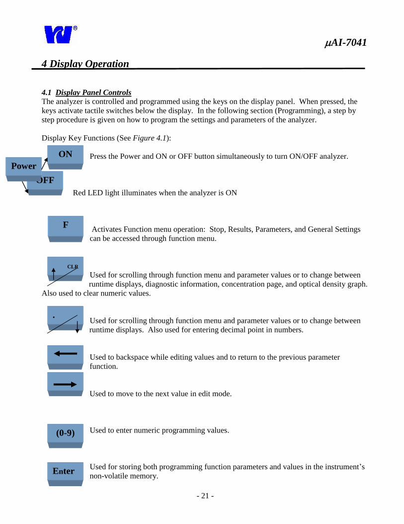
4.1 Display Panel Controls The analyzer is controlled and programmed using the keys on the display panel. When pressed, the
keys activate tactile switches below the display. In the following section (Programming), a step by
step procedure is given on how to program the settings and parameters of the analyzer.
Display Key Functions (See Figure 4.1):
Press the Power and ON or OFF button simultaneously to turn ON/OFF analyzer.
Red LED light illuminates when the analyzer is ON
Activates Function menu operation: Stop, Results, Parameters, and General Settings
can be accessed through function menu.
Used for scrolling through function menu and parameter values or to change between
runtime displays, diagnostic information, concentration page, and optical density graph.
Also used to clear numeric values.
Used for scrolling through function menu and parameter values or to change between
runtime displays. Also used for entering decimal point in numbers.
Used to backspace while editing values and to return to the previous parameter
function.
Used to move to the next value in edit mode.
Used to enter numeric programming values.
Used for storing both programming function parameters and values in the instrument’s
non-volatile memory.
AI-7041
- 22 -
4 Display Operation:
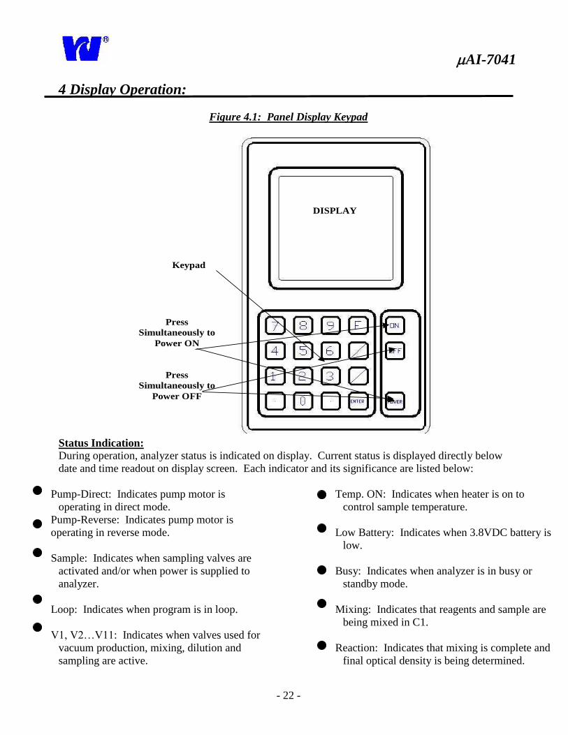
Figure 4.1: Panel Display Keypad
DISPLAY
Press
Simultaneously to
Power ON
Press
Simultaneously to
Power OFF
Keypad
Status Indication: During operation, analyzer status is indicated on display. Current status is displayed directly below
date and time readout on display screen. Each indicator and its significance are listed below:
Pump-Direct: Indicates pump motor is
operating in direct mode.
Pump-Reverse: Indicates pump motor is
operating in reverse mode.
Sample: Indicates when sampling valves are
activated and/or when power is supplied to
analyzer.
Loop: Indicates when program is in loop.
V1, V2…V11: Indicates when valves used for
vacuum production, mixing, dilution and
sampling are active.
Temp. ON: Indicates when heater is on to
control sample temperature.
Low Battery: Indicates when 3.8VDC battery is
low.
Busy: Indicates when analyzer is in busy or
standby mode.
Mixing: Indicates that reagents and sample are
being mixed in C1.
Reaction: Indicates that mixing is complete and
final optical density is being determined.
AI-7041
- 23 -
5 Programming
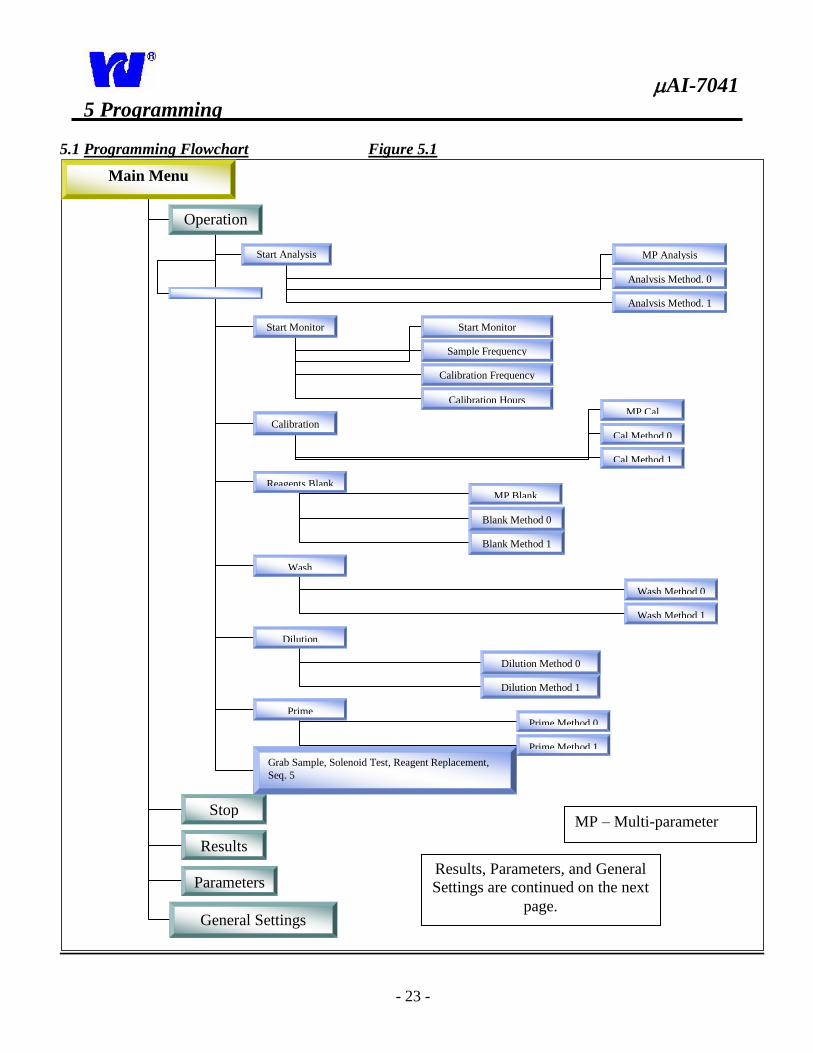
5.1 Programming Flowchart Figure 5.1
Main Menu
Operation
Start Analysis
Stop
MP Analysis
Results
Analysis Method. 0
Analysis Method. 1
Start Monitor Start Monitor
Sample Frequency
Calibration Frequency
Parameters
Calibration Hours
Calibration Cal Method 0
MP Cal
Cal Method 1
Reagents Blank MP Blank
Blank Method 0
Blank Method 1
Wash
Dilution
Wash Method 0
Wash Method 1
Dilution Method 0
Dilution Method 1
Prime
Prime Method 0
Prime Method 1
Grab Sample, Solenoid Test, Reagent Replacement,
Seq. 5
General Settings
Results, Parameters, and General
Settings are continued on the next
page.
MP – Multi-parameter
AI-7041
- 24 -
5 Programming
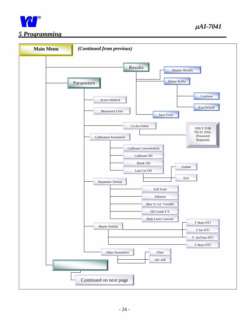
Main Menu
Results
(Continued from previous)
Display Results
Delete Buffer
Continue
Exit/Default
Save From
Parameters
Active Method
Measuring Units
Cycles Editor
Calibration Parameters
Parameter Setting
Heater Setting
Other Parameters
ONLY FOR
TECH. ENG. (Password
Required)
Calibrant Concentration
Calibrant OD
Blank OD
Last Cal OD Update
Exit
Full Scale
Dilution
Max % Cal. Variable
OD Graph F.S.
High Limit Concent. T Mant HT1
T Set HT1
T SetTime HT1
T Mant HT2
Filter
OD AIR
Continued on next page
AI-7041
- 25 -
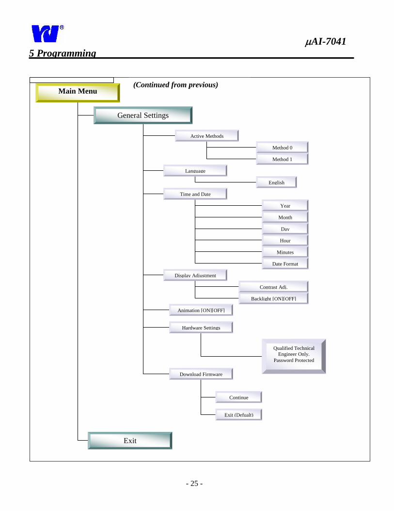
5 Programming
Main Menu
General Settings
(Continued from previous)
Active Methods
Language
Time and Date
Display Adjustment
Method 0
Method 1
English
Year
Month
Day
Hour
Minutes
Date Format
Contrast Adj.
Backlight [ON][OFF]
Animation [ON][OFF]
Hardware Settings
Qualified Technical Engineer Only.
Password Protected
Exit
Download Firmware
Continue
Exit (Defualt)
AI-7041
- 26 -
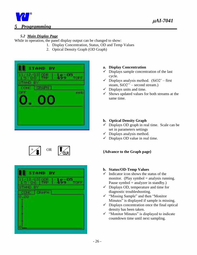
5 Programming
5.2 Main Display Page
While in operation, the panel display output can be changed to show:
1. Display Concentration, Status, OD and Temp Values
2. Optical Density Graph (OD Graph)
OR
a. Display Concentration Displays sample concentration of the last
cycle.
Displays analysis method. (SiO2’ – first
steam, SiO2’’ – second stream.)
Displays units and time.
Shows updated values for both streams at the
same time.
b. Optical Density Graph
Displays OD graph in real time. Scale can be
set in parameters settings
Displays analysis method.
Displays OD value in real time.
{Advance to the Graph page}
b. Status/OD-Temp Values
Indicator icon shows the status of the
monitor. (Play symbol = analysis running.
Pause symbol = analyzer in standby.)
Displays OD, temperature and time for
diagnostic troubleshooting.
“Missing Sample” and then “Monitor
Minutes” is displayed if sample is missing.
Displays concentration once the final optical
density has been taken.
“Monitor Minutes” is displayed to indicate
countdown time until next sampling.
AI-7041
- 27 -
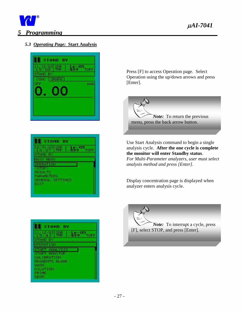
5 Programming
5.3 Operating Page: Start Analysis
Press [F] to access Operation page. Select
Operation using the up/down arrows and press
[Enter].
Use Start Analysis command to begin a single
analysis cycle. After the one cycle is complete
the monitor will enter Standby status.
For Multi-Parameter analyzers, user must select
analysis method and press [Enter].
Display concentration page is displayed when
analyzer enters analysis cycle.
Note: To return the previous
menu, press the back arrow button.
Note: To interrupt a cycle, press
[F], select STOP, and press [Enter].
AI-7041
- 28 -
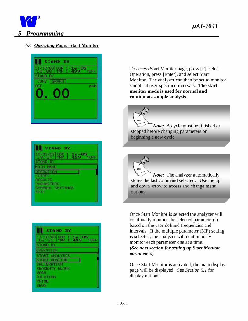
5 Programming
5.4 Operating Page: Start Monitor
To access Start Monitor page, press [F], select
Operation, press [Enter], and select Start
Monitor. The analyzer can then be set to monitor
sample at user-specified intervals. The start
monitor mode is used for normal and
continuous sample analysis.
Once Start Monitor is selected the analyzer will
continually monitor the selected parameter(s)
based on the user-defined frequencies and
intervals. If the multiple parameter (MP) setting
is selected, the analyzer will continuously
monitor each parameter one at a time.
(See next section for setting up Start Monitor
parameters)
Once Start Monitor is activated, the main display
page will be displayed. See Section 5.1 for
display options.
Note: A cycle must be finished or
stopped before changing parameters or
beginning a new cycle.
Note: The analyzer automatically
stores the last command selected. Use the up
and down arrow to access and change menu
options.
AI-7041
- 29 -
Cont.
5 Programming
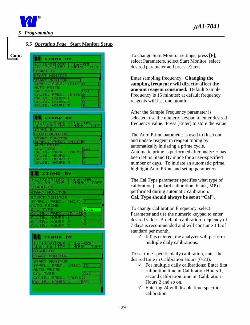
5.5 Operating Page: Start Monitor Setup
To change Start Monitor settings, press [F],
select Parameters, select Start Monitor, select
desired parameter and press [Enter].
Enter sampling frequency. Changing the
sampling frequency will directly affect the
amount reagent consumed. Default Sample
Frequency is 15 minutes; at default frequency
reagents will last one month.
After the Sample Frequency parameter is
selected, use the numeric keypad to enter desired
frequency value. Press [Enter] to store the value.
The Auto Prime parameter is used to flush out
and update reagent in reagent tubing by
automatically initiating a prime cycle.
Automatic prime is performed after analyzer has
been left is Stand By mode for a user-specified
number of days. To initiate an automatic prime,
highlight Auto Prime and set up parameters.
The Cal Type parameter specifies what type of
calibration (standard calibration, blank, MP) is
performed during automatic calibration.
Cal. Type should always be set at “Cal”.
To change Calibration Frequency, select
Parameter and use the numeric keypad to enter
desired value. A default calibration frequency of
7 days is recommended and will consume 1 L of
standard per month.
If 0 is entered, the analyzer will perform
multiple daily calibrations.
To set time-specific daily calibration, enter the
desired time in Calibration Hours (0-23).
For multiple daily calibrations: Enter first
calibration time in Calibration Hours 1,
second calibration time in Calibration
Hours 2 and so on.
Entering 24 will disable time-specific
calibration.
AI-7041
- 30 -
6 Programming
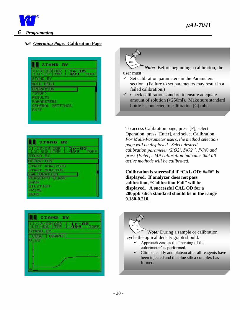
5.6 Operating Page: Calibration Page
To access Calibration page, press [F], select
Operation, press [Enter], and select Calibration.
For Multi-Parameter users, the method selection
page will be displayed. Select desired
calibration parameter (SiO2’, SiO2’’, PO4) and
press [Enter]. MP calibration indicates that all
active methods will be calibrated.
Calibration is successful if “CAL OD: ####” is
displayed. If analyzer does not pass
calibration, “Calibration Fail” will be
displayed. A successful CAL OD for a
200ppb silica standard should be in the range
0.180-0.210.
Note: Before beginning a calibration, the
user must:
Set calibration parameters in the Parameters
section. (Failure to set parameters may result in a
failed calibration.)
Check calibration standard to ensure adequate
amount of solution (>250ml). Make sure standard
bottle is connected to calibration (C) tube.
Note: During a sample or calibration
cycle the optical density graph should: Approach zero as the “zeroing of the
colorimeter’ is performed.
Climb steadily and plateau after all reagents have
been injected and the blue silica complex has
formed.
AI-7041
- 31 -
5 Programming
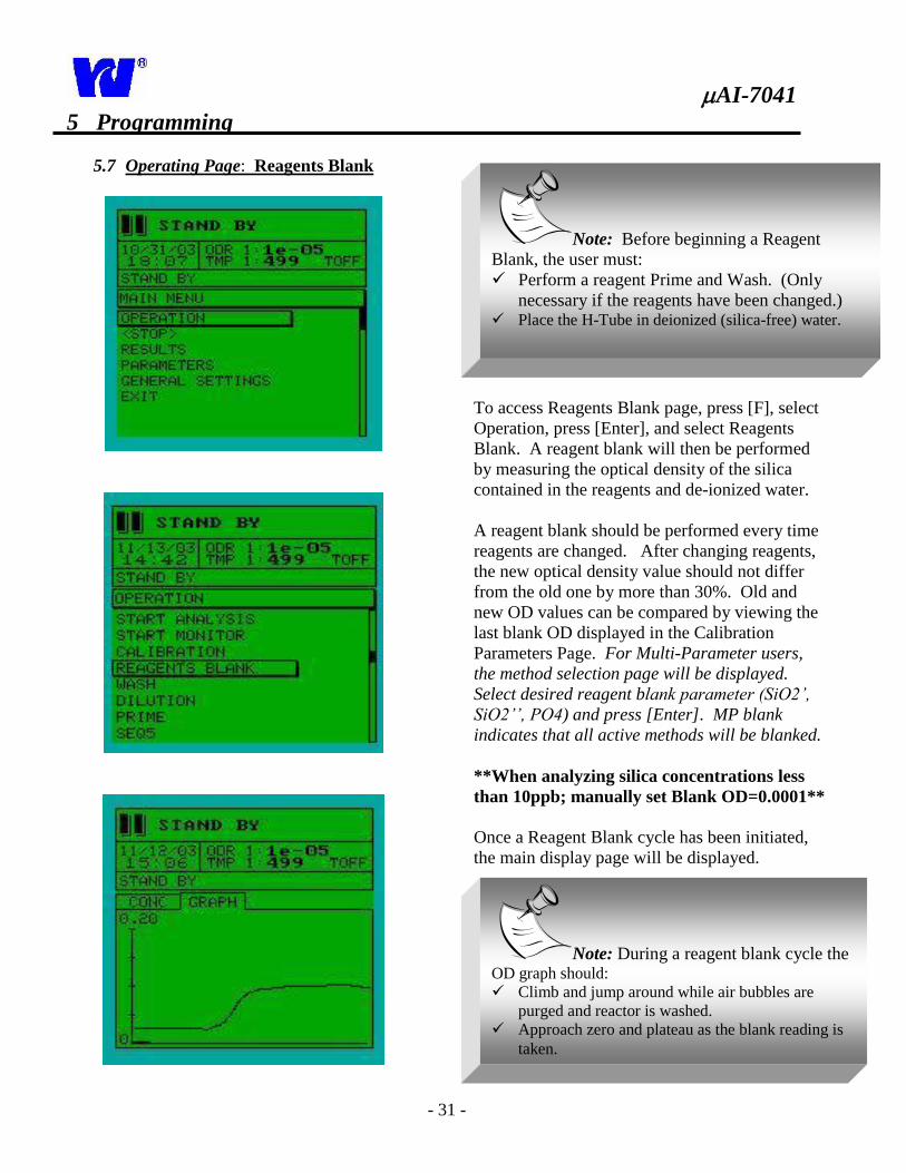
5.7 Operating Page: Reagents Blank
To access Reagents Blank page, press [F], select
Operation, press [Enter], and select Reagents
Blank. A reagent blank will then be performed
by measuring the optical density of the silica
contained in the reagents and de-ionized water.
A reagent blank should be performed every time
reagents are changed. After changing reagents,
the new optical density value should not differ
from the old one by more than 30%. Old and
new OD values can be compared by viewing the
last blank OD displayed in the Calibration
Parameters Page. For Multi-Parameter users,
the method selection page will be displayed.
Select desired reagent blank parameter (SiO2’,
SiO2’’, PO4) and press [Enter]. MP blank
indicates that all active methods will be blanked.
**When analyzing silica concentrations less
than 10ppb; manually set Blank OD=0.0001**
Once a Reagent Blank cycle has been initiated,
the main display page will be displayed.
Note: Before beginning a Reagent
Blank, the user must:
Perform a reagent Prime and Wash. (Only
necessary if the reagents have been changed.) Place the H-Tube in deionized (silica-free) water.
Note: During a reagent blank cycle the OD graph should:
Climb and jump around while air bubbles are
purged and reactor is washed.
Approach zero and plateau as the blank reading is
taken.
AI-7041
- 32 -
5 Programming
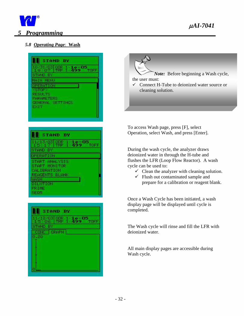
5.8 Operating Page: Wash
To access Wash page, press [F], select
Operation, select Wash, and press [Enter].
During the wash cycle, the analyzer draws
deionized water in through the H-tube and
flushes the LFR (Loop Flow Reactor). A wash
cycle can be used to:
Clean the analyzer with cleaning solution.
Flush out contaminated sample and
prepare for a calibration or reagent blank.
Once a Wash Cycle has been initiated, a wash
display page will be displayed until cycle is
completed.
The Wash cycle will rinse and fill the LFR with
deionized water.
All main display pages are accessible during
Wash cycle.
Note: Before beginning a Wash cycle,
the user must:
Connect H-Tube to deionized water source or
cleaning solution.
AI-7041
- 33 -
5 Programming
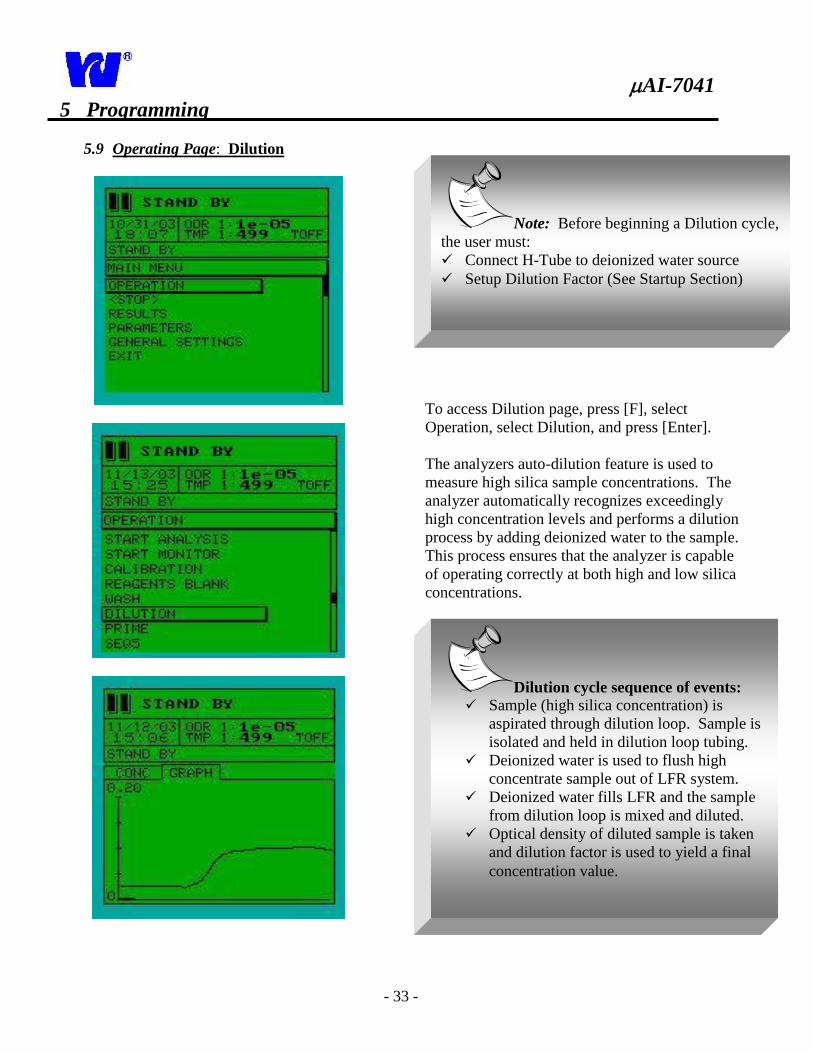
5.9 Operating Page: Dilution
To access Dilution page, press [F], select
Operation, select Dilution, and press [Enter].
The analyzers auto-dilution feature is used to
measure high silica sample concentrations. The
analyzer automatically recognizes exceedingly
high concentration levels and performs a dilution
process by adding deionized water to the sample.
This process ensures that the analyzer is capable
of operating correctly at both high and low silica
concentrations.
Note: Before beginning a Dilution cycle,
the user must:
Connect H-Tube to deionized water source
Setup Dilution Factor (See Startup Section)
Dilution cycle sequence of events: Sample (high silica concentration) is
aspirated through dilution loop. Sample is
isolated and held in dilution loop tubing.
Deionized water is used to flush high
concentrate sample out of LFR system.
Deionized water fills LFR and the sample
from dilution loop is mixed and diluted.
Optical density of diluted sample is taken
and dilution factor is used to yield a final
concentration value.
AI-7041
- 34 -
5 Programming
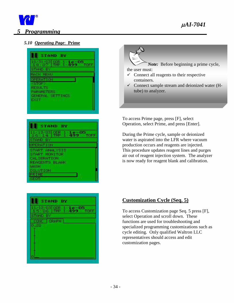
5.10 Operating Page: Prime
To access Prime page, press [F], select
Operation, select Prime, and press [Enter].
During the Prime cycle, sample or deionized
water is aspirated into the LFR where vacuum
production occurs and reagents are injected.
This procedure updates reagent lines and purges
air out of reagent injection system. The analyzer
is now ready for reagent blank and calibration.
Customization Cycle (Seq. 5)
To access Customization page Seq. 5 press [F],
select Operation and scroll down. These
functions are used for troubleshooting and
specialized programming customizations such as
cycle editing. Only qualified Waltron LLC
representatives should access and edit
customization pages.
Note: Before beginning a prime cycle,
the user must:
Connect all reagents to their respective
containers.
Connect sample stream and deionized water (H-
tube) to analyzer.
AI-7041
- 35 -
5 Programming
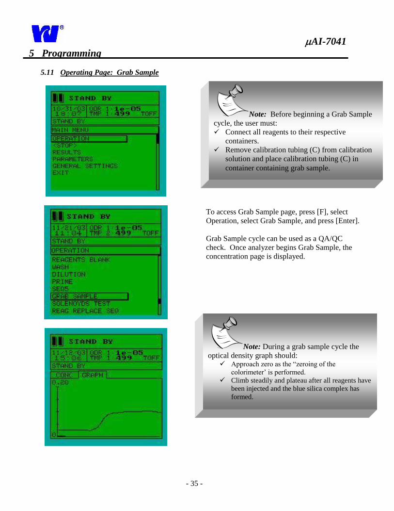
5.11 Operating Page: Grab Sample
To access Grab Sample page, press [F], select
Operation, select Grab Sample, and press [Enter].
Grab Sample cycle can be used as a QA/QC
check. Once analyzer begins Grab Sample, the
concentration page is displayed.
Note: Before beginning a Grab Sample
cycle, the user must:
Connect all reagents to their respective
containers.
Remove calibration tubing (C) from calibration
solution and place calibration tubing (C) in
container containing grab sample.
Note: During a grab sample cycle the
optical density graph should: Approach zero as the “zeroing of the
colorimeter’ is performed.
Climb steadily and plateau after all reagents have
been injected and the blue silica complex has
formed.
AI-7041
- 36 -
5 Programming
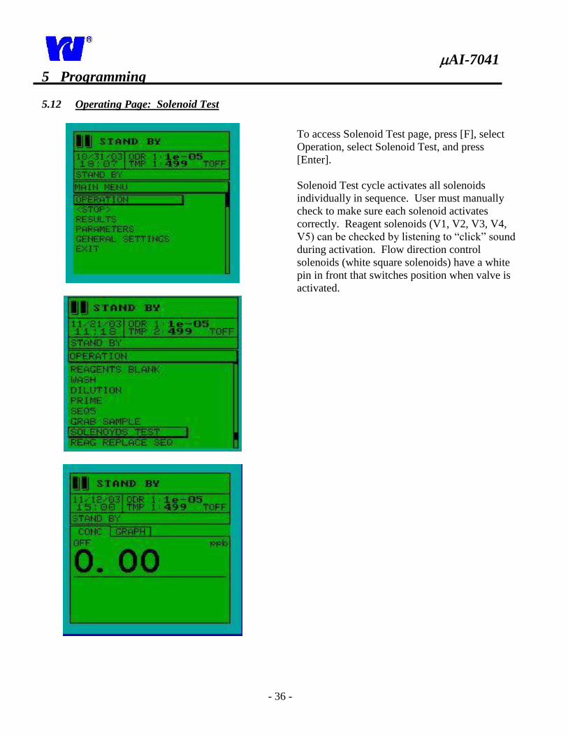
5.12 Operating Page: Solenoid Test
To access Solenoid Test page, press [F], select
Operation, select Solenoid Test, and press
[Enter].
Solenoid Test cycle activates all solenoids
individually in sequence. User must manually
check to make sure each solenoid activates
correctly. Reagent solenoids (V1, V2, V3, V4,
V5) can be checked by listening to “click” sound
during activation. Flow direction control
solenoids (white square solenoids) have a white
pin in front that switches position when valve is
activated.
AI-7041
- 37 -
5 Programming
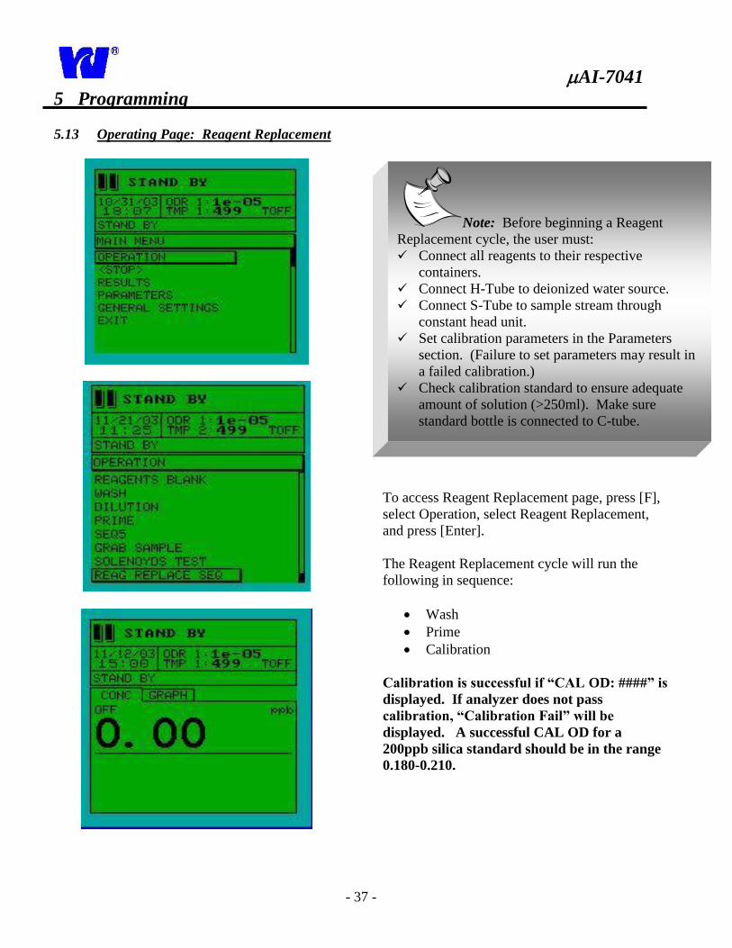
5.13 Operating Page: Reagent Replacement
To access Reagent Replacement page, press [F],
select Operation, select Reagent Replacement,
and press [Enter].
The Reagent Replacement cycle will run the
following in sequence:
Wash
Prime
Calibration
Calibration is successful if “CAL OD: ####” is
displayed. If analyzer does not pass
calibration, “Calibration Fail” will be
displayed. A successful CAL OD for a
200ppb silica standard should be in the range
0.180-0.210.
Note: Before beginning a Reagent
Replacement cycle, the user must:
Connect all reagents to their respective
containers.
Connect H-Tube to deionized water source.
Connect S-Tube to sample stream through
constant head unit.
Set calibration parameters in the Parameters
section. (Failure to set parameters may result in
a failed calibration.)
Check calibration standard to ensure adequate
amount of solution (>250ml). Make sure
standard bottle is connected to C-tube.
AI-7041
- 38 -
5 Programming
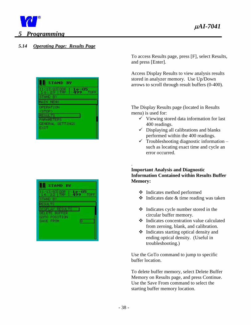
5.14 Operating Page: Results Page
To access Results page, press [F], select Results,
and press [Enter].
Access Display Results to view analysis results
stored in analyzer memory. Use Up/Down
arrows to scroll through result buffers (0-400).
The Display Results page (located in Results
menu) is used for:
Viewing stored data information for last
400 readings.
Displaying all calibrations and blanks
performed within the 400 readings.
Troubleshooting diagnostic information –
such as locating exact time and cycle an
error occurred.
.
Important Analysis and Diagnostic
Information Contained within Results Buffer
Memory:
Indicates method performed
Indicates date & time reading was taken
Indicates cycle number stored in the
circular buffer memory.
Indicates concentration value calculated
from zeroing, blank, and calibration.
Indicates starting optical density and
ending optical density. (Useful in
troubleshooting.)
Use the GoTo command to jump to specific
buffer location.
To delete buffer memory, select Delete Buffer
Memory on Results page, and press Continue.
Use the Save From command to select the
starting buffer memory location.
AI-7041
- 39 -
5 Programming
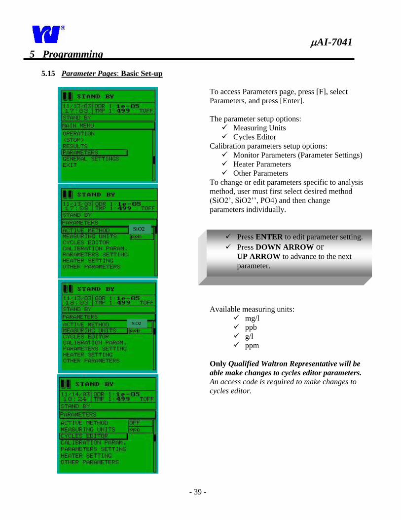
5.15 Parameter Pages: Basic Set-up
SiO2
SiO2
To access Parameters page, press [F], select
Parameters, and press [Enter].
The parameter setup options:
Measuring Units
Cycles Editor
Calibration parameters setup options:
Monitor Parameters (Parameter Settings)
Heater Parameters
Other Parameters
To change or edit parameters specific to analysis
method, user must first select desired method
(SiO2’, SiO2’’, PO4) and then change
parameters individually.
Available measuring units:
mg/l
ppb
g/l
ppm
Only Qualified Waltron Representative will be
able make changes to cycles editor parameters. An access code is required to make changes to
cycles editor.
Press ENTER to edit parameter setting.
Press DOWN ARROW or
UP ARROW to advance to the next
parameter.
AI-7041
- 40 -
5 Programming
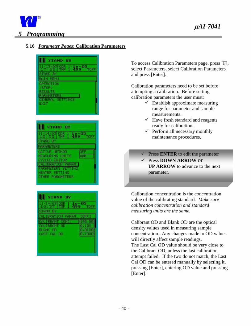
5.16 Parameter Pages: Calibration Parameters
To access Calibration Parameters page, press [F],
select Parameters, select Calibration Parameters
and press [Enter].
Calibration parameters need to be set before
attempting a calibration. Before setting
calibration parameters the user must:
Establish approximate measuring
range for parameter and sample
measurements.
Have fresh standard and reagents
ready for calibration.
Perform all necessary monthly
maintenance procedures.
Calibration concentration is the concentration
value of the calibrating standard. Make sure
calibration concentration and standard
measuring units are the same.
Calibrant OD and Blank OD are the optical
density values used in measuring sample
concentration. Any changes made to OD values
will directly affect sample readings.
The Last Cal OD value should be very close to
the Calibrant OD, unless the last calibration
attempt failed. If the two do not match, the Last
Cal OD can be entered manually by selecting it,
pressing [Enter], entering OD value and pressing
[Enter].
Press ENTER to edit the parameter
Press DOWN ARROW or
UP ARROW to advance to the next
parameter.
AI-7041
- 41 -
5 Programming
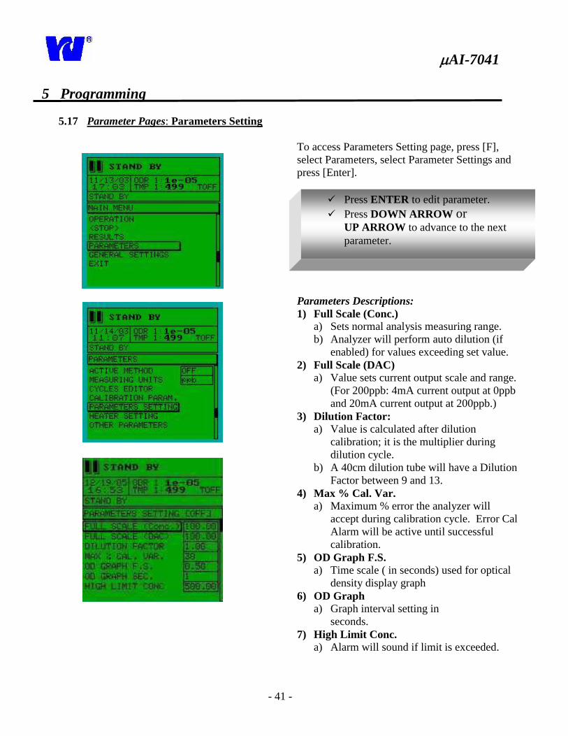
5.17 Parameter Pages: Parameters Setting
To access Parameters Setting page, press [F],
select Parameters, select Parameter Settings and
press [Enter].
Parameters Descriptions:
1) Full Scale (Conc.)
a) Sets normal analysis measuring range.
b) Analyzer will perform auto dilution (if
enabled) for values exceeding set value.
2) Full Scale (DAC)
a) Value sets current output scale and range.
(For 200ppb: 4mA current output at 0ppb
and 20mA current output at 200ppb.)
3) Dilution Factor:
a) Value is calculated after dilution
calibration; it is the multiplier during
dilution cycle.
b) A 40cm dilution tube will have a Dilution
Factor between 9 and 13.
4) Max % Cal. Var.
a) Maximum % error the analyzer will
accept during calibration cycle. Error Cal
Alarm will be active until successful
calibration.
5) OD Graph F.S.
a) Time scale ( in seconds) used for optical
density display graph
6) OD Graph
a) Graph interval setting in
seconds.
7) High Limit Conc.
a) Alarm will sound if limit is exceeded.
Press ENTER to edit parameter.
Press DOWN ARROW or
UP ARROW to advance to the next
parameter.
AI-7041
- 42 -
5 Programming
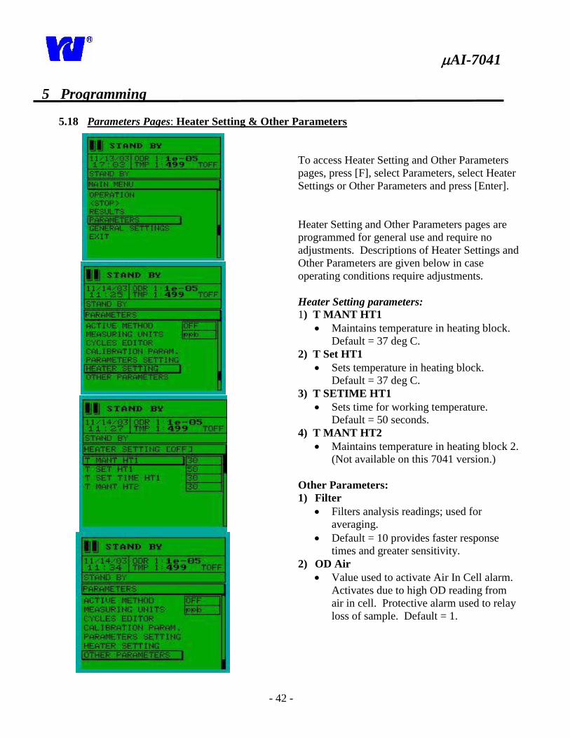
5.18 Parameters Pages: Heater Setting & Other Parameters
To access Heater Setting and Other Parameters
pages, press [F], select Parameters, select Heater
Settings or Other Parameters and press [Enter].
Heater Setting and Other Parameters pages are
programmed for general use and require no
adjustments. Descriptions of Heater Settings and
Other Parameters are given below in case
operating conditions require adjustments.
Heater Setting parameters: 1) T MANT HT1
Maintains temperature in heating block.
Default = 37 deg C.
2) T Set HT1
Sets temperature in heating block.
Default = 37 deg C.
3) T SETIME HT1
Sets time for working temperature.
Default = 50 seconds.
4) T MANT HT2
Maintains temperature in heating block 2.
(Not available on this 7041 version.)
Other Parameters:
1) Filter
Filters analysis readings; used for
averaging.
Default = 10 provides faster response
times and greater sensitivity.
2) OD Air
Value used to activate Air In Cell alarm.
Activates due to high OD reading from
air in cell. Protective alarm used to relay
loss of sample. Default = 1.
AI-7041
- 43 -
5 Programming
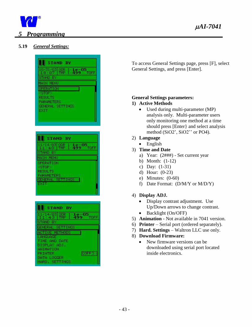
5.19 General Settings:
To access General Settings page, press [F], select
General Settings, and press [Enter].
General Settings parameters:
1) Active Methods
Used during multi-parameter (MP)
analysis only. Multi-parameter users
only monitoring one method at a time
should press [Enter} and select analysis
method (SiO2’, SiO2’’ or PO4).
2) Language
English
3) Time and Date a) Year: (2###) - Set current year
b) Month: (1-12)
c) Day: (1-31)
d) Hour: (0-23)
e) Minutes: (0-60)
f) Date Format: (D/M/Y or M/D/Y)
4) Display ADJ.
Display contrast adjustment. Use
Up/Down arrows to change contrast.
Backlight (On/OFF)
5) Animation - Not available in 7041 version.
6) Printer – Serial port (ordered separately).
7) Hard. Settings – Waltron LLC use only.
8) Download Firmware:
New firmware versions can be
downloaded using serial port located
inside electronics.
AI-7041
- 44 -
6 Start-up
6.1 Pre-Startup Checklist:
Connect calibration tube to calibration bottle.
Connect sample tube to constant head unit.
Turn on sample flow between 100-200
ml/min.
Connect waste tube to contaminated waste
drain.
Connect deionized water tube to full bottle of
deionized water.
Fill reagent containers and insert reagent
tubes into their respective reagent containers.
Supply power to µAI 7041 Silica Analyzer.
6.2 Startup Checklist
Perform Reagent Prime (3-5 min). (Section
5.10)
Perform Wash Cycle (3-5 min). (Section 5.8)
Setup Parameter Settings. (Section 5.15)
i) Select the Active Method for
operation.
ii) Set Full Scale range to accommodate
working sample concentration and
desired 4-20mA current output range.
iii) Set the High limit alarm setting.
6.3 Reagent Blank:
After completing a Reagent Prime and Wash
Cycle, perform a Reagent Blank. (Section
5.7).
When analyzing silica concentrations less
than 10ppb; manually set Blank OD=0.0001
During this cycle, calibration is performed to
determine the amount of background silica in the
reagents and deionized water. The OD should be
close to zero.
6.4 Calibration:
Setup Calibration Parameters: (Section 5.14)
i) Select active method
ii) Enter the calibration standard
concentration. Keep in mind that the
standard supplied by Waltron LLC
may not fit the needs of the user. A
solution standard can be purchased
from Waltron so that a custom
standard can be prepared.
iii) Set Calibration OD. Calibration OD
number should change linearly with
the change in calibrant concentration.
Perform calibration (Section 5.6)
Note: Multi-Parameter users must set
each parameter or stream individually.
Note: Multi-Parameter users must
calibrate each stream. MP command calibrates
each stream automatically.
Multi-stream users working in the
same sample range can set the parameters of
each stream by manually copying the
Calibration OD and Blank OD values.
AI-7041
- 45 -
6 Startup
6.5 Dilution Factor Calculation:
The analyzers auto-dilution feature automatically
recognizes exceedingly high concentration levels
and performs a dilution process by adding
deionized water to the sample.
Dilution Factor calculation should only be
performed when value of dilution factor is in
serious doubt, or if overall system volume is
changed.
In Parameter Settings, enter 1 as the dilution
factor value. (Section 5.15)
Prepare calibration standard that has a value
(D) in desired dilution range. Disconnect S-
tube (sample) and place it in standard
solution.
Make sure deionized water bottle is full and
connected to H-tube.
Start a Dilution cycle. (Section 5.9)
Record the measured concentration reading
(M).
Use formula to calculate Dilution Factor:
Dilution Factor equals the dilution
standard divided by the measured value.
D.F. = (D)/(M) (Typical range 9-13)
Store new Dilution Factor in Parameter
Settings page (Section 5.15)
New Dilution Factor value will be used to
calculate the actual concentration during a
dilution cycle. Dilution can be initiated
manually or automatically once monitor reads
value set above Full Scale value.
6.6 Normal Analyzer Operation
Analyzer is ready to start monitoring once all
calibration cycles have been completed. To start
normal analyzer operation:
Select Active Methods in General Settings
page. (Section 5.17)
Setup Sampling Frequency and Calibration
Frequency.
Start Monitor. The analyzer will now begin
monitoring continuously. Automatic
calibrations will be performed as
programmed. If an error occurs, analyzer
will alarm and go into Standby.
AI-7041
- 46 -
7 Maintenance
7.1 Servicing Analyzer
Servicing and maintenance of analyzer depend
on many factors including installation
environment and sample conditions. Visual
checks, monthly and bi-yearly maintenance
procedures, internal rinsing, and proper
shutdown procedures all promote longer product
life.
7.2 Regular Visual Checks:
The µAI 7041 Silica Analyzer should be visually
inspected on a regular basis to ensure analyzer
accuracy, precision, and efficiency.
Check for leaks particularly around
sample and drain tube connections.
Confirm sample flow by checking sample
delivery to the constant head unit and
effluent entering drain tubing.
Check liquid levels in reagent and
standard solution containers.
Inspect all tubing and liquid handling
components for leaks or deterioration.
Check instrument display for
malfunctioning indications.
7.3 Monthly
Perform visual checks described above.
Discard old reagent and standard
solutions, clean containers thoroughly,
and refill each container with fresh
solution.
Check condition of sample filter (if
fitted), and replace if necessary. Make
sure new filter is fitted correctly by
following directional arrow located on
the filter body.
Perform wash, prime, blank, and
calibration cycles. (Section 6)
Put analyzer back into Monitoring mode.
7.4 Bi-Yearly:
Single pump tube must be changed every six
months. Monthly tubing replacement is not
necessary. Additional bi-yearly maintenance:
Service pump. (Section 7.8)
Perform all monthly calibrations detailed
in Section 7.3.
Clean internal pipe-work with rinse
solution.
7.5 Rinsing Internal Piping:
Internal piping should be cleaned every six
months depending on calibration and sampling
intervals. Waltron can supply and ship cleaning
solution with reagents. The cleaning solution
contains sodium hydroxide, which is extremely
caustic and must be handled with care. Always
wear gloves and eye protection! Place all reagent tubes, sample tube and
deionized water tube into the cleaning
solution.
Put analyzer into a Wash cycle followed
by three Reagent Prime cycles.
7.6 Consumable Spares Kit: Waltron Part Number: W9040-100
The µAI7041 Silica Analyzer comes supplied
with a consumable spare parts kit. This kit
includes all annual replacement components.
Replacement details are given in spare parts kit.
7.7 Shut-Down Procedure
The analyzer can be left on without sample flow.
Analyzer will automatically stop sampling once
it senses missing sample. Reagent lines need to
be cleaned and flushed if the analyzer will be out
of service for more than a month. See Section
7.5 for rinsing internal pipe-work.
AI-7041
- 47 -
7 Maintenance
7.8 Changing Pump Tube:
1. Turn analyzer on and perform a wash cycle to flush out system.
2. Turn analyzer off.
3. Open analytical compartment. Unscrew the four knurled head screws holding the pump head in
place. Take out pump, open it up and remove silicon pump tubing.
4. Install new tubing using the same high density inner diameter nipple. Connect the tube from the
lower side of the pump to the S/L valve, and the tube from the upper side to the bottom nipple of the
cylinder 1.
Attention: If the tube is not properly installed, severe system malfunction will occur!
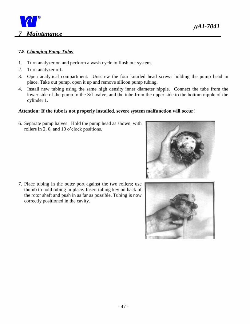
6. Separate pump halves. Hold the pump head as shown, with
rollers in 2, 6, and 10 o’clock positions.
7. Place tubing in the outer port against the two rollers; use
thumb to hold tubing in place. Insert tubing key on back of
the rotor shaft and push in as far as possible. Tubing is now
correctly positioned in the cavity.
AI-7041
- 48 -
7 Maintenance
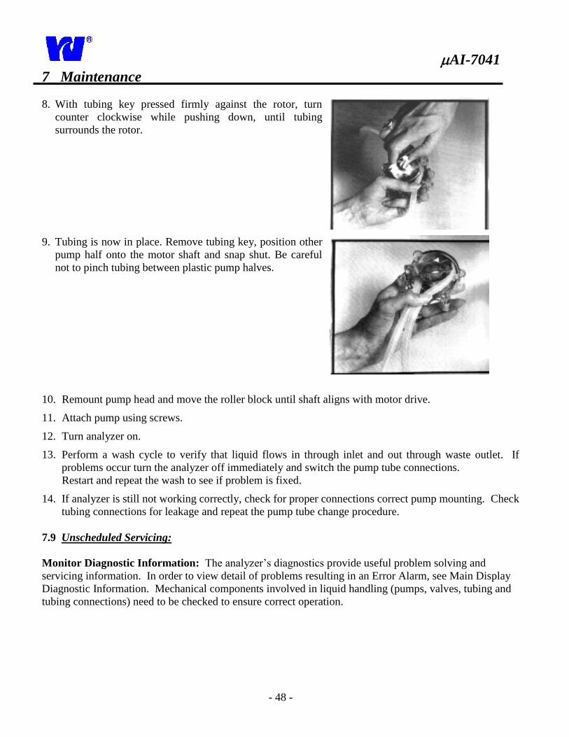
8. With tubing key pressed firmly against the rotor, turn
counter clockwise while pushing down, until tubing
surrounds the rotor.
9. Tubing is now in place. Remove tubing key, position other
pump half onto the motor shaft and snap shut. Be careful
not to pinch tubing between plastic pump halves.
10. Remount pump head and move the roller block until shaft aligns with motor drive.
11. Attach pump using screws.
12. Turn analyzer on.
13. Perform a wash cycle to verify that liquid flows in through inlet and out through waste outlet. If
problems occur turn the analyzer off immediately and switch the pump tube connections.
Restart and repeat the wash to see if problem is fixed.
14. If analyzer is still not working correctly, check for proper connections correct pump mounting. Check
tubing connections for leakage and repeat the pump tube change procedure.
7.9 Unscheduled Servicing:
Monitor Diagnostic Information: The analyzer’s diagnostics provide useful problem solving and
servicing information. In order to view detail of problems resulting in an Error Alarm, see Main Display
Diagnostic Information. Mechanical components involved in liquid handling (pumps, valves, tubing and
tubing connections) need to be checked to ensure correct operation.
AI-7041
- 49 -
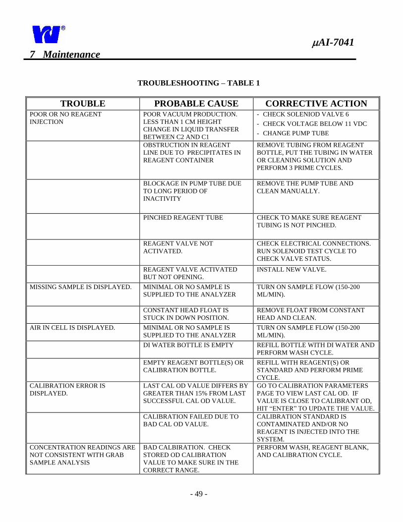
7 Maintenance
TROUBLESHOOTING – TABLE 1
TROUBLE PROBABLE CAUSE CORRECTIVE ACTION POOR OR NO REAGENT
INJECTION
POOR VACUUM PRODUCTION.
LESS THAN 1 CM HEIGHT
CHANGE IN LIQUID TRANSFER
BETWEEN C2 AND C1
- CHECK SOLENIOD VALVE 6
- CHECK VOLTAGE BELOW 11 VDC
- CHANGE PUMP TUBE
OBSTRUCTION IN REAGENT
LINE DUE TO PRECIPITATES IN
REAGENT CONTAINER
REMOVE TUBING FROM REAGENT
BOTTLE, PUT THE TUBING IN WATER
OR CLEANING SOLUTION AND
PERFORM 3 PRIME CYCLES.
BLOCKAGE IN PUMP TUBE DUE
TO LONG PERIOD OF
INACTIVITY
REMOVE THE PUMP TUBE AND
CLEAN MANUALLY.
PINCHED REAGENT TUBE CHECK TO MAKE SURE REAGENT
TUBING IS NOT PINCHED.
REAGENT VALVE NOT
ACTIVATED.
CHECK ELECTRICAL CONNECTIONS.
RUN SOLENOID TEST CYCLE TO
CHECK VALVE STATUS.
REAGENT VALVE ACTIVATED
BUT NOT OPENING.
INSTALL NEW VALVE.
MISSING SAMPLE IS DISPLAYED. MINIMAL OR NO SAMPLE IS
SUPPLIED TO THE ANALYZER
TURN ON SAMPLE FLOW (150-200
ML/MIN).
CONSTANT HEAD FLOAT IS
STUCK IN DOWN POSITION.
REMOVE FLOAT FROM CONSTANT
HEAD AND CLEAN.
AIR IN CELL IS DISPLAYED. MINIMAL OR NO SAMPLE IS
SUPPLIED TO THE ANALYZER
TURN ON SAMPLE FLOW (150-200
ML/MIN).
DI WATER BOTTLE IS EMPTY REFILL BOTTLE WITH DI WATER AND
PERFORM WASH CYCLE.
EMPTY REAGENT BOTTLE(S) OR
CALIBRATION BOTTLE.
REFILL WITH REAGENT(S) OR
STANDARD AND PERFORM PRIME
CYCLE.
CALIBRATION ERROR IS
DISPLAYED.
LAST CAL OD VALUE DIFFERS BY
GREATER THAN 15% FROM LAST
SUCCESSFUL CAL OD VALUE.
GO TO CALIBRATION PARAMETERS
PAGE TO VIEW LAST CAL OD. IF
VALUE IS CLOSE TO CALIBRANT OD,
HIT “ENTER” TO UPDATE THE VALUE.
CALIBRATION FAILED DUE TO
BAD CAL OD VALUE.
CALIBRATION STANDARD IS
CONTAMINATED AND/OR NO
REAGENT IS INJECTED INTO THE
SYSTEM.
CONCENTRATION READINGS ARE
NOT CONSISTENT WITH GRAB
SAMPLE ANALYSIS
BAD CALBIRATION. CHECK
STORED OD CALIBRATION
VALUE TO MAKE SURE IN THE
CORRECT RANGE.
PERFORM WASH, REAGENT BLANK,
AND CALIBRATION CYCLE.
AI-7041
- 50 -
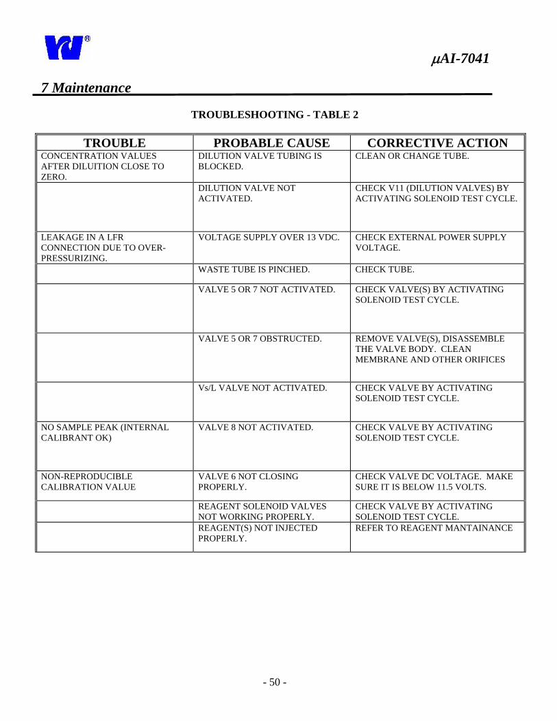
7 Maintenance
TROUBLESHOOTING - TABLE 2
TROUBLE PROBABLE CAUSE CORRECTIVE ACTION CONCENTRATION VALUES
AFTER DILUITION CLOSE TO
ZERO.
DILUTION VALVE TUBING IS
BLOCKED.
CLEAN OR CHANGE TUBE.
DILUTION VALVE NOT
ACTIVATED.
CHECK V11 (DILUTION VALVES) BY
ACTIVATING SOLENOID TEST CYCLE.
LEAKAGE IN A LFR
CONNECTION DUE TO OVER-
PRESSURIZING.
VOLTAGE SUPPLY OVER 13 VDC. CHECK EXTERNAL POWER SUPPLY
VOLTAGE.
WASTE TUBE IS PINCHED. CHECK TUBE.
VALVE 5 OR 7 NOT ACTIVATED. CHECK VALVE(S) BY ACTIVATING
SOLENOID TEST CYCLE.
VALVE 5 OR 7 OBSTRUCTED. REMOVE VALVE(S), DISASSEMBLE
THE VALVE BODY. CLEAN
MEMBRANE AND OTHER ORIFICES
Vs/L VALVE NOT ACTIVATED. CHECK VALVE BY ACTIVATING
SOLENOID TEST CYCLE.
NO SAMPLE PEAK (INTERNAL
CALIBRANT OK)
VALVE 8 NOT ACTIVATED. CHECK VALVE BY ACTIVATING
SOLENOID TEST CYCLE.
NON-REPRODUCIBLE
CALIBRATION VALUE
VALVE 6 NOT CLOSING
PROPERLY.
CHECK VALVE DC VOLTAGE. MAKE
SURE IT IS BELOW 11.5 VOLTS.
REAGENT SOLENOID VALVES
NOT WORKING PROPERLY.
CHECK VALVE BY ACTIVATING
SOLENOID TEST CYCLE.
REAGENT(S) NOT INJECTED
PROPERLY.
REFER TO REAGENT MANTAINANCE
AI-7041
- 51 -
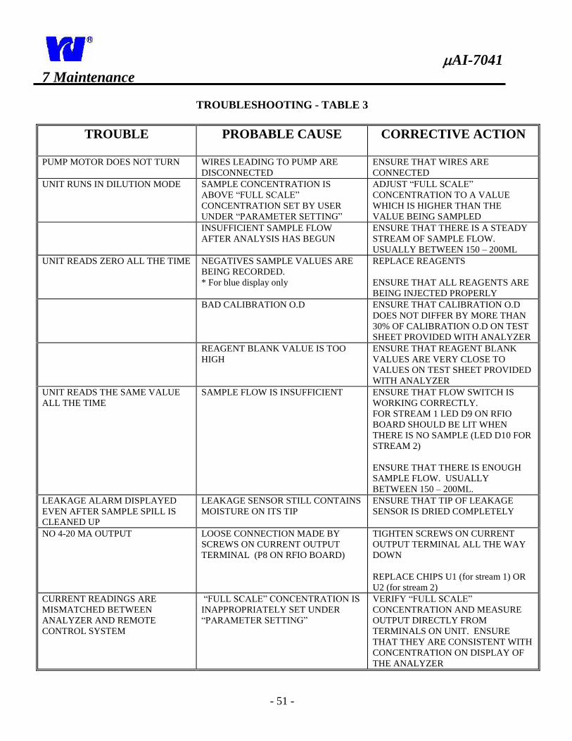
7 Maintenance
TROUBLESHOOTING - TABLE 3
TROUBLE PROBABLE CAUSE CORRECTIVE ACTION
PUMP MOTOR DOES NOT TURN WIRES LEADING TO PUMP ARE
DISCONNECTED
ENSURE THAT WIRES ARE
CONNECTED
UNIT RUNS IN DILUTION MODE SAMPLE CONCENTRATION IS
ABOVE “FULL SCALE”
CONCENTRATION SET BY USER
UNDER “PARAMETER SETTING”
ADJUST “FULL SCALE”
CONCENTRATION TO A VALUE
WHICH IS HIGHER THAN THE
VALUE BEING SAMPLED
INSUFFICIENT SAMPLE FLOW
AFTER ANALYSIS HAS BEGUN
ENSURE THAT THERE IS A STEADY
STREAM OF SAMPLE FLOW.
USUALLY BETWEEN 150 – 200ML
UNIT READS ZERO ALL THE TIME NEGATIVES SAMPLE VALUES ARE
BEING RECORDED.
* For blue display only
REPLACE REAGENTS
ENSURE THAT ALL REAGENTS ARE
BEING INJECTED PROPERLY
BAD CALIBRATION O.D ENSURE THAT CALIBRATION O.D
DOES NOT DIFFER BY MORE THAN
30% OF CALIBRATION O.D ON TEST
SHEET PROVIDED WITH ANALYZER
REAGENT BLANK VALUE IS TOO
HIGH
ENSURE THAT REAGENT BLANK
VALUES ARE VERY CLOSE TO
VALUES ON TEST SHEET PROVIDED
WITH ANALYZER
UNIT READS THE SAME VALUE
ALL THE TIME
SAMPLE FLOW IS INSUFFICIENT ENSURE THAT FLOW SWITCH IS
WORKING CORRECTLY.
FOR STREAM 1 LED D9 ON RFIO
BOARD SHOULD BE LIT WHEN
THERE IS NO SAMPLE (LED D10 FOR
STREAM 2)
ENSURE THAT THERE IS ENOUGH
SAMPLE FLOW. USUALLY
BETWEEN 150 – 200ML.
LEAKAGE ALARM DISPLAYED
EVEN AFTER SAMPLE SPILL IS
CLEANED UP
LEAKAGE SENSOR STILL CONTAINS
MOISTURE ON ITS TIP
ENSURE THAT TIP OF LEAKAGE
SENSOR IS DRIED COMPLETELY
NO 4-20 MA OUTPUT LOOSE CONNECTION MADE BY
SCREWS ON CURRENT OUTPUT
TERMINAL (P8 ON RFIO BOARD)
TIGHTEN SCREWS ON CURRENT
OUTPUT TERMINAL ALL THE WAY
DOWN
REPLACE CHIPS U1 (for stream 1) OR
U2 (for stream 2)
CURRENT READINGS ARE
MISMATCHED BETWEEN
ANALYZER AND REMOTE
CONTROL SYSTEM
“FULL SCALE” CONCENTRATION IS
INAPPROPRIATELY SET UNDER
“PARAMETER SETTING”
VERIFY “FULL SCALE”
CONCENTRATION AND MEASURE
OUTPUT DIRECTLY FROM
TERMINALS ON UNIT. ENSURE
THAT THEY ARE CONSISTENT WITH
CONCENTRATION ON DISPLAY OF
THE ANALYZER
AI-7041
- 52 -
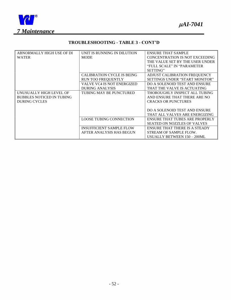
7 Maintenance
TROUBLESHOOTING - TABLE 3 - CONT’D
ABNORMALLY HIGH USE OF DI
WATER
UNIT IS RUNNING IN DILUTION
MODE
ENSURE THAT SAMPLE
CONCENTRATION IS NOT EXCEEDING
THE VALUE SET BY THE USER UNDER
“FULL SCALE” IN “PARAMETER
SETTING”
CALIBRATION CYCLE IS BEING
RUN TOO FREQUENTLY
ADJUST CALIBRATION FREQUENCY
SETTINGS UNDER “START MONITOR”
VALVE VC4 IS NOT ENERGIZED
DURING ANALYSIS
DO A SOLENOID TEST AND ENSURE
THAT THE VALVE IS ACTUATING
UNUSUALLY HIGH LEVEL OF
BUBBLES NOTICED IN TUBING
DURING CYCLES
TUBING MAY BE PUNCTURED THOROUGHLY INSPECT ALL TUBING
AND ENSURE THAT THERE ARE NO
CRACKS OR PUNCTURES
DO A SOLENOID TEST AND ENSURE
THAT ALL VALVES ARE ENERGIZING
LOOSE TUBING CONNECTION ENSURE THAT TUBES ARE PROPERLY
SEATED ON NOZZLES OF VALVES
INSUFFICIENT SAMPLE FLOW
AFTER ANALYSIS HAS BEGUN
ENSURE THAT THERE IS A STEADY
STREAM OF SAMPLE FLOW.
USUALLY BETWEEN 150 – 200ML
AI-7041
- 53 -
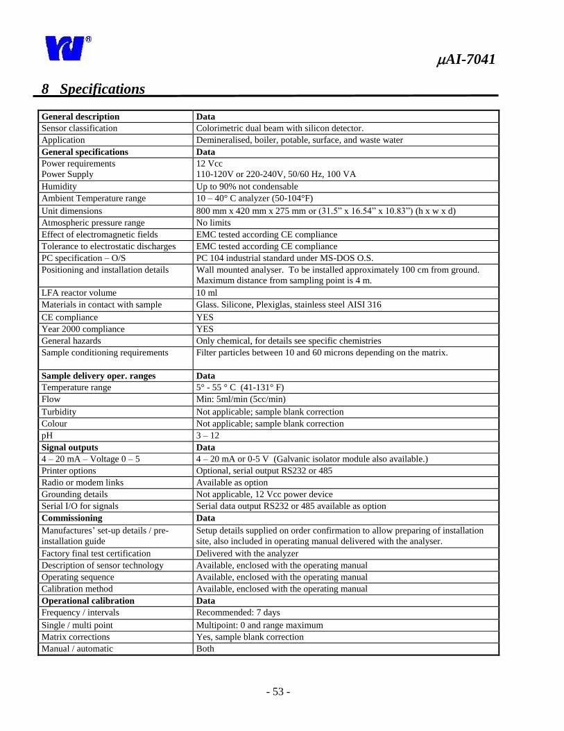
8 Specifications
General description Data
Sensor classification Colorimetric dual beam with silicon detector.
Application Demineralised, boiler, potable, surface, and waste water
General specifications Data
Power requirements
Power Supply
12 Vcc
110-120V or 220-240V, 50/60 Hz, 100 VA
Humidity Up to 90% not condensable
Ambient Temperature range 10 – 40° C analyzer (50-104°F)
Unit dimensions 800 mm x 420 mm x 275 mm or (31.5” x 16.54” x 10.83”) (h x w x d)
Atmospheric pressure range No limits
Effect of electromagnetic fields EMC tested according CE compliance
Tolerance to electrostatic discharges EMC tested according CE compliance
PC specification – O/S PC 104 industrial standard under MS-DOS O.S.
Positioning and installation details Wall mounted analyser. To be installed approximately 100 cm from ground.
Maximum distance from sampling point is 4 m.
LFA reactor volume 10 ml
Materials in contact with sample Glass. Silicone, Plexiglas, stainless steel AISI 316
CE compliance YES
Year 2000 compliance YES
General hazards Only chemical, for details see specific chemistries
Sample conditioning requirements Filter particles between 10 and 60 microns depending on the matrix.
Sample delivery oper. ranges Data
Temperature range 5° - 55 ° C (41-131° F)
Flow Min: 5ml/min (5cc/min)
Turbidity Not applicable; sample blank correction
Colour Not applicable; sample blank correction
pH 3 – 12
Signal outputs Data
4 – 20 mA – Voltage 0 – 5 4 – 20 mA or 0-5 V (Galvanic isolator module also available.)
Printer options Optional, serial output RS232 or 485
Radio or modem links Available as option
Grounding details Not applicable, 12 Vcc power device
Serial I/O for signals Serial data output RS232 or 485 available as option
Commissioning Data
Manufactures’ set-up details / pre-
installation guide
Setup details supplied on order confirmation to allow preparing of installation
site, also included in operating manual delivered with the analyser.
Factory final test certification Delivered with the analyzer
Description of sensor technology Available, enclosed with the operating manual
Operating sequence Available, enclosed with the operating manual
Calibration method Available, enclosed with the operating manual
Operational calibration Data
Frequency / intervals Recommended: 7 days
Single / multi point Multipoint: 0 and range maximum
Matrix corrections Yes, sample blank correction
Manual / automatic Both
AI-7041
- 54 -
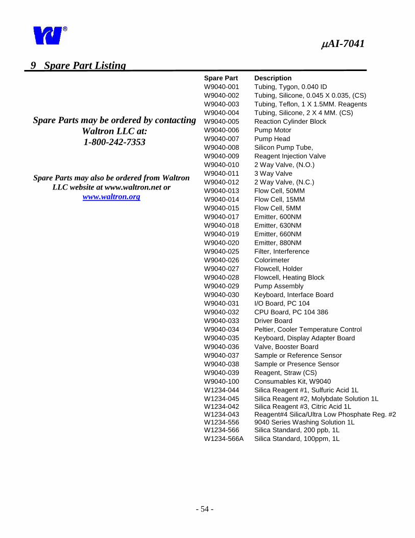
9 Spare Part Listing
Spare Parts may be ordered by contacting
Waltron LLC at:
1-800-242-7353
Spare Parts may also be ordered from Waltron
LLC website at www.waltron.net or
www.waltron.org
Spare Part Description
W9040-001 Tubing, Tygon, 0.040 ID
W9040-002 Tubing, Silicone, 0.045 X 0.035, (CS)
W9040-003 Tubing, Teflon, 1 X 1.5MM. Reagents
W9040-004 Tubing, Silicone, 2 X 4 MM. (CS)
W9040-005 Reaction Cylinder Block
W9040-006 Pump Motor
W9040-007 Pump Head
W9040-008 Silicon Pump Tube,
W9040-009 Reagent Injection Valve
W9040-010 2 Way Valve, (N.O.)
W9040-011 3 Way Valve
W9040-012 2 Way Valve, (N.C.)
W9040-013 Flow Cell, 50MM
W9040-014 Flow Cell, 15MM
W9040-015 Flow Cell, 5MM
W9040-017 Emitter, 600NM
W9040-018 Emitter, 630NM
W9040-019 Emitter, 660NM
W9040-020 Emitter, 880NM
W9040-025 Filter, Interference
W9040-026 Colorimeter
W9040-027 Flowcell, Holder
W9040-028 Flowcell, Heating Block
W9040-029 Pump Assembly
W9040-030 Keyboard, Interface Board
W9040-031 I/O Board, PC 104
W9040-032 CPU Board, PC 104 386
W9040-033 Driver Board
W9040-034 Peltier, Cooler Temperature Control
W9040-035 Keyboard, Display Adapter Board
W9040-036 Valve, Booster Board
W9040-037 Sample or Reference Sensor
W9040-038 Sample or Presence Sensor
W9040-039 Reagent, Straw (CS)
W9040-100 Consumables Kit, W9040
W1234-044 Silica Reagent #1, Sulfuric Acid 1L
W1234-045 Silica Reagent #2, Molybdate Solution 1L W1234-042 W1234-043
Silica Reagent #3, Citric Acid 1L Reagent#4 Silica/Ultra Low Phosphate Reg. #2
W1234-556 W1234-566
9040 Series Washing Solution 1L Silica Standard, 200 ppb, 1L
W1234-566A Silica Standard, 100ppm, 1L


![financialintegrity.orgfinancialintegrity.org/images/0/04/FI_Program... · Translate this page%PDF-1.5 %âãÏÓ 7041 0 obj endobj 7053 0 obj /Filter/FlateDecode/ID[]/Index[7041](https://img.pdfslide.us/doc/110x75/5b1a3d037f8b9a46258d39f4/-translate-this-pagepdf-15-aaio-7041-0-obj-endobj-7053-0-obj-filterflatedecodeidindex7041.jpg)