Embed Size (px)
Citation preview

Wall Design for Out of Plane Wind Loads
October, 2015
Day’s Overview
• Load Path Overview • Introduc9on to Codes & Standards • Diaphragm Design and Detailing • Shear Wall Design and Detailing • Prescrip9ve Design Op9ons for
Wood Systems • UpliG including Combined Shear • Wall Design • Mul9-‐Story Considera9ons
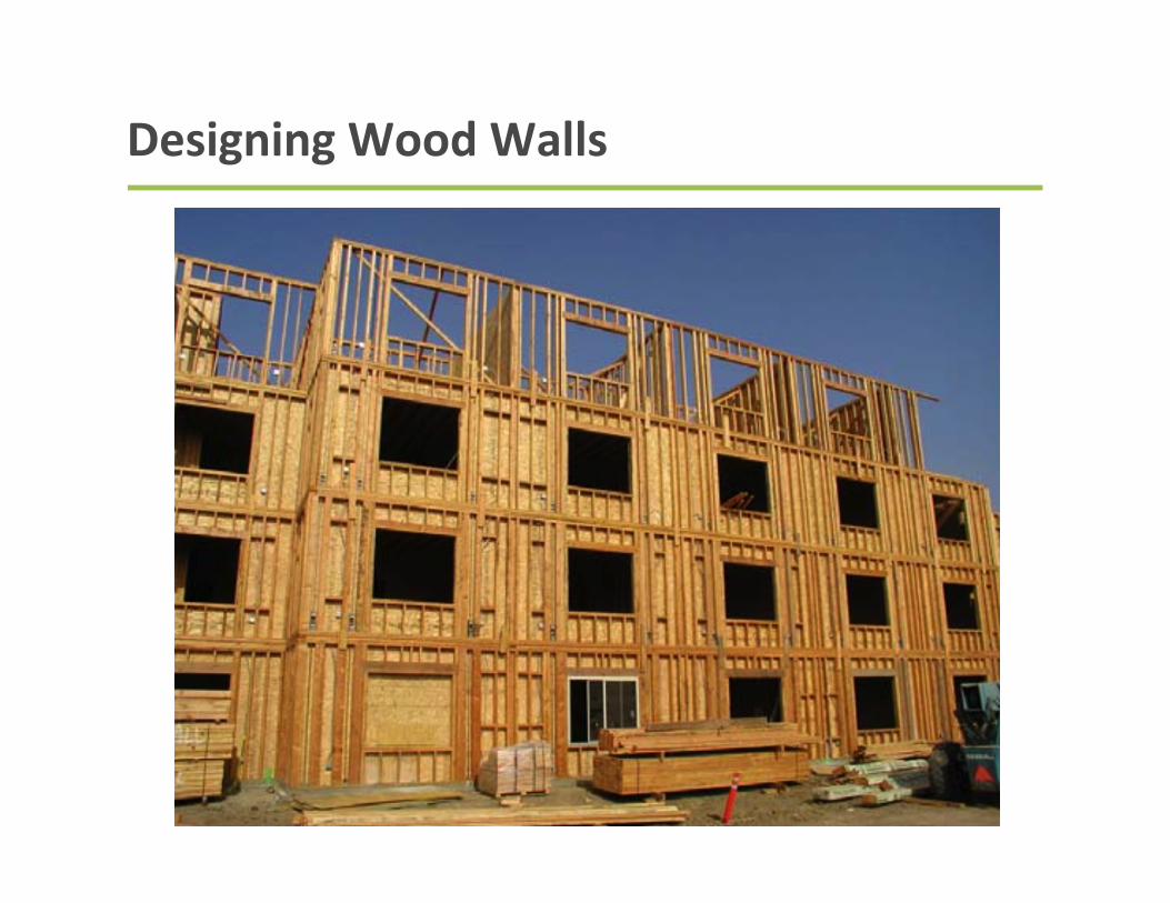
Designing Wood Walls
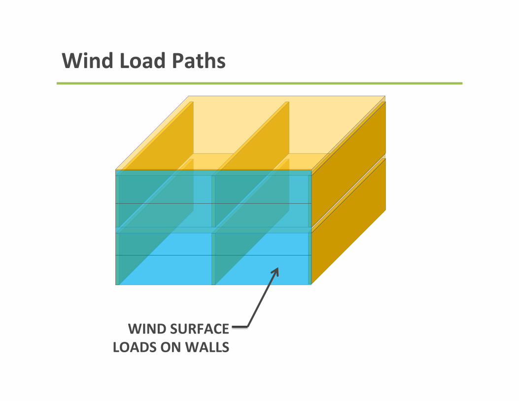
Wind Load Paths
WIND SURFACE LOADS ON WALLS
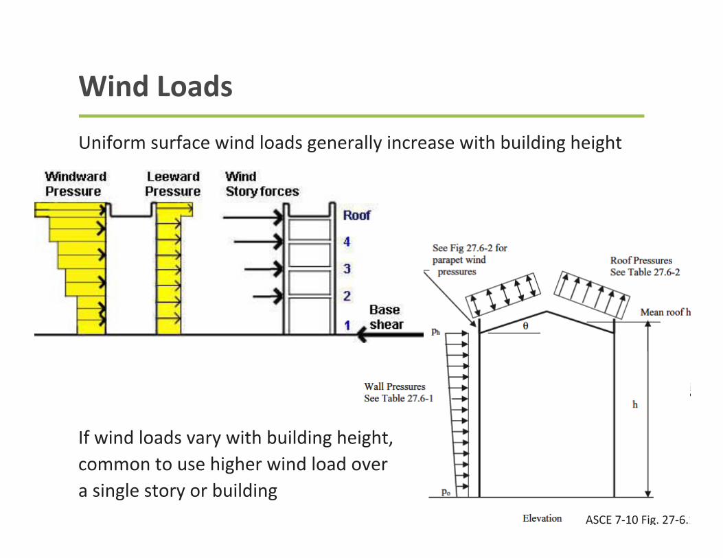
Wind Loads
Uniform surface wind loads generally increase with building height
ASCE 7-‐10 Fig. 27-‐6.1
If wind loads vary with building height, common to use higher wind load over a single story or building
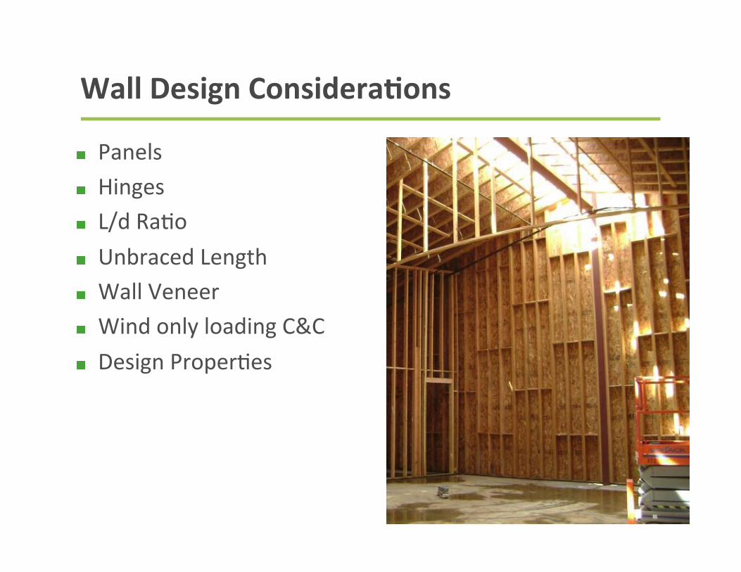
Panels Hinges L/d Ra9o Unbraced Length Wall Veneer Wind only loading C&C Design Proper9es
Wall Design ConsideraBons
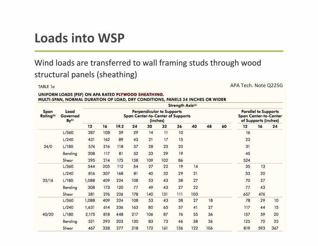
Loads into WSP
Wind loads are transferred to wall framing studs through wood structural panels (sheathing)
APA Tech. Note Q225G
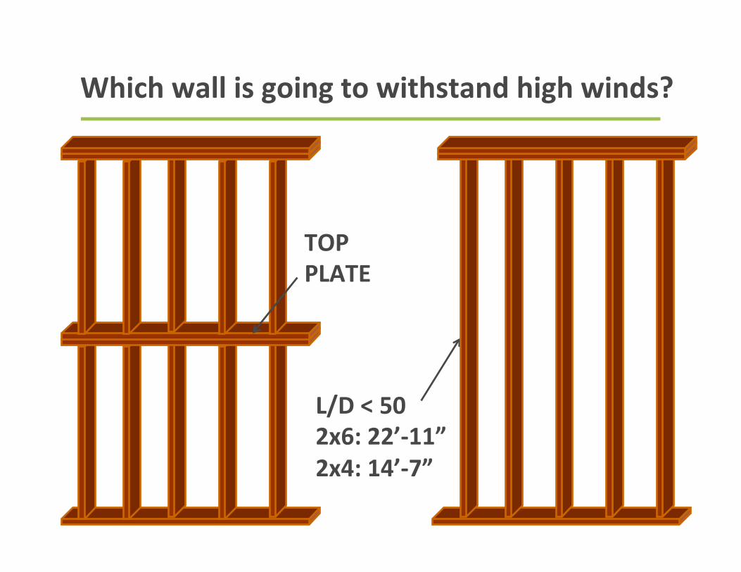
TOP PLATE
L/D < 50 2x6: 22’-‐11” 2x4: 14’-‐7”
Which wall is going to withstand high winds?
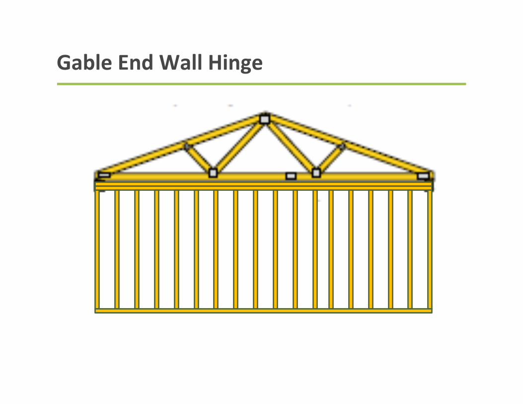
Gable End Wall Hinge
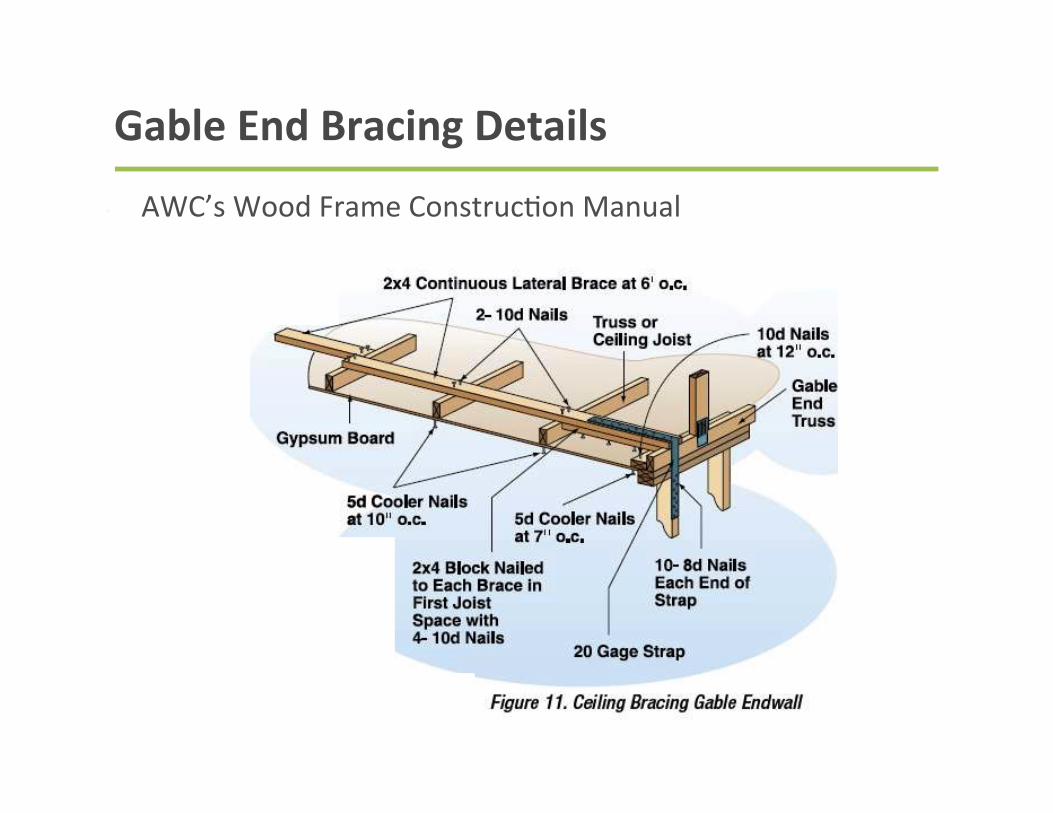
Gable End Bracing Details
• AWC’s Wood Frame Construc9on Manual
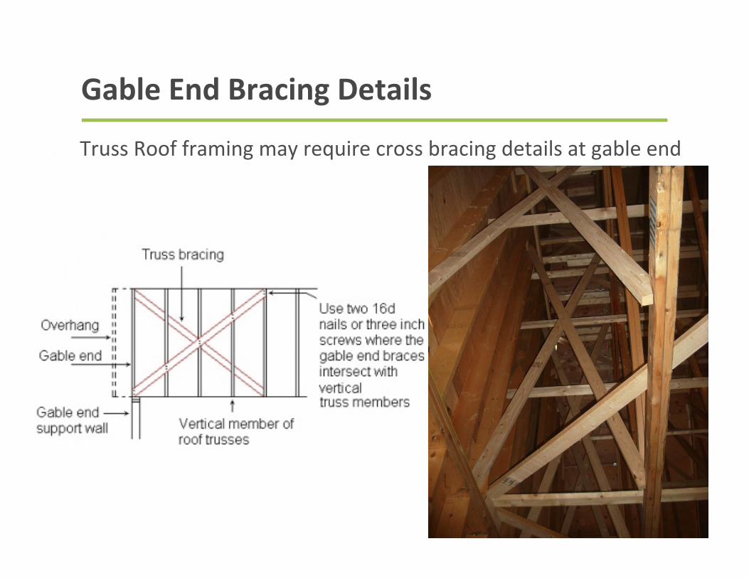
Gable End Bracing Details
• Truss Roof framing may require cross bracing details at gable end
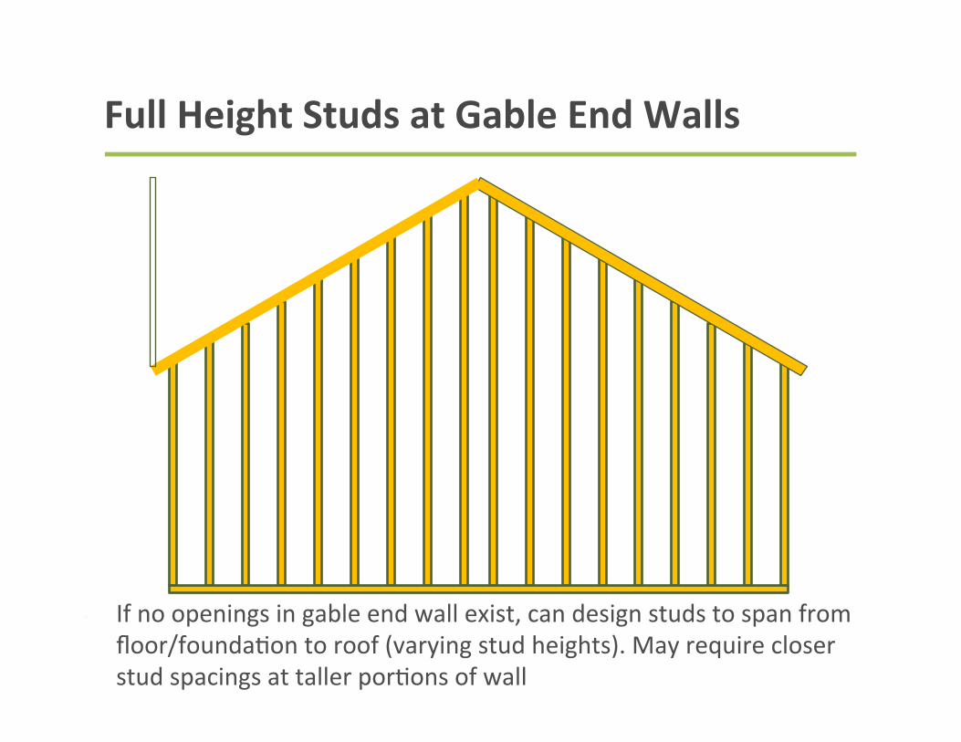
Full Height Studs at Gable End Walls
• If no openings in gable end wall exist, can design studs to span from floor/founda9on to roof (varying stud heights). May require closer stud spacings at taller por9ons of wall
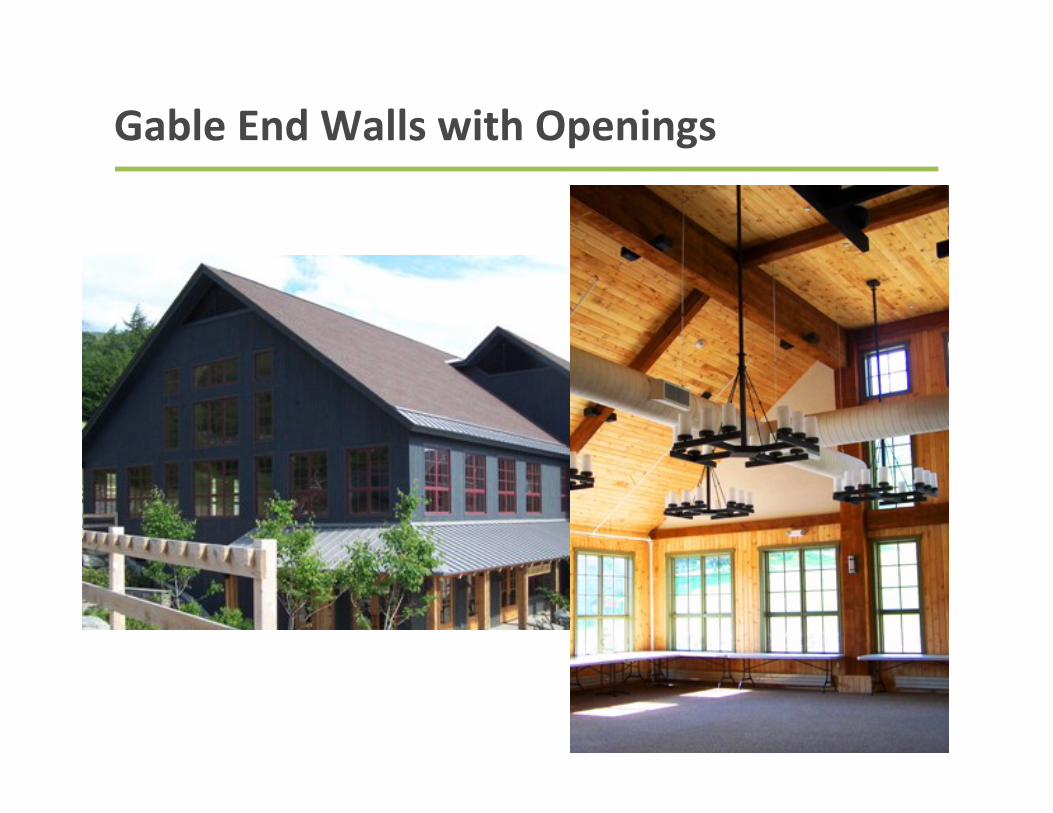
Gable End Walls with Openings
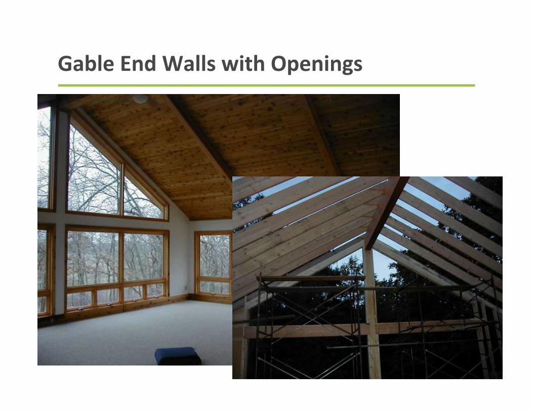
Gable End Walls with Openings
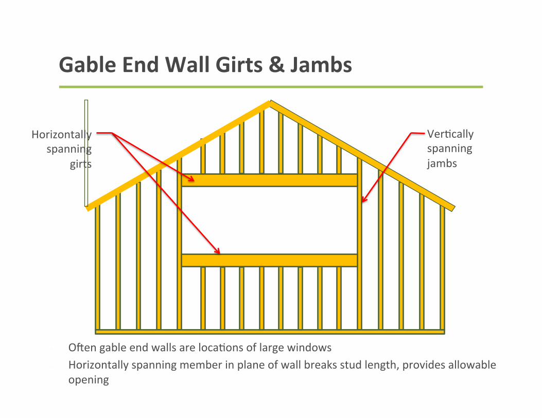
Gable End Wall Girts & Jambs
• OGen gable end walls are loca9ons of large windows • Horizontally spanning member in plane of wall breaks stud length, provides allowable
opening
Ver9cally spanning jambs
Horizontally spanning
girts
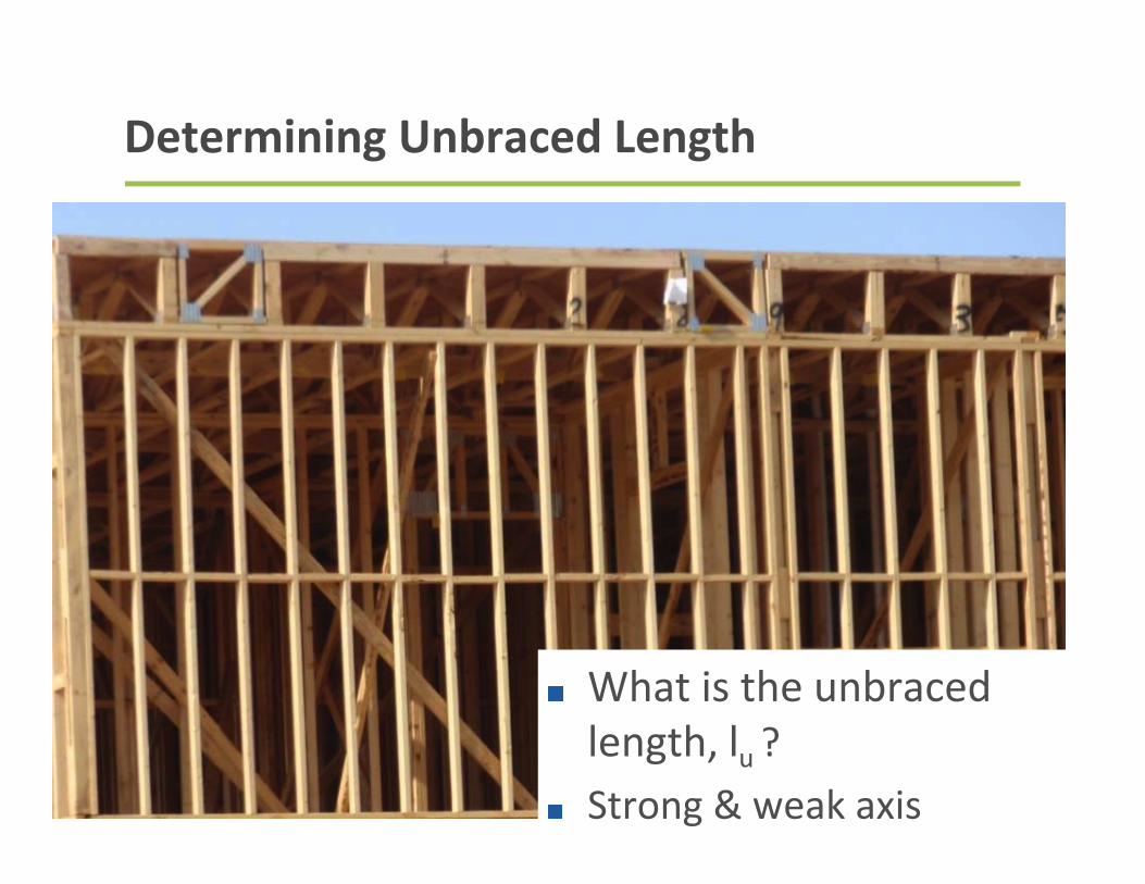
Determining Unbraced Length
What is the unbraced length, lu ? Strong & weak axis
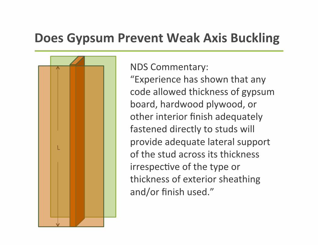
Does Gypsum Prevent Weak Axis Buckling
L
NDS Commentary: “Experience has shown that any code allowed thickness of gypsum board, hardwood plywood, or other interior finish adequately fastened directly to studs will provide adequate lateral support of the stud across its thickness irrespec9ve of the type or thickness of exterior sheathing and/or finish used.”
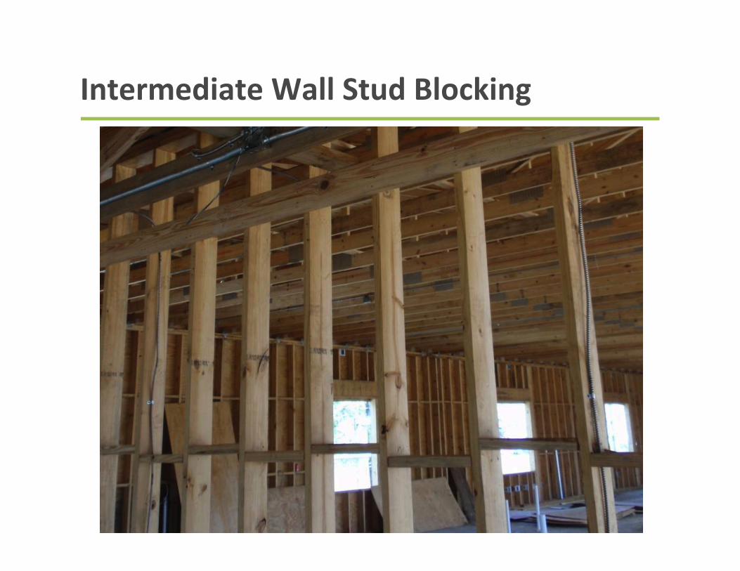
Intermediate Wall Stud Blocking
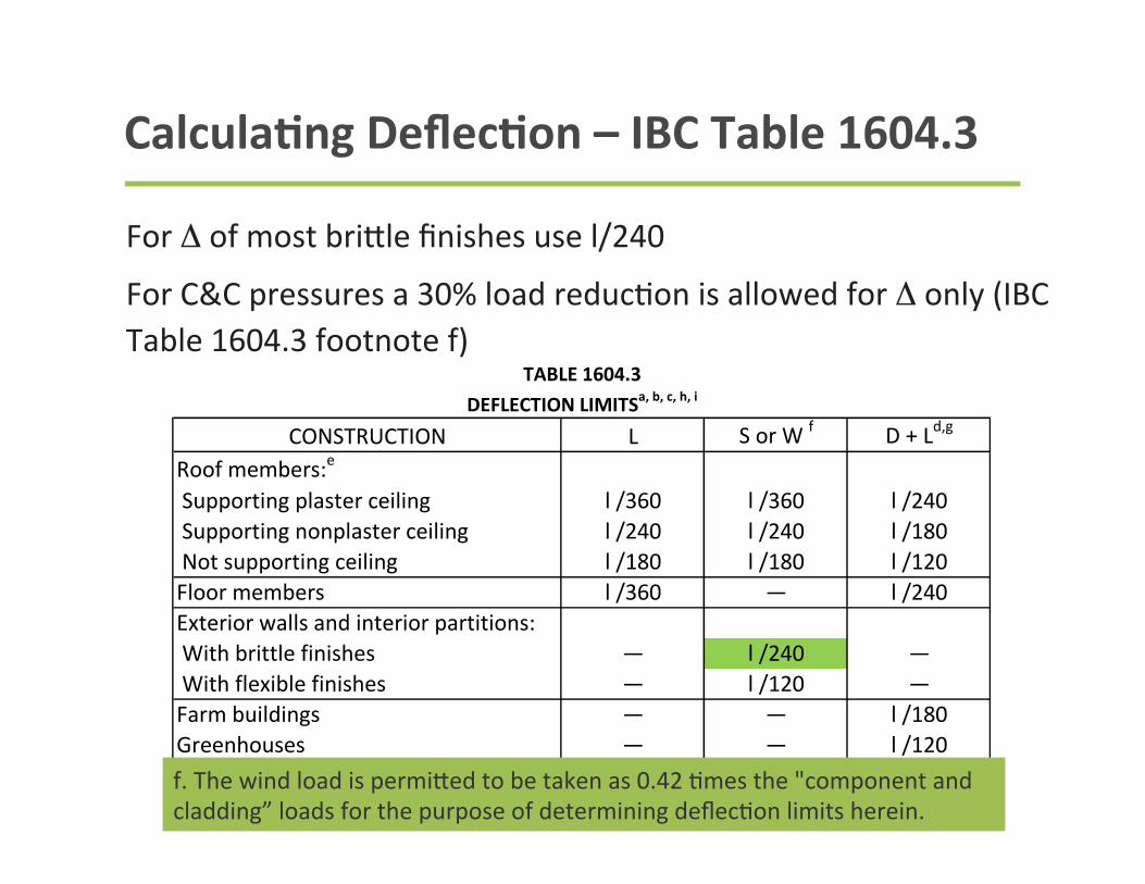
CalculaBng DeflecBon – IBC Table 1604.3
For Δ of most brifle finishes use l/240
For C&C pressures a 30% load reduc9on is allowed for Δ only (IBC Table 1604.3 footnote f)
CONSTRUCTION L S or W f D + Ld,g
Roof members:e
Supporting plaster ceiling l /360 l /360 l /240 Supporting nonplaster ceiling l /240 l /240 l /180 Not supporting ceiling l /180 l /180 l /120Floor members l /360 — l /240Exterior walls and interior partitions: With brittle finishes — l /240 — With flexible finishes — l /120 —Farm buildings — — l /180Greenhouses — — l /120
DEFLECTION LIMITSa, b, c, h, iTABLE 1604.3
f. The wind load is permitted to be taken as 0.7 times the “component and cladding” loads for the purpose of determining deflection limits herein.f. The wind load is permifed to be taken as 0.42 9mes the "component and cladding” loads for the purpose of determining deflec9on limits herein.
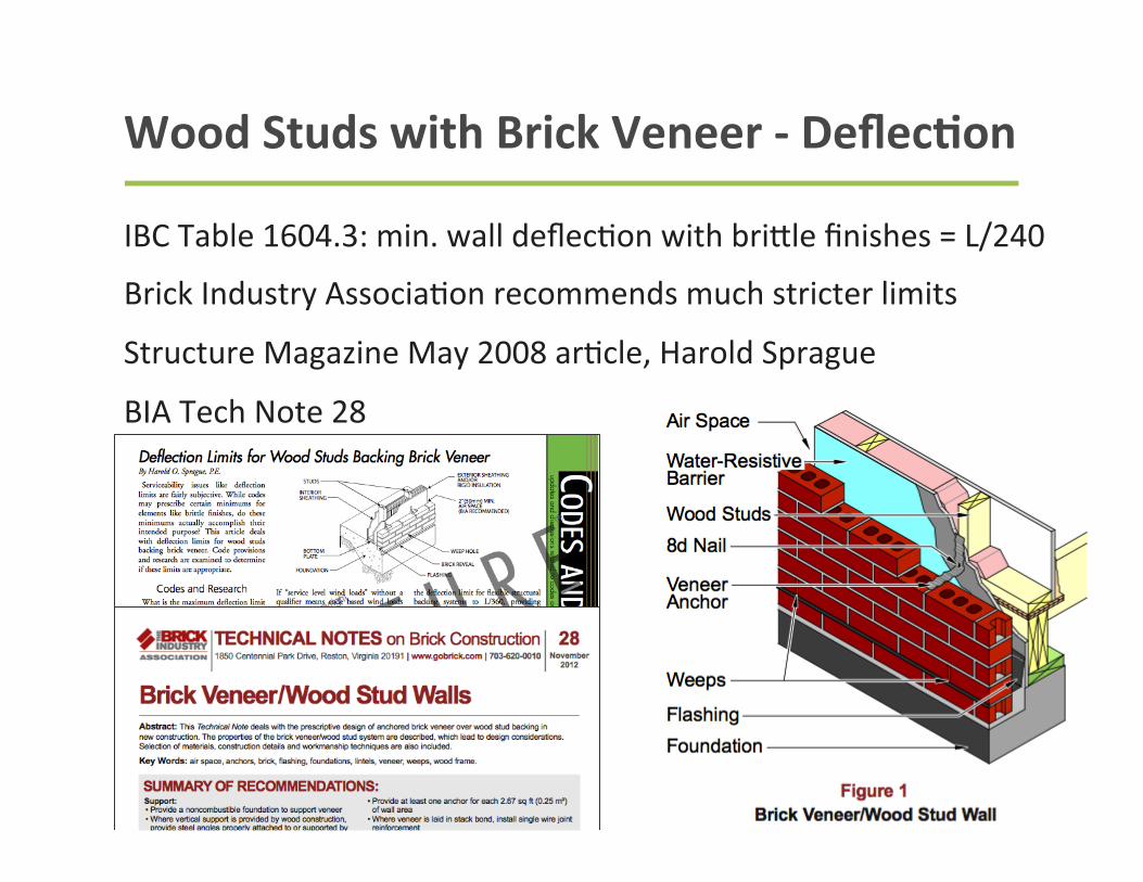
Wood Studs with Brick Veneer -‐ DeflecBon
IBC Table 1604.3: min. wall deflec9on with brifle finishes = L/240
Brick Industry Associa9on recommends much stricter limits
Structure Magazine May 2008 ar9cle, Harold Sprague
BIA Tech Note 28
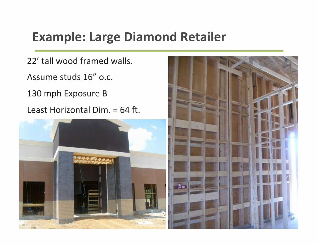
Example: Large Diamond Retailer
22’ tall wood framed walls.
Assume studs 16” o.c.
130 mph Exposure B
Least Horizontal Dim. = 64 G.
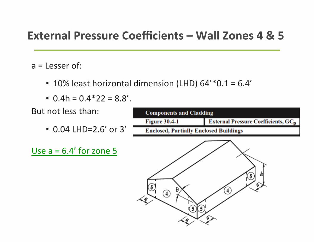
External Pressure Coefficients – Wall Zones 4 & 5
a = Lesser of:
• 10% least horizontal dimension (LHD) 64’*0.1 = 6.4’
• 0.4h = 0.4*22 = 8.8’. But not less than:
• 0.04 LHD=2.6’ or 3’
Use a = 6.4’ for zone 5
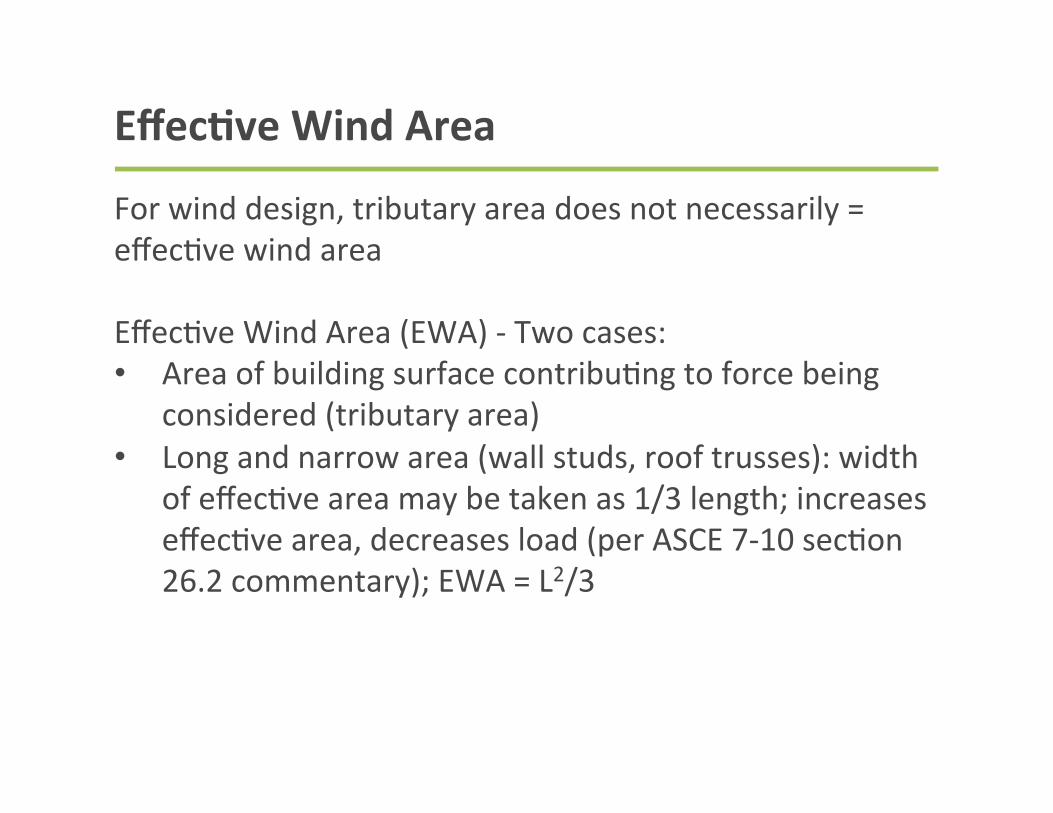
EffecBve Wind Area
For wind design, tributary area does not necessarily = effec9ve wind area Effec9ve Wind Area (EWA) -‐ Two cases: • Area of building surface contribu9ng to force being
considered (tributary area) • Long and narrow area (wall studs, roof trusses): width
of effec9ve area may be taken as 1/3 length; increases effec9ve area, decreases load (per ASCE 7-‐10 sec9on 26.2 commentary); EWA = L2/3
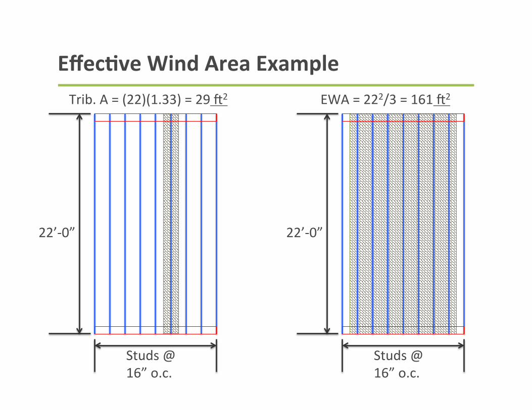
EffecBve Wind Area Example
22’-‐0”
Studs @ 16” o.c.
22’-‐0”
Studs @ 16” o.c.
Trib. A = (22)(1.33) = 29 G2 EWA = 222/3 = 161 G2
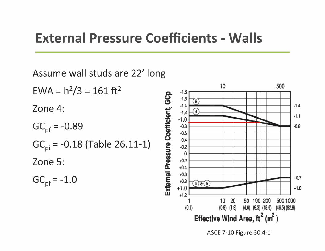
External Pressure Coefficients -‐ Walls
Assume wall studs are 22’ long
EWA = h2/3 = 161 G2
Zone 4:
GCpf = -‐0.89
GCpi = -‐0.18 (Table 26.11-‐1)
Zone 5:
GCpf = -‐1.0
ASCE 7-‐10 Figure 30.4-‐1
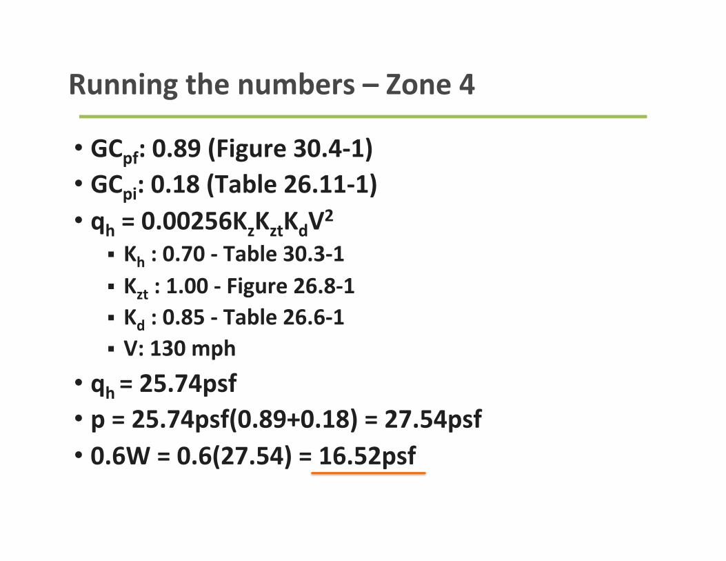
Running the numbers – Zone 4
• GCpf: 0.89 (Figure 30.4-‐1) • GCpi: 0.18 (Table 26.11-‐1) • qh = 0.00256KzKztKdV2
§ Kh : 0.70 -‐ Table 30.3-‐1
§ Kzt : 1.00 -‐ Figure 26.8-‐1 § Kd : 0.85 -‐ Table 26.6-‐1 § V: 130 mph
• qh = 25.74psf • p = 25.74psf(0.89+0.18) = 27.54psf • 0.6W = 0.6(27.54) = 16.52psf
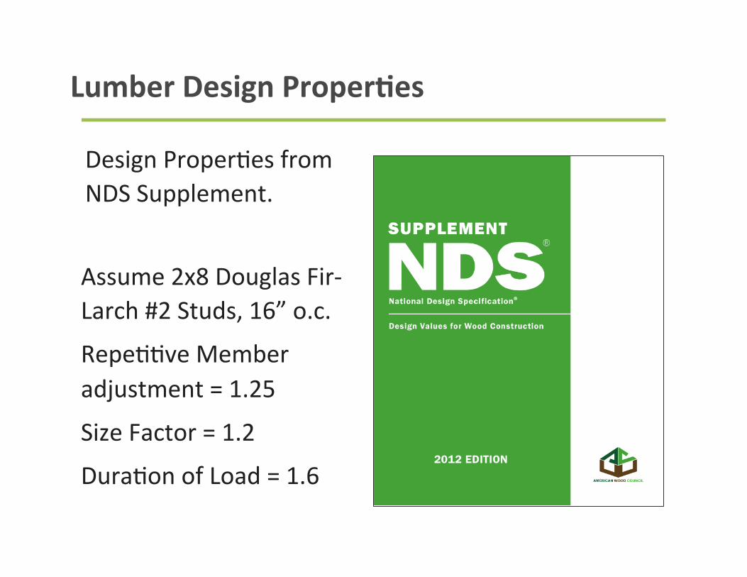
Lumber Design ProperBes
Design Proper9es from NDS Supplement.
Assume 2x8 Douglas Fir-‐Larch #2 Studs, 16” o.c.
Repe99ve Member adjustment = 1.25
Size Factor = 1.2
Dura9on of Load = 1.6
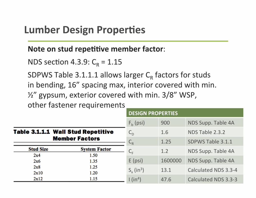
Lumber Design ProperBes
Note on stud repeBBve member factor: NDS sec9on 4.3.9: CR = 1.15 SDPWS Table 3.1.1.1 allows larger CR factors for studs in bending, 16” spacing max, interior covered with min. ½” gypsum, exterior covered with min. 3/8” WSP, other fastener requirements
DESIGN PROPERTIES
Fb (psi) 900 NDS Supp. Table 4A
CD 1.6 NDS Table 2.3.2
CR 1.25 SDPWS Table 3.1.1
CF 1.2 NDS Supp. Table 4A
E (psi) 1600000 NDS Supp. Table 4A
Sx (in3) 13.1 Calculated NDS 3.3-‐4
I (in4) 47.6 Calculated NDS 3.3-‐3
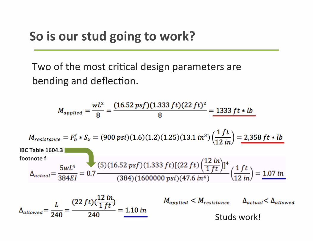
So is our stud going to work?
Two of the most cri9cal design parameters are bending and deflec9on.
Studs work!
IBC Table 1604.3 footnote f
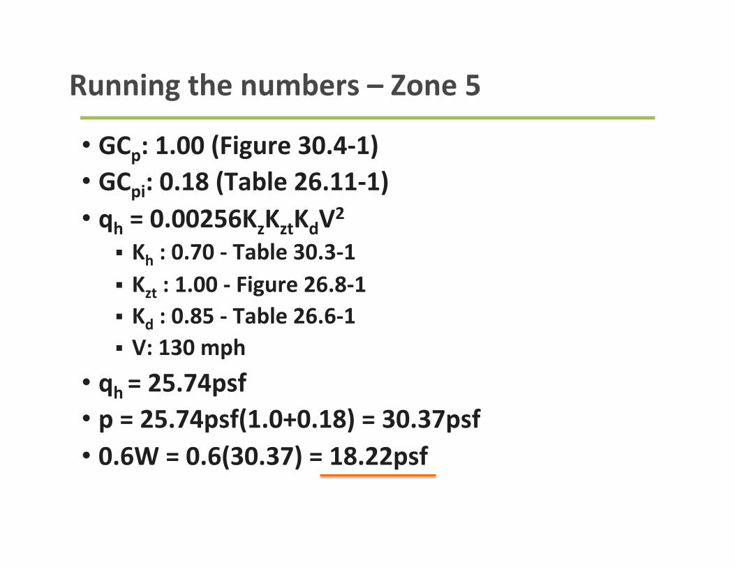
• GCp: 1.00 (Figure 30.4-‐1) • GCpi: 0.18 (Table 26.11-‐1) • qh = 0.00256KzKztKdV2
§ Kh : 0.70 -‐ Table 30.3-‐1
§ Kzt : 1.00 -‐ Figure 26.8-‐1 § Kd : 0.85 -‐ Table 26.6-‐1 § V: 130 mph
• qh = 25.74psf • p = 25.74psf(1.0+0.18) = 30.37psf • 0.6W = 0.6(30.37) = 18.22psf
Running the numbers – Zone 5
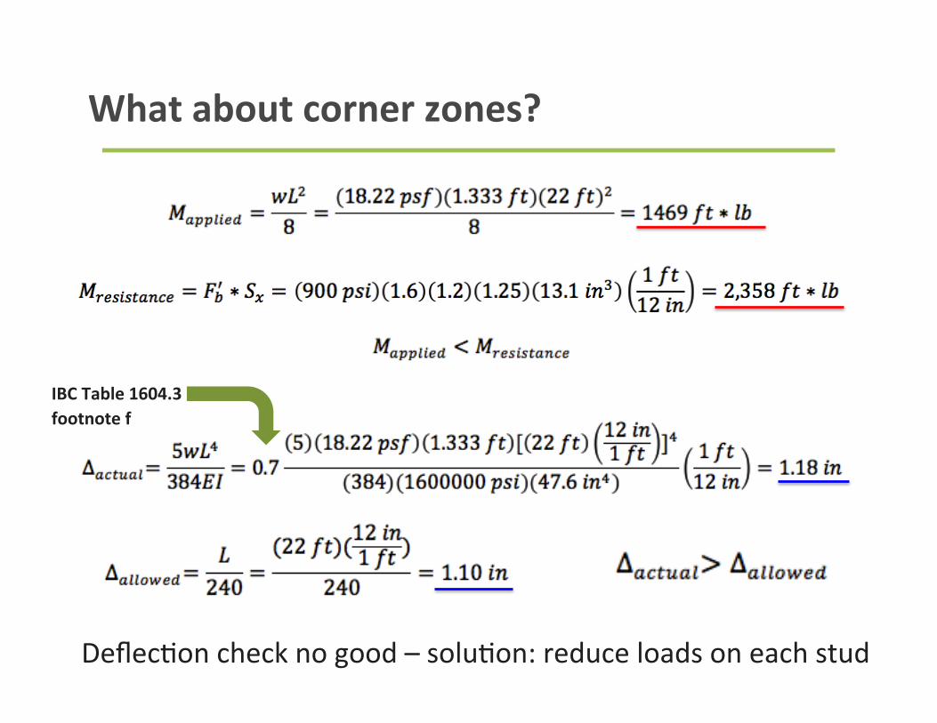
What about corner zones?
Deflec9on check no good – solu9on: reduce loads on each stud
IBC Table 1604.3 footnote f
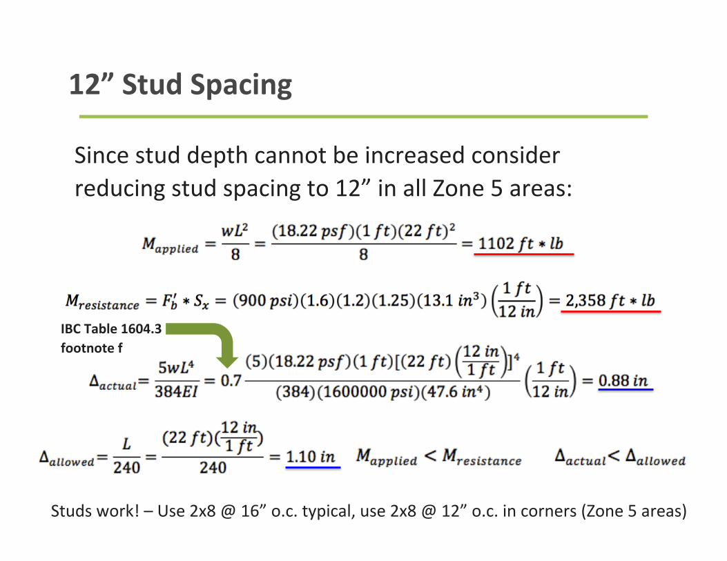
12” Stud Spacing
Since stud depth cannot be increased consider reducing stud spacing to 12” in all Zone 5 areas:
Studs work! – Use 2x8 @ 16” o.c. typical, use 2x8 @ 12” o.c. in corners (Zone 5 areas)
IBC Table 1604.3 footnote f
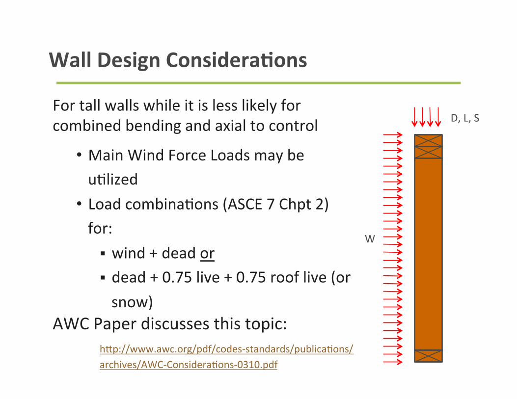
Wall Design ConsideraBons
For tall walls while it is less likely for combined bending and axial to control
• Main Wind Force Loads may be u9lized • Load combina9ons (ASCE 7 Chpt 2) for: § wind + dead or § dead + 0.75 live + 0.75 roof live (or snow)
AWC Paper discusses this topic: hfp://www.awc.org/pdf/codes-‐standards/publica9ons/archives/AWC-‐Considera9ons-‐0310.pdf
D, L, S
W
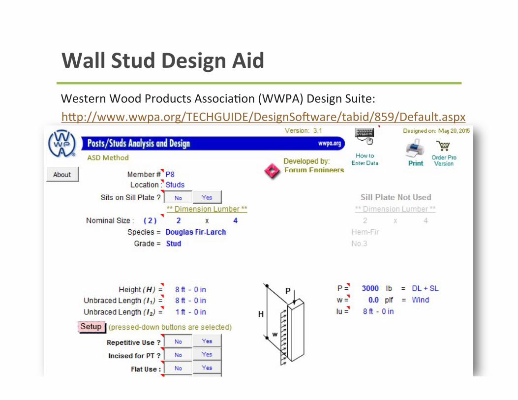
Wall Stud Design Aid Western Wood Products Associa9on (WWPA) Design Suite: hfp://www.wwpa.org/TECHGUIDE/DesignSoGware/tabid/859/Default.aspx

QuesBons?
Visit www.woodworks.org for more educaBonal materials, case studies, design examples, a project gallery, and more