Embed Size (px)
Citation preview
MIS-656
Models: WH301, WH361
WALL MOUNTEDPACKAGED HEAT PUMPINSTALLATION
INSTRUCTIONS
Manual No.: 2100-193KSupersedes: 2100-193JFile: Volume III, Tab 17Date: 05-13-02
Bard Manufacturing CompanyBryan, Ohio 43506
Since 1914. . .Moving ahead just as planned.
© Copyright 2002
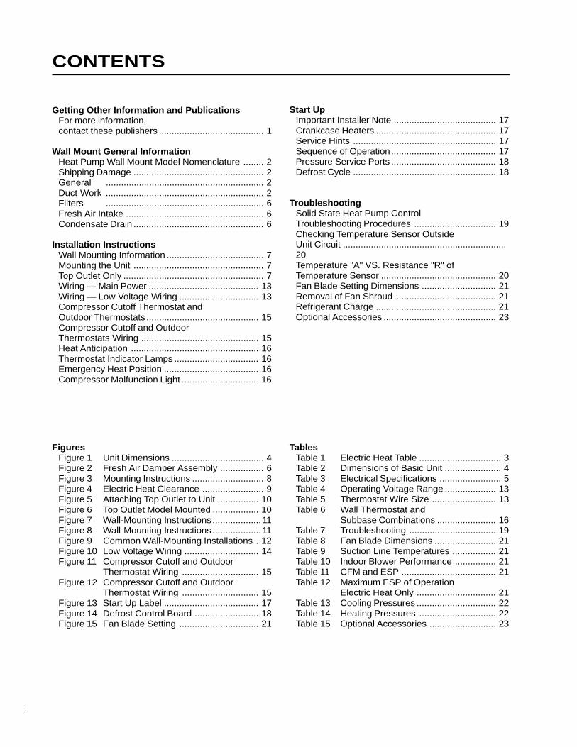
CONTENTS
i
FiguresFigure 1 Unit Dimensions .................................... 4Figure 2 Fresh Air Damper Assembly ................. 6Figure 3 Mounting Instructions ............................ 8Figure 4 Electric Heat Clearance ........................ 9Figure 5 Attaching Top Outlet to Unit ................ 10Figure 6 Top Outlet Model Mounted .................. 10Figure 7 Wall-Mounting Instructions ...................11Figure 8 Wall-Mounting Instructions ...................11Figure 9 Common Wall-Mounting Installations . 12Figure 10 Low Voltage Wiring ............................. 14Figure 11 Compressor Cutoff and Outdoor
Thermostat Wiring .............................. 15Figure 12 Compressor Cutoff and Outdoor
Thermostat Wiring .............................. 15Figure 13 Start Up Label ..................................... 17Figure 14 Defrost Control Board ......................... 18Figure 15 Fan Blade Setting ............................... 21
TablesTable 1 Electric Heat Table ................................ 3Table 2 Dimensions of Basic Unit ...................... 4Table 3 Electrical Specifications ........................ 5Table 4 Operating Voltage Range .................... 13Table 5 Thermostat Wire Size ......................... 13Table 6 Wall Thermostat and
Subbase Combinations ....................... 16Table 7 Troubleshooting .................................. 19Table 8 Fan Blade Dimensions ........................ 21Table 9 Suction Line Temperatures ................. 21Table 10 Indoor Blower Performance ................ 21Table 11 CFM and ESP ..................................... 21Table 12 Maximum ESP of Operation
Electric Heat Only ............................... 21Table 13 Cooling Pressures ............................... 22Table 14 Heating Pressures .............................. 22Table 15 Optional Accessories .......................... 23
Start UpImportant Installer Note ........................................ 17Crankcase Heaters ............................................... 17Service Hints ........................................................ 17Sequence of Operation......................................... 17Pressure Service Ports ......................................... 18Defrost Cycle ........................................................ 18
TroubleshootingSolid State Heat Pump ControlTroubleshooting Procedures ................................ 19Checking Temperature Sensor OutsideUnit Circuit ................................................................20Temperature "A" VS. Resistance "R" ofTemperature Sensor ............................................. 20Fan Blade Setting Dimensions ............................. 21Removal of Fan Shroud ........................................ 21Refrigerant Charge ............................................... 21Optional Accessories ............................................ 23
Getting Other Information and PublicationsFor more information,contact these publishers ......................................... 1
Wall Mount General InformationHeat Pump Wall Mount Model Nomenclature ........ 2Shipping Damage ................................................... 2General .............................................................. 2Duct Work .............................................................. 2Filters .............................................................. 6Fresh Air Intake ...................................................... 6Condensate Drain ................................................... 6
Installation InstructionsWall Mounting Information ...................................... 7Mounting the Unit ................................................... 7Top Outlet Only ....................................................... 7Wiring — Main Power ........................................... 13Wiring — Low Voltage Wiring ............................... 13Compressor Cutoff Thermostat andOutdoor Thermostats ............................................ 15Compressor Cutoff and OutdoorThermostats Wiring .............................................. 15Heat Anticipation .................................................. 16Thermostat Indicator Lamps ................................. 16Emergency Heat Position ..................................... 16Compressor Malfunction Light .............................. 16

Manual 2100-193Page 1
Getting Other Information and Publications
These publications can help you install the airconditioner or heat pump. You can usually find these atyour local library or purchase them directly from thepublisher. Be sure to consult current edition of eachstandard.
National Electrical Code ....................... ANSI/NFPA 70
Standard for the Installation ............... ANSI/NFPA 90Aof Air Conditioning andVentilating Systems
Standard for Warm Air ....................... ANSI/NFPA 90BHeating and AirConditioning Systems
Load Calculation for ............................. ACCA Manual JResidential Winter andSummer Air Conditioning
Duct Design for Residential ............... ACCA Manual DWinter and Summer AirConditioning and EquipmentSelection
For more information, contact thesepublishers:
ACCA Air Conditioning Contractors of America1712 New Hampshire Avenue NWWashington, DC 20009Telephone: (202) 483-9370Fax: (202) 234-4721
ANSI American National Standards Institute11 West Street, 13th FloorNew York, NY 10036Telephone: (212) 642-4900Fax: (212) 302-1286
ASHRAE American Society of Heating Refrigerating,and Air Conditioning Engineers, Inc.1791 Tullie Circle, N.E.Atlanta, GA 30329-2305Telephone: (404) 636-8400Fax: (404) 321-5478
NFPA National Fire Protection AssociationBatterymarch ParkP.O. Box 9101Quincy, MA 02269-9901Telephone: (800) 344-3555Fax: (617) 984-7057
Manufactured under the following U.S. patent numbers:
5,485,878; 5,301,744; 5,002,116; 4,924,934;4,875,520; 4,825,936
Manual 2100-193Page 2
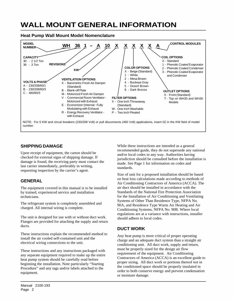
WALL MOUNT GENERAL INFORMATIONHeat Pump Wall Mount Model Nomenclature
WH 36 1 – A 10 X X X X X A
VOLTS & PHASEA - 230/208/60/1B - 230/208/60/3C - 460/60/3
MODELNUMBER
REVISIONS
CAPACITY30 - 2 1/2 Ton36 - 3 Ton
KW
VENTILATION OPTIONSX - Barometric Fresh Air Damper
(Standard)B - Blank-off PlateM - Motorized Fresh Air DamperV - Commercial Room Ventilator -
Motorized with ExhaustE - Economizer (Internal - Fully
Modulating with ExhaustR - Energy Recovery Ventilator -
with Exhaust
FILTER OPTIONSX - One Inch Throwaway
(Standard)W- One Inch WashableP - Two Inch Pleated
COLOR OPTIONSX - Beige (Standard)1 - White2 - Mesa Brown4 - Buckeye Gray5 - Desert Brown8 - Dark Bronze
CONTROL MODULES
COIL OPTIONS X - Standard 1 - Phenolic Coated Evaporator 2 - Phenolic Coated Condenser 3 - Phenolic Coated Evaporator
and Condenser
OUTLET OPTIONS X - Front (Standard) T - Top on WH30 and WH36
Models
NOTE: For 0 KW and circuit breakers (230/208 Volt) or pull disconnects (460 Volt) applications, insert 0Z in the KW field of modelnumber.
SHIPPING DAMAGEUpon receipt of equipment, the carton should bechecked for external signs of shipping damage. Ifdamage is found, the receiving party must contact thelast carrier immediately, preferably in writing,requesting inspection by the carrier’s agent.
GENERAL
The equipment covered in this manual is to be installedby trained, experienced service and installationtechnicians.
The refrigerant system is completely assembled andcharged. All internal wiring is complete.
The unit is designed for use with or without duct work.Flanges are provided for attaching the supply and returnducts.
These instructions explain the recommended method toinstall the air cooled self-contained unit and theelectrical wiring connections to the unit.
These instructions and any instructions packaged withany separate equipment required to make up the entireheat pump system should be carefully read beforebeginning the installation. Note particularly “StartingProcedure” and any tags and/or labels attached to theequipment.
While these instructions are intended as a generalrecommended guide, they do not supersede any nationaland/or local codes in any way. Authorities havingjurisdiction should be consulted before the installation ismade. See Page 1 for information on codes andstandards.
Size of unit for a proposed installation should be basedon heat loss calculations made according to methods ofAir Conditioning Contractors of America (ACCA). Theair duct should be installed in accordance with theStandards of the National Fire Protection Associationfor the Installation of Air Conditioning and VentilatingSystems of Other Than Residence Type, NFPA No.90A, and Residence Type Warm Air Heating and AirConditioning Systems, NFPA No. 90B. Where localregulations are at a variance with instructions, installershould adhere to local codes.
DUCT WORK
Any heat pump is more critical of proper operatingcharge and an adequate duct system than a straight airconditioning unit. All duct work, supply and return,must be properly sized for the design air flowrequirement of the equipment. Air ConditioningContractors of America (ACCA) is an excellent guide toproper sizing. All duct work or portions thereof not inthe conditioned space should be properly insulated inorder to both conserve energy and prevent condensationor moisture damage.
Manual 2100-193
Page 3
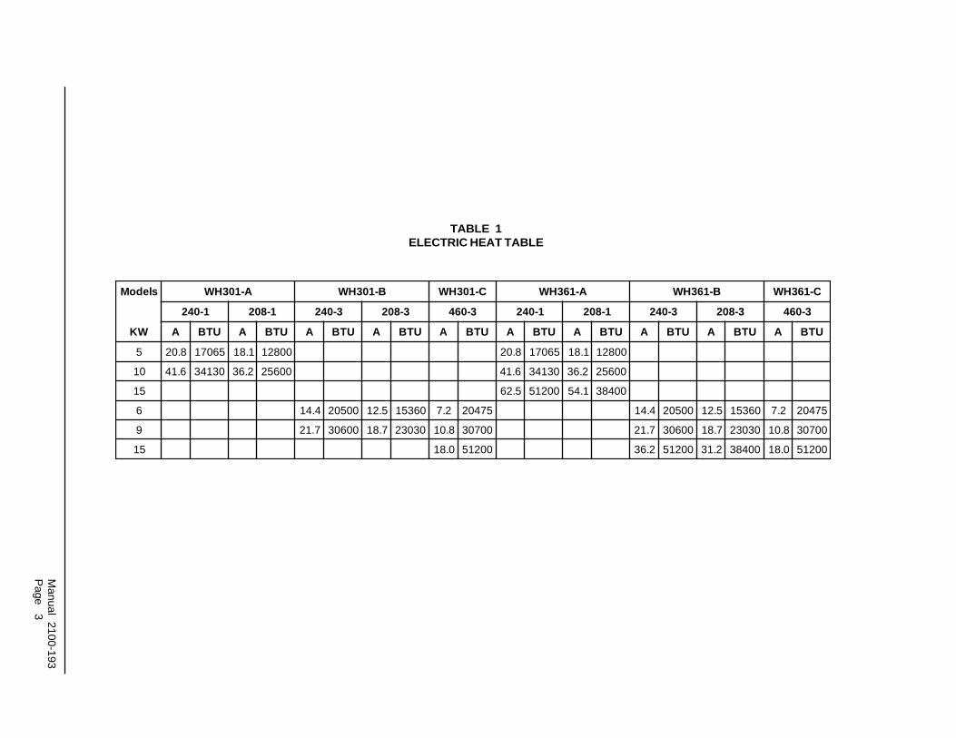
TABLE 1ELECTRIC HEAT TABLE
sledoM A-103HW B-103HW C-103HW A-163HW B-163HW C-163HW
1-042 1-802 3-042 3-802 3-064 1-042 1-802 3-042 3-802 3-064
WK A UTB A UTB A UTB A UTB A UTB A UTB A UTB A UTB A UTB A UTB
5 8.02 56071 1.81 00821 8.02 56071 1.81 00821
01 6.14 03143 2.63 00652 6.14 03143 2.63 00652
51 5.26 00215 1.45 00483
6 4.41 00502 5.21 06351 2.7 57402 4.41 00502 5.21 06351 2.7 57402
9 7.12 00603 7.81 03032 8.01 00703 7.12 00603 7.81 03032 8.01 00703
51 0.81 00215 2.63 00215 2.13 00483 0.81 00215

Manual 2100-193
Page 4
MIS-1262
FIGURE 1UNIT DIMENSIONS
FRONT VIEW BACK VIEWSIDE VIEW
* Optional top outlet (factory installed only) for WH30 and WH36 models only.
TABLE 2DIMENSIONS OF BASIC UNIT (Nominal)
ledoMhtdiW)W(
htpeD)D(
thgieH)H(
ylppuS nruteR
E F G I J K L M N O P Q R S TA B C B
03HW63HW
002.83 521.71 365.07 88.7 88.72 88.31 88.72 00.04 05.81 57.52 39.71 57.62 57.82 52.92 00.72 57.2 91.93 57.22 41.9 91.4 00.21 00.5

Manual 2100-193
Page 5
TABLE 3ELECTRICAL SPECIFICATIONS
Maximum size of the time delay fuse or HACR type circuit breaker for protection of field wiring conductors.
Based on 75° copper wire. All wiring must conform to the National Electrical Code and all local codes.
Maximum KW that can operate with heat pump on
These "Minimum Circuit Ampacity" values are to be used for sizing the field power conductors. Refer to the National ElectricCode (latest revision), Article 310 for power conductor sizing. CAUTION: When more than one field power conductor circuit isrun through one conduit, the conductors must be derated. Pay special attention to note 8 of table 310 regarding AmpacityAdjustment Factors when more than three conductors are in a raceway.
Not available in top outlet version�
�
�
�
�
ledoM detaRdnAstloV
esahP
.oNdleiF
rewoPstiucriC
�
muminiMtiucriCyticapmA
�
mumixaMlanretxE
roesuFtiucriCrekaerB
�
dleiFrewoP
eriWeziS
�
dnuorGeriWeziS
�
muminiMtiucriCyticapmA
�
mumixaMesuFlanretxE
tiucriCrorekaerB
�
rewoPdleiFeziSeriW
�
dnuorGeziSeriW
ATKC BTKC ATKC BTKC ATKC BTKC ATKC BTKC
Z0A-,00A-103HW50A-
� 01A-1-802/032
111
420567
530508
884
0101
8
------
05
------
62
------
05
------
03
------
8
------
01
------
01
------
01
Z0B-,00B-103HW� 60B-� 90B-
3-802/032111
917364
520405
0188
010101
---------
---------
---------
---------
---------
---------
---------
---------
Z0C-,00C-103HW� 60C-� 90C-� 51C-
3-064
1111
01914262
51025203
41210101
41210101
------------
------------
------------
------------
------------
------------
------------
------------
Z0A-,00A-163HW50A-
� 01A-� 51A-
1-802/032
11
2ro12ro1
72359738
04060809
01644
0101
88
------
3535
------
6225
------
0606
------
0306
------
66
------
016
------
0101
------
0101
Z0B-,00B-163HW� 60B-� 90B-� 51B-
3-802/032
1111
02837405
52040505
01888
01010101
------------
------------
------------
------------
------------
------------
------------
------------
Z0C-,00C-163HW� 60C-� 90C-� 51C-
3-064
1111
11025262
51025203
41210101
41210101
------------
------------
------------
------------
------------
------------
------------
------------

Manual 2100-193Page 6
FRESH AIR INTAKE
All units are built with fresh air inlet slots punched inthe service panel.
If the unit is equipped with a fresh air damper assembly,the assembly is shipped already attached to the unit.The damper blade is locked in the closed position. Toallow the damper to operate, the maximum andminimum blade position stops must be installed. SeeFigure 2.
All capacity, efficiency and cost of operationinformation as required for Department of Energy“Energyguide” Fact Sheets is based upon the fresh airblank-off plate in place and is recommended formaximum energy efficiency.
The blank-off plate is available upon request from thefactory and is installed in place of the fresh air dampershipped with each unit.
Any grille that meets the 5/8 inch louver criteria may beused. It is recommended that Bard Return Air Grille KitRG-2 through RG-5 or RFG-2 through RFG-5 beinstalled when no return duct is used. Contactdistributor or factory for ordering information. If usinga return air filter grille, filters must be of sufficient sizeto allow a maximum velocity of 400 fpm.
NOTE: If no return air duct is used, applicableinstallation codes may limit this cabinet toinstallation only in a single story structure.
FILTERS
A one (1) inch throwaway filter is supplied with eachunit. The filter slides into position making it easy toservice. This filter can be serviced from the outside byremoving the service door. A one (1) inch washablefilter and a two (2) inch pleated filter are also availableas optional accessories. The internal filter brackets areadjustable to accommodate the two inch filter byloosening two (2) screws in each bracket assembly andsliding the brackets apart to the required width andretightening the four (4) screws.
Refer to Table 12 for maximum static pressureavailable for duct design.
Design the duct work according to methods given by theAir Conditioning Contractors of America (ACCA).When duct runs through unheated spaces, it should beinsulated with a minimum of one inch of insulation.Use insulation with a vapor barrier on the outside of theinsulation. Flexible joints should be used to connect theduct work to the equipment in order to keep the noisetransmission to a minimum.
A 1/4 inch clearance to combustible material for thefirst three (3) feet of duct attached to the outlet airframe is required. See Wall Mounting Instructions andFigures 3 and 4 for further details.
Ducts through the walls must be insulated and all jointstaped or sealed to prevent air or moisture entering thewall cavity.
CONDENSATE DRAINA plastic drain hose extends from the drain pan at thetop of the unit down to the unit base. There areopenings in the unit base for the drain hose to passthrough. In the event the drain hose is connected to adrain system of some type, it must be an open or ventedtype system to assure proper drainage.
BLADE IS LOCKEDCLOSED FORSHIPPING
FIGURE 2FRESH AIR DAMPER ASSEMBLY
MIS-938
CAUTIONSome installations may not require anyreturn air duct. A metallic return air grille isrequired with installations not requiring areturn air duct. The spacing betweenlouvers on the grille shall not be larger than5/8 inches.

Manual 2100-193Page 7
INSTALLATION INSTRUCTIONS
3. Concrete block walls must be thoroughly inspected toinsure that they are capable of carrying the weight ofthe unit installed.
MOUNTING THE UNIT
1. These units are secured by wall mounting bracketswhich secure the unit to the outside wall surface atboth sides. A bottom mounting bracket is providedfor ease of installation, but is not required.
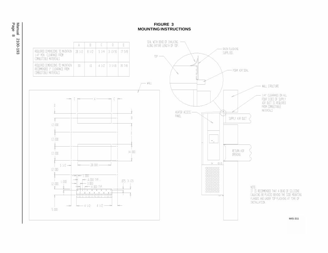
2. The unit itself is suitable for “0” inch clearance butthe supply air duct flange and the first 3 feet ofsupply air duct require a minimum of 1/4 inchclearance to combustible material. If a combustiblewall, use a minimum of 28-1/2" x 8-1/2" dimensionsfor sizing. However, it is generally recommended thata 1 inch clearance is used for ease of installation andmaintaining the required clearance to combustiblematerial. The supply air opening would then be 30" x10". See Figures 3, 4, 5 and 6 for details.
WARNINGFire hazard can result if 1/4 inch clearanceto combustible materials for supply air ductis not maintained. See Figure 3.
2. On wood-frame walls, the wall construction must bestrong and rigid enough to carry the weight of theunit without transmitting any unit vibration.
WALL MOUNTING INFORMATION
1. Two holes, for the supply and return air openings,must be cut through the wall as shown in Figure 3.
3. Locate and mark lag bolt locations and bottommounting bracket location. See Figure 3.
4. Mount bottom mounting bracket, if used.
5. Hook top rain flashing under back bend of top. Toprain flashing is shipped secured to the back of theunit on the right side.
6. Position unit in opening and secure with 5/16 lagbolts; use 7/8 inch diameter flat washers on the lagbolts.
7. Secure rain flashing to wall and caulk across entirelength of top. See Figure 3.
8. For additional mounting rigidity, the return air andsupply air frames or collars can be drilled andscrewed or welded to the structural wall itself(depending upon wall construction). Be sure toobserve required clearance if combustible wall.
9. On side by side installations, maintain a minimum of20 inches clearance on right side to allow access toheat strips and control panel and to allow properairflow to the outdoor coil. Additional clearance maybe required to meet local or national codes.
TOP OUTLET ONLY
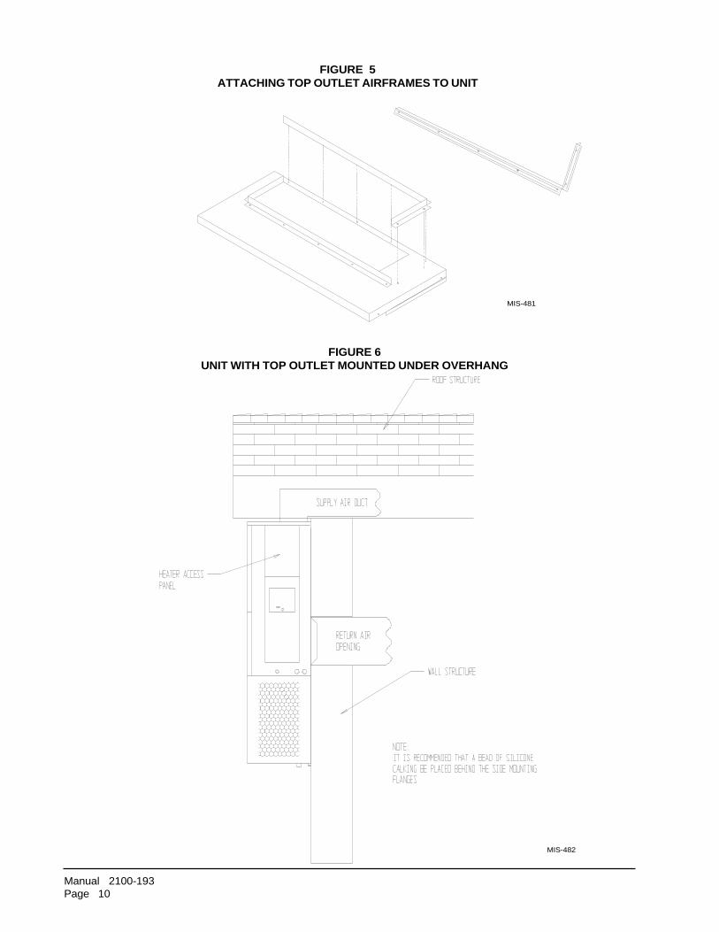
1. Remove airframe angles from the back of the unit.
2. Coat angles with two 1/8" beads of silicone as shown.Silicone is shipped in the control panel. See Figure 5.
3. Secure angles to the top of the unit with 14 screwsprovided. Use prepunched holes provided. Do notrelocate. See Figure 5.
4. After installation of duct work, seal around airframeand duct work to provide a rain tight seal.
5. It is strongly recommended, but not required, that thisunit be installed under a soffit area large enough toshield the top of the unit. See Figure 6.
WARNINGFailure to provide the 1/4 inch clearancebetween the supply duct and a combustiblesurface for the first 3 feet of duct can resultin fire.
Manual 2100-193
Page 8
FIGURE 3MOUNTING INSTRUCTIONS
MIS-311

Manual 2100-193Page 9
Side section view of supply air duct for wall mounted unit showing 1/4" clearance to combustible surfaces.
FIGURE 4ELECTRIC HEAT CLEARANCE
WARNINGA minimum of 1/4" clearance must be maintained between thesupply air duct and combustible materials. This is required forthe fist three (3) feet of ducting.
It is important to insure that the 1/4" minimum spacing ismaintained at all points.
Failure to do this could result in overheating the combustiblematerial and may result in a fire.
MIS-277
Manual 2100-193Page 10
FIGURE 5ATTACHING TOP OUTLET AIRFRAMES TO UNIT
MIS-481
FIGURE 6UNIT WITH TOP OUTLET MOUNTED UNDER OVERHANG
MIS-482
Manual 2100-193Page 11
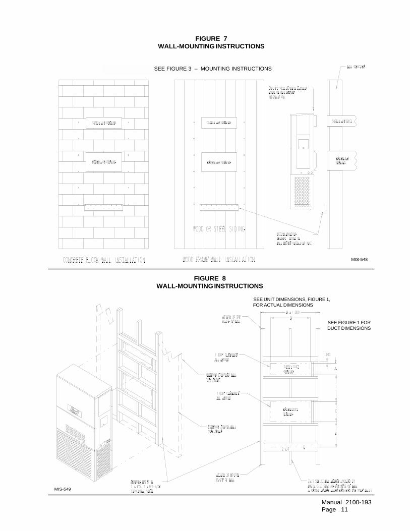
FIGURE 7WALL-MOUNTING INSTRUCTIONS
MIS-549
FIGURE 8WALL-MOUNTING INSTRUCTIONS
MIS-548
SEE FIGURE 3 – MOUNTING INSTRUCTIONS
SEE UNIT DIMENSIONS, FIGURE 1,FOR ACTUAL DIMENSIONS
SEE FIGURE 1 FORDUCT DIMENSIONS
Manual 2100-193Page 12
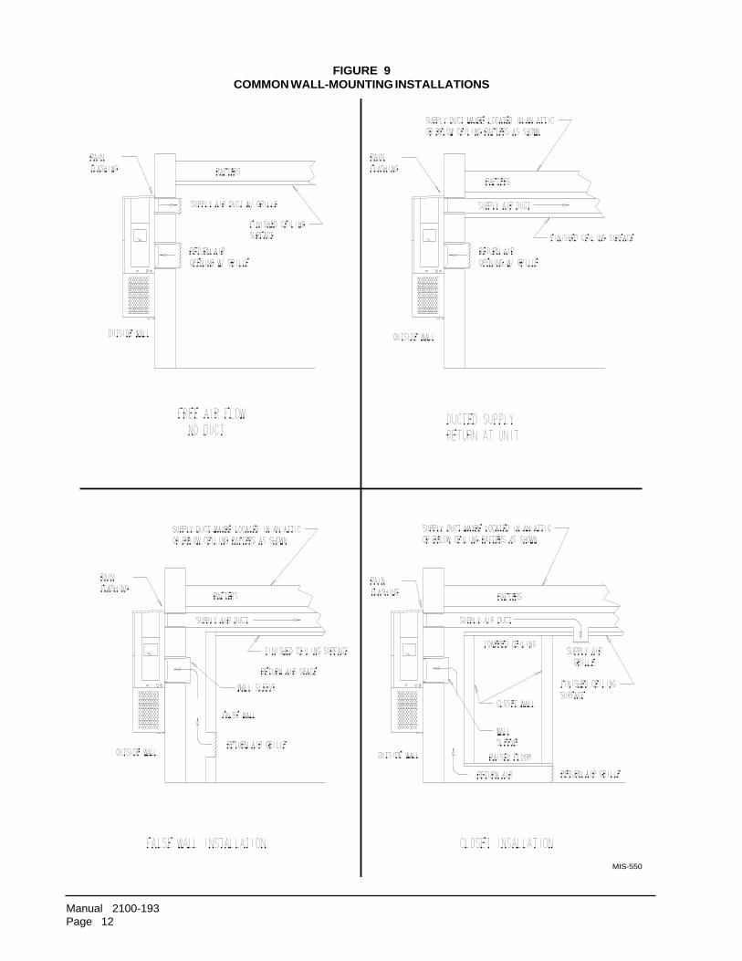
MIS-550
FIGURE 9COMMON WALL-MOUNTING INSTALLATIONS
Manual 2100-193Page 13
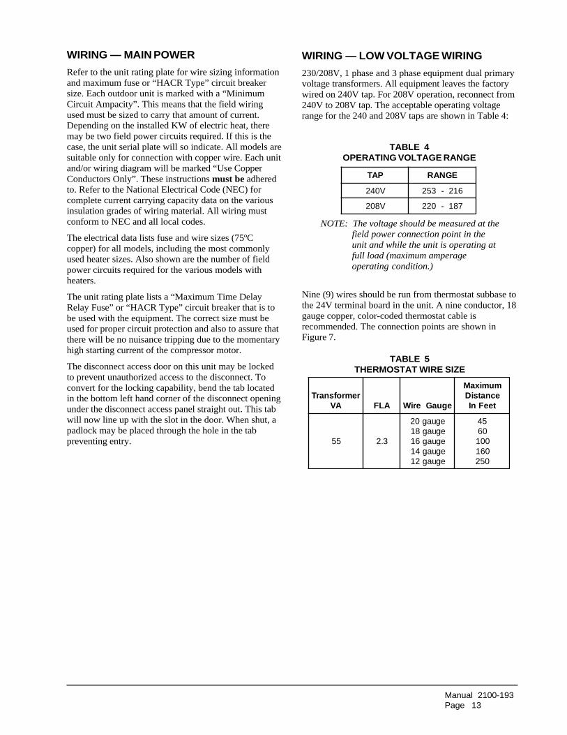
WIRING — MAIN POWER
Refer to the unit rating plate for wire sizing informationand maximum fuse or “HACR Type” circuit breakersize. Each outdoor unit is marked with a “MinimumCircuit Ampacity”. This means that the field wiringused must be sized to carry that amount of current.Depending on the installed KW of electric heat, theremay be two field power circuits required. If this is thecase, the unit serial plate will so indicate. All models aresuitable only for connection with copper wire. Each unitand/or wiring diagram will be marked “Use CopperConductors Only”. These instructions must be adheredto. Refer to the National Electrical Code (NEC) forcomplete current carrying capacity data on the variousinsulation grades of wiring material. All wiring mustconform to NEC and all local codes.
The electrical data lists fuse and wire sizes (75ºCcopper) for all models, including the most commonlyused heater sizes. Also shown are the number of fieldpower circuits required for the various models withheaters.
The unit rating plate lists a “Maximum Time DelayRelay Fuse” or “HACR Type” circuit breaker that is tobe used with the equipment. The correct size must beused for proper circuit protection and also to assure thatthere will be no nuisance tripping due to the momentaryhigh starting current of the compressor motor.
The disconnect access door on this unit may be lockedto prevent unauthorized access to the disconnect. Toconvert for the locking capability, bend the tab locatedin the bottom left hand corner of the disconnect openingunder the disconnect access panel straight out. This tabwill now line up with the slot in the door. When shut, apadlock may be placed through the hole in the tabpreventing entry.
Nine (9) wires should be run from thermostat subbase tothe 24V terminal board in the unit. A nine conductor, 18gauge copper, color-coded thermostat cable isrecommended. The connection points are shown inFigure 7.
TABLE 4OPERATING VOLTAGE RANGE
NOTE: The voltage should be measured at thefield power connection point in theunit and while the unit is operating atfull load (maximum amperageoperating condition.)
PAT EGNAR
V042 612-352
V802 781-022
TABLE 5THERMOSTAT WIRE SIZE
remrofsnarTAV ALF eguaGeriW
mumixaMecnatsiDteeFnI
55 3.2
eguag02eguag81eguag61eguag41eguag21
5406001061052
WIRING — LOW VOLTAGE WIRING
230/208V, 1 phase and 3 phase equipment dual primaryvoltage transformers. All equipment leaves the factorywired on 240V tap. For 208V operation, reconnect from240V to 208V tap. The acceptable operating voltagerange for the 240 and 208V taps are shown in Table 4:

Manual 2100-193Page 14
FIGURE 10LOW VOLTAGE WIRING
Manual 2100-193Page 15
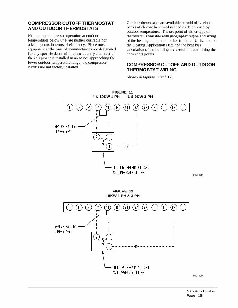
COMPRESSOR CUTOFF THERMOSTATAND OUTDOOR THERMOSTATS
Heat pump compressor operation at outdoortemperatures below 0° F are neither desirable noradvantageous in terms of efficiency. Since mostequipment at the time of manufacture is not designatedfor any specific destination of the country and most ofthe equipment is installed in areas not approaching thelower outdoor temperature range, the compressorcutoffs are not factory installed.
Outdoor thermostats are available to hold off variousbanks of electric heat until needed as determined byoutdoor temperature. The set point of either type ofthermostat is variable with geographic region and sizingof the heating equipment to the structure. Utilization ofthe Heating Application Data and the heat losscalculation of the building are useful in determining thecorrect set points.
COMPRESSOR CUTOFF AND OUTDOORTHERMOSTAT WIRING
Shown in Figures 11 and 12.
FIGURE 114 & 10KW 1-PH - - - 6 & 9KW 3-PH
FIGURE 1215KW 1-PH & 3-PH
MIS-409
MIS-409

Manual 2100-193Page 16
HEAT ANTICIPATION
The thermostats shown below have a fixed heatanticipator for stage 1 with no adjustment required.Stage 2 has an adjustable anticipator for the W2connection and fixed for the W3 connection. Both theW2 and W3 circuits are controlled by the stage 2 bulb.The only heat anticipator that needs to be checked is
stage 2 and it should be set to match the load carried bythe W2 circuit. The normal factory wiring provides foronly one electric heat contactor to be controlled by W2,and the anticipator should be set at .40A. If special fieldwiring is done, it is best to actually measure the load buta good rule is .40A for EACH heat contactor controlledby W2.
THERMOSTAT INDICATOR LAMPS
The red lamp marked "Em. Ht." comes on and stays onwhenever the system switch is placed in emergency heatposition. The green lamp marked "check" will come onif there is any problem that prevents the compressorfrom running when it is supposed to.
EMERGENCY HEAT POSITION
The operator of the equipment must manually place thesystem switch in this position. This is done when thereis a known problem with the unit, or when the green"check" lamp comes on indicating a problem.
COMPRESSOR MALFUNCTION LIGHT
Actuation of the green "check" lamp is accomplished bya relay output from the heat pump control board whichis factory installed. Any condition such as loss ofcharge, high head pressure, etc., that will preventcompressor from operating will cause green lamp toactivate. This is a signal to the operator of theequipment to place system in emergency heat position.
� No automatic changeover position - must manually place in heat or cool. Reversingvalve remains energized at all times system switch is in heat position (except duringdefrost cycle). No pressure equalization noise when thermostat is satisfied on eitherheating or cooling.
� Allows thermostat to control both heating and cooling operation when set in "Auto"position. Reversing valve de-energizes at end of each "On" heating cycle.
IMPORTANT NOTE: Both thermostat and subbase combinations shown aboveincorporate the following features: Man-Auto fan switch, Off-Heat-Cool-EM.Heat Switch, and two (2) indicator lamps - one for emergency heat and one forcompressor malfunction.
TABLE 6WALL THERMOSTAT and SUBBASE COMBINATIONS
puorG tatsomrehT esabbuS serutaeFetanimoderP
A 710-3048)9211R478T(
900-4048)1811L476Q(
looCrotaeH 1otuAoN
B 810-3048)4201N478T(
101-4048)1621F476Q(
looC�taeHcitamotuA 2noitisoPrevoegnahC
940-3048083-39F1
taehegats3,loocegats2elbammargorP cinortcelE
revoegnahclaunaMrootuA
240-3048)0701G1158T(
taehegats2,loocegats1revoegnahCcitamotuAcinortcelE
540-3048)1671A148T(
taehegats2,loocegats1launaM

Manual 2100-193Page 17
IMPORTANT INSTALLER NOTE
For improved start-up performance, wash the indoorcoil with a dishwashing detergent.
CRANKCASE HEATERS
All units are provided with some form of compressorcrankcase heat.
All single and three phase models have an insertionwell-type heater located in the lower section of thecompressor housing. This is a self-regulating typeheater that draws only enough power to maintain thecompressor at a safe temperature.
Some form of crankcase heat is essential to preventliquid refrigerant from migrating to the compressor,causing oil pump out on compressor start up andpossible valve failure due to compressing a liquid.
The decal in Figure 9 is affixed to all outdoor unitsdetailing start up procedure. This is very important.Please read carefully.
SERVICE HINTS
1. Caution homeowner to maintain clean air filters at alltimes. Also, not to needlessly close off supply andreturn air registers. This reduces air flow through thesystem which shortens equipment service life as wellas increasing operating costs.
2. Switching to heating cycle at 75°F or higher outsidetemperature may cause a nuisance trip of the remotereset high pressure switch. Turn thermostat off thenon to reset the high pressure switch.
3. The heat pump wall thermostats perform multiplefunctions. Be sure that all function switches arecorrectly set for the desired operating mode beforetrying to diagnose any reported service problems.
4. Check all power fuses or circuit breakers to be surethey are the correct rating.
5. Periodic cleaning of the outdoor coil to permit fulland unrestricted airflow circulation is essential.
SEQUENCE OF OPERATION
COOLING – Circuit R-Y makes at thermostat pullingin compressor contactor, starting the compressor andoutdoor motor. The G (indoor motor) circuit isautomatically completed on any call for coolingoperation or can be energized by manual fan switch onsubbase for constant air circulation.
START UP
HEATING – A 24V solenoid coil on reversing valvecontrols heating cycle operation. Two thermostatoptions, one allowing "Auto" changeover from cycle tocycle and the other constantly energizing solenoid coilduring heating season and thus eliminating pressureequalization noise except during defrost, are to be used.On "Auto" option, a circuit is completed from R-W1and R-Y on each heating "on" cycle, energizingreversing valve solenoid and pulling in compressorcontactor starting compressor and outdoor motor. R-Galso make starting indoor blower motor. Heat pumpheating cycle now in operation. The second option hasno "Auto" changeover position, but instead energizesthe reversing valve solenoid constantly whenever thesystem switch on subbase is placed in "Heat" position,the "B" terminal being constantly energized from R. Athermostat demand for heat completes R-Y circuitpulling in compressor contactor starting compressor andoutdoor motor.R-G make starting indoor blower motor.
FIGURE 13START UP LABEL
IMPORTANTThese procedures must be followedat initial start up and at any timepower has been removed for 12hours or longer.
To prevent compressor damage which mayresult from the presence of liquid refrigerant inthe compressor crankcase:
1. Make certain the room thermostat is in the"off" position (the compressor is not tooperate).
2. Apply power by closing the systemdisconnect switch. This energizes thecompressor heater which evaporates theliquid refrigerant in the crankcase.
3. Allow 4 hours or 60 minutes per poind ofrefrigerant in the system as noted on theunit rating plate, whichever is greater.
4. After properly elapsed time, the thermostatmay be set to operate the compressor.
5. Except as required for safety whileservicing. Do not open systemdisconnect switch.
7961-061

Manual 2100-193Page 18
PRESSURE SERVICE PORTSHigh and low pressure service ports are installed on allunits so that the system operating pressures can beobserved. Pressure tables can be found on Page 22covering all models. It is imperative to match the correctpressure table to the unit by model number.
DEFROST CYCLEThe defrost cycle is controlled by temperature and timeon the solid state heat pump control. See Figure 14.
When the outdoor temperature is in the lower 40° Ftemperature range or colder, the outdoor coiltemperature is 32° F or below. This coil temperature issensed by the coil sensor mounted near the bottom ofthe outdoor coil. Once coil temperature reaches 30° For below, the coil sends a signal to the control logic ofthe heat pump control and the defrost timer will start.
After 30 minutes at 30° F or below, the heat pumpcontrol will place the system in the defrost mode.
During the defrost mode, the refrigerant cycle switchesback to the cooling cycle, the outdoor motor stops,electric heaters are energized, and hot gas passingthrough the outdoor coil melts any accumulated frost.When the temperature rises to approximately 57° F, thecoil sensor will send a signal to the heat pump controlwhich will return the system to heating operationsautomatically.
If some abnormal or temporary condition such as a highwind causes the heat pump to have a prolonged defrostcycle, the heat pump control will restore the system toheating operation automatically after 10 minutes.
There are three settings on the heat pump control – 30minute, 60 minute, and 90 minute. Models are shippedwired on the 30 minute setting for greatest operating
economy. If special circumstances require a change toanother time, remove wire connected to terminal 30 andreconnect to desired terminal. Refer to Figure 10. Themanufucturer’s recommendation is for 3 minute defrostcycles.
There is a cycle speed up jumper on the control. Thiscan be used to reduce the time between defrost cycleoperation without waiting for time to elapse.
Use a small screwdriver or other metallic object, oranother 1/4 inch QC, to short between the SPEEDUPterminals to accedlerate the HPC timer and initiatedefrost.
Be careful not to touch any other terminals with theinstrument used to short the SPEEDUP terminals. Itmay take up to 10 seconds with the SPEEDUP terminalsshorted for the speedup to be completed and the defrostcycle to start.
As soon as the defrost cycle kicks in remove theshorting instrument from the SPEEDUP terminals.Otherwise the timing will remain accelerated and runthrough the 1 minute maximum defrost length sequencein a matter of seconds and will automatically terminatethe defrost sequence.
There is an initiate defrost jumper (sen jump) on thecontrol that can be used at any outdoor ambient duringthe heating cycle to simulate a 0° coil temperature.This can be used to check defrost operation of the unitwithout waiting for the outdoor ambient to fall into thedefrost region.
By placing a jumper across the SEN JMP terminals (a 1/4 inch QC terminal works best) the defrost sensormounted on the outdoor coil is shunted out and willactivate the timing circuit. This permits the defrostcycle to be checked out in warmer weather conditionswithout the outdoor temperature having to fall into thedefrost region.
In order to terminate the defrost testthe SEN JMP jumper must beremoved. If left in place too long thecompressor could stop due to the highpressure control opening because ofhigh pressure condition created byoperating in the cooling mode withoutdoor fan off. Pressure will risefairly fast as there is likely no actualfrost on the outdoor coil in thisartificial test condition.
There is also a 5 minute compressor timedelay function built into the HPC. Thisis to protect the compressor from shortcycling conditions. In some instances itis helpful to the service technician tooverride or speed up this timing period,and shorting out the SPEEDUP terminalsfor a few seconds can do this.
FIGURE 14DEFROST CONTROL BOARD
MIS-1528

Manual 2100-193Page 19
TROUBLESHOOTING
SOLID STATE HEAT PUMP CONTROLTROUBLESHOOTING PROCEDURE
1. Turn on AC power supply to indoor and outdoorunits.
2. Turn thermostat blower switch to "Fan On" – theindoor blower should start. (If it doesn't,troubleshoot indoor unit and correct problem).
3. Turn thermostat blower switch to "Auto" position.Indoor blower should stop.
4. Set system switch to heat or cool. Adjust thermostatto call for "Heat" or "Cool" – the indoor blower,compressor and outdoor fan should start.
NOTE: If there was no power to 24 volt transformer,the compressor and outdoor fan motor will notstart for 5 minutes. This is because of thecompressor short cycle protection.
motpmyS sesuaCelbissoP kcehCoTtahW riapeRrokcehCoTwoH
rotcatnocrosserpmoCezigrenetonseod
)gnitaehrognilooc(
gniriwtiucriclortnoC ,tinutanoitcennocRrofkcehC.C-RneewtebV42dna
rewopottinuroodtuootnoitcennocRnuR.lortnocpmuptaeh
tuokcolrosserpmoC .1 neewtebV42rofkcehCpmuptaehnoC-1L
.lortnoc
.1 nrutC-1LneewtebegatlovonfIteserotniaganodnaffotatsomreht
.hctiwserusserphgih
.2 hgihssorcakcehC.hctiwserusserp
.2 lliwdnaneposihctiwserusserphgihfI.hctiwserusserphgihecalper,teserton
elcyctrohsrosserpmoCnoitcetorp
C-CCneewtebV42rofkcehC.lortnocpmuptaehnoC-Ydna
deepsrepmujC-CCnwwtebegatlovonfIrewopsdnoces01nihtiwdnalanimretpu
evomeR.C-CCneewtebraeppadluohs.sdnoces01retfarepmujpudeeps
lortnocpmuptaeHevitcefed
elbissoprehtollakcehC.560-0012launaM.sesuac
.lortnocpmuptaehecalpeR
evitcefedrotcatnoC liocdetrohsroneporofkcehC.gnidniw
.rotcatnocecalpeR
rotomroodtuonaFnurtonseod
gnitaehrognilooc()tsorfedgnirudtpecxe
evitcefedrotoM detrohsroneporofkcehC.gnidniwrotom
.rotomecalpeR
.evitcefedroticapacrotoM kcehC.gnitarroticapackcehC.roticapacdetrohsroneporof
.roticapacecalpeR
lortnocpmuptaeHevitcefed
taehnoyalernafssorcakcehC)CN-moC(.lortnocpmup
.lortnocpmuptaehecalpeR
seodevlavgnisreveRezigreneton
)ylnognitaeh(
dionelosevlavgnisreveRevitcefedlioc
liocdetrohsroneporofkcehC .liocdionelosecalpeR
lortnocpmuptaeHevitcefed
C-VRneewtebV42rofkcehC.C-Bdna
.1
.2.gniriwtiucriclortnockcehC.lortnocpmuptaehecalpeR
otniogtonlliwtinUtsorfed
)ylnognitaeh(
rorosneserutarepmeTlortnocpmuptaeh
evitcefed
rosneserutarepmettcennocsiDssorcarepmujdnadraobmorf
.fed.tinidnaslanimretpudeepsesuacdluohssihT.slanimret
tsorfedahguorhtogottinueht.etunimenonihtiwelcyc
.1 ,elcyctsorfedhguorhtseogtinufI.rosneserutarepmetecalper
.2 ,elcyctsorfedhguorhtogtonseodtinufIlortnocpmuptaehecalper
tuoemoctonlliwtinUtsorfedfo
)ylnognitaeh(
rorosneserutarepmeTlortnocpmuptaeh
evitcefed
pudeepsssorcarepmuJesuacdluohssihT.slanimret
tsorfedfotuoemocottinueht.etunimenonihtiw
.1 ,elcyctsorfedfotuosemoctinufI.rosneserutarepmetecalper
.2 tsorfedfotuoemoctonseodtinufI.lortnocpmuptaehecalper,elcyc
TABLE 7TROUBLESHOOTING
Manual 2100-193Page 20
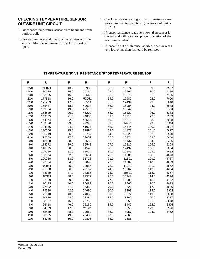
CHECKING TEMPERATURE SENSOROUTSIDE UNIT CIRCUIT
1. Disconnect temperature sensor from board and fromoutdoor coil.
2. Use an ohmmeter and measure the resistance of thesensor. Also use ohmmeter to check for short oropen.
3. Check resistance reading to chart of resistance usesensor ambient temperature. (Tolerance of part is± 10%.)
4. If sensor resistance reads very low, then sensor isshorted and will not allow proper operation of theheat pump control.
5. If sensor is out of tolerance, shorted, open or readsvery low ohms then it should be replaced.
TEMPERATURE "F" VS. RESISTANCE "R" OF TEMPERATURE SENSOR
F R F R F R F R
0.52-0.42-0.32-0.22-0.12-0.02-0.91-0.81-0.71-0.61-0.51-0.41-0.31-0.21-0.11-0.01-0.9-0.8-0.7-0.6-0.5-0.4-0.3-0.2-0.1-0.00.10.20.30.40.50.60.70.80.90.010.110.21
1786919900915853818137719821717845614099519254515539414734416759316594316050319126219802218018112724115750110107014753010620014607918939800199318817358996281210823677032570192707607705868146699346944265650654785
0.310.410.510.610.710.810.910.020.120.220.320.420.520.620.720.820.920.030.130.230.330.430.530.630.730.830.930.040.140.240.340.440.540.640.740.840.940.05
5896548255046351502541505820940957400264558444553459224770148989375783256733856384553545434753343623327130480368992751925538277572328622906238352696420304248332857220512216512989025340269891
0.350.250.350.450.550.650.750.850.950.060.160.260.360.460.560.660.760.860.960.070.170.270.370.470.570.670.770.870.970.080.180.280.380.480.580.680.780.88
47391768815738198971434714896174561221610175101351129414454177141028314743173131018212942138121388111951170311130112670110501742010000106796259992977092688356894480528750896876867
0.980.090.190.290.390.490.590.690.790.890.990.0010.1010.2010.3010.4010.5010.6010.7010.8010.9010.0110.1110.2110.3110.4110.5110.6110.7110.8110.9110.0210.1210.2210.3210.421
705743375617000704863866135638369326890616957285796507556445623580254905289437847674366426544644763447242814390460041293838375738763106362532543
Manual 2100-193Page 21
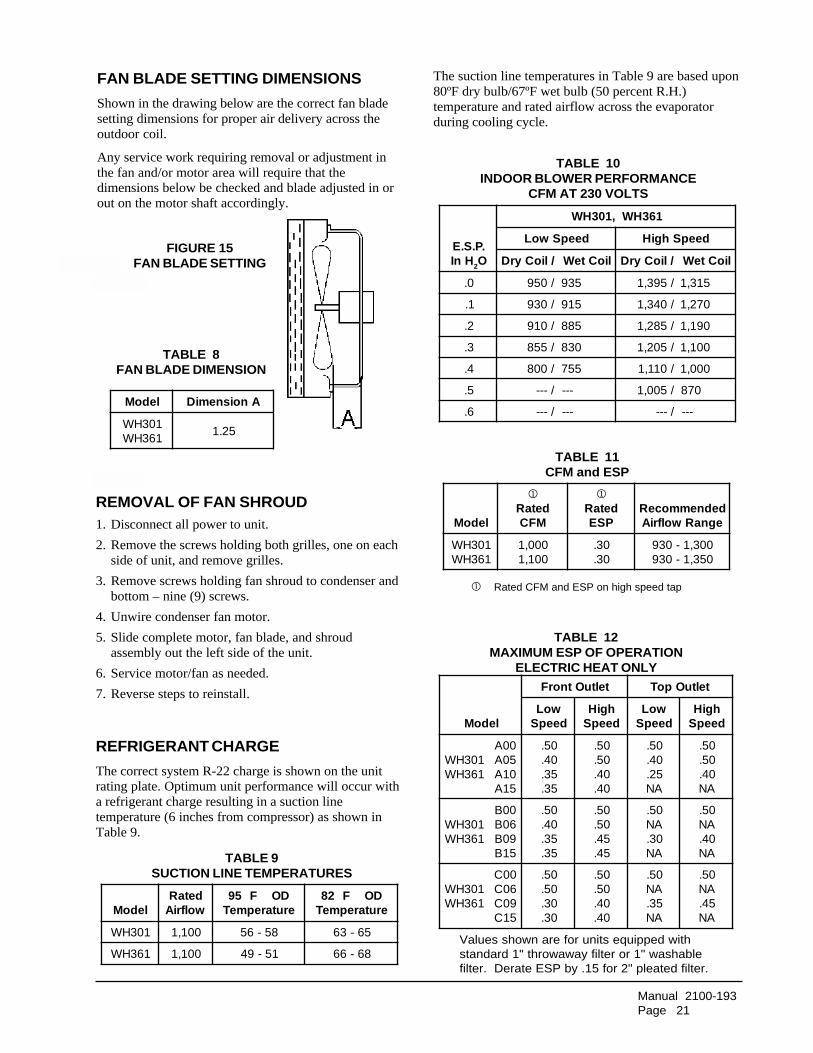
FAN BLADE SETTING DIMENSIONS
Shown in the drawing below are the correct fan bladesetting dimensions for proper air delivery across theoutdoor coil.
Any service work requiring removal or adjustment inthe fan and/or motor area will require that thedimensions below be checked and blade adjusted in orout on the motor shaft accordingly.
e Settin
REMOVAL OF FAN SHROUD1. Disconnect all power to unit.
2. Remove the screws holding both grilles, one on eachside of unit, and remove grilles.
3. Remove screws holding fan shroud to condenser andbottom – nine (9) screws.
4. Unwire condenser fan motor.
5. Slide complete motor, fan blade, and shroudassembly out the left side of the unit.
6. Service motor/fan as needed.
7. Reverse steps to reinstall.
REFRIGERANT CHARGE
The correct system R-22 charge is shown on the unitrating plate. Optimum unit performance will occur witha refrigerant charge resulting in a suction linetemperature (6 inches from compressor) as shown inTable 9.
The suction line temperatures in Table 9 are based upon80ºF dry bulb/67ºF wet bulb (50 percent R.H.)temperature and rated airflow across the evaporatorduring cooling cycle.
TABLE 10INDOOR BLOWER PERFORMANCE
CFM AT 230 VOLTS
.P.S.EHnI 2O
163HW,103HW
deepSwoL deepShgiH
/lioCyrD lioCteW /lioCyrD lioCteW
0. /059 539 /593,1 513,1
1. /039 519 /043,1 072,1
2. /019 588 /582,1 091,1
3. /558 038 /502,1 001,1
4. /008 557 /011,1 000,1
5. /--- --- /500,1 078
6. /--- --- /--- ---
TABLE 12MAXIMUM ESP OF OPERATION
ELECTRIC HEAT ONLY
ledoM
teltuOtnorF teltuOpoT
woLdeepS
hgiHdeepS
woLdeepS
hgiHdeepS
103HW163HW
00A50A01A51A
05.04.53.53.
05.05.04.04.
05.04.52.AN
05.05.04.AN
103HW163HW
00B60B90B51B
05.04.53.53.
05.05.54.54.
05.AN03.AN
05.AN04.AN
103HW163HW
00C60C90C51C
05.05.03.03.
05.05.04.04.
05.AN53.AN
05.AN54.AN
Values shown are for units equipped withstandard 1" throwaway filter or 1" washablefilter. Derate ESP by .15 for 2" pleated filter.
FIGURE 15FAN BLADE SETTING
TABLE 8FAN BLADE DIMENSION
ledoM AnoisnemiD
103HW163HW
52.1
TABLE 9SUCTION LINE TEMPERATURES
ledoMdetaRwolfriA
DOF59erutarepmeT
DOF28erutarepmeT
103HW 001,1 85-65 56-36
163HW 001,1 15-94 86-66
TABLE 11CFM and ESP
��Rated CFM and ESP on high speed tap
ledoM
�
detaRMFC
�
detaRPSE
dednemmoceRegnaRwolfriA
103HW163HW
000,1001,1
03.03.
003,1-039053,1-039

Manual 2100-193Page 22
Low side pressure ± 2 psig
High side pressure ± 5 psig
Tables are based upon rated CFM (airflow) across the evaporator coil andshould be found under section titled "Refrigerant Charge" on Page 21 inmanual. If there is any doubt as to correct charge being in the system, thecharge should be removed, system evacuated and recharged to serial plateinstructions.
TABLE 13COOLING PRESSURE (PSI) – OUTDOOR TEMPERATURE °F
ledoMriAnruteRerutarepmeT erusserP 57 08 58 09 59 001 501 011 511
103HW
BDged57BWged26
ediSwoLediShgiH
67532
87942
08362
18772
38192
48503
58913
78333
88743
BDged08BWged76
ediSwoLediShgiH
18142
38552
58962
78482
88892
09213
19723
39143
49653
BDged58BWged27
ediSwoLediShgiH
88052
09462
29972
39492
59803
79323
89833
001353
101863
163HW
BDged57BWged26
ediSwoLediShgiH
96012
17622
37242
57752
67372
87092
08603
28323
38933
BDged08BWged76
ediSwoLediShgiH
37612
67232
87842
08462
28182
48792
58413
78133
98843
BDged58BWged27
ediSwoLediShgiH
97322
18042
48652
68372
88092
09803
29523
49243
59063
Air Temperature Entering Outdoor Coil °F
TABLE 14HEATING PRESSURE (PSI) – OUTDOOR TEMPERATURE °F
Air Temperature Entering Outdoor Coil °F
ledoMriAnruteRerutarepmeT erusserP 0 5 01 51 02 52 03 53 04 54 05 55 06
103HW 07 o ediSwoLediShgiH
12341
52841
82351
23951
63561
93271
34081
74881
15791
55702
95712
36822
76932
163HW 07 o ediSwoLediShgiH
22541
52251
82951
13761
43771
83681
24791
64802
05022
55332
06642
56062
07572

Manual 2100-193Page 23
WH
301-
A
WH
301-
B
WH
301-
C
WH
361-
A
WH
361-
B
WH
361-
C
TABLE 15OPTIONAL ACCESSORIES
LEDOM NOITPIRCSED
50A-03HWHE segakcaPretaeH ➀ X
01A-03HWHE segakcaPretaeH ➀ X
50A-63HWHE segakcaPretaeH ➀ X
01A-63HWHE segakcaPretaeH ➀ X
51A-63HWHE segakcaPretaeH ➀ X
60B-30HWHE segakcaPretaeH ➀ X X
90B-30HWHE segakcaPretaeH ➀ X X
51B-30HWHE segakcaPretaeH ➀ X
60C-30HWHE segakcaPretaeH ➀ X X
90C-30HWHE segakcaPretaeH ➀ X X
51C-30HWHE segakcaPretaeH ➀ X X
3-POB etalPffOknalB X X X X X X
3-DAFB repmaDriAhserFcirtemoraB X X X X X X
3-DAFM repmaDriAhserFdezirotoM X X X X X X
3-VRC tsuahxEhtiwrotalitneVlaicremmoC X X X X X X
3-MFIE tsuahxEhtiwrezimonocE X X X X X X
A3A-VREW rotalitneVyrevoceRygrenE X X X X
A3C-VREW rotalitneVyrevoceRygrenE X X
3-HMC )CPL(lortnoCerusserPwoL X X X X X X
7-HMC )CAL(lortnoCtneibmAwoL X X X X
9-HMC CPL+CAL X X X X
41-HMC )TDO(tatsomrehTroodtuO X X
51-CMC )KS(tiKtratS X X
A50-BCMW tiKrekaerBtiucriC X
B30-BCMW tiKrekaerBtiucriC X X
10-DPMW tiKrekaerBtiucriC X X
A60-BCMW tiKrekaerBtiucriC X