Embed Size (px)
Citation preview

Wall mounted Fan Coil
Operation&Installation manual
◎ Before operating this product,please read the instruction
carefully and keep this manual for future use.

1.
3. Working principle
4. Specification
5. Installation
5.1 Location
5.2 Mounting plate installation
5.3 Installing the unit onto the mounting plate
5.4 Piping and drainage
5.5 Air purging
6. Remote controller operation
7. Functions & operation modes
8. Trouble shooting
8.1 Display
8.2 Failure Code
8.3 Causes&Action
9. Maintenance
10. Exploded view
11. Wiring diagram
Names of Components
2. Notice
1
2
2
3
4
5
5
5
6
7
8
10
11
14
14
14
15
16
17
CONTENT
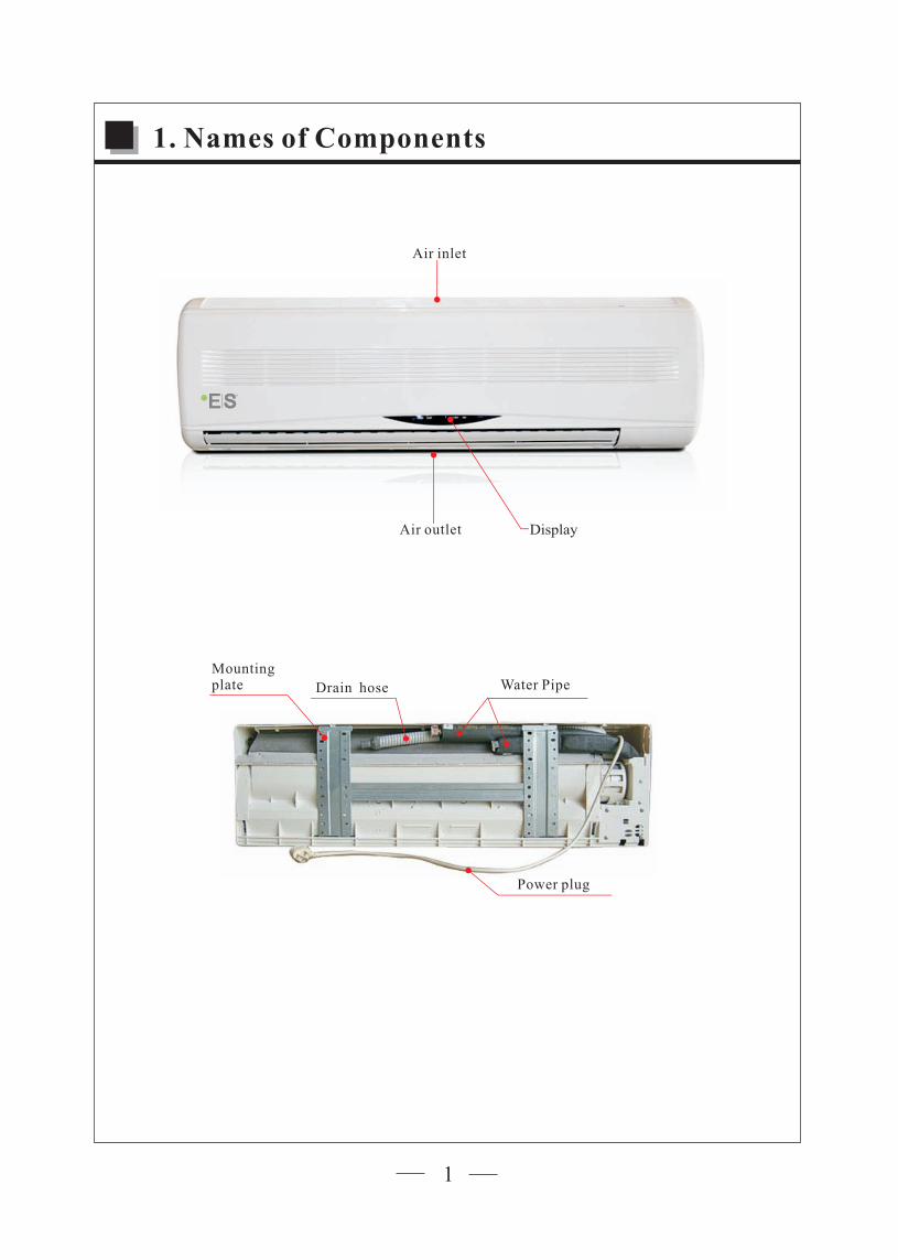
DisplayAir outlet
Air inlet
Water PipeDrain hose
Mounting plate
Power plug
1. Names of Components
1

● The unit is widely used together with central HVAC system in hotel, hospital, medicine
factory, theater, commercial building, office building, enterprises, chemical industry, exhibition
room, research institutes and so on.
● The installation, commissioning and maintenance of these machines should be performed by
qualified personnel having a good knowledge of standards and local regulations, as well as
experience of this type of equipment.
● Make sure that the rated voltage of the unit corresponds to that of the name plate before
commencing wiring work according to the wiring diagram.
● The unit must be GROUNDED to prevent possible hazard due to insulation failure.
● Make sure that the unit has been switched OFF before installing or servicing the unit.
● Keep the unit away from any combustible or corrosive environment.
● Disconnect the power plug when the fan coil is not going to be used for a long time.
Otherwise dirt may gather and cause low efficiency.
● Make sure the air inlets and outlets of the unit are not blocked.
2. Notice
Air inlet
Air outlet
Heat Exchanger
Fan Coil
The fan coil unit has no energy by itself but provides heating or cooling with hot or chilled water from
central water supply system(heat pump or chiller etc) .The fan of the unit blows through the heat
exchanger to cool or heat the air in the room.
If inlet water is cool, set the unit to cooling mode, the air outlet is cool air.
If inlet water is hot, set the unit to heating mode, the air outlet is hot air.
The unit is characterized with energy-saving, high efficiency, low noise, reliable and
convenient to select and install.
Fan
Central water supply system
3. Working principle
2

3. Specification
3
Model
Coil data
Tube diameterRows/fins
Fin height/length
Face area
mm
mm
W
m2
RPM
m3/h
W
dB(A)
mm
mm
mm
KgNet Weight
Packaging Dimension (L×D×H)
Net Dimension (L×D×H)
Drain Connection--(O.D)
Pipe Connector Size
Noise Level at high speed
Power Input
Power Supply
Air Flow at High Speed
Fan data
Motor data
Fan Speed
Power Output
L
M
H
1100 (cooling)1150 (heating)
15
1070×377×262
1020×315×210
16
G1/2
37
7235
35
G3/8
13
890×280×210
950×345×260
12
650 (cooling)750 (heating)
220~20/50,60Hz/1PH
1000
1100
1300
35
0.25
310×796
0.092
15
1150
1000
800
2R/17fin
7
FCW 18.1 FCW 12.1
31×561
Output Under Different Water Temperature
FCW 12.1 Fan Speed Working Mode Water Inlet Temp (℃ )
FCW 18.1 FCW 12.1
Capacity(W) Capacity(W) Capacity(W)
Water Flow Rate(L/S)/Water Pressure Drop(Kpa)
Low Speed
MediumSpeed
High Speed
Cooling
Heating
Cooling
Heating
Cooling
Heating
Note: (1) Capacity Test Condition for cooling: room temperature is DB/WB 27/19℃ .
Capacity Test Condition for heating: room temperature is DB/WB 20/-℃ .
(2) specifications are subject to change without prior notice. For actual pecifications of unit, please refer to the stickers on the unit.
The
5
7
9
6050
45
5
79
60
5045579
60
50
45 3100
3540
4490
11121365153031603660
4600
11201375
1545
3260
371046401130
1390
1670
0.062/30 0.076/40 0.13/40
2025
1785
151051604000
3440
2010
1730
1470
5020
3920
3340199016851460
4890
3870
3100
3660
3375
268573655775
4830
34553225
2530
7220
56254575342030352510
6710
5225
4390
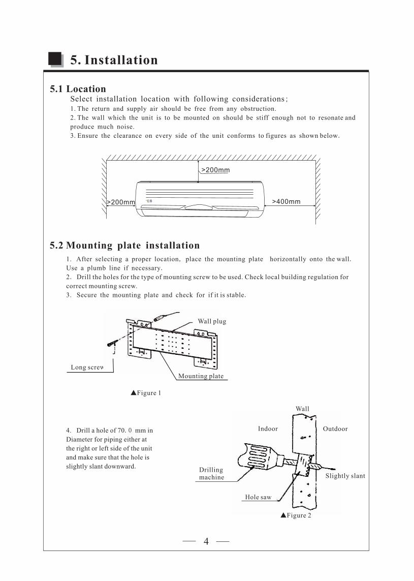
Select installation location with following considerations;1. The return and supply air should be free from any obstruction.
2. The wall which the unit is to be mounted on should be stiff enough not to resonate and
produce much noise.
3. Ensure the clearance on every side of the unit conforms to figures as shown below.
5.1 Location
>200mm
>200mm >400mm
5.2 Mounting plate installation
5. Installation
1. After selecting a proper location, place the mounting plate horizontally onto the wall.
Use a plumb line if necessary.
2. Drill the holes for the type of mounting screw to be used. Check local building regulation for
correct mounting screw.
3. Secure the mounting plate and check for if it is stable.
Mounting plate
▲Figure 1
Long screw
Indoor
Slightly slant
Outdoor
Drillingmachine
Hole saw
Wall
Indoor
▲Figure 2
4. Drill a hole of 70.0 mm in
Diameter for piping either at
the right or left side of the unit
and make sure that the hole is
slightly slant downward.
4
Wall plug
stationarity
Wall
Cut with saw
Cap
Wall sleeve pipe
Drill from the outside
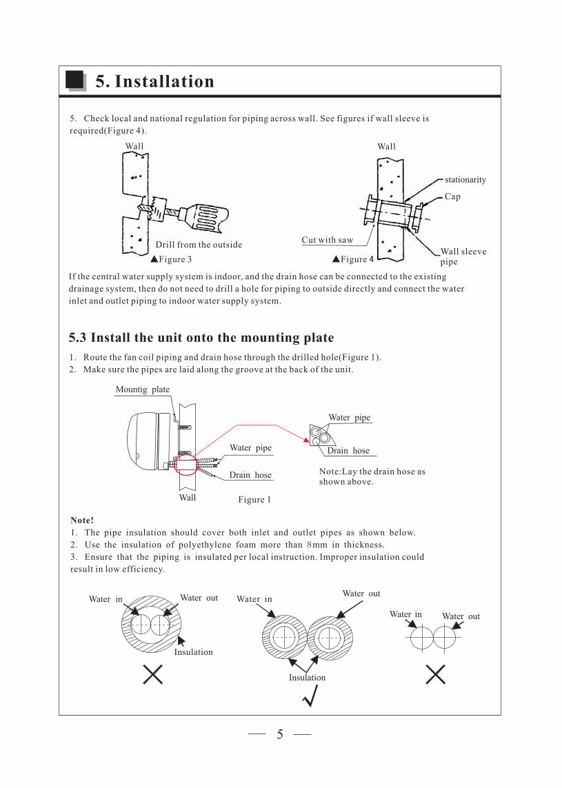
If the central water supply system is indoor, and the drain hose can be connected to the existing
drainage system, then do not need to drill a hole for piping to outside directly and connect the water
inlet and outlet piping to indoor water supply system.
▲Figure 3 ▲Figure 4
5. Installation
5. Check local and national regulation for piping across wall. See figures if wall sleeve is
required(Figure 4).
5.3 Install the unit onto the mounting plate
Drain hose
Water pipe
Mountig plate
Wall
Water pipe
Drain hose
Note:Lay the drain hose as shown above.
Figure 1
1. Route the fan coil piping and drain hose through the drilled hole(Figure 1).
2. Make sure the pipes are laid along the groove at the back of the unit.
Note!
1. The pipe insulation should cover both inlet and outlet pipes as shown below.
2. Use the insulation of polyethylene foam more than 8mm in thickness.
3. Ensure that the piping is insulated per local instruction. Improper insulation could
result in low efficiency.
Wall
Water in Water out
Insulation
Water in Water out
Insulation
Water in Water out
5

Wall
push
A B
C D
1
3
2
4
Indoor Outdoor
Note: Any part of drainpipe should not be higher than the unit.Connect to the
water supply system
Piping fixture
Figure 2Figure 3
Figure 4
5.4 Piping and drainage
5. Installation
3. Mount the upper of fan coil (part 1 and 2)onto the two notches (A and B)on the mounting
plate(Figure 2).
4. Push the bottom of the fan coil (part 3 and 4)towards the wall (Figure 3)in order to engage
the locking clips (part C and D)
1. Fix the drain hose on the wall by a piping fixture (Figure 4).
2. Connect the water inlet and outlet piping to a water supply system, and make sure the seals
are fitted neatly.
6

1. Lift up the filter cover, there are four latches in the front
cover. Don't pull it hard in case the latches will be snapped.
2. There are two grooves in each frame grille. pull up and take off the air filter.
Figure 1
After connecting the water piping and drainpipe, and fixing the fan coil onto mounting plate,take the
following steps for air purging;
Figure 2
5.5 Air purging
5. Installation
7

3. Find the as the picture, unscrew the valve by hand or long nose pliers.purging valve
4. Open the water inlet valve to run the water flow into the coil, and check the water in a transparent
pipe connected with the valve. If the transparent pipe is filled with water without any bubbles, the air
is completely purged from the coil. Then close the purging valve.
Figure 3Figure 4
Transparent pipe
5. Installation
8

6. Remote controller operation
9
1
23
45
6
7 8
9
1011
1312
Introduction of function buttons on the remote controller
NO. FUNCTION PART
1
2
3
4
5
6
7
8
9
10
11
12
13
Display
Power ON/OFF
Temp
Mode
Timer OFF
T ONimer
Fan
Hour and minute
Vertical louvers stepping
Horizontal louvers
Sleep
Clock
Reset
To switch the unit on and off.
To set the desired ambient temperature.
To select Auto / Cool / / Fan / Heat operationDehumidity
To set timer OFF
To set timer ON
To select fan speed:Auto/Low/Medium//High
To set clock and time setting
Used to set air flow vertical direction
Reserved function
Key to set/cancel the Sleep mode regardless of the operating mode of the unit.
Key is used to set the current time.
To reset all settings

7. Functions & operation modes
10
When unit is turned on,press “ ” to choose working mode.It comes in the sequence:
Mode selection1
Dehumidity modeAuto mode
Cooling mode
Heating mode
Fan mode
1)
2)
3)Indoor fan speed and blower louvers can be set by remote controller.The fan motor will run in low speed
under Sleep function.
Once cooling or heating mode is fixed, the RUN lamp continuously lights.
Initial temperature setting is 24℃,increase or decrease 1℃ by pressing ▲ or▼each time to set target temp.
The temperature setting range is
2)Push the button to select the FAN mode of AUTO, LOW, MED, or HIGH.
3)Ai flow direction can be set to swing or stay at a fixed angle.
℃~ ℃. ℃1) 16 31 The initial temperature setting is 21 .
Auto mode2
Cool Operation3
1.When the dehumidifying mode is selected, the setting temp. is defaulted at 25℃ and can not be adjusted.
The setting fan speed also can' t be adjusted and fan will works in low fan speed. Fan direction can be
adjusted.
2. The timer function is enabled when the dehumidifying model is operating. The sleep function is disabled.
The fan will works in low fan speed and can not be adjusted.
Dehumidity mode4
By pressing the FAN key several times it is possible to adjust the fan speed between the three available
speeds,or to activate the AUTO mode. The operating mode appears on the display:
Fan mode5
NOTE1)If the AUTO mode is not comfortable for you, the desired mode can be selected manually.
2)Air flow direction can be set to swing or stay at a fixed angle.
Auto
Low
Medium speed
High speed
Once enter the mode, RUN lamp flickers.
The unit will logically choose the heating or cooling mode by sensing the difference between
the actual ambient room temperature and the set temperature on the remote controller.

7. Functions & operation modes
11
Temp. Setting7After operation mode is selected, press or ▲ button to set the temperature.
▲ Button: Every time the button is pressed, temperature setting increases 1°C.
▼ Button: Every time the button is pressed, temperature setting decreases 1°C.
▼
Mode
Set temperature rangeDefault
Auto
16 31℃~ ℃
24℃
Cooling
16 31℃~ ℃
21℃
Dry
25℃
Fan
—
——Heating
16 31℃~ ℃
27℃
Timer mode setting 8
Use the buttons and to set the timer programming in order to switch on and off the unit at
the desired time.
[How to set Timer ON]
The button can be used to set the timer programming as
wished in order to switch on the appliance at your desired time.
1) Press button, then you can press the ''HR'' and''MIN''
buttons to select your desired time for unit on.
- Time setting changes by 1 hour at each time you press the
''HR'' button.
- Time setting changes by 1 minute at each time you press the
''MIN'' button.
2) Press button again to confirm the timer on setting.
3) Once ON Timer is set, timing starts, and the unit turns off. When the set time is up,unit turns on and Timer
is cleared.
The button can be used to set the timer function as wished in order
to switch off the appliance at your desired time.
1) Press button, then you can press the ''HR and MIN
buttons to select your desired time for unit off.
- Time setting changes by 1 hour at each time you press the
''HR'' button.
- Time setting changes by 1 minute at each time you press the
''MIN'' button.
2) Press button again to confirm the timer off setting.
3) When OFF Timer is set, before the time is up, the unit keeps on
working normally.When the set time is up, unit stops working immediately regardless of the ambient temp..
'' '' ''
[How to set Timer OFF]
℃~ ℃. ℃
When the heating mode is selected, the fan may not start up straight away because the
ANTI-COOLING mode is present.
1)The temperature setting range is 16 31 The initial temperature setting is 27 .
2)
Heating mode6

7. Functions & operation modes
12
Sleep mode setting 9
Sleep mode can be set in cooling, heating or auto operation mode.
In sleep mode,
- Fan speed is automatically set at low speed.
- Press the " " button to set the unit to the sleep mode.
The indicator will light up on the display. In this mode,
the temperature increases/decrease in cooling/heating mode
operation by 1°C every two hours of working. After reaching 3°C,
the unit maintains this temperature through to the eighth hour (8 hours)
of operation in the "sleep" mode and then switches off automatically.
Ts = Set temperature
Sleep function in cooling mode
Ts = Set temperature
Hour
Hour
Sleep OffSleep On
0 2 4 68
Ts+3Ts+2
Ts+1
Temp. Sleep On
0 2 4 68
Ts-3
Ts-2Ts-1
Temp.
Sleep function in heating modeSleep Off
(High)
Setting the fan 10
By pressing the button several times it is possible to adjust the
fan speed between the three available speeds, or to activate the AUTO
speed. The operating speed appears on the display:
(Auto) (Low) (Medium)
Vertical louvers11
To change airflow direction vertically, press button, the signal
lamp is ON in the display.
Each time the button is pressed, airflow direction changes in the
sequence as follows:
Memory function12
The unit has memory function as default.

8.2 Failure Code
Code Solution
Change the sensor
IndicatorMeaningNO.
If more than one failures happens at the same time, warning will be shown by the
power light alternatively. For instance, if Room Temp. Sensor and Coil Temp. Sensor failures
happen at the same time, the power light will flicker twice in first eight seconds and then
three times in another eight seconds.
Coil temperature sensor failure
Room temperature sensor failure
Fan motor failure
8. Trouble shooting
1
2
3
E2
E3
E7
Running light blinks twice in every 8 seconds
Change the sensor
Change the sensor
Running light blinks three times in every 8 seconds
Running light blinks seven times in every 8 seconds
13
The POWER light is on after unit is powered on. When the unit is operating the RUN light is on.(The light
blinks in auto mode and is on after operation mode is selected).In SLEEP or TIMER mode, the two digit
No. displays room temp. and corresponding indication light is on.Current setting temperature is displayed
when adjusting setting temperature.
Data(temperature\ time\ failure code)
8.1 Display
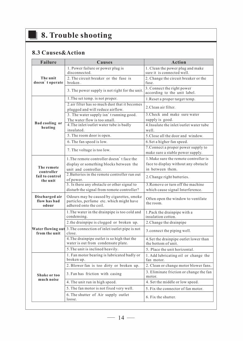
8.3 Causes&Action
8. Trouble shooting
5.The unit is inclined heavily.
Water flowing out from the unit
1.The water in the drainpipe is too cold and condensing.
2.the drainpipe is clogged or broken up.
3.The connection of inlet/outlet pipe is not close.
4.The drainpipe outlet is so high that the water is out from condensate plate.
1.Pack the drainpipe with a insulation cotton.
4.Set the drainpipe outlet lower than the bottom of unit.
2.Change the drainpipe
3.connect the piping well.
5.Place the unit horizontal.
6. The shutter of Air supply outlet loose.
6. Fix the shutter.
1. Fan motor bearing is lubricated badly or broken up.
2. Blower fan is too dirty or broken up.
3. Fan has friction with casing
4. The unit run in high speed.
5. The fan motor is not fixed very well.
1. Add lubricating oil or change the fan motor.
2. Clean or change motor blower fans.
3. Eliminate friction or change the fan motor.
4. Set the middle or low speed.
5. Fix the connector of fan motor.
Discharged air flow has bad
odour
Odours may be caused by cigarettes, smoke particles, perfume etc. which might have adhered onto the coil.
Often open the window to ventilate the room.
Shake or too much noise
The unit doesn' t operate
Bad cooling or heating
1. Power failure or power plug is disconnected.
2. The circuit breaker or the fuse is broken .
3. The power supply is not right for the unit.
1. Clean the power plug and make sure it is connected well.
2. Change the circuit breaker or the fuse.
3. Connect the right power according to the unit label.
1.The set temp. is not proper.
2.air filter has so much dust that it becomes
plugged and will reduce airflow.
3.The water supply isn' t running good.
The water flow is too .small4.The inlet/outlet water tube is badly
insulated.
5. The room door is open.
6. The fan speed is low.
7. The voltage is too low.
1.Reset a proper target temp.
2.Clean air filter.
3.Check and make sure water
supply is good.
4.Insulate the inlet/outlet water tube
well.
5.Close all the door and window.
6.Set a higher fan speed.
7.Connect a proper power supply to
make sure a stable power supply.
The remote controller
fail to control the unit
3. Is there any obstacle or other signal to
disturb the signal from remote controller?
3.Remove or turn off the machine
which cause signal Interference.
1.The remote controller doesn' t face the
display or something blocks between the
unit and controller.
2.Batteries in the remote controller run out
of power.
1.Make sure the remote controller is
face to display without any obstacle
in between them.
2.Change right batteries.
Failure Causes Action
14
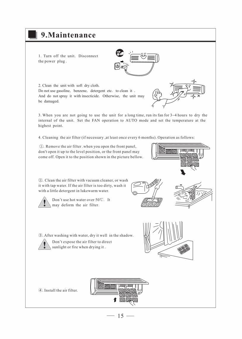
1.
the power plug
Turn off the unit. Disconnect
.
2. Clean the unit
Do not use gasoline, benzene, detergent etc. to clean it .
And do not spray it with insecticide. Otherwise, the unit may
be damaged.
with soft dry cloth.
3. When you are not going to use the
internal of the unit. Set the FAN operation to AUTO mode and set the temperature at the
highest point.
unit for a long time, run its fan for 3~4 hours to dry the
4. Cleaning the air filter (if necessary ,at least once every 6 months). Operation as follows:
9.Maintenance
①.Remove the air filter .when you open the front panel,
don't open it up to the level position, or the front panel may
come off. Open it to the position shown in the picture bellow.
②.
it with tap water.
with a little detergent in lukewarm water.
Clean the air filter with vacuum cleaner, or wash
If the air filter is too dirty, wash it
Don’t use hot water over 50℃. It
may deform the air filter.
③. After washing with water, dry it well in the shadow.
Don’t expose the air filter to direct
sunlight or fire when drying it .
④. Install the air filter.
15

1
3
4
5
6
7
Item Description Model no.
10. Exploded view
16
Article no.
Remote controllerFCW 12.1FCW 18.1 R8060804520
Room and pipe sensor R8060900210
Step motorFCW 18.1
EvaporatorFCW 12.1
FCW 18.1
2
FCW 18.1
R140204139
R140204140
Fan motorFCW 12.1
FCW 18.1
R8061802290
R8061802570
8 Controller and display boardFCW 12.1
FCW 18.1
R8060805530
R8060805540
Transformer
FCW 12.1 R8061900030
Fan motor capacitorFCW 12.1 R8060200457
R8060200082
FCW 12.1FCW 18.1
R8061600320
FCW 12.1FCW 18.1
R8061900040

CN-
DISP
11V
AC-L
AC-N
EVAPORATORHARDWARE
FAN MOTOR
CN-FAN
WIRING DIAGRAM
SMFM
ROOM TEMP SENSOR
COIL SENSORCN-SMDCNFK
~
STEP MOTOR
11.Wiring diagram
17

R120400386,V1.0
April 2014,