Embed Size (px)
Citation preview
6/28/2012
11:5
0:2
0
AM
RE
VISIO
N
C:\
d\projects\standards\structures\2013book\06110-1of6.d
gn
NO.
SHEET
NO.
INDEX
rd960rh
DESCRIPTION:
REVISION
LAST
2013
FDOT DESIGN STANDARDS
Open Joints
2" Cover @
and Precast or C-I-P Coping
Begin or End Retaining Wall
3" to maintain minimum cover (Typ.)
Field cut reinforcing as required
3 sp.@ 6"
3"
Slab is skewed)
when Junction
(Required only
(Top of Slab)
4 ~ Bars 5F
Bars 5B1 Coping
Expansion Joints
2" Cover @
Gutter Line
this sheet and Detail "A")
"Expansion Joint Detail"
Expansion Joint (See
Sides (Typ.)
2" Cover
" Open Joint�
" V-Groove Spacingb
in Precast Coping
" Open Joint�
Transfer Devices
1" Ø Dowel LoadJunction Slab
Top of
or fiber cap
Approved metal
Joint Filler
1’-0"1’-0"
Junction Slab
Bottom of
for details)
Devices (See Typical Sections
1" Ø Dowel Load Transfer
� Expansion
" Preformed Expansion�
"�
" open joints in Traffic Railing)�with
(Junction Slab expansion joints are to coincide
CROSS REFERENCE: For Detail "A", see Sheet 2.
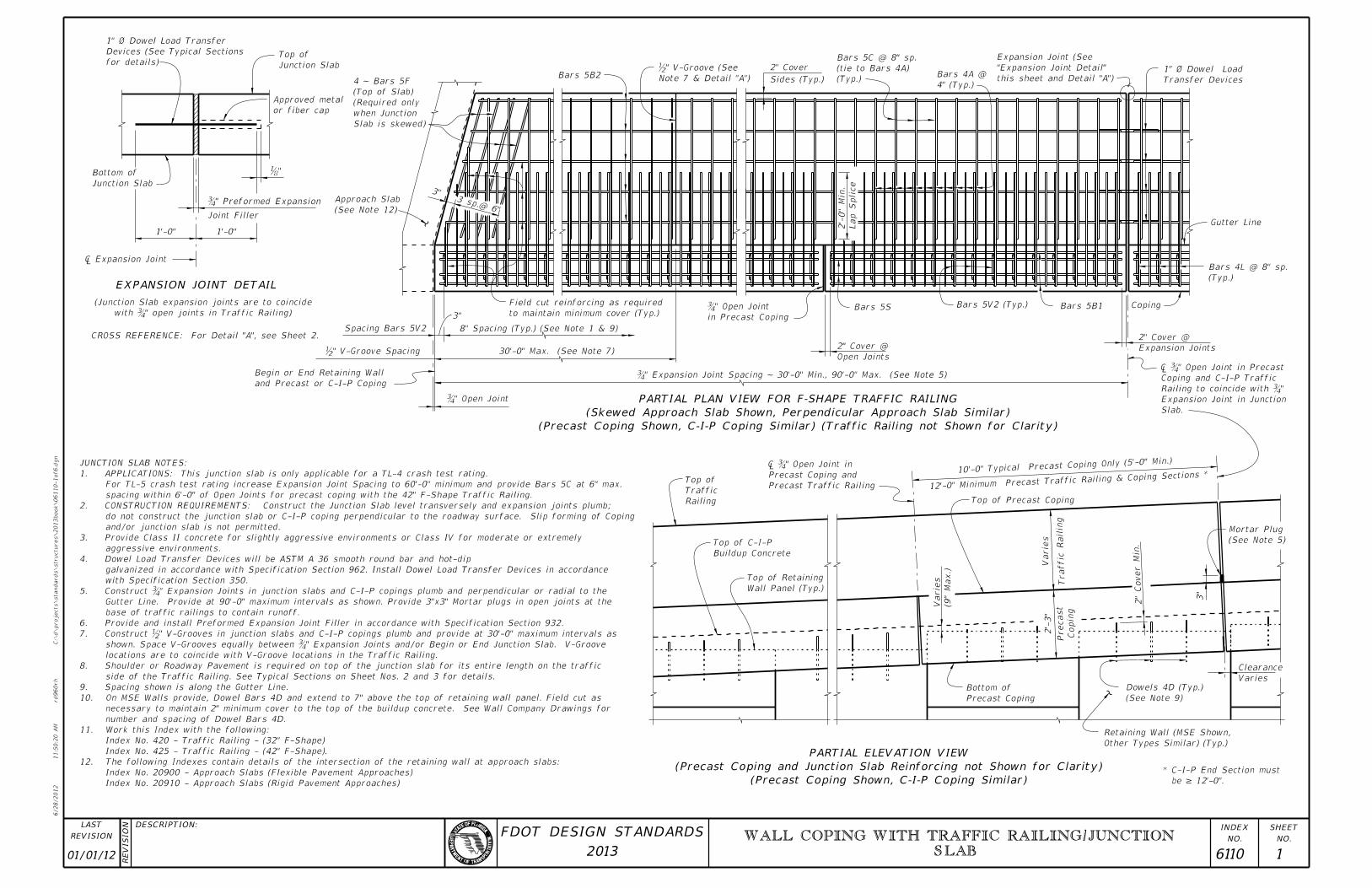
EXPANSION JOINT DETAIL
Bars 5B2
Bars 5V2 (Typ.)
(Typ.)
(tie to Bars 4A)
Bars 5C @ 8" sp.
4" (Typ.)
Bars 4A @
Bars 5S
Lap S
plice
2’-
0"
Min.
30’-0" Max. (See Note 7)
Note 7 & Detail "A")
b" V-Groove (See
˘�" Expansion Joint Spacing ~ 30’-0" Min., 90’-0" Max. (See Not
(See Note 12)
Approach Slab
Spacing Bars 5V2 8" Spacing (Typ.) (See Note 1 & 9)
(Typ.)
Bars 4L @ 8" sp.
(See Note 9)
Dowels 4D (Typ.)
Varies
Clearance
2"
Cover
Min.
Varie
s
Copin
g
Precast
Precast Coping
Bottom of
Wall Panel (Typ.)
Top of Retaining
Top of Precast Coping
(9"
Max.)
Varie
s
10’-0" Typical Precast Coping Only
(5’-0" Min.)
Traffic Railin
g
Other Types Similar) (Typ.)
Retaining Wall (MSE Shown,
Precast Traffic Railing
Precast Coping and
â�� ˘�" Open Jo
Railing
Traffic
Top of
3"
(See Note 5)
Mortar Plug
12’-0" Minimum Precast Traffic Railing & Copin
g Sections *
2’-
3"
Slab.
Expansion Joint in Junction
"�Railing to coincide with
Coping and C-I-P Traffic
" Open Joint in Precast��»
(Precast Coping Shown, C-I-P Coping Similar) (Traffic Railing not Shown for Clarity)
(Skewed Approach Slab Shown, Perpendicular Approach Slab Similar)
PARTIAL PLAN VIEW FOR F-SHAPE TRAFFIC RAILING
Index No. 20910 - Approach Slabs (Rigid Pavement Approaches)
Index No. 20900 - Approach Slabs (Flexible Pavement Approaches)
12. The following Indexes contain details of the intersection of the retaining wall at approach slabs:
Index No. 425 - Traffic Railing - (42" F-Shape).
Index No. 420 - Traffic Railing - (32" F-Shape)
11. Work this Index with the following:
number and spacing of Dowel Bars 4D.
necessary to maintain 2" minimum cover to the top of the buildup concrete. See Wall Company Drawings for
10. On MSE Walls provide, Dowel Bars 4D and extend to 7" above the top of retaining wall panel. Field cut as
9. Spacing shown is along the Gutter Line.
side of the Traffic Railing. See Typical Sections on Sheet Nos. 2 and 3 for details.
8. Shoulder or Roadway Pavement is required on top of the junction slab for its entire length on the traffic
locations are to coincide with V-Groove locations in the Traffic Railing.
 shown. Space V-Grooves equally between ˘�" Expansion Joints and/or Begin or End Junction Slab. V-Gr
7. Construct b" V-Grooves in junction slabs and C-I-P copings plumb and provide at 30’-0" maximum intervals as
6. Provide and install Preformed Expansion Joint Filler in accordance with Specification Section 932.
base of traffic railings to contain runoff.
Gutter Line. Provide at 90’-0" maximum intervals as shown. Provide 3"x3" Mortar plugs in open joints at the
5. Construct ˘�" Expansion Joints in junction slabs and C-I-P copings plumb and perpendicular or radial to
with Specification Section 350.
galvanized in accordance with Specification Section 962. Install Dowel Load Transfer Devices in accordance
4. Dowel Load Transfer Devices will be ASTM A 36 smooth round bar and hot-dip
aggressive environments.
3. Provide Class II concrete for slightly aggressive environments or Class IV for moderate or extremely
and/or junction slab is not permitted.
do not construct the junction slab or C-I-P coping perpendicular to the roadway surface. Slip forming of Coping
2. CONSTRUCTION REQUIREMENTS: Construct the Junction Slab level transversely and expansion joints plumb;
spacing within 6’-0" of Open Joints for precast coping with the 42" F-Shape Traffic Railing.
For TL-5 crash test rating increase Expansion Joint Spacing to 60’-0" minimum and provide Bars 5C at 6" max.
1. APPLICATIONS: This junction slab is only applicable for a TL-4 crash test rating.
JUNCTION SLAB NOTES:
Buildup Concrete
Top of C-I-P
(Precast Coping Shown, C-I-P Coping Similar)
(Precast Coping and Junction Slab Reinforcing not Shown for Clarity)
PARTIAL ELEVATION VIEW
be = 12’-0".
* C-I-P End Section must
01/01/12 6110 1
WALL COPING WITH TRAFFIC RAILING/JUNCTION
SLAB
6/28/2012
11:5
0:2
3
AM
RE
VISIO
N
C:\
d\projects\standards\structures\2013book\06110-2of6.d
gn
NO.
SHEET
NO.
INDEX
rd960rh
DESCRIPTION:
REVISION
LAST
2013
FDOT DESIGN STANDARDS
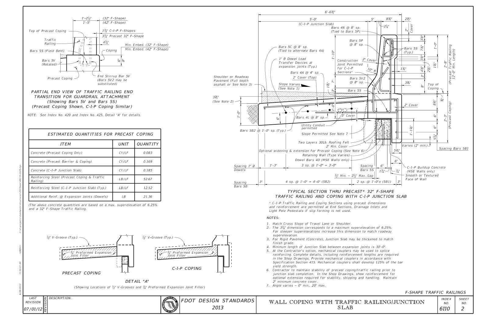
Min. Embed. (42" F-Shape)
Min. Embed. (32" F-Shape)
Coping
(42" F-Shape)
(32" F-Shape)
8"
6"
Precast Coping
(Rotated)
Bars 5V
Bars 5S (Field Bent)
Top of Precast Coping
NOTE: See Index No. 420 and Index No. 425, Detail "A" for details.
LB
52.67
" Preformed Expansion Joint Filler)�" V-Grooves and b(Showing Locations of
" V-Groove (Typ.)b " V-Groove (Typ.)b
"�4
1’-5"
"b1’-2
F-SHAPE TRAFFIC RAILINGS
DETAIL "A"
PRECAST COPING
ITEM
ESTIMATED QUANTITIES FOR PRECAST COPING
UNIT QUANTITY
8"
3"
10" R
7"
1’-
10"
@ 8" sp.
Bars 5V2
Bars 5S
2" Cover
2"
Bars 4A @ 4" sp.
"4
3
5"
"2
13
"2
14
"4
12
"2
13
"212
"216’-6
Cover
(Typ.)
Bars 5S
@ 8" sp.
Bars 5P
"4
31
1’-
0"
Bars 4L @ 8" sp.
expansion joints (Typ.)
Transfer Devices at
1" Ø Dowel Load
(Tied to alternate Bars 4A)
Bars 5C @ 8" sp.
2’-
8"
2" Cover (Top)
"438
"411
"433
5’-0"
Spacing Bars 5B1
6"

1’-
0"
"4
11
2" Cover
(See Note 1)
Slope Variesasphalt or See Note 3)
Pavement (Full depth
Shoulder or Roadway
12’-
0"
Min.
Length)
(Precast Traffic Railin
g
3"
(C-I-P Junction Slab)
(Precast Copin
g)
(Tied to Bars 5P)
Bars 4N @ 8" sp.
"4
17
�»ï»¿
3" Cover
Concrete (Precast Coping Only)
Concrete (Precast Barrier & Coping)
0.185
12.52
21.36
0.169
0.083
1’-
0"
Railing
Traffic
3˘�" Precast 32" F-S
Bars 5B2 @ 1’-0" sp. (Typ.)
b" Min. ~ 2b" Max. Gap
6"
Joint Filler˘�" Preformed Expan
Joint Filler˘�" Preformed Expan
CY/LF
CY/LF
substituted)
(Bars 5V2 may be
End Stirrup Bar 5V
1˘�" C-I-P F-Sh
Railing)
Reinforcing Steel (Precast Coping & TrafficLB/LF
and a 32" F-Shape Traffic Railing.
(The above concrete quantities are based on a max. superelevation of 6.25%
6"
3"
Retaining Wall (Type Varies)
Optional widening & extension for Precast Coping (See Note 6)
Bars 5S
Spacing
"4
11’-
1
Coping
Top of
(See Note 2)
"433
3 sp. @ 1’-0" = 3’-0"
Dowels
Spacing 1" Ø 1’-3"
Bars 5B
Spacing 4 sp. @ 1’-0" = 4’-0" (5B2)Face of Wall
Smooth or Textured
2 sp. @ 1’-0"– (5B1) 3"
"415
2’-
3"
6"
"2
18
Two Layers 30Lb. Roofing Felt

2" Min. Cover
6"
Varies (2" min.)
Dowel Bars 4D (MSE Walls only)
Slope Permitted See Note 7
Sections*
for C-I-P
Joint Permitted
Construction
permittedUtility Conduit
TRAFFIC RAILING AND COPING WITH C-I-P JUNCTION SLAB
TYPICAL SECTION THRU PRECAST* 32" F-SHAPE
NOTES:
7. Angle varies ~ 0° min., 20° max.
2" minimum concrete cover.
optional extension required for stability, shipping and handling. Maintain
junction slab completion. In the Shop Drawings, show reinforcement for
6. Contractor to maintain stability of precast coping/traffic railing prior to
yield strength.
Specification Section 415. Mechanical couplers shall develop 125% of the bar
in the Shop Drawings. Provide mechanical couplers in accordance with
reinforcing. Complete details, including reinforcement lengths are required
5. At the Contractor’s option, mechanical couplers may be used to splice
4. Minimum length of Junction Slab between expansion joints is 30’-0".
finish grade.
3. For Rigid Pavement (Concrete), Junction Slab may be thickened to match
superelevation.
For steeper superelevations increase this dimension to match roadway
2. The 3˘�" dimension corresponds to a maximum superelevation of 6.
1. Match Cross Slope of Travel Lane or Shoulder.
(Precast Coping Shown, C-I-P Coping Similar)
(Showing Bars 5V and Bars 5S)
TRANSITION FOR GUARDRAIL ATTACHMENT
PARTIAL END VIEW OF TRAFFIC RAILING END
(MSE Walls only)
C-I-P Buildup ConcreteConcrete (C-I-P Junction Slab)
Reinforcing Steel (C-I-P Junction Slab) (Typ.)
C-I-P COPING
CY/LF
LB/LF
Light Pole Pedestals if slip forming is not used.
and reinforcement are permitted at End Sections, Drainage Inlets and
* C-I-P Traffic Railing and Coping Sections using precast dimensions
Additional Reinf. @ Expansion Joints (Dowels)
07/01/12 6110 2
WALL COPING WITH TRAFFIC RAILING/JUNCTION
SLAB
6/28/2012
11:5
0:2
6
AM
RE
VISIO
N
C:\
d\projects\standards\structures\2013book\06110-3of6.d
gn
NO.
SHEET
NO.
INDEX
rd960rh
DESCRIPTION:
REVISION
LAST
2013
FDOT DESIGN STANDARDS
10"
45°
9"
1’-2" (3
2"
F)
54°30’
1’-
1b"
"215
3"
5F
5C
2’-0"
2’-0"
N/A
2’-0"
5
5
5F
C
A
1" Ø Dowel
BAR 4A
1" Ø DOWEL
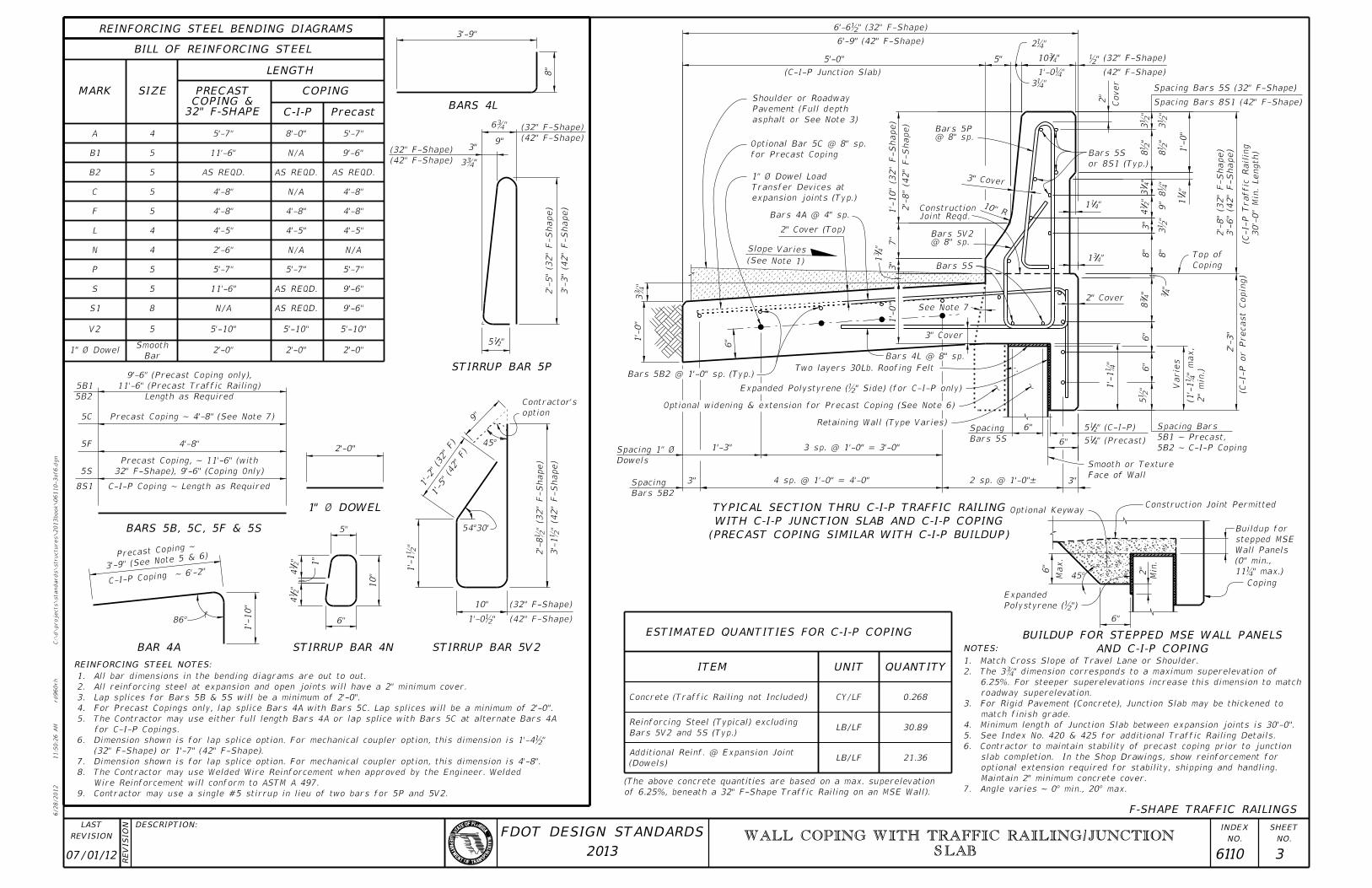
REINFORCING STEEL BENDING DIAGRAMS
option
Contractor’s
10"
"2
14
"2
14
1"
STIRRUP BAR 4N
6"
6"
"4
38
Bars 5S
"4
3
"411
1’-
0"
2"
expansion joints (Typ.)
Transfer Devices at
1" Ø Dowel Load
10" R
7"
3"
"431
3" Cover
5"
Bars 4A @ 4" sp.
b"
3b"
8b"
5’-0"
@ 8" sp.Bars 5P
2’-
3"
@ 8" sp.Bars 5V2
1’-
0"
"4
31
C-I-P Coping ~
6’-2"
STIRRUP BAR 5V2
3’-9"
8"
BARS 4L
86°
6"

1’-
10"
BARS 5B, 5C, 5F & 5S
4’-8"
Precast Coping ~ 4’-8" (See Note 7)
5S
C-I-P Coping ~ Length as Required
32" F-SHAPECOPING &PRECAST
8’-0"5’-7"4
4’-8"
4’-8" 4’-8"
L
P
N
S
V2
4 4’-5"
5 5’-7"
4 N/A
5 11’-6" AS REQD.
5’-7"
5 5’-10" 5’-10"
"4
13
"2
14
3"
"4
11
2" Cover
2" Cover (Top)
(See Note 1)
Slope Varies
Bars 4L @ 8" sp.
for Precast Coping
Optional Bar 5C @ 8" sp.
asphalt or See Note 3)
Pavement (Full depth
Shoulder or Roadway
5"
6"
5’-7"
4’-8"
4’-5"
5’-7"
N/A
5’-10"
2’-0"
PrecastC-I-P
COPING
4’-8"
9’-6"
2’-6"
Bar
Smooth
B1
30’-
0"
Min.
Length)
(C-I-P Traffic Railin
g(C-I-P or Precast Copin
g)
Joint Reqd.Construction
Cover
(C-I-P Junction Slab)
3’-9" (See Note 5
& 6)Precast
Coping ~
STIRRUP BAR 5P
SIZEMARK
LENGTH
BILL OF REINFORCING STEEL
REINFORCING STEEL NOTES:
32" F-Shape), 9’-6" (Coping Only)
Precast Coping, ~ 11’-6" (with
4’-5"
3" Cover
QUANTITYUNIT
ESTIMATED QUANTITIES FOR C-I-P COPING
ITEM
21.36
30.89
1’-
0"
B2 5 AS REQD. AS REQD. AS REQD.
11’-6" N/A 9’-6"
5B1
5B2 Length as Required
11’-6" (Precast Traffic Railing)
9’-6" (Precast Coping only), Bars 5B2 @ 1’-0" sp. (Typ.)
5B2 ~ C-I-P Coping
5B1 ~ Precast,
Spacing Bars
6"
AS REQD. 9’-6"
8S1
9"
"�6
(42" F-Shape)
(32" F-Shape)
(42" F-Shape)
(32" F-Shape)
2’-
5" (3
2"
F-S
hape)
3’-
3" (4
2"
F-S
hape)
1’-5" (4
2"
F)
2’-
8b" (3
2"
F-S
hape)
3’-
1b" (4
2"
F-S
hape)
1’-0b"
(32" F-Shape)
(42" F-Shape)
Concrete (Traffic Railing not Included)
1’-
10" (3
2"
F-S
hape)
2’-
8" (4
2"
F-S
hape)
6’-6b" (32" F-Shape)
6’-9" (42" F-Shape) 

"4310
1’-
(32" F-Shape)
(42" F-Shape)
Spacing Bars 5S (32" F-Shape)
Spacing Bars 8S1 (42" F-Shape)

9"
3b"
3’-
6" (4
2"
F-S
hape)
2’-
8" (3
2"
F-S
hape)
S1 8 N/A
or 8S1 (Typ.)
Bars 5S 8b"
3b"
8"
8"
6"
0.268
LB/LF
LB/LF
CY/LF
Bars 5V2 and 5S (Typ.)
Reinforcing Steel (Typical) excluding
3 sp. @ 1’-0" = 3’-0"
Bars 5S
Spacing
6"
45°
6"
Coping
Construction Joint Permitted
Min.
2"
Polystyrene (b")
Expanded
Coping
Top of
4 sp. @ 1’-0" = 4’-0"3"
Dowels
Spacing 1" Ø
Bars 5B2
Spacing
1’-3"
2 sp. @ 1’-0"– 3"
F-SHAPE TRAFFIC RAILINGS
Face of Wall
Smooth or Texture
Two layers 30Lb. Roofing Felt

1’-
5b"
" (Precast)415
" (C-I-P)215
(PRECAST COPING SIMILAR WITH C-I-P BUILDUP)
WITH C-I-P JUNCTION SLAB AND C-I-P COPING
TYPICAL SECTION THRU C-I-P TRAFFIC RAILING
of 6.25%, beneath a 32" F-Shape Traffic Railing on an MSE Wall).
(The above concrete quantities are based on a max. superelevation
Varie
s
See Note 7
NOTES:
7. Angle varies ~ 0° min., 20° max.
Maintain 2" minimum concrete cover.
optional extension required for stability, shipping and handling.
slab completion. In the Shop Drawings, show reinforcement for
6. Contractor to maintain stability of precast coping prior to junction
5. See Index No. 420 & 425 for additional Traffic Railing Details.
4. Minimum length of Junction Slab between expansion joints is 30’-0".
match finish grade.
3. For Rigid Pavement (Concrete), Junction Slab may be thickened to
roadway superelevation.
6.25%. For steeper superelevations increase this dimension to match
2. The 3˘�" dimension corresponds to a maximum superelevatio
1. Match Cross Slope of Travel Lane or Shoulder.
Max.
AND C-I-P COPING
BUILDUP FOR STEPPED MSE WALL PANELS
11˘�" m
(0" min.,
Wall Panels
stepped MSE
Buildup for
2"
min.)
(
1’-1̆
�"
Optional Keyway
Retaining Wall (Type Varies)
Optional widening & extension for Precast Coping (See Note 6)
Expanded Polystyrene (b" Side) (for C-I-P only)
9. Contractor may use a single #5 stirrup in lieu of two bars for 5P and 5V2.
Wire Reinforcement will conform to ASTM A 497.
8. The Contractor may use Welded Wire Reinforcement when approved by the Engineer. Welded
7. Dimension shown is for lap splice option. For mechanical coupler option, this dimension is 4’-8".
(32" F-Shape) or 1’-7" (42" F-Shape).
6. Dimension shown is for lap splice option. For mechanical coupler option, this dimension is 1’-4b"
for C-I-P Copings.
5. The Contractor may use either full length Bars 4A or lap splice with Bars 5C at alternate Bars 4A
4. For Precast Copings only, lap splice Bars 4A with Bars 5C. Lap splices will be a minimum of 2’-0".
3. Lap splices for Bars 5B & 5S will be a minimum of 2’-0".
2. All reinforcing steel at expansion and open joints will have a 2" minimum cover.
1. All bar dimensions in the bending diagrams are out to out.
(Dowels)
Additional Reinf. @ Expansion Joint
07/01/12 6110 3
WALL COPING WITH TRAFFIC RAILING/JUNCTION
SLAB
6/28/2012
11:5
0:2
9
AM
RE
VISIO
N
C:\
d\projects\standards\structures\2013book\06110-4of6.d
gn
NO.
SHEET
NO.
INDEX
rd960rh
DESCRIPTION:
REVISION
LAST
2013
FDOT DESIGN STANDARDS
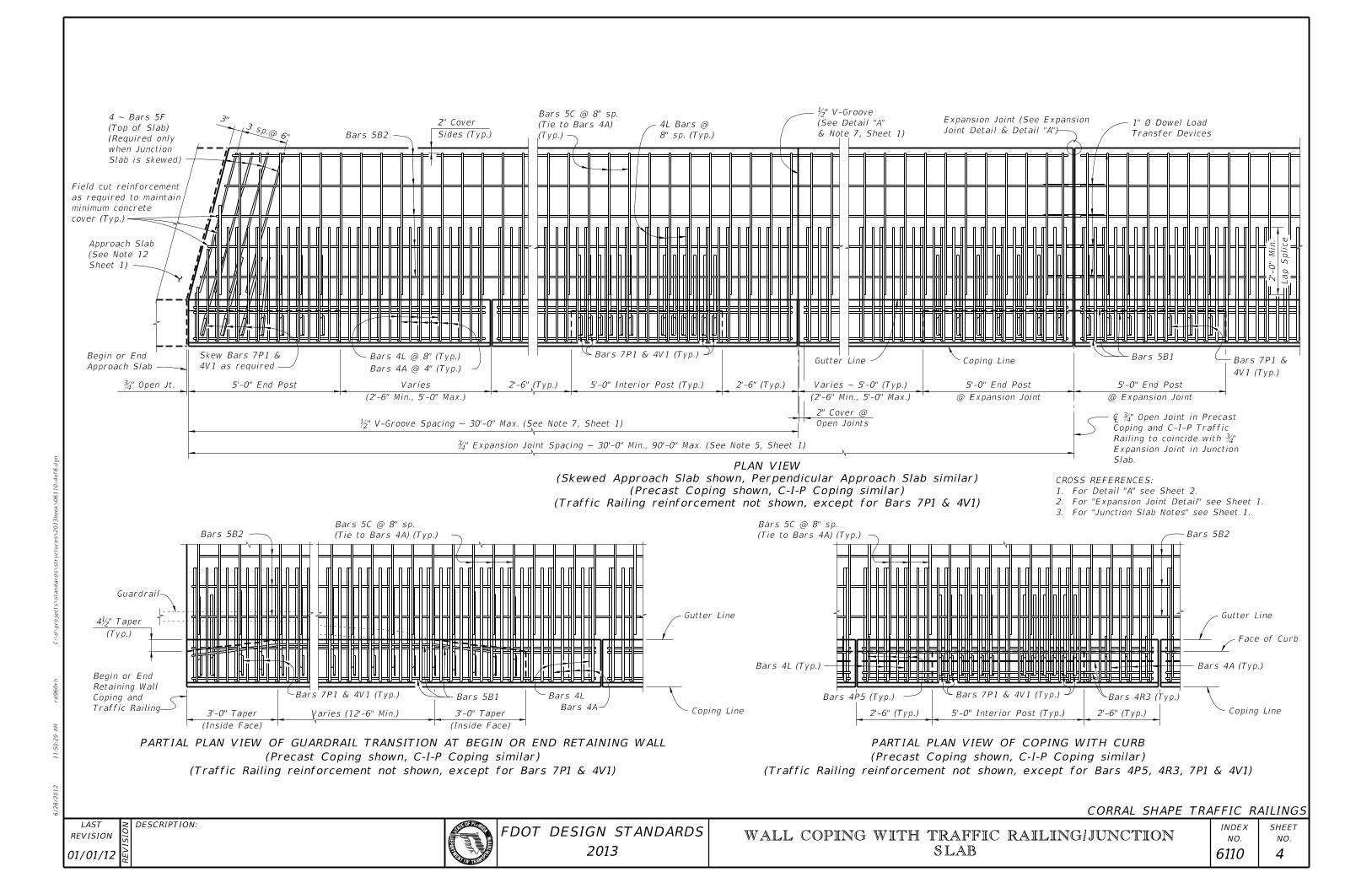
Coping Line
Bars 4A (Typ.)
Face of Curb
Gutter Line
Bars 4R3 (Typ.)
2’-6" (Typ.)
Bars 7P1 & 4V1 (Typ.)
5’-0" Interior Post (Typ.)2’-6" (Typ.)
Bars 4P5 (Typ.)
Bars 5B2
3. For "Junction Slab Notes" see Sheet 1.
2. For "Expansion Joint Detail" see Sheet 1.
1. For Detail "A" see Sheet 2.
CROSS REFERENCES:
Coping Line
Gutter Line
Bars 5B2
Guardrail
Traffic Railing
Coping and
Retaining Wall
Begin or End
(Inside Face)
3’-0" Taper Varies (12’-6" Min.)
Bars 7P1 & 4V1 (Typ.)
(Inside Face)
3’-0" Taper
Bars 5B1 Bars 4L
Bars 4A
Joint Detail & Detail "A")
Expansion Joint (See Expansion
Sides (Typ.)
2" Cover
Bars 5B2
3 sp.@ 6"
3"
Slab is skewed)
when Junction
(Required only
(Top of Slab)
4 ~ Bars 5F
cover (Typ.)
minimum concrete
as required to maintain
Field cut reinforcement
Approach Slab
Begin or End
5’-0" End Post
4V1 as required
Skew Bars 7P1 &
(2’-6" Min., 5’-0" Max.)
Varies 2’-6" (Typ.)
Bars 7P1 & 4V1 (Typ.)
5’-0" Interior Post (Typ.) 2’-6" (Typ.)
(2’-6" Min., 5’-0" Max.)
Varies ~ 5’-0" (Typ.)
Open Joints
2" Cover @
Gutter Line
@ Expansion Joint
5’-0" End Post
Coping Line
@ Expansion Joint
5’-0" End Post
Bars 5B1
4V1 (Typ.)
Bars 7P1 &
" Open Jt.�
(Typ.)
" Taperb4
CORRAL SHAPE TRAFFIC RAILINGS
Bars 4A @ 4" (Typ.)
Bars 4L @ 8" (Typ.)
Lap S
plice
2’-
0"
Min.
˘�" Expansion Joint Spacing ~ 30’-0" Min., 90’-0" Max. (See Note 5, Shee
b" V-Groove Spacing ~ 30’-0" Max. (See Note 7, Sheet 1)
(Typ.)
(Tie to Bars 4A)
Bars 5C @ 8" sp.
& Note 7, Sheet 1)
(See Detail "A"
b" V-Groove
(Tie to Bars 4A) (Typ.)
Bars 5C @ 8" sp.
Bars 4L (Typ.)
(Tie to Bars 4A) (Typ.)
Bars 5C @ 8" sp.
8" sp. (Typ.)
4L Bars @
Sheet 1)
(See Note 12
Approach Slab
Transfer Devices
1" Ø Dowel Load
Slab.
Expansion Joint in Junction
"�Railing to coincide with
Coping and C-I-P Traffic
" Open Joint in Precast��»
(Traffic Railing reinforcement not shown, except for Bars 7P1 & 4V1)
(Precast Coping shown, C-I-P Coping similar)
(Skewed Approach Slab shown, Perpendicular Approach Slab similar)
PLAN VIEW
(Traffic Railing reinforcement not shown, except for Bars 4P5, 4R3, 7P1 & 4V1)
(Precast Coping shown, C-I-P Coping similar)
PARTIAL PLAN VIEW OF COPING WITH CURB
(Traffic Railing reinforcement not shown, except for Bars 7P1 & 4V1)
(Precast Coping shown, C-I-P Coping similar)
PARTIAL PLAN VIEW OF GUARDRAIL TRANSITION AT BEGIN OR END RETAINING WALL
01/01/12 6110 4
WALL COPING WITH TRAFFIC RAILING/JUNCTION
SLAB
6/28/2012
11:5
0:3
2
AM
RE
VISIO
N
C:\
d\projects\standards\structures\2013book\06110-5of6.d
gn
NO.
SHEET
NO.
INDEX
rd960rh
DESCRIPTION:
REVISION
LAST
2013
FDOT DESIGN STANDARDS
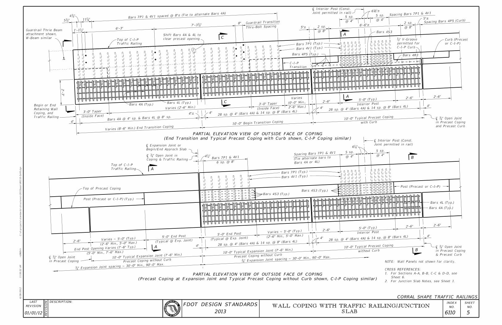
4"
2’-6"2’-6"
Interior Post
5’-0" (Typ.)
without Curb10’-0" Typical Pre
cast Coping
Post (Precast or C-I-P)
@ 4"
5 sp.
@ 4"
5 sp.Spacing Bars 7P1
& 4V1
Bars 4V1 (Typ.)
Bars 7P1 (Typ.)
Bars 4S3 (Typ.)
Bars 4S3 (Typ.)
6 sp. @ 8"
Bars 7P1 & 4V1
Traffic Railing
Top of C-I-P
Top of Precast Coping
Post (Precast or C-I-P) (Typ.)
2’-6"
(2’-6" Min., 5’-0" Max.)
Varies ~ 5’-0" (Typ.)
(5’-0" Min., 7’-6" Max.)
End Post Opening Varies (7’-6" Typ
.)
Precast Coping without Curb
10’-0" Typical Expansion Joint (7’-
6" Min.)
(Typical @ Exp. Joint)
5’-0" End Post
4"
(Typical @ Exp. Joint)
5’-0" End Post
Precast Coping without Curb
10’-0" Typical Expansion Joint (7’-
6" Min.)
(2’-6" Min., 5’-0" Max.)
Varies ~ 5’-0" (Typ.)
4"
2’-6"
& Precast Curb
in Precast Coping
" Open Joint��»
Joint permitted in rail)
� Interior Post (C
"�6Begin/End Approch Slab
� Expansion Joi
Coping & Traffic Railing
" Open Joint in��»
in Precast Coping
" Open Joint��»
4"
2’-6"2’-6"
Bars 4R3
or C-I-P)
Curb (Precast
Spacing Bars 4P5 (Curb)
5"–
@ 8"
2 sp.
Spacing Bars 7P1 & 4V1
@ 4"
5 sp.
6’-6"–
@ 4"
5 sp.
"–416
@ 8"
2 sp.5"–
Bars 4V1 (Typ.)
Bars 7P1 (Typ.)
Bars 4P5 (Typ.)
Transition
C-I-P
Thru-Bolt Spacing
Guardrail Transition
8"
6’-3"
Traffic Railing
Top of C-I-P
Traffic Railing
Coping, and
Retaining Wall
Begin or End
(Inside Face)
3’-0" Taper
4"
Varies (8’-6" Min.) End Transition
Coping
Varies (2’-6" Min.)
4"– 4"
10’-0" Begin Transition Coping
(Inside Face)
3’-0" Taper
2’-6" Max.)
(0’-0" Min.,
Varies
4"
2’-6"
with Curb10’-0" Typical Pre
cast Coping
Interior Post
5’-0" (Typ.)
and Precast Curb
in Precast Coping
" Open Joint��»
Joint permitted in rail)
� Interior Post (C
"�7’-3
"�11
"�4
"�5
"b1’-1
(Precast Coping at Expansion Joint and Typical Precast Coping without Curb shown, C-I-P Coping similar)
PARTIAL ELEVATION VIEW OF OUTSIDE FACE OF COPING
BA
A
B
(End Transition and Typical Precast Coping with Curb shown, C-I-P Coping similar)
PARTIAL ELEVATION VIEW OF OUTSIDE FACE OF COPING
C
A
AC
CORRAL SHAPE TRAFFIC RAILINGS
Bars 4A (Typ.)Bars 4L (Typ.)
Bars 7P1 & 4V1 spaced @ 8"– (Tie to alternate
Bars 4A)
Bars 4A @ 4" sp. & Bars 4L @ 8" sp.
28 sp. @ 4" (Bars 4A) & 14 sp. @ 8"
(Bars 4L)28 sp. @ 4" (Bars
4A) & 14 sp. @ 8" (Bars 4L)
4b"
28 sp. @ 4" (Bars 4A) & 14 sp. @ 8"
(Bars 4L)28 sp. @ 4" (Bars
4A) & 14 sp. @ 8" (Bars 4L)
Bars 4L (Typ.)
Bars 4A (Typ.)
2. For Junction Slab Notes, see Sheet 1.
Sheet 6.
1. For Sections A-A, B-B, C-C & D-D, see
CROSS REFERENCES:
NOTE: Wall Panels not shown for clarity.
ï »¿̆�" Expansion Joint spacing ~ 30
’-0" Min., 90’-0"
ï »¿̆�" Expansion Joint spacing ~ 30
’-0" Min., 90’-0"
Bars 4A or 4L)(Tie alternate bar
s to
W-Beam similar
attachment shown,
Guardrail Thrie Beam
clear precast opening
Shift Bars 4A & 4L toBars 4S3
2’-
3"
C-I-P Curb
permitted for
b" V-Groove
01/01/12 6110 5
WALL COPING WITH TRAFFIC RAILING/JUNCTION
SLAB
6/28/2012
11:5
0:3
4
AM
RE
VISIO
N
C:\
d\projects\standards\structures\2013book\06110-6of6.d
gn
NO.
SHEET
NO.
INDEX
rd960rh
DESCRIPTION:
REVISION
LAST
2013
FDOT DESIGN STANDARDS
Min.
2"
(Type A)
Silicone Sealant
Low Modulus
Top of Curb
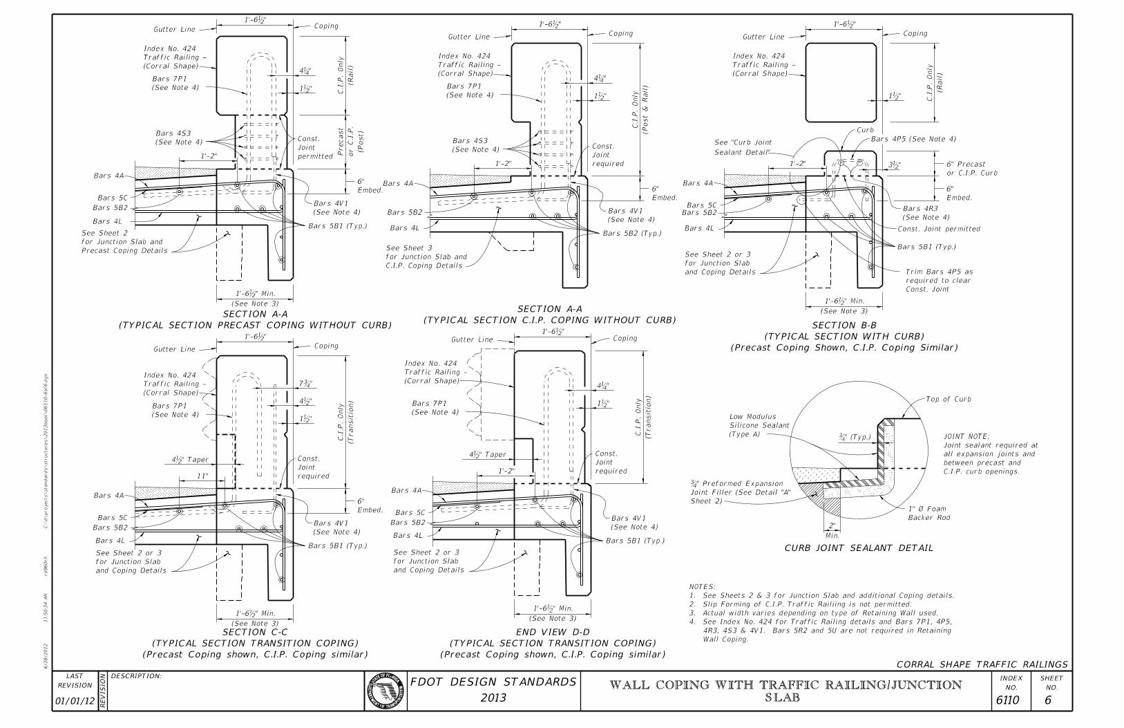
C.I.P. curb openings.
between precast and
all expansion joints and
Joint sealant required at
JOINT NOTE:
Backer Rod
1" Ø Foam
Sheet 2)
Joint Filler (See Detail "A"
" Preformed Expansion�
and Coping Details
for Junction Slab
See Sheet 2 or 3
Const. Joint
required to clear
Trim Bars 4P5 as
Const. Joint permitted
(See Note 4)
Bars 4R3
Embed.
6"
or C.I.P. Curb
6" Precast
Bars 4P5 (See Note 4)
Curb
Sealant Detail"
See "Curb Joint
1’-2"
(Rail)
C.I.P.
Only
CopingGutter Line
(Corral Shape)
Traffic Railing -
Index No. 424
(See Note 3)
1’-6b" Min.
"b3
"b1
1’-6b"
Gutter Line
(Corral Shape)
Traffic Railing -
Index No. 424
Coping
(Post
& Rail)
C.I.P.
Only(See Note 4)
Bars 7P1
(See Note 4)
Bars 4S3
1’-2" required
Joint
Const.
Embed.
6"
(See Note 4)
Bars 4V1
Bars 5B2 (Typ.)
C.I.P. Coping Details
for Junction Slab and
See Sheet 3
"b1
"�4
1’-6b"
Gutter Line
(Corral Shape)
Traffic Railing -
Index No. 424
(See Note 4)
Bars 7P1
1’-2" required
Joint
Const.
(Transitio
n)
C.I.P.
Only
(See Note 4)
Bars 4V1
and Coping Details
for Junction Slab
See Sheet 2 or 3
(See Note 3)
1’-6b" Min.
4b" Taper
"b1
"�4
1’-6b"
and Coping Details
for Junction Slab
See Sheet 2 or 3
(See Note 4)
Bars 4V1
Embed.
6"
required
Joint
Const.
11"
(Transitio
n)
C.I.P.
Only
CopingGutter Line
(Corral Shape)
Traffic Railing -
Index No. 424
(See Note 4)
Bars 7P1
(See Note 3)
1’-6b" Min.
4b" Taper
"b1
"b4
"�7
1’-6b"
Precast Coping Details
for Junction Slab and
See Sheet 2
Bars 5B2
(See Note 4)
Bars 4S3
1’-2"
Bars 5B1 (Typ.)
(See Note 4)
Bars 4V1
Embed.
6"
permitted
Joint
Const.
(Post)
or C.I.P.
Precast
(Rail)
C.I.P.
Only
CopingGutter Line
(Corral Shape)
Traffic Railing -
Index No. 424
(See Note 4)
Bars 7P1
(See Note 3)
1’-6b" Min.
"b1
"�4
1’-6b"
CORRAL SHAPE TRAFFIC RAILINGS
CURB JOINT SEALANT DETAIL
(Precast Coping Shown, C.I.P. Coping Similar)
(TYPICAL SECTION WITH CURB)
SECTION B-B(TYPICAL SECTION C.I.P. COPING WITHOUT CURB)
SECTION A-A
(TYPICAL SECTION PRECAST COPING WITHOUT CURB)
SECTION A-A
(Precast Coping shown, C.I.P. Coping similar)
(TYPICAL SECTION TRANSITION COPING)
SECTION C-C
Bars 4A
Bars 4LBars 4L Bars 4L
Bars 4L
Bars 4A
Bars 4A
Bars 5B2
Bars 5B1 (Typ.)
Bars 5B1 (Typ.)
Bars 5B2 Bars 5B2
Bars 5B1 (Typ.)
Bars 5B2
Bars 4L
Bars 4A
Wall Coping.
4R3, 4S3 & 4V1. Bars 5R2 and 5U are not required in Retaining
4. See Index No. 424 for Traffic Railing details and Bars 7P1, 4P5,
3. Actual width varies depending on type of Retaining Wall used.
2. Slip Forming of C.I.P. Traffic Railiing is not permitted.
1. See Sheets 2 & 3 for Junction Slab and additional Coping details.
NOTES:
(Precast Coping shown, C.I.P. Coping similar)
(TYPICAL SECTION TRANSITION COPING)
END VIEW D-D
˘�" (T
Coping
Bars 4A
Bars 5CBars 5C
Bars 5C
Bars 5C
01/01/12 6110 6
WALL COPING WITH TRAFFIC RAILING/JUNCTION
SLAB