Embed Size (px)
Citation preview

1
8232016
WALL BRACING ‐ 2012
Presenters
Chuck Bajnai Chesterfield County Chief Residential Plan Reviewer Licensed Architect bajnaicchesterfieldgov
Brian Foley Fairfax County Building Official Professional Engineer brianfoleyfairfaxcountygov
2
3
Handouts
Slideshow (3)
4
Handouts
Slideshow (3)
Example and exercises
5
Handouts
Slideshow (3)
Exercises
ldquoClassicrdquo Wall Bracing Spreadsheet
6
Handouts
Slideshow (3)
Exercises
ldquoClassicrdquo Wall Bracing Spreadsheet
Practical Wall Bracing Spreadsheet
1
‐
8
9
8232016
7
Handouts
Slideshow (3)
Exercises
ldquoClassicrdquo Wall Bracing Spreadsheet
Practical Wall Bracing Spreadsheet
Code Excerpt
PART 1 INTRODUCTION TO WALL BRACING
The Evolution of Wall Bracing Requirements
BRACING AND THE BUILDING CODE
10
1927 ndash UBC
ldquoBuildingshellipshall be of sufficient strength to support the estimated or actual imposed dead and livehelliprdquo
11
1986 ‐ CABO
Wall bracing methods Let in bracing
48rdquo structural sheathing bull Plywood
bull Particleboard
bull Fiberboard
bull Gypsum board
12
2000 ndash IRC
Wall bracing
8 bracing methods
Exception for ldquocontinuous sheathingrdquo
Wind bracing amounts based on seismic loads
2
ndash ndash
ndash ‐‐
18
13
2007‐2010 ‐ ICC Ad Hoc Committee Resolve discrepancies
Make easier to understand
Provide flexibility
Separate wind and seismic
Members representing Academics
Code officials
Industry representatives
Home builders
Proposed changes first appeared in the 2009 IRC 14
2012 ndash IRC
16 bracing methods
4 narrow panels
Wind and seismic separated
Increased flexibility (with increased complexity)
Simplified approach added
8232016
15
Why ChangeThe Evolution of House Size
1950s 1960s 1970s 1980s
1990s 2000s 16
Why ChangeDesign Trends
Open Concept High Ceilings
Natural Light Windows Two story Walls
17
Why ChangeNew Methods and Technology
Energy Savings
Narrow Walls
Materials Hardware Resisting What Racks a Building
HORIZONTAL LOADS
3
‐ ‐
‐
‐
8232016
19
Seismic Load
20
Seismic Design Category
Based on Ground movement severity
Occupancy category
R30122
A
B
C
21
Seismic Forces
Earthquake
22
Seismic Forces
23
Wind Load
Hurricane Isabel 2003 Derecho 2012
24
Wind Speed
Wind speed based on 3 second gust
50 year storm
30 feet above grade
Regional wind speed 90 100 mph
Equivalent to mid grade Category 1 hurricane
R30121
4
8232016
25
Spreadsheet ndash Wind Speed
90
26
Wind Load
Wind
27 28
Vertical Load Path
Vertical load path transfers gravity load
to roof sheathing
to rafterstrusses
to walls
to foundation
to ground
Load Path
DEFINITION The route a force
Vertical travels from the forces area where it is applied to the ground
Horizontal forces
30
Horizontal Load Path
Walls parallel to wind resist its forces
Houses must resist wind in all directions
Horizontal Load Path Horizontal load path transfers wind load
to receiving wall
to diaphragms
to side walls
to foundation
to ground
DIAPHRAGM the sheathing of the roof or floor which acts as a thin deep beam delivering lateral forces to the main wind force resisting system (MWFRS)
29
5
8232016
31
Multi‐story House
Wind load accumulates from top to bottom
1st floor walls resist greatest load
Largest openings in 1st floor
roof
3rd fl
2nd fl
1st fl
Critical Element of Load Path Receiving wall suction wall
Purpose Captures load
Delivers load to diaphragm
Area of focus Sheathingsiding
Sheathing to stud fasteners
32
33
Critical Element of Load Path
Purpose Transfers load
Area of focus Fasteners
Anchor bolts
Connections
34
Critical Element of Load Path
Purpose Delivers load to side walls
Area of focus Sheathing to raftertruss fasteners
Sheathing to joists fasteners
Diaphragms
35
Critical Element of Load Path
Purpose Resists load
Transfers load to foundation
Wall Bracing
36
Critical Element of Load Path
Purpose Resists load
Transfers load to foundation
Failure modes Sliding
Overturning
Racking
Wall Bracing
6
8232016
7
=
‐
=
‐
‐
‐
40
37
How Bracing Works
Load at top plate
No bracing no stiffness
38
How Bracing Works
Load at top plate
No bracing no stiffness
Bracing stiffness Let in
39
How Bracing Works
Load at top plate
No bracing no stiffness
Bracing stiffness Let in
Solid panels
Edge nails resist load narrow spacing
Field nails resist buckling wide spacing
APPLICATION Connecting the Dots in the Codes
41
The Prescriptive Code
IRC is a ldquocookbookrdquo
Recipes based on Historical performance
Common materials
Nationwide application
Follow recipe no RDP
Fall outside recipe RDP required
The worst house you can build by law 42
IRC Project Types
New detached single family dwellings
Townhouses
Additions
Alterations Decks to sunrooms
Carports to garages
Porches to living spaces
‐
‐ndash
‐
= =
= =
48
8232016
43
IRC Wall Bracing Limitations
Wood framed construction
Maximum 3 stories
Wind speeds lt 110 mph
SDC A D2
Wall height le 12 feet
Roof height (from eave to ridge) le 20 feet
R60210 44
Alternate Prescription Solutions
Wood Frame Construction Manual 2012
WFCM Guide for high wind areas
ICC 400 (for log structures)
IBC Chapter 23
R30111
45
Engineered Design
Shear walls
When design exceeds limits of IRC
ldquoAccepted engineering practicerdquo
May be portion or entire structure
Reference IBC
R30113 46
Shear Wall Standards
IBC 160911
ASCE 7 to determine wind load on MWRS
MWFRS (main wind force resisting system) the structural elements in the horizontal load path which resist load
47
Shear Wall Standards
IBC 23051
SDPWS as design standard
Design requirements for shear walls diaphragms
Table 434 Shear Wall Sheathing Type
(blocked unless noted otherwise) Maximum Aspect Ratio
Wood structural panels unblocked 21
Wood structural panels 351
Particleboard 21
Diagonal sheathing conventional 21
Gypsum wallboard 21
Portland cement plaster 21
Structural fiberboard 351
Shear Wall Standards Wood Structural Panels Portland Cement Plaster Panels
aspect ratio 351 aspect ratio 21
10rsquo10rsquo
60rdquo34rdquo
120 divide 35 34rdquo 120 divide 20 60rdquo
Height 8rsquo 9rsquo 10rsquo 11rsquo 12rsquo Height 8rsquo 9rsquo 10rsquo 11rsquo 12rsquo
Length 27rdquo 31rdquo 34rdquo 38rdquo 41rdquo Length 48rdquo 54rdquo 60rdquo 66rdquo 72rdquo
8
‐
‐
‐=
‐
‐
8232016
49
Engineered Shear Walls Stud size spacing
Sheathing type thickness
Fastening schedule
Hold down requirement capacity
Anchor bolt location capacity length
height
stud size
sheathing thickness
anchor bolts
hold down capacity
edge field nailing
Engineered Shear Walls TIP When submitting or reviewing engineered calculations look forhellip
Wind load determination (13 18 psf in 90 mph Vult 115 mph)
Seal of registered design professional
Minimum aspect ratio
50
51
Engineered Moment Frame
Engineered solution
Requires calculations
Types Custom
Pre designed bull Hardy Frame
bull Simpson Strong Tie
Used often in townhouses
Bracing Information Bracing elements shown on plans BWPs
BWLs
Circumscribed rectangles
Analysis may be required Forms
Calculations
Spreadsheet
52VCC 1093 R60210 amp R60212
53
Relaxed Plan Review
At discretion of the building official
No review of 2nd floor wall bracing if 1st floor analysis correct and
2nd floor openings less than walls directly below
R60210 amp R60212 54
Relaxed Plan Review
R60210 amp R60212
9
‐
1
4
8232016
PART 2 R60210 ndash ldquoCLASSICrdquo WALL BRACING
2
ldquoClassicrdquo Wall Bracing
Braced Wall Lines (BWL)
Braced Wall Panels (BWP)
Greater flexibility
More complex
R60210
3
ldquoClassicrdquo Spreadsheet
The Building Blocks of Wall Bracing
BRACED WALL PANELS
Braced Wall Panel
DEFINITION A full height section of wall constructed to resist horizontal loads with a minimum panel length
5 6
Braced Wall Panel
Full height 12rsquo maximum
R602102
Height
R602102
1
12
8232016
7
Braced Wall Panel
Full height 12rsquo maximum
Minimum length based on bracing method
R602102
Length
Height
8
Braced Wall Panel
Full height 12rsquo maximum
Minimum length based on bracing method
No horizontal offsets
R602102
Not the same BWP
Full height 12rsquo maximum
Minimum length based on bracing method
No horizontal offsets
No vertical offsets
R602102 9
Braced Wall Panel
Not the same BWP
10
Braced Wall Panel
R6021010
Full height 12rsquo maximum
Minimum length based on bracing method
No horizontal offsets
No vertical offsets
Vertical horizontal joints permitted (same material) Studs at vertical joints
Blocking at horizontal joints
11
Uplift Load Path
Wind speeds gt 90 mph calculate uplift forces
For forces gt 100 plf Install hurricane clips or similar connectors or
Designed per RDP
R60235
A ldquoFamilyrdquo of Braced Wall Panels
BRACED WALL LINES
2
8232016
Braced Wall Line DEFINITION An imaginary straight line though the building which represents the centerline of lateral resistance provided by parallel BWPs
13R602101
B C
21
A
Six Rules for BWLs 1 STRAIGHT LINES
BWLs cannot curve bend or jog 2 EACH PLAN DIRECTION
BWLs go updown and leftright 3 ALL FLOORS
Each floor level requires BWLs 4 PERMITTED TO FLOAT
BWLs are not required to be on actual walls 5 DEFINED ENDS
BWLs have a starting and ending point 6 MAXIMUM SPACING
Spacing between parallel BWLs is limited 14
15
Rule 1 Straight line
R602101
21
16
Rule 2 Each Plan Direction
R602101
B C
21
17
Rule 3 All Floors
R602101 18
Rule 4 Permitted to Float
R602101
B C
21
A
3
8232016
19
le4rsquo
le4rsquo le4rsquo
Rule 4 Permitted to Float BWLs are not required to align with actual walls such thathellip
R6021012
A
B C
42
31
BWLs can ldquofloatrdquo between walls
Parallel BWPs within 4rsquo apply to BWL
BWLs can be offset from entire wall
20
Rule 5 Defined Ends
R6021011
A B C
21
DEFINITION The end of a BWL is defined as thehellip
Intersection with another BWL
Intersection
Chamfered corner Walkout basement
Rule 5 Defined Ends DEFINITION The end of a BWL is defined as thehellip
Intersection with another BWL
Projected intersection at chamfered corner
A
1
Rule 5 Defined Ends DEFINITION The end of a BWL is defined as thehellip
Intersection with another BWL
Projected intersection at chamfered corner
Intersecting basement walls
R6021011 (8rsquo max) 21 R6021011 22
DEFINITION thehellip
Intersection with another BWL
Projected intersection at chamfered corner
Intersecting basement walls
Farthest exterior wall
23
Rule 5 Defined Ends The end of a BWL is defined as
Discontinuous floor 24
Rule 6 Maximum Spacing
Sail area governs BWL spacing
Parallel BWLs resist load
R6021013
DEFINITION The average distance between parallel BWLs
R6021011
4
=
l
8232016
25
Rule 6 Maximum Spacing
Local wind zones 90 mph 100 mph
Maximum spacing between parallel BWLs 60rsquo
SDC A and B design for wind R6021013 26
Braced Wall Line Spacing
R6021013
Larger sail areas require more bracing
35rsquo
27
Braced Wall Line Spacing
R6021013
60rsquo
Larger sail areas require more bracing
28
Braced Wall Line Spacing
R6021013
gt60rsquo
Larger sail areas require more bracing
29
Braced Wall Line Spacing
BWLs share load
Example A amp B share load in NS direction
1 amp 2 share load in EW direction
R6021013
38rsquo‐0rdquo
27rsquo‐8rdquo
A B
21
How to Determine BWL Spacing
Use average spacing if adjacent BWLS have differing dimensions Check the spacing from both sides at each end
Average the values measured
Side a Side d
End 2 End 1
Side b Side c
Tab e R602103(1) Footnote C 30
5
=
=
=
=
=
=
=
=
=
=
=
=
8232016
31
BWL Spacing ldquoWherersquos my helprdquo
R6021013
38rsquo‐0rdquo
27rsquo‐8rdquo
A B
21
2
BWL spacing = 2767rsquo 32
BWL Spacing ldquoWherersquos my helprdquo
R6021013
38rsquo‐0rdquo
27rsquo‐8rdquo
A B
21
A
BWL spacing = 38rsquo
33
BWL Spacing ldquoWherersquos my helprdquo
A B C
21
40rsquo‐0rdquo
27rsquo‐6rdquo
25rsquo‐9rdquo
45rsquo‐9rdquo
5rsquo‐0rdquo
2rsquo‐6rdquo B
14rsquo‐0rdquo
BWL spacing = (2925rsquo + 14rsquo+ 14rsquo + 2925rsquo) 4 = 2163rsquo
29rsquo‐3rdquo
34
BWL Spacing ldquoWherersquos my helprdquo
A
3
21rsquo‐9 6rsquo 21rsquo
29rsquo‐3rdquo
15rsquo‐6rdquo
44rsquo‐9rdquo
3rsquo
B
C D
1
2
27rsquo‐9rdquo
Side a
NA
Side b
2175
Side c
2775
Side d
NA
A
BWL spacing = (2175 + 2775) 2 = 2475rsquo
35
BWL Spacing ldquoWherersquos my helprdquo
A
3
21rsquo‐9 6rsquo 21rsquo
29rsquo‐3rdquo
15rsquo‐6rdquo
44rsquo‐9rdquo
3rsquo
B
C D
1
2
27rsquo‐9rdquo
Side a
2175
Side b
NA
Side c
6
Side d
2175
B
BWL spacing = (2175 + 6 + 2175) 3 = 165rsquo 36
BWL Spacing ldquoWherersquos my helprdquo
A
3
21rsquo‐9 6rsquo 21rsquo
29rsquo‐3rdquo
15rsquo‐6rdquo
44rsquo‐9rdquo
3rsquo
B
C D
1
2
27rsquo‐9rdquo
Side a
6
Side b
21
Side c
21
Side d
2775
C
BWL spacing = (6 + 21 + 21 + 2775) 4 = 1894rsquo
6
=
=
=
=
=
=
=
=
‐
‐
8232016
BWL Spacing ldquoWherersquos my helprdquo BWL Spacing ldquoWherersquos my helprdquo 27rsquo‐9rdquo
A
3
21rsquo‐9 6rsquo 21rsquo
29rsquo‐3rdquo
15rsquo‐6rdquo
44rsquo‐9rdquo
3rsquo
B
C D
1
2
27rsquo‐9rdquo
1
BWL spacing = (4475 + 155) 2 = 3013rsquo
Side a Side a 3 3rsquo
4475 2925 2
C D21rsquo‐9 6rsquo 21rsquo
BWL spacing = (2925 + 155 + 2925) 3 = 2467rsquo 37 38
44rsquo‐9rdquo
15rsquo‐6rdquo
2
29rsquo‐3rdquo Side b Side b
NA 155
Side c Side c
NA NA
Side d Side d
155 2925
1
A B
39
Braced Wall Lines
TIP Consider a BWL to be the centerline of an 8rsquo wide ldquobraced wall bandrdquo where any perpendicular walls located completely within the band are not required to be braced
8rsquo‐0rdquo
40
Braced Wall Lines
TIP If placing BWPs strategically all walls in a sunroom can be glass
8rsquo‐0rdquo
42
5rsquo‐9rdquo 11rsquo‐6rdquo 6rsquo20rsquo 7rsquo4rsquo
Example ndash BWL 3
1 42
BWL 3
3
Example ndash BWL 3 100 mph Farm house
A B C
32
1
32rsquo
28rsquo
26rsquo
34rsquo
2rsquo
6rsquo
2rsquo
15rsquo eave to ridge
10rsquo walls Finished interior
CS WSP All joints blocked
No hold downs Standard fastener spacing
41
7
8232016
43
Example ndash Average BWL Spacing
A B C
32
1
32rsquo
28rsquo
26rsquo
34rsquo
BWL spacing = (26 + 54) 2 = 40rsquo 44
Spreadsheet ndash Average BWL Spacing
100
3
0
CS-WSP
40
45
Tabular Requirement Use Table R602103(1)
46
Example ndash BWL 3
0
1
2
47
Spreadsheet ndash Tabular Requirement
30
100
3
0
CS-WSP
75
48
Adjustments
Use Table R602103(2)
Choose adjustments for Wind exposure
Roof height
Wall height
No of BWLs
More
R602103
8
ndash
8232016
Adjustments ‐Wind Exposure 0
1
2
Category B Category C Category D Urban suburban Open terrain Unobstructed flat Wooded Grasslands flat plains Wind flows over
Wind flows over open open water for 1 mile
R602103 water for 1500 feet
49 50
Spreadsheet ‐ Adjustments
C 120
51
Adjustments ‐Wind Exposure
TIP Houses located on a lake or reservoir with open water for 1500 feet or more requires Exposure Category C
R602103 52
Adjustments ndash Eave‐to‐Ridge Height
R602103
Flat very lowslope
Low slope up to10 feet
Steep slope
0
1
2
53
Example ndash BWL 3
C 120 15 130
54
Adjustments ndash Wall Height
R602103
Shorter walls 10‐foot walls Tall walls
9
‐ ‐
=
8232016
Adjustments
55
Example ndash BWL 3
C 120 15 130 10 100
TIP When a BWL has more than one wall height eave to ridge height etc adjust to the highest value for the required length of bracing
56
Adjustments ndash Number of BWLs
Number of BWLs in one plan direction
Value adjusts for larger building with more BWLs
2 BWLs 3 BWLs 4 BWLs ge5 BWLs 100 130 145 160
R602103 57 58
Example ndash BWL 3
C 120 15 130 10 100 3 130
Adjustments ndash Number of BWLs
TIP When placing BWLs consider the following
Place as few BWLs as possible
BWLs that penetrate the entire house are the most efficient
Placing BWLs can be an iterative process
R602103 59 60
Adjustments ndash No Interior Finish
For unfinished areas
Limited methods
Adjustment factor 140
R602103
10
‐
=
‐
i i
8232016
61
Example ndash BWL 3
C 120 15 130 10 100 3 130
No 100
62
Adjustments ndash Hold‐Down
Limited methods
Top story only
Add hold down
Adjustment factor 08
Not applicable to continuous sheathing
R602103
63
Example ndash BWL 3
C 120 15 130 10 100 3 130
No 100 No 100
64
Adjustments ndash Omit Horiz Blocking
R6021010
Horizontal blocking Any story Omit blocking from
horizontal joints 20
WSP SFB GB PBS HPS
CS-WSP CS-SFB
65
Example ndash BWL 3
C 120 15 130 10 100 3 130
No 100 No 100 Yes 100
66
Fastener spacing Any story 4 in oc at panel edges including
top and bottom plates an all horizontal joints blocked
07 GB
083 WSP CS-WSP
Adjustments ndash Fastener Spacing
Limited methods
Reduce edge spacing to 4rdquo oc
Adjustment factor 07 for GB
083 for WSP CS WSP when supporting floor(s) above
Virginia nterpretat on only
R602103
11
‐
‐
70
8232016
67
Example ndash BWL 3
C 130 15 120 10 100 3 130
No 100 No 100 Yes 100 No 100
Required Length of Bracing Multiply tabular requirement by each adjustment factor
Required BWP Length = (tabular requirement) x (adjustment factor) x (adjustment factor) x (adjustment factor)hellip
Required BWL Length = 6rsquo x 130 x 120 x 100 x 130 x 100 x 100 x 100 x 100 = 1217rsquo
R602103 68
69
Example ndash BWL 3
C 120 15 130 10 100 3 130
No 100 No 100 Yes 100 No 100
75
1521 What Makes a Braced Wall Panel
BRACING METHODS
71
Engineered Bracing Types
Segmented shear walls Separate shear walls
Hold down at each end
Perforated shear walls One large shear wall
Hold down at each end
Openings permitted
R602104 72
Prescriptive Bracing Types
Intermittent bracing Based on segmented
Sheath at BWP locations only
Continuous sheathing Based on perforated
Sheath all exposed areas
R602104
12
‐
‐
‐
8232016
Intermittent Bracing Methods LIB let in bracing
WSP wood structural panels
SFB structural fiberboard
GB gypsum board
PFH portal frame with hold downs
PFG portal frame at
LIB Let‐in Bracing 1x4 wood or metal strap
45deg to 60deg angle
2 8d nails per stud
garages
73R602104
60deg max 45deg min R602104 74
75
LIB Let‐in Bracing TIP Place LIB bracing in an interior wall that does not have full height gypsum board is an easy way to provide ldquohiddenrdquo bracing
WSP Wood Structural Panels 716rdquo thick OSB or plywood
Fasteners 6d nails 6rdquo oc edges 12rdquo oc field
48rdquo minimum length
R602104 76
77
SFB Structural Fiberboard 12rdquo thick 16rdquo oc stud spacing only
Fasteners 8d nails 3rdquo oc edges 6rdquo oc field
48rdquo minimum length
R602104 78
GB Gypsum Board 12rdquo thick
Fasteners nails or screws 7rdquo oc edges and field
48rdquo minimum length
R602104
13
‐ ‐ ‐
8232016
79
GB Gypsum Board
TIP The fire separation between the garage and living space is an efficient way to get added bracing
PFH Portal Frame with Hold‐down
716rdquo thick OSB or plywood
Cast in place hold downs required
SinglePortal
one panel
Double Portal two
panels
R6021062 80
81
PFH Portal Frame with Hold‐down
16rdquo minimum length
10rsquo m
axim
um
pan
el height
82
TIP Portal Frames
Tested assembly
Cannot be engineered
Field deviations prohibited
R6021062
83
TIP Portal Frames at Garages
One Opening
84
TIP Portal Frames at Garages
Two Openings
Continuous header prohibited
14
‐
‐
‐
‐
‐
‐
8232016
85
TIP Portal Frames at Garages
Three Openings
Continuous header prohibited
Continuous header prohibited
PFG Portal Frame at Garage Opening 716rdquo thick OSB or plywood
At garage only
No hold downs
DoubleSinglePortal Portaltwo one panel
panels
R6021063 86
87
PFG Portal Frame at Garage Opening
24rdquo minimum length
10
rsquo ma
xim
um
pa
ne
l he
igh
t
88
Equivalent Products
Equivalent to BWP
Per ICC ES Evaluation Report
Simpson Strong Tie Steel Strong Wall
Wood Strong Wall
SB Shearwall
Hardy HFX Series Panels
Equivalent Products
90
Two‐Story Walls
TIP Some approved equivalent products can be stacked to brace two story balloon framed walls Product Manufacturer
Minimum Available Width
ICC ES ESR Number
Steel Strong Walls Simpson Strong‐Tie 12rdquo 1679
Wood Strong Walls Simpson Strong‐Tie 16rdquo 1267
SB Shearwalls Simpson Strong‐Tie 12rdquo 2652
9rdquoHFX Panels Hardy Frame 2089(nailer not included)
89
15
‐
‐
‐
‐
‐
8232016
Continuous Sheathing Bracing Methods CS‐WSP Wood Structural Panels 716rdquo thick OSB or plywood CS WSP wood structural
panels Fasteners 8d nails 6rdquo oc edges 12rdquo oc field
24rdquo minimum length fiberboard
CS SFB structural
CS G wood structural panels adjacent garage openings
CS PF continuous sheathing portal frame
91 R602104 92R602104
CS‐SFB Structural Fiberboard CS‐G Wood Structural Panels at Garage 12rdquo thick structural fiberboard 716rdquo thick OSB or plywood
Fasteners 6d nails 6rdquo oc edges 12rdquo oc field Fasteners 8d nails 3rdquo oc edges 6rdquo oc field 24rdquo minimum length one opening only 24rdquo minimum length No floors above
R602104 93 R602104 94
95
CS‐PF Continuous Sheathing Portal Frame 716rdquo thick OSB or plywood
No hold downs
Can be constructed on wood floor
4 panels maximum in one BWL
R60210634
SinglePortal
one panel
Double Portal two
panels
96
CS‐PF Continuous Sheathing Portal Frame
16rdquo minimum length
10
rsquo ma
xim
um
pa
ne
l he
igh
t
16
l
l
100
8232016
97
CS‐PF Continuous Sheathing Portal Frame Pony Walls on Portal Frames
Creates hinges
Strap resists hinge forces
Table R6021064 determines strap capacity
R6021064 98
Double Portal
99
Pony Walls on Portal Frames
Tab e R6021064
The Contribution of Each Braced Wall Panel
MINIMUM PANEL LENGTHS
DEFINITION The dimension required for a length of sheathed wall to be considered a braced wall panel which contributes to the MWFRS
101
BWP Minimum Length
Length
102
Minimum Length of Intermittent BWPs
Tab e R602105
(based on 60deg angle)
R602105
17
l
l l
l
8232016
103
Minimum Length of Narrow Methods
Tab e R602105 104
Minimum Length of CS‐WSP CS‐SFB
Based on height of adjacent opening(s)
Where opening on both sides use taller
105
Minimum Length of Continuous Sheathing
Tab e R602105
27rdquo minimum
9rsquo tall wall 62rdquo window
106
Minimum Length of Continuous Sheathing
Tab e R602105
30rdquo minimum
9rsquo tall wall 80rdquo door
DEFINITION The dimension a BWP contributes towards a BWLrsquos required length of bracing
107
BWP Contributing Length
Contributing Length
108
BWP Contributing Length
Tab e R602105
Virginia 2012 IRC 2015
R6021051
18
‐
8232016
109
BWP Contributing Length TIP Narrow methods PFH PFG CS PF and equivalent products are a way to provide more bracing than the actual wall length
110
BWP Projected Length
Angled BWPs contribute projected length only
Can project to one BWL only
R602103
A
3
B
BWP Contributing Length
1
24rdquo 36rdquo CS‐G 16rdquo 16rdquo CS‐WSP 38rdquo
CS‐PF CS‐PF CS‐WSP
The cumulative length of all BWPs in BWL 1 = 24 + (16 x 15) + (16 x 15) + 36 + 38 = 146rdquo = 12rsquo‐2rdquo
R6021051 111 112
Example ndash BWL 3
5rsquo‐9rdquo 11rsquo‐6rdquo 6rsquo20rsquo 7rsquo4rsquo
1 42
BWL 3
3
113
Example ndash BWL 3
575 115
CS-WSP
4 CS-WSP
2725
CS-WSP 6CS-WSP
Rules for BWPs on a BWL 1 LENGTH
Total contributing length of BWPs must exceed Required BWP Length
2 SPACING BWPs cannot exceed a maximum spacing
3 QUANTITY BWLs require a minimum number of BWPs
4 LOCATION BWPs must be located at each end
5 END CONDITIONS Ends of BWLs with continuous sheathing must be stiffened
R602102 R602103 114
19
8232016
115
Length
Cumulative length of all BWPsrsquo contributing length
Cumulative length ge Required BWP Length
R6021022
Cumulate Length of BWPs
Braced Wall Line 116
Example ndash BWL 3
575 115
CS-WSP
4 CS-WSP
2725
CS-WSP
1217
6CS-WSP
117
Example ndash BWL 3
Pass
118
Spacing
BWPs cannot exceed a distance of 20rsquo edge to edge
R6021022
5rsquo‐9rdquo 11rsquo‐6rdquo 6rsquo20rsquo 7rsquo4rsquo
1 42
BWL 3
3
119
Example ndash BWL 3
Pass
Yes
120
Number
BWLs must have a minimum of two BWPs
Exception BWLs le 16rsquo can have one 48rdquo BWP
R6021023
le16rsquo
ge48rdquo
Braced Wall Line Braced Wall Line
20
‐
= =
‐ ‐
8232016
121
Example ndash BWL 3
Pass
Yes Yes
122
Location
Located at BWL end or
Begins within 10rsquo of BWL end
R6021022
5rsquo‐9rdquo 11rsquo‐6rdquo 6rsquo20rsquo 7rsquo4rsquo
1 42
BWL 3
3
123
Example ndash BWL 3
Pass
Yes Yes Yes
124
End Conditions
Perforated shear walls hold downs at each end
Continuous sheathing 24rdquo panels each side of corner
R602107
=
125
End Conditions
End panel BWP sincehellip le 64rdquo opening
8rsquo tall wall
BWP 24rdquo panel length
Return panel
End Condition 1
R602107 126
End Conditions End panel BWP
No return panel
End Condition 2
Add 800 lbs hold down device
R602107
21
‐
=
‐
=
‐‐
‐‐
48rdquoBWP
24rdquopanel BWP
8232016
End Conditions
48rdquo sheathing at end also equivalent to hold down device
End panel BWP
No return panel or hold down
End Condition 3
End panel =
R602107 127
End Conditions
End panel ne BWP
End panel 24rdquo
Return panel
First BWP begins le 10rsquo from end
End Condition 4
End
gt32rdquo
First
R602107 128
129
End Conditions
No end panel
No return panel
First BWP begins le 10rsquo from end
End Condition 5
Add 800 lbs hold down device
R602107
End Conditions TIP Where 2 BWLs with continuous sheathing meet at a corner and one side requires a hold down the opposite side will usually require a hold down or 48rdquo end panel (End Condition 3)
130
131
Example ndash BWL 3
Pass
Yes Yes Yes
1 1
132
Example ndash BWL 3
Pass
Yes Yes Yes
1 1 Pass
22
8232016
23
‐
‐
133
137
Combining Methods and Materials in the Same Braced Wall Line
MIXING RULES
134
Mixing Methods
Mixing methods from BWL to BWL is permitted
R602104
BWL must include return panels if applicable
135
Mixing Methods
Mixing intermittent methods along a BWL is permitted
R602104
BWL must be designed for weakest method
136
Mixing Methods
Any narrow method can mix with CS WSP
No other methods can mix with CS SFB
R602104
ABW PFH PFG CS‐PF permitted in CS‐WSP
NO mixing in CS‐SFB
Mixing Methods Mixing intermittent and continuous permitted CS on exterior
Intermittent on interior
Design for weakest methods
End conditions required
R602104 B 138
Cripple Walls
DEFINITIONA framed wall extending from the top of the foundation to the underside of the floor framing of the first story above grade
Option 1
8232016
Cripple Wall Bracing ndash Option 1 Cripple Wall Bracing ndash Option 2
Cripple Wall Story Required BWP Length = 1st floor x 115
Top Story
1st Story
2nd Story becomes 3rd Story
1st Story becomes 2nd Story
Cripple Wall Story = 1st Story
R6021011 139 R60210113 140
141
Completing the Load Path Roof
Roof diaphragm to BWPs
R6021081 142
Roof Blocking
Roof diaphragm to BWPs
R6021081
0 ndash
925
rdquo
gt 925rdquo ndash 1525rdquo 2x blocking
le 925rdquo No blocking required
143
Roof Blocking
Roof diaphragm to BWPs
R6021081
1525rdquo ndash 48rdquo Soffit panel orhellip 144
Roof Blocking
Roof diaphragm to BWPs
R6021081
1525rdquo ndash 48rdquo Vertical blocking panel
24
8232016
145
Completing the Load Path Interior BWPs
Interior BWPs to floors
R6021081 146
Interior BWP Blocking
Interior BWPs to floors
Where joists are perpendicular Full height blocking
Between joists
Full length of BWP
R602108
147
Interior BWP Blocking
Where joists are parallel Option 1 provide additional joists
R602108 148
Interior BWP Blocking
Where joists are parallel Option 1 provide additional joists
Option 2 provide additional blocking bull Perpendicular 16rdquo oc
bull Full length of BWP
R602108
149
Interior BWP Blocking
TIP Placing an interior BWP within a bearing wall will eliminate the need for added blocking
R602108 150
Completing the Load Path Stem Walls
Masonry or concrete
BWPs to stem walls
Reinforce stem walls lt 48rdquo long BWPs
Stem walls up to 48rdquo high
Stem walls gt 48rdquo high require RDP design
R602109
25
‐
‐ ‐
‐i i
‐
‐
8232016
Completing the Load Path Stem Walls Stem Walls
Stem wall height le 24rdquo Stem wall up to 48rdquo high Cast in place 4 dowels
Cast in place 4 dowels Bend dowels into bond beam Additional ldquohair pinrdquo
4 rebar lapped to dowels
R602109 151 R602109 152
Stem Walls
Non rebar option
Stem wall up to 48rdquo high
Cast in place 58rdquo threaded rod
Epoxy option with 5000 lbs pull out value (V rg nia amendment)
2rdquo cut washers
R602109 153
Completing the Load Path Cantilevers
155
Completing the Load Path Piers
Walls above piers per R60210
Piers by RDP
Common error sunrooms on posts
Common solution cross bracing
R602109 156
Wall Bracing Omissions
Construction conditions not addressed in IRC
Sheath the following Gable end walls
Gable dormers
Narrow shed dormers
Treat the following as full wall or part of BWL Full width shed dormers
Short cantilevered diaphragms can transfer load to BWPs
Cantilevers per R50233 permissible
R602109 154
26
rdquo
rdquo
rdquo
1
5
8232016
PART 3 R60212 ndash ldquoPRACTICALrdquo WALL BRACING
2
ldquoPracticalrdquo Wall Bracing
Virginia only
Simpler
Braced wall panels (BWP)
Circumscribed rectangles
Based on ldquoClassicrdquo
R60212
3
Alternate Prescription Solutions
APA Simplified Wall Bracing
IRC Simplified Wall Bracing (national version)
4
Practical Spreadsheet
Adapting Braced Wall Panels to Practical Wall Bracing
MATERIALS AND PANELS
6
Sheathing Materials Exterior
716 OSB or plywood (fasten 6rdquo edge 12rdquo field)
12 structural fiberboard (fasten 3rdquo edge 6rdquo field)
Sheath entire exterior (continuous sheathing)
Cannot mix materials
Interior
12 gypsum board (fasten 7rdquo edge field)
R602121
1
‐
8
9
8232016
7
Braced Wall Panel
R602102
Same as ldquoclassicrdquo Full height
No offsets
Splices permitted
Minimum Length Interior 48rdquo
Exterior per Table R602122
ldquoClassicrdquo carryovers Narrow methods ABW PFH PFG CS PF
Circumscribed Rectangle
R602123
DEFINITION A rectangle that surrounds a building or portions thereof with a minimum length of bracing assigned to each side
Circumscribed Rectangles
Unlimited rectangles permitted
Identify common rectangle sides
R6021011
Common rectangle sides
Circumscribed Rectangles
Include enclosed offsets and projections Sunrooms
Garages
Bay windows
First floor Garage
Sunroom
Exclude open structures Decks
Chim
ney
First floor
Deck
Carports
Screened porches Carport
Exclude chimneys R602123
Porch 10
11
Circumscribed Rectangles
Different rectangle(s) for each floor
R602123
First Floor Second Floor
12
Circumscribed Rectangles
Can be applied to additions
R602123
2
=
‐
8232016
13
Circumscribed Rectangles
Maximum size 80rsquo x 80rsquo
R602123
le 80rsquo
le 80rsquo
14
Circumscribed Rectangles Maximum aspect ratio long side 31
short side
R602123
3
1
15
Circumscribed Rectangles
Rectangles can be skewed
R602123 16
Circumscribed Rectangles
Applies to walk out conditions
R602123
17
Circumscribed Rectangles
TIP One rectangle relies solely on exterior bracing Multiple rectangles results in complicated interiors Deciding the most efficient number of rectangle may be an iterative process
18
Example 100 mph Farm house 15rsquo eave to ridge
10rsquo walls Exterior walls sheathed in OSB
Finished interior
Standard fastener spacing
66rsquo
60rsquo
3
8232016
19
Example Draw rectangle
Determine aspect ratio
66rsquo
60rsquo
100 66 60 110 20
Exterior BWPs on or Facing Rectangle Side
R6021241
Top
21
Exterior BWPs on or Facing Rectangle Side
R6021241
Right
22
Exterior BWPs on or Facing Rectangle Side
R6021241
Bottom
23
Exterior BWPs on or Facing Rectangle Side
R6021241
Left Exterior BWPs on or Facing Rectangle Side
TIP 1 Assign a partially obscured BWP to the parallel rectangle side itrsquos unobscured portion faces
TIP 2 Assign an wholly obscured BWP to either parallel rectangle side
Partially Obscured Obscured 24
4
‐
8232016
25
Interior BWP on Rectangle Side
R6021241 26
Interior BWP Facing Rectangle Side
R6021241
4rsquo max
27
Projections of Angled BWPs
R6021241 28
Projections of Angled BWPs
R6021241
29
Shared BWPs at Skewed Rectangles
R6021243 30
Shared BWPs at Skewed Rectangles
Apply BWP to skewed rectangle (green) it is located on
Apply BWL projections to non skewed rectangle (red)
R6021243
5
8232016
31
BWP on Common Rectangle Sides
32
Example ndash Rear Rectangle Side
66rsquo
60rsquo
33
Example ndash Rear Rectangle Side
66rsquo
60rsquo
34
Tabular Requirement Use Table R602124
35
Example ndash Rear Rectangle Side
R602103 36
Example ndash Rear Rectangle Side
143
15 0
Wood Structural Panels
6
l
l
‐ ‐
l
8232016
37
Adjustments
Use footnotes from Table R602124 Exposure Category C
Wall heights
Fastener spacing
R602124 38
Adjustments ‐Wind Exposure
Tab e R602124 Footnote b
Category C Open terrain
Grasslands flat plains
Wind flows over openwater for 1500 feet
120 one‐story
130 two‐story
140 three‐story
39
Example ndash Rear Rectangle Side
C 143
120
40
Adjustments ndash Wall Height
Tab e R602124 Footnote c
100 10rsquo wall
105 11rsquo wall
110 12rsquo wall
090 8rsquo wall
095 9rsquo wall
Adjustments
TIP When walls assigned to a rectangle side have more than one wall height eave to ridge height etc adjust to the highest value for the required length of bracing
42
Example ndash Rear Rectangle Side
C 143
120 10 100
Tab e R602124 Footnote f 41
7
i i
8232016
43
Adjustments ndash No Interior Finish
R602122 4
140
44
Example ndash Rear Rectangle Side
C 143
120 10 100 NO 100
45
Adjustments ndash Fastener Spacing
R602103 Footnote d
4rdquo fastener spacing
083 OSB or plywood (exterior) when supporting floor(s) above
07 gypsum board (interior)
Virginia nterpretat on
46
Example ndash Rear Rectangle Side
C 143
120 10 100 NO 100 NO 100
Required Length of Bracing Multiply tabular requirements by each adjustment factor
Adjusted length = (tabular value) x (adjustment factor) x (adjustment factor) x (adjustment factor)hellip
Required BWL Length = 143rsquo x 120 x 100 x 100 x 100 = 172rsquo
48
Example ndash Rear Rectangle Side
C 143
120 10 100 NO 100 NO 100
172
47
8
=
l l
8232016
49
Common Rectangle Sides Add Required BWP Length for each side Adjusted length Adjusted length + Adjusted length
LA LA
50
Example ndash Rear Rectangle Side
Repeat for common rectangle side and add required value here
R602124
C 143
120 10 100 NO 100 NO 100
172 0
172
51
Exterior BWP Minimum Length
Based on adjacent opening(s) Adjacent garage opening or
Height of adjacent opening
52
Exterior BWP Minimum Length
R602122
53
Exterior BWP Minimum Length
Tab e R602105
27rdquo minimum
9rsquo tall wall 62rdquo window
54
Exterior BWP Minimum Length
Tab e R602105
36rdquo minimum
9rsquo tall wall 84rdquo door
9
=
=
=
‐ =
=
8232016
55
Braced Wall Panel
R602102
Contributing Length Exterior actual
Interior 05 x actual
ldquoClassicrdquo narrow methods bull PFH 48rdquo
bull PFG CS PF 15 x actual
bull Equivalent products 48rdquo
56
Example ndash Rear Rectangle Side
5rsquo‐9rdquo 11rsquo‐6rdquo 6rsquo20rsquo 7rsquo4rsquo
1 42
REAR RECTANGLE SIDE
3
57
Example ndash Rear Rectangle Wall
575 115
EXTERIOR
4
2725
6
EXTERIOR EXTERIOR EXTERIOR
176
PASS 58
Distribution Rule 1
BWPs located le 12rsquo from house corner
R602126 1
le12rsquo le12rsquo le12rsquo le12rsquo
le12rsquo
59
Distribution Rule 1
BWPs located le 12rsquo from interior rectangle corner
60
Distribution Rule 1
BWPs located le 12rsquo from interior rectangle corner
10
8232016
61
Distribution Rule 1
BWPs located le 12rsquo from interior rectangle corner
62
Distribution Rule 1
BWPs located le 12rsquo from interior rectangle corner
63
Distribution Rule 2
Edge to edge distance between adjacent BWPs le 20rsquo
R602126 2
le20rsquo
64
Distribution Rule 3
Wall gt 8rsquo require at least one BWP
R602126 3
gt8rsquo
gt8rsquo
65
Distribution Rule 3
Wall gt 8rsquo require at least one BWP
Walls le 8rsquo are permitted no BWPs
R602126 4
gt8rsquo
gt8rsquo
le8rsquo
66
Example ndash Rear Rectangle Side
5rsquo‐9rdquo 11rsquo‐6rdquo 6rsquo20rsquo 7rsquo4rsquo
1 42
REAR RECTANGLE SIDE
3
11
68
‐
‐
‐
70
R602127 R602128
8232016
BWPs Adjacent Balloon‐Framed Walls
67
Example ndash Rear Rectangle Side
PASS YES YES YES PASS
Balloon framed walls Two story foyers
Family rooms
BWP locations Each side of two story portion
Each floor
R6021261
69
BWPs Adjacent Balloon‐Framed Walls
R6021261
balloon‐framed
walls
floor floor
Practical Wall Bracing Meets ldquoClassicrdquo
ldquoCLASSICrdquo CARRYOVERS
71
BWP Connections
Refer to R602108
Connections to framing
Connections to roof
72
BWP Support
Refer to R602109
Cantilevered floor restriction
Masonry stem walls
12
‐
‐ ‐
‐ ‐
‐ ‐
‐ ‐
‐ ‐ ‐ ‐ ‐
73
77
8232016
Tying Up Loose Ends
SUM UP
Classic vs Practical R60210 R60212
8 materials 3 materials
4 narrow methods 4 narrow methods
Unlimited size houses Unlimited size houses
Braced wall panels Braced wall panels
Braced wall lines Circumscribed rectangles
All detached homes All detached homes
All townhouses Townhouses in SDC A amp B only
End conditions No end conditions
BWPs 10rsquo from BWL end BWPs 12rsquo from all
houserectangle corners
Greater flexibility Easier application
Nationwide Virginia only 74
75
Publications
Guide to the 2012 IRC Wall Bracing Provisions (APA)
Wind Bracing (Fairfax County)
Prescriptive Design Guide (Simpson Strong Tie)
IRC Wall Bracing Guide for Builders Designers and Plan Reviewers (Foam Sheathing Coalition)
Notes from this class (available on fairfaxcountygov)
Resources
Chuck Bajnai 804 717 6428 bajnaicchesterfieldgov
Brian Foley 703 324 1842 brianfoleyfairfaxcountygov
APA ndash The Engineered Wood Association 253 620 7400 apawoodorg
Simpson Strong Tie (800) 999 5099 strongtiecom
ICC ES 1 800 423 6587 x66546 icc esorg
76
THE END
13

‐
8
9
8232016
7
Handouts
Slideshow (3)
Exercises
ldquoClassicrdquo Wall Bracing Spreadsheet
Practical Wall Bracing Spreadsheet
Code Excerpt
PART 1 INTRODUCTION TO WALL BRACING
The Evolution of Wall Bracing Requirements
BRACING AND THE BUILDING CODE
10
1927 ndash UBC
ldquoBuildingshellipshall be of sufficient strength to support the estimated or actual imposed dead and livehelliprdquo
11
1986 ‐ CABO
Wall bracing methods Let in bracing
48rdquo structural sheathing bull Plywood
bull Particleboard
bull Fiberboard
bull Gypsum board
12
2000 ndash IRC
Wall bracing
8 bracing methods
Exception for ldquocontinuous sheathingrdquo
Wind bracing amounts based on seismic loads
2
ndash ndash
ndash ‐‐
18
13
2007‐2010 ‐ ICC Ad Hoc Committee Resolve discrepancies
Make easier to understand
Provide flexibility
Separate wind and seismic
Members representing Academics
Code officials
Industry representatives
Home builders
Proposed changes first appeared in the 2009 IRC 14
2012 ndash IRC
16 bracing methods
4 narrow panels
Wind and seismic separated
Increased flexibility (with increased complexity)
Simplified approach added
8232016
15
Why ChangeThe Evolution of House Size
1950s 1960s 1970s 1980s
1990s 2000s 16
Why ChangeDesign Trends
Open Concept High Ceilings
Natural Light Windows Two story Walls
17
Why ChangeNew Methods and Technology
Energy Savings
Narrow Walls
Materials Hardware Resisting What Racks a Building
HORIZONTAL LOADS
3
‐ ‐
‐
‐
8232016
19
Seismic Load
20
Seismic Design Category
Based on Ground movement severity
Occupancy category
R30122
A
B
C
21
Seismic Forces
Earthquake
22
Seismic Forces
23
Wind Load
Hurricane Isabel 2003 Derecho 2012
24
Wind Speed
Wind speed based on 3 second gust
50 year storm
30 feet above grade
Regional wind speed 90 100 mph
Equivalent to mid grade Category 1 hurricane
R30121
4
8232016
25
Spreadsheet ndash Wind Speed
90
26
Wind Load
Wind
27 28
Vertical Load Path
Vertical load path transfers gravity load
to roof sheathing
to rafterstrusses
to walls
to foundation
to ground
Load Path
DEFINITION The route a force
Vertical travels from the forces area where it is applied to the ground
Horizontal forces
30
Horizontal Load Path
Walls parallel to wind resist its forces
Houses must resist wind in all directions
Horizontal Load Path Horizontal load path transfers wind load
to receiving wall
to diaphragms
to side walls
to foundation
to ground
DIAPHRAGM the sheathing of the roof or floor which acts as a thin deep beam delivering lateral forces to the main wind force resisting system (MWFRS)
29
5
8232016
31
Multi‐story House
Wind load accumulates from top to bottom
1st floor walls resist greatest load
Largest openings in 1st floor
roof
3rd fl
2nd fl
1st fl
Critical Element of Load Path Receiving wall suction wall
Purpose Captures load
Delivers load to diaphragm
Area of focus Sheathingsiding
Sheathing to stud fasteners
32
33
Critical Element of Load Path
Purpose Transfers load
Area of focus Fasteners
Anchor bolts
Connections
34
Critical Element of Load Path
Purpose Delivers load to side walls
Area of focus Sheathing to raftertruss fasteners
Sheathing to joists fasteners
Diaphragms
35
Critical Element of Load Path
Purpose Resists load
Transfers load to foundation
Wall Bracing
36
Critical Element of Load Path
Purpose Resists load
Transfers load to foundation
Failure modes Sliding
Overturning
Racking
Wall Bracing
6
8232016
7
=
‐
=
‐
‐
‐
40
37
How Bracing Works
Load at top plate
No bracing no stiffness
38
How Bracing Works
Load at top plate
No bracing no stiffness
Bracing stiffness Let in
39
How Bracing Works
Load at top plate
No bracing no stiffness
Bracing stiffness Let in
Solid panels
Edge nails resist load narrow spacing
Field nails resist buckling wide spacing
APPLICATION Connecting the Dots in the Codes
41
The Prescriptive Code
IRC is a ldquocookbookrdquo
Recipes based on Historical performance
Common materials
Nationwide application
Follow recipe no RDP
Fall outside recipe RDP required
The worst house you can build by law 42
IRC Project Types
New detached single family dwellings
Townhouses
Additions
Alterations Decks to sunrooms
Carports to garages
Porches to living spaces
‐
‐ndash
‐
= =
= =
48
8232016
43
IRC Wall Bracing Limitations
Wood framed construction
Maximum 3 stories
Wind speeds lt 110 mph
SDC A D2
Wall height le 12 feet
Roof height (from eave to ridge) le 20 feet
R60210 44
Alternate Prescription Solutions
Wood Frame Construction Manual 2012
WFCM Guide for high wind areas
ICC 400 (for log structures)
IBC Chapter 23
R30111
45
Engineered Design
Shear walls
When design exceeds limits of IRC
ldquoAccepted engineering practicerdquo
May be portion or entire structure
Reference IBC
R30113 46
Shear Wall Standards
IBC 160911
ASCE 7 to determine wind load on MWRS
MWFRS (main wind force resisting system) the structural elements in the horizontal load path which resist load
47
Shear Wall Standards
IBC 23051
SDPWS as design standard
Design requirements for shear walls diaphragms
Table 434 Shear Wall Sheathing Type
(blocked unless noted otherwise) Maximum Aspect Ratio
Wood structural panels unblocked 21
Wood structural panels 351
Particleboard 21
Diagonal sheathing conventional 21
Gypsum wallboard 21
Portland cement plaster 21
Structural fiberboard 351
Shear Wall Standards Wood Structural Panels Portland Cement Plaster Panels
aspect ratio 351 aspect ratio 21
10rsquo10rsquo
60rdquo34rdquo
120 divide 35 34rdquo 120 divide 20 60rdquo
Height 8rsquo 9rsquo 10rsquo 11rsquo 12rsquo Height 8rsquo 9rsquo 10rsquo 11rsquo 12rsquo
Length 27rdquo 31rdquo 34rdquo 38rdquo 41rdquo Length 48rdquo 54rdquo 60rdquo 66rdquo 72rdquo
8
‐
‐
‐=
‐
‐
8232016
49
Engineered Shear Walls Stud size spacing
Sheathing type thickness
Fastening schedule
Hold down requirement capacity
Anchor bolt location capacity length
height
stud size
sheathing thickness
anchor bolts
hold down capacity
edge field nailing
Engineered Shear Walls TIP When submitting or reviewing engineered calculations look forhellip
Wind load determination (13 18 psf in 90 mph Vult 115 mph)
Seal of registered design professional
Minimum aspect ratio
50
51
Engineered Moment Frame
Engineered solution
Requires calculations
Types Custom
Pre designed bull Hardy Frame
bull Simpson Strong Tie
Used often in townhouses
Bracing Information Bracing elements shown on plans BWPs
BWLs
Circumscribed rectangles
Analysis may be required Forms
Calculations
Spreadsheet
52VCC 1093 R60210 amp R60212
53
Relaxed Plan Review
At discretion of the building official
No review of 2nd floor wall bracing if 1st floor analysis correct and
2nd floor openings less than walls directly below
R60210 amp R60212 54
Relaxed Plan Review
R60210 amp R60212
9
‐
1
4
8232016
PART 2 R60210 ndash ldquoCLASSICrdquo WALL BRACING
2
ldquoClassicrdquo Wall Bracing
Braced Wall Lines (BWL)
Braced Wall Panels (BWP)
Greater flexibility
More complex
R60210
3
ldquoClassicrdquo Spreadsheet
The Building Blocks of Wall Bracing
BRACED WALL PANELS
Braced Wall Panel
DEFINITION A full height section of wall constructed to resist horizontal loads with a minimum panel length
5 6
Braced Wall Panel
Full height 12rsquo maximum
R602102
Height
R602102
1
12
8232016
7
Braced Wall Panel
Full height 12rsquo maximum
Minimum length based on bracing method
R602102
Length
Height
8
Braced Wall Panel
Full height 12rsquo maximum
Minimum length based on bracing method
No horizontal offsets
R602102
Not the same BWP
Full height 12rsquo maximum
Minimum length based on bracing method
No horizontal offsets
No vertical offsets
R602102 9
Braced Wall Panel
Not the same BWP
10
Braced Wall Panel
R6021010
Full height 12rsquo maximum
Minimum length based on bracing method
No horizontal offsets
No vertical offsets
Vertical horizontal joints permitted (same material) Studs at vertical joints
Blocking at horizontal joints
11
Uplift Load Path
Wind speeds gt 90 mph calculate uplift forces
For forces gt 100 plf Install hurricane clips or similar connectors or
Designed per RDP
R60235
A ldquoFamilyrdquo of Braced Wall Panels
BRACED WALL LINES
2
8232016
Braced Wall Line DEFINITION An imaginary straight line though the building which represents the centerline of lateral resistance provided by parallel BWPs
13R602101
B C
21
A
Six Rules for BWLs 1 STRAIGHT LINES
BWLs cannot curve bend or jog 2 EACH PLAN DIRECTION
BWLs go updown and leftright 3 ALL FLOORS
Each floor level requires BWLs 4 PERMITTED TO FLOAT
BWLs are not required to be on actual walls 5 DEFINED ENDS
BWLs have a starting and ending point 6 MAXIMUM SPACING
Spacing between parallel BWLs is limited 14
15
Rule 1 Straight line
R602101
21
16
Rule 2 Each Plan Direction
R602101
B C
21
17
Rule 3 All Floors
R602101 18
Rule 4 Permitted to Float
R602101
B C
21
A
3
8232016
19
le4rsquo
le4rsquo le4rsquo
Rule 4 Permitted to Float BWLs are not required to align with actual walls such thathellip
R6021012
A
B C
42
31
BWLs can ldquofloatrdquo between walls
Parallel BWPs within 4rsquo apply to BWL
BWLs can be offset from entire wall
20
Rule 5 Defined Ends
R6021011
A B C
21
DEFINITION The end of a BWL is defined as thehellip
Intersection with another BWL
Intersection
Chamfered corner Walkout basement
Rule 5 Defined Ends DEFINITION The end of a BWL is defined as thehellip
Intersection with another BWL
Projected intersection at chamfered corner
A
1
Rule 5 Defined Ends DEFINITION The end of a BWL is defined as thehellip
Intersection with another BWL
Projected intersection at chamfered corner
Intersecting basement walls
R6021011 (8rsquo max) 21 R6021011 22
DEFINITION thehellip
Intersection with another BWL
Projected intersection at chamfered corner
Intersecting basement walls
Farthest exterior wall
23
Rule 5 Defined Ends The end of a BWL is defined as
Discontinuous floor 24
Rule 6 Maximum Spacing
Sail area governs BWL spacing
Parallel BWLs resist load
R6021013
DEFINITION The average distance between parallel BWLs
R6021011
4
=
l
8232016
25
Rule 6 Maximum Spacing
Local wind zones 90 mph 100 mph
Maximum spacing between parallel BWLs 60rsquo
SDC A and B design for wind R6021013 26
Braced Wall Line Spacing
R6021013
Larger sail areas require more bracing
35rsquo
27
Braced Wall Line Spacing
R6021013
60rsquo
Larger sail areas require more bracing
28
Braced Wall Line Spacing
R6021013
gt60rsquo
Larger sail areas require more bracing
29
Braced Wall Line Spacing
BWLs share load
Example A amp B share load in NS direction
1 amp 2 share load in EW direction
R6021013
38rsquo‐0rdquo
27rsquo‐8rdquo
A B
21
How to Determine BWL Spacing
Use average spacing if adjacent BWLS have differing dimensions Check the spacing from both sides at each end
Average the values measured
Side a Side d
End 2 End 1
Side b Side c
Tab e R602103(1) Footnote C 30
5
=
=
=
=
=
=
=
=
=
=
=
=
8232016
31
BWL Spacing ldquoWherersquos my helprdquo
R6021013
38rsquo‐0rdquo
27rsquo‐8rdquo
A B
21
2
BWL spacing = 2767rsquo 32
BWL Spacing ldquoWherersquos my helprdquo
R6021013
38rsquo‐0rdquo
27rsquo‐8rdquo
A B
21
A
BWL spacing = 38rsquo
33
BWL Spacing ldquoWherersquos my helprdquo
A B C
21
40rsquo‐0rdquo
27rsquo‐6rdquo
25rsquo‐9rdquo
45rsquo‐9rdquo
5rsquo‐0rdquo
2rsquo‐6rdquo B
14rsquo‐0rdquo
BWL spacing = (2925rsquo + 14rsquo+ 14rsquo + 2925rsquo) 4 = 2163rsquo
29rsquo‐3rdquo
34
BWL Spacing ldquoWherersquos my helprdquo
A
3
21rsquo‐9 6rsquo 21rsquo
29rsquo‐3rdquo
15rsquo‐6rdquo
44rsquo‐9rdquo
3rsquo
B
C D
1
2
27rsquo‐9rdquo
Side a
NA
Side b
2175
Side c
2775
Side d
NA
A
BWL spacing = (2175 + 2775) 2 = 2475rsquo
35
BWL Spacing ldquoWherersquos my helprdquo
A
3
21rsquo‐9 6rsquo 21rsquo
29rsquo‐3rdquo
15rsquo‐6rdquo
44rsquo‐9rdquo
3rsquo
B
C D
1
2
27rsquo‐9rdquo
Side a
2175
Side b
NA
Side c
6
Side d
2175
B
BWL spacing = (2175 + 6 + 2175) 3 = 165rsquo 36
BWL Spacing ldquoWherersquos my helprdquo
A
3
21rsquo‐9 6rsquo 21rsquo
29rsquo‐3rdquo
15rsquo‐6rdquo
44rsquo‐9rdquo
3rsquo
B
C D
1
2
27rsquo‐9rdquo
Side a
6
Side b
21
Side c
21
Side d
2775
C
BWL spacing = (6 + 21 + 21 + 2775) 4 = 1894rsquo
6
=
=
=
=
=
=
=
=
‐
‐
8232016
BWL Spacing ldquoWherersquos my helprdquo BWL Spacing ldquoWherersquos my helprdquo 27rsquo‐9rdquo
A
3
21rsquo‐9 6rsquo 21rsquo
29rsquo‐3rdquo
15rsquo‐6rdquo
44rsquo‐9rdquo
3rsquo
B
C D
1
2
27rsquo‐9rdquo
1
BWL spacing = (4475 + 155) 2 = 3013rsquo
Side a Side a 3 3rsquo
4475 2925 2
C D21rsquo‐9 6rsquo 21rsquo
BWL spacing = (2925 + 155 + 2925) 3 = 2467rsquo 37 38
44rsquo‐9rdquo
15rsquo‐6rdquo
2
29rsquo‐3rdquo Side b Side b
NA 155
Side c Side c
NA NA
Side d Side d
155 2925
1
A B
39
Braced Wall Lines
TIP Consider a BWL to be the centerline of an 8rsquo wide ldquobraced wall bandrdquo where any perpendicular walls located completely within the band are not required to be braced
8rsquo‐0rdquo
40
Braced Wall Lines
TIP If placing BWPs strategically all walls in a sunroom can be glass
8rsquo‐0rdquo
42
5rsquo‐9rdquo 11rsquo‐6rdquo 6rsquo20rsquo 7rsquo4rsquo
Example ndash BWL 3
1 42
BWL 3
3
Example ndash BWL 3 100 mph Farm house
A B C
32
1
32rsquo
28rsquo
26rsquo
34rsquo
2rsquo
6rsquo
2rsquo
15rsquo eave to ridge
10rsquo walls Finished interior
CS WSP All joints blocked
No hold downs Standard fastener spacing
41
7
8232016
43
Example ndash Average BWL Spacing
A B C
32
1
32rsquo
28rsquo
26rsquo
34rsquo
BWL spacing = (26 + 54) 2 = 40rsquo 44
Spreadsheet ndash Average BWL Spacing
100
3
0
CS-WSP
40
45
Tabular Requirement Use Table R602103(1)
46
Example ndash BWL 3
0
1
2
47
Spreadsheet ndash Tabular Requirement
30
100
3
0
CS-WSP
75
48
Adjustments
Use Table R602103(2)
Choose adjustments for Wind exposure
Roof height
Wall height
No of BWLs
More
R602103
8
ndash
8232016
Adjustments ‐Wind Exposure 0
1
2
Category B Category C Category D Urban suburban Open terrain Unobstructed flat Wooded Grasslands flat plains Wind flows over
Wind flows over open open water for 1 mile
R602103 water for 1500 feet
49 50
Spreadsheet ‐ Adjustments
C 120
51
Adjustments ‐Wind Exposure
TIP Houses located on a lake or reservoir with open water for 1500 feet or more requires Exposure Category C
R602103 52
Adjustments ndash Eave‐to‐Ridge Height
R602103
Flat very lowslope
Low slope up to10 feet
Steep slope
0
1
2
53
Example ndash BWL 3
C 120 15 130
54
Adjustments ndash Wall Height
R602103
Shorter walls 10‐foot walls Tall walls
9
‐ ‐
=
8232016
Adjustments
55
Example ndash BWL 3
C 120 15 130 10 100
TIP When a BWL has more than one wall height eave to ridge height etc adjust to the highest value for the required length of bracing
56
Adjustments ndash Number of BWLs
Number of BWLs in one plan direction
Value adjusts for larger building with more BWLs
2 BWLs 3 BWLs 4 BWLs ge5 BWLs 100 130 145 160
R602103 57 58
Example ndash BWL 3
C 120 15 130 10 100 3 130
Adjustments ndash Number of BWLs
TIP When placing BWLs consider the following
Place as few BWLs as possible
BWLs that penetrate the entire house are the most efficient
Placing BWLs can be an iterative process
R602103 59 60
Adjustments ndash No Interior Finish
For unfinished areas
Limited methods
Adjustment factor 140
R602103
10
‐
=
‐
i i
8232016
61
Example ndash BWL 3
C 120 15 130 10 100 3 130
No 100
62
Adjustments ndash Hold‐Down
Limited methods
Top story only
Add hold down
Adjustment factor 08
Not applicable to continuous sheathing
R602103
63
Example ndash BWL 3
C 120 15 130 10 100 3 130
No 100 No 100
64
Adjustments ndash Omit Horiz Blocking
R6021010
Horizontal blocking Any story Omit blocking from
horizontal joints 20
WSP SFB GB PBS HPS
CS-WSP CS-SFB
65
Example ndash BWL 3
C 120 15 130 10 100 3 130
No 100 No 100 Yes 100
66
Fastener spacing Any story 4 in oc at panel edges including
top and bottom plates an all horizontal joints blocked
07 GB
083 WSP CS-WSP
Adjustments ndash Fastener Spacing
Limited methods
Reduce edge spacing to 4rdquo oc
Adjustment factor 07 for GB
083 for WSP CS WSP when supporting floor(s) above
Virginia nterpretat on only
R602103
11
‐
‐
70
8232016
67
Example ndash BWL 3
C 130 15 120 10 100 3 130
No 100 No 100 Yes 100 No 100
Required Length of Bracing Multiply tabular requirement by each adjustment factor
Required BWP Length = (tabular requirement) x (adjustment factor) x (adjustment factor) x (adjustment factor)hellip
Required BWL Length = 6rsquo x 130 x 120 x 100 x 130 x 100 x 100 x 100 x 100 = 1217rsquo
R602103 68
69
Example ndash BWL 3
C 120 15 130 10 100 3 130
No 100 No 100 Yes 100 No 100
75
1521 What Makes a Braced Wall Panel
BRACING METHODS
71
Engineered Bracing Types
Segmented shear walls Separate shear walls
Hold down at each end
Perforated shear walls One large shear wall
Hold down at each end
Openings permitted
R602104 72
Prescriptive Bracing Types
Intermittent bracing Based on segmented
Sheath at BWP locations only
Continuous sheathing Based on perforated
Sheath all exposed areas
R602104
12
‐
‐
‐
8232016
Intermittent Bracing Methods LIB let in bracing
WSP wood structural panels
SFB structural fiberboard
GB gypsum board
PFH portal frame with hold downs
PFG portal frame at
LIB Let‐in Bracing 1x4 wood or metal strap
45deg to 60deg angle
2 8d nails per stud
garages
73R602104
60deg max 45deg min R602104 74
75
LIB Let‐in Bracing TIP Place LIB bracing in an interior wall that does not have full height gypsum board is an easy way to provide ldquohiddenrdquo bracing
WSP Wood Structural Panels 716rdquo thick OSB or plywood
Fasteners 6d nails 6rdquo oc edges 12rdquo oc field
48rdquo minimum length
R602104 76
77
SFB Structural Fiberboard 12rdquo thick 16rdquo oc stud spacing only
Fasteners 8d nails 3rdquo oc edges 6rdquo oc field
48rdquo minimum length
R602104 78
GB Gypsum Board 12rdquo thick
Fasteners nails or screws 7rdquo oc edges and field
48rdquo minimum length
R602104
13
‐ ‐ ‐
8232016
79
GB Gypsum Board
TIP The fire separation between the garage and living space is an efficient way to get added bracing
PFH Portal Frame with Hold‐down
716rdquo thick OSB or plywood
Cast in place hold downs required
SinglePortal
one panel
Double Portal two
panels
R6021062 80
81
PFH Portal Frame with Hold‐down
16rdquo minimum length
10rsquo m
axim
um
pan
el height
82
TIP Portal Frames
Tested assembly
Cannot be engineered
Field deviations prohibited
R6021062
83
TIP Portal Frames at Garages
One Opening
84
TIP Portal Frames at Garages
Two Openings
Continuous header prohibited
14
‐
‐
‐
‐
‐
‐
8232016
85
TIP Portal Frames at Garages
Three Openings
Continuous header prohibited
Continuous header prohibited
PFG Portal Frame at Garage Opening 716rdquo thick OSB or plywood
At garage only
No hold downs
DoubleSinglePortal Portaltwo one panel
panels
R6021063 86
87
PFG Portal Frame at Garage Opening
24rdquo minimum length
10
rsquo ma
xim
um
pa
ne
l he
igh
t
88
Equivalent Products
Equivalent to BWP
Per ICC ES Evaluation Report
Simpson Strong Tie Steel Strong Wall
Wood Strong Wall
SB Shearwall
Hardy HFX Series Panels
Equivalent Products
90
Two‐Story Walls
TIP Some approved equivalent products can be stacked to brace two story balloon framed walls Product Manufacturer
Minimum Available Width
ICC ES ESR Number
Steel Strong Walls Simpson Strong‐Tie 12rdquo 1679
Wood Strong Walls Simpson Strong‐Tie 16rdquo 1267
SB Shearwalls Simpson Strong‐Tie 12rdquo 2652
9rdquoHFX Panels Hardy Frame 2089(nailer not included)
89
15
‐
‐
‐
‐
‐
8232016
Continuous Sheathing Bracing Methods CS‐WSP Wood Structural Panels 716rdquo thick OSB or plywood CS WSP wood structural
panels Fasteners 8d nails 6rdquo oc edges 12rdquo oc field
24rdquo minimum length fiberboard
CS SFB structural
CS G wood structural panels adjacent garage openings
CS PF continuous sheathing portal frame
91 R602104 92R602104
CS‐SFB Structural Fiberboard CS‐G Wood Structural Panels at Garage 12rdquo thick structural fiberboard 716rdquo thick OSB or plywood
Fasteners 6d nails 6rdquo oc edges 12rdquo oc field Fasteners 8d nails 3rdquo oc edges 6rdquo oc field 24rdquo minimum length one opening only 24rdquo minimum length No floors above
R602104 93 R602104 94
95
CS‐PF Continuous Sheathing Portal Frame 716rdquo thick OSB or plywood
No hold downs
Can be constructed on wood floor
4 panels maximum in one BWL
R60210634
SinglePortal
one panel
Double Portal two
panels
96
CS‐PF Continuous Sheathing Portal Frame
16rdquo minimum length
10
rsquo ma
xim
um
pa
ne
l he
igh
t
16
l
l
100
8232016
97
CS‐PF Continuous Sheathing Portal Frame Pony Walls on Portal Frames
Creates hinges
Strap resists hinge forces
Table R6021064 determines strap capacity
R6021064 98
Double Portal
99
Pony Walls on Portal Frames
Tab e R6021064
The Contribution of Each Braced Wall Panel
MINIMUM PANEL LENGTHS
DEFINITION The dimension required for a length of sheathed wall to be considered a braced wall panel which contributes to the MWFRS
101
BWP Minimum Length
Length
102
Minimum Length of Intermittent BWPs
Tab e R602105
(based on 60deg angle)
R602105
17
l
l l
l
8232016
103
Minimum Length of Narrow Methods
Tab e R602105 104
Minimum Length of CS‐WSP CS‐SFB
Based on height of adjacent opening(s)
Where opening on both sides use taller
105
Minimum Length of Continuous Sheathing
Tab e R602105
27rdquo minimum
9rsquo tall wall 62rdquo window
106
Minimum Length of Continuous Sheathing
Tab e R602105
30rdquo minimum
9rsquo tall wall 80rdquo door
DEFINITION The dimension a BWP contributes towards a BWLrsquos required length of bracing
107
BWP Contributing Length
Contributing Length
108
BWP Contributing Length
Tab e R602105
Virginia 2012 IRC 2015
R6021051
18
‐
8232016
109
BWP Contributing Length TIP Narrow methods PFH PFG CS PF and equivalent products are a way to provide more bracing than the actual wall length
110
BWP Projected Length
Angled BWPs contribute projected length only
Can project to one BWL only
R602103
A
3
B
BWP Contributing Length
1
24rdquo 36rdquo CS‐G 16rdquo 16rdquo CS‐WSP 38rdquo
CS‐PF CS‐PF CS‐WSP
The cumulative length of all BWPs in BWL 1 = 24 + (16 x 15) + (16 x 15) + 36 + 38 = 146rdquo = 12rsquo‐2rdquo
R6021051 111 112
Example ndash BWL 3
5rsquo‐9rdquo 11rsquo‐6rdquo 6rsquo20rsquo 7rsquo4rsquo
1 42
BWL 3
3
113
Example ndash BWL 3
575 115
CS-WSP
4 CS-WSP
2725
CS-WSP 6CS-WSP
Rules for BWPs on a BWL 1 LENGTH
Total contributing length of BWPs must exceed Required BWP Length
2 SPACING BWPs cannot exceed a maximum spacing
3 QUANTITY BWLs require a minimum number of BWPs
4 LOCATION BWPs must be located at each end
5 END CONDITIONS Ends of BWLs with continuous sheathing must be stiffened
R602102 R602103 114
19
8232016
115
Length
Cumulative length of all BWPsrsquo contributing length
Cumulative length ge Required BWP Length
R6021022
Cumulate Length of BWPs
Braced Wall Line 116
Example ndash BWL 3
575 115
CS-WSP
4 CS-WSP
2725
CS-WSP
1217
6CS-WSP
117
Example ndash BWL 3
Pass
118
Spacing
BWPs cannot exceed a distance of 20rsquo edge to edge
R6021022
5rsquo‐9rdquo 11rsquo‐6rdquo 6rsquo20rsquo 7rsquo4rsquo
1 42
BWL 3
3
119
Example ndash BWL 3
Pass
Yes
120
Number
BWLs must have a minimum of two BWPs
Exception BWLs le 16rsquo can have one 48rdquo BWP
R6021023
le16rsquo
ge48rdquo
Braced Wall Line Braced Wall Line
20
‐
= =
‐ ‐
8232016
121
Example ndash BWL 3
Pass
Yes Yes
122
Location
Located at BWL end or
Begins within 10rsquo of BWL end
R6021022
5rsquo‐9rdquo 11rsquo‐6rdquo 6rsquo20rsquo 7rsquo4rsquo
1 42
BWL 3
3
123
Example ndash BWL 3
Pass
Yes Yes Yes
124
End Conditions
Perforated shear walls hold downs at each end
Continuous sheathing 24rdquo panels each side of corner
R602107
=
125
End Conditions
End panel BWP sincehellip le 64rdquo opening
8rsquo tall wall
BWP 24rdquo panel length
Return panel
End Condition 1
R602107 126
End Conditions End panel BWP
No return panel
End Condition 2
Add 800 lbs hold down device
R602107
21
‐
=
‐
=
‐‐
‐‐
48rdquoBWP
24rdquopanel BWP
8232016
End Conditions
48rdquo sheathing at end also equivalent to hold down device
End panel BWP
No return panel or hold down
End Condition 3
End panel =
R602107 127
End Conditions
End panel ne BWP
End panel 24rdquo
Return panel
First BWP begins le 10rsquo from end
End Condition 4
End
gt32rdquo
First
R602107 128
129
End Conditions
No end panel
No return panel
First BWP begins le 10rsquo from end
End Condition 5
Add 800 lbs hold down device
R602107
End Conditions TIP Where 2 BWLs with continuous sheathing meet at a corner and one side requires a hold down the opposite side will usually require a hold down or 48rdquo end panel (End Condition 3)
130
131
Example ndash BWL 3
Pass
Yes Yes Yes
1 1
132
Example ndash BWL 3
Pass
Yes Yes Yes
1 1 Pass
22
8232016
23
‐
‐
133
137
Combining Methods and Materials in the Same Braced Wall Line
MIXING RULES
134
Mixing Methods
Mixing methods from BWL to BWL is permitted
R602104
BWL must include return panels if applicable
135
Mixing Methods
Mixing intermittent methods along a BWL is permitted
R602104
BWL must be designed for weakest method
136
Mixing Methods
Any narrow method can mix with CS WSP
No other methods can mix with CS SFB
R602104
ABW PFH PFG CS‐PF permitted in CS‐WSP
NO mixing in CS‐SFB
Mixing Methods Mixing intermittent and continuous permitted CS on exterior
Intermittent on interior
Design for weakest methods
End conditions required
R602104 B 138
Cripple Walls
DEFINITIONA framed wall extending from the top of the foundation to the underside of the floor framing of the first story above grade
Option 1
8232016
Cripple Wall Bracing ndash Option 1 Cripple Wall Bracing ndash Option 2
Cripple Wall Story Required BWP Length = 1st floor x 115
Top Story
1st Story
2nd Story becomes 3rd Story
1st Story becomes 2nd Story
Cripple Wall Story = 1st Story
R6021011 139 R60210113 140
141
Completing the Load Path Roof
Roof diaphragm to BWPs
R6021081 142
Roof Blocking
Roof diaphragm to BWPs
R6021081
0 ndash
925
rdquo
gt 925rdquo ndash 1525rdquo 2x blocking
le 925rdquo No blocking required
143
Roof Blocking
Roof diaphragm to BWPs
R6021081
1525rdquo ndash 48rdquo Soffit panel orhellip 144
Roof Blocking
Roof diaphragm to BWPs
R6021081
1525rdquo ndash 48rdquo Vertical blocking panel
24
8232016
145
Completing the Load Path Interior BWPs
Interior BWPs to floors
R6021081 146
Interior BWP Blocking
Interior BWPs to floors
Where joists are perpendicular Full height blocking
Between joists
Full length of BWP
R602108
147
Interior BWP Blocking
Where joists are parallel Option 1 provide additional joists
R602108 148
Interior BWP Blocking
Where joists are parallel Option 1 provide additional joists
Option 2 provide additional blocking bull Perpendicular 16rdquo oc
bull Full length of BWP
R602108
149
Interior BWP Blocking
TIP Placing an interior BWP within a bearing wall will eliminate the need for added blocking
R602108 150
Completing the Load Path Stem Walls
Masonry or concrete
BWPs to stem walls
Reinforce stem walls lt 48rdquo long BWPs
Stem walls up to 48rdquo high
Stem walls gt 48rdquo high require RDP design
R602109
25
‐
‐ ‐
‐i i
‐
‐
8232016
Completing the Load Path Stem Walls Stem Walls
Stem wall height le 24rdquo Stem wall up to 48rdquo high Cast in place 4 dowels
Cast in place 4 dowels Bend dowels into bond beam Additional ldquohair pinrdquo
4 rebar lapped to dowels
R602109 151 R602109 152
Stem Walls
Non rebar option
Stem wall up to 48rdquo high
Cast in place 58rdquo threaded rod
Epoxy option with 5000 lbs pull out value (V rg nia amendment)
2rdquo cut washers
R602109 153
Completing the Load Path Cantilevers
155
Completing the Load Path Piers
Walls above piers per R60210
Piers by RDP
Common error sunrooms on posts
Common solution cross bracing
R602109 156
Wall Bracing Omissions
Construction conditions not addressed in IRC
Sheath the following Gable end walls
Gable dormers
Narrow shed dormers
Treat the following as full wall or part of BWL Full width shed dormers
Short cantilevered diaphragms can transfer load to BWPs
Cantilevers per R50233 permissible
R602109 154
26
rdquo
rdquo
rdquo
1
5
8232016
PART 3 R60212 ndash ldquoPRACTICALrdquo WALL BRACING
2
ldquoPracticalrdquo Wall Bracing
Virginia only
Simpler
Braced wall panels (BWP)
Circumscribed rectangles
Based on ldquoClassicrdquo
R60212
3
Alternate Prescription Solutions
APA Simplified Wall Bracing
IRC Simplified Wall Bracing (national version)
4
Practical Spreadsheet
Adapting Braced Wall Panels to Practical Wall Bracing
MATERIALS AND PANELS
6
Sheathing Materials Exterior
716 OSB or plywood (fasten 6rdquo edge 12rdquo field)
12 structural fiberboard (fasten 3rdquo edge 6rdquo field)
Sheath entire exterior (continuous sheathing)
Cannot mix materials
Interior
12 gypsum board (fasten 7rdquo edge field)
R602121
1
‐
8
9
8232016
7
Braced Wall Panel
R602102
Same as ldquoclassicrdquo Full height
No offsets
Splices permitted
Minimum Length Interior 48rdquo
Exterior per Table R602122
ldquoClassicrdquo carryovers Narrow methods ABW PFH PFG CS PF
Circumscribed Rectangle
R602123
DEFINITION A rectangle that surrounds a building or portions thereof with a minimum length of bracing assigned to each side
Circumscribed Rectangles
Unlimited rectangles permitted
Identify common rectangle sides
R6021011
Common rectangle sides
Circumscribed Rectangles
Include enclosed offsets and projections Sunrooms
Garages
Bay windows
First floor Garage
Sunroom
Exclude open structures Decks
Chim
ney
First floor
Deck
Carports
Screened porches Carport
Exclude chimneys R602123
Porch 10
11
Circumscribed Rectangles
Different rectangle(s) for each floor
R602123
First Floor Second Floor
12
Circumscribed Rectangles
Can be applied to additions
R602123
2
=
‐
8232016
13
Circumscribed Rectangles
Maximum size 80rsquo x 80rsquo
R602123
le 80rsquo
le 80rsquo
14
Circumscribed Rectangles Maximum aspect ratio long side 31
short side
R602123
3
1
15
Circumscribed Rectangles
Rectangles can be skewed
R602123 16
Circumscribed Rectangles
Applies to walk out conditions
R602123
17
Circumscribed Rectangles
TIP One rectangle relies solely on exterior bracing Multiple rectangles results in complicated interiors Deciding the most efficient number of rectangle may be an iterative process
18
Example 100 mph Farm house 15rsquo eave to ridge
10rsquo walls Exterior walls sheathed in OSB
Finished interior
Standard fastener spacing
66rsquo
60rsquo
3
8232016
19
Example Draw rectangle
Determine aspect ratio
66rsquo
60rsquo
100 66 60 110 20
Exterior BWPs on or Facing Rectangle Side
R6021241
Top
21
Exterior BWPs on or Facing Rectangle Side
R6021241
Right
22
Exterior BWPs on or Facing Rectangle Side
R6021241
Bottom
23
Exterior BWPs on or Facing Rectangle Side
R6021241
Left Exterior BWPs on or Facing Rectangle Side
TIP 1 Assign a partially obscured BWP to the parallel rectangle side itrsquos unobscured portion faces
TIP 2 Assign an wholly obscured BWP to either parallel rectangle side
Partially Obscured Obscured 24
4
‐
8232016
25
Interior BWP on Rectangle Side
R6021241 26
Interior BWP Facing Rectangle Side
R6021241
4rsquo max
27
Projections of Angled BWPs
R6021241 28
Projections of Angled BWPs
R6021241
29
Shared BWPs at Skewed Rectangles
R6021243 30
Shared BWPs at Skewed Rectangles
Apply BWP to skewed rectangle (green) it is located on
Apply BWL projections to non skewed rectangle (red)
R6021243
5
8232016
31
BWP on Common Rectangle Sides
32
Example ndash Rear Rectangle Side
66rsquo
60rsquo
33
Example ndash Rear Rectangle Side
66rsquo
60rsquo
34
Tabular Requirement Use Table R602124
35
Example ndash Rear Rectangle Side
R602103 36
Example ndash Rear Rectangle Side
143
15 0
Wood Structural Panels
6
l
l
‐ ‐
l
8232016
37
Adjustments
Use footnotes from Table R602124 Exposure Category C
Wall heights
Fastener spacing
R602124 38
Adjustments ‐Wind Exposure
Tab e R602124 Footnote b
Category C Open terrain
Grasslands flat plains
Wind flows over openwater for 1500 feet
120 one‐story
130 two‐story
140 three‐story
39
Example ndash Rear Rectangle Side
C 143
120
40
Adjustments ndash Wall Height
Tab e R602124 Footnote c
100 10rsquo wall
105 11rsquo wall
110 12rsquo wall
090 8rsquo wall
095 9rsquo wall
Adjustments
TIP When walls assigned to a rectangle side have more than one wall height eave to ridge height etc adjust to the highest value for the required length of bracing
42
Example ndash Rear Rectangle Side
C 143
120 10 100
Tab e R602124 Footnote f 41
7
i i
8232016
43
Adjustments ndash No Interior Finish
R602122 4
140
44
Example ndash Rear Rectangle Side
C 143
120 10 100 NO 100
45
Adjustments ndash Fastener Spacing
R602103 Footnote d
4rdquo fastener spacing
083 OSB or plywood (exterior) when supporting floor(s) above
07 gypsum board (interior)
Virginia nterpretat on
46
Example ndash Rear Rectangle Side
C 143
120 10 100 NO 100 NO 100
Required Length of Bracing Multiply tabular requirements by each adjustment factor
Adjusted length = (tabular value) x (adjustment factor) x (adjustment factor) x (adjustment factor)hellip
Required BWL Length = 143rsquo x 120 x 100 x 100 x 100 = 172rsquo
48
Example ndash Rear Rectangle Side
C 143
120 10 100 NO 100 NO 100
172
47
8
=
l l
8232016
49
Common Rectangle Sides Add Required BWP Length for each side Adjusted length Adjusted length + Adjusted length
LA LA
50
Example ndash Rear Rectangle Side
Repeat for common rectangle side and add required value here
R602124
C 143
120 10 100 NO 100 NO 100
172 0
172
51
Exterior BWP Minimum Length
Based on adjacent opening(s) Adjacent garage opening or
Height of adjacent opening
52
Exterior BWP Minimum Length
R602122
53
Exterior BWP Minimum Length
Tab e R602105
27rdquo minimum
9rsquo tall wall 62rdquo window
54
Exterior BWP Minimum Length
Tab e R602105
36rdquo minimum
9rsquo tall wall 84rdquo door
9
=
=
=
‐ =
=
8232016
55
Braced Wall Panel
R602102
Contributing Length Exterior actual
Interior 05 x actual
ldquoClassicrdquo narrow methods bull PFH 48rdquo
bull PFG CS PF 15 x actual
bull Equivalent products 48rdquo
56
Example ndash Rear Rectangle Side
5rsquo‐9rdquo 11rsquo‐6rdquo 6rsquo20rsquo 7rsquo4rsquo
1 42
REAR RECTANGLE SIDE
3
57
Example ndash Rear Rectangle Wall
575 115
EXTERIOR
4
2725
6
EXTERIOR EXTERIOR EXTERIOR
176
PASS 58
Distribution Rule 1
BWPs located le 12rsquo from house corner
R602126 1
le12rsquo le12rsquo le12rsquo le12rsquo
le12rsquo
59
Distribution Rule 1
BWPs located le 12rsquo from interior rectangle corner
60
Distribution Rule 1
BWPs located le 12rsquo from interior rectangle corner
10
8232016
61
Distribution Rule 1
BWPs located le 12rsquo from interior rectangle corner
62
Distribution Rule 1
BWPs located le 12rsquo from interior rectangle corner
63
Distribution Rule 2
Edge to edge distance between adjacent BWPs le 20rsquo
R602126 2
le20rsquo
64
Distribution Rule 3
Wall gt 8rsquo require at least one BWP
R602126 3
gt8rsquo
gt8rsquo
65
Distribution Rule 3
Wall gt 8rsquo require at least one BWP
Walls le 8rsquo are permitted no BWPs
R602126 4
gt8rsquo
gt8rsquo
le8rsquo
66
Example ndash Rear Rectangle Side
5rsquo‐9rdquo 11rsquo‐6rdquo 6rsquo20rsquo 7rsquo4rsquo
1 42
REAR RECTANGLE SIDE
3
11
68
‐
‐
‐
70
R602127 R602128
8232016
BWPs Adjacent Balloon‐Framed Walls
67
Example ndash Rear Rectangle Side
PASS YES YES YES PASS
Balloon framed walls Two story foyers
Family rooms
BWP locations Each side of two story portion
Each floor
R6021261
69
BWPs Adjacent Balloon‐Framed Walls
R6021261
balloon‐framed
walls
floor floor
Practical Wall Bracing Meets ldquoClassicrdquo
ldquoCLASSICrdquo CARRYOVERS
71
BWP Connections
Refer to R602108
Connections to framing
Connections to roof
72
BWP Support
Refer to R602109
Cantilevered floor restriction
Masonry stem walls
12
‐
‐ ‐
‐ ‐
‐ ‐
‐ ‐
‐ ‐ ‐ ‐ ‐
73
77
8232016
Tying Up Loose Ends
SUM UP
Classic vs Practical R60210 R60212
8 materials 3 materials
4 narrow methods 4 narrow methods
Unlimited size houses Unlimited size houses
Braced wall panels Braced wall panels
Braced wall lines Circumscribed rectangles
All detached homes All detached homes
All townhouses Townhouses in SDC A amp B only
End conditions No end conditions
BWPs 10rsquo from BWL end BWPs 12rsquo from all
houserectangle corners
Greater flexibility Easier application
Nationwide Virginia only 74
75
Publications
Guide to the 2012 IRC Wall Bracing Provisions (APA)
Wind Bracing (Fairfax County)
Prescriptive Design Guide (Simpson Strong Tie)
IRC Wall Bracing Guide for Builders Designers and Plan Reviewers (Foam Sheathing Coalition)
Notes from this class (available on fairfaxcountygov)
Resources
Chuck Bajnai 804 717 6428 bajnaicchesterfieldgov
Brian Foley 703 324 1842 brianfoleyfairfaxcountygov
APA ndash The Engineered Wood Association 253 620 7400 apawoodorg
Simpson Strong Tie (800) 999 5099 strongtiecom
ICC ES 1 800 423 6587 x66546 icc esorg
76
THE END
13

‐ ‐
‐
‐
8232016
19
Seismic Load
20
Seismic Design Category
Based on Ground movement severity
Occupancy category
R30122
A
B
C
21
Seismic Forces
Earthquake
22
Seismic Forces
23
Wind Load
Hurricane Isabel 2003 Derecho 2012
24
Wind Speed
Wind speed based on 3 second gust
50 year storm
30 feet above grade
Regional wind speed 90 100 mph
Equivalent to mid grade Category 1 hurricane
R30121
4
8232016
25
Spreadsheet ndash Wind Speed
90
26
Wind Load
Wind
27 28
Vertical Load Path
Vertical load path transfers gravity load
to roof sheathing
to rafterstrusses
to walls
to foundation
to ground
Load Path
DEFINITION The route a force
Vertical travels from the forces area where it is applied to the ground
Horizontal forces
30
Horizontal Load Path
Walls parallel to wind resist its forces
Houses must resist wind in all directions
Horizontal Load Path Horizontal load path transfers wind load
to receiving wall
to diaphragms
to side walls
to foundation
to ground
DIAPHRAGM the sheathing of the roof or floor which acts as a thin deep beam delivering lateral forces to the main wind force resisting system (MWFRS)
29
5
8232016
31
Multi‐story House
Wind load accumulates from top to bottom
1st floor walls resist greatest load
Largest openings in 1st floor
roof
3rd fl
2nd fl
1st fl
Critical Element of Load Path Receiving wall suction wall
Purpose Captures load
Delivers load to diaphragm
Area of focus Sheathingsiding
Sheathing to stud fasteners
32
33
Critical Element of Load Path
Purpose Transfers load
Area of focus Fasteners
Anchor bolts
Connections
34
Critical Element of Load Path
Purpose Delivers load to side walls
Area of focus Sheathing to raftertruss fasteners
Sheathing to joists fasteners
Diaphragms
35
Critical Element of Load Path
Purpose Resists load
Transfers load to foundation
Wall Bracing
36
Critical Element of Load Path
Purpose Resists load
Transfers load to foundation
Failure modes Sliding
Overturning
Racking
Wall Bracing
6
8232016
7
=
‐
=
‐
‐
‐
40
37
How Bracing Works
Load at top plate
No bracing no stiffness
38
How Bracing Works
Load at top plate
No bracing no stiffness
Bracing stiffness Let in
39
How Bracing Works
Load at top plate
No bracing no stiffness
Bracing stiffness Let in
Solid panels
Edge nails resist load narrow spacing
Field nails resist buckling wide spacing
APPLICATION Connecting the Dots in the Codes
41
The Prescriptive Code
IRC is a ldquocookbookrdquo
Recipes based on Historical performance
Common materials
Nationwide application
Follow recipe no RDP
Fall outside recipe RDP required
The worst house you can build by law 42
IRC Project Types
New detached single family dwellings
Townhouses
Additions
Alterations Decks to sunrooms
Carports to garages
Porches to living spaces
‐
‐ndash
‐
= =
= =
48
8232016
43
IRC Wall Bracing Limitations
Wood framed construction
Maximum 3 stories
Wind speeds lt 110 mph
SDC A D2
Wall height le 12 feet
Roof height (from eave to ridge) le 20 feet
R60210 44
Alternate Prescription Solutions
Wood Frame Construction Manual 2012
WFCM Guide for high wind areas
ICC 400 (for log structures)
IBC Chapter 23
R30111
45
Engineered Design
Shear walls
When design exceeds limits of IRC
ldquoAccepted engineering practicerdquo
May be portion or entire structure
Reference IBC
R30113 46
Shear Wall Standards
IBC 160911
ASCE 7 to determine wind load on MWRS
MWFRS (main wind force resisting system) the structural elements in the horizontal load path which resist load
47
Shear Wall Standards
IBC 23051
SDPWS as design standard
Design requirements for shear walls diaphragms
Table 434 Shear Wall Sheathing Type
(blocked unless noted otherwise) Maximum Aspect Ratio
Wood structural panels unblocked 21
Wood structural panels 351
Particleboard 21
Diagonal sheathing conventional 21
Gypsum wallboard 21
Portland cement plaster 21
Structural fiberboard 351
Shear Wall Standards Wood Structural Panels Portland Cement Plaster Panels
aspect ratio 351 aspect ratio 21
10rsquo10rsquo
60rdquo34rdquo
120 divide 35 34rdquo 120 divide 20 60rdquo
Height 8rsquo 9rsquo 10rsquo 11rsquo 12rsquo Height 8rsquo 9rsquo 10rsquo 11rsquo 12rsquo
Length 27rdquo 31rdquo 34rdquo 38rdquo 41rdquo Length 48rdquo 54rdquo 60rdquo 66rdquo 72rdquo
8
‐
‐
‐=
‐
‐
8232016
49
Engineered Shear Walls Stud size spacing
Sheathing type thickness
Fastening schedule
Hold down requirement capacity
Anchor bolt location capacity length
height
stud size
sheathing thickness
anchor bolts
hold down capacity
edge field nailing
Engineered Shear Walls TIP When submitting or reviewing engineered calculations look forhellip
Wind load determination (13 18 psf in 90 mph Vult 115 mph)
Seal of registered design professional
Minimum aspect ratio
50
51
Engineered Moment Frame
Engineered solution
Requires calculations
Types Custom
Pre designed bull Hardy Frame
bull Simpson Strong Tie
Used often in townhouses
Bracing Information Bracing elements shown on plans BWPs
BWLs
Circumscribed rectangles
Analysis may be required Forms
Calculations
Spreadsheet
52VCC 1093 R60210 amp R60212
53
Relaxed Plan Review
At discretion of the building official
No review of 2nd floor wall bracing if 1st floor analysis correct and
2nd floor openings less than walls directly below
R60210 amp R60212 54
Relaxed Plan Review
R60210 amp R60212
9
‐
1
4
8232016
PART 2 R60210 ndash ldquoCLASSICrdquo WALL BRACING
2
ldquoClassicrdquo Wall Bracing
Braced Wall Lines (BWL)
Braced Wall Panels (BWP)
Greater flexibility
More complex
R60210
3
ldquoClassicrdquo Spreadsheet
The Building Blocks of Wall Bracing
BRACED WALL PANELS
Braced Wall Panel
DEFINITION A full height section of wall constructed to resist horizontal loads with a minimum panel length
5 6
Braced Wall Panel
Full height 12rsquo maximum
R602102
Height
R602102
1
12
8232016
7
Braced Wall Panel
Full height 12rsquo maximum
Minimum length based on bracing method
R602102
Length
Height
8
Braced Wall Panel
Full height 12rsquo maximum
Minimum length based on bracing method
No horizontal offsets
R602102
Not the same BWP
Full height 12rsquo maximum
Minimum length based on bracing method
No horizontal offsets
No vertical offsets
R602102 9
Braced Wall Panel
Not the same BWP
10
Braced Wall Panel
R6021010
Full height 12rsquo maximum
Minimum length based on bracing method
No horizontal offsets
No vertical offsets
Vertical horizontal joints permitted (same material) Studs at vertical joints
Blocking at horizontal joints
11
Uplift Load Path
Wind speeds gt 90 mph calculate uplift forces
For forces gt 100 plf Install hurricane clips or similar connectors or
Designed per RDP
R60235
A ldquoFamilyrdquo of Braced Wall Panels
BRACED WALL LINES
2
8232016
Braced Wall Line DEFINITION An imaginary straight line though the building which represents the centerline of lateral resistance provided by parallel BWPs
13R602101
B C
21
A
Six Rules for BWLs 1 STRAIGHT LINES
BWLs cannot curve bend or jog 2 EACH PLAN DIRECTION
BWLs go updown and leftright 3 ALL FLOORS
Each floor level requires BWLs 4 PERMITTED TO FLOAT
BWLs are not required to be on actual walls 5 DEFINED ENDS
BWLs have a starting and ending point 6 MAXIMUM SPACING
Spacing between parallel BWLs is limited 14
15
Rule 1 Straight line
R602101
21
16
Rule 2 Each Plan Direction
R602101
B C
21
17
Rule 3 All Floors
R602101 18
Rule 4 Permitted to Float
R602101
B C
21
A
3
8232016
19
le4rsquo
le4rsquo le4rsquo
Rule 4 Permitted to Float BWLs are not required to align with actual walls such thathellip
R6021012
A
B C
42
31
BWLs can ldquofloatrdquo between walls
Parallel BWPs within 4rsquo apply to BWL
BWLs can be offset from entire wall
20
Rule 5 Defined Ends
R6021011
A B C
21
DEFINITION The end of a BWL is defined as thehellip
Intersection with another BWL
Intersection
Chamfered corner Walkout basement
Rule 5 Defined Ends DEFINITION The end of a BWL is defined as thehellip
Intersection with another BWL
Projected intersection at chamfered corner
A
1
Rule 5 Defined Ends DEFINITION The end of a BWL is defined as thehellip
Intersection with another BWL
Projected intersection at chamfered corner
Intersecting basement walls
R6021011 (8rsquo max) 21 R6021011 22
DEFINITION thehellip
Intersection with another BWL
Projected intersection at chamfered corner
Intersecting basement walls
Farthest exterior wall
23
Rule 5 Defined Ends The end of a BWL is defined as
Discontinuous floor 24
Rule 6 Maximum Spacing
Sail area governs BWL spacing
Parallel BWLs resist load
R6021013
DEFINITION The average distance between parallel BWLs
R6021011
4
=
l
8232016
25
Rule 6 Maximum Spacing
Local wind zones 90 mph 100 mph
Maximum spacing between parallel BWLs 60rsquo
SDC A and B design for wind R6021013 26
Braced Wall Line Spacing
R6021013
Larger sail areas require more bracing
35rsquo
27
Braced Wall Line Spacing
R6021013
60rsquo
Larger sail areas require more bracing
28
Braced Wall Line Spacing
R6021013
gt60rsquo
Larger sail areas require more bracing
29
Braced Wall Line Spacing
BWLs share load
Example A amp B share load in NS direction
1 amp 2 share load in EW direction
R6021013
38rsquo‐0rdquo
27rsquo‐8rdquo
A B
21
How to Determine BWL Spacing
Use average spacing if adjacent BWLS have differing dimensions Check the spacing from both sides at each end
Average the values measured
Side a Side d
End 2 End 1
Side b Side c
Tab e R602103(1) Footnote C 30
5
=
=
=
=
=
=
=
=
=
=
=
=
8232016
31
BWL Spacing ldquoWherersquos my helprdquo
R6021013
38rsquo‐0rdquo
27rsquo‐8rdquo
A B
21
2
BWL spacing = 2767rsquo 32
BWL Spacing ldquoWherersquos my helprdquo
R6021013
38rsquo‐0rdquo
27rsquo‐8rdquo
A B
21
A
BWL spacing = 38rsquo
33
BWL Spacing ldquoWherersquos my helprdquo
A B C
21
40rsquo‐0rdquo
27rsquo‐6rdquo
25rsquo‐9rdquo
45rsquo‐9rdquo
5rsquo‐0rdquo
2rsquo‐6rdquo B
14rsquo‐0rdquo
BWL spacing = (2925rsquo + 14rsquo+ 14rsquo + 2925rsquo) 4 = 2163rsquo
29rsquo‐3rdquo
34
BWL Spacing ldquoWherersquos my helprdquo
A
3
21rsquo‐9 6rsquo 21rsquo
29rsquo‐3rdquo
15rsquo‐6rdquo
44rsquo‐9rdquo
3rsquo
B
C D
1
2
27rsquo‐9rdquo
Side a
NA
Side b
2175
Side c
2775
Side d
NA
A
BWL spacing = (2175 + 2775) 2 = 2475rsquo
35
BWL Spacing ldquoWherersquos my helprdquo
A
3
21rsquo‐9 6rsquo 21rsquo
29rsquo‐3rdquo
15rsquo‐6rdquo
44rsquo‐9rdquo
3rsquo
B
C D
1
2
27rsquo‐9rdquo
Side a
2175
Side b
NA
Side c
6
Side d
2175
B
BWL spacing = (2175 + 6 + 2175) 3 = 165rsquo 36
BWL Spacing ldquoWherersquos my helprdquo
A
3
21rsquo‐9 6rsquo 21rsquo
29rsquo‐3rdquo
15rsquo‐6rdquo
44rsquo‐9rdquo
3rsquo
B
C D
1
2
27rsquo‐9rdquo
Side a
6
Side b
21
Side c
21
Side d
2775
C
BWL spacing = (6 + 21 + 21 + 2775) 4 = 1894rsquo
6
=
=
=
=
=
=
=
=
‐
‐
8232016
BWL Spacing ldquoWherersquos my helprdquo BWL Spacing ldquoWherersquos my helprdquo 27rsquo‐9rdquo
A
3
21rsquo‐9 6rsquo 21rsquo
29rsquo‐3rdquo
15rsquo‐6rdquo
44rsquo‐9rdquo
3rsquo
B
C D
1
2
27rsquo‐9rdquo
1
BWL spacing = (4475 + 155) 2 = 3013rsquo
Side a Side a 3 3rsquo
4475 2925 2
C D21rsquo‐9 6rsquo 21rsquo
BWL spacing = (2925 + 155 + 2925) 3 = 2467rsquo 37 38
44rsquo‐9rdquo
15rsquo‐6rdquo
2
29rsquo‐3rdquo Side b Side b
NA 155
Side c Side c
NA NA
Side d Side d
155 2925
1
A B
39
Braced Wall Lines
TIP Consider a BWL to be the centerline of an 8rsquo wide ldquobraced wall bandrdquo where any perpendicular walls located completely within the band are not required to be braced
8rsquo‐0rdquo
40
Braced Wall Lines
TIP If placing BWPs strategically all walls in a sunroom can be glass
8rsquo‐0rdquo
42
5rsquo‐9rdquo 11rsquo‐6rdquo 6rsquo20rsquo 7rsquo4rsquo
Example ndash BWL 3
1 42
BWL 3
3
Example ndash BWL 3 100 mph Farm house
A B C
32
1
32rsquo
28rsquo
26rsquo
34rsquo
2rsquo
6rsquo
2rsquo
15rsquo eave to ridge
10rsquo walls Finished interior
CS WSP All joints blocked
No hold downs Standard fastener spacing
41
7
8232016
43
Example ndash Average BWL Spacing
A B C
32
1
32rsquo
28rsquo
26rsquo
34rsquo
BWL spacing = (26 + 54) 2 = 40rsquo 44
Spreadsheet ndash Average BWL Spacing
100
3
0
CS-WSP
40
45
Tabular Requirement Use Table R602103(1)
46
Example ndash BWL 3
0
1
2
47
Spreadsheet ndash Tabular Requirement
30
100
3
0
CS-WSP
75
48
Adjustments
Use Table R602103(2)
Choose adjustments for Wind exposure
Roof height
Wall height
No of BWLs
More
R602103
8
ndash
8232016
Adjustments ‐Wind Exposure 0
1
2
Category B Category C Category D Urban suburban Open terrain Unobstructed flat Wooded Grasslands flat plains Wind flows over
Wind flows over open open water for 1 mile
R602103 water for 1500 feet
49 50
Spreadsheet ‐ Adjustments
C 120
51
Adjustments ‐Wind Exposure
TIP Houses located on a lake or reservoir with open water for 1500 feet or more requires Exposure Category C
R602103 52
Adjustments ndash Eave‐to‐Ridge Height
R602103
Flat very lowslope
Low slope up to10 feet
Steep slope
0
1
2
53
Example ndash BWL 3
C 120 15 130
54
Adjustments ndash Wall Height
R602103
Shorter walls 10‐foot walls Tall walls
9
‐ ‐
=
8232016
Adjustments
55
Example ndash BWL 3
C 120 15 130 10 100
TIP When a BWL has more than one wall height eave to ridge height etc adjust to the highest value for the required length of bracing
56
Adjustments ndash Number of BWLs
Number of BWLs in one plan direction
Value adjusts for larger building with more BWLs
2 BWLs 3 BWLs 4 BWLs ge5 BWLs 100 130 145 160
R602103 57 58
Example ndash BWL 3
C 120 15 130 10 100 3 130
Adjustments ndash Number of BWLs
TIP When placing BWLs consider the following
Place as few BWLs as possible
BWLs that penetrate the entire house are the most efficient
Placing BWLs can be an iterative process
R602103 59 60
Adjustments ndash No Interior Finish
For unfinished areas
Limited methods
Adjustment factor 140
R602103
10
‐
=
‐
i i
8232016
61
Example ndash BWL 3
C 120 15 130 10 100 3 130
No 100
62
Adjustments ndash Hold‐Down
Limited methods
Top story only
Add hold down
Adjustment factor 08
Not applicable to continuous sheathing
R602103
63
Example ndash BWL 3
C 120 15 130 10 100 3 130
No 100 No 100
64
Adjustments ndash Omit Horiz Blocking
R6021010
Horizontal blocking Any story Omit blocking from
horizontal joints 20
WSP SFB GB PBS HPS
CS-WSP CS-SFB
65
Example ndash BWL 3
C 120 15 130 10 100 3 130
No 100 No 100 Yes 100
66
Fastener spacing Any story 4 in oc at panel edges including
top and bottom plates an all horizontal joints blocked
07 GB
083 WSP CS-WSP
Adjustments ndash Fastener Spacing
Limited methods
Reduce edge spacing to 4rdquo oc
Adjustment factor 07 for GB
083 for WSP CS WSP when supporting floor(s) above
Virginia nterpretat on only
R602103
11
‐
‐
70
8232016
67
Example ndash BWL 3
C 130 15 120 10 100 3 130
No 100 No 100 Yes 100 No 100
Required Length of Bracing Multiply tabular requirement by each adjustment factor
Required BWP Length = (tabular requirement) x (adjustment factor) x (adjustment factor) x (adjustment factor)hellip
Required BWL Length = 6rsquo x 130 x 120 x 100 x 130 x 100 x 100 x 100 x 100 = 1217rsquo
R602103 68
69
Example ndash BWL 3
C 120 15 130 10 100 3 130
No 100 No 100 Yes 100 No 100
75
1521 What Makes a Braced Wall Panel
BRACING METHODS
71
Engineered Bracing Types
Segmented shear walls Separate shear walls
Hold down at each end
Perforated shear walls One large shear wall
Hold down at each end
Openings permitted
R602104 72
Prescriptive Bracing Types
Intermittent bracing Based on segmented
Sheath at BWP locations only
Continuous sheathing Based on perforated
Sheath all exposed areas
R602104
12
‐
‐
‐
8232016
Intermittent Bracing Methods LIB let in bracing
WSP wood structural panels
SFB structural fiberboard
GB gypsum board
PFH portal frame with hold downs
PFG portal frame at
LIB Let‐in Bracing 1x4 wood or metal strap
45deg to 60deg angle
2 8d nails per stud
garages
73R602104
60deg max 45deg min R602104 74
75
LIB Let‐in Bracing TIP Place LIB bracing in an interior wall that does not have full height gypsum board is an easy way to provide ldquohiddenrdquo bracing
WSP Wood Structural Panels 716rdquo thick OSB or plywood
Fasteners 6d nails 6rdquo oc edges 12rdquo oc field
48rdquo minimum length
R602104 76
77
SFB Structural Fiberboard 12rdquo thick 16rdquo oc stud spacing only
Fasteners 8d nails 3rdquo oc edges 6rdquo oc field
48rdquo minimum length
R602104 78
GB Gypsum Board 12rdquo thick
Fasteners nails or screws 7rdquo oc edges and field
48rdquo minimum length
R602104
13
‐ ‐ ‐
8232016
79
GB Gypsum Board
TIP The fire separation between the garage and living space is an efficient way to get added bracing
PFH Portal Frame with Hold‐down
716rdquo thick OSB or plywood
Cast in place hold downs required
SinglePortal
one panel
Double Portal two
panels
R6021062 80
81
PFH Portal Frame with Hold‐down
16rdquo minimum length
10rsquo m
axim
um
pan
el height
82
TIP Portal Frames
Tested assembly
Cannot be engineered
Field deviations prohibited
R6021062
83
TIP Portal Frames at Garages
One Opening
84
TIP Portal Frames at Garages
Two Openings
Continuous header prohibited
14
‐
‐
‐
‐
‐
‐
8232016
85
TIP Portal Frames at Garages
Three Openings
Continuous header prohibited
Continuous header prohibited
PFG Portal Frame at Garage Opening 716rdquo thick OSB or plywood
At garage only
No hold downs
DoubleSinglePortal Portaltwo one panel
panels
R6021063 86
87
PFG Portal Frame at Garage Opening
24rdquo minimum length
10
rsquo ma
xim
um
pa
ne
l he
igh
t
88
Equivalent Products
Equivalent to BWP
Per ICC ES Evaluation Report
Simpson Strong Tie Steel Strong Wall
Wood Strong Wall
SB Shearwall
Hardy HFX Series Panels
Equivalent Products
90
Two‐Story Walls
TIP Some approved equivalent products can be stacked to brace two story balloon framed walls Product Manufacturer
Minimum Available Width
ICC ES ESR Number
Steel Strong Walls Simpson Strong‐Tie 12rdquo 1679
Wood Strong Walls Simpson Strong‐Tie 16rdquo 1267
SB Shearwalls Simpson Strong‐Tie 12rdquo 2652
9rdquoHFX Panels Hardy Frame 2089(nailer not included)
89
15
‐
‐
‐
‐
‐
8232016
Continuous Sheathing Bracing Methods CS‐WSP Wood Structural Panels 716rdquo thick OSB or plywood CS WSP wood structural
panels Fasteners 8d nails 6rdquo oc edges 12rdquo oc field
24rdquo minimum length fiberboard
CS SFB structural
CS G wood structural panels adjacent garage openings
CS PF continuous sheathing portal frame
91 R602104 92R602104
CS‐SFB Structural Fiberboard CS‐G Wood Structural Panels at Garage 12rdquo thick structural fiberboard 716rdquo thick OSB or plywood
Fasteners 6d nails 6rdquo oc edges 12rdquo oc field Fasteners 8d nails 3rdquo oc edges 6rdquo oc field 24rdquo minimum length one opening only 24rdquo minimum length No floors above
R602104 93 R602104 94
95
CS‐PF Continuous Sheathing Portal Frame 716rdquo thick OSB or plywood
No hold downs
Can be constructed on wood floor
4 panels maximum in one BWL
R60210634
SinglePortal
one panel
Double Portal two
panels
96
CS‐PF Continuous Sheathing Portal Frame
16rdquo minimum length
10
rsquo ma
xim
um
pa
ne
l he
igh
t
16
l
l
100
8232016
97
CS‐PF Continuous Sheathing Portal Frame Pony Walls on Portal Frames
Creates hinges
Strap resists hinge forces
Table R6021064 determines strap capacity
R6021064 98
Double Portal
99
Pony Walls on Portal Frames
Tab e R6021064
The Contribution of Each Braced Wall Panel
MINIMUM PANEL LENGTHS
DEFINITION The dimension required for a length of sheathed wall to be considered a braced wall panel which contributes to the MWFRS
101
BWP Minimum Length
Length
102
Minimum Length of Intermittent BWPs
Tab e R602105
(based on 60deg angle)
R602105
17
l
l l
l
8232016
103
Minimum Length of Narrow Methods
Tab e R602105 104
Minimum Length of CS‐WSP CS‐SFB
Based on height of adjacent opening(s)
Where opening on both sides use taller
105
Minimum Length of Continuous Sheathing
Tab e R602105
27rdquo minimum
9rsquo tall wall 62rdquo window
106
Minimum Length of Continuous Sheathing
Tab e R602105
30rdquo minimum
9rsquo tall wall 80rdquo door
DEFINITION The dimension a BWP contributes towards a BWLrsquos required length of bracing
107
BWP Contributing Length
Contributing Length
108
BWP Contributing Length
Tab e R602105
Virginia 2012 IRC 2015
R6021051
18
‐
8232016
109
BWP Contributing Length TIP Narrow methods PFH PFG CS PF and equivalent products are a way to provide more bracing than the actual wall length
110
BWP Projected Length
Angled BWPs contribute projected length only
Can project to one BWL only
R602103
A
3
B
BWP Contributing Length
1
24rdquo 36rdquo CS‐G 16rdquo 16rdquo CS‐WSP 38rdquo
CS‐PF CS‐PF CS‐WSP
The cumulative length of all BWPs in BWL 1 = 24 + (16 x 15) + (16 x 15) + 36 + 38 = 146rdquo = 12rsquo‐2rdquo
R6021051 111 112
Example ndash BWL 3
5rsquo‐9rdquo 11rsquo‐6rdquo 6rsquo20rsquo 7rsquo4rsquo
1 42
BWL 3
3
113
Example ndash BWL 3
575 115
CS-WSP
4 CS-WSP
2725
CS-WSP 6CS-WSP
Rules for BWPs on a BWL 1 LENGTH
Total contributing length of BWPs must exceed Required BWP Length
2 SPACING BWPs cannot exceed a maximum spacing
3 QUANTITY BWLs require a minimum number of BWPs
4 LOCATION BWPs must be located at each end
5 END CONDITIONS Ends of BWLs with continuous sheathing must be stiffened
R602102 R602103 114
19
8232016
115
Length
Cumulative length of all BWPsrsquo contributing length
Cumulative length ge Required BWP Length
R6021022
Cumulate Length of BWPs
Braced Wall Line 116
Example ndash BWL 3
575 115
CS-WSP
4 CS-WSP
2725
CS-WSP
1217
6CS-WSP
117
Example ndash BWL 3
Pass
118
Spacing
BWPs cannot exceed a distance of 20rsquo edge to edge
R6021022
5rsquo‐9rdquo 11rsquo‐6rdquo 6rsquo20rsquo 7rsquo4rsquo
1 42
BWL 3
3
119
Example ndash BWL 3
Pass
Yes
120
Number
BWLs must have a minimum of two BWPs
Exception BWLs le 16rsquo can have one 48rdquo BWP
R6021023
le16rsquo
ge48rdquo
Braced Wall Line Braced Wall Line
20
‐
= =
‐ ‐
8232016
121
Example ndash BWL 3
Pass
Yes Yes
122
Location
Located at BWL end or
Begins within 10rsquo of BWL end
R6021022
5rsquo‐9rdquo 11rsquo‐6rdquo 6rsquo20rsquo 7rsquo4rsquo
1 42
BWL 3
3
123
Example ndash BWL 3
Pass
Yes Yes Yes
124
End Conditions
Perforated shear walls hold downs at each end
Continuous sheathing 24rdquo panels each side of corner
R602107
=
125
End Conditions
End panel BWP sincehellip le 64rdquo opening
8rsquo tall wall
BWP 24rdquo panel length
Return panel
End Condition 1
R602107 126
End Conditions End panel BWP
No return panel
End Condition 2
Add 800 lbs hold down device
R602107
21
‐
=
‐
=
‐‐
‐‐
48rdquoBWP
24rdquopanel BWP
8232016
End Conditions
48rdquo sheathing at end also equivalent to hold down device
End panel BWP
No return panel or hold down
End Condition 3
End panel =
R602107 127
End Conditions
End panel ne BWP
End panel 24rdquo
Return panel
First BWP begins le 10rsquo from end
End Condition 4
End
gt32rdquo
First
R602107 128
129
End Conditions
No end panel
No return panel
First BWP begins le 10rsquo from end
End Condition 5
Add 800 lbs hold down device
R602107
End Conditions TIP Where 2 BWLs with continuous sheathing meet at a corner and one side requires a hold down the opposite side will usually require a hold down or 48rdquo end panel (End Condition 3)
130
131
Example ndash BWL 3
Pass
Yes Yes Yes
1 1
132
Example ndash BWL 3
Pass
Yes Yes Yes
1 1 Pass
22
8232016
23
‐
‐
133
137
Combining Methods and Materials in the Same Braced Wall Line
MIXING RULES
134
Mixing Methods
Mixing methods from BWL to BWL is permitted
R602104
BWL must include return panels if applicable
135
Mixing Methods
Mixing intermittent methods along a BWL is permitted
R602104
BWL must be designed for weakest method
136
Mixing Methods
Any narrow method can mix with CS WSP
No other methods can mix with CS SFB
R602104
ABW PFH PFG CS‐PF permitted in CS‐WSP
NO mixing in CS‐SFB
Mixing Methods Mixing intermittent and continuous permitted CS on exterior
Intermittent on interior
Design for weakest methods
End conditions required
R602104 B 138
Cripple Walls
DEFINITIONA framed wall extending from the top of the foundation to the underside of the floor framing of the first story above grade
Option 1
8232016
Cripple Wall Bracing ndash Option 1 Cripple Wall Bracing ndash Option 2
Cripple Wall Story Required BWP Length = 1st floor x 115
Top Story
1st Story
2nd Story becomes 3rd Story
1st Story becomes 2nd Story
Cripple Wall Story = 1st Story
R6021011 139 R60210113 140
141
Completing the Load Path Roof
Roof diaphragm to BWPs
R6021081 142
Roof Blocking
Roof diaphragm to BWPs
R6021081
0 ndash
925
rdquo
gt 925rdquo ndash 1525rdquo 2x blocking
le 925rdquo No blocking required
143
Roof Blocking
Roof diaphragm to BWPs
R6021081
1525rdquo ndash 48rdquo Soffit panel orhellip 144
Roof Blocking
Roof diaphragm to BWPs
R6021081
1525rdquo ndash 48rdquo Vertical blocking panel
24
8232016
145
Completing the Load Path Interior BWPs
Interior BWPs to floors
R6021081 146
Interior BWP Blocking
Interior BWPs to floors
Where joists are perpendicular Full height blocking
Between joists
Full length of BWP
R602108
147
Interior BWP Blocking
Where joists are parallel Option 1 provide additional joists
R602108 148
Interior BWP Blocking
Where joists are parallel Option 1 provide additional joists
Option 2 provide additional blocking bull Perpendicular 16rdquo oc
bull Full length of BWP
R602108
149
Interior BWP Blocking
TIP Placing an interior BWP within a bearing wall will eliminate the need for added blocking
R602108 150
Completing the Load Path Stem Walls
Masonry or concrete
BWPs to stem walls
Reinforce stem walls lt 48rdquo long BWPs
Stem walls up to 48rdquo high
Stem walls gt 48rdquo high require RDP design
R602109
25
‐
‐ ‐
‐i i
‐
‐
8232016
Completing the Load Path Stem Walls Stem Walls
Stem wall height le 24rdquo Stem wall up to 48rdquo high Cast in place 4 dowels
Cast in place 4 dowels Bend dowels into bond beam Additional ldquohair pinrdquo
4 rebar lapped to dowels
R602109 151 R602109 152
Stem Walls
Non rebar option
Stem wall up to 48rdquo high
Cast in place 58rdquo threaded rod
Epoxy option with 5000 lbs pull out value (V rg nia amendment)
2rdquo cut washers
R602109 153
Completing the Load Path Cantilevers
155
Completing the Load Path Piers
Walls above piers per R60210
Piers by RDP
Common error sunrooms on posts
Common solution cross bracing
R602109 156
Wall Bracing Omissions
Construction conditions not addressed in IRC
Sheath the following Gable end walls
Gable dormers
Narrow shed dormers
Treat the following as full wall or part of BWL Full width shed dormers
Short cantilevered diaphragms can transfer load to BWPs
Cantilevers per R50233 permissible
R602109 154
26
rdquo
rdquo
rdquo
1
5
8232016
PART 3 R60212 ndash ldquoPRACTICALrdquo WALL BRACING
2
ldquoPracticalrdquo Wall Bracing
Virginia only
Simpler
Braced wall panels (BWP)
Circumscribed rectangles
Based on ldquoClassicrdquo
R60212
3
Alternate Prescription Solutions
APA Simplified Wall Bracing
IRC Simplified Wall Bracing (national version)
4
Practical Spreadsheet
Adapting Braced Wall Panels to Practical Wall Bracing
MATERIALS AND PANELS
6
Sheathing Materials Exterior
716 OSB or plywood (fasten 6rdquo edge 12rdquo field)
12 structural fiberboard (fasten 3rdquo edge 6rdquo field)
Sheath entire exterior (continuous sheathing)
Cannot mix materials
Interior
12 gypsum board (fasten 7rdquo edge field)
R602121
1
‐
8
9
8232016
7
Braced Wall Panel
R602102
Same as ldquoclassicrdquo Full height
No offsets
Splices permitted
Minimum Length Interior 48rdquo
Exterior per Table R602122
ldquoClassicrdquo carryovers Narrow methods ABW PFH PFG CS PF
Circumscribed Rectangle
R602123
DEFINITION A rectangle that surrounds a building or portions thereof with a minimum length of bracing assigned to each side
Circumscribed Rectangles
Unlimited rectangles permitted
Identify common rectangle sides
R6021011
Common rectangle sides
Circumscribed Rectangles
Include enclosed offsets and projections Sunrooms
Garages
Bay windows
First floor Garage
Sunroom
Exclude open structures Decks
Chim
ney
First floor
Deck
Carports
Screened porches Carport
Exclude chimneys R602123
Porch 10
11
Circumscribed Rectangles
Different rectangle(s) for each floor
R602123
First Floor Second Floor
12
Circumscribed Rectangles
Can be applied to additions
R602123
2
=
‐
8232016
13
Circumscribed Rectangles
Maximum size 80rsquo x 80rsquo
R602123
le 80rsquo
le 80rsquo
14
Circumscribed Rectangles Maximum aspect ratio long side 31
short side
R602123
3
1
15
Circumscribed Rectangles
Rectangles can be skewed
R602123 16
Circumscribed Rectangles
Applies to walk out conditions
R602123
17
Circumscribed Rectangles
TIP One rectangle relies solely on exterior bracing Multiple rectangles results in complicated interiors Deciding the most efficient number of rectangle may be an iterative process
18
Example 100 mph Farm house 15rsquo eave to ridge
10rsquo walls Exterior walls sheathed in OSB
Finished interior
Standard fastener spacing
66rsquo
60rsquo
3
8232016
19
Example Draw rectangle
Determine aspect ratio
66rsquo
60rsquo
100 66 60 110 20
Exterior BWPs on or Facing Rectangle Side
R6021241
Top
21
Exterior BWPs on or Facing Rectangle Side
R6021241
Right
22
Exterior BWPs on or Facing Rectangle Side
R6021241
Bottom
23
Exterior BWPs on or Facing Rectangle Side
R6021241
Left Exterior BWPs on or Facing Rectangle Side
TIP 1 Assign a partially obscured BWP to the parallel rectangle side itrsquos unobscured portion faces
TIP 2 Assign an wholly obscured BWP to either parallel rectangle side
Partially Obscured Obscured 24
4
‐
8232016
25
Interior BWP on Rectangle Side
R6021241 26
Interior BWP Facing Rectangle Side
R6021241
4rsquo max
27
Projections of Angled BWPs
R6021241 28
Projections of Angled BWPs
R6021241
29
Shared BWPs at Skewed Rectangles
R6021243 30
Shared BWPs at Skewed Rectangles
Apply BWP to skewed rectangle (green) it is located on
Apply BWL projections to non skewed rectangle (red)
R6021243
5
8232016
31
BWP on Common Rectangle Sides
32
Example ndash Rear Rectangle Side
66rsquo
60rsquo
33
Example ndash Rear Rectangle Side
66rsquo
60rsquo
34
Tabular Requirement Use Table R602124
35
Example ndash Rear Rectangle Side
R602103 36
Example ndash Rear Rectangle Side
143
15 0
Wood Structural Panels
6
l
l
‐ ‐
l
8232016
37
Adjustments
Use footnotes from Table R602124 Exposure Category C
Wall heights
Fastener spacing
R602124 38
Adjustments ‐Wind Exposure
Tab e R602124 Footnote b
Category C Open terrain
Grasslands flat plains
Wind flows over openwater for 1500 feet
120 one‐story
130 two‐story
140 three‐story
39
Example ndash Rear Rectangle Side
C 143
120
40
Adjustments ndash Wall Height
Tab e R602124 Footnote c
100 10rsquo wall
105 11rsquo wall
110 12rsquo wall
090 8rsquo wall
095 9rsquo wall
Adjustments
TIP When walls assigned to a rectangle side have more than one wall height eave to ridge height etc adjust to the highest value for the required length of bracing
42
Example ndash Rear Rectangle Side
C 143
120 10 100
Tab e R602124 Footnote f 41
7
i i
8232016
43
Adjustments ndash No Interior Finish
R602122 4
140
44
Example ndash Rear Rectangle Side
C 143
120 10 100 NO 100
45
Adjustments ndash Fastener Spacing
R602103 Footnote d
4rdquo fastener spacing
083 OSB or plywood (exterior) when supporting floor(s) above
07 gypsum board (interior)
Virginia nterpretat on
46
Example ndash Rear Rectangle Side
C 143
120 10 100 NO 100 NO 100
Required Length of Bracing Multiply tabular requirements by each adjustment factor
Adjusted length = (tabular value) x (adjustment factor) x (adjustment factor) x (adjustment factor)hellip
Required BWL Length = 143rsquo x 120 x 100 x 100 x 100 = 172rsquo
48
Example ndash Rear Rectangle Side
C 143
120 10 100 NO 100 NO 100
172
47
8
=
l l
8232016
49
Common Rectangle Sides Add Required BWP Length for each side Adjusted length Adjusted length + Adjusted length
LA LA
50
Example ndash Rear Rectangle Side
Repeat for common rectangle side and add required value here
R602124
C 143
120 10 100 NO 100 NO 100
172 0
172
51
Exterior BWP Minimum Length
Based on adjacent opening(s) Adjacent garage opening or
Height of adjacent opening
52
Exterior BWP Minimum Length
R602122
53
Exterior BWP Minimum Length
Tab e R602105
27rdquo minimum
9rsquo tall wall 62rdquo window
54
Exterior BWP Minimum Length
Tab e R602105
36rdquo minimum
9rsquo tall wall 84rdquo door
9
=
=
=
‐ =
=
8232016
55
Braced Wall Panel
R602102
Contributing Length Exterior actual
Interior 05 x actual
ldquoClassicrdquo narrow methods bull PFH 48rdquo
bull PFG CS PF 15 x actual
bull Equivalent products 48rdquo
56
Example ndash Rear Rectangle Side
5rsquo‐9rdquo 11rsquo‐6rdquo 6rsquo20rsquo 7rsquo4rsquo
1 42
REAR RECTANGLE SIDE
3
57
Example ndash Rear Rectangle Wall
575 115
EXTERIOR
4
2725
6
EXTERIOR EXTERIOR EXTERIOR
176
PASS 58
Distribution Rule 1
BWPs located le 12rsquo from house corner
R602126 1
le12rsquo le12rsquo le12rsquo le12rsquo
le12rsquo
59
Distribution Rule 1
BWPs located le 12rsquo from interior rectangle corner
60
Distribution Rule 1
BWPs located le 12rsquo from interior rectangle corner
10
8232016
61
Distribution Rule 1
BWPs located le 12rsquo from interior rectangle corner
62
Distribution Rule 1
BWPs located le 12rsquo from interior rectangle corner
63
Distribution Rule 2
Edge to edge distance between adjacent BWPs le 20rsquo
R602126 2
le20rsquo
64
Distribution Rule 3
Wall gt 8rsquo require at least one BWP
R602126 3
gt8rsquo
gt8rsquo
65
Distribution Rule 3
Wall gt 8rsquo require at least one BWP
Walls le 8rsquo are permitted no BWPs
R602126 4
gt8rsquo
gt8rsquo
le8rsquo
66
Example ndash Rear Rectangle Side
5rsquo‐9rdquo 11rsquo‐6rdquo 6rsquo20rsquo 7rsquo4rsquo
1 42
REAR RECTANGLE SIDE
3
11
68
‐
‐
‐
70
R602127 R602128
8232016
BWPs Adjacent Balloon‐Framed Walls
67
Example ndash Rear Rectangle Side
PASS YES YES YES PASS
Balloon framed walls Two story foyers
Family rooms
BWP locations Each side of two story portion
Each floor
R6021261
69
BWPs Adjacent Balloon‐Framed Walls
R6021261
balloon‐framed
walls
floor floor
Practical Wall Bracing Meets ldquoClassicrdquo
ldquoCLASSICrdquo CARRYOVERS
71
BWP Connections
Refer to R602108
Connections to framing
Connections to roof
72
BWP Support
Refer to R602109
Cantilevered floor restriction
Masonry stem walls
12
‐
‐ ‐
‐ ‐
‐ ‐
‐ ‐
‐ ‐ ‐ ‐ ‐
73
77
8232016
Tying Up Loose Ends
SUM UP
Classic vs Practical R60210 R60212
8 materials 3 materials
4 narrow methods 4 narrow methods
Unlimited size houses Unlimited size houses
Braced wall panels Braced wall panels
Braced wall lines Circumscribed rectangles
All detached homes All detached homes
All townhouses Townhouses in SDC A amp B only
End conditions No end conditions
BWPs 10rsquo from BWL end BWPs 12rsquo from all
houserectangle corners
Greater flexibility Easier application
Nationwide Virginia only 74
75
Publications
Guide to the 2012 IRC Wall Bracing Provisions (APA)
Wind Bracing (Fairfax County)
Prescriptive Design Guide (Simpson Strong Tie)
IRC Wall Bracing Guide for Builders Designers and Plan Reviewers (Foam Sheathing Coalition)
Notes from this class (available on fairfaxcountygov)
Resources
Chuck Bajnai 804 717 6428 bajnaicchesterfieldgov
Brian Foley 703 324 1842 brianfoleyfairfaxcountygov
APA ndash The Engineered Wood Association 253 620 7400 apawoodorg
Simpson Strong Tie (800) 999 5099 strongtiecom
ICC ES 1 800 423 6587 x66546 icc esorg
76
THE END
13

8232016
25
Spreadsheet ndash Wind Speed
90
26
Wind Load
Wind
27 28
Vertical Load Path
Vertical load path transfers gravity load
to roof sheathing
to rafterstrusses
to walls
to foundation
to ground
Load Path
DEFINITION The route a force
Vertical travels from the forces area where it is applied to the ground
Horizontal forces
30
Horizontal Load Path
Walls parallel to wind resist its forces
Houses must resist wind in all directions
Horizontal Load Path Horizontal load path transfers wind load
to receiving wall
to diaphragms
to side walls
to foundation
to ground
DIAPHRAGM the sheathing of the roof or floor which acts as a thin deep beam delivering lateral forces to the main wind force resisting system (MWFRS)
29
5
8232016
31
Multi‐story House
Wind load accumulates from top to bottom
1st floor walls resist greatest load
Largest openings in 1st floor
roof
3rd fl
2nd fl
1st fl
Critical Element of Load Path Receiving wall suction wall
Purpose Captures load
Delivers load to diaphragm
Area of focus Sheathingsiding
Sheathing to stud fasteners
32
33
Critical Element of Load Path
Purpose Transfers load
Area of focus Fasteners
Anchor bolts
Connections
34
Critical Element of Load Path
Purpose Delivers load to side walls
Area of focus Sheathing to raftertruss fasteners
Sheathing to joists fasteners
Diaphragms
35
Critical Element of Load Path
Purpose Resists load
Transfers load to foundation
Wall Bracing
36
Critical Element of Load Path
Purpose Resists load
Transfers load to foundation
Failure modes Sliding
Overturning
Racking
Wall Bracing
6
8232016
7
=
‐
=
‐
‐
‐
40
37
How Bracing Works
Load at top plate
No bracing no stiffness
38
How Bracing Works
Load at top plate
No bracing no stiffness
Bracing stiffness Let in
39
How Bracing Works
Load at top plate
No bracing no stiffness
Bracing stiffness Let in
Solid panels
Edge nails resist load narrow spacing
Field nails resist buckling wide spacing
APPLICATION Connecting the Dots in the Codes
41
The Prescriptive Code
IRC is a ldquocookbookrdquo
Recipes based on Historical performance
Common materials
Nationwide application
Follow recipe no RDP
Fall outside recipe RDP required
The worst house you can build by law 42
IRC Project Types
New detached single family dwellings
Townhouses
Additions
Alterations Decks to sunrooms
Carports to garages
Porches to living spaces
‐
‐ndash
‐
= =
= =
48
8232016
43
IRC Wall Bracing Limitations
Wood framed construction
Maximum 3 stories
Wind speeds lt 110 mph
SDC A D2
Wall height le 12 feet
Roof height (from eave to ridge) le 20 feet
R60210 44
Alternate Prescription Solutions
Wood Frame Construction Manual 2012
WFCM Guide for high wind areas
ICC 400 (for log structures)
IBC Chapter 23
R30111
45
Engineered Design
Shear walls
When design exceeds limits of IRC
ldquoAccepted engineering practicerdquo
May be portion or entire structure
Reference IBC
R30113 46
Shear Wall Standards
IBC 160911
ASCE 7 to determine wind load on MWRS
MWFRS (main wind force resisting system) the structural elements in the horizontal load path which resist load
47
Shear Wall Standards
IBC 23051
SDPWS as design standard
Design requirements for shear walls diaphragms
Table 434 Shear Wall Sheathing Type
(blocked unless noted otherwise) Maximum Aspect Ratio
Wood structural panels unblocked 21
Wood structural panels 351
Particleboard 21
Diagonal sheathing conventional 21
Gypsum wallboard 21
Portland cement plaster 21
Structural fiberboard 351
Shear Wall Standards Wood Structural Panels Portland Cement Plaster Panels
aspect ratio 351 aspect ratio 21
10rsquo10rsquo
60rdquo34rdquo
120 divide 35 34rdquo 120 divide 20 60rdquo
Height 8rsquo 9rsquo 10rsquo 11rsquo 12rsquo Height 8rsquo 9rsquo 10rsquo 11rsquo 12rsquo
Length 27rdquo 31rdquo 34rdquo 38rdquo 41rdquo Length 48rdquo 54rdquo 60rdquo 66rdquo 72rdquo
8
‐
‐
‐=
‐
‐
8232016
49
Engineered Shear Walls Stud size spacing
Sheathing type thickness
Fastening schedule
Hold down requirement capacity
Anchor bolt location capacity length
height
stud size
sheathing thickness
anchor bolts
hold down capacity
edge field nailing
Engineered Shear Walls TIP When submitting or reviewing engineered calculations look forhellip
Wind load determination (13 18 psf in 90 mph Vult 115 mph)
Seal of registered design professional
Minimum aspect ratio
50
51
Engineered Moment Frame
Engineered solution
Requires calculations
Types Custom
Pre designed bull Hardy Frame
bull Simpson Strong Tie
Used often in townhouses
Bracing Information Bracing elements shown on plans BWPs
BWLs
Circumscribed rectangles
Analysis may be required Forms
Calculations
Spreadsheet
52VCC 1093 R60210 amp R60212
53
Relaxed Plan Review
At discretion of the building official
No review of 2nd floor wall bracing if 1st floor analysis correct and
2nd floor openings less than walls directly below
R60210 amp R60212 54
Relaxed Plan Review
R60210 amp R60212
9
‐
1
4
8232016
PART 2 R60210 ndash ldquoCLASSICrdquo WALL BRACING
2
ldquoClassicrdquo Wall Bracing
Braced Wall Lines (BWL)
Braced Wall Panels (BWP)
Greater flexibility
More complex
R60210
3
ldquoClassicrdquo Spreadsheet
The Building Blocks of Wall Bracing
BRACED WALL PANELS
Braced Wall Panel
DEFINITION A full height section of wall constructed to resist horizontal loads with a minimum panel length
5 6
Braced Wall Panel
Full height 12rsquo maximum
R602102
Height
R602102
1
12
8232016
7
Braced Wall Panel
Full height 12rsquo maximum
Minimum length based on bracing method
R602102
Length
Height
8
Braced Wall Panel
Full height 12rsquo maximum
Minimum length based on bracing method
No horizontal offsets
R602102
Not the same BWP
Full height 12rsquo maximum
Minimum length based on bracing method
No horizontal offsets
No vertical offsets
R602102 9
Braced Wall Panel
Not the same BWP
10
Braced Wall Panel
R6021010
Full height 12rsquo maximum
Minimum length based on bracing method
No horizontal offsets
No vertical offsets
Vertical horizontal joints permitted (same material) Studs at vertical joints
Blocking at horizontal joints
11
Uplift Load Path
Wind speeds gt 90 mph calculate uplift forces
For forces gt 100 plf Install hurricane clips or similar connectors or
Designed per RDP
R60235
A ldquoFamilyrdquo of Braced Wall Panels
BRACED WALL LINES
2
8232016
Braced Wall Line DEFINITION An imaginary straight line though the building which represents the centerline of lateral resistance provided by parallel BWPs
13R602101
B C
21
A
Six Rules for BWLs 1 STRAIGHT LINES
BWLs cannot curve bend or jog 2 EACH PLAN DIRECTION
BWLs go updown and leftright 3 ALL FLOORS
Each floor level requires BWLs 4 PERMITTED TO FLOAT
BWLs are not required to be on actual walls 5 DEFINED ENDS
BWLs have a starting and ending point 6 MAXIMUM SPACING
Spacing between parallel BWLs is limited 14
15
Rule 1 Straight line
R602101
21
16
Rule 2 Each Plan Direction
R602101
B C
21
17
Rule 3 All Floors
R602101 18
Rule 4 Permitted to Float
R602101
B C
21
A
3
8232016
19
le4rsquo
le4rsquo le4rsquo
Rule 4 Permitted to Float BWLs are not required to align with actual walls such thathellip
R6021012
A
B C
42
31
BWLs can ldquofloatrdquo between walls
Parallel BWPs within 4rsquo apply to BWL
BWLs can be offset from entire wall
20
Rule 5 Defined Ends
R6021011
A B C
21
DEFINITION The end of a BWL is defined as thehellip
Intersection with another BWL
Intersection
Chamfered corner Walkout basement
Rule 5 Defined Ends DEFINITION The end of a BWL is defined as thehellip
Intersection with another BWL
Projected intersection at chamfered corner
A
1
Rule 5 Defined Ends DEFINITION The end of a BWL is defined as thehellip
Intersection with another BWL
Projected intersection at chamfered corner
Intersecting basement walls
R6021011 (8rsquo max) 21 R6021011 22
DEFINITION thehellip
Intersection with another BWL
Projected intersection at chamfered corner
Intersecting basement walls
Farthest exterior wall
23
Rule 5 Defined Ends The end of a BWL is defined as
Discontinuous floor 24
Rule 6 Maximum Spacing
Sail area governs BWL spacing
Parallel BWLs resist load
R6021013
DEFINITION The average distance between parallel BWLs
R6021011
4
=
l
8232016
25
Rule 6 Maximum Spacing
Local wind zones 90 mph 100 mph
Maximum spacing between parallel BWLs 60rsquo
SDC A and B design for wind R6021013 26
Braced Wall Line Spacing
R6021013
Larger sail areas require more bracing
35rsquo
27
Braced Wall Line Spacing
R6021013
60rsquo
Larger sail areas require more bracing
28
Braced Wall Line Spacing
R6021013
gt60rsquo
Larger sail areas require more bracing
29
Braced Wall Line Spacing
BWLs share load
Example A amp B share load in NS direction
1 amp 2 share load in EW direction
R6021013
38rsquo‐0rdquo
27rsquo‐8rdquo
A B
21
How to Determine BWL Spacing
Use average spacing if adjacent BWLS have differing dimensions Check the spacing from both sides at each end
Average the values measured
Side a Side d
End 2 End 1
Side b Side c
Tab e R602103(1) Footnote C 30
5
=
=
=
=
=
=
=
=
=
=
=
=
8232016
31
BWL Spacing ldquoWherersquos my helprdquo
R6021013
38rsquo‐0rdquo
27rsquo‐8rdquo
A B
21
2
BWL spacing = 2767rsquo 32
BWL Spacing ldquoWherersquos my helprdquo
R6021013
38rsquo‐0rdquo
27rsquo‐8rdquo
A B
21
A
BWL spacing = 38rsquo
33
BWL Spacing ldquoWherersquos my helprdquo
A B C
21
40rsquo‐0rdquo
27rsquo‐6rdquo
25rsquo‐9rdquo
45rsquo‐9rdquo
5rsquo‐0rdquo
2rsquo‐6rdquo B
14rsquo‐0rdquo
BWL spacing = (2925rsquo + 14rsquo+ 14rsquo + 2925rsquo) 4 = 2163rsquo
29rsquo‐3rdquo
34
BWL Spacing ldquoWherersquos my helprdquo
A
3
21rsquo‐9 6rsquo 21rsquo
29rsquo‐3rdquo
15rsquo‐6rdquo
44rsquo‐9rdquo
3rsquo
B
C D
1
2
27rsquo‐9rdquo
Side a
NA
Side b
2175
Side c
2775
Side d
NA
A
BWL spacing = (2175 + 2775) 2 = 2475rsquo
35
BWL Spacing ldquoWherersquos my helprdquo
A
3
21rsquo‐9 6rsquo 21rsquo
29rsquo‐3rdquo
15rsquo‐6rdquo
44rsquo‐9rdquo
3rsquo
B
C D
1
2
27rsquo‐9rdquo
Side a
2175
Side b
NA
Side c
6
Side d
2175
B
BWL spacing = (2175 + 6 + 2175) 3 = 165rsquo 36
BWL Spacing ldquoWherersquos my helprdquo
A
3
21rsquo‐9 6rsquo 21rsquo
29rsquo‐3rdquo
15rsquo‐6rdquo
44rsquo‐9rdquo
3rsquo
B
C D
1
2
27rsquo‐9rdquo
Side a
6
Side b
21
Side c
21
Side d
2775
C
BWL spacing = (6 + 21 + 21 + 2775) 4 = 1894rsquo
6
=
=
=
=
=
=
=
=
‐
‐
8232016
BWL Spacing ldquoWherersquos my helprdquo BWL Spacing ldquoWherersquos my helprdquo 27rsquo‐9rdquo
A
3
21rsquo‐9 6rsquo 21rsquo
29rsquo‐3rdquo
15rsquo‐6rdquo
44rsquo‐9rdquo
3rsquo
B
C D
1
2
27rsquo‐9rdquo
1
BWL spacing = (4475 + 155) 2 = 3013rsquo
Side a Side a 3 3rsquo
4475 2925 2
C D21rsquo‐9 6rsquo 21rsquo
BWL spacing = (2925 + 155 + 2925) 3 = 2467rsquo 37 38
44rsquo‐9rdquo
15rsquo‐6rdquo
2
29rsquo‐3rdquo Side b Side b
NA 155
Side c Side c
NA NA
Side d Side d
155 2925
1
A B
39
Braced Wall Lines
TIP Consider a BWL to be the centerline of an 8rsquo wide ldquobraced wall bandrdquo where any perpendicular walls located completely within the band are not required to be braced
8rsquo‐0rdquo
40
Braced Wall Lines
TIP If placing BWPs strategically all walls in a sunroom can be glass
8rsquo‐0rdquo
42
5rsquo‐9rdquo 11rsquo‐6rdquo 6rsquo20rsquo 7rsquo4rsquo
Example ndash BWL 3
1 42
BWL 3
3
Example ndash BWL 3 100 mph Farm house
A B C
32
1
32rsquo
28rsquo
26rsquo
34rsquo
2rsquo
6rsquo
2rsquo
15rsquo eave to ridge
10rsquo walls Finished interior
CS WSP All joints blocked
No hold downs Standard fastener spacing
41
7
8232016
43
Example ndash Average BWL Spacing
A B C
32
1
32rsquo
28rsquo
26rsquo
34rsquo
BWL spacing = (26 + 54) 2 = 40rsquo 44
Spreadsheet ndash Average BWL Spacing
100
3
0
CS-WSP
40
45
Tabular Requirement Use Table R602103(1)
46
Example ndash BWL 3
0
1
2
47
Spreadsheet ndash Tabular Requirement
30
100
3
0
CS-WSP
75
48
Adjustments
Use Table R602103(2)
Choose adjustments for Wind exposure
Roof height
Wall height
No of BWLs
More
R602103
8
ndash
8232016
Adjustments ‐Wind Exposure 0
1
2
Category B Category C Category D Urban suburban Open terrain Unobstructed flat Wooded Grasslands flat plains Wind flows over
Wind flows over open open water for 1 mile
R602103 water for 1500 feet
49 50
Spreadsheet ‐ Adjustments
C 120
51
Adjustments ‐Wind Exposure
TIP Houses located on a lake or reservoir with open water for 1500 feet or more requires Exposure Category C
R602103 52
Adjustments ndash Eave‐to‐Ridge Height
R602103
Flat very lowslope
Low slope up to10 feet
Steep slope
0
1
2
53
Example ndash BWL 3
C 120 15 130
54
Adjustments ndash Wall Height
R602103
Shorter walls 10‐foot walls Tall walls
9
‐ ‐
=
8232016
Adjustments
55
Example ndash BWL 3
C 120 15 130 10 100
TIP When a BWL has more than one wall height eave to ridge height etc adjust to the highest value for the required length of bracing
56
Adjustments ndash Number of BWLs
Number of BWLs in one plan direction
Value adjusts for larger building with more BWLs
2 BWLs 3 BWLs 4 BWLs ge5 BWLs 100 130 145 160
R602103 57 58
Example ndash BWL 3
C 120 15 130 10 100 3 130
Adjustments ndash Number of BWLs
TIP When placing BWLs consider the following
Place as few BWLs as possible
BWLs that penetrate the entire house are the most efficient
Placing BWLs can be an iterative process
R602103 59 60
Adjustments ndash No Interior Finish
For unfinished areas
Limited methods
Adjustment factor 140
R602103
10
‐
=
‐
i i
8232016
61
Example ndash BWL 3
C 120 15 130 10 100 3 130
No 100
62
Adjustments ndash Hold‐Down
Limited methods
Top story only
Add hold down
Adjustment factor 08
Not applicable to continuous sheathing
R602103
63
Example ndash BWL 3
C 120 15 130 10 100 3 130
No 100 No 100
64
Adjustments ndash Omit Horiz Blocking
R6021010
Horizontal blocking Any story Omit blocking from
horizontal joints 20
WSP SFB GB PBS HPS
CS-WSP CS-SFB
65
Example ndash BWL 3
C 120 15 130 10 100 3 130
No 100 No 100 Yes 100
66
Fastener spacing Any story 4 in oc at panel edges including
top and bottom plates an all horizontal joints blocked
07 GB
083 WSP CS-WSP
Adjustments ndash Fastener Spacing
Limited methods
Reduce edge spacing to 4rdquo oc
Adjustment factor 07 for GB
083 for WSP CS WSP when supporting floor(s) above
Virginia nterpretat on only
R602103
11
‐
‐
70
8232016
67
Example ndash BWL 3
C 130 15 120 10 100 3 130
No 100 No 100 Yes 100 No 100
Required Length of Bracing Multiply tabular requirement by each adjustment factor
Required BWP Length = (tabular requirement) x (adjustment factor) x (adjustment factor) x (adjustment factor)hellip
Required BWL Length = 6rsquo x 130 x 120 x 100 x 130 x 100 x 100 x 100 x 100 = 1217rsquo
R602103 68
69
Example ndash BWL 3
C 120 15 130 10 100 3 130
No 100 No 100 Yes 100 No 100
75
1521 What Makes a Braced Wall Panel
BRACING METHODS
71
Engineered Bracing Types
Segmented shear walls Separate shear walls
Hold down at each end
Perforated shear walls One large shear wall
Hold down at each end
Openings permitted
R602104 72
Prescriptive Bracing Types
Intermittent bracing Based on segmented
Sheath at BWP locations only
Continuous sheathing Based on perforated
Sheath all exposed areas
R602104
12
‐
‐
‐
8232016
Intermittent Bracing Methods LIB let in bracing
WSP wood structural panels
SFB structural fiberboard
GB gypsum board
PFH portal frame with hold downs
PFG portal frame at
LIB Let‐in Bracing 1x4 wood or metal strap
45deg to 60deg angle
2 8d nails per stud
garages
73R602104
60deg max 45deg min R602104 74
75
LIB Let‐in Bracing TIP Place LIB bracing in an interior wall that does not have full height gypsum board is an easy way to provide ldquohiddenrdquo bracing
WSP Wood Structural Panels 716rdquo thick OSB or plywood
Fasteners 6d nails 6rdquo oc edges 12rdquo oc field
48rdquo minimum length
R602104 76
77
SFB Structural Fiberboard 12rdquo thick 16rdquo oc stud spacing only
Fasteners 8d nails 3rdquo oc edges 6rdquo oc field
48rdquo minimum length
R602104 78
GB Gypsum Board 12rdquo thick
Fasteners nails or screws 7rdquo oc edges and field
48rdquo minimum length
R602104
13
‐ ‐ ‐
8232016
79
GB Gypsum Board
TIP The fire separation between the garage and living space is an efficient way to get added bracing
PFH Portal Frame with Hold‐down
716rdquo thick OSB or plywood
Cast in place hold downs required
SinglePortal
one panel
Double Portal two
panels
R6021062 80
81
PFH Portal Frame with Hold‐down
16rdquo minimum length
10rsquo m
axim
um
pan
el height
82
TIP Portal Frames
Tested assembly
Cannot be engineered
Field deviations prohibited
R6021062
83
TIP Portal Frames at Garages
One Opening
84
TIP Portal Frames at Garages
Two Openings
Continuous header prohibited
14
‐
‐
‐
‐
‐
‐
8232016
85
TIP Portal Frames at Garages
Three Openings
Continuous header prohibited
Continuous header prohibited
PFG Portal Frame at Garage Opening 716rdquo thick OSB or plywood
At garage only
No hold downs
DoubleSinglePortal Portaltwo one panel
panels
R6021063 86
87
PFG Portal Frame at Garage Opening
24rdquo minimum length
10
rsquo ma
xim
um
pa
ne
l he
igh
t
88
Equivalent Products
Equivalent to BWP
Per ICC ES Evaluation Report
Simpson Strong Tie Steel Strong Wall
Wood Strong Wall
SB Shearwall
Hardy HFX Series Panels
Equivalent Products
90
Two‐Story Walls
TIP Some approved equivalent products can be stacked to brace two story balloon framed walls Product Manufacturer
Minimum Available Width
ICC ES ESR Number
Steel Strong Walls Simpson Strong‐Tie 12rdquo 1679
Wood Strong Walls Simpson Strong‐Tie 16rdquo 1267
SB Shearwalls Simpson Strong‐Tie 12rdquo 2652
9rdquoHFX Panels Hardy Frame 2089(nailer not included)
89
15
‐
‐
‐
‐
‐
8232016
Continuous Sheathing Bracing Methods CS‐WSP Wood Structural Panels 716rdquo thick OSB or plywood CS WSP wood structural
panels Fasteners 8d nails 6rdquo oc edges 12rdquo oc field
24rdquo minimum length fiberboard
CS SFB structural
CS G wood structural panels adjacent garage openings
CS PF continuous sheathing portal frame
91 R602104 92R602104
CS‐SFB Structural Fiberboard CS‐G Wood Structural Panels at Garage 12rdquo thick structural fiberboard 716rdquo thick OSB or plywood
Fasteners 6d nails 6rdquo oc edges 12rdquo oc field Fasteners 8d nails 3rdquo oc edges 6rdquo oc field 24rdquo minimum length one opening only 24rdquo minimum length No floors above
R602104 93 R602104 94
95
CS‐PF Continuous Sheathing Portal Frame 716rdquo thick OSB or plywood
No hold downs
Can be constructed on wood floor
4 panels maximum in one BWL
R60210634
SinglePortal
one panel
Double Portal two
panels
96
CS‐PF Continuous Sheathing Portal Frame
16rdquo minimum length
10
rsquo ma
xim
um
pa
ne
l he
igh
t
16
l
l
100
8232016
97
CS‐PF Continuous Sheathing Portal Frame Pony Walls on Portal Frames
Creates hinges
Strap resists hinge forces
Table R6021064 determines strap capacity
R6021064 98
Double Portal
99
Pony Walls on Portal Frames
Tab e R6021064
The Contribution of Each Braced Wall Panel
MINIMUM PANEL LENGTHS
DEFINITION The dimension required for a length of sheathed wall to be considered a braced wall panel which contributes to the MWFRS
101
BWP Minimum Length
Length
102
Minimum Length of Intermittent BWPs
Tab e R602105
(based on 60deg angle)
R602105
17
l
l l
l
8232016
103
Minimum Length of Narrow Methods
Tab e R602105 104
Minimum Length of CS‐WSP CS‐SFB
Based on height of adjacent opening(s)
Where opening on both sides use taller
105
Minimum Length of Continuous Sheathing
Tab e R602105
27rdquo minimum
9rsquo tall wall 62rdquo window
106
Minimum Length of Continuous Sheathing
Tab e R602105
30rdquo minimum
9rsquo tall wall 80rdquo door
DEFINITION The dimension a BWP contributes towards a BWLrsquos required length of bracing
107
BWP Contributing Length
Contributing Length
108
BWP Contributing Length
Tab e R602105
Virginia 2012 IRC 2015
R6021051
18
‐
8232016
109
BWP Contributing Length TIP Narrow methods PFH PFG CS PF and equivalent products are a way to provide more bracing than the actual wall length
110
BWP Projected Length
Angled BWPs contribute projected length only
Can project to one BWL only
R602103
A
3
B
BWP Contributing Length
1
24rdquo 36rdquo CS‐G 16rdquo 16rdquo CS‐WSP 38rdquo
CS‐PF CS‐PF CS‐WSP
The cumulative length of all BWPs in BWL 1 = 24 + (16 x 15) + (16 x 15) + 36 + 38 = 146rdquo = 12rsquo‐2rdquo
R6021051 111 112
Example ndash BWL 3
5rsquo‐9rdquo 11rsquo‐6rdquo 6rsquo20rsquo 7rsquo4rsquo
1 42
BWL 3
3
113
Example ndash BWL 3
575 115
CS-WSP
4 CS-WSP
2725
CS-WSP 6CS-WSP
Rules for BWPs on a BWL 1 LENGTH
Total contributing length of BWPs must exceed Required BWP Length
2 SPACING BWPs cannot exceed a maximum spacing
3 QUANTITY BWLs require a minimum number of BWPs
4 LOCATION BWPs must be located at each end
5 END CONDITIONS Ends of BWLs with continuous sheathing must be stiffened
R602102 R602103 114
19
8232016
115
Length
Cumulative length of all BWPsrsquo contributing length
Cumulative length ge Required BWP Length
R6021022
Cumulate Length of BWPs
Braced Wall Line 116
Example ndash BWL 3
575 115
CS-WSP
4 CS-WSP
2725
CS-WSP
1217
6CS-WSP
117
Example ndash BWL 3
Pass
118
Spacing
BWPs cannot exceed a distance of 20rsquo edge to edge
R6021022
5rsquo‐9rdquo 11rsquo‐6rdquo 6rsquo20rsquo 7rsquo4rsquo
1 42
BWL 3
3
119
Example ndash BWL 3
Pass
Yes
120
Number
BWLs must have a minimum of two BWPs
Exception BWLs le 16rsquo can have one 48rdquo BWP
R6021023
le16rsquo
ge48rdquo
Braced Wall Line Braced Wall Line
20
‐
= =
‐ ‐
8232016
121
Example ndash BWL 3
Pass
Yes Yes
122
Location
Located at BWL end or
Begins within 10rsquo of BWL end
R6021022
5rsquo‐9rdquo 11rsquo‐6rdquo 6rsquo20rsquo 7rsquo4rsquo
1 42
BWL 3
3
123
Example ndash BWL 3
Pass
Yes Yes Yes
124
End Conditions
Perforated shear walls hold downs at each end
Continuous sheathing 24rdquo panels each side of corner
R602107
=
125
End Conditions
End panel BWP sincehellip le 64rdquo opening
8rsquo tall wall
BWP 24rdquo panel length
Return panel
End Condition 1
R602107 126
End Conditions End panel BWP
No return panel
End Condition 2
Add 800 lbs hold down device
R602107
21
‐
=
‐
=
‐‐
‐‐
48rdquoBWP
24rdquopanel BWP
8232016
End Conditions
48rdquo sheathing at end also equivalent to hold down device
End panel BWP
No return panel or hold down
End Condition 3
End panel =
R602107 127
End Conditions
End panel ne BWP
End panel 24rdquo
Return panel
First BWP begins le 10rsquo from end
End Condition 4
End
gt32rdquo
First
R602107 128
129
End Conditions
No end panel
No return panel
First BWP begins le 10rsquo from end
End Condition 5
Add 800 lbs hold down device
R602107
End Conditions TIP Where 2 BWLs with continuous sheathing meet at a corner and one side requires a hold down the opposite side will usually require a hold down or 48rdquo end panel (End Condition 3)
130
131
Example ndash BWL 3
Pass
Yes Yes Yes
1 1
132
Example ndash BWL 3
Pass
Yes Yes Yes
1 1 Pass
22
8232016
23
‐
‐
133
137
Combining Methods and Materials in the Same Braced Wall Line
MIXING RULES
134
Mixing Methods
Mixing methods from BWL to BWL is permitted
R602104
BWL must include return panels if applicable
135
Mixing Methods
Mixing intermittent methods along a BWL is permitted
R602104
BWL must be designed for weakest method
136
Mixing Methods
Any narrow method can mix with CS WSP
No other methods can mix with CS SFB
R602104
ABW PFH PFG CS‐PF permitted in CS‐WSP
NO mixing in CS‐SFB
Mixing Methods Mixing intermittent and continuous permitted CS on exterior
Intermittent on interior
Design for weakest methods
End conditions required
R602104 B 138
Cripple Walls
DEFINITIONA framed wall extending from the top of the foundation to the underside of the floor framing of the first story above grade
Option 1
8232016
Cripple Wall Bracing ndash Option 1 Cripple Wall Bracing ndash Option 2
Cripple Wall Story Required BWP Length = 1st floor x 115
Top Story
1st Story
2nd Story becomes 3rd Story
1st Story becomes 2nd Story
Cripple Wall Story = 1st Story
R6021011 139 R60210113 140
141
Completing the Load Path Roof
Roof diaphragm to BWPs
R6021081 142
Roof Blocking
Roof diaphragm to BWPs
R6021081
0 ndash
925
rdquo
gt 925rdquo ndash 1525rdquo 2x blocking
le 925rdquo No blocking required
143
Roof Blocking
Roof diaphragm to BWPs
R6021081
1525rdquo ndash 48rdquo Soffit panel orhellip 144
Roof Blocking
Roof diaphragm to BWPs
R6021081
1525rdquo ndash 48rdquo Vertical blocking panel
24
8232016
145
Completing the Load Path Interior BWPs
Interior BWPs to floors
R6021081 146
Interior BWP Blocking
Interior BWPs to floors
Where joists are perpendicular Full height blocking
Between joists
Full length of BWP
R602108
147
Interior BWP Blocking
Where joists are parallel Option 1 provide additional joists
R602108 148
Interior BWP Blocking
Where joists are parallel Option 1 provide additional joists
Option 2 provide additional blocking bull Perpendicular 16rdquo oc
bull Full length of BWP
R602108
149
Interior BWP Blocking
TIP Placing an interior BWP within a bearing wall will eliminate the need for added blocking
R602108 150
Completing the Load Path Stem Walls
Masonry or concrete
BWPs to stem walls
Reinforce stem walls lt 48rdquo long BWPs
Stem walls up to 48rdquo high
Stem walls gt 48rdquo high require RDP design
R602109
25
‐
‐ ‐
‐i i
‐
‐
8232016
Completing the Load Path Stem Walls Stem Walls
Stem wall height le 24rdquo Stem wall up to 48rdquo high Cast in place 4 dowels
Cast in place 4 dowels Bend dowels into bond beam Additional ldquohair pinrdquo
4 rebar lapped to dowels
R602109 151 R602109 152
Stem Walls
Non rebar option
Stem wall up to 48rdquo high
Cast in place 58rdquo threaded rod
Epoxy option with 5000 lbs pull out value (V rg nia amendment)
2rdquo cut washers
R602109 153
Completing the Load Path Cantilevers
155
Completing the Load Path Piers
Walls above piers per R60210
Piers by RDP
Common error sunrooms on posts
Common solution cross bracing
R602109 156
Wall Bracing Omissions
Construction conditions not addressed in IRC
Sheath the following Gable end walls
Gable dormers
Narrow shed dormers
Treat the following as full wall or part of BWL Full width shed dormers
Short cantilevered diaphragms can transfer load to BWPs
Cantilevers per R50233 permissible
R602109 154
26
rdquo
rdquo
rdquo
1
5
8232016
PART 3 R60212 ndash ldquoPRACTICALrdquo WALL BRACING
2
ldquoPracticalrdquo Wall Bracing
Virginia only
Simpler
Braced wall panels (BWP)
Circumscribed rectangles
Based on ldquoClassicrdquo
R60212
3
Alternate Prescription Solutions
APA Simplified Wall Bracing
IRC Simplified Wall Bracing (national version)
4
Practical Spreadsheet
Adapting Braced Wall Panels to Practical Wall Bracing
MATERIALS AND PANELS
6
Sheathing Materials Exterior
716 OSB or plywood (fasten 6rdquo edge 12rdquo field)
12 structural fiberboard (fasten 3rdquo edge 6rdquo field)
Sheath entire exterior (continuous sheathing)
Cannot mix materials
Interior
12 gypsum board (fasten 7rdquo edge field)
R602121
1
‐
8
9
8232016
7
Braced Wall Panel
R602102
Same as ldquoclassicrdquo Full height
No offsets
Splices permitted
Minimum Length Interior 48rdquo
Exterior per Table R602122
ldquoClassicrdquo carryovers Narrow methods ABW PFH PFG CS PF
Circumscribed Rectangle
R602123
DEFINITION A rectangle that surrounds a building or portions thereof with a minimum length of bracing assigned to each side
Circumscribed Rectangles
Unlimited rectangles permitted
Identify common rectangle sides
R6021011
Common rectangle sides
Circumscribed Rectangles
Include enclosed offsets and projections Sunrooms
Garages
Bay windows
First floor Garage
Sunroom
Exclude open structures Decks
Chim
ney
First floor
Deck
Carports
Screened porches Carport
Exclude chimneys R602123
Porch 10
11
Circumscribed Rectangles
Different rectangle(s) for each floor
R602123
First Floor Second Floor
12
Circumscribed Rectangles
Can be applied to additions
R602123
2
=
‐
8232016
13
Circumscribed Rectangles
Maximum size 80rsquo x 80rsquo
R602123
le 80rsquo
le 80rsquo
14
Circumscribed Rectangles Maximum aspect ratio long side 31
short side
R602123
3
1
15
Circumscribed Rectangles
Rectangles can be skewed
R602123 16
Circumscribed Rectangles
Applies to walk out conditions
R602123
17
Circumscribed Rectangles
TIP One rectangle relies solely on exterior bracing Multiple rectangles results in complicated interiors Deciding the most efficient number of rectangle may be an iterative process
18
Example 100 mph Farm house 15rsquo eave to ridge
10rsquo walls Exterior walls sheathed in OSB
Finished interior
Standard fastener spacing
66rsquo
60rsquo
3
8232016
19
Example Draw rectangle
Determine aspect ratio
66rsquo
60rsquo
100 66 60 110 20
Exterior BWPs on or Facing Rectangle Side
R6021241
Top
21
Exterior BWPs on or Facing Rectangle Side
R6021241
Right
22
Exterior BWPs on or Facing Rectangle Side
R6021241
Bottom
23
Exterior BWPs on or Facing Rectangle Side
R6021241
Left Exterior BWPs on or Facing Rectangle Side
TIP 1 Assign a partially obscured BWP to the parallel rectangle side itrsquos unobscured portion faces
TIP 2 Assign an wholly obscured BWP to either parallel rectangle side
Partially Obscured Obscured 24
4
‐
8232016
25
Interior BWP on Rectangle Side
R6021241 26
Interior BWP Facing Rectangle Side
R6021241
4rsquo max
27
Projections of Angled BWPs
R6021241 28
Projections of Angled BWPs
R6021241
29
Shared BWPs at Skewed Rectangles
R6021243 30
Shared BWPs at Skewed Rectangles
Apply BWP to skewed rectangle (green) it is located on
Apply BWL projections to non skewed rectangle (red)
R6021243
5
8232016
31
BWP on Common Rectangle Sides
32
Example ndash Rear Rectangle Side
66rsquo
60rsquo
33
Example ndash Rear Rectangle Side
66rsquo
60rsquo
34
Tabular Requirement Use Table R602124
35
Example ndash Rear Rectangle Side
R602103 36
Example ndash Rear Rectangle Side
143
15 0
Wood Structural Panels
6
l
l
‐ ‐
l
8232016
37
Adjustments
Use footnotes from Table R602124 Exposure Category C
Wall heights
Fastener spacing
R602124 38
Adjustments ‐Wind Exposure
Tab e R602124 Footnote b
Category C Open terrain
Grasslands flat plains
Wind flows over openwater for 1500 feet
120 one‐story
130 two‐story
140 three‐story
39
Example ndash Rear Rectangle Side
C 143
120
40
Adjustments ndash Wall Height
Tab e R602124 Footnote c
100 10rsquo wall
105 11rsquo wall
110 12rsquo wall
090 8rsquo wall
095 9rsquo wall
Adjustments
TIP When walls assigned to a rectangle side have more than one wall height eave to ridge height etc adjust to the highest value for the required length of bracing
42
Example ndash Rear Rectangle Side
C 143
120 10 100
Tab e R602124 Footnote f 41
7
i i
8232016
43
Adjustments ndash No Interior Finish
R602122 4
140
44
Example ndash Rear Rectangle Side
C 143
120 10 100 NO 100
45
Adjustments ndash Fastener Spacing
R602103 Footnote d
4rdquo fastener spacing
083 OSB or plywood (exterior) when supporting floor(s) above
07 gypsum board (interior)
Virginia nterpretat on
46
Example ndash Rear Rectangle Side
C 143
120 10 100 NO 100 NO 100
Required Length of Bracing Multiply tabular requirements by each adjustment factor
Adjusted length = (tabular value) x (adjustment factor) x (adjustment factor) x (adjustment factor)hellip
Required BWL Length = 143rsquo x 120 x 100 x 100 x 100 = 172rsquo
48
Example ndash Rear Rectangle Side
C 143
120 10 100 NO 100 NO 100
172
47
8
=
l l
8232016
49
Common Rectangle Sides Add Required BWP Length for each side Adjusted length Adjusted length + Adjusted length
LA LA
50
Example ndash Rear Rectangle Side
Repeat for common rectangle side and add required value here
R602124
C 143
120 10 100 NO 100 NO 100
172 0
172
51
Exterior BWP Minimum Length
Based on adjacent opening(s) Adjacent garage opening or
Height of adjacent opening
52
Exterior BWP Minimum Length
R602122
53
Exterior BWP Minimum Length
Tab e R602105
27rdquo minimum
9rsquo tall wall 62rdquo window
54
Exterior BWP Minimum Length
Tab e R602105
36rdquo minimum
9rsquo tall wall 84rdquo door
9
=
=
=
‐ =
=
8232016
55
Braced Wall Panel
R602102
Contributing Length Exterior actual
Interior 05 x actual
ldquoClassicrdquo narrow methods bull PFH 48rdquo
bull PFG CS PF 15 x actual
bull Equivalent products 48rdquo
56
Example ndash Rear Rectangle Side
5rsquo‐9rdquo 11rsquo‐6rdquo 6rsquo20rsquo 7rsquo4rsquo
1 42
REAR RECTANGLE SIDE
3
57
Example ndash Rear Rectangle Wall
575 115
EXTERIOR
4
2725
6
EXTERIOR EXTERIOR EXTERIOR
176
PASS 58
Distribution Rule 1
BWPs located le 12rsquo from house corner
R602126 1
le12rsquo le12rsquo le12rsquo le12rsquo
le12rsquo
59
Distribution Rule 1
BWPs located le 12rsquo from interior rectangle corner
60
Distribution Rule 1
BWPs located le 12rsquo from interior rectangle corner
10
8232016
61
Distribution Rule 1
BWPs located le 12rsquo from interior rectangle corner
62
Distribution Rule 1
BWPs located le 12rsquo from interior rectangle corner
63
Distribution Rule 2
Edge to edge distance between adjacent BWPs le 20rsquo
R602126 2
le20rsquo
64
Distribution Rule 3
Wall gt 8rsquo require at least one BWP
R602126 3
gt8rsquo
gt8rsquo
65
Distribution Rule 3
Wall gt 8rsquo require at least one BWP
Walls le 8rsquo are permitted no BWPs
R602126 4
gt8rsquo
gt8rsquo
le8rsquo
66
Example ndash Rear Rectangle Side
5rsquo‐9rdquo 11rsquo‐6rdquo 6rsquo20rsquo 7rsquo4rsquo
1 42
REAR RECTANGLE SIDE
3
11
68
‐
‐
‐
70
R602127 R602128
8232016
BWPs Adjacent Balloon‐Framed Walls
67
Example ndash Rear Rectangle Side
PASS YES YES YES PASS
Balloon framed walls Two story foyers
Family rooms
BWP locations Each side of two story portion
Each floor
R6021261
69
BWPs Adjacent Balloon‐Framed Walls
R6021261
balloon‐framed
walls
floor floor
Practical Wall Bracing Meets ldquoClassicrdquo
ldquoCLASSICrdquo CARRYOVERS
71
BWP Connections
Refer to R602108
Connections to framing
Connections to roof
72
BWP Support
Refer to R602109
Cantilevered floor restriction
Masonry stem walls
12
‐
‐ ‐
‐ ‐
‐ ‐
‐ ‐
‐ ‐ ‐ ‐ ‐
73
77
8232016
Tying Up Loose Ends
SUM UP
Classic vs Practical R60210 R60212
8 materials 3 materials
4 narrow methods 4 narrow methods
Unlimited size houses Unlimited size houses
Braced wall panels Braced wall panels
Braced wall lines Circumscribed rectangles
All detached homes All detached homes
All townhouses Townhouses in SDC A amp B only
End conditions No end conditions
BWPs 10rsquo from BWL end BWPs 12rsquo from all
houserectangle corners
Greater flexibility Easier application
Nationwide Virginia only 74
75
Publications
Guide to the 2012 IRC Wall Bracing Provisions (APA)
Wind Bracing (Fairfax County)
Prescriptive Design Guide (Simpson Strong Tie)
IRC Wall Bracing Guide for Builders Designers and Plan Reviewers (Foam Sheathing Coalition)
Notes from this class (available on fairfaxcountygov)
Resources
Chuck Bajnai 804 717 6428 bajnaicchesterfieldgov
Brian Foley 703 324 1842 brianfoleyfairfaxcountygov
APA ndash The Engineered Wood Association 253 620 7400 apawoodorg
Simpson Strong Tie (800) 999 5099 strongtiecom
ICC ES 1 800 423 6587 x66546 icc esorg
76
THE END
13

8232016
31
Multi‐story House
Wind load accumulates from top to bottom
1st floor walls resist greatest load
Largest openings in 1st floor
roof
3rd fl
2nd fl
1st fl
Critical Element of Load Path Receiving wall suction wall
Purpose Captures load
Delivers load to diaphragm
Area of focus Sheathingsiding
Sheathing to stud fasteners
32
33
Critical Element of Load Path
Purpose Transfers load
Area of focus Fasteners
Anchor bolts
Connections
34
Critical Element of Load Path
Purpose Delivers load to side walls
Area of focus Sheathing to raftertruss fasteners
Sheathing to joists fasteners
Diaphragms
35
Critical Element of Load Path
Purpose Resists load
Transfers load to foundation
Wall Bracing
36
Critical Element of Load Path
Purpose Resists load
Transfers load to foundation
Failure modes Sliding
Overturning
Racking
Wall Bracing
6
8232016
7
=
‐
=
‐
‐
‐
40
37
How Bracing Works
Load at top plate
No bracing no stiffness
38
How Bracing Works
Load at top plate
No bracing no stiffness
Bracing stiffness Let in
39
How Bracing Works
Load at top plate
No bracing no stiffness
Bracing stiffness Let in
Solid panels
Edge nails resist load narrow spacing
Field nails resist buckling wide spacing
APPLICATION Connecting the Dots in the Codes
41
The Prescriptive Code
IRC is a ldquocookbookrdquo
Recipes based on Historical performance
Common materials
Nationwide application
Follow recipe no RDP
Fall outside recipe RDP required
The worst house you can build by law 42
IRC Project Types
New detached single family dwellings
Townhouses
Additions
Alterations Decks to sunrooms
Carports to garages
Porches to living spaces
‐
‐ndash
‐
= =
= =
48
8232016
43
IRC Wall Bracing Limitations
Wood framed construction
Maximum 3 stories
Wind speeds lt 110 mph
SDC A D2
Wall height le 12 feet
Roof height (from eave to ridge) le 20 feet
R60210 44
Alternate Prescription Solutions
Wood Frame Construction Manual 2012
WFCM Guide for high wind areas
ICC 400 (for log structures)
IBC Chapter 23
R30111
45
Engineered Design
Shear walls
When design exceeds limits of IRC
ldquoAccepted engineering practicerdquo
May be portion or entire structure
Reference IBC
R30113 46
Shear Wall Standards
IBC 160911
ASCE 7 to determine wind load on MWRS
MWFRS (main wind force resisting system) the structural elements in the horizontal load path which resist load
47
Shear Wall Standards
IBC 23051
SDPWS as design standard
Design requirements for shear walls diaphragms
Table 434 Shear Wall Sheathing Type
(blocked unless noted otherwise) Maximum Aspect Ratio
Wood structural panels unblocked 21
Wood structural panels 351
Particleboard 21
Diagonal sheathing conventional 21
Gypsum wallboard 21
Portland cement plaster 21
Structural fiberboard 351
Shear Wall Standards Wood Structural Panels Portland Cement Plaster Panels
aspect ratio 351 aspect ratio 21
10rsquo10rsquo
60rdquo34rdquo
120 divide 35 34rdquo 120 divide 20 60rdquo
Height 8rsquo 9rsquo 10rsquo 11rsquo 12rsquo Height 8rsquo 9rsquo 10rsquo 11rsquo 12rsquo
Length 27rdquo 31rdquo 34rdquo 38rdquo 41rdquo Length 48rdquo 54rdquo 60rdquo 66rdquo 72rdquo
8
‐
‐
‐=
‐
‐
8232016
49
Engineered Shear Walls Stud size spacing
Sheathing type thickness
Fastening schedule
Hold down requirement capacity
Anchor bolt location capacity length
height
stud size
sheathing thickness
anchor bolts
hold down capacity
edge field nailing
Engineered Shear Walls TIP When submitting or reviewing engineered calculations look forhellip
Wind load determination (13 18 psf in 90 mph Vult 115 mph)
Seal of registered design professional
Minimum aspect ratio
50
51
Engineered Moment Frame
Engineered solution
Requires calculations
Types Custom
Pre designed bull Hardy Frame
bull Simpson Strong Tie
Used often in townhouses
Bracing Information Bracing elements shown on plans BWPs
BWLs
Circumscribed rectangles
Analysis may be required Forms
Calculations
Spreadsheet
52VCC 1093 R60210 amp R60212
53
Relaxed Plan Review
At discretion of the building official
No review of 2nd floor wall bracing if 1st floor analysis correct and
2nd floor openings less than walls directly below
R60210 amp R60212 54
Relaxed Plan Review
R60210 amp R60212
9
‐
1
4
8232016
PART 2 R60210 ndash ldquoCLASSICrdquo WALL BRACING
2
ldquoClassicrdquo Wall Bracing
Braced Wall Lines (BWL)
Braced Wall Panels (BWP)
Greater flexibility
More complex
R60210
3
ldquoClassicrdquo Spreadsheet
The Building Blocks of Wall Bracing
BRACED WALL PANELS
Braced Wall Panel
DEFINITION A full height section of wall constructed to resist horizontal loads with a minimum panel length
5 6
Braced Wall Panel
Full height 12rsquo maximum
R602102
Height
R602102
1
12
8232016
7
Braced Wall Panel
Full height 12rsquo maximum
Minimum length based on bracing method
R602102
Length
Height
8
Braced Wall Panel
Full height 12rsquo maximum
Minimum length based on bracing method
No horizontal offsets
R602102
Not the same BWP
Full height 12rsquo maximum
Minimum length based on bracing method
No horizontal offsets
No vertical offsets
R602102 9
Braced Wall Panel
Not the same BWP
10
Braced Wall Panel
R6021010
Full height 12rsquo maximum
Minimum length based on bracing method
No horizontal offsets
No vertical offsets
Vertical horizontal joints permitted (same material) Studs at vertical joints
Blocking at horizontal joints
11
Uplift Load Path
Wind speeds gt 90 mph calculate uplift forces
For forces gt 100 plf Install hurricane clips or similar connectors or
Designed per RDP
R60235
A ldquoFamilyrdquo of Braced Wall Panels
BRACED WALL LINES
2
8232016
Braced Wall Line DEFINITION An imaginary straight line though the building which represents the centerline of lateral resistance provided by parallel BWPs
13R602101
B C
21
A
Six Rules for BWLs 1 STRAIGHT LINES
BWLs cannot curve bend or jog 2 EACH PLAN DIRECTION
BWLs go updown and leftright 3 ALL FLOORS
Each floor level requires BWLs 4 PERMITTED TO FLOAT
BWLs are not required to be on actual walls 5 DEFINED ENDS
BWLs have a starting and ending point 6 MAXIMUM SPACING
Spacing between parallel BWLs is limited 14
15
Rule 1 Straight line
R602101
21
16
Rule 2 Each Plan Direction
R602101
B C
21
17
Rule 3 All Floors
R602101 18
Rule 4 Permitted to Float
R602101
B C
21
A
3
8232016
19
le4rsquo
le4rsquo le4rsquo
Rule 4 Permitted to Float BWLs are not required to align with actual walls such thathellip
R6021012
A
B C
42
31
BWLs can ldquofloatrdquo between walls
Parallel BWPs within 4rsquo apply to BWL
BWLs can be offset from entire wall
20
Rule 5 Defined Ends
R6021011
A B C
21
DEFINITION The end of a BWL is defined as thehellip
Intersection with another BWL
Intersection
Chamfered corner Walkout basement
Rule 5 Defined Ends DEFINITION The end of a BWL is defined as thehellip
Intersection with another BWL
Projected intersection at chamfered corner
A
1
Rule 5 Defined Ends DEFINITION The end of a BWL is defined as thehellip
Intersection with another BWL
Projected intersection at chamfered corner
Intersecting basement walls
R6021011 (8rsquo max) 21 R6021011 22
DEFINITION thehellip
Intersection with another BWL
Projected intersection at chamfered corner
Intersecting basement walls
Farthest exterior wall
23
Rule 5 Defined Ends The end of a BWL is defined as
Discontinuous floor 24
Rule 6 Maximum Spacing
Sail area governs BWL spacing
Parallel BWLs resist load
R6021013
DEFINITION The average distance between parallel BWLs
R6021011
4
=
l
8232016
25
Rule 6 Maximum Spacing
Local wind zones 90 mph 100 mph
Maximum spacing between parallel BWLs 60rsquo
SDC A and B design for wind R6021013 26
Braced Wall Line Spacing
R6021013
Larger sail areas require more bracing
35rsquo
27
Braced Wall Line Spacing
R6021013
60rsquo
Larger sail areas require more bracing
28
Braced Wall Line Spacing
R6021013
gt60rsquo
Larger sail areas require more bracing
29
Braced Wall Line Spacing
BWLs share load
Example A amp B share load in NS direction
1 amp 2 share load in EW direction
R6021013
38rsquo‐0rdquo
27rsquo‐8rdquo
A B
21
How to Determine BWL Spacing
Use average spacing if adjacent BWLS have differing dimensions Check the spacing from both sides at each end
Average the values measured
Side a Side d
End 2 End 1
Side b Side c
Tab e R602103(1) Footnote C 30
5
=
=
=
=
=
=
=
=
=
=
=
=
8232016
31
BWL Spacing ldquoWherersquos my helprdquo
R6021013
38rsquo‐0rdquo
27rsquo‐8rdquo
A B
21
2
BWL spacing = 2767rsquo 32
BWL Spacing ldquoWherersquos my helprdquo
R6021013
38rsquo‐0rdquo
27rsquo‐8rdquo
A B
21
A
BWL spacing = 38rsquo
33
BWL Spacing ldquoWherersquos my helprdquo
A B C
21
40rsquo‐0rdquo
27rsquo‐6rdquo
25rsquo‐9rdquo
45rsquo‐9rdquo
5rsquo‐0rdquo
2rsquo‐6rdquo B
14rsquo‐0rdquo
BWL spacing = (2925rsquo + 14rsquo+ 14rsquo + 2925rsquo) 4 = 2163rsquo
29rsquo‐3rdquo
34
BWL Spacing ldquoWherersquos my helprdquo
A
3
21rsquo‐9 6rsquo 21rsquo
29rsquo‐3rdquo
15rsquo‐6rdquo
44rsquo‐9rdquo
3rsquo
B
C D
1
2
27rsquo‐9rdquo
Side a
NA
Side b
2175
Side c
2775
Side d
NA
A
BWL spacing = (2175 + 2775) 2 = 2475rsquo
35
BWL Spacing ldquoWherersquos my helprdquo
A
3
21rsquo‐9 6rsquo 21rsquo
29rsquo‐3rdquo
15rsquo‐6rdquo
44rsquo‐9rdquo
3rsquo
B
C D
1
2
27rsquo‐9rdquo
Side a
2175
Side b
NA
Side c
6
Side d
2175
B
BWL spacing = (2175 + 6 + 2175) 3 = 165rsquo 36
BWL Spacing ldquoWherersquos my helprdquo
A
3
21rsquo‐9 6rsquo 21rsquo
29rsquo‐3rdquo
15rsquo‐6rdquo
44rsquo‐9rdquo
3rsquo
B
C D
1
2
27rsquo‐9rdquo
Side a
6
Side b
21
Side c
21
Side d
2775
C
BWL spacing = (6 + 21 + 21 + 2775) 4 = 1894rsquo
6
=
=
=
=
=
=
=
=
‐
‐
8232016
BWL Spacing ldquoWherersquos my helprdquo BWL Spacing ldquoWherersquos my helprdquo 27rsquo‐9rdquo
A
3
21rsquo‐9 6rsquo 21rsquo
29rsquo‐3rdquo
15rsquo‐6rdquo
44rsquo‐9rdquo
3rsquo
B
C D
1
2
27rsquo‐9rdquo
1
BWL spacing = (4475 + 155) 2 = 3013rsquo
Side a Side a 3 3rsquo
4475 2925 2
C D21rsquo‐9 6rsquo 21rsquo
BWL spacing = (2925 + 155 + 2925) 3 = 2467rsquo 37 38
44rsquo‐9rdquo
15rsquo‐6rdquo
2
29rsquo‐3rdquo Side b Side b
NA 155
Side c Side c
NA NA
Side d Side d
155 2925
1
A B
39
Braced Wall Lines
TIP Consider a BWL to be the centerline of an 8rsquo wide ldquobraced wall bandrdquo where any perpendicular walls located completely within the band are not required to be braced
8rsquo‐0rdquo
40
Braced Wall Lines
TIP If placing BWPs strategically all walls in a sunroom can be glass
8rsquo‐0rdquo
42
5rsquo‐9rdquo 11rsquo‐6rdquo 6rsquo20rsquo 7rsquo4rsquo
Example ndash BWL 3
1 42
BWL 3
3
Example ndash BWL 3 100 mph Farm house
A B C
32
1
32rsquo
28rsquo
26rsquo
34rsquo
2rsquo
6rsquo
2rsquo
15rsquo eave to ridge
10rsquo walls Finished interior
CS WSP All joints blocked
No hold downs Standard fastener spacing
41
7
8232016
43
Example ndash Average BWL Spacing
A B C
32
1
32rsquo
28rsquo
26rsquo
34rsquo
BWL spacing = (26 + 54) 2 = 40rsquo 44
Spreadsheet ndash Average BWL Spacing
100
3
0
CS-WSP
40
45
Tabular Requirement Use Table R602103(1)
46
Example ndash BWL 3
0
1
2
47
Spreadsheet ndash Tabular Requirement
30
100
3
0
CS-WSP
75
48
Adjustments
Use Table R602103(2)
Choose adjustments for Wind exposure
Roof height
Wall height
No of BWLs
More
R602103
8
ndash
8232016
Adjustments ‐Wind Exposure 0
1
2
Category B Category C Category D Urban suburban Open terrain Unobstructed flat Wooded Grasslands flat plains Wind flows over
Wind flows over open open water for 1 mile
R602103 water for 1500 feet
49 50
Spreadsheet ‐ Adjustments
C 120
51
Adjustments ‐Wind Exposure
TIP Houses located on a lake or reservoir with open water for 1500 feet or more requires Exposure Category C
R602103 52
Adjustments ndash Eave‐to‐Ridge Height
R602103
Flat very lowslope
Low slope up to10 feet
Steep slope
0
1
2
53
Example ndash BWL 3
C 120 15 130
54
Adjustments ndash Wall Height
R602103
Shorter walls 10‐foot walls Tall walls
9
‐ ‐
=
8232016
Adjustments
55
Example ndash BWL 3
C 120 15 130 10 100
TIP When a BWL has more than one wall height eave to ridge height etc adjust to the highest value for the required length of bracing
56
Adjustments ndash Number of BWLs
Number of BWLs in one plan direction
Value adjusts for larger building with more BWLs
2 BWLs 3 BWLs 4 BWLs ge5 BWLs 100 130 145 160
R602103 57 58
Example ndash BWL 3
C 120 15 130 10 100 3 130
Adjustments ndash Number of BWLs
TIP When placing BWLs consider the following
Place as few BWLs as possible
BWLs that penetrate the entire house are the most efficient
Placing BWLs can be an iterative process
R602103 59 60
Adjustments ndash No Interior Finish
For unfinished areas
Limited methods
Adjustment factor 140
R602103
10
‐
=
‐
i i
8232016
61
Example ndash BWL 3
C 120 15 130 10 100 3 130
No 100
62
Adjustments ndash Hold‐Down
Limited methods
Top story only
Add hold down
Adjustment factor 08
Not applicable to continuous sheathing
R602103
63
Example ndash BWL 3
C 120 15 130 10 100 3 130
No 100 No 100
64
Adjustments ndash Omit Horiz Blocking
R6021010
Horizontal blocking Any story Omit blocking from
horizontal joints 20
WSP SFB GB PBS HPS
CS-WSP CS-SFB
65
Example ndash BWL 3
C 120 15 130 10 100 3 130
No 100 No 100 Yes 100
66
Fastener spacing Any story 4 in oc at panel edges including
top and bottom plates an all horizontal joints blocked
07 GB
083 WSP CS-WSP
Adjustments ndash Fastener Spacing
Limited methods
Reduce edge spacing to 4rdquo oc
Adjustment factor 07 for GB
083 for WSP CS WSP when supporting floor(s) above
Virginia nterpretat on only
R602103
11
‐
‐
70
8232016
67
Example ndash BWL 3
C 130 15 120 10 100 3 130
No 100 No 100 Yes 100 No 100
Required Length of Bracing Multiply tabular requirement by each adjustment factor
Required BWP Length = (tabular requirement) x (adjustment factor) x (adjustment factor) x (adjustment factor)hellip
Required BWL Length = 6rsquo x 130 x 120 x 100 x 130 x 100 x 100 x 100 x 100 = 1217rsquo
R602103 68
69
Example ndash BWL 3
C 120 15 130 10 100 3 130
No 100 No 100 Yes 100 No 100
75
1521 What Makes a Braced Wall Panel
BRACING METHODS
71
Engineered Bracing Types
Segmented shear walls Separate shear walls
Hold down at each end
Perforated shear walls One large shear wall
Hold down at each end
Openings permitted
R602104 72
Prescriptive Bracing Types
Intermittent bracing Based on segmented
Sheath at BWP locations only
Continuous sheathing Based on perforated
Sheath all exposed areas
R602104
12
‐
‐
‐
8232016
Intermittent Bracing Methods LIB let in bracing
WSP wood structural panels
SFB structural fiberboard
GB gypsum board
PFH portal frame with hold downs
PFG portal frame at
LIB Let‐in Bracing 1x4 wood or metal strap
45deg to 60deg angle
2 8d nails per stud
garages
73R602104
60deg max 45deg min R602104 74
75
LIB Let‐in Bracing TIP Place LIB bracing in an interior wall that does not have full height gypsum board is an easy way to provide ldquohiddenrdquo bracing
WSP Wood Structural Panels 716rdquo thick OSB or plywood
Fasteners 6d nails 6rdquo oc edges 12rdquo oc field
48rdquo minimum length
R602104 76
77
SFB Structural Fiberboard 12rdquo thick 16rdquo oc stud spacing only
Fasteners 8d nails 3rdquo oc edges 6rdquo oc field
48rdquo minimum length
R602104 78
GB Gypsum Board 12rdquo thick
Fasteners nails or screws 7rdquo oc edges and field
48rdquo minimum length
R602104
13
‐ ‐ ‐
8232016
79
GB Gypsum Board
TIP The fire separation between the garage and living space is an efficient way to get added bracing
PFH Portal Frame with Hold‐down
716rdquo thick OSB or plywood
Cast in place hold downs required
SinglePortal
one panel
Double Portal two
panels
R6021062 80
81
PFH Portal Frame with Hold‐down
16rdquo minimum length
10rsquo m
axim
um
pan
el height
82
TIP Portal Frames
Tested assembly
Cannot be engineered
Field deviations prohibited
R6021062
83
TIP Portal Frames at Garages
One Opening
84
TIP Portal Frames at Garages
Two Openings
Continuous header prohibited
14
‐
‐
‐
‐
‐
‐
8232016
85
TIP Portal Frames at Garages
Three Openings
Continuous header prohibited
Continuous header prohibited
PFG Portal Frame at Garage Opening 716rdquo thick OSB or plywood
At garage only
No hold downs
DoubleSinglePortal Portaltwo one panel
panels
R6021063 86
87
PFG Portal Frame at Garage Opening
24rdquo minimum length
10
rsquo ma
xim
um
pa
ne
l he
igh
t
88
Equivalent Products
Equivalent to BWP
Per ICC ES Evaluation Report
Simpson Strong Tie Steel Strong Wall
Wood Strong Wall
SB Shearwall
Hardy HFX Series Panels
Equivalent Products
90
Two‐Story Walls
TIP Some approved equivalent products can be stacked to brace two story balloon framed walls Product Manufacturer
Minimum Available Width
ICC ES ESR Number
Steel Strong Walls Simpson Strong‐Tie 12rdquo 1679
Wood Strong Walls Simpson Strong‐Tie 16rdquo 1267
SB Shearwalls Simpson Strong‐Tie 12rdquo 2652
9rdquoHFX Panels Hardy Frame 2089(nailer not included)
89
15
‐
‐
‐
‐
‐
8232016
Continuous Sheathing Bracing Methods CS‐WSP Wood Structural Panels 716rdquo thick OSB or plywood CS WSP wood structural
panels Fasteners 8d nails 6rdquo oc edges 12rdquo oc field
24rdquo minimum length fiberboard
CS SFB structural
CS G wood structural panels adjacent garage openings
CS PF continuous sheathing portal frame
91 R602104 92R602104
CS‐SFB Structural Fiberboard CS‐G Wood Structural Panels at Garage 12rdquo thick structural fiberboard 716rdquo thick OSB or plywood
Fasteners 6d nails 6rdquo oc edges 12rdquo oc field Fasteners 8d nails 3rdquo oc edges 6rdquo oc field 24rdquo minimum length one opening only 24rdquo minimum length No floors above
R602104 93 R602104 94
95
CS‐PF Continuous Sheathing Portal Frame 716rdquo thick OSB or plywood
No hold downs
Can be constructed on wood floor
4 panels maximum in one BWL
R60210634
SinglePortal
one panel
Double Portal two
panels
96
CS‐PF Continuous Sheathing Portal Frame
16rdquo minimum length
10
rsquo ma
xim
um
pa
ne
l he
igh
t
16
l
l
100
8232016
97
CS‐PF Continuous Sheathing Portal Frame Pony Walls on Portal Frames
Creates hinges
Strap resists hinge forces
Table R6021064 determines strap capacity
R6021064 98
Double Portal
99
Pony Walls on Portal Frames
Tab e R6021064
The Contribution of Each Braced Wall Panel
MINIMUM PANEL LENGTHS
DEFINITION The dimension required for a length of sheathed wall to be considered a braced wall panel which contributes to the MWFRS
101
BWP Minimum Length
Length
102
Minimum Length of Intermittent BWPs
Tab e R602105
(based on 60deg angle)
R602105
17
l
l l
l
8232016
103
Minimum Length of Narrow Methods
Tab e R602105 104
Minimum Length of CS‐WSP CS‐SFB
Based on height of adjacent opening(s)
Where opening on both sides use taller
105
Minimum Length of Continuous Sheathing
Tab e R602105
27rdquo minimum
9rsquo tall wall 62rdquo window
106
Minimum Length of Continuous Sheathing
Tab e R602105
30rdquo minimum
9rsquo tall wall 80rdquo door
DEFINITION The dimension a BWP contributes towards a BWLrsquos required length of bracing
107
BWP Contributing Length
Contributing Length
108
BWP Contributing Length
Tab e R602105
Virginia 2012 IRC 2015
R6021051
18
‐
8232016
109
BWP Contributing Length TIP Narrow methods PFH PFG CS PF and equivalent products are a way to provide more bracing than the actual wall length
110
BWP Projected Length
Angled BWPs contribute projected length only
Can project to one BWL only
R602103
A
3
B
BWP Contributing Length
1
24rdquo 36rdquo CS‐G 16rdquo 16rdquo CS‐WSP 38rdquo
CS‐PF CS‐PF CS‐WSP
The cumulative length of all BWPs in BWL 1 = 24 + (16 x 15) + (16 x 15) + 36 + 38 = 146rdquo = 12rsquo‐2rdquo
R6021051 111 112
Example ndash BWL 3
5rsquo‐9rdquo 11rsquo‐6rdquo 6rsquo20rsquo 7rsquo4rsquo
1 42
BWL 3
3
113
Example ndash BWL 3
575 115
CS-WSP
4 CS-WSP
2725
CS-WSP 6CS-WSP
Rules for BWPs on a BWL 1 LENGTH
Total contributing length of BWPs must exceed Required BWP Length
2 SPACING BWPs cannot exceed a maximum spacing
3 QUANTITY BWLs require a minimum number of BWPs
4 LOCATION BWPs must be located at each end
5 END CONDITIONS Ends of BWLs with continuous sheathing must be stiffened
R602102 R602103 114
19
8232016
115
Length
Cumulative length of all BWPsrsquo contributing length
Cumulative length ge Required BWP Length
R6021022
Cumulate Length of BWPs
Braced Wall Line 116
Example ndash BWL 3
575 115
CS-WSP
4 CS-WSP
2725
CS-WSP
1217
6CS-WSP
117
Example ndash BWL 3
Pass
118
Spacing
BWPs cannot exceed a distance of 20rsquo edge to edge
R6021022
5rsquo‐9rdquo 11rsquo‐6rdquo 6rsquo20rsquo 7rsquo4rsquo
1 42
BWL 3
3
119
Example ndash BWL 3
Pass
Yes
120
Number
BWLs must have a minimum of two BWPs
Exception BWLs le 16rsquo can have one 48rdquo BWP
R6021023
le16rsquo
ge48rdquo
Braced Wall Line Braced Wall Line
20
‐
= =
‐ ‐
8232016
121
Example ndash BWL 3
Pass
Yes Yes
122
Location
Located at BWL end or
Begins within 10rsquo of BWL end
R6021022
5rsquo‐9rdquo 11rsquo‐6rdquo 6rsquo20rsquo 7rsquo4rsquo
1 42
BWL 3
3
123
Example ndash BWL 3
Pass
Yes Yes Yes
124
End Conditions
Perforated shear walls hold downs at each end
Continuous sheathing 24rdquo panels each side of corner
R602107
=
125
End Conditions
End panel BWP sincehellip le 64rdquo opening
8rsquo tall wall
BWP 24rdquo panel length
Return panel
End Condition 1
R602107 126
End Conditions End panel BWP
No return panel
End Condition 2
Add 800 lbs hold down device
R602107
21
‐
=
‐
=
‐‐
‐‐
48rdquoBWP
24rdquopanel BWP
8232016
End Conditions
48rdquo sheathing at end also equivalent to hold down device
End panel BWP
No return panel or hold down
End Condition 3
End panel =
R602107 127
End Conditions
End panel ne BWP
End panel 24rdquo
Return panel
First BWP begins le 10rsquo from end
End Condition 4
End
gt32rdquo
First
R602107 128
129
End Conditions
No end panel
No return panel
First BWP begins le 10rsquo from end
End Condition 5
Add 800 lbs hold down device
R602107
End Conditions TIP Where 2 BWLs with continuous sheathing meet at a corner and one side requires a hold down the opposite side will usually require a hold down or 48rdquo end panel (End Condition 3)
130
131
Example ndash BWL 3
Pass
Yes Yes Yes
1 1
132
Example ndash BWL 3
Pass
Yes Yes Yes
1 1 Pass
22
8232016
23
‐
‐
133
137
Combining Methods and Materials in the Same Braced Wall Line
MIXING RULES
134
Mixing Methods
Mixing methods from BWL to BWL is permitted
R602104
BWL must include return panels if applicable
135
Mixing Methods
Mixing intermittent methods along a BWL is permitted
R602104
BWL must be designed for weakest method
136
Mixing Methods
Any narrow method can mix with CS WSP
No other methods can mix with CS SFB
R602104
ABW PFH PFG CS‐PF permitted in CS‐WSP
NO mixing in CS‐SFB
Mixing Methods Mixing intermittent and continuous permitted CS on exterior
Intermittent on interior
Design for weakest methods
End conditions required
R602104 B 138
Cripple Walls
DEFINITIONA framed wall extending from the top of the foundation to the underside of the floor framing of the first story above grade
Option 1
8232016
Cripple Wall Bracing ndash Option 1 Cripple Wall Bracing ndash Option 2
Cripple Wall Story Required BWP Length = 1st floor x 115
Top Story
1st Story
2nd Story becomes 3rd Story
1st Story becomes 2nd Story
Cripple Wall Story = 1st Story
R6021011 139 R60210113 140
141
Completing the Load Path Roof
Roof diaphragm to BWPs
R6021081 142
Roof Blocking
Roof diaphragm to BWPs
R6021081
0 ndash
925
rdquo
gt 925rdquo ndash 1525rdquo 2x blocking
le 925rdquo No blocking required
143
Roof Blocking
Roof diaphragm to BWPs
R6021081
1525rdquo ndash 48rdquo Soffit panel orhellip 144
Roof Blocking
Roof diaphragm to BWPs
R6021081
1525rdquo ndash 48rdquo Vertical blocking panel
24
8232016
145
Completing the Load Path Interior BWPs
Interior BWPs to floors
R6021081 146
Interior BWP Blocking
Interior BWPs to floors
Where joists are perpendicular Full height blocking
Between joists
Full length of BWP
R602108
147
Interior BWP Blocking
Where joists are parallel Option 1 provide additional joists
R602108 148
Interior BWP Blocking
Where joists are parallel Option 1 provide additional joists
Option 2 provide additional blocking bull Perpendicular 16rdquo oc
bull Full length of BWP
R602108
149
Interior BWP Blocking
TIP Placing an interior BWP within a bearing wall will eliminate the need for added blocking
R602108 150
Completing the Load Path Stem Walls
Masonry or concrete
BWPs to stem walls
Reinforce stem walls lt 48rdquo long BWPs
Stem walls up to 48rdquo high
Stem walls gt 48rdquo high require RDP design
R602109
25
‐
‐ ‐
‐i i
‐
‐
8232016
Completing the Load Path Stem Walls Stem Walls
Stem wall height le 24rdquo Stem wall up to 48rdquo high Cast in place 4 dowels
Cast in place 4 dowels Bend dowels into bond beam Additional ldquohair pinrdquo
4 rebar lapped to dowels
R602109 151 R602109 152
Stem Walls
Non rebar option
Stem wall up to 48rdquo high
Cast in place 58rdquo threaded rod
Epoxy option with 5000 lbs pull out value (V rg nia amendment)
2rdquo cut washers
R602109 153
Completing the Load Path Cantilevers
155
Completing the Load Path Piers
Walls above piers per R60210
Piers by RDP
Common error sunrooms on posts
Common solution cross bracing
R602109 156
Wall Bracing Omissions
Construction conditions not addressed in IRC
Sheath the following Gable end walls
Gable dormers
Narrow shed dormers
Treat the following as full wall or part of BWL Full width shed dormers
Short cantilevered diaphragms can transfer load to BWPs
Cantilevers per R50233 permissible
R602109 154
26
rdquo
rdquo
rdquo
1
5
8232016
PART 3 R60212 ndash ldquoPRACTICALrdquo WALL BRACING
2
ldquoPracticalrdquo Wall Bracing
Virginia only
Simpler
Braced wall panels (BWP)
Circumscribed rectangles
Based on ldquoClassicrdquo
R60212
3
Alternate Prescription Solutions
APA Simplified Wall Bracing
IRC Simplified Wall Bracing (national version)
4
Practical Spreadsheet
Adapting Braced Wall Panels to Practical Wall Bracing
MATERIALS AND PANELS
6
Sheathing Materials Exterior
716 OSB or plywood (fasten 6rdquo edge 12rdquo field)
12 structural fiberboard (fasten 3rdquo edge 6rdquo field)
Sheath entire exterior (continuous sheathing)
Cannot mix materials
Interior
12 gypsum board (fasten 7rdquo edge field)
R602121
1
‐
8
9
8232016
7
Braced Wall Panel
R602102
Same as ldquoclassicrdquo Full height
No offsets
Splices permitted
Minimum Length Interior 48rdquo
Exterior per Table R602122
ldquoClassicrdquo carryovers Narrow methods ABW PFH PFG CS PF
Circumscribed Rectangle
R602123
DEFINITION A rectangle that surrounds a building or portions thereof with a minimum length of bracing assigned to each side
Circumscribed Rectangles
Unlimited rectangles permitted
Identify common rectangle sides
R6021011
Common rectangle sides
Circumscribed Rectangles
Include enclosed offsets and projections Sunrooms
Garages
Bay windows
First floor Garage
Sunroom
Exclude open structures Decks
Chim
ney
First floor
Deck
Carports
Screened porches Carport
Exclude chimneys R602123
Porch 10
11
Circumscribed Rectangles
Different rectangle(s) for each floor
R602123
First Floor Second Floor
12
Circumscribed Rectangles
Can be applied to additions
R602123
2
=
‐
8232016
13
Circumscribed Rectangles
Maximum size 80rsquo x 80rsquo
R602123
le 80rsquo
le 80rsquo
14
Circumscribed Rectangles Maximum aspect ratio long side 31
short side
R602123
3
1
15
Circumscribed Rectangles
Rectangles can be skewed
R602123 16
Circumscribed Rectangles
Applies to walk out conditions
R602123
17
Circumscribed Rectangles
TIP One rectangle relies solely on exterior bracing Multiple rectangles results in complicated interiors Deciding the most efficient number of rectangle may be an iterative process
18
Example 100 mph Farm house 15rsquo eave to ridge
10rsquo walls Exterior walls sheathed in OSB
Finished interior
Standard fastener spacing
66rsquo
60rsquo
3
8232016
19
Example Draw rectangle
Determine aspect ratio
66rsquo
60rsquo
100 66 60 110 20
Exterior BWPs on or Facing Rectangle Side
R6021241
Top
21
Exterior BWPs on or Facing Rectangle Side
R6021241
Right
22
Exterior BWPs on or Facing Rectangle Side
R6021241
Bottom
23
Exterior BWPs on or Facing Rectangle Side
R6021241
Left Exterior BWPs on or Facing Rectangle Side
TIP 1 Assign a partially obscured BWP to the parallel rectangle side itrsquos unobscured portion faces
TIP 2 Assign an wholly obscured BWP to either parallel rectangle side
Partially Obscured Obscured 24
4
‐
8232016
25
Interior BWP on Rectangle Side
R6021241 26
Interior BWP Facing Rectangle Side
R6021241
4rsquo max
27
Projections of Angled BWPs
R6021241 28
Projections of Angled BWPs
R6021241
29
Shared BWPs at Skewed Rectangles
R6021243 30
Shared BWPs at Skewed Rectangles
Apply BWP to skewed rectangle (green) it is located on
Apply BWL projections to non skewed rectangle (red)
R6021243
5
8232016
31
BWP on Common Rectangle Sides
32
Example ndash Rear Rectangle Side
66rsquo
60rsquo
33
Example ndash Rear Rectangle Side
66rsquo
60rsquo
34
Tabular Requirement Use Table R602124
35
Example ndash Rear Rectangle Side
R602103 36
Example ndash Rear Rectangle Side
143
15 0
Wood Structural Panels
6
l
l
‐ ‐
l
8232016
37
Adjustments
Use footnotes from Table R602124 Exposure Category C
Wall heights
Fastener spacing
R602124 38
Adjustments ‐Wind Exposure
Tab e R602124 Footnote b
Category C Open terrain
Grasslands flat plains
Wind flows over openwater for 1500 feet
120 one‐story
130 two‐story
140 three‐story
39
Example ndash Rear Rectangle Side
C 143
120
40
Adjustments ndash Wall Height
Tab e R602124 Footnote c
100 10rsquo wall
105 11rsquo wall
110 12rsquo wall
090 8rsquo wall
095 9rsquo wall
Adjustments
TIP When walls assigned to a rectangle side have more than one wall height eave to ridge height etc adjust to the highest value for the required length of bracing
42
Example ndash Rear Rectangle Side
C 143
120 10 100
Tab e R602124 Footnote f 41
7
i i
8232016
43
Adjustments ndash No Interior Finish
R602122 4
140
44
Example ndash Rear Rectangle Side
C 143
120 10 100 NO 100
45
Adjustments ndash Fastener Spacing
R602103 Footnote d
4rdquo fastener spacing
083 OSB or plywood (exterior) when supporting floor(s) above
07 gypsum board (interior)
Virginia nterpretat on
46
Example ndash Rear Rectangle Side
C 143
120 10 100 NO 100 NO 100
Required Length of Bracing Multiply tabular requirements by each adjustment factor
Adjusted length = (tabular value) x (adjustment factor) x (adjustment factor) x (adjustment factor)hellip
Required BWL Length = 143rsquo x 120 x 100 x 100 x 100 = 172rsquo
48
Example ndash Rear Rectangle Side
C 143
120 10 100 NO 100 NO 100
172
47
8
=
l l
8232016
49
Common Rectangle Sides Add Required BWP Length for each side Adjusted length Adjusted length + Adjusted length
LA LA
50
Example ndash Rear Rectangle Side
Repeat for common rectangle side and add required value here
R602124
C 143
120 10 100 NO 100 NO 100
172 0
172
51
Exterior BWP Minimum Length
Based on adjacent opening(s) Adjacent garage opening or
Height of adjacent opening
52
Exterior BWP Minimum Length
R602122
53
Exterior BWP Minimum Length
Tab e R602105
27rdquo minimum
9rsquo tall wall 62rdquo window
54
Exterior BWP Minimum Length
Tab e R602105
36rdquo minimum
9rsquo tall wall 84rdquo door
9
=
=
=
‐ =
=
8232016
55
Braced Wall Panel
R602102
Contributing Length Exterior actual
Interior 05 x actual
ldquoClassicrdquo narrow methods bull PFH 48rdquo
bull PFG CS PF 15 x actual
bull Equivalent products 48rdquo
56
Example ndash Rear Rectangle Side
5rsquo‐9rdquo 11rsquo‐6rdquo 6rsquo20rsquo 7rsquo4rsquo
1 42
REAR RECTANGLE SIDE
3
57
Example ndash Rear Rectangle Wall
575 115
EXTERIOR
4
2725
6
EXTERIOR EXTERIOR EXTERIOR
176
PASS 58
Distribution Rule 1
BWPs located le 12rsquo from house corner
R602126 1
le12rsquo le12rsquo le12rsquo le12rsquo
le12rsquo
59
Distribution Rule 1
BWPs located le 12rsquo from interior rectangle corner
60
Distribution Rule 1
BWPs located le 12rsquo from interior rectangle corner
10
8232016
61
Distribution Rule 1
BWPs located le 12rsquo from interior rectangle corner
62
Distribution Rule 1
BWPs located le 12rsquo from interior rectangle corner
63
Distribution Rule 2
Edge to edge distance between adjacent BWPs le 20rsquo
R602126 2
le20rsquo
64
Distribution Rule 3
Wall gt 8rsquo require at least one BWP
R602126 3
gt8rsquo
gt8rsquo
65
Distribution Rule 3
Wall gt 8rsquo require at least one BWP
Walls le 8rsquo are permitted no BWPs
R602126 4
gt8rsquo
gt8rsquo
le8rsquo
66
Example ndash Rear Rectangle Side
5rsquo‐9rdquo 11rsquo‐6rdquo 6rsquo20rsquo 7rsquo4rsquo
1 42
REAR RECTANGLE SIDE
3
11
68
‐
‐
‐
70
R602127 R602128
8232016
BWPs Adjacent Balloon‐Framed Walls
67
Example ndash Rear Rectangle Side
PASS YES YES YES PASS
Balloon framed walls Two story foyers
Family rooms
BWP locations Each side of two story portion
Each floor
R6021261
69
BWPs Adjacent Balloon‐Framed Walls
R6021261
balloon‐framed
walls
floor floor
Practical Wall Bracing Meets ldquoClassicrdquo
ldquoCLASSICrdquo CARRYOVERS
71
BWP Connections
Refer to R602108
Connections to framing
Connections to roof
72
BWP Support
Refer to R602109
Cantilevered floor restriction
Masonry stem walls
12
‐
‐ ‐
‐ ‐
‐ ‐
‐ ‐
‐ ‐ ‐ ‐ ‐
73
77
8232016
Tying Up Loose Ends
SUM UP
Classic vs Practical R60210 R60212
8 materials 3 materials
4 narrow methods 4 narrow methods
Unlimited size houses Unlimited size houses
Braced wall panels Braced wall panels
Braced wall lines Circumscribed rectangles
All detached homes All detached homes
All townhouses Townhouses in SDC A amp B only
End conditions No end conditions
BWPs 10rsquo from BWL end BWPs 12rsquo from all
houserectangle corners
Greater flexibility Easier application
Nationwide Virginia only 74
75
Publications
Guide to the 2012 IRC Wall Bracing Provisions (APA)
Wind Bracing (Fairfax County)
Prescriptive Design Guide (Simpson Strong Tie)
IRC Wall Bracing Guide for Builders Designers and Plan Reviewers (Foam Sheathing Coalition)
Notes from this class (available on fairfaxcountygov)
Resources
Chuck Bajnai 804 717 6428 bajnaicchesterfieldgov
Brian Foley 703 324 1842 brianfoleyfairfaxcountygov
APA ndash The Engineered Wood Association 253 620 7400 apawoodorg
Simpson Strong Tie (800) 999 5099 strongtiecom
ICC ES 1 800 423 6587 x66546 icc esorg
76
THE END
13

8232016
7
=
‐
=
‐
‐
‐
40
37
How Bracing Works
Load at top plate
No bracing no stiffness
38
How Bracing Works
Load at top plate
No bracing no stiffness
Bracing stiffness Let in
39
How Bracing Works
Load at top plate
No bracing no stiffness
Bracing stiffness Let in
Solid panels
Edge nails resist load narrow spacing
Field nails resist buckling wide spacing
APPLICATION Connecting the Dots in the Codes
41
The Prescriptive Code
IRC is a ldquocookbookrdquo
Recipes based on Historical performance
Common materials
Nationwide application
Follow recipe no RDP
Fall outside recipe RDP required
The worst house you can build by law 42
IRC Project Types
New detached single family dwellings
Townhouses
Additions
Alterations Decks to sunrooms
Carports to garages
Porches to living spaces
‐
‐ndash
‐
= =
= =
48
8232016
43
IRC Wall Bracing Limitations
Wood framed construction
Maximum 3 stories
Wind speeds lt 110 mph
SDC A D2
Wall height le 12 feet
Roof height (from eave to ridge) le 20 feet
R60210 44
Alternate Prescription Solutions
Wood Frame Construction Manual 2012
WFCM Guide for high wind areas
ICC 400 (for log structures)
IBC Chapter 23
R30111
45
Engineered Design
Shear walls
When design exceeds limits of IRC
ldquoAccepted engineering practicerdquo
May be portion or entire structure
Reference IBC
R30113 46
Shear Wall Standards
IBC 160911
ASCE 7 to determine wind load on MWRS
MWFRS (main wind force resisting system) the structural elements in the horizontal load path which resist load
47
Shear Wall Standards
IBC 23051
SDPWS as design standard
Design requirements for shear walls diaphragms
Table 434 Shear Wall Sheathing Type
(blocked unless noted otherwise) Maximum Aspect Ratio
Wood structural panels unblocked 21
Wood structural panels 351
Particleboard 21
Diagonal sheathing conventional 21
Gypsum wallboard 21
Portland cement plaster 21
Structural fiberboard 351
Shear Wall Standards Wood Structural Panels Portland Cement Plaster Panels
aspect ratio 351 aspect ratio 21
10rsquo10rsquo
60rdquo34rdquo
120 divide 35 34rdquo 120 divide 20 60rdquo
Height 8rsquo 9rsquo 10rsquo 11rsquo 12rsquo Height 8rsquo 9rsquo 10rsquo 11rsquo 12rsquo
Length 27rdquo 31rdquo 34rdquo 38rdquo 41rdquo Length 48rdquo 54rdquo 60rdquo 66rdquo 72rdquo
8
‐
‐
‐=
‐
‐
8232016
49
Engineered Shear Walls Stud size spacing
Sheathing type thickness
Fastening schedule
Hold down requirement capacity
Anchor bolt location capacity length
height
stud size
sheathing thickness
anchor bolts
hold down capacity
edge field nailing
Engineered Shear Walls TIP When submitting or reviewing engineered calculations look forhellip
Wind load determination (13 18 psf in 90 mph Vult 115 mph)
Seal of registered design professional
Minimum aspect ratio
50
51
Engineered Moment Frame
Engineered solution
Requires calculations
Types Custom
Pre designed bull Hardy Frame
bull Simpson Strong Tie
Used often in townhouses
Bracing Information Bracing elements shown on plans BWPs
BWLs
Circumscribed rectangles
Analysis may be required Forms
Calculations
Spreadsheet
52VCC 1093 R60210 amp R60212
53
Relaxed Plan Review
At discretion of the building official
No review of 2nd floor wall bracing if 1st floor analysis correct and
2nd floor openings less than walls directly below
R60210 amp R60212 54
Relaxed Plan Review
R60210 amp R60212
9
‐
1
4
8232016
PART 2 R60210 ndash ldquoCLASSICrdquo WALL BRACING
2
ldquoClassicrdquo Wall Bracing
Braced Wall Lines (BWL)
Braced Wall Panels (BWP)
Greater flexibility
More complex
R60210
3
ldquoClassicrdquo Spreadsheet
The Building Blocks of Wall Bracing
BRACED WALL PANELS
Braced Wall Panel
DEFINITION A full height section of wall constructed to resist horizontal loads with a minimum panel length
5 6
Braced Wall Panel
Full height 12rsquo maximum
R602102
Height
R602102
1
12
8232016
7
Braced Wall Panel
Full height 12rsquo maximum
Minimum length based on bracing method
R602102
Length
Height
8
Braced Wall Panel
Full height 12rsquo maximum
Minimum length based on bracing method
No horizontal offsets
R602102
Not the same BWP
Full height 12rsquo maximum
Minimum length based on bracing method
No horizontal offsets
No vertical offsets
R602102 9
Braced Wall Panel
Not the same BWP
10
Braced Wall Panel
R6021010
Full height 12rsquo maximum
Minimum length based on bracing method
No horizontal offsets
No vertical offsets
Vertical horizontal joints permitted (same material) Studs at vertical joints
Blocking at horizontal joints
11
Uplift Load Path
Wind speeds gt 90 mph calculate uplift forces
For forces gt 100 plf Install hurricane clips or similar connectors or
Designed per RDP
R60235
A ldquoFamilyrdquo of Braced Wall Panels
BRACED WALL LINES
2
8232016
Braced Wall Line DEFINITION An imaginary straight line though the building which represents the centerline of lateral resistance provided by parallel BWPs
13R602101
B C
21
A
Six Rules for BWLs 1 STRAIGHT LINES
BWLs cannot curve bend or jog 2 EACH PLAN DIRECTION
BWLs go updown and leftright 3 ALL FLOORS
Each floor level requires BWLs 4 PERMITTED TO FLOAT
BWLs are not required to be on actual walls 5 DEFINED ENDS
BWLs have a starting and ending point 6 MAXIMUM SPACING
Spacing between parallel BWLs is limited 14
15
Rule 1 Straight line
R602101
21
16
Rule 2 Each Plan Direction
R602101
B C
21
17
Rule 3 All Floors
R602101 18
Rule 4 Permitted to Float
R602101
B C
21
A
3
8232016
19
le4rsquo
le4rsquo le4rsquo
Rule 4 Permitted to Float BWLs are not required to align with actual walls such thathellip
R6021012
A
B C
42
31
BWLs can ldquofloatrdquo between walls
Parallel BWPs within 4rsquo apply to BWL
BWLs can be offset from entire wall
20
Rule 5 Defined Ends
R6021011
A B C
21
DEFINITION The end of a BWL is defined as thehellip
Intersection with another BWL
Intersection
Chamfered corner Walkout basement
Rule 5 Defined Ends DEFINITION The end of a BWL is defined as thehellip
Intersection with another BWL
Projected intersection at chamfered corner
A
1
Rule 5 Defined Ends DEFINITION The end of a BWL is defined as thehellip
Intersection with another BWL
Projected intersection at chamfered corner
Intersecting basement walls
R6021011 (8rsquo max) 21 R6021011 22
DEFINITION thehellip
Intersection with another BWL
Projected intersection at chamfered corner
Intersecting basement walls
Farthest exterior wall
23
Rule 5 Defined Ends The end of a BWL is defined as
Discontinuous floor 24
Rule 6 Maximum Spacing
Sail area governs BWL spacing
Parallel BWLs resist load
R6021013
DEFINITION The average distance between parallel BWLs
R6021011
4
=
l
8232016
25
Rule 6 Maximum Spacing
Local wind zones 90 mph 100 mph
Maximum spacing between parallel BWLs 60rsquo
SDC A and B design for wind R6021013 26
Braced Wall Line Spacing
R6021013
Larger sail areas require more bracing
35rsquo
27
Braced Wall Line Spacing
R6021013
60rsquo
Larger sail areas require more bracing
28
Braced Wall Line Spacing
R6021013
gt60rsquo
Larger sail areas require more bracing
29
Braced Wall Line Spacing
BWLs share load
Example A amp B share load in NS direction
1 amp 2 share load in EW direction
R6021013
38rsquo‐0rdquo
27rsquo‐8rdquo
A B
21
How to Determine BWL Spacing
Use average spacing if adjacent BWLS have differing dimensions Check the spacing from both sides at each end
Average the values measured
Side a Side d
End 2 End 1
Side b Side c
Tab e R602103(1) Footnote C 30
5
=
=
=
=
=
=
=
=
=
=
=
=
8232016
31
BWL Spacing ldquoWherersquos my helprdquo
R6021013
38rsquo‐0rdquo
27rsquo‐8rdquo
A B
21
2
BWL spacing = 2767rsquo 32
BWL Spacing ldquoWherersquos my helprdquo
R6021013
38rsquo‐0rdquo
27rsquo‐8rdquo
A B
21
A
BWL spacing = 38rsquo
33
BWL Spacing ldquoWherersquos my helprdquo
A B C
21
40rsquo‐0rdquo
27rsquo‐6rdquo
25rsquo‐9rdquo
45rsquo‐9rdquo
5rsquo‐0rdquo
2rsquo‐6rdquo B
14rsquo‐0rdquo
BWL spacing = (2925rsquo + 14rsquo+ 14rsquo + 2925rsquo) 4 = 2163rsquo
29rsquo‐3rdquo
34
BWL Spacing ldquoWherersquos my helprdquo
A
3
21rsquo‐9 6rsquo 21rsquo
29rsquo‐3rdquo
15rsquo‐6rdquo
44rsquo‐9rdquo
3rsquo
B
C D
1
2
27rsquo‐9rdquo
Side a
NA
Side b
2175
Side c
2775
Side d
NA
A
BWL spacing = (2175 + 2775) 2 = 2475rsquo
35
BWL Spacing ldquoWherersquos my helprdquo
A
3
21rsquo‐9 6rsquo 21rsquo
29rsquo‐3rdquo
15rsquo‐6rdquo
44rsquo‐9rdquo
3rsquo
B
C D
1
2
27rsquo‐9rdquo
Side a
2175
Side b
NA
Side c
6
Side d
2175
B
BWL spacing = (2175 + 6 + 2175) 3 = 165rsquo 36
BWL Spacing ldquoWherersquos my helprdquo
A
3
21rsquo‐9 6rsquo 21rsquo
29rsquo‐3rdquo
15rsquo‐6rdquo
44rsquo‐9rdquo
3rsquo
B
C D
1
2
27rsquo‐9rdquo
Side a
6
Side b
21
Side c
21
Side d
2775
C
BWL spacing = (6 + 21 + 21 + 2775) 4 = 1894rsquo
6
=
=
=
=
=
=
=
=
‐
‐
8232016
BWL Spacing ldquoWherersquos my helprdquo BWL Spacing ldquoWherersquos my helprdquo 27rsquo‐9rdquo
A
3
21rsquo‐9 6rsquo 21rsquo
29rsquo‐3rdquo
15rsquo‐6rdquo
44rsquo‐9rdquo
3rsquo
B
C D
1
2
27rsquo‐9rdquo
1
BWL spacing = (4475 + 155) 2 = 3013rsquo
Side a Side a 3 3rsquo
4475 2925 2
C D21rsquo‐9 6rsquo 21rsquo
BWL spacing = (2925 + 155 + 2925) 3 = 2467rsquo 37 38
44rsquo‐9rdquo
15rsquo‐6rdquo
2
29rsquo‐3rdquo Side b Side b
NA 155
Side c Side c
NA NA
Side d Side d
155 2925
1
A B
39
Braced Wall Lines
TIP Consider a BWL to be the centerline of an 8rsquo wide ldquobraced wall bandrdquo where any perpendicular walls located completely within the band are not required to be braced
8rsquo‐0rdquo
40
Braced Wall Lines
TIP If placing BWPs strategically all walls in a sunroom can be glass
8rsquo‐0rdquo
42
5rsquo‐9rdquo 11rsquo‐6rdquo 6rsquo20rsquo 7rsquo4rsquo
Example ndash BWL 3
1 42
BWL 3
3
Example ndash BWL 3 100 mph Farm house
A B C
32
1
32rsquo
28rsquo
26rsquo
34rsquo
2rsquo
6rsquo
2rsquo
15rsquo eave to ridge
10rsquo walls Finished interior
CS WSP All joints blocked
No hold downs Standard fastener spacing
41
7
8232016
43
Example ndash Average BWL Spacing
A B C
32
1
32rsquo
28rsquo
26rsquo
34rsquo
BWL spacing = (26 + 54) 2 = 40rsquo 44
Spreadsheet ndash Average BWL Spacing
100
3
0
CS-WSP
40
45
Tabular Requirement Use Table R602103(1)
46
Example ndash BWL 3
0
1
2
47
Spreadsheet ndash Tabular Requirement
30
100
3
0
CS-WSP
75
48
Adjustments
Use Table R602103(2)
Choose adjustments for Wind exposure
Roof height
Wall height
No of BWLs
More
R602103
8
ndash
8232016
Adjustments ‐Wind Exposure 0
1
2
Category B Category C Category D Urban suburban Open terrain Unobstructed flat Wooded Grasslands flat plains Wind flows over
Wind flows over open open water for 1 mile
R602103 water for 1500 feet
49 50
Spreadsheet ‐ Adjustments
C 120
51
Adjustments ‐Wind Exposure
TIP Houses located on a lake or reservoir with open water for 1500 feet or more requires Exposure Category C
R602103 52
Adjustments ndash Eave‐to‐Ridge Height
R602103
Flat very lowslope
Low slope up to10 feet
Steep slope
0
1
2
53
Example ndash BWL 3
C 120 15 130
54
Adjustments ndash Wall Height
R602103
Shorter walls 10‐foot walls Tall walls
9
‐ ‐
=
8232016
Adjustments
55
Example ndash BWL 3
C 120 15 130 10 100
TIP When a BWL has more than one wall height eave to ridge height etc adjust to the highest value for the required length of bracing
56
Adjustments ndash Number of BWLs
Number of BWLs in one plan direction
Value adjusts for larger building with more BWLs
2 BWLs 3 BWLs 4 BWLs ge5 BWLs 100 130 145 160
R602103 57 58
Example ndash BWL 3
C 120 15 130 10 100 3 130
Adjustments ndash Number of BWLs
TIP When placing BWLs consider the following
Place as few BWLs as possible
BWLs that penetrate the entire house are the most efficient
Placing BWLs can be an iterative process
R602103 59 60
Adjustments ndash No Interior Finish
For unfinished areas
Limited methods
Adjustment factor 140
R602103
10
‐
=
‐
i i
8232016
61
Example ndash BWL 3
C 120 15 130 10 100 3 130
No 100
62
Adjustments ndash Hold‐Down
Limited methods
Top story only
Add hold down
Adjustment factor 08
Not applicable to continuous sheathing
R602103
63
Example ndash BWL 3
C 120 15 130 10 100 3 130
No 100 No 100
64
Adjustments ndash Omit Horiz Blocking
R6021010
Horizontal blocking Any story Omit blocking from
horizontal joints 20
WSP SFB GB PBS HPS
CS-WSP CS-SFB
65
Example ndash BWL 3
C 120 15 130 10 100 3 130
No 100 No 100 Yes 100
66
Fastener spacing Any story 4 in oc at panel edges including
top and bottom plates an all horizontal joints blocked
07 GB
083 WSP CS-WSP
Adjustments ndash Fastener Spacing
Limited methods
Reduce edge spacing to 4rdquo oc
Adjustment factor 07 for GB
083 for WSP CS WSP when supporting floor(s) above
Virginia nterpretat on only
R602103
11
‐
‐
70
8232016
67
Example ndash BWL 3
C 130 15 120 10 100 3 130
No 100 No 100 Yes 100 No 100
Required Length of Bracing Multiply tabular requirement by each adjustment factor
Required BWP Length = (tabular requirement) x (adjustment factor) x (adjustment factor) x (adjustment factor)hellip
Required BWL Length = 6rsquo x 130 x 120 x 100 x 130 x 100 x 100 x 100 x 100 = 1217rsquo
R602103 68
69
Example ndash BWL 3
C 120 15 130 10 100 3 130
No 100 No 100 Yes 100 No 100
75
1521 What Makes a Braced Wall Panel
BRACING METHODS
71
Engineered Bracing Types
Segmented shear walls Separate shear walls
Hold down at each end
Perforated shear walls One large shear wall
Hold down at each end
Openings permitted
R602104 72
Prescriptive Bracing Types
Intermittent bracing Based on segmented
Sheath at BWP locations only
Continuous sheathing Based on perforated
Sheath all exposed areas
R602104
12
‐
‐
‐
8232016
Intermittent Bracing Methods LIB let in bracing
WSP wood structural panels
SFB structural fiberboard
GB gypsum board
PFH portal frame with hold downs
PFG portal frame at
LIB Let‐in Bracing 1x4 wood or metal strap
45deg to 60deg angle
2 8d nails per stud
garages
73R602104
60deg max 45deg min R602104 74
75
LIB Let‐in Bracing TIP Place LIB bracing in an interior wall that does not have full height gypsum board is an easy way to provide ldquohiddenrdquo bracing
WSP Wood Structural Panels 716rdquo thick OSB or plywood
Fasteners 6d nails 6rdquo oc edges 12rdquo oc field
48rdquo minimum length
R602104 76
77
SFB Structural Fiberboard 12rdquo thick 16rdquo oc stud spacing only
Fasteners 8d nails 3rdquo oc edges 6rdquo oc field
48rdquo minimum length
R602104 78
GB Gypsum Board 12rdquo thick
Fasteners nails or screws 7rdquo oc edges and field
48rdquo minimum length
R602104
13
‐ ‐ ‐
8232016
79
GB Gypsum Board
TIP The fire separation between the garage and living space is an efficient way to get added bracing
PFH Portal Frame with Hold‐down
716rdquo thick OSB or plywood
Cast in place hold downs required
SinglePortal
one panel
Double Portal two
panels
R6021062 80
81
PFH Portal Frame with Hold‐down
16rdquo minimum length
10rsquo m
axim
um
pan
el height
82
TIP Portal Frames
Tested assembly
Cannot be engineered
Field deviations prohibited
R6021062
83
TIP Portal Frames at Garages
One Opening
84
TIP Portal Frames at Garages
Two Openings
Continuous header prohibited
14
‐
‐
‐
‐
‐
‐
8232016
85
TIP Portal Frames at Garages
Three Openings
Continuous header prohibited
Continuous header prohibited
PFG Portal Frame at Garage Opening 716rdquo thick OSB or plywood
At garage only
No hold downs
DoubleSinglePortal Portaltwo one panel
panels
R6021063 86
87
PFG Portal Frame at Garage Opening
24rdquo minimum length
10
rsquo ma
xim
um
pa
ne
l he
igh
t
88
Equivalent Products
Equivalent to BWP
Per ICC ES Evaluation Report
Simpson Strong Tie Steel Strong Wall
Wood Strong Wall
SB Shearwall
Hardy HFX Series Panels
Equivalent Products
90
Two‐Story Walls
TIP Some approved equivalent products can be stacked to brace two story balloon framed walls Product Manufacturer
Minimum Available Width
ICC ES ESR Number
Steel Strong Walls Simpson Strong‐Tie 12rdquo 1679
Wood Strong Walls Simpson Strong‐Tie 16rdquo 1267
SB Shearwalls Simpson Strong‐Tie 12rdquo 2652
9rdquoHFX Panels Hardy Frame 2089(nailer not included)
89
15
‐
‐
‐
‐
‐
8232016
Continuous Sheathing Bracing Methods CS‐WSP Wood Structural Panels 716rdquo thick OSB or plywood CS WSP wood structural
panels Fasteners 8d nails 6rdquo oc edges 12rdquo oc field
24rdquo minimum length fiberboard
CS SFB structural
CS G wood structural panels adjacent garage openings
CS PF continuous sheathing portal frame
91 R602104 92R602104
CS‐SFB Structural Fiberboard CS‐G Wood Structural Panels at Garage 12rdquo thick structural fiberboard 716rdquo thick OSB or plywood
Fasteners 6d nails 6rdquo oc edges 12rdquo oc field Fasteners 8d nails 3rdquo oc edges 6rdquo oc field 24rdquo minimum length one opening only 24rdquo minimum length No floors above
R602104 93 R602104 94
95
CS‐PF Continuous Sheathing Portal Frame 716rdquo thick OSB or plywood
No hold downs
Can be constructed on wood floor
4 panels maximum in one BWL
R60210634
SinglePortal
one panel
Double Portal two
panels
96
CS‐PF Continuous Sheathing Portal Frame
16rdquo minimum length
10
rsquo ma
xim
um
pa
ne
l he
igh
t
16
l
l
100
8232016
97
CS‐PF Continuous Sheathing Portal Frame Pony Walls on Portal Frames
Creates hinges
Strap resists hinge forces
Table R6021064 determines strap capacity
R6021064 98
Double Portal
99
Pony Walls on Portal Frames
Tab e R6021064
The Contribution of Each Braced Wall Panel
MINIMUM PANEL LENGTHS
DEFINITION The dimension required for a length of sheathed wall to be considered a braced wall panel which contributes to the MWFRS
101
BWP Minimum Length
Length
102
Minimum Length of Intermittent BWPs
Tab e R602105
(based on 60deg angle)
R602105
17
l
l l
l
8232016
103
Minimum Length of Narrow Methods
Tab e R602105 104
Minimum Length of CS‐WSP CS‐SFB
Based on height of adjacent opening(s)
Where opening on both sides use taller
105
Minimum Length of Continuous Sheathing
Tab e R602105
27rdquo minimum
9rsquo tall wall 62rdquo window
106
Minimum Length of Continuous Sheathing
Tab e R602105
30rdquo minimum
9rsquo tall wall 80rdquo door
DEFINITION The dimension a BWP contributes towards a BWLrsquos required length of bracing
107
BWP Contributing Length
Contributing Length
108
BWP Contributing Length
Tab e R602105
Virginia 2012 IRC 2015
R6021051
18
‐
8232016
109
BWP Contributing Length TIP Narrow methods PFH PFG CS PF and equivalent products are a way to provide more bracing than the actual wall length
110
BWP Projected Length
Angled BWPs contribute projected length only
Can project to one BWL only
R602103
A
3
B
BWP Contributing Length
1
24rdquo 36rdquo CS‐G 16rdquo 16rdquo CS‐WSP 38rdquo
CS‐PF CS‐PF CS‐WSP
The cumulative length of all BWPs in BWL 1 = 24 + (16 x 15) + (16 x 15) + 36 + 38 = 146rdquo = 12rsquo‐2rdquo
R6021051 111 112
Example ndash BWL 3
5rsquo‐9rdquo 11rsquo‐6rdquo 6rsquo20rsquo 7rsquo4rsquo
1 42
BWL 3
3
113
Example ndash BWL 3
575 115
CS-WSP
4 CS-WSP
2725
CS-WSP 6CS-WSP
Rules for BWPs on a BWL 1 LENGTH
Total contributing length of BWPs must exceed Required BWP Length
2 SPACING BWPs cannot exceed a maximum spacing
3 QUANTITY BWLs require a minimum number of BWPs
4 LOCATION BWPs must be located at each end
5 END CONDITIONS Ends of BWLs with continuous sheathing must be stiffened
R602102 R602103 114
19
8232016
115
Length
Cumulative length of all BWPsrsquo contributing length
Cumulative length ge Required BWP Length
R6021022
Cumulate Length of BWPs
Braced Wall Line 116
Example ndash BWL 3
575 115
CS-WSP
4 CS-WSP
2725
CS-WSP
1217
6CS-WSP
117
Example ndash BWL 3
Pass
118
Spacing
BWPs cannot exceed a distance of 20rsquo edge to edge
R6021022
5rsquo‐9rdquo 11rsquo‐6rdquo 6rsquo20rsquo 7rsquo4rsquo
1 42
BWL 3
3
119
Example ndash BWL 3
Pass
Yes
120
Number
BWLs must have a minimum of two BWPs
Exception BWLs le 16rsquo can have one 48rdquo BWP
R6021023
le16rsquo
ge48rdquo
Braced Wall Line Braced Wall Line
20
‐
= =
‐ ‐
8232016
121
Example ndash BWL 3
Pass
Yes Yes
122
Location
Located at BWL end or
Begins within 10rsquo of BWL end
R6021022
5rsquo‐9rdquo 11rsquo‐6rdquo 6rsquo20rsquo 7rsquo4rsquo
1 42
BWL 3
3
123
Example ndash BWL 3
Pass
Yes Yes Yes
124
End Conditions
Perforated shear walls hold downs at each end
Continuous sheathing 24rdquo panels each side of corner
R602107
=
125
End Conditions
End panel BWP sincehellip le 64rdquo opening
8rsquo tall wall
BWP 24rdquo panel length
Return panel
End Condition 1
R602107 126
End Conditions End panel BWP
No return panel
End Condition 2
Add 800 lbs hold down device
R602107
21
‐
=
‐
=
‐‐
‐‐
48rdquoBWP
24rdquopanel BWP
8232016
End Conditions
48rdquo sheathing at end also equivalent to hold down device
End panel BWP
No return panel or hold down
End Condition 3
End panel =
R602107 127
End Conditions
End panel ne BWP
End panel 24rdquo
Return panel
First BWP begins le 10rsquo from end
End Condition 4
End
gt32rdquo
First
R602107 128
129
End Conditions
No end panel
No return panel
First BWP begins le 10rsquo from end
End Condition 5
Add 800 lbs hold down device
R602107
End Conditions TIP Where 2 BWLs with continuous sheathing meet at a corner and one side requires a hold down the opposite side will usually require a hold down or 48rdquo end panel (End Condition 3)
130
131
Example ndash BWL 3
Pass
Yes Yes Yes
1 1
132
Example ndash BWL 3
Pass
Yes Yes Yes
1 1 Pass
22
8232016
23
‐
‐
133
137
Combining Methods and Materials in the Same Braced Wall Line
MIXING RULES
134
Mixing Methods
Mixing methods from BWL to BWL is permitted
R602104
BWL must include return panels if applicable
135
Mixing Methods
Mixing intermittent methods along a BWL is permitted
R602104
BWL must be designed for weakest method
136
Mixing Methods
Any narrow method can mix with CS WSP
No other methods can mix with CS SFB
R602104
ABW PFH PFG CS‐PF permitted in CS‐WSP
NO mixing in CS‐SFB
Mixing Methods Mixing intermittent and continuous permitted CS on exterior
Intermittent on interior
Design for weakest methods
End conditions required
R602104 B 138
Cripple Walls
DEFINITIONA framed wall extending from the top of the foundation to the underside of the floor framing of the first story above grade
Option 1
8232016
Cripple Wall Bracing ndash Option 1 Cripple Wall Bracing ndash Option 2
Cripple Wall Story Required BWP Length = 1st floor x 115
Top Story
1st Story
2nd Story becomes 3rd Story
1st Story becomes 2nd Story
Cripple Wall Story = 1st Story
R6021011 139 R60210113 140
141
Completing the Load Path Roof
Roof diaphragm to BWPs
R6021081 142
Roof Blocking
Roof diaphragm to BWPs
R6021081
0 ndash
925
rdquo
gt 925rdquo ndash 1525rdquo 2x blocking
le 925rdquo No blocking required
143
Roof Blocking
Roof diaphragm to BWPs
R6021081
1525rdquo ndash 48rdquo Soffit panel orhellip 144
Roof Blocking
Roof diaphragm to BWPs
R6021081
1525rdquo ndash 48rdquo Vertical blocking panel
24
8232016
145
Completing the Load Path Interior BWPs
Interior BWPs to floors
R6021081 146
Interior BWP Blocking
Interior BWPs to floors
Where joists are perpendicular Full height blocking
Between joists
Full length of BWP
R602108
147
Interior BWP Blocking
Where joists are parallel Option 1 provide additional joists
R602108 148
Interior BWP Blocking
Where joists are parallel Option 1 provide additional joists
Option 2 provide additional blocking bull Perpendicular 16rdquo oc
bull Full length of BWP
R602108
149
Interior BWP Blocking
TIP Placing an interior BWP within a bearing wall will eliminate the need for added blocking
R602108 150
Completing the Load Path Stem Walls
Masonry or concrete
BWPs to stem walls
Reinforce stem walls lt 48rdquo long BWPs
Stem walls up to 48rdquo high
Stem walls gt 48rdquo high require RDP design
R602109
25
‐
‐ ‐
‐i i
‐
‐
8232016
Completing the Load Path Stem Walls Stem Walls
Stem wall height le 24rdquo Stem wall up to 48rdquo high Cast in place 4 dowels
Cast in place 4 dowels Bend dowels into bond beam Additional ldquohair pinrdquo
4 rebar lapped to dowels
R602109 151 R602109 152
Stem Walls
Non rebar option
Stem wall up to 48rdquo high
Cast in place 58rdquo threaded rod
Epoxy option with 5000 lbs pull out value (V rg nia amendment)
2rdquo cut washers
R602109 153
Completing the Load Path Cantilevers
155
Completing the Load Path Piers
Walls above piers per R60210
Piers by RDP
Common error sunrooms on posts
Common solution cross bracing
R602109 156
Wall Bracing Omissions
Construction conditions not addressed in IRC
Sheath the following Gable end walls
Gable dormers
Narrow shed dormers
Treat the following as full wall or part of BWL Full width shed dormers
Short cantilevered diaphragms can transfer load to BWPs
Cantilevers per R50233 permissible
R602109 154
26
rdquo
rdquo
rdquo
1
5
8232016
PART 3 R60212 ndash ldquoPRACTICALrdquo WALL BRACING
2
ldquoPracticalrdquo Wall Bracing
Virginia only
Simpler
Braced wall panels (BWP)
Circumscribed rectangles
Based on ldquoClassicrdquo
R60212
3
Alternate Prescription Solutions
APA Simplified Wall Bracing
IRC Simplified Wall Bracing (national version)
4
Practical Spreadsheet
Adapting Braced Wall Panels to Practical Wall Bracing
MATERIALS AND PANELS
6
Sheathing Materials Exterior
716 OSB or plywood (fasten 6rdquo edge 12rdquo field)
12 structural fiberboard (fasten 3rdquo edge 6rdquo field)
Sheath entire exterior (continuous sheathing)
Cannot mix materials
Interior
12 gypsum board (fasten 7rdquo edge field)
R602121
1
‐
8
9
8232016
7
Braced Wall Panel
R602102
Same as ldquoclassicrdquo Full height
No offsets
Splices permitted
Minimum Length Interior 48rdquo
Exterior per Table R602122
ldquoClassicrdquo carryovers Narrow methods ABW PFH PFG CS PF
Circumscribed Rectangle
R602123
DEFINITION A rectangle that surrounds a building or portions thereof with a minimum length of bracing assigned to each side
Circumscribed Rectangles
Unlimited rectangles permitted
Identify common rectangle sides
R6021011
Common rectangle sides
Circumscribed Rectangles
Include enclosed offsets and projections Sunrooms
Garages
Bay windows
First floor Garage
Sunroom
Exclude open structures Decks
Chim
ney
First floor
Deck
Carports
Screened porches Carport
Exclude chimneys R602123
Porch 10
11
Circumscribed Rectangles
Different rectangle(s) for each floor
R602123
First Floor Second Floor
12
Circumscribed Rectangles
Can be applied to additions
R602123
2
=
‐
8232016
13
Circumscribed Rectangles
Maximum size 80rsquo x 80rsquo
R602123
le 80rsquo
le 80rsquo
14
Circumscribed Rectangles Maximum aspect ratio long side 31
short side
R602123
3
1
15
Circumscribed Rectangles
Rectangles can be skewed
R602123 16
Circumscribed Rectangles
Applies to walk out conditions
R602123
17
Circumscribed Rectangles
TIP One rectangle relies solely on exterior bracing Multiple rectangles results in complicated interiors Deciding the most efficient number of rectangle may be an iterative process
18
Example 100 mph Farm house 15rsquo eave to ridge
10rsquo walls Exterior walls sheathed in OSB
Finished interior
Standard fastener spacing
66rsquo
60rsquo
3
8232016
19
Example Draw rectangle
Determine aspect ratio
66rsquo
60rsquo
100 66 60 110 20
Exterior BWPs on or Facing Rectangle Side
R6021241
Top
21
Exterior BWPs on or Facing Rectangle Side
R6021241
Right
22
Exterior BWPs on or Facing Rectangle Side
R6021241
Bottom
23
Exterior BWPs on or Facing Rectangle Side
R6021241
Left Exterior BWPs on or Facing Rectangle Side
TIP 1 Assign a partially obscured BWP to the parallel rectangle side itrsquos unobscured portion faces
TIP 2 Assign an wholly obscured BWP to either parallel rectangle side
Partially Obscured Obscured 24
4
‐
8232016
25
Interior BWP on Rectangle Side
R6021241 26
Interior BWP Facing Rectangle Side
R6021241
4rsquo max
27
Projections of Angled BWPs
R6021241 28
Projections of Angled BWPs
R6021241
29
Shared BWPs at Skewed Rectangles
R6021243 30
Shared BWPs at Skewed Rectangles
Apply BWP to skewed rectangle (green) it is located on
Apply BWL projections to non skewed rectangle (red)
R6021243
5
8232016
31
BWP on Common Rectangle Sides
32
Example ndash Rear Rectangle Side
66rsquo
60rsquo
33
Example ndash Rear Rectangle Side
66rsquo
60rsquo
34
Tabular Requirement Use Table R602124
35
Example ndash Rear Rectangle Side
R602103 36
Example ndash Rear Rectangle Side
143
15 0
Wood Structural Panels
6
l
l
‐ ‐
l
8232016
37
Adjustments
Use footnotes from Table R602124 Exposure Category C
Wall heights
Fastener spacing
R602124 38
Adjustments ‐Wind Exposure
Tab e R602124 Footnote b
Category C Open terrain
Grasslands flat plains
Wind flows over openwater for 1500 feet
120 one‐story
130 two‐story
140 three‐story
39
Example ndash Rear Rectangle Side
C 143
120
40
Adjustments ndash Wall Height
Tab e R602124 Footnote c
100 10rsquo wall
105 11rsquo wall
110 12rsquo wall
090 8rsquo wall
095 9rsquo wall
Adjustments
TIP When walls assigned to a rectangle side have more than one wall height eave to ridge height etc adjust to the highest value for the required length of bracing
42
Example ndash Rear Rectangle Side
C 143
120 10 100
Tab e R602124 Footnote f 41
7
i i
8232016
43
Adjustments ndash No Interior Finish
R602122 4
140
44
Example ndash Rear Rectangle Side
C 143
120 10 100 NO 100
45
Adjustments ndash Fastener Spacing
R602103 Footnote d
4rdquo fastener spacing
083 OSB or plywood (exterior) when supporting floor(s) above
07 gypsum board (interior)
Virginia nterpretat on
46
Example ndash Rear Rectangle Side
C 143
120 10 100 NO 100 NO 100
Required Length of Bracing Multiply tabular requirements by each adjustment factor
Adjusted length = (tabular value) x (adjustment factor) x (adjustment factor) x (adjustment factor)hellip
Required BWL Length = 143rsquo x 120 x 100 x 100 x 100 = 172rsquo
48
Example ndash Rear Rectangle Side
C 143
120 10 100 NO 100 NO 100
172
47
8
=
l l
8232016
49
Common Rectangle Sides Add Required BWP Length for each side Adjusted length Adjusted length + Adjusted length
LA LA
50
Example ndash Rear Rectangle Side
Repeat for common rectangle side and add required value here
R602124
C 143
120 10 100 NO 100 NO 100
172 0
172
51
Exterior BWP Minimum Length
Based on adjacent opening(s) Adjacent garage opening or
Height of adjacent opening
52
Exterior BWP Minimum Length
R602122
53
Exterior BWP Minimum Length
Tab e R602105
27rdquo minimum
9rsquo tall wall 62rdquo window
54
Exterior BWP Minimum Length
Tab e R602105
36rdquo minimum
9rsquo tall wall 84rdquo door
9
=
=
=
‐ =
=
8232016
55
Braced Wall Panel
R602102
Contributing Length Exterior actual
Interior 05 x actual
ldquoClassicrdquo narrow methods bull PFH 48rdquo
bull PFG CS PF 15 x actual
bull Equivalent products 48rdquo
56
Example ndash Rear Rectangle Side
5rsquo‐9rdquo 11rsquo‐6rdquo 6rsquo20rsquo 7rsquo4rsquo
1 42
REAR RECTANGLE SIDE
3
57
Example ndash Rear Rectangle Wall
575 115
EXTERIOR
4
2725
6
EXTERIOR EXTERIOR EXTERIOR
176
PASS 58
Distribution Rule 1
BWPs located le 12rsquo from house corner
R602126 1
le12rsquo le12rsquo le12rsquo le12rsquo
le12rsquo
59
Distribution Rule 1
BWPs located le 12rsquo from interior rectangle corner
60
Distribution Rule 1
BWPs located le 12rsquo from interior rectangle corner
10
8232016
61
Distribution Rule 1
BWPs located le 12rsquo from interior rectangle corner
62
Distribution Rule 1
BWPs located le 12rsquo from interior rectangle corner
63
Distribution Rule 2
Edge to edge distance between adjacent BWPs le 20rsquo
R602126 2
le20rsquo
64
Distribution Rule 3
Wall gt 8rsquo require at least one BWP
R602126 3
gt8rsquo
gt8rsquo
65
Distribution Rule 3
Wall gt 8rsquo require at least one BWP
Walls le 8rsquo are permitted no BWPs
R602126 4
gt8rsquo
gt8rsquo
le8rsquo
66
Example ndash Rear Rectangle Side
5rsquo‐9rdquo 11rsquo‐6rdquo 6rsquo20rsquo 7rsquo4rsquo
1 42
REAR RECTANGLE SIDE
3
11
68
‐
‐
‐
70
R602127 R602128
8232016
BWPs Adjacent Balloon‐Framed Walls
67
Example ndash Rear Rectangle Side
PASS YES YES YES PASS
Balloon framed walls Two story foyers
Family rooms
BWP locations Each side of two story portion
Each floor
R6021261
69
BWPs Adjacent Balloon‐Framed Walls
R6021261
balloon‐framed
walls
floor floor
Practical Wall Bracing Meets ldquoClassicrdquo
ldquoCLASSICrdquo CARRYOVERS
71
BWP Connections
Refer to R602108
Connections to framing
Connections to roof
72
BWP Support
Refer to R602109
Cantilevered floor restriction
Masonry stem walls
12
‐
‐ ‐
‐ ‐
‐ ‐
‐ ‐
‐ ‐ ‐ ‐ ‐
73
77
8232016
Tying Up Loose Ends
SUM UP
Classic vs Practical R60210 R60212
8 materials 3 materials
4 narrow methods 4 narrow methods
Unlimited size houses Unlimited size houses
Braced wall panels Braced wall panels
Braced wall lines Circumscribed rectangles
All detached homes All detached homes
All townhouses Townhouses in SDC A amp B only
End conditions No end conditions
BWPs 10rsquo from BWL end BWPs 12rsquo from all
houserectangle corners
Greater flexibility Easier application
Nationwide Virginia only 74
75
Publications
Guide to the 2012 IRC Wall Bracing Provisions (APA)
Wind Bracing (Fairfax County)
Prescriptive Design Guide (Simpson Strong Tie)
IRC Wall Bracing Guide for Builders Designers and Plan Reviewers (Foam Sheathing Coalition)
Notes from this class (available on fairfaxcountygov)
Resources
Chuck Bajnai 804 717 6428 bajnaicchesterfieldgov
Brian Foley 703 324 1842 brianfoleyfairfaxcountygov
APA ndash The Engineered Wood Association 253 620 7400 apawoodorg
Simpson Strong Tie (800) 999 5099 strongtiecom
ICC ES 1 800 423 6587 x66546 icc esorg
76
THE END
13

‐
‐
‐=
‐
‐
8232016
49
Engineered Shear Walls Stud size spacing
Sheathing type thickness
Fastening schedule
Hold down requirement capacity
Anchor bolt location capacity length
height
stud size
sheathing thickness
anchor bolts
hold down capacity
edge field nailing
Engineered Shear Walls TIP When submitting or reviewing engineered calculations look forhellip
Wind load determination (13 18 psf in 90 mph Vult 115 mph)
Seal of registered design professional
Minimum aspect ratio
50
51
Engineered Moment Frame
Engineered solution
Requires calculations
Types Custom
Pre designed bull Hardy Frame
bull Simpson Strong Tie
Used often in townhouses
Bracing Information Bracing elements shown on plans BWPs
BWLs
Circumscribed rectangles
Analysis may be required Forms
Calculations
Spreadsheet
52VCC 1093 R60210 amp R60212
53
Relaxed Plan Review
At discretion of the building official
No review of 2nd floor wall bracing if 1st floor analysis correct and
2nd floor openings less than walls directly below
R60210 amp R60212 54
Relaxed Plan Review
R60210 amp R60212
9
‐
1
4
8232016
PART 2 R60210 ndash ldquoCLASSICrdquo WALL BRACING
2
ldquoClassicrdquo Wall Bracing
Braced Wall Lines (BWL)
Braced Wall Panels (BWP)
Greater flexibility
More complex
R60210
3
ldquoClassicrdquo Spreadsheet
The Building Blocks of Wall Bracing
BRACED WALL PANELS
Braced Wall Panel
DEFINITION A full height section of wall constructed to resist horizontal loads with a minimum panel length
5 6
Braced Wall Panel
Full height 12rsquo maximum
R602102
Height
R602102
1
12
8232016
7
Braced Wall Panel
Full height 12rsquo maximum
Minimum length based on bracing method
R602102
Length
Height
8
Braced Wall Panel
Full height 12rsquo maximum
Minimum length based on bracing method
No horizontal offsets
R602102
Not the same BWP
Full height 12rsquo maximum
Minimum length based on bracing method
No horizontal offsets
No vertical offsets
R602102 9
Braced Wall Panel
Not the same BWP
10
Braced Wall Panel
R6021010
Full height 12rsquo maximum
Minimum length based on bracing method
No horizontal offsets
No vertical offsets
Vertical horizontal joints permitted (same material) Studs at vertical joints
Blocking at horizontal joints
11
Uplift Load Path
Wind speeds gt 90 mph calculate uplift forces
For forces gt 100 plf Install hurricane clips or similar connectors or
Designed per RDP
R60235
A ldquoFamilyrdquo of Braced Wall Panels
BRACED WALL LINES
2
8232016
Braced Wall Line DEFINITION An imaginary straight line though the building which represents the centerline of lateral resistance provided by parallel BWPs
13R602101
B C
21
A
Six Rules for BWLs 1 STRAIGHT LINES
BWLs cannot curve bend or jog 2 EACH PLAN DIRECTION
BWLs go updown and leftright 3 ALL FLOORS
Each floor level requires BWLs 4 PERMITTED TO FLOAT
BWLs are not required to be on actual walls 5 DEFINED ENDS
BWLs have a starting and ending point 6 MAXIMUM SPACING
Spacing between parallel BWLs is limited 14
15
Rule 1 Straight line
R602101
21
16
Rule 2 Each Plan Direction
R602101
B C
21
17
Rule 3 All Floors
R602101 18
Rule 4 Permitted to Float
R602101
B C
21
A
3
8232016
19
le4rsquo
le4rsquo le4rsquo
Rule 4 Permitted to Float BWLs are not required to align with actual walls such thathellip
R6021012
A
B C
42
31
BWLs can ldquofloatrdquo between walls
Parallel BWPs within 4rsquo apply to BWL
BWLs can be offset from entire wall
20
Rule 5 Defined Ends
R6021011
A B C
21
DEFINITION The end of a BWL is defined as thehellip
Intersection with another BWL
Intersection
Chamfered corner Walkout basement
Rule 5 Defined Ends DEFINITION The end of a BWL is defined as thehellip
Intersection with another BWL
Projected intersection at chamfered corner
A
1
Rule 5 Defined Ends DEFINITION The end of a BWL is defined as thehellip
Intersection with another BWL
Projected intersection at chamfered corner
Intersecting basement walls
R6021011 (8rsquo max) 21 R6021011 22
DEFINITION thehellip
Intersection with another BWL
Projected intersection at chamfered corner
Intersecting basement walls
Farthest exterior wall
23
Rule 5 Defined Ends The end of a BWL is defined as
Discontinuous floor 24
Rule 6 Maximum Spacing
Sail area governs BWL spacing
Parallel BWLs resist load
R6021013
DEFINITION The average distance between parallel BWLs
R6021011
4
=
l
8232016
25
Rule 6 Maximum Spacing
Local wind zones 90 mph 100 mph
Maximum spacing between parallel BWLs 60rsquo
SDC A and B design for wind R6021013 26
Braced Wall Line Spacing
R6021013
Larger sail areas require more bracing
35rsquo
27
Braced Wall Line Spacing
R6021013
60rsquo
Larger sail areas require more bracing
28
Braced Wall Line Spacing
R6021013
gt60rsquo
Larger sail areas require more bracing
29
Braced Wall Line Spacing
BWLs share load
Example A amp B share load in NS direction
1 amp 2 share load in EW direction
R6021013
38rsquo‐0rdquo
27rsquo‐8rdquo
A B
21
How to Determine BWL Spacing
Use average spacing if adjacent BWLS have differing dimensions Check the spacing from both sides at each end
Average the values measured
Side a Side d
End 2 End 1
Side b Side c
Tab e R602103(1) Footnote C 30
5
=
=
=
=
=
=
=
=
=
=
=
=
8232016
31
BWL Spacing ldquoWherersquos my helprdquo
R6021013
38rsquo‐0rdquo
27rsquo‐8rdquo
A B
21
2
BWL spacing = 2767rsquo 32
BWL Spacing ldquoWherersquos my helprdquo
R6021013
38rsquo‐0rdquo
27rsquo‐8rdquo
A B
21
A
BWL spacing = 38rsquo
33
BWL Spacing ldquoWherersquos my helprdquo
A B C
21
40rsquo‐0rdquo
27rsquo‐6rdquo
25rsquo‐9rdquo
45rsquo‐9rdquo
5rsquo‐0rdquo
2rsquo‐6rdquo B
14rsquo‐0rdquo
BWL spacing = (2925rsquo + 14rsquo+ 14rsquo + 2925rsquo) 4 = 2163rsquo
29rsquo‐3rdquo
34
BWL Spacing ldquoWherersquos my helprdquo
A
3
21rsquo‐9 6rsquo 21rsquo
29rsquo‐3rdquo
15rsquo‐6rdquo
44rsquo‐9rdquo
3rsquo
B
C D
1
2
27rsquo‐9rdquo
Side a
NA
Side b
2175
Side c
2775
Side d
NA
A
BWL spacing = (2175 + 2775) 2 = 2475rsquo
35
BWL Spacing ldquoWherersquos my helprdquo
A
3
21rsquo‐9 6rsquo 21rsquo
29rsquo‐3rdquo
15rsquo‐6rdquo
44rsquo‐9rdquo
3rsquo
B
C D
1
2
27rsquo‐9rdquo
Side a
2175
Side b
NA
Side c
6
Side d
2175
B
BWL spacing = (2175 + 6 + 2175) 3 = 165rsquo 36
BWL Spacing ldquoWherersquos my helprdquo
A
3
21rsquo‐9 6rsquo 21rsquo
29rsquo‐3rdquo
15rsquo‐6rdquo
44rsquo‐9rdquo
3rsquo
B
C D
1
2
27rsquo‐9rdquo
Side a
6
Side b
21
Side c
21
Side d
2775
C
BWL spacing = (6 + 21 + 21 + 2775) 4 = 1894rsquo
6
=
=
=
=
=
=
=
=
‐
‐
8232016
BWL Spacing ldquoWherersquos my helprdquo BWL Spacing ldquoWherersquos my helprdquo 27rsquo‐9rdquo
A
3
21rsquo‐9 6rsquo 21rsquo
29rsquo‐3rdquo
15rsquo‐6rdquo
44rsquo‐9rdquo
3rsquo
B
C D
1
2
27rsquo‐9rdquo
1
BWL spacing = (4475 + 155) 2 = 3013rsquo
Side a Side a 3 3rsquo
4475 2925 2
C D21rsquo‐9 6rsquo 21rsquo
BWL spacing = (2925 + 155 + 2925) 3 = 2467rsquo 37 38
44rsquo‐9rdquo
15rsquo‐6rdquo
2
29rsquo‐3rdquo Side b Side b
NA 155
Side c Side c
NA NA
Side d Side d
155 2925
1
A B
39
Braced Wall Lines
TIP Consider a BWL to be the centerline of an 8rsquo wide ldquobraced wall bandrdquo where any perpendicular walls located completely within the band are not required to be braced
8rsquo‐0rdquo
40
Braced Wall Lines
TIP If placing BWPs strategically all walls in a sunroom can be glass
8rsquo‐0rdquo
42
5rsquo‐9rdquo 11rsquo‐6rdquo 6rsquo20rsquo 7rsquo4rsquo
Example ndash BWL 3
1 42
BWL 3
3
Example ndash BWL 3 100 mph Farm house
A B C
32
1
32rsquo
28rsquo
26rsquo
34rsquo
2rsquo
6rsquo
2rsquo
15rsquo eave to ridge
10rsquo walls Finished interior
CS WSP All joints blocked
No hold downs Standard fastener spacing
41
7
8232016
43
Example ndash Average BWL Spacing
A B C
32
1
32rsquo
28rsquo
26rsquo
34rsquo
BWL spacing = (26 + 54) 2 = 40rsquo 44
Spreadsheet ndash Average BWL Spacing
100
3
0
CS-WSP
40
45
Tabular Requirement Use Table R602103(1)
46
Example ndash BWL 3
0
1
2
47
Spreadsheet ndash Tabular Requirement
30
100
3
0
CS-WSP
75
48
Adjustments
Use Table R602103(2)
Choose adjustments for Wind exposure
Roof height
Wall height
No of BWLs
More
R602103
8
ndash
8232016
Adjustments ‐Wind Exposure 0
1
2
Category B Category C Category D Urban suburban Open terrain Unobstructed flat Wooded Grasslands flat plains Wind flows over
Wind flows over open open water for 1 mile
R602103 water for 1500 feet
49 50
Spreadsheet ‐ Adjustments
C 120
51
Adjustments ‐Wind Exposure
TIP Houses located on a lake or reservoir with open water for 1500 feet or more requires Exposure Category C
R602103 52
Adjustments ndash Eave‐to‐Ridge Height
R602103
Flat very lowslope
Low slope up to10 feet
Steep slope
0
1
2
53
Example ndash BWL 3
C 120 15 130
54
Adjustments ndash Wall Height
R602103
Shorter walls 10‐foot walls Tall walls
9
‐ ‐
=
8232016
Adjustments
55
Example ndash BWL 3
C 120 15 130 10 100
TIP When a BWL has more than one wall height eave to ridge height etc adjust to the highest value for the required length of bracing
56
Adjustments ndash Number of BWLs
Number of BWLs in one plan direction
Value adjusts for larger building with more BWLs
2 BWLs 3 BWLs 4 BWLs ge5 BWLs 100 130 145 160
R602103 57 58
Example ndash BWL 3
C 120 15 130 10 100 3 130
Adjustments ndash Number of BWLs
TIP When placing BWLs consider the following
Place as few BWLs as possible
BWLs that penetrate the entire house are the most efficient
Placing BWLs can be an iterative process
R602103 59 60
Adjustments ndash No Interior Finish
For unfinished areas
Limited methods
Adjustment factor 140
R602103
10
‐
=
‐
i i
8232016
61
Example ndash BWL 3
C 120 15 130 10 100 3 130
No 100
62
Adjustments ndash Hold‐Down
Limited methods
Top story only
Add hold down
Adjustment factor 08
Not applicable to continuous sheathing
R602103
63
Example ndash BWL 3
C 120 15 130 10 100 3 130
No 100 No 100
64
Adjustments ndash Omit Horiz Blocking
R6021010
Horizontal blocking Any story Omit blocking from
horizontal joints 20
WSP SFB GB PBS HPS
CS-WSP CS-SFB
65
Example ndash BWL 3
C 120 15 130 10 100 3 130
No 100 No 100 Yes 100
66
Fastener spacing Any story 4 in oc at panel edges including
top and bottom plates an all horizontal joints blocked
07 GB
083 WSP CS-WSP
Adjustments ndash Fastener Spacing
Limited methods
Reduce edge spacing to 4rdquo oc
Adjustment factor 07 for GB
083 for WSP CS WSP when supporting floor(s) above
Virginia nterpretat on only
R602103
11
‐
‐
70
8232016
67
Example ndash BWL 3
C 130 15 120 10 100 3 130
No 100 No 100 Yes 100 No 100
Required Length of Bracing Multiply tabular requirement by each adjustment factor
Required BWP Length = (tabular requirement) x (adjustment factor) x (adjustment factor) x (adjustment factor)hellip
Required BWL Length = 6rsquo x 130 x 120 x 100 x 130 x 100 x 100 x 100 x 100 = 1217rsquo
R602103 68
69
Example ndash BWL 3
C 120 15 130 10 100 3 130
No 100 No 100 Yes 100 No 100
75
1521 What Makes a Braced Wall Panel
BRACING METHODS
71
Engineered Bracing Types
Segmented shear walls Separate shear walls
Hold down at each end
Perforated shear walls One large shear wall
Hold down at each end
Openings permitted
R602104 72
Prescriptive Bracing Types
Intermittent bracing Based on segmented
Sheath at BWP locations only
Continuous sheathing Based on perforated
Sheath all exposed areas
R602104
12
‐
‐
‐
8232016
Intermittent Bracing Methods LIB let in bracing
WSP wood structural panels
SFB structural fiberboard
GB gypsum board
PFH portal frame with hold downs
PFG portal frame at
LIB Let‐in Bracing 1x4 wood or metal strap
45deg to 60deg angle
2 8d nails per stud
garages
73R602104
60deg max 45deg min R602104 74
75
LIB Let‐in Bracing TIP Place LIB bracing in an interior wall that does not have full height gypsum board is an easy way to provide ldquohiddenrdquo bracing
WSP Wood Structural Panels 716rdquo thick OSB or plywood
Fasteners 6d nails 6rdquo oc edges 12rdquo oc field
48rdquo minimum length
R602104 76
77
SFB Structural Fiberboard 12rdquo thick 16rdquo oc stud spacing only
Fasteners 8d nails 3rdquo oc edges 6rdquo oc field
48rdquo minimum length
R602104 78
GB Gypsum Board 12rdquo thick
Fasteners nails or screws 7rdquo oc edges and field
48rdquo minimum length
R602104
13
‐ ‐ ‐
8232016
79
GB Gypsum Board
TIP The fire separation between the garage and living space is an efficient way to get added bracing
PFH Portal Frame with Hold‐down
716rdquo thick OSB or plywood
Cast in place hold downs required
SinglePortal
one panel
Double Portal two
panels
R6021062 80
81
PFH Portal Frame with Hold‐down
16rdquo minimum length
10rsquo m
axim
um
pan
el height
82
TIP Portal Frames
Tested assembly
Cannot be engineered
Field deviations prohibited
R6021062
83
TIP Portal Frames at Garages
One Opening
84
TIP Portal Frames at Garages
Two Openings
Continuous header prohibited
14
‐
‐
‐
‐
‐
‐
8232016
85
TIP Portal Frames at Garages
Three Openings
Continuous header prohibited
Continuous header prohibited
PFG Portal Frame at Garage Opening 716rdquo thick OSB or plywood
At garage only
No hold downs
DoubleSinglePortal Portaltwo one panel
panels
R6021063 86
87
PFG Portal Frame at Garage Opening
24rdquo minimum length
10
rsquo ma
xim
um
pa
ne
l he
igh
t
88
Equivalent Products
Equivalent to BWP
Per ICC ES Evaluation Report
Simpson Strong Tie Steel Strong Wall
Wood Strong Wall
SB Shearwall
Hardy HFX Series Panels
Equivalent Products
90
Two‐Story Walls
TIP Some approved equivalent products can be stacked to brace two story balloon framed walls Product Manufacturer
Minimum Available Width
ICC ES ESR Number
Steel Strong Walls Simpson Strong‐Tie 12rdquo 1679
Wood Strong Walls Simpson Strong‐Tie 16rdquo 1267
SB Shearwalls Simpson Strong‐Tie 12rdquo 2652
9rdquoHFX Panels Hardy Frame 2089(nailer not included)
89
15
‐
‐
‐
‐
‐
8232016
Continuous Sheathing Bracing Methods CS‐WSP Wood Structural Panels 716rdquo thick OSB or plywood CS WSP wood structural
panels Fasteners 8d nails 6rdquo oc edges 12rdquo oc field
24rdquo minimum length fiberboard
CS SFB structural
CS G wood structural panels adjacent garage openings
CS PF continuous sheathing portal frame
91 R602104 92R602104
CS‐SFB Structural Fiberboard CS‐G Wood Structural Panels at Garage 12rdquo thick structural fiberboard 716rdquo thick OSB or plywood
Fasteners 6d nails 6rdquo oc edges 12rdquo oc field Fasteners 8d nails 3rdquo oc edges 6rdquo oc field 24rdquo minimum length one opening only 24rdquo minimum length No floors above
R602104 93 R602104 94
95
CS‐PF Continuous Sheathing Portal Frame 716rdquo thick OSB or plywood
No hold downs
Can be constructed on wood floor
4 panels maximum in one BWL
R60210634
SinglePortal
one panel
Double Portal two
panels
96
CS‐PF Continuous Sheathing Portal Frame
16rdquo minimum length
10
rsquo ma
xim
um
pa
ne
l he
igh
t
16
l
l
100
8232016
97
CS‐PF Continuous Sheathing Portal Frame Pony Walls on Portal Frames
Creates hinges
Strap resists hinge forces
Table R6021064 determines strap capacity
R6021064 98
Double Portal
99
Pony Walls on Portal Frames
Tab e R6021064
The Contribution of Each Braced Wall Panel
MINIMUM PANEL LENGTHS
DEFINITION The dimension required for a length of sheathed wall to be considered a braced wall panel which contributes to the MWFRS
101
BWP Minimum Length
Length
102
Minimum Length of Intermittent BWPs
Tab e R602105
(based on 60deg angle)
R602105
17
l
l l
l
8232016
103
Minimum Length of Narrow Methods
Tab e R602105 104
Minimum Length of CS‐WSP CS‐SFB
Based on height of adjacent opening(s)
Where opening on both sides use taller
105
Minimum Length of Continuous Sheathing
Tab e R602105
27rdquo minimum
9rsquo tall wall 62rdquo window
106
Minimum Length of Continuous Sheathing
Tab e R602105
30rdquo minimum
9rsquo tall wall 80rdquo door
DEFINITION The dimension a BWP contributes towards a BWLrsquos required length of bracing
107
BWP Contributing Length
Contributing Length
108
BWP Contributing Length
Tab e R602105
Virginia 2012 IRC 2015
R6021051
18
‐
8232016
109
BWP Contributing Length TIP Narrow methods PFH PFG CS PF and equivalent products are a way to provide more bracing than the actual wall length
110
BWP Projected Length
Angled BWPs contribute projected length only
Can project to one BWL only
R602103
A
3
B
BWP Contributing Length
1
24rdquo 36rdquo CS‐G 16rdquo 16rdquo CS‐WSP 38rdquo
CS‐PF CS‐PF CS‐WSP
The cumulative length of all BWPs in BWL 1 = 24 + (16 x 15) + (16 x 15) + 36 + 38 = 146rdquo = 12rsquo‐2rdquo
R6021051 111 112
Example ndash BWL 3
5rsquo‐9rdquo 11rsquo‐6rdquo 6rsquo20rsquo 7rsquo4rsquo
1 42
BWL 3
3
113
Example ndash BWL 3
575 115
CS-WSP
4 CS-WSP
2725
CS-WSP 6CS-WSP
Rules for BWPs on a BWL 1 LENGTH
Total contributing length of BWPs must exceed Required BWP Length
2 SPACING BWPs cannot exceed a maximum spacing
3 QUANTITY BWLs require a minimum number of BWPs
4 LOCATION BWPs must be located at each end
5 END CONDITIONS Ends of BWLs with continuous sheathing must be stiffened
R602102 R602103 114
19
8232016
115
Length
Cumulative length of all BWPsrsquo contributing length
Cumulative length ge Required BWP Length
R6021022
Cumulate Length of BWPs
Braced Wall Line 116
Example ndash BWL 3
575 115
CS-WSP
4 CS-WSP
2725
CS-WSP
1217
6CS-WSP
117
Example ndash BWL 3
Pass
118
Spacing
BWPs cannot exceed a distance of 20rsquo edge to edge
R6021022
5rsquo‐9rdquo 11rsquo‐6rdquo 6rsquo20rsquo 7rsquo4rsquo
1 42
BWL 3
3
119
Example ndash BWL 3
Pass
Yes
120
Number
BWLs must have a minimum of two BWPs
Exception BWLs le 16rsquo can have one 48rdquo BWP
R6021023
le16rsquo
ge48rdquo
Braced Wall Line Braced Wall Line
20
‐
= =
‐ ‐
8232016
121
Example ndash BWL 3
Pass
Yes Yes
122
Location
Located at BWL end or
Begins within 10rsquo of BWL end
R6021022
5rsquo‐9rdquo 11rsquo‐6rdquo 6rsquo20rsquo 7rsquo4rsquo
1 42
BWL 3
3
123
Example ndash BWL 3
Pass
Yes Yes Yes
124
End Conditions
Perforated shear walls hold downs at each end
Continuous sheathing 24rdquo panels each side of corner
R602107
=
125
End Conditions
End panel BWP sincehellip le 64rdquo opening
8rsquo tall wall
BWP 24rdquo panel length
Return panel
End Condition 1
R602107 126
End Conditions End panel BWP
No return panel
End Condition 2
Add 800 lbs hold down device
R602107
21
‐
=
‐
=
‐‐
‐‐
48rdquoBWP
24rdquopanel BWP
8232016
End Conditions
48rdquo sheathing at end also equivalent to hold down device
End panel BWP
No return panel or hold down
End Condition 3
End panel =
R602107 127
End Conditions
End panel ne BWP
End panel 24rdquo
Return panel
First BWP begins le 10rsquo from end
End Condition 4
End
gt32rdquo
First
R602107 128
129
End Conditions
No end panel
No return panel
First BWP begins le 10rsquo from end
End Condition 5
Add 800 lbs hold down device
R602107
End Conditions TIP Where 2 BWLs with continuous sheathing meet at a corner and one side requires a hold down the opposite side will usually require a hold down or 48rdquo end panel (End Condition 3)
130
131
Example ndash BWL 3
Pass
Yes Yes Yes
1 1
132
Example ndash BWL 3
Pass
Yes Yes Yes
1 1 Pass
22
8232016
23
‐
‐
133
137
Combining Methods and Materials in the Same Braced Wall Line
MIXING RULES
134
Mixing Methods
Mixing methods from BWL to BWL is permitted
R602104
BWL must include return panels if applicable
135
Mixing Methods
Mixing intermittent methods along a BWL is permitted
R602104
BWL must be designed for weakest method
136
Mixing Methods
Any narrow method can mix with CS WSP
No other methods can mix with CS SFB
R602104
ABW PFH PFG CS‐PF permitted in CS‐WSP
NO mixing in CS‐SFB
Mixing Methods Mixing intermittent and continuous permitted CS on exterior
Intermittent on interior
Design for weakest methods
End conditions required
R602104 B 138
Cripple Walls
DEFINITIONA framed wall extending from the top of the foundation to the underside of the floor framing of the first story above grade
Option 1
8232016
Cripple Wall Bracing ndash Option 1 Cripple Wall Bracing ndash Option 2
Cripple Wall Story Required BWP Length = 1st floor x 115
Top Story
1st Story
2nd Story becomes 3rd Story
1st Story becomes 2nd Story
Cripple Wall Story = 1st Story
R6021011 139 R60210113 140
141
Completing the Load Path Roof
Roof diaphragm to BWPs
R6021081 142
Roof Blocking
Roof diaphragm to BWPs
R6021081
0 ndash
925
rdquo
gt 925rdquo ndash 1525rdquo 2x blocking
le 925rdquo No blocking required
143
Roof Blocking
Roof diaphragm to BWPs
R6021081
1525rdquo ndash 48rdquo Soffit panel orhellip 144
Roof Blocking
Roof diaphragm to BWPs
R6021081
1525rdquo ndash 48rdquo Vertical blocking panel
24
8232016
145
Completing the Load Path Interior BWPs
Interior BWPs to floors
R6021081 146
Interior BWP Blocking
Interior BWPs to floors
Where joists are perpendicular Full height blocking
Between joists
Full length of BWP
R602108
147
Interior BWP Blocking
Where joists are parallel Option 1 provide additional joists
R602108 148
Interior BWP Blocking
Where joists are parallel Option 1 provide additional joists
Option 2 provide additional blocking bull Perpendicular 16rdquo oc
bull Full length of BWP
R602108
149
Interior BWP Blocking
TIP Placing an interior BWP within a bearing wall will eliminate the need for added blocking
R602108 150
Completing the Load Path Stem Walls
Masonry or concrete
BWPs to stem walls
Reinforce stem walls lt 48rdquo long BWPs
Stem walls up to 48rdquo high
Stem walls gt 48rdquo high require RDP design
R602109
25
‐
‐ ‐
‐i i
‐
‐
8232016
Completing the Load Path Stem Walls Stem Walls
Stem wall height le 24rdquo Stem wall up to 48rdquo high Cast in place 4 dowels
Cast in place 4 dowels Bend dowels into bond beam Additional ldquohair pinrdquo
4 rebar lapped to dowels
R602109 151 R602109 152
Stem Walls
Non rebar option
Stem wall up to 48rdquo high
Cast in place 58rdquo threaded rod
Epoxy option with 5000 lbs pull out value (V rg nia amendment)
2rdquo cut washers
R602109 153
Completing the Load Path Cantilevers
155
Completing the Load Path Piers
Walls above piers per R60210
Piers by RDP
Common error sunrooms on posts
Common solution cross bracing
R602109 156
Wall Bracing Omissions
Construction conditions not addressed in IRC
Sheath the following Gable end walls
Gable dormers
Narrow shed dormers
Treat the following as full wall or part of BWL Full width shed dormers
Short cantilevered diaphragms can transfer load to BWPs
Cantilevers per R50233 permissible
R602109 154
26
rdquo
rdquo
rdquo
1
5
8232016
PART 3 R60212 ndash ldquoPRACTICALrdquo WALL BRACING
2
ldquoPracticalrdquo Wall Bracing
Virginia only
Simpler
Braced wall panels (BWP)
Circumscribed rectangles
Based on ldquoClassicrdquo
R60212
3
Alternate Prescription Solutions
APA Simplified Wall Bracing
IRC Simplified Wall Bracing (national version)
4
Practical Spreadsheet
Adapting Braced Wall Panels to Practical Wall Bracing
MATERIALS AND PANELS
6
Sheathing Materials Exterior
716 OSB or plywood (fasten 6rdquo edge 12rdquo field)
12 structural fiberboard (fasten 3rdquo edge 6rdquo field)
Sheath entire exterior (continuous sheathing)
Cannot mix materials
Interior
12 gypsum board (fasten 7rdquo edge field)
R602121
1
‐
8
9
8232016
7
Braced Wall Panel
R602102
Same as ldquoclassicrdquo Full height
No offsets
Splices permitted
Minimum Length Interior 48rdquo
Exterior per Table R602122
ldquoClassicrdquo carryovers Narrow methods ABW PFH PFG CS PF
Circumscribed Rectangle
R602123
DEFINITION A rectangle that surrounds a building or portions thereof with a minimum length of bracing assigned to each side
Circumscribed Rectangles
Unlimited rectangles permitted
Identify common rectangle sides
R6021011
Common rectangle sides
Circumscribed Rectangles
Include enclosed offsets and projections Sunrooms
Garages
Bay windows
First floor Garage
Sunroom
Exclude open structures Decks
Chim
ney
First floor
Deck
Carports
Screened porches Carport
Exclude chimneys R602123
Porch 10
11
Circumscribed Rectangles
Different rectangle(s) for each floor
R602123
First Floor Second Floor
12
Circumscribed Rectangles
Can be applied to additions
R602123
2
=
‐
8232016
13
Circumscribed Rectangles
Maximum size 80rsquo x 80rsquo
R602123
le 80rsquo
le 80rsquo
14
Circumscribed Rectangles Maximum aspect ratio long side 31
short side
R602123
3
1
15
Circumscribed Rectangles
Rectangles can be skewed
R602123 16
Circumscribed Rectangles
Applies to walk out conditions
R602123
17
Circumscribed Rectangles
TIP One rectangle relies solely on exterior bracing Multiple rectangles results in complicated interiors Deciding the most efficient number of rectangle may be an iterative process
18
Example 100 mph Farm house 15rsquo eave to ridge
10rsquo walls Exterior walls sheathed in OSB
Finished interior
Standard fastener spacing
66rsquo
60rsquo
3
8232016
19
Example Draw rectangle
Determine aspect ratio
66rsquo
60rsquo
100 66 60 110 20
Exterior BWPs on or Facing Rectangle Side
R6021241
Top
21
Exterior BWPs on or Facing Rectangle Side
R6021241
Right
22
Exterior BWPs on or Facing Rectangle Side
R6021241
Bottom
23
Exterior BWPs on or Facing Rectangle Side
R6021241
Left Exterior BWPs on or Facing Rectangle Side
TIP 1 Assign a partially obscured BWP to the parallel rectangle side itrsquos unobscured portion faces
TIP 2 Assign an wholly obscured BWP to either parallel rectangle side
Partially Obscured Obscured 24
4
‐
8232016
25
Interior BWP on Rectangle Side
R6021241 26
Interior BWP Facing Rectangle Side
R6021241
4rsquo max
27
Projections of Angled BWPs
R6021241 28
Projections of Angled BWPs
R6021241
29
Shared BWPs at Skewed Rectangles
R6021243 30
Shared BWPs at Skewed Rectangles
Apply BWP to skewed rectangle (green) it is located on
Apply BWL projections to non skewed rectangle (red)
R6021243
5
8232016
31
BWP on Common Rectangle Sides
32
Example ndash Rear Rectangle Side
66rsquo
60rsquo
33
Example ndash Rear Rectangle Side
66rsquo
60rsquo
34
Tabular Requirement Use Table R602124
35
Example ndash Rear Rectangle Side
R602103 36
Example ndash Rear Rectangle Side
143
15 0
Wood Structural Panels
6
l
l
‐ ‐
l
8232016
37
Adjustments
Use footnotes from Table R602124 Exposure Category C
Wall heights
Fastener spacing
R602124 38
Adjustments ‐Wind Exposure
Tab e R602124 Footnote b
Category C Open terrain
Grasslands flat plains
Wind flows over openwater for 1500 feet
120 one‐story
130 two‐story
140 three‐story
39
Example ndash Rear Rectangle Side
C 143
120
40
Adjustments ndash Wall Height
Tab e R602124 Footnote c
100 10rsquo wall
105 11rsquo wall
110 12rsquo wall
090 8rsquo wall
095 9rsquo wall
Adjustments
TIP When walls assigned to a rectangle side have more than one wall height eave to ridge height etc adjust to the highest value for the required length of bracing
42
Example ndash Rear Rectangle Side
C 143
120 10 100
Tab e R602124 Footnote f 41
7
i i
8232016
43
Adjustments ndash No Interior Finish
R602122 4
140
44
Example ndash Rear Rectangle Side
C 143
120 10 100 NO 100
45
Adjustments ndash Fastener Spacing
R602103 Footnote d
4rdquo fastener spacing
083 OSB or plywood (exterior) when supporting floor(s) above
07 gypsum board (interior)
Virginia nterpretat on
46
Example ndash Rear Rectangle Side
C 143
120 10 100 NO 100 NO 100
Required Length of Bracing Multiply tabular requirements by each adjustment factor
Adjusted length = (tabular value) x (adjustment factor) x (adjustment factor) x (adjustment factor)hellip
Required BWL Length = 143rsquo x 120 x 100 x 100 x 100 = 172rsquo
48
Example ndash Rear Rectangle Side
C 143
120 10 100 NO 100 NO 100
172
47
8
=
l l
8232016
49
Common Rectangle Sides Add Required BWP Length for each side Adjusted length Adjusted length + Adjusted length
LA LA
50
Example ndash Rear Rectangle Side
Repeat for common rectangle side and add required value here
R602124
C 143
120 10 100 NO 100 NO 100
172 0
172
51
Exterior BWP Minimum Length
Based on adjacent opening(s) Adjacent garage opening or
Height of adjacent opening
52
Exterior BWP Minimum Length
R602122
53
Exterior BWP Minimum Length
Tab e R602105
27rdquo minimum
9rsquo tall wall 62rdquo window
54
Exterior BWP Minimum Length
Tab e R602105
36rdquo minimum
9rsquo tall wall 84rdquo door
9
=
=
=
‐ =
=
8232016
55
Braced Wall Panel
R602102
Contributing Length Exterior actual
Interior 05 x actual
ldquoClassicrdquo narrow methods bull PFH 48rdquo
bull PFG CS PF 15 x actual
bull Equivalent products 48rdquo
56
Example ndash Rear Rectangle Side
5rsquo‐9rdquo 11rsquo‐6rdquo 6rsquo20rsquo 7rsquo4rsquo
1 42
REAR RECTANGLE SIDE
3
57
Example ndash Rear Rectangle Wall
575 115
EXTERIOR
4
2725
6
EXTERIOR EXTERIOR EXTERIOR
176
PASS 58
Distribution Rule 1
BWPs located le 12rsquo from house corner
R602126 1
le12rsquo le12rsquo le12rsquo le12rsquo
le12rsquo
59
Distribution Rule 1
BWPs located le 12rsquo from interior rectangle corner
60
Distribution Rule 1
BWPs located le 12rsquo from interior rectangle corner
10
8232016
61
Distribution Rule 1
BWPs located le 12rsquo from interior rectangle corner
62
Distribution Rule 1
BWPs located le 12rsquo from interior rectangle corner
63
Distribution Rule 2
Edge to edge distance between adjacent BWPs le 20rsquo
R602126 2
le20rsquo
64
Distribution Rule 3
Wall gt 8rsquo require at least one BWP
R602126 3
gt8rsquo
gt8rsquo
65
Distribution Rule 3
Wall gt 8rsquo require at least one BWP
Walls le 8rsquo are permitted no BWPs
R602126 4
gt8rsquo
gt8rsquo
le8rsquo
66
Example ndash Rear Rectangle Side
5rsquo‐9rdquo 11rsquo‐6rdquo 6rsquo20rsquo 7rsquo4rsquo
1 42
REAR RECTANGLE SIDE
3
11
68
‐
‐
‐
70
R602127 R602128
8232016
BWPs Adjacent Balloon‐Framed Walls
67
Example ndash Rear Rectangle Side
PASS YES YES YES PASS
Balloon framed walls Two story foyers
Family rooms
BWP locations Each side of two story portion
Each floor
R6021261
69
BWPs Adjacent Balloon‐Framed Walls
R6021261
balloon‐framed
walls
floor floor
Practical Wall Bracing Meets ldquoClassicrdquo
ldquoCLASSICrdquo CARRYOVERS
71
BWP Connections
Refer to R602108
Connections to framing
Connections to roof
72
BWP Support
Refer to R602109
Cantilevered floor restriction
Masonry stem walls
12
‐
‐ ‐
‐ ‐
‐ ‐
‐ ‐
‐ ‐ ‐ ‐ ‐
73
77
8232016
Tying Up Loose Ends
SUM UP
Classic vs Practical R60210 R60212
8 materials 3 materials
4 narrow methods 4 narrow methods
Unlimited size houses Unlimited size houses
Braced wall panels Braced wall panels
Braced wall lines Circumscribed rectangles
All detached homes All detached homes
All townhouses Townhouses in SDC A amp B only
End conditions No end conditions
BWPs 10rsquo from BWL end BWPs 12rsquo from all
houserectangle corners
Greater flexibility Easier application
Nationwide Virginia only 74
75
Publications
Guide to the 2012 IRC Wall Bracing Provisions (APA)
Wind Bracing (Fairfax County)
Prescriptive Design Guide (Simpson Strong Tie)
IRC Wall Bracing Guide for Builders Designers and Plan Reviewers (Foam Sheathing Coalition)
Notes from this class (available on fairfaxcountygov)
Resources
Chuck Bajnai 804 717 6428 bajnaicchesterfieldgov
Brian Foley 703 324 1842 brianfoleyfairfaxcountygov
APA ndash The Engineered Wood Association 253 620 7400 apawoodorg
Simpson Strong Tie (800) 999 5099 strongtiecom
ICC ES 1 800 423 6587 x66546 icc esorg
76
THE END
13

‐
1
4
8232016
PART 2 R60210 ndash ldquoCLASSICrdquo WALL BRACING
2
ldquoClassicrdquo Wall Bracing
Braced Wall Lines (BWL)
Braced Wall Panels (BWP)
Greater flexibility
More complex
R60210
3
ldquoClassicrdquo Spreadsheet
The Building Blocks of Wall Bracing
BRACED WALL PANELS
Braced Wall Panel
DEFINITION A full height section of wall constructed to resist horizontal loads with a minimum panel length
5 6
Braced Wall Panel
Full height 12rsquo maximum
R602102
Height
R602102
1
12
8232016
7
Braced Wall Panel
Full height 12rsquo maximum
Minimum length based on bracing method
R602102
Length
Height
8
Braced Wall Panel
Full height 12rsquo maximum
Minimum length based on bracing method
No horizontal offsets
R602102
Not the same BWP
Full height 12rsquo maximum
Minimum length based on bracing method
No horizontal offsets
No vertical offsets
R602102 9
Braced Wall Panel
Not the same BWP
10
Braced Wall Panel
R6021010
Full height 12rsquo maximum
Minimum length based on bracing method
No horizontal offsets
No vertical offsets
Vertical horizontal joints permitted (same material) Studs at vertical joints
Blocking at horizontal joints
11
Uplift Load Path
Wind speeds gt 90 mph calculate uplift forces
For forces gt 100 plf Install hurricane clips or similar connectors or
Designed per RDP
R60235
A ldquoFamilyrdquo of Braced Wall Panels
BRACED WALL LINES
2
8232016
Braced Wall Line DEFINITION An imaginary straight line though the building which represents the centerline of lateral resistance provided by parallel BWPs
13R602101
B C
21
A
Six Rules for BWLs 1 STRAIGHT LINES
BWLs cannot curve bend or jog 2 EACH PLAN DIRECTION
BWLs go updown and leftright 3 ALL FLOORS
Each floor level requires BWLs 4 PERMITTED TO FLOAT
BWLs are not required to be on actual walls 5 DEFINED ENDS
BWLs have a starting and ending point 6 MAXIMUM SPACING
Spacing between parallel BWLs is limited 14
15
Rule 1 Straight line
R602101
21
16
Rule 2 Each Plan Direction
R602101
B C
21
17
Rule 3 All Floors
R602101 18
Rule 4 Permitted to Float
R602101
B C
21
A
3
8232016
19
le4rsquo
le4rsquo le4rsquo
Rule 4 Permitted to Float BWLs are not required to align with actual walls such thathellip
R6021012
A
B C
42
31
BWLs can ldquofloatrdquo between walls
Parallel BWPs within 4rsquo apply to BWL
BWLs can be offset from entire wall
20
Rule 5 Defined Ends
R6021011
A B C
21
DEFINITION The end of a BWL is defined as thehellip
Intersection with another BWL
Intersection
Chamfered corner Walkout basement
Rule 5 Defined Ends DEFINITION The end of a BWL is defined as thehellip
Intersection with another BWL
Projected intersection at chamfered corner
A
1
Rule 5 Defined Ends DEFINITION The end of a BWL is defined as thehellip
Intersection with another BWL
Projected intersection at chamfered corner
Intersecting basement walls
R6021011 (8rsquo max) 21 R6021011 22
DEFINITION thehellip
Intersection with another BWL
Projected intersection at chamfered corner
Intersecting basement walls
Farthest exterior wall
23
Rule 5 Defined Ends The end of a BWL is defined as
Discontinuous floor 24
Rule 6 Maximum Spacing
Sail area governs BWL spacing
Parallel BWLs resist load
R6021013
DEFINITION The average distance between parallel BWLs
R6021011
4
=
l
8232016
25
Rule 6 Maximum Spacing
Local wind zones 90 mph 100 mph
Maximum spacing between parallel BWLs 60rsquo
SDC A and B design for wind R6021013 26
Braced Wall Line Spacing
R6021013
Larger sail areas require more bracing
35rsquo
27
Braced Wall Line Spacing
R6021013
60rsquo
Larger sail areas require more bracing
28
Braced Wall Line Spacing
R6021013
gt60rsquo
Larger sail areas require more bracing
29
Braced Wall Line Spacing
BWLs share load
Example A amp B share load in NS direction
1 amp 2 share load in EW direction
R6021013
38rsquo‐0rdquo
27rsquo‐8rdquo
A B
21
How to Determine BWL Spacing
Use average spacing if adjacent BWLS have differing dimensions Check the spacing from both sides at each end
Average the values measured
Side a Side d
End 2 End 1
Side b Side c
Tab e R602103(1) Footnote C 30
5
=
=
=
=
=
=
=
=
=
=
=
=
8232016
31
BWL Spacing ldquoWherersquos my helprdquo
R6021013
38rsquo‐0rdquo
27rsquo‐8rdquo
A B
21
2
BWL spacing = 2767rsquo 32
BWL Spacing ldquoWherersquos my helprdquo
R6021013
38rsquo‐0rdquo
27rsquo‐8rdquo
A B
21
A
BWL spacing = 38rsquo
33
BWL Spacing ldquoWherersquos my helprdquo
A B C
21
40rsquo‐0rdquo
27rsquo‐6rdquo
25rsquo‐9rdquo
45rsquo‐9rdquo
5rsquo‐0rdquo
2rsquo‐6rdquo B
14rsquo‐0rdquo
BWL spacing = (2925rsquo + 14rsquo+ 14rsquo + 2925rsquo) 4 = 2163rsquo
29rsquo‐3rdquo
34
BWL Spacing ldquoWherersquos my helprdquo
A
3
21rsquo‐9 6rsquo 21rsquo
29rsquo‐3rdquo
15rsquo‐6rdquo
44rsquo‐9rdquo
3rsquo
B
C D
1
2
27rsquo‐9rdquo
Side a
NA
Side b
2175
Side c
2775
Side d
NA
A
BWL spacing = (2175 + 2775) 2 = 2475rsquo
35
BWL Spacing ldquoWherersquos my helprdquo
A
3
21rsquo‐9 6rsquo 21rsquo
29rsquo‐3rdquo
15rsquo‐6rdquo
44rsquo‐9rdquo
3rsquo
B
C D
1
2
27rsquo‐9rdquo
Side a
2175
Side b
NA
Side c
6
Side d
2175
B
BWL spacing = (2175 + 6 + 2175) 3 = 165rsquo 36
BWL Spacing ldquoWherersquos my helprdquo
A
3
21rsquo‐9 6rsquo 21rsquo
29rsquo‐3rdquo
15rsquo‐6rdquo
44rsquo‐9rdquo
3rsquo
B
C D
1
2
27rsquo‐9rdquo
Side a
6
Side b
21
Side c
21
Side d
2775
C
BWL spacing = (6 + 21 + 21 + 2775) 4 = 1894rsquo
6
=
=
=
=
=
=
=
=
‐
‐
8232016
BWL Spacing ldquoWherersquos my helprdquo BWL Spacing ldquoWherersquos my helprdquo 27rsquo‐9rdquo
A
3
21rsquo‐9 6rsquo 21rsquo
29rsquo‐3rdquo
15rsquo‐6rdquo
44rsquo‐9rdquo
3rsquo
B
C D
1
2
27rsquo‐9rdquo
1
BWL spacing = (4475 + 155) 2 = 3013rsquo
Side a Side a 3 3rsquo
4475 2925 2
C D21rsquo‐9 6rsquo 21rsquo
BWL spacing = (2925 + 155 + 2925) 3 = 2467rsquo 37 38
44rsquo‐9rdquo
15rsquo‐6rdquo
2
29rsquo‐3rdquo Side b Side b
NA 155
Side c Side c
NA NA
Side d Side d
155 2925
1
A B
39
Braced Wall Lines
TIP Consider a BWL to be the centerline of an 8rsquo wide ldquobraced wall bandrdquo where any perpendicular walls located completely within the band are not required to be braced
8rsquo‐0rdquo
40
Braced Wall Lines
TIP If placing BWPs strategically all walls in a sunroom can be glass
8rsquo‐0rdquo
42
5rsquo‐9rdquo 11rsquo‐6rdquo 6rsquo20rsquo 7rsquo4rsquo
Example ndash BWL 3
1 42
BWL 3
3
Example ndash BWL 3 100 mph Farm house
A B C
32
1
32rsquo
28rsquo
26rsquo
34rsquo
2rsquo
6rsquo
2rsquo
15rsquo eave to ridge
10rsquo walls Finished interior
CS WSP All joints blocked
No hold downs Standard fastener spacing
41
7
8232016
43
Example ndash Average BWL Spacing
A B C
32
1
32rsquo
28rsquo
26rsquo
34rsquo
BWL spacing = (26 + 54) 2 = 40rsquo 44
Spreadsheet ndash Average BWL Spacing
100
3
0
CS-WSP
40
45
Tabular Requirement Use Table R602103(1)
46
Example ndash BWL 3
0
1
2
47
Spreadsheet ndash Tabular Requirement
30
100
3
0
CS-WSP
75
48
Adjustments
Use Table R602103(2)
Choose adjustments for Wind exposure
Roof height
Wall height
No of BWLs
More
R602103
8
ndash
8232016
Adjustments ‐Wind Exposure 0
1
2
Category B Category C Category D Urban suburban Open terrain Unobstructed flat Wooded Grasslands flat plains Wind flows over
Wind flows over open open water for 1 mile
R602103 water for 1500 feet
49 50
Spreadsheet ‐ Adjustments
C 120
51
Adjustments ‐Wind Exposure
TIP Houses located on a lake or reservoir with open water for 1500 feet or more requires Exposure Category C
R602103 52
Adjustments ndash Eave‐to‐Ridge Height
R602103
Flat very lowslope
Low slope up to10 feet
Steep slope
0
1
2
53
Example ndash BWL 3
C 120 15 130
54
Adjustments ndash Wall Height
R602103
Shorter walls 10‐foot walls Tall walls
9
‐ ‐
=
8232016
Adjustments
55
Example ndash BWL 3
C 120 15 130 10 100
TIP When a BWL has more than one wall height eave to ridge height etc adjust to the highest value for the required length of bracing
56
Adjustments ndash Number of BWLs
Number of BWLs in one plan direction
Value adjusts for larger building with more BWLs
2 BWLs 3 BWLs 4 BWLs ge5 BWLs 100 130 145 160
R602103 57 58
Example ndash BWL 3
C 120 15 130 10 100 3 130
Adjustments ndash Number of BWLs
TIP When placing BWLs consider the following
Place as few BWLs as possible
BWLs that penetrate the entire house are the most efficient
Placing BWLs can be an iterative process
R602103 59 60
Adjustments ndash No Interior Finish
For unfinished areas
Limited methods
Adjustment factor 140
R602103
10
‐
=
‐
i i
8232016
61
Example ndash BWL 3
C 120 15 130 10 100 3 130
No 100
62
Adjustments ndash Hold‐Down
Limited methods
Top story only
Add hold down
Adjustment factor 08
Not applicable to continuous sheathing
R602103
63
Example ndash BWL 3
C 120 15 130 10 100 3 130
No 100 No 100
64
Adjustments ndash Omit Horiz Blocking
R6021010
Horizontal blocking Any story Omit blocking from
horizontal joints 20
WSP SFB GB PBS HPS
CS-WSP CS-SFB
65
Example ndash BWL 3
C 120 15 130 10 100 3 130
No 100 No 100 Yes 100
66
Fastener spacing Any story 4 in oc at panel edges including
top and bottom plates an all horizontal joints blocked
07 GB
083 WSP CS-WSP
Adjustments ndash Fastener Spacing
Limited methods
Reduce edge spacing to 4rdquo oc
Adjustment factor 07 for GB
083 for WSP CS WSP when supporting floor(s) above
Virginia nterpretat on only
R602103
11
‐
‐
70
8232016
67
Example ndash BWL 3
C 130 15 120 10 100 3 130
No 100 No 100 Yes 100 No 100
Required Length of Bracing Multiply tabular requirement by each adjustment factor
Required BWP Length = (tabular requirement) x (adjustment factor) x (adjustment factor) x (adjustment factor)hellip
Required BWL Length = 6rsquo x 130 x 120 x 100 x 130 x 100 x 100 x 100 x 100 = 1217rsquo
R602103 68
69
Example ndash BWL 3
C 120 15 130 10 100 3 130
No 100 No 100 Yes 100 No 100
75
1521 What Makes a Braced Wall Panel
BRACING METHODS
71
Engineered Bracing Types
Segmented shear walls Separate shear walls
Hold down at each end
Perforated shear walls One large shear wall
Hold down at each end
Openings permitted
R602104 72
Prescriptive Bracing Types
Intermittent bracing Based on segmented
Sheath at BWP locations only
Continuous sheathing Based on perforated
Sheath all exposed areas
R602104
12
‐
‐
‐
8232016
Intermittent Bracing Methods LIB let in bracing
WSP wood structural panels
SFB structural fiberboard
GB gypsum board
PFH portal frame with hold downs
PFG portal frame at
LIB Let‐in Bracing 1x4 wood or metal strap
45deg to 60deg angle
2 8d nails per stud
garages
73R602104
60deg max 45deg min R602104 74
75
LIB Let‐in Bracing TIP Place LIB bracing in an interior wall that does not have full height gypsum board is an easy way to provide ldquohiddenrdquo bracing
WSP Wood Structural Panels 716rdquo thick OSB or plywood
Fasteners 6d nails 6rdquo oc edges 12rdquo oc field
48rdquo minimum length
R602104 76
77
SFB Structural Fiberboard 12rdquo thick 16rdquo oc stud spacing only
Fasteners 8d nails 3rdquo oc edges 6rdquo oc field
48rdquo minimum length
R602104 78
GB Gypsum Board 12rdquo thick
Fasteners nails or screws 7rdquo oc edges and field
48rdquo minimum length
R602104
13
‐ ‐ ‐
8232016
79
GB Gypsum Board
TIP The fire separation between the garage and living space is an efficient way to get added bracing
PFH Portal Frame with Hold‐down
716rdquo thick OSB or plywood
Cast in place hold downs required
SinglePortal
one panel
Double Portal two
panels
R6021062 80
81
PFH Portal Frame with Hold‐down
16rdquo minimum length
10rsquo m
axim
um
pan
el height
82
TIP Portal Frames
Tested assembly
Cannot be engineered
Field deviations prohibited
R6021062
83
TIP Portal Frames at Garages
One Opening
84
TIP Portal Frames at Garages
Two Openings
Continuous header prohibited
14
‐
‐
‐
‐
‐
‐
8232016
85
TIP Portal Frames at Garages
Three Openings
Continuous header prohibited
Continuous header prohibited
PFG Portal Frame at Garage Opening 716rdquo thick OSB or plywood
At garage only
No hold downs
DoubleSinglePortal Portaltwo one panel
panels
R6021063 86
87
PFG Portal Frame at Garage Opening
24rdquo minimum length
10
rsquo ma
xim
um
pa
ne
l he
igh
t
88
Equivalent Products
Equivalent to BWP
Per ICC ES Evaluation Report
Simpson Strong Tie Steel Strong Wall
Wood Strong Wall
SB Shearwall
Hardy HFX Series Panels
Equivalent Products
90
Two‐Story Walls
TIP Some approved equivalent products can be stacked to brace two story balloon framed walls Product Manufacturer
Minimum Available Width
ICC ES ESR Number
Steel Strong Walls Simpson Strong‐Tie 12rdquo 1679
Wood Strong Walls Simpson Strong‐Tie 16rdquo 1267
SB Shearwalls Simpson Strong‐Tie 12rdquo 2652
9rdquoHFX Panels Hardy Frame 2089(nailer not included)
89
15
‐
‐
‐
‐
‐
8232016
Continuous Sheathing Bracing Methods CS‐WSP Wood Structural Panels 716rdquo thick OSB or plywood CS WSP wood structural
panels Fasteners 8d nails 6rdquo oc edges 12rdquo oc field
24rdquo minimum length fiberboard
CS SFB structural
CS G wood structural panels adjacent garage openings
CS PF continuous sheathing portal frame
91 R602104 92R602104
CS‐SFB Structural Fiberboard CS‐G Wood Structural Panels at Garage 12rdquo thick structural fiberboard 716rdquo thick OSB or plywood
Fasteners 6d nails 6rdquo oc edges 12rdquo oc field Fasteners 8d nails 3rdquo oc edges 6rdquo oc field 24rdquo minimum length one opening only 24rdquo minimum length No floors above
R602104 93 R602104 94
95
CS‐PF Continuous Sheathing Portal Frame 716rdquo thick OSB or plywood
No hold downs
Can be constructed on wood floor
4 panels maximum in one BWL
R60210634
SinglePortal
one panel
Double Portal two
panels
96
CS‐PF Continuous Sheathing Portal Frame
16rdquo minimum length
10
rsquo ma
xim
um
pa
ne
l he
igh
t
16
l
l
100
8232016
97
CS‐PF Continuous Sheathing Portal Frame Pony Walls on Portal Frames
Creates hinges
Strap resists hinge forces
Table R6021064 determines strap capacity
R6021064 98
Double Portal
99
Pony Walls on Portal Frames
Tab e R6021064
The Contribution of Each Braced Wall Panel
MINIMUM PANEL LENGTHS
DEFINITION The dimension required for a length of sheathed wall to be considered a braced wall panel which contributes to the MWFRS
101
BWP Minimum Length
Length
102
Minimum Length of Intermittent BWPs
Tab e R602105
(based on 60deg angle)
R602105
17
l
l l
l
8232016
103
Minimum Length of Narrow Methods
Tab e R602105 104
Minimum Length of CS‐WSP CS‐SFB
Based on height of adjacent opening(s)
Where opening on both sides use taller
105
Minimum Length of Continuous Sheathing
Tab e R602105
27rdquo minimum
9rsquo tall wall 62rdquo window
106
Minimum Length of Continuous Sheathing
Tab e R602105
30rdquo minimum
9rsquo tall wall 80rdquo door
DEFINITION The dimension a BWP contributes towards a BWLrsquos required length of bracing
107
BWP Contributing Length
Contributing Length
108
BWP Contributing Length
Tab e R602105
Virginia 2012 IRC 2015
R6021051
18
‐
8232016
109
BWP Contributing Length TIP Narrow methods PFH PFG CS PF and equivalent products are a way to provide more bracing than the actual wall length
110
BWP Projected Length
Angled BWPs contribute projected length only
Can project to one BWL only
R602103
A
3
B
BWP Contributing Length
1
24rdquo 36rdquo CS‐G 16rdquo 16rdquo CS‐WSP 38rdquo
CS‐PF CS‐PF CS‐WSP
The cumulative length of all BWPs in BWL 1 = 24 + (16 x 15) + (16 x 15) + 36 + 38 = 146rdquo = 12rsquo‐2rdquo
R6021051 111 112
Example ndash BWL 3
5rsquo‐9rdquo 11rsquo‐6rdquo 6rsquo20rsquo 7rsquo4rsquo
1 42
BWL 3
3
113
Example ndash BWL 3
575 115
CS-WSP
4 CS-WSP
2725
CS-WSP 6CS-WSP
Rules for BWPs on a BWL 1 LENGTH
Total contributing length of BWPs must exceed Required BWP Length
2 SPACING BWPs cannot exceed a maximum spacing
3 QUANTITY BWLs require a minimum number of BWPs
4 LOCATION BWPs must be located at each end
5 END CONDITIONS Ends of BWLs with continuous sheathing must be stiffened
R602102 R602103 114
19
8232016
115
Length
Cumulative length of all BWPsrsquo contributing length
Cumulative length ge Required BWP Length
R6021022
Cumulate Length of BWPs
Braced Wall Line 116
Example ndash BWL 3
575 115
CS-WSP
4 CS-WSP
2725
CS-WSP
1217
6CS-WSP
117
Example ndash BWL 3
Pass
118
Spacing
BWPs cannot exceed a distance of 20rsquo edge to edge
R6021022
5rsquo‐9rdquo 11rsquo‐6rdquo 6rsquo20rsquo 7rsquo4rsquo
1 42
BWL 3
3
119
Example ndash BWL 3
Pass
Yes
120
Number
BWLs must have a minimum of two BWPs
Exception BWLs le 16rsquo can have one 48rdquo BWP
R6021023
le16rsquo
ge48rdquo
Braced Wall Line Braced Wall Line
20
‐
= =
‐ ‐
8232016
121
Example ndash BWL 3
Pass
Yes Yes
122
Location
Located at BWL end or
Begins within 10rsquo of BWL end
R6021022
5rsquo‐9rdquo 11rsquo‐6rdquo 6rsquo20rsquo 7rsquo4rsquo
1 42
BWL 3
3
123
Example ndash BWL 3
Pass
Yes Yes Yes
124
End Conditions
Perforated shear walls hold downs at each end
Continuous sheathing 24rdquo panels each side of corner
R602107
=
125
End Conditions
End panel BWP sincehellip le 64rdquo opening
8rsquo tall wall
BWP 24rdquo panel length
Return panel
End Condition 1
R602107 126
End Conditions End panel BWP
No return panel
End Condition 2
Add 800 lbs hold down device
R602107
21
‐
=
‐
=
‐‐
‐‐
48rdquoBWP
24rdquopanel BWP
8232016
End Conditions
48rdquo sheathing at end also equivalent to hold down device
End panel BWP
No return panel or hold down
End Condition 3
End panel =
R602107 127
End Conditions
End panel ne BWP
End panel 24rdquo
Return panel
First BWP begins le 10rsquo from end
End Condition 4
End
gt32rdquo
First
R602107 128
129
End Conditions
No end panel
No return panel
First BWP begins le 10rsquo from end
End Condition 5
Add 800 lbs hold down device
R602107
End Conditions TIP Where 2 BWLs with continuous sheathing meet at a corner and one side requires a hold down the opposite side will usually require a hold down or 48rdquo end panel (End Condition 3)
130
131
Example ndash BWL 3
Pass
Yes Yes Yes
1 1
132
Example ndash BWL 3
Pass
Yes Yes Yes
1 1 Pass
22
8232016
23
‐
‐
133
137
Combining Methods and Materials in the Same Braced Wall Line
MIXING RULES
134
Mixing Methods
Mixing methods from BWL to BWL is permitted
R602104
BWL must include return panels if applicable
135
Mixing Methods
Mixing intermittent methods along a BWL is permitted
R602104
BWL must be designed for weakest method
136
Mixing Methods
Any narrow method can mix with CS WSP
No other methods can mix with CS SFB
R602104
ABW PFH PFG CS‐PF permitted in CS‐WSP
NO mixing in CS‐SFB
Mixing Methods Mixing intermittent and continuous permitted CS on exterior
Intermittent on interior
Design for weakest methods
End conditions required
R602104 B 138
Cripple Walls
DEFINITIONA framed wall extending from the top of the foundation to the underside of the floor framing of the first story above grade
Option 1
8232016
Cripple Wall Bracing ndash Option 1 Cripple Wall Bracing ndash Option 2
Cripple Wall Story Required BWP Length = 1st floor x 115
Top Story
1st Story
2nd Story becomes 3rd Story
1st Story becomes 2nd Story
Cripple Wall Story = 1st Story
R6021011 139 R60210113 140
141
Completing the Load Path Roof
Roof diaphragm to BWPs
R6021081 142
Roof Blocking
Roof diaphragm to BWPs
R6021081
0 ndash
925
rdquo
gt 925rdquo ndash 1525rdquo 2x blocking
le 925rdquo No blocking required
143
Roof Blocking
Roof diaphragm to BWPs
R6021081
1525rdquo ndash 48rdquo Soffit panel orhellip 144
Roof Blocking
Roof diaphragm to BWPs
R6021081
1525rdquo ndash 48rdquo Vertical blocking panel
24
8232016
145
Completing the Load Path Interior BWPs
Interior BWPs to floors
R6021081 146
Interior BWP Blocking
Interior BWPs to floors
Where joists are perpendicular Full height blocking
Between joists
Full length of BWP
R602108
147
Interior BWP Blocking
Where joists are parallel Option 1 provide additional joists
R602108 148
Interior BWP Blocking
Where joists are parallel Option 1 provide additional joists
Option 2 provide additional blocking bull Perpendicular 16rdquo oc
bull Full length of BWP
R602108
149
Interior BWP Blocking
TIP Placing an interior BWP within a bearing wall will eliminate the need for added blocking
R602108 150
Completing the Load Path Stem Walls
Masonry or concrete
BWPs to stem walls
Reinforce stem walls lt 48rdquo long BWPs
Stem walls up to 48rdquo high
Stem walls gt 48rdquo high require RDP design
R602109
25
‐
‐ ‐
‐i i
‐
‐
8232016
Completing the Load Path Stem Walls Stem Walls
Stem wall height le 24rdquo Stem wall up to 48rdquo high Cast in place 4 dowels
Cast in place 4 dowels Bend dowels into bond beam Additional ldquohair pinrdquo
4 rebar lapped to dowels
R602109 151 R602109 152
Stem Walls
Non rebar option
Stem wall up to 48rdquo high
Cast in place 58rdquo threaded rod
Epoxy option with 5000 lbs pull out value (V rg nia amendment)
2rdquo cut washers
R602109 153
Completing the Load Path Cantilevers
155
Completing the Load Path Piers
Walls above piers per R60210
Piers by RDP
Common error sunrooms on posts
Common solution cross bracing
R602109 156
Wall Bracing Omissions
Construction conditions not addressed in IRC
Sheath the following Gable end walls
Gable dormers
Narrow shed dormers
Treat the following as full wall or part of BWL Full width shed dormers
Short cantilevered diaphragms can transfer load to BWPs
Cantilevers per R50233 permissible
R602109 154
26
rdquo
rdquo
rdquo
1
5
8232016
PART 3 R60212 ndash ldquoPRACTICALrdquo WALL BRACING
2
ldquoPracticalrdquo Wall Bracing
Virginia only
Simpler
Braced wall panels (BWP)
Circumscribed rectangles
Based on ldquoClassicrdquo
R60212
3
Alternate Prescription Solutions
APA Simplified Wall Bracing
IRC Simplified Wall Bracing (national version)
4
Practical Spreadsheet
Adapting Braced Wall Panels to Practical Wall Bracing
MATERIALS AND PANELS
6
Sheathing Materials Exterior
716 OSB or plywood (fasten 6rdquo edge 12rdquo field)
12 structural fiberboard (fasten 3rdquo edge 6rdquo field)
Sheath entire exterior (continuous sheathing)
Cannot mix materials
Interior
12 gypsum board (fasten 7rdquo edge field)
R602121
1
‐
8
9
8232016
7
Braced Wall Panel
R602102
Same as ldquoclassicrdquo Full height
No offsets
Splices permitted
Minimum Length Interior 48rdquo
Exterior per Table R602122
ldquoClassicrdquo carryovers Narrow methods ABW PFH PFG CS PF
Circumscribed Rectangle
R602123
DEFINITION A rectangle that surrounds a building or portions thereof with a minimum length of bracing assigned to each side
Circumscribed Rectangles
Unlimited rectangles permitted
Identify common rectangle sides
R6021011
Common rectangle sides
Circumscribed Rectangles
Include enclosed offsets and projections Sunrooms
Garages
Bay windows
First floor Garage
Sunroom
Exclude open structures Decks
Chim
ney
First floor
Deck
Carports
Screened porches Carport
Exclude chimneys R602123
Porch 10
11
Circumscribed Rectangles
Different rectangle(s) for each floor
R602123
First Floor Second Floor
12
Circumscribed Rectangles
Can be applied to additions
R602123
2
=
‐
8232016
13
Circumscribed Rectangles
Maximum size 80rsquo x 80rsquo
R602123
le 80rsquo
le 80rsquo
14
Circumscribed Rectangles Maximum aspect ratio long side 31
short side
R602123
3
1
15
Circumscribed Rectangles
Rectangles can be skewed
R602123 16
Circumscribed Rectangles
Applies to walk out conditions
R602123
17
Circumscribed Rectangles
TIP One rectangle relies solely on exterior bracing Multiple rectangles results in complicated interiors Deciding the most efficient number of rectangle may be an iterative process
18
Example 100 mph Farm house 15rsquo eave to ridge
10rsquo walls Exterior walls sheathed in OSB
Finished interior
Standard fastener spacing
66rsquo
60rsquo
3
8232016
19
Example Draw rectangle
Determine aspect ratio
66rsquo
60rsquo
100 66 60 110 20
Exterior BWPs on or Facing Rectangle Side
R6021241
Top
21
Exterior BWPs on or Facing Rectangle Side
R6021241
Right
22
Exterior BWPs on or Facing Rectangle Side
R6021241
Bottom
23
Exterior BWPs on or Facing Rectangle Side
R6021241
Left Exterior BWPs on or Facing Rectangle Side
TIP 1 Assign a partially obscured BWP to the parallel rectangle side itrsquos unobscured portion faces
TIP 2 Assign an wholly obscured BWP to either parallel rectangle side
Partially Obscured Obscured 24
4
‐
8232016
25
Interior BWP on Rectangle Side
R6021241 26
Interior BWP Facing Rectangle Side
R6021241
4rsquo max
27
Projections of Angled BWPs
R6021241 28
Projections of Angled BWPs
R6021241
29
Shared BWPs at Skewed Rectangles
R6021243 30
Shared BWPs at Skewed Rectangles
Apply BWP to skewed rectangle (green) it is located on
Apply BWL projections to non skewed rectangle (red)
R6021243
5
8232016
31
BWP on Common Rectangle Sides
32
Example ndash Rear Rectangle Side
66rsquo
60rsquo
33
Example ndash Rear Rectangle Side
66rsquo
60rsquo
34
Tabular Requirement Use Table R602124
35
Example ndash Rear Rectangle Side
R602103 36
Example ndash Rear Rectangle Side
143
15 0
Wood Structural Panels
6
l
l
‐ ‐
l
8232016
37
Adjustments
Use footnotes from Table R602124 Exposure Category C
Wall heights
Fastener spacing
R602124 38
Adjustments ‐Wind Exposure
Tab e R602124 Footnote b
Category C Open terrain
Grasslands flat plains
Wind flows over openwater for 1500 feet
120 one‐story
130 two‐story
140 three‐story
39
Example ndash Rear Rectangle Side
C 143
120
40
Adjustments ndash Wall Height
Tab e R602124 Footnote c
100 10rsquo wall
105 11rsquo wall
110 12rsquo wall
090 8rsquo wall
095 9rsquo wall
Adjustments
TIP When walls assigned to a rectangle side have more than one wall height eave to ridge height etc adjust to the highest value for the required length of bracing
42
Example ndash Rear Rectangle Side
C 143
120 10 100
Tab e R602124 Footnote f 41
7
i i
8232016
43
Adjustments ndash No Interior Finish
R602122 4
140
44
Example ndash Rear Rectangle Side
C 143
120 10 100 NO 100
45
Adjustments ndash Fastener Spacing
R602103 Footnote d
4rdquo fastener spacing
083 OSB or plywood (exterior) when supporting floor(s) above
07 gypsum board (interior)
Virginia nterpretat on
46
Example ndash Rear Rectangle Side
C 143
120 10 100 NO 100 NO 100
Required Length of Bracing Multiply tabular requirements by each adjustment factor
Adjusted length = (tabular value) x (adjustment factor) x (adjustment factor) x (adjustment factor)hellip
Required BWL Length = 143rsquo x 120 x 100 x 100 x 100 = 172rsquo
48
Example ndash Rear Rectangle Side
C 143
120 10 100 NO 100 NO 100
172
47
8
=
l l
8232016
49
Common Rectangle Sides Add Required BWP Length for each side Adjusted length Adjusted length + Adjusted length
LA LA
50
Example ndash Rear Rectangle Side
Repeat for common rectangle side and add required value here
R602124
C 143
120 10 100 NO 100 NO 100
172 0
172
51
Exterior BWP Minimum Length
Based on adjacent opening(s) Adjacent garage opening or
Height of adjacent opening
52
Exterior BWP Minimum Length
R602122
53
Exterior BWP Minimum Length
Tab e R602105
27rdquo minimum
9rsquo tall wall 62rdquo window
54
Exterior BWP Minimum Length
Tab e R602105
36rdquo minimum
9rsquo tall wall 84rdquo door
9
=
=
=
‐ =
=
8232016
55
Braced Wall Panel
R602102
Contributing Length Exterior actual
Interior 05 x actual
ldquoClassicrdquo narrow methods bull PFH 48rdquo
bull PFG CS PF 15 x actual
bull Equivalent products 48rdquo
56
Example ndash Rear Rectangle Side
5rsquo‐9rdquo 11rsquo‐6rdquo 6rsquo20rsquo 7rsquo4rsquo
1 42
REAR RECTANGLE SIDE
3
57
Example ndash Rear Rectangle Wall
575 115
EXTERIOR
4
2725
6
EXTERIOR EXTERIOR EXTERIOR
176
PASS 58
Distribution Rule 1
BWPs located le 12rsquo from house corner
R602126 1
le12rsquo le12rsquo le12rsquo le12rsquo
le12rsquo
59
Distribution Rule 1
BWPs located le 12rsquo from interior rectangle corner
60
Distribution Rule 1
BWPs located le 12rsquo from interior rectangle corner
10
8232016
61
Distribution Rule 1
BWPs located le 12rsquo from interior rectangle corner
62
Distribution Rule 1
BWPs located le 12rsquo from interior rectangle corner
63
Distribution Rule 2
Edge to edge distance between adjacent BWPs le 20rsquo
R602126 2
le20rsquo
64
Distribution Rule 3
Wall gt 8rsquo require at least one BWP
R602126 3
gt8rsquo
gt8rsquo
65
Distribution Rule 3
Wall gt 8rsquo require at least one BWP
Walls le 8rsquo are permitted no BWPs
R602126 4
gt8rsquo
gt8rsquo
le8rsquo
66
Example ndash Rear Rectangle Side
5rsquo‐9rdquo 11rsquo‐6rdquo 6rsquo20rsquo 7rsquo4rsquo
1 42
REAR RECTANGLE SIDE
3
11
68
‐
‐
‐
70
R602127 R602128
8232016
BWPs Adjacent Balloon‐Framed Walls
67
Example ndash Rear Rectangle Side
PASS YES YES YES PASS
Balloon framed walls Two story foyers
Family rooms
BWP locations Each side of two story portion
Each floor
R6021261
69
BWPs Adjacent Balloon‐Framed Walls
R6021261
balloon‐framed
walls
floor floor
Practical Wall Bracing Meets ldquoClassicrdquo
ldquoCLASSICrdquo CARRYOVERS
71
BWP Connections
Refer to R602108
Connections to framing
Connections to roof
72
BWP Support
Refer to R602109
Cantilevered floor restriction
Masonry stem walls
12
‐
‐ ‐
‐ ‐
‐ ‐
‐ ‐
‐ ‐ ‐ ‐ ‐
73
77
8232016
Tying Up Loose Ends
SUM UP
Classic vs Practical R60210 R60212
8 materials 3 materials
4 narrow methods 4 narrow methods
Unlimited size houses Unlimited size houses
Braced wall panels Braced wall panels
Braced wall lines Circumscribed rectangles
All detached homes All detached homes
All townhouses Townhouses in SDC A amp B only
End conditions No end conditions
BWPs 10rsquo from BWL end BWPs 12rsquo from all
houserectangle corners
Greater flexibility Easier application
Nationwide Virginia only 74
75
Publications
Guide to the 2012 IRC Wall Bracing Provisions (APA)
Wind Bracing (Fairfax County)
Prescriptive Design Guide (Simpson Strong Tie)
IRC Wall Bracing Guide for Builders Designers and Plan Reviewers (Foam Sheathing Coalition)
Notes from this class (available on fairfaxcountygov)
Resources
Chuck Bajnai 804 717 6428 bajnaicchesterfieldgov
Brian Foley 703 324 1842 brianfoleyfairfaxcountygov
APA ndash The Engineered Wood Association 253 620 7400 apawoodorg
Simpson Strong Tie (800) 999 5099 strongtiecom
ICC ES 1 800 423 6587 x66546 icc esorg
76
THE END
13

12
8232016
7
Braced Wall Panel
Full height 12rsquo maximum
Minimum length based on bracing method
R602102
Length
Height
8
Braced Wall Panel
Full height 12rsquo maximum
Minimum length based on bracing method
No horizontal offsets
R602102
Not the same BWP
Full height 12rsquo maximum
Minimum length based on bracing method
No horizontal offsets
No vertical offsets
R602102 9
Braced Wall Panel
Not the same BWP
10
Braced Wall Panel
R6021010
Full height 12rsquo maximum
Minimum length based on bracing method
No horizontal offsets
No vertical offsets
Vertical horizontal joints permitted (same material) Studs at vertical joints
Blocking at horizontal joints
11
Uplift Load Path
Wind speeds gt 90 mph calculate uplift forces
For forces gt 100 plf Install hurricane clips or similar connectors or
Designed per RDP
R60235
A ldquoFamilyrdquo of Braced Wall Panels
BRACED WALL LINES
2
8232016
Braced Wall Line DEFINITION An imaginary straight line though the building which represents the centerline of lateral resistance provided by parallel BWPs
13R602101
B C
21
A
Six Rules for BWLs 1 STRAIGHT LINES
BWLs cannot curve bend or jog 2 EACH PLAN DIRECTION
BWLs go updown and leftright 3 ALL FLOORS
Each floor level requires BWLs 4 PERMITTED TO FLOAT
BWLs are not required to be on actual walls 5 DEFINED ENDS
BWLs have a starting and ending point 6 MAXIMUM SPACING
Spacing between parallel BWLs is limited 14
15
Rule 1 Straight line
R602101
21
16
Rule 2 Each Plan Direction
R602101
B C
21
17
Rule 3 All Floors
R602101 18
Rule 4 Permitted to Float
R602101
B C
21
A
3
8232016
19
le4rsquo
le4rsquo le4rsquo
Rule 4 Permitted to Float BWLs are not required to align with actual walls such thathellip
R6021012
A
B C
42
31
BWLs can ldquofloatrdquo between walls
Parallel BWPs within 4rsquo apply to BWL
BWLs can be offset from entire wall
20
Rule 5 Defined Ends
R6021011
A B C
21
DEFINITION The end of a BWL is defined as thehellip
Intersection with another BWL
Intersection
Chamfered corner Walkout basement
Rule 5 Defined Ends DEFINITION The end of a BWL is defined as thehellip
Intersection with another BWL
Projected intersection at chamfered corner
A
1
Rule 5 Defined Ends DEFINITION The end of a BWL is defined as thehellip
Intersection with another BWL
Projected intersection at chamfered corner
Intersecting basement walls
R6021011 (8rsquo max) 21 R6021011 22
DEFINITION thehellip
Intersection with another BWL
Projected intersection at chamfered corner
Intersecting basement walls
Farthest exterior wall
23
Rule 5 Defined Ends The end of a BWL is defined as
Discontinuous floor 24
Rule 6 Maximum Spacing
Sail area governs BWL spacing
Parallel BWLs resist load
R6021013
DEFINITION The average distance between parallel BWLs
R6021011
4
=
l
8232016
25
Rule 6 Maximum Spacing
Local wind zones 90 mph 100 mph
Maximum spacing between parallel BWLs 60rsquo
SDC A and B design for wind R6021013 26
Braced Wall Line Spacing
R6021013
Larger sail areas require more bracing
35rsquo
27
Braced Wall Line Spacing
R6021013
60rsquo
Larger sail areas require more bracing
28
Braced Wall Line Spacing
R6021013
gt60rsquo
Larger sail areas require more bracing
29
Braced Wall Line Spacing
BWLs share load
Example A amp B share load in NS direction
1 amp 2 share load in EW direction
R6021013
38rsquo‐0rdquo
27rsquo‐8rdquo
A B
21
How to Determine BWL Spacing
Use average spacing if adjacent BWLS have differing dimensions Check the spacing from both sides at each end
Average the values measured
Side a Side d
End 2 End 1
Side b Side c
Tab e R602103(1) Footnote C 30
5
=
=
=
=
=
=
=
=
=
=
=
=
8232016
31
BWL Spacing ldquoWherersquos my helprdquo
R6021013
38rsquo‐0rdquo
27rsquo‐8rdquo
A B
21
2
BWL spacing = 2767rsquo 32
BWL Spacing ldquoWherersquos my helprdquo
R6021013
38rsquo‐0rdquo
27rsquo‐8rdquo
A B
21
A
BWL spacing = 38rsquo
33
BWL Spacing ldquoWherersquos my helprdquo
A B C
21
40rsquo‐0rdquo
27rsquo‐6rdquo
25rsquo‐9rdquo
45rsquo‐9rdquo
5rsquo‐0rdquo
2rsquo‐6rdquo B
14rsquo‐0rdquo
BWL spacing = (2925rsquo + 14rsquo+ 14rsquo + 2925rsquo) 4 = 2163rsquo
29rsquo‐3rdquo
34
BWL Spacing ldquoWherersquos my helprdquo
A
3
21rsquo‐9 6rsquo 21rsquo
29rsquo‐3rdquo
15rsquo‐6rdquo
44rsquo‐9rdquo
3rsquo
B
C D
1
2
27rsquo‐9rdquo
Side a
NA
Side b
2175
Side c
2775
Side d
NA
A
BWL spacing = (2175 + 2775) 2 = 2475rsquo
35
BWL Spacing ldquoWherersquos my helprdquo
A
3
21rsquo‐9 6rsquo 21rsquo
29rsquo‐3rdquo
15rsquo‐6rdquo
44rsquo‐9rdquo
3rsquo
B
C D
1
2
27rsquo‐9rdquo
Side a
2175
Side b
NA
Side c
6
Side d
2175
B
BWL spacing = (2175 + 6 + 2175) 3 = 165rsquo 36
BWL Spacing ldquoWherersquos my helprdquo
A
3
21rsquo‐9 6rsquo 21rsquo
29rsquo‐3rdquo
15rsquo‐6rdquo
44rsquo‐9rdquo
3rsquo
B
C D
1
2
27rsquo‐9rdquo
Side a
6
Side b
21
Side c
21
Side d
2775
C
BWL spacing = (6 + 21 + 21 + 2775) 4 = 1894rsquo
6
=
=
=
=
=
=
=
=
‐
‐
8232016
BWL Spacing ldquoWherersquos my helprdquo BWL Spacing ldquoWherersquos my helprdquo 27rsquo‐9rdquo
A
3
21rsquo‐9 6rsquo 21rsquo
29rsquo‐3rdquo
15rsquo‐6rdquo
44rsquo‐9rdquo
3rsquo
B
C D
1
2
27rsquo‐9rdquo
1
BWL spacing = (4475 + 155) 2 = 3013rsquo
Side a Side a 3 3rsquo
4475 2925 2
C D21rsquo‐9 6rsquo 21rsquo
BWL spacing = (2925 + 155 + 2925) 3 = 2467rsquo 37 38
44rsquo‐9rdquo
15rsquo‐6rdquo
2
29rsquo‐3rdquo Side b Side b
NA 155
Side c Side c
NA NA
Side d Side d
155 2925
1
A B
39
Braced Wall Lines
TIP Consider a BWL to be the centerline of an 8rsquo wide ldquobraced wall bandrdquo where any perpendicular walls located completely within the band are not required to be braced
8rsquo‐0rdquo
40
Braced Wall Lines
TIP If placing BWPs strategically all walls in a sunroom can be glass
8rsquo‐0rdquo
42
5rsquo‐9rdquo 11rsquo‐6rdquo 6rsquo20rsquo 7rsquo4rsquo
Example ndash BWL 3
1 42
BWL 3
3
Example ndash BWL 3 100 mph Farm house
A B C
32
1
32rsquo
28rsquo
26rsquo
34rsquo
2rsquo
6rsquo
2rsquo
15rsquo eave to ridge
10rsquo walls Finished interior
CS WSP All joints blocked
No hold downs Standard fastener spacing
41
7
8232016
43
Example ndash Average BWL Spacing
A B C
32
1
32rsquo
28rsquo
26rsquo
34rsquo
BWL spacing = (26 + 54) 2 = 40rsquo 44
Spreadsheet ndash Average BWL Spacing
100
3
0
CS-WSP
40
45
Tabular Requirement Use Table R602103(1)
46
Example ndash BWL 3
0
1
2
47
Spreadsheet ndash Tabular Requirement
30
100
3
0
CS-WSP
75
48
Adjustments
Use Table R602103(2)
Choose adjustments for Wind exposure
Roof height
Wall height
No of BWLs
More
R602103
8
ndash
8232016
Adjustments ‐Wind Exposure 0
1
2
Category B Category C Category D Urban suburban Open terrain Unobstructed flat Wooded Grasslands flat plains Wind flows over
Wind flows over open open water for 1 mile
R602103 water for 1500 feet
49 50
Spreadsheet ‐ Adjustments
C 120
51
Adjustments ‐Wind Exposure
TIP Houses located on a lake or reservoir with open water for 1500 feet or more requires Exposure Category C
R602103 52
Adjustments ndash Eave‐to‐Ridge Height
R602103
Flat very lowslope
Low slope up to10 feet
Steep slope
0
1
2
53
Example ndash BWL 3
C 120 15 130
54
Adjustments ndash Wall Height
R602103
Shorter walls 10‐foot walls Tall walls
9
‐ ‐
=
8232016
Adjustments
55
Example ndash BWL 3
C 120 15 130 10 100
TIP When a BWL has more than one wall height eave to ridge height etc adjust to the highest value for the required length of bracing
56
Adjustments ndash Number of BWLs
Number of BWLs in one plan direction
Value adjusts for larger building with more BWLs
2 BWLs 3 BWLs 4 BWLs ge5 BWLs 100 130 145 160
R602103 57 58
Example ndash BWL 3
C 120 15 130 10 100 3 130
Adjustments ndash Number of BWLs
TIP When placing BWLs consider the following
Place as few BWLs as possible
BWLs that penetrate the entire house are the most efficient
Placing BWLs can be an iterative process
R602103 59 60
Adjustments ndash No Interior Finish
For unfinished areas
Limited methods
Adjustment factor 140
R602103
10
‐
=
‐
i i
8232016
61
Example ndash BWL 3
C 120 15 130 10 100 3 130
No 100
62
Adjustments ndash Hold‐Down
Limited methods
Top story only
Add hold down
Adjustment factor 08
Not applicable to continuous sheathing
R602103
63
Example ndash BWL 3
C 120 15 130 10 100 3 130
No 100 No 100
64
Adjustments ndash Omit Horiz Blocking
R6021010
Horizontal blocking Any story Omit blocking from
horizontal joints 20
WSP SFB GB PBS HPS
CS-WSP CS-SFB
65
Example ndash BWL 3
C 120 15 130 10 100 3 130
No 100 No 100 Yes 100
66
Fastener spacing Any story 4 in oc at panel edges including
top and bottom plates an all horizontal joints blocked
07 GB
083 WSP CS-WSP
Adjustments ndash Fastener Spacing
Limited methods
Reduce edge spacing to 4rdquo oc
Adjustment factor 07 for GB
083 for WSP CS WSP when supporting floor(s) above
Virginia nterpretat on only
R602103
11
‐
‐
70
8232016
67
Example ndash BWL 3
C 130 15 120 10 100 3 130
No 100 No 100 Yes 100 No 100
Required Length of Bracing Multiply tabular requirement by each adjustment factor
Required BWP Length = (tabular requirement) x (adjustment factor) x (adjustment factor) x (adjustment factor)hellip
Required BWL Length = 6rsquo x 130 x 120 x 100 x 130 x 100 x 100 x 100 x 100 = 1217rsquo
R602103 68
69
Example ndash BWL 3
C 120 15 130 10 100 3 130
No 100 No 100 Yes 100 No 100
75
1521 What Makes a Braced Wall Panel
BRACING METHODS
71
Engineered Bracing Types
Segmented shear walls Separate shear walls
Hold down at each end
Perforated shear walls One large shear wall
Hold down at each end
Openings permitted
R602104 72
Prescriptive Bracing Types
Intermittent bracing Based on segmented
Sheath at BWP locations only
Continuous sheathing Based on perforated
Sheath all exposed areas
R602104
12
‐
‐
‐
8232016
Intermittent Bracing Methods LIB let in bracing
WSP wood structural panels
SFB structural fiberboard
GB gypsum board
PFH portal frame with hold downs
PFG portal frame at
LIB Let‐in Bracing 1x4 wood or metal strap
45deg to 60deg angle
2 8d nails per stud
garages
73R602104
60deg max 45deg min R602104 74
75
LIB Let‐in Bracing TIP Place LIB bracing in an interior wall that does not have full height gypsum board is an easy way to provide ldquohiddenrdquo bracing
WSP Wood Structural Panels 716rdquo thick OSB or plywood
Fasteners 6d nails 6rdquo oc edges 12rdquo oc field
48rdquo minimum length
R602104 76
77
SFB Structural Fiberboard 12rdquo thick 16rdquo oc stud spacing only
Fasteners 8d nails 3rdquo oc edges 6rdquo oc field
48rdquo minimum length
R602104 78
GB Gypsum Board 12rdquo thick
Fasteners nails or screws 7rdquo oc edges and field
48rdquo minimum length
R602104
13
‐ ‐ ‐
8232016
79
GB Gypsum Board
TIP The fire separation between the garage and living space is an efficient way to get added bracing
PFH Portal Frame with Hold‐down
716rdquo thick OSB or plywood
Cast in place hold downs required
SinglePortal
one panel
Double Portal two
panels
R6021062 80
81
PFH Portal Frame with Hold‐down
16rdquo minimum length
10rsquo m
axim
um
pan
el height
82
TIP Portal Frames
Tested assembly
Cannot be engineered
Field deviations prohibited
R6021062
83
TIP Portal Frames at Garages
One Opening
84
TIP Portal Frames at Garages
Two Openings
Continuous header prohibited
14
‐
‐
‐
‐
‐
‐
8232016
85
TIP Portal Frames at Garages
Three Openings
Continuous header prohibited
Continuous header prohibited
PFG Portal Frame at Garage Opening 716rdquo thick OSB or plywood
At garage only
No hold downs
DoubleSinglePortal Portaltwo one panel
panels
R6021063 86
87
PFG Portal Frame at Garage Opening
24rdquo minimum length
10
rsquo ma
xim
um
pa
ne
l he
igh
t
88
Equivalent Products
Equivalent to BWP
Per ICC ES Evaluation Report
Simpson Strong Tie Steel Strong Wall
Wood Strong Wall
SB Shearwall
Hardy HFX Series Panels
Equivalent Products
90
Two‐Story Walls
TIP Some approved equivalent products can be stacked to brace two story balloon framed walls Product Manufacturer
Minimum Available Width
ICC ES ESR Number
Steel Strong Walls Simpson Strong‐Tie 12rdquo 1679
Wood Strong Walls Simpson Strong‐Tie 16rdquo 1267
SB Shearwalls Simpson Strong‐Tie 12rdquo 2652
9rdquoHFX Panels Hardy Frame 2089(nailer not included)
89
15
‐
‐
‐
‐
‐
8232016
Continuous Sheathing Bracing Methods CS‐WSP Wood Structural Panels 716rdquo thick OSB or plywood CS WSP wood structural
panels Fasteners 8d nails 6rdquo oc edges 12rdquo oc field
24rdquo minimum length fiberboard
CS SFB structural
CS G wood structural panels adjacent garage openings
CS PF continuous sheathing portal frame
91 R602104 92R602104
CS‐SFB Structural Fiberboard CS‐G Wood Structural Panels at Garage 12rdquo thick structural fiberboard 716rdquo thick OSB or plywood
Fasteners 6d nails 6rdquo oc edges 12rdquo oc field Fasteners 8d nails 3rdquo oc edges 6rdquo oc field 24rdquo minimum length one opening only 24rdquo minimum length No floors above
R602104 93 R602104 94
95
CS‐PF Continuous Sheathing Portal Frame 716rdquo thick OSB or plywood
No hold downs
Can be constructed on wood floor
4 panels maximum in one BWL
R60210634
SinglePortal
one panel
Double Portal two
panels
96
CS‐PF Continuous Sheathing Portal Frame
16rdquo minimum length
10
rsquo ma
xim
um
pa
ne
l he
igh
t
16
l
l
100
8232016
97
CS‐PF Continuous Sheathing Portal Frame Pony Walls on Portal Frames
Creates hinges
Strap resists hinge forces
Table R6021064 determines strap capacity
R6021064 98
Double Portal
99
Pony Walls on Portal Frames
Tab e R6021064
The Contribution of Each Braced Wall Panel
MINIMUM PANEL LENGTHS
DEFINITION The dimension required for a length of sheathed wall to be considered a braced wall panel which contributes to the MWFRS
101
BWP Minimum Length
Length
102
Minimum Length of Intermittent BWPs
Tab e R602105
(based on 60deg angle)
R602105
17
l
l l
l
8232016
103
Minimum Length of Narrow Methods
Tab e R602105 104
Minimum Length of CS‐WSP CS‐SFB
Based on height of adjacent opening(s)
Where opening on both sides use taller
105
Minimum Length of Continuous Sheathing
Tab e R602105
27rdquo minimum
9rsquo tall wall 62rdquo window
106
Minimum Length of Continuous Sheathing
Tab e R602105
30rdquo minimum
9rsquo tall wall 80rdquo door
DEFINITION The dimension a BWP contributes towards a BWLrsquos required length of bracing
107
BWP Contributing Length
Contributing Length
108
BWP Contributing Length
Tab e R602105
Virginia 2012 IRC 2015
R6021051
18
‐
8232016
109
BWP Contributing Length TIP Narrow methods PFH PFG CS PF and equivalent products are a way to provide more bracing than the actual wall length
110
BWP Projected Length
Angled BWPs contribute projected length only
Can project to one BWL only
R602103
A
3
B
BWP Contributing Length
1
24rdquo 36rdquo CS‐G 16rdquo 16rdquo CS‐WSP 38rdquo
CS‐PF CS‐PF CS‐WSP
The cumulative length of all BWPs in BWL 1 = 24 + (16 x 15) + (16 x 15) + 36 + 38 = 146rdquo = 12rsquo‐2rdquo
R6021051 111 112
Example ndash BWL 3
5rsquo‐9rdquo 11rsquo‐6rdquo 6rsquo20rsquo 7rsquo4rsquo
1 42
BWL 3
3
113
Example ndash BWL 3
575 115
CS-WSP
4 CS-WSP
2725
CS-WSP 6CS-WSP
Rules for BWPs on a BWL 1 LENGTH
Total contributing length of BWPs must exceed Required BWP Length
2 SPACING BWPs cannot exceed a maximum spacing
3 QUANTITY BWLs require a minimum number of BWPs
4 LOCATION BWPs must be located at each end
5 END CONDITIONS Ends of BWLs with continuous sheathing must be stiffened
R602102 R602103 114
19
8232016
115
Length
Cumulative length of all BWPsrsquo contributing length
Cumulative length ge Required BWP Length
R6021022
Cumulate Length of BWPs
Braced Wall Line 116
Example ndash BWL 3
575 115
CS-WSP
4 CS-WSP
2725
CS-WSP
1217
6CS-WSP
117
Example ndash BWL 3
Pass
118
Spacing
BWPs cannot exceed a distance of 20rsquo edge to edge
R6021022
5rsquo‐9rdquo 11rsquo‐6rdquo 6rsquo20rsquo 7rsquo4rsquo
1 42
BWL 3
3
119
Example ndash BWL 3
Pass
Yes
120
Number
BWLs must have a minimum of two BWPs
Exception BWLs le 16rsquo can have one 48rdquo BWP
R6021023
le16rsquo
ge48rdquo
Braced Wall Line Braced Wall Line
20
‐
= =
‐ ‐
8232016
121
Example ndash BWL 3
Pass
Yes Yes
122
Location
Located at BWL end or
Begins within 10rsquo of BWL end
R6021022
5rsquo‐9rdquo 11rsquo‐6rdquo 6rsquo20rsquo 7rsquo4rsquo
1 42
BWL 3
3
123
Example ndash BWL 3
Pass
Yes Yes Yes
124
End Conditions
Perforated shear walls hold downs at each end
Continuous sheathing 24rdquo panels each side of corner
R602107
=
125
End Conditions
End panel BWP sincehellip le 64rdquo opening
8rsquo tall wall
BWP 24rdquo panel length
Return panel
End Condition 1
R602107 126
End Conditions End panel BWP
No return panel
End Condition 2
Add 800 lbs hold down device
R602107
21
‐
=
‐
=
‐‐
‐‐
48rdquoBWP
24rdquopanel BWP
8232016
End Conditions
48rdquo sheathing at end also equivalent to hold down device
End panel BWP
No return panel or hold down
End Condition 3
End panel =
R602107 127
End Conditions
End panel ne BWP
End panel 24rdquo
Return panel
First BWP begins le 10rsquo from end
End Condition 4
End
gt32rdquo
First
R602107 128
129
End Conditions
No end panel
No return panel
First BWP begins le 10rsquo from end
End Condition 5
Add 800 lbs hold down device
R602107
End Conditions TIP Where 2 BWLs with continuous sheathing meet at a corner and one side requires a hold down the opposite side will usually require a hold down or 48rdquo end panel (End Condition 3)
130
131
Example ndash BWL 3
Pass
Yes Yes Yes
1 1
132
Example ndash BWL 3
Pass
Yes Yes Yes
1 1 Pass
22
8232016
23
‐
‐
133
137
Combining Methods and Materials in the Same Braced Wall Line
MIXING RULES
134
Mixing Methods
Mixing methods from BWL to BWL is permitted
R602104
BWL must include return panels if applicable
135
Mixing Methods
Mixing intermittent methods along a BWL is permitted
R602104
BWL must be designed for weakest method
136
Mixing Methods
Any narrow method can mix with CS WSP
No other methods can mix with CS SFB
R602104
ABW PFH PFG CS‐PF permitted in CS‐WSP
NO mixing in CS‐SFB
Mixing Methods Mixing intermittent and continuous permitted CS on exterior
Intermittent on interior
Design for weakest methods
End conditions required
R602104 B 138
Cripple Walls
DEFINITIONA framed wall extending from the top of the foundation to the underside of the floor framing of the first story above grade
Option 1
8232016
Cripple Wall Bracing ndash Option 1 Cripple Wall Bracing ndash Option 2
Cripple Wall Story Required BWP Length = 1st floor x 115
Top Story
1st Story
2nd Story becomes 3rd Story
1st Story becomes 2nd Story
Cripple Wall Story = 1st Story
R6021011 139 R60210113 140
141
Completing the Load Path Roof
Roof diaphragm to BWPs
R6021081 142
Roof Blocking
Roof diaphragm to BWPs
R6021081
0 ndash
925
rdquo
gt 925rdquo ndash 1525rdquo 2x blocking
le 925rdquo No blocking required
143
Roof Blocking
Roof diaphragm to BWPs
R6021081
1525rdquo ndash 48rdquo Soffit panel orhellip 144
Roof Blocking
Roof diaphragm to BWPs
R6021081
1525rdquo ndash 48rdquo Vertical blocking panel
24
8232016
145
Completing the Load Path Interior BWPs
Interior BWPs to floors
R6021081 146
Interior BWP Blocking
Interior BWPs to floors
Where joists are perpendicular Full height blocking
Between joists
Full length of BWP
R602108
147
Interior BWP Blocking
Where joists are parallel Option 1 provide additional joists
R602108 148
Interior BWP Blocking
Where joists are parallel Option 1 provide additional joists
Option 2 provide additional blocking bull Perpendicular 16rdquo oc
bull Full length of BWP
R602108
149
Interior BWP Blocking
TIP Placing an interior BWP within a bearing wall will eliminate the need for added blocking
R602108 150
Completing the Load Path Stem Walls
Masonry or concrete
BWPs to stem walls
Reinforce stem walls lt 48rdquo long BWPs
Stem walls up to 48rdquo high
Stem walls gt 48rdquo high require RDP design
R602109
25
‐
‐ ‐
‐i i
‐
‐
8232016
Completing the Load Path Stem Walls Stem Walls
Stem wall height le 24rdquo Stem wall up to 48rdquo high Cast in place 4 dowels
Cast in place 4 dowels Bend dowels into bond beam Additional ldquohair pinrdquo
4 rebar lapped to dowels
R602109 151 R602109 152
Stem Walls
Non rebar option
Stem wall up to 48rdquo high
Cast in place 58rdquo threaded rod
Epoxy option with 5000 lbs pull out value (V rg nia amendment)
2rdquo cut washers
R602109 153
Completing the Load Path Cantilevers
155
Completing the Load Path Piers
Walls above piers per R60210
Piers by RDP
Common error sunrooms on posts
Common solution cross bracing
R602109 156
Wall Bracing Omissions
Construction conditions not addressed in IRC
Sheath the following Gable end walls
Gable dormers
Narrow shed dormers
Treat the following as full wall or part of BWL Full width shed dormers
Short cantilevered diaphragms can transfer load to BWPs
Cantilevers per R50233 permissible
R602109 154
26
rdquo
rdquo
rdquo
1
5
8232016
PART 3 R60212 ndash ldquoPRACTICALrdquo WALL BRACING
2
ldquoPracticalrdquo Wall Bracing
Virginia only
Simpler
Braced wall panels (BWP)
Circumscribed rectangles
Based on ldquoClassicrdquo
R60212
3
Alternate Prescription Solutions
APA Simplified Wall Bracing
IRC Simplified Wall Bracing (national version)
4
Practical Spreadsheet
Adapting Braced Wall Panels to Practical Wall Bracing
MATERIALS AND PANELS
6
Sheathing Materials Exterior
716 OSB or plywood (fasten 6rdquo edge 12rdquo field)
12 structural fiberboard (fasten 3rdquo edge 6rdquo field)
Sheath entire exterior (continuous sheathing)
Cannot mix materials
Interior
12 gypsum board (fasten 7rdquo edge field)
R602121
1
‐
8
9
8232016
7
Braced Wall Panel
R602102
Same as ldquoclassicrdquo Full height
No offsets
Splices permitted
Minimum Length Interior 48rdquo
Exterior per Table R602122
ldquoClassicrdquo carryovers Narrow methods ABW PFH PFG CS PF
Circumscribed Rectangle
R602123
DEFINITION A rectangle that surrounds a building or portions thereof with a minimum length of bracing assigned to each side
Circumscribed Rectangles
Unlimited rectangles permitted
Identify common rectangle sides
R6021011
Common rectangle sides
Circumscribed Rectangles
Include enclosed offsets and projections Sunrooms
Garages
Bay windows
First floor Garage
Sunroom
Exclude open structures Decks
Chim
ney
First floor
Deck
Carports
Screened porches Carport
Exclude chimneys R602123
Porch 10
11
Circumscribed Rectangles
Different rectangle(s) for each floor
R602123
First Floor Second Floor
12
Circumscribed Rectangles
Can be applied to additions
R602123
2
=
‐
8232016
13
Circumscribed Rectangles
Maximum size 80rsquo x 80rsquo
R602123
le 80rsquo
le 80rsquo
14
Circumscribed Rectangles Maximum aspect ratio long side 31
short side
R602123
3
1
15
Circumscribed Rectangles
Rectangles can be skewed
R602123 16
Circumscribed Rectangles
Applies to walk out conditions
R602123
17
Circumscribed Rectangles
TIP One rectangle relies solely on exterior bracing Multiple rectangles results in complicated interiors Deciding the most efficient number of rectangle may be an iterative process
18
Example 100 mph Farm house 15rsquo eave to ridge
10rsquo walls Exterior walls sheathed in OSB
Finished interior
Standard fastener spacing
66rsquo
60rsquo
3
8232016
19
Example Draw rectangle
Determine aspect ratio
66rsquo
60rsquo
100 66 60 110 20
Exterior BWPs on or Facing Rectangle Side
R6021241
Top
21
Exterior BWPs on or Facing Rectangle Side
R6021241
Right
22
Exterior BWPs on or Facing Rectangle Side
R6021241
Bottom
23
Exterior BWPs on or Facing Rectangle Side
R6021241
Left Exterior BWPs on or Facing Rectangle Side
TIP 1 Assign a partially obscured BWP to the parallel rectangle side itrsquos unobscured portion faces
TIP 2 Assign an wholly obscured BWP to either parallel rectangle side
Partially Obscured Obscured 24
4
‐
8232016
25
Interior BWP on Rectangle Side
R6021241 26
Interior BWP Facing Rectangle Side
R6021241
4rsquo max
27
Projections of Angled BWPs
R6021241 28
Projections of Angled BWPs
R6021241
29
Shared BWPs at Skewed Rectangles
R6021243 30
Shared BWPs at Skewed Rectangles
Apply BWP to skewed rectangle (green) it is located on
Apply BWL projections to non skewed rectangle (red)
R6021243
5
8232016
31
BWP on Common Rectangle Sides
32
Example ndash Rear Rectangle Side
66rsquo
60rsquo
33
Example ndash Rear Rectangle Side
66rsquo
60rsquo
34
Tabular Requirement Use Table R602124
35
Example ndash Rear Rectangle Side
R602103 36
Example ndash Rear Rectangle Side
143
15 0
Wood Structural Panels
6
l
l
‐ ‐
l
8232016
37
Adjustments
Use footnotes from Table R602124 Exposure Category C
Wall heights
Fastener spacing
R602124 38
Adjustments ‐Wind Exposure
Tab e R602124 Footnote b
Category C Open terrain
Grasslands flat plains
Wind flows over openwater for 1500 feet
120 one‐story
130 two‐story
140 three‐story
39
Example ndash Rear Rectangle Side
C 143
120
40
Adjustments ndash Wall Height
Tab e R602124 Footnote c
100 10rsquo wall
105 11rsquo wall
110 12rsquo wall
090 8rsquo wall
095 9rsquo wall
Adjustments
TIP When walls assigned to a rectangle side have more than one wall height eave to ridge height etc adjust to the highest value for the required length of bracing
42
Example ndash Rear Rectangle Side
C 143
120 10 100
Tab e R602124 Footnote f 41
7
i i
8232016
43
Adjustments ndash No Interior Finish
R602122 4
140
44
Example ndash Rear Rectangle Side
C 143
120 10 100 NO 100
45
Adjustments ndash Fastener Spacing
R602103 Footnote d
4rdquo fastener spacing
083 OSB or plywood (exterior) when supporting floor(s) above
07 gypsum board (interior)
Virginia nterpretat on
46
Example ndash Rear Rectangle Side
C 143
120 10 100 NO 100 NO 100
Required Length of Bracing Multiply tabular requirements by each adjustment factor
Adjusted length = (tabular value) x (adjustment factor) x (adjustment factor) x (adjustment factor)hellip
Required BWL Length = 143rsquo x 120 x 100 x 100 x 100 = 172rsquo
48
Example ndash Rear Rectangle Side
C 143
120 10 100 NO 100 NO 100
172
47
8
=
l l
8232016
49
Common Rectangle Sides Add Required BWP Length for each side Adjusted length Adjusted length + Adjusted length
LA LA
50
Example ndash Rear Rectangle Side
Repeat for common rectangle side and add required value here
R602124
C 143
120 10 100 NO 100 NO 100
172 0
172
51
Exterior BWP Minimum Length
Based on adjacent opening(s) Adjacent garage opening or
Height of adjacent opening
52
Exterior BWP Minimum Length
R602122
53
Exterior BWP Minimum Length
Tab e R602105
27rdquo minimum
9rsquo tall wall 62rdquo window
54
Exterior BWP Minimum Length
Tab e R602105
36rdquo minimum
9rsquo tall wall 84rdquo door
9
=
=
=
‐ =
=
8232016
55
Braced Wall Panel
R602102
Contributing Length Exterior actual
Interior 05 x actual
ldquoClassicrdquo narrow methods bull PFH 48rdquo
bull PFG CS PF 15 x actual
bull Equivalent products 48rdquo
56
Example ndash Rear Rectangle Side
5rsquo‐9rdquo 11rsquo‐6rdquo 6rsquo20rsquo 7rsquo4rsquo
1 42
REAR RECTANGLE SIDE
3
57
Example ndash Rear Rectangle Wall
575 115
EXTERIOR
4
2725
6
EXTERIOR EXTERIOR EXTERIOR
176
PASS 58
Distribution Rule 1
BWPs located le 12rsquo from house corner
R602126 1
le12rsquo le12rsquo le12rsquo le12rsquo
le12rsquo
59
Distribution Rule 1
BWPs located le 12rsquo from interior rectangle corner
60
Distribution Rule 1
BWPs located le 12rsquo from interior rectangle corner
10
8232016
61
Distribution Rule 1
BWPs located le 12rsquo from interior rectangle corner
62
Distribution Rule 1
BWPs located le 12rsquo from interior rectangle corner
63
Distribution Rule 2
Edge to edge distance between adjacent BWPs le 20rsquo
R602126 2
le20rsquo
64
Distribution Rule 3
Wall gt 8rsquo require at least one BWP
R602126 3
gt8rsquo
gt8rsquo
65
Distribution Rule 3
Wall gt 8rsquo require at least one BWP
Walls le 8rsquo are permitted no BWPs
R602126 4
gt8rsquo
gt8rsquo
le8rsquo
66
Example ndash Rear Rectangle Side
5rsquo‐9rdquo 11rsquo‐6rdquo 6rsquo20rsquo 7rsquo4rsquo
1 42
REAR RECTANGLE SIDE
3
11
68
‐
‐
‐
70
R602127 R602128
8232016
BWPs Adjacent Balloon‐Framed Walls
67
Example ndash Rear Rectangle Side
PASS YES YES YES PASS
Balloon framed walls Two story foyers
Family rooms
BWP locations Each side of two story portion
Each floor
R6021261
69
BWPs Adjacent Balloon‐Framed Walls
R6021261
balloon‐framed
walls
floor floor
Practical Wall Bracing Meets ldquoClassicrdquo
ldquoCLASSICrdquo CARRYOVERS
71
BWP Connections
Refer to R602108
Connections to framing
Connections to roof
72
BWP Support
Refer to R602109
Cantilevered floor restriction
Masonry stem walls
12
‐
‐ ‐
‐ ‐
‐ ‐
‐ ‐
‐ ‐ ‐ ‐ ‐
73
77
8232016
Tying Up Loose Ends
SUM UP
Classic vs Practical R60210 R60212
8 materials 3 materials
4 narrow methods 4 narrow methods
Unlimited size houses Unlimited size houses
Braced wall panels Braced wall panels
Braced wall lines Circumscribed rectangles
All detached homes All detached homes
All townhouses Townhouses in SDC A amp B only
End conditions No end conditions
BWPs 10rsquo from BWL end BWPs 12rsquo from all
houserectangle corners
Greater flexibility Easier application
Nationwide Virginia only 74
75
Publications
Guide to the 2012 IRC Wall Bracing Provisions (APA)
Wind Bracing (Fairfax County)
Prescriptive Design Guide (Simpson Strong Tie)
IRC Wall Bracing Guide for Builders Designers and Plan Reviewers (Foam Sheathing Coalition)
Notes from this class (available on fairfaxcountygov)
Resources
Chuck Bajnai 804 717 6428 bajnaicchesterfieldgov
Brian Foley 703 324 1842 brianfoleyfairfaxcountygov
APA ndash The Engineered Wood Association 253 620 7400 apawoodorg
Simpson Strong Tie (800) 999 5099 strongtiecom
ICC ES 1 800 423 6587 x66546 icc esorg
76
THE END
13

8232016
19
le4rsquo
le4rsquo le4rsquo
Rule 4 Permitted to Float BWLs are not required to align with actual walls such thathellip
R6021012
A
B C
42
31
BWLs can ldquofloatrdquo between walls
Parallel BWPs within 4rsquo apply to BWL
BWLs can be offset from entire wall
20
Rule 5 Defined Ends
R6021011
A B C
21
DEFINITION The end of a BWL is defined as thehellip
Intersection with another BWL
Intersection
Chamfered corner Walkout basement
Rule 5 Defined Ends DEFINITION The end of a BWL is defined as thehellip
Intersection with another BWL
Projected intersection at chamfered corner
A
1
Rule 5 Defined Ends DEFINITION The end of a BWL is defined as thehellip
Intersection with another BWL
Projected intersection at chamfered corner
Intersecting basement walls
R6021011 (8rsquo max) 21 R6021011 22
DEFINITION thehellip
Intersection with another BWL
Projected intersection at chamfered corner
Intersecting basement walls
Farthest exterior wall
23
Rule 5 Defined Ends The end of a BWL is defined as
Discontinuous floor 24
Rule 6 Maximum Spacing
Sail area governs BWL spacing
Parallel BWLs resist load
R6021013
DEFINITION The average distance between parallel BWLs
R6021011
4
=
l
8232016
25
Rule 6 Maximum Spacing
Local wind zones 90 mph 100 mph
Maximum spacing between parallel BWLs 60rsquo
SDC A and B design for wind R6021013 26
Braced Wall Line Spacing
R6021013
Larger sail areas require more bracing
35rsquo
27
Braced Wall Line Spacing
R6021013
60rsquo
Larger sail areas require more bracing
28
Braced Wall Line Spacing
R6021013
gt60rsquo
Larger sail areas require more bracing
29
Braced Wall Line Spacing
BWLs share load
Example A amp B share load in NS direction
1 amp 2 share load in EW direction
R6021013
38rsquo‐0rdquo
27rsquo‐8rdquo
A B
21
How to Determine BWL Spacing
Use average spacing if adjacent BWLS have differing dimensions Check the spacing from both sides at each end
Average the values measured
Side a Side d
End 2 End 1
Side b Side c
Tab e R602103(1) Footnote C 30
5
=
=
=
=
=
=
=
=
=
=
=
=
8232016
31
BWL Spacing ldquoWherersquos my helprdquo
R6021013
38rsquo‐0rdquo
27rsquo‐8rdquo
A B
21
2
BWL spacing = 2767rsquo 32
BWL Spacing ldquoWherersquos my helprdquo
R6021013
38rsquo‐0rdquo
27rsquo‐8rdquo
A B
21
A
BWL spacing = 38rsquo
33
BWL Spacing ldquoWherersquos my helprdquo
A B C
21
40rsquo‐0rdquo
27rsquo‐6rdquo
25rsquo‐9rdquo
45rsquo‐9rdquo
5rsquo‐0rdquo
2rsquo‐6rdquo B
14rsquo‐0rdquo
BWL spacing = (2925rsquo + 14rsquo+ 14rsquo + 2925rsquo) 4 = 2163rsquo
29rsquo‐3rdquo
34
BWL Spacing ldquoWherersquos my helprdquo
A
3
21rsquo‐9 6rsquo 21rsquo
29rsquo‐3rdquo
15rsquo‐6rdquo
44rsquo‐9rdquo
3rsquo
B
C D
1
2
27rsquo‐9rdquo
Side a
NA
Side b
2175
Side c
2775
Side d
NA
A
BWL spacing = (2175 + 2775) 2 = 2475rsquo
35
BWL Spacing ldquoWherersquos my helprdquo
A
3
21rsquo‐9 6rsquo 21rsquo
29rsquo‐3rdquo
15rsquo‐6rdquo
44rsquo‐9rdquo
3rsquo
B
C D
1
2
27rsquo‐9rdquo
Side a
2175
Side b
NA
Side c
6
Side d
2175
B
BWL spacing = (2175 + 6 + 2175) 3 = 165rsquo 36
BWL Spacing ldquoWherersquos my helprdquo
A
3
21rsquo‐9 6rsquo 21rsquo
29rsquo‐3rdquo
15rsquo‐6rdquo
44rsquo‐9rdquo
3rsquo
B
C D
1
2
27rsquo‐9rdquo
Side a
6
Side b
21
Side c
21
Side d
2775
C
BWL spacing = (6 + 21 + 21 + 2775) 4 = 1894rsquo
6
=
=
=
=
=
=
=
=
‐
‐
8232016
BWL Spacing ldquoWherersquos my helprdquo BWL Spacing ldquoWherersquos my helprdquo 27rsquo‐9rdquo
A
3
21rsquo‐9 6rsquo 21rsquo
29rsquo‐3rdquo
15rsquo‐6rdquo
44rsquo‐9rdquo
3rsquo
B
C D
1
2
27rsquo‐9rdquo
1
BWL spacing = (4475 + 155) 2 = 3013rsquo
Side a Side a 3 3rsquo
4475 2925 2
C D21rsquo‐9 6rsquo 21rsquo
BWL spacing = (2925 + 155 + 2925) 3 = 2467rsquo 37 38
44rsquo‐9rdquo
15rsquo‐6rdquo
2
29rsquo‐3rdquo Side b Side b
NA 155
Side c Side c
NA NA
Side d Side d
155 2925
1
A B
39
Braced Wall Lines
TIP Consider a BWL to be the centerline of an 8rsquo wide ldquobraced wall bandrdquo where any perpendicular walls located completely within the band are not required to be braced
8rsquo‐0rdquo
40
Braced Wall Lines
TIP If placing BWPs strategically all walls in a sunroom can be glass
8rsquo‐0rdquo
42
5rsquo‐9rdquo 11rsquo‐6rdquo 6rsquo20rsquo 7rsquo4rsquo
Example ndash BWL 3
1 42
BWL 3
3
Example ndash BWL 3 100 mph Farm house
A B C
32
1
32rsquo
28rsquo
26rsquo
34rsquo
2rsquo
6rsquo
2rsquo
15rsquo eave to ridge
10rsquo walls Finished interior
CS WSP All joints blocked
No hold downs Standard fastener spacing
41
7
8232016
43
Example ndash Average BWL Spacing
A B C
32
1
32rsquo
28rsquo
26rsquo
34rsquo
BWL spacing = (26 + 54) 2 = 40rsquo 44
Spreadsheet ndash Average BWL Spacing
100
3
0
CS-WSP
40
45
Tabular Requirement Use Table R602103(1)
46
Example ndash BWL 3
0
1
2
47
Spreadsheet ndash Tabular Requirement
30
100
3
0
CS-WSP
75
48
Adjustments
Use Table R602103(2)
Choose adjustments for Wind exposure
Roof height
Wall height
No of BWLs
More
R602103
8
ndash
8232016
Adjustments ‐Wind Exposure 0
1
2
Category B Category C Category D Urban suburban Open terrain Unobstructed flat Wooded Grasslands flat plains Wind flows over
Wind flows over open open water for 1 mile
R602103 water for 1500 feet
49 50
Spreadsheet ‐ Adjustments
C 120
51
Adjustments ‐Wind Exposure
TIP Houses located on a lake or reservoir with open water for 1500 feet or more requires Exposure Category C
R602103 52
Adjustments ndash Eave‐to‐Ridge Height
R602103
Flat very lowslope
Low slope up to10 feet
Steep slope
0
1
2
53
Example ndash BWL 3
C 120 15 130
54
Adjustments ndash Wall Height
R602103
Shorter walls 10‐foot walls Tall walls
9
‐ ‐
=
8232016
Adjustments
55
Example ndash BWL 3
C 120 15 130 10 100
TIP When a BWL has more than one wall height eave to ridge height etc adjust to the highest value for the required length of bracing
56
Adjustments ndash Number of BWLs
Number of BWLs in one plan direction
Value adjusts for larger building with more BWLs
2 BWLs 3 BWLs 4 BWLs ge5 BWLs 100 130 145 160
R602103 57 58
Example ndash BWL 3
C 120 15 130 10 100 3 130
Adjustments ndash Number of BWLs
TIP When placing BWLs consider the following
Place as few BWLs as possible
BWLs that penetrate the entire house are the most efficient
Placing BWLs can be an iterative process
R602103 59 60
Adjustments ndash No Interior Finish
For unfinished areas
Limited methods
Adjustment factor 140
R602103
10
‐
=
‐
i i
8232016
61
Example ndash BWL 3
C 120 15 130 10 100 3 130
No 100
62
Adjustments ndash Hold‐Down
Limited methods
Top story only
Add hold down
Adjustment factor 08
Not applicable to continuous sheathing
R602103
63
Example ndash BWL 3
C 120 15 130 10 100 3 130
No 100 No 100
64
Adjustments ndash Omit Horiz Blocking
R6021010
Horizontal blocking Any story Omit blocking from
horizontal joints 20
WSP SFB GB PBS HPS
CS-WSP CS-SFB
65
Example ndash BWL 3
C 120 15 130 10 100 3 130
No 100 No 100 Yes 100
66
Fastener spacing Any story 4 in oc at panel edges including
top and bottom plates an all horizontal joints blocked
07 GB
083 WSP CS-WSP
Adjustments ndash Fastener Spacing
Limited methods
Reduce edge spacing to 4rdquo oc
Adjustment factor 07 for GB
083 for WSP CS WSP when supporting floor(s) above
Virginia nterpretat on only
R602103
11
‐
‐
70
8232016
67
Example ndash BWL 3
C 130 15 120 10 100 3 130
No 100 No 100 Yes 100 No 100
Required Length of Bracing Multiply tabular requirement by each adjustment factor
Required BWP Length = (tabular requirement) x (adjustment factor) x (adjustment factor) x (adjustment factor)hellip
Required BWL Length = 6rsquo x 130 x 120 x 100 x 130 x 100 x 100 x 100 x 100 = 1217rsquo
R602103 68
69
Example ndash BWL 3
C 120 15 130 10 100 3 130
No 100 No 100 Yes 100 No 100
75
1521 What Makes a Braced Wall Panel
BRACING METHODS
71
Engineered Bracing Types
Segmented shear walls Separate shear walls
Hold down at each end
Perforated shear walls One large shear wall
Hold down at each end
Openings permitted
R602104 72
Prescriptive Bracing Types
Intermittent bracing Based on segmented
Sheath at BWP locations only
Continuous sheathing Based on perforated
Sheath all exposed areas
R602104
12
‐
‐
‐
8232016
Intermittent Bracing Methods LIB let in bracing
WSP wood structural panels
SFB structural fiberboard
GB gypsum board
PFH portal frame with hold downs
PFG portal frame at
LIB Let‐in Bracing 1x4 wood or metal strap
45deg to 60deg angle
2 8d nails per stud
garages
73R602104
60deg max 45deg min R602104 74
75
LIB Let‐in Bracing TIP Place LIB bracing in an interior wall that does not have full height gypsum board is an easy way to provide ldquohiddenrdquo bracing
WSP Wood Structural Panels 716rdquo thick OSB or plywood
Fasteners 6d nails 6rdquo oc edges 12rdquo oc field
48rdquo minimum length
R602104 76
77
SFB Structural Fiberboard 12rdquo thick 16rdquo oc stud spacing only
Fasteners 8d nails 3rdquo oc edges 6rdquo oc field
48rdquo minimum length
R602104 78
GB Gypsum Board 12rdquo thick
Fasteners nails or screws 7rdquo oc edges and field
48rdquo minimum length
R602104
13
‐ ‐ ‐
8232016
79
GB Gypsum Board
TIP The fire separation between the garage and living space is an efficient way to get added bracing
PFH Portal Frame with Hold‐down
716rdquo thick OSB or plywood
Cast in place hold downs required
SinglePortal
one panel
Double Portal two
panels
R6021062 80
81
PFH Portal Frame with Hold‐down
16rdquo minimum length
10rsquo m
axim
um
pan
el height
82
TIP Portal Frames
Tested assembly
Cannot be engineered
Field deviations prohibited
R6021062
83
TIP Portal Frames at Garages
One Opening
84
TIP Portal Frames at Garages
Two Openings
Continuous header prohibited
14
‐
‐
‐
‐
‐
‐
8232016
85
TIP Portal Frames at Garages
Three Openings
Continuous header prohibited
Continuous header prohibited
PFG Portal Frame at Garage Opening 716rdquo thick OSB or plywood
At garage only
No hold downs
DoubleSinglePortal Portaltwo one panel
panels
R6021063 86
87
PFG Portal Frame at Garage Opening
24rdquo minimum length
10
rsquo ma
xim
um
pa
ne
l he
igh
t
88
Equivalent Products
Equivalent to BWP
Per ICC ES Evaluation Report
Simpson Strong Tie Steel Strong Wall
Wood Strong Wall
SB Shearwall
Hardy HFX Series Panels
Equivalent Products
90
Two‐Story Walls
TIP Some approved equivalent products can be stacked to brace two story balloon framed walls Product Manufacturer
Minimum Available Width
ICC ES ESR Number
Steel Strong Walls Simpson Strong‐Tie 12rdquo 1679
Wood Strong Walls Simpson Strong‐Tie 16rdquo 1267
SB Shearwalls Simpson Strong‐Tie 12rdquo 2652
9rdquoHFX Panels Hardy Frame 2089(nailer not included)
89
15
‐
‐
‐
‐
‐
8232016
Continuous Sheathing Bracing Methods CS‐WSP Wood Structural Panels 716rdquo thick OSB or plywood CS WSP wood structural
panels Fasteners 8d nails 6rdquo oc edges 12rdquo oc field
24rdquo minimum length fiberboard
CS SFB structural
CS G wood structural panels adjacent garage openings
CS PF continuous sheathing portal frame
91 R602104 92R602104
CS‐SFB Structural Fiberboard CS‐G Wood Structural Panels at Garage 12rdquo thick structural fiberboard 716rdquo thick OSB or plywood
Fasteners 6d nails 6rdquo oc edges 12rdquo oc field Fasteners 8d nails 3rdquo oc edges 6rdquo oc field 24rdquo minimum length one opening only 24rdquo minimum length No floors above
R602104 93 R602104 94
95
CS‐PF Continuous Sheathing Portal Frame 716rdquo thick OSB or plywood
No hold downs
Can be constructed on wood floor
4 panels maximum in one BWL
R60210634
SinglePortal
one panel
Double Portal two
panels
96
CS‐PF Continuous Sheathing Portal Frame
16rdquo minimum length
10
rsquo ma
xim
um
pa
ne
l he
igh
t
16
l
l
100
8232016
97
CS‐PF Continuous Sheathing Portal Frame Pony Walls on Portal Frames
Creates hinges
Strap resists hinge forces
Table R6021064 determines strap capacity
R6021064 98
Double Portal
99
Pony Walls on Portal Frames
Tab e R6021064
The Contribution of Each Braced Wall Panel
MINIMUM PANEL LENGTHS
DEFINITION The dimension required for a length of sheathed wall to be considered a braced wall panel which contributes to the MWFRS
101
BWP Minimum Length
Length
102
Minimum Length of Intermittent BWPs
Tab e R602105
(based on 60deg angle)
R602105
17
l
l l
l
8232016
103
Minimum Length of Narrow Methods
Tab e R602105 104
Minimum Length of CS‐WSP CS‐SFB
Based on height of adjacent opening(s)
Where opening on both sides use taller
105
Minimum Length of Continuous Sheathing
Tab e R602105
27rdquo minimum
9rsquo tall wall 62rdquo window
106
Minimum Length of Continuous Sheathing
Tab e R602105
30rdquo minimum
9rsquo tall wall 80rdquo door
DEFINITION The dimension a BWP contributes towards a BWLrsquos required length of bracing
107
BWP Contributing Length
Contributing Length
108
BWP Contributing Length
Tab e R602105
Virginia 2012 IRC 2015
R6021051
18
‐
8232016
109
BWP Contributing Length TIP Narrow methods PFH PFG CS PF and equivalent products are a way to provide more bracing than the actual wall length
110
BWP Projected Length
Angled BWPs contribute projected length only
Can project to one BWL only
R602103
A
3
B
BWP Contributing Length
1
24rdquo 36rdquo CS‐G 16rdquo 16rdquo CS‐WSP 38rdquo
CS‐PF CS‐PF CS‐WSP
The cumulative length of all BWPs in BWL 1 = 24 + (16 x 15) + (16 x 15) + 36 + 38 = 146rdquo = 12rsquo‐2rdquo
R6021051 111 112
Example ndash BWL 3
5rsquo‐9rdquo 11rsquo‐6rdquo 6rsquo20rsquo 7rsquo4rsquo
1 42
BWL 3
3
113
Example ndash BWL 3
575 115
CS-WSP
4 CS-WSP
2725
CS-WSP 6CS-WSP
Rules for BWPs on a BWL 1 LENGTH
Total contributing length of BWPs must exceed Required BWP Length
2 SPACING BWPs cannot exceed a maximum spacing
3 QUANTITY BWLs require a minimum number of BWPs
4 LOCATION BWPs must be located at each end
5 END CONDITIONS Ends of BWLs with continuous sheathing must be stiffened
R602102 R602103 114
19
8232016
115
Length
Cumulative length of all BWPsrsquo contributing length
Cumulative length ge Required BWP Length
R6021022
Cumulate Length of BWPs
Braced Wall Line 116
Example ndash BWL 3
575 115
CS-WSP
4 CS-WSP
2725
CS-WSP
1217
6CS-WSP
117
Example ndash BWL 3
Pass
118
Spacing
BWPs cannot exceed a distance of 20rsquo edge to edge
R6021022
5rsquo‐9rdquo 11rsquo‐6rdquo 6rsquo20rsquo 7rsquo4rsquo
1 42
BWL 3
3
119
Example ndash BWL 3
Pass
Yes
120
Number
BWLs must have a minimum of two BWPs
Exception BWLs le 16rsquo can have one 48rdquo BWP
R6021023
le16rsquo
ge48rdquo
Braced Wall Line Braced Wall Line
20
‐
= =
‐ ‐
8232016
121
Example ndash BWL 3
Pass
Yes Yes
122
Location
Located at BWL end or
Begins within 10rsquo of BWL end
R6021022
5rsquo‐9rdquo 11rsquo‐6rdquo 6rsquo20rsquo 7rsquo4rsquo
1 42
BWL 3
3
123
Example ndash BWL 3
Pass
Yes Yes Yes
124
End Conditions
Perforated shear walls hold downs at each end
Continuous sheathing 24rdquo panels each side of corner
R602107
=
125
End Conditions
End panel BWP sincehellip le 64rdquo opening
8rsquo tall wall
BWP 24rdquo panel length
Return panel
End Condition 1
R602107 126
End Conditions End panel BWP
No return panel
End Condition 2
Add 800 lbs hold down device
R602107
21
‐
=
‐
=
‐‐
‐‐
48rdquoBWP
24rdquopanel BWP
8232016
End Conditions
48rdquo sheathing at end also equivalent to hold down device
End panel BWP
No return panel or hold down
End Condition 3
End panel =
R602107 127
End Conditions
End panel ne BWP
End panel 24rdquo
Return panel
First BWP begins le 10rsquo from end
End Condition 4
End
gt32rdquo
First
R602107 128
129
End Conditions
No end panel
No return panel
First BWP begins le 10rsquo from end
End Condition 5
Add 800 lbs hold down device
R602107
End Conditions TIP Where 2 BWLs with continuous sheathing meet at a corner and one side requires a hold down the opposite side will usually require a hold down or 48rdquo end panel (End Condition 3)
130
131
Example ndash BWL 3
Pass
Yes Yes Yes
1 1
132
Example ndash BWL 3
Pass
Yes Yes Yes
1 1 Pass
22
8232016
23
‐
‐
133
137
Combining Methods and Materials in the Same Braced Wall Line
MIXING RULES
134
Mixing Methods
Mixing methods from BWL to BWL is permitted
R602104
BWL must include return panels if applicable
135
Mixing Methods
Mixing intermittent methods along a BWL is permitted
R602104
BWL must be designed for weakest method
136
Mixing Methods
Any narrow method can mix with CS WSP
No other methods can mix with CS SFB
R602104
ABW PFH PFG CS‐PF permitted in CS‐WSP
NO mixing in CS‐SFB
Mixing Methods Mixing intermittent and continuous permitted CS on exterior
Intermittent on interior
Design for weakest methods
End conditions required
R602104 B 138
Cripple Walls
DEFINITIONA framed wall extending from the top of the foundation to the underside of the floor framing of the first story above grade
Option 1
8232016
Cripple Wall Bracing ndash Option 1 Cripple Wall Bracing ndash Option 2
Cripple Wall Story Required BWP Length = 1st floor x 115
Top Story
1st Story
2nd Story becomes 3rd Story
1st Story becomes 2nd Story
Cripple Wall Story = 1st Story
R6021011 139 R60210113 140
141
Completing the Load Path Roof
Roof diaphragm to BWPs
R6021081 142
Roof Blocking
Roof diaphragm to BWPs
R6021081
0 ndash
925
rdquo
gt 925rdquo ndash 1525rdquo 2x blocking
le 925rdquo No blocking required
143
Roof Blocking
Roof diaphragm to BWPs
R6021081
1525rdquo ndash 48rdquo Soffit panel orhellip 144
Roof Blocking
Roof diaphragm to BWPs
R6021081
1525rdquo ndash 48rdquo Vertical blocking panel
24
8232016
145
Completing the Load Path Interior BWPs
Interior BWPs to floors
R6021081 146
Interior BWP Blocking
Interior BWPs to floors
Where joists are perpendicular Full height blocking
Between joists
Full length of BWP
R602108
147
Interior BWP Blocking
Where joists are parallel Option 1 provide additional joists
R602108 148
Interior BWP Blocking
Where joists are parallel Option 1 provide additional joists
Option 2 provide additional blocking bull Perpendicular 16rdquo oc
bull Full length of BWP
R602108
149
Interior BWP Blocking
TIP Placing an interior BWP within a bearing wall will eliminate the need for added blocking
R602108 150
Completing the Load Path Stem Walls
Masonry or concrete
BWPs to stem walls
Reinforce stem walls lt 48rdquo long BWPs
Stem walls up to 48rdquo high
Stem walls gt 48rdquo high require RDP design
R602109
25
‐
‐ ‐
‐i i
‐
‐
8232016
Completing the Load Path Stem Walls Stem Walls
Stem wall height le 24rdquo Stem wall up to 48rdquo high Cast in place 4 dowels
Cast in place 4 dowels Bend dowels into bond beam Additional ldquohair pinrdquo
4 rebar lapped to dowels
R602109 151 R602109 152
Stem Walls
Non rebar option
Stem wall up to 48rdquo high
Cast in place 58rdquo threaded rod
Epoxy option with 5000 lbs pull out value (V rg nia amendment)
2rdquo cut washers
R602109 153
Completing the Load Path Cantilevers
155
Completing the Load Path Piers
Walls above piers per R60210
Piers by RDP
Common error sunrooms on posts
Common solution cross bracing
R602109 156
Wall Bracing Omissions
Construction conditions not addressed in IRC
Sheath the following Gable end walls
Gable dormers
Narrow shed dormers
Treat the following as full wall or part of BWL Full width shed dormers
Short cantilevered diaphragms can transfer load to BWPs
Cantilevers per R50233 permissible
R602109 154
26
rdquo
rdquo
rdquo
1
5
8232016
PART 3 R60212 ndash ldquoPRACTICALrdquo WALL BRACING
2
ldquoPracticalrdquo Wall Bracing
Virginia only
Simpler
Braced wall panels (BWP)
Circumscribed rectangles
Based on ldquoClassicrdquo
R60212
3
Alternate Prescription Solutions
APA Simplified Wall Bracing
IRC Simplified Wall Bracing (national version)
4
Practical Spreadsheet
Adapting Braced Wall Panels to Practical Wall Bracing
MATERIALS AND PANELS
6
Sheathing Materials Exterior
716 OSB or plywood (fasten 6rdquo edge 12rdquo field)
12 structural fiberboard (fasten 3rdquo edge 6rdquo field)
Sheath entire exterior (continuous sheathing)
Cannot mix materials
Interior
12 gypsum board (fasten 7rdquo edge field)
R602121
1
‐
8
9
8232016
7
Braced Wall Panel
R602102
Same as ldquoclassicrdquo Full height
No offsets
Splices permitted
Minimum Length Interior 48rdquo
Exterior per Table R602122
ldquoClassicrdquo carryovers Narrow methods ABW PFH PFG CS PF
Circumscribed Rectangle
R602123
DEFINITION A rectangle that surrounds a building or portions thereof with a minimum length of bracing assigned to each side
Circumscribed Rectangles
Unlimited rectangles permitted
Identify common rectangle sides
R6021011
Common rectangle sides
Circumscribed Rectangles
Include enclosed offsets and projections Sunrooms
Garages
Bay windows
First floor Garage
Sunroom
Exclude open structures Decks
Chim
ney
First floor
Deck
Carports
Screened porches Carport
Exclude chimneys R602123
Porch 10
11
Circumscribed Rectangles
Different rectangle(s) for each floor
R602123
First Floor Second Floor
12
Circumscribed Rectangles
Can be applied to additions
R602123
2
=
‐
8232016
13
Circumscribed Rectangles
Maximum size 80rsquo x 80rsquo
R602123
le 80rsquo
le 80rsquo
14
Circumscribed Rectangles Maximum aspect ratio long side 31
short side
R602123
3
1
15
Circumscribed Rectangles
Rectangles can be skewed
R602123 16
Circumscribed Rectangles
Applies to walk out conditions
R602123
17
Circumscribed Rectangles
TIP One rectangle relies solely on exterior bracing Multiple rectangles results in complicated interiors Deciding the most efficient number of rectangle may be an iterative process
18
Example 100 mph Farm house 15rsquo eave to ridge
10rsquo walls Exterior walls sheathed in OSB
Finished interior
Standard fastener spacing
66rsquo
60rsquo
3
8232016
19
Example Draw rectangle
Determine aspect ratio
66rsquo
60rsquo
100 66 60 110 20
Exterior BWPs on or Facing Rectangle Side
R6021241
Top
21
Exterior BWPs on or Facing Rectangle Side
R6021241
Right
22
Exterior BWPs on or Facing Rectangle Side
R6021241
Bottom
23
Exterior BWPs on or Facing Rectangle Side
R6021241
Left Exterior BWPs on or Facing Rectangle Side
TIP 1 Assign a partially obscured BWP to the parallel rectangle side itrsquos unobscured portion faces
TIP 2 Assign an wholly obscured BWP to either parallel rectangle side
Partially Obscured Obscured 24
4
‐
8232016
25
Interior BWP on Rectangle Side
R6021241 26
Interior BWP Facing Rectangle Side
R6021241
4rsquo max
27
Projections of Angled BWPs
R6021241 28
Projections of Angled BWPs
R6021241
29
Shared BWPs at Skewed Rectangles
R6021243 30
Shared BWPs at Skewed Rectangles
Apply BWP to skewed rectangle (green) it is located on
Apply BWL projections to non skewed rectangle (red)
R6021243
5
8232016
31
BWP on Common Rectangle Sides
32
Example ndash Rear Rectangle Side
66rsquo
60rsquo
33
Example ndash Rear Rectangle Side
66rsquo
60rsquo
34
Tabular Requirement Use Table R602124
35
Example ndash Rear Rectangle Side
R602103 36
Example ndash Rear Rectangle Side
143
15 0
Wood Structural Panels
6
l
l
‐ ‐
l
8232016
37
Adjustments
Use footnotes from Table R602124 Exposure Category C
Wall heights
Fastener spacing
R602124 38
Adjustments ‐Wind Exposure
Tab e R602124 Footnote b
Category C Open terrain
Grasslands flat plains
Wind flows over openwater for 1500 feet
120 one‐story
130 two‐story
140 three‐story
39
Example ndash Rear Rectangle Side
C 143
120
40
Adjustments ndash Wall Height
Tab e R602124 Footnote c
100 10rsquo wall
105 11rsquo wall
110 12rsquo wall
090 8rsquo wall
095 9rsquo wall
Adjustments
TIP When walls assigned to a rectangle side have more than one wall height eave to ridge height etc adjust to the highest value for the required length of bracing
42
Example ndash Rear Rectangle Side
C 143
120 10 100
Tab e R602124 Footnote f 41
7
i i
8232016
43
Adjustments ndash No Interior Finish
R602122 4
140
44
Example ndash Rear Rectangle Side
C 143
120 10 100 NO 100
45
Adjustments ndash Fastener Spacing
R602103 Footnote d
4rdquo fastener spacing
083 OSB or plywood (exterior) when supporting floor(s) above
07 gypsum board (interior)
Virginia nterpretat on
46
Example ndash Rear Rectangle Side
C 143
120 10 100 NO 100 NO 100
Required Length of Bracing Multiply tabular requirements by each adjustment factor
Adjusted length = (tabular value) x (adjustment factor) x (adjustment factor) x (adjustment factor)hellip
Required BWL Length = 143rsquo x 120 x 100 x 100 x 100 = 172rsquo
48
Example ndash Rear Rectangle Side
C 143
120 10 100 NO 100 NO 100
172
47
8
=
l l
8232016
49
Common Rectangle Sides Add Required BWP Length for each side Adjusted length Adjusted length + Adjusted length
LA LA
50
Example ndash Rear Rectangle Side
Repeat for common rectangle side and add required value here
R602124
C 143
120 10 100 NO 100 NO 100
172 0
172
51
Exterior BWP Minimum Length
Based on adjacent opening(s) Adjacent garage opening or
Height of adjacent opening
52
Exterior BWP Minimum Length
R602122
53
Exterior BWP Minimum Length
Tab e R602105
27rdquo minimum
9rsquo tall wall 62rdquo window
54
Exterior BWP Minimum Length
Tab e R602105
36rdquo minimum
9rsquo tall wall 84rdquo door
9
=
=
=
‐ =
=
8232016
55
Braced Wall Panel
R602102
Contributing Length Exterior actual
Interior 05 x actual
ldquoClassicrdquo narrow methods bull PFH 48rdquo
bull PFG CS PF 15 x actual
bull Equivalent products 48rdquo
56
Example ndash Rear Rectangle Side
5rsquo‐9rdquo 11rsquo‐6rdquo 6rsquo20rsquo 7rsquo4rsquo
1 42
REAR RECTANGLE SIDE
3
57
Example ndash Rear Rectangle Wall
575 115
EXTERIOR
4
2725
6
EXTERIOR EXTERIOR EXTERIOR
176
PASS 58
Distribution Rule 1
BWPs located le 12rsquo from house corner
R602126 1
le12rsquo le12rsquo le12rsquo le12rsquo
le12rsquo
59
Distribution Rule 1
BWPs located le 12rsquo from interior rectangle corner
60
Distribution Rule 1
BWPs located le 12rsquo from interior rectangle corner
10
8232016
61
Distribution Rule 1
BWPs located le 12rsquo from interior rectangle corner
62
Distribution Rule 1
BWPs located le 12rsquo from interior rectangle corner
63
Distribution Rule 2
Edge to edge distance between adjacent BWPs le 20rsquo
R602126 2
le20rsquo
64
Distribution Rule 3
Wall gt 8rsquo require at least one BWP
R602126 3
gt8rsquo
gt8rsquo
65
Distribution Rule 3
Wall gt 8rsquo require at least one BWP
Walls le 8rsquo are permitted no BWPs
R602126 4
gt8rsquo
gt8rsquo
le8rsquo
66
Example ndash Rear Rectangle Side
5rsquo‐9rdquo 11rsquo‐6rdquo 6rsquo20rsquo 7rsquo4rsquo
1 42
REAR RECTANGLE SIDE
3
11
68
‐
‐
‐
70
R602127 R602128
8232016
BWPs Adjacent Balloon‐Framed Walls
67
Example ndash Rear Rectangle Side
PASS YES YES YES PASS
Balloon framed walls Two story foyers
Family rooms
BWP locations Each side of two story portion
Each floor
R6021261
69
BWPs Adjacent Balloon‐Framed Walls
R6021261
balloon‐framed
walls
floor floor
Practical Wall Bracing Meets ldquoClassicrdquo
ldquoCLASSICrdquo CARRYOVERS
71
BWP Connections
Refer to R602108
Connections to framing
Connections to roof
72
BWP Support
Refer to R602109
Cantilevered floor restriction
Masonry stem walls
12
‐
‐ ‐
‐ ‐
‐ ‐
‐ ‐
‐ ‐ ‐ ‐ ‐
73
77
8232016
Tying Up Loose Ends
SUM UP
Classic vs Practical R60210 R60212
8 materials 3 materials
4 narrow methods 4 narrow methods
Unlimited size houses Unlimited size houses
Braced wall panels Braced wall panels
Braced wall lines Circumscribed rectangles
All detached homes All detached homes
All townhouses Townhouses in SDC A amp B only
End conditions No end conditions
BWPs 10rsquo from BWL end BWPs 12rsquo from all
houserectangle corners
Greater flexibility Easier application
Nationwide Virginia only 74
75
Publications
Guide to the 2012 IRC Wall Bracing Provisions (APA)
Wind Bracing (Fairfax County)
Prescriptive Design Guide (Simpson Strong Tie)
IRC Wall Bracing Guide for Builders Designers and Plan Reviewers (Foam Sheathing Coalition)
Notes from this class (available on fairfaxcountygov)
Resources
Chuck Bajnai 804 717 6428 bajnaicchesterfieldgov
Brian Foley 703 324 1842 brianfoleyfairfaxcountygov
APA ndash The Engineered Wood Association 253 620 7400 apawoodorg
Simpson Strong Tie (800) 999 5099 strongtiecom
ICC ES 1 800 423 6587 x66546 icc esorg
76
THE END
13

=
l
8232016
25
Rule 6 Maximum Spacing
Local wind zones 90 mph 100 mph
Maximum spacing between parallel BWLs 60rsquo
SDC A and B design for wind R6021013 26
Braced Wall Line Spacing
R6021013
Larger sail areas require more bracing
35rsquo
27
Braced Wall Line Spacing
R6021013
60rsquo
Larger sail areas require more bracing
28
Braced Wall Line Spacing
R6021013
gt60rsquo
Larger sail areas require more bracing
29
Braced Wall Line Spacing
BWLs share load
Example A amp B share load in NS direction
1 amp 2 share load in EW direction
R6021013
38rsquo‐0rdquo
27rsquo‐8rdquo
A B
21
How to Determine BWL Spacing
Use average spacing if adjacent BWLS have differing dimensions Check the spacing from both sides at each end
Average the values measured
Side a Side d
End 2 End 1
Side b Side c
Tab e R602103(1) Footnote C 30
5
=
=
=
=
=
=
=
=
=
=
=
=
8232016
31
BWL Spacing ldquoWherersquos my helprdquo
R6021013
38rsquo‐0rdquo
27rsquo‐8rdquo
A B
21
2
BWL spacing = 2767rsquo 32
BWL Spacing ldquoWherersquos my helprdquo
R6021013
38rsquo‐0rdquo
27rsquo‐8rdquo
A B
21
A
BWL spacing = 38rsquo
33
BWL Spacing ldquoWherersquos my helprdquo
A B C
21
40rsquo‐0rdquo
27rsquo‐6rdquo
25rsquo‐9rdquo
45rsquo‐9rdquo
5rsquo‐0rdquo
2rsquo‐6rdquo B
14rsquo‐0rdquo
BWL spacing = (2925rsquo + 14rsquo+ 14rsquo + 2925rsquo) 4 = 2163rsquo
29rsquo‐3rdquo
34
BWL Spacing ldquoWherersquos my helprdquo
A
3
21rsquo‐9 6rsquo 21rsquo
29rsquo‐3rdquo
15rsquo‐6rdquo
44rsquo‐9rdquo
3rsquo
B
C D
1
2
27rsquo‐9rdquo
Side a
NA
Side b
2175
Side c
2775
Side d
NA
A
BWL spacing = (2175 + 2775) 2 = 2475rsquo
35
BWL Spacing ldquoWherersquos my helprdquo
A
3
21rsquo‐9 6rsquo 21rsquo
29rsquo‐3rdquo
15rsquo‐6rdquo
44rsquo‐9rdquo
3rsquo
B
C D
1
2
27rsquo‐9rdquo
Side a
2175
Side b
NA
Side c
6
Side d
2175
B
BWL spacing = (2175 + 6 + 2175) 3 = 165rsquo 36
BWL Spacing ldquoWherersquos my helprdquo
A
3
21rsquo‐9 6rsquo 21rsquo
29rsquo‐3rdquo
15rsquo‐6rdquo
44rsquo‐9rdquo
3rsquo
B
C D
1
2
27rsquo‐9rdquo
Side a
6
Side b
21
Side c
21
Side d
2775
C
BWL spacing = (6 + 21 + 21 + 2775) 4 = 1894rsquo
6
=
=
=
=
=
=
=
=
‐
‐
8232016
BWL Spacing ldquoWherersquos my helprdquo BWL Spacing ldquoWherersquos my helprdquo 27rsquo‐9rdquo
A
3
21rsquo‐9 6rsquo 21rsquo
29rsquo‐3rdquo
15rsquo‐6rdquo
44rsquo‐9rdquo
3rsquo
B
C D
1
2
27rsquo‐9rdquo
1
BWL spacing = (4475 + 155) 2 = 3013rsquo
Side a Side a 3 3rsquo
4475 2925 2
C D21rsquo‐9 6rsquo 21rsquo
BWL spacing = (2925 + 155 + 2925) 3 = 2467rsquo 37 38
44rsquo‐9rdquo
15rsquo‐6rdquo
2
29rsquo‐3rdquo Side b Side b
NA 155
Side c Side c
NA NA
Side d Side d
155 2925
1
A B
39
Braced Wall Lines
TIP Consider a BWL to be the centerline of an 8rsquo wide ldquobraced wall bandrdquo where any perpendicular walls located completely within the band are not required to be braced
8rsquo‐0rdquo
40
Braced Wall Lines
TIP If placing BWPs strategically all walls in a sunroom can be glass
8rsquo‐0rdquo
42
5rsquo‐9rdquo 11rsquo‐6rdquo 6rsquo20rsquo 7rsquo4rsquo
Example ndash BWL 3
1 42
BWL 3
3
Example ndash BWL 3 100 mph Farm house
A B C
32
1
32rsquo
28rsquo
26rsquo
34rsquo
2rsquo
6rsquo
2rsquo
15rsquo eave to ridge
10rsquo walls Finished interior
CS WSP All joints blocked
No hold downs Standard fastener spacing
41
7
8232016
43
Example ndash Average BWL Spacing
A B C
32
1
32rsquo
28rsquo
26rsquo
34rsquo
BWL spacing = (26 + 54) 2 = 40rsquo 44
Spreadsheet ndash Average BWL Spacing
100
3
0
CS-WSP
40
45
Tabular Requirement Use Table R602103(1)
46
Example ndash BWL 3
0
1
2
47
Spreadsheet ndash Tabular Requirement
30
100
3
0
CS-WSP
75
48
Adjustments
Use Table R602103(2)
Choose adjustments for Wind exposure
Roof height
Wall height
No of BWLs
More
R602103
8
ndash
8232016
Adjustments ‐Wind Exposure 0
1
2
Category B Category C Category D Urban suburban Open terrain Unobstructed flat Wooded Grasslands flat plains Wind flows over
Wind flows over open open water for 1 mile
R602103 water for 1500 feet
49 50
Spreadsheet ‐ Adjustments
C 120
51
Adjustments ‐Wind Exposure
TIP Houses located on a lake or reservoir with open water for 1500 feet or more requires Exposure Category C
R602103 52
Adjustments ndash Eave‐to‐Ridge Height
R602103
Flat very lowslope
Low slope up to10 feet
Steep slope
0
1
2
53
Example ndash BWL 3
C 120 15 130
54
Adjustments ndash Wall Height
R602103
Shorter walls 10‐foot walls Tall walls
9
‐ ‐
=
8232016
Adjustments
55
Example ndash BWL 3
C 120 15 130 10 100
TIP When a BWL has more than one wall height eave to ridge height etc adjust to the highest value for the required length of bracing
56
Adjustments ndash Number of BWLs
Number of BWLs in one plan direction
Value adjusts for larger building with more BWLs
2 BWLs 3 BWLs 4 BWLs ge5 BWLs 100 130 145 160
R602103 57 58
Example ndash BWL 3
C 120 15 130 10 100 3 130
Adjustments ndash Number of BWLs
TIP When placing BWLs consider the following
Place as few BWLs as possible
BWLs that penetrate the entire house are the most efficient
Placing BWLs can be an iterative process
R602103 59 60
Adjustments ndash No Interior Finish
For unfinished areas
Limited methods
Adjustment factor 140
R602103
10
‐
=
‐
i i
8232016
61
Example ndash BWL 3
C 120 15 130 10 100 3 130
No 100
62
Adjustments ndash Hold‐Down
Limited methods
Top story only
Add hold down
Adjustment factor 08
Not applicable to continuous sheathing
R602103
63
Example ndash BWL 3
C 120 15 130 10 100 3 130
No 100 No 100
64
Adjustments ndash Omit Horiz Blocking
R6021010
Horizontal blocking Any story Omit blocking from
horizontal joints 20
WSP SFB GB PBS HPS
CS-WSP CS-SFB
65
Example ndash BWL 3
C 120 15 130 10 100 3 130
No 100 No 100 Yes 100
66
Fastener spacing Any story 4 in oc at panel edges including
top and bottom plates an all horizontal joints blocked
07 GB
083 WSP CS-WSP
Adjustments ndash Fastener Spacing
Limited methods
Reduce edge spacing to 4rdquo oc
Adjustment factor 07 for GB
083 for WSP CS WSP when supporting floor(s) above
Virginia nterpretat on only
R602103
11
‐
‐
70
8232016
67
Example ndash BWL 3
C 130 15 120 10 100 3 130
No 100 No 100 Yes 100 No 100
Required Length of Bracing Multiply tabular requirement by each adjustment factor
Required BWP Length = (tabular requirement) x (adjustment factor) x (adjustment factor) x (adjustment factor)hellip
Required BWL Length = 6rsquo x 130 x 120 x 100 x 130 x 100 x 100 x 100 x 100 = 1217rsquo
R602103 68
69
Example ndash BWL 3
C 120 15 130 10 100 3 130
No 100 No 100 Yes 100 No 100
75
1521 What Makes a Braced Wall Panel
BRACING METHODS
71
Engineered Bracing Types
Segmented shear walls Separate shear walls
Hold down at each end
Perforated shear walls One large shear wall
Hold down at each end
Openings permitted
R602104 72
Prescriptive Bracing Types
Intermittent bracing Based on segmented
Sheath at BWP locations only
Continuous sheathing Based on perforated
Sheath all exposed areas
R602104
12
‐
‐
‐
8232016
Intermittent Bracing Methods LIB let in bracing
WSP wood structural panels
SFB structural fiberboard
GB gypsum board
PFH portal frame with hold downs
PFG portal frame at
LIB Let‐in Bracing 1x4 wood or metal strap
45deg to 60deg angle
2 8d nails per stud
garages
73R602104
60deg max 45deg min R602104 74
75
LIB Let‐in Bracing TIP Place LIB bracing in an interior wall that does not have full height gypsum board is an easy way to provide ldquohiddenrdquo bracing
WSP Wood Structural Panels 716rdquo thick OSB or plywood
Fasteners 6d nails 6rdquo oc edges 12rdquo oc field
48rdquo minimum length
R602104 76
77
SFB Structural Fiberboard 12rdquo thick 16rdquo oc stud spacing only
Fasteners 8d nails 3rdquo oc edges 6rdquo oc field
48rdquo minimum length
R602104 78
GB Gypsum Board 12rdquo thick
Fasteners nails or screws 7rdquo oc edges and field
48rdquo minimum length
R602104
13
‐ ‐ ‐
8232016
79
GB Gypsum Board
TIP The fire separation between the garage and living space is an efficient way to get added bracing
PFH Portal Frame with Hold‐down
716rdquo thick OSB or plywood
Cast in place hold downs required
SinglePortal
one panel
Double Portal two
panels
R6021062 80
81
PFH Portal Frame with Hold‐down
16rdquo minimum length
10rsquo m
axim
um
pan
el height
82
TIP Portal Frames
Tested assembly
Cannot be engineered
Field deviations prohibited
R6021062
83
TIP Portal Frames at Garages
One Opening
84
TIP Portal Frames at Garages
Two Openings
Continuous header prohibited
14
‐
‐
‐
‐
‐
‐
8232016
85
TIP Portal Frames at Garages
Three Openings
Continuous header prohibited
Continuous header prohibited
PFG Portal Frame at Garage Opening 716rdquo thick OSB or plywood
At garage only
No hold downs
DoubleSinglePortal Portaltwo one panel
panels
R6021063 86
87
PFG Portal Frame at Garage Opening
24rdquo minimum length
10
rsquo ma
xim
um
pa
ne
l he
igh
t
88
Equivalent Products
Equivalent to BWP
Per ICC ES Evaluation Report
Simpson Strong Tie Steel Strong Wall
Wood Strong Wall
SB Shearwall
Hardy HFX Series Panels
Equivalent Products
90
Two‐Story Walls
TIP Some approved equivalent products can be stacked to brace two story balloon framed walls Product Manufacturer
Minimum Available Width
ICC ES ESR Number
Steel Strong Walls Simpson Strong‐Tie 12rdquo 1679
Wood Strong Walls Simpson Strong‐Tie 16rdquo 1267
SB Shearwalls Simpson Strong‐Tie 12rdquo 2652
9rdquoHFX Panels Hardy Frame 2089(nailer not included)
89
15
‐
‐
‐
‐
‐
8232016
Continuous Sheathing Bracing Methods CS‐WSP Wood Structural Panels 716rdquo thick OSB or plywood CS WSP wood structural
panels Fasteners 8d nails 6rdquo oc edges 12rdquo oc field
24rdquo minimum length fiberboard
CS SFB structural
CS G wood structural panels adjacent garage openings
CS PF continuous sheathing portal frame
91 R602104 92R602104
CS‐SFB Structural Fiberboard CS‐G Wood Structural Panels at Garage 12rdquo thick structural fiberboard 716rdquo thick OSB or plywood
Fasteners 6d nails 6rdquo oc edges 12rdquo oc field Fasteners 8d nails 3rdquo oc edges 6rdquo oc field 24rdquo minimum length one opening only 24rdquo minimum length No floors above
R602104 93 R602104 94
95
CS‐PF Continuous Sheathing Portal Frame 716rdquo thick OSB or plywood
No hold downs
Can be constructed on wood floor
4 panels maximum in one BWL
R60210634
SinglePortal
one panel
Double Portal two
panels
96
CS‐PF Continuous Sheathing Portal Frame
16rdquo minimum length
10
rsquo ma
xim
um
pa
ne
l he
igh
t
16
l
l
100
8232016
97
CS‐PF Continuous Sheathing Portal Frame Pony Walls on Portal Frames
Creates hinges
Strap resists hinge forces
Table R6021064 determines strap capacity
R6021064 98
Double Portal
99
Pony Walls on Portal Frames
Tab e R6021064
The Contribution of Each Braced Wall Panel
MINIMUM PANEL LENGTHS
DEFINITION The dimension required for a length of sheathed wall to be considered a braced wall panel which contributes to the MWFRS
101
BWP Minimum Length
Length
102
Minimum Length of Intermittent BWPs
Tab e R602105
(based on 60deg angle)
R602105
17
l
l l
l
8232016
103
Minimum Length of Narrow Methods
Tab e R602105 104
Minimum Length of CS‐WSP CS‐SFB
Based on height of adjacent opening(s)
Where opening on both sides use taller
105
Minimum Length of Continuous Sheathing
Tab e R602105
27rdquo minimum
9rsquo tall wall 62rdquo window
106
Minimum Length of Continuous Sheathing
Tab e R602105
30rdquo minimum
9rsquo tall wall 80rdquo door
DEFINITION The dimension a BWP contributes towards a BWLrsquos required length of bracing
107
BWP Contributing Length
Contributing Length
108
BWP Contributing Length
Tab e R602105
Virginia 2012 IRC 2015
R6021051
18
‐
8232016
109
BWP Contributing Length TIP Narrow methods PFH PFG CS PF and equivalent products are a way to provide more bracing than the actual wall length
110
BWP Projected Length
Angled BWPs contribute projected length only
Can project to one BWL only
R602103
A
3
B
BWP Contributing Length
1
24rdquo 36rdquo CS‐G 16rdquo 16rdquo CS‐WSP 38rdquo
CS‐PF CS‐PF CS‐WSP
The cumulative length of all BWPs in BWL 1 = 24 + (16 x 15) + (16 x 15) + 36 + 38 = 146rdquo = 12rsquo‐2rdquo
R6021051 111 112
Example ndash BWL 3
5rsquo‐9rdquo 11rsquo‐6rdquo 6rsquo20rsquo 7rsquo4rsquo
1 42
BWL 3
3
113
Example ndash BWL 3
575 115
CS-WSP
4 CS-WSP
2725
CS-WSP 6CS-WSP
Rules for BWPs on a BWL 1 LENGTH
Total contributing length of BWPs must exceed Required BWP Length
2 SPACING BWPs cannot exceed a maximum spacing
3 QUANTITY BWLs require a minimum number of BWPs
4 LOCATION BWPs must be located at each end
5 END CONDITIONS Ends of BWLs with continuous sheathing must be stiffened
R602102 R602103 114
19
8232016
115
Length
Cumulative length of all BWPsrsquo contributing length
Cumulative length ge Required BWP Length
R6021022
Cumulate Length of BWPs
Braced Wall Line 116
Example ndash BWL 3
575 115
CS-WSP
4 CS-WSP
2725
CS-WSP
1217
6CS-WSP
117
Example ndash BWL 3
Pass
118
Spacing
BWPs cannot exceed a distance of 20rsquo edge to edge
R6021022
5rsquo‐9rdquo 11rsquo‐6rdquo 6rsquo20rsquo 7rsquo4rsquo
1 42
BWL 3
3
119
Example ndash BWL 3
Pass
Yes
120
Number
BWLs must have a minimum of two BWPs
Exception BWLs le 16rsquo can have one 48rdquo BWP
R6021023
le16rsquo
ge48rdquo
Braced Wall Line Braced Wall Line
20
‐
= =
‐ ‐
8232016
121
Example ndash BWL 3
Pass
Yes Yes
122
Location
Located at BWL end or
Begins within 10rsquo of BWL end
R6021022
5rsquo‐9rdquo 11rsquo‐6rdquo 6rsquo20rsquo 7rsquo4rsquo
1 42
BWL 3
3
123
Example ndash BWL 3
Pass
Yes Yes Yes
124
End Conditions
Perforated shear walls hold downs at each end
Continuous sheathing 24rdquo panels each side of corner
R602107
=
125
End Conditions
End panel BWP sincehellip le 64rdquo opening
8rsquo tall wall
BWP 24rdquo panel length
Return panel
End Condition 1
R602107 126
End Conditions End panel BWP
No return panel
End Condition 2
Add 800 lbs hold down device
R602107
21
‐
=
‐
=
‐‐
‐‐
48rdquoBWP
24rdquopanel BWP
8232016
End Conditions
48rdquo sheathing at end also equivalent to hold down device
End panel BWP
No return panel or hold down
End Condition 3
End panel =
R602107 127
End Conditions
End panel ne BWP
End panel 24rdquo
Return panel
First BWP begins le 10rsquo from end
End Condition 4
End
gt32rdquo
First
R602107 128
129
End Conditions
No end panel
No return panel
First BWP begins le 10rsquo from end
End Condition 5
Add 800 lbs hold down device
R602107
End Conditions TIP Where 2 BWLs with continuous sheathing meet at a corner and one side requires a hold down the opposite side will usually require a hold down or 48rdquo end panel (End Condition 3)
130
131
Example ndash BWL 3
Pass
Yes Yes Yes
1 1
132
Example ndash BWL 3
Pass
Yes Yes Yes
1 1 Pass
22
8232016
23
‐
‐
133
137
Combining Methods and Materials in the Same Braced Wall Line
MIXING RULES
134
Mixing Methods
Mixing methods from BWL to BWL is permitted
R602104
BWL must include return panels if applicable
135
Mixing Methods
Mixing intermittent methods along a BWL is permitted
R602104
BWL must be designed for weakest method
136
Mixing Methods
Any narrow method can mix with CS WSP
No other methods can mix with CS SFB
R602104
ABW PFH PFG CS‐PF permitted in CS‐WSP
NO mixing in CS‐SFB
Mixing Methods Mixing intermittent and continuous permitted CS on exterior
Intermittent on interior
Design for weakest methods
End conditions required
R602104 B 138
Cripple Walls
DEFINITIONA framed wall extending from the top of the foundation to the underside of the floor framing of the first story above grade
Option 1
8232016
Cripple Wall Bracing ndash Option 1 Cripple Wall Bracing ndash Option 2
Cripple Wall Story Required BWP Length = 1st floor x 115
Top Story
1st Story
2nd Story becomes 3rd Story
1st Story becomes 2nd Story
Cripple Wall Story = 1st Story
R6021011 139 R60210113 140
141
Completing the Load Path Roof
Roof diaphragm to BWPs
R6021081 142
Roof Blocking
Roof diaphragm to BWPs
R6021081
0 ndash
925
rdquo
gt 925rdquo ndash 1525rdquo 2x blocking
le 925rdquo No blocking required
143
Roof Blocking
Roof diaphragm to BWPs
R6021081
1525rdquo ndash 48rdquo Soffit panel orhellip 144
Roof Blocking
Roof diaphragm to BWPs
R6021081
1525rdquo ndash 48rdquo Vertical blocking panel
24
8232016
145
Completing the Load Path Interior BWPs
Interior BWPs to floors
R6021081 146
Interior BWP Blocking
Interior BWPs to floors
Where joists are perpendicular Full height blocking
Between joists
Full length of BWP
R602108
147
Interior BWP Blocking
Where joists are parallel Option 1 provide additional joists
R602108 148
Interior BWP Blocking
Where joists are parallel Option 1 provide additional joists
Option 2 provide additional blocking bull Perpendicular 16rdquo oc
bull Full length of BWP
R602108
149
Interior BWP Blocking
TIP Placing an interior BWP within a bearing wall will eliminate the need for added blocking
R602108 150
Completing the Load Path Stem Walls
Masonry or concrete
BWPs to stem walls
Reinforce stem walls lt 48rdquo long BWPs
Stem walls up to 48rdquo high
Stem walls gt 48rdquo high require RDP design
R602109
25
‐
‐ ‐
‐i i
‐
‐
8232016
Completing the Load Path Stem Walls Stem Walls
Stem wall height le 24rdquo Stem wall up to 48rdquo high Cast in place 4 dowels
Cast in place 4 dowels Bend dowels into bond beam Additional ldquohair pinrdquo
4 rebar lapped to dowels
R602109 151 R602109 152
Stem Walls
Non rebar option
Stem wall up to 48rdquo high
Cast in place 58rdquo threaded rod
Epoxy option with 5000 lbs pull out value (V rg nia amendment)
2rdquo cut washers
R602109 153
Completing the Load Path Cantilevers
155
Completing the Load Path Piers
Walls above piers per R60210
Piers by RDP
Common error sunrooms on posts
Common solution cross bracing
R602109 156
Wall Bracing Omissions
Construction conditions not addressed in IRC
Sheath the following Gable end walls
Gable dormers
Narrow shed dormers
Treat the following as full wall or part of BWL Full width shed dormers
Short cantilevered diaphragms can transfer load to BWPs
Cantilevers per R50233 permissible
R602109 154
26
rdquo
rdquo
rdquo
1
5
8232016
PART 3 R60212 ndash ldquoPRACTICALrdquo WALL BRACING
2
ldquoPracticalrdquo Wall Bracing
Virginia only
Simpler
Braced wall panels (BWP)
Circumscribed rectangles
Based on ldquoClassicrdquo
R60212
3
Alternate Prescription Solutions
APA Simplified Wall Bracing
IRC Simplified Wall Bracing (national version)
4
Practical Spreadsheet
Adapting Braced Wall Panels to Practical Wall Bracing
MATERIALS AND PANELS
6
Sheathing Materials Exterior
716 OSB or plywood (fasten 6rdquo edge 12rdquo field)
12 structural fiberboard (fasten 3rdquo edge 6rdquo field)
Sheath entire exterior (continuous sheathing)
Cannot mix materials
Interior
12 gypsum board (fasten 7rdquo edge field)
R602121
1
‐
8
9
8232016
7
Braced Wall Panel
R602102
Same as ldquoclassicrdquo Full height
No offsets
Splices permitted
Minimum Length Interior 48rdquo
Exterior per Table R602122
ldquoClassicrdquo carryovers Narrow methods ABW PFH PFG CS PF
Circumscribed Rectangle
R602123
DEFINITION A rectangle that surrounds a building or portions thereof with a minimum length of bracing assigned to each side
Circumscribed Rectangles
Unlimited rectangles permitted
Identify common rectangle sides
R6021011
Common rectangle sides
Circumscribed Rectangles
Include enclosed offsets and projections Sunrooms
Garages
Bay windows
First floor Garage
Sunroom
Exclude open structures Decks
Chim
ney
First floor
Deck
Carports
Screened porches Carport
Exclude chimneys R602123
Porch 10
11
Circumscribed Rectangles
Different rectangle(s) for each floor
R602123
First Floor Second Floor
12
Circumscribed Rectangles
Can be applied to additions
R602123
2
=
‐
8232016
13
Circumscribed Rectangles
Maximum size 80rsquo x 80rsquo
R602123
le 80rsquo
le 80rsquo
14
Circumscribed Rectangles Maximum aspect ratio long side 31
short side
R602123
3
1
15
Circumscribed Rectangles
Rectangles can be skewed
R602123 16
Circumscribed Rectangles
Applies to walk out conditions
R602123
17
Circumscribed Rectangles
TIP One rectangle relies solely on exterior bracing Multiple rectangles results in complicated interiors Deciding the most efficient number of rectangle may be an iterative process
18
Example 100 mph Farm house 15rsquo eave to ridge
10rsquo walls Exterior walls sheathed in OSB
Finished interior
Standard fastener spacing
66rsquo
60rsquo
3
8232016
19
Example Draw rectangle
Determine aspect ratio
66rsquo
60rsquo
100 66 60 110 20
Exterior BWPs on or Facing Rectangle Side
R6021241
Top
21
Exterior BWPs on or Facing Rectangle Side
R6021241
Right
22
Exterior BWPs on or Facing Rectangle Side
R6021241
Bottom
23
Exterior BWPs on or Facing Rectangle Side
R6021241
Left Exterior BWPs on or Facing Rectangle Side
TIP 1 Assign a partially obscured BWP to the parallel rectangle side itrsquos unobscured portion faces
TIP 2 Assign an wholly obscured BWP to either parallel rectangle side
Partially Obscured Obscured 24
4
‐
8232016
25
Interior BWP on Rectangle Side
R6021241 26
Interior BWP Facing Rectangle Side
R6021241
4rsquo max
27
Projections of Angled BWPs
R6021241 28
Projections of Angled BWPs
R6021241
29
Shared BWPs at Skewed Rectangles
R6021243 30
Shared BWPs at Skewed Rectangles
Apply BWP to skewed rectangle (green) it is located on
Apply BWL projections to non skewed rectangle (red)
R6021243
5
8232016
31
BWP on Common Rectangle Sides
32
Example ndash Rear Rectangle Side
66rsquo
60rsquo
33
Example ndash Rear Rectangle Side
66rsquo
60rsquo
34
Tabular Requirement Use Table R602124
35
Example ndash Rear Rectangle Side
R602103 36
Example ndash Rear Rectangle Side
143
15 0
Wood Structural Panels
6
l
l
‐ ‐
l
8232016
37
Adjustments
Use footnotes from Table R602124 Exposure Category C
Wall heights
Fastener spacing
R602124 38
Adjustments ‐Wind Exposure
Tab e R602124 Footnote b
Category C Open terrain
Grasslands flat plains
Wind flows over openwater for 1500 feet
120 one‐story
130 two‐story
140 three‐story
39
Example ndash Rear Rectangle Side
C 143
120
40
Adjustments ndash Wall Height
Tab e R602124 Footnote c
100 10rsquo wall
105 11rsquo wall
110 12rsquo wall
090 8rsquo wall
095 9rsquo wall
Adjustments
TIP When walls assigned to a rectangle side have more than one wall height eave to ridge height etc adjust to the highest value for the required length of bracing
42
Example ndash Rear Rectangle Side
C 143
120 10 100
Tab e R602124 Footnote f 41
7
i i
8232016
43
Adjustments ndash No Interior Finish
R602122 4
140
44
Example ndash Rear Rectangle Side
C 143
120 10 100 NO 100
45
Adjustments ndash Fastener Spacing
R602103 Footnote d
4rdquo fastener spacing
083 OSB or plywood (exterior) when supporting floor(s) above
07 gypsum board (interior)
Virginia nterpretat on
46
Example ndash Rear Rectangle Side
C 143
120 10 100 NO 100 NO 100
Required Length of Bracing Multiply tabular requirements by each adjustment factor
Adjusted length = (tabular value) x (adjustment factor) x (adjustment factor) x (adjustment factor)hellip
Required BWL Length = 143rsquo x 120 x 100 x 100 x 100 = 172rsquo
48
Example ndash Rear Rectangle Side
C 143
120 10 100 NO 100 NO 100
172
47
8
=
l l
8232016
49
Common Rectangle Sides Add Required BWP Length for each side Adjusted length Adjusted length + Adjusted length
LA LA
50
Example ndash Rear Rectangle Side
Repeat for common rectangle side and add required value here
R602124
C 143
120 10 100 NO 100 NO 100
172 0
172
51
Exterior BWP Minimum Length
Based on adjacent opening(s) Adjacent garage opening or
Height of adjacent opening
52
Exterior BWP Minimum Length
R602122
53
Exterior BWP Minimum Length
Tab e R602105
27rdquo minimum
9rsquo tall wall 62rdquo window
54
Exterior BWP Minimum Length
Tab e R602105
36rdquo minimum
9rsquo tall wall 84rdquo door
9
=
=
=
‐ =
=
8232016
55
Braced Wall Panel
R602102
Contributing Length Exterior actual
Interior 05 x actual
ldquoClassicrdquo narrow methods bull PFH 48rdquo
bull PFG CS PF 15 x actual
bull Equivalent products 48rdquo
56
Example ndash Rear Rectangle Side
5rsquo‐9rdquo 11rsquo‐6rdquo 6rsquo20rsquo 7rsquo4rsquo
1 42
REAR RECTANGLE SIDE
3
57
Example ndash Rear Rectangle Wall
575 115
EXTERIOR
4
2725
6
EXTERIOR EXTERIOR EXTERIOR
176
PASS 58
Distribution Rule 1
BWPs located le 12rsquo from house corner
R602126 1
le12rsquo le12rsquo le12rsquo le12rsquo
le12rsquo
59
Distribution Rule 1
BWPs located le 12rsquo from interior rectangle corner
60
Distribution Rule 1
BWPs located le 12rsquo from interior rectangle corner
10
8232016
61
Distribution Rule 1
BWPs located le 12rsquo from interior rectangle corner
62
Distribution Rule 1
BWPs located le 12rsquo from interior rectangle corner
63
Distribution Rule 2
Edge to edge distance between adjacent BWPs le 20rsquo
R602126 2
le20rsquo
64
Distribution Rule 3
Wall gt 8rsquo require at least one BWP
R602126 3
gt8rsquo
gt8rsquo
65
Distribution Rule 3
Wall gt 8rsquo require at least one BWP
Walls le 8rsquo are permitted no BWPs
R602126 4
gt8rsquo
gt8rsquo
le8rsquo
66
Example ndash Rear Rectangle Side
5rsquo‐9rdquo 11rsquo‐6rdquo 6rsquo20rsquo 7rsquo4rsquo
1 42
REAR RECTANGLE SIDE
3
11
68
‐
‐
‐
70
R602127 R602128
8232016
BWPs Adjacent Balloon‐Framed Walls
67
Example ndash Rear Rectangle Side
PASS YES YES YES PASS
Balloon framed walls Two story foyers
Family rooms
BWP locations Each side of two story portion
Each floor
R6021261
69
BWPs Adjacent Balloon‐Framed Walls
R6021261
balloon‐framed
walls
floor floor
Practical Wall Bracing Meets ldquoClassicrdquo
ldquoCLASSICrdquo CARRYOVERS
71
BWP Connections
Refer to R602108
Connections to framing
Connections to roof
72
BWP Support
Refer to R602109
Cantilevered floor restriction
Masonry stem walls
12
‐
‐ ‐
‐ ‐
‐ ‐
‐ ‐
‐ ‐ ‐ ‐ ‐
73
77
8232016
Tying Up Loose Ends
SUM UP
Classic vs Practical R60210 R60212
8 materials 3 materials
4 narrow methods 4 narrow methods
Unlimited size houses Unlimited size houses
Braced wall panels Braced wall panels
Braced wall lines Circumscribed rectangles
All detached homes All detached homes
All townhouses Townhouses in SDC A amp B only
End conditions No end conditions
BWPs 10rsquo from BWL end BWPs 12rsquo from all
houserectangle corners
Greater flexibility Easier application
Nationwide Virginia only 74
75
Publications
Guide to the 2012 IRC Wall Bracing Provisions (APA)
Wind Bracing (Fairfax County)
Prescriptive Design Guide (Simpson Strong Tie)
IRC Wall Bracing Guide for Builders Designers and Plan Reviewers (Foam Sheathing Coalition)
Notes from this class (available on fairfaxcountygov)
Resources
Chuck Bajnai 804 717 6428 bajnaicchesterfieldgov
Brian Foley 703 324 1842 brianfoleyfairfaxcountygov
APA ndash The Engineered Wood Association 253 620 7400 apawoodorg
Simpson Strong Tie (800) 999 5099 strongtiecom
ICC ES 1 800 423 6587 x66546 icc esorg
76
THE END
13

=
=
=
=
=
=
=
=
=
=
=
=
8232016
31
BWL Spacing ldquoWherersquos my helprdquo
R6021013
38rsquo‐0rdquo
27rsquo‐8rdquo
A B
21
2
BWL spacing = 2767rsquo 32
BWL Spacing ldquoWherersquos my helprdquo
R6021013
38rsquo‐0rdquo
27rsquo‐8rdquo
A B
21
A
BWL spacing = 38rsquo
33
BWL Spacing ldquoWherersquos my helprdquo
A B C
21
40rsquo‐0rdquo
27rsquo‐6rdquo
25rsquo‐9rdquo
45rsquo‐9rdquo
5rsquo‐0rdquo
2rsquo‐6rdquo B
14rsquo‐0rdquo
BWL spacing = (2925rsquo + 14rsquo+ 14rsquo + 2925rsquo) 4 = 2163rsquo
29rsquo‐3rdquo
34
BWL Spacing ldquoWherersquos my helprdquo
A
3
21rsquo‐9 6rsquo 21rsquo
29rsquo‐3rdquo
15rsquo‐6rdquo
44rsquo‐9rdquo
3rsquo
B
C D
1
2
27rsquo‐9rdquo
Side a
NA
Side b
2175
Side c
2775
Side d
NA
A
BWL spacing = (2175 + 2775) 2 = 2475rsquo
35
BWL Spacing ldquoWherersquos my helprdquo
A
3
21rsquo‐9 6rsquo 21rsquo
29rsquo‐3rdquo
15rsquo‐6rdquo
44rsquo‐9rdquo
3rsquo
B
C D
1
2
27rsquo‐9rdquo
Side a
2175
Side b
NA
Side c
6
Side d
2175
B
BWL spacing = (2175 + 6 + 2175) 3 = 165rsquo 36
BWL Spacing ldquoWherersquos my helprdquo
A
3
21rsquo‐9 6rsquo 21rsquo
29rsquo‐3rdquo
15rsquo‐6rdquo
44rsquo‐9rdquo
3rsquo
B
C D
1
2
27rsquo‐9rdquo
Side a
6
Side b
21
Side c
21
Side d
2775
C
BWL spacing = (6 + 21 + 21 + 2775) 4 = 1894rsquo
6
=
=
=
=
=
=
=
=
‐
‐
8232016
BWL Spacing ldquoWherersquos my helprdquo BWL Spacing ldquoWherersquos my helprdquo 27rsquo‐9rdquo
A
3
21rsquo‐9 6rsquo 21rsquo
29rsquo‐3rdquo
15rsquo‐6rdquo
44rsquo‐9rdquo
3rsquo
B
C D
1
2
27rsquo‐9rdquo
1
BWL spacing = (4475 + 155) 2 = 3013rsquo
Side a Side a 3 3rsquo
4475 2925 2
C D21rsquo‐9 6rsquo 21rsquo
BWL spacing = (2925 + 155 + 2925) 3 = 2467rsquo 37 38
44rsquo‐9rdquo
15rsquo‐6rdquo
2
29rsquo‐3rdquo Side b Side b
NA 155
Side c Side c
NA NA
Side d Side d
155 2925
1
A B
39
Braced Wall Lines
TIP Consider a BWL to be the centerline of an 8rsquo wide ldquobraced wall bandrdquo where any perpendicular walls located completely within the band are not required to be braced
8rsquo‐0rdquo
40
Braced Wall Lines
TIP If placing BWPs strategically all walls in a sunroom can be glass
8rsquo‐0rdquo
42
5rsquo‐9rdquo 11rsquo‐6rdquo 6rsquo20rsquo 7rsquo4rsquo
Example ndash BWL 3
1 42
BWL 3
3
Example ndash BWL 3 100 mph Farm house
A B C
32
1
32rsquo
28rsquo
26rsquo
34rsquo
2rsquo
6rsquo
2rsquo
15rsquo eave to ridge
10rsquo walls Finished interior
CS WSP All joints blocked
No hold downs Standard fastener spacing
41
7
8232016
43
Example ndash Average BWL Spacing
A B C
32
1
32rsquo
28rsquo
26rsquo
34rsquo
BWL spacing = (26 + 54) 2 = 40rsquo 44
Spreadsheet ndash Average BWL Spacing
100
3
0
CS-WSP
40
45
Tabular Requirement Use Table R602103(1)
46
Example ndash BWL 3
0
1
2
47
Spreadsheet ndash Tabular Requirement
30
100
3
0
CS-WSP
75
48
Adjustments
Use Table R602103(2)
Choose adjustments for Wind exposure
Roof height
Wall height
No of BWLs
More
R602103
8
ndash
8232016
Adjustments ‐Wind Exposure 0
1
2
Category B Category C Category D Urban suburban Open terrain Unobstructed flat Wooded Grasslands flat plains Wind flows over
Wind flows over open open water for 1 mile
R602103 water for 1500 feet
49 50
Spreadsheet ‐ Adjustments
C 120
51
Adjustments ‐Wind Exposure
TIP Houses located on a lake or reservoir with open water for 1500 feet or more requires Exposure Category C
R602103 52
Adjustments ndash Eave‐to‐Ridge Height
R602103
Flat very lowslope
Low slope up to10 feet
Steep slope
0
1
2
53
Example ndash BWL 3
C 120 15 130
54
Adjustments ndash Wall Height
R602103
Shorter walls 10‐foot walls Tall walls
9
‐ ‐
=
8232016
Adjustments
55
Example ndash BWL 3
C 120 15 130 10 100
TIP When a BWL has more than one wall height eave to ridge height etc adjust to the highest value for the required length of bracing
56
Adjustments ndash Number of BWLs
Number of BWLs in one plan direction
Value adjusts for larger building with more BWLs
2 BWLs 3 BWLs 4 BWLs ge5 BWLs 100 130 145 160
R602103 57 58
Example ndash BWL 3
C 120 15 130 10 100 3 130
Adjustments ndash Number of BWLs
TIP When placing BWLs consider the following
Place as few BWLs as possible
BWLs that penetrate the entire house are the most efficient
Placing BWLs can be an iterative process
R602103 59 60
Adjustments ndash No Interior Finish
For unfinished areas
Limited methods
Adjustment factor 140
R602103
10
‐
=
‐
i i
8232016
61
Example ndash BWL 3
C 120 15 130 10 100 3 130
No 100
62
Adjustments ndash Hold‐Down
Limited methods
Top story only
Add hold down
Adjustment factor 08
Not applicable to continuous sheathing
R602103
63
Example ndash BWL 3
C 120 15 130 10 100 3 130
No 100 No 100
64
Adjustments ndash Omit Horiz Blocking
R6021010
Horizontal blocking Any story Omit blocking from
horizontal joints 20
WSP SFB GB PBS HPS
CS-WSP CS-SFB
65
Example ndash BWL 3
C 120 15 130 10 100 3 130
No 100 No 100 Yes 100
66
Fastener spacing Any story 4 in oc at panel edges including
top and bottom plates an all horizontal joints blocked
07 GB
083 WSP CS-WSP
Adjustments ndash Fastener Spacing
Limited methods
Reduce edge spacing to 4rdquo oc
Adjustment factor 07 for GB
083 for WSP CS WSP when supporting floor(s) above
Virginia nterpretat on only
R602103
11
‐
‐
70
8232016
67
Example ndash BWL 3
C 130 15 120 10 100 3 130
No 100 No 100 Yes 100 No 100
Required Length of Bracing Multiply tabular requirement by each adjustment factor
Required BWP Length = (tabular requirement) x (adjustment factor) x (adjustment factor) x (adjustment factor)hellip
Required BWL Length = 6rsquo x 130 x 120 x 100 x 130 x 100 x 100 x 100 x 100 = 1217rsquo
R602103 68
69
Example ndash BWL 3
C 120 15 130 10 100 3 130
No 100 No 100 Yes 100 No 100
75
1521 What Makes a Braced Wall Panel
BRACING METHODS
71
Engineered Bracing Types
Segmented shear walls Separate shear walls
Hold down at each end
Perforated shear walls One large shear wall
Hold down at each end
Openings permitted
R602104 72
Prescriptive Bracing Types
Intermittent bracing Based on segmented
Sheath at BWP locations only
Continuous sheathing Based on perforated
Sheath all exposed areas
R602104
12
‐
‐
‐
8232016
Intermittent Bracing Methods LIB let in bracing
WSP wood structural panels
SFB structural fiberboard
GB gypsum board
PFH portal frame with hold downs
PFG portal frame at
LIB Let‐in Bracing 1x4 wood or metal strap
45deg to 60deg angle
2 8d nails per stud
garages
73R602104
60deg max 45deg min R602104 74
75
LIB Let‐in Bracing TIP Place LIB bracing in an interior wall that does not have full height gypsum board is an easy way to provide ldquohiddenrdquo bracing
WSP Wood Structural Panels 716rdquo thick OSB or plywood
Fasteners 6d nails 6rdquo oc edges 12rdquo oc field
48rdquo minimum length
R602104 76
77
SFB Structural Fiberboard 12rdquo thick 16rdquo oc stud spacing only
Fasteners 8d nails 3rdquo oc edges 6rdquo oc field
48rdquo minimum length
R602104 78
GB Gypsum Board 12rdquo thick
Fasteners nails or screws 7rdquo oc edges and field
48rdquo minimum length
R602104
13
‐ ‐ ‐
8232016
79
GB Gypsum Board
TIP The fire separation between the garage and living space is an efficient way to get added bracing
PFH Portal Frame with Hold‐down
716rdquo thick OSB or plywood
Cast in place hold downs required
SinglePortal
one panel
Double Portal two
panels
R6021062 80
81
PFH Portal Frame with Hold‐down
16rdquo minimum length
10rsquo m
axim
um
pan
el height
82
TIP Portal Frames
Tested assembly
Cannot be engineered
Field deviations prohibited
R6021062
83
TIP Portal Frames at Garages
One Opening
84
TIP Portal Frames at Garages
Two Openings
Continuous header prohibited
14
‐
‐
‐
‐
‐
‐
8232016
85
TIP Portal Frames at Garages
Three Openings
Continuous header prohibited
Continuous header prohibited
PFG Portal Frame at Garage Opening 716rdquo thick OSB or plywood
At garage only
No hold downs
DoubleSinglePortal Portaltwo one panel
panels
R6021063 86
87
PFG Portal Frame at Garage Opening
24rdquo minimum length
10
rsquo ma
xim
um
pa
ne
l he
igh
t
88
Equivalent Products
Equivalent to BWP
Per ICC ES Evaluation Report
Simpson Strong Tie Steel Strong Wall
Wood Strong Wall
SB Shearwall
Hardy HFX Series Panels
Equivalent Products
90
Two‐Story Walls
TIP Some approved equivalent products can be stacked to brace two story balloon framed walls Product Manufacturer
Minimum Available Width
ICC ES ESR Number
Steel Strong Walls Simpson Strong‐Tie 12rdquo 1679
Wood Strong Walls Simpson Strong‐Tie 16rdquo 1267
SB Shearwalls Simpson Strong‐Tie 12rdquo 2652
9rdquoHFX Panels Hardy Frame 2089(nailer not included)
89
15
‐
‐
‐
‐
‐
8232016
Continuous Sheathing Bracing Methods CS‐WSP Wood Structural Panels 716rdquo thick OSB or plywood CS WSP wood structural
panels Fasteners 8d nails 6rdquo oc edges 12rdquo oc field
24rdquo minimum length fiberboard
CS SFB structural
CS G wood structural panels adjacent garage openings
CS PF continuous sheathing portal frame
91 R602104 92R602104
CS‐SFB Structural Fiberboard CS‐G Wood Structural Panels at Garage 12rdquo thick structural fiberboard 716rdquo thick OSB or plywood
Fasteners 6d nails 6rdquo oc edges 12rdquo oc field Fasteners 8d nails 3rdquo oc edges 6rdquo oc field 24rdquo minimum length one opening only 24rdquo minimum length No floors above
R602104 93 R602104 94
95
CS‐PF Continuous Sheathing Portal Frame 716rdquo thick OSB or plywood
No hold downs
Can be constructed on wood floor
4 panels maximum in one BWL
R60210634
SinglePortal
one panel
Double Portal two
panels
96
CS‐PF Continuous Sheathing Portal Frame
16rdquo minimum length
10
rsquo ma
xim
um
pa
ne
l he
igh
t
16
l
l
100
8232016
97
CS‐PF Continuous Sheathing Portal Frame Pony Walls on Portal Frames
Creates hinges
Strap resists hinge forces
Table R6021064 determines strap capacity
R6021064 98
Double Portal
99
Pony Walls on Portal Frames
Tab e R6021064
The Contribution of Each Braced Wall Panel
MINIMUM PANEL LENGTHS
DEFINITION The dimension required for a length of sheathed wall to be considered a braced wall panel which contributes to the MWFRS
101
BWP Minimum Length
Length
102
Minimum Length of Intermittent BWPs
Tab e R602105
(based on 60deg angle)
R602105
17
l
l l
l
8232016
103
Minimum Length of Narrow Methods
Tab e R602105 104
Minimum Length of CS‐WSP CS‐SFB
Based on height of adjacent opening(s)
Where opening on both sides use taller
105
Minimum Length of Continuous Sheathing
Tab e R602105
27rdquo minimum
9rsquo tall wall 62rdquo window
106
Minimum Length of Continuous Sheathing
Tab e R602105
30rdquo minimum
9rsquo tall wall 80rdquo door
DEFINITION The dimension a BWP contributes towards a BWLrsquos required length of bracing
107
BWP Contributing Length
Contributing Length
108
BWP Contributing Length
Tab e R602105
Virginia 2012 IRC 2015
R6021051
18
‐
8232016
109
BWP Contributing Length TIP Narrow methods PFH PFG CS PF and equivalent products are a way to provide more bracing than the actual wall length
110
BWP Projected Length
Angled BWPs contribute projected length only
Can project to one BWL only
R602103
A
3
B
BWP Contributing Length
1
24rdquo 36rdquo CS‐G 16rdquo 16rdquo CS‐WSP 38rdquo
CS‐PF CS‐PF CS‐WSP
The cumulative length of all BWPs in BWL 1 = 24 + (16 x 15) + (16 x 15) + 36 + 38 = 146rdquo = 12rsquo‐2rdquo
R6021051 111 112
Example ndash BWL 3
5rsquo‐9rdquo 11rsquo‐6rdquo 6rsquo20rsquo 7rsquo4rsquo
1 42
BWL 3
3
113
Example ndash BWL 3
575 115
CS-WSP
4 CS-WSP
2725
CS-WSP 6CS-WSP
Rules for BWPs on a BWL 1 LENGTH
Total contributing length of BWPs must exceed Required BWP Length
2 SPACING BWPs cannot exceed a maximum spacing
3 QUANTITY BWLs require a minimum number of BWPs
4 LOCATION BWPs must be located at each end
5 END CONDITIONS Ends of BWLs with continuous sheathing must be stiffened
R602102 R602103 114
19
8232016
115
Length
Cumulative length of all BWPsrsquo contributing length
Cumulative length ge Required BWP Length
R6021022
Cumulate Length of BWPs
Braced Wall Line 116
Example ndash BWL 3
575 115
CS-WSP
4 CS-WSP
2725
CS-WSP
1217
6CS-WSP
117
Example ndash BWL 3
Pass
118
Spacing
BWPs cannot exceed a distance of 20rsquo edge to edge
R6021022
5rsquo‐9rdquo 11rsquo‐6rdquo 6rsquo20rsquo 7rsquo4rsquo
1 42
BWL 3
3
119
Example ndash BWL 3
Pass
Yes
120
Number
BWLs must have a minimum of two BWPs
Exception BWLs le 16rsquo can have one 48rdquo BWP
R6021023
le16rsquo
ge48rdquo
Braced Wall Line Braced Wall Line
20
‐
= =
‐ ‐
8232016
121
Example ndash BWL 3
Pass
Yes Yes
122
Location
Located at BWL end or
Begins within 10rsquo of BWL end
R6021022
5rsquo‐9rdquo 11rsquo‐6rdquo 6rsquo20rsquo 7rsquo4rsquo
1 42
BWL 3
3
123
Example ndash BWL 3
Pass
Yes Yes Yes
124
End Conditions
Perforated shear walls hold downs at each end
Continuous sheathing 24rdquo panels each side of corner
R602107
=
125
End Conditions
End panel BWP sincehellip le 64rdquo opening
8rsquo tall wall
BWP 24rdquo panel length
Return panel
End Condition 1
R602107 126
End Conditions End panel BWP
No return panel
End Condition 2
Add 800 lbs hold down device
R602107
21
‐
=
‐
=
‐‐
‐‐
48rdquoBWP
24rdquopanel BWP
8232016
End Conditions
48rdquo sheathing at end also equivalent to hold down device
End panel BWP
No return panel or hold down
End Condition 3
End panel =
R602107 127
End Conditions
End panel ne BWP
End panel 24rdquo
Return panel
First BWP begins le 10rsquo from end
End Condition 4
End
gt32rdquo
First
R602107 128
129
End Conditions
No end panel
No return panel
First BWP begins le 10rsquo from end
End Condition 5
Add 800 lbs hold down device
R602107
End Conditions TIP Where 2 BWLs with continuous sheathing meet at a corner and one side requires a hold down the opposite side will usually require a hold down or 48rdquo end panel (End Condition 3)
130
131
Example ndash BWL 3
Pass
Yes Yes Yes
1 1
132
Example ndash BWL 3
Pass
Yes Yes Yes
1 1 Pass
22
8232016
23
‐
‐
133
137
Combining Methods and Materials in the Same Braced Wall Line
MIXING RULES
134
Mixing Methods
Mixing methods from BWL to BWL is permitted
R602104
BWL must include return panels if applicable
135
Mixing Methods
Mixing intermittent methods along a BWL is permitted
R602104
BWL must be designed for weakest method
136
Mixing Methods
Any narrow method can mix with CS WSP
No other methods can mix with CS SFB
R602104
ABW PFH PFG CS‐PF permitted in CS‐WSP
NO mixing in CS‐SFB
Mixing Methods Mixing intermittent and continuous permitted CS on exterior
Intermittent on interior
Design for weakest methods
End conditions required
R602104 B 138
Cripple Walls
DEFINITIONA framed wall extending from the top of the foundation to the underside of the floor framing of the first story above grade
Option 1
8232016
Cripple Wall Bracing ndash Option 1 Cripple Wall Bracing ndash Option 2
Cripple Wall Story Required BWP Length = 1st floor x 115
Top Story
1st Story
2nd Story becomes 3rd Story
1st Story becomes 2nd Story
Cripple Wall Story = 1st Story
R6021011 139 R60210113 140
141
Completing the Load Path Roof
Roof diaphragm to BWPs
R6021081 142
Roof Blocking
Roof diaphragm to BWPs
R6021081
0 ndash
925
rdquo
gt 925rdquo ndash 1525rdquo 2x blocking
le 925rdquo No blocking required
143
Roof Blocking
Roof diaphragm to BWPs
R6021081
1525rdquo ndash 48rdquo Soffit panel orhellip 144
Roof Blocking
Roof diaphragm to BWPs
R6021081
1525rdquo ndash 48rdquo Vertical blocking panel
24
8232016
145
Completing the Load Path Interior BWPs
Interior BWPs to floors
R6021081 146
Interior BWP Blocking
Interior BWPs to floors
Where joists are perpendicular Full height blocking
Between joists
Full length of BWP
R602108
147
Interior BWP Blocking
Where joists are parallel Option 1 provide additional joists
R602108 148
Interior BWP Blocking
Where joists are parallel Option 1 provide additional joists
Option 2 provide additional blocking bull Perpendicular 16rdquo oc
bull Full length of BWP
R602108
149
Interior BWP Blocking
TIP Placing an interior BWP within a bearing wall will eliminate the need for added blocking
R602108 150
Completing the Load Path Stem Walls
Masonry or concrete
BWPs to stem walls
Reinforce stem walls lt 48rdquo long BWPs
Stem walls up to 48rdquo high
Stem walls gt 48rdquo high require RDP design
R602109
25
‐
‐ ‐
‐i i
‐
‐
8232016
Completing the Load Path Stem Walls Stem Walls
Stem wall height le 24rdquo Stem wall up to 48rdquo high Cast in place 4 dowels
Cast in place 4 dowels Bend dowels into bond beam Additional ldquohair pinrdquo
4 rebar lapped to dowels
R602109 151 R602109 152
Stem Walls
Non rebar option
Stem wall up to 48rdquo high
Cast in place 58rdquo threaded rod
Epoxy option with 5000 lbs pull out value (V rg nia amendment)
2rdquo cut washers
R602109 153
Completing the Load Path Cantilevers
155
Completing the Load Path Piers
Walls above piers per R60210
Piers by RDP
Common error sunrooms on posts
Common solution cross bracing
R602109 156
Wall Bracing Omissions
Construction conditions not addressed in IRC
Sheath the following Gable end walls
Gable dormers
Narrow shed dormers
Treat the following as full wall or part of BWL Full width shed dormers
Short cantilevered diaphragms can transfer load to BWPs
Cantilevers per R50233 permissible
R602109 154
26
rdquo
rdquo
rdquo
1
5
8232016
PART 3 R60212 ndash ldquoPRACTICALrdquo WALL BRACING
2
ldquoPracticalrdquo Wall Bracing
Virginia only
Simpler
Braced wall panels (BWP)
Circumscribed rectangles
Based on ldquoClassicrdquo
R60212
3
Alternate Prescription Solutions
APA Simplified Wall Bracing
IRC Simplified Wall Bracing (national version)
4
Practical Spreadsheet
Adapting Braced Wall Panels to Practical Wall Bracing
MATERIALS AND PANELS
6
Sheathing Materials Exterior
716 OSB or plywood (fasten 6rdquo edge 12rdquo field)
12 structural fiberboard (fasten 3rdquo edge 6rdquo field)
Sheath entire exterior (continuous sheathing)
Cannot mix materials
Interior
12 gypsum board (fasten 7rdquo edge field)
R602121
1
‐
8
9
8232016
7
Braced Wall Panel
R602102
Same as ldquoclassicrdquo Full height
No offsets
Splices permitted
Minimum Length Interior 48rdquo
Exterior per Table R602122
ldquoClassicrdquo carryovers Narrow methods ABW PFH PFG CS PF
Circumscribed Rectangle
R602123
DEFINITION A rectangle that surrounds a building or portions thereof with a minimum length of bracing assigned to each side
Circumscribed Rectangles
Unlimited rectangles permitted
Identify common rectangle sides
R6021011
Common rectangle sides
Circumscribed Rectangles
Include enclosed offsets and projections Sunrooms
Garages
Bay windows
First floor Garage
Sunroom
Exclude open structures Decks
Chim
ney
First floor
Deck
Carports
Screened porches Carport
Exclude chimneys R602123
Porch 10
11
Circumscribed Rectangles
Different rectangle(s) for each floor
R602123
First Floor Second Floor
12
Circumscribed Rectangles
Can be applied to additions
R602123
2
=
‐
8232016
13
Circumscribed Rectangles
Maximum size 80rsquo x 80rsquo
R602123
le 80rsquo
le 80rsquo
14
Circumscribed Rectangles Maximum aspect ratio long side 31
short side
R602123
3
1
15
Circumscribed Rectangles
Rectangles can be skewed
R602123 16
Circumscribed Rectangles
Applies to walk out conditions
R602123
17
Circumscribed Rectangles
TIP One rectangle relies solely on exterior bracing Multiple rectangles results in complicated interiors Deciding the most efficient number of rectangle may be an iterative process
18
Example 100 mph Farm house 15rsquo eave to ridge
10rsquo walls Exterior walls sheathed in OSB
Finished interior
Standard fastener spacing
66rsquo
60rsquo
3
8232016
19
Example Draw rectangle
Determine aspect ratio
66rsquo
60rsquo
100 66 60 110 20
Exterior BWPs on or Facing Rectangle Side
R6021241
Top
21
Exterior BWPs on or Facing Rectangle Side
R6021241
Right
22
Exterior BWPs on or Facing Rectangle Side
R6021241
Bottom
23
Exterior BWPs on or Facing Rectangle Side
R6021241
Left Exterior BWPs on or Facing Rectangle Side
TIP 1 Assign a partially obscured BWP to the parallel rectangle side itrsquos unobscured portion faces
TIP 2 Assign an wholly obscured BWP to either parallel rectangle side
Partially Obscured Obscured 24
4
‐
8232016
25
Interior BWP on Rectangle Side
R6021241 26
Interior BWP Facing Rectangle Side
R6021241
4rsquo max
27
Projections of Angled BWPs
R6021241 28
Projections of Angled BWPs
R6021241
29
Shared BWPs at Skewed Rectangles
R6021243 30
Shared BWPs at Skewed Rectangles
Apply BWP to skewed rectangle (green) it is located on
Apply BWL projections to non skewed rectangle (red)
R6021243
5
8232016
31
BWP on Common Rectangle Sides
32
Example ndash Rear Rectangle Side
66rsquo
60rsquo
33
Example ndash Rear Rectangle Side
66rsquo
60rsquo
34
Tabular Requirement Use Table R602124
35
Example ndash Rear Rectangle Side
R602103 36
Example ndash Rear Rectangle Side
143
15 0
Wood Structural Panels
6
l
l
‐ ‐
l
8232016
37
Adjustments
Use footnotes from Table R602124 Exposure Category C
Wall heights
Fastener spacing
R602124 38
Adjustments ‐Wind Exposure
Tab e R602124 Footnote b
Category C Open terrain
Grasslands flat plains
Wind flows over openwater for 1500 feet
120 one‐story
130 two‐story
140 three‐story
39
Example ndash Rear Rectangle Side
C 143
120
40
Adjustments ndash Wall Height
Tab e R602124 Footnote c
100 10rsquo wall
105 11rsquo wall
110 12rsquo wall
090 8rsquo wall
095 9rsquo wall
Adjustments
TIP When walls assigned to a rectangle side have more than one wall height eave to ridge height etc adjust to the highest value for the required length of bracing
42
Example ndash Rear Rectangle Side
C 143
120 10 100
Tab e R602124 Footnote f 41
7
i i
8232016
43
Adjustments ndash No Interior Finish
R602122 4
140
44
Example ndash Rear Rectangle Side
C 143
120 10 100 NO 100
45
Adjustments ndash Fastener Spacing
R602103 Footnote d
4rdquo fastener spacing
083 OSB or plywood (exterior) when supporting floor(s) above
07 gypsum board (interior)
Virginia nterpretat on
46
Example ndash Rear Rectangle Side
C 143
120 10 100 NO 100 NO 100
Required Length of Bracing Multiply tabular requirements by each adjustment factor
Adjusted length = (tabular value) x (adjustment factor) x (adjustment factor) x (adjustment factor)hellip
Required BWL Length = 143rsquo x 120 x 100 x 100 x 100 = 172rsquo
48
Example ndash Rear Rectangle Side
C 143
120 10 100 NO 100 NO 100
172
47
8
=
l l
8232016
49
Common Rectangle Sides Add Required BWP Length for each side Adjusted length Adjusted length + Adjusted length
LA LA
50
Example ndash Rear Rectangle Side
Repeat for common rectangle side and add required value here
R602124
C 143
120 10 100 NO 100 NO 100
172 0
172
51
Exterior BWP Minimum Length
Based on adjacent opening(s) Adjacent garage opening or
Height of adjacent opening
52
Exterior BWP Minimum Length
R602122
53
Exterior BWP Minimum Length
Tab e R602105
27rdquo minimum
9rsquo tall wall 62rdquo window
54
Exterior BWP Minimum Length
Tab e R602105
36rdquo minimum
9rsquo tall wall 84rdquo door
9
=
=
=
‐ =
=
8232016
55
Braced Wall Panel
R602102
Contributing Length Exterior actual
Interior 05 x actual
ldquoClassicrdquo narrow methods bull PFH 48rdquo
bull PFG CS PF 15 x actual
bull Equivalent products 48rdquo
56
Example ndash Rear Rectangle Side
5rsquo‐9rdquo 11rsquo‐6rdquo 6rsquo20rsquo 7rsquo4rsquo
1 42
REAR RECTANGLE SIDE
3
57
Example ndash Rear Rectangle Wall
575 115
EXTERIOR
4
2725
6
EXTERIOR EXTERIOR EXTERIOR
176
PASS 58
Distribution Rule 1
BWPs located le 12rsquo from house corner
R602126 1
le12rsquo le12rsquo le12rsquo le12rsquo
le12rsquo
59
Distribution Rule 1
BWPs located le 12rsquo from interior rectangle corner
60
Distribution Rule 1
BWPs located le 12rsquo from interior rectangle corner
10
8232016
61
Distribution Rule 1
BWPs located le 12rsquo from interior rectangle corner
62
Distribution Rule 1
BWPs located le 12rsquo from interior rectangle corner
63
Distribution Rule 2
Edge to edge distance between adjacent BWPs le 20rsquo
R602126 2
le20rsquo
64
Distribution Rule 3
Wall gt 8rsquo require at least one BWP
R602126 3
gt8rsquo
gt8rsquo
65
Distribution Rule 3
Wall gt 8rsquo require at least one BWP
Walls le 8rsquo are permitted no BWPs
R602126 4
gt8rsquo
gt8rsquo
le8rsquo
66
Example ndash Rear Rectangle Side
5rsquo‐9rdquo 11rsquo‐6rdquo 6rsquo20rsquo 7rsquo4rsquo
1 42
REAR RECTANGLE SIDE
3
11
68
‐
‐
‐
70
R602127 R602128
8232016
BWPs Adjacent Balloon‐Framed Walls
67
Example ndash Rear Rectangle Side
PASS YES YES YES PASS
Balloon framed walls Two story foyers
Family rooms
BWP locations Each side of two story portion
Each floor
R6021261
69
BWPs Adjacent Balloon‐Framed Walls
R6021261
balloon‐framed
walls
floor floor
Practical Wall Bracing Meets ldquoClassicrdquo
ldquoCLASSICrdquo CARRYOVERS
71
BWP Connections
Refer to R602108
Connections to framing
Connections to roof
72
BWP Support
Refer to R602109
Cantilevered floor restriction
Masonry stem walls
12
‐
‐ ‐
‐ ‐
‐ ‐
‐ ‐
‐ ‐ ‐ ‐ ‐
73
77
8232016
Tying Up Loose Ends
SUM UP
Classic vs Practical R60210 R60212
8 materials 3 materials
4 narrow methods 4 narrow methods
Unlimited size houses Unlimited size houses
Braced wall panels Braced wall panels
Braced wall lines Circumscribed rectangles
All detached homes All detached homes
All townhouses Townhouses in SDC A amp B only
End conditions No end conditions
BWPs 10rsquo from BWL end BWPs 12rsquo from all
houserectangle corners
Greater flexibility Easier application
Nationwide Virginia only 74
75
Publications
Guide to the 2012 IRC Wall Bracing Provisions (APA)
Wind Bracing (Fairfax County)
Prescriptive Design Guide (Simpson Strong Tie)
IRC Wall Bracing Guide for Builders Designers and Plan Reviewers (Foam Sheathing Coalition)
Notes from this class (available on fairfaxcountygov)
Resources
Chuck Bajnai 804 717 6428 bajnaicchesterfieldgov
Brian Foley 703 324 1842 brianfoleyfairfaxcountygov
APA ndash The Engineered Wood Association 253 620 7400 apawoodorg
Simpson Strong Tie (800) 999 5099 strongtiecom
ICC ES 1 800 423 6587 x66546 icc esorg
76
THE END
13

=
=
=
=
=
=
=
=
‐
‐
8232016
BWL Spacing ldquoWherersquos my helprdquo BWL Spacing ldquoWherersquos my helprdquo 27rsquo‐9rdquo
A
3
21rsquo‐9 6rsquo 21rsquo
29rsquo‐3rdquo
15rsquo‐6rdquo
44rsquo‐9rdquo
3rsquo
B
C D
1
2
27rsquo‐9rdquo
1
BWL spacing = (4475 + 155) 2 = 3013rsquo
Side a Side a 3 3rsquo
4475 2925 2
C D21rsquo‐9 6rsquo 21rsquo
BWL spacing = (2925 + 155 + 2925) 3 = 2467rsquo 37 38
44rsquo‐9rdquo
15rsquo‐6rdquo
2
29rsquo‐3rdquo Side b Side b
NA 155
Side c Side c
NA NA
Side d Side d
155 2925
1
A B
39
Braced Wall Lines
TIP Consider a BWL to be the centerline of an 8rsquo wide ldquobraced wall bandrdquo where any perpendicular walls located completely within the band are not required to be braced
8rsquo‐0rdquo
40
Braced Wall Lines
TIP If placing BWPs strategically all walls in a sunroom can be glass
8rsquo‐0rdquo
42
5rsquo‐9rdquo 11rsquo‐6rdquo 6rsquo20rsquo 7rsquo4rsquo
Example ndash BWL 3
1 42
BWL 3
3
Example ndash BWL 3 100 mph Farm house
A B C
32
1
32rsquo
28rsquo
26rsquo
34rsquo
2rsquo
6rsquo
2rsquo
15rsquo eave to ridge
10rsquo walls Finished interior
CS WSP All joints blocked
No hold downs Standard fastener spacing
41
7
8232016
43
Example ndash Average BWL Spacing
A B C
32
1
32rsquo
28rsquo
26rsquo
34rsquo
BWL spacing = (26 + 54) 2 = 40rsquo 44
Spreadsheet ndash Average BWL Spacing
100
3
0
CS-WSP
40
45
Tabular Requirement Use Table R602103(1)
46
Example ndash BWL 3
0
1
2
47
Spreadsheet ndash Tabular Requirement
30
100
3
0
CS-WSP
75
48
Adjustments
Use Table R602103(2)
Choose adjustments for Wind exposure
Roof height
Wall height
No of BWLs
More
R602103
8
ndash
8232016
Adjustments ‐Wind Exposure 0
1
2
Category B Category C Category D Urban suburban Open terrain Unobstructed flat Wooded Grasslands flat plains Wind flows over
Wind flows over open open water for 1 mile
R602103 water for 1500 feet
49 50
Spreadsheet ‐ Adjustments
C 120
51
Adjustments ‐Wind Exposure
TIP Houses located on a lake or reservoir with open water for 1500 feet or more requires Exposure Category C
R602103 52
Adjustments ndash Eave‐to‐Ridge Height
R602103
Flat very lowslope
Low slope up to10 feet
Steep slope
0
1
2
53
Example ndash BWL 3
C 120 15 130
54
Adjustments ndash Wall Height
R602103
Shorter walls 10‐foot walls Tall walls
9
‐ ‐
=
8232016
Adjustments
55
Example ndash BWL 3
C 120 15 130 10 100
TIP When a BWL has more than one wall height eave to ridge height etc adjust to the highest value for the required length of bracing
56
Adjustments ndash Number of BWLs
Number of BWLs in one plan direction
Value adjusts for larger building with more BWLs
2 BWLs 3 BWLs 4 BWLs ge5 BWLs 100 130 145 160
R602103 57 58
Example ndash BWL 3
C 120 15 130 10 100 3 130
Adjustments ndash Number of BWLs
TIP When placing BWLs consider the following
Place as few BWLs as possible
BWLs that penetrate the entire house are the most efficient
Placing BWLs can be an iterative process
R602103 59 60
Adjustments ndash No Interior Finish
For unfinished areas
Limited methods
Adjustment factor 140
R602103
10
‐
=
‐
i i
8232016
61
Example ndash BWL 3
C 120 15 130 10 100 3 130
No 100
62
Adjustments ndash Hold‐Down
Limited methods
Top story only
Add hold down
Adjustment factor 08
Not applicable to continuous sheathing
R602103
63
Example ndash BWL 3
C 120 15 130 10 100 3 130
No 100 No 100
64
Adjustments ndash Omit Horiz Blocking
R6021010
Horizontal blocking Any story Omit blocking from
horizontal joints 20
WSP SFB GB PBS HPS
CS-WSP CS-SFB
65
Example ndash BWL 3
C 120 15 130 10 100 3 130
No 100 No 100 Yes 100
66
Fastener spacing Any story 4 in oc at panel edges including
top and bottom plates an all horizontal joints blocked
07 GB
083 WSP CS-WSP
Adjustments ndash Fastener Spacing
Limited methods
Reduce edge spacing to 4rdquo oc
Adjustment factor 07 for GB
083 for WSP CS WSP when supporting floor(s) above
Virginia nterpretat on only
R602103
11
‐
‐
70
8232016
67
Example ndash BWL 3
C 130 15 120 10 100 3 130
No 100 No 100 Yes 100 No 100
Required Length of Bracing Multiply tabular requirement by each adjustment factor
Required BWP Length = (tabular requirement) x (adjustment factor) x (adjustment factor) x (adjustment factor)hellip
Required BWL Length = 6rsquo x 130 x 120 x 100 x 130 x 100 x 100 x 100 x 100 = 1217rsquo
R602103 68
69
Example ndash BWL 3
C 120 15 130 10 100 3 130
No 100 No 100 Yes 100 No 100
75
1521 What Makes a Braced Wall Panel
BRACING METHODS
71
Engineered Bracing Types
Segmented shear walls Separate shear walls
Hold down at each end
Perforated shear walls One large shear wall
Hold down at each end
Openings permitted
R602104 72
Prescriptive Bracing Types
Intermittent bracing Based on segmented
Sheath at BWP locations only
Continuous sheathing Based on perforated
Sheath all exposed areas
R602104
12
‐
‐
‐
8232016
Intermittent Bracing Methods LIB let in bracing
WSP wood structural panels
SFB structural fiberboard
GB gypsum board
PFH portal frame with hold downs
PFG portal frame at
LIB Let‐in Bracing 1x4 wood or metal strap
45deg to 60deg angle
2 8d nails per stud
garages
73R602104
60deg max 45deg min R602104 74
75
LIB Let‐in Bracing TIP Place LIB bracing in an interior wall that does not have full height gypsum board is an easy way to provide ldquohiddenrdquo bracing
WSP Wood Structural Panels 716rdquo thick OSB or plywood
Fasteners 6d nails 6rdquo oc edges 12rdquo oc field
48rdquo minimum length
R602104 76
77
SFB Structural Fiberboard 12rdquo thick 16rdquo oc stud spacing only
Fasteners 8d nails 3rdquo oc edges 6rdquo oc field
48rdquo minimum length
R602104 78
GB Gypsum Board 12rdquo thick
Fasteners nails or screws 7rdquo oc edges and field
48rdquo minimum length
R602104
13
‐ ‐ ‐
8232016
79
GB Gypsum Board
TIP The fire separation between the garage and living space is an efficient way to get added bracing
PFH Portal Frame with Hold‐down
716rdquo thick OSB or plywood
Cast in place hold downs required
SinglePortal
one panel
Double Portal two
panels
R6021062 80
81
PFH Portal Frame with Hold‐down
16rdquo minimum length
10rsquo m
axim
um
pan
el height
82
TIP Portal Frames
Tested assembly
Cannot be engineered
Field deviations prohibited
R6021062
83
TIP Portal Frames at Garages
One Opening
84
TIP Portal Frames at Garages
Two Openings
Continuous header prohibited
14
‐
‐
‐
‐
‐
‐
8232016
85
TIP Portal Frames at Garages
Three Openings
Continuous header prohibited
Continuous header prohibited
PFG Portal Frame at Garage Opening 716rdquo thick OSB or plywood
At garage only
No hold downs
DoubleSinglePortal Portaltwo one panel
panels
R6021063 86
87
PFG Portal Frame at Garage Opening
24rdquo minimum length
10
rsquo ma
xim
um
pa
ne
l he
igh
t
88
Equivalent Products
Equivalent to BWP
Per ICC ES Evaluation Report
Simpson Strong Tie Steel Strong Wall
Wood Strong Wall
SB Shearwall
Hardy HFX Series Panels
Equivalent Products
90
Two‐Story Walls
TIP Some approved equivalent products can be stacked to brace two story balloon framed walls Product Manufacturer
Minimum Available Width
ICC ES ESR Number
Steel Strong Walls Simpson Strong‐Tie 12rdquo 1679
Wood Strong Walls Simpson Strong‐Tie 16rdquo 1267
SB Shearwalls Simpson Strong‐Tie 12rdquo 2652
9rdquoHFX Panels Hardy Frame 2089(nailer not included)
89
15
‐
‐
‐
‐
‐
8232016
Continuous Sheathing Bracing Methods CS‐WSP Wood Structural Panels 716rdquo thick OSB or plywood CS WSP wood structural
panels Fasteners 8d nails 6rdquo oc edges 12rdquo oc field
24rdquo minimum length fiberboard
CS SFB structural
CS G wood structural panels adjacent garage openings
CS PF continuous sheathing portal frame
91 R602104 92R602104
CS‐SFB Structural Fiberboard CS‐G Wood Structural Panels at Garage 12rdquo thick structural fiberboard 716rdquo thick OSB or plywood
Fasteners 6d nails 6rdquo oc edges 12rdquo oc field Fasteners 8d nails 3rdquo oc edges 6rdquo oc field 24rdquo minimum length one opening only 24rdquo minimum length No floors above
R602104 93 R602104 94
95
CS‐PF Continuous Sheathing Portal Frame 716rdquo thick OSB or plywood
No hold downs
Can be constructed on wood floor
4 panels maximum in one BWL
R60210634
SinglePortal
one panel
Double Portal two
panels
96
CS‐PF Continuous Sheathing Portal Frame
16rdquo minimum length
10
rsquo ma
xim
um
pa
ne
l he
igh
t
16
l
l
100
8232016
97
CS‐PF Continuous Sheathing Portal Frame Pony Walls on Portal Frames
Creates hinges
Strap resists hinge forces
Table R6021064 determines strap capacity
R6021064 98
Double Portal
99
Pony Walls on Portal Frames
Tab e R6021064
The Contribution of Each Braced Wall Panel
MINIMUM PANEL LENGTHS
DEFINITION The dimension required for a length of sheathed wall to be considered a braced wall panel which contributes to the MWFRS
101
BWP Minimum Length
Length
102
Minimum Length of Intermittent BWPs
Tab e R602105
(based on 60deg angle)
R602105
17
l
l l
l
8232016
103
Minimum Length of Narrow Methods
Tab e R602105 104
Minimum Length of CS‐WSP CS‐SFB
Based on height of adjacent opening(s)
Where opening on both sides use taller
105
Minimum Length of Continuous Sheathing
Tab e R602105
27rdquo minimum
9rsquo tall wall 62rdquo window
106
Minimum Length of Continuous Sheathing
Tab e R602105
30rdquo minimum
9rsquo tall wall 80rdquo door
DEFINITION The dimension a BWP contributes towards a BWLrsquos required length of bracing
107
BWP Contributing Length
Contributing Length
108
BWP Contributing Length
Tab e R602105
Virginia 2012 IRC 2015
R6021051
18
‐
8232016
109
BWP Contributing Length TIP Narrow methods PFH PFG CS PF and equivalent products are a way to provide more bracing than the actual wall length
110
BWP Projected Length
Angled BWPs contribute projected length only
Can project to one BWL only
R602103
A
3
B
BWP Contributing Length
1
24rdquo 36rdquo CS‐G 16rdquo 16rdquo CS‐WSP 38rdquo
CS‐PF CS‐PF CS‐WSP
The cumulative length of all BWPs in BWL 1 = 24 + (16 x 15) + (16 x 15) + 36 + 38 = 146rdquo = 12rsquo‐2rdquo
R6021051 111 112
Example ndash BWL 3
5rsquo‐9rdquo 11rsquo‐6rdquo 6rsquo20rsquo 7rsquo4rsquo
1 42
BWL 3
3
113
Example ndash BWL 3
575 115
CS-WSP
4 CS-WSP
2725
CS-WSP 6CS-WSP
Rules for BWPs on a BWL 1 LENGTH
Total contributing length of BWPs must exceed Required BWP Length
2 SPACING BWPs cannot exceed a maximum spacing
3 QUANTITY BWLs require a minimum number of BWPs
4 LOCATION BWPs must be located at each end
5 END CONDITIONS Ends of BWLs with continuous sheathing must be stiffened
R602102 R602103 114
19
8232016
115
Length
Cumulative length of all BWPsrsquo contributing length
Cumulative length ge Required BWP Length
R6021022
Cumulate Length of BWPs
Braced Wall Line 116
Example ndash BWL 3
575 115
CS-WSP
4 CS-WSP
2725
CS-WSP
1217
6CS-WSP
117
Example ndash BWL 3
Pass
118
Spacing
BWPs cannot exceed a distance of 20rsquo edge to edge
R6021022
5rsquo‐9rdquo 11rsquo‐6rdquo 6rsquo20rsquo 7rsquo4rsquo
1 42
BWL 3
3
119
Example ndash BWL 3
Pass
Yes
120
Number
BWLs must have a minimum of two BWPs
Exception BWLs le 16rsquo can have one 48rdquo BWP
R6021023
le16rsquo
ge48rdquo
Braced Wall Line Braced Wall Line
20
‐
= =
‐ ‐
8232016
121
Example ndash BWL 3
Pass
Yes Yes
122
Location
Located at BWL end or
Begins within 10rsquo of BWL end
R6021022
5rsquo‐9rdquo 11rsquo‐6rdquo 6rsquo20rsquo 7rsquo4rsquo
1 42
BWL 3
3
123
Example ndash BWL 3
Pass
Yes Yes Yes
124
End Conditions
Perforated shear walls hold downs at each end
Continuous sheathing 24rdquo panels each side of corner
R602107
=
125
End Conditions
End panel BWP sincehellip le 64rdquo opening
8rsquo tall wall
BWP 24rdquo panel length
Return panel
End Condition 1
R602107 126
End Conditions End panel BWP
No return panel
End Condition 2
Add 800 lbs hold down device
R602107
21
‐
=
‐
=
‐‐
‐‐
48rdquoBWP
24rdquopanel BWP
8232016
End Conditions
48rdquo sheathing at end also equivalent to hold down device
End panel BWP
No return panel or hold down
End Condition 3
End panel =
R602107 127
End Conditions
End panel ne BWP
End panel 24rdquo
Return panel
First BWP begins le 10rsquo from end
End Condition 4
End
gt32rdquo
First
R602107 128
129
End Conditions
No end panel
No return panel
First BWP begins le 10rsquo from end
End Condition 5
Add 800 lbs hold down device
R602107
End Conditions TIP Where 2 BWLs with continuous sheathing meet at a corner and one side requires a hold down the opposite side will usually require a hold down or 48rdquo end panel (End Condition 3)
130
131
Example ndash BWL 3
Pass
Yes Yes Yes
1 1
132
Example ndash BWL 3
Pass
Yes Yes Yes
1 1 Pass
22
8232016
23
‐
‐
133
137
Combining Methods and Materials in the Same Braced Wall Line
MIXING RULES
134
Mixing Methods
Mixing methods from BWL to BWL is permitted
R602104
BWL must include return panels if applicable
135
Mixing Methods
Mixing intermittent methods along a BWL is permitted
R602104
BWL must be designed for weakest method
136
Mixing Methods
Any narrow method can mix with CS WSP
No other methods can mix with CS SFB
R602104
ABW PFH PFG CS‐PF permitted in CS‐WSP
NO mixing in CS‐SFB
Mixing Methods Mixing intermittent and continuous permitted CS on exterior
Intermittent on interior
Design for weakest methods
End conditions required
R602104 B 138
Cripple Walls
DEFINITIONA framed wall extending from the top of the foundation to the underside of the floor framing of the first story above grade
Option 1
8232016
Cripple Wall Bracing ndash Option 1 Cripple Wall Bracing ndash Option 2
Cripple Wall Story Required BWP Length = 1st floor x 115
Top Story
1st Story
2nd Story becomes 3rd Story
1st Story becomes 2nd Story
Cripple Wall Story = 1st Story
R6021011 139 R60210113 140
141
Completing the Load Path Roof
Roof diaphragm to BWPs
R6021081 142
Roof Blocking
Roof diaphragm to BWPs
R6021081
0 ndash
925
rdquo
gt 925rdquo ndash 1525rdquo 2x blocking
le 925rdquo No blocking required
143
Roof Blocking
Roof diaphragm to BWPs
R6021081
1525rdquo ndash 48rdquo Soffit panel orhellip 144
Roof Blocking
Roof diaphragm to BWPs
R6021081
1525rdquo ndash 48rdquo Vertical blocking panel
24
8232016
145
Completing the Load Path Interior BWPs
Interior BWPs to floors
R6021081 146
Interior BWP Blocking
Interior BWPs to floors
Where joists are perpendicular Full height blocking
Between joists
Full length of BWP
R602108
147
Interior BWP Blocking
Where joists are parallel Option 1 provide additional joists
R602108 148
Interior BWP Blocking
Where joists are parallel Option 1 provide additional joists
Option 2 provide additional blocking bull Perpendicular 16rdquo oc
bull Full length of BWP
R602108
149
Interior BWP Blocking
TIP Placing an interior BWP within a bearing wall will eliminate the need for added blocking
R602108 150
Completing the Load Path Stem Walls
Masonry or concrete
BWPs to stem walls
Reinforce stem walls lt 48rdquo long BWPs
Stem walls up to 48rdquo high
Stem walls gt 48rdquo high require RDP design
R602109
25
‐
‐ ‐
‐i i
‐
‐
8232016
Completing the Load Path Stem Walls Stem Walls
Stem wall height le 24rdquo Stem wall up to 48rdquo high Cast in place 4 dowels
Cast in place 4 dowels Bend dowels into bond beam Additional ldquohair pinrdquo
4 rebar lapped to dowels
R602109 151 R602109 152
Stem Walls
Non rebar option
Stem wall up to 48rdquo high
Cast in place 58rdquo threaded rod
Epoxy option with 5000 lbs pull out value (V rg nia amendment)
2rdquo cut washers
R602109 153
Completing the Load Path Cantilevers
155
Completing the Load Path Piers
Walls above piers per R60210
Piers by RDP
Common error sunrooms on posts
Common solution cross bracing
R602109 156
Wall Bracing Omissions
Construction conditions not addressed in IRC
Sheath the following Gable end walls
Gable dormers
Narrow shed dormers
Treat the following as full wall or part of BWL Full width shed dormers
Short cantilevered diaphragms can transfer load to BWPs
Cantilevers per R50233 permissible
R602109 154
26
rdquo
rdquo
rdquo
1
5
8232016
PART 3 R60212 ndash ldquoPRACTICALrdquo WALL BRACING
2
ldquoPracticalrdquo Wall Bracing
Virginia only
Simpler
Braced wall panels (BWP)
Circumscribed rectangles
Based on ldquoClassicrdquo
R60212
3
Alternate Prescription Solutions
APA Simplified Wall Bracing
IRC Simplified Wall Bracing (national version)
4
Practical Spreadsheet
Adapting Braced Wall Panels to Practical Wall Bracing
MATERIALS AND PANELS
6
Sheathing Materials Exterior
716 OSB or plywood (fasten 6rdquo edge 12rdquo field)
12 structural fiberboard (fasten 3rdquo edge 6rdquo field)
Sheath entire exterior (continuous sheathing)
Cannot mix materials
Interior
12 gypsum board (fasten 7rdquo edge field)
R602121
1
‐
8
9
8232016
7
Braced Wall Panel
R602102
Same as ldquoclassicrdquo Full height
No offsets
Splices permitted
Minimum Length Interior 48rdquo
Exterior per Table R602122
ldquoClassicrdquo carryovers Narrow methods ABW PFH PFG CS PF
Circumscribed Rectangle
R602123
DEFINITION A rectangle that surrounds a building or portions thereof with a minimum length of bracing assigned to each side
Circumscribed Rectangles
Unlimited rectangles permitted
Identify common rectangle sides
R6021011
Common rectangle sides
Circumscribed Rectangles
Include enclosed offsets and projections Sunrooms
Garages
Bay windows
First floor Garage
Sunroom
Exclude open structures Decks
Chim
ney
First floor
Deck
Carports
Screened porches Carport
Exclude chimneys R602123
Porch 10
11
Circumscribed Rectangles
Different rectangle(s) for each floor
R602123
First Floor Second Floor
12
Circumscribed Rectangles
Can be applied to additions
R602123
2
=
‐
8232016
13
Circumscribed Rectangles
Maximum size 80rsquo x 80rsquo
R602123
le 80rsquo
le 80rsquo
14
Circumscribed Rectangles Maximum aspect ratio long side 31
short side
R602123
3
1
15
Circumscribed Rectangles
Rectangles can be skewed
R602123 16
Circumscribed Rectangles
Applies to walk out conditions
R602123
17
Circumscribed Rectangles
TIP One rectangle relies solely on exterior bracing Multiple rectangles results in complicated interiors Deciding the most efficient number of rectangle may be an iterative process
18
Example 100 mph Farm house 15rsquo eave to ridge
10rsquo walls Exterior walls sheathed in OSB
Finished interior
Standard fastener spacing
66rsquo
60rsquo
3
8232016
19
Example Draw rectangle
Determine aspect ratio
66rsquo
60rsquo
100 66 60 110 20
Exterior BWPs on or Facing Rectangle Side
R6021241
Top
21
Exterior BWPs on or Facing Rectangle Side
R6021241
Right
22
Exterior BWPs on or Facing Rectangle Side
R6021241
Bottom
23
Exterior BWPs on or Facing Rectangle Side
R6021241
Left Exterior BWPs on or Facing Rectangle Side
TIP 1 Assign a partially obscured BWP to the parallel rectangle side itrsquos unobscured portion faces
TIP 2 Assign an wholly obscured BWP to either parallel rectangle side
Partially Obscured Obscured 24
4
‐
8232016
25
Interior BWP on Rectangle Side
R6021241 26
Interior BWP Facing Rectangle Side
R6021241
4rsquo max
27
Projections of Angled BWPs
R6021241 28
Projections of Angled BWPs
R6021241
29
Shared BWPs at Skewed Rectangles
R6021243 30
Shared BWPs at Skewed Rectangles
Apply BWP to skewed rectangle (green) it is located on
Apply BWL projections to non skewed rectangle (red)
R6021243
5
8232016
31
BWP on Common Rectangle Sides
32
Example ndash Rear Rectangle Side
66rsquo
60rsquo
33
Example ndash Rear Rectangle Side
66rsquo
60rsquo
34
Tabular Requirement Use Table R602124
35
Example ndash Rear Rectangle Side
R602103 36
Example ndash Rear Rectangle Side
143
15 0
Wood Structural Panels
6
l
l
‐ ‐
l
8232016
37
Adjustments
Use footnotes from Table R602124 Exposure Category C
Wall heights
Fastener spacing
R602124 38
Adjustments ‐Wind Exposure
Tab e R602124 Footnote b
Category C Open terrain
Grasslands flat plains
Wind flows over openwater for 1500 feet
120 one‐story
130 two‐story
140 three‐story
39
Example ndash Rear Rectangle Side
C 143
120
40
Adjustments ndash Wall Height
Tab e R602124 Footnote c
100 10rsquo wall
105 11rsquo wall
110 12rsquo wall
090 8rsquo wall
095 9rsquo wall
Adjustments
TIP When walls assigned to a rectangle side have more than one wall height eave to ridge height etc adjust to the highest value for the required length of bracing
42
Example ndash Rear Rectangle Side
C 143
120 10 100
Tab e R602124 Footnote f 41
7
i i
8232016
43
Adjustments ndash No Interior Finish
R602122 4
140
44
Example ndash Rear Rectangle Side
C 143
120 10 100 NO 100
45
Adjustments ndash Fastener Spacing
R602103 Footnote d
4rdquo fastener spacing
083 OSB or plywood (exterior) when supporting floor(s) above
07 gypsum board (interior)
Virginia nterpretat on
46
Example ndash Rear Rectangle Side
C 143
120 10 100 NO 100 NO 100
Required Length of Bracing Multiply tabular requirements by each adjustment factor
Adjusted length = (tabular value) x (adjustment factor) x (adjustment factor) x (adjustment factor)hellip
Required BWL Length = 143rsquo x 120 x 100 x 100 x 100 = 172rsquo
48
Example ndash Rear Rectangle Side
C 143
120 10 100 NO 100 NO 100
172
47
8
=
l l
8232016
49
Common Rectangle Sides Add Required BWP Length for each side Adjusted length Adjusted length + Adjusted length
LA LA
50
Example ndash Rear Rectangle Side
Repeat for common rectangle side and add required value here
R602124
C 143
120 10 100 NO 100 NO 100
172 0
172
51
Exterior BWP Minimum Length
Based on adjacent opening(s) Adjacent garage opening or
Height of adjacent opening
52
Exterior BWP Minimum Length
R602122
53
Exterior BWP Minimum Length
Tab e R602105
27rdquo minimum
9rsquo tall wall 62rdquo window
54
Exterior BWP Minimum Length
Tab e R602105
36rdquo minimum
9rsquo tall wall 84rdquo door
9
=
=
=
‐ =
=
8232016
55
Braced Wall Panel
R602102
Contributing Length Exterior actual
Interior 05 x actual
ldquoClassicrdquo narrow methods bull PFH 48rdquo
bull PFG CS PF 15 x actual
bull Equivalent products 48rdquo
56
Example ndash Rear Rectangle Side
5rsquo‐9rdquo 11rsquo‐6rdquo 6rsquo20rsquo 7rsquo4rsquo
1 42
REAR RECTANGLE SIDE
3
57
Example ndash Rear Rectangle Wall
575 115
EXTERIOR
4
2725
6
EXTERIOR EXTERIOR EXTERIOR
176
PASS 58
Distribution Rule 1
BWPs located le 12rsquo from house corner
R602126 1
le12rsquo le12rsquo le12rsquo le12rsquo
le12rsquo
59
Distribution Rule 1
BWPs located le 12rsquo from interior rectangle corner
60
Distribution Rule 1
BWPs located le 12rsquo from interior rectangle corner
10
8232016
61
Distribution Rule 1
BWPs located le 12rsquo from interior rectangle corner
62
Distribution Rule 1
BWPs located le 12rsquo from interior rectangle corner
63
Distribution Rule 2
Edge to edge distance between adjacent BWPs le 20rsquo
R602126 2
le20rsquo
64
Distribution Rule 3
Wall gt 8rsquo require at least one BWP
R602126 3
gt8rsquo
gt8rsquo
65
Distribution Rule 3
Wall gt 8rsquo require at least one BWP
Walls le 8rsquo are permitted no BWPs
R602126 4
gt8rsquo
gt8rsquo
le8rsquo
66
Example ndash Rear Rectangle Side
5rsquo‐9rdquo 11rsquo‐6rdquo 6rsquo20rsquo 7rsquo4rsquo
1 42
REAR RECTANGLE SIDE
3
11
68
‐
‐
‐
70
R602127 R602128
8232016
BWPs Adjacent Balloon‐Framed Walls
67
Example ndash Rear Rectangle Side
PASS YES YES YES PASS
Balloon framed walls Two story foyers
Family rooms
BWP locations Each side of two story portion
Each floor
R6021261
69
BWPs Adjacent Balloon‐Framed Walls
R6021261
balloon‐framed
walls
floor floor
Practical Wall Bracing Meets ldquoClassicrdquo
ldquoCLASSICrdquo CARRYOVERS
71
BWP Connections
Refer to R602108
Connections to framing
Connections to roof
72
BWP Support
Refer to R602109
Cantilevered floor restriction
Masonry stem walls
12
‐
‐ ‐
‐ ‐
‐ ‐
‐ ‐
‐ ‐ ‐ ‐ ‐
73
77
8232016
Tying Up Loose Ends
SUM UP
Classic vs Practical R60210 R60212
8 materials 3 materials
4 narrow methods 4 narrow methods
Unlimited size houses Unlimited size houses
Braced wall panels Braced wall panels
Braced wall lines Circumscribed rectangles
All detached homes All detached homes
All townhouses Townhouses in SDC A amp B only
End conditions No end conditions
BWPs 10rsquo from BWL end BWPs 12rsquo from all
houserectangle corners
Greater flexibility Easier application
Nationwide Virginia only 74
75
Publications
Guide to the 2012 IRC Wall Bracing Provisions (APA)
Wind Bracing (Fairfax County)
Prescriptive Design Guide (Simpson Strong Tie)
IRC Wall Bracing Guide for Builders Designers and Plan Reviewers (Foam Sheathing Coalition)
Notes from this class (available on fairfaxcountygov)
Resources
Chuck Bajnai 804 717 6428 bajnaicchesterfieldgov
Brian Foley 703 324 1842 brianfoleyfairfaxcountygov
APA ndash The Engineered Wood Association 253 620 7400 apawoodorg
Simpson Strong Tie (800) 999 5099 strongtiecom
ICC ES 1 800 423 6587 x66546 icc esorg
76
THE END
13

8232016
43
Example ndash Average BWL Spacing
A B C
32
1
32rsquo
28rsquo
26rsquo
34rsquo
BWL spacing = (26 + 54) 2 = 40rsquo 44
Spreadsheet ndash Average BWL Spacing
100
3
0
CS-WSP
40
45
Tabular Requirement Use Table R602103(1)
46
Example ndash BWL 3
0
1
2
47
Spreadsheet ndash Tabular Requirement
30
100
3
0
CS-WSP
75
48
Adjustments
Use Table R602103(2)
Choose adjustments for Wind exposure
Roof height
Wall height
No of BWLs
More
R602103
8
ndash
8232016
Adjustments ‐Wind Exposure 0
1
2
Category B Category C Category D Urban suburban Open terrain Unobstructed flat Wooded Grasslands flat plains Wind flows over
Wind flows over open open water for 1 mile
R602103 water for 1500 feet
49 50
Spreadsheet ‐ Adjustments
C 120
51
Adjustments ‐Wind Exposure
TIP Houses located on a lake or reservoir with open water for 1500 feet or more requires Exposure Category C
R602103 52
Adjustments ndash Eave‐to‐Ridge Height
R602103
Flat very lowslope
Low slope up to10 feet
Steep slope
0
1
2
53
Example ndash BWL 3
C 120 15 130
54
Adjustments ndash Wall Height
R602103
Shorter walls 10‐foot walls Tall walls
9
‐ ‐
=
8232016
Adjustments
55
Example ndash BWL 3
C 120 15 130 10 100
TIP When a BWL has more than one wall height eave to ridge height etc adjust to the highest value for the required length of bracing
56
Adjustments ndash Number of BWLs
Number of BWLs in one plan direction
Value adjusts for larger building with more BWLs
2 BWLs 3 BWLs 4 BWLs ge5 BWLs 100 130 145 160
R602103 57 58
Example ndash BWL 3
C 120 15 130 10 100 3 130
Adjustments ndash Number of BWLs
TIP When placing BWLs consider the following
Place as few BWLs as possible
BWLs that penetrate the entire house are the most efficient
Placing BWLs can be an iterative process
R602103 59 60
Adjustments ndash No Interior Finish
For unfinished areas
Limited methods
Adjustment factor 140
R602103
10
‐
=
‐
i i
8232016
61
Example ndash BWL 3
C 120 15 130 10 100 3 130
No 100
62
Adjustments ndash Hold‐Down
Limited methods
Top story only
Add hold down
Adjustment factor 08
Not applicable to continuous sheathing
R602103
63
Example ndash BWL 3
C 120 15 130 10 100 3 130
No 100 No 100
64
Adjustments ndash Omit Horiz Blocking
R6021010
Horizontal blocking Any story Omit blocking from
horizontal joints 20
WSP SFB GB PBS HPS
CS-WSP CS-SFB
65
Example ndash BWL 3
C 120 15 130 10 100 3 130
No 100 No 100 Yes 100
66
Fastener spacing Any story 4 in oc at panel edges including
top and bottom plates an all horizontal joints blocked
07 GB
083 WSP CS-WSP
Adjustments ndash Fastener Spacing
Limited methods
Reduce edge spacing to 4rdquo oc
Adjustment factor 07 for GB
083 for WSP CS WSP when supporting floor(s) above
Virginia nterpretat on only
R602103
11
‐
‐
70
8232016
67
Example ndash BWL 3
C 130 15 120 10 100 3 130
No 100 No 100 Yes 100 No 100
Required Length of Bracing Multiply tabular requirement by each adjustment factor
Required BWP Length = (tabular requirement) x (adjustment factor) x (adjustment factor) x (adjustment factor)hellip
Required BWL Length = 6rsquo x 130 x 120 x 100 x 130 x 100 x 100 x 100 x 100 = 1217rsquo
R602103 68
69
Example ndash BWL 3
C 120 15 130 10 100 3 130
No 100 No 100 Yes 100 No 100
75
1521 What Makes a Braced Wall Panel
BRACING METHODS
71
Engineered Bracing Types
Segmented shear walls Separate shear walls
Hold down at each end
Perforated shear walls One large shear wall
Hold down at each end
Openings permitted
R602104 72
Prescriptive Bracing Types
Intermittent bracing Based on segmented
Sheath at BWP locations only
Continuous sheathing Based on perforated
Sheath all exposed areas
R602104
12
‐
‐
‐
8232016
Intermittent Bracing Methods LIB let in bracing
WSP wood structural panels
SFB structural fiberboard
GB gypsum board
PFH portal frame with hold downs
PFG portal frame at
LIB Let‐in Bracing 1x4 wood or metal strap
45deg to 60deg angle
2 8d nails per stud
garages
73R602104
60deg max 45deg min R602104 74
75
LIB Let‐in Bracing TIP Place LIB bracing in an interior wall that does not have full height gypsum board is an easy way to provide ldquohiddenrdquo bracing
WSP Wood Structural Panels 716rdquo thick OSB or plywood
Fasteners 6d nails 6rdquo oc edges 12rdquo oc field
48rdquo minimum length
R602104 76
77
SFB Structural Fiberboard 12rdquo thick 16rdquo oc stud spacing only
Fasteners 8d nails 3rdquo oc edges 6rdquo oc field
48rdquo minimum length
R602104 78
GB Gypsum Board 12rdquo thick
Fasteners nails or screws 7rdquo oc edges and field
48rdquo minimum length
R602104
13
‐ ‐ ‐
8232016
79
GB Gypsum Board
TIP The fire separation between the garage and living space is an efficient way to get added bracing
PFH Portal Frame with Hold‐down
716rdquo thick OSB or plywood
Cast in place hold downs required
SinglePortal
one panel
Double Portal two
panels
R6021062 80
81
PFH Portal Frame with Hold‐down
16rdquo minimum length
10rsquo m
axim
um
pan
el height
82
TIP Portal Frames
Tested assembly
Cannot be engineered
Field deviations prohibited
R6021062
83
TIP Portal Frames at Garages
One Opening
84
TIP Portal Frames at Garages
Two Openings
Continuous header prohibited
14
‐
‐
‐
‐
‐
‐
8232016
85
TIP Portal Frames at Garages
Three Openings
Continuous header prohibited
Continuous header prohibited
PFG Portal Frame at Garage Opening 716rdquo thick OSB or plywood
At garage only
No hold downs
DoubleSinglePortal Portaltwo one panel
panels
R6021063 86
87
PFG Portal Frame at Garage Opening
24rdquo minimum length
10
rsquo ma
xim
um
pa
ne
l he
igh
t
88
Equivalent Products
Equivalent to BWP
Per ICC ES Evaluation Report
Simpson Strong Tie Steel Strong Wall
Wood Strong Wall
SB Shearwall
Hardy HFX Series Panels
Equivalent Products
90
Two‐Story Walls
TIP Some approved equivalent products can be stacked to brace two story balloon framed walls Product Manufacturer
Minimum Available Width
ICC ES ESR Number
Steel Strong Walls Simpson Strong‐Tie 12rdquo 1679
Wood Strong Walls Simpson Strong‐Tie 16rdquo 1267
SB Shearwalls Simpson Strong‐Tie 12rdquo 2652
9rdquoHFX Panels Hardy Frame 2089(nailer not included)
89
15
‐
‐
‐
‐
‐
8232016
Continuous Sheathing Bracing Methods CS‐WSP Wood Structural Panels 716rdquo thick OSB or plywood CS WSP wood structural
panels Fasteners 8d nails 6rdquo oc edges 12rdquo oc field
24rdquo minimum length fiberboard
CS SFB structural
CS G wood structural panels adjacent garage openings
CS PF continuous sheathing portal frame
91 R602104 92R602104
CS‐SFB Structural Fiberboard CS‐G Wood Structural Panels at Garage 12rdquo thick structural fiberboard 716rdquo thick OSB or plywood
Fasteners 6d nails 6rdquo oc edges 12rdquo oc field Fasteners 8d nails 3rdquo oc edges 6rdquo oc field 24rdquo minimum length one opening only 24rdquo minimum length No floors above
R602104 93 R602104 94
95
CS‐PF Continuous Sheathing Portal Frame 716rdquo thick OSB or plywood
No hold downs
Can be constructed on wood floor
4 panels maximum in one BWL
R60210634
SinglePortal
one panel
Double Portal two
panels
96
CS‐PF Continuous Sheathing Portal Frame
16rdquo minimum length
10
rsquo ma
xim
um
pa
ne
l he
igh
t
16
l
l
100
8232016
97
CS‐PF Continuous Sheathing Portal Frame Pony Walls on Portal Frames
Creates hinges
Strap resists hinge forces
Table R6021064 determines strap capacity
R6021064 98
Double Portal
99
Pony Walls on Portal Frames
Tab e R6021064
The Contribution of Each Braced Wall Panel
MINIMUM PANEL LENGTHS
DEFINITION The dimension required for a length of sheathed wall to be considered a braced wall panel which contributes to the MWFRS
101
BWP Minimum Length
Length
102
Minimum Length of Intermittent BWPs
Tab e R602105
(based on 60deg angle)
R602105
17
l
l l
l
8232016
103
Minimum Length of Narrow Methods
Tab e R602105 104
Minimum Length of CS‐WSP CS‐SFB
Based on height of adjacent opening(s)
Where opening on both sides use taller
105
Minimum Length of Continuous Sheathing
Tab e R602105
27rdquo minimum
9rsquo tall wall 62rdquo window
106
Minimum Length of Continuous Sheathing
Tab e R602105
30rdquo minimum
9rsquo tall wall 80rdquo door
DEFINITION The dimension a BWP contributes towards a BWLrsquos required length of bracing
107
BWP Contributing Length
Contributing Length
108
BWP Contributing Length
Tab e R602105
Virginia 2012 IRC 2015
R6021051
18
‐
8232016
109
BWP Contributing Length TIP Narrow methods PFH PFG CS PF and equivalent products are a way to provide more bracing than the actual wall length
110
BWP Projected Length
Angled BWPs contribute projected length only
Can project to one BWL only
R602103
A
3
B
BWP Contributing Length
1
24rdquo 36rdquo CS‐G 16rdquo 16rdquo CS‐WSP 38rdquo
CS‐PF CS‐PF CS‐WSP
The cumulative length of all BWPs in BWL 1 = 24 + (16 x 15) + (16 x 15) + 36 + 38 = 146rdquo = 12rsquo‐2rdquo
R6021051 111 112
Example ndash BWL 3
5rsquo‐9rdquo 11rsquo‐6rdquo 6rsquo20rsquo 7rsquo4rsquo
1 42
BWL 3
3
113
Example ndash BWL 3
575 115
CS-WSP
4 CS-WSP
2725
CS-WSP 6CS-WSP
Rules for BWPs on a BWL 1 LENGTH
Total contributing length of BWPs must exceed Required BWP Length
2 SPACING BWPs cannot exceed a maximum spacing
3 QUANTITY BWLs require a minimum number of BWPs
4 LOCATION BWPs must be located at each end
5 END CONDITIONS Ends of BWLs with continuous sheathing must be stiffened
R602102 R602103 114
19
8232016
115
Length
Cumulative length of all BWPsrsquo contributing length
Cumulative length ge Required BWP Length
R6021022
Cumulate Length of BWPs
Braced Wall Line 116
Example ndash BWL 3
575 115
CS-WSP
4 CS-WSP
2725
CS-WSP
1217
6CS-WSP
117
Example ndash BWL 3
Pass
118
Spacing
BWPs cannot exceed a distance of 20rsquo edge to edge
R6021022
5rsquo‐9rdquo 11rsquo‐6rdquo 6rsquo20rsquo 7rsquo4rsquo
1 42
BWL 3
3
119
Example ndash BWL 3
Pass
Yes
120
Number
BWLs must have a minimum of two BWPs
Exception BWLs le 16rsquo can have one 48rdquo BWP
R6021023
le16rsquo
ge48rdquo
Braced Wall Line Braced Wall Line
20
‐
= =
‐ ‐
8232016
121
Example ndash BWL 3
Pass
Yes Yes
122
Location
Located at BWL end or
Begins within 10rsquo of BWL end
R6021022
5rsquo‐9rdquo 11rsquo‐6rdquo 6rsquo20rsquo 7rsquo4rsquo
1 42
BWL 3
3
123
Example ndash BWL 3
Pass
Yes Yes Yes
124
End Conditions
Perforated shear walls hold downs at each end
Continuous sheathing 24rdquo panels each side of corner
R602107
=
125
End Conditions
End panel BWP sincehellip le 64rdquo opening
8rsquo tall wall
BWP 24rdquo panel length
Return panel
End Condition 1
R602107 126
End Conditions End panel BWP
No return panel
End Condition 2
Add 800 lbs hold down device
R602107
21
‐
=
‐
=
‐‐
‐‐
48rdquoBWP
24rdquopanel BWP
8232016
End Conditions
48rdquo sheathing at end also equivalent to hold down device
End panel BWP
No return panel or hold down
End Condition 3
End panel =
R602107 127
End Conditions
End panel ne BWP
End panel 24rdquo
Return panel
First BWP begins le 10rsquo from end
End Condition 4
End
gt32rdquo
First
R602107 128
129
End Conditions
No end panel
No return panel
First BWP begins le 10rsquo from end
End Condition 5
Add 800 lbs hold down device
R602107
End Conditions TIP Where 2 BWLs with continuous sheathing meet at a corner and one side requires a hold down the opposite side will usually require a hold down or 48rdquo end panel (End Condition 3)
130
131
Example ndash BWL 3
Pass
Yes Yes Yes
1 1
132
Example ndash BWL 3
Pass
Yes Yes Yes
1 1 Pass
22
8232016
23
‐
‐
133
137
Combining Methods and Materials in the Same Braced Wall Line
MIXING RULES
134
Mixing Methods
Mixing methods from BWL to BWL is permitted
R602104
BWL must include return panels if applicable
135
Mixing Methods
Mixing intermittent methods along a BWL is permitted
R602104
BWL must be designed for weakest method
136
Mixing Methods
Any narrow method can mix with CS WSP
No other methods can mix with CS SFB
R602104
ABW PFH PFG CS‐PF permitted in CS‐WSP
NO mixing in CS‐SFB
Mixing Methods Mixing intermittent and continuous permitted CS on exterior
Intermittent on interior
Design for weakest methods
End conditions required
R602104 B 138
Cripple Walls
DEFINITIONA framed wall extending from the top of the foundation to the underside of the floor framing of the first story above grade
Option 1
8232016
Cripple Wall Bracing ndash Option 1 Cripple Wall Bracing ndash Option 2
Cripple Wall Story Required BWP Length = 1st floor x 115
Top Story
1st Story
2nd Story becomes 3rd Story
1st Story becomes 2nd Story
Cripple Wall Story = 1st Story
R6021011 139 R60210113 140
141
Completing the Load Path Roof
Roof diaphragm to BWPs
R6021081 142
Roof Blocking
Roof diaphragm to BWPs
R6021081
0 ndash
925
rdquo
gt 925rdquo ndash 1525rdquo 2x blocking
le 925rdquo No blocking required
143
Roof Blocking
Roof diaphragm to BWPs
R6021081
1525rdquo ndash 48rdquo Soffit panel orhellip 144
Roof Blocking
Roof diaphragm to BWPs
R6021081
1525rdquo ndash 48rdquo Vertical blocking panel
24
8232016
145
Completing the Load Path Interior BWPs
Interior BWPs to floors
R6021081 146
Interior BWP Blocking
Interior BWPs to floors
Where joists are perpendicular Full height blocking
Between joists
Full length of BWP
R602108
147
Interior BWP Blocking
Where joists are parallel Option 1 provide additional joists
R602108 148
Interior BWP Blocking
Where joists are parallel Option 1 provide additional joists
Option 2 provide additional blocking bull Perpendicular 16rdquo oc
bull Full length of BWP
R602108
149
Interior BWP Blocking
TIP Placing an interior BWP within a bearing wall will eliminate the need for added blocking
R602108 150
Completing the Load Path Stem Walls
Masonry or concrete
BWPs to stem walls
Reinforce stem walls lt 48rdquo long BWPs
Stem walls up to 48rdquo high
Stem walls gt 48rdquo high require RDP design
R602109
25
‐
‐ ‐
‐i i
‐
‐
8232016
Completing the Load Path Stem Walls Stem Walls
Stem wall height le 24rdquo Stem wall up to 48rdquo high Cast in place 4 dowels
Cast in place 4 dowels Bend dowels into bond beam Additional ldquohair pinrdquo
4 rebar lapped to dowels
R602109 151 R602109 152
Stem Walls
Non rebar option
Stem wall up to 48rdquo high
Cast in place 58rdquo threaded rod
Epoxy option with 5000 lbs pull out value (V rg nia amendment)
2rdquo cut washers
R602109 153
Completing the Load Path Cantilevers
155
Completing the Load Path Piers
Walls above piers per R60210
Piers by RDP
Common error sunrooms on posts
Common solution cross bracing
R602109 156
Wall Bracing Omissions
Construction conditions not addressed in IRC
Sheath the following Gable end walls
Gable dormers
Narrow shed dormers
Treat the following as full wall or part of BWL Full width shed dormers
Short cantilevered diaphragms can transfer load to BWPs
Cantilevers per R50233 permissible
R602109 154
26
rdquo
rdquo
rdquo
1
5
8232016
PART 3 R60212 ndash ldquoPRACTICALrdquo WALL BRACING
2
ldquoPracticalrdquo Wall Bracing
Virginia only
Simpler
Braced wall panels (BWP)
Circumscribed rectangles
Based on ldquoClassicrdquo
R60212
3
Alternate Prescription Solutions
APA Simplified Wall Bracing
IRC Simplified Wall Bracing (national version)
4
Practical Spreadsheet
Adapting Braced Wall Panels to Practical Wall Bracing
MATERIALS AND PANELS
6
Sheathing Materials Exterior
716 OSB or plywood (fasten 6rdquo edge 12rdquo field)
12 structural fiberboard (fasten 3rdquo edge 6rdquo field)
Sheath entire exterior (continuous sheathing)
Cannot mix materials
Interior
12 gypsum board (fasten 7rdquo edge field)
R602121
1
‐
8
9
8232016
7
Braced Wall Panel
R602102
Same as ldquoclassicrdquo Full height
No offsets
Splices permitted
Minimum Length Interior 48rdquo
Exterior per Table R602122
ldquoClassicrdquo carryovers Narrow methods ABW PFH PFG CS PF
Circumscribed Rectangle
R602123
DEFINITION A rectangle that surrounds a building or portions thereof with a minimum length of bracing assigned to each side
Circumscribed Rectangles
Unlimited rectangles permitted
Identify common rectangle sides
R6021011
Common rectangle sides
Circumscribed Rectangles
Include enclosed offsets and projections Sunrooms
Garages
Bay windows
First floor Garage
Sunroom
Exclude open structures Decks
Chim
ney
First floor
Deck
Carports
Screened porches Carport
Exclude chimneys R602123
Porch 10
11
Circumscribed Rectangles
Different rectangle(s) for each floor
R602123
First Floor Second Floor
12
Circumscribed Rectangles
Can be applied to additions
R602123
2
=
‐
8232016
13
Circumscribed Rectangles
Maximum size 80rsquo x 80rsquo
R602123
le 80rsquo
le 80rsquo
14
Circumscribed Rectangles Maximum aspect ratio long side 31
short side
R602123
3
1
15
Circumscribed Rectangles
Rectangles can be skewed
R602123 16
Circumscribed Rectangles
Applies to walk out conditions
R602123
17
Circumscribed Rectangles
TIP One rectangle relies solely on exterior bracing Multiple rectangles results in complicated interiors Deciding the most efficient number of rectangle may be an iterative process
18
Example 100 mph Farm house 15rsquo eave to ridge
10rsquo walls Exterior walls sheathed in OSB
Finished interior
Standard fastener spacing
66rsquo
60rsquo
3
8232016
19
Example Draw rectangle
Determine aspect ratio
66rsquo
60rsquo
100 66 60 110 20
Exterior BWPs on or Facing Rectangle Side
R6021241
Top
21
Exterior BWPs on or Facing Rectangle Side
R6021241
Right
22
Exterior BWPs on or Facing Rectangle Side
R6021241
Bottom
23
Exterior BWPs on or Facing Rectangle Side
R6021241
Left Exterior BWPs on or Facing Rectangle Side
TIP 1 Assign a partially obscured BWP to the parallel rectangle side itrsquos unobscured portion faces
TIP 2 Assign an wholly obscured BWP to either parallel rectangle side
Partially Obscured Obscured 24
4
‐
8232016
25
Interior BWP on Rectangle Side
R6021241 26
Interior BWP Facing Rectangle Side
R6021241
4rsquo max
27
Projections of Angled BWPs
R6021241 28
Projections of Angled BWPs
R6021241
29
Shared BWPs at Skewed Rectangles
R6021243 30
Shared BWPs at Skewed Rectangles
Apply BWP to skewed rectangle (green) it is located on
Apply BWL projections to non skewed rectangle (red)
R6021243
5
8232016
31
BWP on Common Rectangle Sides
32
Example ndash Rear Rectangle Side
66rsquo
60rsquo
33
Example ndash Rear Rectangle Side
66rsquo
60rsquo
34
Tabular Requirement Use Table R602124
35
Example ndash Rear Rectangle Side
R602103 36
Example ndash Rear Rectangle Side
143
15 0
Wood Structural Panels
6
l
l
‐ ‐
l
8232016
37
Adjustments
Use footnotes from Table R602124 Exposure Category C
Wall heights
Fastener spacing
R602124 38
Adjustments ‐Wind Exposure
Tab e R602124 Footnote b
Category C Open terrain
Grasslands flat plains
Wind flows over openwater for 1500 feet
120 one‐story
130 two‐story
140 three‐story
39
Example ndash Rear Rectangle Side
C 143
120
40
Adjustments ndash Wall Height
Tab e R602124 Footnote c
100 10rsquo wall
105 11rsquo wall
110 12rsquo wall
090 8rsquo wall
095 9rsquo wall
Adjustments
TIP When walls assigned to a rectangle side have more than one wall height eave to ridge height etc adjust to the highest value for the required length of bracing
42
Example ndash Rear Rectangle Side
C 143
120 10 100
Tab e R602124 Footnote f 41
7
i i
8232016
43
Adjustments ndash No Interior Finish
R602122 4
140
44
Example ndash Rear Rectangle Side
C 143
120 10 100 NO 100
45
Adjustments ndash Fastener Spacing
R602103 Footnote d
4rdquo fastener spacing
083 OSB or plywood (exterior) when supporting floor(s) above
07 gypsum board (interior)
Virginia nterpretat on
46
Example ndash Rear Rectangle Side
C 143
120 10 100 NO 100 NO 100
Required Length of Bracing Multiply tabular requirements by each adjustment factor
Adjusted length = (tabular value) x (adjustment factor) x (adjustment factor) x (adjustment factor)hellip
Required BWL Length = 143rsquo x 120 x 100 x 100 x 100 = 172rsquo
48
Example ndash Rear Rectangle Side
C 143
120 10 100 NO 100 NO 100
172
47
8
=
l l
8232016
49
Common Rectangle Sides Add Required BWP Length for each side Adjusted length Adjusted length + Adjusted length
LA LA
50
Example ndash Rear Rectangle Side
Repeat for common rectangle side and add required value here
R602124
C 143
120 10 100 NO 100 NO 100
172 0
172
51
Exterior BWP Minimum Length
Based on adjacent opening(s) Adjacent garage opening or
Height of adjacent opening
52
Exterior BWP Minimum Length
R602122
53
Exterior BWP Minimum Length
Tab e R602105
27rdquo minimum
9rsquo tall wall 62rdquo window
54
Exterior BWP Minimum Length
Tab e R602105
36rdquo minimum
9rsquo tall wall 84rdquo door
9
=
=
=
‐ =
=
8232016
55
Braced Wall Panel
R602102
Contributing Length Exterior actual
Interior 05 x actual
ldquoClassicrdquo narrow methods bull PFH 48rdquo
bull PFG CS PF 15 x actual
bull Equivalent products 48rdquo
56
Example ndash Rear Rectangle Side
5rsquo‐9rdquo 11rsquo‐6rdquo 6rsquo20rsquo 7rsquo4rsquo
1 42
REAR RECTANGLE SIDE
3
57
Example ndash Rear Rectangle Wall
575 115
EXTERIOR
4
2725
6
EXTERIOR EXTERIOR EXTERIOR
176
PASS 58
Distribution Rule 1
BWPs located le 12rsquo from house corner
R602126 1
le12rsquo le12rsquo le12rsquo le12rsquo
le12rsquo
59
Distribution Rule 1
BWPs located le 12rsquo from interior rectangle corner
60
Distribution Rule 1
BWPs located le 12rsquo from interior rectangle corner
10
8232016
61
Distribution Rule 1
BWPs located le 12rsquo from interior rectangle corner
62
Distribution Rule 1
BWPs located le 12rsquo from interior rectangle corner
63
Distribution Rule 2
Edge to edge distance between adjacent BWPs le 20rsquo
R602126 2
le20rsquo
64
Distribution Rule 3
Wall gt 8rsquo require at least one BWP
R602126 3
gt8rsquo
gt8rsquo
65
Distribution Rule 3
Wall gt 8rsquo require at least one BWP
Walls le 8rsquo are permitted no BWPs
R602126 4
gt8rsquo
gt8rsquo
le8rsquo
66
Example ndash Rear Rectangle Side
5rsquo‐9rdquo 11rsquo‐6rdquo 6rsquo20rsquo 7rsquo4rsquo
1 42
REAR RECTANGLE SIDE
3
11
68
‐
‐
‐
70
R602127 R602128
8232016
BWPs Adjacent Balloon‐Framed Walls
67
Example ndash Rear Rectangle Side
PASS YES YES YES PASS
Balloon framed walls Two story foyers
Family rooms
BWP locations Each side of two story portion
Each floor
R6021261
69
BWPs Adjacent Balloon‐Framed Walls
R6021261
balloon‐framed
walls
floor floor
Practical Wall Bracing Meets ldquoClassicrdquo
ldquoCLASSICrdquo CARRYOVERS
71
BWP Connections
Refer to R602108
Connections to framing
Connections to roof
72
BWP Support
Refer to R602109
Cantilevered floor restriction
Masonry stem walls
12
‐
‐ ‐
‐ ‐
‐ ‐
‐ ‐
‐ ‐ ‐ ‐ ‐
73
77
8232016
Tying Up Loose Ends
SUM UP
Classic vs Practical R60210 R60212
8 materials 3 materials
4 narrow methods 4 narrow methods
Unlimited size houses Unlimited size houses
Braced wall panels Braced wall panels
Braced wall lines Circumscribed rectangles
All detached homes All detached homes
All townhouses Townhouses in SDC A amp B only
End conditions No end conditions
BWPs 10rsquo from BWL end BWPs 12rsquo from all
houserectangle corners
Greater flexibility Easier application
Nationwide Virginia only 74
75
Publications
Guide to the 2012 IRC Wall Bracing Provisions (APA)
Wind Bracing (Fairfax County)
Prescriptive Design Guide (Simpson Strong Tie)
IRC Wall Bracing Guide for Builders Designers and Plan Reviewers (Foam Sheathing Coalition)
Notes from this class (available on fairfaxcountygov)
Resources
Chuck Bajnai 804 717 6428 bajnaicchesterfieldgov
Brian Foley 703 324 1842 brianfoleyfairfaxcountygov
APA ndash The Engineered Wood Association 253 620 7400 apawoodorg
Simpson Strong Tie (800) 999 5099 strongtiecom
ICC ES 1 800 423 6587 x66546 icc esorg
76
THE END
13

‐ ‐
=
8232016
Adjustments
55
Example ndash BWL 3
C 120 15 130 10 100
TIP When a BWL has more than one wall height eave to ridge height etc adjust to the highest value for the required length of bracing
56
Adjustments ndash Number of BWLs
Number of BWLs in one plan direction
Value adjusts for larger building with more BWLs
2 BWLs 3 BWLs 4 BWLs ge5 BWLs 100 130 145 160
R602103 57 58
Example ndash BWL 3
C 120 15 130 10 100 3 130
Adjustments ndash Number of BWLs
TIP When placing BWLs consider the following
Place as few BWLs as possible
BWLs that penetrate the entire house are the most efficient
Placing BWLs can be an iterative process
R602103 59 60
Adjustments ndash No Interior Finish
For unfinished areas
Limited methods
Adjustment factor 140
R602103
10
‐
=
‐
i i
8232016
61
Example ndash BWL 3
C 120 15 130 10 100 3 130
No 100
62
Adjustments ndash Hold‐Down
Limited methods
Top story only
Add hold down
Adjustment factor 08
Not applicable to continuous sheathing
R602103
63
Example ndash BWL 3
C 120 15 130 10 100 3 130
No 100 No 100
64
Adjustments ndash Omit Horiz Blocking
R6021010
Horizontal blocking Any story Omit blocking from
horizontal joints 20
WSP SFB GB PBS HPS
CS-WSP CS-SFB
65
Example ndash BWL 3
C 120 15 130 10 100 3 130
No 100 No 100 Yes 100
66
Fastener spacing Any story 4 in oc at panel edges including
top and bottom plates an all horizontal joints blocked
07 GB
083 WSP CS-WSP
Adjustments ndash Fastener Spacing
Limited methods
Reduce edge spacing to 4rdquo oc
Adjustment factor 07 for GB
083 for WSP CS WSP when supporting floor(s) above
Virginia nterpretat on only
R602103
11
‐
‐
70
8232016
67
Example ndash BWL 3
C 130 15 120 10 100 3 130
No 100 No 100 Yes 100 No 100
Required Length of Bracing Multiply tabular requirement by each adjustment factor
Required BWP Length = (tabular requirement) x (adjustment factor) x (adjustment factor) x (adjustment factor)hellip
Required BWL Length = 6rsquo x 130 x 120 x 100 x 130 x 100 x 100 x 100 x 100 = 1217rsquo
R602103 68
69
Example ndash BWL 3
C 120 15 130 10 100 3 130
No 100 No 100 Yes 100 No 100
75
1521 What Makes a Braced Wall Panel
BRACING METHODS
71
Engineered Bracing Types
Segmented shear walls Separate shear walls
Hold down at each end
Perforated shear walls One large shear wall
Hold down at each end
Openings permitted
R602104 72
Prescriptive Bracing Types
Intermittent bracing Based on segmented
Sheath at BWP locations only
Continuous sheathing Based on perforated
Sheath all exposed areas
R602104
12
‐
‐
‐
8232016
Intermittent Bracing Methods LIB let in bracing
WSP wood structural panels
SFB structural fiberboard
GB gypsum board
PFH portal frame with hold downs
PFG portal frame at
LIB Let‐in Bracing 1x4 wood or metal strap
45deg to 60deg angle
2 8d nails per stud
garages
73R602104
60deg max 45deg min R602104 74
75
LIB Let‐in Bracing TIP Place LIB bracing in an interior wall that does not have full height gypsum board is an easy way to provide ldquohiddenrdquo bracing
WSP Wood Structural Panels 716rdquo thick OSB or plywood
Fasteners 6d nails 6rdquo oc edges 12rdquo oc field
48rdquo minimum length
R602104 76
77
SFB Structural Fiberboard 12rdquo thick 16rdquo oc stud spacing only
Fasteners 8d nails 3rdquo oc edges 6rdquo oc field
48rdquo minimum length
R602104 78
GB Gypsum Board 12rdquo thick
Fasteners nails or screws 7rdquo oc edges and field
48rdquo minimum length
R602104
13
‐ ‐ ‐
8232016
79
GB Gypsum Board
TIP The fire separation between the garage and living space is an efficient way to get added bracing
PFH Portal Frame with Hold‐down
716rdquo thick OSB or plywood
Cast in place hold downs required
SinglePortal
one panel
Double Portal two
panels
R6021062 80
81
PFH Portal Frame with Hold‐down
16rdquo minimum length
10rsquo m
axim
um
pan
el height
82
TIP Portal Frames
Tested assembly
Cannot be engineered
Field deviations prohibited
R6021062
83
TIP Portal Frames at Garages
One Opening
84
TIP Portal Frames at Garages
Two Openings
Continuous header prohibited
14
‐
‐
‐
‐
‐
‐
8232016
85
TIP Portal Frames at Garages
Three Openings
Continuous header prohibited
Continuous header prohibited
PFG Portal Frame at Garage Opening 716rdquo thick OSB or plywood
At garage only
No hold downs
DoubleSinglePortal Portaltwo one panel
panels
R6021063 86
87
PFG Portal Frame at Garage Opening
24rdquo minimum length
10
rsquo ma
xim
um
pa
ne
l he
igh
t
88
Equivalent Products
Equivalent to BWP
Per ICC ES Evaluation Report
Simpson Strong Tie Steel Strong Wall
Wood Strong Wall
SB Shearwall
Hardy HFX Series Panels
Equivalent Products
90
Two‐Story Walls
TIP Some approved equivalent products can be stacked to brace two story balloon framed walls Product Manufacturer
Minimum Available Width
ICC ES ESR Number
Steel Strong Walls Simpson Strong‐Tie 12rdquo 1679
Wood Strong Walls Simpson Strong‐Tie 16rdquo 1267
SB Shearwalls Simpson Strong‐Tie 12rdquo 2652
9rdquoHFX Panels Hardy Frame 2089(nailer not included)
89
15
‐
‐
‐
‐
‐
8232016
Continuous Sheathing Bracing Methods CS‐WSP Wood Structural Panels 716rdquo thick OSB or plywood CS WSP wood structural
panels Fasteners 8d nails 6rdquo oc edges 12rdquo oc field
24rdquo minimum length fiberboard
CS SFB structural
CS G wood structural panels adjacent garage openings
CS PF continuous sheathing portal frame
91 R602104 92R602104
CS‐SFB Structural Fiberboard CS‐G Wood Structural Panels at Garage 12rdquo thick structural fiberboard 716rdquo thick OSB or plywood
Fasteners 6d nails 6rdquo oc edges 12rdquo oc field Fasteners 8d nails 3rdquo oc edges 6rdquo oc field 24rdquo minimum length one opening only 24rdquo minimum length No floors above
R602104 93 R602104 94
95
CS‐PF Continuous Sheathing Portal Frame 716rdquo thick OSB or plywood
No hold downs
Can be constructed on wood floor
4 panels maximum in one BWL
R60210634
SinglePortal
one panel
Double Portal two
panels
96
CS‐PF Continuous Sheathing Portal Frame
16rdquo minimum length
10
rsquo ma
xim
um
pa
ne
l he
igh
t
16
l
l
100
8232016
97
CS‐PF Continuous Sheathing Portal Frame Pony Walls on Portal Frames
Creates hinges
Strap resists hinge forces
Table R6021064 determines strap capacity
R6021064 98
Double Portal
99
Pony Walls on Portal Frames
Tab e R6021064
The Contribution of Each Braced Wall Panel
MINIMUM PANEL LENGTHS
DEFINITION The dimension required for a length of sheathed wall to be considered a braced wall panel which contributes to the MWFRS
101
BWP Minimum Length
Length
102
Minimum Length of Intermittent BWPs
Tab e R602105
(based on 60deg angle)
R602105
17
l
l l
l
8232016
103
Minimum Length of Narrow Methods
Tab e R602105 104
Minimum Length of CS‐WSP CS‐SFB
Based on height of adjacent opening(s)
Where opening on both sides use taller
105
Minimum Length of Continuous Sheathing
Tab e R602105
27rdquo minimum
9rsquo tall wall 62rdquo window
106
Minimum Length of Continuous Sheathing
Tab e R602105
30rdquo minimum
9rsquo tall wall 80rdquo door
DEFINITION The dimension a BWP contributes towards a BWLrsquos required length of bracing
107
BWP Contributing Length
Contributing Length
108
BWP Contributing Length
Tab e R602105
Virginia 2012 IRC 2015
R6021051
18
‐
8232016
109
BWP Contributing Length TIP Narrow methods PFH PFG CS PF and equivalent products are a way to provide more bracing than the actual wall length
110
BWP Projected Length
Angled BWPs contribute projected length only
Can project to one BWL only
R602103
A
3
B
BWP Contributing Length
1
24rdquo 36rdquo CS‐G 16rdquo 16rdquo CS‐WSP 38rdquo
CS‐PF CS‐PF CS‐WSP
The cumulative length of all BWPs in BWL 1 = 24 + (16 x 15) + (16 x 15) + 36 + 38 = 146rdquo = 12rsquo‐2rdquo
R6021051 111 112
Example ndash BWL 3
5rsquo‐9rdquo 11rsquo‐6rdquo 6rsquo20rsquo 7rsquo4rsquo
1 42
BWL 3
3
113
Example ndash BWL 3
575 115
CS-WSP
4 CS-WSP
2725
CS-WSP 6CS-WSP
Rules for BWPs on a BWL 1 LENGTH
Total contributing length of BWPs must exceed Required BWP Length
2 SPACING BWPs cannot exceed a maximum spacing
3 QUANTITY BWLs require a minimum number of BWPs
4 LOCATION BWPs must be located at each end
5 END CONDITIONS Ends of BWLs with continuous sheathing must be stiffened
R602102 R602103 114
19
8232016
115
Length
Cumulative length of all BWPsrsquo contributing length
Cumulative length ge Required BWP Length
R6021022
Cumulate Length of BWPs
Braced Wall Line 116
Example ndash BWL 3
575 115
CS-WSP
4 CS-WSP
2725
CS-WSP
1217
6CS-WSP
117
Example ndash BWL 3
Pass
118
Spacing
BWPs cannot exceed a distance of 20rsquo edge to edge
R6021022
5rsquo‐9rdquo 11rsquo‐6rdquo 6rsquo20rsquo 7rsquo4rsquo
1 42
BWL 3
3
119
Example ndash BWL 3
Pass
Yes
120
Number
BWLs must have a minimum of two BWPs
Exception BWLs le 16rsquo can have one 48rdquo BWP
R6021023
le16rsquo
ge48rdquo
Braced Wall Line Braced Wall Line
20
‐
= =
‐ ‐
8232016
121
Example ndash BWL 3
Pass
Yes Yes
122
Location
Located at BWL end or
Begins within 10rsquo of BWL end
R6021022
5rsquo‐9rdquo 11rsquo‐6rdquo 6rsquo20rsquo 7rsquo4rsquo
1 42
BWL 3
3
123
Example ndash BWL 3
Pass
Yes Yes Yes
124
End Conditions
Perforated shear walls hold downs at each end
Continuous sheathing 24rdquo panels each side of corner
R602107
=
125
End Conditions
End panel BWP sincehellip le 64rdquo opening
8rsquo tall wall
BWP 24rdquo panel length
Return panel
End Condition 1
R602107 126
End Conditions End panel BWP
No return panel
End Condition 2
Add 800 lbs hold down device
R602107
21
‐
=
‐
=
‐‐
‐‐
48rdquoBWP
24rdquopanel BWP
8232016
End Conditions
48rdquo sheathing at end also equivalent to hold down device
End panel BWP
No return panel or hold down
End Condition 3
End panel =
R602107 127
End Conditions
End panel ne BWP
End panel 24rdquo
Return panel
First BWP begins le 10rsquo from end
End Condition 4
End
gt32rdquo
First
R602107 128
129
End Conditions
No end panel
No return panel
First BWP begins le 10rsquo from end
End Condition 5
Add 800 lbs hold down device
R602107
End Conditions TIP Where 2 BWLs with continuous sheathing meet at a corner and one side requires a hold down the opposite side will usually require a hold down or 48rdquo end panel (End Condition 3)
130
131
Example ndash BWL 3
Pass
Yes Yes Yes
1 1
132
Example ndash BWL 3
Pass
Yes Yes Yes
1 1 Pass
22
8232016
23
‐
‐
133
137
Combining Methods and Materials in the Same Braced Wall Line
MIXING RULES
134
Mixing Methods
Mixing methods from BWL to BWL is permitted
R602104
BWL must include return panels if applicable
135
Mixing Methods
Mixing intermittent methods along a BWL is permitted
R602104
BWL must be designed for weakest method
136
Mixing Methods
Any narrow method can mix with CS WSP
No other methods can mix with CS SFB
R602104
ABW PFH PFG CS‐PF permitted in CS‐WSP
NO mixing in CS‐SFB
Mixing Methods Mixing intermittent and continuous permitted CS on exterior
Intermittent on interior
Design for weakest methods
End conditions required
R602104 B 138
Cripple Walls
DEFINITIONA framed wall extending from the top of the foundation to the underside of the floor framing of the first story above grade
Option 1
8232016
Cripple Wall Bracing ndash Option 1 Cripple Wall Bracing ndash Option 2
Cripple Wall Story Required BWP Length = 1st floor x 115
Top Story
1st Story
2nd Story becomes 3rd Story
1st Story becomes 2nd Story
Cripple Wall Story = 1st Story
R6021011 139 R60210113 140
141
Completing the Load Path Roof
Roof diaphragm to BWPs
R6021081 142
Roof Blocking
Roof diaphragm to BWPs
R6021081
0 ndash
925
rdquo
gt 925rdquo ndash 1525rdquo 2x blocking
le 925rdquo No blocking required
143
Roof Blocking
Roof diaphragm to BWPs
R6021081
1525rdquo ndash 48rdquo Soffit panel orhellip 144
Roof Blocking
Roof diaphragm to BWPs
R6021081
1525rdquo ndash 48rdquo Vertical blocking panel
24
8232016
145
Completing the Load Path Interior BWPs
Interior BWPs to floors
R6021081 146
Interior BWP Blocking
Interior BWPs to floors
Where joists are perpendicular Full height blocking
Between joists
Full length of BWP
R602108
147
Interior BWP Blocking
Where joists are parallel Option 1 provide additional joists
R602108 148
Interior BWP Blocking
Where joists are parallel Option 1 provide additional joists
Option 2 provide additional blocking bull Perpendicular 16rdquo oc
bull Full length of BWP
R602108
149
Interior BWP Blocking
TIP Placing an interior BWP within a bearing wall will eliminate the need for added blocking
R602108 150
Completing the Load Path Stem Walls
Masonry or concrete
BWPs to stem walls
Reinforce stem walls lt 48rdquo long BWPs
Stem walls up to 48rdquo high
Stem walls gt 48rdquo high require RDP design
R602109
25
‐
‐ ‐
‐i i
‐
‐
8232016
Completing the Load Path Stem Walls Stem Walls
Stem wall height le 24rdquo Stem wall up to 48rdquo high Cast in place 4 dowels
Cast in place 4 dowels Bend dowels into bond beam Additional ldquohair pinrdquo
4 rebar lapped to dowels
R602109 151 R602109 152
Stem Walls
Non rebar option
Stem wall up to 48rdquo high
Cast in place 58rdquo threaded rod
Epoxy option with 5000 lbs pull out value (V rg nia amendment)
2rdquo cut washers
R602109 153
Completing the Load Path Cantilevers
155
Completing the Load Path Piers
Walls above piers per R60210
Piers by RDP
Common error sunrooms on posts
Common solution cross bracing
R602109 156
Wall Bracing Omissions
Construction conditions not addressed in IRC
Sheath the following Gable end walls
Gable dormers
Narrow shed dormers
Treat the following as full wall or part of BWL Full width shed dormers
Short cantilevered diaphragms can transfer load to BWPs
Cantilevers per R50233 permissible
R602109 154
26
rdquo
rdquo
rdquo
1
5
8232016
PART 3 R60212 ndash ldquoPRACTICALrdquo WALL BRACING
2
ldquoPracticalrdquo Wall Bracing
Virginia only
Simpler
Braced wall panels (BWP)
Circumscribed rectangles
Based on ldquoClassicrdquo
R60212
3
Alternate Prescription Solutions
APA Simplified Wall Bracing
IRC Simplified Wall Bracing (national version)
4
Practical Spreadsheet
Adapting Braced Wall Panels to Practical Wall Bracing
MATERIALS AND PANELS
6
Sheathing Materials Exterior
716 OSB or plywood (fasten 6rdquo edge 12rdquo field)
12 structural fiberboard (fasten 3rdquo edge 6rdquo field)
Sheath entire exterior (continuous sheathing)
Cannot mix materials
Interior
12 gypsum board (fasten 7rdquo edge field)
R602121
1
‐
8
9
8232016
7
Braced Wall Panel
R602102
Same as ldquoclassicrdquo Full height
No offsets
Splices permitted
Minimum Length Interior 48rdquo
Exterior per Table R602122
ldquoClassicrdquo carryovers Narrow methods ABW PFH PFG CS PF
Circumscribed Rectangle
R602123
DEFINITION A rectangle that surrounds a building or portions thereof with a minimum length of bracing assigned to each side
Circumscribed Rectangles
Unlimited rectangles permitted
Identify common rectangle sides
R6021011
Common rectangle sides
Circumscribed Rectangles
Include enclosed offsets and projections Sunrooms
Garages
Bay windows
First floor Garage
Sunroom
Exclude open structures Decks
Chim
ney
First floor
Deck
Carports
Screened porches Carport
Exclude chimneys R602123
Porch 10
11
Circumscribed Rectangles
Different rectangle(s) for each floor
R602123
First Floor Second Floor
12
Circumscribed Rectangles
Can be applied to additions
R602123
2
=
‐
8232016
13
Circumscribed Rectangles
Maximum size 80rsquo x 80rsquo
R602123
le 80rsquo
le 80rsquo
14
Circumscribed Rectangles Maximum aspect ratio long side 31
short side
R602123
3
1
15
Circumscribed Rectangles
Rectangles can be skewed
R602123 16
Circumscribed Rectangles
Applies to walk out conditions
R602123
17
Circumscribed Rectangles
TIP One rectangle relies solely on exterior bracing Multiple rectangles results in complicated interiors Deciding the most efficient number of rectangle may be an iterative process
18
Example 100 mph Farm house 15rsquo eave to ridge
10rsquo walls Exterior walls sheathed in OSB
Finished interior
Standard fastener spacing
66rsquo
60rsquo
3
8232016
19
Example Draw rectangle
Determine aspect ratio
66rsquo
60rsquo
100 66 60 110 20
Exterior BWPs on or Facing Rectangle Side
R6021241
Top
21
Exterior BWPs on or Facing Rectangle Side
R6021241
Right
22
Exterior BWPs on or Facing Rectangle Side
R6021241
Bottom
23
Exterior BWPs on or Facing Rectangle Side
R6021241
Left Exterior BWPs on or Facing Rectangle Side
TIP 1 Assign a partially obscured BWP to the parallel rectangle side itrsquos unobscured portion faces
TIP 2 Assign an wholly obscured BWP to either parallel rectangle side
Partially Obscured Obscured 24
4
‐
8232016
25
Interior BWP on Rectangle Side
R6021241 26
Interior BWP Facing Rectangle Side
R6021241
4rsquo max
27
Projections of Angled BWPs
R6021241 28
Projections of Angled BWPs
R6021241
29
Shared BWPs at Skewed Rectangles
R6021243 30
Shared BWPs at Skewed Rectangles
Apply BWP to skewed rectangle (green) it is located on
Apply BWL projections to non skewed rectangle (red)
R6021243
5
8232016
31
BWP on Common Rectangle Sides
32
Example ndash Rear Rectangle Side
66rsquo
60rsquo
33
Example ndash Rear Rectangle Side
66rsquo
60rsquo
34
Tabular Requirement Use Table R602124
35
Example ndash Rear Rectangle Side
R602103 36
Example ndash Rear Rectangle Side
143
15 0
Wood Structural Panels
6
l
l
‐ ‐
l
8232016
37
Adjustments
Use footnotes from Table R602124 Exposure Category C
Wall heights
Fastener spacing
R602124 38
Adjustments ‐Wind Exposure
Tab e R602124 Footnote b
Category C Open terrain
Grasslands flat plains
Wind flows over openwater for 1500 feet
120 one‐story
130 two‐story
140 three‐story
39
Example ndash Rear Rectangle Side
C 143
120
40
Adjustments ndash Wall Height
Tab e R602124 Footnote c
100 10rsquo wall
105 11rsquo wall
110 12rsquo wall
090 8rsquo wall
095 9rsquo wall
Adjustments
TIP When walls assigned to a rectangle side have more than one wall height eave to ridge height etc adjust to the highest value for the required length of bracing
42
Example ndash Rear Rectangle Side
C 143
120 10 100
Tab e R602124 Footnote f 41
7
i i
8232016
43
Adjustments ndash No Interior Finish
R602122 4
140
44
Example ndash Rear Rectangle Side
C 143
120 10 100 NO 100
45
Adjustments ndash Fastener Spacing
R602103 Footnote d
4rdquo fastener spacing
083 OSB or plywood (exterior) when supporting floor(s) above
07 gypsum board (interior)
Virginia nterpretat on
46
Example ndash Rear Rectangle Side
C 143
120 10 100 NO 100 NO 100
Required Length of Bracing Multiply tabular requirements by each adjustment factor
Adjusted length = (tabular value) x (adjustment factor) x (adjustment factor) x (adjustment factor)hellip
Required BWL Length = 143rsquo x 120 x 100 x 100 x 100 = 172rsquo
48
Example ndash Rear Rectangle Side
C 143
120 10 100 NO 100 NO 100
172
47
8
=
l l
8232016
49
Common Rectangle Sides Add Required BWP Length for each side Adjusted length Adjusted length + Adjusted length
LA LA
50
Example ndash Rear Rectangle Side
Repeat for common rectangle side and add required value here
R602124
C 143
120 10 100 NO 100 NO 100
172 0
172
51
Exterior BWP Minimum Length
Based on adjacent opening(s) Adjacent garage opening or
Height of adjacent opening
52
Exterior BWP Minimum Length
R602122
53
Exterior BWP Minimum Length
Tab e R602105
27rdquo minimum
9rsquo tall wall 62rdquo window
54
Exterior BWP Minimum Length
Tab e R602105
36rdquo minimum
9rsquo tall wall 84rdquo door
9
=
=
=
‐ =
=
8232016
55
Braced Wall Panel
R602102
Contributing Length Exterior actual
Interior 05 x actual
ldquoClassicrdquo narrow methods bull PFH 48rdquo
bull PFG CS PF 15 x actual
bull Equivalent products 48rdquo
56
Example ndash Rear Rectangle Side
5rsquo‐9rdquo 11rsquo‐6rdquo 6rsquo20rsquo 7rsquo4rsquo
1 42
REAR RECTANGLE SIDE
3
57
Example ndash Rear Rectangle Wall
575 115
EXTERIOR
4
2725
6
EXTERIOR EXTERIOR EXTERIOR
176
PASS 58
Distribution Rule 1
BWPs located le 12rsquo from house corner
R602126 1
le12rsquo le12rsquo le12rsquo le12rsquo
le12rsquo
59
Distribution Rule 1
BWPs located le 12rsquo from interior rectangle corner
60
Distribution Rule 1
BWPs located le 12rsquo from interior rectangle corner
10
8232016
61
Distribution Rule 1
BWPs located le 12rsquo from interior rectangle corner
62
Distribution Rule 1
BWPs located le 12rsquo from interior rectangle corner
63
Distribution Rule 2
Edge to edge distance between adjacent BWPs le 20rsquo
R602126 2
le20rsquo
64
Distribution Rule 3
Wall gt 8rsquo require at least one BWP
R602126 3
gt8rsquo
gt8rsquo
65
Distribution Rule 3
Wall gt 8rsquo require at least one BWP
Walls le 8rsquo are permitted no BWPs
R602126 4
gt8rsquo
gt8rsquo
le8rsquo
66
Example ndash Rear Rectangle Side
5rsquo‐9rdquo 11rsquo‐6rdquo 6rsquo20rsquo 7rsquo4rsquo
1 42
REAR RECTANGLE SIDE
3
11
68
‐
‐
‐
70
R602127 R602128
8232016
BWPs Adjacent Balloon‐Framed Walls
67
Example ndash Rear Rectangle Side
PASS YES YES YES PASS
Balloon framed walls Two story foyers
Family rooms
BWP locations Each side of two story portion
Each floor
R6021261
69
BWPs Adjacent Balloon‐Framed Walls
R6021261
balloon‐framed
walls
floor floor
Practical Wall Bracing Meets ldquoClassicrdquo
ldquoCLASSICrdquo CARRYOVERS
71
BWP Connections
Refer to R602108
Connections to framing
Connections to roof
72
BWP Support
Refer to R602109
Cantilevered floor restriction
Masonry stem walls
12
‐
‐ ‐
‐ ‐
‐ ‐
‐ ‐
‐ ‐ ‐ ‐ ‐
73
77
8232016
Tying Up Loose Ends
SUM UP
Classic vs Practical R60210 R60212
8 materials 3 materials
4 narrow methods 4 narrow methods
Unlimited size houses Unlimited size houses
Braced wall panels Braced wall panels
Braced wall lines Circumscribed rectangles
All detached homes All detached homes
All townhouses Townhouses in SDC A amp B only
End conditions No end conditions
BWPs 10rsquo from BWL end BWPs 12rsquo from all
houserectangle corners
Greater flexibility Easier application
Nationwide Virginia only 74
75
Publications
Guide to the 2012 IRC Wall Bracing Provisions (APA)
Wind Bracing (Fairfax County)
Prescriptive Design Guide (Simpson Strong Tie)
IRC Wall Bracing Guide for Builders Designers and Plan Reviewers (Foam Sheathing Coalition)
Notes from this class (available on fairfaxcountygov)
Resources
Chuck Bajnai 804 717 6428 bajnaicchesterfieldgov
Brian Foley 703 324 1842 brianfoleyfairfaxcountygov
APA ndash The Engineered Wood Association 253 620 7400 apawoodorg
Simpson Strong Tie (800) 999 5099 strongtiecom
ICC ES 1 800 423 6587 x66546 icc esorg
76
THE END
13
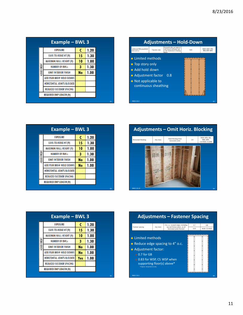
‐
=
‐
i i
8232016
61
Example ndash BWL 3
C 120 15 130 10 100 3 130
No 100
62
Adjustments ndash Hold‐Down
Limited methods
Top story only
Add hold down
Adjustment factor 08
Not applicable to continuous sheathing
R602103
63
Example ndash BWL 3
C 120 15 130 10 100 3 130
No 100 No 100
64
Adjustments ndash Omit Horiz Blocking
R6021010
Horizontal blocking Any story Omit blocking from
horizontal joints 20
WSP SFB GB PBS HPS
CS-WSP CS-SFB
65
Example ndash BWL 3
C 120 15 130 10 100 3 130
No 100 No 100 Yes 100
66
Fastener spacing Any story 4 in oc at panel edges including
top and bottom plates an all horizontal joints blocked
07 GB
083 WSP CS-WSP
Adjustments ndash Fastener Spacing
Limited methods
Reduce edge spacing to 4rdquo oc
Adjustment factor 07 for GB
083 for WSP CS WSP when supporting floor(s) above
Virginia nterpretat on only
R602103
11
‐
‐
70
8232016
67
Example ndash BWL 3
C 130 15 120 10 100 3 130
No 100 No 100 Yes 100 No 100
Required Length of Bracing Multiply tabular requirement by each adjustment factor
Required BWP Length = (tabular requirement) x (adjustment factor) x (adjustment factor) x (adjustment factor)hellip
Required BWL Length = 6rsquo x 130 x 120 x 100 x 130 x 100 x 100 x 100 x 100 = 1217rsquo
R602103 68
69
Example ndash BWL 3
C 120 15 130 10 100 3 130
No 100 No 100 Yes 100 No 100
75
1521 What Makes a Braced Wall Panel
BRACING METHODS
71
Engineered Bracing Types
Segmented shear walls Separate shear walls
Hold down at each end
Perforated shear walls One large shear wall
Hold down at each end
Openings permitted
R602104 72
Prescriptive Bracing Types
Intermittent bracing Based on segmented
Sheath at BWP locations only
Continuous sheathing Based on perforated
Sheath all exposed areas
R602104
12
‐
‐
‐
8232016
Intermittent Bracing Methods LIB let in bracing
WSP wood structural panels
SFB structural fiberboard
GB gypsum board
PFH portal frame with hold downs
PFG portal frame at
LIB Let‐in Bracing 1x4 wood or metal strap
45deg to 60deg angle
2 8d nails per stud
garages
73R602104
60deg max 45deg min R602104 74
75
LIB Let‐in Bracing TIP Place LIB bracing in an interior wall that does not have full height gypsum board is an easy way to provide ldquohiddenrdquo bracing
WSP Wood Structural Panels 716rdquo thick OSB or plywood
Fasteners 6d nails 6rdquo oc edges 12rdquo oc field
48rdquo minimum length
R602104 76
77
SFB Structural Fiberboard 12rdquo thick 16rdquo oc stud spacing only
Fasteners 8d nails 3rdquo oc edges 6rdquo oc field
48rdquo minimum length
R602104 78
GB Gypsum Board 12rdquo thick
Fasteners nails or screws 7rdquo oc edges and field
48rdquo minimum length
R602104
13
‐ ‐ ‐
8232016
79
GB Gypsum Board
TIP The fire separation between the garage and living space is an efficient way to get added bracing
PFH Portal Frame with Hold‐down
716rdquo thick OSB or plywood
Cast in place hold downs required
SinglePortal
one panel
Double Portal two
panels
R6021062 80
81
PFH Portal Frame with Hold‐down
16rdquo minimum length
10rsquo m
axim
um
pan
el height
82
TIP Portal Frames
Tested assembly
Cannot be engineered
Field deviations prohibited
R6021062
83
TIP Portal Frames at Garages
One Opening
84
TIP Portal Frames at Garages
Two Openings
Continuous header prohibited
14
‐
‐
‐
‐
‐
‐
8232016
85
TIP Portal Frames at Garages
Three Openings
Continuous header prohibited
Continuous header prohibited
PFG Portal Frame at Garage Opening 716rdquo thick OSB or plywood
At garage only
No hold downs
DoubleSinglePortal Portaltwo one panel
panels
R6021063 86
87
PFG Portal Frame at Garage Opening
24rdquo minimum length
10
rsquo ma
xim
um
pa
ne
l he
igh
t
88
Equivalent Products
Equivalent to BWP
Per ICC ES Evaluation Report
Simpson Strong Tie Steel Strong Wall
Wood Strong Wall
SB Shearwall
Hardy HFX Series Panels
Equivalent Products
90
Two‐Story Walls
TIP Some approved equivalent products can be stacked to brace two story balloon framed walls Product Manufacturer
Minimum Available Width
ICC ES ESR Number
Steel Strong Walls Simpson Strong‐Tie 12rdquo 1679
Wood Strong Walls Simpson Strong‐Tie 16rdquo 1267
SB Shearwalls Simpson Strong‐Tie 12rdquo 2652
9rdquoHFX Panels Hardy Frame 2089(nailer not included)
89
15
‐
‐
‐
‐
‐
8232016
Continuous Sheathing Bracing Methods CS‐WSP Wood Structural Panels 716rdquo thick OSB or plywood CS WSP wood structural
panels Fasteners 8d nails 6rdquo oc edges 12rdquo oc field
24rdquo minimum length fiberboard
CS SFB structural
CS G wood structural panels adjacent garage openings
CS PF continuous sheathing portal frame
91 R602104 92R602104
CS‐SFB Structural Fiberboard CS‐G Wood Structural Panels at Garage 12rdquo thick structural fiberboard 716rdquo thick OSB or plywood
Fasteners 6d nails 6rdquo oc edges 12rdquo oc field Fasteners 8d nails 3rdquo oc edges 6rdquo oc field 24rdquo minimum length one opening only 24rdquo minimum length No floors above
R602104 93 R602104 94
95
CS‐PF Continuous Sheathing Portal Frame 716rdquo thick OSB or plywood
No hold downs
Can be constructed on wood floor
4 panels maximum in one BWL
R60210634
SinglePortal
one panel
Double Portal two
panels
96
CS‐PF Continuous Sheathing Portal Frame
16rdquo minimum length
10
rsquo ma
xim
um
pa
ne
l he
igh
t
16
l
l
100
8232016
97
CS‐PF Continuous Sheathing Portal Frame Pony Walls on Portal Frames
Creates hinges
Strap resists hinge forces
Table R6021064 determines strap capacity
R6021064 98
Double Portal
99
Pony Walls on Portal Frames
Tab e R6021064
The Contribution of Each Braced Wall Panel
MINIMUM PANEL LENGTHS
DEFINITION The dimension required for a length of sheathed wall to be considered a braced wall panel which contributes to the MWFRS
101
BWP Minimum Length
Length
102
Minimum Length of Intermittent BWPs
Tab e R602105
(based on 60deg angle)
R602105
17
l
l l
l
8232016
103
Minimum Length of Narrow Methods
Tab e R602105 104
Minimum Length of CS‐WSP CS‐SFB
Based on height of adjacent opening(s)
Where opening on both sides use taller
105
Minimum Length of Continuous Sheathing
Tab e R602105
27rdquo minimum
9rsquo tall wall 62rdquo window
106
Minimum Length of Continuous Sheathing
Tab e R602105
30rdquo minimum
9rsquo tall wall 80rdquo door
DEFINITION The dimension a BWP contributes towards a BWLrsquos required length of bracing
107
BWP Contributing Length
Contributing Length
108
BWP Contributing Length
Tab e R602105
Virginia 2012 IRC 2015
R6021051
18
‐
8232016
109
BWP Contributing Length TIP Narrow methods PFH PFG CS PF and equivalent products are a way to provide more bracing than the actual wall length
110
BWP Projected Length
Angled BWPs contribute projected length only
Can project to one BWL only
R602103
A
3
B
BWP Contributing Length
1
24rdquo 36rdquo CS‐G 16rdquo 16rdquo CS‐WSP 38rdquo
CS‐PF CS‐PF CS‐WSP
The cumulative length of all BWPs in BWL 1 = 24 + (16 x 15) + (16 x 15) + 36 + 38 = 146rdquo = 12rsquo‐2rdquo
R6021051 111 112
Example ndash BWL 3
5rsquo‐9rdquo 11rsquo‐6rdquo 6rsquo20rsquo 7rsquo4rsquo
1 42
BWL 3
3
113
Example ndash BWL 3
575 115
CS-WSP
4 CS-WSP
2725
CS-WSP 6CS-WSP
Rules for BWPs on a BWL 1 LENGTH
Total contributing length of BWPs must exceed Required BWP Length
2 SPACING BWPs cannot exceed a maximum spacing
3 QUANTITY BWLs require a minimum number of BWPs
4 LOCATION BWPs must be located at each end
5 END CONDITIONS Ends of BWLs with continuous sheathing must be stiffened
R602102 R602103 114
19
8232016
115
Length
Cumulative length of all BWPsrsquo contributing length
Cumulative length ge Required BWP Length
R6021022
Cumulate Length of BWPs
Braced Wall Line 116
Example ndash BWL 3
575 115
CS-WSP
4 CS-WSP
2725
CS-WSP
1217
6CS-WSP
117
Example ndash BWL 3
Pass
118
Spacing
BWPs cannot exceed a distance of 20rsquo edge to edge
R6021022
5rsquo‐9rdquo 11rsquo‐6rdquo 6rsquo20rsquo 7rsquo4rsquo
1 42
BWL 3
3
119
Example ndash BWL 3
Pass
Yes
120
Number
BWLs must have a minimum of two BWPs
Exception BWLs le 16rsquo can have one 48rdquo BWP
R6021023
le16rsquo
ge48rdquo
Braced Wall Line Braced Wall Line
20
‐
= =
‐ ‐
8232016
121
Example ndash BWL 3
Pass
Yes Yes
122
Location
Located at BWL end or
Begins within 10rsquo of BWL end
R6021022
5rsquo‐9rdquo 11rsquo‐6rdquo 6rsquo20rsquo 7rsquo4rsquo
1 42
BWL 3
3
123
Example ndash BWL 3
Pass
Yes Yes Yes
124
End Conditions
Perforated shear walls hold downs at each end
Continuous sheathing 24rdquo panels each side of corner
R602107
=
125
End Conditions
End panel BWP sincehellip le 64rdquo opening
8rsquo tall wall
BWP 24rdquo panel length
Return panel
End Condition 1
R602107 126
End Conditions End panel BWP
No return panel
End Condition 2
Add 800 lbs hold down device
R602107
21
‐
=
‐
=
‐‐
‐‐
48rdquoBWP
24rdquopanel BWP
8232016
End Conditions
48rdquo sheathing at end also equivalent to hold down device
End panel BWP
No return panel or hold down
End Condition 3
End panel =
R602107 127
End Conditions
End panel ne BWP
End panel 24rdquo
Return panel
First BWP begins le 10rsquo from end
End Condition 4
End
gt32rdquo
First
R602107 128
129
End Conditions
No end panel
No return panel
First BWP begins le 10rsquo from end
End Condition 5
Add 800 lbs hold down device
R602107
End Conditions TIP Where 2 BWLs with continuous sheathing meet at a corner and one side requires a hold down the opposite side will usually require a hold down or 48rdquo end panel (End Condition 3)
130
131
Example ndash BWL 3
Pass
Yes Yes Yes
1 1
132
Example ndash BWL 3
Pass
Yes Yes Yes
1 1 Pass
22
8232016
23
‐
‐
133
137
Combining Methods and Materials in the Same Braced Wall Line
MIXING RULES
134
Mixing Methods
Mixing methods from BWL to BWL is permitted
R602104
BWL must include return panels if applicable
135
Mixing Methods
Mixing intermittent methods along a BWL is permitted
R602104
BWL must be designed for weakest method
136
Mixing Methods
Any narrow method can mix with CS WSP
No other methods can mix with CS SFB
R602104
ABW PFH PFG CS‐PF permitted in CS‐WSP
NO mixing in CS‐SFB
Mixing Methods Mixing intermittent and continuous permitted CS on exterior
Intermittent on interior
Design for weakest methods
End conditions required
R602104 B 138
Cripple Walls
DEFINITIONA framed wall extending from the top of the foundation to the underside of the floor framing of the first story above grade
Option 1
8232016
Cripple Wall Bracing ndash Option 1 Cripple Wall Bracing ndash Option 2
Cripple Wall Story Required BWP Length = 1st floor x 115
Top Story
1st Story
2nd Story becomes 3rd Story
1st Story becomes 2nd Story
Cripple Wall Story = 1st Story
R6021011 139 R60210113 140
141
Completing the Load Path Roof
Roof diaphragm to BWPs
R6021081 142
Roof Blocking
Roof diaphragm to BWPs
R6021081
0 ndash
925
rdquo
gt 925rdquo ndash 1525rdquo 2x blocking
le 925rdquo No blocking required
143
Roof Blocking
Roof diaphragm to BWPs
R6021081
1525rdquo ndash 48rdquo Soffit panel orhellip 144
Roof Blocking
Roof diaphragm to BWPs
R6021081
1525rdquo ndash 48rdquo Vertical blocking panel
24
8232016
145
Completing the Load Path Interior BWPs
Interior BWPs to floors
R6021081 146
Interior BWP Blocking
Interior BWPs to floors
Where joists are perpendicular Full height blocking
Between joists
Full length of BWP
R602108
147
Interior BWP Blocking
Where joists are parallel Option 1 provide additional joists
R602108 148
Interior BWP Blocking
Where joists are parallel Option 1 provide additional joists
Option 2 provide additional blocking bull Perpendicular 16rdquo oc
bull Full length of BWP
R602108
149
Interior BWP Blocking
TIP Placing an interior BWP within a bearing wall will eliminate the need for added blocking
R602108 150
Completing the Load Path Stem Walls
Masonry or concrete
BWPs to stem walls
Reinforce stem walls lt 48rdquo long BWPs
Stem walls up to 48rdquo high
Stem walls gt 48rdquo high require RDP design
R602109
25
‐
‐ ‐
‐i i
‐
‐
8232016
Completing the Load Path Stem Walls Stem Walls
Stem wall height le 24rdquo Stem wall up to 48rdquo high Cast in place 4 dowels
Cast in place 4 dowels Bend dowels into bond beam Additional ldquohair pinrdquo
4 rebar lapped to dowels
R602109 151 R602109 152
Stem Walls
Non rebar option
Stem wall up to 48rdquo high
Cast in place 58rdquo threaded rod
Epoxy option with 5000 lbs pull out value (V rg nia amendment)
2rdquo cut washers
R602109 153
Completing the Load Path Cantilevers
155
Completing the Load Path Piers
Walls above piers per R60210
Piers by RDP
Common error sunrooms on posts
Common solution cross bracing
R602109 156
Wall Bracing Omissions
Construction conditions not addressed in IRC
Sheath the following Gable end walls
Gable dormers
Narrow shed dormers
Treat the following as full wall or part of BWL Full width shed dormers
Short cantilevered diaphragms can transfer load to BWPs
Cantilevers per R50233 permissible
R602109 154
26
rdquo
rdquo
rdquo
1
5
8232016
PART 3 R60212 ndash ldquoPRACTICALrdquo WALL BRACING
2
ldquoPracticalrdquo Wall Bracing
Virginia only
Simpler
Braced wall panels (BWP)
Circumscribed rectangles
Based on ldquoClassicrdquo
R60212
3
Alternate Prescription Solutions
APA Simplified Wall Bracing
IRC Simplified Wall Bracing (national version)
4
Practical Spreadsheet
Adapting Braced Wall Panels to Practical Wall Bracing
MATERIALS AND PANELS
6
Sheathing Materials Exterior
716 OSB or plywood (fasten 6rdquo edge 12rdquo field)
12 structural fiberboard (fasten 3rdquo edge 6rdquo field)
Sheath entire exterior (continuous sheathing)
Cannot mix materials
Interior
12 gypsum board (fasten 7rdquo edge field)
R602121
1
‐
8
9
8232016
7
Braced Wall Panel
R602102
Same as ldquoclassicrdquo Full height
No offsets
Splices permitted
Minimum Length Interior 48rdquo
Exterior per Table R602122
ldquoClassicrdquo carryovers Narrow methods ABW PFH PFG CS PF
Circumscribed Rectangle
R602123
DEFINITION A rectangle that surrounds a building or portions thereof with a minimum length of bracing assigned to each side
Circumscribed Rectangles
Unlimited rectangles permitted
Identify common rectangle sides
R6021011
Common rectangle sides
Circumscribed Rectangles
Include enclosed offsets and projections Sunrooms
Garages
Bay windows
First floor Garage
Sunroom
Exclude open structures Decks
Chim
ney
First floor
Deck
Carports
Screened porches Carport
Exclude chimneys R602123
Porch 10
11
Circumscribed Rectangles
Different rectangle(s) for each floor
R602123
First Floor Second Floor
12
Circumscribed Rectangles
Can be applied to additions
R602123
2
=
‐
8232016
13
Circumscribed Rectangles
Maximum size 80rsquo x 80rsquo
R602123
le 80rsquo
le 80rsquo
14
Circumscribed Rectangles Maximum aspect ratio long side 31
short side
R602123
3
1
15
Circumscribed Rectangles
Rectangles can be skewed
R602123 16
Circumscribed Rectangles
Applies to walk out conditions
R602123
17
Circumscribed Rectangles
TIP One rectangle relies solely on exterior bracing Multiple rectangles results in complicated interiors Deciding the most efficient number of rectangle may be an iterative process
18
Example 100 mph Farm house 15rsquo eave to ridge
10rsquo walls Exterior walls sheathed in OSB
Finished interior
Standard fastener spacing
66rsquo
60rsquo
3
8232016
19
Example Draw rectangle
Determine aspect ratio
66rsquo
60rsquo
100 66 60 110 20
Exterior BWPs on or Facing Rectangle Side
R6021241
Top
21
Exterior BWPs on or Facing Rectangle Side
R6021241
Right
22
Exterior BWPs on or Facing Rectangle Side
R6021241
Bottom
23
Exterior BWPs on or Facing Rectangle Side
R6021241
Left Exterior BWPs on or Facing Rectangle Side
TIP 1 Assign a partially obscured BWP to the parallel rectangle side itrsquos unobscured portion faces
TIP 2 Assign an wholly obscured BWP to either parallel rectangle side
Partially Obscured Obscured 24
4
‐
8232016
25
Interior BWP on Rectangle Side
R6021241 26
Interior BWP Facing Rectangle Side
R6021241
4rsquo max
27
Projections of Angled BWPs
R6021241 28
Projections of Angled BWPs
R6021241
29
Shared BWPs at Skewed Rectangles
R6021243 30
Shared BWPs at Skewed Rectangles
Apply BWP to skewed rectangle (green) it is located on
Apply BWL projections to non skewed rectangle (red)
R6021243
5
8232016
31
BWP on Common Rectangle Sides
32
Example ndash Rear Rectangle Side
66rsquo
60rsquo
33
Example ndash Rear Rectangle Side
66rsquo
60rsquo
34
Tabular Requirement Use Table R602124
35
Example ndash Rear Rectangle Side
R602103 36
Example ndash Rear Rectangle Side
143
15 0
Wood Structural Panels
6
l
l
‐ ‐
l
8232016
37
Adjustments
Use footnotes from Table R602124 Exposure Category C
Wall heights
Fastener spacing
R602124 38
Adjustments ‐Wind Exposure
Tab e R602124 Footnote b
Category C Open terrain
Grasslands flat plains
Wind flows over openwater for 1500 feet
120 one‐story
130 two‐story
140 three‐story
39
Example ndash Rear Rectangle Side
C 143
120
40
Adjustments ndash Wall Height
Tab e R602124 Footnote c
100 10rsquo wall
105 11rsquo wall
110 12rsquo wall
090 8rsquo wall
095 9rsquo wall
Adjustments
TIP When walls assigned to a rectangle side have more than one wall height eave to ridge height etc adjust to the highest value for the required length of bracing
42
Example ndash Rear Rectangle Side
C 143
120 10 100
Tab e R602124 Footnote f 41
7
i i
8232016
43
Adjustments ndash No Interior Finish
R602122 4
140
44
Example ndash Rear Rectangle Side
C 143
120 10 100 NO 100
45
Adjustments ndash Fastener Spacing
R602103 Footnote d
4rdquo fastener spacing
083 OSB or plywood (exterior) when supporting floor(s) above
07 gypsum board (interior)
Virginia nterpretat on
46
Example ndash Rear Rectangle Side
C 143
120 10 100 NO 100 NO 100
Required Length of Bracing Multiply tabular requirements by each adjustment factor
Adjusted length = (tabular value) x (adjustment factor) x (adjustment factor) x (adjustment factor)hellip
Required BWL Length = 143rsquo x 120 x 100 x 100 x 100 = 172rsquo
48
Example ndash Rear Rectangle Side
C 143
120 10 100 NO 100 NO 100
172
47
8
=
l l
8232016
49
Common Rectangle Sides Add Required BWP Length for each side Adjusted length Adjusted length + Adjusted length
LA LA
50
Example ndash Rear Rectangle Side
Repeat for common rectangle side and add required value here
R602124
C 143
120 10 100 NO 100 NO 100
172 0
172
51
Exterior BWP Minimum Length
Based on adjacent opening(s) Adjacent garage opening or
Height of adjacent opening
52
Exterior BWP Minimum Length
R602122
53
Exterior BWP Minimum Length
Tab e R602105
27rdquo minimum
9rsquo tall wall 62rdquo window
54
Exterior BWP Minimum Length
Tab e R602105
36rdquo minimum
9rsquo tall wall 84rdquo door
9
=
=
=
‐ =
=
8232016
55
Braced Wall Panel
R602102
Contributing Length Exterior actual
Interior 05 x actual
ldquoClassicrdquo narrow methods bull PFH 48rdquo
bull PFG CS PF 15 x actual
bull Equivalent products 48rdquo
56
Example ndash Rear Rectangle Side
5rsquo‐9rdquo 11rsquo‐6rdquo 6rsquo20rsquo 7rsquo4rsquo
1 42
REAR RECTANGLE SIDE
3
57
Example ndash Rear Rectangle Wall
575 115
EXTERIOR
4
2725
6
EXTERIOR EXTERIOR EXTERIOR
176
PASS 58
Distribution Rule 1
BWPs located le 12rsquo from house corner
R602126 1
le12rsquo le12rsquo le12rsquo le12rsquo
le12rsquo
59
Distribution Rule 1
BWPs located le 12rsquo from interior rectangle corner
60
Distribution Rule 1
BWPs located le 12rsquo from interior rectangle corner
10
8232016
61
Distribution Rule 1
BWPs located le 12rsquo from interior rectangle corner
62
Distribution Rule 1
BWPs located le 12rsquo from interior rectangle corner
63
Distribution Rule 2
Edge to edge distance between adjacent BWPs le 20rsquo
R602126 2
le20rsquo
64
Distribution Rule 3
Wall gt 8rsquo require at least one BWP
R602126 3
gt8rsquo
gt8rsquo
65
Distribution Rule 3
Wall gt 8rsquo require at least one BWP
Walls le 8rsquo are permitted no BWPs
R602126 4
gt8rsquo
gt8rsquo
le8rsquo
66
Example ndash Rear Rectangle Side
5rsquo‐9rdquo 11rsquo‐6rdquo 6rsquo20rsquo 7rsquo4rsquo
1 42
REAR RECTANGLE SIDE
3
11
68
‐
‐
‐
70
R602127 R602128
8232016
BWPs Adjacent Balloon‐Framed Walls
67
Example ndash Rear Rectangle Side
PASS YES YES YES PASS
Balloon framed walls Two story foyers
Family rooms
BWP locations Each side of two story portion
Each floor
R6021261
69
BWPs Adjacent Balloon‐Framed Walls
R6021261
balloon‐framed
walls
floor floor
Practical Wall Bracing Meets ldquoClassicrdquo
ldquoCLASSICrdquo CARRYOVERS
71
BWP Connections
Refer to R602108
Connections to framing
Connections to roof
72
BWP Support
Refer to R602109
Cantilevered floor restriction
Masonry stem walls
12
‐
‐ ‐
‐ ‐
‐ ‐
‐ ‐
‐ ‐ ‐ ‐ ‐
73
77
8232016
Tying Up Loose Ends
SUM UP
Classic vs Practical R60210 R60212
8 materials 3 materials
4 narrow methods 4 narrow methods
Unlimited size houses Unlimited size houses
Braced wall panels Braced wall panels
Braced wall lines Circumscribed rectangles
All detached homes All detached homes
All townhouses Townhouses in SDC A amp B only
End conditions No end conditions
BWPs 10rsquo from BWL end BWPs 12rsquo from all
houserectangle corners
Greater flexibility Easier application
Nationwide Virginia only 74
75
Publications
Guide to the 2012 IRC Wall Bracing Provisions (APA)
Wind Bracing (Fairfax County)
Prescriptive Design Guide (Simpson Strong Tie)
IRC Wall Bracing Guide for Builders Designers and Plan Reviewers (Foam Sheathing Coalition)
Notes from this class (available on fairfaxcountygov)
Resources
Chuck Bajnai 804 717 6428 bajnaicchesterfieldgov
Brian Foley 703 324 1842 brianfoleyfairfaxcountygov
APA ndash The Engineered Wood Association 253 620 7400 apawoodorg
Simpson Strong Tie (800) 999 5099 strongtiecom
ICC ES 1 800 423 6587 x66546 icc esorg
76
THE END
13

‐
‐
70
8232016
67
Example ndash BWL 3
C 130 15 120 10 100 3 130
No 100 No 100 Yes 100 No 100
Required Length of Bracing Multiply tabular requirement by each adjustment factor
Required BWP Length = (tabular requirement) x (adjustment factor) x (adjustment factor) x (adjustment factor)hellip
Required BWL Length = 6rsquo x 130 x 120 x 100 x 130 x 100 x 100 x 100 x 100 = 1217rsquo
R602103 68
69
Example ndash BWL 3
C 120 15 130 10 100 3 130
No 100 No 100 Yes 100 No 100
75
1521 What Makes a Braced Wall Panel
BRACING METHODS
71
Engineered Bracing Types
Segmented shear walls Separate shear walls
Hold down at each end
Perforated shear walls One large shear wall
Hold down at each end
Openings permitted
R602104 72
Prescriptive Bracing Types
Intermittent bracing Based on segmented
Sheath at BWP locations only
Continuous sheathing Based on perforated
Sheath all exposed areas
R602104
12
‐
‐
‐
8232016
Intermittent Bracing Methods LIB let in bracing
WSP wood structural panels
SFB structural fiberboard
GB gypsum board
PFH portal frame with hold downs
PFG portal frame at
LIB Let‐in Bracing 1x4 wood or metal strap
45deg to 60deg angle
2 8d nails per stud
garages
73R602104
60deg max 45deg min R602104 74
75
LIB Let‐in Bracing TIP Place LIB bracing in an interior wall that does not have full height gypsum board is an easy way to provide ldquohiddenrdquo bracing
WSP Wood Structural Panels 716rdquo thick OSB or plywood
Fasteners 6d nails 6rdquo oc edges 12rdquo oc field
48rdquo minimum length
R602104 76
77
SFB Structural Fiberboard 12rdquo thick 16rdquo oc stud spacing only
Fasteners 8d nails 3rdquo oc edges 6rdquo oc field
48rdquo minimum length
R602104 78
GB Gypsum Board 12rdquo thick
Fasteners nails or screws 7rdquo oc edges and field
48rdquo minimum length
R602104
13
‐ ‐ ‐
8232016
79
GB Gypsum Board
TIP The fire separation between the garage and living space is an efficient way to get added bracing
PFH Portal Frame with Hold‐down
716rdquo thick OSB or plywood
Cast in place hold downs required
SinglePortal
one panel
Double Portal two
panels
R6021062 80
81
PFH Portal Frame with Hold‐down
16rdquo minimum length
10rsquo m
axim
um
pan
el height
82
TIP Portal Frames
Tested assembly
Cannot be engineered
Field deviations prohibited
R6021062
83
TIP Portal Frames at Garages
One Opening
84
TIP Portal Frames at Garages
Two Openings
Continuous header prohibited
14
‐
‐
‐
‐
‐
‐
8232016
85
TIP Portal Frames at Garages
Three Openings
Continuous header prohibited
Continuous header prohibited
PFG Portal Frame at Garage Opening 716rdquo thick OSB or plywood
At garage only
No hold downs
DoubleSinglePortal Portaltwo one panel
panels
R6021063 86
87
PFG Portal Frame at Garage Opening
24rdquo minimum length
10
rsquo ma
xim
um
pa
ne
l he
igh
t
88
Equivalent Products
Equivalent to BWP
Per ICC ES Evaluation Report
Simpson Strong Tie Steel Strong Wall
Wood Strong Wall
SB Shearwall
Hardy HFX Series Panels
Equivalent Products
90
Two‐Story Walls
TIP Some approved equivalent products can be stacked to brace two story balloon framed walls Product Manufacturer
Minimum Available Width
ICC ES ESR Number
Steel Strong Walls Simpson Strong‐Tie 12rdquo 1679
Wood Strong Walls Simpson Strong‐Tie 16rdquo 1267
SB Shearwalls Simpson Strong‐Tie 12rdquo 2652
9rdquoHFX Panels Hardy Frame 2089(nailer not included)
89
15
‐
‐
‐
‐
‐
8232016
Continuous Sheathing Bracing Methods CS‐WSP Wood Structural Panels 716rdquo thick OSB or plywood CS WSP wood structural
panels Fasteners 8d nails 6rdquo oc edges 12rdquo oc field
24rdquo minimum length fiberboard
CS SFB structural
CS G wood structural panels adjacent garage openings
CS PF continuous sheathing portal frame
91 R602104 92R602104
CS‐SFB Structural Fiberboard CS‐G Wood Structural Panels at Garage 12rdquo thick structural fiberboard 716rdquo thick OSB or plywood
Fasteners 6d nails 6rdquo oc edges 12rdquo oc field Fasteners 8d nails 3rdquo oc edges 6rdquo oc field 24rdquo minimum length one opening only 24rdquo minimum length No floors above
R602104 93 R602104 94
95
CS‐PF Continuous Sheathing Portal Frame 716rdquo thick OSB or plywood
No hold downs
Can be constructed on wood floor
4 panels maximum in one BWL
R60210634
SinglePortal
one panel
Double Portal two
panels
96
CS‐PF Continuous Sheathing Portal Frame
16rdquo minimum length
10
rsquo ma
xim
um
pa
ne
l he
igh
t
16
l
l
100
8232016
97
CS‐PF Continuous Sheathing Portal Frame Pony Walls on Portal Frames
Creates hinges
Strap resists hinge forces
Table R6021064 determines strap capacity
R6021064 98
Double Portal
99
Pony Walls on Portal Frames
Tab e R6021064
The Contribution of Each Braced Wall Panel
MINIMUM PANEL LENGTHS
DEFINITION The dimension required for a length of sheathed wall to be considered a braced wall panel which contributes to the MWFRS
101
BWP Minimum Length
Length
102
Minimum Length of Intermittent BWPs
Tab e R602105
(based on 60deg angle)
R602105
17
l
l l
l
8232016
103
Minimum Length of Narrow Methods
Tab e R602105 104
Minimum Length of CS‐WSP CS‐SFB
Based on height of adjacent opening(s)
Where opening on both sides use taller
105
Minimum Length of Continuous Sheathing
Tab e R602105
27rdquo minimum
9rsquo tall wall 62rdquo window
106
Minimum Length of Continuous Sheathing
Tab e R602105
30rdquo minimum
9rsquo tall wall 80rdquo door
DEFINITION The dimension a BWP contributes towards a BWLrsquos required length of bracing
107
BWP Contributing Length
Contributing Length
108
BWP Contributing Length
Tab e R602105
Virginia 2012 IRC 2015
R6021051
18
‐
8232016
109
BWP Contributing Length TIP Narrow methods PFH PFG CS PF and equivalent products are a way to provide more bracing than the actual wall length
110
BWP Projected Length
Angled BWPs contribute projected length only
Can project to one BWL only
R602103
A
3
B
BWP Contributing Length
1
24rdquo 36rdquo CS‐G 16rdquo 16rdquo CS‐WSP 38rdquo
CS‐PF CS‐PF CS‐WSP
The cumulative length of all BWPs in BWL 1 = 24 + (16 x 15) + (16 x 15) + 36 + 38 = 146rdquo = 12rsquo‐2rdquo
R6021051 111 112
Example ndash BWL 3
5rsquo‐9rdquo 11rsquo‐6rdquo 6rsquo20rsquo 7rsquo4rsquo
1 42
BWL 3
3
113
Example ndash BWL 3
575 115
CS-WSP
4 CS-WSP
2725
CS-WSP 6CS-WSP
Rules for BWPs on a BWL 1 LENGTH
Total contributing length of BWPs must exceed Required BWP Length
2 SPACING BWPs cannot exceed a maximum spacing
3 QUANTITY BWLs require a minimum number of BWPs
4 LOCATION BWPs must be located at each end
5 END CONDITIONS Ends of BWLs with continuous sheathing must be stiffened
R602102 R602103 114
19
8232016
115
Length
Cumulative length of all BWPsrsquo contributing length
Cumulative length ge Required BWP Length
R6021022
Cumulate Length of BWPs
Braced Wall Line 116
Example ndash BWL 3
575 115
CS-WSP
4 CS-WSP
2725
CS-WSP
1217
6CS-WSP
117
Example ndash BWL 3
Pass
118
Spacing
BWPs cannot exceed a distance of 20rsquo edge to edge
R6021022
5rsquo‐9rdquo 11rsquo‐6rdquo 6rsquo20rsquo 7rsquo4rsquo
1 42
BWL 3
3
119
Example ndash BWL 3
Pass
Yes
120
Number
BWLs must have a minimum of two BWPs
Exception BWLs le 16rsquo can have one 48rdquo BWP
R6021023
le16rsquo
ge48rdquo
Braced Wall Line Braced Wall Line
20
‐
= =
‐ ‐
8232016
121
Example ndash BWL 3
Pass
Yes Yes
122
Location
Located at BWL end or
Begins within 10rsquo of BWL end
R6021022
5rsquo‐9rdquo 11rsquo‐6rdquo 6rsquo20rsquo 7rsquo4rsquo
1 42
BWL 3
3
123
Example ndash BWL 3
Pass
Yes Yes Yes
124
End Conditions
Perforated shear walls hold downs at each end
Continuous sheathing 24rdquo panels each side of corner
R602107
=
125
End Conditions
End panel BWP sincehellip le 64rdquo opening
8rsquo tall wall
BWP 24rdquo panel length
Return panel
End Condition 1
R602107 126
End Conditions End panel BWP
No return panel
End Condition 2
Add 800 lbs hold down device
R602107
21
‐
=
‐
=
‐‐
‐‐
48rdquoBWP
24rdquopanel BWP
8232016
End Conditions
48rdquo sheathing at end also equivalent to hold down device
End panel BWP
No return panel or hold down
End Condition 3
End panel =
R602107 127
End Conditions
End panel ne BWP
End panel 24rdquo
Return panel
First BWP begins le 10rsquo from end
End Condition 4
End
gt32rdquo
First
R602107 128
129
End Conditions
No end panel
No return panel
First BWP begins le 10rsquo from end
End Condition 5
Add 800 lbs hold down device
R602107
End Conditions TIP Where 2 BWLs with continuous sheathing meet at a corner and one side requires a hold down the opposite side will usually require a hold down or 48rdquo end panel (End Condition 3)
130
131
Example ndash BWL 3
Pass
Yes Yes Yes
1 1
132
Example ndash BWL 3
Pass
Yes Yes Yes
1 1 Pass
22
8232016
23
‐
‐
133
137
Combining Methods and Materials in the Same Braced Wall Line
MIXING RULES
134
Mixing Methods
Mixing methods from BWL to BWL is permitted
R602104
BWL must include return panels if applicable
135
Mixing Methods
Mixing intermittent methods along a BWL is permitted
R602104
BWL must be designed for weakest method
136
Mixing Methods
Any narrow method can mix with CS WSP
No other methods can mix with CS SFB
R602104
ABW PFH PFG CS‐PF permitted in CS‐WSP
NO mixing in CS‐SFB
Mixing Methods Mixing intermittent and continuous permitted CS on exterior
Intermittent on interior
Design for weakest methods
End conditions required
R602104 B 138
Cripple Walls
DEFINITIONA framed wall extending from the top of the foundation to the underside of the floor framing of the first story above grade
Option 1
8232016
Cripple Wall Bracing ndash Option 1 Cripple Wall Bracing ndash Option 2
Cripple Wall Story Required BWP Length = 1st floor x 115
Top Story
1st Story
2nd Story becomes 3rd Story
1st Story becomes 2nd Story
Cripple Wall Story = 1st Story
R6021011 139 R60210113 140
141
Completing the Load Path Roof
Roof diaphragm to BWPs
R6021081 142
Roof Blocking
Roof diaphragm to BWPs
R6021081
0 ndash
925
rdquo
gt 925rdquo ndash 1525rdquo 2x blocking
le 925rdquo No blocking required
143
Roof Blocking
Roof diaphragm to BWPs
R6021081
1525rdquo ndash 48rdquo Soffit panel orhellip 144
Roof Blocking
Roof diaphragm to BWPs
R6021081
1525rdquo ndash 48rdquo Vertical blocking panel
24
8232016
145
Completing the Load Path Interior BWPs
Interior BWPs to floors
R6021081 146
Interior BWP Blocking
Interior BWPs to floors
Where joists are perpendicular Full height blocking
Between joists
Full length of BWP
R602108
147
Interior BWP Blocking
Where joists are parallel Option 1 provide additional joists
R602108 148
Interior BWP Blocking
Where joists are parallel Option 1 provide additional joists
Option 2 provide additional blocking bull Perpendicular 16rdquo oc
bull Full length of BWP
R602108
149
Interior BWP Blocking
TIP Placing an interior BWP within a bearing wall will eliminate the need for added blocking
R602108 150
Completing the Load Path Stem Walls
Masonry or concrete
BWPs to stem walls
Reinforce stem walls lt 48rdquo long BWPs
Stem walls up to 48rdquo high
Stem walls gt 48rdquo high require RDP design
R602109
25
‐
‐ ‐
‐i i
‐
‐
8232016
Completing the Load Path Stem Walls Stem Walls
Stem wall height le 24rdquo Stem wall up to 48rdquo high Cast in place 4 dowels
Cast in place 4 dowels Bend dowels into bond beam Additional ldquohair pinrdquo
4 rebar lapped to dowels
R602109 151 R602109 152
Stem Walls
Non rebar option
Stem wall up to 48rdquo high
Cast in place 58rdquo threaded rod
Epoxy option with 5000 lbs pull out value (V rg nia amendment)
2rdquo cut washers
R602109 153
Completing the Load Path Cantilevers
155
Completing the Load Path Piers
Walls above piers per R60210
Piers by RDP
Common error sunrooms on posts
Common solution cross bracing
R602109 156
Wall Bracing Omissions
Construction conditions not addressed in IRC
Sheath the following Gable end walls
Gable dormers
Narrow shed dormers
Treat the following as full wall or part of BWL Full width shed dormers
Short cantilevered diaphragms can transfer load to BWPs
Cantilevers per R50233 permissible
R602109 154
26
rdquo
rdquo
rdquo
1
5
8232016
PART 3 R60212 ndash ldquoPRACTICALrdquo WALL BRACING
2
ldquoPracticalrdquo Wall Bracing
Virginia only
Simpler
Braced wall panels (BWP)
Circumscribed rectangles
Based on ldquoClassicrdquo
R60212
3
Alternate Prescription Solutions
APA Simplified Wall Bracing
IRC Simplified Wall Bracing (national version)
4
Practical Spreadsheet
Adapting Braced Wall Panels to Practical Wall Bracing
MATERIALS AND PANELS
6
Sheathing Materials Exterior
716 OSB or plywood (fasten 6rdquo edge 12rdquo field)
12 structural fiberboard (fasten 3rdquo edge 6rdquo field)
Sheath entire exterior (continuous sheathing)
Cannot mix materials
Interior
12 gypsum board (fasten 7rdquo edge field)
R602121
1
‐
8
9
8232016
7
Braced Wall Panel
R602102
Same as ldquoclassicrdquo Full height
No offsets
Splices permitted
Minimum Length Interior 48rdquo
Exterior per Table R602122
ldquoClassicrdquo carryovers Narrow methods ABW PFH PFG CS PF
Circumscribed Rectangle
R602123
DEFINITION A rectangle that surrounds a building or portions thereof with a minimum length of bracing assigned to each side
Circumscribed Rectangles
Unlimited rectangles permitted
Identify common rectangle sides
R6021011
Common rectangle sides
Circumscribed Rectangles
Include enclosed offsets and projections Sunrooms
Garages
Bay windows
First floor Garage
Sunroom
Exclude open structures Decks
Chim
ney
First floor
Deck
Carports
Screened porches Carport
Exclude chimneys R602123
Porch 10
11
Circumscribed Rectangles
Different rectangle(s) for each floor
R602123
First Floor Second Floor
12
Circumscribed Rectangles
Can be applied to additions
R602123
2
=
‐
8232016
13
Circumscribed Rectangles
Maximum size 80rsquo x 80rsquo
R602123
le 80rsquo
le 80rsquo
14
Circumscribed Rectangles Maximum aspect ratio long side 31
short side
R602123
3
1
15
Circumscribed Rectangles
Rectangles can be skewed
R602123 16
Circumscribed Rectangles
Applies to walk out conditions
R602123
17
Circumscribed Rectangles
TIP One rectangle relies solely on exterior bracing Multiple rectangles results in complicated interiors Deciding the most efficient number of rectangle may be an iterative process
18
Example 100 mph Farm house 15rsquo eave to ridge
10rsquo walls Exterior walls sheathed in OSB
Finished interior
Standard fastener spacing
66rsquo
60rsquo
3
8232016
19
Example Draw rectangle
Determine aspect ratio
66rsquo
60rsquo
100 66 60 110 20
Exterior BWPs on or Facing Rectangle Side
R6021241
Top
21
Exterior BWPs on or Facing Rectangle Side
R6021241
Right
22
Exterior BWPs on or Facing Rectangle Side
R6021241
Bottom
23
Exterior BWPs on or Facing Rectangle Side
R6021241
Left Exterior BWPs on or Facing Rectangle Side
TIP 1 Assign a partially obscured BWP to the parallel rectangle side itrsquos unobscured portion faces
TIP 2 Assign an wholly obscured BWP to either parallel rectangle side
Partially Obscured Obscured 24
4
‐
8232016
25
Interior BWP on Rectangle Side
R6021241 26
Interior BWP Facing Rectangle Side
R6021241
4rsquo max
27
Projections of Angled BWPs
R6021241 28
Projections of Angled BWPs
R6021241
29
Shared BWPs at Skewed Rectangles
R6021243 30
Shared BWPs at Skewed Rectangles
Apply BWP to skewed rectangle (green) it is located on
Apply BWL projections to non skewed rectangle (red)
R6021243
5
8232016
31
BWP on Common Rectangle Sides
32
Example ndash Rear Rectangle Side
66rsquo
60rsquo
33
Example ndash Rear Rectangle Side
66rsquo
60rsquo
34
Tabular Requirement Use Table R602124
35
Example ndash Rear Rectangle Side
R602103 36
Example ndash Rear Rectangle Side
143
15 0
Wood Structural Panels
6
l
l
‐ ‐
l
8232016
37
Adjustments
Use footnotes from Table R602124 Exposure Category C
Wall heights
Fastener spacing
R602124 38
Adjustments ‐Wind Exposure
Tab e R602124 Footnote b
Category C Open terrain
Grasslands flat plains
Wind flows over openwater for 1500 feet
120 one‐story
130 two‐story
140 three‐story
39
Example ndash Rear Rectangle Side
C 143
120
40
Adjustments ndash Wall Height
Tab e R602124 Footnote c
100 10rsquo wall
105 11rsquo wall
110 12rsquo wall
090 8rsquo wall
095 9rsquo wall
Adjustments
TIP When walls assigned to a rectangle side have more than one wall height eave to ridge height etc adjust to the highest value for the required length of bracing
42
Example ndash Rear Rectangle Side
C 143
120 10 100
Tab e R602124 Footnote f 41
7
i i
8232016
43
Adjustments ndash No Interior Finish
R602122 4
140
44
Example ndash Rear Rectangle Side
C 143
120 10 100 NO 100
45
Adjustments ndash Fastener Spacing
R602103 Footnote d
4rdquo fastener spacing
083 OSB or plywood (exterior) when supporting floor(s) above
07 gypsum board (interior)
Virginia nterpretat on
46
Example ndash Rear Rectangle Side
C 143
120 10 100 NO 100 NO 100
Required Length of Bracing Multiply tabular requirements by each adjustment factor
Adjusted length = (tabular value) x (adjustment factor) x (adjustment factor) x (adjustment factor)hellip
Required BWL Length = 143rsquo x 120 x 100 x 100 x 100 = 172rsquo
48
Example ndash Rear Rectangle Side
C 143
120 10 100 NO 100 NO 100
172
47
8
=
l l
8232016
49
Common Rectangle Sides Add Required BWP Length for each side Adjusted length Adjusted length + Adjusted length
LA LA
50
Example ndash Rear Rectangle Side
Repeat for common rectangle side and add required value here
R602124
C 143
120 10 100 NO 100 NO 100
172 0
172
51
Exterior BWP Minimum Length
Based on adjacent opening(s) Adjacent garage opening or
Height of adjacent opening
52
Exterior BWP Minimum Length
R602122
53
Exterior BWP Minimum Length
Tab e R602105
27rdquo minimum
9rsquo tall wall 62rdquo window
54
Exterior BWP Minimum Length
Tab e R602105
36rdquo minimum
9rsquo tall wall 84rdquo door
9
=
=
=
‐ =
=
8232016
55
Braced Wall Panel
R602102
Contributing Length Exterior actual
Interior 05 x actual
ldquoClassicrdquo narrow methods bull PFH 48rdquo
bull PFG CS PF 15 x actual
bull Equivalent products 48rdquo
56
Example ndash Rear Rectangle Side
5rsquo‐9rdquo 11rsquo‐6rdquo 6rsquo20rsquo 7rsquo4rsquo
1 42
REAR RECTANGLE SIDE
3
57
Example ndash Rear Rectangle Wall
575 115
EXTERIOR
4
2725
6
EXTERIOR EXTERIOR EXTERIOR
176
PASS 58
Distribution Rule 1
BWPs located le 12rsquo from house corner
R602126 1
le12rsquo le12rsquo le12rsquo le12rsquo
le12rsquo
59
Distribution Rule 1
BWPs located le 12rsquo from interior rectangle corner
60
Distribution Rule 1
BWPs located le 12rsquo from interior rectangle corner
10
8232016
61
Distribution Rule 1
BWPs located le 12rsquo from interior rectangle corner
62
Distribution Rule 1
BWPs located le 12rsquo from interior rectangle corner
63
Distribution Rule 2
Edge to edge distance between adjacent BWPs le 20rsquo
R602126 2
le20rsquo
64
Distribution Rule 3
Wall gt 8rsquo require at least one BWP
R602126 3
gt8rsquo
gt8rsquo
65
Distribution Rule 3
Wall gt 8rsquo require at least one BWP
Walls le 8rsquo are permitted no BWPs
R602126 4
gt8rsquo
gt8rsquo
le8rsquo
66
Example ndash Rear Rectangle Side
5rsquo‐9rdquo 11rsquo‐6rdquo 6rsquo20rsquo 7rsquo4rsquo
1 42
REAR RECTANGLE SIDE
3
11
68
‐
‐
‐
70
R602127 R602128
8232016
BWPs Adjacent Balloon‐Framed Walls
67
Example ndash Rear Rectangle Side
PASS YES YES YES PASS
Balloon framed walls Two story foyers
Family rooms
BWP locations Each side of two story portion
Each floor
R6021261
69
BWPs Adjacent Balloon‐Framed Walls
R6021261
balloon‐framed
walls
floor floor
Practical Wall Bracing Meets ldquoClassicrdquo
ldquoCLASSICrdquo CARRYOVERS
71
BWP Connections
Refer to R602108
Connections to framing
Connections to roof
72
BWP Support
Refer to R602109
Cantilevered floor restriction
Masonry stem walls
12
‐
‐ ‐
‐ ‐
‐ ‐
‐ ‐
‐ ‐ ‐ ‐ ‐
73
77
8232016
Tying Up Loose Ends
SUM UP
Classic vs Practical R60210 R60212
8 materials 3 materials
4 narrow methods 4 narrow methods
Unlimited size houses Unlimited size houses
Braced wall panels Braced wall panels
Braced wall lines Circumscribed rectangles
All detached homes All detached homes
All townhouses Townhouses in SDC A amp B only
End conditions No end conditions
BWPs 10rsquo from BWL end BWPs 12rsquo from all
houserectangle corners
Greater flexibility Easier application
Nationwide Virginia only 74
75
Publications
Guide to the 2012 IRC Wall Bracing Provisions (APA)
Wind Bracing (Fairfax County)
Prescriptive Design Guide (Simpson Strong Tie)
IRC Wall Bracing Guide for Builders Designers and Plan Reviewers (Foam Sheathing Coalition)
Notes from this class (available on fairfaxcountygov)
Resources
Chuck Bajnai 804 717 6428 bajnaicchesterfieldgov
Brian Foley 703 324 1842 brianfoleyfairfaxcountygov
APA ndash The Engineered Wood Association 253 620 7400 apawoodorg
Simpson Strong Tie (800) 999 5099 strongtiecom
ICC ES 1 800 423 6587 x66546 icc esorg
76
THE END
13

‐
‐
‐
8232016
Intermittent Bracing Methods LIB let in bracing
WSP wood structural panels
SFB structural fiberboard
GB gypsum board
PFH portal frame with hold downs
PFG portal frame at
LIB Let‐in Bracing 1x4 wood or metal strap
45deg to 60deg angle
2 8d nails per stud
garages
73R602104
60deg max 45deg min R602104 74
75
LIB Let‐in Bracing TIP Place LIB bracing in an interior wall that does not have full height gypsum board is an easy way to provide ldquohiddenrdquo bracing
WSP Wood Structural Panels 716rdquo thick OSB or plywood
Fasteners 6d nails 6rdquo oc edges 12rdquo oc field
48rdquo minimum length
R602104 76
77
SFB Structural Fiberboard 12rdquo thick 16rdquo oc stud spacing only
Fasteners 8d nails 3rdquo oc edges 6rdquo oc field
48rdquo minimum length
R602104 78
GB Gypsum Board 12rdquo thick
Fasteners nails or screws 7rdquo oc edges and field
48rdquo minimum length
R602104
13
‐ ‐ ‐
8232016
79
GB Gypsum Board
TIP The fire separation between the garage and living space is an efficient way to get added bracing
PFH Portal Frame with Hold‐down
716rdquo thick OSB or plywood
Cast in place hold downs required
SinglePortal
one panel
Double Portal two
panels
R6021062 80
81
PFH Portal Frame with Hold‐down
16rdquo minimum length
10rsquo m
axim
um
pan
el height
82
TIP Portal Frames
Tested assembly
Cannot be engineered
Field deviations prohibited
R6021062
83
TIP Portal Frames at Garages
One Opening
84
TIP Portal Frames at Garages
Two Openings
Continuous header prohibited
14
‐
‐
‐
‐
‐
‐
8232016
85
TIP Portal Frames at Garages
Three Openings
Continuous header prohibited
Continuous header prohibited
PFG Portal Frame at Garage Opening 716rdquo thick OSB or plywood
At garage only
No hold downs
DoubleSinglePortal Portaltwo one panel
panels
R6021063 86
87
PFG Portal Frame at Garage Opening
24rdquo minimum length
10
rsquo ma
xim
um
pa
ne
l he
igh
t
88
Equivalent Products
Equivalent to BWP
Per ICC ES Evaluation Report
Simpson Strong Tie Steel Strong Wall
Wood Strong Wall
SB Shearwall
Hardy HFX Series Panels
Equivalent Products
90
Two‐Story Walls
TIP Some approved equivalent products can be stacked to brace two story balloon framed walls Product Manufacturer
Minimum Available Width
ICC ES ESR Number
Steel Strong Walls Simpson Strong‐Tie 12rdquo 1679
Wood Strong Walls Simpson Strong‐Tie 16rdquo 1267
SB Shearwalls Simpson Strong‐Tie 12rdquo 2652
9rdquoHFX Panels Hardy Frame 2089(nailer not included)
89
15
‐
‐
‐
‐
‐
8232016
Continuous Sheathing Bracing Methods CS‐WSP Wood Structural Panels 716rdquo thick OSB or plywood CS WSP wood structural
panels Fasteners 8d nails 6rdquo oc edges 12rdquo oc field
24rdquo minimum length fiberboard
CS SFB structural
CS G wood structural panels adjacent garage openings
CS PF continuous sheathing portal frame
91 R602104 92R602104
CS‐SFB Structural Fiberboard CS‐G Wood Structural Panels at Garage 12rdquo thick structural fiberboard 716rdquo thick OSB or plywood
Fasteners 6d nails 6rdquo oc edges 12rdquo oc field Fasteners 8d nails 3rdquo oc edges 6rdquo oc field 24rdquo minimum length one opening only 24rdquo minimum length No floors above
R602104 93 R602104 94
95
CS‐PF Continuous Sheathing Portal Frame 716rdquo thick OSB or plywood
No hold downs
Can be constructed on wood floor
4 panels maximum in one BWL
R60210634
SinglePortal
one panel
Double Portal two
panels
96
CS‐PF Continuous Sheathing Portal Frame
16rdquo minimum length
10
rsquo ma
xim
um
pa
ne
l he
igh
t
16
l
l
100
8232016
97
CS‐PF Continuous Sheathing Portal Frame Pony Walls on Portal Frames
Creates hinges
Strap resists hinge forces
Table R6021064 determines strap capacity
R6021064 98
Double Portal
99
Pony Walls on Portal Frames
Tab e R6021064
The Contribution of Each Braced Wall Panel
MINIMUM PANEL LENGTHS
DEFINITION The dimension required for a length of sheathed wall to be considered a braced wall panel which contributes to the MWFRS
101
BWP Minimum Length
Length
102
Minimum Length of Intermittent BWPs
Tab e R602105
(based on 60deg angle)
R602105
17
l
l l
l
8232016
103
Minimum Length of Narrow Methods
Tab e R602105 104
Minimum Length of CS‐WSP CS‐SFB
Based on height of adjacent opening(s)
Where opening on both sides use taller
105
Minimum Length of Continuous Sheathing
Tab e R602105
27rdquo minimum
9rsquo tall wall 62rdquo window
106
Minimum Length of Continuous Sheathing
Tab e R602105
30rdquo minimum
9rsquo tall wall 80rdquo door
DEFINITION The dimension a BWP contributes towards a BWLrsquos required length of bracing
107
BWP Contributing Length
Contributing Length
108
BWP Contributing Length
Tab e R602105
Virginia 2012 IRC 2015
R6021051
18
‐
8232016
109
BWP Contributing Length TIP Narrow methods PFH PFG CS PF and equivalent products are a way to provide more bracing than the actual wall length
110
BWP Projected Length
Angled BWPs contribute projected length only
Can project to one BWL only
R602103
A
3
B
BWP Contributing Length
1
24rdquo 36rdquo CS‐G 16rdquo 16rdquo CS‐WSP 38rdquo
CS‐PF CS‐PF CS‐WSP
The cumulative length of all BWPs in BWL 1 = 24 + (16 x 15) + (16 x 15) + 36 + 38 = 146rdquo = 12rsquo‐2rdquo
R6021051 111 112
Example ndash BWL 3
5rsquo‐9rdquo 11rsquo‐6rdquo 6rsquo20rsquo 7rsquo4rsquo
1 42
BWL 3
3
113
Example ndash BWL 3
575 115
CS-WSP
4 CS-WSP
2725
CS-WSP 6CS-WSP
Rules for BWPs on a BWL 1 LENGTH
Total contributing length of BWPs must exceed Required BWP Length
2 SPACING BWPs cannot exceed a maximum spacing
3 QUANTITY BWLs require a minimum number of BWPs
4 LOCATION BWPs must be located at each end
5 END CONDITIONS Ends of BWLs with continuous sheathing must be stiffened
R602102 R602103 114
19
8232016
115
Length
Cumulative length of all BWPsrsquo contributing length
Cumulative length ge Required BWP Length
R6021022
Cumulate Length of BWPs
Braced Wall Line 116
Example ndash BWL 3
575 115
CS-WSP
4 CS-WSP
2725
CS-WSP
1217
6CS-WSP
117
Example ndash BWL 3
Pass
118
Spacing
BWPs cannot exceed a distance of 20rsquo edge to edge
R6021022
5rsquo‐9rdquo 11rsquo‐6rdquo 6rsquo20rsquo 7rsquo4rsquo
1 42
BWL 3
3
119
Example ndash BWL 3
Pass
Yes
120
Number
BWLs must have a minimum of two BWPs
Exception BWLs le 16rsquo can have one 48rdquo BWP
R6021023
le16rsquo
ge48rdquo
Braced Wall Line Braced Wall Line
20
‐
= =
‐ ‐
8232016
121
Example ndash BWL 3
Pass
Yes Yes
122
Location
Located at BWL end or
Begins within 10rsquo of BWL end
R6021022
5rsquo‐9rdquo 11rsquo‐6rdquo 6rsquo20rsquo 7rsquo4rsquo
1 42
BWL 3
3
123
Example ndash BWL 3
Pass
Yes Yes Yes
124
End Conditions
Perforated shear walls hold downs at each end
Continuous sheathing 24rdquo panels each side of corner
R602107
=
125
End Conditions
End panel BWP sincehellip le 64rdquo opening
8rsquo tall wall
BWP 24rdquo panel length
Return panel
End Condition 1
R602107 126
End Conditions End panel BWP
No return panel
End Condition 2
Add 800 lbs hold down device
R602107
21
‐
=
‐
=
‐‐
‐‐
48rdquoBWP
24rdquopanel BWP
8232016
End Conditions
48rdquo sheathing at end also equivalent to hold down device
End panel BWP
No return panel or hold down
End Condition 3
End panel =
R602107 127
End Conditions
End panel ne BWP
End panel 24rdquo
Return panel
First BWP begins le 10rsquo from end
End Condition 4
End
gt32rdquo
First
R602107 128
129
End Conditions
No end panel
No return panel
First BWP begins le 10rsquo from end
End Condition 5
Add 800 lbs hold down device
R602107
End Conditions TIP Where 2 BWLs with continuous sheathing meet at a corner and one side requires a hold down the opposite side will usually require a hold down or 48rdquo end panel (End Condition 3)
130
131
Example ndash BWL 3
Pass
Yes Yes Yes
1 1
132
Example ndash BWL 3
Pass
Yes Yes Yes
1 1 Pass
22
8232016
23
‐
‐
133
137
Combining Methods and Materials in the Same Braced Wall Line
MIXING RULES
134
Mixing Methods
Mixing methods from BWL to BWL is permitted
R602104
BWL must include return panels if applicable
135
Mixing Methods
Mixing intermittent methods along a BWL is permitted
R602104
BWL must be designed for weakest method
136
Mixing Methods
Any narrow method can mix with CS WSP
No other methods can mix with CS SFB
R602104
ABW PFH PFG CS‐PF permitted in CS‐WSP
NO mixing in CS‐SFB
Mixing Methods Mixing intermittent and continuous permitted CS on exterior
Intermittent on interior
Design for weakest methods
End conditions required
R602104 B 138
Cripple Walls
DEFINITIONA framed wall extending from the top of the foundation to the underside of the floor framing of the first story above grade
Option 1
8232016
Cripple Wall Bracing ndash Option 1 Cripple Wall Bracing ndash Option 2
Cripple Wall Story Required BWP Length = 1st floor x 115
Top Story
1st Story
2nd Story becomes 3rd Story
1st Story becomes 2nd Story
Cripple Wall Story = 1st Story
R6021011 139 R60210113 140
141
Completing the Load Path Roof
Roof diaphragm to BWPs
R6021081 142
Roof Blocking
Roof diaphragm to BWPs
R6021081
0 ndash
925
rdquo
gt 925rdquo ndash 1525rdquo 2x blocking
le 925rdquo No blocking required
143
Roof Blocking
Roof diaphragm to BWPs
R6021081
1525rdquo ndash 48rdquo Soffit panel orhellip 144
Roof Blocking
Roof diaphragm to BWPs
R6021081
1525rdquo ndash 48rdquo Vertical blocking panel
24
8232016
145
Completing the Load Path Interior BWPs
Interior BWPs to floors
R6021081 146
Interior BWP Blocking
Interior BWPs to floors
Where joists are perpendicular Full height blocking
Between joists
Full length of BWP
R602108
147
Interior BWP Blocking
Where joists are parallel Option 1 provide additional joists
R602108 148
Interior BWP Blocking
Where joists are parallel Option 1 provide additional joists
Option 2 provide additional blocking bull Perpendicular 16rdquo oc
bull Full length of BWP
R602108
149
Interior BWP Blocking
TIP Placing an interior BWP within a bearing wall will eliminate the need for added blocking
R602108 150
Completing the Load Path Stem Walls
Masonry or concrete
BWPs to stem walls
Reinforce stem walls lt 48rdquo long BWPs
Stem walls up to 48rdquo high
Stem walls gt 48rdquo high require RDP design
R602109
25
‐
‐ ‐
‐i i
‐
‐
8232016
Completing the Load Path Stem Walls Stem Walls
Stem wall height le 24rdquo Stem wall up to 48rdquo high Cast in place 4 dowels
Cast in place 4 dowels Bend dowels into bond beam Additional ldquohair pinrdquo
4 rebar lapped to dowels
R602109 151 R602109 152
Stem Walls
Non rebar option
Stem wall up to 48rdquo high
Cast in place 58rdquo threaded rod
Epoxy option with 5000 lbs pull out value (V rg nia amendment)
2rdquo cut washers
R602109 153
Completing the Load Path Cantilevers
155
Completing the Load Path Piers
Walls above piers per R60210
Piers by RDP
Common error sunrooms on posts
Common solution cross bracing
R602109 156
Wall Bracing Omissions
Construction conditions not addressed in IRC
Sheath the following Gable end walls
Gable dormers
Narrow shed dormers
Treat the following as full wall or part of BWL Full width shed dormers
Short cantilevered diaphragms can transfer load to BWPs
Cantilevers per R50233 permissible
R602109 154
26
rdquo
rdquo
rdquo
1
5
8232016
PART 3 R60212 ndash ldquoPRACTICALrdquo WALL BRACING
2
ldquoPracticalrdquo Wall Bracing
Virginia only
Simpler
Braced wall panels (BWP)
Circumscribed rectangles
Based on ldquoClassicrdquo
R60212
3
Alternate Prescription Solutions
APA Simplified Wall Bracing
IRC Simplified Wall Bracing (national version)
4
Practical Spreadsheet
Adapting Braced Wall Panels to Practical Wall Bracing
MATERIALS AND PANELS
6
Sheathing Materials Exterior
716 OSB or plywood (fasten 6rdquo edge 12rdquo field)
12 structural fiberboard (fasten 3rdquo edge 6rdquo field)
Sheath entire exterior (continuous sheathing)
Cannot mix materials
Interior
12 gypsum board (fasten 7rdquo edge field)
R602121
1
‐
8
9
8232016
7
Braced Wall Panel
R602102
Same as ldquoclassicrdquo Full height
No offsets
Splices permitted
Minimum Length Interior 48rdquo
Exterior per Table R602122
ldquoClassicrdquo carryovers Narrow methods ABW PFH PFG CS PF
Circumscribed Rectangle
R602123
DEFINITION A rectangle that surrounds a building or portions thereof with a minimum length of bracing assigned to each side
Circumscribed Rectangles
Unlimited rectangles permitted
Identify common rectangle sides
R6021011
Common rectangle sides
Circumscribed Rectangles
Include enclosed offsets and projections Sunrooms
Garages
Bay windows
First floor Garage
Sunroom
Exclude open structures Decks
Chim
ney
First floor
Deck
Carports
Screened porches Carport
Exclude chimneys R602123
Porch 10
11
Circumscribed Rectangles
Different rectangle(s) for each floor
R602123
First Floor Second Floor
12
Circumscribed Rectangles
Can be applied to additions
R602123
2
=
‐
8232016
13
Circumscribed Rectangles
Maximum size 80rsquo x 80rsquo
R602123
le 80rsquo
le 80rsquo
14
Circumscribed Rectangles Maximum aspect ratio long side 31
short side
R602123
3
1
15
Circumscribed Rectangles
Rectangles can be skewed
R602123 16
Circumscribed Rectangles
Applies to walk out conditions
R602123
17
Circumscribed Rectangles
TIP One rectangle relies solely on exterior bracing Multiple rectangles results in complicated interiors Deciding the most efficient number of rectangle may be an iterative process
18
Example 100 mph Farm house 15rsquo eave to ridge
10rsquo walls Exterior walls sheathed in OSB
Finished interior
Standard fastener spacing
66rsquo
60rsquo
3
8232016
19
Example Draw rectangle
Determine aspect ratio
66rsquo
60rsquo
100 66 60 110 20
Exterior BWPs on or Facing Rectangle Side
R6021241
Top
21
Exterior BWPs on or Facing Rectangle Side
R6021241
Right
22
Exterior BWPs on or Facing Rectangle Side
R6021241
Bottom
23
Exterior BWPs on or Facing Rectangle Side
R6021241
Left Exterior BWPs on or Facing Rectangle Side
TIP 1 Assign a partially obscured BWP to the parallel rectangle side itrsquos unobscured portion faces
TIP 2 Assign an wholly obscured BWP to either parallel rectangle side
Partially Obscured Obscured 24
4
‐
8232016
25
Interior BWP on Rectangle Side
R6021241 26
Interior BWP Facing Rectangle Side
R6021241
4rsquo max
27
Projections of Angled BWPs
R6021241 28
Projections of Angled BWPs
R6021241
29
Shared BWPs at Skewed Rectangles
R6021243 30
Shared BWPs at Skewed Rectangles
Apply BWP to skewed rectangle (green) it is located on
Apply BWL projections to non skewed rectangle (red)
R6021243
5
8232016
31
BWP on Common Rectangle Sides
32
Example ndash Rear Rectangle Side
66rsquo
60rsquo
33
Example ndash Rear Rectangle Side
66rsquo
60rsquo
34
Tabular Requirement Use Table R602124
35
Example ndash Rear Rectangle Side
R602103 36
Example ndash Rear Rectangle Side
143
15 0
Wood Structural Panels
6
l
l
‐ ‐
l
8232016
37
Adjustments
Use footnotes from Table R602124 Exposure Category C
Wall heights
Fastener spacing
R602124 38
Adjustments ‐Wind Exposure
Tab e R602124 Footnote b
Category C Open terrain
Grasslands flat plains
Wind flows over openwater for 1500 feet
120 one‐story
130 two‐story
140 three‐story
39
Example ndash Rear Rectangle Side
C 143
120
40
Adjustments ndash Wall Height
Tab e R602124 Footnote c
100 10rsquo wall
105 11rsquo wall
110 12rsquo wall
090 8rsquo wall
095 9rsquo wall
Adjustments
TIP When walls assigned to a rectangle side have more than one wall height eave to ridge height etc adjust to the highest value for the required length of bracing
42
Example ndash Rear Rectangle Side
C 143
120 10 100
Tab e R602124 Footnote f 41
7
i i
8232016
43
Adjustments ndash No Interior Finish
R602122 4
140
44
Example ndash Rear Rectangle Side
C 143
120 10 100 NO 100
45
Adjustments ndash Fastener Spacing
R602103 Footnote d
4rdquo fastener spacing
083 OSB or plywood (exterior) when supporting floor(s) above
07 gypsum board (interior)
Virginia nterpretat on
46
Example ndash Rear Rectangle Side
C 143
120 10 100 NO 100 NO 100
Required Length of Bracing Multiply tabular requirements by each adjustment factor
Adjusted length = (tabular value) x (adjustment factor) x (adjustment factor) x (adjustment factor)hellip
Required BWL Length = 143rsquo x 120 x 100 x 100 x 100 = 172rsquo
48
Example ndash Rear Rectangle Side
C 143
120 10 100 NO 100 NO 100
172
47
8
=
l l
8232016
49
Common Rectangle Sides Add Required BWP Length for each side Adjusted length Adjusted length + Adjusted length
LA LA
50
Example ndash Rear Rectangle Side
Repeat for common rectangle side and add required value here
R602124
C 143
120 10 100 NO 100 NO 100
172 0
172
51
Exterior BWP Minimum Length
Based on adjacent opening(s) Adjacent garage opening or
Height of adjacent opening
52
Exterior BWP Minimum Length
R602122
53
Exterior BWP Minimum Length
Tab e R602105
27rdquo minimum
9rsquo tall wall 62rdquo window
54
Exterior BWP Minimum Length
Tab e R602105
36rdquo minimum
9rsquo tall wall 84rdquo door
9
=
=
=
‐ =
=
8232016
55
Braced Wall Panel
R602102
Contributing Length Exterior actual
Interior 05 x actual
ldquoClassicrdquo narrow methods bull PFH 48rdquo
bull PFG CS PF 15 x actual
bull Equivalent products 48rdquo
56
Example ndash Rear Rectangle Side
5rsquo‐9rdquo 11rsquo‐6rdquo 6rsquo20rsquo 7rsquo4rsquo
1 42
REAR RECTANGLE SIDE
3
57
Example ndash Rear Rectangle Wall
575 115
EXTERIOR
4
2725
6
EXTERIOR EXTERIOR EXTERIOR
176
PASS 58
Distribution Rule 1
BWPs located le 12rsquo from house corner
R602126 1
le12rsquo le12rsquo le12rsquo le12rsquo
le12rsquo
59
Distribution Rule 1
BWPs located le 12rsquo from interior rectangle corner
60
Distribution Rule 1
BWPs located le 12rsquo from interior rectangle corner
10
8232016
61
Distribution Rule 1
BWPs located le 12rsquo from interior rectangle corner
62
Distribution Rule 1
BWPs located le 12rsquo from interior rectangle corner
63
Distribution Rule 2
Edge to edge distance between adjacent BWPs le 20rsquo
R602126 2
le20rsquo
64
Distribution Rule 3
Wall gt 8rsquo require at least one BWP
R602126 3
gt8rsquo
gt8rsquo
65
Distribution Rule 3
Wall gt 8rsquo require at least one BWP
Walls le 8rsquo are permitted no BWPs
R602126 4
gt8rsquo
gt8rsquo
le8rsquo
66
Example ndash Rear Rectangle Side
5rsquo‐9rdquo 11rsquo‐6rdquo 6rsquo20rsquo 7rsquo4rsquo
1 42
REAR RECTANGLE SIDE
3
11
68
‐
‐
‐
70
R602127 R602128
8232016
BWPs Adjacent Balloon‐Framed Walls
67
Example ndash Rear Rectangle Side
PASS YES YES YES PASS
Balloon framed walls Two story foyers
Family rooms
BWP locations Each side of two story portion
Each floor
R6021261
69
BWPs Adjacent Balloon‐Framed Walls
R6021261
balloon‐framed
walls
floor floor
Practical Wall Bracing Meets ldquoClassicrdquo
ldquoCLASSICrdquo CARRYOVERS
71
BWP Connections
Refer to R602108
Connections to framing
Connections to roof
72
BWP Support
Refer to R602109
Cantilevered floor restriction
Masonry stem walls
12
‐
‐ ‐
‐ ‐
‐ ‐
‐ ‐
‐ ‐ ‐ ‐ ‐
73
77
8232016
Tying Up Loose Ends
SUM UP
Classic vs Practical R60210 R60212
8 materials 3 materials
4 narrow methods 4 narrow methods
Unlimited size houses Unlimited size houses
Braced wall panels Braced wall panels
Braced wall lines Circumscribed rectangles
All detached homes All detached homes
All townhouses Townhouses in SDC A amp B only
End conditions No end conditions
BWPs 10rsquo from BWL end BWPs 12rsquo from all
houserectangle corners
Greater flexibility Easier application
Nationwide Virginia only 74
75
Publications
Guide to the 2012 IRC Wall Bracing Provisions (APA)
Wind Bracing (Fairfax County)
Prescriptive Design Guide (Simpson Strong Tie)
IRC Wall Bracing Guide for Builders Designers and Plan Reviewers (Foam Sheathing Coalition)
Notes from this class (available on fairfaxcountygov)
Resources
Chuck Bajnai 804 717 6428 bajnaicchesterfieldgov
Brian Foley 703 324 1842 brianfoleyfairfaxcountygov
APA ndash The Engineered Wood Association 253 620 7400 apawoodorg
Simpson Strong Tie (800) 999 5099 strongtiecom
ICC ES 1 800 423 6587 x66546 icc esorg
76
THE END
13

‐
‐
‐
‐
‐
‐
8232016
85
TIP Portal Frames at Garages
Three Openings
Continuous header prohibited
Continuous header prohibited
PFG Portal Frame at Garage Opening 716rdquo thick OSB or plywood
At garage only
No hold downs
DoubleSinglePortal Portaltwo one panel
panels
R6021063 86
87
PFG Portal Frame at Garage Opening
24rdquo minimum length
10
rsquo ma
xim
um
pa
ne
l he
igh
t
88
Equivalent Products
Equivalent to BWP
Per ICC ES Evaluation Report
Simpson Strong Tie Steel Strong Wall
Wood Strong Wall
SB Shearwall
Hardy HFX Series Panels
Equivalent Products
90
Two‐Story Walls
TIP Some approved equivalent products can be stacked to brace two story balloon framed walls Product Manufacturer
Minimum Available Width
ICC ES ESR Number
Steel Strong Walls Simpson Strong‐Tie 12rdquo 1679
Wood Strong Walls Simpson Strong‐Tie 16rdquo 1267
SB Shearwalls Simpson Strong‐Tie 12rdquo 2652
9rdquoHFX Panels Hardy Frame 2089(nailer not included)
89
15
‐
‐
‐
‐
‐
8232016
Continuous Sheathing Bracing Methods CS‐WSP Wood Structural Panels 716rdquo thick OSB or plywood CS WSP wood structural
panels Fasteners 8d nails 6rdquo oc edges 12rdquo oc field
24rdquo minimum length fiberboard
CS SFB structural
CS G wood structural panels adjacent garage openings
CS PF continuous sheathing portal frame
91 R602104 92R602104
CS‐SFB Structural Fiberboard CS‐G Wood Structural Panels at Garage 12rdquo thick structural fiberboard 716rdquo thick OSB or plywood
Fasteners 6d nails 6rdquo oc edges 12rdquo oc field Fasteners 8d nails 3rdquo oc edges 6rdquo oc field 24rdquo minimum length one opening only 24rdquo minimum length No floors above
R602104 93 R602104 94
95
CS‐PF Continuous Sheathing Portal Frame 716rdquo thick OSB or plywood
No hold downs
Can be constructed on wood floor
4 panels maximum in one BWL
R60210634
SinglePortal
one panel
Double Portal two
panels
96
CS‐PF Continuous Sheathing Portal Frame
16rdquo minimum length
10
rsquo ma
xim
um
pa
ne
l he
igh
t
16
l
l
100
8232016
97
CS‐PF Continuous Sheathing Portal Frame Pony Walls on Portal Frames
Creates hinges
Strap resists hinge forces
Table R6021064 determines strap capacity
R6021064 98
Double Portal
99
Pony Walls on Portal Frames
Tab e R6021064
The Contribution of Each Braced Wall Panel
MINIMUM PANEL LENGTHS
DEFINITION The dimension required for a length of sheathed wall to be considered a braced wall panel which contributes to the MWFRS
101
BWP Minimum Length
Length
102
Minimum Length of Intermittent BWPs
Tab e R602105
(based on 60deg angle)
R602105
17
l
l l
l
8232016
103
Minimum Length of Narrow Methods
Tab e R602105 104
Minimum Length of CS‐WSP CS‐SFB
Based on height of adjacent opening(s)
Where opening on both sides use taller
105
Minimum Length of Continuous Sheathing
Tab e R602105
27rdquo minimum
9rsquo tall wall 62rdquo window
106
Minimum Length of Continuous Sheathing
Tab e R602105
30rdquo minimum
9rsquo tall wall 80rdquo door
DEFINITION The dimension a BWP contributes towards a BWLrsquos required length of bracing
107
BWP Contributing Length
Contributing Length
108
BWP Contributing Length
Tab e R602105
Virginia 2012 IRC 2015
R6021051
18
‐
8232016
109
BWP Contributing Length TIP Narrow methods PFH PFG CS PF and equivalent products are a way to provide more bracing than the actual wall length
110
BWP Projected Length
Angled BWPs contribute projected length only
Can project to one BWL only
R602103
A
3
B
BWP Contributing Length
1
24rdquo 36rdquo CS‐G 16rdquo 16rdquo CS‐WSP 38rdquo
CS‐PF CS‐PF CS‐WSP
The cumulative length of all BWPs in BWL 1 = 24 + (16 x 15) + (16 x 15) + 36 + 38 = 146rdquo = 12rsquo‐2rdquo
R6021051 111 112
Example ndash BWL 3
5rsquo‐9rdquo 11rsquo‐6rdquo 6rsquo20rsquo 7rsquo4rsquo
1 42
BWL 3
3
113
Example ndash BWL 3
575 115
CS-WSP
4 CS-WSP
2725
CS-WSP 6CS-WSP
Rules for BWPs on a BWL 1 LENGTH
Total contributing length of BWPs must exceed Required BWP Length
2 SPACING BWPs cannot exceed a maximum spacing
3 QUANTITY BWLs require a minimum number of BWPs
4 LOCATION BWPs must be located at each end
5 END CONDITIONS Ends of BWLs with continuous sheathing must be stiffened
R602102 R602103 114
19
8232016
115
Length
Cumulative length of all BWPsrsquo contributing length
Cumulative length ge Required BWP Length
R6021022
Cumulate Length of BWPs
Braced Wall Line 116
Example ndash BWL 3
575 115
CS-WSP
4 CS-WSP
2725
CS-WSP
1217
6CS-WSP
117
Example ndash BWL 3
Pass
118
Spacing
BWPs cannot exceed a distance of 20rsquo edge to edge
R6021022
5rsquo‐9rdquo 11rsquo‐6rdquo 6rsquo20rsquo 7rsquo4rsquo
1 42
BWL 3
3
119
Example ndash BWL 3
Pass
Yes
120
Number
BWLs must have a minimum of two BWPs
Exception BWLs le 16rsquo can have one 48rdquo BWP
R6021023
le16rsquo
ge48rdquo
Braced Wall Line Braced Wall Line
20
‐
= =
‐ ‐
8232016
121
Example ndash BWL 3
Pass
Yes Yes
122
Location
Located at BWL end or
Begins within 10rsquo of BWL end
R6021022
5rsquo‐9rdquo 11rsquo‐6rdquo 6rsquo20rsquo 7rsquo4rsquo
1 42
BWL 3
3
123
Example ndash BWL 3
Pass
Yes Yes Yes
124
End Conditions
Perforated shear walls hold downs at each end
Continuous sheathing 24rdquo panels each side of corner
R602107
=
125
End Conditions
End panel BWP sincehellip le 64rdquo opening
8rsquo tall wall
BWP 24rdquo panel length
Return panel
End Condition 1
R602107 126
End Conditions End panel BWP
No return panel
End Condition 2
Add 800 lbs hold down device
R602107
21
‐
=
‐
=
‐‐
‐‐
48rdquoBWP
24rdquopanel BWP
8232016
End Conditions
48rdquo sheathing at end also equivalent to hold down device
End panel BWP
No return panel or hold down
End Condition 3
End panel =
R602107 127
End Conditions
End panel ne BWP
End panel 24rdquo
Return panel
First BWP begins le 10rsquo from end
End Condition 4
End
gt32rdquo
First
R602107 128
129
End Conditions
No end panel
No return panel
First BWP begins le 10rsquo from end
End Condition 5
Add 800 lbs hold down device
R602107
End Conditions TIP Where 2 BWLs with continuous sheathing meet at a corner and one side requires a hold down the opposite side will usually require a hold down or 48rdquo end panel (End Condition 3)
130
131
Example ndash BWL 3
Pass
Yes Yes Yes
1 1
132
Example ndash BWL 3
Pass
Yes Yes Yes
1 1 Pass
22
8232016
23
‐
‐
133
137
Combining Methods and Materials in the Same Braced Wall Line
MIXING RULES
134
Mixing Methods
Mixing methods from BWL to BWL is permitted
R602104
BWL must include return panels if applicable
135
Mixing Methods
Mixing intermittent methods along a BWL is permitted
R602104
BWL must be designed for weakest method
136
Mixing Methods
Any narrow method can mix with CS WSP
No other methods can mix with CS SFB
R602104
ABW PFH PFG CS‐PF permitted in CS‐WSP
NO mixing in CS‐SFB
Mixing Methods Mixing intermittent and continuous permitted CS on exterior
Intermittent on interior
Design for weakest methods
End conditions required
R602104 B 138
Cripple Walls
DEFINITIONA framed wall extending from the top of the foundation to the underside of the floor framing of the first story above grade
Option 1
8232016
Cripple Wall Bracing ndash Option 1 Cripple Wall Bracing ndash Option 2
Cripple Wall Story Required BWP Length = 1st floor x 115
Top Story
1st Story
2nd Story becomes 3rd Story
1st Story becomes 2nd Story
Cripple Wall Story = 1st Story
R6021011 139 R60210113 140
141
Completing the Load Path Roof
Roof diaphragm to BWPs
R6021081 142
Roof Blocking
Roof diaphragm to BWPs
R6021081
0 ndash
925
rdquo
gt 925rdquo ndash 1525rdquo 2x blocking
le 925rdquo No blocking required
143
Roof Blocking
Roof diaphragm to BWPs
R6021081
1525rdquo ndash 48rdquo Soffit panel orhellip 144
Roof Blocking
Roof diaphragm to BWPs
R6021081
1525rdquo ndash 48rdquo Vertical blocking panel
24
8232016
145
Completing the Load Path Interior BWPs
Interior BWPs to floors
R6021081 146
Interior BWP Blocking
Interior BWPs to floors
Where joists are perpendicular Full height blocking
Between joists
Full length of BWP
R602108
147
Interior BWP Blocking
Where joists are parallel Option 1 provide additional joists
R602108 148
Interior BWP Blocking
Where joists are parallel Option 1 provide additional joists
Option 2 provide additional blocking bull Perpendicular 16rdquo oc
bull Full length of BWP
R602108
149
Interior BWP Blocking
TIP Placing an interior BWP within a bearing wall will eliminate the need for added blocking
R602108 150
Completing the Load Path Stem Walls
Masonry or concrete
BWPs to stem walls
Reinforce stem walls lt 48rdquo long BWPs
Stem walls up to 48rdquo high
Stem walls gt 48rdquo high require RDP design
R602109
25
‐
‐ ‐
‐i i
‐
‐
8232016
Completing the Load Path Stem Walls Stem Walls
Stem wall height le 24rdquo Stem wall up to 48rdquo high Cast in place 4 dowels
Cast in place 4 dowels Bend dowels into bond beam Additional ldquohair pinrdquo
4 rebar lapped to dowels
R602109 151 R602109 152
Stem Walls
Non rebar option
Stem wall up to 48rdquo high
Cast in place 58rdquo threaded rod
Epoxy option with 5000 lbs pull out value (V rg nia amendment)
2rdquo cut washers
R602109 153
Completing the Load Path Cantilevers
155
Completing the Load Path Piers
Walls above piers per R60210
Piers by RDP
Common error sunrooms on posts
Common solution cross bracing
R602109 156
Wall Bracing Omissions
Construction conditions not addressed in IRC
Sheath the following Gable end walls
Gable dormers
Narrow shed dormers
Treat the following as full wall or part of BWL Full width shed dormers
Short cantilevered diaphragms can transfer load to BWPs
Cantilevers per R50233 permissible
R602109 154
26
rdquo
rdquo
rdquo
1
5
8232016
PART 3 R60212 ndash ldquoPRACTICALrdquo WALL BRACING
2
ldquoPracticalrdquo Wall Bracing
Virginia only
Simpler
Braced wall panels (BWP)
Circumscribed rectangles
Based on ldquoClassicrdquo
R60212
3
Alternate Prescription Solutions
APA Simplified Wall Bracing
IRC Simplified Wall Bracing (national version)
4
Practical Spreadsheet
Adapting Braced Wall Panels to Practical Wall Bracing
MATERIALS AND PANELS
6
Sheathing Materials Exterior
716 OSB or plywood (fasten 6rdquo edge 12rdquo field)
12 structural fiberboard (fasten 3rdquo edge 6rdquo field)
Sheath entire exterior (continuous sheathing)
Cannot mix materials
Interior
12 gypsum board (fasten 7rdquo edge field)
R602121
1
‐
8
9
8232016
7
Braced Wall Panel
R602102
Same as ldquoclassicrdquo Full height
No offsets
Splices permitted
Minimum Length Interior 48rdquo
Exterior per Table R602122
ldquoClassicrdquo carryovers Narrow methods ABW PFH PFG CS PF
Circumscribed Rectangle
R602123
DEFINITION A rectangle that surrounds a building or portions thereof with a minimum length of bracing assigned to each side
Circumscribed Rectangles
Unlimited rectangles permitted
Identify common rectangle sides
R6021011
Common rectangle sides
Circumscribed Rectangles
Include enclosed offsets and projections Sunrooms
Garages
Bay windows
First floor Garage
Sunroom
Exclude open structures Decks
Chim
ney
First floor
Deck
Carports
Screened porches Carport
Exclude chimneys R602123
Porch 10
11
Circumscribed Rectangles
Different rectangle(s) for each floor
R602123
First Floor Second Floor
12
Circumscribed Rectangles
Can be applied to additions
R602123
2
=
‐
8232016
13
Circumscribed Rectangles
Maximum size 80rsquo x 80rsquo
R602123
le 80rsquo
le 80rsquo
14
Circumscribed Rectangles Maximum aspect ratio long side 31
short side
R602123
3
1
15
Circumscribed Rectangles
Rectangles can be skewed
R602123 16
Circumscribed Rectangles
Applies to walk out conditions
R602123
17
Circumscribed Rectangles
TIP One rectangle relies solely on exterior bracing Multiple rectangles results in complicated interiors Deciding the most efficient number of rectangle may be an iterative process
18
Example 100 mph Farm house 15rsquo eave to ridge
10rsquo walls Exterior walls sheathed in OSB
Finished interior
Standard fastener spacing
66rsquo
60rsquo
3
8232016
19
Example Draw rectangle
Determine aspect ratio
66rsquo
60rsquo
100 66 60 110 20
Exterior BWPs on or Facing Rectangle Side
R6021241
Top
21
Exterior BWPs on or Facing Rectangle Side
R6021241
Right
22
Exterior BWPs on or Facing Rectangle Side
R6021241
Bottom
23
Exterior BWPs on or Facing Rectangle Side
R6021241
Left Exterior BWPs on or Facing Rectangle Side
TIP 1 Assign a partially obscured BWP to the parallel rectangle side itrsquos unobscured portion faces
TIP 2 Assign an wholly obscured BWP to either parallel rectangle side
Partially Obscured Obscured 24
4
‐
8232016
25
Interior BWP on Rectangle Side
R6021241 26
Interior BWP Facing Rectangle Side
R6021241
4rsquo max
27
Projections of Angled BWPs
R6021241 28
Projections of Angled BWPs
R6021241
29
Shared BWPs at Skewed Rectangles
R6021243 30
Shared BWPs at Skewed Rectangles
Apply BWP to skewed rectangle (green) it is located on
Apply BWL projections to non skewed rectangle (red)
R6021243
5
8232016
31
BWP on Common Rectangle Sides
32
Example ndash Rear Rectangle Side
66rsquo
60rsquo
33
Example ndash Rear Rectangle Side
66rsquo
60rsquo
34
Tabular Requirement Use Table R602124
35
Example ndash Rear Rectangle Side
R602103 36
Example ndash Rear Rectangle Side
143
15 0
Wood Structural Panels
6
l
l
‐ ‐
l
8232016
37
Adjustments
Use footnotes from Table R602124 Exposure Category C
Wall heights
Fastener spacing
R602124 38
Adjustments ‐Wind Exposure
Tab e R602124 Footnote b
Category C Open terrain
Grasslands flat plains
Wind flows over openwater for 1500 feet
120 one‐story
130 two‐story
140 three‐story
39
Example ndash Rear Rectangle Side
C 143
120
40
Adjustments ndash Wall Height
Tab e R602124 Footnote c
100 10rsquo wall
105 11rsquo wall
110 12rsquo wall
090 8rsquo wall
095 9rsquo wall
Adjustments
TIP When walls assigned to a rectangle side have more than one wall height eave to ridge height etc adjust to the highest value for the required length of bracing
42
Example ndash Rear Rectangle Side
C 143
120 10 100
Tab e R602124 Footnote f 41
7
i i
8232016
43
Adjustments ndash No Interior Finish
R602122 4
140
44
Example ndash Rear Rectangle Side
C 143
120 10 100 NO 100
45
Adjustments ndash Fastener Spacing
R602103 Footnote d
4rdquo fastener spacing
083 OSB or plywood (exterior) when supporting floor(s) above
07 gypsum board (interior)
Virginia nterpretat on
46
Example ndash Rear Rectangle Side
C 143
120 10 100 NO 100 NO 100
Required Length of Bracing Multiply tabular requirements by each adjustment factor
Adjusted length = (tabular value) x (adjustment factor) x (adjustment factor) x (adjustment factor)hellip
Required BWL Length = 143rsquo x 120 x 100 x 100 x 100 = 172rsquo
48
Example ndash Rear Rectangle Side
C 143
120 10 100 NO 100 NO 100
172
47
8
=
l l
8232016
49
Common Rectangle Sides Add Required BWP Length for each side Adjusted length Adjusted length + Adjusted length
LA LA
50
Example ndash Rear Rectangle Side
Repeat for common rectangle side and add required value here
R602124
C 143
120 10 100 NO 100 NO 100
172 0
172
51
Exterior BWP Minimum Length
Based on adjacent opening(s) Adjacent garage opening or
Height of adjacent opening
52
Exterior BWP Minimum Length
R602122
53
Exterior BWP Minimum Length
Tab e R602105
27rdquo minimum
9rsquo tall wall 62rdquo window
54
Exterior BWP Minimum Length
Tab e R602105
36rdquo minimum
9rsquo tall wall 84rdquo door
9
=
=
=
‐ =
=
8232016
55
Braced Wall Panel
R602102
Contributing Length Exterior actual
Interior 05 x actual
ldquoClassicrdquo narrow methods bull PFH 48rdquo
bull PFG CS PF 15 x actual
bull Equivalent products 48rdquo
56
Example ndash Rear Rectangle Side
5rsquo‐9rdquo 11rsquo‐6rdquo 6rsquo20rsquo 7rsquo4rsquo
1 42
REAR RECTANGLE SIDE
3
57
Example ndash Rear Rectangle Wall
575 115
EXTERIOR
4
2725
6
EXTERIOR EXTERIOR EXTERIOR
176
PASS 58
Distribution Rule 1
BWPs located le 12rsquo from house corner
R602126 1
le12rsquo le12rsquo le12rsquo le12rsquo
le12rsquo
59
Distribution Rule 1
BWPs located le 12rsquo from interior rectangle corner
60
Distribution Rule 1
BWPs located le 12rsquo from interior rectangle corner
10
8232016
61
Distribution Rule 1
BWPs located le 12rsquo from interior rectangle corner
62
Distribution Rule 1
BWPs located le 12rsquo from interior rectangle corner
63
Distribution Rule 2
Edge to edge distance between adjacent BWPs le 20rsquo
R602126 2
le20rsquo
64
Distribution Rule 3
Wall gt 8rsquo require at least one BWP
R602126 3
gt8rsquo
gt8rsquo
65
Distribution Rule 3
Wall gt 8rsquo require at least one BWP
Walls le 8rsquo are permitted no BWPs
R602126 4
gt8rsquo
gt8rsquo
le8rsquo
66
Example ndash Rear Rectangle Side
5rsquo‐9rdquo 11rsquo‐6rdquo 6rsquo20rsquo 7rsquo4rsquo
1 42
REAR RECTANGLE SIDE
3
11
68
‐
‐
‐
70
R602127 R602128
8232016
BWPs Adjacent Balloon‐Framed Walls
67
Example ndash Rear Rectangle Side
PASS YES YES YES PASS
Balloon framed walls Two story foyers
Family rooms
BWP locations Each side of two story portion
Each floor
R6021261
69
BWPs Adjacent Balloon‐Framed Walls
R6021261
balloon‐framed
walls
floor floor
Practical Wall Bracing Meets ldquoClassicrdquo
ldquoCLASSICrdquo CARRYOVERS
71
BWP Connections
Refer to R602108
Connections to framing
Connections to roof
72
BWP Support
Refer to R602109
Cantilevered floor restriction
Masonry stem walls
12
‐
‐ ‐
‐ ‐
‐ ‐
‐ ‐
‐ ‐ ‐ ‐ ‐
73
77
8232016
Tying Up Loose Ends
SUM UP
Classic vs Practical R60210 R60212
8 materials 3 materials
4 narrow methods 4 narrow methods
Unlimited size houses Unlimited size houses
Braced wall panels Braced wall panels
Braced wall lines Circumscribed rectangles
All detached homes All detached homes
All townhouses Townhouses in SDC A amp B only
End conditions No end conditions
BWPs 10rsquo from BWL end BWPs 12rsquo from all
houserectangle corners
Greater flexibility Easier application
Nationwide Virginia only 74
75
Publications
Guide to the 2012 IRC Wall Bracing Provisions (APA)
Wind Bracing (Fairfax County)
Prescriptive Design Guide (Simpson Strong Tie)
IRC Wall Bracing Guide for Builders Designers and Plan Reviewers (Foam Sheathing Coalition)
Notes from this class (available on fairfaxcountygov)
Resources
Chuck Bajnai 804 717 6428 bajnaicchesterfieldgov
Brian Foley 703 324 1842 brianfoleyfairfaxcountygov
APA ndash The Engineered Wood Association 253 620 7400 apawoodorg
Simpson Strong Tie (800) 999 5099 strongtiecom
ICC ES 1 800 423 6587 x66546 icc esorg
76
THE END
13

‐
‐
‐
‐
‐
8232016
Continuous Sheathing Bracing Methods CS‐WSP Wood Structural Panels 716rdquo thick OSB or plywood CS WSP wood structural
panels Fasteners 8d nails 6rdquo oc edges 12rdquo oc field
24rdquo minimum length fiberboard
CS SFB structural
CS G wood structural panels adjacent garage openings
CS PF continuous sheathing portal frame
91 R602104 92R602104
CS‐SFB Structural Fiberboard CS‐G Wood Structural Panels at Garage 12rdquo thick structural fiberboard 716rdquo thick OSB or plywood
Fasteners 6d nails 6rdquo oc edges 12rdquo oc field Fasteners 8d nails 3rdquo oc edges 6rdquo oc field 24rdquo minimum length one opening only 24rdquo minimum length No floors above
R602104 93 R602104 94
95
CS‐PF Continuous Sheathing Portal Frame 716rdquo thick OSB or plywood
No hold downs
Can be constructed on wood floor
4 panels maximum in one BWL
R60210634
SinglePortal
one panel
Double Portal two
panels
96
CS‐PF Continuous Sheathing Portal Frame
16rdquo minimum length
10
rsquo ma
xim
um
pa
ne
l he
igh
t
16
l
l
100
8232016
97
CS‐PF Continuous Sheathing Portal Frame Pony Walls on Portal Frames
Creates hinges
Strap resists hinge forces
Table R6021064 determines strap capacity
R6021064 98
Double Portal
99
Pony Walls on Portal Frames
Tab e R6021064
The Contribution of Each Braced Wall Panel
MINIMUM PANEL LENGTHS
DEFINITION The dimension required for a length of sheathed wall to be considered a braced wall panel which contributes to the MWFRS
101
BWP Minimum Length
Length
102
Minimum Length of Intermittent BWPs
Tab e R602105
(based on 60deg angle)
R602105
17
l
l l
l
8232016
103
Minimum Length of Narrow Methods
Tab e R602105 104
Minimum Length of CS‐WSP CS‐SFB
Based on height of adjacent opening(s)
Where opening on both sides use taller
105
Minimum Length of Continuous Sheathing
Tab e R602105
27rdquo minimum
9rsquo tall wall 62rdquo window
106
Minimum Length of Continuous Sheathing
Tab e R602105
30rdquo minimum
9rsquo tall wall 80rdquo door
DEFINITION The dimension a BWP contributes towards a BWLrsquos required length of bracing
107
BWP Contributing Length
Contributing Length
108
BWP Contributing Length
Tab e R602105
Virginia 2012 IRC 2015
R6021051
18
‐
8232016
109
BWP Contributing Length TIP Narrow methods PFH PFG CS PF and equivalent products are a way to provide more bracing than the actual wall length
110
BWP Projected Length
Angled BWPs contribute projected length only
Can project to one BWL only
R602103
A
3
B
BWP Contributing Length
1
24rdquo 36rdquo CS‐G 16rdquo 16rdquo CS‐WSP 38rdquo
CS‐PF CS‐PF CS‐WSP
The cumulative length of all BWPs in BWL 1 = 24 + (16 x 15) + (16 x 15) + 36 + 38 = 146rdquo = 12rsquo‐2rdquo
R6021051 111 112
Example ndash BWL 3
5rsquo‐9rdquo 11rsquo‐6rdquo 6rsquo20rsquo 7rsquo4rsquo
1 42
BWL 3
3
113
Example ndash BWL 3
575 115
CS-WSP
4 CS-WSP
2725
CS-WSP 6CS-WSP
Rules for BWPs on a BWL 1 LENGTH
Total contributing length of BWPs must exceed Required BWP Length
2 SPACING BWPs cannot exceed a maximum spacing
3 QUANTITY BWLs require a minimum number of BWPs
4 LOCATION BWPs must be located at each end
5 END CONDITIONS Ends of BWLs with continuous sheathing must be stiffened
R602102 R602103 114
19
8232016
115
Length
Cumulative length of all BWPsrsquo contributing length
Cumulative length ge Required BWP Length
R6021022
Cumulate Length of BWPs
Braced Wall Line 116
Example ndash BWL 3
575 115
CS-WSP
4 CS-WSP
2725
CS-WSP
1217
6CS-WSP
117
Example ndash BWL 3
Pass
118
Spacing
BWPs cannot exceed a distance of 20rsquo edge to edge
R6021022
5rsquo‐9rdquo 11rsquo‐6rdquo 6rsquo20rsquo 7rsquo4rsquo
1 42
BWL 3
3
119
Example ndash BWL 3
Pass
Yes
120
Number
BWLs must have a minimum of two BWPs
Exception BWLs le 16rsquo can have one 48rdquo BWP
R6021023
le16rsquo
ge48rdquo
Braced Wall Line Braced Wall Line
20
‐
= =
‐ ‐
8232016
121
Example ndash BWL 3
Pass
Yes Yes
122
Location
Located at BWL end or
Begins within 10rsquo of BWL end
R6021022
5rsquo‐9rdquo 11rsquo‐6rdquo 6rsquo20rsquo 7rsquo4rsquo
1 42
BWL 3
3
123
Example ndash BWL 3
Pass
Yes Yes Yes
124
End Conditions
Perforated shear walls hold downs at each end
Continuous sheathing 24rdquo panels each side of corner
R602107
=
125
End Conditions
End panel BWP sincehellip le 64rdquo opening
8rsquo tall wall
BWP 24rdquo panel length
Return panel
End Condition 1
R602107 126
End Conditions End panel BWP
No return panel
End Condition 2
Add 800 lbs hold down device
R602107
21
‐
=
‐
=
‐‐
‐‐
48rdquoBWP
24rdquopanel BWP
8232016
End Conditions
48rdquo sheathing at end also equivalent to hold down device
End panel BWP
No return panel or hold down
End Condition 3
End panel =
R602107 127
End Conditions
End panel ne BWP
End panel 24rdquo
Return panel
First BWP begins le 10rsquo from end
End Condition 4
End
gt32rdquo
First
R602107 128
129
End Conditions
No end panel
No return panel
First BWP begins le 10rsquo from end
End Condition 5
Add 800 lbs hold down device
R602107
End Conditions TIP Where 2 BWLs with continuous sheathing meet at a corner and one side requires a hold down the opposite side will usually require a hold down or 48rdquo end panel (End Condition 3)
130
131
Example ndash BWL 3
Pass
Yes Yes Yes
1 1
132
Example ndash BWL 3
Pass
Yes Yes Yes
1 1 Pass
22
8232016
23
‐
‐
133
137
Combining Methods and Materials in the Same Braced Wall Line
MIXING RULES
134
Mixing Methods
Mixing methods from BWL to BWL is permitted
R602104
BWL must include return panels if applicable
135
Mixing Methods
Mixing intermittent methods along a BWL is permitted
R602104
BWL must be designed for weakest method
136
Mixing Methods
Any narrow method can mix with CS WSP
No other methods can mix with CS SFB
R602104
ABW PFH PFG CS‐PF permitted in CS‐WSP
NO mixing in CS‐SFB
Mixing Methods Mixing intermittent and continuous permitted CS on exterior
Intermittent on interior
Design for weakest methods
End conditions required
R602104 B 138
Cripple Walls
DEFINITIONA framed wall extending from the top of the foundation to the underside of the floor framing of the first story above grade
Option 1
8232016
Cripple Wall Bracing ndash Option 1 Cripple Wall Bracing ndash Option 2
Cripple Wall Story Required BWP Length = 1st floor x 115
Top Story
1st Story
2nd Story becomes 3rd Story
1st Story becomes 2nd Story
Cripple Wall Story = 1st Story
R6021011 139 R60210113 140
141
Completing the Load Path Roof
Roof diaphragm to BWPs
R6021081 142
Roof Blocking
Roof diaphragm to BWPs
R6021081
0 ndash
925
rdquo
gt 925rdquo ndash 1525rdquo 2x blocking
le 925rdquo No blocking required
143
Roof Blocking
Roof diaphragm to BWPs
R6021081
1525rdquo ndash 48rdquo Soffit panel orhellip 144
Roof Blocking
Roof diaphragm to BWPs
R6021081
1525rdquo ndash 48rdquo Vertical blocking panel
24
8232016
145
Completing the Load Path Interior BWPs
Interior BWPs to floors
R6021081 146
Interior BWP Blocking
Interior BWPs to floors
Where joists are perpendicular Full height blocking
Between joists
Full length of BWP
R602108
147
Interior BWP Blocking
Where joists are parallel Option 1 provide additional joists
R602108 148
Interior BWP Blocking
Where joists are parallel Option 1 provide additional joists
Option 2 provide additional blocking bull Perpendicular 16rdquo oc
bull Full length of BWP
R602108
149
Interior BWP Blocking
TIP Placing an interior BWP within a bearing wall will eliminate the need for added blocking
R602108 150
Completing the Load Path Stem Walls
Masonry or concrete
BWPs to stem walls
Reinforce stem walls lt 48rdquo long BWPs
Stem walls up to 48rdquo high
Stem walls gt 48rdquo high require RDP design
R602109
25
‐
‐ ‐
‐i i
‐
‐
8232016
Completing the Load Path Stem Walls Stem Walls
Stem wall height le 24rdquo Stem wall up to 48rdquo high Cast in place 4 dowels
Cast in place 4 dowels Bend dowels into bond beam Additional ldquohair pinrdquo
4 rebar lapped to dowels
R602109 151 R602109 152
Stem Walls
Non rebar option
Stem wall up to 48rdquo high
Cast in place 58rdquo threaded rod
Epoxy option with 5000 lbs pull out value (V rg nia amendment)
2rdquo cut washers
R602109 153
Completing the Load Path Cantilevers
155
Completing the Load Path Piers
Walls above piers per R60210
Piers by RDP
Common error sunrooms on posts
Common solution cross bracing
R602109 156
Wall Bracing Omissions
Construction conditions not addressed in IRC
Sheath the following Gable end walls
Gable dormers
Narrow shed dormers
Treat the following as full wall or part of BWL Full width shed dormers
Short cantilevered diaphragms can transfer load to BWPs
Cantilevers per R50233 permissible
R602109 154
26
rdquo
rdquo
rdquo
1
5
8232016
PART 3 R60212 ndash ldquoPRACTICALrdquo WALL BRACING
2
ldquoPracticalrdquo Wall Bracing
Virginia only
Simpler
Braced wall panels (BWP)
Circumscribed rectangles
Based on ldquoClassicrdquo
R60212
3
Alternate Prescription Solutions
APA Simplified Wall Bracing
IRC Simplified Wall Bracing (national version)
4
Practical Spreadsheet
Adapting Braced Wall Panels to Practical Wall Bracing
MATERIALS AND PANELS
6
Sheathing Materials Exterior
716 OSB or plywood (fasten 6rdquo edge 12rdquo field)
12 structural fiberboard (fasten 3rdquo edge 6rdquo field)
Sheath entire exterior (continuous sheathing)
Cannot mix materials
Interior
12 gypsum board (fasten 7rdquo edge field)
R602121
1
‐
8
9
8232016
7
Braced Wall Panel
R602102
Same as ldquoclassicrdquo Full height
No offsets
Splices permitted
Minimum Length Interior 48rdquo
Exterior per Table R602122
ldquoClassicrdquo carryovers Narrow methods ABW PFH PFG CS PF
Circumscribed Rectangle
R602123
DEFINITION A rectangle that surrounds a building or portions thereof with a minimum length of bracing assigned to each side
Circumscribed Rectangles
Unlimited rectangles permitted
Identify common rectangle sides
R6021011
Common rectangle sides
Circumscribed Rectangles
Include enclosed offsets and projections Sunrooms
Garages
Bay windows
First floor Garage
Sunroom
Exclude open structures Decks
Chim
ney
First floor
Deck
Carports
Screened porches Carport
Exclude chimneys R602123
Porch 10
11
Circumscribed Rectangles
Different rectangle(s) for each floor
R602123
First Floor Second Floor
12
Circumscribed Rectangles
Can be applied to additions
R602123
2
=
‐
8232016
13
Circumscribed Rectangles
Maximum size 80rsquo x 80rsquo
R602123
le 80rsquo
le 80rsquo
14
Circumscribed Rectangles Maximum aspect ratio long side 31
short side
R602123
3
1
15
Circumscribed Rectangles
Rectangles can be skewed
R602123 16
Circumscribed Rectangles
Applies to walk out conditions
R602123
17
Circumscribed Rectangles
TIP One rectangle relies solely on exterior bracing Multiple rectangles results in complicated interiors Deciding the most efficient number of rectangle may be an iterative process
18
Example 100 mph Farm house 15rsquo eave to ridge
10rsquo walls Exterior walls sheathed in OSB
Finished interior
Standard fastener spacing
66rsquo
60rsquo
3
8232016
19
Example Draw rectangle
Determine aspect ratio
66rsquo
60rsquo
100 66 60 110 20
Exterior BWPs on or Facing Rectangle Side
R6021241
Top
21
Exterior BWPs on or Facing Rectangle Side
R6021241
Right
22
Exterior BWPs on or Facing Rectangle Side
R6021241
Bottom
23
Exterior BWPs on or Facing Rectangle Side
R6021241
Left Exterior BWPs on or Facing Rectangle Side
TIP 1 Assign a partially obscured BWP to the parallel rectangle side itrsquos unobscured portion faces
TIP 2 Assign an wholly obscured BWP to either parallel rectangle side
Partially Obscured Obscured 24
4
‐
8232016
25
Interior BWP on Rectangle Side
R6021241 26
Interior BWP Facing Rectangle Side
R6021241
4rsquo max
27
Projections of Angled BWPs
R6021241 28
Projections of Angled BWPs
R6021241
29
Shared BWPs at Skewed Rectangles
R6021243 30
Shared BWPs at Skewed Rectangles
Apply BWP to skewed rectangle (green) it is located on
Apply BWL projections to non skewed rectangle (red)
R6021243
5
8232016
31
BWP on Common Rectangle Sides
32
Example ndash Rear Rectangle Side
66rsquo
60rsquo
33
Example ndash Rear Rectangle Side
66rsquo
60rsquo
34
Tabular Requirement Use Table R602124
35
Example ndash Rear Rectangle Side
R602103 36
Example ndash Rear Rectangle Side
143
15 0
Wood Structural Panels
6
l
l
‐ ‐
l
8232016
37
Adjustments
Use footnotes from Table R602124 Exposure Category C
Wall heights
Fastener spacing
R602124 38
Adjustments ‐Wind Exposure
Tab e R602124 Footnote b
Category C Open terrain
Grasslands flat plains
Wind flows over openwater for 1500 feet
120 one‐story
130 two‐story
140 three‐story
39
Example ndash Rear Rectangle Side
C 143
120
40
Adjustments ndash Wall Height
Tab e R602124 Footnote c
100 10rsquo wall
105 11rsquo wall
110 12rsquo wall
090 8rsquo wall
095 9rsquo wall
Adjustments
TIP When walls assigned to a rectangle side have more than one wall height eave to ridge height etc adjust to the highest value for the required length of bracing
42
Example ndash Rear Rectangle Side
C 143
120 10 100
Tab e R602124 Footnote f 41
7
i i
8232016
43
Adjustments ndash No Interior Finish
R602122 4
140
44
Example ndash Rear Rectangle Side
C 143
120 10 100 NO 100
45
Adjustments ndash Fastener Spacing
R602103 Footnote d
4rdquo fastener spacing
083 OSB or plywood (exterior) when supporting floor(s) above
07 gypsum board (interior)
Virginia nterpretat on
46
Example ndash Rear Rectangle Side
C 143
120 10 100 NO 100 NO 100
Required Length of Bracing Multiply tabular requirements by each adjustment factor
Adjusted length = (tabular value) x (adjustment factor) x (adjustment factor) x (adjustment factor)hellip
Required BWL Length = 143rsquo x 120 x 100 x 100 x 100 = 172rsquo
48
Example ndash Rear Rectangle Side
C 143
120 10 100 NO 100 NO 100
172
47
8
=
l l
8232016
49
Common Rectangle Sides Add Required BWP Length for each side Adjusted length Adjusted length + Adjusted length
LA LA
50
Example ndash Rear Rectangle Side
Repeat for common rectangle side and add required value here
R602124
C 143
120 10 100 NO 100 NO 100
172 0
172
51
Exterior BWP Minimum Length
Based on adjacent opening(s) Adjacent garage opening or
Height of adjacent opening
52
Exterior BWP Minimum Length
R602122
53
Exterior BWP Minimum Length
Tab e R602105
27rdquo minimum
9rsquo tall wall 62rdquo window
54
Exterior BWP Minimum Length
Tab e R602105
36rdquo minimum
9rsquo tall wall 84rdquo door
9
=
=
=
‐ =
=
8232016
55
Braced Wall Panel
R602102
Contributing Length Exterior actual
Interior 05 x actual
ldquoClassicrdquo narrow methods bull PFH 48rdquo
bull PFG CS PF 15 x actual
bull Equivalent products 48rdquo
56
Example ndash Rear Rectangle Side
5rsquo‐9rdquo 11rsquo‐6rdquo 6rsquo20rsquo 7rsquo4rsquo
1 42
REAR RECTANGLE SIDE
3
57
Example ndash Rear Rectangle Wall
575 115
EXTERIOR
4
2725
6
EXTERIOR EXTERIOR EXTERIOR
176
PASS 58
Distribution Rule 1
BWPs located le 12rsquo from house corner
R602126 1
le12rsquo le12rsquo le12rsquo le12rsquo
le12rsquo
59
Distribution Rule 1
BWPs located le 12rsquo from interior rectangle corner
60
Distribution Rule 1
BWPs located le 12rsquo from interior rectangle corner
10
8232016
61
Distribution Rule 1
BWPs located le 12rsquo from interior rectangle corner
62
Distribution Rule 1
BWPs located le 12rsquo from interior rectangle corner
63
Distribution Rule 2
Edge to edge distance between adjacent BWPs le 20rsquo
R602126 2
le20rsquo
64
Distribution Rule 3
Wall gt 8rsquo require at least one BWP
R602126 3
gt8rsquo
gt8rsquo
65
Distribution Rule 3
Wall gt 8rsquo require at least one BWP
Walls le 8rsquo are permitted no BWPs
R602126 4
gt8rsquo
gt8rsquo
le8rsquo
66
Example ndash Rear Rectangle Side
5rsquo‐9rdquo 11rsquo‐6rdquo 6rsquo20rsquo 7rsquo4rsquo
1 42
REAR RECTANGLE SIDE
3
11
68
‐
‐
‐
70
R602127 R602128
8232016
BWPs Adjacent Balloon‐Framed Walls
67
Example ndash Rear Rectangle Side
PASS YES YES YES PASS
Balloon framed walls Two story foyers
Family rooms
BWP locations Each side of two story portion
Each floor
R6021261
69
BWPs Adjacent Balloon‐Framed Walls
R6021261
balloon‐framed
walls
floor floor
Practical Wall Bracing Meets ldquoClassicrdquo
ldquoCLASSICrdquo CARRYOVERS
71
BWP Connections
Refer to R602108
Connections to framing
Connections to roof
72
BWP Support
Refer to R602109
Cantilevered floor restriction
Masonry stem walls
12
‐
‐ ‐
‐ ‐
‐ ‐
‐ ‐
‐ ‐ ‐ ‐ ‐
73
77
8232016
Tying Up Loose Ends
SUM UP
Classic vs Practical R60210 R60212
8 materials 3 materials
4 narrow methods 4 narrow methods
Unlimited size houses Unlimited size houses
Braced wall panels Braced wall panels
Braced wall lines Circumscribed rectangles
All detached homes All detached homes
All townhouses Townhouses in SDC A amp B only
End conditions No end conditions
BWPs 10rsquo from BWL end BWPs 12rsquo from all
houserectangle corners
Greater flexibility Easier application
Nationwide Virginia only 74
75
Publications
Guide to the 2012 IRC Wall Bracing Provisions (APA)
Wind Bracing (Fairfax County)
Prescriptive Design Guide (Simpson Strong Tie)
IRC Wall Bracing Guide for Builders Designers and Plan Reviewers (Foam Sheathing Coalition)
Notes from this class (available on fairfaxcountygov)
Resources
Chuck Bajnai 804 717 6428 bajnaicchesterfieldgov
Brian Foley 703 324 1842 brianfoleyfairfaxcountygov
APA ndash The Engineered Wood Association 253 620 7400 apawoodorg
Simpson Strong Tie (800) 999 5099 strongtiecom
ICC ES 1 800 423 6587 x66546 icc esorg
76
THE END
13

l
l
100
8232016
97
CS‐PF Continuous Sheathing Portal Frame Pony Walls on Portal Frames
Creates hinges
Strap resists hinge forces
Table R6021064 determines strap capacity
R6021064 98
Double Portal
99
Pony Walls on Portal Frames
Tab e R6021064
The Contribution of Each Braced Wall Panel
MINIMUM PANEL LENGTHS
DEFINITION The dimension required for a length of sheathed wall to be considered a braced wall panel which contributes to the MWFRS
101
BWP Minimum Length
Length
102
Minimum Length of Intermittent BWPs
Tab e R602105
(based on 60deg angle)
R602105
17
l
l l
l
8232016
103
Minimum Length of Narrow Methods
Tab e R602105 104
Minimum Length of CS‐WSP CS‐SFB
Based on height of adjacent opening(s)
Where opening on both sides use taller
105
Minimum Length of Continuous Sheathing
Tab e R602105
27rdquo minimum
9rsquo tall wall 62rdquo window
106
Minimum Length of Continuous Sheathing
Tab e R602105
30rdquo minimum
9rsquo tall wall 80rdquo door
DEFINITION The dimension a BWP contributes towards a BWLrsquos required length of bracing
107
BWP Contributing Length
Contributing Length
108
BWP Contributing Length
Tab e R602105
Virginia 2012 IRC 2015
R6021051
18
‐
8232016
109
BWP Contributing Length TIP Narrow methods PFH PFG CS PF and equivalent products are a way to provide more bracing than the actual wall length
110
BWP Projected Length
Angled BWPs contribute projected length only
Can project to one BWL only
R602103
A
3
B
BWP Contributing Length
1
24rdquo 36rdquo CS‐G 16rdquo 16rdquo CS‐WSP 38rdquo
CS‐PF CS‐PF CS‐WSP
The cumulative length of all BWPs in BWL 1 = 24 + (16 x 15) + (16 x 15) + 36 + 38 = 146rdquo = 12rsquo‐2rdquo
R6021051 111 112
Example ndash BWL 3
5rsquo‐9rdquo 11rsquo‐6rdquo 6rsquo20rsquo 7rsquo4rsquo
1 42
BWL 3
3
113
Example ndash BWL 3
575 115
CS-WSP
4 CS-WSP
2725
CS-WSP 6CS-WSP
Rules for BWPs on a BWL 1 LENGTH
Total contributing length of BWPs must exceed Required BWP Length
2 SPACING BWPs cannot exceed a maximum spacing
3 QUANTITY BWLs require a minimum number of BWPs
4 LOCATION BWPs must be located at each end
5 END CONDITIONS Ends of BWLs with continuous sheathing must be stiffened
R602102 R602103 114
19
8232016
115
Length
Cumulative length of all BWPsrsquo contributing length
Cumulative length ge Required BWP Length
R6021022
Cumulate Length of BWPs
Braced Wall Line 116
Example ndash BWL 3
575 115
CS-WSP
4 CS-WSP
2725
CS-WSP
1217
6CS-WSP
117
Example ndash BWL 3
Pass
118
Spacing
BWPs cannot exceed a distance of 20rsquo edge to edge
R6021022
5rsquo‐9rdquo 11rsquo‐6rdquo 6rsquo20rsquo 7rsquo4rsquo
1 42
BWL 3
3
119
Example ndash BWL 3
Pass
Yes
120
Number
BWLs must have a minimum of two BWPs
Exception BWLs le 16rsquo can have one 48rdquo BWP
R6021023
le16rsquo
ge48rdquo
Braced Wall Line Braced Wall Line
20
‐
= =
‐ ‐
8232016
121
Example ndash BWL 3
Pass
Yes Yes
122
Location
Located at BWL end or
Begins within 10rsquo of BWL end
R6021022
5rsquo‐9rdquo 11rsquo‐6rdquo 6rsquo20rsquo 7rsquo4rsquo
1 42
BWL 3
3
123
Example ndash BWL 3
Pass
Yes Yes Yes
124
End Conditions
Perforated shear walls hold downs at each end
Continuous sheathing 24rdquo panels each side of corner
R602107
=
125
End Conditions
End panel BWP sincehellip le 64rdquo opening
8rsquo tall wall
BWP 24rdquo panel length
Return panel
End Condition 1
R602107 126
End Conditions End panel BWP
No return panel
End Condition 2
Add 800 lbs hold down device
R602107
21
‐
=
‐
=
‐‐
‐‐
48rdquoBWP
24rdquopanel BWP
8232016
End Conditions
48rdquo sheathing at end also equivalent to hold down device
End panel BWP
No return panel or hold down
End Condition 3
End panel =
R602107 127
End Conditions
End panel ne BWP
End panel 24rdquo
Return panel
First BWP begins le 10rsquo from end
End Condition 4
End
gt32rdquo
First
R602107 128
129
End Conditions
No end panel
No return panel
First BWP begins le 10rsquo from end
End Condition 5
Add 800 lbs hold down device
R602107
End Conditions TIP Where 2 BWLs with continuous sheathing meet at a corner and one side requires a hold down the opposite side will usually require a hold down or 48rdquo end panel (End Condition 3)
130
131
Example ndash BWL 3
Pass
Yes Yes Yes
1 1
132
Example ndash BWL 3
Pass
Yes Yes Yes
1 1 Pass
22
8232016
23
‐
‐
133
137
Combining Methods and Materials in the Same Braced Wall Line
MIXING RULES
134
Mixing Methods
Mixing methods from BWL to BWL is permitted
R602104
BWL must include return panels if applicable
135
Mixing Methods
Mixing intermittent methods along a BWL is permitted
R602104
BWL must be designed for weakest method
136
Mixing Methods
Any narrow method can mix with CS WSP
No other methods can mix with CS SFB
R602104
ABW PFH PFG CS‐PF permitted in CS‐WSP
NO mixing in CS‐SFB
Mixing Methods Mixing intermittent and continuous permitted CS on exterior
Intermittent on interior
Design for weakest methods
End conditions required
R602104 B 138
Cripple Walls
DEFINITIONA framed wall extending from the top of the foundation to the underside of the floor framing of the first story above grade
Option 1
8232016
Cripple Wall Bracing ndash Option 1 Cripple Wall Bracing ndash Option 2
Cripple Wall Story Required BWP Length = 1st floor x 115
Top Story
1st Story
2nd Story becomes 3rd Story
1st Story becomes 2nd Story
Cripple Wall Story = 1st Story
R6021011 139 R60210113 140
141
Completing the Load Path Roof
Roof diaphragm to BWPs
R6021081 142
Roof Blocking
Roof diaphragm to BWPs
R6021081
0 ndash
925
rdquo
gt 925rdquo ndash 1525rdquo 2x blocking
le 925rdquo No blocking required
143
Roof Blocking
Roof diaphragm to BWPs
R6021081
1525rdquo ndash 48rdquo Soffit panel orhellip 144
Roof Blocking
Roof diaphragm to BWPs
R6021081
1525rdquo ndash 48rdquo Vertical blocking panel
24
8232016
145
Completing the Load Path Interior BWPs
Interior BWPs to floors
R6021081 146
Interior BWP Blocking
Interior BWPs to floors
Where joists are perpendicular Full height blocking
Between joists
Full length of BWP
R602108
147
Interior BWP Blocking
Where joists are parallel Option 1 provide additional joists
R602108 148
Interior BWP Blocking
Where joists are parallel Option 1 provide additional joists
Option 2 provide additional blocking bull Perpendicular 16rdquo oc
bull Full length of BWP
R602108
149
Interior BWP Blocking
TIP Placing an interior BWP within a bearing wall will eliminate the need for added blocking
R602108 150
Completing the Load Path Stem Walls
Masonry or concrete
BWPs to stem walls
Reinforce stem walls lt 48rdquo long BWPs
Stem walls up to 48rdquo high
Stem walls gt 48rdquo high require RDP design
R602109
25
‐
‐ ‐
‐i i
‐
‐
8232016
Completing the Load Path Stem Walls Stem Walls
Stem wall height le 24rdquo Stem wall up to 48rdquo high Cast in place 4 dowels
Cast in place 4 dowels Bend dowels into bond beam Additional ldquohair pinrdquo
4 rebar lapped to dowels
R602109 151 R602109 152
Stem Walls
Non rebar option
Stem wall up to 48rdquo high
Cast in place 58rdquo threaded rod
Epoxy option with 5000 lbs pull out value (V rg nia amendment)
2rdquo cut washers
R602109 153
Completing the Load Path Cantilevers
155
Completing the Load Path Piers
Walls above piers per R60210
Piers by RDP
Common error sunrooms on posts
Common solution cross bracing
R602109 156
Wall Bracing Omissions
Construction conditions not addressed in IRC
Sheath the following Gable end walls
Gable dormers
Narrow shed dormers
Treat the following as full wall or part of BWL Full width shed dormers
Short cantilevered diaphragms can transfer load to BWPs
Cantilevers per R50233 permissible
R602109 154
26
rdquo
rdquo
rdquo
1
5
8232016
PART 3 R60212 ndash ldquoPRACTICALrdquo WALL BRACING
2
ldquoPracticalrdquo Wall Bracing
Virginia only
Simpler
Braced wall panels (BWP)
Circumscribed rectangles
Based on ldquoClassicrdquo
R60212
3
Alternate Prescription Solutions
APA Simplified Wall Bracing
IRC Simplified Wall Bracing (national version)
4
Practical Spreadsheet
Adapting Braced Wall Panels to Practical Wall Bracing
MATERIALS AND PANELS
6
Sheathing Materials Exterior
716 OSB or plywood (fasten 6rdquo edge 12rdquo field)
12 structural fiberboard (fasten 3rdquo edge 6rdquo field)
Sheath entire exterior (continuous sheathing)
Cannot mix materials
Interior
12 gypsum board (fasten 7rdquo edge field)
R602121
1
‐
8
9
8232016
7
Braced Wall Panel
R602102
Same as ldquoclassicrdquo Full height
No offsets
Splices permitted
Minimum Length Interior 48rdquo
Exterior per Table R602122
ldquoClassicrdquo carryovers Narrow methods ABW PFH PFG CS PF
Circumscribed Rectangle
R602123
DEFINITION A rectangle that surrounds a building or portions thereof with a minimum length of bracing assigned to each side
Circumscribed Rectangles
Unlimited rectangles permitted
Identify common rectangle sides
R6021011
Common rectangle sides
Circumscribed Rectangles
Include enclosed offsets and projections Sunrooms
Garages
Bay windows
First floor Garage
Sunroom
Exclude open structures Decks
Chim
ney
First floor
Deck
Carports
Screened porches Carport
Exclude chimneys R602123
Porch 10
11
Circumscribed Rectangles
Different rectangle(s) for each floor
R602123
First Floor Second Floor
12
Circumscribed Rectangles
Can be applied to additions
R602123
2
=
‐
8232016
13
Circumscribed Rectangles
Maximum size 80rsquo x 80rsquo
R602123
le 80rsquo
le 80rsquo
14
Circumscribed Rectangles Maximum aspect ratio long side 31
short side
R602123
3
1
15
Circumscribed Rectangles
Rectangles can be skewed
R602123 16
Circumscribed Rectangles
Applies to walk out conditions
R602123
17
Circumscribed Rectangles
TIP One rectangle relies solely on exterior bracing Multiple rectangles results in complicated interiors Deciding the most efficient number of rectangle may be an iterative process
18
Example 100 mph Farm house 15rsquo eave to ridge
10rsquo walls Exterior walls sheathed in OSB
Finished interior
Standard fastener spacing
66rsquo
60rsquo
3
8232016
19
Example Draw rectangle
Determine aspect ratio
66rsquo
60rsquo
100 66 60 110 20
Exterior BWPs on or Facing Rectangle Side
R6021241
Top
21
Exterior BWPs on or Facing Rectangle Side
R6021241
Right
22
Exterior BWPs on or Facing Rectangle Side
R6021241
Bottom
23
Exterior BWPs on or Facing Rectangle Side
R6021241
Left Exterior BWPs on or Facing Rectangle Side
TIP 1 Assign a partially obscured BWP to the parallel rectangle side itrsquos unobscured portion faces
TIP 2 Assign an wholly obscured BWP to either parallel rectangle side
Partially Obscured Obscured 24
4
‐
8232016
25
Interior BWP on Rectangle Side
R6021241 26
Interior BWP Facing Rectangle Side
R6021241
4rsquo max
27
Projections of Angled BWPs
R6021241 28
Projections of Angled BWPs
R6021241
29
Shared BWPs at Skewed Rectangles
R6021243 30
Shared BWPs at Skewed Rectangles
Apply BWP to skewed rectangle (green) it is located on
Apply BWL projections to non skewed rectangle (red)
R6021243
5
8232016
31
BWP on Common Rectangle Sides
32
Example ndash Rear Rectangle Side
66rsquo
60rsquo
33
Example ndash Rear Rectangle Side
66rsquo
60rsquo
34
Tabular Requirement Use Table R602124
35
Example ndash Rear Rectangle Side
R602103 36
Example ndash Rear Rectangle Side
143
15 0
Wood Structural Panels
6
l
l
‐ ‐
l
8232016
37
Adjustments
Use footnotes from Table R602124 Exposure Category C
Wall heights
Fastener spacing
R602124 38
Adjustments ‐Wind Exposure
Tab e R602124 Footnote b
Category C Open terrain
Grasslands flat plains
Wind flows over openwater for 1500 feet
120 one‐story
130 two‐story
140 three‐story
39
Example ndash Rear Rectangle Side
C 143
120
40
Adjustments ndash Wall Height
Tab e R602124 Footnote c
100 10rsquo wall
105 11rsquo wall
110 12rsquo wall
090 8rsquo wall
095 9rsquo wall
Adjustments
TIP When walls assigned to a rectangle side have more than one wall height eave to ridge height etc adjust to the highest value for the required length of bracing
42
Example ndash Rear Rectangle Side
C 143
120 10 100
Tab e R602124 Footnote f 41
7
i i
8232016
43
Adjustments ndash No Interior Finish
R602122 4
140
44
Example ndash Rear Rectangle Side
C 143
120 10 100 NO 100
45
Adjustments ndash Fastener Spacing
R602103 Footnote d
4rdquo fastener spacing
083 OSB or plywood (exterior) when supporting floor(s) above
07 gypsum board (interior)
Virginia nterpretat on
46
Example ndash Rear Rectangle Side
C 143
120 10 100 NO 100 NO 100
Required Length of Bracing Multiply tabular requirements by each adjustment factor
Adjusted length = (tabular value) x (adjustment factor) x (adjustment factor) x (adjustment factor)hellip
Required BWL Length = 143rsquo x 120 x 100 x 100 x 100 = 172rsquo
48
Example ndash Rear Rectangle Side
C 143
120 10 100 NO 100 NO 100
172
47
8
=
l l
8232016
49
Common Rectangle Sides Add Required BWP Length for each side Adjusted length Adjusted length + Adjusted length
LA LA
50
Example ndash Rear Rectangle Side
Repeat for common rectangle side and add required value here
R602124
C 143
120 10 100 NO 100 NO 100
172 0
172
51
Exterior BWP Minimum Length
Based on adjacent opening(s) Adjacent garage opening or
Height of adjacent opening
52
Exterior BWP Minimum Length
R602122
53
Exterior BWP Minimum Length
Tab e R602105
27rdquo minimum
9rsquo tall wall 62rdquo window
54
Exterior BWP Minimum Length
Tab e R602105
36rdquo minimum
9rsquo tall wall 84rdquo door
9
=
=
=
‐ =
=
8232016
55
Braced Wall Panel
R602102
Contributing Length Exterior actual
Interior 05 x actual
ldquoClassicrdquo narrow methods bull PFH 48rdquo
bull PFG CS PF 15 x actual
bull Equivalent products 48rdquo
56
Example ndash Rear Rectangle Side
5rsquo‐9rdquo 11rsquo‐6rdquo 6rsquo20rsquo 7rsquo4rsquo
1 42
REAR RECTANGLE SIDE
3
57
Example ndash Rear Rectangle Wall
575 115
EXTERIOR
4
2725
6
EXTERIOR EXTERIOR EXTERIOR
176
PASS 58
Distribution Rule 1
BWPs located le 12rsquo from house corner
R602126 1
le12rsquo le12rsquo le12rsquo le12rsquo
le12rsquo
59
Distribution Rule 1
BWPs located le 12rsquo from interior rectangle corner
60
Distribution Rule 1
BWPs located le 12rsquo from interior rectangle corner
10
8232016
61
Distribution Rule 1
BWPs located le 12rsquo from interior rectangle corner
62
Distribution Rule 1
BWPs located le 12rsquo from interior rectangle corner
63
Distribution Rule 2
Edge to edge distance between adjacent BWPs le 20rsquo
R602126 2
le20rsquo
64
Distribution Rule 3
Wall gt 8rsquo require at least one BWP
R602126 3
gt8rsquo
gt8rsquo
65
Distribution Rule 3
Wall gt 8rsquo require at least one BWP
Walls le 8rsquo are permitted no BWPs
R602126 4
gt8rsquo
gt8rsquo
le8rsquo
66
Example ndash Rear Rectangle Side
5rsquo‐9rdquo 11rsquo‐6rdquo 6rsquo20rsquo 7rsquo4rsquo
1 42
REAR RECTANGLE SIDE
3
11
68
‐
‐
‐
70
R602127 R602128
8232016
BWPs Adjacent Balloon‐Framed Walls
67
Example ndash Rear Rectangle Side
PASS YES YES YES PASS
Balloon framed walls Two story foyers
Family rooms
BWP locations Each side of two story portion
Each floor
R6021261
69
BWPs Adjacent Balloon‐Framed Walls
R6021261
balloon‐framed
walls
floor floor
Practical Wall Bracing Meets ldquoClassicrdquo
ldquoCLASSICrdquo CARRYOVERS
71
BWP Connections
Refer to R602108
Connections to framing
Connections to roof
72
BWP Support
Refer to R602109
Cantilevered floor restriction
Masonry stem walls
12
‐
‐ ‐
‐ ‐
‐ ‐
‐ ‐
‐ ‐ ‐ ‐ ‐
73
77
8232016
Tying Up Loose Ends
SUM UP
Classic vs Practical R60210 R60212
8 materials 3 materials
4 narrow methods 4 narrow methods
Unlimited size houses Unlimited size houses
Braced wall panels Braced wall panels
Braced wall lines Circumscribed rectangles
All detached homes All detached homes
All townhouses Townhouses in SDC A amp B only
End conditions No end conditions
BWPs 10rsquo from BWL end BWPs 12rsquo from all
houserectangle corners
Greater flexibility Easier application
Nationwide Virginia only 74
75
Publications
Guide to the 2012 IRC Wall Bracing Provisions (APA)
Wind Bracing (Fairfax County)
Prescriptive Design Guide (Simpson Strong Tie)
IRC Wall Bracing Guide for Builders Designers and Plan Reviewers (Foam Sheathing Coalition)
Notes from this class (available on fairfaxcountygov)
Resources
Chuck Bajnai 804 717 6428 bajnaicchesterfieldgov
Brian Foley 703 324 1842 brianfoleyfairfaxcountygov
APA ndash The Engineered Wood Association 253 620 7400 apawoodorg
Simpson Strong Tie (800) 999 5099 strongtiecom
ICC ES 1 800 423 6587 x66546 icc esorg
76
THE END
13

l
l l
l
8232016
103
Minimum Length of Narrow Methods
Tab e R602105 104
Minimum Length of CS‐WSP CS‐SFB
Based on height of adjacent opening(s)
Where opening on both sides use taller
105
Minimum Length of Continuous Sheathing
Tab e R602105
27rdquo minimum
9rsquo tall wall 62rdquo window
106
Minimum Length of Continuous Sheathing
Tab e R602105
30rdquo minimum
9rsquo tall wall 80rdquo door
DEFINITION The dimension a BWP contributes towards a BWLrsquos required length of bracing
107
BWP Contributing Length
Contributing Length
108
BWP Contributing Length
Tab e R602105
Virginia 2012 IRC 2015
R6021051
18
‐
8232016
109
BWP Contributing Length TIP Narrow methods PFH PFG CS PF and equivalent products are a way to provide more bracing than the actual wall length
110
BWP Projected Length
Angled BWPs contribute projected length only
Can project to one BWL only
R602103
A
3
B
BWP Contributing Length
1
24rdquo 36rdquo CS‐G 16rdquo 16rdquo CS‐WSP 38rdquo
CS‐PF CS‐PF CS‐WSP
The cumulative length of all BWPs in BWL 1 = 24 + (16 x 15) + (16 x 15) + 36 + 38 = 146rdquo = 12rsquo‐2rdquo
R6021051 111 112
Example ndash BWL 3
5rsquo‐9rdquo 11rsquo‐6rdquo 6rsquo20rsquo 7rsquo4rsquo
1 42
BWL 3
3
113
Example ndash BWL 3
575 115
CS-WSP
4 CS-WSP
2725
CS-WSP 6CS-WSP
Rules for BWPs on a BWL 1 LENGTH
Total contributing length of BWPs must exceed Required BWP Length
2 SPACING BWPs cannot exceed a maximum spacing
3 QUANTITY BWLs require a minimum number of BWPs
4 LOCATION BWPs must be located at each end
5 END CONDITIONS Ends of BWLs with continuous sheathing must be stiffened
R602102 R602103 114
19
8232016
115
Length
Cumulative length of all BWPsrsquo contributing length
Cumulative length ge Required BWP Length
R6021022
Cumulate Length of BWPs
Braced Wall Line 116
Example ndash BWL 3
575 115
CS-WSP
4 CS-WSP
2725
CS-WSP
1217
6CS-WSP
117
Example ndash BWL 3
Pass
118
Spacing
BWPs cannot exceed a distance of 20rsquo edge to edge
R6021022
5rsquo‐9rdquo 11rsquo‐6rdquo 6rsquo20rsquo 7rsquo4rsquo
1 42
BWL 3
3
119
Example ndash BWL 3
Pass
Yes
120
Number
BWLs must have a minimum of two BWPs
Exception BWLs le 16rsquo can have one 48rdquo BWP
R6021023
le16rsquo
ge48rdquo
Braced Wall Line Braced Wall Line
20
‐
= =
‐ ‐
8232016
121
Example ndash BWL 3
Pass
Yes Yes
122
Location
Located at BWL end or
Begins within 10rsquo of BWL end
R6021022
5rsquo‐9rdquo 11rsquo‐6rdquo 6rsquo20rsquo 7rsquo4rsquo
1 42
BWL 3
3
123
Example ndash BWL 3
Pass
Yes Yes Yes
124
End Conditions
Perforated shear walls hold downs at each end
Continuous sheathing 24rdquo panels each side of corner
R602107
=
125
End Conditions
End panel BWP sincehellip le 64rdquo opening
8rsquo tall wall
BWP 24rdquo panel length
Return panel
End Condition 1
R602107 126
End Conditions End panel BWP
No return panel
End Condition 2
Add 800 lbs hold down device
R602107
21
‐
=
‐
=
‐‐
‐‐
48rdquoBWP
24rdquopanel BWP
8232016
End Conditions
48rdquo sheathing at end also equivalent to hold down device
End panel BWP
No return panel or hold down
End Condition 3
End panel =
R602107 127
End Conditions
End panel ne BWP
End panel 24rdquo
Return panel
First BWP begins le 10rsquo from end
End Condition 4
End
gt32rdquo
First
R602107 128
129
End Conditions
No end panel
No return panel
First BWP begins le 10rsquo from end
End Condition 5
Add 800 lbs hold down device
R602107
End Conditions TIP Where 2 BWLs with continuous sheathing meet at a corner and one side requires a hold down the opposite side will usually require a hold down or 48rdquo end panel (End Condition 3)
130
131
Example ndash BWL 3
Pass
Yes Yes Yes
1 1
132
Example ndash BWL 3
Pass
Yes Yes Yes
1 1 Pass
22
8232016
23
‐
‐
133
137
Combining Methods and Materials in the Same Braced Wall Line
MIXING RULES
134
Mixing Methods
Mixing methods from BWL to BWL is permitted
R602104
BWL must include return panels if applicable
135
Mixing Methods
Mixing intermittent methods along a BWL is permitted
R602104
BWL must be designed for weakest method
136
Mixing Methods
Any narrow method can mix with CS WSP
No other methods can mix with CS SFB
R602104
ABW PFH PFG CS‐PF permitted in CS‐WSP
NO mixing in CS‐SFB
Mixing Methods Mixing intermittent and continuous permitted CS on exterior
Intermittent on interior
Design for weakest methods
End conditions required
R602104 B 138
Cripple Walls
DEFINITIONA framed wall extending from the top of the foundation to the underside of the floor framing of the first story above grade
Option 1
8232016
Cripple Wall Bracing ndash Option 1 Cripple Wall Bracing ndash Option 2
Cripple Wall Story Required BWP Length = 1st floor x 115
Top Story
1st Story
2nd Story becomes 3rd Story
1st Story becomes 2nd Story
Cripple Wall Story = 1st Story
R6021011 139 R60210113 140
141
Completing the Load Path Roof
Roof diaphragm to BWPs
R6021081 142
Roof Blocking
Roof diaphragm to BWPs
R6021081
0 ndash
925
rdquo
gt 925rdquo ndash 1525rdquo 2x blocking
le 925rdquo No blocking required
143
Roof Blocking
Roof diaphragm to BWPs
R6021081
1525rdquo ndash 48rdquo Soffit panel orhellip 144
Roof Blocking
Roof diaphragm to BWPs
R6021081
1525rdquo ndash 48rdquo Vertical blocking panel
24
8232016
145
Completing the Load Path Interior BWPs
Interior BWPs to floors
R6021081 146
Interior BWP Blocking
Interior BWPs to floors
Where joists are perpendicular Full height blocking
Between joists
Full length of BWP
R602108
147
Interior BWP Blocking
Where joists are parallel Option 1 provide additional joists
R602108 148
Interior BWP Blocking
Where joists are parallel Option 1 provide additional joists
Option 2 provide additional blocking bull Perpendicular 16rdquo oc
bull Full length of BWP
R602108
149
Interior BWP Blocking
TIP Placing an interior BWP within a bearing wall will eliminate the need for added blocking
R602108 150
Completing the Load Path Stem Walls
Masonry or concrete
BWPs to stem walls
Reinforce stem walls lt 48rdquo long BWPs
Stem walls up to 48rdquo high
Stem walls gt 48rdquo high require RDP design
R602109
25
‐
‐ ‐
‐i i
‐
‐
8232016
Completing the Load Path Stem Walls Stem Walls
Stem wall height le 24rdquo Stem wall up to 48rdquo high Cast in place 4 dowels
Cast in place 4 dowels Bend dowels into bond beam Additional ldquohair pinrdquo
4 rebar lapped to dowels
R602109 151 R602109 152
Stem Walls
Non rebar option
Stem wall up to 48rdquo high
Cast in place 58rdquo threaded rod
Epoxy option with 5000 lbs pull out value (V rg nia amendment)
2rdquo cut washers
R602109 153
Completing the Load Path Cantilevers
155
Completing the Load Path Piers
Walls above piers per R60210
Piers by RDP
Common error sunrooms on posts
Common solution cross bracing
R602109 156
Wall Bracing Omissions
Construction conditions not addressed in IRC
Sheath the following Gable end walls
Gable dormers
Narrow shed dormers
Treat the following as full wall or part of BWL Full width shed dormers
Short cantilevered diaphragms can transfer load to BWPs
Cantilevers per R50233 permissible
R602109 154
26
rdquo
rdquo
rdquo
1
5
8232016
PART 3 R60212 ndash ldquoPRACTICALrdquo WALL BRACING
2
ldquoPracticalrdquo Wall Bracing
Virginia only
Simpler
Braced wall panels (BWP)
Circumscribed rectangles
Based on ldquoClassicrdquo
R60212
3
Alternate Prescription Solutions
APA Simplified Wall Bracing
IRC Simplified Wall Bracing (national version)
4
Practical Spreadsheet
Adapting Braced Wall Panels to Practical Wall Bracing
MATERIALS AND PANELS
6
Sheathing Materials Exterior
716 OSB or plywood (fasten 6rdquo edge 12rdquo field)
12 structural fiberboard (fasten 3rdquo edge 6rdquo field)
Sheath entire exterior (continuous sheathing)
Cannot mix materials
Interior
12 gypsum board (fasten 7rdquo edge field)
R602121
1
‐
8
9
8232016
7
Braced Wall Panel
R602102
Same as ldquoclassicrdquo Full height
No offsets
Splices permitted
Minimum Length Interior 48rdquo
Exterior per Table R602122
ldquoClassicrdquo carryovers Narrow methods ABW PFH PFG CS PF
Circumscribed Rectangle
R602123
DEFINITION A rectangle that surrounds a building or portions thereof with a minimum length of bracing assigned to each side
Circumscribed Rectangles
Unlimited rectangles permitted
Identify common rectangle sides
R6021011
Common rectangle sides
Circumscribed Rectangles
Include enclosed offsets and projections Sunrooms
Garages
Bay windows
First floor Garage
Sunroom
Exclude open structures Decks
Chim
ney
First floor
Deck
Carports
Screened porches Carport
Exclude chimneys R602123
Porch 10
11
Circumscribed Rectangles
Different rectangle(s) for each floor
R602123
First Floor Second Floor
12
Circumscribed Rectangles
Can be applied to additions
R602123
2
=
‐
8232016
13
Circumscribed Rectangles
Maximum size 80rsquo x 80rsquo
R602123
le 80rsquo
le 80rsquo
14
Circumscribed Rectangles Maximum aspect ratio long side 31
short side
R602123
3
1
15
Circumscribed Rectangles
Rectangles can be skewed
R602123 16
Circumscribed Rectangles
Applies to walk out conditions
R602123
17
Circumscribed Rectangles
TIP One rectangle relies solely on exterior bracing Multiple rectangles results in complicated interiors Deciding the most efficient number of rectangle may be an iterative process
18
Example 100 mph Farm house 15rsquo eave to ridge
10rsquo walls Exterior walls sheathed in OSB
Finished interior
Standard fastener spacing
66rsquo
60rsquo
3
8232016
19
Example Draw rectangle
Determine aspect ratio
66rsquo
60rsquo
100 66 60 110 20
Exterior BWPs on or Facing Rectangle Side
R6021241
Top
21
Exterior BWPs on or Facing Rectangle Side
R6021241
Right
22
Exterior BWPs on or Facing Rectangle Side
R6021241
Bottom
23
Exterior BWPs on or Facing Rectangle Side
R6021241
Left Exterior BWPs on or Facing Rectangle Side
TIP 1 Assign a partially obscured BWP to the parallel rectangle side itrsquos unobscured portion faces
TIP 2 Assign an wholly obscured BWP to either parallel rectangle side
Partially Obscured Obscured 24
4
‐
8232016
25
Interior BWP on Rectangle Side
R6021241 26
Interior BWP Facing Rectangle Side
R6021241
4rsquo max
27
Projections of Angled BWPs
R6021241 28
Projections of Angled BWPs
R6021241
29
Shared BWPs at Skewed Rectangles
R6021243 30
Shared BWPs at Skewed Rectangles
Apply BWP to skewed rectangle (green) it is located on
Apply BWL projections to non skewed rectangle (red)
R6021243
5
8232016
31
BWP on Common Rectangle Sides
32
Example ndash Rear Rectangle Side
66rsquo
60rsquo
33
Example ndash Rear Rectangle Side
66rsquo
60rsquo
34
Tabular Requirement Use Table R602124
35
Example ndash Rear Rectangle Side
R602103 36
Example ndash Rear Rectangle Side
143
15 0
Wood Structural Panels
6
l
l
‐ ‐
l
8232016
37
Adjustments
Use footnotes from Table R602124 Exposure Category C
Wall heights
Fastener spacing
R602124 38
Adjustments ‐Wind Exposure
Tab e R602124 Footnote b
Category C Open terrain
Grasslands flat plains
Wind flows over openwater for 1500 feet
120 one‐story
130 two‐story
140 three‐story
39
Example ndash Rear Rectangle Side
C 143
120
40
Adjustments ndash Wall Height
Tab e R602124 Footnote c
100 10rsquo wall
105 11rsquo wall
110 12rsquo wall
090 8rsquo wall
095 9rsquo wall
Adjustments
TIP When walls assigned to a rectangle side have more than one wall height eave to ridge height etc adjust to the highest value for the required length of bracing
42
Example ndash Rear Rectangle Side
C 143
120 10 100
Tab e R602124 Footnote f 41
7
i i
8232016
43
Adjustments ndash No Interior Finish
R602122 4
140
44
Example ndash Rear Rectangle Side
C 143
120 10 100 NO 100
45
Adjustments ndash Fastener Spacing
R602103 Footnote d
4rdquo fastener spacing
083 OSB or plywood (exterior) when supporting floor(s) above
07 gypsum board (interior)
Virginia nterpretat on
46
Example ndash Rear Rectangle Side
C 143
120 10 100 NO 100 NO 100
Required Length of Bracing Multiply tabular requirements by each adjustment factor
Adjusted length = (tabular value) x (adjustment factor) x (adjustment factor) x (adjustment factor)hellip
Required BWL Length = 143rsquo x 120 x 100 x 100 x 100 = 172rsquo
48
Example ndash Rear Rectangle Side
C 143
120 10 100 NO 100 NO 100
172
47
8
=
l l
8232016
49
Common Rectangle Sides Add Required BWP Length for each side Adjusted length Adjusted length + Adjusted length
LA LA
50
Example ndash Rear Rectangle Side
Repeat for common rectangle side and add required value here
R602124
C 143
120 10 100 NO 100 NO 100
172 0
172
51
Exterior BWP Minimum Length
Based on adjacent opening(s) Adjacent garage opening or
Height of adjacent opening
52
Exterior BWP Minimum Length
R602122
53
Exterior BWP Minimum Length
Tab e R602105
27rdquo minimum
9rsquo tall wall 62rdquo window
54
Exterior BWP Minimum Length
Tab e R602105
36rdquo minimum
9rsquo tall wall 84rdquo door
9
=
=
=
‐ =
=
8232016
55
Braced Wall Panel
R602102
Contributing Length Exterior actual
Interior 05 x actual
ldquoClassicrdquo narrow methods bull PFH 48rdquo
bull PFG CS PF 15 x actual
bull Equivalent products 48rdquo
56
Example ndash Rear Rectangle Side
5rsquo‐9rdquo 11rsquo‐6rdquo 6rsquo20rsquo 7rsquo4rsquo
1 42
REAR RECTANGLE SIDE
3
57
Example ndash Rear Rectangle Wall
575 115
EXTERIOR
4
2725
6
EXTERIOR EXTERIOR EXTERIOR
176
PASS 58
Distribution Rule 1
BWPs located le 12rsquo from house corner
R602126 1
le12rsquo le12rsquo le12rsquo le12rsquo
le12rsquo
59
Distribution Rule 1
BWPs located le 12rsquo from interior rectangle corner
60
Distribution Rule 1
BWPs located le 12rsquo from interior rectangle corner
10
8232016
61
Distribution Rule 1
BWPs located le 12rsquo from interior rectangle corner
62
Distribution Rule 1
BWPs located le 12rsquo from interior rectangle corner
63
Distribution Rule 2
Edge to edge distance between adjacent BWPs le 20rsquo
R602126 2
le20rsquo
64
Distribution Rule 3
Wall gt 8rsquo require at least one BWP
R602126 3
gt8rsquo
gt8rsquo
65
Distribution Rule 3
Wall gt 8rsquo require at least one BWP
Walls le 8rsquo are permitted no BWPs
R602126 4
gt8rsquo
gt8rsquo
le8rsquo
66
Example ndash Rear Rectangle Side
5rsquo‐9rdquo 11rsquo‐6rdquo 6rsquo20rsquo 7rsquo4rsquo
1 42
REAR RECTANGLE SIDE
3
11
68
‐
‐
‐
70
R602127 R602128
8232016
BWPs Adjacent Balloon‐Framed Walls
67
Example ndash Rear Rectangle Side
PASS YES YES YES PASS
Balloon framed walls Two story foyers
Family rooms
BWP locations Each side of two story portion
Each floor
R6021261
69
BWPs Adjacent Balloon‐Framed Walls
R6021261
balloon‐framed
walls
floor floor
Practical Wall Bracing Meets ldquoClassicrdquo
ldquoCLASSICrdquo CARRYOVERS
71
BWP Connections
Refer to R602108
Connections to framing
Connections to roof
72
BWP Support
Refer to R602109
Cantilevered floor restriction
Masonry stem walls
12
‐
‐ ‐
‐ ‐
‐ ‐
‐ ‐
‐ ‐ ‐ ‐ ‐
73
77
8232016
Tying Up Loose Ends
SUM UP
Classic vs Practical R60210 R60212
8 materials 3 materials
4 narrow methods 4 narrow methods
Unlimited size houses Unlimited size houses
Braced wall panels Braced wall panels
Braced wall lines Circumscribed rectangles
All detached homes All detached homes
All townhouses Townhouses in SDC A amp B only
End conditions No end conditions
BWPs 10rsquo from BWL end BWPs 12rsquo from all
houserectangle corners
Greater flexibility Easier application
Nationwide Virginia only 74
75
Publications
Guide to the 2012 IRC Wall Bracing Provisions (APA)
Wind Bracing (Fairfax County)
Prescriptive Design Guide (Simpson Strong Tie)
IRC Wall Bracing Guide for Builders Designers and Plan Reviewers (Foam Sheathing Coalition)
Notes from this class (available on fairfaxcountygov)
Resources
Chuck Bajnai 804 717 6428 bajnaicchesterfieldgov
Brian Foley 703 324 1842 brianfoleyfairfaxcountygov
APA ndash The Engineered Wood Association 253 620 7400 apawoodorg
Simpson Strong Tie (800) 999 5099 strongtiecom
ICC ES 1 800 423 6587 x66546 icc esorg
76
THE END
13

‐
8232016
109
BWP Contributing Length TIP Narrow methods PFH PFG CS PF and equivalent products are a way to provide more bracing than the actual wall length
110
BWP Projected Length
Angled BWPs contribute projected length only
Can project to one BWL only
R602103
A
3
B
BWP Contributing Length
1
24rdquo 36rdquo CS‐G 16rdquo 16rdquo CS‐WSP 38rdquo
CS‐PF CS‐PF CS‐WSP
The cumulative length of all BWPs in BWL 1 = 24 + (16 x 15) + (16 x 15) + 36 + 38 = 146rdquo = 12rsquo‐2rdquo
R6021051 111 112
Example ndash BWL 3
5rsquo‐9rdquo 11rsquo‐6rdquo 6rsquo20rsquo 7rsquo4rsquo
1 42
BWL 3
3
113
Example ndash BWL 3
575 115
CS-WSP
4 CS-WSP
2725
CS-WSP 6CS-WSP
Rules for BWPs on a BWL 1 LENGTH
Total contributing length of BWPs must exceed Required BWP Length
2 SPACING BWPs cannot exceed a maximum spacing
3 QUANTITY BWLs require a minimum number of BWPs
4 LOCATION BWPs must be located at each end
5 END CONDITIONS Ends of BWLs with continuous sheathing must be stiffened
R602102 R602103 114
19
8232016
115
Length
Cumulative length of all BWPsrsquo contributing length
Cumulative length ge Required BWP Length
R6021022
Cumulate Length of BWPs
Braced Wall Line 116
Example ndash BWL 3
575 115
CS-WSP
4 CS-WSP
2725
CS-WSP
1217
6CS-WSP
117
Example ndash BWL 3
Pass
118
Spacing
BWPs cannot exceed a distance of 20rsquo edge to edge
R6021022
5rsquo‐9rdquo 11rsquo‐6rdquo 6rsquo20rsquo 7rsquo4rsquo
1 42
BWL 3
3
119
Example ndash BWL 3
Pass
Yes
120
Number
BWLs must have a minimum of two BWPs
Exception BWLs le 16rsquo can have one 48rdquo BWP
R6021023
le16rsquo
ge48rdquo
Braced Wall Line Braced Wall Line
20
‐
= =
‐ ‐
8232016
121
Example ndash BWL 3
Pass
Yes Yes
122
Location
Located at BWL end or
Begins within 10rsquo of BWL end
R6021022
5rsquo‐9rdquo 11rsquo‐6rdquo 6rsquo20rsquo 7rsquo4rsquo
1 42
BWL 3
3
123
Example ndash BWL 3
Pass
Yes Yes Yes
124
End Conditions
Perforated shear walls hold downs at each end
Continuous sheathing 24rdquo panels each side of corner
R602107
=
125
End Conditions
End panel BWP sincehellip le 64rdquo opening
8rsquo tall wall
BWP 24rdquo panel length
Return panel
End Condition 1
R602107 126
End Conditions End panel BWP
No return panel
End Condition 2
Add 800 lbs hold down device
R602107
21
‐
=
‐
=
‐‐
‐‐
48rdquoBWP
24rdquopanel BWP
8232016
End Conditions
48rdquo sheathing at end also equivalent to hold down device
End panel BWP
No return panel or hold down
End Condition 3
End panel =
R602107 127
End Conditions
End panel ne BWP
End panel 24rdquo
Return panel
First BWP begins le 10rsquo from end
End Condition 4
End
gt32rdquo
First
R602107 128
129
End Conditions
No end panel
No return panel
First BWP begins le 10rsquo from end
End Condition 5
Add 800 lbs hold down device
R602107
End Conditions TIP Where 2 BWLs with continuous sheathing meet at a corner and one side requires a hold down the opposite side will usually require a hold down or 48rdquo end panel (End Condition 3)
130
131
Example ndash BWL 3
Pass
Yes Yes Yes
1 1
132
Example ndash BWL 3
Pass
Yes Yes Yes
1 1 Pass
22
8232016
23
‐
‐
133
137
Combining Methods and Materials in the Same Braced Wall Line
MIXING RULES
134
Mixing Methods
Mixing methods from BWL to BWL is permitted
R602104
BWL must include return panels if applicable
135
Mixing Methods
Mixing intermittent methods along a BWL is permitted
R602104
BWL must be designed for weakest method
136
Mixing Methods
Any narrow method can mix with CS WSP
No other methods can mix with CS SFB
R602104
ABW PFH PFG CS‐PF permitted in CS‐WSP
NO mixing in CS‐SFB
Mixing Methods Mixing intermittent and continuous permitted CS on exterior
Intermittent on interior
Design for weakest methods
End conditions required
R602104 B 138
Cripple Walls
DEFINITIONA framed wall extending from the top of the foundation to the underside of the floor framing of the first story above grade
Option 1
8232016
Cripple Wall Bracing ndash Option 1 Cripple Wall Bracing ndash Option 2
Cripple Wall Story Required BWP Length = 1st floor x 115
Top Story
1st Story
2nd Story becomes 3rd Story
1st Story becomes 2nd Story
Cripple Wall Story = 1st Story
R6021011 139 R60210113 140
141
Completing the Load Path Roof
Roof diaphragm to BWPs
R6021081 142
Roof Blocking
Roof diaphragm to BWPs
R6021081
0 ndash
925
rdquo
gt 925rdquo ndash 1525rdquo 2x blocking
le 925rdquo No blocking required
143
Roof Blocking
Roof diaphragm to BWPs
R6021081
1525rdquo ndash 48rdquo Soffit panel orhellip 144
Roof Blocking
Roof diaphragm to BWPs
R6021081
1525rdquo ndash 48rdquo Vertical blocking panel
24
8232016
145
Completing the Load Path Interior BWPs
Interior BWPs to floors
R6021081 146
Interior BWP Blocking
Interior BWPs to floors
Where joists are perpendicular Full height blocking
Between joists
Full length of BWP
R602108
147
Interior BWP Blocking
Where joists are parallel Option 1 provide additional joists
R602108 148
Interior BWP Blocking
Where joists are parallel Option 1 provide additional joists
Option 2 provide additional blocking bull Perpendicular 16rdquo oc
bull Full length of BWP
R602108
149
Interior BWP Blocking
TIP Placing an interior BWP within a bearing wall will eliminate the need for added blocking
R602108 150
Completing the Load Path Stem Walls
Masonry or concrete
BWPs to stem walls
Reinforce stem walls lt 48rdquo long BWPs
Stem walls up to 48rdquo high
Stem walls gt 48rdquo high require RDP design
R602109
25
‐
‐ ‐
‐i i
‐
‐
8232016
Completing the Load Path Stem Walls Stem Walls
Stem wall height le 24rdquo Stem wall up to 48rdquo high Cast in place 4 dowels
Cast in place 4 dowels Bend dowels into bond beam Additional ldquohair pinrdquo
4 rebar lapped to dowels
R602109 151 R602109 152
Stem Walls
Non rebar option
Stem wall up to 48rdquo high
Cast in place 58rdquo threaded rod
Epoxy option with 5000 lbs pull out value (V rg nia amendment)
2rdquo cut washers
R602109 153
Completing the Load Path Cantilevers
155
Completing the Load Path Piers
Walls above piers per R60210
Piers by RDP
Common error sunrooms on posts
Common solution cross bracing
R602109 156
Wall Bracing Omissions
Construction conditions not addressed in IRC
Sheath the following Gable end walls
Gable dormers
Narrow shed dormers
Treat the following as full wall or part of BWL Full width shed dormers
Short cantilevered diaphragms can transfer load to BWPs
Cantilevers per R50233 permissible
R602109 154
26
rdquo
rdquo
rdquo
1
5
8232016
PART 3 R60212 ndash ldquoPRACTICALrdquo WALL BRACING
2
ldquoPracticalrdquo Wall Bracing
Virginia only
Simpler
Braced wall panels (BWP)
Circumscribed rectangles
Based on ldquoClassicrdquo
R60212
3
Alternate Prescription Solutions
APA Simplified Wall Bracing
IRC Simplified Wall Bracing (national version)
4
Practical Spreadsheet
Adapting Braced Wall Panels to Practical Wall Bracing
MATERIALS AND PANELS
6
Sheathing Materials Exterior
716 OSB or plywood (fasten 6rdquo edge 12rdquo field)
12 structural fiberboard (fasten 3rdquo edge 6rdquo field)
Sheath entire exterior (continuous sheathing)
Cannot mix materials
Interior
12 gypsum board (fasten 7rdquo edge field)
R602121
1
‐
8
9
8232016
7
Braced Wall Panel
R602102
Same as ldquoclassicrdquo Full height
No offsets
Splices permitted
Minimum Length Interior 48rdquo
Exterior per Table R602122
ldquoClassicrdquo carryovers Narrow methods ABW PFH PFG CS PF
Circumscribed Rectangle
R602123
DEFINITION A rectangle that surrounds a building or portions thereof with a minimum length of bracing assigned to each side
Circumscribed Rectangles
Unlimited rectangles permitted
Identify common rectangle sides
R6021011
Common rectangle sides
Circumscribed Rectangles
Include enclosed offsets and projections Sunrooms
Garages
Bay windows
First floor Garage
Sunroom
Exclude open structures Decks
Chim
ney
First floor
Deck
Carports
Screened porches Carport
Exclude chimneys R602123
Porch 10
11
Circumscribed Rectangles
Different rectangle(s) for each floor
R602123
First Floor Second Floor
12
Circumscribed Rectangles
Can be applied to additions
R602123
2
=
‐
8232016
13
Circumscribed Rectangles
Maximum size 80rsquo x 80rsquo
R602123
le 80rsquo
le 80rsquo
14
Circumscribed Rectangles Maximum aspect ratio long side 31
short side
R602123
3
1
15
Circumscribed Rectangles
Rectangles can be skewed
R602123 16
Circumscribed Rectangles
Applies to walk out conditions
R602123
17
Circumscribed Rectangles
TIP One rectangle relies solely on exterior bracing Multiple rectangles results in complicated interiors Deciding the most efficient number of rectangle may be an iterative process
18
Example 100 mph Farm house 15rsquo eave to ridge
10rsquo walls Exterior walls sheathed in OSB
Finished interior
Standard fastener spacing
66rsquo
60rsquo
3
8232016
19
Example Draw rectangle
Determine aspect ratio
66rsquo
60rsquo
100 66 60 110 20
Exterior BWPs on or Facing Rectangle Side
R6021241
Top
21
Exterior BWPs on or Facing Rectangle Side
R6021241
Right
22
Exterior BWPs on or Facing Rectangle Side
R6021241
Bottom
23
Exterior BWPs on or Facing Rectangle Side
R6021241
Left Exterior BWPs on or Facing Rectangle Side
TIP 1 Assign a partially obscured BWP to the parallel rectangle side itrsquos unobscured portion faces
TIP 2 Assign an wholly obscured BWP to either parallel rectangle side
Partially Obscured Obscured 24
4
‐
8232016
25
Interior BWP on Rectangle Side
R6021241 26
Interior BWP Facing Rectangle Side
R6021241
4rsquo max
27
Projections of Angled BWPs
R6021241 28
Projections of Angled BWPs
R6021241
29
Shared BWPs at Skewed Rectangles
R6021243 30
Shared BWPs at Skewed Rectangles
Apply BWP to skewed rectangle (green) it is located on
Apply BWL projections to non skewed rectangle (red)
R6021243
5
8232016
31
BWP on Common Rectangle Sides
32
Example ndash Rear Rectangle Side
66rsquo
60rsquo
33
Example ndash Rear Rectangle Side
66rsquo
60rsquo
34
Tabular Requirement Use Table R602124
35
Example ndash Rear Rectangle Side
R602103 36
Example ndash Rear Rectangle Side
143
15 0
Wood Structural Panels
6
l
l
‐ ‐
l
8232016
37
Adjustments
Use footnotes from Table R602124 Exposure Category C
Wall heights
Fastener spacing
R602124 38
Adjustments ‐Wind Exposure
Tab e R602124 Footnote b
Category C Open terrain
Grasslands flat plains
Wind flows over openwater for 1500 feet
120 one‐story
130 two‐story
140 three‐story
39
Example ndash Rear Rectangle Side
C 143
120
40
Adjustments ndash Wall Height
Tab e R602124 Footnote c
100 10rsquo wall
105 11rsquo wall
110 12rsquo wall
090 8rsquo wall
095 9rsquo wall
Adjustments
TIP When walls assigned to a rectangle side have more than one wall height eave to ridge height etc adjust to the highest value for the required length of bracing
42
Example ndash Rear Rectangle Side
C 143
120 10 100
Tab e R602124 Footnote f 41
7
i i
8232016
43
Adjustments ndash No Interior Finish
R602122 4
140
44
Example ndash Rear Rectangle Side
C 143
120 10 100 NO 100
45
Adjustments ndash Fastener Spacing
R602103 Footnote d
4rdquo fastener spacing
083 OSB or plywood (exterior) when supporting floor(s) above
07 gypsum board (interior)
Virginia nterpretat on
46
Example ndash Rear Rectangle Side
C 143
120 10 100 NO 100 NO 100
Required Length of Bracing Multiply tabular requirements by each adjustment factor
Adjusted length = (tabular value) x (adjustment factor) x (adjustment factor) x (adjustment factor)hellip
Required BWL Length = 143rsquo x 120 x 100 x 100 x 100 = 172rsquo
48
Example ndash Rear Rectangle Side
C 143
120 10 100 NO 100 NO 100
172
47
8
=
l l
8232016
49
Common Rectangle Sides Add Required BWP Length for each side Adjusted length Adjusted length + Adjusted length
LA LA
50
Example ndash Rear Rectangle Side
Repeat for common rectangle side and add required value here
R602124
C 143
120 10 100 NO 100 NO 100
172 0
172
51
Exterior BWP Minimum Length
Based on adjacent opening(s) Adjacent garage opening or
Height of adjacent opening
52
Exterior BWP Minimum Length
R602122
53
Exterior BWP Minimum Length
Tab e R602105
27rdquo minimum
9rsquo tall wall 62rdquo window
54
Exterior BWP Minimum Length
Tab e R602105
36rdquo minimum
9rsquo tall wall 84rdquo door
9
=
=
=
‐ =
=
8232016
55
Braced Wall Panel
R602102
Contributing Length Exterior actual
Interior 05 x actual
ldquoClassicrdquo narrow methods bull PFH 48rdquo
bull PFG CS PF 15 x actual
bull Equivalent products 48rdquo
56
Example ndash Rear Rectangle Side
5rsquo‐9rdquo 11rsquo‐6rdquo 6rsquo20rsquo 7rsquo4rsquo
1 42
REAR RECTANGLE SIDE
3
57
Example ndash Rear Rectangle Wall
575 115
EXTERIOR
4
2725
6
EXTERIOR EXTERIOR EXTERIOR
176
PASS 58
Distribution Rule 1
BWPs located le 12rsquo from house corner
R602126 1
le12rsquo le12rsquo le12rsquo le12rsquo
le12rsquo
59
Distribution Rule 1
BWPs located le 12rsquo from interior rectangle corner
60
Distribution Rule 1
BWPs located le 12rsquo from interior rectangle corner
10
8232016
61
Distribution Rule 1
BWPs located le 12rsquo from interior rectangle corner
62
Distribution Rule 1
BWPs located le 12rsquo from interior rectangle corner
63
Distribution Rule 2
Edge to edge distance between adjacent BWPs le 20rsquo
R602126 2
le20rsquo
64
Distribution Rule 3
Wall gt 8rsquo require at least one BWP
R602126 3
gt8rsquo
gt8rsquo
65
Distribution Rule 3
Wall gt 8rsquo require at least one BWP
Walls le 8rsquo are permitted no BWPs
R602126 4
gt8rsquo
gt8rsquo
le8rsquo
66
Example ndash Rear Rectangle Side
5rsquo‐9rdquo 11rsquo‐6rdquo 6rsquo20rsquo 7rsquo4rsquo
1 42
REAR RECTANGLE SIDE
3
11
68
‐
‐
‐
70
R602127 R602128
8232016
BWPs Adjacent Balloon‐Framed Walls
67
Example ndash Rear Rectangle Side
PASS YES YES YES PASS
Balloon framed walls Two story foyers
Family rooms
BWP locations Each side of two story portion
Each floor
R6021261
69
BWPs Adjacent Balloon‐Framed Walls
R6021261
balloon‐framed
walls
floor floor
Practical Wall Bracing Meets ldquoClassicrdquo
ldquoCLASSICrdquo CARRYOVERS
71
BWP Connections
Refer to R602108
Connections to framing
Connections to roof
72
BWP Support
Refer to R602109
Cantilevered floor restriction
Masonry stem walls
12
‐
‐ ‐
‐ ‐
‐ ‐
‐ ‐
‐ ‐ ‐ ‐ ‐
73
77
8232016
Tying Up Loose Ends
SUM UP
Classic vs Practical R60210 R60212
8 materials 3 materials
4 narrow methods 4 narrow methods
Unlimited size houses Unlimited size houses
Braced wall panels Braced wall panels
Braced wall lines Circumscribed rectangles
All detached homes All detached homes
All townhouses Townhouses in SDC A amp B only
End conditions No end conditions
BWPs 10rsquo from BWL end BWPs 12rsquo from all
houserectangle corners
Greater flexibility Easier application
Nationwide Virginia only 74
75
Publications
Guide to the 2012 IRC Wall Bracing Provisions (APA)
Wind Bracing (Fairfax County)
Prescriptive Design Guide (Simpson Strong Tie)
IRC Wall Bracing Guide for Builders Designers and Plan Reviewers (Foam Sheathing Coalition)
Notes from this class (available on fairfaxcountygov)
Resources
Chuck Bajnai 804 717 6428 bajnaicchesterfieldgov
Brian Foley 703 324 1842 brianfoleyfairfaxcountygov
APA ndash The Engineered Wood Association 253 620 7400 apawoodorg
Simpson Strong Tie (800) 999 5099 strongtiecom
ICC ES 1 800 423 6587 x66546 icc esorg
76
THE END
13

8232016
115
Length
Cumulative length of all BWPsrsquo contributing length
Cumulative length ge Required BWP Length
R6021022
Cumulate Length of BWPs
Braced Wall Line 116
Example ndash BWL 3
575 115
CS-WSP
4 CS-WSP
2725
CS-WSP
1217
6CS-WSP
117
Example ndash BWL 3
Pass
118
Spacing
BWPs cannot exceed a distance of 20rsquo edge to edge
R6021022
5rsquo‐9rdquo 11rsquo‐6rdquo 6rsquo20rsquo 7rsquo4rsquo
1 42
BWL 3
3
119
Example ndash BWL 3
Pass
Yes
120
Number
BWLs must have a minimum of two BWPs
Exception BWLs le 16rsquo can have one 48rdquo BWP
R6021023
le16rsquo
ge48rdquo
Braced Wall Line Braced Wall Line
20
‐
= =
‐ ‐
8232016
121
Example ndash BWL 3
Pass
Yes Yes
122
Location
Located at BWL end or
Begins within 10rsquo of BWL end
R6021022
5rsquo‐9rdquo 11rsquo‐6rdquo 6rsquo20rsquo 7rsquo4rsquo
1 42
BWL 3
3
123
Example ndash BWL 3
Pass
Yes Yes Yes
124
End Conditions
Perforated shear walls hold downs at each end
Continuous sheathing 24rdquo panels each side of corner
R602107
=
125
End Conditions
End panel BWP sincehellip le 64rdquo opening
8rsquo tall wall
BWP 24rdquo panel length
Return panel
End Condition 1
R602107 126
End Conditions End panel BWP
No return panel
End Condition 2
Add 800 lbs hold down device
R602107
21
‐
=
‐
=
‐‐
‐‐
48rdquoBWP
24rdquopanel BWP
8232016
End Conditions
48rdquo sheathing at end also equivalent to hold down device
End panel BWP
No return panel or hold down
End Condition 3
End panel =
R602107 127
End Conditions
End panel ne BWP
End panel 24rdquo
Return panel
First BWP begins le 10rsquo from end
End Condition 4
End
gt32rdquo
First
R602107 128
129
End Conditions
No end panel
No return panel
First BWP begins le 10rsquo from end
End Condition 5
Add 800 lbs hold down device
R602107
End Conditions TIP Where 2 BWLs with continuous sheathing meet at a corner and one side requires a hold down the opposite side will usually require a hold down or 48rdquo end panel (End Condition 3)
130
131
Example ndash BWL 3
Pass
Yes Yes Yes
1 1
132
Example ndash BWL 3
Pass
Yes Yes Yes
1 1 Pass
22
8232016
23
‐
‐
133
137
Combining Methods and Materials in the Same Braced Wall Line
MIXING RULES
134
Mixing Methods
Mixing methods from BWL to BWL is permitted
R602104
BWL must include return panels if applicable
135
Mixing Methods
Mixing intermittent methods along a BWL is permitted
R602104
BWL must be designed for weakest method
136
Mixing Methods
Any narrow method can mix with CS WSP
No other methods can mix with CS SFB
R602104
ABW PFH PFG CS‐PF permitted in CS‐WSP
NO mixing in CS‐SFB
Mixing Methods Mixing intermittent and continuous permitted CS on exterior
Intermittent on interior
Design for weakest methods
End conditions required
R602104 B 138
Cripple Walls
DEFINITIONA framed wall extending from the top of the foundation to the underside of the floor framing of the first story above grade
Option 1
8232016
Cripple Wall Bracing ndash Option 1 Cripple Wall Bracing ndash Option 2
Cripple Wall Story Required BWP Length = 1st floor x 115
Top Story
1st Story
2nd Story becomes 3rd Story
1st Story becomes 2nd Story
Cripple Wall Story = 1st Story
R6021011 139 R60210113 140
141
Completing the Load Path Roof
Roof diaphragm to BWPs
R6021081 142
Roof Blocking
Roof diaphragm to BWPs
R6021081
0 ndash
925
rdquo
gt 925rdquo ndash 1525rdquo 2x blocking
le 925rdquo No blocking required
143
Roof Blocking
Roof diaphragm to BWPs
R6021081
1525rdquo ndash 48rdquo Soffit panel orhellip 144
Roof Blocking
Roof diaphragm to BWPs
R6021081
1525rdquo ndash 48rdquo Vertical blocking panel
24
8232016
145
Completing the Load Path Interior BWPs
Interior BWPs to floors
R6021081 146
Interior BWP Blocking
Interior BWPs to floors
Where joists are perpendicular Full height blocking
Between joists
Full length of BWP
R602108
147
Interior BWP Blocking
Where joists are parallel Option 1 provide additional joists
R602108 148
Interior BWP Blocking
Where joists are parallel Option 1 provide additional joists
Option 2 provide additional blocking bull Perpendicular 16rdquo oc
bull Full length of BWP
R602108
149
Interior BWP Blocking
TIP Placing an interior BWP within a bearing wall will eliminate the need for added blocking
R602108 150
Completing the Load Path Stem Walls
Masonry or concrete
BWPs to stem walls
Reinforce stem walls lt 48rdquo long BWPs
Stem walls up to 48rdquo high
Stem walls gt 48rdquo high require RDP design
R602109
25
‐
‐ ‐
‐i i
‐
‐
8232016
Completing the Load Path Stem Walls Stem Walls
Stem wall height le 24rdquo Stem wall up to 48rdquo high Cast in place 4 dowels
Cast in place 4 dowels Bend dowels into bond beam Additional ldquohair pinrdquo
4 rebar lapped to dowels
R602109 151 R602109 152
Stem Walls
Non rebar option
Stem wall up to 48rdquo high
Cast in place 58rdquo threaded rod
Epoxy option with 5000 lbs pull out value (V rg nia amendment)
2rdquo cut washers
R602109 153
Completing the Load Path Cantilevers
155
Completing the Load Path Piers
Walls above piers per R60210
Piers by RDP
Common error sunrooms on posts
Common solution cross bracing
R602109 156
Wall Bracing Omissions
Construction conditions not addressed in IRC
Sheath the following Gable end walls
Gable dormers
Narrow shed dormers
Treat the following as full wall or part of BWL Full width shed dormers
Short cantilevered diaphragms can transfer load to BWPs
Cantilevers per R50233 permissible
R602109 154
26
rdquo
rdquo
rdquo
1
5
8232016
PART 3 R60212 ndash ldquoPRACTICALrdquo WALL BRACING
2
ldquoPracticalrdquo Wall Bracing
Virginia only
Simpler
Braced wall panels (BWP)
Circumscribed rectangles
Based on ldquoClassicrdquo
R60212
3
Alternate Prescription Solutions
APA Simplified Wall Bracing
IRC Simplified Wall Bracing (national version)
4
Practical Spreadsheet
Adapting Braced Wall Panels to Practical Wall Bracing
MATERIALS AND PANELS
6
Sheathing Materials Exterior
716 OSB or plywood (fasten 6rdquo edge 12rdquo field)
12 structural fiberboard (fasten 3rdquo edge 6rdquo field)
Sheath entire exterior (continuous sheathing)
Cannot mix materials
Interior
12 gypsum board (fasten 7rdquo edge field)
R602121
1
‐
8
9
8232016
7
Braced Wall Panel
R602102
Same as ldquoclassicrdquo Full height
No offsets
Splices permitted
Minimum Length Interior 48rdquo
Exterior per Table R602122
ldquoClassicrdquo carryovers Narrow methods ABW PFH PFG CS PF
Circumscribed Rectangle
R602123
DEFINITION A rectangle that surrounds a building or portions thereof with a minimum length of bracing assigned to each side
Circumscribed Rectangles
Unlimited rectangles permitted
Identify common rectangle sides
R6021011
Common rectangle sides
Circumscribed Rectangles
Include enclosed offsets and projections Sunrooms
Garages
Bay windows
First floor Garage
Sunroom
Exclude open structures Decks
Chim
ney
First floor
Deck
Carports
Screened porches Carport
Exclude chimneys R602123
Porch 10
11
Circumscribed Rectangles
Different rectangle(s) for each floor
R602123
First Floor Second Floor
12
Circumscribed Rectangles
Can be applied to additions
R602123
2
=
‐
8232016
13
Circumscribed Rectangles
Maximum size 80rsquo x 80rsquo
R602123
le 80rsquo
le 80rsquo
14
Circumscribed Rectangles Maximum aspect ratio long side 31
short side
R602123
3
1
15
Circumscribed Rectangles
Rectangles can be skewed
R602123 16
Circumscribed Rectangles
Applies to walk out conditions
R602123
17
Circumscribed Rectangles
TIP One rectangle relies solely on exterior bracing Multiple rectangles results in complicated interiors Deciding the most efficient number of rectangle may be an iterative process
18
Example 100 mph Farm house 15rsquo eave to ridge
10rsquo walls Exterior walls sheathed in OSB
Finished interior
Standard fastener spacing
66rsquo
60rsquo
3
8232016
19
Example Draw rectangle
Determine aspect ratio
66rsquo
60rsquo
100 66 60 110 20
Exterior BWPs on or Facing Rectangle Side
R6021241
Top
21
Exterior BWPs on or Facing Rectangle Side
R6021241
Right
22
Exterior BWPs on or Facing Rectangle Side
R6021241
Bottom
23
Exterior BWPs on or Facing Rectangle Side
R6021241
Left Exterior BWPs on or Facing Rectangle Side
TIP 1 Assign a partially obscured BWP to the parallel rectangle side itrsquos unobscured portion faces
TIP 2 Assign an wholly obscured BWP to either parallel rectangle side
Partially Obscured Obscured 24
4
‐
8232016
25
Interior BWP on Rectangle Side
R6021241 26
Interior BWP Facing Rectangle Side
R6021241
4rsquo max
27
Projections of Angled BWPs
R6021241 28
Projections of Angled BWPs
R6021241
29
Shared BWPs at Skewed Rectangles
R6021243 30
Shared BWPs at Skewed Rectangles
Apply BWP to skewed rectangle (green) it is located on
Apply BWL projections to non skewed rectangle (red)
R6021243
5
8232016
31
BWP on Common Rectangle Sides
32
Example ndash Rear Rectangle Side
66rsquo
60rsquo
33
Example ndash Rear Rectangle Side
66rsquo
60rsquo
34
Tabular Requirement Use Table R602124
35
Example ndash Rear Rectangle Side
R602103 36
Example ndash Rear Rectangle Side
143
15 0
Wood Structural Panels
6
l
l
‐ ‐
l
8232016
37
Adjustments
Use footnotes from Table R602124 Exposure Category C
Wall heights
Fastener spacing
R602124 38
Adjustments ‐Wind Exposure
Tab e R602124 Footnote b
Category C Open terrain
Grasslands flat plains
Wind flows over openwater for 1500 feet
120 one‐story
130 two‐story
140 three‐story
39
Example ndash Rear Rectangle Side
C 143
120
40
Adjustments ndash Wall Height
Tab e R602124 Footnote c
100 10rsquo wall
105 11rsquo wall
110 12rsquo wall
090 8rsquo wall
095 9rsquo wall
Adjustments
TIP When walls assigned to a rectangle side have more than one wall height eave to ridge height etc adjust to the highest value for the required length of bracing
42
Example ndash Rear Rectangle Side
C 143
120 10 100
Tab e R602124 Footnote f 41
7
i i
8232016
43
Adjustments ndash No Interior Finish
R602122 4
140
44
Example ndash Rear Rectangle Side
C 143
120 10 100 NO 100
45
Adjustments ndash Fastener Spacing
R602103 Footnote d
4rdquo fastener spacing
083 OSB or plywood (exterior) when supporting floor(s) above
07 gypsum board (interior)
Virginia nterpretat on
46
Example ndash Rear Rectangle Side
C 143
120 10 100 NO 100 NO 100
Required Length of Bracing Multiply tabular requirements by each adjustment factor
Adjusted length = (tabular value) x (adjustment factor) x (adjustment factor) x (adjustment factor)hellip
Required BWL Length = 143rsquo x 120 x 100 x 100 x 100 = 172rsquo
48
Example ndash Rear Rectangle Side
C 143
120 10 100 NO 100 NO 100
172
47
8
=
l l
8232016
49
Common Rectangle Sides Add Required BWP Length for each side Adjusted length Adjusted length + Adjusted length
LA LA
50
Example ndash Rear Rectangle Side
Repeat for common rectangle side and add required value here
R602124
C 143
120 10 100 NO 100 NO 100
172 0
172
51
Exterior BWP Minimum Length
Based on adjacent opening(s) Adjacent garage opening or
Height of adjacent opening
52
Exterior BWP Minimum Length
R602122
53
Exterior BWP Minimum Length
Tab e R602105
27rdquo minimum
9rsquo tall wall 62rdquo window
54
Exterior BWP Minimum Length
Tab e R602105
36rdquo minimum
9rsquo tall wall 84rdquo door
9
=
=
=
‐ =
=
8232016
55
Braced Wall Panel
R602102
Contributing Length Exterior actual
Interior 05 x actual
ldquoClassicrdquo narrow methods bull PFH 48rdquo
bull PFG CS PF 15 x actual
bull Equivalent products 48rdquo
56
Example ndash Rear Rectangle Side
5rsquo‐9rdquo 11rsquo‐6rdquo 6rsquo20rsquo 7rsquo4rsquo
1 42
REAR RECTANGLE SIDE
3
57
Example ndash Rear Rectangle Wall
575 115
EXTERIOR
4
2725
6
EXTERIOR EXTERIOR EXTERIOR
176
PASS 58
Distribution Rule 1
BWPs located le 12rsquo from house corner
R602126 1
le12rsquo le12rsquo le12rsquo le12rsquo
le12rsquo
59
Distribution Rule 1
BWPs located le 12rsquo from interior rectangle corner
60
Distribution Rule 1
BWPs located le 12rsquo from interior rectangle corner
10
8232016
61
Distribution Rule 1
BWPs located le 12rsquo from interior rectangle corner
62
Distribution Rule 1
BWPs located le 12rsquo from interior rectangle corner
63
Distribution Rule 2
Edge to edge distance between adjacent BWPs le 20rsquo
R602126 2
le20rsquo
64
Distribution Rule 3
Wall gt 8rsquo require at least one BWP
R602126 3
gt8rsquo
gt8rsquo
65
Distribution Rule 3
Wall gt 8rsquo require at least one BWP
Walls le 8rsquo are permitted no BWPs
R602126 4
gt8rsquo
gt8rsquo
le8rsquo
66
Example ndash Rear Rectangle Side
5rsquo‐9rdquo 11rsquo‐6rdquo 6rsquo20rsquo 7rsquo4rsquo
1 42
REAR RECTANGLE SIDE
3
11
68
‐
‐
‐
70
R602127 R602128
8232016
BWPs Adjacent Balloon‐Framed Walls
67
Example ndash Rear Rectangle Side
PASS YES YES YES PASS
Balloon framed walls Two story foyers
Family rooms
BWP locations Each side of two story portion
Each floor
R6021261
69
BWPs Adjacent Balloon‐Framed Walls
R6021261
balloon‐framed
walls
floor floor
Practical Wall Bracing Meets ldquoClassicrdquo
ldquoCLASSICrdquo CARRYOVERS
71
BWP Connections
Refer to R602108
Connections to framing
Connections to roof
72
BWP Support
Refer to R602109
Cantilevered floor restriction
Masonry stem walls
12
‐
‐ ‐
‐ ‐
‐ ‐
‐ ‐
‐ ‐ ‐ ‐ ‐
73
77
8232016
Tying Up Loose Ends
SUM UP
Classic vs Practical R60210 R60212
8 materials 3 materials
4 narrow methods 4 narrow methods
Unlimited size houses Unlimited size houses
Braced wall panels Braced wall panels
Braced wall lines Circumscribed rectangles
All detached homes All detached homes
All townhouses Townhouses in SDC A amp B only
End conditions No end conditions
BWPs 10rsquo from BWL end BWPs 12rsquo from all
houserectangle corners
Greater flexibility Easier application
Nationwide Virginia only 74
75
Publications
Guide to the 2012 IRC Wall Bracing Provisions (APA)
Wind Bracing (Fairfax County)
Prescriptive Design Guide (Simpson Strong Tie)
IRC Wall Bracing Guide for Builders Designers and Plan Reviewers (Foam Sheathing Coalition)
Notes from this class (available on fairfaxcountygov)
Resources
Chuck Bajnai 804 717 6428 bajnaicchesterfieldgov
Brian Foley 703 324 1842 brianfoleyfairfaxcountygov
APA ndash The Engineered Wood Association 253 620 7400 apawoodorg
Simpson Strong Tie (800) 999 5099 strongtiecom
ICC ES 1 800 423 6587 x66546 icc esorg
76
THE END
13

‐
=
‐
=
‐‐
‐‐
48rdquoBWP
24rdquopanel BWP
8232016
End Conditions
48rdquo sheathing at end also equivalent to hold down device
End panel BWP
No return panel or hold down
End Condition 3
End panel =
R602107 127
End Conditions
End panel ne BWP
End panel 24rdquo
Return panel
First BWP begins le 10rsquo from end
End Condition 4
End
gt32rdquo
First
R602107 128
129
End Conditions
No end panel
No return panel
First BWP begins le 10rsquo from end
End Condition 5
Add 800 lbs hold down device
R602107
End Conditions TIP Where 2 BWLs with continuous sheathing meet at a corner and one side requires a hold down the opposite side will usually require a hold down or 48rdquo end panel (End Condition 3)
130
131
Example ndash BWL 3
Pass
Yes Yes Yes
1 1
132
Example ndash BWL 3
Pass
Yes Yes Yes
1 1 Pass
22
8232016
23
‐
‐
133
137
Combining Methods and Materials in the Same Braced Wall Line
MIXING RULES
134
Mixing Methods
Mixing methods from BWL to BWL is permitted
R602104
BWL must include return panels if applicable
135
Mixing Methods
Mixing intermittent methods along a BWL is permitted
R602104
BWL must be designed for weakest method
136
Mixing Methods
Any narrow method can mix with CS WSP
No other methods can mix with CS SFB
R602104
ABW PFH PFG CS‐PF permitted in CS‐WSP
NO mixing in CS‐SFB
Mixing Methods Mixing intermittent and continuous permitted CS on exterior
Intermittent on interior
Design for weakest methods
End conditions required
R602104 B 138
Cripple Walls
DEFINITIONA framed wall extending from the top of the foundation to the underside of the floor framing of the first story above grade
Option 1
8232016
Cripple Wall Bracing ndash Option 1 Cripple Wall Bracing ndash Option 2
Cripple Wall Story Required BWP Length = 1st floor x 115
Top Story
1st Story
2nd Story becomes 3rd Story
1st Story becomes 2nd Story
Cripple Wall Story = 1st Story
R6021011 139 R60210113 140
141
Completing the Load Path Roof
Roof diaphragm to BWPs
R6021081 142
Roof Blocking
Roof diaphragm to BWPs
R6021081
0 ndash
925
rdquo
gt 925rdquo ndash 1525rdquo 2x blocking
le 925rdquo No blocking required
143
Roof Blocking
Roof diaphragm to BWPs
R6021081
1525rdquo ndash 48rdquo Soffit panel orhellip 144
Roof Blocking
Roof diaphragm to BWPs
R6021081
1525rdquo ndash 48rdquo Vertical blocking panel
24
8232016
145
Completing the Load Path Interior BWPs
Interior BWPs to floors
R6021081 146
Interior BWP Blocking
Interior BWPs to floors
Where joists are perpendicular Full height blocking
Between joists
Full length of BWP
R602108
147
Interior BWP Blocking
Where joists are parallel Option 1 provide additional joists
R602108 148
Interior BWP Blocking
Where joists are parallel Option 1 provide additional joists
Option 2 provide additional blocking bull Perpendicular 16rdquo oc
bull Full length of BWP
R602108
149
Interior BWP Blocking
TIP Placing an interior BWP within a bearing wall will eliminate the need for added blocking
R602108 150
Completing the Load Path Stem Walls
Masonry or concrete
BWPs to stem walls
Reinforce stem walls lt 48rdquo long BWPs
Stem walls up to 48rdquo high
Stem walls gt 48rdquo high require RDP design
R602109
25
‐
‐ ‐
‐i i
‐
‐
8232016
Completing the Load Path Stem Walls Stem Walls
Stem wall height le 24rdquo Stem wall up to 48rdquo high Cast in place 4 dowels
Cast in place 4 dowels Bend dowels into bond beam Additional ldquohair pinrdquo
4 rebar lapped to dowels
R602109 151 R602109 152
Stem Walls
Non rebar option
Stem wall up to 48rdquo high
Cast in place 58rdquo threaded rod
Epoxy option with 5000 lbs pull out value (V rg nia amendment)
2rdquo cut washers
R602109 153
Completing the Load Path Cantilevers
155
Completing the Load Path Piers
Walls above piers per R60210
Piers by RDP
Common error sunrooms on posts
Common solution cross bracing
R602109 156
Wall Bracing Omissions
Construction conditions not addressed in IRC
Sheath the following Gable end walls
Gable dormers
Narrow shed dormers
Treat the following as full wall or part of BWL Full width shed dormers
Short cantilevered diaphragms can transfer load to BWPs
Cantilevers per R50233 permissible
R602109 154
26
rdquo
rdquo
rdquo
1
5
8232016
PART 3 R60212 ndash ldquoPRACTICALrdquo WALL BRACING
2
ldquoPracticalrdquo Wall Bracing
Virginia only
Simpler
Braced wall panels (BWP)
Circumscribed rectangles
Based on ldquoClassicrdquo
R60212
3
Alternate Prescription Solutions
APA Simplified Wall Bracing
IRC Simplified Wall Bracing (national version)
4
Practical Spreadsheet
Adapting Braced Wall Panels to Practical Wall Bracing
MATERIALS AND PANELS
6
Sheathing Materials Exterior
716 OSB or plywood (fasten 6rdquo edge 12rdquo field)
12 structural fiberboard (fasten 3rdquo edge 6rdquo field)
Sheath entire exterior (continuous sheathing)
Cannot mix materials
Interior
12 gypsum board (fasten 7rdquo edge field)
R602121
1
‐
8
9
8232016
7
Braced Wall Panel
R602102
Same as ldquoclassicrdquo Full height
No offsets
Splices permitted
Minimum Length Interior 48rdquo
Exterior per Table R602122
ldquoClassicrdquo carryovers Narrow methods ABW PFH PFG CS PF
Circumscribed Rectangle
R602123
DEFINITION A rectangle that surrounds a building or portions thereof with a minimum length of bracing assigned to each side
Circumscribed Rectangles
Unlimited rectangles permitted
Identify common rectangle sides
R6021011
Common rectangle sides
Circumscribed Rectangles
Include enclosed offsets and projections Sunrooms
Garages
Bay windows
First floor Garage
Sunroom
Exclude open structures Decks
Chim
ney
First floor
Deck
Carports
Screened porches Carport
Exclude chimneys R602123
Porch 10
11
Circumscribed Rectangles
Different rectangle(s) for each floor
R602123
First Floor Second Floor
12
Circumscribed Rectangles
Can be applied to additions
R602123
2
=
‐
8232016
13
Circumscribed Rectangles
Maximum size 80rsquo x 80rsquo
R602123
le 80rsquo
le 80rsquo
14
Circumscribed Rectangles Maximum aspect ratio long side 31
short side
R602123
3
1
15
Circumscribed Rectangles
Rectangles can be skewed
R602123 16
Circumscribed Rectangles
Applies to walk out conditions
R602123
17
Circumscribed Rectangles
TIP One rectangle relies solely on exterior bracing Multiple rectangles results in complicated interiors Deciding the most efficient number of rectangle may be an iterative process
18
Example 100 mph Farm house 15rsquo eave to ridge
10rsquo walls Exterior walls sheathed in OSB
Finished interior
Standard fastener spacing
66rsquo
60rsquo
3
8232016
19
Example Draw rectangle
Determine aspect ratio
66rsquo
60rsquo
100 66 60 110 20
Exterior BWPs on or Facing Rectangle Side
R6021241
Top
21
Exterior BWPs on or Facing Rectangle Side
R6021241
Right
22
Exterior BWPs on or Facing Rectangle Side
R6021241
Bottom
23
Exterior BWPs on or Facing Rectangle Side
R6021241
Left Exterior BWPs on or Facing Rectangle Side
TIP 1 Assign a partially obscured BWP to the parallel rectangle side itrsquos unobscured portion faces
TIP 2 Assign an wholly obscured BWP to either parallel rectangle side
Partially Obscured Obscured 24
4
‐
8232016
25
Interior BWP on Rectangle Side
R6021241 26
Interior BWP Facing Rectangle Side
R6021241
4rsquo max
27
Projections of Angled BWPs
R6021241 28
Projections of Angled BWPs
R6021241
29
Shared BWPs at Skewed Rectangles
R6021243 30
Shared BWPs at Skewed Rectangles
Apply BWP to skewed rectangle (green) it is located on
Apply BWL projections to non skewed rectangle (red)
R6021243
5
8232016
31
BWP on Common Rectangle Sides
32
Example ndash Rear Rectangle Side
66rsquo
60rsquo
33
Example ndash Rear Rectangle Side
66rsquo
60rsquo
34
Tabular Requirement Use Table R602124
35
Example ndash Rear Rectangle Side
R602103 36
Example ndash Rear Rectangle Side
143
15 0
Wood Structural Panels
6
l
l
‐ ‐
l
8232016
37
Adjustments
Use footnotes from Table R602124 Exposure Category C
Wall heights
Fastener spacing
R602124 38
Adjustments ‐Wind Exposure
Tab e R602124 Footnote b
Category C Open terrain
Grasslands flat plains
Wind flows over openwater for 1500 feet
120 one‐story
130 two‐story
140 three‐story
39
Example ndash Rear Rectangle Side
C 143
120
40
Adjustments ndash Wall Height
Tab e R602124 Footnote c
100 10rsquo wall
105 11rsquo wall
110 12rsquo wall
090 8rsquo wall
095 9rsquo wall
Adjustments
TIP When walls assigned to a rectangle side have more than one wall height eave to ridge height etc adjust to the highest value for the required length of bracing
42
Example ndash Rear Rectangle Side
C 143
120 10 100
Tab e R602124 Footnote f 41
7
i i
8232016
43
Adjustments ndash No Interior Finish
R602122 4
140
44
Example ndash Rear Rectangle Side
C 143
120 10 100 NO 100
45
Adjustments ndash Fastener Spacing
R602103 Footnote d
4rdquo fastener spacing
083 OSB or plywood (exterior) when supporting floor(s) above
07 gypsum board (interior)
Virginia nterpretat on
46
Example ndash Rear Rectangle Side
C 143
120 10 100 NO 100 NO 100
Required Length of Bracing Multiply tabular requirements by each adjustment factor
Adjusted length = (tabular value) x (adjustment factor) x (adjustment factor) x (adjustment factor)hellip
Required BWL Length = 143rsquo x 120 x 100 x 100 x 100 = 172rsquo
48
Example ndash Rear Rectangle Side
C 143
120 10 100 NO 100 NO 100
172
47
8
=
l l
8232016
49
Common Rectangle Sides Add Required BWP Length for each side Adjusted length Adjusted length + Adjusted length
LA LA
50
Example ndash Rear Rectangle Side
Repeat for common rectangle side and add required value here
R602124
C 143
120 10 100 NO 100 NO 100
172 0
172
51
Exterior BWP Minimum Length
Based on adjacent opening(s) Adjacent garage opening or
Height of adjacent opening
52
Exterior BWP Minimum Length
R602122
53
Exterior BWP Minimum Length
Tab e R602105
27rdquo minimum
9rsquo tall wall 62rdquo window
54
Exterior BWP Minimum Length
Tab e R602105
36rdquo minimum
9rsquo tall wall 84rdquo door
9
=
=
=
‐ =
=
8232016
55
Braced Wall Panel
R602102
Contributing Length Exterior actual
Interior 05 x actual
ldquoClassicrdquo narrow methods bull PFH 48rdquo
bull PFG CS PF 15 x actual
bull Equivalent products 48rdquo
56
Example ndash Rear Rectangle Side
5rsquo‐9rdquo 11rsquo‐6rdquo 6rsquo20rsquo 7rsquo4rsquo
1 42
REAR RECTANGLE SIDE
3
57
Example ndash Rear Rectangle Wall
575 115
EXTERIOR
4
2725
6
EXTERIOR EXTERIOR EXTERIOR
176
PASS 58
Distribution Rule 1
BWPs located le 12rsquo from house corner
R602126 1
le12rsquo le12rsquo le12rsquo le12rsquo
le12rsquo
59
Distribution Rule 1
BWPs located le 12rsquo from interior rectangle corner
60
Distribution Rule 1
BWPs located le 12rsquo from interior rectangle corner
10
8232016
61
Distribution Rule 1
BWPs located le 12rsquo from interior rectangle corner
62
Distribution Rule 1
BWPs located le 12rsquo from interior rectangle corner
63
Distribution Rule 2
Edge to edge distance between adjacent BWPs le 20rsquo
R602126 2
le20rsquo
64
Distribution Rule 3
Wall gt 8rsquo require at least one BWP
R602126 3
gt8rsquo
gt8rsquo
65
Distribution Rule 3
Wall gt 8rsquo require at least one BWP
Walls le 8rsquo are permitted no BWPs
R602126 4
gt8rsquo
gt8rsquo
le8rsquo
66
Example ndash Rear Rectangle Side
5rsquo‐9rdquo 11rsquo‐6rdquo 6rsquo20rsquo 7rsquo4rsquo
1 42
REAR RECTANGLE SIDE
3
11
68
‐
‐
‐
70
R602127 R602128
8232016
BWPs Adjacent Balloon‐Framed Walls
67
Example ndash Rear Rectangle Side
PASS YES YES YES PASS
Balloon framed walls Two story foyers
Family rooms
BWP locations Each side of two story portion
Each floor
R6021261
69
BWPs Adjacent Balloon‐Framed Walls
R6021261
balloon‐framed
walls
floor floor
Practical Wall Bracing Meets ldquoClassicrdquo
ldquoCLASSICrdquo CARRYOVERS
71
BWP Connections
Refer to R602108
Connections to framing
Connections to roof
72
BWP Support
Refer to R602109
Cantilevered floor restriction
Masonry stem walls
12
‐
‐ ‐
‐ ‐
‐ ‐
‐ ‐
‐ ‐ ‐ ‐ ‐
73
77
8232016
Tying Up Loose Ends
SUM UP
Classic vs Practical R60210 R60212
8 materials 3 materials
4 narrow methods 4 narrow methods
Unlimited size houses Unlimited size houses
Braced wall panels Braced wall panels
Braced wall lines Circumscribed rectangles
All detached homes All detached homes
All townhouses Townhouses in SDC A amp B only
End conditions No end conditions
BWPs 10rsquo from BWL end BWPs 12rsquo from all
houserectangle corners
Greater flexibility Easier application
Nationwide Virginia only 74
75
Publications
Guide to the 2012 IRC Wall Bracing Provisions (APA)
Wind Bracing (Fairfax County)
Prescriptive Design Guide (Simpson Strong Tie)
IRC Wall Bracing Guide for Builders Designers and Plan Reviewers (Foam Sheathing Coalition)
Notes from this class (available on fairfaxcountygov)
Resources
Chuck Bajnai 804 717 6428 bajnaicchesterfieldgov
Brian Foley 703 324 1842 brianfoleyfairfaxcountygov
APA ndash The Engineered Wood Association 253 620 7400 apawoodorg
Simpson Strong Tie (800) 999 5099 strongtiecom
ICC ES 1 800 423 6587 x66546 icc esorg
76
THE END
13

8232016
23
‐
‐
133
137
Combining Methods and Materials in the Same Braced Wall Line
MIXING RULES
134
Mixing Methods
Mixing methods from BWL to BWL is permitted
R602104
BWL must include return panels if applicable
135
Mixing Methods
Mixing intermittent methods along a BWL is permitted
R602104
BWL must be designed for weakest method
136
Mixing Methods
Any narrow method can mix with CS WSP
No other methods can mix with CS SFB
R602104
ABW PFH PFG CS‐PF permitted in CS‐WSP
NO mixing in CS‐SFB
Mixing Methods Mixing intermittent and continuous permitted CS on exterior
Intermittent on interior
Design for weakest methods
End conditions required
R602104 B 138
Cripple Walls
DEFINITIONA framed wall extending from the top of the foundation to the underside of the floor framing of the first story above grade
Option 1
8232016
Cripple Wall Bracing ndash Option 1 Cripple Wall Bracing ndash Option 2
Cripple Wall Story Required BWP Length = 1st floor x 115
Top Story
1st Story
2nd Story becomes 3rd Story
1st Story becomes 2nd Story
Cripple Wall Story = 1st Story
R6021011 139 R60210113 140
141
Completing the Load Path Roof
Roof diaphragm to BWPs
R6021081 142
Roof Blocking
Roof diaphragm to BWPs
R6021081
0 ndash
925
rdquo
gt 925rdquo ndash 1525rdquo 2x blocking
le 925rdquo No blocking required
143
Roof Blocking
Roof diaphragm to BWPs
R6021081
1525rdquo ndash 48rdquo Soffit panel orhellip 144
Roof Blocking
Roof diaphragm to BWPs
R6021081
1525rdquo ndash 48rdquo Vertical blocking panel
24
8232016
145
Completing the Load Path Interior BWPs
Interior BWPs to floors
R6021081 146
Interior BWP Blocking
Interior BWPs to floors
Where joists are perpendicular Full height blocking
Between joists
Full length of BWP
R602108
147
Interior BWP Blocking
Where joists are parallel Option 1 provide additional joists
R602108 148
Interior BWP Blocking
Where joists are parallel Option 1 provide additional joists
Option 2 provide additional blocking bull Perpendicular 16rdquo oc
bull Full length of BWP
R602108
149
Interior BWP Blocking
TIP Placing an interior BWP within a bearing wall will eliminate the need for added blocking
R602108 150
Completing the Load Path Stem Walls
Masonry or concrete
BWPs to stem walls
Reinforce stem walls lt 48rdquo long BWPs
Stem walls up to 48rdquo high
Stem walls gt 48rdquo high require RDP design
R602109
25
‐
‐ ‐
‐i i
‐
‐
8232016
Completing the Load Path Stem Walls Stem Walls
Stem wall height le 24rdquo Stem wall up to 48rdquo high Cast in place 4 dowels
Cast in place 4 dowels Bend dowels into bond beam Additional ldquohair pinrdquo
4 rebar lapped to dowels
R602109 151 R602109 152
Stem Walls
Non rebar option
Stem wall up to 48rdquo high
Cast in place 58rdquo threaded rod
Epoxy option with 5000 lbs pull out value (V rg nia amendment)
2rdquo cut washers
R602109 153
Completing the Load Path Cantilevers
155
Completing the Load Path Piers
Walls above piers per R60210
Piers by RDP
Common error sunrooms on posts
Common solution cross bracing
R602109 156
Wall Bracing Omissions
Construction conditions not addressed in IRC
Sheath the following Gable end walls
Gable dormers
Narrow shed dormers
Treat the following as full wall or part of BWL Full width shed dormers
Short cantilevered diaphragms can transfer load to BWPs
Cantilevers per R50233 permissible
R602109 154
26
rdquo
rdquo
rdquo
1
5
8232016
PART 3 R60212 ndash ldquoPRACTICALrdquo WALL BRACING
2
ldquoPracticalrdquo Wall Bracing
Virginia only
Simpler
Braced wall panels (BWP)
Circumscribed rectangles
Based on ldquoClassicrdquo
R60212
3
Alternate Prescription Solutions
APA Simplified Wall Bracing
IRC Simplified Wall Bracing (national version)
4
Practical Spreadsheet
Adapting Braced Wall Panels to Practical Wall Bracing
MATERIALS AND PANELS
6
Sheathing Materials Exterior
716 OSB or plywood (fasten 6rdquo edge 12rdquo field)
12 structural fiberboard (fasten 3rdquo edge 6rdquo field)
Sheath entire exterior (continuous sheathing)
Cannot mix materials
Interior
12 gypsum board (fasten 7rdquo edge field)
R602121
1
‐
8
9
8232016
7
Braced Wall Panel
R602102
Same as ldquoclassicrdquo Full height
No offsets
Splices permitted
Minimum Length Interior 48rdquo
Exterior per Table R602122
ldquoClassicrdquo carryovers Narrow methods ABW PFH PFG CS PF
Circumscribed Rectangle
R602123
DEFINITION A rectangle that surrounds a building or portions thereof with a minimum length of bracing assigned to each side
Circumscribed Rectangles
Unlimited rectangles permitted
Identify common rectangle sides
R6021011
Common rectangle sides
Circumscribed Rectangles
Include enclosed offsets and projections Sunrooms
Garages
Bay windows
First floor Garage
Sunroom
Exclude open structures Decks
Chim
ney
First floor
Deck
Carports
Screened porches Carport
Exclude chimneys R602123
Porch 10
11
Circumscribed Rectangles
Different rectangle(s) for each floor
R602123
First Floor Second Floor
12
Circumscribed Rectangles
Can be applied to additions
R602123
2
=
‐
8232016
13
Circumscribed Rectangles
Maximum size 80rsquo x 80rsquo
R602123
le 80rsquo
le 80rsquo
14
Circumscribed Rectangles Maximum aspect ratio long side 31
short side
R602123
3
1
15
Circumscribed Rectangles
Rectangles can be skewed
R602123 16
Circumscribed Rectangles
Applies to walk out conditions
R602123
17
Circumscribed Rectangles
TIP One rectangle relies solely on exterior bracing Multiple rectangles results in complicated interiors Deciding the most efficient number of rectangle may be an iterative process
18
Example 100 mph Farm house 15rsquo eave to ridge
10rsquo walls Exterior walls sheathed in OSB
Finished interior
Standard fastener spacing
66rsquo
60rsquo
3
8232016
19
Example Draw rectangle
Determine aspect ratio
66rsquo
60rsquo
100 66 60 110 20
Exterior BWPs on or Facing Rectangle Side
R6021241
Top
21
Exterior BWPs on or Facing Rectangle Side
R6021241
Right
22
Exterior BWPs on or Facing Rectangle Side
R6021241
Bottom
23
Exterior BWPs on or Facing Rectangle Side
R6021241
Left Exterior BWPs on or Facing Rectangle Side
TIP 1 Assign a partially obscured BWP to the parallel rectangle side itrsquos unobscured portion faces
TIP 2 Assign an wholly obscured BWP to either parallel rectangle side
Partially Obscured Obscured 24
4
‐
8232016
25
Interior BWP on Rectangle Side
R6021241 26
Interior BWP Facing Rectangle Side
R6021241
4rsquo max
27
Projections of Angled BWPs
R6021241 28
Projections of Angled BWPs
R6021241
29
Shared BWPs at Skewed Rectangles
R6021243 30
Shared BWPs at Skewed Rectangles
Apply BWP to skewed rectangle (green) it is located on
Apply BWL projections to non skewed rectangle (red)
R6021243
5
8232016
31
BWP on Common Rectangle Sides
32
Example ndash Rear Rectangle Side
66rsquo
60rsquo
33
Example ndash Rear Rectangle Side
66rsquo
60rsquo
34
Tabular Requirement Use Table R602124
35
Example ndash Rear Rectangle Side
R602103 36
Example ndash Rear Rectangle Side
143
15 0
Wood Structural Panels
6
l
l
‐ ‐
l
8232016
37
Adjustments
Use footnotes from Table R602124 Exposure Category C
Wall heights
Fastener spacing
R602124 38
Adjustments ‐Wind Exposure
Tab e R602124 Footnote b
Category C Open terrain
Grasslands flat plains
Wind flows over openwater for 1500 feet
120 one‐story
130 two‐story
140 three‐story
39
Example ndash Rear Rectangle Side
C 143
120
40
Adjustments ndash Wall Height
Tab e R602124 Footnote c
100 10rsquo wall
105 11rsquo wall
110 12rsquo wall
090 8rsquo wall
095 9rsquo wall
Adjustments
TIP When walls assigned to a rectangle side have more than one wall height eave to ridge height etc adjust to the highest value for the required length of bracing
42
Example ndash Rear Rectangle Side
C 143
120 10 100
Tab e R602124 Footnote f 41
7
i i
8232016
43
Adjustments ndash No Interior Finish
R602122 4
140
44
Example ndash Rear Rectangle Side
C 143
120 10 100 NO 100
45
Adjustments ndash Fastener Spacing
R602103 Footnote d
4rdquo fastener spacing
083 OSB or plywood (exterior) when supporting floor(s) above
07 gypsum board (interior)
Virginia nterpretat on
46
Example ndash Rear Rectangle Side
C 143
120 10 100 NO 100 NO 100
Required Length of Bracing Multiply tabular requirements by each adjustment factor
Adjusted length = (tabular value) x (adjustment factor) x (adjustment factor) x (adjustment factor)hellip
Required BWL Length = 143rsquo x 120 x 100 x 100 x 100 = 172rsquo
48
Example ndash Rear Rectangle Side
C 143
120 10 100 NO 100 NO 100
172
47
8
=
l l
8232016
49
Common Rectangle Sides Add Required BWP Length for each side Adjusted length Adjusted length + Adjusted length
LA LA
50
Example ndash Rear Rectangle Side
Repeat for common rectangle side and add required value here
R602124
C 143
120 10 100 NO 100 NO 100
172 0
172
51
Exterior BWP Minimum Length
Based on adjacent opening(s) Adjacent garage opening or
Height of adjacent opening
52
Exterior BWP Minimum Length
R602122
53
Exterior BWP Minimum Length
Tab e R602105
27rdquo minimum
9rsquo tall wall 62rdquo window
54
Exterior BWP Minimum Length
Tab e R602105
36rdquo minimum
9rsquo tall wall 84rdquo door
9
=
=
=
‐ =
=
8232016
55
Braced Wall Panel
R602102
Contributing Length Exterior actual
Interior 05 x actual
ldquoClassicrdquo narrow methods bull PFH 48rdquo
bull PFG CS PF 15 x actual
bull Equivalent products 48rdquo
56
Example ndash Rear Rectangle Side
5rsquo‐9rdquo 11rsquo‐6rdquo 6rsquo20rsquo 7rsquo4rsquo
1 42
REAR RECTANGLE SIDE
3
57
Example ndash Rear Rectangle Wall
575 115
EXTERIOR
4
2725
6
EXTERIOR EXTERIOR EXTERIOR
176
PASS 58
Distribution Rule 1
BWPs located le 12rsquo from house corner
R602126 1
le12rsquo le12rsquo le12rsquo le12rsquo
le12rsquo
59
Distribution Rule 1
BWPs located le 12rsquo from interior rectangle corner
60
Distribution Rule 1
BWPs located le 12rsquo from interior rectangle corner
10
8232016
61
Distribution Rule 1
BWPs located le 12rsquo from interior rectangle corner
62
Distribution Rule 1
BWPs located le 12rsquo from interior rectangle corner
63
Distribution Rule 2
Edge to edge distance between adjacent BWPs le 20rsquo
R602126 2
le20rsquo
64
Distribution Rule 3
Wall gt 8rsquo require at least one BWP
R602126 3
gt8rsquo
gt8rsquo
65
Distribution Rule 3
Wall gt 8rsquo require at least one BWP
Walls le 8rsquo are permitted no BWPs
R602126 4
gt8rsquo
gt8rsquo
le8rsquo
66
Example ndash Rear Rectangle Side
5rsquo‐9rdquo 11rsquo‐6rdquo 6rsquo20rsquo 7rsquo4rsquo
1 42
REAR RECTANGLE SIDE
3
11
68
‐
‐
‐
70
R602127 R602128
8232016
BWPs Adjacent Balloon‐Framed Walls
67
Example ndash Rear Rectangle Side
PASS YES YES YES PASS
Balloon framed walls Two story foyers
Family rooms
BWP locations Each side of two story portion
Each floor
R6021261
69
BWPs Adjacent Balloon‐Framed Walls
R6021261
balloon‐framed
walls
floor floor
Practical Wall Bracing Meets ldquoClassicrdquo
ldquoCLASSICrdquo CARRYOVERS
71
BWP Connections
Refer to R602108
Connections to framing
Connections to roof
72
BWP Support
Refer to R602109
Cantilevered floor restriction
Masonry stem walls
12
‐
‐ ‐
‐ ‐
‐ ‐
‐ ‐
‐ ‐ ‐ ‐ ‐
73
77
8232016
Tying Up Loose Ends
SUM UP
Classic vs Practical R60210 R60212
8 materials 3 materials
4 narrow methods 4 narrow methods
Unlimited size houses Unlimited size houses
Braced wall panels Braced wall panels
Braced wall lines Circumscribed rectangles
All detached homes All detached homes
All townhouses Townhouses in SDC A amp B only
End conditions No end conditions
BWPs 10rsquo from BWL end BWPs 12rsquo from all
houserectangle corners
Greater flexibility Easier application
Nationwide Virginia only 74
75
Publications
Guide to the 2012 IRC Wall Bracing Provisions (APA)
Wind Bracing (Fairfax County)
Prescriptive Design Guide (Simpson Strong Tie)
IRC Wall Bracing Guide for Builders Designers and Plan Reviewers (Foam Sheathing Coalition)
Notes from this class (available on fairfaxcountygov)
Resources
Chuck Bajnai 804 717 6428 bajnaicchesterfieldgov
Brian Foley 703 324 1842 brianfoleyfairfaxcountygov
APA ndash The Engineered Wood Association 253 620 7400 apawoodorg
Simpson Strong Tie (800) 999 5099 strongtiecom
ICC ES 1 800 423 6587 x66546 icc esorg
76
THE END
13

8232016
145
Completing the Load Path Interior BWPs
Interior BWPs to floors
R6021081 146
Interior BWP Blocking
Interior BWPs to floors
Where joists are perpendicular Full height blocking
Between joists
Full length of BWP
R602108
147
Interior BWP Blocking
Where joists are parallel Option 1 provide additional joists
R602108 148
Interior BWP Blocking
Where joists are parallel Option 1 provide additional joists
Option 2 provide additional blocking bull Perpendicular 16rdquo oc
bull Full length of BWP
R602108
149
Interior BWP Blocking
TIP Placing an interior BWP within a bearing wall will eliminate the need for added blocking
R602108 150
Completing the Load Path Stem Walls
Masonry or concrete
BWPs to stem walls
Reinforce stem walls lt 48rdquo long BWPs
Stem walls up to 48rdquo high
Stem walls gt 48rdquo high require RDP design
R602109
25
‐
‐ ‐
‐i i
‐
‐
8232016
Completing the Load Path Stem Walls Stem Walls
Stem wall height le 24rdquo Stem wall up to 48rdquo high Cast in place 4 dowels
Cast in place 4 dowels Bend dowels into bond beam Additional ldquohair pinrdquo
4 rebar lapped to dowels
R602109 151 R602109 152
Stem Walls
Non rebar option
Stem wall up to 48rdquo high
Cast in place 58rdquo threaded rod
Epoxy option with 5000 lbs pull out value (V rg nia amendment)
2rdquo cut washers
R602109 153
Completing the Load Path Cantilevers
155
Completing the Load Path Piers
Walls above piers per R60210
Piers by RDP
Common error sunrooms on posts
Common solution cross bracing
R602109 156
Wall Bracing Omissions
Construction conditions not addressed in IRC
Sheath the following Gable end walls
Gable dormers
Narrow shed dormers
Treat the following as full wall or part of BWL Full width shed dormers
Short cantilevered diaphragms can transfer load to BWPs
Cantilevers per R50233 permissible
R602109 154
26
rdquo
rdquo
rdquo
1
5
8232016
PART 3 R60212 ndash ldquoPRACTICALrdquo WALL BRACING
2
ldquoPracticalrdquo Wall Bracing
Virginia only
Simpler
Braced wall panels (BWP)
Circumscribed rectangles
Based on ldquoClassicrdquo
R60212
3
Alternate Prescription Solutions
APA Simplified Wall Bracing
IRC Simplified Wall Bracing (national version)
4
Practical Spreadsheet
Adapting Braced Wall Panels to Practical Wall Bracing
MATERIALS AND PANELS
6
Sheathing Materials Exterior
716 OSB or plywood (fasten 6rdquo edge 12rdquo field)
12 structural fiberboard (fasten 3rdquo edge 6rdquo field)
Sheath entire exterior (continuous sheathing)
Cannot mix materials
Interior
12 gypsum board (fasten 7rdquo edge field)
R602121
1
‐
8
9
8232016
7
Braced Wall Panel
R602102
Same as ldquoclassicrdquo Full height
No offsets
Splices permitted
Minimum Length Interior 48rdquo
Exterior per Table R602122
ldquoClassicrdquo carryovers Narrow methods ABW PFH PFG CS PF
Circumscribed Rectangle
R602123
DEFINITION A rectangle that surrounds a building or portions thereof with a minimum length of bracing assigned to each side
Circumscribed Rectangles
Unlimited rectangles permitted
Identify common rectangle sides
R6021011
Common rectangle sides
Circumscribed Rectangles
Include enclosed offsets and projections Sunrooms
Garages
Bay windows
First floor Garage
Sunroom
Exclude open structures Decks
Chim
ney
First floor
Deck
Carports
Screened porches Carport
Exclude chimneys R602123
Porch 10
11
Circumscribed Rectangles
Different rectangle(s) for each floor
R602123
First Floor Second Floor
12
Circumscribed Rectangles
Can be applied to additions
R602123
2
=
‐
8232016
13
Circumscribed Rectangles
Maximum size 80rsquo x 80rsquo
R602123
le 80rsquo
le 80rsquo
14
Circumscribed Rectangles Maximum aspect ratio long side 31
short side
R602123
3
1
15
Circumscribed Rectangles
Rectangles can be skewed
R602123 16
Circumscribed Rectangles
Applies to walk out conditions
R602123
17
Circumscribed Rectangles
TIP One rectangle relies solely on exterior bracing Multiple rectangles results in complicated interiors Deciding the most efficient number of rectangle may be an iterative process
18
Example 100 mph Farm house 15rsquo eave to ridge
10rsquo walls Exterior walls sheathed in OSB
Finished interior
Standard fastener spacing
66rsquo
60rsquo
3
8232016
19
Example Draw rectangle
Determine aspect ratio
66rsquo
60rsquo
100 66 60 110 20
Exterior BWPs on or Facing Rectangle Side
R6021241
Top
21
Exterior BWPs on or Facing Rectangle Side
R6021241
Right
22
Exterior BWPs on or Facing Rectangle Side
R6021241
Bottom
23
Exterior BWPs on or Facing Rectangle Side
R6021241
Left Exterior BWPs on or Facing Rectangle Side
TIP 1 Assign a partially obscured BWP to the parallel rectangle side itrsquos unobscured portion faces
TIP 2 Assign an wholly obscured BWP to either parallel rectangle side
Partially Obscured Obscured 24
4
‐
8232016
25
Interior BWP on Rectangle Side
R6021241 26
Interior BWP Facing Rectangle Side
R6021241
4rsquo max
27
Projections of Angled BWPs
R6021241 28
Projections of Angled BWPs
R6021241
29
Shared BWPs at Skewed Rectangles
R6021243 30
Shared BWPs at Skewed Rectangles
Apply BWP to skewed rectangle (green) it is located on
Apply BWL projections to non skewed rectangle (red)
R6021243
5
8232016
31
BWP on Common Rectangle Sides
32
Example ndash Rear Rectangle Side
66rsquo
60rsquo
33
Example ndash Rear Rectangle Side
66rsquo
60rsquo
34
Tabular Requirement Use Table R602124
35
Example ndash Rear Rectangle Side
R602103 36
Example ndash Rear Rectangle Side
143
15 0
Wood Structural Panels
6
l
l
‐ ‐
l
8232016
37
Adjustments
Use footnotes from Table R602124 Exposure Category C
Wall heights
Fastener spacing
R602124 38
Adjustments ‐Wind Exposure
Tab e R602124 Footnote b
Category C Open terrain
Grasslands flat plains
Wind flows over openwater for 1500 feet
120 one‐story
130 two‐story
140 three‐story
39
Example ndash Rear Rectangle Side
C 143
120
40
Adjustments ndash Wall Height
Tab e R602124 Footnote c
100 10rsquo wall
105 11rsquo wall
110 12rsquo wall
090 8rsquo wall
095 9rsquo wall
Adjustments
TIP When walls assigned to a rectangle side have more than one wall height eave to ridge height etc adjust to the highest value for the required length of bracing
42
Example ndash Rear Rectangle Side
C 143
120 10 100
Tab e R602124 Footnote f 41
7
i i
8232016
43
Adjustments ndash No Interior Finish
R602122 4
140
44
Example ndash Rear Rectangle Side
C 143
120 10 100 NO 100
45
Adjustments ndash Fastener Spacing
R602103 Footnote d
4rdquo fastener spacing
083 OSB or plywood (exterior) when supporting floor(s) above
07 gypsum board (interior)
Virginia nterpretat on
46
Example ndash Rear Rectangle Side
C 143
120 10 100 NO 100 NO 100
Required Length of Bracing Multiply tabular requirements by each adjustment factor
Adjusted length = (tabular value) x (adjustment factor) x (adjustment factor) x (adjustment factor)hellip
Required BWL Length = 143rsquo x 120 x 100 x 100 x 100 = 172rsquo
48
Example ndash Rear Rectangle Side
C 143
120 10 100 NO 100 NO 100
172
47
8
=
l l
8232016
49
Common Rectangle Sides Add Required BWP Length for each side Adjusted length Adjusted length + Adjusted length
LA LA
50
Example ndash Rear Rectangle Side
Repeat for common rectangle side and add required value here
R602124
C 143
120 10 100 NO 100 NO 100
172 0
172
51
Exterior BWP Minimum Length
Based on adjacent opening(s) Adjacent garage opening or
Height of adjacent opening
52
Exterior BWP Minimum Length
R602122
53
Exterior BWP Minimum Length
Tab e R602105
27rdquo minimum
9rsquo tall wall 62rdquo window
54
Exterior BWP Minimum Length
Tab e R602105
36rdquo minimum
9rsquo tall wall 84rdquo door
9
=
=
=
‐ =
=
8232016
55
Braced Wall Panel
R602102
Contributing Length Exterior actual
Interior 05 x actual
ldquoClassicrdquo narrow methods bull PFH 48rdquo
bull PFG CS PF 15 x actual
bull Equivalent products 48rdquo
56
Example ndash Rear Rectangle Side
5rsquo‐9rdquo 11rsquo‐6rdquo 6rsquo20rsquo 7rsquo4rsquo
1 42
REAR RECTANGLE SIDE
3
57
Example ndash Rear Rectangle Wall
575 115
EXTERIOR
4
2725
6
EXTERIOR EXTERIOR EXTERIOR
176
PASS 58
Distribution Rule 1
BWPs located le 12rsquo from house corner
R602126 1
le12rsquo le12rsquo le12rsquo le12rsquo
le12rsquo
59
Distribution Rule 1
BWPs located le 12rsquo from interior rectangle corner
60
Distribution Rule 1
BWPs located le 12rsquo from interior rectangle corner
10
8232016
61
Distribution Rule 1
BWPs located le 12rsquo from interior rectangle corner
62
Distribution Rule 1
BWPs located le 12rsquo from interior rectangle corner
63
Distribution Rule 2
Edge to edge distance between adjacent BWPs le 20rsquo
R602126 2
le20rsquo
64
Distribution Rule 3
Wall gt 8rsquo require at least one BWP
R602126 3
gt8rsquo
gt8rsquo
65
Distribution Rule 3
Wall gt 8rsquo require at least one BWP
Walls le 8rsquo are permitted no BWPs
R602126 4
gt8rsquo
gt8rsquo
le8rsquo
66
Example ndash Rear Rectangle Side
5rsquo‐9rdquo 11rsquo‐6rdquo 6rsquo20rsquo 7rsquo4rsquo
1 42
REAR RECTANGLE SIDE
3
11
68
‐
‐
‐
70
R602127 R602128
8232016
BWPs Adjacent Balloon‐Framed Walls
67
Example ndash Rear Rectangle Side
PASS YES YES YES PASS
Balloon framed walls Two story foyers
Family rooms
BWP locations Each side of two story portion
Each floor
R6021261
69
BWPs Adjacent Balloon‐Framed Walls
R6021261
balloon‐framed
walls
floor floor
Practical Wall Bracing Meets ldquoClassicrdquo
ldquoCLASSICrdquo CARRYOVERS
71
BWP Connections
Refer to R602108
Connections to framing
Connections to roof
72
BWP Support
Refer to R602109
Cantilevered floor restriction
Masonry stem walls
12
‐
‐ ‐
‐ ‐
‐ ‐
‐ ‐
‐ ‐ ‐ ‐ ‐
73
77
8232016
Tying Up Loose Ends
SUM UP
Classic vs Practical R60210 R60212
8 materials 3 materials
4 narrow methods 4 narrow methods
Unlimited size houses Unlimited size houses
Braced wall panels Braced wall panels
Braced wall lines Circumscribed rectangles
All detached homes All detached homes
All townhouses Townhouses in SDC A amp B only
End conditions No end conditions
BWPs 10rsquo from BWL end BWPs 12rsquo from all
houserectangle corners
Greater flexibility Easier application
Nationwide Virginia only 74
75
Publications
Guide to the 2012 IRC Wall Bracing Provisions (APA)
Wind Bracing (Fairfax County)
Prescriptive Design Guide (Simpson Strong Tie)
IRC Wall Bracing Guide for Builders Designers and Plan Reviewers (Foam Sheathing Coalition)
Notes from this class (available on fairfaxcountygov)
Resources
Chuck Bajnai 804 717 6428 bajnaicchesterfieldgov
Brian Foley 703 324 1842 brianfoleyfairfaxcountygov
APA ndash The Engineered Wood Association 253 620 7400 apawoodorg
Simpson Strong Tie (800) 999 5099 strongtiecom
ICC ES 1 800 423 6587 x66546 icc esorg
76
THE END
13

‐
‐ ‐
‐i i
‐
‐
8232016
Completing the Load Path Stem Walls Stem Walls
Stem wall height le 24rdquo Stem wall up to 48rdquo high Cast in place 4 dowels
Cast in place 4 dowels Bend dowels into bond beam Additional ldquohair pinrdquo
4 rebar lapped to dowels
R602109 151 R602109 152
Stem Walls
Non rebar option
Stem wall up to 48rdquo high
Cast in place 58rdquo threaded rod
Epoxy option with 5000 lbs pull out value (V rg nia amendment)
2rdquo cut washers
R602109 153
Completing the Load Path Cantilevers
155
Completing the Load Path Piers
Walls above piers per R60210
Piers by RDP
Common error sunrooms on posts
Common solution cross bracing
R602109 156
Wall Bracing Omissions
Construction conditions not addressed in IRC
Sheath the following Gable end walls
Gable dormers
Narrow shed dormers
Treat the following as full wall or part of BWL Full width shed dormers
Short cantilevered diaphragms can transfer load to BWPs
Cantilevers per R50233 permissible
R602109 154
26
rdquo
rdquo
rdquo
1
5
8232016
PART 3 R60212 ndash ldquoPRACTICALrdquo WALL BRACING
2
ldquoPracticalrdquo Wall Bracing
Virginia only
Simpler
Braced wall panels (BWP)
Circumscribed rectangles
Based on ldquoClassicrdquo
R60212
3
Alternate Prescription Solutions
APA Simplified Wall Bracing
IRC Simplified Wall Bracing (national version)
4
Practical Spreadsheet
Adapting Braced Wall Panels to Practical Wall Bracing
MATERIALS AND PANELS
6
Sheathing Materials Exterior
716 OSB or plywood (fasten 6rdquo edge 12rdquo field)
12 structural fiberboard (fasten 3rdquo edge 6rdquo field)
Sheath entire exterior (continuous sheathing)
Cannot mix materials
Interior
12 gypsum board (fasten 7rdquo edge field)
R602121
1
‐
8
9
8232016
7
Braced Wall Panel
R602102
Same as ldquoclassicrdquo Full height
No offsets
Splices permitted
Minimum Length Interior 48rdquo
Exterior per Table R602122
ldquoClassicrdquo carryovers Narrow methods ABW PFH PFG CS PF
Circumscribed Rectangle
R602123
DEFINITION A rectangle that surrounds a building or portions thereof with a minimum length of bracing assigned to each side
Circumscribed Rectangles
Unlimited rectangles permitted
Identify common rectangle sides
R6021011
Common rectangle sides
Circumscribed Rectangles
Include enclosed offsets and projections Sunrooms
Garages
Bay windows
First floor Garage
Sunroom
Exclude open structures Decks
Chim
ney
First floor
Deck
Carports
Screened porches Carport
Exclude chimneys R602123
Porch 10
11
Circumscribed Rectangles
Different rectangle(s) for each floor
R602123
First Floor Second Floor
12
Circumscribed Rectangles
Can be applied to additions
R602123
2
=
‐
8232016
13
Circumscribed Rectangles
Maximum size 80rsquo x 80rsquo
R602123
le 80rsquo
le 80rsquo
14
Circumscribed Rectangles Maximum aspect ratio long side 31
short side
R602123
3
1
15
Circumscribed Rectangles
Rectangles can be skewed
R602123 16
Circumscribed Rectangles
Applies to walk out conditions
R602123
17
Circumscribed Rectangles
TIP One rectangle relies solely on exterior bracing Multiple rectangles results in complicated interiors Deciding the most efficient number of rectangle may be an iterative process
18
Example 100 mph Farm house 15rsquo eave to ridge
10rsquo walls Exterior walls sheathed in OSB
Finished interior
Standard fastener spacing
66rsquo
60rsquo
3
8232016
19
Example Draw rectangle
Determine aspect ratio
66rsquo
60rsquo
100 66 60 110 20
Exterior BWPs on or Facing Rectangle Side
R6021241
Top
21
Exterior BWPs on or Facing Rectangle Side
R6021241
Right
22
Exterior BWPs on or Facing Rectangle Side
R6021241
Bottom
23
Exterior BWPs on or Facing Rectangle Side
R6021241
Left Exterior BWPs on or Facing Rectangle Side
TIP 1 Assign a partially obscured BWP to the parallel rectangle side itrsquos unobscured portion faces
TIP 2 Assign an wholly obscured BWP to either parallel rectangle side
Partially Obscured Obscured 24
4
‐
8232016
25
Interior BWP on Rectangle Side
R6021241 26
Interior BWP Facing Rectangle Side
R6021241
4rsquo max
27
Projections of Angled BWPs
R6021241 28
Projections of Angled BWPs
R6021241
29
Shared BWPs at Skewed Rectangles
R6021243 30
Shared BWPs at Skewed Rectangles
Apply BWP to skewed rectangle (green) it is located on
Apply BWL projections to non skewed rectangle (red)
R6021243
5
8232016
31
BWP on Common Rectangle Sides
32
Example ndash Rear Rectangle Side
66rsquo
60rsquo
33
Example ndash Rear Rectangle Side
66rsquo
60rsquo
34
Tabular Requirement Use Table R602124
35
Example ndash Rear Rectangle Side
R602103 36
Example ndash Rear Rectangle Side
143
15 0
Wood Structural Panels
6
l
l
‐ ‐
l
8232016
37
Adjustments
Use footnotes from Table R602124 Exposure Category C
Wall heights
Fastener spacing
R602124 38
Adjustments ‐Wind Exposure
Tab e R602124 Footnote b
Category C Open terrain
Grasslands flat plains
Wind flows over openwater for 1500 feet
120 one‐story
130 two‐story
140 three‐story
39
Example ndash Rear Rectangle Side
C 143
120
40
Adjustments ndash Wall Height
Tab e R602124 Footnote c
100 10rsquo wall
105 11rsquo wall
110 12rsquo wall
090 8rsquo wall
095 9rsquo wall
Adjustments
TIP When walls assigned to a rectangle side have more than one wall height eave to ridge height etc adjust to the highest value for the required length of bracing
42
Example ndash Rear Rectangle Side
C 143
120 10 100
Tab e R602124 Footnote f 41
7
i i
8232016
43
Adjustments ndash No Interior Finish
R602122 4
140
44
Example ndash Rear Rectangle Side
C 143
120 10 100 NO 100
45
Adjustments ndash Fastener Spacing
R602103 Footnote d
4rdquo fastener spacing
083 OSB or plywood (exterior) when supporting floor(s) above
07 gypsum board (interior)
Virginia nterpretat on
46
Example ndash Rear Rectangle Side
C 143
120 10 100 NO 100 NO 100
Required Length of Bracing Multiply tabular requirements by each adjustment factor
Adjusted length = (tabular value) x (adjustment factor) x (adjustment factor) x (adjustment factor)hellip
Required BWL Length = 143rsquo x 120 x 100 x 100 x 100 = 172rsquo
48
Example ndash Rear Rectangle Side
C 143
120 10 100 NO 100 NO 100
172
47
8
=
l l
8232016
49
Common Rectangle Sides Add Required BWP Length for each side Adjusted length Adjusted length + Adjusted length
LA LA
50
Example ndash Rear Rectangle Side
Repeat for common rectangle side and add required value here
R602124
C 143
120 10 100 NO 100 NO 100
172 0
172
51
Exterior BWP Minimum Length
Based on adjacent opening(s) Adjacent garage opening or
Height of adjacent opening
52
Exterior BWP Minimum Length
R602122
53
Exterior BWP Minimum Length
Tab e R602105
27rdquo minimum
9rsquo tall wall 62rdquo window
54
Exterior BWP Minimum Length
Tab e R602105
36rdquo minimum
9rsquo tall wall 84rdquo door
9
=
=
=
‐ =
=
8232016
55
Braced Wall Panel
R602102
Contributing Length Exterior actual
Interior 05 x actual
ldquoClassicrdquo narrow methods bull PFH 48rdquo
bull PFG CS PF 15 x actual
bull Equivalent products 48rdquo
56
Example ndash Rear Rectangle Side
5rsquo‐9rdquo 11rsquo‐6rdquo 6rsquo20rsquo 7rsquo4rsquo
1 42
REAR RECTANGLE SIDE
3
57
Example ndash Rear Rectangle Wall
575 115
EXTERIOR
4
2725
6
EXTERIOR EXTERIOR EXTERIOR
176
PASS 58
Distribution Rule 1
BWPs located le 12rsquo from house corner
R602126 1
le12rsquo le12rsquo le12rsquo le12rsquo
le12rsquo
59
Distribution Rule 1
BWPs located le 12rsquo from interior rectangle corner
60
Distribution Rule 1
BWPs located le 12rsquo from interior rectangle corner
10
8232016
61
Distribution Rule 1
BWPs located le 12rsquo from interior rectangle corner
62
Distribution Rule 1
BWPs located le 12rsquo from interior rectangle corner
63
Distribution Rule 2
Edge to edge distance between adjacent BWPs le 20rsquo
R602126 2
le20rsquo
64
Distribution Rule 3
Wall gt 8rsquo require at least one BWP
R602126 3
gt8rsquo
gt8rsquo
65
Distribution Rule 3
Wall gt 8rsquo require at least one BWP
Walls le 8rsquo are permitted no BWPs
R602126 4
gt8rsquo
gt8rsquo
le8rsquo
66
Example ndash Rear Rectangle Side
5rsquo‐9rdquo 11rsquo‐6rdquo 6rsquo20rsquo 7rsquo4rsquo
1 42
REAR RECTANGLE SIDE
3
11
68
‐
‐
‐
70
R602127 R602128
8232016
BWPs Adjacent Balloon‐Framed Walls
67
Example ndash Rear Rectangle Side
PASS YES YES YES PASS
Balloon framed walls Two story foyers
Family rooms
BWP locations Each side of two story portion
Each floor
R6021261
69
BWPs Adjacent Balloon‐Framed Walls
R6021261
balloon‐framed
walls
floor floor
Practical Wall Bracing Meets ldquoClassicrdquo
ldquoCLASSICrdquo CARRYOVERS
71
BWP Connections
Refer to R602108
Connections to framing
Connections to roof
72
BWP Support
Refer to R602109
Cantilevered floor restriction
Masonry stem walls
12
‐
‐ ‐
‐ ‐
‐ ‐
‐ ‐
‐ ‐ ‐ ‐ ‐
73
77
8232016
Tying Up Loose Ends
SUM UP
Classic vs Practical R60210 R60212
8 materials 3 materials
4 narrow methods 4 narrow methods
Unlimited size houses Unlimited size houses
Braced wall panels Braced wall panels
Braced wall lines Circumscribed rectangles
All detached homes All detached homes
All townhouses Townhouses in SDC A amp B only
End conditions No end conditions
BWPs 10rsquo from BWL end BWPs 12rsquo from all
houserectangle corners
Greater flexibility Easier application
Nationwide Virginia only 74
75
Publications
Guide to the 2012 IRC Wall Bracing Provisions (APA)
Wind Bracing (Fairfax County)
Prescriptive Design Guide (Simpson Strong Tie)
IRC Wall Bracing Guide for Builders Designers and Plan Reviewers (Foam Sheathing Coalition)
Notes from this class (available on fairfaxcountygov)
Resources
Chuck Bajnai 804 717 6428 bajnaicchesterfieldgov
Brian Foley 703 324 1842 brianfoleyfairfaxcountygov
APA ndash The Engineered Wood Association 253 620 7400 apawoodorg
Simpson Strong Tie (800) 999 5099 strongtiecom
ICC ES 1 800 423 6587 x66546 icc esorg
76
THE END
13

rdquo
rdquo
rdquo
1
5
8232016
PART 3 R60212 ndash ldquoPRACTICALrdquo WALL BRACING
2
ldquoPracticalrdquo Wall Bracing
Virginia only
Simpler
Braced wall panels (BWP)
Circumscribed rectangles
Based on ldquoClassicrdquo
R60212
3
Alternate Prescription Solutions
APA Simplified Wall Bracing
IRC Simplified Wall Bracing (national version)
4
Practical Spreadsheet
Adapting Braced Wall Panels to Practical Wall Bracing
MATERIALS AND PANELS
6
Sheathing Materials Exterior
716 OSB or plywood (fasten 6rdquo edge 12rdquo field)
12 structural fiberboard (fasten 3rdquo edge 6rdquo field)
Sheath entire exterior (continuous sheathing)
Cannot mix materials
Interior
12 gypsum board (fasten 7rdquo edge field)
R602121
1
‐
8
9
8232016
7
Braced Wall Panel
R602102
Same as ldquoclassicrdquo Full height
No offsets
Splices permitted
Minimum Length Interior 48rdquo
Exterior per Table R602122
ldquoClassicrdquo carryovers Narrow methods ABW PFH PFG CS PF
Circumscribed Rectangle
R602123
DEFINITION A rectangle that surrounds a building or portions thereof with a minimum length of bracing assigned to each side
Circumscribed Rectangles
Unlimited rectangles permitted
Identify common rectangle sides
R6021011
Common rectangle sides
Circumscribed Rectangles
Include enclosed offsets and projections Sunrooms
Garages
Bay windows
First floor Garage
Sunroom
Exclude open structures Decks
Chim
ney
First floor
Deck
Carports
Screened porches Carport
Exclude chimneys R602123
Porch 10
11
Circumscribed Rectangles
Different rectangle(s) for each floor
R602123
First Floor Second Floor
12
Circumscribed Rectangles
Can be applied to additions
R602123
2
=
‐
8232016
13
Circumscribed Rectangles
Maximum size 80rsquo x 80rsquo
R602123
le 80rsquo
le 80rsquo
14
Circumscribed Rectangles Maximum aspect ratio long side 31
short side
R602123
3
1
15
Circumscribed Rectangles
Rectangles can be skewed
R602123 16
Circumscribed Rectangles
Applies to walk out conditions
R602123
17
Circumscribed Rectangles
TIP One rectangle relies solely on exterior bracing Multiple rectangles results in complicated interiors Deciding the most efficient number of rectangle may be an iterative process
18
Example 100 mph Farm house 15rsquo eave to ridge
10rsquo walls Exterior walls sheathed in OSB
Finished interior
Standard fastener spacing
66rsquo
60rsquo
3
8232016
19
Example Draw rectangle
Determine aspect ratio
66rsquo
60rsquo
100 66 60 110 20
Exterior BWPs on or Facing Rectangle Side
R6021241
Top
21
Exterior BWPs on or Facing Rectangle Side
R6021241
Right
22
Exterior BWPs on or Facing Rectangle Side
R6021241
Bottom
23
Exterior BWPs on or Facing Rectangle Side
R6021241
Left Exterior BWPs on or Facing Rectangle Side
TIP 1 Assign a partially obscured BWP to the parallel rectangle side itrsquos unobscured portion faces
TIP 2 Assign an wholly obscured BWP to either parallel rectangle side
Partially Obscured Obscured 24
4
‐
8232016
25
Interior BWP on Rectangle Side
R6021241 26
Interior BWP Facing Rectangle Side
R6021241
4rsquo max
27
Projections of Angled BWPs
R6021241 28
Projections of Angled BWPs
R6021241
29
Shared BWPs at Skewed Rectangles
R6021243 30
Shared BWPs at Skewed Rectangles
Apply BWP to skewed rectangle (green) it is located on
Apply BWL projections to non skewed rectangle (red)
R6021243
5
8232016
31
BWP on Common Rectangle Sides
32
Example ndash Rear Rectangle Side
66rsquo
60rsquo
33
Example ndash Rear Rectangle Side
66rsquo
60rsquo
34
Tabular Requirement Use Table R602124
35
Example ndash Rear Rectangle Side
R602103 36
Example ndash Rear Rectangle Side
143
15 0
Wood Structural Panels
6
l
l
‐ ‐
l
8232016
37
Adjustments
Use footnotes from Table R602124 Exposure Category C
Wall heights
Fastener spacing
R602124 38
Adjustments ‐Wind Exposure
Tab e R602124 Footnote b
Category C Open terrain
Grasslands flat plains
Wind flows over openwater for 1500 feet
120 one‐story
130 two‐story
140 three‐story
39
Example ndash Rear Rectangle Side
C 143
120
40
Adjustments ndash Wall Height
Tab e R602124 Footnote c
100 10rsquo wall
105 11rsquo wall
110 12rsquo wall
090 8rsquo wall
095 9rsquo wall
Adjustments
TIP When walls assigned to a rectangle side have more than one wall height eave to ridge height etc adjust to the highest value for the required length of bracing
42
Example ndash Rear Rectangle Side
C 143
120 10 100
Tab e R602124 Footnote f 41
7
i i
8232016
43
Adjustments ndash No Interior Finish
R602122 4
140
44
Example ndash Rear Rectangle Side
C 143
120 10 100 NO 100
45
Adjustments ndash Fastener Spacing
R602103 Footnote d
4rdquo fastener spacing
083 OSB or plywood (exterior) when supporting floor(s) above
07 gypsum board (interior)
Virginia nterpretat on
46
Example ndash Rear Rectangle Side
C 143
120 10 100 NO 100 NO 100
Required Length of Bracing Multiply tabular requirements by each adjustment factor
Adjusted length = (tabular value) x (adjustment factor) x (adjustment factor) x (adjustment factor)hellip
Required BWL Length = 143rsquo x 120 x 100 x 100 x 100 = 172rsquo
48
Example ndash Rear Rectangle Side
C 143
120 10 100 NO 100 NO 100
172
47
8
=
l l
8232016
49
Common Rectangle Sides Add Required BWP Length for each side Adjusted length Adjusted length + Adjusted length
LA LA
50
Example ndash Rear Rectangle Side
Repeat for common rectangle side and add required value here
R602124
C 143
120 10 100 NO 100 NO 100
172 0
172
51
Exterior BWP Minimum Length
Based on adjacent opening(s) Adjacent garage opening or
Height of adjacent opening
52
Exterior BWP Minimum Length
R602122
53
Exterior BWP Minimum Length
Tab e R602105
27rdquo minimum
9rsquo tall wall 62rdquo window
54
Exterior BWP Minimum Length
Tab e R602105
36rdquo minimum
9rsquo tall wall 84rdquo door
9
=
=
=
‐ =
=
8232016
55
Braced Wall Panel
R602102
Contributing Length Exterior actual
Interior 05 x actual
ldquoClassicrdquo narrow methods bull PFH 48rdquo
bull PFG CS PF 15 x actual
bull Equivalent products 48rdquo
56
Example ndash Rear Rectangle Side
5rsquo‐9rdquo 11rsquo‐6rdquo 6rsquo20rsquo 7rsquo4rsquo
1 42
REAR RECTANGLE SIDE
3
57
Example ndash Rear Rectangle Wall
575 115
EXTERIOR
4
2725
6
EXTERIOR EXTERIOR EXTERIOR
176
PASS 58
Distribution Rule 1
BWPs located le 12rsquo from house corner
R602126 1
le12rsquo le12rsquo le12rsquo le12rsquo
le12rsquo
59
Distribution Rule 1
BWPs located le 12rsquo from interior rectangle corner
60
Distribution Rule 1
BWPs located le 12rsquo from interior rectangle corner
10
8232016
61
Distribution Rule 1
BWPs located le 12rsquo from interior rectangle corner
62
Distribution Rule 1
BWPs located le 12rsquo from interior rectangle corner
63
Distribution Rule 2
Edge to edge distance between adjacent BWPs le 20rsquo
R602126 2
le20rsquo
64
Distribution Rule 3
Wall gt 8rsquo require at least one BWP
R602126 3
gt8rsquo
gt8rsquo
65
Distribution Rule 3
Wall gt 8rsquo require at least one BWP
Walls le 8rsquo are permitted no BWPs
R602126 4
gt8rsquo
gt8rsquo
le8rsquo
66
Example ndash Rear Rectangle Side
5rsquo‐9rdquo 11rsquo‐6rdquo 6rsquo20rsquo 7rsquo4rsquo
1 42
REAR RECTANGLE SIDE
3
11
68
‐
‐
‐
70
R602127 R602128
8232016
BWPs Adjacent Balloon‐Framed Walls
67
Example ndash Rear Rectangle Side
PASS YES YES YES PASS
Balloon framed walls Two story foyers
Family rooms
BWP locations Each side of two story portion
Each floor
R6021261
69
BWPs Adjacent Balloon‐Framed Walls
R6021261
balloon‐framed
walls
floor floor
Practical Wall Bracing Meets ldquoClassicrdquo
ldquoCLASSICrdquo CARRYOVERS
71
BWP Connections
Refer to R602108
Connections to framing
Connections to roof
72
BWP Support
Refer to R602109
Cantilevered floor restriction
Masonry stem walls
12
‐
‐ ‐
‐ ‐
‐ ‐
‐ ‐
‐ ‐ ‐ ‐ ‐
73
77
8232016
Tying Up Loose Ends
SUM UP
Classic vs Practical R60210 R60212
8 materials 3 materials
4 narrow methods 4 narrow methods
Unlimited size houses Unlimited size houses
Braced wall panels Braced wall panels
Braced wall lines Circumscribed rectangles
All detached homes All detached homes
All townhouses Townhouses in SDC A amp B only
End conditions No end conditions
BWPs 10rsquo from BWL end BWPs 12rsquo from all
houserectangle corners
Greater flexibility Easier application
Nationwide Virginia only 74
75
Publications
Guide to the 2012 IRC Wall Bracing Provisions (APA)
Wind Bracing (Fairfax County)
Prescriptive Design Guide (Simpson Strong Tie)
IRC Wall Bracing Guide for Builders Designers and Plan Reviewers (Foam Sheathing Coalition)
Notes from this class (available on fairfaxcountygov)
Resources
Chuck Bajnai 804 717 6428 bajnaicchesterfieldgov
Brian Foley 703 324 1842 brianfoleyfairfaxcountygov
APA ndash The Engineered Wood Association 253 620 7400 apawoodorg
Simpson Strong Tie (800) 999 5099 strongtiecom
ICC ES 1 800 423 6587 x66546 icc esorg
76
THE END
13

‐
8
9
8232016
7
Braced Wall Panel
R602102
Same as ldquoclassicrdquo Full height
No offsets
Splices permitted
Minimum Length Interior 48rdquo
Exterior per Table R602122
ldquoClassicrdquo carryovers Narrow methods ABW PFH PFG CS PF
Circumscribed Rectangle
R602123
DEFINITION A rectangle that surrounds a building or portions thereof with a minimum length of bracing assigned to each side
Circumscribed Rectangles
Unlimited rectangles permitted
Identify common rectangle sides
R6021011
Common rectangle sides
Circumscribed Rectangles
Include enclosed offsets and projections Sunrooms
Garages
Bay windows
First floor Garage
Sunroom
Exclude open structures Decks
Chim
ney
First floor
Deck
Carports
Screened porches Carport
Exclude chimneys R602123
Porch 10
11
Circumscribed Rectangles
Different rectangle(s) for each floor
R602123
First Floor Second Floor
12
Circumscribed Rectangles
Can be applied to additions
R602123
2
=
‐
8232016
13
Circumscribed Rectangles
Maximum size 80rsquo x 80rsquo
R602123
le 80rsquo
le 80rsquo
14
Circumscribed Rectangles Maximum aspect ratio long side 31
short side
R602123
3
1
15
Circumscribed Rectangles
Rectangles can be skewed
R602123 16
Circumscribed Rectangles
Applies to walk out conditions
R602123
17
Circumscribed Rectangles
TIP One rectangle relies solely on exterior bracing Multiple rectangles results in complicated interiors Deciding the most efficient number of rectangle may be an iterative process
18
Example 100 mph Farm house 15rsquo eave to ridge
10rsquo walls Exterior walls sheathed in OSB
Finished interior
Standard fastener spacing
66rsquo
60rsquo
3
8232016
19
Example Draw rectangle
Determine aspect ratio
66rsquo
60rsquo
100 66 60 110 20
Exterior BWPs on or Facing Rectangle Side
R6021241
Top
21
Exterior BWPs on or Facing Rectangle Side
R6021241
Right
22
Exterior BWPs on or Facing Rectangle Side
R6021241
Bottom
23
Exterior BWPs on or Facing Rectangle Side
R6021241
Left Exterior BWPs on or Facing Rectangle Side
TIP 1 Assign a partially obscured BWP to the parallel rectangle side itrsquos unobscured portion faces
TIP 2 Assign an wholly obscured BWP to either parallel rectangle side
Partially Obscured Obscured 24
4
‐
8232016
25
Interior BWP on Rectangle Side
R6021241 26
Interior BWP Facing Rectangle Side
R6021241
4rsquo max
27
Projections of Angled BWPs
R6021241 28
Projections of Angled BWPs
R6021241
29
Shared BWPs at Skewed Rectangles
R6021243 30
Shared BWPs at Skewed Rectangles
Apply BWP to skewed rectangle (green) it is located on
Apply BWL projections to non skewed rectangle (red)
R6021243
5
8232016
31
BWP on Common Rectangle Sides
32
Example ndash Rear Rectangle Side
66rsquo
60rsquo
33
Example ndash Rear Rectangle Side
66rsquo
60rsquo
34
Tabular Requirement Use Table R602124
35
Example ndash Rear Rectangle Side
R602103 36
Example ndash Rear Rectangle Side
143
15 0
Wood Structural Panels
6
l
l
‐ ‐
l
8232016
37
Adjustments
Use footnotes from Table R602124 Exposure Category C
Wall heights
Fastener spacing
R602124 38
Adjustments ‐Wind Exposure
Tab e R602124 Footnote b
Category C Open terrain
Grasslands flat plains
Wind flows over openwater for 1500 feet
120 one‐story
130 two‐story
140 three‐story
39
Example ndash Rear Rectangle Side
C 143
120
40
Adjustments ndash Wall Height
Tab e R602124 Footnote c
100 10rsquo wall
105 11rsquo wall
110 12rsquo wall
090 8rsquo wall
095 9rsquo wall
Adjustments
TIP When walls assigned to a rectangle side have more than one wall height eave to ridge height etc adjust to the highest value for the required length of bracing
42
Example ndash Rear Rectangle Side
C 143
120 10 100
Tab e R602124 Footnote f 41
7
i i
8232016
43
Adjustments ndash No Interior Finish
R602122 4
140
44
Example ndash Rear Rectangle Side
C 143
120 10 100 NO 100
45
Adjustments ndash Fastener Spacing
R602103 Footnote d
4rdquo fastener spacing
083 OSB or plywood (exterior) when supporting floor(s) above
07 gypsum board (interior)
Virginia nterpretat on
46
Example ndash Rear Rectangle Side
C 143
120 10 100 NO 100 NO 100
Required Length of Bracing Multiply tabular requirements by each adjustment factor
Adjusted length = (tabular value) x (adjustment factor) x (adjustment factor) x (adjustment factor)hellip
Required BWL Length = 143rsquo x 120 x 100 x 100 x 100 = 172rsquo
48
Example ndash Rear Rectangle Side
C 143
120 10 100 NO 100 NO 100
172
47
8
=
l l
8232016
49
Common Rectangle Sides Add Required BWP Length for each side Adjusted length Adjusted length + Adjusted length
LA LA
50
Example ndash Rear Rectangle Side
Repeat for common rectangle side and add required value here
R602124
C 143
120 10 100 NO 100 NO 100
172 0
172
51
Exterior BWP Minimum Length
Based on adjacent opening(s) Adjacent garage opening or
Height of adjacent opening
52
Exterior BWP Minimum Length
R602122
53
Exterior BWP Minimum Length
Tab e R602105
27rdquo minimum
9rsquo tall wall 62rdquo window
54
Exterior BWP Minimum Length
Tab e R602105
36rdquo minimum
9rsquo tall wall 84rdquo door
9
=
=
=
‐ =
=
8232016
55
Braced Wall Panel
R602102
Contributing Length Exterior actual
Interior 05 x actual
ldquoClassicrdquo narrow methods bull PFH 48rdquo
bull PFG CS PF 15 x actual
bull Equivalent products 48rdquo
56
Example ndash Rear Rectangle Side
5rsquo‐9rdquo 11rsquo‐6rdquo 6rsquo20rsquo 7rsquo4rsquo
1 42
REAR RECTANGLE SIDE
3
57
Example ndash Rear Rectangle Wall
575 115
EXTERIOR
4
2725
6
EXTERIOR EXTERIOR EXTERIOR
176
PASS 58
Distribution Rule 1
BWPs located le 12rsquo from house corner
R602126 1
le12rsquo le12rsquo le12rsquo le12rsquo
le12rsquo
59
Distribution Rule 1
BWPs located le 12rsquo from interior rectangle corner
60
Distribution Rule 1
BWPs located le 12rsquo from interior rectangle corner
10
8232016
61
Distribution Rule 1
BWPs located le 12rsquo from interior rectangle corner
62
Distribution Rule 1
BWPs located le 12rsquo from interior rectangle corner
63
Distribution Rule 2
Edge to edge distance between adjacent BWPs le 20rsquo
R602126 2
le20rsquo
64
Distribution Rule 3
Wall gt 8rsquo require at least one BWP
R602126 3
gt8rsquo
gt8rsquo
65
Distribution Rule 3
Wall gt 8rsquo require at least one BWP
Walls le 8rsquo are permitted no BWPs
R602126 4
gt8rsquo
gt8rsquo
le8rsquo
66
Example ndash Rear Rectangle Side
5rsquo‐9rdquo 11rsquo‐6rdquo 6rsquo20rsquo 7rsquo4rsquo
1 42
REAR RECTANGLE SIDE
3
11
68
‐
‐
‐
70
R602127 R602128
8232016
BWPs Adjacent Balloon‐Framed Walls
67
Example ndash Rear Rectangle Side
PASS YES YES YES PASS
Balloon framed walls Two story foyers
Family rooms
BWP locations Each side of two story portion
Each floor
R6021261
69
BWPs Adjacent Balloon‐Framed Walls
R6021261
balloon‐framed
walls
floor floor
Practical Wall Bracing Meets ldquoClassicrdquo
ldquoCLASSICrdquo CARRYOVERS
71
BWP Connections
Refer to R602108
Connections to framing
Connections to roof
72
BWP Support
Refer to R602109
Cantilevered floor restriction
Masonry stem walls
12
‐
‐ ‐
‐ ‐
‐ ‐
‐ ‐
‐ ‐ ‐ ‐ ‐
73
77
8232016
Tying Up Loose Ends
SUM UP
Classic vs Practical R60210 R60212
8 materials 3 materials
4 narrow methods 4 narrow methods
Unlimited size houses Unlimited size houses
Braced wall panels Braced wall panels
Braced wall lines Circumscribed rectangles
All detached homes All detached homes
All townhouses Townhouses in SDC A amp B only
End conditions No end conditions
BWPs 10rsquo from BWL end BWPs 12rsquo from all
houserectangle corners
Greater flexibility Easier application
Nationwide Virginia only 74
75
Publications
Guide to the 2012 IRC Wall Bracing Provisions (APA)
Wind Bracing (Fairfax County)
Prescriptive Design Guide (Simpson Strong Tie)
IRC Wall Bracing Guide for Builders Designers and Plan Reviewers (Foam Sheathing Coalition)
Notes from this class (available on fairfaxcountygov)
Resources
Chuck Bajnai 804 717 6428 bajnaicchesterfieldgov
Brian Foley 703 324 1842 brianfoleyfairfaxcountygov
APA ndash The Engineered Wood Association 253 620 7400 apawoodorg
Simpson Strong Tie (800) 999 5099 strongtiecom
ICC ES 1 800 423 6587 x66546 icc esorg
76
THE END
13

=
‐
8232016
13
Circumscribed Rectangles
Maximum size 80rsquo x 80rsquo
R602123
le 80rsquo
le 80rsquo
14
Circumscribed Rectangles Maximum aspect ratio long side 31
short side
R602123
3
1
15
Circumscribed Rectangles
Rectangles can be skewed
R602123 16
Circumscribed Rectangles
Applies to walk out conditions
R602123
17
Circumscribed Rectangles
TIP One rectangle relies solely on exterior bracing Multiple rectangles results in complicated interiors Deciding the most efficient number of rectangle may be an iterative process
18
Example 100 mph Farm house 15rsquo eave to ridge
10rsquo walls Exterior walls sheathed in OSB
Finished interior
Standard fastener spacing
66rsquo
60rsquo
3
8232016
19
Example Draw rectangle
Determine aspect ratio
66rsquo
60rsquo
100 66 60 110 20
Exterior BWPs on or Facing Rectangle Side
R6021241
Top
21
Exterior BWPs on or Facing Rectangle Side
R6021241
Right
22
Exterior BWPs on or Facing Rectangle Side
R6021241
Bottom
23
Exterior BWPs on or Facing Rectangle Side
R6021241
Left Exterior BWPs on or Facing Rectangle Side
TIP 1 Assign a partially obscured BWP to the parallel rectangle side itrsquos unobscured portion faces
TIP 2 Assign an wholly obscured BWP to either parallel rectangle side
Partially Obscured Obscured 24
4
‐
8232016
25
Interior BWP on Rectangle Side
R6021241 26
Interior BWP Facing Rectangle Side
R6021241
4rsquo max
27
Projections of Angled BWPs
R6021241 28
Projections of Angled BWPs
R6021241
29
Shared BWPs at Skewed Rectangles
R6021243 30
Shared BWPs at Skewed Rectangles
Apply BWP to skewed rectangle (green) it is located on
Apply BWL projections to non skewed rectangle (red)
R6021243
5
8232016
31
BWP on Common Rectangle Sides
32
Example ndash Rear Rectangle Side
66rsquo
60rsquo
33
Example ndash Rear Rectangle Side
66rsquo
60rsquo
34
Tabular Requirement Use Table R602124
35
Example ndash Rear Rectangle Side
R602103 36
Example ndash Rear Rectangle Side
143
15 0
Wood Structural Panels
6
l
l
‐ ‐
l
8232016
37
Adjustments
Use footnotes from Table R602124 Exposure Category C
Wall heights
Fastener spacing
R602124 38
Adjustments ‐Wind Exposure
Tab e R602124 Footnote b
Category C Open terrain
Grasslands flat plains
Wind flows over openwater for 1500 feet
120 one‐story
130 two‐story
140 three‐story
39
Example ndash Rear Rectangle Side
C 143
120
40
Adjustments ndash Wall Height
Tab e R602124 Footnote c
100 10rsquo wall
105 11rsquo wall
110 12rsquo wall
090 8rsquo wall
095 9rsquo wall
Adjustments
TIP When walls assigned to a rectangle side have more than one wall height eave to ridge height etc adjust to the highest value for the required length of bracing
42
Example ndash Rear Rectangle Side
C 143
120 10 100
Tab e R602124 Footnote f 41
7
i i
8232016
43
Adjustments ndash No Interior Finish
R602122 4
140
44
Example ndash Rear Rectangle Side
C 143
120 10 100 NO 100
45
Adjustments ndash Fastener Spacing
R602103 Footnote d
4rdquo fastener spacing
083 OSB or plywood (exterior) when supporting floor(s) above
07 gypsum board (interior)
Virginia nterpretat on
46
Example ndash Rear Rectangle Side
C 143
120 10 100 NO 100 NO 100
Required Length of Bracing Multiply tabular requirements by each adjustment factor
Adjusted length = (tabular value) x (adjustment factor) x (adjustment factor) x (adjustment factor)hellip
Required BWL Length = 143rsquo x 120 x 100 x 100 x 100 = 172rsquo
48
Example ndash Rear Rectangle Side
C 143
120 10 100 NO 100 NO 100
172
47
8
=
l l
8232016
49
Common Rectangle Sides Add Required BWP Length for each side Adjusted length Adjusted length + Adjusted length
LA LA
50
Example ndash Rear Rectangle Side
Repeat for common rectangle side and add required value here
R602124
C 143
120 10 100 NO 100 NO 100
172 0
172
51
Exterior BWP Minimum Length
Based on adjacent opening(s) Adjacent garage opening or
Height of adjacent opening
52
Exterior BWP Minimum Length
R602122
53
Exterior BWP Minimum Length
Tab e R602105
27rdquo minimum
9rsquo tall wall 62rdquo window
54
Exterior BWP Minimum Length
Tab e R602105
36rdquo minimum
9rsquo tall wall 84rdquo door
9
=
=
=
‐ =
=
8232016
55
Braced Wall Panel
R602102
Contributing Length Exterior actual
Interior 05 x actual
ldquoClassicrdquo narrow methods bull PFH 48rdquo
bull PFG CS PF 15 x actual
bull Equivalent products 48rdquo
56
Example ndash Rear Rectangle Side
5rsquo‐9rdquo 11rsquo‐6rdquo 6rsquo20rsquo 7rsquo4rsquo
1 42
REAR RECTANGLE SIDE
3
57
Example ndash Rear Rectangle Wall
575 115
EXTERIOR
4
2725
6
EXTERIOR EXTERIOR EXTERIOR
176
PASS 58
Distribution Rule 1
BWPs located le 12rsquo from house corner
R602126 1
le12rsquo le12rsquo le12rsquo le12rsquo
le12rsquo
59
Distribution Rule 1
BWPs located le 12rsquo from interior rectangle corner
60
Distribution Rule 1
BWPs located le 12rsquo from interior rectangle corner
10
8232016
61
Distribution Rule 1
BWPs located le 12rsquo from interior rectangle corner
62
Distribution Rule 1
BWPs located le 12rsquo from interior rectangle corner
63
Distribution Rule 2
Edge to edge distance between adjacent BWPs le 20rsquo
R602126 2
le20rsquo
64
Distribution Rule 3
Wall gt 8rsquo require at least one BWP
R602126 3
gt8rsquo
gt8rsquo
65
Distribution Rule 3
Wall gt 8rsquo require at least one BWP
Walls le 8rsquo are permitted no BWPs
R602126 4
gt8rsquo
gt8rsquo
le8rsquo
66
Example ndash Rear Rectangle Side
5rsquo‐9rdquo 11rsquo‐6rdquo 6rsquo20rsquo 7rsquo4rsquo
1 42
REAR RECTANGLE SIDE
3
11
68
‐
‐
‐
70
R602127 R602128
8232016
BWPs Adjacent Balloon‐Framed Walls
67
Example ndash Rear Rectangle Side
PASS YES YES YES PASS
Balloon framed walls Two story foyers
Family rooms
BWP locations Each side of two story portion
Each floor
R6021261
69
BWPs Adjacent Balloon‐Framed Walls
R6021261
balloon‐framed
walls
floor floor
Practical Wall Bracing Meets ldquoClassicrdquo
ldquoCLASSICrdquo CARRYOVERS
71
BWP Connections
Refer to R602108
Connections to framing
Connections to roof
72
BWP Support
Refer to R602109
Cantilevered floor restriction
Masonry stem walls
12
‐
‐ ‐
‐ ‐
‐ ‐
‐ ‐
‐ ‐ ‐ ‐ ‐
73
77
8232016
Tying Up Loose Ends
SUM UP
Classic vs Practical R60210 R60212
8 materials 3 materials
4 narrow methods 4 narrow methods
Unlimited size houses Unlimited size houses
Braced wall panels Braced wall panels
Braced wall lines Circumscribed rectangles
All detached homes All detached homes
All townhouses Townhouses in SDC A amp B only
End conditions No end conditions
BWPs 10rsquo from BWL end BWPs 12rsquo from all
houserectangle corners
Greater flexibility Easier application
Nationwide Virginia only 74
75
Publications
Guide to the 2012 IRC Wall Bracing Provisions (APA)
Wind Bracing (Fairfax County)
Prescriptive Design Guide (Simpson Strong Tie)
IRC Wall Bracing Guide for Builders Designers and Plan Reviewers (Foam Sheathing Coalition)
Notes from this class (available on fairfaxcountygov)
Resources
Chuck Bajnai 804 717 6428 bajnaicchesterfieldgov
Brian Foley 703 324 1842 brianfoleyfairfaxcountygov
APA ndash The Engineered Wood Association 253 620 7400 apawoodorg
Simpson Strong Tie (800) 999 5099 strongtiecom
ICC ES 1 800 423 6587 x66546 icc esorg
76
THE END
13

8232016
19
Example Draw rectangle
Determine aspect ratio
66rsquo
60rsquo
100 66 60 110 20
Exterior BWPs on or Facing Rectangle Side
R6021241
Top
21
Exterior BWPs on or Facing Rectangle Side
R6021241
Right
22
Exterior BWPs on or Facing Rectangle Side
R6021241
Bottom
23
Exterior BWPs on or Facing Rectangle Side
R6021241
Left Exterior BWPs on or Facing Rectangle Side
TIP 1 Assign a partially obscured BWP to the parallel rectangle side itrsquos unobscured portion faces
TIP 2 Assign an wholly obscured BWP to either parallel rectangle side
Partially Obscured Obscured 24
4
‐
8232016
25
Interior BWP on Rectangle Side
R6021241 26
Interior BWP Facing Rectangle Side
R6021241
4rsquo max
27
Projections of Angled BWPs
R6021241 28
Projections of Angled BWPs
R6021241
29
Shared BWPs at Skewed Rectangles
R6021243 30
Shared BWPs at Skewed Rectangles
Apply BWP to skewed rectangle (green) it is located on
Apply BWL projections to non skewed rectangle (red)
R6021243
5
8232016
31
BWP on Common Rectangle Sides
32
Example ndash Rear Rectangle Side
66rsquo
60rsquo
33
Example ndash Rear Rectangle Side
66rsquo
60rsquo
34
Tabular Requirement Use Table R602124
35
Example ndash Rear Rectangle Side
R602103 36
Example ndash Rear Rectangle Side
143
15 0
Wood Structural Panels
6
l
l
‐ ‐
l
8232016
37
Adjustments
Use footnotes from Table R602124 Exposure Category C
Wall heights
Fastener spacing
R602124 38
Adjustments ‐Wind Exposure
Tab e R602124 Footnote b
Category C Open terrain
Grasslands flat plains
Wind flows over openwater for 1500 feet
120 one‐story
130 two‐story
140 three‐story
39
Example ndash Rear Rectangle Side
C 143
120
40
Adjustments ndash Wall Height
Tab e R602124 Footnote c
100 10rsquo wall
105 11rsquo wall
110 12rsquo wall
090 8rsquo wall
095 9rsquo wall
Adjustments
TIP When walls assigned to a rectangle side have more than one wall height eave to ridge height etc adjust to the highest value for the required length of bracing
42
Example ndash Rear Rectangle Side
C 143
120 10 100
Tab e R602124 Footnote f 41
7
i i
8232016
43
Adjustments ndash No Interior Finish
R602122 4
140
44
Example ndash Rear Rectangle Side
C 143
120 10 100 NO 100
45
Adjustments ndash Fastener Spacing
R602103 Footnote d
4rdquo fastener spacing
083 OSB or plywood (exterior) when supporting floor(s) above
07 gypsum board (interior)
Virginia nterpretat on
46
Example ndash Rear Rectangle Side
C 143
120 10 100 NO 100 NO 100
Required Length of Bracing Multiply tabular requirements by each adjustment factor
Adjusted length = (tabular value) x (adjustment factor) x (adjustment factor) x (adjustment factor)hellip
Required BWL Length = 143rsquo x 120 x 100 x 100 x 100 = 172rsquo
48
Example ndash Rear Rectangle Side
C 143
120 10 100 NO 100 NO 100
172
47
8
=
l l
8232016
49
Common Rectangle Sides Add Required BWP Length for each side Adjusted length Adjusted length + Adjusted length
LA LA
50
Example ndash Rear Rectangle Side
Repeat for common rectangle side and add required value here
R602124
C 143
120 10 100 NO 100 NO 100
172 0
172
51
Exterior BWP Minimum Length
Based on adjacent opening(s) Adjacent garage opening or
Height of adjacent opening
52
Exterior BWP Minimum Length
R602122
53
Exterior BWP Minimum Length
Tab e R602105
27rdquo minimum
9rsquo tall wall 62rdquo window
54
Exterior BWP Minimum Length
Tab e R602105
36rdquo minimum
9rsquo tall wall 84rdquo door
9
=
=
=
‐ =
=
8232016
55
Braced Wall Panel
R602102
Contributing Length Exterior actual
Interior 05 x actual
ldquoClassicrdquo narrow methods bull PFH 48rdquo
bull PFG CS PF 15 x actual
bull Equivalent products 48rdquo
56
Example ndash Rear Rectangle Side
5rsquo‐9rdquo 11rsquo‐6rdquo 6rsquo20rsquo 7rsquo4rsquo
1 42
REAR RECTANGLE SIDE
3
57
Example ndash Rear Rectangle Wall
575 115
EXTERIOR
4
2725
6
EXTERIOR EXTERIOR EXTERIOR
176
PASS 58
Distribution Rule 1
BWPs located le 12rsquo from house corner
R602126 1
le12rsquo le12rsquo le12rsquo le12rsquo
le12rsquo
59
Distribution Rule 1
BWPs located le 12rsquo from interior rectangle corner
60
Distribution Rule 1
BWPs located le 12rsquo from interior rectangle corner
10
8232016
61
Distribution Rule 1
BWPs located le 12rsquo from interior rectangle corner
62
Distribution Rule 1
BWPs located le 12rsquo from interior rectangle corner
63
Distribution Rule 2
Edge to edge distance between adjacent BWPs le 20rsquo
R602126 2
le20rsquo
64
Distribution Rule 3
Wall gt 8rsquo require at least one BWP
R602126 3
gt8rsquo
gt8rsquo
65
Distribution Rule 3
Wall gt 8rsquo require at least one BWP
Walls le 8rsquo are permitted no BWPs
R602126 4
gt8rsquo
gt8rsquo
le8rsquo
66
Example ndash Rear Rectangle Side
5rsquo‐9rdquo 11rsquo‐6rdquo 6rsquo20rsquo 7rsquo4rsquo
1 42
REAR RECTANGLE SIDE
3
11
68
‐
‐
‐
70
R602127 R602128
8232016
BWPs Adjacent Balloon‐Framed Walls
67
Example ndash Rear Rectangle Side
PASS YES YES YES PASS
Balloon framed walls Two story foyers
Family rooms
BWP locations Each side of two story portion
Each floor
R6021261
69
BWPs Adjacent Balloon‐Framed Walls
R6021261
balloon‐framed
walls
floor floor
Practical Wall Bracing Meets ldquoClassicrdquo
ldquoCLASSICrdquo CARRYOVERS
71
BWP Connections
Refer to R602108
Connections to framing
Connections to roof
72
BWP Support
Refer to R602109
Cantilevered floor restriction
Masonry stem walls
12
‐
‐ ‐
‐ ‐
‐ ‐
‐ ‐
‐ ‐ ‐ ‐ ‐
73
77
8232016
Tying Up Loose Ends
SUM UP
Classic vs Practical R60210 R60212
8 materials 3 materials
4 narrow methods 4 narrow methods
Unlimited size houses Unlimited size houses
Braced wall panels Braced wall panels
Braced wall lines Circumscribed rectangles
All detached homes All detached homes
All townhouses Townhouses in SDC A amp B only
End conditions No end conditions
BWPs 10rsquo from BWL end BWPs 12rsquo from all
houserectangle corners
Greater flexibility Easier application
Nationwide Virginia only 74
75
Publications
Guide to the 2012 IRC Wall Bracing Provisions (APA)
Wind Bracing (Fairfax County)
Prescriptive Design Guide (Simpson Strong Tie)
IRC Wall Bracing Guide for Builders Designers and Plan Reviewers (Foam Sheathing Coalition)
Notes from this class (available on fairfaxcountygov)
Resources
Chuck Bajnai 804 717 6428 bajnaicchesterfieldgov
Brian Foley 703 324 1842 brianfoleyfairfaxcountygov
APA ndash The Engineered Wood Association 253 620 7400 apawoodorg
Simpson Strong Tie (800) 999 5099 strongtiecom
ICC ES 1 800 423 6587 x66546 icc esorg
76
THE END
13

‐
8232016
25
Interior BWP on Rectangle Side
R6021241 26
Interior BWP Facing Rectangle Side
R6021241
4rsquo max
27
Projections of Angled BWPs
R6021241 28
Projections of Angled BWPs
R6021241
29
Shared BWPs at Skewed Rectangles
R6021243 30
Shared BWPs at Skewed Rectangles
Apply BWP to skewed rectangle (green) it is located on
Apply BWL projections to non skewed rectangle (red)
R6021243
5
8232016
31
BWP on Common Rectangle Sides
32
Example ndash Rear Rectangle Side
66rsquo
60rsquo
33
Example ndash Rear Rectangle Side
66rsquo
60rsquo
34
Tabular Requirement Use Table R602124
35
Example ndash Rear Rectangle Side
R602103 36
Example ndash Rear Rectangle Side
143
15 0
Wood Structural Panels
6
l
l
‐ ‐
l
8232016
37
Adjustments
Use footnotes from Table R602124 Exposure Category C
Wall heights
Fastener spacing
R602124 38
Adjustments ‐Wind Exposure
Tab e R602124 Footnote b
Category C Open terrain
Grasslands flat plains
Wind flows over openwater for 1500 feet
120 one‐story
130 two‐story
140 three‐story
39
Example ndash Rear Rectangle Side
C 143
120
40
Adjustments ndash Wall Height
Tab e R602124 Footnote c
100 10rsquo wall
105 11rsquo wall
110 12rsquo wall
090 8rsquo wall
095 9rsquo wall
Adjustments
TIP When walls assigned to a rectangle side have more than one wall height eave to ridge height etc adjust to the highest value for the required length of bracing
42
Example ndash Rear Rectangle Side
C 143
120 10 100
Tab e R602124 Footnote f 41
7
i i
8232016
43
Adjustments ndash No Interior Finish
R602122 4
140
44
Example ndash Rear Rectangle Side
C 143
120 10 100 NO 100
45
Adjustments ndash Fastener Spacing
R602103 Footnote d
4rdquo fastener spacing
083 OSB or plywood (exterior) when supporting floor(s) above
07 gypsum board (interior)
Virginia nterpretat on
46
Example ndash Rear Rectangle Side
C 143
120 10 100 NO 100 NO 100
Required Length of Bracing Multiply tabular requirements by each adjustment factor
Adjusted length = (tabular value) x (adjustment factor) x (adjustment factor) x (adjustment factor)hellip
Required BWL Length = 143rsquo x 120 x 100 x 100 x 100 = 172rsquo
48
Example ndash Rear Rectangle Side
C 143
120 10 100 NO 100 NO 100
172
47
8
=
l l
8232016
49
Common Rectangle Sides Add Required BWP Length for each side Adjusted length Adjusted length + Adjusted length
LA LA
50
Example ndash Rear Rectangle Side
Repeat for common rectangle side and add required value here
R602124
C 143
120 10 100 NO 100 NO 100
172 0
172
51
Exterior BWP Minimum Length
Based on adjacent opening(s) Adjacent garage opening or
Height of adjacent opening
52
Exterior BWP Minimum Length
R602122
53
Exterior BWP Minimum Length
Tab e R602105
27rdquo minimum
9rsquo tall wall 62rdquo window
54
Exterior BWP Minimum Length
Tab e R602105
36rdquo minimum
9rsquo tall wall 84rdquo door
9
=
=
=
‐ =
=
8232016
55
Braced Wall Panel
R602102
Contributing Length Exterior actual
Interior 05 x actual
ldquoClassicrdquo narrow methods bull PFH 48rdquo
bull PFG CS PF 15 x actual
bull Equivalent products 48rdquo
56
Example ndash Rear Rectangle Side
5rsquo‐9rdquo 11rsquo‐6rdquo 6rsquo20rsquo 7rsquo4rsquo
1 42
REAR RECTANGLE SIDE
3
57
Example ndash Rear Rectangle Wall
575 115
EXTERIOR
4
2725
6
EXTERIOR EXTERIOR EXTERIOR
176
PASS 58
Distribution Rule 1
BWPs located le 12rsquo from house corner
R602126 1
le12rsquo le12rsquo le12rsquo le12rsquo
le12rsquo
59
Distribution Rule 1
BWPs located le 12rsquo from interior rectangle corner
60
Distribution Rule 1
BWPs located le 12rsquo from interior rectangle corner
10
8232016
61
Distribution Rule 1
BWPs located le 12rsquo from interior rectangle corner
62
Distribution Rule 1
BWPs located le 12rsquo from interior rectangle corner
63
Distribution Rule 2
Edge to edge distance between adjacent BWPs le 20rsquo
R602126 2
le20rsquo
64
Distribution Rule 3
Wall gt 8rsquo require at least one BWP
R602126 3
gt8rsquo
gt8rsquo
65
Distribution Rule 3
Wall gt 8rsquo require at least one BWP
Walls le 8rsquo are permitted no BWPs
R602126 4
gt8rsquo
gt8rsquo
le8rsquo
66
Example ndash Rear Rectangle Side
5rsquo‐9rdquo 11rsquo‐6rdquo 6rsquo20rsquo 7rsquo4rsquo
1 42
REAR RECTANGLE SIDE
3
11
68
‐
‐
‐
70
R602127 R602128
8232016
BWPs Adjacent Balloon‐Framed Walls
67
Example ndash Rear Rectangle Side
PASS YES YES YES PASS
Balloon framed walls Two story foyers
Family rooms
BWP locations Each side of two story portion
Each floor
R6021261
69
BWPs Adjacent Balloon‐Framed Walls
R6021261
balloon‐framed
walls
floor floor
Practical Wall Bracing Meets ldquoClassicrdquo
ldquoCLASSICrdquo CARRYOVERS
71
BWP Connections
Refer to R602108
Connections to framing
Connections to roof
72
BWP Support
Refer to R602109
Cantilevered floor restriction
Masonry stem walls
12
‐
‐ ‐
‐ ‐
‐ ‐
‐ ‐
‐ ‐ ‐ ‐ ‐
73
77
8232016
Tying Up Loose Ends
SUM UP
Classic vs Practical R60210 R60212
8 materials 3 materials
4 narrow methods 4 narrow methods
Unlimited size houses Unlimited size houses
Braced wall panels Braced wall panels
Braced wall lines Circumscribed rectangles
All detached homes All detached homes
All townhouses Townhouses in SDC A amp B only
End conditions No end conditions
BWPs 10rsquo from BWL end BWPs 12rsquo from all
houserectangle corners
Greater flexibility Easier application
Nationwide Virginia only 74
75
Publications
Guide to the 2012 IRC Wall Bracing Provisions (APA)
Wind Bracing (Fairfax County)
Prescriptive Design Guide (Simpson Strong Tie)
IRC Wall Bracing Guide for Builders Designers and Plan Reviewers (Foam Sheathing Coalition)
Notes from this class (available on fairfaxcountygov)
Resources
Chuck Bajnai 804 717 6428 bajnaicchesterfieldgov
Brian Foley 703 324 1842 brianfoleyfairfaxcountygov
APA ndash The Engineered Wood Association 253 620 7400 apawoodorg
Simpson Strong Tie (800) 999 5099 strongtiecom
ICC ES 1 800 423 6587 x66546 icc esorg
76
THE END
13

8232016
31
BWP on Common Rectangle Sides
32
Example ndash Rear Rectangle Side
66rsquo
60rsquo
33
Example ndash Rear Rectangle Side
66rsquo
60rsquo
34
Tabular Requirement Use Table R602124
35
Example ndash Rear Rectangle Side
R602103 36
Example ndash Rear Rectangle Side
143
15 0
Wood Structural Panels
6
l
l
‐ ‐
l
8232016
37
Adjustments
Use footnotes from Table R602124 Exposure Category C
Wall heights
Fastener spacing
R602124 38
Adjustments ‐Wind Exposure
Tab e R602124 Footnote b
Category C Open terrain
Grasslands flat plains
Wind flows over openwater for 1500 feet
120 one‐story
130 two‐story
140 three‐story
39
Example ndash Rear Rectangle Side
C 143
120
40
Adjustments ndash Wall Height
Tab e R602124 Footnote c
100 10rsquo wall
105 11rsquo wall
110 12rsquo wall
090 8rsquo wall
095 9rsquo wall
Adjustments
TIP When walls assigned to a rectangle side have more than one wall height eave to ridge height etc adjust to the highest value for the required length of bracing
42
Example ndash Rear Rectangle Side
C 143
120 10 100
Tab e R602124 Footnote f 41
7
i i
8232016
43
Adjustments ndash No Interior Finish
R602122 4
140
44
Example ndash Rear Rectangle Side
C 143
120 10 100 NO 100
45
Adjustments ndash Fastener Spacing
R602103 Footnote d
4rdquo fastener spacing
083 OSB or plywood (exterior) when supporting floor(s) above
07 gypsum board (interior)
Virginia nterpretat on
46
Example ndash Rear Rectangle Side
C 143
120 10 100 NO 100 NO 100
Required Length of Bracing Multiply tabular requirements by each adjustment factor
Adjusted length = (tabular value) x (adjustment factor) x (adjustment factor) x (adjustment factor)hellip
Required BWL Length = 143rsquo x 120 x 100 x 100 x 100 = 172rsquo
48
Example ndash Rear Rectangle Side
C 143
120 10 100 NO 100 NO 100
172
47
8
=
l l
8232016
49
Common Rectangle Sides Add Required BWP Length for each side Adjusted length Adjusted length + Adjusted length
LA LA
50
Example ndash Rear Rectangle Side
Repeat for common rectangle side and add required value here
R602124
C 143
120 10 100 NO 100 NO 100
172 0
172
51
Exterior BWP Minimum Length
Based on adjacent opening(s) Adjacent garage opening or
Height of adjacent opening
52
Exterior BWP Minimum Length
R602122
53
Exterior BWP Minimum Length
Tab e R602105
27rdquo minimum
9rsquo tall wall 62rdquo window
54
Exterior BWP Minimum Length
Tab e R602105
36rdquo minimum
9rsquo tall wall 84rdquo door
9
=
=
=
‐ =
=
8232016
55
Braced Wall Panel
R602102
Contributing Length Exterior actual
Interior 05 x actual
ldquoClassicrdquo narrow methods bull PFH 48rdquo
bull PFG CS PF 15 x actual
bull Equivalent products 48rdquo
56
Example ndash Rear Rectangle Side
5rsquo‐9rdquo 11rsquo‐6rdquo 6rsquo20rsquo 7rsquo4rsquo
1 42
REAR RECTANGLE SIDE
3
57
Example ndash Rear Rectangle Wall
575 115
EXTERIOR
4
2725
6
EXTERIOR EXTERIOR EXTERIOR
176
PASS 58
Distribution Rule 1
BWPs located le 12rsquo from house corner
R602126 1
le12rsquo le12rsquo le12rsquo le12rsquo
le12rsquo
59
Distribution Rule 1
BWPs located le 12rsquo from interior rectangle corner
60
Distribution Rule 1
BWPs located le 12rsquo from interior rectangle corner
10
8232016
61
Distribution Rule 1
BWPs located le 12rsquo from interior rectangle corner
62
Distribution Rule 1
BWPs located le 12rsquo from interior rectangle corner
63
Distribution Rule 2
Edge to edge distance between adjacent BWPs le 20rsquo
R602126 2
le20rsquo
64
Distribution Rule 3
Wall gt 8rsquo require at least one BWP
R602126 3
gt8rsquo
gt8rsquo
65
Distribution Rule 3
Wall gt 8rsquo require at least one BWP
Walls le 8rsquo are permitted no BWPs
R602126 4
gt8rsquo
gt8rsquo
le8rsquo
66
Example ndash Rear Rectangle Side
5rsquo‐9rdquo 11rsquo‐6rdquo 6rsquo20rsquo 7rsquo4rsquo
1 42
REAR RECTANGLE SIDE
3
11
68
‐
‐
‐
70
R602127 R602128
8232016
BWPs Adjacent Balloon‐Framed Walls
67
Example ndash Rear Rectangle Side
PASS YES YES YES PASS
Balloon framed walls Two story foyers
Family rooms
BWP locations Each side of two story portion
Each floor
R6021261
69
BWPs Adjacent Balloon‐Framed Walls
R6021261
balloon‐framed
walls
floor floor
Practical Wall Bracing Meets ldquoClassicrdquo
ldquoCLASSICrdquo CARRYOVERS
71
BWP Connections
Refer to R602108
Connections to framing
Connections to roof
72
BWP Support
Refer to R602109
Cantilevered floor restriction
Masonry stem walls
12
‐
‐ ‐
‐ ‐
‐ ‐
‐ ‐
‐ ‐ ‐ ‐ ‐
73
77
8232016
Tying Up Loose Ends
SUM UP
Classic vs Practical R60210 R60212
8 materials 3 materials
4 narrow methods 4 narrow methods
Unlimited size houses Unlimited size houses
Braced wall panels Braced wall panels
Braced wall lines Circumscribed rectangles
All detached homes All detached homes
All townhouses Townhouses in SDC A amp B only
End conditions No end conditions
BWPs 10rsquo from BWL end BWPs 12rsquo from all
houserectangle corners
Greater flexibility Easier application
Nationwide Virginia only 74
75
Publications
Guide to the 2012 IRC Wall Bracing Provisions (APA)
Wind Bracing (Fairfax County)
Prescriptive Design Guide (Simpson Strong Tie)
IRC Wall Bracing Guide for Builders Designers and Plan Reviewers (Foam Sheathing Coalition)
Notes from this class (available on fairfaxcountygov)
Resources
Chuck Bajnai 804 717 6428 bajnaicchesterfieldgov
Brian Foley 703 324 1842 brianfoleyfairfaxcountygov
APA ndash The Engineered Wood Association 253 620 7400 apawoodorg
Simpson Strong Tie (800) 999 5099 strongtiecom
ICC ES 1 800 423 6587 x66546 icc esorg
76
THE END
13
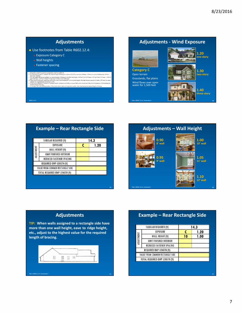
l
l
‐ ‐
l
8232016
37
Adjustments
Use footnotes from Table R602124 Exposure Category C
Wall heights
Fastener spacing
R602124 38
Adjustments ‐Wind Exposure
Tab e R602124 Footnote b
Category C Open terrain
Grasslands flat plains
Wind flows over openwater for 1500 feet
120 one‐story
130 two‐story
140 three‐story
39
Example ndash Rear Rectangle Side
C 143
120
40
Adjustments ndash Wall Height
Tab e R602124 Footnote c
100 10rsquo wall
105 11rsquo wall
110 12rsquo wall
090 8rsquo wall
095 9rsquo wall
Adjustments
TIP When walls assigned to a rectangle side have more than one wall height eave to ridge height etc adjust to the highest value for the required length of bracing
42
Example ndash Rear Rectangle Side
C 143
120 10 100
Tab e R602124 Footnote f 41
7
i i
8232016
43
Adjustments ndash No Interior Finish
R602122 4
140
44
Example ndash Rear Rectangle Side
C 143
120 10 100 NO 100
45
Adjustments ndash Fastener Spacing
R602103 Footnote d
4rdquo fastener spacing
083 OSB or plywood (exterior) when supporting floor(s) above
07 gypsum board (interior)
Virginia nterpretat on
46
Example ndash Rear Rectangle Side
C 143
120 10 100 NO 100 NO 100
Required Length of Bracing Multiply tabular requirements by each adjustment factor
Adjusted length = (tabular value) x (adjustment factor) x (adjustment factor) x (adjustment factor)hellip
Required BWL Length = 143rsquo x 120 x 100 x 100 x 100 = 172rsquo
48
Example ndash Rear Rectangle Side
C 143
120 10 100 NO 100 NO 100
172
47
8
=
l l
8232016
49
Common Rectangle Sides Add Required BWP Length for each side Adjusted length Adjusted length + Adjusted length
LA LA
50
Example ndash Rear Rectangle Side
Repeat for common rectangle side and add required value here
R602124
C 143
120 10 100 NO 100 NO 100
172 0
172
51
Exterior BWP Minimum Length
Based on adjacent opening(s) Adjacent garage opening or
Height of adjacent opening
52
Exterior BWP Minimum Length
R602122
53
Exterior BWP Minimum Length
Tab e R602105
27rdquo minimum
9rsquo tall wall 62rdquo window
54
Exterior BWP Minimum Length
Tab e R602105
36rdquo minimum
9rsquo tall wall 84rdquo door
9
=
=
=
‐ =
=
8232016
55
Braced Wall Panel
R602102
Contributing Length Exterior actual
Interior 05 x actual
ldquoClassicrdquo narrow methods bull PFH 48rdquo
bull PFG CS PF 15 x actual
bull Equivalent products 48rdquo
56
Example ndash Rear Rectangle Side
5rsquo‐9rdquo 11rsquo‐6rdquo 6rsquo20rsquo 7rsquo4rsquo
1 42
REAR RECTANGLE SIDE
3
57
Example ndash Rear Rectangle Wall
575 115
EXTERIOR
4
2725
6
EXTERIOR EXTERIOR EXTERIOR
176
PASS 58
Distribution Rule 1
BWPs located le 12rsquo from house corner
R602126 1
le12rsquo le12rsquo le12rsquo le12rsquo
le12rsquo
59
Distribution Rule 1
BWPs located le 12rsquo from interior rectangle corner
60
Distribution Rule 1
BWPs located le 12rsquo from interior rectangle corner
10
8232016
61
Distribution Rule 1
BWPs located le 12rsquo from interior rectangle corner
62
Distribution Rule 1
BWPs located le 12rsquo from interior rectangle corner
63
Distribution Rule 2
Edge to edge distance between adjacent BWPs le 20rsquo
R602126 2
le20rsquo
64
Distribution Rule 3
Wall gt 8rsquo require at least one BWP
R602126 3
gt8rsquo
gt8rsquo
65
Distribution Rule 3
Wall gt 8rsquo require at least one BWP
Walls le 8rsquo are permitted no BWPs
R602126 4
gt8rsquo
gt8rsquo
le8rsquo
66
Example ndash Rear Rectangle Side
5rsquo‐9rdquo 11rsquo‐6rdquo 6rsquo20rsquo 7rsquo4rsquo
1 42
REAR RECTANGLE SIDE
3
11
68
‐
‐
‐
70
R602127 R602128
8232016
BWPs Adjacent Balloon‐Framed Walls
67
Example ndash Rear Rectangle Side
PASS YES YES YES PASS
Balloon framed walls Two story foyers
Family rooms
BWP locations Each side of two story portion
Each floor
R6021261
69
BWPs Adjacent Balloon‐Framed Walls
R6021261
balloon‐framed
walls
floor floor
Practical Wall Bracing Meets ldquoClassicrdquo
ldquoCLASSICrdquo CARRYOVERS
71
BWP Connections
Refer to R602108
Connections to framing
Connections to roof
72
BWP Support
Refer to R602109
Cantilevered floor restriction
Masonry stem walls
12
‐
‐ ‐
‐ ‐
‐ ‐
‐ ‐
‐ ‐ ‐ ‐ ‐
73
77
8232016
Tying Up Loose Ends
SUM UP
Classic vs Practical R60210 R60212
8 materials 3 materials
4 narrow methods 4 narrow methods
Unlimited size houses Unlimited size houses
Braced wall panels Braced wall panels
Braced wall lines Circumscribed rectangles
All detached homes All detached homes
All townhouses Townhouses in SDC A amp B only
End conditions No end conditions
BWPs 10rsquo from BWL end BWPs 12rsquo from all
houserectangle corners
Greater flexibility Easier application
Nationwide Virginia only 74
75
Publications
Guide to the 2012 IRC Wall Bracing Provisions (APA)
Wind Bracing (Fairfax County)
Prescriptive Design Guide (Simpson Strong Tie)
IRC Wall Bracing Guide for Builders Designers and Plan Reviewers (Foam Sheathing Coalition)
Notes from this class (available on fairfaxcountygov)
Resources
Chuck Bajnai 804 717 6428 bajnaicchesterfieldgov
Brian Foley 703 324 1842 brianfoleyfairfaxcountygov
APA ndash The Engineered Wood Association 253 620 7400 apawoodorg
Simpson Strong Tie (800) 999 5099 strongtiecom
ICC ES 1 800 423 6587 x66546 icc esorg
76
THE END
13

=
=
=
‐ =
=
8232016
55
Braced Wall Panel
R602102
Contributing Length Exterior actual
Interior 05 x actual
ldquoClassicrdquo narrow methods bull PFH 48rdquo
bull PFG CS PF 15 x actual
bull Equivalent products 48rdquo
56
Example ndash Rear Rectangle Side
5rsquo‐9rdquo 11rsquo‐6rdquo 6rsquo20rsquo 7rsquo4rsquo
1 42
REAR RECTANGLE SIDE
3
57
Example ndash Rear Rectangle Wall
575 115
EXTERIOR
4
2725
6
EXTERIOR EXTERIOR EXTERIOR
176
PASS 58
Distribution Rule 1
BWPs located le 12rsquo from house corner
R602126 1
le12rsquo le12rsquo le12rsquo le12rsquo
le12rsquo
59
Distribution Rule 1
BWPs located le 12rsquo from interior rectangle corner
60
Distribution Rule 1
BWPs located le 12rsquo from interior rectangle corner
10
8232016
61
Distribution Rule 1
BWPs located le 12rsquo from interior rectangle corner
62
Distribution Rule 1
BWPs located le 12rsquo from interior rectangle corner
63
Distribution Rule 2
Edge to edge distance between adjacent BWPs le 20rsquo
R602126 2
le20rsquo
64
Distribution Rule 3
Wall gt 8rsquo require at least one BWP
R602126 3
gt8rsquo
gt8rsquo
65
Distribution Rule 3
Wall gt 8rsquo require at least one BWP
Walls le 8rsquo are permitted no BWPs
R602126 4
gt8rsquo
gt8rsquo
le8rsquo
66
Example ndash Rear Rectangle Side
5rsquo‐9rdquo 11rsquo‐6rdquo 6rsquo20rsquo 7rsquo4rsquo
1 42
REAR RECTANGLE SIDE
3
11
68
‐
‐
‐
70
R602127 R602128
8232016
BWPs Adjacent Balloon‐Framed Walls
67
Example ndash Rear Rectangle Side
PASS YES YES YES PASS
Balloon framed walls Two story foyers
Family rooms
BWP locations Each side of two story portion
Each floor
R6021261
69
BWPs Adjacent Balloon‐Framed Walls
R6021261
balloon‐framed
walls
floor floor
Practical Wall Bracing Meets ldquoClassicrdquo
ldquoCLASSICrdquo CARRYOVERS
71
BWP Connections
Refer to R602108
Connections to framing
Connections to roof
72
BWP Support
Refer to R602109
Cantilevered floor restriction
Masonry stem walls
12
‐
‐ ‐
‐ ‐
‐ ‐
‐ ‐
‐ ‐ ‐ ‐ ‐
73
77
8232016
Tying Up Loose Ends
SUM UP
Classic vs Practical R60210 R60212
8 materials 3 materials
4 narrow methods 4 narrow methods
Unlimited size houses Unlimited size houses
Braced wall panels Braced wall panels
Braced wall lines Circumscribed rectangles
All detached homes All detached homes
All townhouses Townhouses in SDC A amp B only
End conditions No end conditions
BWPs 10rsquo from BWL end BWPs 12rsquo from all
houserectangle corners
Greater flexibility Easier application
Nationwide Virginia only 74
75
Publications
Guide to the 2012 IRC Wall Bracing Provisions (APA)
Wind Bracing (Fairfax County)
Prescriptive Design Guide (Simpson Strong Tie)
IRC Wall Bracing Guide for Builders Designers and Plan Reviewers (Foam Sheathing Coalition)
Notes from this class (available on fairfaxcountygov)
Resources
Chuck Bajnai 804 717 6428 bajnaicchesterfieldgov
Brian Foley 703 324 1842 brianfoleyfairfaxcountygov
APA ndash The Engineered Wood Association 253 620 7400 apawoodorg
Simpson Strong Tie (800) 999 5099 strongtiecom
ICC ES 1 800 423 6587 x66546 icc esorg
76
THE END
13

8232016
61
Distribution Rule 1
BWPs located le 12rsquo from interior rectangle corner
62
Distribution Rule 1
BWPs located le 12rsquo from interior rectangle corner
63
Distribution Rule 2
Edge to edge distance between adjacent BWPs le 20rsquo
R602126 2
le20rsquo
64
Distribution Rule 3
Wall gt 8rsquo require at least one BWP
R602126 3
gt8rsquo
gt8rsquo
65
Distribution Rule 3
Wall gt 8rsquo require at least one BWP
Walls le 8rsquo are permitted no BWPs
R602126 4
gt8rsquo
gt8rsquo
le8rsquo
66
Example ndash Rear Rectangle Side
5rsquo‐9rdquo 11rsquo‐6rdquo 6rsquo20rsquo 7rsquo4rsquo
1 42
REAR RECTANGLE SIDE
3
11
68
‐
‐
‐
70
R602127 R602128
8232016
BWPs Adjacent Balloon‐Framed Walls
67
Example ndash Rear Rectangle Side
PASS YES YES YES PASS
Balloon framed walls Two story foyers
Family rooms
BWP locations Each side of two story portion
Each floor
R6021261
69
BWPs Adjacent Balloon‐Framed Walls
R6021261
balloon‐framed
walls
floor floor
Practical Wall Bracing Meets ldquoClassicrdquo
ldquoCLASSICrdquo CARRYOVERS
71
BWP Connections
Refer to R602108
Connections to framing
Connections to roof
72
BWP Support
Refer to R602109
Cantilevered floor restriction
Masonry stem walls
12
‐
‐ ‐
‐ ‐
‐ ‐
‐ ‐
‐ ‐ ‐ ‐ ‐
73
77
8232016
Tying Up Loose Ends
SUM UP
Classic vs Practical R60210 R60212
8 materials 3 materials
4 narrow methods 4 narrow methods
Unlimited size houses Unlimited size houses
Braced wall panels Braced wall panels
Braced wall lines Circumscribed rectangles
All detached homes All detached homes
All townhouses Townhouses in SDC A amp B only
End conditions No end conditions
BWPs 10rsquo from BWL end BWPs 12rsquo from all
houserectangle corners
Greater flexibility Easier application
Nationwide Virginia only 74
75
Publications
Guide to the 2012 IRC Wall Bracing Provisions (APA)
Wind Bracing (Fairfax County)
Prescriptive Design Guide (Simpson Strong Tie)
IRC Wall Bracing Guide for Builders Designers and Plan Reviewers (Foam Sheathing Coalition)
Notes from this class (available on fairfaxcountygov)
Resources
Chuck Bajnai 804 717 6428 bajnaicchesterfieldgov
Brian Foley 703 324 1842 brianfoleyfairfaxcountygov
APA ndash The Engineered Wood Association 253 620 7400 apawoodorg
Simpson Strong Tie (800) 999 5099 strongtiecom
ICC ES 1 800 423 6587 x66546 icc esorg
76
THE END
13