1
Wall Assembly and Material Analysis Graduate Students: Sam North, Cole Poland, Reid Weber Professors: Sergio Palleroni & Huafen Hu Advisor: Ben Deines GBRL Advisor: Santiago Rodriguez THA Project Architect: Nick Hodges Abstract We researched the thought process and reasoning behind the design of wall assemblies from start to finish. We explored the specific reasoning for placement and use of every material in the wall and brought to light where the reasoning came from. The wall assemblies in question are those of an academic building currently under construction on Portland Community College, Cascade Campus designed by Thomas Hacker Associates Architecture (THA). The project consists of two new buildings and a plaza space. The building programs consist of classrooms, open study rooms, a cafeteria and administrative offices. We analyzed the wall type and assembly of one of the buildings. Our focuses for this project was the logic behind material use; testing the thermal properties of materials used; construction methods; and how slight variances in the materials change the overall performance of the wall. Research The wall types in question are rain screens. The rain screen cladding is brick, metal paneling and Resysta. The glazing is a double paned window curtain wall and takes up approximately 30% of the building envelope. Our focus is on the rain screen wall assembly. The basic components of a wall follow: A rain and ultraviolet light control layer, an air control layer, a vapor control layer and a thermal control layer. To best protect the structure vthese layers have been placed on the exterior of the structure (Lstiburek, 2007). Each material has been selected to perform the above mentioned duties efficiently. THA utilized rain screens for this project due to Portland’s wet environment. In this type of climate, rain screens have proven to perform very well in avoiding mildew and mold problems. The rain screen is pressure equalized so capillary action does not occur. Rain screens allow some water to penetrate the cladding but the air gap behind the cladding allows the water to also drain out. The cladding of the building (rain and UV light control) consists of four different materials: Double pane glazing, standard brick masonry unit, honeycomb structured metal paneling and Resysta, a rice husk composite material. Glazing does not control UV light as well as the other materials but it was chosen to naturally light the rooms and allow views outside; brick was chosen because of its historically academic use; and Resysta was chosen as a more personal material to acknowledge the neighborhood. Originally wood was chosen but because of upkeep costs Resysta proved to be a more economical choice that requires less maintenance. There is little research pertaining to the air gap of a rain screen. Code requires a minimum gap of 1” for panel cladding material and 2” for brick to ease construction and allow some spillage of the mortar. The rain screen drains liquid equally if there is a gap of a ¼” and a gap of 4”. Since the air gap is pressure equalized from vents at the top and bottom, there is no barrier from outside environmental conditions. Pressure equalization is used to vent out the moisture accumulating in the wall. While this air gap performs well for ventilation, its thermal properties are unclear, and the air gap width is often arbitrary. There are theories about heat behaving differently depending on gap thickness. If the air gap is too thin conduction can adversely affect the temperature of the air gap and the insulation. If the air gap is too wide convection can adversely affect the insulating properties of the air gap (Al-Houmoud, 2005). Since the air gap is “open” to the exterior air in a rain screen application it does not provide insulation value. THA decided upon their air gap thicknesses based on the code minimum and aesthetic appearance. Since there is no conclusive data on the insulation value of air in the air gap decisions were made predominantly on façade appearances. The brick extends out the most at 8 ¾”, Resysta at 8”, and then the metal panel at 5 ½”. The intention behind this is to show the academic brick the most, the warmth of Resysta and then metal. The minimum air gap for metal panels as stated by the CWCT is 1”, since Resysta is a rebated joint, the NHBC recommends at least 1 ½”, and brick is a minimum of 2” (Williams, 2008). The air gap for Brick, as shown by the drawings is 1 5/8” the air gap of the Resysta assembly is 3 3/8” and the air gap for metal paneling is 7/8”. While all layers act in some way as thermal control some are much better at it than others. The polyiso insulation has the highest thermal insulation value of all the materials in the wall. The air and vapor control layer consists of polyiso insulation and the vapor barrier. The closed cell insulation needs a substrate to attach to which is sheet rock in this case. The sheet rock is attached to the metal stud. A 6” air cavity exists within the stud spacing which could potentially be filled with insulation. THA decided not to fill this air cavity with insulation because of perceptions that it would move the dew point of the wall where it was not wanted. On the interior of the building is sheet rock, cladding and a paint finish. Testing We examined and compared variations in material thickness to test the overall R-values. We tested the thermal properties of six different materials: metal panel, Resysta, polyisocyanurate (polyiso) insulation, sheet rock, vapor barrier and brick (no usable results obtained from the brick assembly, so we used previous data). In the Green Building Research Lab on the PSU Campus we tested the thermal properties of the aforementioned materials in the FOX 314 Thermal Properties Analyzer. In the test, the environment of one side of the material was 20 degrees Celsius and the other side was 40 degrees Celsius. A material’s conductivity was then calculated based on the time required for the material to reach temperature equilibrium. From these tests we found the thermal conductivity in BTU/hour*R (R – Rankine, the thermodynamic absolute temperature scale), which we then applied the specific material’s depth to calculate the resistance value (R-value). From the R-values collected we totaled the overall R-value of the wall. From this data we have also calculated how variances in material thickness can change the total R-value. We found that the material that had the most effect on the overall R-value is the polyiso insulation but there comes a point of diminishing returns and the added insulation becomes uneconomical. By adding one inch to the insulation the R-value would increase from 19 to 24. At an R-value of 19 the wall is 94% efficient in reducing heat flow; at an R-value of 24, efficiency increases slightly to 96%. By increasing the cost of insulation by about 30% there would only be a 2% improvement rating in the efficiency of the overall wall assemblies. However, even with a total wall assembly R-value of 1000, the overall envelope performance would be ineffective due to heat loss through glazing. Discrepancies While ideally air gaps should only exist in the air cavity of the rain screen and between the steel joists imperfections in construction creates small gaps between materials. Some noticeable areas where this occurred are with creases in the vapor barrier and above the L channel that holds the insulation. Al-Houmoud, Mohammad. (March 2005). “Building and Environment.” Elsevier. V. 40 Iss 3. Sciencedirect.com Web. 10 Dec.2013 Lstiburek, Joseph W. (May 2007). “The Perfect Wall.” ASHRAE Journal Print. Ashrae.org Web. 10 Dec.2013 Williams, Austin. “Letting Air in to Keep Rain Out” http://www.thenbs.com 2008. Web. 10 Dec.2013 Material R Value U Value .68 1.47 .508 1.968 1 1 .508 1.968 16.169 .0618 .543 1.84 .17 5.882 19.578 14.19 Air Film Interior Gypsum Board Air Gap Gypsum Board Polyisocyanurate Metal Panel Air Film Exterior Total Material R Value U Value .68 1.47 .508 1.968 1 1 .508 1.968 16.169 .0618 .485 2.059 .17 5.882 19.52 14.409 Air Film Interior Gypsum Board Air Gap Gypsum Board Polyisocyanurate Resysta Air Film Exterior Total Material R Value U Value .68 1.47 .508 1.968 1 1 .508 1.968 16.169 .0618 .8 1.25 .17 5.882 19.835 13.6 Air Film Interior Gypsum Board Air Gap Gypsum Board Polyisocyanurate Brick Air Film Exterior Total Figure 4: Exploded Isometric of Metal Panel Wall System Interior Interior Interior Exterior Exterior Exterior Figure 10: THA Building Methodology including Thermal Properties Testing Figure 7: Metal Panel Wall System Material and Total R Value Figure 1: Exterior Wall Section with Metal Panel Facade Figure 5: Exploded Isometric of Resysta Wall System (Interior to Exterior) Figure 8: Resysta Wall System Material and Total R Value Figure 2: Exterior Wall Section with Resysta Facade Figure 6: Exploded Isometric of Brick Wall System (Interior to Exterior) Figure 9: Brick Wall System Material and Total R Value Figure 3: Exterior Wall Section with Brick Facade Brick Polyiso Rigid Insulation Sheet Rock Sheet Rock Sheet Rock Cladding Support Cladding Support Steel Stud Steel Stud Sheet Rock Sheet Rock Vapor Membrane Metal Furring Vapor Membrane Polyiso Rigid Insulation Polyiso Rigid Insulation Resysta Panel Metal Panel Vapor Profile Vapor Profile Vapor Profile Vapor Membrane Steel Stud Air Film Int. R-Value R-Value R-Value 0 0 0 5 5 5 10 10 10 15 15 15 20 20 20 Air Film Int. Air Film Int. Gypsum Board Gypsum Board Gypsum Board Gypsum Board Gypsum Board Gypsum Board Polyisocyanurate Polyisocyanurate Polyisocyanurate Metal Panel Resysta Panel Brick Air Film Ext. Air Film Ext. Air Film Ext. Air Gap Air Gap Air Gap Define wall assembly types in writing based on aesthetics and performance Preliminary material research Meet with project team to discuss pros and cons, cost, engineering and material choice Project Team: structural, mechanical and electrical engineers; plumbing, HVAC and general contractor *Thermal Properties Testing Meet with product manufacturer Develop and define all necessary details with the schematic assemblies baseline Test assemblies with desired architectural intent (typically at a 1 1/2” = 1’-0” scale) Develop new assemblies for products like Resysta Refine details with design team, contractor and owner in respect to costs, aesthetics, performance and constructibility Refine details with more specificity, focusing on joinery (typically at a 6”=1’-0” scale). Continue to refine details with design team, contractor and owner in respect to costs, aesthetics, performance and contractibility. No changes to wall assembly types Mock-up built to test different connection methods Architect: THA Client: PCC Cascade Campus Public conceptual phase schematic design* design development construction documents construction THA Building Facade Design Methodology

Wall Assembly and Material Analysis

  • Upload
    others

  • View
    1

  • Download
    0

Embed Size (px)

Citation preview

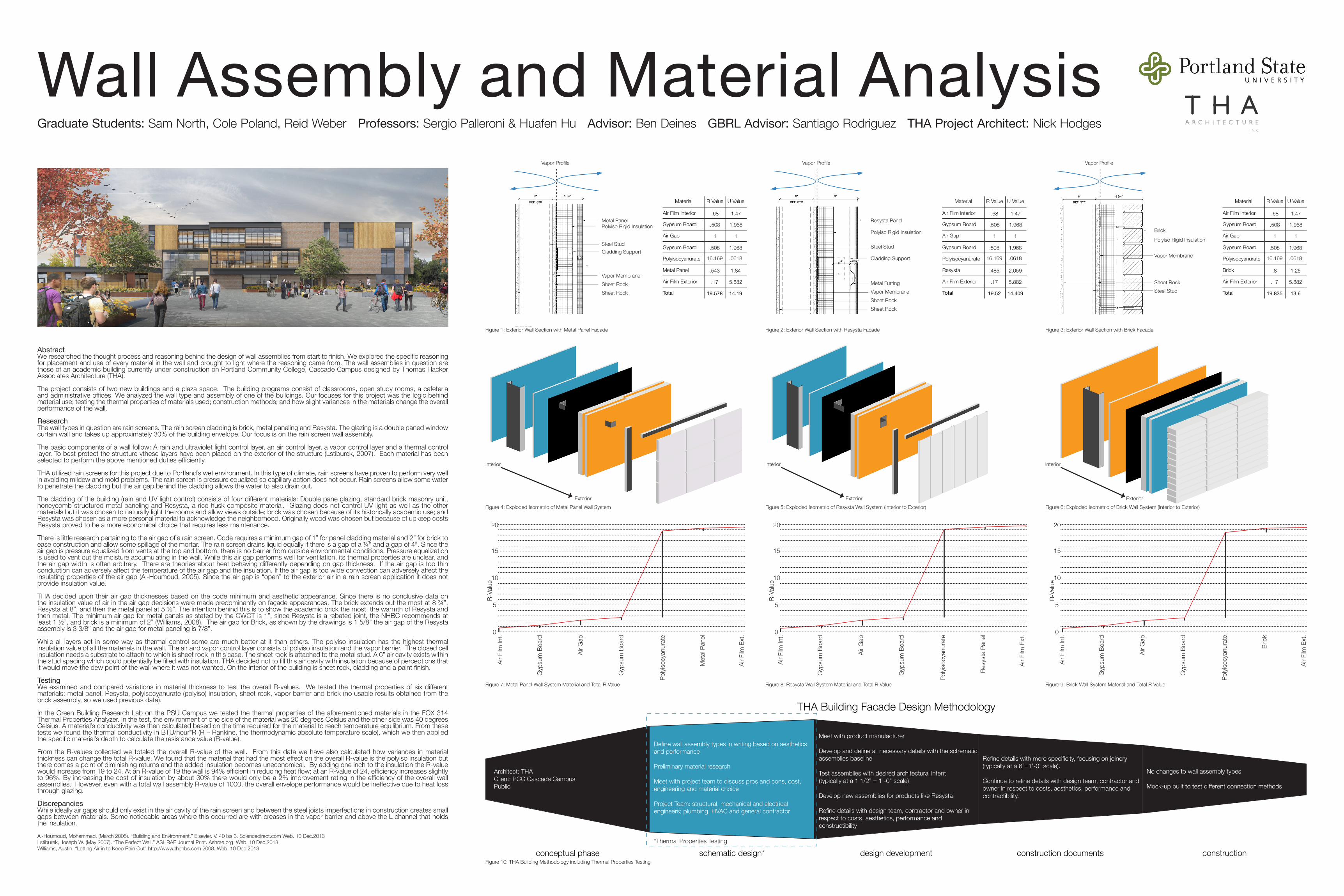
Wall Assembly and Material AnalysisGraduate Students: Sam North, Cole Poland, Reid Weber Professors: Sergio Palleroni & Huafen Hu Advisor: Ben Deines GBRL Advisor: Santiago Rodriguez THA Project Architect: Nick Hodges

AbstractWe researched the thought process and reasoning behind the design of wall assemblies from start to finish. We explored the specific reasoning for placement and use of every material in the wall and brought to light where the reasoning came from. The wall assemblies in question are those of an academic building currently under construction on Portland Community College, Cascade Campus designed by Thomas Hacker Associates Architecture (THA).

The project consists of two new buildings and a plaza space. The building programs consist of classrooms, open study rooms, a cafeteria and administrative offices. We analyzed the wall type and assembly of one of the buildings. Our focuses for this project was the logic behind material use; testing the thermal properties of materials used; construction methods; and how slight variances in the materials change the overall performance of the wall.

ResearchThe wall types in question are rain screens. The rain screen cladding is brick, metal paneling and Resysta. The glazing is a double paned window curtain wall and takes up approximately 30% of the building envelope. Our focus is on the rain screen wall assembly.

The basic components of a wall follow: A rain and ultraviolet light control layer, an air control layer, a vapor control layer and a thermal control layer. To best protect the structure vthese layers have been placed on the exterior of the structure (Lstiburek, 2007). Each material has been selected to perform the above mentioned duties efficiently.

THA utilized rain screens for this project due to Portland’s wet environment. In this type of climate, rain screens have proven to perform very well in avoiding mildew and mold problems. The rain screen is pressure equalized so capillary action does not occur. Rain screens allow some water to penetrate the cladding but the air gap behind the cladding allows the water to also drain out.

The cladding of the building (rain and UV light control) consists of four different materials: Double pane glazing, standard brick masonry unit, honeycomb structured metal paneling and Resysta, a rice husk composite material. Glazing does not control UV light as well as the other materials but it was chosen to naturally light the rooms and allow views outside; brick was chosen because of its historically academic use; and Resysta was chosen as a more personal material to acknowledge the neighborhood. Originally wood was chosen but because of upkeep costs Resysta proved to be a more economical choice that requires less maintenance.

There is little research pertaining to the air gap of a rain screen. Code requires a minimum gap of 1” for panel cladding material and 2” for brick to ease construction and allow some spillage of the mortar. The rain screen drains liquid equally if there is a gap of a ¼” and a gap of 4”. Since the air gap is pressure equalized from vents at the top and bottom, there is no barrier from outside environmental conditions. Pressure equalization is used to vent out the moisture accumulating in the wall. While this air gap performs well for ventilation, its thermal properties are unclear, and the air gap width is often arbitrary. There are theories about heat behaving differently depending on gap thickness. If the air gap is too thin conduction can adversely affect the temperature of the air gap and the insulation. If the air gap is too wide convection can adversely affect the insulating properties of the air gap (Al-Houmoud, 2005). Since the air gap is “open” to the exterior air in a rain screen application it does not provide insulation value.

THA decided upon their air gap thicknesses based on the code minimum and aesthetic appearance. Since there is no conclusive data on the insulation value of air in the air gap decisions were made predominantly on façade appearances. The brick extends out the most at 8 ¾”, Resysta at 8”, and then the metal panel at 5 ½”. The intention behind this is to show the academic brick the most, the warmth of Resysta and then metal. The minimum air gap for metal panels as stated by the CWCT is 1”, since Resysta is a rebated joint, the NHBC recommends at least 1 ½”, and brick is a minimum of 2” (Williams, 2008). The air gap for Brick, as shown by the drawings is 1 5/8” the air gap of the Resysta assembly is 3 3/8” and the air gap for metal paneling is 7/8”.

While all layers act in some way as thermal control some are much better at it than others. The polyiso insulation has the highest thermal insulation value of all the materials in the wall. The air and vapor control layer consists of polyiso insulation and the vapor barrier. The closed cell insulation needs a substrate to attach to which is sheet rock in this case. The sheet rock is attached to the metal stud. A 6” air cavity exists within the stud spacing which could potentially be filled with insulation. THA decided not to fill this air cavity with insulation because of perceptions that it would move the dew point of the wall where it was not wanted. On the interior of the building is sheet rock, cladding and a paint finish.

TestingWe examined and compared variations in material thickness to test the overall R-values. We tested the thermal properties of six different materials: metal panel, Resysta, polyisocyanurate (polyiso) insulation, sheet rock, vapor barrier and brick (no usable results obtained from the brick assembly, so we used previous data).

In the Green Building Research Lab on the PSU Campus we tested the thermal properties of the aforementioned materials in the FOX 314 Thermal Properties Analyzer. In the test, the environment of one side of the material was 20 degrees Celsius and the other side was 40 degrees Celsius. A material’s conductivity was then calculated based on the time required for the material to reach temperature equilibrium. From these tests we found the thermal conductivity in BTU/hour*R (R – Rankine, the thermodynamic absolute temperature scale), which we then applied the specific material’s depth to calculate the resistance value (R-value).

From the R-values collected we totaled the overall R-value of the wall. From this data we have also calculated how variances in material thickness can change the total R-value. We found that the material that had the most effect on the overall R-value is the polyiso insulation but there comes a point of diminishing returns and the added insulation becomes uneconomical. By adding one inch to the insulation the R-value would increase from 19 to 24. At an R-value of 19 the wall is 94% efficient in reducing heat flow; at an R-value of 24, efficiency increases slightly to 96%. By increasing the cost of insulation by about 30% there would only be a 2% improvement rating in the efficiency of the overall wall assemblies. However, even with a total wall assembly R-value of 1000, the overall envelope performance would be ineffective due to heat loss through glazing.

DiscrepanciesWhile ideally air gaps should only exist in the air cavity of the rain screen and between the steel joists imperfections in construction creates small gaps between materials. Some noticeable areas where this occurred are with creases in the vapor barrier and above the L channel that holds the insulation.

Al-Houmoud, Mohammad. (March 2005). “Building and Environment.” Elsevier. V. 40 Iss 3. Sciencedirect.com Web. 10 Dec.2013Lstiburek, Joseph W. (May 2007). “The Perfect Wall.” ASHRAE Journal Print. Ashrae.org Web. 10 Dec.2013Williams, Austin. “Letting Air in to Keep Rain Out” http://www.thenbs.com 2008. Web. 10 Dec.2013

Material R Value U Value

.68 1.47

.508 1.968

1 1

.508 1.968

16.169 .0618

.543 1.84

.17 5.882

19.578 14.19

Air Film Interior

Gypsum Board

Air Gap

Gypsum Board

Polyisocyanurate

Metal Panel

Air Film Exterior

Total

Material R Value U Value

.68 1.47

.508 1.968

1 1

.508 1.968

16.169 .0618

.485 2.059

.17 5.882

19.52 14.409

Air Film Interior

Gypsum Board

Air Gap

Gypsum Board

Polyisocyanurate

Resysta

Air Film Exterior

Total

Material R Value U Value

.68 1.47

.508 1.968

1 1

.508 1.968

16.169 .0618

.8 1.25

.17 5.882

19.835 13.6

Air Film Interior

Gypsum Board

Air Gap

Gypsum Board

Polyisocyanurate

Brick

Air Film Exterior

Total

Figure 4: Exploded Isometric of Metal Panel Wall System

InteriorInteriorInterior

ExteriorExteriorExterior

Figure 10: THA Building Methodology including Thermal Properties Testing

Figure 7: Metal Panel Wall System Material and Total R Value

Figure 1: Exterior Wall Section with Metal Panel Facade

Figure 5: Exploded Isometric of Resysta Wall System (Interior to Exterior)

Figure 8: Resysta Wall System Material and Total R Value

Figure 2: Exterior Wall Section with Resysta Facade

Figure 6: Exploded Isometric of Brick Wall System (Interior to Exterior)

Figure 9: Brick Wall System Material and Total R Value

Figure 3: Exterior Wall Section with Brick Facade

Brick

Polyiso Rigid Insulation

Sheet Rock

Sheet Rock

Sheet Rock

Cladding SupportCladding Support

Steel StudSteel Stud

Sheet Rock

Sheet Rock Vapor MembraneMetal Furring

Vapor Membrane

Polyiso Rigid InsulationPolyiso Rigid Insulation

Resysta PanelMetal Panel

Vapor Profile Vapor Profile Vapor Profile

Vapor Membrane

Steel Stud

Air F

ilm In

t.R-

Valu

e

R-Va

lue

R-Va

lue

0 0 0

5 5 5

10 10 10

15 15 15

20 20 20

Air F

ilm In

t.

Air F

ilm In

t.

Gyp

sum

Boa

rd

Gyp

sum

Boa

rd

Gyp

sum

Boa

rd

Gyp

sum

Boa

rd

Gyp

sum

Boa

rd

Gyp

sum

Boa

rd

Polyi

socy

anur

ate

Polyi

socy

anur

ate

Polyi

socy

anur

ate

Met

al Pa

nel

Resy

sta

Pane

l

Brick

Air F

ilm E

xt.

Air F

ilm E

xt.

Air F

ilm E

xt.

Air G

ap

Air G

ap

Air G

ap

Define wall assembly types in writing based on aesthetics and performance

Preliminary material research

Meet with project team to discuss pros and cons, cost, engineering and material choice

Project Team: structural, mechanical and electrical engineers; plumbing, HVAC and general contractor

*Thermal Properties Testing

Meet with product manufacturer

Develop and define all necessary details with the schematic assemblies baseline

Test assemblies with desired architectural intent (typically at a 1 1/2” = 1’-0” scale)

Develop new assemblies for products like Resysta

Refine details with design team, contractor and owner in respect to costs, aesthetics, performance and constructibility

Refine details with more specificity, focusing on joinery (typically at a 6”=1’-0” scale).

Continue to refine details with design team, contractor and owner in respect to costs, aesthetics, performance and contractibility.

No changes to wall assembly types

Mock-up built to test different connection methods

Architect: THAClient: PCC Cascade CampusPublic

conceptual phase schematic design* design development construction documents construction

THA Building Facade Design Methodology