Embed Size (px)
Citation preview

The WalkAide® System
Clinician Manual
INDEPENDENCEone step at a time
Caution: USA Federal Law restricts this device to sale by or on the order of a physician.
LM06-R6
© 2013 Innovative Neurotronics. All rights reserved. All trademarks and registered trademarksare the property of their respective holders. No part of this manual may be reproduced in any form without the written consent of Innovative Neurotronics Incorporated. Information in this manual is for the use of qualified clinicians only.
EC REP
Medical Device & QA Services76, Stockport RoadTimperley, CheshireWA15 7SNUnited KingdomTel: 44 161 870 6751e-mail: [email protected]
0086
1.0 Introduction 21.1 Indications of Use 21.2 Contraindications 31.3 Warnings About FES 31.4 WalkAideSpecificWarnings 41.5 Precautions 51.6 Regulatory Information 51.7 Adverse Reactions 61.8 Cautions 61.9 Glossary 6
2.0 Equipment 102.1 Clinician Kit 102.2 Patient Kit 112.3 Demo Kit 112.4 WalkAide/WalkLink Controls, Indicators & Alarms 122.5 WalkAide Bi-Flex Cuff 132.6 Electrode Replacement 142.7 WalkAide Cuff Disposable Liner 152.8 SymbolsandDefinitions 16
3.0 WalkAnalyst Software 163.1 Installation 163.2 WalkAnalyst Upgrades 173.3 Administration 173.4 Changing Clinical Preferences 183.5 Backup 18
4.0 WalkLinkConfigurationandBluetoothPairing 194.1 Configuringinitialset-upprocess(Pairing) 19
5.0 FittingProcess 205.1 Pre-screening with the Peripheral Nerve Stimulator 205.2 Electrode Placements and System Preparations 225.3 Fitting a New Patient 255.4 Fitting a Returning Patient 255.5 Programming Options 26
5.5.1 Rapid+ Program 265.5.2 Standard Program 295.5.3 Adjustment 325.5.4 Recover Program 335.5.5 Transfer Program 33
5.6 Exercise Mode Settings 345.7 Wearing Schedule 355.8 Usage Log 36
6.0 Evaluation&Reporting 37
7.0 UseandCareoftheWalkAideandAccessories 397.1 Care and Use of WalkAide Electrodes 39
8.0 ClinicalTroubleshooting 408.1 Electrode Placement Best Practice 408.2 Manual Adjustment of the Stimulation Settings 418.3 Graph Analysis 468.4 Follow-Up and Re-Optimization 47
9.0 TechnicalTroubleshooting 499.1 WalkAide Troubleshooting 499.2 WalkLink Troubleshooting 519.3 Alternate Pairing Method 529.4 Bluetooth USB Troubleshooting 52
10.0 WalkAide User Manual 53
11.0 TechnicalInformation 54
12.0 Contact Information 55
2 3
1.0 Introduction
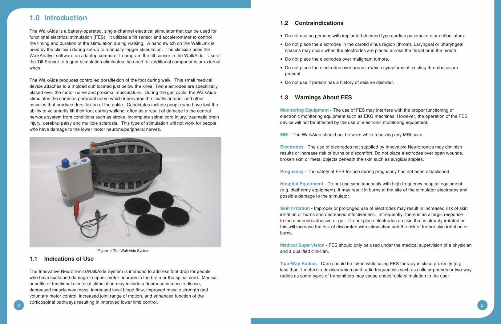
The WalkAide is a battery-operated, single-channel electrical stimulator that can be used for functionalelectricalstimulation(FES).Itutilizesatiltsensorandaccelerometertocontrolthe timing and duration of the stimulation during walking. A hand switch on the WalkLink is used by the clinician during set-up to manually trigger stimulation. The clinician uses the WalkAnalyst software on a laptop computer to program the tilt sensor in the WalkAide. Use of the Tilt Sensor to trigger stimulation eliminates the need for additional components or external wires.
TheWalkAideproducescontrolleddorsiflexionofthefootduringwalk.Thissmallmedicaldeviceattachestoamoldedcufflocatedjustbelowtheknee.Twoelectrodesarespecificallyplaced over the motor nerve and proximal musculature. During the gait cycle, the WalkAide stimulates the common peroneal nerve which innervates the tibialis anterior and other musclesthatproducedorsiflexionoftheankle.Candidatesincludepeoplewhohavelosttheability to voluntarily lift their foot during walking, often as a result of damage to the central nervous system from conditions such as stroke, incomplete spinal cord injury, traumatic brain injury, cerebral palsy and multiple sclerosis. This type of stimulation will not work for people who have damage to the lower motor neurons/peripheral nerves.
1.1 Indications of Use
The Innovative NeurotronicsWalkAide System is intended to address foot drop for people who have sustained damage to upper motor neurons in the brain or the spinal cord. Medical benefitsoffunctionalelectricalstimulationmayincludeadecreaseinmuscledisuse,decreasedmuscleweakness,increasedlocalbloodflow,improvedmusclestrengthandvoluntary motor control, increased joint range of motion, and enhanced function of the corticospinal pathways resulting in improved lower limb control.
1.2 Contraindications
Donotuseonpersonswithimplanteddemandtypecardiacpacemakersordefibrillators. •
Donotplacetheelectrodesinthecarotidsinusregion(throat).Laryngealorpharyngeal •spasms may occur when the electrodes are placed across the throat or in the mouth.
Do not place the electrodes over malignant tumors. •
Do not place the electrodes over areas in which symptoms of existing thrombosis are •present.
Do not use if person has a history of seizure disorder. •
1.3 WarningsAboutFES
MonitoringEquipment - The use of FES may interfere with the proper functioning of electronic monitoring equipment such as EKG machines. However, the operation of the FES device will not be affected by the use of electronic monitoring equipment.
MRI - The WalkAide should not be worn while receiving any MRI scan.
Electrodes - The use of electrodes not supplied by Innovative Neurotronics may diminish results or increase risk of burns or discomfort. Do not place electrodes over open wounds, broken skin or metal objects beneath the skin such as surgical staples.
Pregnancy - The safety of FES for use during pregnancy has not been established.
Hospital Equipment - Do not use simultaneously with high frequency hospital equipment (e.g.diathermyequipment).Itmayresultinburnsatthesiteofthestimulatorelectrodesandpossible damage to the stimulator.
Skin Irritation - Improper or prolonged use of electrodes may result in increased risk of skin irritation or burns and decreased effectiveness. Infrequently, there is an allergic response to the electrode adhesive or gel. Do not place electrodes on skin that is already irritated as this will increase the risk of discomfort with stimulation and the risk of further skin irritation or burns.
Medical Supervision - FES should only be used under the medical supervision of a physician andaqualifiedclinician.
Two-Way Radios-CareshouldbetakenwhileusingFEStherapyincloseproximity(e.g.lessthan1meter)todeviceswhichemitradiofrequenciessuchascellularphonesortwo-wayradios as some types of transmitters may cause undesirable stimulation to the user.
Figure 1: The WalkAide System
4 5
Defibrillator-ExternaldefibrillationofapersonwearingaFESdevicecandamagethedevice or injure the user even when the device is turned off. Under some circumstances there mayberiskofburnsundertheelectrodesitesduringdefibrillation.Toeliminateanyrisk,theFESelectrodesshouldberemovedbeforedefibrillationpaddlesareapplied.
ChronicStimulation - Effects of long term chronic stimulation are unknown in this particular application.
1.4 WalkAideSpecificWarnings
Walking - Care should be taken when using the WalkAide for people who experience dizzinessorhavedifficultymaintainingbalance.TheWalkAideisnotdesignedtopreventfalling. Assess user’s condition for inability to walk or balance.
Electrodes - The user should not relocate the position of the electrodes within the cuff. Do not use the WalkAide without electrodes.
Placement - Never use the WalkAide on any area of the body other than the leg.
Stimulation - Stop using the WalkAide if stimulation does not come on at the appropriate time when walking and/or there is a change in the sensation perceived while the stimulation is on.
Environment-WalkAideandWalkLinkarenotintendedforusewithinflammableenvironments such as oxygen and anesthetics.
Impact - Care should be taken to prevent excessive impact to the WalkAide Control Module. This includes standing or kneeling on the unit, or impact from any hard surfaces.
WalkLink
1. FCC Part 15 notice:
This device complies with Part 15 of the FCC Rules. Operation is subject to the following twoconditions:(1)Thisdevicemaynotcauseharmfulinterference,and(2)thisdevicemust accept any interference received, including interference that may cause undesired operation.
2. FCC Radiation Exposure Statement for Portable Devices
This equipment complies with FCC radiation exposure limits set forth for an uncontrolled environment. This equipment is in direct contact with the body of the user under normal operating conditions. This transmitter must not be co-located or operating in conjunction with any other antenna or transmitter.
3.Theuseriscautionedthatchangesormodificationsnotexpresslyapprovedbythepartyresponsible for compliance could void the user’s authority to operate the equipment.
1.5 Precautions
Heart Disease - Use caution in applying electrical stimulation to persons suspected of having heart disease. More clinical data is needed to show that such persons will not experience adverse results.
Sensory Deprivation - Use caution when placing electrodes on areas of the skin with reduced response to normal sensory stimuli, due to the risk of skin burns.
Children - FES devices should be kept out of the reach of children.
Epilepsy - Use caution in applying electrical stimulation to persons suspected of having epilepsy. More clinical data is needed to show that such a person will not experience adverse events.
RecentSurgery - Do not use FES following recent surgery where muscle contraction may disrupt the healing process.
Electrodes - Do not use lotion or oil in the area that the electrodes make contact with the skin. Stimulation may not be effective.
ProperUse-ThesafetyandefficacyofFESdependsontheproperuseandhandlingofthe FES system. Improper use of the device or electrodes can result in injury to the user. Regularlycheckaccessoriesforwearandreplaceasneeded.Electrodesshouldbefirmlysecured to the skin. Never use the WalkAide if it appears to be malfunctioning. If there isachangeinthewayitusuallyworks(i.e.changeinsensation,surgingofstimulation,intermittentstimulation)donotusetheWalkAideandcontactInnovativeNeurotronicsimmediately.
OperatingEquipment - The stimulator should not be used while operating potentially dangerous equipment such as automobiles, power lawn mowers or large machinery. Abrupt changes in stimulation level could create a hazard.
Sleeping - The WalkAide should not be worn or used while sleeping or bathing.
Heat and Cold - The use of heat or cold producing devices such as electric blankets, heating pads or ice packs may affect the electrodes or the person’s circulation and increase the risk of injury. A medical doctor and clinician should be consulted before using with FES.
Caution - Do not plug foot sensor into any electrical socket other than WalkAide.
Caution - Do not unplug foot sensor while sensor is in the shoe.
1.6 RegulatoryInformation
FDA is the regulatory agency that governs the process of testing and approval of medical devices.TheWalkAidehasbeenclassifiedasaClassIImedicaldevice,requiringFDA510(k)approvalofdevicesafetyandtheeffectivenessofthedevicepriortomarketing.
6 7
InnovativeNeurotronicssubmittedthe510(k)toFDAwhichcontainedextensivetestinganddesigndata,andsuccessfullyreceived510(k)approvalon09/21/05.
1.7 Adverse Reactions
Skin irritation and burns beneath the electrodes have been reported with the use of nerve stimulators. Do not leave the electrodes in place for long periods of time without checking or cleaning the skin underneath them. It is normal to observe somewhat reddened areas under the electrodes immediately following use; however, the redness should disappear within an hour. Signs of irritation are maintained redness, small pimple-like lesions or blisters. DO NOT continue stimulation over irritated skin. Notify the medical doctor if these conditions persist and and discontinue use of the WalkAide until the problem is resolved.
1.8 Cautions
Functional electrical stimulation is the process of using electrical stimulation to produce a muscle contraction during a dynamic activity, such as walking. Basic rules of FES use include:
1. ALWAYSusetheWalkAideunderthespecificinstructionofanexperiencedclinician.
2. NEVER use the WalkAide in a situation where an unexpected or unusual stimulus may occur, such as driving or operating motorized equipment.
3. DO NOT use the WalkAide if the equipment is not operating properly.
4. NEVER use the WalkAide unit with frayed or broken leads.
5. ALWAYS handle the unit carefully…do not expose the unit to water, excessive heat or vibration.
6. DO NOT place electrodes anywhere other than on one leg below the knee, as instructed by clinician.
7. AVOID excessive impact, dropping or kneeling on the WalkAide unit. Although robustly designed, damage may occur that could cause the unit to malfunction.
8. The WalkAide should ONLY be used with approved accessories and electrodes.
9. DO NOT open the unit other than to replace the battery. The WalkAide has no user or clinician serviceable parts inside the control module enclosure.
10. TURN OFF the unit if sitting for an extended period of time.
1.9 Glossary
AutosetWalkAideParametersThis calculation process adjusts the threshold settings to more closely match the individual data collected.
AudibleBeepOptional Biofeedback Feature. Audible signal can be activated to indicate when the stimulus is on. Hold the middle button down and turn the WalkAide on by turning the blue knob.
CollectWalkingDataCollects patient walking data from the Heel Sensor, Hand Switch and/or Tilt Sensor during: (1)initialdatacollectionprocedures,(2)programmedwalkingtrialsineitherTiltorHeelmode,and(3)follow-upwalkingtrialsforconfirmationofeffectivewalkingprogramsorre-optimization.
CollectedLogsSaved Usage Logs listed as date and time stamped events.
CommentsAllowsthecliniciantodocumentclinicalnotesintheuser’selectronicfile.
Control TimesAdjustthedurationofthestimulation(MinandMaxTimes);pausingofthestimulation(WaitTime);andinitiationandterminationofthestimulation(RampOn,RampOff).
Bi-FlexCuffPretibial shell that attaches to the leg and is used to hold the electrodes and the WalkAide control module in the correct position.
DefaultSettingsA pre-determined set of parameters that must always be sent to the WalkAide before collection of initial walking data for a new user.
DeleteDeletes entire walking trial.
ExerciseModeAllowstheusertorepeatedlystimulatethelowerlegwhiletheuserissitting(NOTwalking)fora set period of time as determined by the clinician.
ExerciseSettingsAllows the clinician to adjust the ON time, OFF time and duration of the Exercise Mode function for the individual user.
FilterParameterA calculation function that attempts to smooth ‘noisy’ data; and can also delay or accelerate the onset of the stimulation. Filter parameters need to be applied prior to collecting walking data.
Functional Electrical Stimulation (FES)A method of applying a low level of electrical impulses to the motor nerve to activate dysfunctional muscles and produce intentional and useful movement.
HandSwitchA function of the WalkLink whereby pressing the STIM button on the WalkLink sends a command to the WalkAide unit to provide stimulation when the WalkAide is programmed in Hand Mode.
8 9
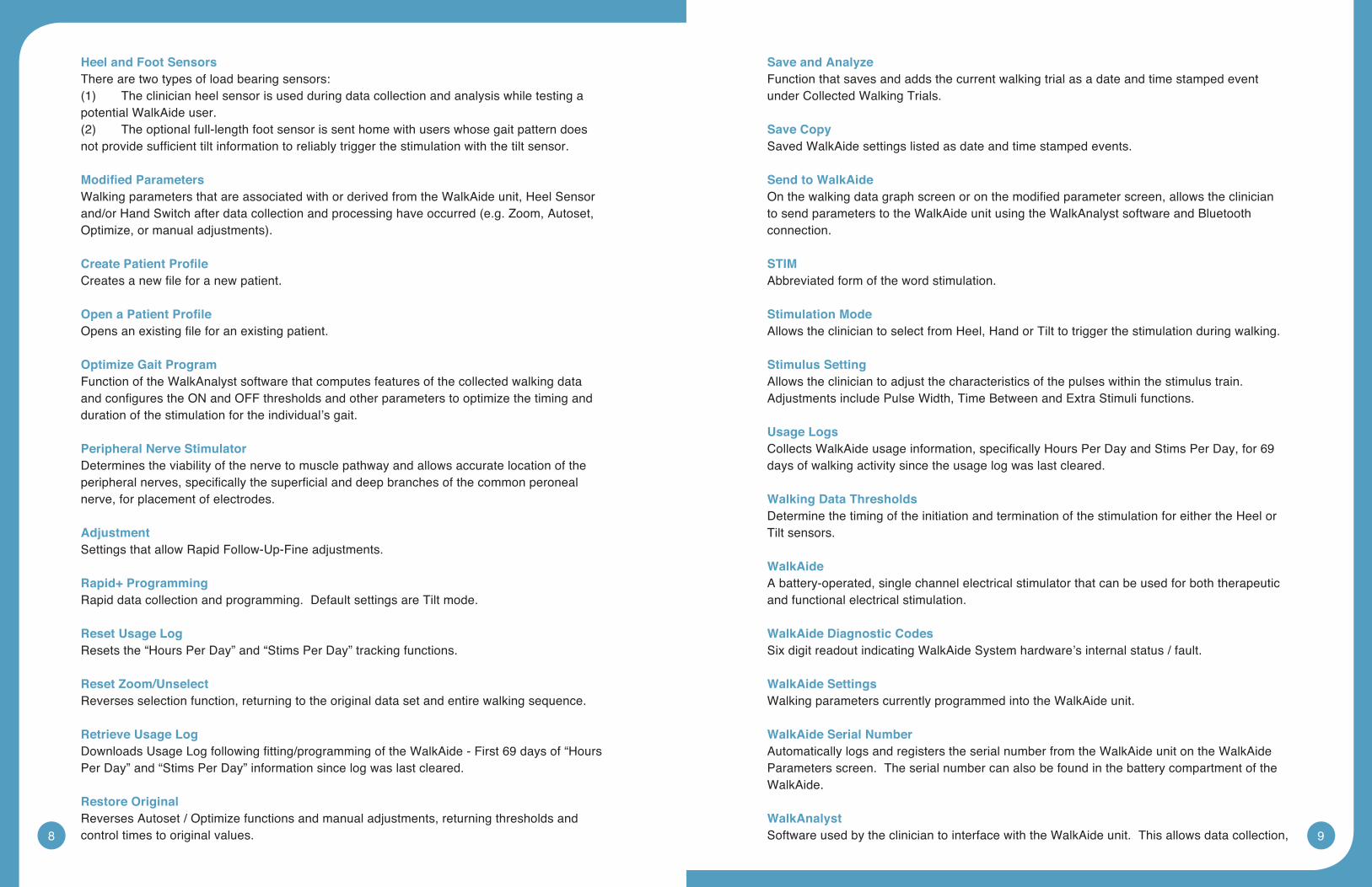
Heel and Foot SensorsThere are two types of load bearing sensors:(1) Theclinicianheelsensorisusedduringdatacollectionandanalysiswhiletestingapotential WalkAide user.(2) Theoptionalfull-lengthfootsensorissenthomewithuserswhosegaitpatterndoesnotprovidesufficienttiltinformationtoreliablytriggerthestimulationwiththetiltsensor.
ModifiedParametersWalking parameters that are associated with or derived from the WalkAide unit, Heel Sensor and/orHandSwitchafterdatacollectionandprocessinghaveoccurred(e.g.Zoom,Autoset,Optimize,ormanualadjustments).
CreatePatientProfileCreatesanewfileforanewpatient.
OpenaPatientProfileOpensanexistingfileforanexistingpatient.
OptimizeGaitProgramFunction of the WalkAnalyst software that computes features of the collected walking data andconfigurestheONandOFFthresholdsandotherparameterstooptimizethetimingandduration of the stimulation for the individual’s gait.
PeripheralNerveStimulatorDetermines the viability of the nerve to muscle pathway and allows accurate location of the peripheralnerves,specificallythesuperficialanddeepbranchesofthecommonperonealnerve, for placement of electrodes.
AdjustmentSettings that allow Rapid Follow-Up-Fine adjustments.
Rapid+ProgrammingRapid data collection and programming. Default settings are Tilt mode.
ResetUsageLogResets the “Hours Per Day” and “Stims Per Day” tracking functions.
Reset Zoom/UnselectReverses selection function, returning to the original data set and entire walking sequence.
RetrieveUsageLogDownloadsUsageLogfollowingfitting/programmingoftheWalkAide-First69daysof“HoursPer Day” and “Stims Per Day” information since log was last cleared.
RestoreOriginalReverses Autoset / Optimize functions and manual adjustments, returning thresholds and control times to original values.
Save and AnalyzeFunction that saves and adds the current walking trial as a date and time stamped event under Collected Walking Trials.
Save CopySaved WalkAide settings listed as date and time stamped events.
Send to WalkAideOnthewalkingdatagraphscreenoronthemodifiedparameterscreen,allowstheclinicianto send parameters to the WalkAide unit using the WalkAnalyst software and Bluetooth connection.
STIMAbbreviated form of the word stimulation.
Stimulation ModeAllows the clinician to select from Heel, Hand or Tilt to trigger the stimulation during walking.
StimulusSettingAllows the clinician to adjust the characteristics of the pulses within the stimulus train. Adjustments include Pulse Width, Time Between and Extra Stimuli functions.
UsageLogsCollectsWalkAideusageinformation,specificallyHoursPerDayandStimsPerDay,for69days of walking activity since the usage log was last cleared.
WalkingDataThresholdsDetermine the timing of the initiation and termination of the stimulation for either the Heel or Tilt sensors.
WalkAideA battery-operated, single channel electrical stimulator that can be used for both therapeutic and functional electrical stimulation.
WalkAideDiagnosticCodesSix digit readout indicating WalkAide System hardware’s internal status / fault.
WalkAideSettingsWalking parameters currently programmed into the WalkAide unit.
WalkAide Serial NumberAutomatically logs and registers the serial number from the WalkAide unit on the WalkAide Parameters screen. The serial number can also be found in the battery compartment of the WalkAide.
WalkAnalystSoftware used by the clinician to interface with the WalkAide unit. This allows data collection,
10 11
analysisandparametermodificationinordertocorrectlytimetheappliedstimulationtotheuser.
WalkLinkProvides a wireless connection between the WalkAide and a computer, and also allows manual stimulation during walking trials via the Hand Switch.
Zoom/SelectAllowsthecliniciantofocusonspecificdatabyhighlightingasequenceofconsecutivestepswith the stylus or mouse.
2.0 Equipment
2.1 Clinician Kit
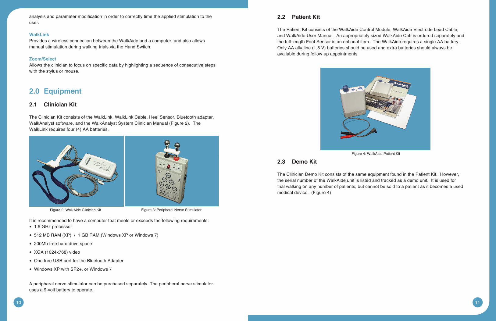
The Clinician Kit consists of the WalkLink, WalkLink Cable, Heel Sensor, Bluetooth adapter, WalkAnalystsoftware,andtheWalkAnalystSystemClinicianManual(Figure2).TheWalkLinkrequiresfour(4)AAbatteries.
It is recommended to have a computer that meets or exceeds the following requirements:1.5 GHz processor •
512MBRAM(XP)/1GBRAM(WindowsXPorWindows7) •
200Mb free hard drive space •
XGA(1024x768)video •
One free USB port for the Bluetooth Adapter •
WindowsXPwithSP2+,orWindows7 •
A peripheral nerve stimulator can be purchased separately. The peripheral nerve stimulator uses a 9-volt battery to operate.
2.2 PatientKit
The Patient Kit consists of the WalkAide Control Module, WalkAide Electrode Lead Cable, and WalkAide User Manual. An appropriately sized WalkAide Cuff is ordered separately and the full-length Foot Sensor is an optional item. The WalkAide requires a single AA battery. OnlyAAalkaline(1.5V)batteriesshouldbeusedandextrabatteriesshouldalwaysbeavailable during follow-up appointments.
2.3 Demo Kit
The Clinician Demo Kit consists of the same equipment found in the Patient Kit. However, the serial number of the WalkAide unit is listed and tracked as a demo unit. It is used for trial walking on any number of patients, but cannot be sold to a patient as it becomes a used medicaldevice.(Figure4)
Figure 2: WalkAide Clinician Kit Figure 3: Peripheral Nerve Stimulator
Figure 4: WalkAide Patient Kit
12 13
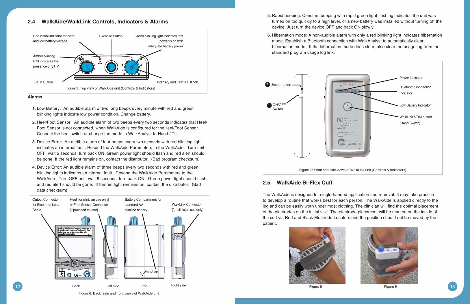
2.4 WalkAide/WalkLink Controls, Indicators & Alarms
Alarms:
1. Low Battery: An audible alarm of two long beeps every minute with red and green blinking lights indicate low power condition. Change battery.
2. Heel/Foot Sensor: An audible alarm of two beeps every two seconds indicates that Heel/FootSensorisnotconnected,whenWalkAideisconfiguredfortheHeel/FootSensor.Connect the heel switch or change the mode in WalkAnalyst to Hand / Tilt.
3. Device Error: An audible alarm of four beeps every two seconds with red blinking light indicates an internal fault. Resend the WalkAide Parameters to the WalkAide. Turn unit OFF,wait5seconds,turnbackON.Greenpowerlightshouldflashandredalertshouldbegone.Iftheredlightremainson,contactthedistributor.(Badprogramchecksum)
4. Device Error: An audible alarm of three beeps every two seconds with red and green blinking lights indicates an internal fault. Resend the WalkAide Parameters to the WalkAide.TurnOFFunit,wait5seconds,turnbackON.Greenpowerlightshouldflashandredalertshouldbegone.Iftheredlightremainson,contactthedistributor.(Baddatachecksum)
5.Rapidbeeping:Constantbeepingwithrapidgreenlightflashingindicatestheunitwasturned on too quickly to a high level, or a new battery was installed without turning off the device. Just turn the device OFF and back ON slowly.
6. Hibernation mode: A non-audible alarm with only a red blinking light indicates hibernation mode. Establish a Bluetooth connection with WalkAnalyst to automatically clear hibernation mode. If the hibernation mode does clear, also clear the usage log from the standard program usage log link.
2.5 WalkAideBi-FlexCuff
The WalkAide is designed for single-handed application and removal. It may take practice to develop a routine that works best for each person. The WalkAide is applied directly to the legandcanbeeasilywornundermostclothing.Theclinicianwillfindtheoptimalplacementof the electrodes on the initial visit. The electrode placement will be marked on the inside of the cuff via Red and Black Electrode Locators and the position should not be moved by the patient.
Power Indicator
WalkLink STIM button
(HandSwitch)
Low Battery Indicator
Bluetooth Connection
Indicator
Unpair button
ON/OFF Switch
1
2
Red visual indicator for error and low battery voltage
Green blinking light indicates that power is on with
adequate battery power
Amber blinking light indicates the presence of STIM
STIM Button Intensity and ON/OFF Knob
Exercise Button
Figure 8 Figure 9
Figure5:TopviewofWalkAideunit(Controls&Indicators)
Output Connector
for Electrode Lead
Cable
WalkLink Connector
[for clinician use only]
Battery Compartment for
standard AA
alkaline battery
Heel [for clinician use only]
or Foot Sensor Connector
[if provided to user]
Back Left side Right sideFront
Figure 6: Back, side and front views of WalkAide unit
Figure7:FrontandsideviewsofWalkLinkunit(Controls&Indicators)
14 15
Thecuffmustbepositionedonthelegcorrectlytoachieveeffectiveandefficientstimulation.Use the Orange visual indicator as a reference for accurate placement of the cuff. Only use thelatchtosecureandremovetheWalkAide.TheVelcrostrapisadjustedtoanoptimallevelby your clinician at the initial visit and should not be altered.
For proper skincare and maximum effectiveness, the electrodes should be replaced every 1 to 2 weeks or immediately upon excessive visible wear. When replacing the electrodes, be sure NOT to alter the placement of the Black and Red Electrode Locators.
2.6 Electrode Replacement
Disconnect the black and red leads between the WalkAide and the electrodes then remove the electrodes from the Electrode Locator. Place new electrodes on the Electrode Locators and feed the leads through the holes toward the outside of the cuff. The BLACK lead is connected to the electrode on the BLACK Electrode Locator. The RED lead is connected to the electrode on the RED Electrode Locator. Feed the excess wires in the strap pouch as indicated in the image below.
WashingInstructions:TowashtheWalkAideCufffabricliner;firstremovetheelectrodes,andthen remove the liner from the cuff. Do NOT remove the Black and Red Electrode Locators. Make sure to Hand Wash, do not use bleach and line dry only.
Sizing Note for Clinicians: To achieve the minimum size, the strap can be folded multiple timesandsecuredusingthedouble-sidedVelcroprovided.
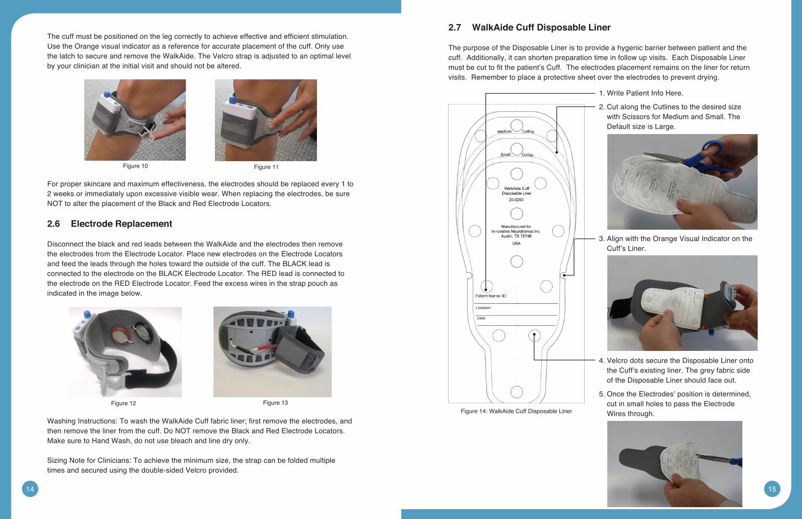
2.7 WalkAide Cuff Disposable Liner
The purpose of the Disposable Liner is to provide a hygenic barrier between patient and the cuff. Additionally, it can shorten preparation time in follow up visits. Each Disposable Liner mustbecuttofitthepatient’sCuff.Theelectrodesplacementremainsonthelinerforreturnvisits. Remember to place a protective sheet over the electrodes to prevent drying.
Figure 10 Figure 11
Figure 12 Figure 13
1. Write Patient Info Here.
2. Cut along the Cutlines to the desired size with Scissors for Medium and Small. The Default size is Large.
3.AlignwiththeOrangeVisualIndicatorontheCuff’s Liner.
4.VelcrodotssecuretheDisposableLinerontothe Cuff’s existing liner. The grey fabric side of the Disposable Liner should face out.
5. Once the Electrodes’ position is determined, cut in small holes to pass the Electrode Wires through.Figure 14: WalkAide Cuff Disposable Liner
16 17
2.8 SymbolsandDefinitions
MeaningofSymbols
Attention, consult accompanying documents
Indicates connector location for Clinician Heel Sensor and optional Patient Foot Sensor
Type BF EquipmentIndicates input/output connector location for WalkLink
Indicates Error Signal Indicates exercise button
Indicates battery location and positioning
Ionizingradiation(Wirelessradiotransmitter/Bluetooth)
Indicates impulse, STIM button
3.0 WalkAnalyst Software
WalkAnalyst is the software used by the clinician to interface with the WalkAide unit. This is used to collect and analyze the patient’s walking data and program/personalize the WalkAide tothepatient’sgait.Thegaitanalysisdataaresavedintheprotectedpatientfile.TheWalkAnalyst features Rapid+ Program for easy step programming and Standard Program for advanced programming. It also allows clinicians to evaluate and report on WalkAide performace compared with the patient wearing a brace or no assisted device. This software allowsthecliniciantocustomizeclinicalpreferencessuitabletoaspecificpatientpopulationorhis/herfittingprocesses.
3.1 Installation
WalkAnalyst only needs to be installed once in order to run this program. Installation requires administrator or power user rights.
1.InserttheWalkAnalystCDorflashdriveintheappropriatedrive.ThePCmayhaveanexternal CD or USB Port. Make sure it is properly connected and operating correctly priortoinsertingtheWalkAnalystCD/flashdrive.IfyoualreadyhaveWalkAnalystsoftwareinstalled,youcangetsoftwareupdatesfromtheWalkAide.comwebsite(lookfortheDownloadlinkavailableontheSupportpage).
2. The installer should automatically start. Follow the set up instructions that will appear.
3.Iftheinstallerdoesnotstartautomatically,findtheappropriatedriveiconandopenthefolder.ForWindowsXPdoubleclickontheSetup.exefile.ForWindows7,rightclickon Setup.exe and choose “Run as Administrator”. Follow the set up instructions that will appear.
4. The WalkAnalyst program will be installed in the Program Files/Innovative Neurotronics directory unless another directory is selected.
5. Once the program has been installed, an icon will be created on the desktop for quick access. WalkAnalyst can also be accessed from the Windows start menu. For detailed instruction,refertoWalkAnalystInstallation&BluetoothConfigurationGuideprovidedwith the WalkAnalyst Software.
Note: The WalkAnalyst installer will detect if Microsoft .NET framework 3.5 Service Pack 1 (orbetter)isinstalledonyourcomputer.Iftheapproriateframeworkisnotinstalled,theusercanfinditintheWalkAnalystinstallationCD/flashdriveorMicrosoftDownloadCenter.Afterframeworkisinstalled,restartWalkAnalystinstallationagain(step3).
3.2 WalkAnalystUpgrades
WalkAnalyst software, when connected to the internet, prompts the user when a new upgrade isavailable.DownloadthesoftwarefromtheWalkAide.com(Support>Download)siteorcontact the information technology department to download and upgrade the software.
3.3 Administration
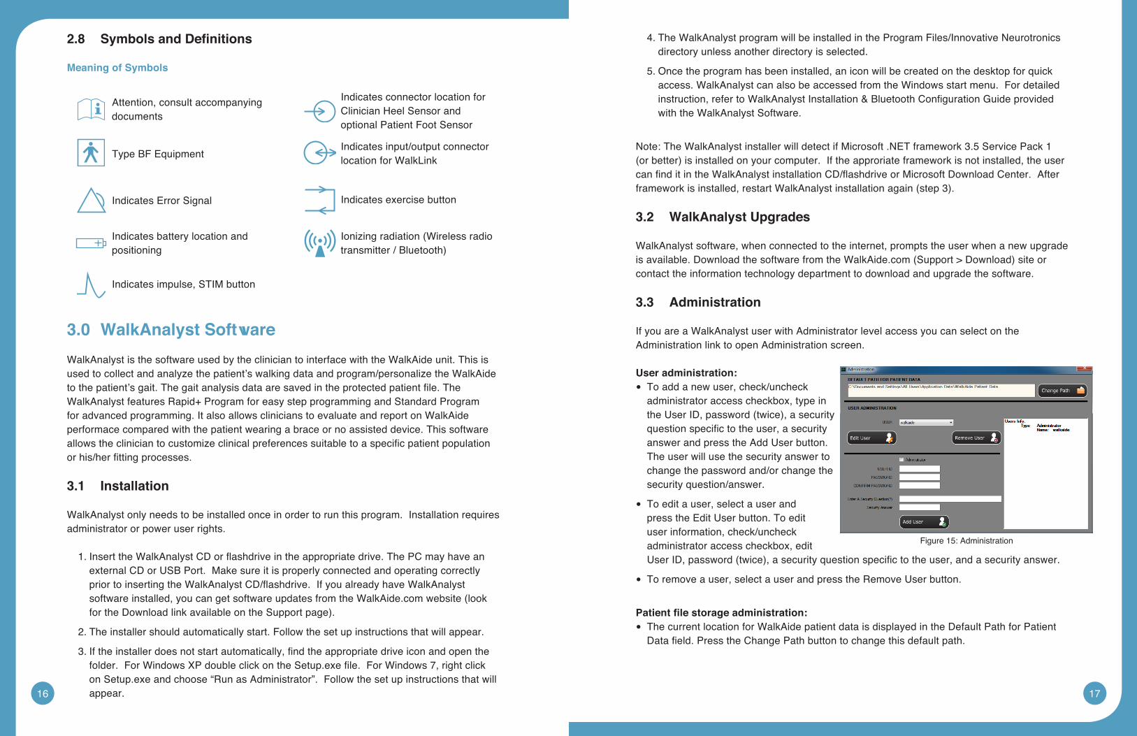
If you are a WalkAnalyst user with Administrator level access you can select on the Administration link to open Administration screen.
User administration: To add a new user, check/uncheck •administrator access checkbox, type in theUserID,password(twice),asecurityquestionspecifictotheuser,asecurityanswer and press the Add User button. The user will use the security answer to change the password and/or change the security question/answer.
To edit a user, select a user and •press the Edit User button. To edit user information, check/uncheck administrator access checkbox, edit UserID,password(twice),asecurityquestionspecifictotheuser,andasecurityanswer.
To remove a user, select a user and press the Remove User button. •
Patientfilestorageadministration:The current location for WalkAide patient data is displayed in the Default Path for Patient •Datafield.PresstheChangePathbuttontochangethisdefaultpath.
Figure 15: Administration
18 19
3.4 ChangingClinicalPreferences
WalkAnalyst software allows the clinician to modify default preferences.
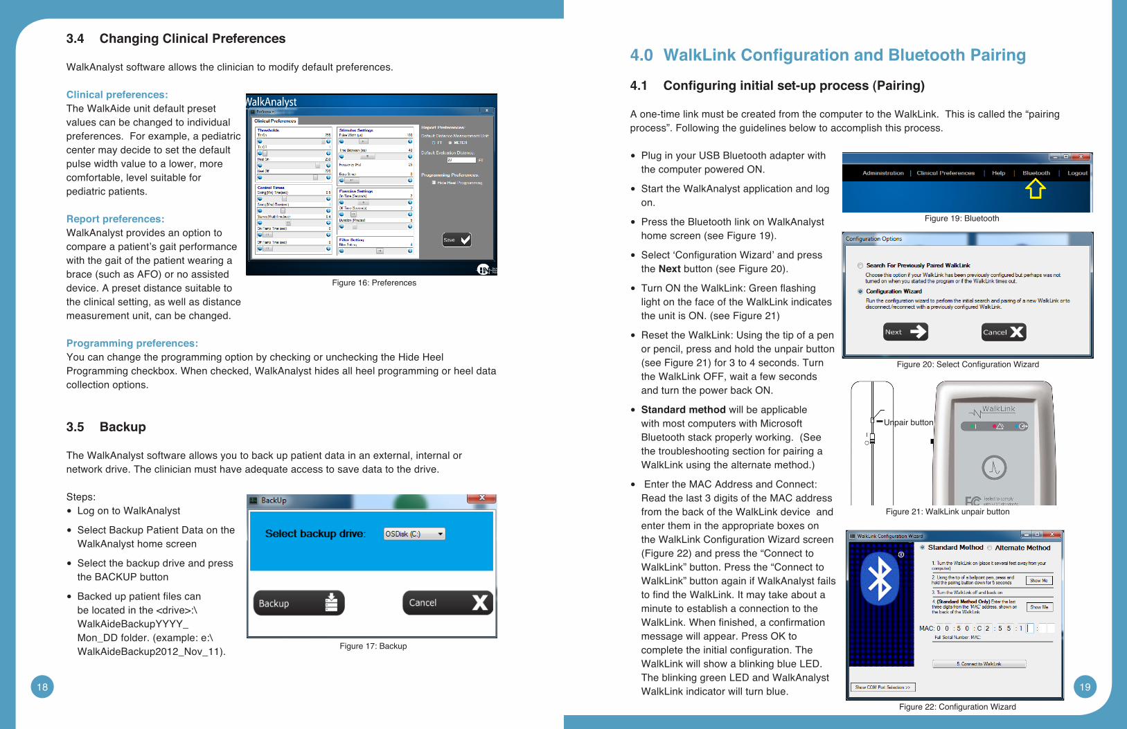
Clinical preferences:The WalkAide unit default preset values can be changed to individual preferences. For example, a pediatric center may decide to set the default pulse width value to a lower, more comfortable, level suitable for pediatric patients.
Report preferences:WalkAnalyst provides an option to compare a patient’s gait performance with the gait of the patient wearing a brace(suchasAFO)ornoassisteddevice. A preset distance suitable to the clinical setting, as well as distance measurement unit, can be changed.
Programmingpreferences:You can change the programming option by checking or unchecking the Hide Heel Programming checkbox. When checked, WalkAnalyst hides all heel programming or heel data collection options.
3.5 Backup
The WalkAnalyst software allows you to back up patient data in an external, internal or network drive. The clinician must have adequate access to save data to the drive.
Steps: Log on to WalkAnalyst •
Select Backup Patient Data on the •WalkAnalyst home screen
Select the backup drive and press •the BACKUP button
Backeduppatientfilescan •belocatedinthe<drive>:\WalkAideBackupYYYY_Mon_DDfolder.(example:e:\WalkAideBackup2012_Nov_11).
4.0 WalkLinkConfigurationandBluetoothPairing
4.1 Configuringinitialset-upprocess(Pairing)
A one-time link must be created from the computer to the WalkLink. This is called the “pairing process”. Following the guidelines below to accomplish this process.
Plug in your USB Bluetooth adapter with •the computer powered ON.
Start the WalkAnalyst application and log •on.
Press the Bluetooth link on WalkAnalyst •homescreen(seeFigure19).
Select‘ConfigurationWizard’andpress •the Nextbutton(seeFigure20).
TurnONtheWalkLink:Greenflashing •light on the face of the WalkLink indicates theunitisON.(seeFigure21)
Reset the WalkLink: Using the tip of a pen •or pencil, press and hold the unpair button (seeFigure21)for3to4seconds.Turnthe WalkLink OFF, wait a few seconds and turn the power back ON.
• Standardmethod will be applicable with most computers with Microsoft Bluetoothstackproperlyworking.(Seethe troubleshooting section for pairing a WalkLinkusingthealternatemethod.)
Enter the MAC Address and Connect: •Read the last 3 digits of the MAC address from the back of the WalkLink device and enter them in the appropriate boxes on theWalkLinkConfigurationWizardscreen(Figure22)andpressthe“ConnecttoWalkLink” button. Press the “Connect to WalkLink” button again if WalkAnalyst fails tofindtheWalkLink.Itmaytakeaboutaminute to establish a connection to the WalkLink.Whenfinished,aconfirmationmessage will appear. Press OK to completetheinitialconfiguration.TheWalkLink will show a blinking blue LED. The blinking green LED and WalkAnalyst WalkLink indicator will turn blue.
Figure 16: Preferences
Figure 17: Backup
Figure 19: Bluetooth
Figure20:SelectConfigurationWizard
Unpair button
Figure 21: WalkLink unpair button
Figure22:ConfigurationWizard
20 21
Note: IfthecomputerandtheWalkLinkwerepreviouslyconnected: Turn on the WalkLink and open the WalkAnalyst software program. The blue light on the front of the WalkLink should begin to blink. The WalkAide can be attached to the WalkLink at any time. The blue light in the upper left hand corner of the WalkAnalyst screen will indicate a solid connection to the WalkLink, and the green light will indicate a solid connection to the WalkAide.
5.0 FittingProcess
5.1 Pre-screeningwiththePeripheralNerveStimulator
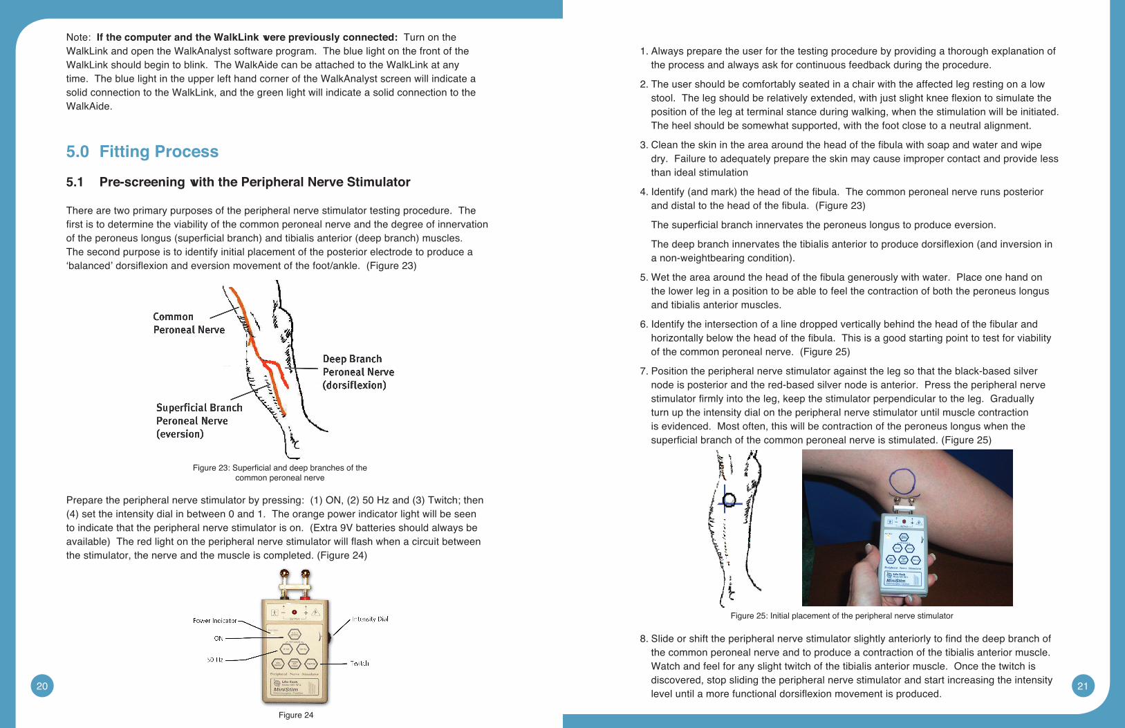
There are two primary purposes of the peripheral nerve stimulator testing procedure. The firstistodeterminetheviabilityofthecommonperonealnerveandthedegreeofinnervationoftheperoneuslongus(superficialbranch)andtibialisanterior(deepbranch)muscles.The second purpose is to identify initial placement of the posterior electrode to produce a ‘balanced’dorsiflexionandeversionmovementofthefoot/ankle.(Figure23)
Preparetheperipheralnervestimulatorbypressing:(1)ON,(2)50Hzand(3)Twitch;then(4)settheintensitydialinbetween0and1.Theorangepowerindicatorlightwillbeseentoindicatethattheperipheralnervestimulatorison.(Extra9Vbatteriesshouldalwaysbeavailable)Theredlightontheperipheralnervestimulatorwillflashwhenacircuitbetweenthestimulator,thenerveandthemuscleiscompleted.(Figure24)
1. Always prepare the user for the testing procedure by providing a thorough explanation of the process and always ask for continuous feedback during the procedure.
2. The user should be comfortably seated in a chair with the affected leg resting on a low stool.Thelegshouldberelativelyextended,withjustslightkneeflexiontosimulatetheposition of the leg at terminal stance during walking, when the stimulation will be initiated. The heel should be somewhat supported, with the foot close to a neutral alignment.
3.Cleantheskinintheareaaroundtheheadofthefibulawithsoapandwaterandwipedry. Failure to adequately prepare the skin may cause improper contact and provide less than ideal stimulation
4.Identify(andmark)theheadofthefibula.Thecommonperonealnerverunsposterioranddistaltotheheadofthefibula.(Figure23)
Thesuperficialbranchinnervatestheperoneuslongustoproduceeversion.
Thedeepbranchinnervatesthetibialisanteriortoproducedorsiflexion(andinversioninanon-weightbearingcondition).
5.Wettheareaaroundtheheadofthefibulagenerouslywithwater.Placeonehandonthe lower leg in a position to be able to feel the contraction of both the peroneus longus and tibialis anterior muscles.
6.Identifytheintersectionofalinedroppedverticallybehindtheheadofthefibularandhorizontallybelowtheheadofthefibula.Thisisagoodstartingpointtotestforviabilityofthecommonperonealnerve.(Figure25)
7. Position the peripheral nerve stimulator against the leg so that the black-based silver node is posterior and the red-based silver node is anterior. Press the peripheral nerve stimulatorfirmlyintotheleg,keepthestimulatorperpendiculartotheleg.Graduallyturn up the intensity dial on the peripheral nerve stimulator until muscle contraction is evidenced. Most often, this will be contraction of the peroneus longus when the superficialbranchofthecommonperonealnerveisstimulated.(Figure25)
8.Slideorshifttheperipheralnervestimulatorslightlyanteriorlytofindthedeepbranchofthe common peroneal nerve and to produce a contraction of the tibialis anterior muscle. Watch and feel for any slight twitch of the tibialis anterior muscle. Once the twitch is discovered, stop sliding the peripheral nerve stimulator and start increasing the intensity leveluntilamorefunctionaldorsiflexionmovementisproduced.
Figure23:Superficialanddeepbranchesofthecommon peroneal nerve
Figure 25: Initial placement of the peripheral nerve stimulator
Figure 24
22 23
9.Balancetheeversionanddorsiflexionmovementswithveryslightshiftingoftheperipheral nerve stimulator. After determining the most appropriate ‘balance’ point, mark the location of the posterior black-based node on the leg. This is the starting point for placement of the posterior electrode.
The location of the branching of the common peroneal nerve varies between individuals. Slow and methodical testing of the area will identify the most appropriate starting point for placement of the posterior black electrode.
5.2 ElectrodePlacementsandSystemPreparations
1. Turn the WalkAide OFF and attach the electrode lead cable to the back of the WalkAide. Directthecabletotherighttofitarightlegandtothelefttofitaleftleg.Thisallowsapproriate cable length to attach the electrodes and also prevents excessive bending or flexingoftheelectrodeleadcable.
2.AttachtheWalkAidetothecuffonthemedialflattenedarea.Positionthecuffaroundthemid-calf region and secure in place below the potential electrode sites. This places the WalkAide in a convenient location to hook up the electrodes.
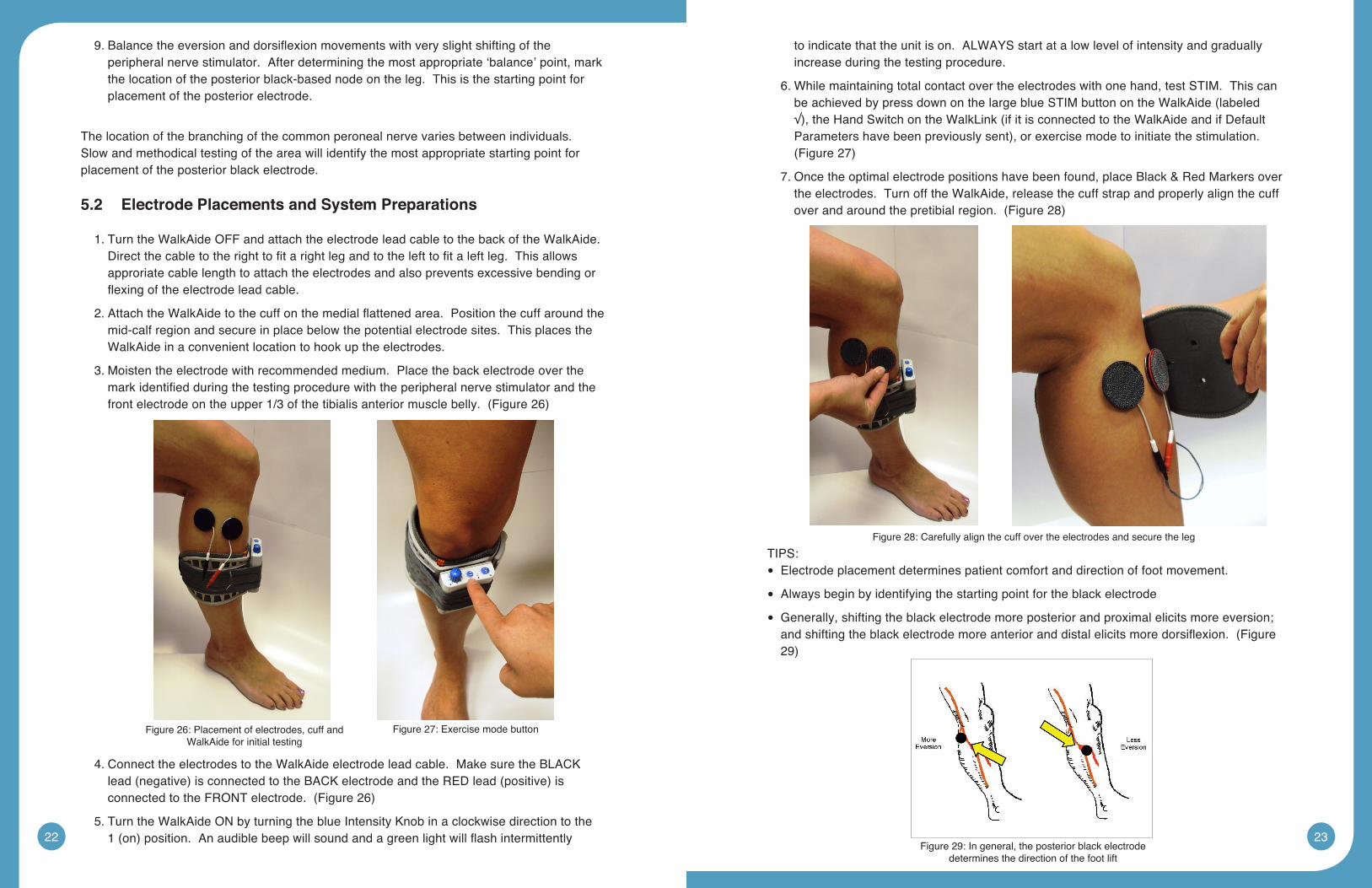
3. Moisten the electrode with recommended medium. Place the back electrode over the markidentifiedduringthetestingprocedurewiththeperipheralnervestimulatorandthefrontelectrodeontheupper1/3ofthetibialisanteriormusclebelly.(Figure26)
4. Connect the electrodes to the WalkAide electrode lead cable. Make sure the BLACK lead(negative)isconnectedtotheBACKelectrodeandtheREDlead(positive)isconnectedtotheFRONTelectrode.(Figure26)
5. Turn the WalkAide ON by turning the blue Intensity Knob in a clockwise direction to the 1(on)position.Anaudiblebeepwillsoundandagreenlightwillflashintermittently
to indicate that the unit is on. ALWAYS start at a low level of intensity and gradually increase during the testing procedure.
6. While maintaining total contact over the electrodes with one hand, test STIM. This can beachievedbypressdownonthelargeblueSTIMbuttonontheWalkAide(labeled√),theHandSwitchontheWalkLink(ifitisconnectedtotheWalkAideandifDefaultParametershavebeenpreviouslysent),orexercisemodetoinitiatethestimulation.(Figure27)
7. Once the optimal electrode positions have been found, place Black & Red Markers over the electrodes. Turn off the WalkAide, release the cuff strap and properly align the cuff overandaroundthepretibialregion.(Figure28)
TIPS: Electrode placement determines patient comfort and direction of foot movement. •
Always begin by identifying the starting point for the black electrode •
Generally, shifting the black electrode more posterior and proximal elicits more eversion; •andshiftingtheblackelectrodemoreanterioranddistalelicitsmoredorsiflexion.(Figure29)
Figure 26: Placement of electrodes, cuff and WalkAide for initial testing
Figure 27: Exercise mode button
Figure 28: Carefully align the cuff over the electrodes and secure the leg
Figure 29: In general, the posterior black electrode determines the direction of the foot lift
24 25
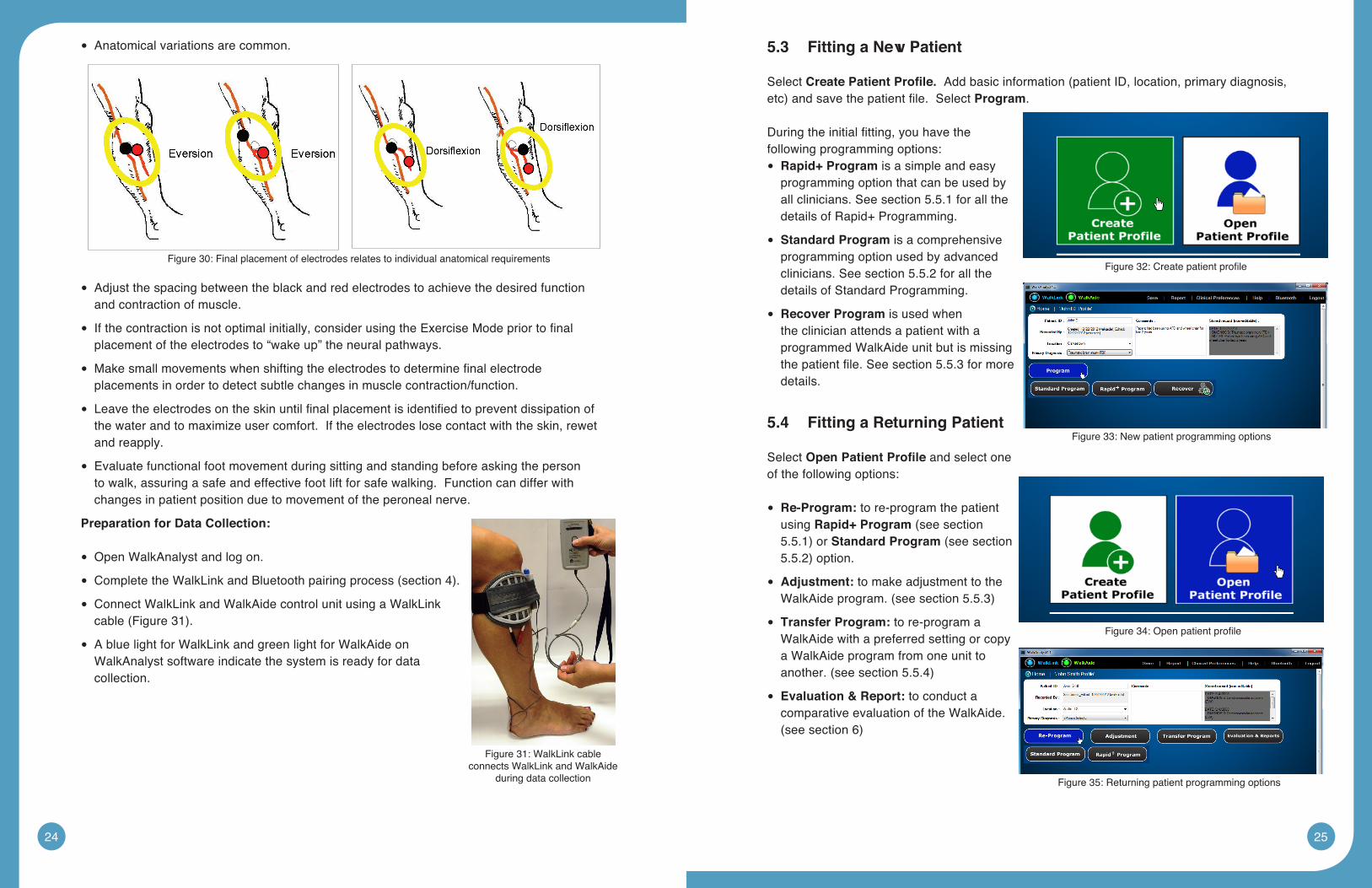
Anatomical variations are common. •
Adjust the spacing between the black and red electrodes to achieve the desired function •and contraction of muscle.
Ifthecontractionisnotoptimalinitially,considerusingtheExerciseModepriortofinal •placement of the electrodes to “wake up” the neural pathways.
Makesmallmovementswhenshiftingtheelectrodestodeterminefinalelectrode •placements in order to detect subtle changes in muscle contraction/function.
Leavetheelectrodesontheskinuntilfinalplacementisidentifiedtopreventdissipationof •the water and to maximize user comfort. If the electrodes lose contact with the skin, rewet and reapply.
Evaluate functional foot movement during sitting and standing before asking the person •to walk, assuring a safe and effective foot lift for safe walking. Function can differ with changes in patient position due to movement of the peroneal nerve.
PreparationforDataCollection:
Open WalkAnalyst and log on. •
CompletetheWalkLinkandBluetoothpairingprocess(section4). •
Connect WalkLink and WalkAide control unit using a WalkLink •cable(Figure31).
A blue light for WalkLink and green light for WalkAide on •WalkAnalyst software indicate the system is ready for data collection.
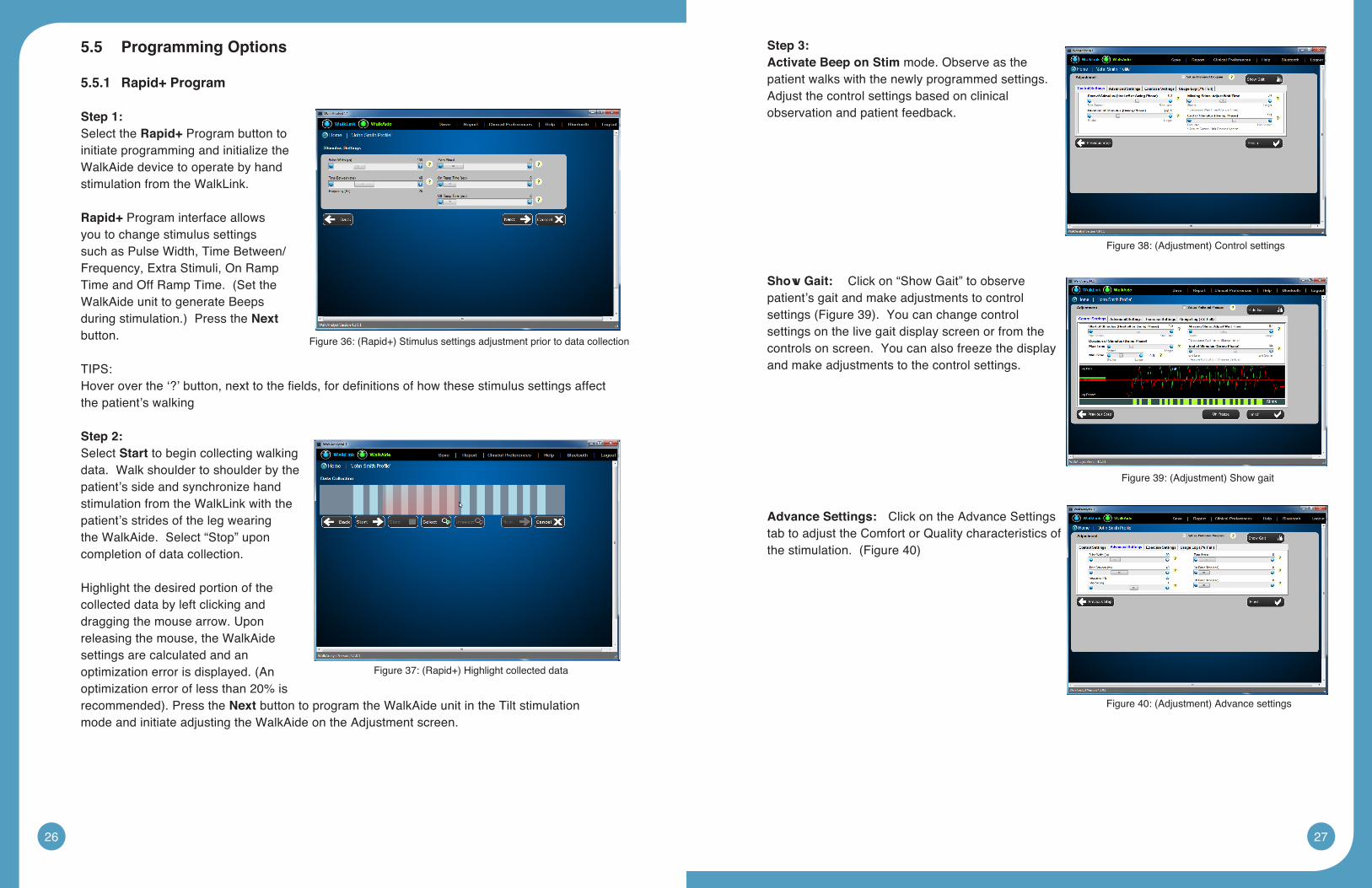
5.3 FittingaNewPatient
Select CreatePatientProfile.Addbasicinformation(patientID,location,primarydiagnosis,etc)andsavethepatientfile.SelectProgram.
Duringtheinitialfitting,youhavethefollowing programming options:Rapid+Program • is a simple and easy programming option that can be used by all clinicians. See section 5.5.1 for all the details of Rapid+ Programming.
• StandardProgram is a comprehensive programming option used by advanced clinicians. See section 5.5.2 for all the details of Standard Programming.
• RecoverProgram is used when the clinician attends a patient with a programmed WalkAide unit but is missing thepatientfile.Seesection5.5.3formoredetails.
5.4 FittingaReturningPatient
Select OpenPatientProfile and select one of the following options:
Re-Program: • to re-program the patient using Rapid+Program(seesection5.5.1)orStandardProgram(seesection5.5.2)option.
Adjustment: • to make adjustment to the WalkAideprogram.(seesection5.5.3)
• TransferProgram: to re-program a WalkAide with a preferred setting or copy a WalkAide program from one unit to another.(seesection5.5.4)
• Evaluation & Report: to conduct a comparative evaluation of the WalkAide. (seesection6)
Figure 30: Final placement of electrodes relates to individual anatomical requirements
Figure 31: WalkLink cable connects WalkLink and WalkAide
during data collection
Figure32:Createpatientprofile
Figure 33: New patient programming options
Figure34:Openpatientprofile
Figure 35: Returning patient programming options
26 27
5.5 ProgrammingOptions
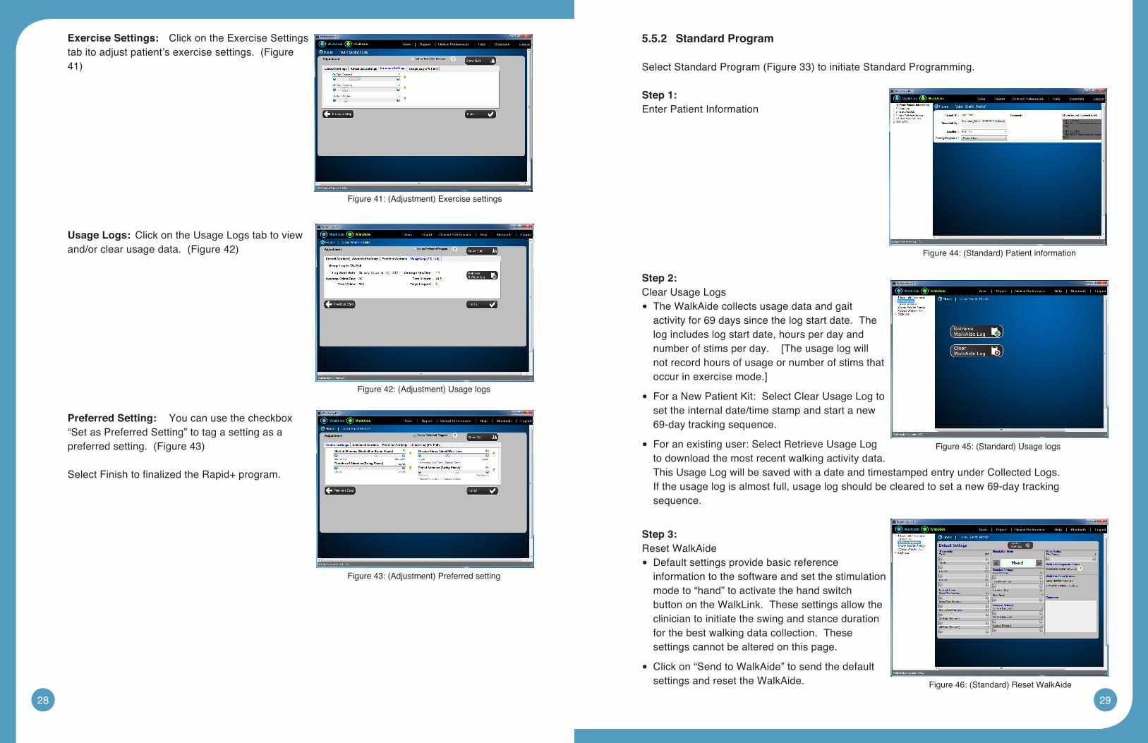
5.5.1 Rapid+Program
Step 1:Select the Rapid+ Program button to initiate programming and initialize the WalkAide device to operate by hand stimulation from the WalkLink.
Rapid+ Program interface allows you to change stimulus settings such as Pulse Width, Time Between/Frequency, Extra Stimuli, On Ramp TimeandOffRampTime.(SettheWalkAide unit to generate Beeps duringstimulation.)PresstheNext button.
TIPS:Hoveroverthe‘?’button,nexttothefields,fordefinitionsofhowthesestimulussettingsaffectthe patient’s walking
Step 2: Select Start to begin collecting walking data. Walk shoulder to shoulder by the patient’s side and synchronize hand stimulation from the WalkLink with the patient’s strides of the leg wearing the WalkAide. Select “Stop” upon completion of data collection.
Highlight the desired portion of the collected data by left clicking and dragging the mouse arrow. Upon releasing the mouse, the WalkAide settings are calculated and an optimizationerrorisdisplayed.(Anoptimization error of less than 20% is recommended).PresstheNext button to program the WalkAide unit in the Tilt stimulation mode and initiate adjusting the WalkAide on the Adjustment screen.
Step 3:ActivateBeeponStim mode. Observe as the patient walks with the newly programmed settings. Adjust the control settings based on clinical observation and patient feedback.
ShowGait: Click on “Show Gait” to observe patient’s gait and make adjustments to control settings(Figure39).Youcanchangecontrolsettings on the live gait display screen or from the controls on screen. You can also freeze the display and make adjustments to the control settings.
AdvanceSettings: Click on the Advance Settings tab to adjust the Comfort or Quality characteristics of thestimulation.(Figure40)
Figure36:(Rapid+)Stimulussettingsadjustmentpriortodatacollection
Figure37:(Rapid+)Highlightcollecteddata
Figure38:(Adjustment)Controlsettings
Figure39:(Adjustment)Showgait
Figure40:(Adjustment)Advancesettings
28 29
ExerciseSettings: Click on the Exercise Settings tabitoadjustpatient’sexercisesettings.(Figure41)
UsageLogs: Click on the Usage Logs tab to view and/orclearusagedata.(Figure42)
PreferredSetting: You can use the checkbox “Set as Preferred Setting” to tag a setting as a preferredsetting.(Figure43)
SelectFinishtofinalizedtheRapid+program.
5.5.2 StandardProgram
SelectStandardProgram(Figure33)toinitiateStandardProgramming.
Step 1:Enter Patient Information
Step 2:Clear Usage Logs
The WalkAide collects usage data and gait •activity for 69 days since the log start date. The log includes log start date, hours per day and number of stims per day. [The usage log will not record hours of usage or number of stims that occur in exercise mode.]
For a New Patient Kit: Select Clear Usage Log to •set the internal date/time stamp and start a new 69-day tracking sequence.
For an existing user: Select Retrieve Usage Log •to download the most recent walking activity data. This Usage Log will be saved with a date and timestamped entry under Collected Logs. If the usage log is almost full, usage log should be cleared to set a new 69-day tracking sequence.
Step 3:Reset WalkAide
Default settings provide basic reference •information to the software and set the stimulation mode to “hand” to activate the hand switch button on the WalkLink. These settings allow the clinician to initiate the swing and stance duration for the best walking data collection. These settings cannot be altered on this page.
Click on “Send to WalkAide” to send the default •settings and reset the WalkAide.
Figure41:(Adjustment)Exercisesettings
Figure42:(Adjustment)Usagelogs
Figure43:(Adjustment)Preferredsetting
Figure44:(Standard)Patientinformation
Figure45:(Standard)Usagelogs
Figure46:(Standard)ResetWalkAide
30 31
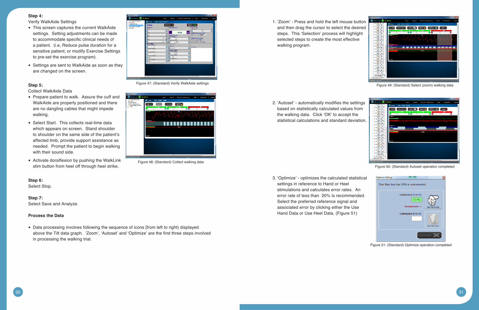
Step 4:VerifyWalkAideSettings
This screen captures the current WalkAide •settings. Setting adjustments can be made toaccommodatespecificclinicalneedsofapatient.(i.e,Reducepulsedurationforasensitive patient; or modify Exercise Settings topre-settheexerciseprogram).
Settings are sent to WalkAide as soon as they •are changed on the screen.
Step 5:Collect WalkAide Data
Prepare patient to walk. Assure the cuff and •WalkAide are properly positioned and there are no dangling cables that might impede walking.
Select Start. This collects real-time data •which appears on screen. Stand shoulder to shoulder on the same side of the patient’s affected limb, provide support assistance as needed. Prompt the patient to begin walking with their sound side.
ActivatedorsiflexionbypushingtheWalkLink •stim button from heel off through heel strike.
Step 6:Select Stop.
Step 7:Select Save and Analyze.
ProcesstheData
Dataprocessinginvolvesfollowingthesequenceoficons[fromlefttoright)displayed •abovetheTiltdatagraph.’Zoom’,‘Autoset’and‘Optimize’arethefirstthreestepsinvolvedin processing the walking trial.
1.‘Zoom’-Pressandholdtheleftmousebuttonand then drag the cursor to select the desired steps. This ‘Selection’ process will highlight selected steps to create the most effective walking program.
2.‘Autoset’-automaticallymodifiesthesettingsbased on statistically calculated values from the walking data. Click ‘OK’ to accept the statistical calculations and standard deviation.
3. ‘Optimize’ - optimizes the calculated statistical settings in reference to Hand or Heel stimulations and calculates error rates. An error rate of less than 20% is recommended. Select the preferred reference signal and associated error by clicking either the Use HandDataorUseHeelData.(Figure51)
Figure47:(Standard)VerifyWalkAidesettings
Figure48:(Standard)Collectwalkingdata
Figure49:(Standard)Select(zoom)walkingdata
Figure50:(Standard)Autosetoperationcompleted
Figure51:(Standard)Optimizeoperationcompleted
32 33
TIPS: If the error rates are greater than 20%: •
1. ResetZoomtoseeallDataandselectadifferentsequenceofstepsforOptimization, or
2. Collectanewwalkingtrialfordataprocessing.RepeattheZoom,AutosetandOptimize procedure.
The WalkAide unit is now programmed for the individual.
TIPS:CollectafinalwalkingtrialinTiltModetoverifyeffectiveandefficientprogrammingoftheWalkAide. Click CollectWalkingData and repeat the data collection procedure for a walking trialwiththeWalkAideinTiltMode(clickonCollectWalkingData,StopCollectingWalkingData,SaveandAnalyzethisWalkingData).
Thefinalwalkingtrialshouldrevealaneffectivepatternofstimulationandproduceasafeand symmetrical pattern of walking. Discuss the wearing schedule and care of the WalkAide unit. If any missing stimulations were noted, then make manual adjustments to the walking programasneeded.(referto8.2ManualAdjustmentoftheStimulationSettings.)
5.5.3 Adjustment
SettingadjustmentsaretransferredtotheWalkAideinstantaneouslyandareconfirmedbyaudible beeps. Activate WalkAide’s “Beep on Stim” mode. Select “Show Gait” button to display patient’s gait graphically.
ShowGait: Click on “Show Gait” to observe patient’s gait and make adjustments to control settings(Figure39).Youcanchangecontrolsettingsonthelivegaitdisplayscreenorfromthe controls on screen. You can also freeze the display and make adjustments to the control settings.
AdvanceSettings: Select the “Advance Settings” tab to adjust the comfort or quality characteristicsofthestimulation.(Figure40)
ExerciseSettings: Select “Exercise Settings” tab to adjust the patient’s exercise settings. (Figure41)
UsageLogs: Select“UsageLogs”tabtoviewand/orclearusagedata.(Figure42)
PreferredSetting: You can use the checkbox “Set as Preferred Setting” to tag a setting as preferredsetting.(Figure43)
Select FinishtofinalizetheAdjustment.
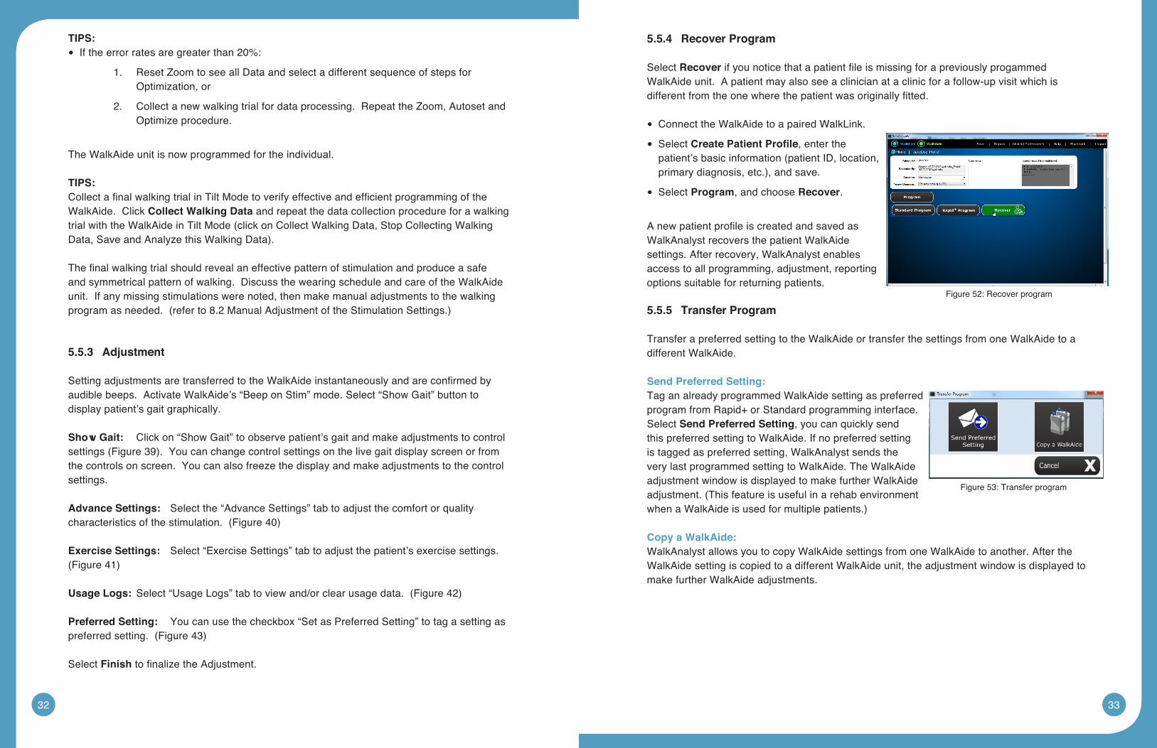
5.5.4 RecoverProgram
Select RecoverifyounoticethatapatientfileismissingforapreviouslyprogammedWalkAide unit. A patient may also see a clinician at a clinic for a follow-up visit which is differentfromtheonewherethepatientwasoriginallyfitted.
Connect the WalkAide to a paired WalkLink. •
Select • CreatePatientProfile, enter the patient’sbasicinformation(patientID,location,primarydiagnosis,etc.),andsave.
Select • Program, and choose Recover.
AnewpatientprofileiscreatedandsavedasWalkAnalyst recovers the patient WalkAide settings. After recovery, WalkAnalyst enables access to all programming, adjustment, reporting options suitable for returning patients.
5.5.5 TransferProgram
Transfer a preferred setting to the WalkAide or transfer the settings from one WalkAide to a different WalkAide.
SendPreferredSetting:Tag an already programmed WalkAide setting as preferred program from Rapid+ or Standard programming interface. Select SendPreferredSetting, you can quickly send this preferred setting to WalkAide. If no preferred setting is tagged as preferred setting, WalkAnalyst sends the very last programmed setting to WalkAide. The WalkAide adjustment window is displayed to make further WalkAide adjustment.(ThisfeatureisusefulinarehabenvironmentwhenaWalkAideisusedformultiplepatients.)
Copy a WalkAide:WalkAnalyst allows you to copy WalkAide settings from one WalkAide to another. After the WalkAide setting is copied to a different WalkAide unit, the adjustment window is displayed to make further WalkAide adjustments.
Figure 52: Recover program
Figure 53: Transfer program
34 35
5.6 ExerciseModeSettings
WalkAide can be used as a therapeutic modality, as an adjunct to therapy or as a way to condition the user’s nerve or muscle. It is intended to be used only while the user is seated. ChangetheExercisesettingsfromtheVerifyWalkAidesettingsscreenoftheStandardProgram(Figure47)orExerciseSettingstaboftheRapid+orAdjustmentscreen(Figure41).
The Exercise settings ranges are as follows: On Time: 1 - 5 seconds Off Time: 1 - 10 seconds Exercise Duration: 1 - 30 minutes
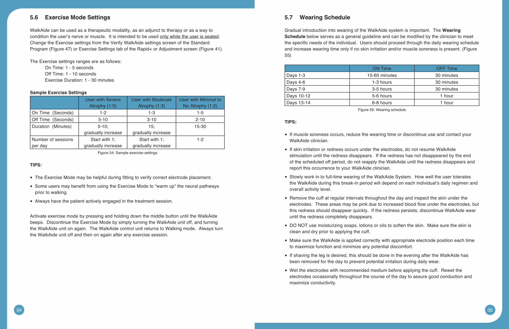
SampleExerciseSettings
User with Severe Atrophy(1:5)
User with Moderate Atrophy(1:3)
User with Minimal to NoAtrophy(1:2)
OnTime(Seconds) 1-2 1-3 1-5OffTime(Seconds) 5-10 3-10 2-10Duration(Minutes) 5-10;
gradually increase15;
gradually increase15-30
Number of sessions per day
Start with 1; gradually increase
Start with 1; gradually increase
1-2
Figure 54: Sample exercise settings
TIPS:
TheExerciseModemaybehelpfulduringfittingtoverifycorrectelectrodeplacement. •
SomeusersmaybenefitfromusingtheExerciseModeto“warmup”theneuralpathways •prior to walking.
Always have the patient actively engaged in the treatment session. •
Activate exercise mode by pressing and holding down the middle button until the WalkAide beeps. Discontinue the Exercise Mode by simply turning the WalkAide unit off, and turning the WalkAide unit on again. The WalkAide control unit returns to Walking mode. Always turn the WalkAide unit off and then on again after any exercise session.
5.7 WearingSchedule
Gradual introduction into wearing of the WalkAide system is important. The WearingSchedulebelowservesasageneralguidelineandcanbemodifiedbythecliniciantomeetthespecificneedsoftheindividual.Usersshouldproceedthroughthedailywearingscheduleandincreasewearingtimeonlyifnoskinirritationand/ormusclesorenessispresent.(Figure55)
ON Time OFF TimeDays 1-3 15-60 minutes 30 minutesDays 4-6 1-3 hours 30 minutesDays 7-9 3-5 hours 30 minutesDays 10-12 5-6 hours 1 hourDays 13-14 6-8 hours 1 hour
Figure 55: Wearing schedule
TIPS:
If muscle soreness occurs, reduce the wearing time or discontinue use and contact your •WalkAide clinician.
If skin irritation or redness occurs under the electrodes, do not resume WalkAide •stimulation until the redness disappears. If the redness has not disappeared by the end of the scheduled off period, do not reapply the WalkAide until the redness disappears and report this occurrence to your WalkAide clinician.
Slowly work in to full-time wearing of the WalkAide System. How well the user tolerates •the WalkAide during this break-in period will depend on each individual’s daily regimen and overall activity level.
Remove the cuff at regular intervals throughout the day and inspect the skin under the •electrodes.Theseareasmaybepinkduetoincreasedbloodflowundertheelectrodes,butthis redness should disappear quickly. If the redness persists, discontinue WalkAide wear until the redness completely disappears.
DO NOT use moisturizing soaps, lotions or oils to soften the skin. Make sure the skin is •clean and dry prior to applying the cuff.
Make sure the WalkAide is applied correctly with appropriate electrode position each time •to maximize function and minimize any potential discomfort.
If shaving the leg is desired, this should be done in the evening after the WalkAide has •been removed for the day to prevent potential irritation during daily wear.
Wet the electrodes with recommended medium before applying the cuff. Rewet the •electrodes occasionally throughout the course of the day to assure good conduction and maximize conductivity.
36 37
Precautions for WalkAide wear:
Skin irritation under the electrodes can occur in a small percentage of FES users. Common •causes of irritation are use of lotions or perfumed soaps, recent shaving, non-compliance with break-in schedule, failure to properly wet electrodes, poor electrode placement that forces an excessively high intensity level, and failure to change the electrodes often enough. The best way to avoid skin irritation is to increase to all day wear slowly, maintain proper skin hygiene, practice proper electrode care and choose the placement that allows for the least amount of stimulus intensity. Once irritation has occurred, the WalkAide must be discontinued until the skin is 100% clear of irritation. Using the WalkAide over irritated skin will only exacerbate the condition.
5.8 UsageLog
RetrieveUsageLog–AccessibleinStandardProgram(Figure45)ortheUsageLogs •tabontheAdjustmentscreen(Figure42).UsagedataduringWalkAideExerciseModeoperation are not part of the usage logs.
Collected logs section of the Standard Program archives displays all captured usage logs •labeled with the capture date.
The WalkAide unit collects usage data for up to 69 days since the last usage data reset •date and for the current date. To reset the WalkAide unit Usage log, click on the Clear Usage Log button from the Standard Program interface and Retrieve and Clear Usage logs button on the Adjustment screen.
Graphicalview(Totalhours/day,#ofStims/day) •
Tabularview(Totalhours/day,#ofStims/day) •
Reports – Select ‘Print’ icon in the upper right corner of the screen. Select any of the •walking trials to print a report showing the data analysis screen and associated parameters.
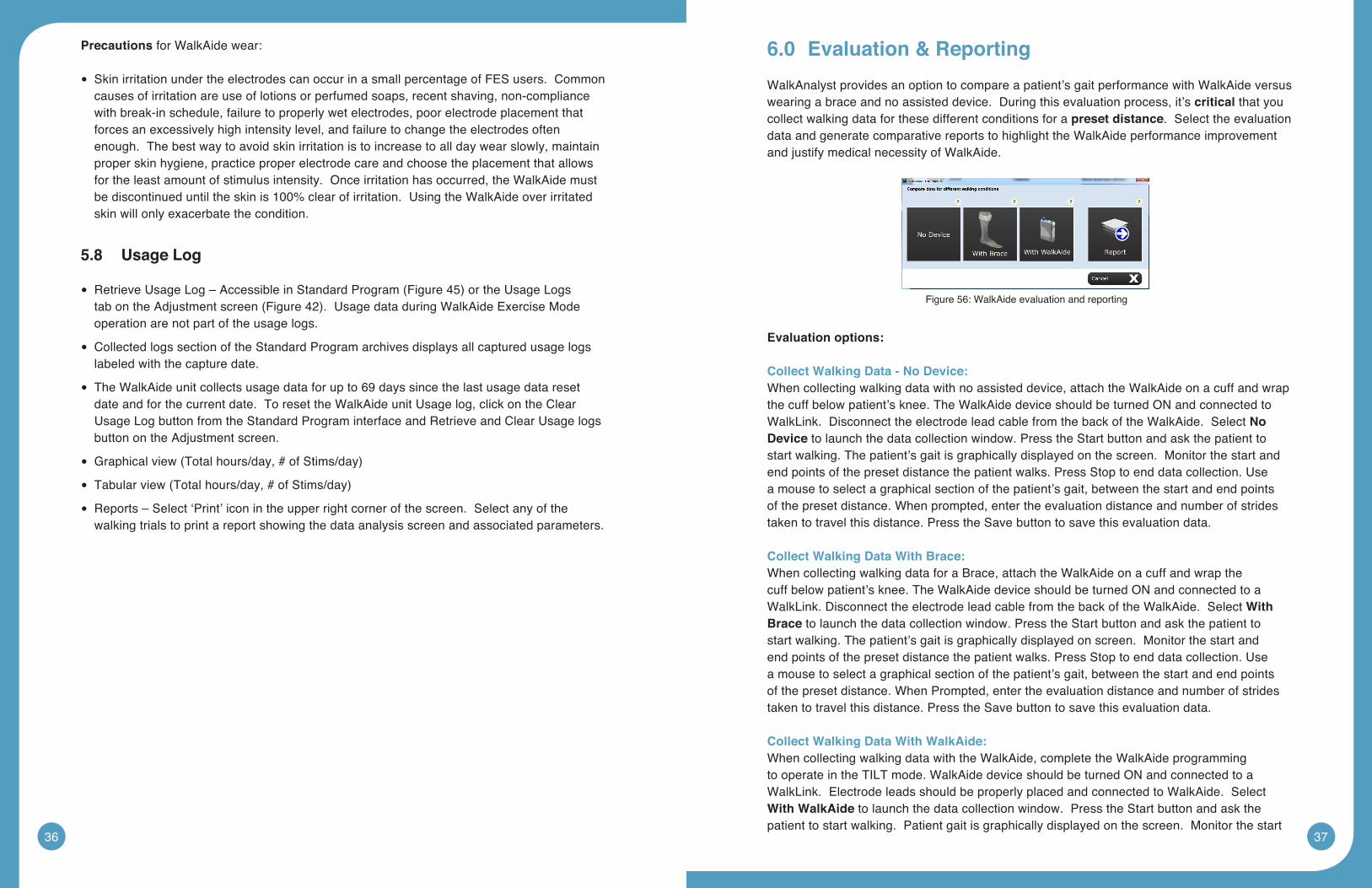
6.0 Evaluation&Reporting
WalkAnalyst provides an option to compare a patient’s gait performance with WalkAide versus wearing a brace and no assisted device. During this evaluation process, it’s critical that you collect walking data for these different conditions for a preset distance. Select the evaluation data and generate comparative reports to highlight the WalkAide performance improvement and justify medical necessity of WalkAide.
Evaluation options:
CollectWalkingData-NoDevice:When collecting walking data with no assisted device, attach the WalkAide on a cuff and wrap the cuff below patient’s knee. The WalkAide device should be turned ON and connected to WalkLink. Disconnect the electrode lead cable from the back of the WalkAide. Select No Device to launch the data collection window. Press the Start button and ask the patient to start walking. The patient’s gait is graphically displayed on the screen. Monitor the start and end points of the preset distance the patient walks. Press Stop to end data collection. Use a mouse to select a graphical section of the patient’s gait, between the start and end points of the preset distance. When prompted, enter the evaluation distance and number of strides taken to travel this distance. Press the Save button to save this evaluation data.
CollectWalkingDataWithBrace:When collecting walking data for a Brace, attach the WalkAide on a cuff and wrap the cuff below patient’s knee. The WalkAide device should be turned ON and connected to a WalkLink. Disconnect the electrode lead cable from the back of the WalkAide. Select WithBrace to launch the data collection window. Press the Start button and ask the patient to start walking. The patient’s gait is graphically displayed on screen. Monitor the start and end points of the preset distance the patient walks. Press Stop to end data collection. Use a mouse to select a graphical section of the patient’s gait, between the start and end points of the preset distance. When Prompted, enter the evaluation distance and number of strides taken to travel this distance. Press the Save button to save this evaluation data.
CollectWalkingDataWithWalkAide:When collecting walking data with the WalkAide, complete the WalkAide programming to operate in the TILT mode. WalkAide device should be turned ON and connected to a WalkLink. Electrode leads should be properly placed and connected to WalkAide. Select WithWalkAide to launch the data collection window. Press the Start button and ask the patient to start walking. Patient gait is graphically displayed on the screen. Monitor the start
Figure 56: WalkAide evaluation and reporting
38 39
and end points of the preset distance the patient walks. Press Stop to end data collection. Use a mouse to select a graphical section of the patient’s gait, between the start and end points of the preset distance. When Prompted, enter the evaluation distance. Press the Save button to save this evaluation data.
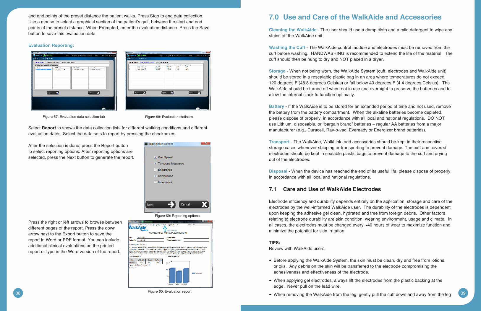
EvaluationReporting:
Select Report to shows the data collection lists for different walking conditions and different evaluation dates. Select the data sets to report by pressing the checkboxes.
After the selection is done, press the Report button to select reporting options. After reporting options are selected, press the Next button to generate the report.
Press the right or left arrows to browse between different pages of the report. Press the down arrow next to the Export button to save the report in Word or PDF format. You can include additional clinical evaluations on the printed report or type in the Word version of the report.
7.0 UseandCareoftheWalkAideandAccessories
CleaningtheWalkAide - The user should use a damp cloth and a mild detergent to wipe any stains off the WalkAide unit.
WashingtheCuff - The WalkAide control module and electrodes must be removed from the cuff before washing. HANDWASHING is recommended to extend the life of the material. The cuff should then be hung to dry and NOT placed in a dryer.
Storage-Whennotbeingworn,theWalkAideSystem(cuff,electrodesandWalkAideunit)should be stored in a resealable plastic bag in an area where temperatures do not exceed 120degreesF(48.8degreesCelsius)orfallbelow40degreesF(4.4degreesCelsius).TheWalkAide should be turned off when not in use and overnight to preserve the batteries and to allow the internal clock to function optimally.
Battery - If the WalkAide is to be stored for an extended period of time and not used, remove the battery from the battery compartment. When the alkaline batteries become depleted, please dispose of properly, in accordance with all local and national regulations. DO NOT use Lithium, disposable, or “bargain brand” batteries – regular AA batteries from a major manufacturer(e.g.,Duracell,Ray-o-vac,EvereadyorEnergizerbrandbatteries).
Transport - The WalkAide, WalkLink, and accessories should be kept in their respective storage cases whenever shipping or transporting to prevent damage. The cuff and covered electrodes should be kept in sealable plastic bags to prevent damage to the cuff and drying out of the electrodes.
Disposal - When the device has reached the end of its useful life, please dispose of properly, in accordance with all local and national regulations.
7.1 Care and Use of WalkAide Electrodes
Electrodeefficiencyanddurabilitydependsentirelyontheapplication,storageandcareoftheelectrodes by the well-informed WalkAide user. The durability of the electrodes is dependent upon keeping the adhesive gel clean, hydrated and free from foreign debris. Other factors relating to electrode durability are skin condition, wearing environment, usage and climate. In all cases, the electrodes must be changed every ~40 hours of wear to maximize function and minimize the potential for skin irritation.
TIPS:Review with WalkAide users,
Before applying the WalkAide System, the skin must be clean, dry and free from lotions •or oils. Any debris on the skin will be transferred to the electrode compromising the adhesiveness and effectiveness of the electrode.
When applying gel electrodes, always lift the electrodes from the plastic backing at the •edge. Never pull on the lead wire.
When removing the WalkAide from the leg, gently pull the cuff down and away from the leg •
Figure 57: Evaluation data selection tab Figure 58: Evaluation statistics
Figure 59: Reporting options
Figure 60: Evaluation report
40 41
in the same direction the hair lies. Never grasp the cuff and roughly pull away from the leg. Using a dab of water to separate the electrode from the skin can prolong electrode wear.
Always cover the gel electrodes with the plastic backing when not in use. Be sure the ‘on’ •side of the plastic piece is covering the gel.
Always store and seal the unit in the provided storage bag and keep in a cool dry place •whennotinuse.(Electrodesshouldbestoredattemperaturesof41˚to80˚F.Donotstoreinthefreezer/refrigerator,orleaveinextremeheat.)
Never submerge the electrodes in water. •
Re-hydrate the gel electrodes with a drop of water several times during daily wear. •
Electrodes are to be used for a single user. Never share electrodes or re-use on a second •person.
Never apply the electrodes to broken, blistered or irritated skin. •
If a rash or skin irritation occurs, discontinue use and contact the WalkAide clinician. It is •not appropriate to restart WalkAide wear until the skin is 100% clear of irritation or redness.
The electrodes must be replaced at least every 1 – 2 weeks, or sooner if the gel surface is •disrupted, appears to be dirty or if the quality or strength of the stimulation changes during use.
8.0 ClinicalTroubleshooting
8.1 ElectrodePlacementBestPractice
Accuracyofelectrodeplacementisthekeytotheefficient,comfortandfunctionalcontrolof foot lift. ‘Balanced’ placement of the electrodes promotes a safe and symmetrical gait whilepreservingmuscleendurance.Theclosertheblack(posterior)electrodeistoapositiondirectly over the motor nerve, the more comfortable the stimulation is for the user as precise positioning of the electrodes lessens the sensory response to the stimulation. The more precise the electrode placement, the stronger the muscle contraction at lower levels of intensity. The goal of electrode placement is to produce the most functional movement at the lowest intensity level so that the risks of muscle fatigue or skin irritation are minimized.
Black to the back and red ahead is the key phrase to remember when connecting the electrodes. The black electrode is negative and sends the stimulation into the leg. The red electrode is positive and forms a complete circuit to pull the stimulation out of the leg. The stimulation is optimized if it enters at the motor nerve and exits after traveling in the direction of the muscle. Electrode position varies with each patient.
Conductivity is enhanced by a complete circuit. Assuring a uniform electrode-skin interface. Applywatertotheelectrodes(andtheskinifdesired);makesurethatthereisnowaterbetween the electrodes. Spacing of the electrodes will also affect conduction of the stimulus signal:
1.Theclosertheelectrodes,themoresuperficialthecurrent;=moreeversion
2.Thefartheraparttheelectrodes,thedeeperthecurrent;=moredorsiflexion
8.2 ManualAdjustmentoftheStimulationSettings
Manualadjustmentofthesettingcanalwaysbeperformedbyfine-tuningswingandstanceduration. This process relies on the clinical judgment or the clinician and adjustment activities accessed through the Adjustment screen with the Show Gait option or the Standard program data collection graph.
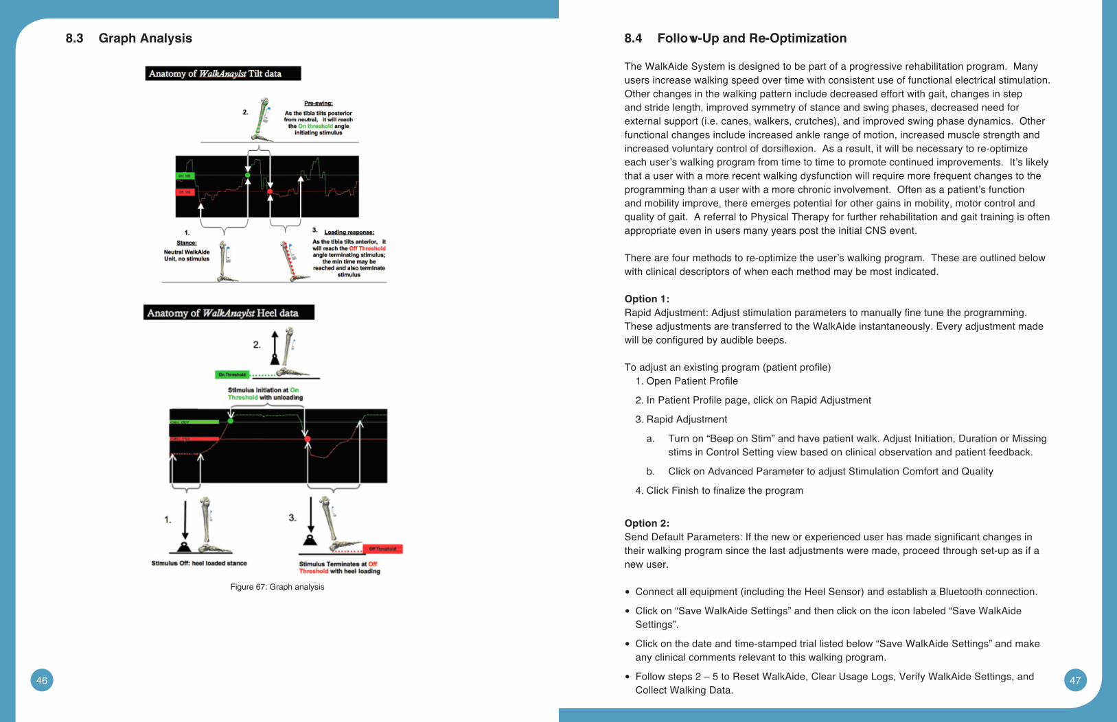
ON and OFF Thresholds: On and Off Thresholds trigger the timing of the initiation and terminationofthestimuliswingandstance(Figure67).
On Threshold - Stimulation initiates when the sensor value reaches the On threshold.
TheOnthreshold(horizontalsolidgreenline)maybetoohighandthesensorvaluenever •reaches it.
LoweringtheONthresholdtriggersstimtocomeonsooner(smallersteplength)RaisingtheONthresholddealystheONstimulus(longersteplength)
OFF Threshold - Stimulation terminates when the sensor value reaches the Off threshold.
TheOffthreshold(solidhorizontalorangeline)maybetoolow.Thevalueofthesensor •must go below this line after one stimulus is completed to allow another stimulus to be generated. To correct this, raise the Off threshold by clicking on the orange bar to the left of the graph screen area and dragging it higher.
The On and Off Thresholds may be adjusted over time as changes occur in walking speed, steplength,symmetry,easeofswing,amountofhipandkneeflexion,degreeofhypertonicity,etc,ortoachievespecifictherapeuticmodacities.
The numerical values listed as the On and Off thresholds relate to the range of tilt from vertical position available for measurement within the WalkAide unit itself. The numerical valuesarenotareportofhip,kneeoranklealignmentangles.Theclinicalsignificanceofthenumerical values is that a change in the numerical value of the threshold by a value of three is approximately one degree of tilt.
42 43
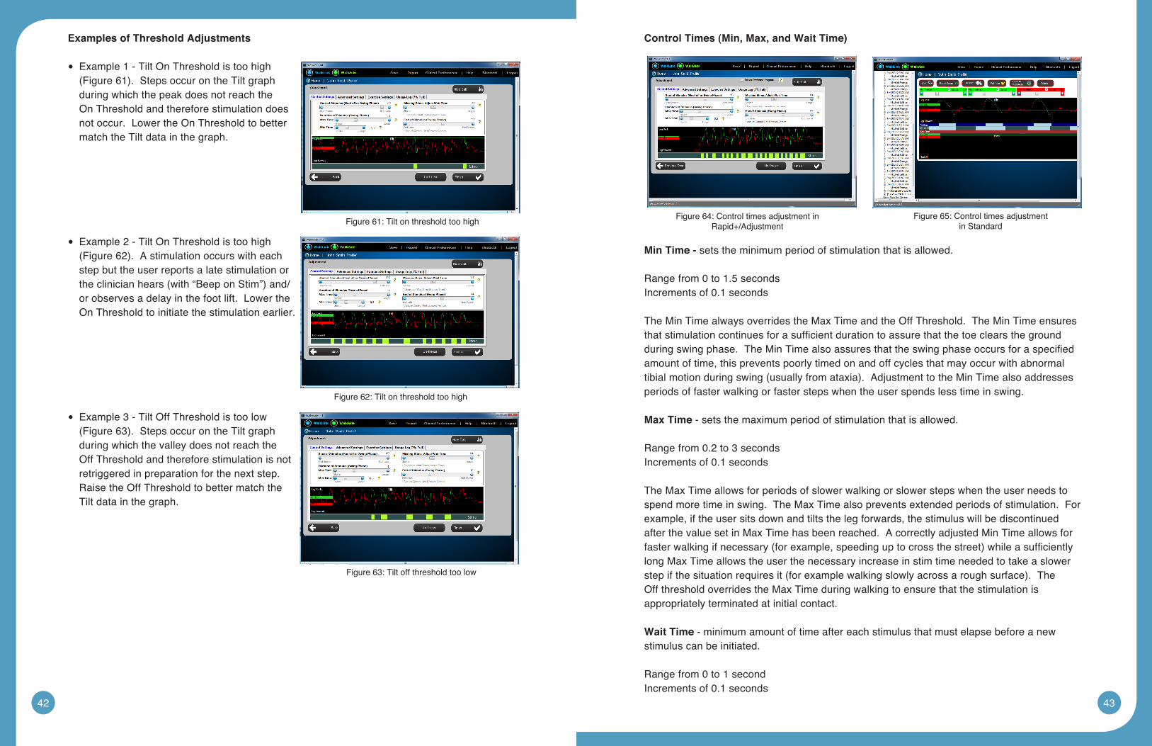
ExamplesofThresholdAdjustments
Example 1 - Tilt On Threshold is too high •(Figure61).StepsoccurontheTiltgraphduring which the peak does not reach the On Threshold and therefore stimulation does not occur. Lower the On Threshold to better match the Tilt data in the graph.
Example 2 - Tilt On Threshold is too high •(Figure62).Astimulationoccurswitheachstep but the user reports a late stimulation or theclinicianhears(with“BeeponStim”)and/or observes a delay in the foot lift. Lower the On Threshold to initiate the stimulation earlier.
Example 3 - Tilt Off Threshold is too low •(Figure63).StepsoccurontheTiltgraphduring which the valley does not reach the Off Threshold and therefore stimulation is not retriggered in preparation for the next step. Raise the Off Threshold to better match the Tilt data in the graph.
ControlTimes(Min,Max,andWaitTime)
Min Time - sets the minimum period of stimulation that is allowed. Range from 0 to 1.5 secondsIncrements of 0.1 seconds
The Min Time always overrides the Max Time and the Off Threshold. The Min Time ensures thatstimulationcontinuesforasufficientdurationtoassurethatthetoeclearsthegroundduringswingphase.TheMinTimealsoassuresthattheswingphaseoccursforaspecifiedamount of time, this prevents poorly timed on and off cycles that may occur with abnormal tibialmotionduringswing(usuallyfromataxia).AdjustmenttotheMinTimealsoaddressesperiods of faster walking or faster steps when the user spends less time in swing.
MaxTime - sets the maximum period of stimulation that is allowed.
Range from 0.2 to 3 secondsIncrements of 0.1 seconds
The Max Time allows for periods of slower walking or slower steps when the user needs to spend more time in swing. The Max Time also prevents extended periods of stimulation. For example, if the user sits down and tilts the leg forwards, the stimulus will be discontinued after the value set in Max Time has been reached. A correctly adjusted Min Time allows for fasterwalkingifnecessary(forexample,speedinguptocrossthestreet)whileasufficientlylong Max Time allows the user the necessary increase in stim time needed to take a slower stepifthesituationrequiresit(forexamplewalkingslowlyacrossaroughsurface).TheOff threshold overrides the Max Time during walking to ensure that the stimulation is appropriately terminated at initial contact.
Wait Time - minimum amount of time after each stimulus that must elapse before a new stimulus can be initiated.
Range from 0 to 1 secondIncrements of 0.1 seconds
Figure 61: Tilt on threshold too high
Figure 62: Tilt on threshold too high
Figure 63: Tilt off threshold too low
Figure 64: Control times adjustment in Rapid+/Adjustment
Figure 65: Control times adjustment in Standard
44 45
The Wait Time prevents the user from getting stimulated before stance phase can be completed(thismaybenecessaryiftheuserisataxicorflexesthestancekneeexcessivelyduringstance).TheWaitTimepreventsunwantedorinadvertentstimulationduringstancephase. As user’s increase their walking speed and spend less time in stance, a lower Wait Time will be necessary.
In general, the Min, Max and Wait Time values will be longer for slower walkers as they spend more time in swing and more time in stance. The Min, Max and Wait time values will be shorter for faster walkers as they spend less time in swing and less time in stance.
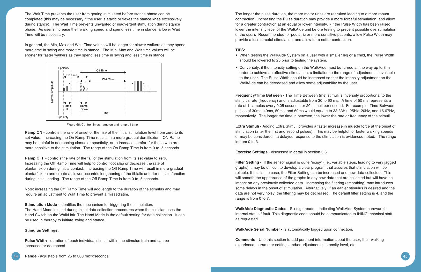
Ramp ON - controls the rate of onset or the rise of the initial stimulation level from zero to its setvalue.IncreasingtheOnRampTimeresultsinamoregradualdorsiflexion.ONRampmay be helpful in decreasing clonus or spasticity, or to increase comfort for those who are more sensitive to the stimulation. The range of the On Ramp Time is from 0 to .5 seconds.
Ramp OFF - controls the rate of the fall of the stimulation from its set value to zero. Increasing the Off Ramp Time will help to control foot slap or decrease the rate of plantarflexionduringinitialcontact.IncreasingtheOffRampTimewillresultinmoregradualplantarflexionandcreateaslowereccentriclengtheningofthetibialisanteriormusclefunctionduring initial loading. The range of the Off Ramp Time is from 0 to .5 seconds.
Note: increasing the Off Ramp Time will add length to the duration of the stimulus and may require an adjustment to Wait Time to prevent a missed stim.
Stimulation Mode-Identifiesthemechanismfortriggeringthestimulation.The Hand Mode is used during initial data collection procedures when the clinician uses the Hand Switch on the WalkLink. The Hand Mode is the default setting for data collection. It can be used in therapy to initiate swing and stance.
StimulusSettings:
PulseWidth - duration of each individual stimuli within the stimulus train and can be increased or decreased.
Range - adjustable from 25 to 300 microseconds.
The longer the pulse duration, the more motor units are recruited leading to a more robust contraction. Increasing the Pulse duration may provide a more forceful stimulation, and allow foragreatercontractionatanequalorlowerintensity.(IfthePulseWidthhasbeenraised,lower the intensity level of the WalkAide unit before testing to prevent possible overstimulation oftheuser).Recommendedforpediatricormoresensitivepatients,alowPulseWidthmayprovide a less forceful stimulation, and allow for a softer contraction.
TIPS:When testing the WalkAide System on a user with a smaller leg or a child, the Pulse Width •should be lowered to 25 prior to testing the system.
Conversely, if the intensity setting on the WalkAide must be turned all the way up to 8 in •order to achieve an effective stimulation, a limitation to the range of adjustment is available to the user. The Pulse Width should be increased so that the intensity adjustment on the WalkAide can be decreased and allow some adjustability by the user.
Frequency/TimeBetween-TheTimeBetween(ms)stimuliisinverselyproportionaltothestimulusrate(frequency)andisadjustablefrom30to60ms.Atimeof50msrepresentsarate of 1 stimulus every 0.05 seconds, or 20 stimuli per second. For example, Time Between pulses of 30ms, 40ms, 50ms, and 60ms would equate to 33.33Hz, 25Hz, 20Hz, and 16.67Hz, respectively. The longer the time in between, the lower the rate or frequency of the stimuli.
ExtraStimuli- Adding Extra Stimuli provides a faster increase in muscle force at the onset of stimulation(afterthefirstandsecondpulses).Thismaybehelpfulforfasterwalkingspeedsor may be considered if a delayed response to the stimulation is evidenced noted. The range is from 0 to 3.
ExerciseSettings - discussed in detail in section 5.6.
FilterSetting-Ifthesensorsignalisquite“noisy”(i.e.,variablesteps,leadingtoveryjaggedgraphs)itmaybedifficulttodevelopaclearprogramthatassuresthatstimulationwillbereliable. If this is the case, the Filter Setting can be increased and new data collected. This will smooth the appearance of the graphs in any new data that are collected but will have no impactonanypreviouslycollecteddata.Increasingthefiltering(smoothing)mayintroducessome delays in the onset of stimulation. Alternatively, if an earlier stimulus is desired and the dataarenotverynoisy,thefilteringmaybedecreased.Thedefaultfiltersettingis4,andtherange is from 0 to 7.
WalkAideDiagnosticCodes - Six digit readout indicating WalkAide System hardware’s internal status / fault. This diagnostic code should be communicated to ININC technical staff as requested.
WalkAide Serial Number - is automatically logged upon connection.
Comments - Use this section to add pertinent information about the user, their walking experience, parameter settings and/or adjustments, intensity level, etc.
Figure 66: Control times, ramp on and ramp off time
46 47
8.3 GraphAnalysis 8.4 Follow-Up and Re-Optimization
The WalkAide System is designed to be part of a progressive rehabilitation program. Many users increase walking speed over time with consistent use of functional electrical stimulation. Other changes in the walking pattern include decreased effort with gait, changes in step and stride length, improved symmetry of stance and swing phases, decreased need for externalsupport(i.e.canes,walkers,crutches),andimprovedswingphasedynamics.Otherfunctional changes include increased ankle range of motion, increased muscle strength and increasedvoluntarycontrolofdorsiflexion.Asaresult,itwillbenecessarytore-optimizeeach user’s walking program from time to time to promote continued improvements. It’s likely that a user with a more recent walking dysfunction will require more frequent changes to the programming than a user with a more chronic involvement. Often as a patient’s function and mobility improve, there emerges potential for other gains in mobility, motor control and quality of gait. A referral to Physical Therapy for further rehabilitation and gait training is often appropriate even in users many years post the initial CNS event.
There are four methods to re-optimize the user’s walking program. These are outlined below with clinical descriptors of when each method may be most indicated.
Option 1:RapidAdjustment:Adjuststimulationparameterstomanuallyfinetunetheprogramming.These adjustments are transferred to the WalkAide instantaneously. Every adjustment made willbeconfiguredbyaudiblebeeps.
Toadjustanexistingprogram(patientprofile)1.OpenPatientProfile
2.InPatientProfilepage,clickonRapidAdjustment
3. Rapid Adjustment
a. Turn on “Beep on Stim” and have patient walk. Adjust Initiation, Duration or Missing stims in Control Setting view based on clinical observation and patient feedback.
b. Click on Advanced Parameter to adjust Stimulation Comfort and Quality
4.ClickFinishtofinalizetheprogram
Option 2:SendDefaultParameters:Iftheneworexperienceduserhasmadesignificantchangesintheir walking program since the last adjustments were made, proceed through set-up as if a new user.
Connectallequipment(includingtheHeelSensor)andestablishaBluetoothconnection. •
Click on “Save WalkAide Settings” and then click on the icon labeled “Save WalkAide •Settings”.
Click on the date and time-stamped trial listed below “Save WalkAide Settings” and make •any clinical comments relevant to this walking program.
Followsteps2–5toResetWalkAide,ClearUsageLogs,VerifyWalkAideSettings,and •Collect Walking Data.
Figure 67: Graph analysis
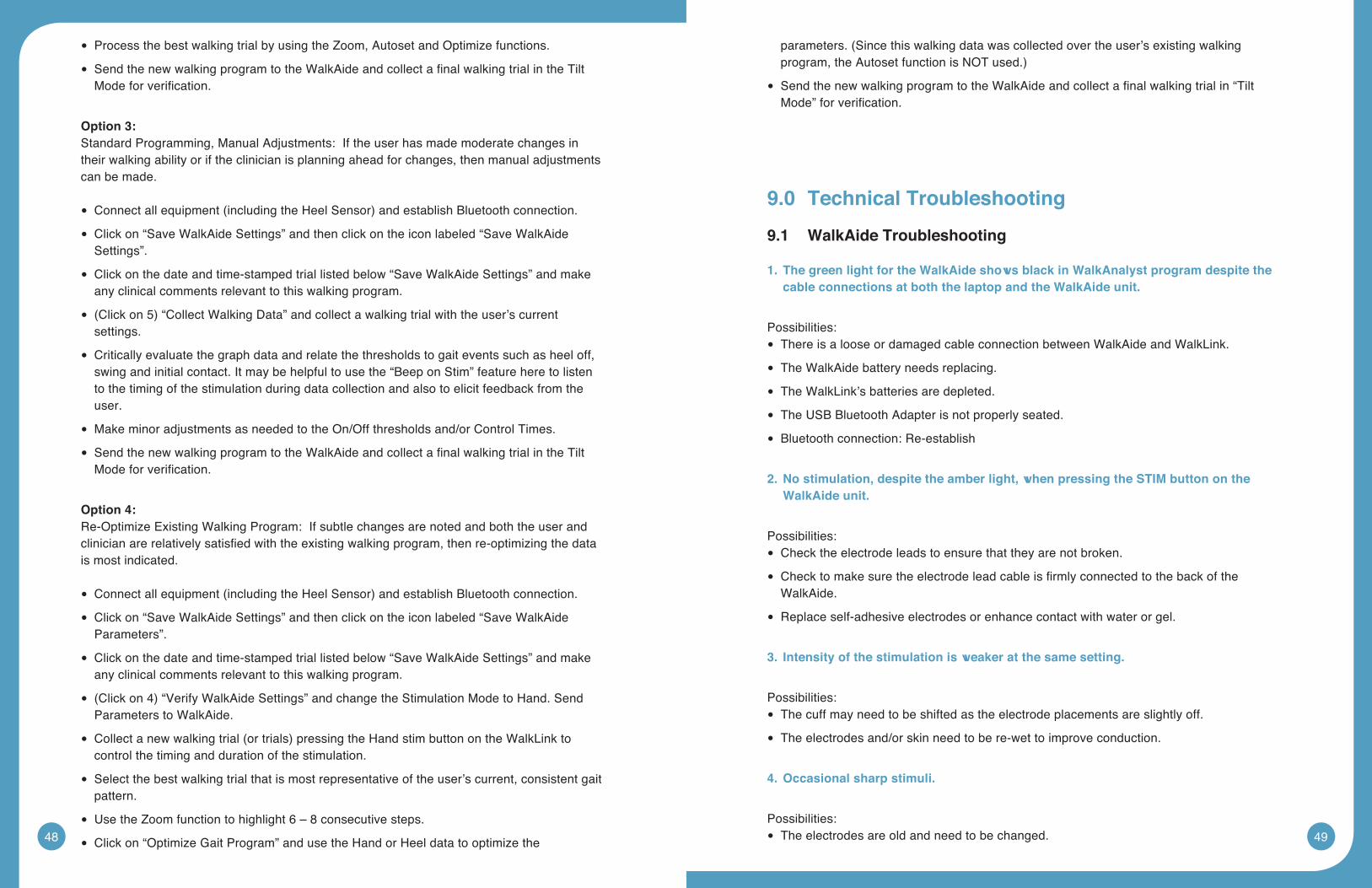
48 49
ProcessthebestwalkingtrialbyusingtheZoom,AutosetandOptimizefunctions. •
SendthenewwalkingprogramtotheWalkAideandcollectafinalwalkingtrialintheTilt •Modeforverification.
Option 3:Standard Programming, Manual Adjustments: If the user has made moderate changes in their walking ability or if the clinician is planning ahead for changes, then manual adjustments can be made.
Connectallequipment(includingtheHeelSensor)andestablishBluetoothconnection. •
Click on “Save WalkAide Settings” and then click on the icon labeled “Save WalkAide •Settings”.
Click on the date and time-stamped trial listed below “Save WalkAide Settings” and make •any clinical comments relevant to this walking program.
(Clickon5)“CollectWalkingData”andcollectawalkingtrialwiththeuser’scurrent •settings.
Critically evaluate the graph data and relate the thresholds to gait events such as heel off, •swing and initial contact. It may be helpful to use the “Beep on Stim” feature here to listen to the timing of the stimulation during data collection and also to elicit feedback from the user.
Make minor adjustments as needed to the On/Off thresholds and/or Control Times. •
SendthenewwalkingprogramtotheWalkAideandcollectafinalwalkingtrialintheTilt •Modeforverification.
Option 4:Re-Optimize Existing Walking Program: If subtle changes are noted and both the user and clinicianarerelativelysatisfiedwiththeexistingwalkingprogram,thenre-optimizingthedatais most indicated.
Connectallequipment(includingtheHeelSensor)andestablishBluetoothconnection. •
Click on “Save WalkAide Settings” and then click on the icon labeled “Save WalkAide •Parameters”.
Click on the date and time-stamped trial listed below “Save WalkAide Settings” and make •any clinical comments relevant to this walking program.
(Clickon4)“VerifyWalkAideSettings”andchangetheStimulationModetoHand.Send •Parameters to WalkAide.
Collectanewwalkingtrial(ortrials)pressingtheHandstimbuttonontheWalkLinkto •control the timing and duration of the stimulation.
Select the best walking trial that is most representative of the user’s current, consistent gait •pattern.
UsetheZoomfunctiontohighlight6–8consecutivesteps. •
Click on “Optimize Gait Program” and use the Hand or Heel data to optimize the •
parameters.(Sincethiswalkingdatawascollectedovertheuser’sexistingwalkingprogram,theAutosetfunctionisNOTused.)
SendthenewwalkingprogramtotheWalkAideandcollectafinalwalkingtrialin“Tilt •Mode”forverification.
9.0 TechnicalTroubleshooting
9.1 WalkAideTroubleshooting
1.ThegreenlightfortheWalkAideshowsblackinWalkAnalystprogramdespitethecableconnectionsatboththelaptopandtheWalkAideunit.
Possibilities:There is a loose or damaged cable connection between WalkAide and WalkLink. •
The WalkAide battery needs replacing. •
The WalkLink’s batteries are depleted. •
The USB Bluetooth Adapter is not properly seated. •
Bluetooth connection: Re-establish •
2.Nostimulation,despitetheamberlight,whenpressingtheSTIMbuttonontheWalkAide unit.
Possibilities:Check the electrode leads to ensure that they are not broken. •
Checktomakesuretheelectrodeleadcableisfirmlyconnectedtothebackofthe •WalkAide.
Replace self-adhesive electrodes or enhance contact with water or gel. •
3. Intensityofthestimulationisweakeratthesamesetting.
Possibilities: The cuff may need to be shifted as the electrode placements are slightly off. •
The electrodes and/or skin need to be re-wet to improve conduction. •
4.Occasionalsharpstimuli.
Possibilities:The electrodes are old and need to be changed. •
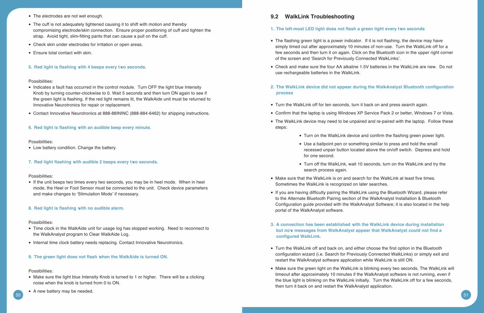
50 51
The electrodes are not wet enough. •
The cuff is not adequately tightened causing it to shift with motion and thereby •compromising electrode/skin connection. Ensure proper positioning of cuff and tighten the strap.Avoidtight,slim-fittingpantsthatcancauseapullonthecuff.
Check skin under electrodes for irritation or open areas. •
Ensure total contact with skin. •
5.Redlightisflashingwith4beepseverytwoseconds.
Possibilities:
Indicates a fault has occurred in the control module. Turn OFF the light blue Intensity •Knob by turning counter-clockwise to 0. Wait 5 seconds and then turn ON again to see if thegreenlightisflashing.Iftheredlightremainslit,theWalkAideunitmustbereturnedtoInnovative Neurotronics for repair or replacement.
ContactInnovativeNeurotronicsat888-88ININC(888-884-6462)forshippinginstructions. •
6.Redlightisflashingwithanaudiblebeepeveryminute.
Possibilities:
Low battery condition. Change the battery. •
7.Redlightflashingwithaudible2beepseverytwoseconds.
Possibilities:
If the unit beeps two times every two seconds, you may be in heel mode. When in heel •mode, the Heel or Foot Sensor must be connected to the unit. Check device parameters and make changes to ‘Stimulation Mode’ if necessary.
8.Redlightisflashingwithnoaudiblealarm.
Possibilities:
Time clock in the WalkAide unit for usage log has stopped working. Need to reconnect to •the WalkAnalyst program to Clear WalkAide Log.
Internal time clock battery needs replacing. Contact Innovative Neurotronics. •
9.ThegreenlightdoesnotflashwhentheWalkAideisturnedON.
Possibilities:
Make sure the light blue Intensity Knob is turned to 1 or higher. There will be a clicking •noise when the knob is turned from 0 to ON.
A new battery may be needed. •
9.2 WalkLinkTroubleshooting
1.Theleft-mostLEDlightdoesnotflashagreenlighteverytwoseconds
Theflashinggreenlightisapowerindicator.Ifitisnotflashing,thedevicemayhave •simply timed out after approximately 10 minutes of non-use. Turn the WalkLink off for a few seconds and then turn it on again. Click on the Bluetooth icon in the upper right corner of the screen and ‘Search for Previously Connected WalkLinks’.
CheckandmakesurethefourAAalkaline1.5VbatteriesintheWalkLinkarenew.Donot •use rechargeable batteries in the WalkLink.
2.TheWalkLinkdevicedidnotappearduringtheWalkAnalystBluetoothconfigurationprocess
Turn the WalkLink off for ten seconds, turn it back on and press search again. •
ConfirmthatthelaptopisusingWindowsXPServicePack2orbetter,Windows7orVista. •
The WalkLink device may need to be unpaired and re-paired with the laptop. Follow these •steps:
TurnontheWalkLinkdeviceandconfirmtheflashinggreenpowerlight. •
Use a ballpoint pen or something similar to press and hold the small •recessed unpair button located above the on/off switch. Depress and hold for one second.
Turn off the WalkLink, wait 10 seconds, turn on the WalkLink and try the •search process again.
MakesurethattheWalkLinkisonandsearchfortheWalkLinkatleastfivetimes. •Sometimes the WalkLink is recognized on later searches.
IfyouarehavingdifficultypairingtheWalkLinkusingtheBluetoothWizard,pleaserefer •to the Alternate Bluetooth Pairing section of the WalkAnalyst Installation & Bluetooth ConfigurationguideprovidedwiththeWalkAnalystSoftware;itisalsolocatedinthehelpportal of the WalkAnalyst software.
3.AconnectionhasbeenestablishedwiththeWalkLinkdeviceduringinstallationbutnowmessagesfromWalkAnalystappearthatWalkAnalystcouldnotfindaconfiguredWalkLink.
TurntheWalkLinkoffandbackon,andeitherchoosethefirstoptionintheBluetooth •configurationwizard(i.e.SearchforPreviouslyConnectedWalkLinks)orsimplyexitandrestart the WalkAnalyst software application while WalkLink is still ON.
Make sure the green light on the WalkLink is blinking every two seconds. The WalkLink will •timeout after approximately 10 minutes if the WalkAnalyst software is not running, even if the blue light is blinking on the WalkLink initially. Turn the WalkLink off for a few seconds, then turn it back on and restart the WalkAnalyst application.
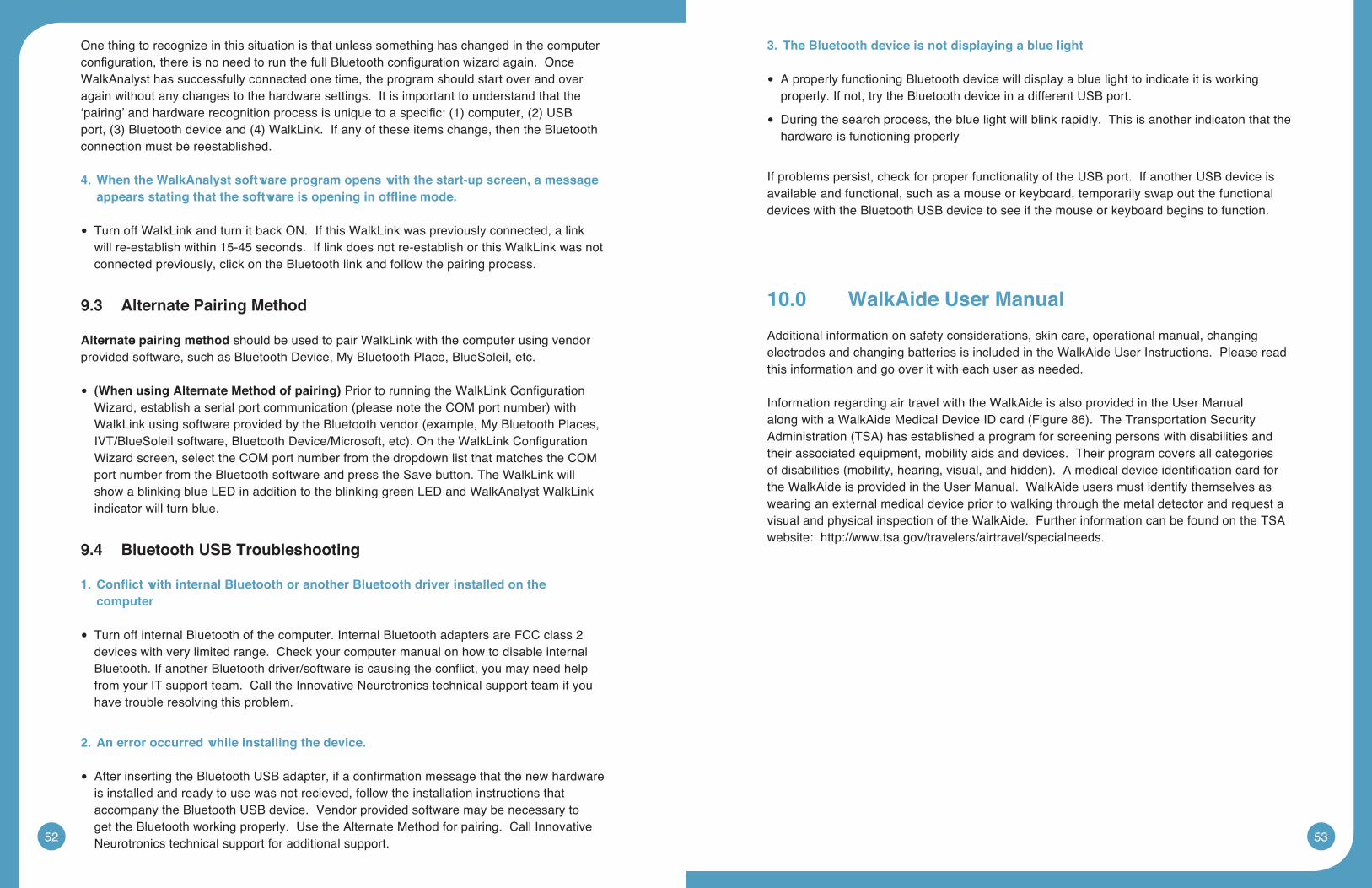
52 53
One thing to recognize in this situation is that unless something has changed in the computer configuration,thereisnoneedtorunthefullBluetoothconfigurationwizardagain.OnceWalkAnalyst has successfully connected one time, the program should start over and over again without any changes to the hardware settings. It is important to understand that the ‘pairing’andhardwarerecognitionprocessisuniquetoaspecific:(1)computer,(2)USBport,(3)Bluetoothdeviceand(4)WalkLink.Ifanyoftheseitemschange,thentheBluetoothconnection must be reestablished.
4.WhentheWalkAnalystsoftwareprogramopenswiththestart-upscreen,amessageappearsstatingthatthesoftwareisopeninginofflinemode.
Turn off WalkLink and turn it back ON. If this WalkLink was previously connected, a link •will re-establish within 15-45 seconds. If link does not re-establish or this WalkLink was not connected previously, click on the Bluetooth link and follow the pairing process.
9.3 AlternatePairingMethod
Alternatepairingmethodshould be used to pair WalkLink with the computer using vendor provided software, such as Bluetooth Device, My Bluetooth Place, BlueSoleil, etc.
(WhenusingAlternateMethodofpairing) • PriortorunningtheWalkLinkConfigurationWizard,establishaserialportcommunication(pleasenotetheCOMportnumber)withWalkLinkusingsoftwareprovidedbytheBluetoothvendor(example,MyBluetoothPlaces,IVT/BlueSoleilsoftware,BluetoothDevice/Microsoft,etc).OntheWalkLinkConfigurationWizard screen, select the COM port number from the dropdown list that matches the COM port number from the Bluetooth software and press the Save button. The WalkLink will show a blinking blue LED in addition to the blinking green LED and WalkAnalyst WalkLink indicator will turn blue.
9.4 BluetoothUSBTroubleshooting
1.ConflictwithinternalBluetoothoranotherBluetoothdriverinstalledonthecomputer
Turn off internal Bluetooth of the computer. Internal Bluetooth adapters are FCC class 2 •devices with very limited range. Check your computer manual on how to disable internal Bluetooth.IfanotherBluetoothdriver/softwareiscausingtheconflict,youmayneedhelpfrom your IT support team. Call the Innovative Neurotronics technical support team if you have trouble resolving this problem.
2.Anerroroccurredwhileinstallingthedevice.
AfterinsertingtheBluetoothUSBadapter,ifaconfirmationmessagethatthenewhardware •is installed and ready to use was not recieved, follow the installation instructions that accompanytheBluetoothUSBdevice.Vendorprovidedsoftwaremaybenecessarytoget the Bluetooth working properly. Use the Alternate Method for pairing. Call Innovative Neurotronics technical support for additional support.
3.TheBluetoothdeviceisnotdisplayingabluelight
A properly functioning Bluetooth device will display a blue light to indicate it is working •properly. If not, try the Bluetooth device in a different USB port.
During the search process, the blue light will blink rapidly. This is another indicaton that the •hardware is functioning properly
If problems persist, check for proper functionality of the USB port. If another USB device is available and functional, such as a mouse or keyboard, temporarily swap out the functional devices with the Bluetooth USB device to see if the mouse or keyboard begins to function.
10.0 WalkAide User Manual
Additional information on safety considerations, skin care, operational manual, changing electrodes and changing batteries is included in the WalkAide User Instructions. Please read this information and go over it with each user as needed.
Information regarding air travel with the WalkAide is also provided in the User Manual alongwithaWalkAideMedicalDeviceIDcard(Figure86).TheTransportationSecurityAdministration(TSA)hasestablishedaprogramforscreeningpersonswithdisabilitiesandtheir associated equipment, mobility aids and devices. Their program covers all categories ofdisabilities(mobility,hearing,visual,andhidden).Amedicaldeviceidentificationcardforthe WalkAide is provided in the User Manual. WalkAide users must identify themselves as wearing an external medical device prior to walking through the metal detector and request a visual and physical inspection of the WalkAide. Further information can be found on the TSA website: http://www.tsa.gov/travelers/airtravel/specialneeds.
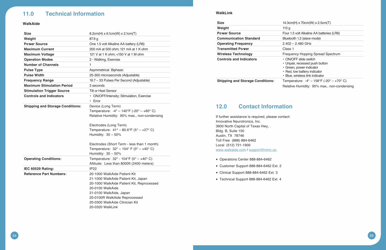
54 55
11.0 TechnicalInformation
WalkAide
Size 8.2cm(H)x6.1cm(W)x2.1cm(T)Weight 87.9 gPowerSource One1.5voltAlkalineAAbattery(LR6)MaximumCurrent 200 mA at 500 ohm; 121 mA at 1 K ohmMaximumVoltage 121Vat1Kohm;<150Vat1MohmOperation Modes 2 - Walking, ExerciseNumberofChannels 1PulseType Asymmetrical BiphasicPulseWidth 25-300microseconds(Adjustable)FrequencyRange 16.7–33PulsesPerSecond(Adjustable)MaximumStimulationPeriod 3 secondsStimulationTriggerSource Tilt or Heel SensorControls and Indicators •ON/OFF/Intensity;Stimulation,Exercise
•ErrorShippingandStorageConditions: Device(LongTerm)
Temperature:-4°–140°F(-20°–+60°C) Relative Humidity: 95% max., non-condensing
Electrodes(LongTerm)Temperature:41°–80.6°F(5°–+27°C)Humidity: 35 – 50%
Electrodes(ShortTerm-lessthan1month)Temperature:32°–104°F(0°–+40°C)Humidity: 35 – 50%
OperatingConditions: Temperature:32°-104°F(0°–+40°C)Altitude:Lessthan8000ft(2400meters)
IEC60529Rating: IP22ReferencePartNumbers: 20-1000 WalkAide Patient Kit
21-1000 WalkAide Patient Kit, Japan20-1000 WalkAide Patient Kit, Reprocessed20-0100 WalkAide21-0100 WalkAide, Japan20-0100R WalkAide Reprocessed20-0300 WalkAide Clinician Kit20-0320 WalkLink
WalkLink
Size 14.3cm(H)x70cm(W)x2.5cm(T)Weight 113 gPowerSource Four1.5voltAlkalineAAbatteries(LR6)Communication Standard Bluetooth1.2(slavemode)OperatingFrequency 2.402 – 2.480 GHzTransmittedPower Class 1WirelessTechnology Frequency Hopping Spread SpectrumControls and Indicators •ON/OFFslideswitch
•Unpair,recessedpushbutton•Green,powerindicator•Red,lowbatteryindicator•Blue,wirelesslinkindicator
ShippingandStorageConditions: Temperature:-4°–158°F(-20°–+70°C)
Relative Humidity: 95% max., non-condensing
12.0 Contact Information
If further assistance is required, please contact:Innovative Neurotronics, Inc.3600 North Capital of Texas Hwy, .Bldg. B, Suite 150Austin,TX78746TollFree(888)884-6462Local(512)721-1900www.walkaide.com / [email protected]
Operations Center 888-884-6462 •
Customer Support 888-884-6462 Ext. 2 •
Clinical Support 888-884-6462 Ext. 3 •
Technical Support 888-884-6462 Ext. 4 •