Embed Size (px)
Citation preview
Wakes and Shocksin Plasmas
Chan JoshiUCLA
Supported by DOE and NSFMIPSE Colloquium U. Michigan

Leonardo deVinci: Study of Wakes-1509
What is a Wake?
Structure of the displaced fluid behind an object causing disturbance
Neptune Laboratory
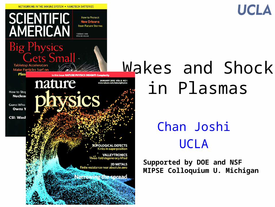
What is a Shock?
Subsonic Sonic Supersonic
A disturbance that travels at supersonic speeds through a medium
• At supersonic speeds, pressure will build at the front of a disturbance forming a shock
• Characterized by a rapid change in pressure (density and/or temperature) of the medium
In a plasma, a shock wave is characterized by a propagating electric field at speeds useful for ion acceleration (Vsh > 0.01c)
Object
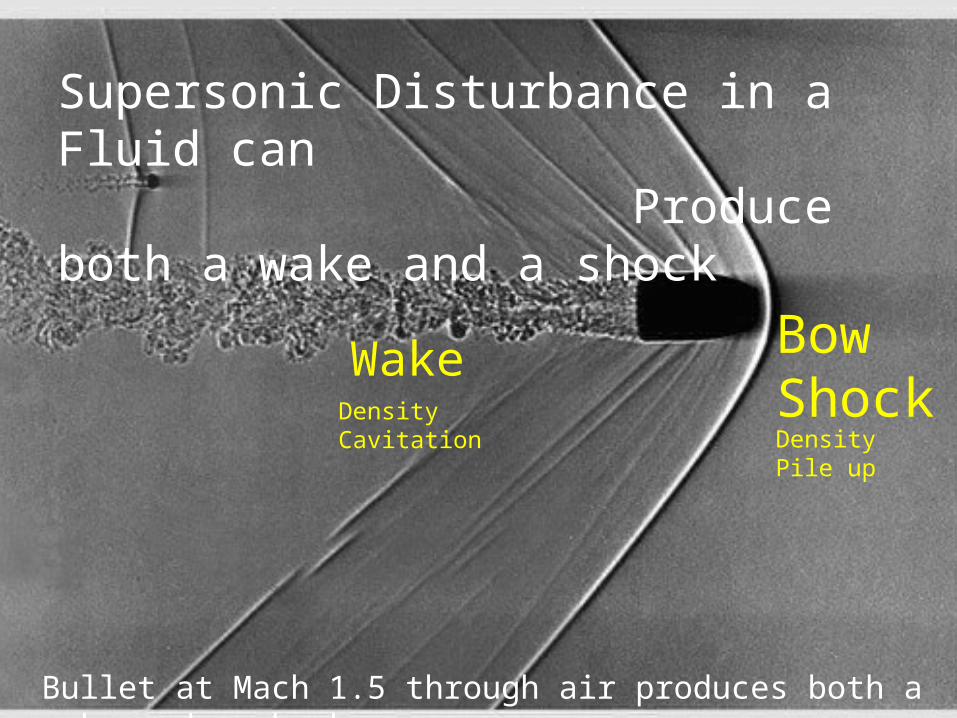
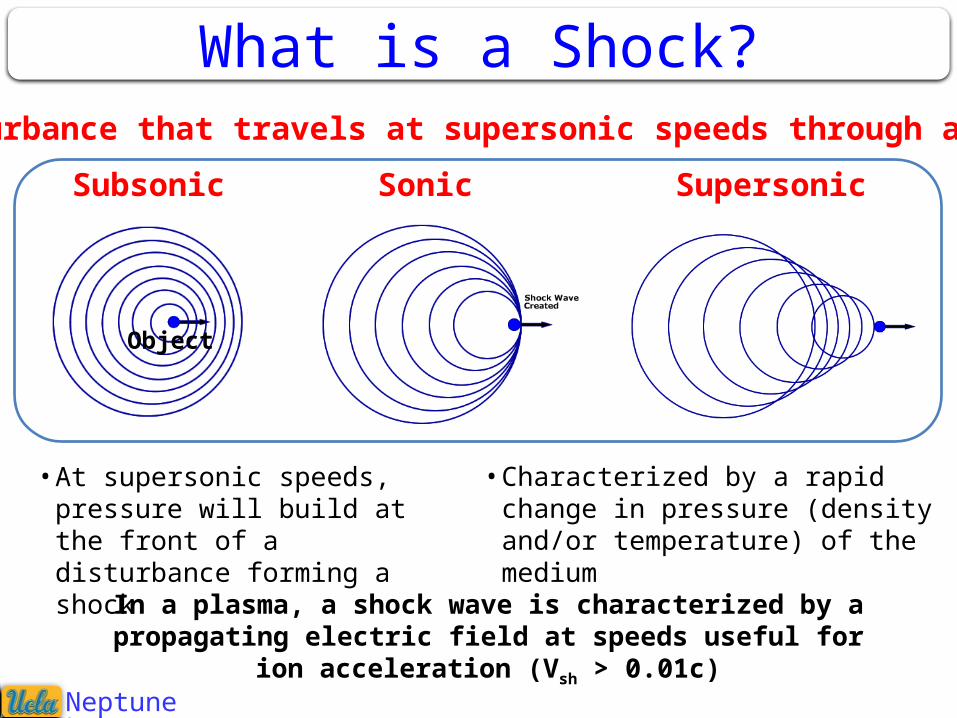
Wake Bow Shock
Bullet at Mach 1.5 through air produces both a wake and a shock
Supersonic Disturbance in a Fluid can Produce both a wake and a shock
DensityCavitation Density Pile up
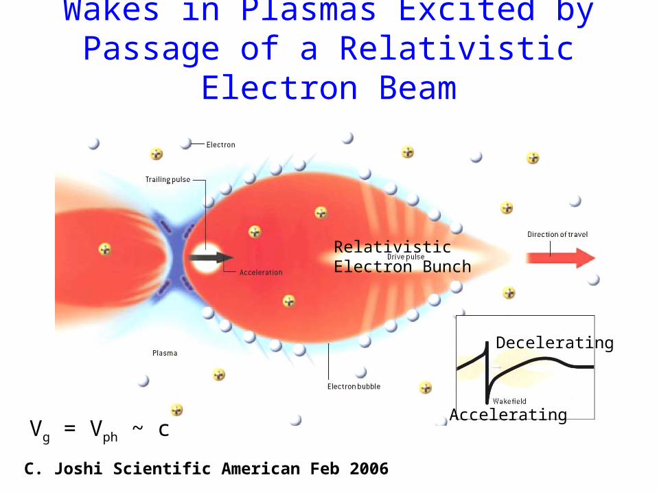
Wakes in Plasmas Excited byPassage of a Relativistic Electron Beam
C. Joshi Scientific American Feb 2006
Vg = Vph ~ c
Relativistic Electron Bunch
Decelerating
Accelerating
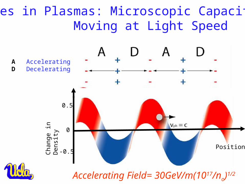
Wakes in Plasmas: Microscopic Capacitors Moving at Light Speed
A AcceleratingD Decelerating
Accelerating Field= 30GeV/m(1017/no)1/2
0.5
Chan
ge in
Den
sity
0
-0.5Position
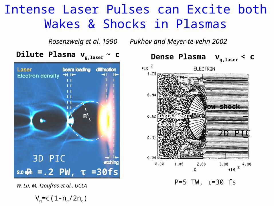
Intense Laser Pulses can Excite both Wakes & Shocks in Plasmas
W. Lu, M. Tzoufras et al., UCLA
P =.2 PW, t =30fs
Rosenzweig et al. 1990 Pukhov and Meyer-te-vehn 2002
Dense Plasma vg,laser < c
2D PIC
3D PIC
Bow shockWakeTurbulent
Plasma
Dilute Plasma vg,laser ~ c
Vg=c(1-ne/2nc)
P=5 TW, τ=30 fs
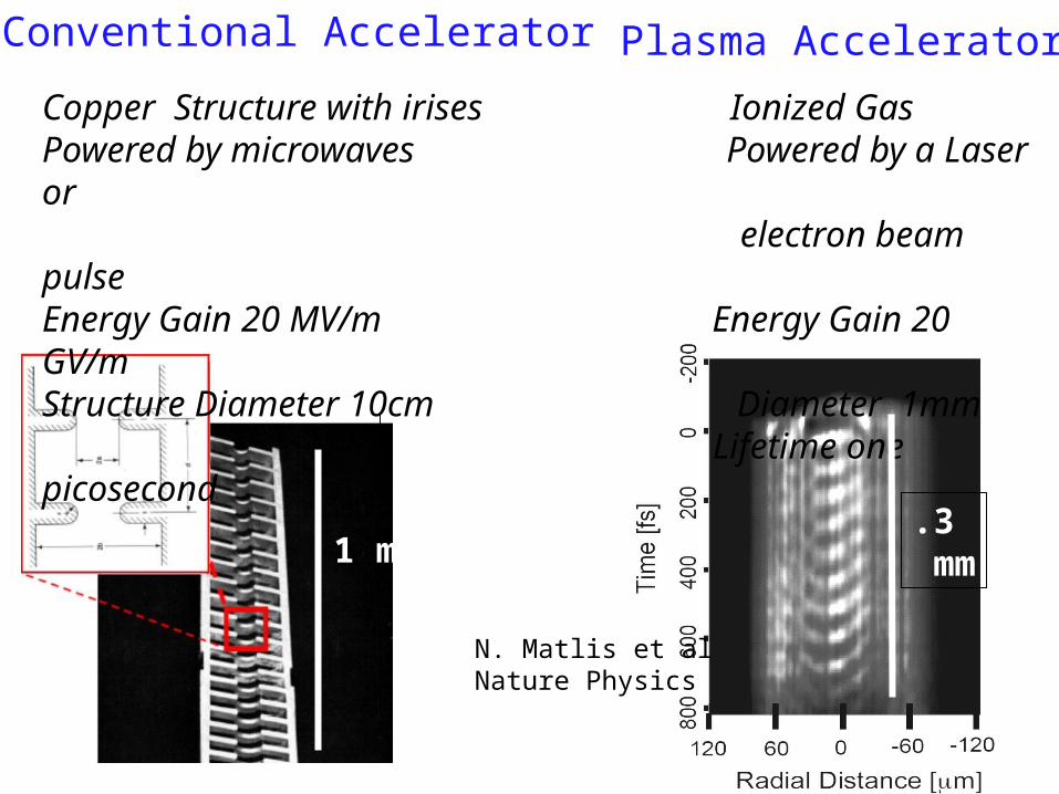
Conventional Accelerator Plasma Accelerator
Copper Structure with irises Ionized GasPowered by microwaves Powered by a Laser or electron beam pulseEnergy Gain 20 MV/m Energy Gain 20 GV/mStructure Diameter 10cm Diameter 1mm Lifetime one picosecond
1 m.3 mm
N. Matlis et alNature Physics
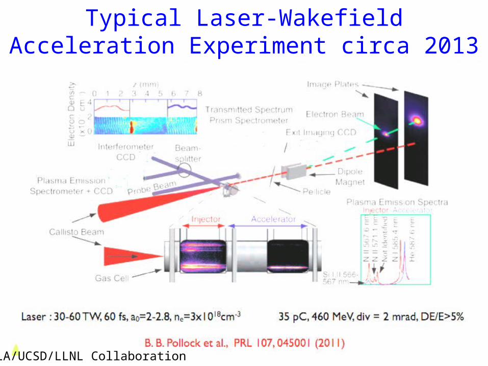
Typical Laser-Wakefield Acceleration Experiment circa 2013
UCLA/UCSD/LLNL Collaboration
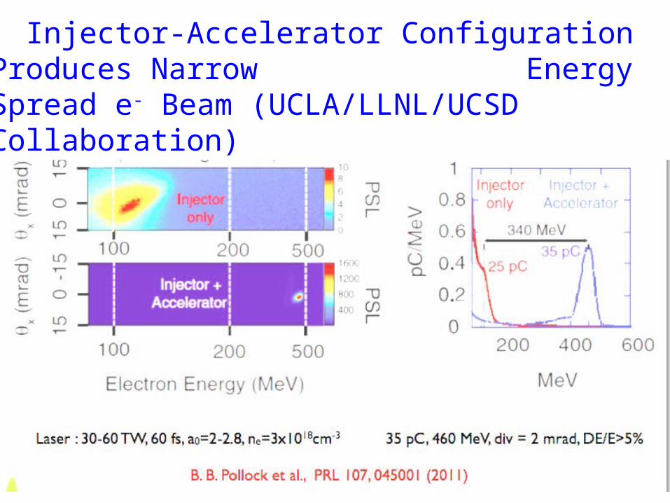
Injector-Accelerator Configuration Produces Narrow Energy Spread e- Beam (UCLA/LLNL/UCSD Collaboration)
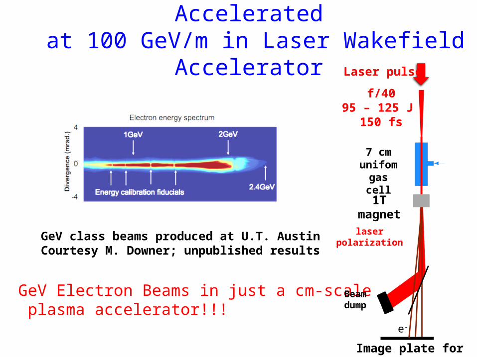
High Quality Electron Beams Accelerated at 100 GeV/m in Laser Wakefield Accelerator
GeV class beams produced at U.T. AustinCourtesy M. Downer; unpublished results
GeV Electron Beams in just a cm-scale plasma accelerator!!!
Image plate for GeV e-
1T magnet
7 cm unifomgas cell
Beam dump
f/4095 – 125 J
150 fs
e-
laserpolarization
Laser pulse
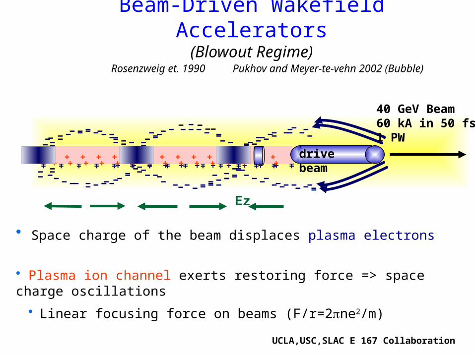
Beam-Driven Wakefield Accelerators(Blowout Regime)
• Plasma ion channel exerts restoring force => space charge oscillations
• Linear focusing force on beams (F/r=2pne2/m)
• Space charge of the beam displaces plasma electrons
Rosenzweig et. 1990 Pukhov and Meyer-te-vehn 2002 (Bubble)
++++++++++++++ ++++++++++++++++
----- --- ----------------
--------------
--------- ----
--- -------------------- - --
---- - -- ---
------ -
- -- ---- - - - - - ------ - -
- - - - --- --
- -- - - - - -
---- - ----
-----
+ + + + + + + + + + ++ + + + + + + + + + + + + + ++ + + + + + + + + + + + + + ++ + + + + + + + + + + + + + +
-
- --
--- --
Ez
drive beam
UCLA,USC,SLAC E 167 Collaboration
40 GeV Beam60 kA in 50 fs1 PW
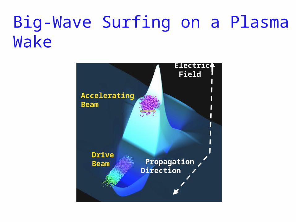
Big-Wave Surfing on a Plasma Wake
Drive Beam
Accelerating Beam
Electric Field
Propagation Direction
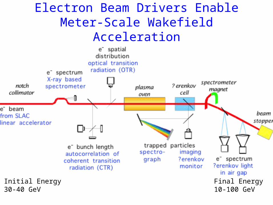
Electron Beam Drivers Enable Meter-Scale Wakefield Acceleration
Initial Energy30-40 GeV
Final Energy10-100 GeV
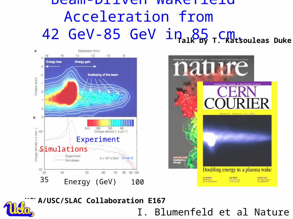
Beam-Driven Wakefield Acceleration from 42 GeV-85 GeV in 85 cm.
I. Blumenfeld et al Nature 2007
Talk by T. Katsouleas Duke UV 445 p741 (2007)
SimulationsExperiment
10035 Energy (GeV)
UCLA/USC/SLAC Collaboration E167
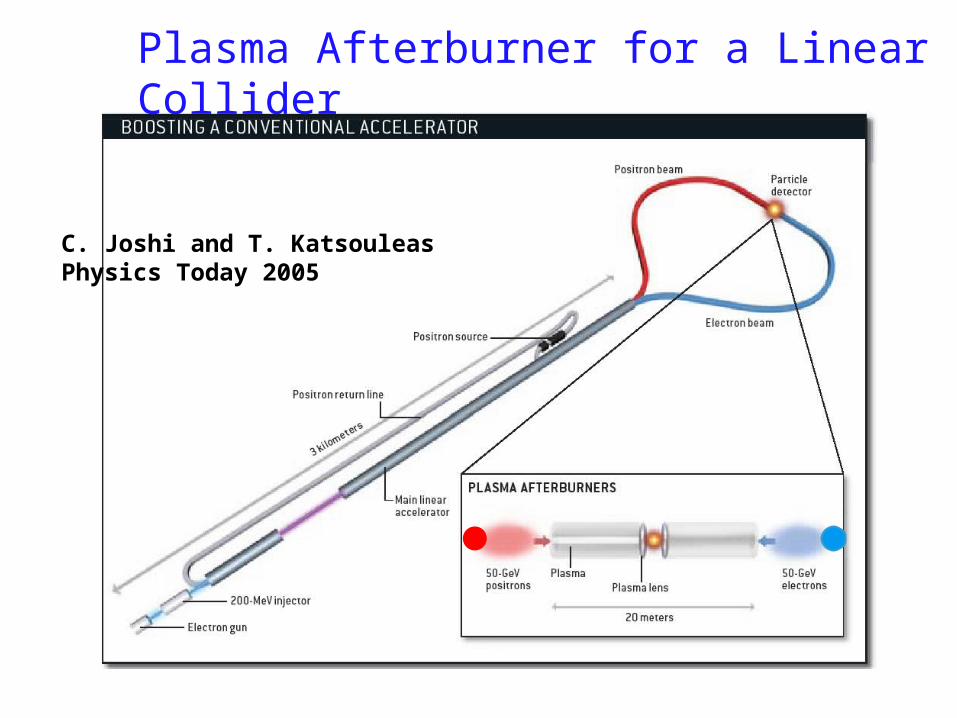
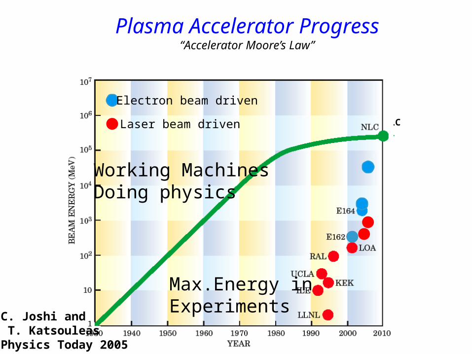
Plasma Afterburner for a Linear Collider
C. Joshi and T. KatsouleasPhysics Today 2005
RAL
LBL Osaka
UCLA
E164X
ILC
ANL
Plasma Accelerator Progress“Accelerator Moore’s Law”
E167
LBNL
Working MachinesDoing physics
Max.Energy inExperiments
Electron beam driven
Laser beam driven
C. Joshi and T. KatsouleasPhysics Today 2005
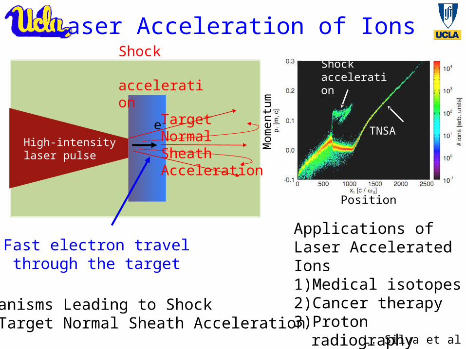
Hot Cold
Shockacceleration
TNSAHigh-intensitylaser pulse
Shock acceleration
TargetNormalSheathAcceleration
Applications of Laser Accelerated Ions1) Medical isotopes2) Cancer therapy3) Proton radiography4) Fast ignition fusion
Fast electron travel through the target
e-
Mechanisms Leading to Shock And Target Normal Sheath Acceleration
L. Silva et al PRL
Laser Acceleration of Ions
Position
Mom
entu
m
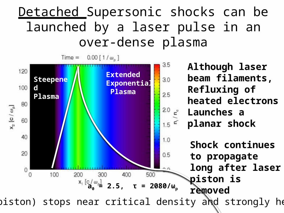
Detached Supersonic shocks can be launched by a laser pulse in an over-dense plasma
SteepenedPlasma
ExtendedExponential Plasma
a0 = 2.5, τ = 2080/ωp
Shock continues to propagate long after laser piston is removed
Although laser beam filaments, Refluxing of heated electronsLaunches a planar shock
Laser Pulse (piston) stops near critical density and strongly heats electrons
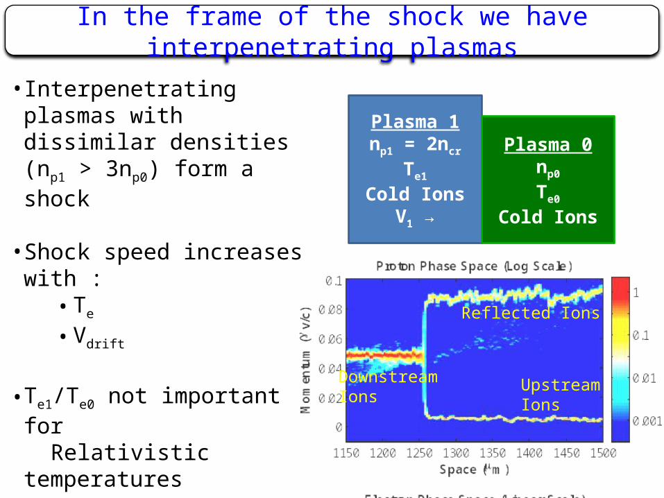
In the frame of the shock we have interpenetrating plasmas
Plasma 1np1 = 2ncr
Te1
Cold IonsV1 →
Plasma 0np0
Te0
Cold Ions
• Interpenetrating plasmas with dissimilar densities (np1 > 3np0) form a shock
• Shock speed increases with :• Te
• Vdrift
• Te1/Te0 not important for Relativistic temperatures
• Vdrift > Vmax shock not formed
• Increasing Vdrift towards Vmax increases the % of reflected protons
UpstreamIons
DownstreamIons
Reflected Ions
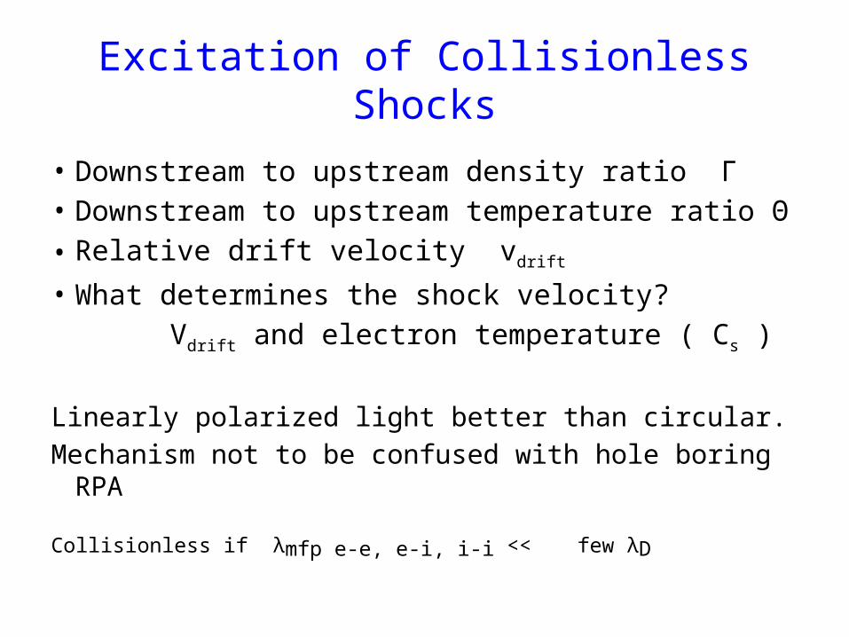
• Downstream to upstream density ratio Γ• Downstream to upstream temperature ratio Θ• Relative drift velocity vdrift
• What determines the shock velocity? Vdrift and electron temperature ( Cs )
Linearly polarized light better than circular.Mechanism not to be confused with hole boring RPA
Collisionless if λmfp e-e, e-i, i-i << few λD
Excitation of Collisionless Shocks
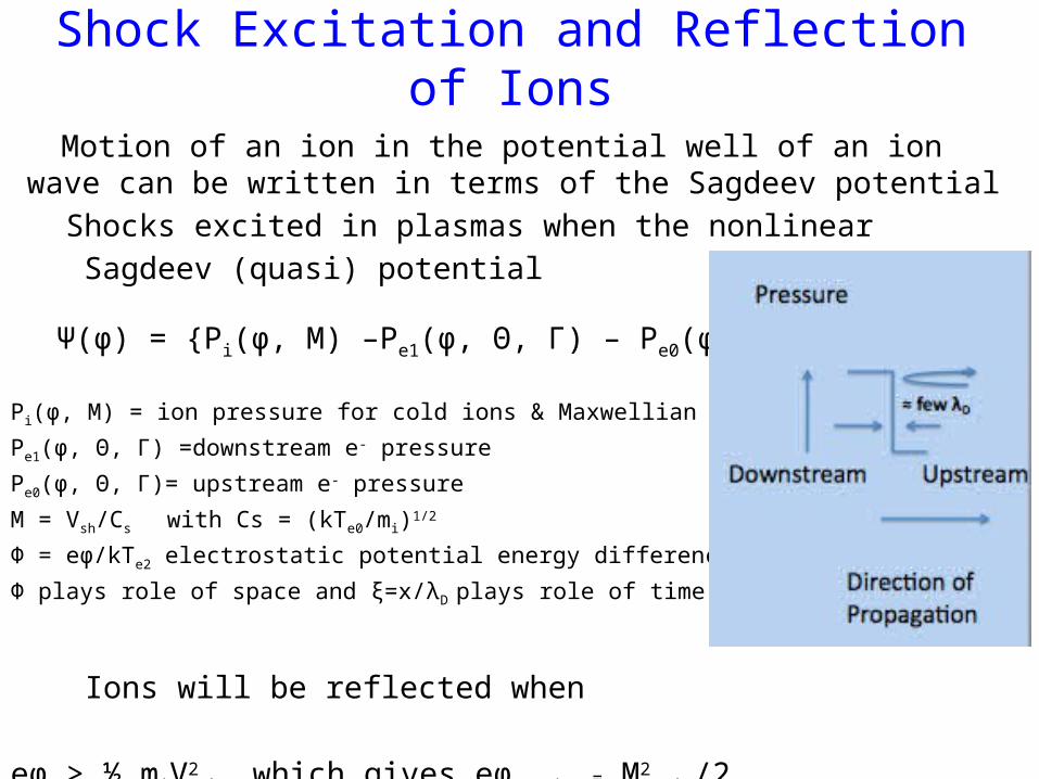
Shock Excitation and Reflection of Ions
Motion of an ion in the potential well of an ion wave can be written in terms of the Sagdeev potential
Shocks excited in plasmas when the nonlinear Sagdeev (quasi) potential
Ψ(φ) = {Pi(φ, M) –Pe1(φ, Θ, Γ) – Pe0(φ, Θ, Γ)} < 0
Pi(φ, M) = ion pressure for cold ions & Maxwellian e-
Pe1(φ, Θ, Γ) =downstream e- pressure
Pe0(φ, Θ, Γ)= upstream e- pressure
M = Vsh/Cs with Cs = (kTe0/mi)1/2
Φ = eφ/kTe2 electrostatic potential energy difference
Φ plays role of space and ξ=x/λD plays role of time
Ions will be reflected when
eϕ > ½ miV2sh which gives eϕ crit = M2
crit/2

Critical Mach Number Needed for Ion Reflection as a Function of Γ and Θ
ExperimentalParameterRegime
Nonrelativistic
Relativistic
PIC simulations
F. Fiuza et al Submitted for publication
1 keV1 MeV1keV1MeV
EXPE
RIM
ENTS
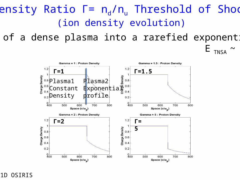
Density Ratio Γ= nd/nu Threshold of Shocks(ion density evolution)
Γ=1 Γ=1.5
Γ=2 Γ=5
Expansion of a dense plasma into a rarefied exponential plasma E TNSA ~ 1/L
1D OSIRIS
Plasma1Constant Density
Plasma2Exponentialprofile
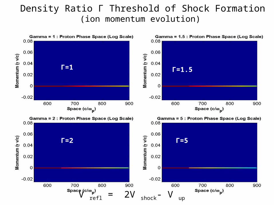
Density Ratio Γ Threshold of Shock Formation(ion momentum evolution)
Γ=1 Γ=1.5
Γ=2 Γ=5
V refl = 2V shock- V up
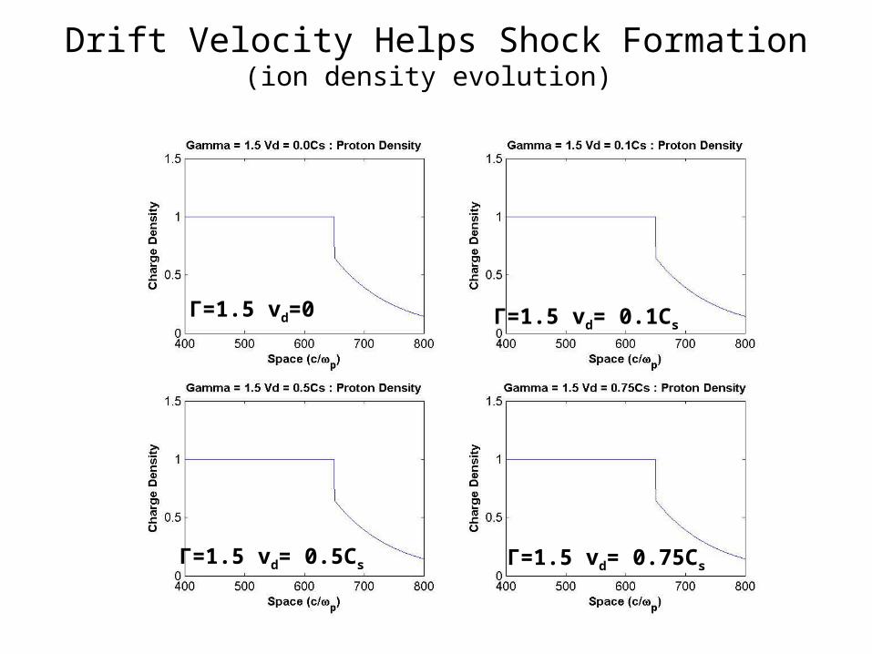
Drift Velocity Helps Shock Formation(ion density evolution)
Γ=1.5 vd=0 Γ=1.5 vd= 0.1Cs
Γ=1.5 vd= 0.5Cs Γ=1.5 vd= 0.75Cs
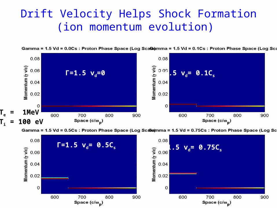
Drift Velocity Helps Shock Formation(ion momentum evolution)
Γ=1.5 vd=0 Γ=1.5 vd= 0.1Cs
Γ=1.5 vd= 0.5Cs Γ=1.5 vd= 0.75Cs
Te = 1MeVTi = 100 eV
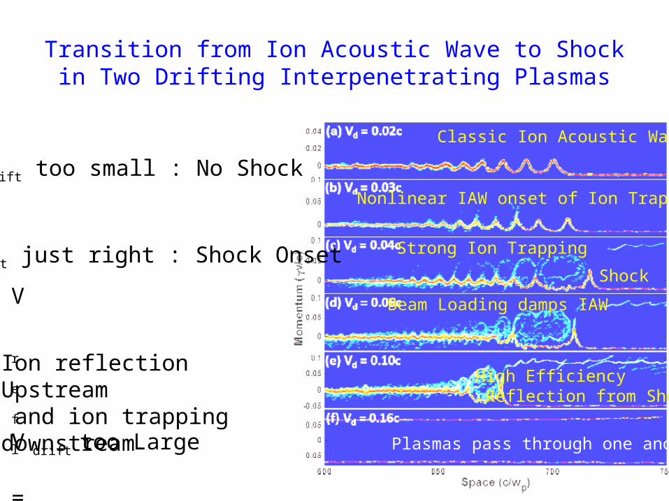
Transition from Ion Acoustic Wave to Shock in Two Drifting Interpenetrating Plasmas
V r
e
f
l = 2V s
h
o
c
k
- V u
p
V drift too small : No Shock
V drift just right : Shock Onset
V drift too Large Plasmas pass through one another
Ion reflection Upstream and ion trapping downstream
Classic Ion Acoustic Wave
Nonlinear IAW onset of Ion Trapping
Shock
Strong Ion Trapping
Beam Loading damps IAW
High Efficiency Reflection from Shock
Formation of Collisionless shocks
• Two interpenetrating plasmas with dissimilar densities and in addition a relative drift expand through one another.
• The sheath field of the higher density plasma which expands with Cs seeds an ion acoustic wave behind it.
• When the conditions of density and drift velocity are right the Sagdeev potential becomes –ve and the nonlinear ion wave morphs into either a soliton (no dissipation) or a shock with ion reflection (upstream) and ion trapping (downstream) acting as the dissipation mechanisms.
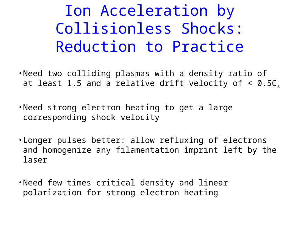
Ion Acceleration by Collisionless Shocks: Reduction to Practice
• Need two colliding plasmas with a density ratio of at least 1.5 and a relative drift velocity of < 0.5Cs
• Need strong electron heating to get a large corresponding shock velocity
• Longer pulses better: allow refluxing of electrons and homogenize any filamentation imprint left by the laser
• Need few times critical density and linear polarization for strong electron heating
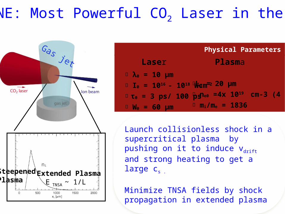
Launch collisionless shock in a supercritical plasma by pushing on it to induce vdrift and strong heating to get a large cs .
Minimize TNSA fields by shock propagation in extended plasma
๏ λ0 = 10 μm๏ I0 = 1016 - 1018 Wcm-2
๏ τ0 = 3 ps/ 100 ps๏ W0 = 60 μm
๏Lg = 20 μm๏ ne0 =4x 10¹⁹
cm-3 (4 nc)๏ mi/me = 1836
Physical Parameters
Laser PlasmaGas jet
hybrid PIC
ni
Extended PlasmaSteepenedPlasma E TNSA ~ 1/L
NEPTUNE: Most Powerful CO2 Laser in the World
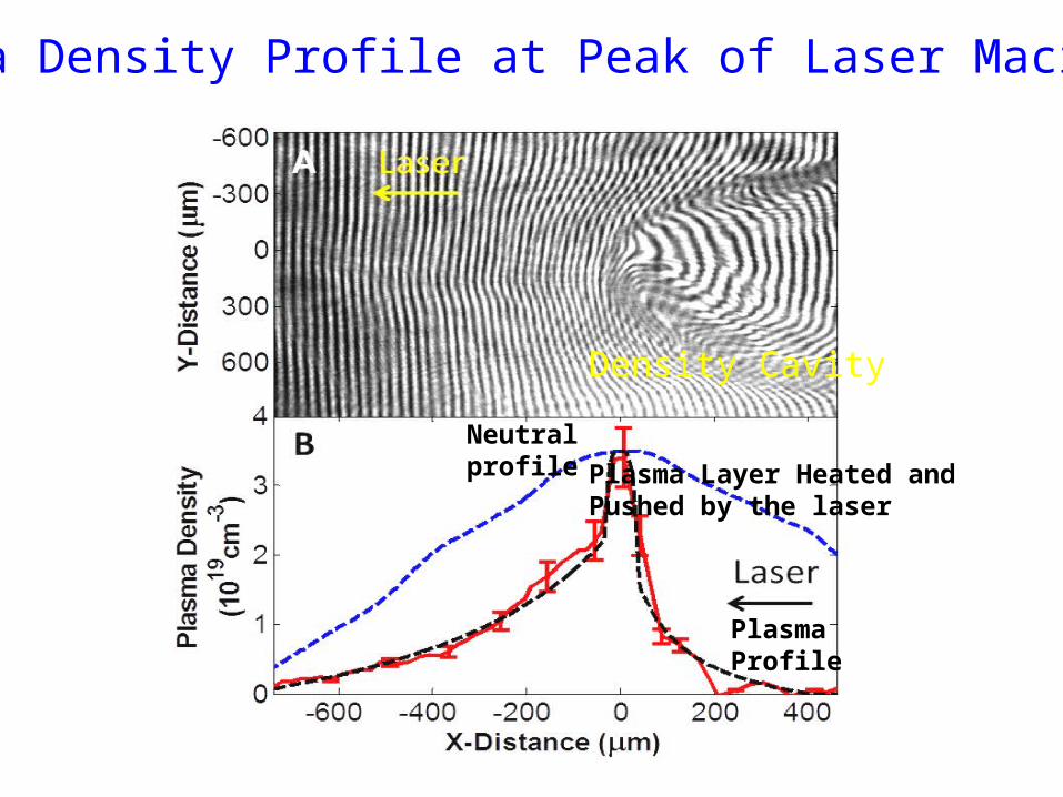
Neutralprofile
Plasma Profile
Plasma Density Profile at Peak of Laser Macropulse
Plasma Layer Heated and Pushed by the laser
Density Cavity
Neptune Laboratory
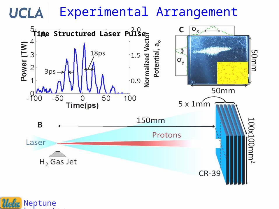
Experimental Arrangement
Time Structured Laser Pulse
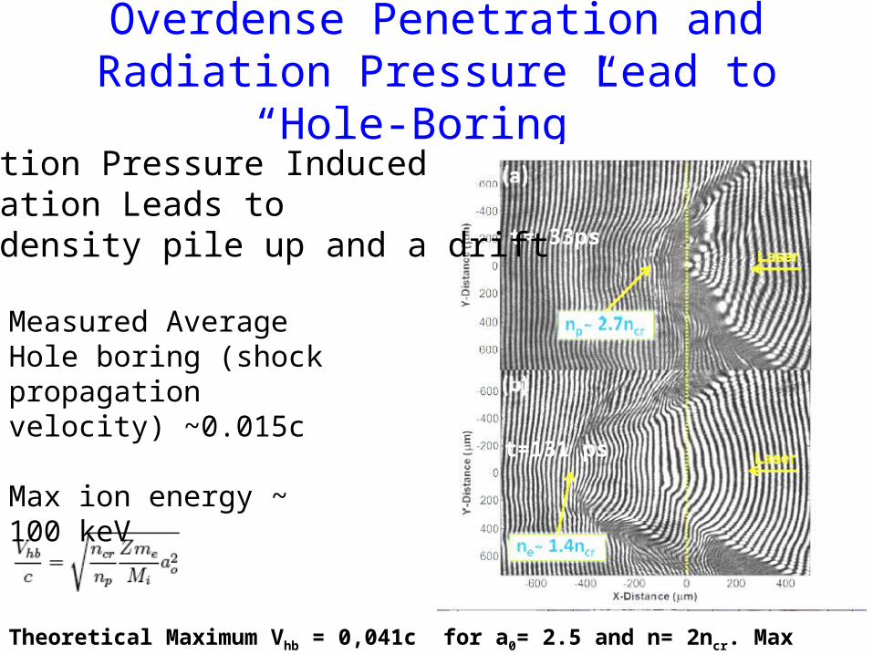
Overdense Penetration and Radiation Pressure Lead to “Hole-Boring”
t= 33ps
t=131 ps
Measured Average Hole boring (shock propagation velocity) ~0.015c
Max ion energy ~ 100 keV
Radiation Pressure Induced Cavitation Leads toBoth density pile up and a drift
Theoretical Maximum Vhb = 0,041c for a0= 2.5 and n= 2ncr. Max Ion Energy = 800 keV
Neptune Laboratory
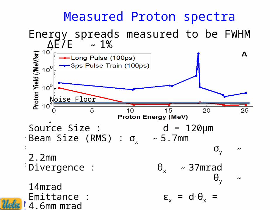
Energy spreads measured to be FWHM ΔE/E 1% :
Measured Proton spectra
Source Size : d = 120µmBeam Size (RMS) : σx 5.7mm : σy 2.2mm :Divergence : θx 37mrad : θy 14mrad :Emittance : εx = d.θx = 4.6mm.mrad εy = d.θy = 1.7mm.mradN ~ 106
Noise Floor
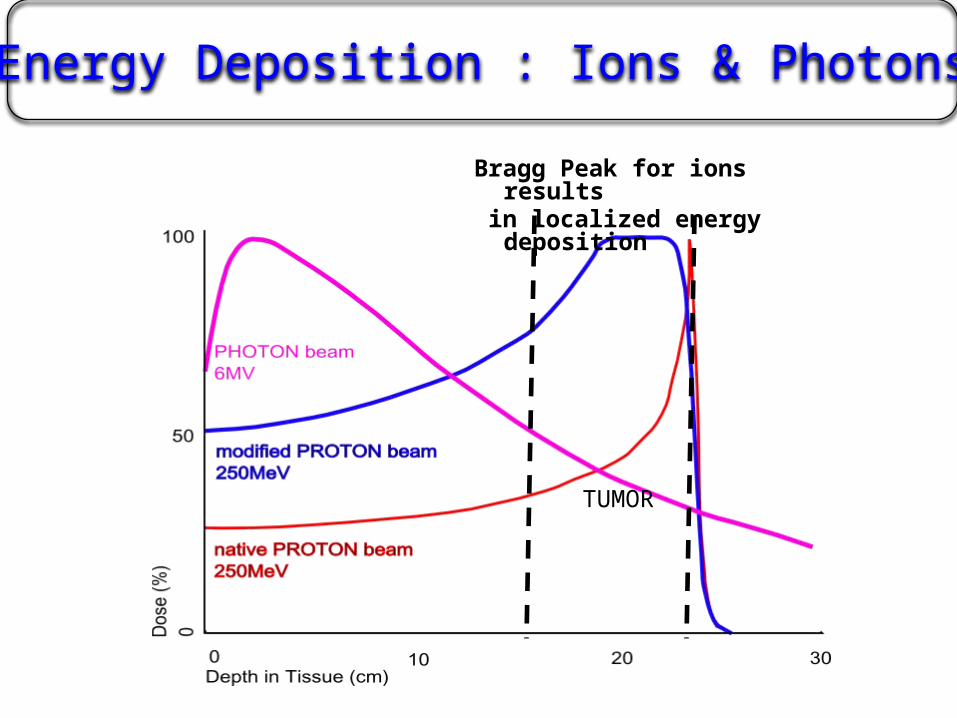
Energy Deposition : Ions & Photons
Bragg Peak for ions results in localized energy deposition
TUMOR
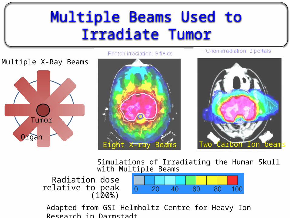
Multiple Beams Used to Irradiate Tumor
Radiation dose relative to peak (100%)
Simulations of Irradiating the Human Skull with Multiple Beams
Adapted from GSI Helmholtz Centre for Heavy Ion Research in Darmstadt
T
Tumor
Organ
Multiple X-Ray Beams
Eight X-ray Beams Two Carbon Ion beams
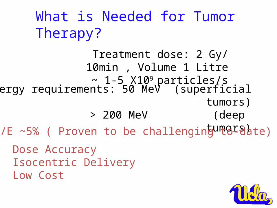
What is Needed for Tumor Therapy?
Treatment dose: 2 Gy/ 10min , Volume 1 Litre ~ 1-5 X10⁹ particles/s
Energy requirements: 50 MeV (superficial tumors) > 200 MeV (deep tumors)
E/E ~5% ( Proven to be challenging to-date)
Dose Accuracy Isocentric DeliveryLow Cost
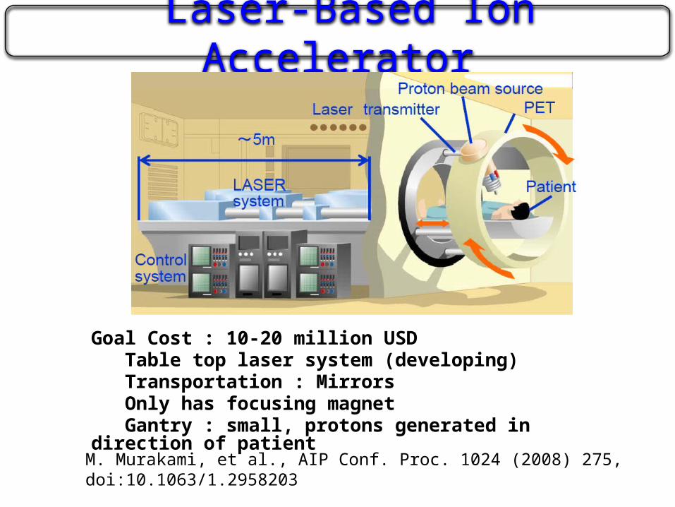
Laser-Based Ion Accelerator
Goal Cost : 10-20 million USDTable top laser system (developing)Transportation : MirrorsOnly has focusing magnet Gantry : small, protons generated in direction of patient
M. Murakami, et al., AIP Conf. Proc. 1024 (2008) 275, doi:10.1063/1.2958203
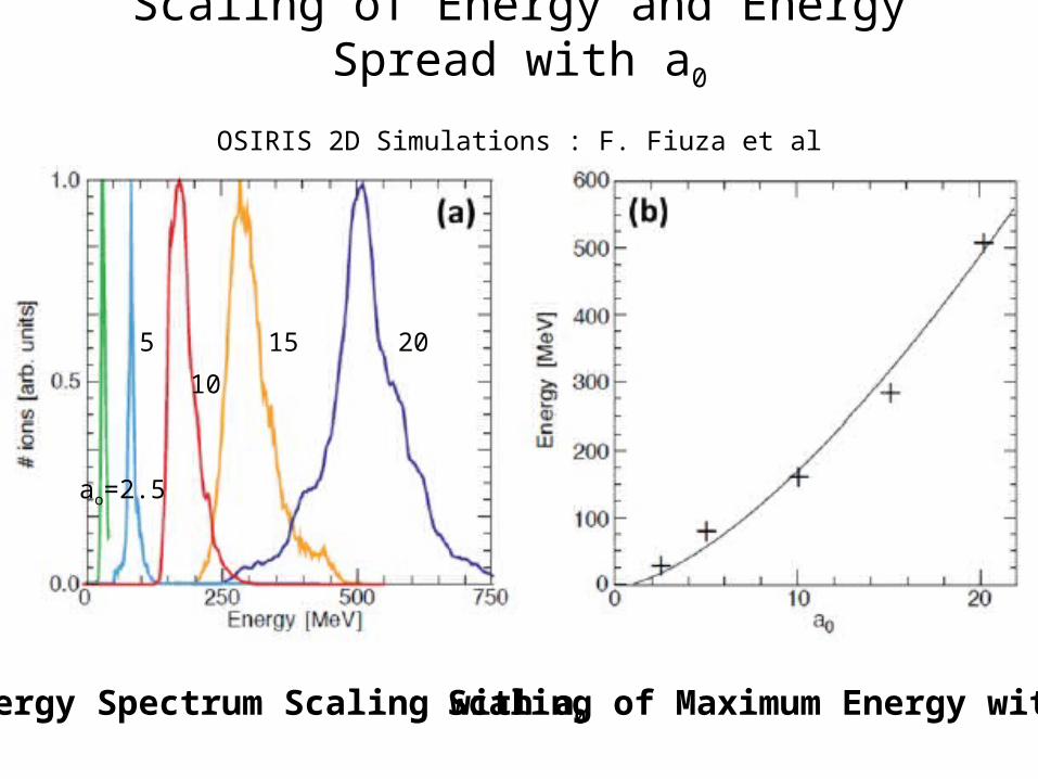
Scaling of Energy and Energy Spread with a0
OSIRIS 2D Simulations : F. Fiuza et al
2015
10
5
ao=2.5
Energy Spectrum Scaling with a0 Scaling of Maximum Energy with a0
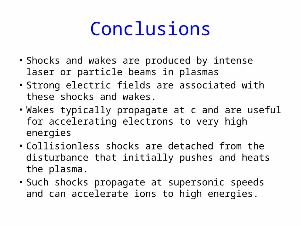
Conclusions
• Shocks and wakes are produced by intense laser or particle beams in plasmas
• Strong electric fields are associated with these shocks and wakes.
• Wakes typically propagate at c and are useful for accelerating electrons to very high energies
• Collisionless shocks are detached from the disturbance that initially pushes and heats the plasma.
• Such shocks propagate at supersonic speeds and can accelerate ions to high energies.
ACKNOWLEDGEMENTS
• All my collaborators at LLNL including B.Pollock, J.Ralph, A. Pak, F. Albert, S. Glenzer, D.Froula (U. Rochester)
• C.Clayton, K. Marsh, D. Haberberger, S. Tochitsky, C.Gong
• F.Fiuza, L. Silva, W.Mori• All my collaborators on E167 experiment at
SLAC• And anyone I may have inadvertently missed.
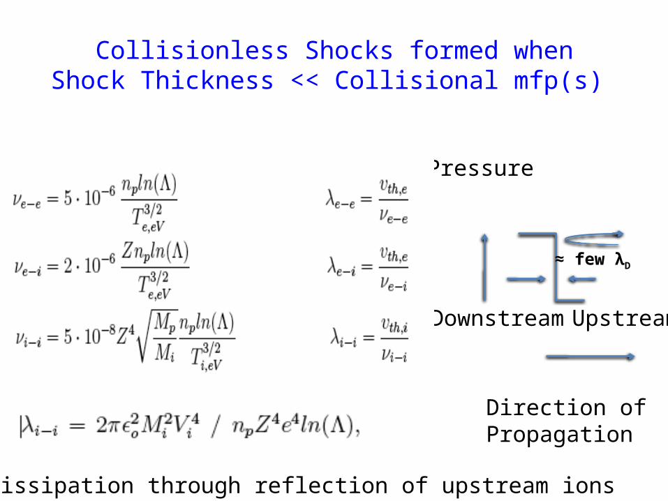
Collisionless Shocks formed whenShock Thickness << Collisional mfp(s)
Pressure
Direction of Propagation
UpstreamDownstream
≈ few λD
Energy Dissipation through reflection of upstream ions
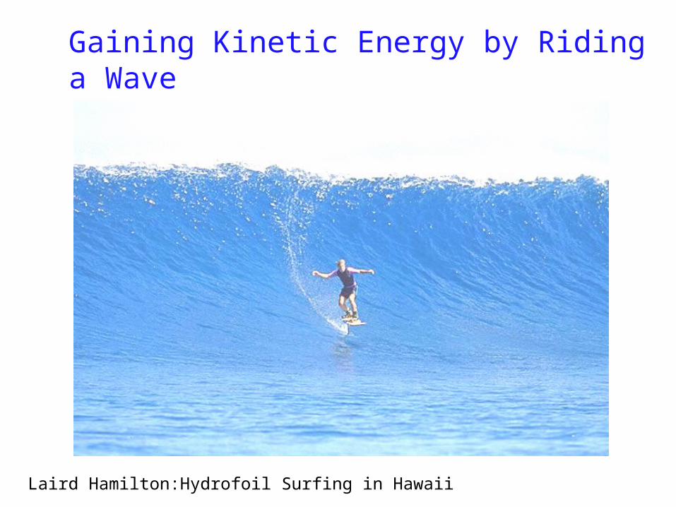
Gaining Kinetic Energy by Riding a Wave
Laird Hamilton:Hydrofoil Surfing in Hawaii