Embed Size (px)
Citation preview
. ...
.
__/ ‘
~’ -- ‘- ;.c.__.. _______
/c.:<~---
, --— .-[
NATIONAL ADVISORY cOMMT~~ $OR AERoNA~~cs . .,2 #
L==’‘L
WAIWIMII lUIIBOIRTORIGINALLY ISUED
January1946 asAdvanceConfidentialReport
WIND-TUNNEL.INVESTIGATIONOF AN NACA66-SERIES
16-EEMENT-THICKIOW-DRAGTKEBREDWIXG
WITHFOWLERAlIllSPLITFIAPS
By RobertH. lieelyandGeraldV. Foster
LangleyMemorialAeronauticalLaboratoryLangleyField,Va.
,-.. ..
~NACA -- z“-”,-
.. /,,.4-’
“ ]~ ACA LE3w~
w’A$l-lltwYl-oNxANGm M3MOWAEF@3Aum’=M
~~fxwTORY@@y mm Va
kJACA WARTIME REPORTS are reprints of papers originally issued to provide rapid distribution ofadvance research results to an authorized group requiring them for the war effort. They were pre-viously held under a security status but me now unclassified. Some of these reports were not tech-nically edited. All have been reproduced without change in order to expedite general distribution.
L- 134
‘,.
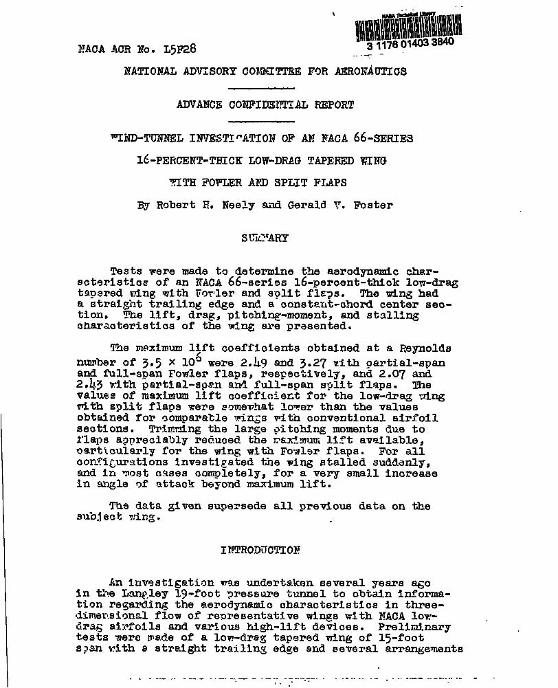
NACA ACR EO. L5F28
NATIONAL ADVISORY COMMITTEE FOR AERONAUTICS
ADVANCE CONFIIZZTIAL REPORT
~i?D-TGNNEL INVESTI”ATIC)NOF AN NACA 66-SERIES
16-PZRCENT-THICK LOW-DRAG TAPERED WING
?!ITHFOPIIERAND SPLIT FLAPS
By Robert H. Neely and Gerald Y. Foster
sL”i’ARY
Tests were made to determine the aerodynamic char-scterlsti.oeof an NACA 66-seriss 16-percent-thiok lore-dragtapered wing with Twler and split flqs. The wing hada stralgiittrailing edge and a oonstmt-ohord center seo-tion. The llft, drag, pitching-mome~t, and stallingcharaoteristios of the wing are prasented.
The meximum l>ft coefficients obtained at a Reynoldsnumber of 3.5 x 10⁵ were 2.L9 and 5.27 vith gartial-spanand full-span Fowler flaps, respectively, and 2.07 and2,45 with partial-sps.nand full-span split flaps. mevalues of maximum lift coefficier.tfor the low-drag tingwith split flaps were scmmwhat lower than the valuesobtatfiedfor comparable wings with conventional airfoilseoti.ons. Trimming the large pitohing moments due tol’lapsappreciably reduced the nsxtmum lit’tavailable,om?ttcularly for the wing with Fovlsm flaps. For alloor.t’i~pratl.onsInvestigated the wing stalled suddenly,and in mat cases completely, for a very small increaseIn angle of attaok beyond maximum lift.
The data given supersede all previous data on thesu”bjectv,?lmg. .
INTRODUCTION
An Investigation was undertaken several years ~oin the Lanp.ley1$1-footgmessure tunnel to obtain informa-tion regarding the aerodynamic characteristics in three-dimerl.sicmelflow of representative wings with NACA low-drag airfoils and various high-lift devices. Preliminary “tests wera ms.deof a low-drag tapered wing of 15-footspan with s straight trailing edge and several arrangements
. . - ..- . . . -- - -. -. — - - .- ---------- . ..-. . . . . - , . . . --- -------- ... - -. ..-.
-. . . . .. —=. - - +—-~-.u~-~a-ka-k . .. ..-J_-< u.-. -.. A. —._#- . . . -------- -.
2 MACA ACR No. L5.-28
of trailing-edge fla?s. A groat deal of difficulty wasencountered In obtalning valid measurements of the ohar-aoteristios primarily because of errors in oorreotionsfor model-support tare and interference and because ofInaoouraoies of the tunnel balances. Some of the datafor the wing with spltt flaps were published In refer-ence 1. Later tests of the same wing (15-foot span) anda smaller but geometrically similar wing (12-foot span)indicated that these data mere In error for the afore-mentioned reasons.
Recently the investigation wss oontinued with testsof the small [12-foot-span) wing to obtatn data under ?mrafavorable test oonditlona, namely, improved tunnel balanossand testing techniques. The w- was tested with partl.al-and full-span arrsn~emnts of O.~0-chord ?owler fla2sand 0.20-chord split Slaps.
Lift, drag, oitcbing-moment, and stalling character-istics are given in the present report. The resultssupersede the data ‘ofreference 1.
CO%?FICTERTS A-NDS~iBOLS
The data presented in this report are given asstandard nondimensional coefficients based on the meanohord and area of the wing with flaps retracted.
CL ()T#
lift coefficient s.
C%laxmaximum lift ooeffioierrt
“%lax“increment of mmchmm lift coefficient measured
from maximum lift coeffioient of wing withflaps retraoted
CD ()drag coefficient ~
% pitching-moment coefficient (*]
where
L
1)
lift
drag
.
.
- —— - ~.—- --.~~.—-- - -- ~~—. . .. . . ..- .. ..
--------- -.-C>.. -:.. r :.”. . . . ......--”.. -.. ; . . .
. .“: .-. , - .“:. ’.. . . . . . .. . . 1. . . . . .
ITACAACR ?~o.‘5’28 ~ 3
M
s
z
~
and
P
v
b
c
5f
a
P.%
]f
IJJ
a
pitching moment about quarter-chordpoint of plain-uing root section
wi~ &r6E
mean chord
free-stream
(sfi)
( Fi)1dynamic pressure ~IL 1
mass density of eir
free-stream velocity
wing &pan
wing-section chord
flap deflection
mgle of attack measured from chord line of rootsection
Reynolds number (p’JF/p)
~~.achnumber (V/a)
coefficient of viscosity
speed of 90und
APPARAT’!RAH) TESTS
Models
the ting equipped with1.
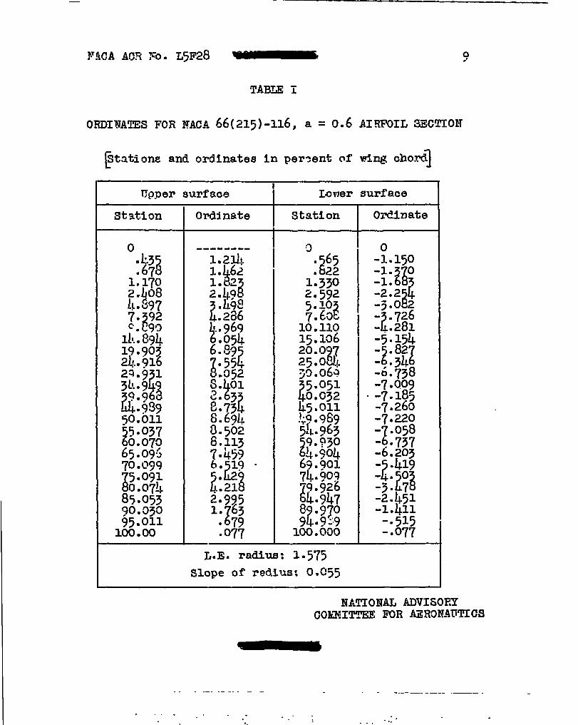
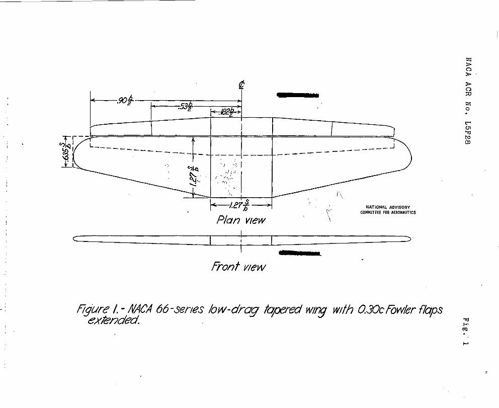
The plain wing was constructed t~ NACA 66(215)-116,a = 0.6 seotions at the root snd to NACA 66(215)-216,a = 0.6 s~ctions at the tin. Ordinates for these airfoilsare given in tables I and II. Straight-line fairings wereused betvmen equal-percentage-chordstations at the rootand tip. me wing pi=. form consists of a square centersectian, outboard seotions havin~ a t~per ratio of 2:1,and elliptical tips. The trsiling edge is strai~t and
... . -. - . . . ... . . . . . . . . . ... . .
4 NACA ACR NO. L5r2G
the le~ding edge is sweptback 12.5°. The #.ng has ageomtri c washout of ls50 between the outboard end ofthe center sectton and the extrene tip; this anglecorresponds to an aerodynamic washout of approximately 0.~?The maximum ordinate of each section along the span liesin the same horizontal plane, so that a small amount ofdihedral is present. The span, area, and aspect ratioare 12 feet, 20.57 square feet, and 7.0, respectively.
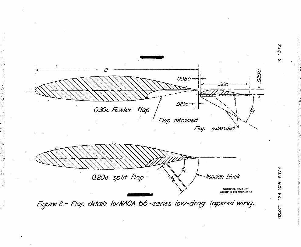
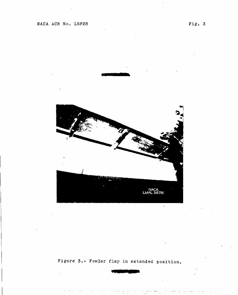
Zhe chord of tha F’owlerflap Is 30 percent of thecorresponding wing chord. The flap was constructed toa G6ttingen 552 airfoil section modified on the lowersurface to fit the ting contour. The ordinates for thisflap me given in table 111. Tbe lower surface of thewing near the trailing edge was cut to the shape of theflag to serve as a retracting well (figs. 2 ati 3). Thenose of the flap was set in the optimum pos:tion formaximum lift as detwmined in an esrlier part of themdn Investigation. (See fig. 2.) Flap deflection isthe angle between the wi~ chofi line and a line throu@the flap trailing e*e tangent to the lower suface. Thedesignation 6f=0 means that the Fowler flap is fullyextended azxlp–aallel to the ving chord line. The partial-.span and full-s?an fla~ arrangements extended over 53 per-cent and 90 percent of the total wing span$ respectively.
?he ohord of the split flap is 20 percent of the100al riq chow. These flaps were attached directly tothe under surface of the wing with the Fowler flapsretracted. Flap deflection is the angle between theunder surface of the wffngand the flap.
The wing and Fowler flaps rere constructed oflaminated mahogany. ~ooth surfaces were obtained byspra@ng the wing and flaps with lacquer and then rubbingin the clhordmisedirection with Eo. 500 Carborundum paper.
Tests
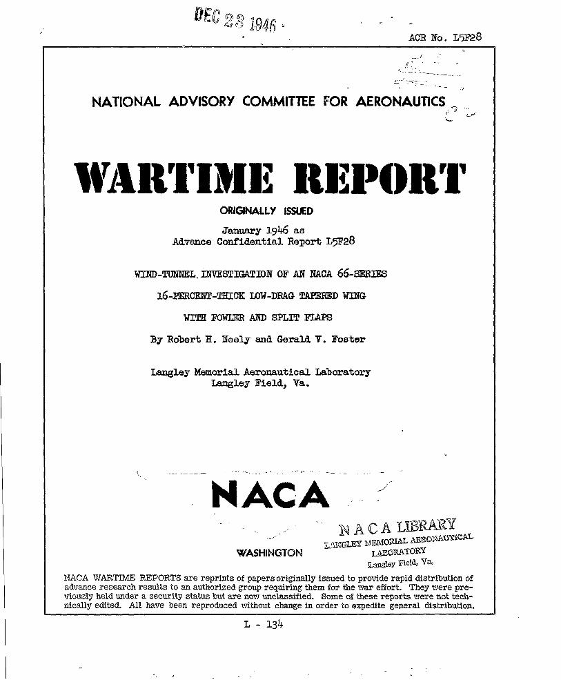
The method of mounting the ving In the test seotionVeasuramgntq ofof the tunnel is *own in figure h.
lift, drag, and ~itchifigmmrent were &ade over a rangeof augle of attack from -4° to beyond the stall. Testswere msde to detemine the ts.reand interference eff’eetsof the model-supporting struts on the wing. m9 stallcharacteristics of the wing-flap sombinetions were determ-ined from visual observations of the behavior of tufts
.
.
NACA ACR NO. L5F28 ~ 5
attaohed to the upper surface of the wing and flap. Notufts were plaoed ahead of the 20-percent-ohord station.
The aerodynamic chamcteristios of the wing wereobtained for the nmst art at a Rqnolds number ofapproximately 3.5 x 10g - a Mach number of 0.13.Mmdmum lift as measured ;t Feynolds numbers ranging
zfrom 2.0 X 10 to 1+.~x 10 for some configurations.For all tests, the air in the tunnel was compressed toan absolute pressure of approtiately 35 pounds persquare inch.
RESCL?S AND DISCUSSION
The data presented herein have been corrected foreffeots of model-support tare and interference and for .air-stream misalinementm
..Jet-boundary correottans have
been applied to the drag coefficient and angle of attaok.
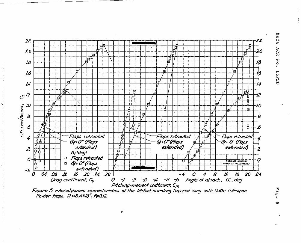
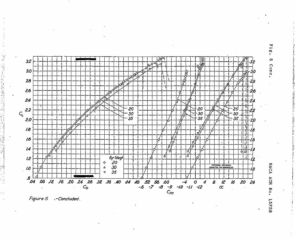
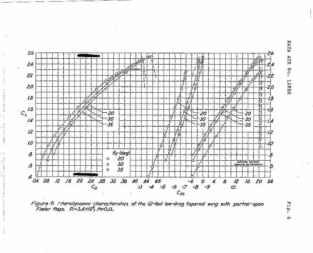
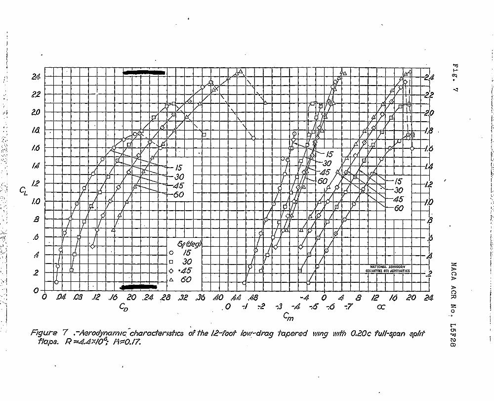
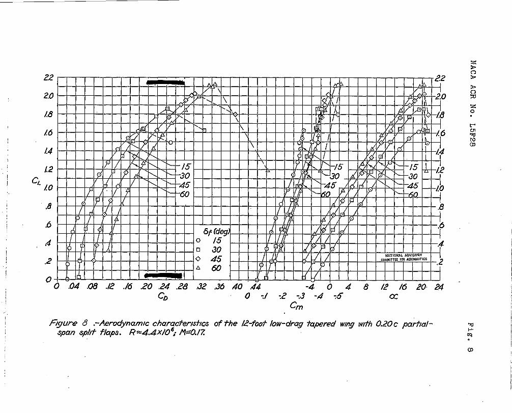
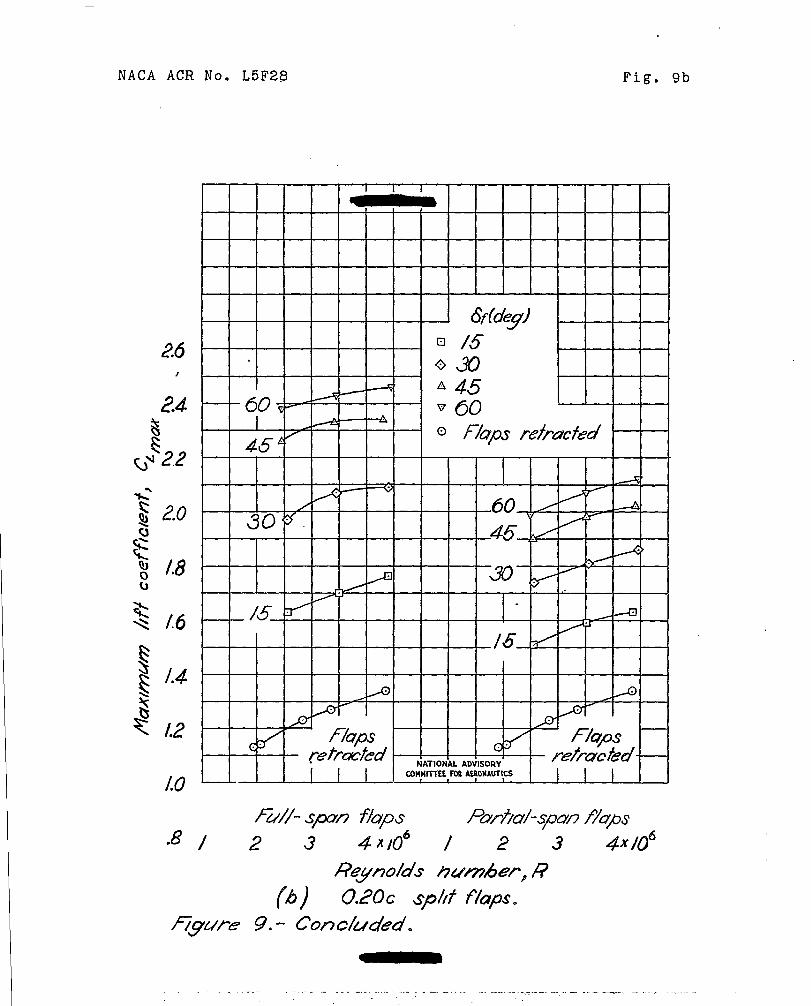
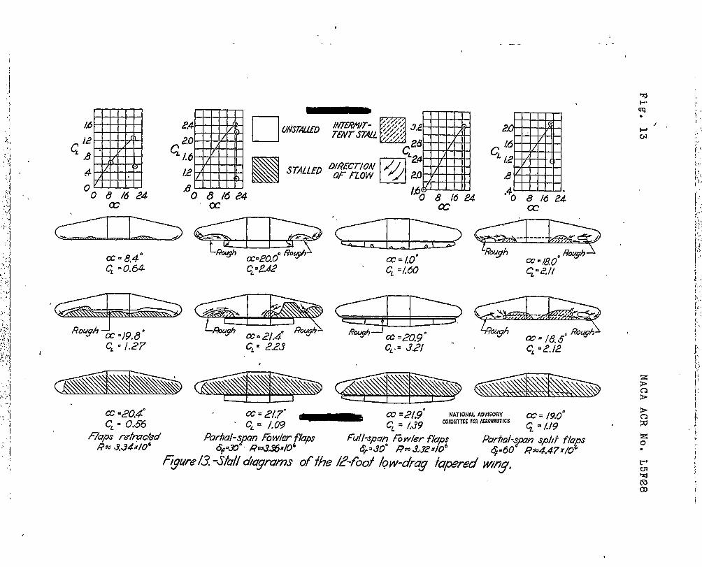
The basic foroe-test data for the wing with Fowlerflaps are given in figuras 5 and 6. me data for theflaps-retracted condition are also given In figure 5.Data for the wing with split flaps are presented infigures 7 and 8. The effects of Reynolds number, flapdeflection, and flap span on maximum lift are shown infl~ures ~, 10, and 11, respectively. The effects ofReynolds number on the llft and pitohing-moment character-lstios of the wing with flaps retraoted are shown Infigure 12. The stall progressions are presented in fig-ure 13.
Lift and pitching-moment characteristics.- Theeffects of Feynolds number on maximum llf~efficientare appreciable as ~om in figure 9. The Increment
‘f c%laxdue to Fowler flaps generally Increased with
Reynolds number but tie Increment due to split flapscha~ed very little.
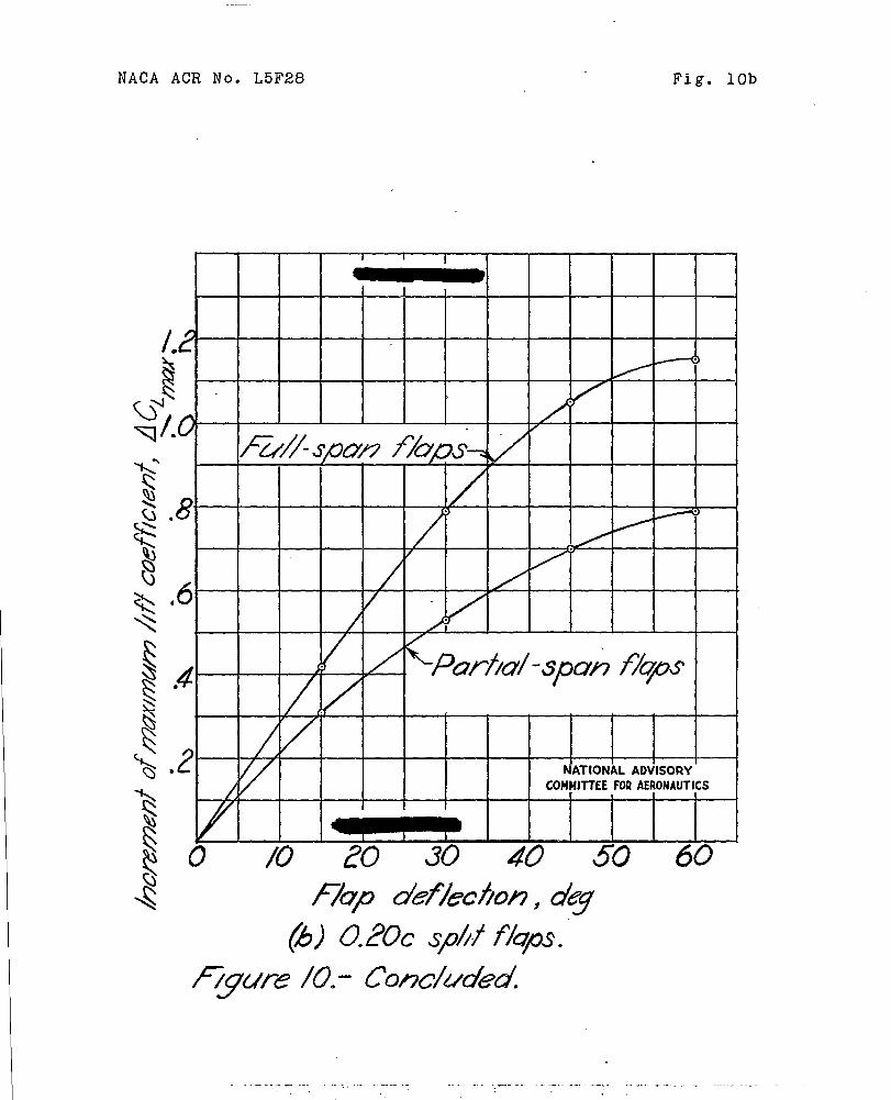
The variations of inzrement of maximum lift withflap deflection shown in figure 10 indicate that the
Joptimun de lectlo~ for the full-span Fowler flap isbatween 3 and 35 . For split flaps it appears thatlittle gain In maximum lift would be obtained fordefleotions grsater than 60°.
..- .- -—. . . .. . . -- .- ----- . . .. .. . - -- --- —------- -.. . —------- ..-— ----- --- .-.— -- . ... .-. .
. . .... ---- .: ... Z---- --.kl- - .- ~G *- ~~-” ~ “ .-”-2 -3.:... -Z>L. .- .-—-A & —---- . . . . . .
.
6
The variation of AC. with
RACA ACR No. L5F2~
flap span is indioated%ax
in figure Il. me increment of maximum lift due to Fowlerflaps-was almost directly proportional to the f’lapspan.For snll.tflaps the increment in lift going from partial-span to full-span flaps was less than that which wouldbe obtained with s llnear increase in lift.
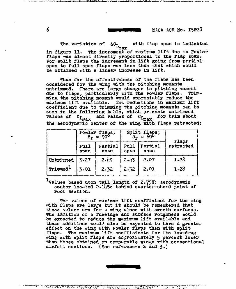
?bus far the effectiveness of the fla?m has beenconsidered for tilewing with the p.itohing~.mentsuntrimmed. There are large ohanges In plt~hin~ momentdue to flaps, ~articularly with the Fowler flaps. Trin-ming the pitohing moment would appreciably reduce themaximum llft available. The reductions In maxlmur liftcoefficient due to trimming the pitcbinL moments oan beseen in the folloving t~ble, which prssents untrimmed
‘alues ‘f C%x ‘d ‘alues ‘f C%mx ‘or ‘rim aboutthe aerodynamic center of the wing with flaps retraoted:
IIInill Partialspan , S?an
Untrimmed 13.27 ! 2.k9
Trimmedl II3.01 2.32
---1i‘y=f & ; i
Flags ‘Fzll lPartlal retracted I
~lal~es based unon tail leruzthof 2.75~: aerodmamlocenter located 0.14.5= befind quart&~chord joint ofroot sectionm
T& values of maxZmum lift coefficient for the wingwith flaps are lar~e but it should be remeubersd thatthese velues are for a wine alone with smooth surfaces.The addition of a fuselage and surface roughness wouldbe exnected to reduce the maximum lift evallable andthese &dtiitlonsWOU1? also be exyected to have a greatereff9ct on the ti.ngwith Fowler flaps than with splitflaps. Tha maximum llft coefficie~ts for the low-dragwin~ wzth split flaps are ap>rozmately 5 percent lowerthan those obtained on comparable wings with conventionalairfoil seotions. (See ref9renc9s Z and 3.)
--—--- - ---.. ..:..: .. _.: .<=.:.,. .:.-+;?.:P. :&s..- . . —.. “,. . .: :;. .. -:--- “-” -. - :. .,.. ..: t --;- P.. ..” ‘. . i <- A.<*..... . .. ...
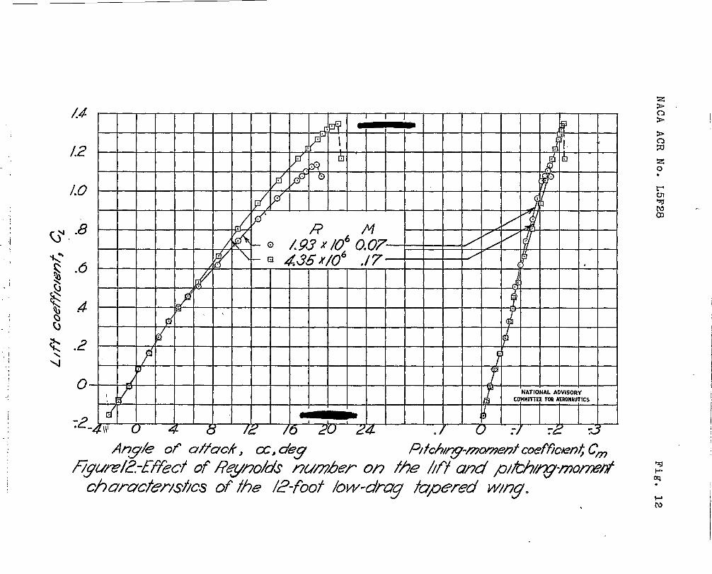
Attention is called to the pecmliar changes inslope of the lift mad pitching-moment curves for theflaps-ratraoted cotiiti.onat low lift coefficients.(See fig. 5. } It IS sl~nifloant that the portion of thecurve with inoreased slope is in the region in whlohlowest profile drag is obtained, Outside this regiona reduction in the slope of the lift curve occurs. Asshown in figure 12, the lift end pitohing-momer~tcumesteml to straighten out with increasing Reynolds number.
Stalllng characteristics.- Diagrams that show theprogression of flow separation are presented in figure 13.pm all configurations, the wing stalled suddenly, andin most caees conmletely, for a swan increase in angleof attack beymd maximum lift. ?.lthflaps retracted orwith partial-s~an split flags there was some indicationof the al~proaohingwing st~..ll;with ~nwlm flaps, however,there was no such lndioatlon.
with flaps retracted, trailing-edge separationbe~an along the entire span at moderate lifts and screadforward to the TO-~ercent chord line at maximum lift.Tlth partial-span split flaps, the complete stall wasprsoed6d by intermittent separation on the center half’of the wing. The flow over the wing outer panels nearthe tra5.lingsdge was very rough for ust angles ofattack.
CONCLUSIONS
Tests in the Langley 1$1-footpressure tunnel of anNACA 66-series 16-percent-thick low-drag tapered wing of12-foot span vlth 0.30-chord Eowler and 0.20-chord splitflaps led to the following conclusions:
1. The maximum lift coefficients obtained with full-spa’iml ~artlal-sban Fowler
~laps ware 3.27 and 2sb.9at
a Reynolds number of 3.5 x 10 . For the same conditions,the maximum lift cosfflcients obtained wtth split flapswere 2.~3 =d 2.Q7a T12evalues of mxim,m lift coeffi-~leiltfor the wing with split flaps were somewhat lower(approxi~atel~ 5 percent) than the values obtained foroomparcble v’ingswith conver~tionalalrfo!l sections.Trimming the large pitching mmnts due to flaps wouldaogrecisbly reduce the msximum lift available, particularlyfor the ?Owler flaps.
.- -. . - . .- . __.. . ._ ._ . . --- - .- _. ----
— —.-. —. . .— —---- ..=. -—— . .. .. ... ...- .”-**. —.-. . .- -- - ._ . _
8 liACAACR i?O. L5F28
2. For all configurations investigated, the wingstalled suddenly, and in most oases completely, for avery small inoreasa in angle of attack beyond maximiunlift. w5th flaps retracted or with partial-span splitflaps, there was some indication of the aparoaohing tingstall; but with partial-span or full-span Fowler flapsthere was no suoh indication.
Langley Memorial Aeronautical LaboratoryNational Advisory Cmmlttee.for Aeronautics
Langley Field, Va.
. REFEREyicEs
1. VUse, Thomas C., and Neely, Robert F.: Find-TunnelInvestigation of an IUUA Low-Drag Tapered Wng withStraight Trailing Edge and Simple Split Flaps.I?ACAACR, Deo. 1941.
2. ??eely,Robert H.: Vhd-1’wmel Tests of Two TaperedWings wit.?.?Straight Trailing Edges and withConstant-Chord Center Seotions of Different Spans.PA5A AI?R,R??ch 19!\3.
3. Neel , Robert E.:&
%lnd+unnel Tests of an NACA-SerZes Taqered ~lz!+with a Straight Trailing
Edge and a Constant-Chord Center Seotion. HACARB NO. 3L13, 19~3.
—
l’!lCAAC?lI@. L5F28 ~ ~
TABTLEi
ORDIWATES FOR NACA 66(215)-116, a = O=6 AIRFOILWc~o~T
~tatione and ordinates in perzent of wing ohofi]
1Upper surface Iav7ersurface
Statlon Ordinate Station Ordinate
o --------
I9
kg3 1.214 .6
:‘73
25-!.l~o
1. 62 ● 22 -1. 01● 170 10 2
i1.330 -1.11
2.908 2.@ 2.5924.d97
-2.2 2
t●h9s 5.ZO
z-~.o?2
~: ;93
.2~6
k
7.63 - .726..969 10● 110 [? ..281
11!● 894 .054 15.1066.t19
:5.15419● 90324.916 1●55” %’g M;
ggj $
.052:. 01
$5.051 -7.009
3
v0.032
;:73 @.oll.-7.185-7.26Q
~o:oll 8.tql~ !;Q.969
z5.037 ;m~g
-7.220
P5[k.963 : :;$
0.07029 ● 930
65.095 p?: !@04 -6.20370.099 . . .
?26 .901
i?
- .4195.091
28z23
7 ● ~o~ -.. 00.07!$ .:2185.053
‘%926$ !33
-3” 72.995 ● -2.)+51
$)0.030z
1. 63z
-1.41195.011
● 79 90 :g:; -.515100● 00 .077 ● -.077
L.E. radius: 1.575
S1OPE!of rsdius: 0.055
NATIONAL ADVISORYCOMI!ITTEEFOR AERONAUTICS
E
.—. .- -. .—-. .. —-—- ____ ___ .
. . . . . ..-, . . . . ..
@
1,
I
.
-———, l––––.J .!) I
J .1/
#- -w/.. w,;
,.
‘J?-/t27# ~
I-—J_——-—-—__-———
/ . .2
,.,r,<-
\!
\
NATIONAL ADVISORY
CDMMITTEE FOR AERONAUTICS
17@m L - YACA66 -series kwv-drag tityxmd wig wjfh 030c/3wkr flipsexfe~ded.
*c1
!=
zo.
0
}
:!i
. ,.1
.;.l
.. . 7i, ,.<,:. ,
. .
,/”
“j ,,
.
C130cFow/er flup.
‘w●
w,\
z>c1>
>c)
ISORY 53ONAUTICS
%o
figure 2.- /77up &fails fbrNACA 66 -series low-drug tapered wing. ~ztoa
t,
I
I
NACA ACR No. L5F28 Fige 3
Figure 3.- Fowler flap in extended position.
. . . .,-,--- ..
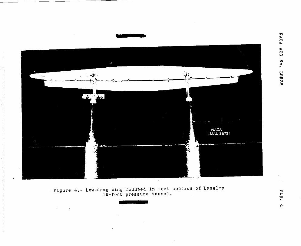
Figure 4,- Low-drag wing mounted in test section of ‘Langley19-foot pressure tunnel.
!2o●
22
t?%)
M
14
.2
0
.
0 .04 .08 ./’2 ./6 .20 .24 .28~ -404812162024Drag coefficient CD O + 72 Y3 + TF T6 Angle of attack, C, a’eg
P)?chmg-moment cvefficrenk Cmfigu~e 5 .-Aeroq’ynamic characteristics of the /2-fmf /ow-drag tapered wIn9WI?%OJOC full-span
Fowler flaps. R*3.4xIO! PKM3.
‘zo●
ul
*
.
\
./‘“(’
,1
‘1~;‘,,‘.(,;.?
. >..4‘.
.,,,
,.. ,,
/
c’
..:
1 [ , .
3,2–J (, I I , ..
II ,1
30
2.6
24
‘2,2
2.0
L8
L6
/.4
lx?
M
“-%4 .00 ./2 ./6 .20 .24 .26 .32 .36.40 94 .48 .s2 ‘!%.60 -4048 !2162024CD -.6 :? -B -.9-10 “k/ -L2 c
C*
f? dl I 11111’
‘%1
L’‘J
m
zo●
Figure 5 .-Concluded.
●
.
c
.2(5
2.4
t I I I I I I I I I I ILL
1 1 1 I
A’&zf I
22
20
M
L6L
0/
-l-t10
.8
.6 A‘v
4
o
EEElii,, !4II
I I J/l I I ,/1 IN&l
vCOHHI1
I I I I I w I I I ITEE FC4 AERONAUTICS
I I I /1 I I I I I I I /1
““,04 .08 ./2 ./6 .20 .24 .28 J2 .36 dO si4 48 -4048/2/62024CD 73 -4 -.5 :6 77 78 -.9 c
cm
F@e 6 .-Aerodynamic characterwlcs of the 12-71w+/ow-drag i+apered wmg wIf-h par+ml-spanFowler flaps. /?*3.4X/05 iV~O,/3.
z0.
t+
~w0)
9
’24
2?2
20
M
~ /2L
Lo
4
.2
0
.
r
\
\
/ ‘ 1/1 \ 1’ \ I
,I a %
- — L — -f
r , , , ,
/ /
d
7 [, 0 “45 ?’ d 4NATIONAL ADVISORY
Cma411m mlAWHAUTICS/ ‘i
A (50i Ar
o .04 .08 ./2 ./5 20 .24 .2(3 .3? .36 .40 .4d .4$ “4b 48/2/62024CD .0 + 3??:3 -.4 %5 ?6 ?7 c
cm
Figure 7 .-Aerodynamic‘chtmtzcterm%csof the L2-foof low-drag tapered wwy WIT%0.20c IW-qxm tphtfkq.os. R =4L4WO:”W=OJZ
%
J’e
.
22 I I I I I I I [ I I I I I I I I I 1 1 I I I 1 [ I 1 I 1 1 1 I I 1 # , I , 22
2.0
4!~! lx 1 I I I I ,, I I I I I !
.8
.6
,4
.s?
(9”
/!/l I I [0 /5
.U
Il-! I 1, II I/ f’
A I I b H?.,
❑ 30.0 45 II 4
i-
i’ T ,“ I [ A
-0 .04 .~ ./2 .16 .20 ,24 .28 .32CD
60
//YPlrl,, F
, , # , I I1 , , I
NAT~ONAL ADVISORY I
IlllolrlllCOWMITTIE ~~ MRoNAuTlcs
.2
Iii(( iii t
.36 40 .44 -4b48/2/62024-0 v’ :2 d -.4 75 c
cm
of the /2-foof low-drag fapered WI179with 0.20 c purfial-1
wP. /w I
e
ICD
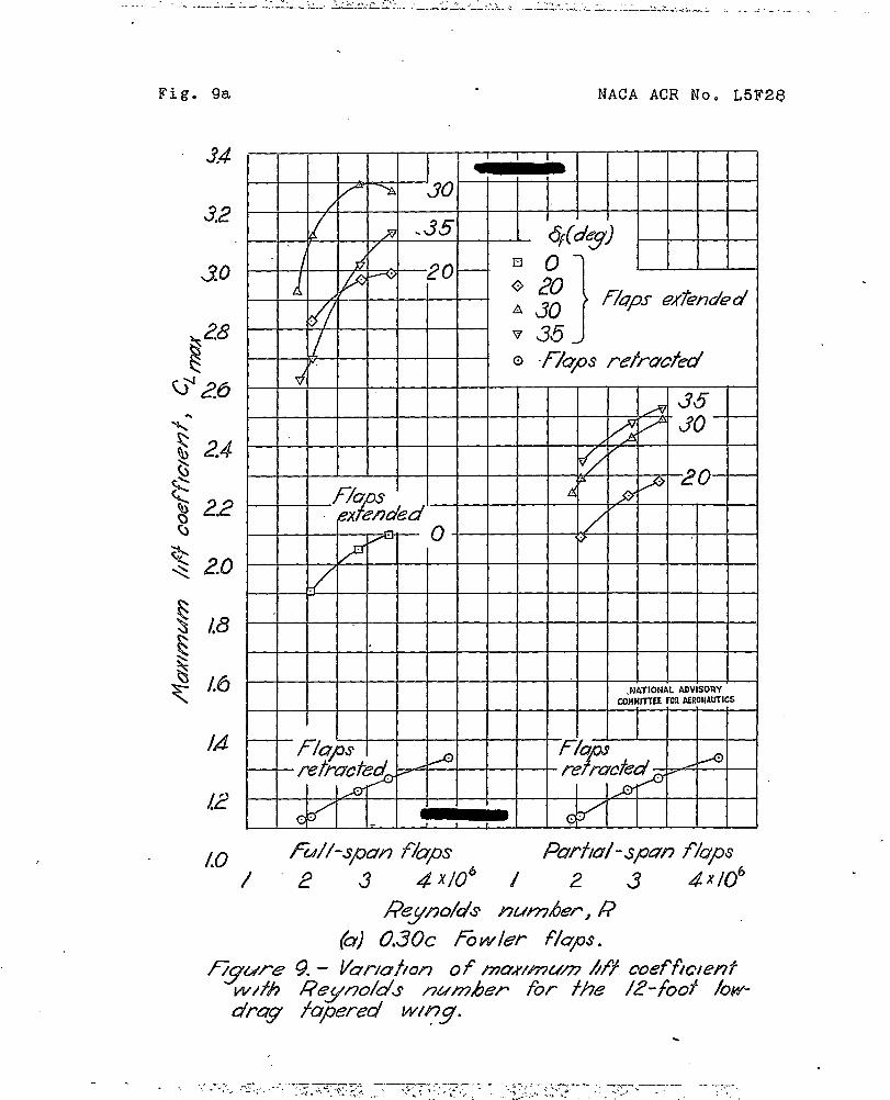
Fig. 9a NACA A(7J7No. L5F2@
34
3.2
$ 2.0
M
L?
I I I I I I I I I 1.WATIONAL ADVISORY
WWIITfEE i(kl AERONAUTICSI 1 1
t
I I I 1 1 I 1 I
I=-l-’
I I 1.1 1- I I 1 I s I 1 I J
10 Fu//-sp7P2 ?5Zps Fkwfd-spon flaps/“
.
9.– V27rz7h7 of tzawnum Af+ coefficientReynolds A44w7heP for +he 12-foof low-Apered wl~g.
.
NACA ACR No. L5F28
26)
24
/.0
Fig. 9b
-. . . . . .. . . . —..- —.— ._—--- . ...-. . ...=.--, -. —.. ..
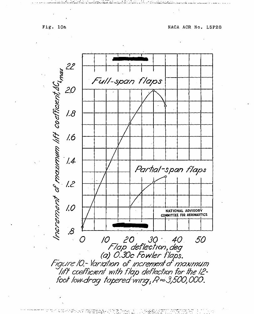
Fig. 10a
.
, \
/00
. 8
NACA ACR No. L5F28
Ir
1 1
I 1 I
,NATIONAL ADVISORY
COMMITTEEFORAERONAUTICS
~ ‘
(2 10 20 30 “ 40 50f/2x2 defkc?icn deu
NACA ACR No. L5F28 Fig. 10b
1 1 I
/2< )
ed/0— — — ~ — — — —.
Fuzzsyzz.n 77’(!OR;-#
.8
/
*6
4 ‘4t
w2 NATIONAL ADVISORY
L ‘/COMMITTEEFORAERONAUTICS
I I I
o /0 20 Jo 40 50 60flujo deflecdofl, U&
@ 0.20C Spht fj+?ps.
F/gure /0.- Co~c/2a(ed
----—.. —..,,- .’
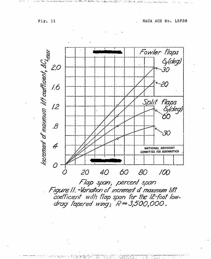
Fig. 11
.
NAC4.ACR ~0, L5F28
&4Q-s (’j–
II - I I fzwi?r?2ps
/ //
I / I .
-’K30//
NATIONAL ADVISORY
/ COMMITTEEFORAERONAUTICS
/27/1 I 1 I I I
0 20 40 60 80 /W
fkp spn, percent span
,!i1
,),,.
44
/.2
/.0
W8 ‘w. )
$- .6G~~ P8
~ .2
/oNATIONAL ADVISORY
COHMITTEE FOR ASliWAIJTICS
%t-m.
I
,
—.
L6
12
.8
4n
24
c 20L/.6
I!2R
“O 8 M 24 ““O 8 /624e E
❑R
uwwzLLfD
STALLED
.
I/ w@ =8.4”
‘Rngh
~ s0,64 ~=2.42
~ -1.27 C,=2.23I,
DIRECTIONof FLOW
cc
w .,● \
;,8,I-JCA
,,
,!
CL I,’f.~.,
\;,
1’.,
m ,,,
cc= m“ 4c
c +04” , ;::~g” ~ e =21.9” NATIONAL ADVISORY a’= /9.0°+ ~
C,= 0.66 ~ =139 cOHUlllEE F02 AEROWTICS. ~ u lf9 ‘ G ;
F/aps ret~chd‘{
R7rhal-syx$ fiwler flap Fu/1-spun t%nder flaps Purhol-s~n sjollt flaps z/?= 3,34d06
i.df”m %R=GUWO’ 4.u30a R* J132x@
o+60 l?=4.47x/o’ .
E@urels -MI. dugrums of fhe 12-foo/ low-drug fqxred wing. [F0w i
I
1
I
.
.
., _ . . ,—~ ~. .. . -.-=?:,- ...--..-=-—-- - . -.. —.. .... .. /-.,, .. ... ,.,
... . . . .... . . .