Embed Size (px)
Citation preview

Housing AuthorityPART C: CONSTRUCTION SPECIFICATION
BCA CLASS 1a, 1b and 10 Single and Grouped Dwellings NATSPEC, May 2016

This reference specification has been developed by NATSPEC in conjunction with the Western Australia Housing Authority. The requirements in this specification are generic and are to be read in conjunction with project specific documents from the Design consultant, including drawings, schedules and appendices. It does not cover the requirements for every project situation.
The Design consultants’ documents take precedence over this reference specification. Check the consultants’ documents for any variations to the requirements of this specification.
Copyright
The copyright for this document remains with NATSPEC and the Western Australia Housing Authority. All specifiers who make use of this document must be current NATSPEC subscribers.
PREFACE
This reference specification has been developed for use on all housing projects by the Western Australia Housing Authority of the appropriate BCA class. It includes framed construction (steel and timber), masonry veneer and full masonry construction. It may include requirements which are not applicable to the project. Read this specification in conjunction with other project specific documents, including drawings, schedules and appendices, and refer/conform to the applicable requirements.

Western Australia Housing Authority Specification
WA Housing specification – BCA Class 1a, 1b & 10 buildings i April 2016
TABLE OF CONTENTS
Table of contents ............................................................................................................................................................................. i 0131 Preliminaries .......................................................................................................................................................................... 1 0171 General requirements ........................................................................................................................................................... 3 0184 Termite management ............................................................................................................................................................ 5 0201 Demolition .............................................................................................................................................................................. 6 0221 Site preparation ..................................................................................................................................................................... 7 0222 Earthwork ............................................................................................................................................................................... 7 0223 Service trenching .................................................................................................................................................................. 9 0241 Landscape – walling and edging ......................................................................................................................................... 9 0242 Landscape – fences and barriers ...................................................................................................................................... 10 0250 Landscape – gardening ...................................................................................................................................................... 11 0271 Pavement base and subbase ............................................................................................................................................. 13 0274 Concrete pavement ............................................................................................................................................................. 14 0276 Paving – sand bed ............................................................................................................................................................... 15 0310 Concrete ............................................................................................................................................................................... 16 0331 Brick and block construction ............................................................................................................................................. 19 0342 Light steel framing .............................................................................................................................................................. 22 0382 Light timber framing............................................................................................................................................................ 24 0383 Sheet flooring and decking ................................................................................................................................................ 26 0411 Waterproofing - external and tanking ................................................................................................................................ 27 0421 Roofing ................................................................................................................................................................................. 28 0431 Cladding ............................................................................................................................................................................... 30 0451 Windows and glazed doors ................................................................................................................................................ 31 0453 Doors and access panels ................................................................................................................................................... 32 0454 Overhead doors ................................................................................................................................................................... 34 0455 Door hardware ..................................................................................................................................................................... 34 0467 Glass components .............................................................................................................................................................. 35 0471 Thermal insulation and pliable membranes ..................................................................................................................... 36 0511 Lining .................................................................................................................................................................................... 38 0551 Joinery .................................................................................................................................................................................. 39 0572 Miscellaneous fixtures and appliances ............................................................................................................................. 41 0574 Window coverings ............................................................................................................................................................... 41 0611 Rendering and plastering ................................................................................................................................................... 42 0612 Cementitious toppings........................................................................................................................................................ 44 0621 Waterproofing - wet areas .................................................................................................................................................. 46 0631 Ceramic tiling ....................................................................................................................................................................... 47 0651 Resilient finishes ................................................................................................................................................................. 49 0652 Carpets ................................................................................................................................................................................. 50 0654 Engineered panel floors...................................................................................................................................................... 51 0655 Timber flooring .................................................................................................................................................................... 52 0656 Floor sanding and finishing ............................................................................................................................................... 53 0671 Painting ................................................................................................................................................................................ 54 0702 Mechanical design and install ............................................................................................................................................ 56 0802 Hydraulic design and install ............................................................................................................................................... 58 0902 Electrical design and install ............................................................................................................................................... 61 Referenced documents ................................................................................................................................................................ 64

Western Australia Housing Authority Specification
WA Housing specification – BCA Class 1a, 1b & 10 buildings 1 April 2016
0131 PRELIMINARIES
1 GENERAL
1.1 THE SITE
Occupied premises General: For the parts of the site designated as an occupied premise, conform to the following:
- Allow occupants to continue in secure possession and occupancy of the premises for the required period.
- Maintain safe access for occupants.
- Arrange work to minimise nuisance to occupants and for their safety.
- Protect occupants against weather, dust, dirt, water or other nuisance, by such means as temporary screens.
Proposals: Submit details of proposed methods.
- Purpose of submission: Information only.
Protection of persons and property Temporary works: Provide and maintain required hoardings, barricades, guards, fencing, shoring, temporary roadways, footpaths, signs, lighting, watching and traffic flagging.
Accessways, services: Do not obstruct or damage roadways and footpaths, drains and watercourses and other existing services in use on or adjacent to the site. Determine the location of such services.
Property: Do not interfere with or damage property which is to remain on or adjacent to the site, including adjoining property encroaching onto the site, and trees.
Rectification Accessways, services: Rectify immediately any obstruction or damage to roadways and footpaths, drains and watercourses and other existing services in use on or adjacent to the site. Provide temporary services whilst repairs are carried out.
Property: Rectify immediately any interference or damage to property which is to remain on or adjacent to the site, including adjoining property encroaching onto the site, and trees.
Existing services Service to be continued: Repair, divert or relocate service, as documented.
Trenches: If the existing service crosses the line of a required trench, or will lose support when the trench is excavated, provide permanent support for the existing service.
Redundant services: Remove redundant parts, and make safe.
Interruption to services: Minimise the number and duration of interruptions.
Proposals: Submit proposals for action to be taken to existing services before starting this work.
- Purpose of submission: For review.
Adjoining property Notice: At least 10 working days before commencing work, submit to owners and occupants of adjoining property written notice of intention to commence work and an outline description of the type and extent of work.
Revealed encroachments: If the works reveal unknown encroachments of adjoining property on to the site or of existing site structures on to adjoining property, immediately seek instructions.
Records: For properties which may be affected adversely by the works, carry out the following:
- Inspect the properties with the contract administrator and owners and occupants of the properties, before commencement of work.
- Make detailed records of conditions existing within the properties, especially structural defects and other damage or defacement.
- Arrange for at least 2 copies of each record, including drawings, written descriptions, and photographs, to be endorsed by the owners and occupants, or their representatives, as evidence of conditions existing before commencement of work.
Endorsed copies: Submit one endorsed copy of each record. Keep the other endorsed copy on site.
- Purpose of submission: Information only.
1.2 CONSTRUCTION PLANT
Parking Principal’s existing parking areas: Use only designated parking areas.
Use of existing services General: Existing services may be used as temporary services for the performance of the contract subject to conditions of use as documented.
Protective clothing Protective clothing: Make available protective clothing for the use of visitors.
- Safety helmets: To AS/NZS 1801, Type 1.
- Certification: Required.
. Certification provider: An organisation accredited by the Joint Accreditation System of Australia and New Zealand (JAS-ANZ).
Project signboards General: Provide project-specific signboards and the following:
- Locate where directed.
- Maintain in good condition for duration of the work.
- Obtain permission for removal.
- Remove on completion.
1.3 BUILDING THE WORKS
Survey marks Definition: A survey peg, bench mark, reference mark, signal, alignment, level mark or any other mark used or intended to be used for the purpose of setting out, checking or measuring the work.
Care of survey marks: Preserve and maintain the principal’s survey marks in their true positions.
Rectification: If survey marks are disturbed or obliterated, immediately rectify.
Materials Requirement: All materials must be new, unless documented otherwise.
Safety Accidents: Promptly notify the architect of the occurrence of the following:
- Accidents involving death or personal injury.
- Accidents involving loss of time.
- Incidents with accident potential such as equipment failure, slides and cave-ins.
Accident reports: Submit reports of accidents.
- Purpose of submission: Information only.
Contractor's representative General: Must be accessible, and fluent in English and technical terminology.

Western Australia Housing Authority Specification
WA Housing specification – BCA Class 1a, 1b & 10 buildings 2 April 2016
Subcontracting General: Submit a complete list of proposed subcontractors and suppliers.
Items supplied by the principal General: Unload and take delivery of them, inspect them for defects and then take care of them. If defects are found, advise. Return unused items to the principal.
1.4 COMPLETION OF THE WORKS
Final cleaning General: Before the date for practical completion, clean throughout, including interior and exterior surfaces exposed to view. Vacuum carpeted and soft surfaces. Clean debris from the site, roofs, gutters, downpipes and drainage systems. Remove waste and surplus materials.
Samples: Remove non-incorporated samples, prototypes and sample panels.
Reinstatement General: Before the date for practical completion, clean and repair damage caused by installation or use of temporary work and restore existing facilities used during construction to original condition.
Adjoining property Evaluation: At practical completion, inspect the properties, originally identified as possibly adversely affected by the works, with the contract administrator, owners and occupants of the properties, recording any damage that has occurred since the pre-commencement inspection.
Pest eradication General: Employ suitably qualified pest exterminators. At practical completion submit a certificate stating that completed works are free of pest types as documented.
Removal of plant General: Within 10 working days after practical completion, remove temporary works and construction plant no longer required. Remove the balance before the end of the defects liability period.
1.5 MISCELLANEOUS
Contractor and principal to observe confidentiality Publicity: Do not issue information concerning the project for publication in the media without prior written approval of the principal. Refer to the principal, enquiries from the media concerning the project.
Compliance with the law Requirements of authorities: The principal, before entering into the contract, has given the notices, paid the fees, and obtained the permits, approvals and other authorisations, as documented.
Graffiti removal Plant and equipment: Make sure all plant and equipment, including temporary offices and lunch rooms, are free of graffiti.
Removal: Remove any graffiti applied to buildings, plant and equipment.
Failure to remove: If graffiti is not removed within the time nominated by the contract administrator, the Housing Authority will remove the graffiti and recover the cost from the contract.
Water Corporation approved sub-meter General: Provide Water Corporation approved sub-meters. Conform to Water Corporation 20 mm and 25 mm meter – Requirements/layout. (See www.watercorporation.com.au)
Inspection: Once water meter is installed, conform to the following:
- Arrange for inspection by the Water Corporation to verify compliance and acceptance of payment for takeover.
- Complete the Water Corporation Application and Agreement Form, selecting Option 1 for individual metering of multiple unit developments (3 or more
dwelling units) and pay all application costs. These forms can be obtained from the Water Corporation.
Verification: Submit a copy of the payment receipt for the application and registration of the meters as confirmation that sub-meters have been accepted by the Water Corporation. The fees will be reimbursed to the contractor on receipt of proof of payment.

Western Australia Housing Authority Specification
WA Housing specification – BCA Class 1a, 1b & 10 buildings 3 April 2016
0171 GENERAL REQUIREMENTS
1 GENERAL
1.1 APPLICABILITY
General Requirement: Conform to 171 General requirements, as appropriate, in all worksections.
1.2 PERFORMANCE
Structural design actions Standard: To the AS/NZS 1170 series and AS 4055 as appropriate.
1.3 STANDARDS
Current editions General: Use referenced Australian or other standards (including amendments), and the BCA including state and territory variations which are current three months before the date of the contract except where other editions or amendments are required by statutory authorities. Any local authority requirements take precedence.
1.4 INTERPRETATION
Definitions General: For the purposes of this document the definitions given below apply:
- Contractor: Means the same as builder.
- Documented: Documented, as documented and similar terms mean contained in the contract documents.
- Hot-dip galvanized: Zinc coated to AS/NZS 4680 after fabrication with coating thickness and mass to AS/NZS 4680 Table 1.
- Metallic-coated: Steel coated with zinc or aluminium-zinc alloy as follows:
. Metallic-coated steel sheet: To AS 1397. Metal thicknesses specified are based metal thicknesses.
. Ferrous open sections zinc coated an in-line process: To AS/NZS 4791.
. Ferrous hollow sections zinc coated by a continuous or specialised process: To AS/NZS 4792.
- Northern areas: Sites located north of 27° latitude.
- Principal: Principal has the same meaning as owner, client and proprietor and is the party to whom the contractor is legally bound to construct the works.
- Professional engineer: As defined by the BCA.
- Proprietary: Identifiable by naming the manufacturer, supplier, installer, trade name, brand name, catalogue or reference number.
- Provide: Provide and similar expressions mean supply and install and include development of the design beyond that documented.
- Required: Required by the contract documents, the local council or statutory authorities.
- Supply: Supply, furnish and similar expressions mean supply only.
1.5 BUSHFIRE PROTECTION
General Conformance: In areas designated as bushfire prone, comply with statutory and local authority requirements.
Standard: To AS 3959 in conjunction with SAA HB 330.
2 PRODUCTS
2.1 GENERAL
Manufacturers’ or suppliers’ recommendations General: Provide and select, if no selection is given, transport, deliver, store, handle, protect, finish, adjust and prepare for use the manufactured items in accordance with the current written recommendations and instructions of the manufacturer or supplier.
Proprietary items/systems/assemblies: Assemble, install or fix to substrate in accordance with the current written recommendations and instructions of the manufacturer or supplier.
Sealed containers General: If materials or products are supplied by the manufacturer in closed or sealed containers or packages, bring the material or products to point of use in the original containers or packages.
Substitution Identified proprietary items: Identification of a proprietary item does not necessarily imply exclusive preference for the identified item, but indicates the necessary properties of the item.
Alternatives: If alternatives to the documented products, methods or systems are proposed, submit sufficient information to permit evaluation of the proposed alternatives.
2.2 TIMBER
Moisture content General: Make milled products from timbers seasoned as follows:
- To within 3% of the equilibrium moisture content appropriate to the timber and its intended conditions of use.
- With no more than 3% difference between any 2 pieces in any one group.
Acclimatisation General: Acclimatise timber fitouts by stacking them for two weeks in the in-service conditions with air circulation to all surfaces after the following are complete:
- Air conditioning operational.
- Lighting operational.
- Site drainage and stormwater works are complete.
- Space fully enclosed and secure.
- Wet work complete and dry.
Unseasoned timber General: If unseasoned timber is provided, or variation in moisture content is likely, make allowance for shrinkage, swelling and differential movement.
Recycled timber Grit blasted or re-machined: Remove all nails and screws.
Classification: Visually graded.
Durability General: Provide timbers with natural durability appropriate to the conditions of use or preservative-treated timbers of equivalent durability.
Natural durability class of heartwood: To AS 5604.
Preservative treatment: To the AS 1604 series.
Minimum requirement: To the Natural and treated timber durability table.

Western Australia Housing Authority Specification
WA Housing specification – BCA Class 1a, 1b & 10 buildings 4 April 2016
Natural and treated timber durability table
Exposure Natural timber Treated timber Remarks
Required durability class to AS 5604
Required hazard class to the AS 1604 series
Inside, above ground. Completely protected from the weather. Well ventilated
Class 4 H1 Treated timber resistant to lyctids. Untreated timber must be protected from termites
Inside, above ground. Protected from wetting with nil leaching. Well ventilated
Class 3 H2 Treated timber resistant to borers and termites. Untreated timber must be protected with a finish
Above ground, exposed to weather. Periodic moderate wetting and leaching
Class 2 H3 Treated timber resistant to borers, termites and moderate decay. Applicable to weatherboards, fascias, pergolas (above ground), window joinery, framing and decking
In-ground Class 1 H4 (Severe wetting and leaching)
Treated timber resistant to borers, termites and severe decay. Applicable to fence posts, greenhouses, pergolas (in-ground) and landscaping timbers
H5 (Extreme wetting and leaching and/or critical uses.)
Applicable to retaining walls, piling, house stumps, building poles, cooling tower fill
2.3 STEEL
Durability General: Provide steel products protected from corrosion to suit the conditions of use.
Internal engineer designed steel members: Remove mill scale, rust, moisture and oil. Coat with a zinc phosphate primer to the manufacturer’s instructions.
Built-in products below damp proof course: Stainless steel 316 or engineered polymer.
Corrosion resistance General: Conform to the following atmospheric corrosivity category as defined in AS 4312 and the AS/NZS 2312 series.
Compliance: Conform to the Corrosion resistance table or provide proprietary products with metallic and/or organic coatings of equivalent corrosion resistance.
Corrosion resistance table
Atmospheric corrosivity category to AS 4312
Heavy steel members including lintels more than 3.2 mm thick
Steel cladding, lining, trims and flashings
C1 and C2 (Low) Galvanize after fabrication 600 g/m2
Metallic-coated sheet AZ150
C3 (Medium) Galvanize after fabrication 600 g/m2
Metallic-coated sheet AZ200
C4 and T (High) Stainless steel 316 or 316L or galvanize after fabrication 600 g/m2 plus organic coating
Metallic-coated sheet AZ200 plus organic coating
Preparation and pre-treatment Standard: To the AS 1627 series.
Galvanizing General: Galvanize mild steel components (including fasteners) to AS 1214, AS 1397 or AS/NZS 4680, as appropriate, and in the following conditions:
- Exposed to weather.
- Embedded in masonry.
- Exposed to or in air spaces behind external leaves of masonry walls.
- In contact with chemically treated timber.
2.4 PROTECTIVE COATINGS
General Environment: To AS/NZS 2312.1 clause 2.3.
Coating designation: To AS/NZS 2312.1 Table 6.3.
CCA (copper chrome arsenic) treated timber Greasing: Before placing bolts or other metal components in contact with CCA-treated timber, paint contact surfaces or coat in grease or a bituminous coating.
Unseasoned timber General: Do not fix in contact with steel framing without fully painting the contact surfaces of timber and steel.
2.5 FASTENERS
Self-drilling screws Standard: To AS 3566.1.
2.6 VAPOUR BARRIER
General Vapour barrier to slabs: To AS 2870 clause 5.3.3.
Minimum thickness: 0.2 mm.
3 EXECUTION
3.1 WALL CHASING
Holes and chases General: Make holes and chases required in masonry walls so that the structural integrity of the wall is maintained. Do not chase walls nominated as fire or acoustic rated.
Parallel chases or recesses on opposite faces of a wall: Not closer than 600 mm to each other.
Chasing in blockwork: Chase only core-filled hollow blocks or solid blocks not designated as structural.
Concrete blockwork chasing table
Block thickness (mm) Maximum depth of chase (mm)
190 35
140 25
90 20

Western Australia Housing Authority Specification
WA Housing specification – BCA Class 1a, 1b & 10 buildings 5 April 2016
3.2 FIXING
General Suitability: If equipment is not suitable for fixing to non-structural building elements, fix directly to structure and trim around penetrations in non-structural elements.
Fasteners Sufficiency: Use proprietary fasteners capable of transmitting the loads imposed, and sufficient for the rigidity of the assembly.
3.3 FOOTPATH CROSSING
General Requirement: Provide a footpath and kerb crossing to local authority requirements.
3.4 COMPLETION
General Removal of temporary work, services and plant: Remove temporary work services and construction plant within 10 working days after occupation of the works.
Final cleaning: Remove rubbish and surplus material from the site and clean the works throughout including interior and exterior surfaces exposed to view. Vacuum clean carpeted and soft surfaces. Clean debris from the site, roofs, gutters, downpipes and drainage systems.
Samples: Remove non-incorporated samples, sample panels and prototypes.
Warranties: Register with manufacturers, as necessary, and provide copies of manufacturers’ warranties.
Instruction manuals: Provide the manufacturers’ instruction manuals.
Operation: Make sure moving parts operate safely and smoothly.
Surveyor’s certificate: Provide a certificate which confirms that the work, including boundary fences, has been correctly located.
Services layout: Provide a plan which shows the location of underground services.
Authorities’ approvals: Provide evidence of approval of the local authority or principal accredited certifier and statutory authorities whose requirements apply to the work.
Keys: Provide two keys for each set of locks keyed alike and two keys for each lock keyed to differ.
0184 TERMITE MANAGEMENT GROH
1 GENERAL
1.1 STANDARDS GROH
General Standard: To AS 3660.1.
Chemical soil barriers – reticulation systems Type testing: To AS 3660.3 Section 5.
Termite management system notice Requirement: Permanently fix a durable notice in a prominent location to BCA 3.1.3.4 Appendix A.

Western Australia Housing Authority Specification
WA Housing specification – BCA Class 1a, 1b & 10 buildings 6 April 2016
0201 DEMOLITION
1 GENERAL
1.1 STANDARDS
Demolition Standard: To AS 2601.
1.2 SUBMISSIONS
Records Dilapidation record: Submit a copy of the dilapidation record for inspection. Submit to each owner of each adjacent property a copy of the part of the record relating to that property and obtain their written agreement to the contents of the record, before commencement of demolition.
1.3 ASBESTOS REMOVAL
General Transport and disposal cost: Pay for all costs of removing the asbestos waste.
Verification: Where asbestos products are found and removal required, submit written evidence of asbestos waste disposal at a waste facility licensed to accept asbestos.
2 PRODUCTS
2.1 DEMOLISHED MATERIALS
General Removal: Except for items to be recovered for re-use in the works, or delivery to the owner and materials to be recycled in the works, take possession of demolished materials and remove them from the site. Do not burn or bury demolished materials on the site. Prevent spillage of demolished materials in transit.
Recycling: Where possible, dismantle building components for off-site recycling.
3 EXECUTION
3.1 SUPPORT
Temporary support Existing buildings: Until permanent support is provided, provide temporary support for sections of existing buildings which are to be altered and which rely for support on work to be demolished.
3.2 PROTECTION
Encroachment General: Prevent the encroachment of demolished materials onto adjoining property, including public places.
Weather protection General: If walls or roofs are opened for alterations and additions, or the surfaces of adjoining buildings are exposed, provide temporary covers to prevent water penetration. Provide covers to protect existing plant equipment and materials intended for re-use.
Security General: If walls or roofs are opened for alterations or additions, provide security against unauthorised entry to the building.
3.3 DEMOLITION
Dilapidation record Purpose: Use the dilapidation record to assess the damage and rectification work arising out of demolition work.
Hazardous materials removal Standard: To AS 2601 clause 1.6.2.
Notice of completion General: Give at least 7 working days' notice of completion of demolition so that adjacent structures may be inspected following completion of demolition.
Rectification: Repair any damage arising out of demolition work. Obtain written acceptance from the owner of each adjoining property of the completeness and standard of the rectification work.
Western Australia Housing Authority Specification
WA Housing specification – BCA Class 1a, 1b & 10 buildings 7 April 2016
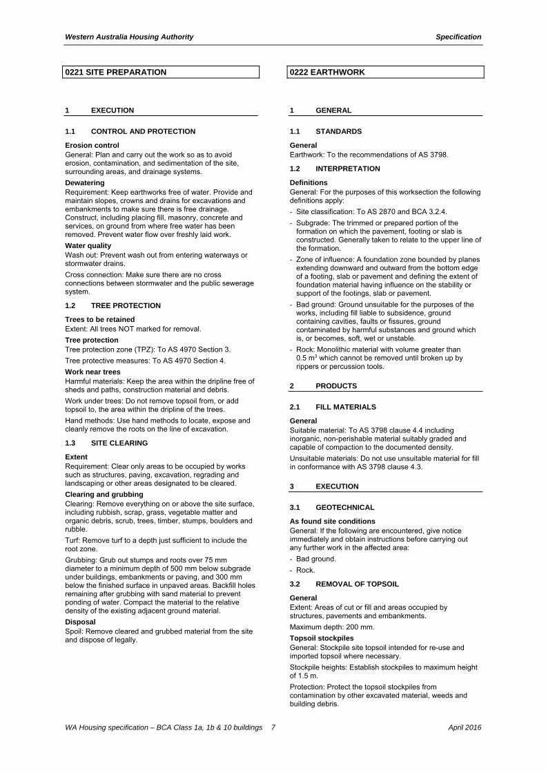
0221 SITE PREPARATION
1 EXECUTION
1.1 CONTROL AND PROTECTION
Erosion control General: Plan and carry out the work so as to avoid erosion, contamination, and sedimentation of the site, surrounding areas, and drainage systems.
Dewatering Requirement: Keep earthworks free of water. Provide and maintain slopes, crowns and drains for excavations and embankments to make sure there is free drainage. Construct, including placing fill, masonry, concrete and services, on ground from where free water has been removed. Prevent water flow over freshly laid work.
Water quality Wash out: Prevent wash out from entering waterways or stormwater drains.
Cross connection: Make sure there are no cross connections between stormwater and the public sewerage system.
1.2 TREE PROTECTION
Trees to be retained Extent: All trees NOT marked for removal.
Tree protection Tree protection zone (TPZ): To AS 4970 Section 3.
Tree protective measures: To AS 4970 Section 4.
Work near trees Harmful materials: Keep the area within the dripline free of sheds and paths, construction material and debris.
Work under trees: Do not remove topsoil from, or add topsoil to, the area within the dripline of the trees.
Hand methods: Use hand methods to locate, expose and cleanly remove the roots on the line of excavation.
1.3 SITE CLEARING
Extent Requirement: Clear only areas to be occupied by works such as structures, paving, excavation, regrading and landscaping or other areas designated to be cleared.
Clearing and grubbing Clearing: Remove everything on or above the site surface, including rubbish, scrap, grass, vegetable matter and organic debris, scrub, trees, timber, stumps, boulders and rubble.
Turf: Remove turf to a depth just sufficient to include the root zone.
Grubbing: Grub out stumps and roots over 75 mm diameter to a minimum depth of 500 mm below subgrade under buildings, embankments or paving, and 300 mm below the finished surface in unpaved areas. Backfill holes remaining after grubbing with sand material to prevent ponding of water. Compact the material to the relative density of the existing adjacent ground material.
Disposal Spoil: Remove cleared and grubbed material from the site and dispose of legally.
0222 EARTHWORK
1 GENERAL
1.1 STANDARDS
General Earthwork: To the recommendations of AS 3798.
1.2 INTERPRETATION
Definitions General: For the purposes of this worksection the following definitions apply:
- Site classification: To AS 2870 and BCA 3.2.4.
- Subgrade: The trimmed or prepared portion of the formation on which the pavement, footing or slab is constructed. Generally taken to relate to the upper line of the formation.
- Zone of influence: A foundation zone bounded by planes extending downward and outward from the bottom edge of a footing, slab or pavement and defining the extent of foundation material having influence on the stability or support of the footings, slab or pavement.
- Bad ground: Ground unsuitable for the purposes of the works, including fill liable to subsidence, ground containing cavities, faults or fissures, ground contaminated by harmful substances and ground which is, or becomes, soft, wet or unstable.
- Rock: Monolithic material with volume greater than 0.5 m3 which cannot be removed until broken up by rippers or percussion tools.
2 PRODUCTS
2.1 FILL MATERIALS
General Suitable material: To AS 3798 clause 4.4 including inorganic, non-perishable material suitably graded and capable of compaction to the documented density.
Unsuitable materials: Do not use unsuitable material for fill in conformance with AS 3798 clause 4.3.
3 EXECUTION
3.1 GEOTECHNICAL
As found site conditions General: If the following are encountered, give notice immediately and obtain instructions before carrying out any further work in the affected area:
- Bad ground.
- Rock.
3.2 REMOVAL OF TOPSOIL
General Extent: Areas of cut or fill and areas occupied by structures, pavements and embankments.
Maximum depth: 200 mm.
Topsoil stockpiles General: Stockpile site topsoil intended for re-use and imported topsoil where necessary.
Stockpile heights: Establish stockpiles to maximum height of 1.5 m.
Protection: Protect the topsoil stockpiles from contamination by other excavated material, weeds and building debris.

Western Australia Housing Authority Specification
WA Housing specification – BCA Class 1a, 1b & 10 buildings 8 April 2016
3.3 EXCAVATION
Extent Clearing: Clear areas to be occupied by the building or other works such as paving, landscaping and excavation, 1500 mm clear of the building or to the allotment boundaries, whichever is less.
Site surface: Excavate over the site to give correct levels and profiles required as the basis for structures, paving and landscaping. Make allowance for compaction or settlement or heaving.
Footings: Excavate for footings to the required sizes and depths. Confirm that the foundation conditions meet the design bearing capacity.
Crawl space: Provide a clear space under timber or steel bearers:
- Minimum clearance: 400 mm.
Rock General: Do not use explosives.
Existing footings Requirement: If excavation is required within the zone of influence of an existing footing, use methods including (temporary) shoring and underpinning that maintain the support of the footing and make sure that the structure and finishes supported by the footing are not damaged.
Existing services Utility services: Contact DIAL BEFORE YOU DIG to identify location of underground utility services pipes and cables.
Bearing surfaces General: Provide even plane bearing surfaces for loadbearing elements including footings. Step to accommodate level changes. Make the steps to the appropriate courses if supporting masonry.
Reinstatement of excavation Requirement: If excavation exceeds the required depth, or deteriorates, reinstate with fill to the correct depth, level and bearing value.
Other buildings/adjoining properties Requirement: Carry out excavation within 3 m of other buildings and boundaries to BCA 3.1.1 and BCA 3.1.2, and the requirements of a structural engineer.
Grading External areas: Grade to give falls away from buildings, minimum 1:100.
Subfloor areas: Grade the ground surface under suspended floors to drain ground or surface water away from buildings without ponding.
3.4 PREPARATION FOR FILLING
Preparation Stripping: Prepare the ground surface before placing fill (including topsoil fill), ground slabs or load bearing elements to AS 3798 clause 6.1.5. Remove materials which will inhibit or prevent satisfactory placement of fill layers, loose material, debris and organic matter.
3.5 PLACING FILL
General Fill: Conform to the BCA and the following requirements:
- Sand fill: Not containing gravel sized particles.
- Achieving a blow count of greater than 7/300 mm to the AS 1289 series.
Compaction: Compact as follows:
- Controlled fill (up to 800 mm deep): In layers not more than 300 mm deep using a vibrating plate or roller.
- Rolled fill: (up to 800 mm deep): In layers not more than 300 mm deep using an excavator or similar machine.
Extent: Extend fill 1 m past the building perimeter to a maximum slope of 1(V):2(H) to the natural ground.
Certification: Provide an engineer's signed compaction certificate before construction commences.
Placement: To BCA 3.2.2.
Layers: Place fill in near-horizontal layers of uniform thickness no greater than 150 mm after compaction, deposited systematically across the fill area.
Placing at structures: Place and compact fill in layers simultaneously on both sides of structures, culverts and pipelines to avoid differential loading.
Moisture content: Adjust the moisture content of fill during compaction within the range of 85 – 115% of the optimum moisture content determined by AS 1289.5.1.1 or AS 1289.5.2.1 as appropriate, in order to achieve the required density.
Compaction Density: Compact the subgrade and each layer of fill to the required depth and density, as a systematic construction operation. Shape surfaces to provide drainage and prevent ponding.
Excavated and stripped ground surface: After excavation and/or stripping, compact these surfaces to minimum depth of 150 mm.
Minimum relative compaction: To AS 3798 Table 5.1.
3.6 STONE PITCHING
General Stones: Clean, hard and durable laterite.
- Size: No dimension less than 150 mm or more than 300 mm.
Mortar mix proportion (cement:lime (hydrated or putty):sand): 1:0.1:3.
Bedding layer: Gravel, 30 mm thick.
Laying: Lay stones as follows:
- Lay stone in close fitting pattern rammed into position, spacing in between stones to be 10 mm maximum.
- Fill spaces between the stones with mortar to form an even, sealed surface.
- Keep exposed rock surface free from mortar.

Western Australia Housing Authority Specification
WA Housing specification – BCA Class 1a, 1b & 10 buildings 9 April 2016
0223 SERVICE TRENCHING
1 PRODUCTS
1.1 FILL MATERIALS
General Backfill material: To FILL MATERIALS in the 0222 Earthwork worksection, free from stones larger than 100 mm maximum dimension and as follows:
- Next to services: Do not place any particles greater in size than 25 mm within 150 mm of services.
- Under paved areas and within 4 m of structures: Coarse sand, controlled low strength material or fine crushed rock.
- In reactive clay: In sites classified M, M-D, H1, H1-D, H2, H2-D, E or E-D to AS 2870, re-use excavated site material at a moisture content within ± 1% of that of the adjoining in situ clay.
2 EXECUTION
2.1 EXISTING SURFACES
Concrete and asphalt pavements Method: Sawcut trench set out lines for the full depths of the bound pavement layers except where the set out line is located along expansion joints.
Segmental paving units Removal: Take up segmental paving units both full and cut by hand, between the trench set out lines, and neatly stack on wooden pallets at locations as directed.
2.2 EXCAVATING
Excavation General: Excavate for underground services in conformance with the following:
- To required lines and levels, with uniform grades.
- Straight between access chambers, inspection points and junctions.
- With stable sides.
Trench widths General: Keep trench widths to the minimum consistent with the laying and bedding of the relevant service and construction of access chambers and pits.
2.3 TRENCH BACKFILL
General Place fill: To PLACING FILL in the 0222 Earthwork worksection.
Timing: Backfill service trenches as soon as possible after laying and bedding the service, if possible on the same working day.
Layers: Compact all material in layers not exceeding 150 mm compacted thickness. Compact each layer to the relative compaction specified before the next layer is commenced.
2.4 SURFACE RESTORATION
General Reinstatement: Reinstate existing surfaces removed or disturbed by trench excavation to match existing and adjacent work.
0241 LANDSCAPE – WALLING AND EDGING C&D
1 PRODUCTS
1.1 TIMBER
Preservative treatment Timber type: Provide only timbers with preservative treatment appropriate to the Hazard class.
Cut surfaces: Provide supplementary preservative treatment to all cut and damaged surfaces.
CCA treated timber: If proposed to be used, provide details.
1.2 SLEEPER WALLS
Sleepers General: To AS 3818.2.
Hardwood: Sound durability class or preservative treated hardwood railway sleepers.
Softwood: Sound preservative treated softwood sleepers.
1.3 CRIB WALLS
General Type: Proprietary system of interlocking precast concrete or preservative treated timber cribs with selected backfill placed and compacted progressively with the crib to form a retaining wall.
Standard for masonry segmental retaining wall units: To AS/NZS 4455.3.
1.4 GEOTEXTILE
General Type: Polymeric fabric formed from a plastic yarn composed of at least 85% by weight of propylene, ethylene, amide or vinyledenechloride and containing stabilisers or inhibitors to make the filaments resistant to deterioration due to ultraviolet light.
Identification and marking: To AS 3705.
Protection General: Provide heavy duty protective covering. Store clear of the ground and out of direct sunlight. During installation do not expose the filter fabric to sunlight for more than 14 days.
1.5 EDGING
Concrete Standard: To AS 1379 – Grade N20.
Concrete kerb Standard: To AS 1379 – Grade N20.
2 EXECUTION
2.1 GENERAL
Set-out General: Set out the positions of walls.
Clearing Extent: Except trees or shrubs to be retained, clear vegetation within 1 m of the landscape walls. Grub out stumps and roots of removed trees or shrubs and trim the grass to ground level, but do not remove the topsoil.
Excavation Extent: Excavate for foundations and footings.

Western Australia Housing Authority Specification
WA Housing specification – BCA Class 1a, 1b & 10 buildings 10 April 2016
2.2 SLEEPER WALLS
Construction Wall: Erect sleeper posts at 2 m centres, buried one third. Brace at half height of wall with sleepers returned into embankment, spiked to posts. Lay sleepers in stretcher bond behind the verticals and securely spike together at joints and at 2 m centres. Back with geotextile and place a 100 mm draining layer of coarse sand or fine gravel between the fabric and backfill.
Backing: Backfill to ground level with compacted fine crushed rock or gravels.
2.3 CRIB WALLS
Construction Construction: Construct walls in conformance with the manufacturer’s written requirements.
2.4 EDGING
Log edges Installation: Excavate to lay logs at least half diameter into the ground. Spike through logs with two 13 mm diameter galvanized mild steel rods per log, penetrating a minimum of 500 mm into the subgrade. Drive the rods flush with the upper surface of the log. Butt the logs together to a close neat fit. Select adjacent logs for similar diameter.
Sawn timber Installation: Set edgings flush with adjoining surfaces. Drive pegs into the ground at 1200 mm centres on the planting side of the edging and on both sides of joints between boards, with peg tops 15 mm below top of edging. Fix the pegs with galvanized nails, two per fixing.
Curving: Space the pegs to hold edging to a uniform curve. Reduce edging thickness to 15 mm if required to enable it to be bent.
Sleeper Installation: Spike through sleepers with two 13 mm diameter galvanized mild steel rods per sleeper, penetrating a minimum of 500 mm into the subgrade. Drive the rods flush with the upper surface of the sleeper. Arris the upper exposed sleeper edges to produce a 15 mm wide face at 45 mm to the edges.
Concrete Edging strip: Place in a shallow trench between timber forms. Wood float finish flush with the adjacent finished grass level. Provide control joints, filled with resilient bituminous material, at 3 m maximum centres.
Concrete kerb Construction: Fixed form, extrusion or slip forms to AS 2876.
Spade work Edges: Define mass planting beds by cutting through soil with garden spade at approximately 70 mm to vertical. Remove sods from garden beds and spread throughout grassed areas.
Finish: Free from kinks in alignment with one curve grading evenly into the next, and free of straight sections.
Brick Setting: On a 1:1:6 (cement:lime:sand) mortar haunch.
Joints: 3 mm struck flush.
Alignment: Even and free from dips, humps and bends.
Cleaning: Wash off mortar progressively.
0242 LANDSCAPE – FENCES AND BARRIERS
1 PRODUCTS
1.1 TIMBER
Posts and rails Hardwood: To AS 2082.
Softwood: To AS 2858.
Pickets and palings Hardwood: To AS 2796.1, Section 8.
- Grade to AS 2796.2: Select.
Softwood: To AS 4785.1, Section 7.
Seasoned cypress pine: To AS 1810, Section 5.
Preservative treatment Timber type: Provide only timbers with preservative treatment appropriate to the Hazard class.
Cut surfaces: Provide supplementary preservative treatment to all cut and damaged surfaces.
CCA treated timber: If proposed to be used, provide details.
1.2 STEEL
Steel tubes Posts, rails, stays and pickets: To AS/NZS 1163.
- Grade: C350L0.
Post and rail finish: Hot-dip galvanized.
1.3 CONCRETE
General Standard: To AS 1379 – N20 or proprietary packaged mix.
1.4 COMPONENTS
Steel panel fencing Steel framing: Zinc-coated or aluminium/zinc alloy coated steel to AS 1397.
Steel sheeting: Prepainted to AS/NZS 2728.
Steel posts Finish: Galvanized.
Timber fencing sizes table
Member Preservative treated soft wood picket (mm)
Preservative treated soft wood paling/lap and cap (mm)
Hardwood or cypress pine paling/lap and cap (mm)
Maximum height
1200 1800 1800
End/corner gate posts
90 x 90 100 x 100 125 x 125 or 100 x 100
Intermediate posts
90 x 90 140 x 45 or 100 x 75
125 x 50 or 100 x 75
Maximum post spacing
2400 2400/2700* 2700*
Rails 70 x 40 75 x 50 or 100x 38
75 x 50 or 100x 38
Picket/paling size
70 x 19 75, 100 or 150* x 15
100 or 150* x 13
Capping - 125 x 35 100 x 50
Footing type Earth Earth Earth
Footing size (diameter x depth)
200 x 600 250 x 600 250 x 600

Western Australia Housing Authority Specification
WA Housing specification – BCA Class 1a, 1b & 10 buildings 11 April 2016
Member Preservative treated soft wood picket (mm)
Preservative treated soft wood paling/lap and cap (mm)
Hardwood or cypress pine paling/lap and cap (mm)
* Three rail fences only
Fencing for swimming pools Design, construction and performance: To AS 1926.1.
Location of fencing for private swimming pools: To AS 1926.2.
2 EXECUTION
2.1 CONSTRUCTION GENERALLY
Set-out General: Set out the fence line and mark the positions of posts, gates and bracing panels.
Property boundaries: Confirm by survey.
Excavation Posts: Excavate post holes so that they have vertical sides and a firm base. Spread surplus material on the principal’s side of the fence.
Erection Line and level: Erect posts vertically. Set heights to follow the contours of natural ground.
Earth footings Base: Place 100 mm of gravel in the footing base under posts.
Compaction: Backfill with earth around posts, compacting firmly by hand or machine in 150 mm deep layers.
Concrete footings In ground: Place mass concrete around posts to protect posts from waterlogged conditions and finish with a weathered top falling 25 mm from the post to ground level.
2.2 FENCING
Steel panel fencing Protection: Make sure bottom rails have drain holes and are at least 50 mm clear of the ground.
Timber fencing General: Mortice posts, taper splice rails and nail twice in mortices. Set pickets and palings clear of the ground.
Picket fence: Nail twice to each rail.
Plain paling fence: Provide 2 rails for fences up to 1800 mm high. Close butt palings and nail twice to each rail.
Lap and cap paling fence: Provide 2 rails for fences up to 1800 mm high, and locate 200 mm from the bottoms of the palings and abutting the tops of palings. Close butt larger palings and nail twice to each rail. Fix smaller palings over joints and nail twice to each rail. Nail capping to the top rail.
Gates Construction: Construct gates as follows:
- Ledges and braces: Match fence rails.
- Pickets or palings: Match fencing.
Hardware: Provide the following:
- Drop bolt and ferrule to each leaf of double gates.
- Latch to one leaf of double gates.
- Provision for locking by padlock.
- Hinges with smooth operation and adjustment for future sagging.
Hand access: Where required provide hand openings to give access from outside to reach locking provision.
0250 LANDSCAPE – GARDENING GROH
1 GENERAL
1.1 STANDARDS
Soils Site and imported topsoil: To AS 4419.
Potting mixes: To AS 3743.
Composts, soil conditioners and mulches: To AS 4454.
2 PRODUCTS
2.1 MATERIAL
Topsoil Requirement: Rock free.
Mix proportion (loam:sand): 1:1.
Source: Provide topsoil which contains organic matter, will support plant life and is free from stones, contaminants and weeds.
Site: If available, provide material recovered from the site.
Turf Supplier: Obtain turf from a specialist grower of cultivated turf.
Quality: Provide turf of even thickness, free from weeds and other foreign matter.
Fertiliser General: Provide proprietary fertilisers, delivered to the site in sealed bags marked to show manufacturer or vendor, weight, fertiliser type, N:P:K ratio, recommended uses and application rates.
Plants Health: Supply plants with foliage size, texture and colour at time of delivery consistent with the size, texture and colour shown in healthy specimens of the nominated species.
Vigour: Supply plants with extension growth consistent with that exhibited in vigorous specimens of the species nominated.
Damage: Supply plants free from damage and from restricted habit due to growth in nursery rows.
Pests and disease: Supply plants with foliage free from attack by pests or disease.
Irrigation Micro-irrigation systems:
- Tubing: Polyethylene micro-irrigation pipe.
Integrated drip line systems: Tubing with integral drippers inserted into the tube during manufacture.
Irrigation controllers: Programmable automatic controllers.
3 EXECUTION
3.1 PREPARATION GROH
Site clearing Requirement: Clear entire site except where trees are documented on drawings to be retained. Clear rear and front yards, including front verges, rake and machine to an even gradient before handover.
Weed eradication Herbicide: Eradicate weeds with a non-residual glyphosate herbicide in any of its registered formulae, at the recommended maximum rate.

Western Australia Housing Authority Specification
WA Housing specification – BCA Class 1a, 1b & 10 buildings 12 April 2016
Earth mounds Placing: Place clean fill in layers approximately 150 mm thick compacted to 85% of the dry density ratio of the surrounding soil as determined by AS 1289.5.4.1. Minimise slumping and further compaction.
Edges: Construct changes in grade over a minimum width of 500 mm to smooth, gradual and rounded profiles with no distinct joint.
Existing trees: Maintain the natural ground level under the canopy.
Planting beds Excavated: Excavate to bring the subsoil to at least 300 mm below finished design levels. Shape the subsoil to fall to subsoil drains where required. Break up the subsoil to a further depth of 100 mm.
Unexcavated: Remove weeds, roots, building rubbish and other debris. Bring the planting bed to 75 mm below finished design levels.
Services and roots: Do not disturb services or tree roots; if necessary cultivate these areas by hand.
Placing topsoil General: Spread the topsoil on the prepared subsoil and grade evenly, making the necessary allowances to permit the following:
- Required finished levels and contours may be achieved after light compaction.
- Grassed areas may be finished flush with adjacent hard surfaces such as kerbs, paths and mowing strips.
Topsoil depths Requirement: Minimum 100 mm thick garden soil over the entire site, excluding areas covered by buildings and paving.
Front and common areas finished soil level: 75 mm below finished height of paths and driveways, ready for planting by others.
3.2 TURFING
General Supply: Deliver the turf within 24 hours of cutting, and lay it within 36 hours of cutting. Prevent the turf from drying out between cutting and laying. If it is not laid within 36 hours of cutting, roll it out on a flat surface with the grass up, and water as necessary to maintain a good condition.
Laying: Lay the turf in the following manner:
- In stretcher pattern with the joints staggered and close butted.
- Parallel with the long sides of level areas, and with contours on slopes.
- To finish flush, after tamping, with adjacent finished surfaces of ground, paving edging, or grass seeded areas.
Tamping: Lightly tamp to an even surface immediately after laying. Do not use a roller.
Fertilising: Mix the fertiliser thoroughly into the topsoil before placing the turf. Apply lawn fertiliser at the completion of the first and last mowings, and at other times as required to maintain healthy grass cover.
Watering: Water immediately after laying until the topsoil is moistened to its full depth. Continue watering to maintain moisture to this depth.
Levels: If levels have deviated from the design levels after placing and watering, lift turf and regrade topsoil to achieve design levels.
3.3 PLANTING
General Individual plantings in grassed areas: Excavate a hole twice the diameter of the root ball and at least 100 mm deeper than the root ball. Break up the base of the hole to
a further depth of 100 mm, and loosen compacted sides of the hole to prevent confinement of root growth.
Watering: Thoroughly water the plants before planting, immediately after planting, and as required to maintain growth rates free of stress.
Placing: Remove the plant from the container with minimum disturbance to the root ball, make sure that the root ball is moist and place it in its final position, in the centre of the hole and plumb, and with the top soil level of the plant root ball level with the finished surface of the surrounding soil.
Fertilising: In planting beds and individual plantings, place fertiliser pellets around the plants at the time of planting.
Backfilling: Backfill with topsoil mixture. Tamp lightly and water to eliminate air pockets.
3.4 WATERING GROH
General Requirement: Comply with local restrictions.
Reticulation Extent: To all landscaped areas.
Water supply: From a separate cut in within 2 m of the master mains water meter, with a 25 mm tested gate valve fitted with an approved backflow prevention device.
Reticulation sleeves: Provide as follows:
- 100 mm PVC-U sleeve 300 mm below driveways where reticulation is documented on drawings. Where reticulation is not documented on drawings, provide sleeve at the junction of driveway and carport floor.
- Provide a 90° elbow to each end, 300 mm out from the ground, visible for the landscaper.
- Fit sleeves in one straight length under the driveway to allow draw wires to be easily drawn through the sleeve.
Solenoid conduit: Supply and install 15 mm diameter PVC conduit with draw wire from the garden reticulation cabinet, adjacent paths, hardstands and driveways to the nearest garden bed.
Garden reticulation cabinet: Provide where documented on drawings. Install a 10 amp 250 volt socket outlet in the cabinet.
- Supply conduit and draw wire to the reticulation cabinet.
- Position socket outlet at the bottom right hand corner of cabinet and connect to common services power circuit.
Socket outlet label: SUPPLIED BY COMMON SERVICES POWER CIRCUIT.
3.5 MULCHING
Placing mulch General: Place mulch to the required depth, clear of plant stems, and rake to an even surface flush with the surrounding finished levels. Spread and roll mulch so that after settling, or after rolling, it is smooth and evenly graded between design surface levels sloped towards the base of plant stems in plantation beds, and not closer to the stem than 50 mm in the case of gravel mulches.
Depths: Spread organic mulch to a depth of 75 mm, and gravel mulch to a depth of 50 mm.
3.6 STAKES AND TIES
Stakes Material: Hardwood, straight, free from knots or twists, pointed at one end.
Installation: Drive stakes into the ground at least one third of their length, avoiding damage to the root system.
Ties General: Provide 50 mm hessian webbing ties fixed securely to the stakes, one tie at half the height of the main stem, others as necessary to stabilise the plant. Attach ties loosely.

Western Australia Housing Authority Specification
WA Housing specification – BCA Class 1a, 1b & 10 buildings 13 April 2016
3.7 COMPLETION
Cleaning Stakes and ties: Remove those no longer required at the end of the planting establishment period.
Temporary fences: Remove temporary protective fences at the end of the planting establishment period.
0271 PAVEMENT BASE AND SUBBASE GROH
1 PRODUCTS
1.1 BASE AND SUBBASE MATERIAL GROH
Granular material Requirement: Provide unbound granular materials, including blends of two or more different materials which when compacted develop structural stability and are uniform in grading and physical characteristics.
Crushed rock and recycled material class Requirement: Provide crushed rock and recycled material as documented, from the following classes:
- Class 2: Pavement base material (with no minimum plasticity index) for unbound pavements which may not require a very high standard of surface preparation.
- Class 3: Subbase material for unbound flexible pavements.
2 EXECUTION
2.1 SUBGRADE PREPARATION
General Requirement: Prepare the subgrade in conformance with the 0222 Earthwork worksection.
2.2 PLACING BASE AND SUBBASE
General Weak surfaces: Do not place material on a surface that is weakened by moisture and is unable to support, without damage, the construction plant required to perform the works.
Spreading: Spread material in uniform layers without segregation.
Moisture content: Maintain wet mixed materials at the required moisture content before and during spreading. Add water to dry mixed materials through fine sprays to the entire surface of the layer after spreading, to bring the material to the required moisture content.
Compacted layer thickness: 200 mm maximum and 100 mm minimum. Provide layers of equal thickness in multilayer courses.
2.3 TOLERANCES
Surface level General: Provide a finished surface level which is free draining and evenly graded between level points.
2.4 BASE AND SUBBASE COMPACTION
General Construction operation: Compact each layer of fill to the required depth and density, as a systematic construction operation.
Minimum relative compaction table
Item description Minimum dry density ratio (modified compaction) to AS 1289.5.2.1
Subbase 95%
Base 98%
Compaction requirements General: Apply uniform compactive effort, over the whole area to be compacted, until the required density is achieved or until failure is acknowledged.

Western Australia Housing Authority Specification
WA Housing specification – BCA Class 1a, 1b & 10 buildings 14 April 2016
Equipment: Use rollers appropriate to the materials and compaction requirements documented.
0274 CONCRETE PAVEMENT GROH
1 GENERAL
1.1 STANDARDS
General Specification and supply: To AS 1379.
Materials and construction: To AS 3600.
Guide to residential pavements: To AS 3727.
Vapour barrier Requirement: Conform to the 0171 General requirements worksection.
Grading General: Grade paving to even falls to drain away from buildings to drainage outlets without ponding.
Minimum fall for drainage: 1:100.
2 EXECUTION
2.1 GENERAL
Preparation General: Trim the ground to suit the required thickness of concrete and compact to a firm, even surface.
Prepared subgrade: Blind with sufficient sand to create a smooth surface free from hard projections. Wet the sand just before laying the underlay.
Paving General: Place and compact concrete paving over a vapour barrier placed over the prepared ground surface.
Grading General: Grade paving to even falls to drain away from buildings to drainage outlets without ponding.
Minimum fall for drainage: 1:100.
Thickness Minimum:
- Foot and bicycle traffic: 75 mm.
- Light domestic traffic occasionally up to 3 tonne gross: 100 mm.
Curing General: Protect fresh concrete from premature drying and from excessively hot or cold temperatures. Maintain the concrete at a reasonably constant temperature with minimum moisture loss for the curing period of 7 days.
2.2 JOINTS
Contraction joints General: Form tooled joints at maximum 2000 mm spacing.
Expansion joints General: Cast-in 10 mm thick bitumen impregnated fibreboard at maximum 6 m spacing.
Abutment with building General: Where concrete paving more than 1500 mm wide abuts the wall of a building, cast-in 10 mm thick bitumen impregnated fibreboard between the paving and the wall. Otherwise, turn up the vapour barrier.
2.3 FINISHING METHODS
Finishes Broom finishing: Wood float and broom to an even textured transverse scored surface with steel tooled margins. On gradients steeper than 10%, roughen the surface by scoring using a stiff brush or rake.

Western Australia Housing Authority Specification
WA Housing specification – BCA Class 1a, 1b & 10 buildings 15 April 2016
Exposed aggregate finish: Steel trowel to a smooth surface. After final set use clean water and brushes to remove the surface film of mortar until the aggregate is uniformly exposed without under cutting of the matrix.
Sponge finish: After floating, produce an even textured sand finish by wiping the surface using a damp sponge.
Pattern paving: After machine floating, apply a proprietary treatment producing an integral coloured and patterned surface.
2.4 DRIVEWAY, GARAGE OR CARPORT FLOORS
General Compact base: To AS 1289.5.2.1.
Finish: Granolithic finish.
0276 PAVING – SAND BED
1 GENERAL
1.1 STANDARDS
General Concrete and clay pavers: To AS/NZS 4455.2.
1.2 PAVER THICKNESS
General Requirement: Minimum thickness:
- Foot and bicycle traffic: 40 mm.
- Light domestic traffic occasionally up to 3 tonne gross: 50 mm.
2 PRODUCTS
2.1 MATERIALS
Sand Bedding and joint filling: Well-graded and free of deleterious materials such as soluble salts which may cause efflorescence.
Cement Standard: To AS 3972, type GP.
Mortar Mix proportions (cement:sand): 1:3.
2.2 COMPONENTS
Masonry units and pavers General: Provide pavers of clay, natural stone or concrete masonry, purpose-made for use as paving, or units made for bonded masonry construction but suitable for paving.
3 EXECUTION
3.1 GENERAL
Preparation General: Trim the subgrade to the required profile and to suit the thickness of pavers and sand bed. Compact to a firm, even surface.
Base course General: Conform to the 0271 Pavement base and subbase worksection.
Edge restraint Perimeter: If not provided by other structures, provide edge restraints to bedding and units.
Type: Bed units in mortar at least 40 mm thick.
Drainage: Position the edge restraint and pavers so that the top of the pavers is slightly above the front edge of the edge restraint.
Bedding course Preparation: Remove all loose material from the prepared base.
Geotextile: Place fabric between the base course and the bedding sand.
Bedding sand: Screed uncompacted sand over prepared base uniformly to achieve a 30 mm thick layer. Maintain sand at a uniform loose density and moisture content.
Grading General: Grade paving to even falls to drain away from buildings to drainage outlets without ponding.
Minimum fall for drainage: 1:100.
Western Australia Housing Authority Specification
WA Housing specification – BCA Class 1a, 1b & 10 buildings 16 April 2016
Cutting Cutting units: Cut paving units to maintain sharp edges and accurate joints and margins.
Laying General: Lay paving units on the screeded sand bedding to the nominated pattern shown on the drawings.
Joints: 2 to 5 mm gap.
Cut courses: 50 mm minimum plan dimension. On footpaths and other linear elements, use at least two cut courses and maintain symmetry.
Compaction: Compact the sand bedding after laying paving units using a vibrating plate compactor and appropriate hand methods, and continue until lipping between adjoining units is eliminated.
Joint filling: Spread dry sand over the paving units and fill the joints by brooming. Carry out one or more passes with the vibrating plate compactor and refill the joints with sand. Repeat the process until the joints are completely filled.
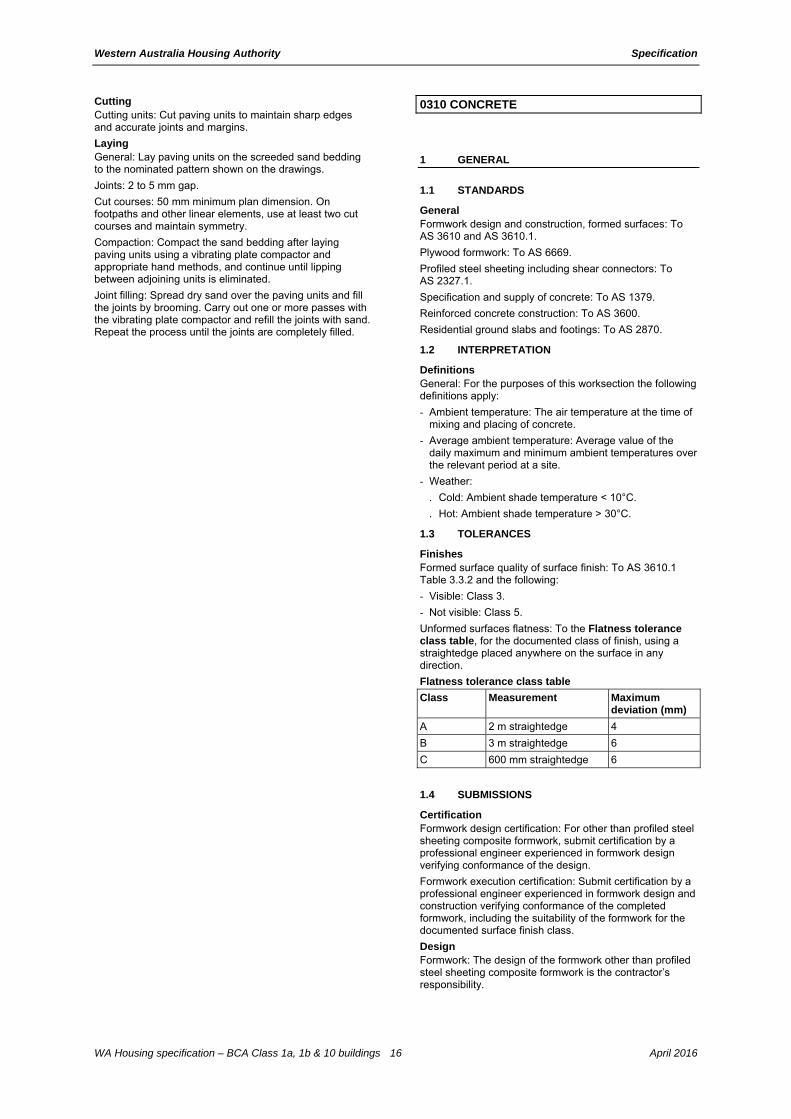
0310 CONCRETE
1 GENERAL
1.1 STANDARDS
General Formwork design and construction, formed surfaces: To AS 3610 and AS 3610.1.
Plywood formwork: To AS 6669.
Profiled steel sheeting including shear connectors: To AS 2327.1.
Specification and supply of concrete: To AS 1379.
Reinforced concrete construction: To AS 3600.
Residential ground slabs and footings: To AS 2870.
1.2 INTERPRETATION
Definitions General: For the purposes of this worksection the following definitions apply:
- Ambient temperature: The air temperature at the time of mixing and placing of concrete.
- Average ambient temperature: Average value of the daily maximum and minimum ambient temperatures over the relevant period at a site.
- Weather:
. Cold: Ambient shade temperature < 10°C.
. Hot: Ambient shade temperature > 30°C.
1.3 TOLERANCES
Finishes Formed surface quality of surface finish: To AS 3610.1 Table 3.3.2 and the following:
- Visible: Class 3.
- Not visible: Class 5.
Unformed surfaces flatness: To the Flatness tolerance class table, for the documented class of finish, using a straightedge placed anywhere on the surface in any direction.
Flatness tolerance class table
Class Measurement Maximum deviation (mm)
A 2 m straightedge 4
B 3 m straightedge 6
C 600 mm straightedge 6
1.4 SUBMISSIONS
Certification Formwork design certification: For other than profiled steel sheeting composite formwork, submit certification by a professional engineer experienced in formwork design verifying conformance of the design.
Formwork execution certification: Submit certification by a professional engineer experienced in formwork design and construction verifying conformance of the completed formwork, including the suitability of the formwork for the documented surface finish class.
Design Formwork: The design of the formwork other than profiled steel sheeting composite formwork is the contractor’s responsibility.

Western Australia Housing Authority Specification
WA Housing specification – BCA Class 1a, 1b & 10 buildings 17 April 2016
2 PRODUCTS
2.1 MATERIALS
Cement Standard: To AS 3972.
Age: Less than 6 months old.
Storage: Store cement bags under cover and above ground.
Pre-mixed concrete supply Standard: To AS 1379 by the batch production process.
Maximum slump: 100 mm.
Polymeric film underlay Vapour barriers and damp-proofing membranes: To AS 2870 clause 5.3.3.
Curing compounds Curing compounds: To AS 3799.
2.2 FORMWORK
General Lost formwork: Free of timber or chlorides and not to impair the structural performance of the concrete members.
Profiled steel sheeting composite formwork Material: Hot-dipped zinc-coated sheet steel to AS 1397.
Minimum steel grade: G550.
Accessories: Adopt material and corrosion protection to match the profiled steel sheeting.
Plywood formwork Material: To AS 6669.
Grade: Use appropriate grade for the documented design dimensions, loading and surface quality.
Joints: Seal the joints consistent with the documented surface finish class.
Tolerances: To AS 3610.1 Section 3.
3 EXECUTION
3.1 POLYMERIC FILM UNDERLAY
Location General: Under slabs on ground including integral ground beams and footings, provide a vapour barrier or, in areas prone to rising damp or salt attack, a damp-proofing membrane.
3.2 FORMWORK
Preparation Cleaning: Before placing concrete, remove free water, dust, debris and stains from the formwork and the formed space.
Corners Work above ground: Chamfer at re-entrant angles, and fillet at corners.
- Face of bevel: 25 mm.
Void formers Protection: Keep void formers dry until time of use. Place them on a firm level surface and place reinforcement and concrete with minimum delay.
3.3 REINFORCEMENT
Supports Proprietary concrete, metal or plastic supports: To AS/NZS 2425 and as follows:
- Able to withstand construction and traffic loads.
- With a protective coating if they are ferrous metal, located within the concrete cover zone, or are used with galvanized or zinc-coated reinforcement.
Spacing:
- Bars: ≤ 60 diameters.
- Mesh: ≤ 800 mm.
Supports over membranes: Prevent damage to waterproofing membranes or vapour barriers. If appropriate, place a metal or plastic plate under each support.
Projecting reinforcement Protection: If starter or other bars extend beyond reinforcement mats or cages, through formwork or from cast concrete, provide a plastic protective cap to each bar until it is cast into later work.
Tying General: Secure the reinforcement against displacement at intersections with either wire ties, or clips. Bend the ends of wire ties away from nearby faces of formwork or unformed faces to prevent the ties do not project into the concrete cover.
Minimum requirements Splices: Splice as follows:
- Mesh sheets: 225 mm.
- Trench mesh: 500 mm.
- Bars: Greater of either 500 mm or 25 x bar diameter.
- Strip footing intersections and corners: Full width of intersecting reinforcement.
Minimum cover to reinforcement table
Concrete element
Location Minimum concrete strength (MPa)
Minimum cover to reinforcement (mm)
Unreinforced concrete
Generally 20
Reinforced concrete
Unless noted otherwise below
25 20
Exterior: Temperate, near-coastal (1 km to 50 km) and on ground and protected by membrane (bottom cover)
25 30
On ground and unprotected by membrane (bottom cover)
25 40
Footings 25 50
Exterior: Tropical, near-coastal (1 km to 50 km) and in contact with fresh water
32 40
Exterior: Coastal (100 m to 1 km) and permanently submerged in salt water
40 45
Exterior: In tidal or splash zones
50 50
3.4 CONCRETE
Placing Method: Avoid segregation and loss of concrete, and minimise plastic settlement. Maintain a nominally vertical and plastic concrete edge during placement.

Western Australia Housing Authority Specification
WA Housing specification – BCA Class 1a, 1b & 10 buildings 18 April 2016
Horizontal elements: Place concrete in layers not more than 300 mm thick. Compact the following layer into previous layer before previous layer has taken initial set.
Compaction Methods: Use immersion and screed vibrators accompanied by hand methods as appropriate to remove entrapped air and to fully compact the mix.
Vibrators: Do not allow vibrators to contact set concrete, reinforcement or items including pipes and conduits embedded in concrete. Do not use vibrators to move concrete along the formwork. Avoid causing segregation by over-vibration.
Rain Protection: During placement and before setting, protect the surface from damage.
Placing in cold weather Temperature limits: Maintain the following temperature limits:
- Freshly mixed concrete: ≥ 5°C.
- Formwork and reinforcement before and during placing: ≥ 5°C.
- Water: Maximum 60°C when placed in mixer.
Temperature control: Heat the concrete materials, other than cement, to the minimum temperature necessary so that the temperature of the placed concrete is within the documented limits.
Placing in hot weather Temperature limits: Maintain the following temperature limits:
- Freshly mixed concrete at ≤ 35°C.
- Formwork and reinforcement before and during placing: ≤ 35°C.
Temperature control: Select one or more of the following methods of maintaining the temperature of the placed concrete at 35°C or less:
- Cover the horizontal transport containers.
- Spray the coarse aggregate using cold water prior to mixing.
- Use chilled mixing water.
Evaporation control barriers: Erect barriers to protect freshly placed concrete from drying winds.
3.5 CURING
General Requirements: Taking into account the average ambient temperature at site over the relevant period affecting the curing and adopt procedures to make sure the following:
- Curing: Cure continuously from completion of finishing until the total cumulative number of days or fractions of days, during which the air temperature in contact with the concrete is above 10°C, conforms to the following:
. Fully enclosed internal surfaces: 3 days.
. Other concrete surfaces: 7 days.
- End of curing period: Prevent rapid drying out at the end of the curing period.
- Protection: Maintain at a reasonably constant temperature with minimum moisture loss, during the curing period.
Curing compounds Application: Provide a uniform continuous flexible coating without visible breaks or pinholes, which remains unbroken at least for the required curing period after application.
Substrates: Do not use wax-based or chlorinated rubber-based curing compounds on surfaces forming substrates to applied finishes, concrete toppings and cement-based render.
Cold weather curing Temperature: Maintain concrete surface temperature above 5°C for the duration of the curing period.
Hot weather curing Protection: Provide protection as follows:
- Immediately after finishing, either cover exposed surfaces using an impervious membrane or hessian kept wet until curing begins, or apply a curing compound.
Water curing Method: Select a method of ponding or continuously sprinkling water to prevent damage to the concrete surface during the required curing period.
3.6 JOINTS
Construction joints Location: Do not relocate or eliminate construction joints, or form undocumented construction joints. If emergency construction joints are made necessary by unforeseen interruptions to the concrete pour, submit a report on the action taken.
Preparation: Roughen and clean the hardened concrete joint surface. Remove loose or soft material, free water, foreign matter and laitance. Dampen the surface just before placing the fresh concrete and coat with a neat cement slurry.
Slip joints Requirement: If concrete slabs are supported on masonry, provide proprietary slip joints.
3.7 FORMED SURFACES
General Damage: Do not damage concrete works through premature removal of formwork.
Curing General: If formwork is stripped before the minimum curing period for the concrete has elapsed, continue curing the exposed faces as soon as the stripping is completed.
Surface repairs Method: If surface repairs are required, submit proposals.
3.8 UNFORMED SURFACES
Surface finishes General: As documented.
Surface repairs Method: If surface repairs are required, submit proposals.
3.9 COMPLETION
Formwork removal Extent: Remove formwork, other than profiled steel sheeting composite formwork and lost formwork, including formwork in concealed locations.
Timing: Do not disturb formwork until concrete is hardened enough to withstand formwork movements and removal without damage.
Stripping times: Leave formwork for suspended structures in place after pouring concrete for the following periods:
- Vertical surfaces: 2 days.
- Bottom surfaces: 7 days with shoring and backprops left in position for 21 days.
Protection General: Protect the concrete from damage due to construction loads, physical and thermal shocks and excessive vibrations, particularly during the curing period.
Surface protection: Protect finished concrete surfaces and applied finishes from damage.
Western Australia Housing Authority Specification
WA Housing specification – BCA Class 1a, 1b & 10 buildings 19 April 2016
0331 BRICK AND BLOCK CONSTRUCTION GROH
1 GENERAL
1.1 STANDARD
General Materials and construction: To AS 4773.1 and AS 4773.2.
Design and construction: To AS 3700.
2 PRODUCTS
2.1 DURABILITY
General Exposure locations: To AS 4773.1 clause 4.4.
2.2 MATERIALS
Bricks and blocks Standard: To AS/NZS 4455.1 and AS/NZS 4455.3.
Minimum age of clay bricks: 7 days.
Salt attack resistance grade: To AS 4773.2 Table 2.1.
Mortar materials Sand: Fine aggregate with a low clay content and free from efflorescing salts, selected for colour and grading.
Mortar mixes: To AS 3700. Include any additives such as colouring, as documented.
Proportions: To AS 4773.1 Table 3.1
2.3 BUILT-IN COMPONENTS
General Durability class of built-in components: To AS 4773.1 Table 4.1.
Steel lintels Angles and flats: Sizes to AS 4773.1 Table 12.2.
Cold-formed lintels: Designed to AS/NZS 4600.
Corrosion protection: To AS/NZS 2699.3.
Galvanizing: Do not cut after galvanizing.
Wall ties Standard: To AS/NZS 2699.1.
Type: A.
Corrosion protection: To AS/NZS 2699.1.
Connectors and accessories Standard: To AS/NZS 2699.2.
Corrosion protection: To AS/NZS 2699.2.
Flashings and damp-proof courses Standard: To AS/NZS 2904.
Weepholes Type: Moulded plastic weephole formers with a vermin proof gate.
3 EXECUTION
3.1 GENERAL
Mortar mixing General: Measure volumes accurately to the documented proportions. Machine mix for at least six minutes.
Protection from contamination General: Protect masonry materials and components from ground moisture and contamination.
Bond Type: Stretcher bond.
Building in Embedded items: Build in wall ties and accessories as the construction proceeds. If it is not practicable to obtain the required embedment wholly in the mortar joint in hollow masonry units, fill appropriate cores with grout or mortar.
Clearance for timber frame shrinkage General: In timber frame brick veneer construction, leave clearances between window frames and brick sill and between roof frames and the brick veneer as follows:
- Additional clearance: Accommodate additional shrinkage of unseasoned floor timbers.
- Single storey frames and ground floor windows (not for slab on ground): 10 mm.
- Two storey frames and upper floor windows: 20 mm.
Joining to existing General: Provide a control joint where joining to existing structures. Do not tooth new masonry into existing work unless approved by a professional engineer.
Mortar joints Solid and cored units: Lay on a full bed of mortar. Fill perpends solid. Cut mortar flush.
Face-shell bedded hollow units: Fill perpends solid. Cut mortar flush.
Finish: Conform to the following:
- Externally: Tool to give a dense water-shedding finish.
- Internally: If wall is to be plastered, do not rake more than 10 mm to give a key.
- Thickness: 10 mm.
Cutting: Set out masonry with joints of uniform width and the minimum of cutting of masonry units.
Rate of construction General: Regulate the rate of construction to eliminate joint deformation, slumping or instability.
Rods Set-out: Construct masonry to the following rods:
- 75 mm high units: 7 courses to 600 mm.
- 90 mm high units: 6 courses to 600 mm.
- 190 mm high units: 3 courses to 600 mm.
Piers Isolated piers in carport, veranda or similar: Construct as follows:
- Size: Not less than 290 x 290 mm and not more than 2.7 m high.
- Spacing: Not more than 3.0 m centres.
- Reinforced to BCA 3.3.2 or a professional engineer’s requirements.
Meter box Location: As documented on drawings.
Storerooms Requirement: Apply 3 coats of waterproofing clear or transparent sealer to the external walls of storerooms.
3.2 FACEWORK
Cleaning General: Clean progressively as the work proceeds to remove mortar smears, stains and discolouration. Do not erode joints if using pressure spraying.
Acid solution: Do not use.
Colour mixing Distribution: In facework, distribute the colour range of units evenly to prevent colour concentrations and banding.
Sills and thresholds General: Solidly bed sills and thresholds and lay them with the top surfaces drain away from the building.
Minimum size of unit: Three quarters full width.

Western Australia Housing Authority Specification
WA Housing specification – BCA Class 1a, 1b & 10 buildings 20 April 2016
3.3 SUBFLOOR WORK
Bearer piers Provide engaged or free standing unreinforced masonry piers to support bearers at 1800 mm maximum centres and to the Bearer pier table.
Bearer pier table
Type Minimum size (mm)
Engaged 230 x 110 bonded or tied to walls
Freestanding up to 1500 mm high 230 x 230
Freestanding 1500 to 2700 mm high 350 x 350
Access openings General: In internal walls, leave door-width openings beneath doorways to give access to underfloor areas.
Air vent location General: Provide air vents to give adequate cross ventilation to the space under suspended ground floors.
Cavity walls: Provide matching vents in the internal leaves located as near as practicable to the air vents in the external leaves.
Location: Below damp-proof course to internal and external walls.
Minimum provision: 6000 mm2 net ventilation area per linear metre of wall.
Underpinning Requirement: Install underpinning while maintaining the building undamaged.
Grouting: Pack dry mix M4 mortar between underpinning and existing structure within 24 and 48 hours of completion of each panel of underpinning.
3.4 CAVITY WORK
Cavity clearance General: Keep cavities clear at all times.
Cavity fill General: Fill the cavity with mortar to 1 course above adjacent finished (ground) level. Fall the top surface towards the outer leaf.
Cavity width General: Construct minimum cavity widths in conformance with the following:
- Masonry walls: 50 mm.
- Masonry veneer walls: 40 mm between the masonry leaf and the loadbearing frame and 25 mm minimum between the masonry leaf and sheet bracing.
Openings Do not close the cavity at the jambs of external openings.
Wall ties connectors and accessories Protection: Install to prevent water passing across the cavity.
3.5 DAMP-PROOF COURSES
Location General: Locate damp-proof courses as follows:
- Timber floors: In the first course below the level of the underside of ground floor timbers in internal walls and inner leaves of cavity walls.
- Cavity walls built off slabs on ground: In the bottom course of the outer leaf, continuous horizontally across the cavity and up the inner face bedded in mortar, turned 30 mm into the inner leaf 1 course above.
- Masonry veneer construction: In the bottom course of the outer leaf, continuous horizontally across the cavity. Fastened to the inner frame 75 mm above floor level.
- Walls adjoining infill floor slabs on membranes: In the course above the underside of the slab in internal walls and inner leaves of cavity walls. Project 40 mm and dress down over the membrane turned up against the wall.
Height: Not less than:
- 150 mm above the adjacent finished ground level.
- 75 mm above the finished paved or concrete area.
- 50 mm above the finished paved or concreted area and protected from the direct effect of the weather.
Installation General: Lay in long lengths. Lap the full width of angles and intersections and 150 mm at joints. Step as necessary, but not more than 2 courses per step for brickwork and 1 course per step for blockwork. Sandwich damp-proof courses between mortar.
Junctions: Preserve continuity of damp-proofing at junctions of damp-proof courses and waterproof membranes.
3.6 FLASHINGS
Location General: Locate flashings as follows:
- Floors: Full width of outer leaf immediately above slab, continuous across cavity and up the inner face bedded in mortar, turned 30 mm into the inner leaf 2 courses above for brick and 1 course for block. If the slab supports the outer skin and is not rebated, bed the flashing in a suitable sealant.
- Under sills: 30 mm into the outer leaf bed joint 1 course below the sill, extending up across the cavity and under the sill in the inner leaf or the frame for masonry veneer. Extend at least 150 mm beyond the reveals on each side of the opening.
- Over lintels to openings: Full width of outer leaf immediately above the lintel, continuous across cavity, turned 30 mm into the inner leaf 2 courses above for brick and 1 course for block or turned up against the frame and fastened to it. Extend at least 150 mm beyond the ends of the lintels.
- At abutments with structural frames or supports: Vertical flash in the cavity from 150 mm wide material, wedged and grouted into a groove in the frame opposite the cavity.
- At jambs: Vertically flash jamb extending 75 mm into the cavity, interleaved with the sill and head flashing at each end. Fix to jambs.
- At roof abutments with cavity walls: Cavity flash immediately above the roof and over-flash the roof apron flashing.
- Cavity masonry walls: Provide where interrupted by structural element (e.g. roof, wall), opening or similar.
Installation General: Sandwich flashings between mortar except where on lintels.
Pointing: Point up joints around flashings to fill voids.
Weepholes Standard: To AS 3700.
Location: Provide weepholes to external leaves of:
- Cavity walls in the course immediately above flashings, and cavity fill, and at the bottoms of unfilled cavities.
- Above suspended floors interrupting cavities.
Form: Open perpends.
Maximum spacing: 1200 mm.
Weephole guards: Provide access barrier.
Installation: To the manufacturer's recommendations.

Western Australia Housing Authority Specification
WA Housing specification – BCA Class 1a, 1b & 10 buildings 21 April 2016
3.7 WALL TIES
Location Spacing: To AS 4773.2 clause 9.7 and clause 10.6.
Installation Embedment: At least 50 mm into mortar ensuring that mortar cover is 15 mm minimum to the outside face of the mortar.
3.8 CONTROL JOINTS
General Location and spacing: Provide contraction joints, expansion joints and articulation joints to AS 4773.2 Section 7.
Control joint filling Installation: Clean the joints thoroughly and insert an easily compressible backing material before sealing.
Sealant depth: Fill the joints with a gun-applied flexible sealant for a depth of at least two-thirds the joint width.
Sealant type: External: UV stable.
Flexible masonry ties Requirement: Provide stabilising ties at control joints and abutting structural elements, including columns, beams and slab soffits.
3.9 REINFORCED AND GROUTED BLOCKWORK
Cleaning core holes General: Provide purpose-made cleanout blocks or machine cut a cleaning hole at the base of each grouted core.
Location: Locate on the side of the wall which is to be rendered or otherwise concealed.
Cleaning: Rod cores to dislodge mortar fins protruding from the blocks and mortar droppings from reinforcement. Remove through the clean-out blocks.
Grouting Commencement: Do not commence until grout spaces have been cleaned out and the mortar joints have attained sufficient strength to resist blow-outs.
Height of lift: Limit the height of individual lifts in any pour to make sure that the grout can be thoroughly compacted to fill all voids.
Compaction: Compact by vibration or by rodding.
Topping up: On the completion of the last lift, top up the grout after 10 min to 30 min, and vibrate or rod to mix with the previous pour.
3.10 LINTELS
Installation General: Do not cut on site. Keep lintels 10 mm clear of heads of frames.
Steel lintels: Pack mortar between any vertical component and supported masonry units. For angles install with the long leg vertical.
Propping: Provide temporary props to lintels to prevent deflection or rotation.
Concrete beam lintels Requirement: To AS 3600 or a professional engineer's requirements.
3.11 BUILT-IN COMPONENTS
Wall ties fixing straps and tie-down systems Installation: To AS 3700 or the AS 4773 series.
Corrosion protection: To AS 3700 clause 5.7 for coastal and industrial areas.
Tie-down straps Type and size: 32 x 0.8 mm or 25 x 1.0 mm galvanized straps.
Spacing: Not more than 1.2 m centres, corresponding with truss/rafter positions to AS 1684.2 and AS/NZS 2699.2 or to the engineer’s requirements.
3.12 BAGGING
Preparation General: Cut joints flush before bagging.
Dry bagging Application: Apply laying mortar to the surface using a hessian bag or similar. Flush up irregularities, but leave a minimum amount of mortar on the surface.

Western Australia Housing Authority Specification
WA Housing specification – BCA Class 1a, 1b & 10 buildings 22 April 2016
0342 LIGHT STEEL FRAMING C&D
1 GENERAL
1.1 STANDARDS
General Design, materials and protection: To AS/NZS 4600.
Residential and low-rise steel framing: To NASH-1 (National Association of Steel Housing) Standard.
Beams and lintels: To BCA 3.4.4, AS 4100 and AS/NZS 4600.
Corrosion protection: To BCA 3.4.4.4 based on steel member exposure (coastal and industrial environments).
- Lintels and masonry accessories: Provide protection to AS/NZS 2699.1, AS/NZS 2699.3 and AS 3700 clause 5.7 as appropriate for the environment classification.
1.2 TOLERANCES
General Manufacturing, assembly and installation tolerances: To NASH-1 Appendix D and NASH-2 Appendix A.
1.3 SUBMISSIONS
Design General: Where the structural drawings define performance criteria, submit independent design, documentation and certification from a professional engineer, including for the erected work.
Reactions: Provide location and magnitude of reactions to be accommodated by the support structure.
Shop drawings General: Submit shop drawings, to a scale that best describes the detail, or product design guide certified by a professional engineer stating that the design has been carried out to AS/NZS 4600 or NASH-1 and NASH-2 requirements for the configurations and loadings. Include the following:
- Prefabricated roof trusses:
. Plan: Truss layout.
. Elevations: Arrangement of members, allowing for the accommodation of in-roof services and the size and section type of each member.
. Holding down and bracing: Details demonstrating capability to resist lateral and uplift forces.
. Method of assembly and connection details.
- Prefabricated wall frames:
. Plan: Wall layout.
. Elevation: Arrangement of members, and size and section type of each member.
. Method of assembly, connection, holding down and bracing.
2 PRODUCTS
2.1 GENERAL C&D
Storage and handling Requirement: Transport all components to site and store if required in a manner so as not to damage or distort the components.
2.2 COMPONENTS
Cold-formed steel framing Cold-form sections from metallic-coated steel: To AS 1397.
Corrosion protection: To BCA 3.4.2.2.
Framing members Cold-formed steel framing: For a proprietary system, comply with NASH-1 and NASH-2.
3 EXECUTION
3.1 GENERAL
Fabrication Length: Cut members accurately to length so that they fit firmly against abutting members.
Service holes: Form holes by drilling or punching.
Bushes: Provide plastic bushes or grommets to site cut holes.
Swarf: Immediately remove swarf and other debris from cold-formed steel framing.
Fastening Type: Select from the following:
- Bolting.
- Self-drilling, self-tapping screws.
- Blind rivets.
- Proprietary clinching system.
- Structural adhesives.
- Welding. On-site welded connections are not permitted.
Welding Burning: Avoid procedures that result in greater than localised burning of the sheets or framing members.
Prefabricated frames General: Protect frames from damage or distortion during erection. Provide temporary protection for members until permanent covering is in place.
Metal separation General: Install lagging to separate non-ferrous service pipes and accessories from the framing.
Unseasoned or CCA treated timber General: Do not fix in contact with framing without fully painting the timber and/or the steel.
Earthing Permanent earthing: Required.
Temporary earthing: Provide temporary earthing during erection until the permanent earthing is installed.
Protection General: Restore coatings which have been damaged by welding or other causes. Thoroughly clean affected areas back to base metal and coat with a zinc rich organic primer.
Grommets: Provide grommets to isolate piping and wiring from cold-formed steel framing.
3.2 FLOOR FRAMING
General Protection: If floor framing is for ground floor construction, make sure that it is protected from moisture.
Construction loads: If construction loading exceeds design loading, provide additional support so as to avoid overstressing of members.
3.3 WALL FRAMING
Wall studs General: Provide studs in single lengths without splices. Place a stud under each structural load point from the roof or ceiling (except at openings). Provide multiple studs at points of concentrated load.
Maximum stud spacing: 600 mm.
Heads to openings Requirement: Provide lintels appropriate to load and span.

Western Australia Housing Authority Specification
WA Housing specification – BCA Class 1a, 1b & 10 buildings 23 April 2016
Additional support General: Provide additional support in the form of noggings, trimmers and studs for support and fixing of lining, cladding, hardware, accessories, fixtures and fittings.
Vermin barriers Requirement: Provide vermin barriers as follows:
- Brick veneer barrier: Fix 10 mm steel wire mesh to the underside of the bottom plate of external stud walls, extending across the cavity for building into brickwork.
Damp-proof course Requirement: Provide damp-proof courses under the bottom plate of stud walls built off slabs or masonry dwarf walls, as follows:
- External walls (not masonry veneer): Turn up a minimum of 75 mm on the inside and tack to stud. Project 10 mm beyond the external slab edge or dwarf wall and turn down at 45°.
- Walls of bathrooms, shower rooms and laundries: Turn up a minimum of 150 mm on the wet side and tack to studs.
Installation: Lay in long lengths. Lap full width at angles and intersections and at least 150 mm at joints.
Junctions: Preserve continuity of damp-proofing at junctions of sarking, damp-proof courses and waterproof membranes.
Flashings Location: Provide flashings to external openings sufficient to prevent the entry of moisture. Form trays at the ends of sill flashings.
Masonry veneer construction: Extend across cavities and build into brickwork.
Prefabricated walling Assembly: Factory assemble wall frames.
Bracing: Provide details of bracing.
Certification: Obtain certification from a professional engineer for the erected frames.
3.4 ROOF FRAMING
Beam framing General: Construct framing for flat or pitched roofs where the ceiling follows the roof line, consisting of rafters or purlins supporting both ceiling and roof covering.
Additional support General: Provide additional frame members at fibre cement or plasterboard sheeting or lining joint locations.
Battens Requirement: Supply and fix battens suitable for span, spacing and proposed roofing material.
Anti-ponding boards Standard: To AS/NZS 4200.2.
3.5 TRUSSES
Fabrication Assembly: Factory assemble trusses.
Supports for in roof services Water tank or heater: Where a water tank or heater is located in the roof space, provide a support platform to AS/NZS 3500.4 clause 5.5.
Marking General: Permanently mark each truss to show:
- Project identification.
- Manufacturer.
- Tag or number.
- Location.
- Support points.
Installation Support: Support trusses on the bottom chord at two points only, unless designed for additional support.
Vertical movement: Over internal walls provide at least 10 mm vertical clearance and use bracing methods which allow for vertical movements.
Holding down and bracing: Provide details demonstrating capability to resist lateral and uplift forces.
3.6 ROOF TRIM
Fascia, valley gutter and barge boards Requirement: Supply and fix fascia, valley gutter and barge boards in conformance with the manufacturer’s requirements.
3.7 COMPLETION
Cleaning General: On completion of framing remove debris from any gaps between members and make sure void between bottom chord of roof trusses and top of any non-supporting internal wall is clear.

Western Australia Housing Authority Specification
WA Housing specification – BCA Class 1a, 1b & 10 buildings 24 April 2016
0382 LIGHT TIMBER FRAMING C&D
1 GENERAL
1.1 STANDARDS
General Framing: To AS 1684.2, AS 1684.3 or AS 1684.4, as appropriate.
Design: To AS 1720.1.
Mechanically graded timber: To AS/NZS 1748.1.
Laminated veneer lumber (LVL): To AS/NZS 4357.0.
Glulam beams: To AS/NZS 1328.1 and AS/NZS 1328.2.
Timber structure and design: To AS 1720.1.
Nailplated roof trusses: To AS 1720.5.
1.2 SUBMISSIONS
Design General: Where the structural drawings define performance criteria, submit independent design, documentation and certification from a professional engineer, including for the erected work.
Reactions: Provide location and magnitude of reactions to be accommodated by the support structure.
Floor and wall frame member sizes: Submit a schedule of proposed member sizes, certified as meeting stated project, AS 1684 series and AS 1720.1 requirements for span, spacings, loadings and deflections.
Preservative treatment CCA treated timber: If proposed to be used, provide details.
Shop drawings Requirement: Submit shop drawings, to a scale that best describes the detail, or product design guide certified by a professional engineer stating that the design has been carried out to AS 1684 series and AS 1720.1 requirements for the documented configurations and loadings. Include the following:
- Prefabricated roof trusses:
. On a plan, the truss layout.
. On elevations, the arrangement of members allowing for the accommodation of in-roof services and the size and section type of each member.
. Camber of bottom chord.
. The method of assembly, connection, lifting, holding down and bracing.
- Prefabricated wall frames:
. On plan, the wall layout.
. On elevations, the arrangement of members, and the size and section type of each member.
. The method of assembly, connection, lifting, holding down and bracing.
2 PRODUCTS
2.1 GENERAL
Storage and handling General: Do not distort or damage timber or timber products.
Moisture content: Maintain the equilibrium moisture content of seasoned timber.
Protection from weather: Provide temporary protection for members until permanent covering is in place.
2.2 SHEET PRODUCTS
Structural plywood Standard: To AS/NZS 2269.0.
Bond: Type A to AS/NZS 2754.1 (Int).
Wet-processed fibreboard (including hardboard) Standard: To AS/NZS 1859.4.
2.3 COMPONENTS
Mild steel post bases Minimum dimensions:
- Stirrup: 75 mm wide x 6 mm thick.
- Dowel: 20 mm diameter heavy tube.
Location: To timber posts supported off concrete slabs or footings.
Finish: Galvanize after fabrication.
Fasteners Installation: Do not split or otherwise damage the timber.
Coating: Before placing bolts in contact with CCA treated timber, coat the shank of the bolt in a grease or bituminous coating.
Damp-proof course Material: To AS/NZS 2904.
Flashings Material: To AS/NZS 2904.
3 EXECUTION
3.1 FLOOR FRAMING
Bearers and joists Levelling: Level bearers and joists by checking or by packing for the full width of the member with dense corrosion resistant material which is secured in place.
Maximum thickness of packing: 3 mm.
Spring: Lay bearers and joists to allow for straightening under loading.
Joints Requirement: Locate joints only over supports:
- Minimum bearing of bearers: 50 mm.
- Minimum bearing of joists: 30 mm.
Fixing and restraint Fixing: Secure bearers and joists to supports to provide restraint against lateral movement.
Deep joists: To AS 1684.2 clause 4.8.2.3.

Western Australia Housing Authority Specification
WA Housing specification – BCA Class 1a, 1b & 10 buildings 25 April 2016
Trimmers or blocking dimensions:
- Depth: Joist depth less 25 mm.
- Width: ≥ 25 mm.
Engineered timber joists 200 mm deep or greater: Provide lateral restraint using blocking or seasonal rim board.
3.2 WALL FRAMING
Additional support Requirement: Provide additional support in the form of noggings, trimmers and studs for fixing lining, cladding, hardware, accessories, fixtures and fittings as required.
Spacing of noggings: Maximum 1350 mm centres.
Vermin barriers Requirement: Provide vermin barriers as follows:
- Brick veneer barrier: Close nail 10 mm galvanized steel wire mesh to the underside of the bottom plate of external stud walls, extending across the cavity for building into brickwork.
Damp-proof course Requirement: Provide damp-proof courses under the bottom plate of stud walls built off slabs or masonry dwarf walls, as follows:
- External walls (not masonry veneer): Turn up at least 75 mm on the inside and tack. Project 10 mm beyond the external slab edge or dwarf wall and turn down at 45°.
- Walls of bathrooms, shower rooms and laundries: Turn up at least 150 mm on the wet side and tack to studs.
Installation: Lay in long lengths. Lap full width at angles and intersections and at least 150 mm at joints.
Junctions: Preserve continuity at junctions of damp-proof courses, sarking and waterproof membranes.
Flashings Location: Provide flashings to external openings sufficient to prevent the entry of moisture. Form trays at the ends of sill flashings.
Masonry veneer construction: Extend flashing across cavities and build into brickwork.
3.3 ROOF AND CEILING FRAMING
Wall plates Fixing: Fix timber wall plates to masonry, with either straps, bolts or both.
Fixing plates General: Provide 45 mm minimum thick timber fixing plates to transfer the design loads where timber joists, rafters or purlins bear on or into steel members. Bolt to the steel member at maximum 500 mm centres and maximum 100 mm from the end of the fixing plate.
Beam framing Ridge straps: Butt ends of rafters together at ridge, and strap each pair together with 900 mm long steel strap passing over the ridge, triple nail to each rafter.
Supports for water containers General: If a water container or heater is located in the roof space, provide a support platform to AS/NZS 3500.4 clause 5.5.
Additional support General: Provide a frame member behind every joint in fibre cement sheeting or lining.
Anti-ponding boards Standard: To AS/NZS 4200.2.
3.4 TRUSSES
Marking General: Permanently mark each truss to show:
- Project identification.
- Manufacturer.
- Tag or number.
- Location.
- Support points.
Installation Nailplated prefabricated roof trusses: To AS 4440.
Support: Support trusses on bottom chord at two points only, unless designed for additional support.
Plumb: The lessor of H/50 or 50 mm, where H is the height of the truss at the point where plumb is being measured.
Vertical movement: Provide at least 10 mm vertical clearance plus ceiling batten depth over internal non-load bearing walls. Use bracing methods that accommodate the design vertical movements.
3.5 ROOF TRIM
Fascia, valley gutter and barge boards Requirement: Supply and fix fascia, valley gutter and barge boards.
3.6 COMPLETION
Tightening Requirement: Tighten bolts, screws and other fixings so that joints and anchorages are secure at practical completion.

Western Australia Housing Authority Specification
WA Housing specification – BCA Class 1a, 1b & 10 buildings 26 April 2016
0383 SHEET FLOORING AND DECKING
1 GENERAL
1.1 STANDARDS
General Flooring and decking: To AS 1684.2, AS 1684.3 or AS 1684.4, as appropriate.
2 PRODUCTS
2.1 DECKING
New timber decking Standard:
- Treated softwood to AS 4785.1 Section 4.
- Hardwood to AS 2796.1 Section 4.
2.2 SHEET FLOORING
Plywood Standard: To AS/NZS 2269.0.
Plywood certified formaldehyde emission level to AS/NZS 2269.0: Class E1.
Grading:
- Veneer: CD.
- Grade: Bond Type A.
Durability: Preservative treatment to AS 1604.1 Table D1.
Particleboard Particleboard: To AS 1860.1, Class 1.
Particleboard certified formaldehyde emission level to AS/NZS 2098.11: Class E1.
Compressed fibre cement sheeting Standard: To AS/NZS 2908.2.
Category: 5.
3 EXECUTION
3.1 GENERAL
Timber decking on steel joists General: Screw fix seasoned timber battens to the steel joists so that their top surfaces are aligned.
3.2 FIXING SHEET FLOORING
Particleboard flooring Installation: To AS 1860.2.
Plywood flooring Installation: To AS 1684.2, AS 1684.3 or AS 1684.4, as appropriate.
Compressed fibre cement flooring Installation: Lay the length of the sheets at right angles to the joists. Stagger the end joints and locate centrally over joists. Apply adhesive to edges of sheets and firmly butt join together.
Minimum number of spans across support: 2.
Fixing: Pre-drill screw holes with 1 mm clearance over screw diameter and countersink. Fix with corrosion resistant countersunk screws.
Spacing of fasteners:
- Sheet edge and intermediate: Less than 450 mm.
- Corners and sheet edges: At least 12 mm from sheet edges and 50 mm from corners.
Wet area flooring: Stop screw heads with sealant.
3.3 FIXING DECKING
Timber decking Installation: Lay in long lengths with the ends of each board firmly butted to the next and firmly in contact with the joists. Stagger joints and make over joists.
Gap between edges of seasoned boards: 4 mm.
Minimum number of spans across support: 3.
Nailing:
- General: Make sure the boards are in contact with the joists at the time of nailing, particularly where boards are machine nailed. If nails are to be less than 10 mm from ends of boards, pre-drill nail holes 0 to 1 mm undersize.
- Top nailing: Double nail at each bearing with nails driven flush. Offset nails at intermediate fixings or skew nail 10° in opposite directions.
Sealing: Apply 1 coat of water repellent preservative and 1 coat of finish coat to top surface of joists and all surfaces of boards before fixing.
Composite decking Installation: Lay to the manufacturer's recommendations.

Western Australia Housing Authority Specification
WA Housing specification – BCA Class 1a, 1b & 10 buildings 27 April 2016
0411 WATERPROOFING - EXTERNAL AND TANKING
1 GENERAL
1.1 STANDARDS
Membrane materials Standard: To AS 4654.1.
Membrane design and installation Standard: To AS 4654.2.
1.2 INSPECTION
Notice Inspection: Give notice so that inspection may be made of the following:
- Substrate preparation completed.
- Secondary layers preparation completed.
- Before membranes are covered up or concealed.
- Underflashings complete prior to installation of overflashings.
- After flood testing.
2 PRODUCTS
2.1 MEMBRANES
Membrane systems Requirement: Provide a proprietary membrane system certified as suitable for the intended external waterproofing.
2.2 ACCESSORIES
Internal roof outlets General: Proprietary funnel shaped sump cast into the roof slab, set flush with membrane, with a flat removable grating and provision for sealing the membrane into the base of the outlet.
3 EXECUTION
3.1 PREPARATION
General Substrates: Prepare substrates as follows:
- Fill all cracks in substrates wider than 1.5 mm with a filler compatible with the membrane system.
- Fill voids and hollows in concrete substrates with a concrete mix not stronger than the substrate.
- Remove projections.
- Remove deleterious and loose material.
- Remove all traces of a concrete curing compound if used.
- Leave the surface free of contaminants, clean and dust free.
Moisture content Concrete substrates: Cure for more than 21 days.
Moisture content: Verify that the moisture content of the substrate is compatible with the water vapour transmission rate of the membrane system by testing to AS 1884 Appendix A.
Falls General: Verify that falls in substrates are greater than 1.5%.
Joints and fillets Select: Provide 45° fillets 50 x 50 mm or a double detail joint (which is preferable to 50 x 50 mm sand/cement fillets).
External corners: Round or arris edges.
Control joints: Prepare all substrate joints to suit the membrane system.
Priming Compatibility: If required, prime the substrates with compatible primers for adhesion of membrane systems.
3.2 APPLICATION
Protection during installation General: Protect membrane from damage during installation and for the period after installation until the membrane achieves its service characteristics that resist damage.
Drains General: Prevent moisture from tracking under the membranes at drainage locations.
Drains and cages: Provide removable grates or cages to prevent blockage from debris. If the finished surface is above the level of the membrane, provide a slotted extension piece to bring the grate up to the level of the finished surface.
Overflows: Apply a bond breaker to the perimeter of the overflow outlet at its junction with the surface to which the membrane will be fixed. Turn the membranes into the overflow to prevent moisture from tracking behind the membrane.
Sheet joints Orientation of laps: Lap sheets on the upslope side of the roof fall over sheets on the downslope side.
End laps generally: Stagger end lap joints.
Bituminous sheet membranes:
- Side laps: 75 mm.
- End laps: 100 mm.
- Method: Heat welded.
Synthetic rubber membranes:
- Factory–vulcanized laps: More than 40 mm.
- Field side laps: More than 50 mm for side laps.
- Field end-laps: More than 100 mm for end laps.
Plasticised PVC (Polyvinyl chloride) membranes:
- Factory welded laps: More than 30 mm.
- Field-welded laps:
. If used over insulation boards: More than 100 mm.
. Other instances: More than 75 mm overlaps.
Curing of liquid applied systems General: To the manufacturers’ instructions.
Control of movement General: Provide control joints located over control joints in the substructure.
Fillets and bond breakers: Size to allow the membrane to accommodate movement.
Bonded membranes: Carry control joints in the substrate through to and into the surface finish.
Membrane terminations Membrane upturns: Provide upturns above the maximum water level expected from the exposure conditions of rainfall intensity and wind.
- Height: > 150 mm.
- Anchoring: Secure sheet membranes along the top edge.
- Edge protection: Protect edges of the membrane.

Western Australia Housing Authority Specification
WA Housing specification – BCA Class 1a, 1b & 10 buildings 28 April 2016
Waterproofing above vertical terminations: Waterproof the structure above the termination to prevent moisture entry behind the membrane using cavity flashings, capping, waterproof membranes or waterproof coatings.
Horizontal terminations: Do not provide. Use vertical terminations.
Membrane vertical penetrations Pipes, balustrades, ducts, and vents: Provide separate sleeves for all pipes, ducts, and vents and have them fixed to the substrate.
Membrane horizontal penetrations Sleeves: Protect PVC-U conduits and pipes with a sleeve of bitumen in order to seal to the membrane without burning the PVC-U. Do not use high density polyethylene (HDPE), polypropylene (PP) pipes or flexible PVC conduit.
Membrane at balcony doors and windows Requirement: Install membrane prior to the fixing of door or window frames.
Membrane upturn:
- Sheltered areas: 40 mm above the finished external floor surface or overflow level, whichever is the higher.
- Exposed areas: 150 mm upturn from the finished external floor level or overflow level, whichever is the higher.
Hobless and flush thresholds: Install membrane prior to the fixing of door or window frames with a continuous grated drain abutting the external face of the door or window sill.
Membrane around skylights and access openings Requirement: Install membranes to upstands prior to the installation of the skylight or access openings.
Overlaying finishes on membranes Compatibility: If a membrane is to be overlaid with another system such as tiles, pavers, ballast, insulation or soil, provide an overlaying system that is compatible with and not cause damage to the membrane.
Bonded or partially bonded systems: If the topping or bedding mortar requires to be bonded to the membrane, provide sufficient control joints in the topping or bedding mortar to reduce the movement over the membrane.
Double slip sheet: If the topping or bedding mortar is structurally sufficient not to require bonding to the substrate, lay a double slip sheet over the membrane to separate it from the topping or bedding mortar.
Paint coatings: If maintenance pathways are indicated by a paving paint, use a paving paint which is compatible with the membrane.
3.3 COMPLETION
Protection General: Keep traffic off membrane surfaces until bonding has set or for 24 hours after laying, whichever period is the longer.
Reinstatement: Repair or replace faulty or damaged work. If the work cannot be repaired satisfactorily, replace the whole area affected.
Warranty Waterproofing: Cover materials and workmanship in the terms of the warranty in the form of interlocking warranties from the supplier and the applicator.
- Form: Against failure of materials and execution under normal environment and use conditions.
- Period: As offered by the supplier.
0421 ROOFING C&D GROH
1 PRODUCTS
1.1 COMPONENTS
Fasteners Finish: Prefinish exposed fasteners with an oven baked polymer coating to match the roofing material.
1.2 MATERIALS
Sheet metal roofing Material: Prefinished/coated steel sheeting.
Standard: To AS 1562.1.
Corrosion protection: To BCA Table 3.5.1.1a.
Prepainted and organic film/metal laminate finish: AS/NZS 2728.
Roof tiling Standard: To AS 2049.
Accessories: Compatible with the tiles and necessary to complete the tiling.
Glazed roofing General: Sloped overhead glazing fixed to glazing bars or directly to the roof framing with the necessary trim, flashings and sealants.
Glass selection and installation: To AS 1288.
Certification: Required.
Certification provider: An organisation accredited by the Joint Accreditation System of Australia and New Zealand (JAS-ANZ).
Plastic sheet roofing Unplasticised polyvinyl chloride (PVC-U) sheet: To AS 4256.2.
Glass fibre reinforced polyester (GRP) sheet: To AS 4256.3.
Polycarbonate: To AS 4256.5.
Skylights General: To AS 4285.
Skylights (roof lights) in bushfire prone areas: To AS 3959.
Roof ventilators General: A proprietary roof ventilator system, including framing, fixing, trim, seals, accessories and flashings.
Finish: Match adjacent roofing.
1.3 ROOF PLUMBING
General Standard: To AS/NZS 3500.3.
Requirement: Provide the flashings, cappings, gutters, rainwater heads, outlets and downpipes necessary to complete the roof system.
Materials Metal rainwater goods: To AS/NZS 2179.1.
PVC-U rainwater goods and accessories: To AS/NZS 3500.3.
Flashings and cappings Standard: To AS/NZS 2904.
Gutters and fascias Material: Prefinished/coated steel sheeting.

Western Australia Housing Authority Specification
WA Housing specification – BCA Class 1a, 1b & 10 buildings 29 April 2016
2 EXECUTION
2.1 INSTALLATION
Protection General: Keep the roofing and rainwater system free of debris and loose material during construction, and leave them clean and unobstructed on completion. Repair damage to the roofing and rainwater system.
Thermal movement Requirement: Provide for thermal movement in the roof installation and the structure, including movement in joints and fastenings.
Metal separation Requirement: Prevent direct contact between incompatible metals, and between green hardwood or chemically treated timber and aluminium or coated steel, by either of the following methods:
- Applying an anti-corrosion, low moisture transmission coating to contact surfaces.
- Inserting a separation layer.
2.2 SHEET METAL ROOFING
Roof sheet installation Roof tiling: To AS 2050 and BCA 3.5.1.2.
Metal sheet roofing: To BCA 3.5.1.3.
Ridges and eaves: Treat sheet ends as follows:
- Project sheets 50 mm into gutters.
- Close off ribs at bottom of sheets using mechanical means or with purpose-made fillers or end caps.
- Turn pans of sheets up at tops and down into gutters by mechanical means.
- Provide pre-cut notched eaves flashing and bird proofing if required.
- Close off ridges with purpose-made ridge fillers of closed cell polyethylene foam.
Swarf: Remove swarf and other debris as soon as it is deposited.
Accessories: Provide material with the same finish as roofing sheets.
2.3 TILING
Installation Standard: To AS 2050.
Setting out: Set out the roof to give an even tile gauge in each course, with full or saw cut tiles at verges.
Bedding and pointing: Bed and point accessories including ridges, hips and verges, in coloured mortar.
- Colour: To match the tiles and accessories.
Pointed verge: Bed and point tiles on 100 x 5 mm fibre cement pointing strip.
2.4 PLASTIC SHEET ROOFING
Installation Standard: To AS 1562.3.
2.5 ROOF PLUMBING
Jointing sheet metal rainwater goods Sealing: Seal fasteners and mechanically fastened joints. Fill the holes of blind rivets with silicone sealant.
Flashings and cappings Upstands: Flash projections above or through the roof with two part flashings consisting of an apron flashing and an over-flashing, with at least 100 mm vertical overlap. Provide for independent movement between the roof and the projection.
Wall abutments: Provide overflashings where roofs abut walls, stepped to the roof slope in masonry and planked cladding, otherwise raking and as follows:
- In masonry: Build into the full width of the outer leaf. Turn up within cavity, sloping inward across the cavity and fixed to or built in to the inner leaf at least 75 mm above.
Gutters Fastening: Fix gutters with galvanized straps to rafters or fascia.
Minimum slope of eaves gutters: 1:200.
Minimum width overall of valley gutters: 400 mm.
Eaves gutter overflow measures: To BCA 3.5.2.4.
Downpipes General: Prefabricate downpipes to the required section and shape where possible. Connect heads to gutter outlets and, if applicable, connect feet to rainwater drains.
Downpipe support: Provide supports and fixings for downpipes.
Strapping: Secure downpipes to walls with not less than two metal straps.
- Strap material and finish: Prefinished/coated steel.

Western Australia Housing Authority Specification
WA Housing specification – BCA Class 1a, 1b & 10 buildings 30 April 2016
0431 CLADDING C&D
1 PRODUCTS
1.1 MATERIALS
AAC panel cladding Requirement: Proprietary aerated autoclaved cement (AAC) panels.
Standard: To AS 5146.1.
Joints adhesive: Proprietary adhesive to manufacturer's recommendations.
Control joints: At all external and internal corners, adjacent to all openings and at maximum 6 m centres.
Hardboard planks Wet-processed fibreboard (including hardboard):
- Standard: To AS/NZS 1859.4.
Plank cladding type: A proprietary system of hardboard planks:
- Plank thickness: 9.5 mm.
- Joints and edges: PVC-U extrusions.
- External corners: Preformed metal joining pieces.
- Internal corners: Scribe.
Fibre cement planks Standard: To AS/NZS 2908.2.
Plank cladding type: A proprietary system of single faced fibre cement building planks:
- Plank thickness: 7.5 mm.
- Joints and edges: PVC-U extrusion.
- Corners: Preformed metal joining pieces.
Timber weatherboards Hardwood: To AS 2796.1.
Softwood: To AS 4785.1.
Profiled sheet metal cladding Standard: To AS 1562.1.
Fibre cement sheets Standard: To AS/NZS 2908.2.
Cladding, eaves and soffit linings: Type A Category 3 (modulus of rupture ≥ 7 MPa).
Compressed cladding: Type A Category 5 (modulus of rupture ≥ 18 MPa).
Sheet cladding: A proprietary system of single faced fibre cement sheets:
- Arrangement: Set out in even panels with joints coinciding with framing.
- Sheet thickness: 6 mm.
- Joints, corners and edges: PVC-U extrusion.
Eaves lining: Single faced fibre cement:
- Material and fixing: To BCA 3.5.3.5.
- Minimum sheet thickness: 6 mm.
- Joints: PVC-U extrusion.
Plastic sheet cladding Unplasticised polyvinyl chloride (PVC-U) sheet: To AS 4256.4.
Glass fibre reinforced polyester (GRP) sheet: To AS 4256.3.
Polycarbonate: To AS 4256.5.
1.2 COMPONENTS
Flashing material Standard: To AS/NZS 2904.
2 EXECUTION
2.1 CONSTRUCTION GENERALLY
Substrates or framing Requirement: Before fixing cladding check the alignment of substrates or framing and adjust if necessary.
Fixing Method: Nail to timber framing, screw to steel framing.
Accessories and trim Requirement: Provide accessories and trim required to complete the installation.
Fixing eaves and soffit lining Nailing: 150 mm centres to bearers at maximum 450 mm centres.
Metal separation Requirement: Prevent direct contact between incompatible metals, and between green hardwood or chemically treated timber and aluminium or coated steel, by either of the following methods:
- Applying an anti-corrosion, low moisture transmission coating to contact surfaces.
- Inserting a separation layer.
Incompatible metal fixings: Do not use.
2.2 PROPRIETARY SYSTEMS OR PRODUCTS
Fixing Product fixing: Fix the following proprietary systems to manufacturer’s recommendations:
- AAC cladding.
- Hardboard plank cladding.
- Fibre cement plank cladding.
- Fibre cement cladding.
2.3 TIMBER WEATHERBOARD CLADDING
Preparation Preservative treatment: For cladding with a natural or stained finish, prefinish the boards by dipping or brushing with water repellent preservative.
Compatibility: Make sure preservative is compatible with a documented pigmented stain finish.
Cut surfaces: Treat freshly cut surfaces with water repellent preservative before fixing.
Installation Fixing: To BCA 3.5.3.2.
Single lengths: If installed vertically, use single lengths. If installed horizontally, use single lengths whenever possible.
Fixing at supports:
- Seasoned milled weatherboards: 2 fixings.
- Unseasoned hardwood, sawn weatherboards, or secret nailed profiles: 1 fixing.
Nailheads: Treat visible nailheads as follows:
- Stained or clear finishes: Drive flush with weatherboard surface.
- Opaque finishes: Punch below the weatherboard surface and fill flush with putty after the surface has been primed.
Joints End grain joints: Install boards so that butt joints are in compression.
Internal and external corners: Butt against a stop bead of thickness at least that of the cladding.

Western Australia Housing Authority Specification
WA Housing specification – BCA Class 1a, 1b & 10 buildings 31 April 2016
2.4 PROFILED SHEET METAL CLADDING
Cladding sheet installation Swarf: Remove swarf and other debris as soon as it is deposited.
Accessories: Provide material with the same finish as cladding sheets.
Corner flashing Requirement: Finish off at corners with purpose-made folded flashing strips.
2.5 PLASTIC SHEET CLADDING
Installation Standard: To AS 1562.3.
0451 WINDOWS AND GLAZED DOORS C&D GROH
1 GENERAL
1.1 STANDARDS C&D
General Selection and installation: To AS 2047.
Glazing Glass type and thickness: To AS 1288, if no glass type or thickness is nominated.
Quality requirements for cut-to-size and processed glass: To AS/NZS 4667.
2 PRODUCTS
2.1 GENERAL
Glass Safety glasses: To AS/NZS 2208.
Aluminium frame finishes Powder coating: To AS 3715:
- Grade: Architectural coating.
Anodising: To AS 1231:
- Thickness: ≥ 15 to 20 microns.
Bathroom windows Obscure glazing: To WC, bathroom and ensuite windows.
Flashings Standard: To AS/NZS 2904.
Window labelling and certification Requirement: To AS 2047 clause 8.1.
2.2 COMPONENTS C&D
Louvre window assemblies Requirement: Provide louvre blades mounted in a metal surround frame or subframe and able to withstand the permissible-stress-design wind pressure for that location without failure or permanent distortion of members, and without blade flutter.
Adjustable louvres: Provide louvre blades clipped into blade holders pivoted to stiles or coupling mullions, linked together in banks, each bank operated by an operating handle incorporating a latching device, or by a locking bar.
Insect screens Requirement: Provide insect mesh screens to all opening window sashes and short glazed windows.
Fixed screens: Provide fixed screens to the window frames with a clipping device which permits removal for cleaning.
Hinged screens: Hinge at the top to give access to opening sash.
Roll up screens: Provide a proprietary retractable insect screen comprising aluminium frame with baked enamel finish, fibreglass mesh beaded into the frame, and a retraction system including tension spring, nylon bearings, positive self-locking device, and plastic sealing strip at sill.
Sliding screens: Provide a matching aluminium head guide, sill runner, and frame stile sections for screens not part of the window frame.
- Hardware: Nylon slide runners and finger pull handle. Provide pile strip closers against sash where necessary to close gaps.
Aluminium framed insect screens: Provide aluminium extruded or folded box frame sections with mesh fixing channel, mitred, staked and screwed at corners. Provide an extended frame section where necessary to adapt to window opening gear.

Western Australia Housing Authority Specification
WA Housing specification – BCA Class 1a, 1b & 10 buildings 32 April 2016
- Mesh: Bead the mesh into the frame channel with a continuous resilient gasket, so that the mesh is taut and without distortion.
Bushfire screens and seals Protection: Protect glazed windows and doors from the ingress of embers.
Standard: AS 3959.
Security screens Security grilles and screen doors: To AS 5039.
Installation: To AS 5040.
2.3 HARDWARE
Hardware documented generically General: Provide hardware of sufficient strength and quality to perform its function, appropriate to the intended conditions of use, compatible with associated hardware, and fabricated with fixed parts firmly joined.
3 EXECUTION
3.1 INSTALLATION C&D GROH
Preglazing Window assemblies and glazed doors: Supply inclusive of glazing, shop preglazed.
Windows and glazed doors General: Install windows and glazed doors frames as follows:
- Plumb, level, straight and true within acceptable building tolerances.
- Fixed or anchored to the building structure in conformance with the wind action loading requirements.
- Isolated from any building loads, including loads caused by structural deflection or shortening.
- Allow for thermal movement.
Weatherproofing Flashings and weatherings: Install flashings, weather bars, drips, storm moulds, caulking and pointing so that water is prevented from penetrating the building between frames and the building structure under prevailing service conditions, including normal structural movement of the building.
Fixing Packing: Pack behind fixing points with durable full width packing.
Prepared masonry openings: If fixing of timber windows to prepared anchorages is by fastening from the frame face, conceal the fasteners by sinking the heads below the surface and filling the sinking flush with a material compatible with the surface finish.
Trim General: Provide mouldings, architraves, reveal linings, and other internal trim using materials and finishes matching the window frames. Install to make neat and clean junctions between frames and the adjoining building surfaces.
0453 DOORS AND ACCESS PANELS
1 GENERAL
1.1 INTERPRETATION
Definition General: For the purposes of this worksection the following definition applies:
- Doorset: An assembly comprising a door or doors and supporting frame, guides and tracks including the hardware and accessories necessary for satisfactory operation.
2 PRODUCTS
2.1 DOOR FRAMES
Aluminium General: Assembled from aluminium sections, including accessories such as buffers, pile strips, strike plates, fixing ties or brackets and cavity flashing, with provision for fixing documented hardware.
Timber frames Hardwood: To AS 2796.1.
- Grade: Select.
Softwood: To AS 4785.1.
- Grade: Select.
Joints:
- Morticed head and through tenons.
- Trenched head:
. Bare faced tenons on jambs.
. Full let-in jambs.
2.2 DOORS
General Doors: Proprietary products manufactured for interior or exterior applications and for the finish required.
Door frames: As documented on the drawings.
Flush doors General: Provide flush doors of balanced construction.
Construction Door thickness:
- General: 35 mm.
- External doors and doors over 900 mm wide: 40 mm.
Edge strips: Minimum thickness 10 mm. Increase overall thickness to greater than 15 mm to accommodate the full depth of the rebate in rebated doors. Apply to the external edges of door after the facings are bonded to the door framing/core and finish flush with outside surface of the facings.
Door facing:
- Internal doors: Standard Redicote finish.
- External doors: Solid core, Duracote finish.
- Doors to wet areas (internal): Duracote finish.
Tolerance Squareness: The difference between the lengths of diagonals of a door:
- Maximum 3 mm.
Twist: The difference between perpendicular measurements taken from diagonal corners:
- Maximum 3 mm.
Nominal size (mm):

Western Australia Housing Authority Specification
WA Housing specification – BCA Class 1a, 1b & 10 buildings 33 April 2016
- Height: ± 2.
- Width: + 2, - 0.
Security screen doors Standard: To AS 5039.
Bushfire screens and seals Protection: Protect glazed windows and doors from the ingress of embers.
Standard: AS 3959.
2.3 ANCILLARY MATERIALS
Flashings Standard: To AS/NZS 2904.
Weather bars General: Provide a weather bar under hinged external doors, locate under the centres of closed doors.
3 EXECUTION
3.1 GENERAL
Security screen door Installation: To AS 5040.
Ceiling access General: Trim an opening and provide a loose access panel of minimum size 600 x 400 mm.
Under floor access Requirements: Provide a frame and a door, minimum size 720 mm wide x 600 mm high, complete with padbolt.
Priming General: Prime timber door leaves on top and bottom edges before installation.
3.2 FRAMING
General Frames: Install the frames as follows:
- Plumb, level, straight and true.
- Fixed or anchored to the building structure.
- Isolated from any building loads, including loads caused by structural deflection or shortening.
Aluminium frames Building into masonry: Screw galvanized steel brackets twice to jambs and build in.
Fixing to masonry openings: Build in seasoned timber plugs to masonry joints or use proprietary expansion anchors and screw twice through jambs at each fixing.
Fixing to stud frame openings: Screw once to studs at each fixing.
Timber frames Building into masonry: Screw galvanized steel brackets twice to jambs and build in.
Fixing to masonry openings: Build in seasoned timber plugs to masonry joints or use proprietary expansion anchors and screw twice through jambs at each fixing.
Fixing to stud frame openings: Back screw twice to jambs at each fixing.
Heads of fasteners: Conceal where possible, otherwise sink the head below the surface and fill the sinking flush with a material compatible with the surface finish.
Finishing Trim: Provide mouldings, architraves, reveal linings, and other internal trim using materials and finishes matching the door frames. Install to make neat and clean junctions between the frame and the adjoining building surfaces.
Weatherproofing Flashings and weatherings: Install flashings, weather bars, drips, storm moulds, caulking and pointing to prevent water from penetrating the building between the door
frame and the building structure under the prevailing service conditions, including normal structural movement of the building.
3.3 SLIDING INTERNAL DOORS
Face mounted General: Provide overhead track supports and head and jamb linings appropriate to the arrangement of the door, and removable pelmets at the head to allow access to the wheel carriages for adjustment.
Wheel carriages: Fully adjustable precision ball race type providing smooth, quiet operation.
Cavity sliding Door assemblies: Proprietary product comprising steel and timber frame construction with rigid steel top, base and rear supporting members and incorporating the overhead door track, ball race type wheel carriages, guides, stops, split jamb linings and removable pelmet.

Western Australia Housing Authority Specification
WA Housing specification – BCA Class 1a, 1b & 10 buildings 34 April 2016
0454 OVERHEAD DOORS
1 GENERAL
1.1 STANDARD
General Garage doors: To AS/NZS 4505.
2 EXECUTION
2.1 INSTALLATION
Frames Requirement: Install frames as follows:
- Plumb, level, straight, true, and within tolerances and clearances recommended by the manufacturer.
- Fixed or anchored to the building structure using mechanical fixings suitable for the substrate and the imposed loads.
- Isolated from any building loads, including loads caused by structural deflection or shortening.
0455 DOOR HARDWARE
1 PRODUCTS
1.1 COMPONENTS
Hinges Requirement: Provide 3 hinges for external doors and door leafs over 2040 mm in height and 600 mm in width. Conform to the Hinges table.
Hinges table
Size of door (mm x mm)
Number of hinges (per door leaf)
Size of hinges (steel)
2040 x 920 3 100 x 75 x 2.5 mm
2040/2400 x 1020
4 100 x 100 x 2.5 mm
Locksets External doors: Fit standard range door locks, lever handles and latches with entrance sets to front and other external timber doors. Provide deadlocks with inside snib.
Internal doors:
- Generally: Passage sets.
- Bathrooms, showers and toilets: Privacy sets.
- Sliding patio doors and windows: Key-lockable surface mounted bolts.
Keying Requirement: Key doors (excluding garage doors) alike and key windows alike.
Door buffers and stops Location and type: Provide floor mounted door buffers to all internal doors.
2 EXECUTION
2.1 INSTALLATION
Supply Delivery: Deliver door hardware items, ready for installation, in individual complete sets for each door, as follows:
- Clearly labelled to show the intended location.
- In a separate dust and moisture proof package.
- Including the necessary templates, fixings and fixing instructions.
Mounting height Door lockset mounting heights: 1000 mm above finished floor to centreline of spindle.
Locks Cylinders: Fix vertically and with consistent key alignment.
Door buffers and stops Fixing: Fix buffer/stop on the floor so that the door or door furniture does not strike the wall or other surface.
Fasteners Materials: Provide materials compatible with the item being fixed, and of sufficient strength, size and quality to perform their function.
- Concealed fixings: Provide a corrosion resistant finish to concealed fixings.
- Exposed fixings: Match exposed fixings to the material being fixed.
Security: Locate exposed fixings to lock furniture on the inside faces of external doors.

Western Australia Housing Authority Specification
WA Housing specification – BCA Class 1a, 1b & 10 buildings 35 April 2016
Support: Provide appropriate back support (for example lock stiles, blocking, wall noggings and backing plates) for hardware fixings.
Hinges Metal frames: Fix hinges using metal thread screws.
Timber doorsets: Install butt hinges in housings equal in depth to the thickness of the hinge leaf (except for hinges designed for mounting without housing), and fix with countersunk screws.
0467 GLASS COMPONENTS
1 GENERAL
1.1 STANDARDS
General Materials and installation: To AS 1288.
Safety glasses: To AS/NZS 2208.
1.2 SUBMISSIONS
Certification Balustrade design: Submit a professional engineers’ certificate confirming conformance with AS/NZS 1170.1 clause 3.6.
Sealant compatibility: Submit statements from all parties to the installation certifying the compatibility of sealants and glazing systems to all substrates.
2 PRODUCTS
2.1 MIRRORS
Reflective surface Type: Silver layer deposited on the glass or glazing plastic.
Protective coatings: Electrolytic copper coating at least 5 microns thick, and 2 coats of mirror backing and edge sealing paint having a total dry film thickness of at least 50 microns.
Safety mirror Type: Vinyl backed Grade A safety mirror.
Safety compliance: To AS/NZS 2208.
Solid backed annealed glass mirrors Backing: 9 mm waterproof plywood.
Adhesive fixing to backing: Non-acidic silicone adhesive at the rate recommended by the manufacturer.
Installation to backing: Clean the back of the glass panel and apply walnuts of adhesive together with double sided adhesive tape for temporary support and affix directly to the backing.
2.2 SHOWER SCREENS
Type Requirement: Proprietary system comprising frames of extruded aluminium, stainless steel, or PVC-U, assembled around safety glass to form fixed panels and sliding, hinged or pivoted doors.
2.3 GLASS BALUSTRADES
Glass balustrade systems Requirement: As documented.
Glass: Grade A safety glass.
3 EXECUTION
3.1 FIXING MIRRORS
Vinyl backed Grade A safety mirrors and solid annealed glass mirrors Screw fixing: Fix direct to wall plugs with dome-headed chromium-plated screws in each corner and at 900 mm maximum centres around perimeter. Provide polyethylene sleeves and washers or prevent contract between screw and glass. Do not over-tension the screws.
Frame fixing: Proprietary aluminium frames to mirror perimeter, corners mitred. If unbacked, bed glass edges in a continuous resilient gasket. Attach the frame to the

Western Australia Housing Authority Specification
WA Housing specification – BCA Class 1a, 1b & 10 buildings 36 April 2016
substrate with concealed screw fixings. Seal the frame to the substrate with paintable sealant which will not react with the mirror coating. Do not allow the sealant to contact the mirror back.
Bead fixing: Rebated timber beads to mirror perimeter, corners mitred. If unbacked, bed glass edges in a continuous resilient gasket. Screw fix the beads to the substrate.
Clip fixing: Fix direct to wall plugs with chromium-plated fixed clip and spring clip fixings at 900 mm maximum centres around perimeter. If unbacked, provide polyethylene or cork washers to prevent contact between clips and mirror back.
3.2 GLAZED SHOWER SCREENS
Water shedding General: Provide an assembly which sheds water to the inside without retaining it on the frame surfaces. Seal the edge of the frame to adjoining surfaces with a resilient strip.
Sliding assemblies Hanging: Hang the sliding sash on stainless steel or nylon sheaves on overhead channel track formed in the frame head, and fit nylon or equivalent bottom guides.
Hardware: Pull handles on both sides of sash, or of leading sash in multiple sash arrangements.
Fixing Proprietary shower screens: To the manufacturer’s recommendations.
3.3 GLASS BALUSTRADES
Standard Glass balustrades: To AS 1288 Section 7.
0471 THERMAL INSULATION AND PLIABLE MEMBRANES
1 GENERAL
1.1 INTERPRETATION
Definition General: For the purposes of this worksection the following definition applies:
- Pliable building membrane: To AS/NZS 4200.1 and equivalent to sarking-type material in the BCA.
2 PRODUCTS
2.1 MATERIALS
Fire hazard properties Cavity insulation material: Conform to the following, tested to AS/NZS 1530.3:
- Spread-of-Flame Index: ≤ 9.
- Smoke-Developed Index: ≤ 8 if Spread-of-Flame Index > 5.
Material with reflective facing: Test to AS/NZS 1530.3 clause 4.12(b) and the recommendations of Appendix A6.
Pliable membranes Flammability Index tested to AS 1530.2: ≤ 5.
Insulation Cellulosic fibre (loose fill): To AS/NZS 4859.1 Section 5.
Mineral wool blankets and cut pieces: To AS/NZS 4859.1, Section 8.
Polyester: To AS/NZS 4859.1 Section 7.
Polyisocyanurate (rigid cellular RC/PIR): To AS 1366.2.
Polystyrene (extruded rigid cellular RC/PS-E): To AS 1366.4.
Polystyrene (moulded rigid cellular RC/PS-M): To AS 1366.3.
Polyurethane (rigid cellular RC/PUR): To AS 1366.1.
Reflective thermal insulation: To AS/NZS 4859.1, Section 9.
Wool: To AS/NZS 4859.1, Section 6.
Pliable membrane Standard: To AS/NZS 4200.1.
3 EXECUTION
3.1 GENERAL
Bulk insulation Standard: To AS 3999.
Requirement: Firmly butt together fibre batts or blankets, with no gaps except as follows:
- Access openings and vents: Do not obstruct.
- Light fittings: To AS/NZS 3000 clause 4.5.
- Electrical cables: To AS 3999 clause 2.6.
Pliable membrane Standard: To AS/NZS 4200.2 and BCA 3.12.1.1.
3.2 FLOOR INSULATION
Under suspended framed floors - bulk insulation Product type: Fibre batts.
Installation: Fit tightly between framing members. If other support is not provided, staple nylon twine to the framing and stretch tight.

Western Australia Housing Authority Specification
WA Housing specification – BCA Class 1a, 1b & 10 buildings 37 April 2016
Below concrete slab on ground Product type: Rigid cellular extruded sheets.
Laying pattern: Stretcher bond, with edges tightly butted.
Damp-proof membrane: Lay over insulation.
3.3 WALL INSULATION
Framed wall thermal break strips Product type: Proprietary item.
Application: To steel or timber framing with lightweight external cladding.
R-Value: ≥ 0.2.
Screw fixing: Button head screws at 1 m centres.
Adhesive fixing: Wallboard adhesive walnuts at 1 m centres.
Framed walls – bulk insulation Product type: Fibre batts.
Installation: Friction fit between framing members. If other support is not provided, staple nylon twine to the framing and stretch tight.
Full masonry cavity walls Product: Rigid cellular insulation board.
Application: To the inner brick skin.
Fixing: Proprietary plastic clips on pre-installed wall ties.
Installation: Horizontally with the tongue to the top edge and firmly against the inner brick skin. Keep boards clean and dry and free from mortar and grout. Do not bridge the cavity.
Flashings: Install flashings before installing insulation panels. Prevent entry of water behind the insulation boards.
Vapour permeable (breathable) membrane Application: Provide a vapour permeable membrane behind the external facing material which does not provide permanent weatherproofing or may be subject to condensation forming on the internal face, including the following:
- Boards fixed vertically or diagonally.
- Boards or planks fixed in exposed locations where wind driven rain can penetrate the joints.
- Unpainted or unsealed cladding.
- Masonry veneer.
Installation: Run the vapour permeable membrane horizontally on the outer face of external wall framing, over the flashing, from the bottom plate up. Pull taught over the framing and fix to framing members. Seal across the wall cavity at the top.
Horizontal laps: At least 150 mm wide, lapped to make sure water is shed to the outer face of the membrane.
3.4 ROOF INSULATION
Pliable membranes Sarking membrane:
- Location: Provide sarking under tile and shingle roofing.
Vapour barrier:
- Installation: Lay over the roof framing with sufficient sag to allow the bulk insulation to achieve its full thickness. Overlap all edges 150 mm and seal all joints with pressure sensitive adhesive tape.
Metal roofs – bulk insulation Product type: Fibre blankets or batts.
Installation:
- Batts: Fit tightly between framing members.
- Blanket for sound insulation: Install over the roof framing, reflective thermal insulation (if any), and mesh support, so that the blanket is in continuous contact with the underside of the metal roofing sheets.
Ceiling insulation – bulk insulation Product type: Fibre batts.
Installation: Fit tightly between framing members.

Western Australia Housing Authority Specification
WA Housing specification – BCA Class 1a, 1b & 10 buildings 38 April 2016
0511 LINING
1 PRODUCTS
1.1 MATERIALS AND COMPONENTS
Plasterboard Standard: To AS/NZS 2588.
Minimum thickness: 10 mm.
Fibre cement Standard: To AS/NZS 2908.2.
Wall and ceiling linings: Type B, Category 2.
Minimum thickness: Conform to the following:
- Wall: 9 mm.
- Ceiling: 6 mm.
2 EXECUTION
2.1 CONSTRUCTION GENERALLY
Substrates or framing General: Before fixing linings check and, if necessary, adjust the alignment of substrates or framing.
Ceiling linings General: Do not install until at least 14 days after the timber roof structure is fully loaded.
Accessories and trim General: Provide accessories and trim as required to complete the installation.
2.2 PLASTERBOARD LINING
Installation Gypsum plasterboard: To AS/NZS 2589.
Supports General: Install timber battens or proprietary cold-formed galvanized steel furring channels as follows:
- Where framing member spacing exceeds the recommended spacing.
- Where direct fixing of the plasterboard is not possible due to the arrangement or alignment of the framing or substrate.
- Where the lining is the substrate for tiled finishes.
- If required to support fixtures.
Joints Flush joints: Provide recessed edge sheets and finish flush using perforated paper reinforcing tape.
External corner joints: Make joints over metallic-coated steel corner beads.
Control joints: Provide purpose-made metallic-coated control joint beads at not more than 12 m centres in plasterboard linings or 7.2 m centres in fibre cement lining in walls and ceilings and to coincide with structural control joints.
Wet areas: Install additional supports, flashings, trim and sealants as required.
Joints in tiled areas: Do not apply a topping coat after bedding perforated paper tape in bedding compound.
2.3 FIBRE CEMENT LINING
Installation General: Run sheets across the framing members. In flush jointed applications, stagger end joints in a brick pattern and locate them on framing members, away from the corners of large openings. Provide supports at edges and joints.
Timber framed construction: Nail only or combined with adhesive.
Steel framed construction: Screw only or combined with adhesive.
- Wall framing: Conform to the following:
- Do not fix to top and bottom plates or noggings.
- In tiled areas: Provide an extra row of noggings immediately above wall-to-floor flashings. Fix sheet at 150 mm centres to each stud and around the perimeter of the sheet.
Ceilings: Fix using screws and/or adhesive to ceiling furring members. Do not fix sheets to the bottom chords of trusses.
Wet areas: Do not use adhesive fixing alone.
Supports General: Install timber battens or proprietary cold-formed galvanized steel furring channels as follows:
- Where framing member spacing exceeds the recommended spacing.
- Where direct fixing of the fibre cement is not possible due to the arrangement or alignment of the framing or substrate.
- Where the lining is the substrate for tiled finishes.
- If required to support fixtures.
Joints Flush joints: Provide recessed edge sheets and finish flush using perforated paper reinforcing tape.
External corner joints: Make joints over metallic-coated steel corner beads.
Dry joints: Provide square edged sheet and finish with a PVC-U joining section.
Control joints: Provide purpose-made metallic-coated control joint beads at not more than 7.2 m centres in walls and ceilings and to coincide with structural control joints.
Wet areas: Provide additional supports, flashings, trim and sealants as required.
Joints in tiled areas: Bed perforated paper tape in bedding compound. Do not apply a topping coat.
- Control joints: Not more than 4.2 m centres and space to suit joints required in tiling.
- Internal corners: Reinforce with metallic-coated steel angles. In corners subject to continuous moisture, flash over the angle and under the sheeting with continuous bitumen coated aluminium flashing.

Western Australia Housing Authority Specification
WA Housing specification – BCA Class 1a, 1b & 10 buildings 39 April 2016
0551 JOINERY GROH
1 PRODUCTS
1.1 JOINERY MATERIALS AND COMPONENTS
Joinery timber Hardwood for trim: To AS 2796.1.
Hardwood for furniture: To AS 2796.3.
Seasoned cypress pine: To AS 1810.
Softwood for trim: To AS 4785.1.
Softwood for furniture: To AS 4785.3.
Finished sizes for milled timber: Not less than the documented dimension unless qualified by a term such as nominal, out of or ex, to which industry standards for finished sizes apply.
Plywood Interior use generally: To AS/NZS 2270.
Interior use, exposed to moisture: To AS/NZS 2271.
Wet processed fibreboard (including hardboard) Standard: To AS/NZS 1859.4.
Particleboard Standard: To AS/NZS 1859.1.
Dry processed fibreboard (including medium density fibreboard) Standard: To AS/NZS 1859.2.
Decorative overlaid wood panels Standard: To AS/NZS 1859.3.
Certification General: Brand panels under the authority of a recognised certification program applicable to the product. Locate the brand on faces or edges which will be concealed in the works.
High-pressure decorative laminate sheets Standard: To AS/NZS 2924.1.
Minimum thickness: Conform to the following:
- For horizontal surfaces fixed to a continuous substrate: 1.2 mm.
- For vertical surfaces fixed to a continuous substrate: 0.8 mm.
- For post formed laminate fixed to a continuous substrate: 0.8 mm.
- For vertical surfaces fixed intermittently (e.g. to studs): 3.0 mm.
- For edge strips: 0.4 mm.
High-pressure decorative laminate sheet application table
Class to AS/NZS 2924.1 Application
HGS or HGP Kitchen work-tops
VGS or VGP Kitchen front panels
VLS Other vertical locations
Stone facings General: Provide stone or engineered stone slabs within the visual range of approved samples. In natural stone, repair mud veins or lines of separation that are integral to the selected pattern with resin fillers and back lining.
Splashbacks Glass: 6 mm toughened colourback glass to AS/NZS 2208.
Stainless steel: Type 304, fine linished finish.
1.2 DOMESTIC KITCHEN ASSEMBLIES
Standard General: To AS/NZS 4386.1.
1.3 WARDROBE, CUPBOARD AND DRAWER UNITS GROH
Plinths, carcasses, drawer fronts, shelves and doors Material: Select from the following:
- Overlaid high moisture resistant particleboard.
- Overlaid high moisture resistant medium density fibreboard.
Thickness: 16 mm.
Wardrobe doors and frames: Provide Aluminium framed, anodised, powder coated, sliding or hinged.
Wardrobe door panels: Provide mirrors, paint, melamine surfaced, vinyl or stain clear.
Adjustable shelves: Support on proprietary pins in holes bored at equal centres vertically.
- Spacing: 32 mm.
Fasteners: Conceal with finish.
Drawer fronts: Rout for drawer bottoms.
Drawer backs and sides:
- Material: PVC film wrapped particleboard.
- Thickness: 12 mm.
- Installation: Mitre corners leaving outer skin of foil intact, finish with butt joints, glue to form carcass and screw to drawer front. Rout for drawer bottoms.
Drawer bottoms:
- Material: PVC film laminated hardboard.
- Thickness: 3 mm.
Drawer and door hardware Hinge types: Concealed metal hinges with the following features:
- Adjustable for height, side and depth location of door.
- Self-closing action.
- Hold-open function.
- Nickel plated.
Slides: Metal runners and plastic rollers with the following features:
- 30 kg loading capacity.
- Closure retention.
- White thermoset powder coating or nickel plated.
1.4 WORKING SURFACES
Laminated benchtops Material: High moisture-resistant particleboard or medium density fibreboard.
Finish: High pressure decorative laminate sheet.
Exposed edges: Extend laminate over shaped nosing, finishing more than 50 mm back on underside. Splay outside corners at 45°.
Minimum thickness: 32 mm.
Balance underside: Extend laminate to the undersides of benchtops if subject to excessive moisture from equipment such as dishwashers.
2 EXECUTION
2.1 JOINERY
General Joints: Provide materials in single lengths whenever possible. If joints are necessary, make them over supports.

Western Australia Housing Authority Specification
WA Housing specification – BCA Class 1a, 1b & 10 buildings 40 April 2016
Framing: Frame and trim where necessary for openings, including those required by other trades.
Accessories and trim General: Provide accessories and trim necessary to complete the installation.
Fasteners Installation: Secure plinths and carcasses to floors, walls, or both at not more than 600 mm centres.
Visibility: Do not provide visible fasteners except in the following locations:
- Inside cupboards and drawer units.
- Inside open units, in which case provide proprietary caps to conceal fixings.
Fix joinery units to substrate as follows:
- Floor mounted units: 600 mm centres maximum.
- Wall mounted units: To each nogging and/or stud stiffener.
Fasteners: Screws with washers into timber or steel framing, or masonry anchors.
Adhesives General: Provide adhesives to transmit the loads imposed and for the rigidity of the assembly, without causing discolouration of finished surfaces.
Finishing Junctions with structure: Scribe plinths, benchtops, splashbacks, ends of cupboards, kickboards and returns to follow the line of structure.
Edge strips: Finish exposed edges of sheets with edge strips which match sheet faces.
Benchtops Installation: Fix to carcass at least twice per 600 mm length of benchtop.
Joint sealing: Fill joints with sealant matching the finish colour and clamp with proprietary mechanical connectors.
Edge sealing: Seal to walls and carcasses with a sealant, which matches the finish colour.
Splashbacks Glass: Fix with non-acidic silicone adhesive. Apply at the rate recommended by the manufacturer.
Installation: Clean the back of the glass panel and apply walnuts of adhesive together with double sided adhesive tape for temporary support, and affix directly to the substrate.
2.2 TIMBER STAIRS
Set-out General: Set out stair rod to give uniform risers and uniform treads respectively in each flight.
Fabrication Closed strings: Trench for treads and risers.
Cut strings: Profile for treads and risers. Mitre riser ends.
Treads: Arris nosings to a pencil-round. Return nosings at cut strings. Groove for riser tongue in closed riser stair. Set riser 19 mm back from nosing.
Top tread: Flush with finished floor, otherwise to match stair treads. Provide similar tread section as nosing to floor edges around stairwell.
Risers: Tongue to tread. Mitre to string in cut-string stairs.
Installation General: Glue joints in internal work. In closed riser stairs, wedge treads and risers to strings. Plant 2 glue-blocks behind each tread to riser junction. Trim floors to carry ends of stairs and around stairwell.
Stair bolts (to open rise close string stairs): 8 mm diameter mild steel, one at each end and one at centre of flight, transversely between strings. Draw strings tight against ends of treads.
Fascia: Of depth sufficient to overlap 19 mm below ceiling, and fixed to floor joists hard up under nosing.
Trim: Provide beads and mouldings as necessary, including a scotia or similar planted under the tread nosing against the risers and cut strings, a bead between wall strings and wall, and a bead behind the fascia over the ceiling finish.
Soffit lining Requirement: Fix to 38 x 38 mm nailing battens notched and nailed to the underside of treads and risers of closed rise stairs at the centre of flights and at each side.
2.3 TIMBER BALUSTRADES
General Requirement: Provide a balustrade to the stair and landing, consisting of newels, handrail, balusters, and associated mouldings.
Newels General: Halve and bolt to strings. Turn tops to detail.
Handrails General: On edge. Bullnose arrises 13 mm radius. Stub tenon to newels.
Balusters General: At 100 mm centres. Stub tenon to handrail at top and to tread or floor at bottom.
2.4 TRIM
General Requirement: Provide timber or medium density fibreboard trim, such as beads, skirtings, architraves, mouldings and stops to make neat junctions between components, finishes and adjacent surfaces.
Proprietary items: Provide complete with installation accessories.
Fixing To masonry walls: Wall plugs at 600 mm centres, maximum.
To stud walls: Nail to plate or framing at 600 mm centres, maximum.

Western Australia Housing Authority Specification
WA Housing specification – BCA Class 1a, 1b & 10 buildings 41 April 2016
0572 MISCELLANEOUS FIXTURES AND APPLIANCES
1 EXECUTION
1.1 PROPRIETARY STAIR SYSTEM
General Materials, design and construction: To BCA 3.9.1.
Straight flight stair assembly: A proprietary system, pre-assembled and fixed in place, comprising the following:
- Stair flights with treads and risers.
- Top landing.
- Balustrade to stair flight and landing.
1.2 EXTERNAL FIXTURES
Clothes drying facilities Single dwellings: Provide individual clothesline for each dwelling
- Type: Height adjustable fold down rotary clothes hoist.
Grouped and multiple dwellings: Provide a wall or post mounted fold down framed clothesline or wall mounted extendable clothesline to private external areas.
Letterboxes General: Provide one numbered and lockable letterbox for each dwelling unit in conformance with Australia Post requirements.
Grouped and multiple dwellings: Provide a bank or banks of letterboxes located in conformance with the requirements of Australia Post.
0574 WINDOW COVERINGS
1 GENERAL
1.1 SUBMISSIONS
Fire hazard properties Requirement: Submit evidence of conformance to PRODUCTS, GENERAL, Fire hazard properties.
1.2 INSPECTION
Notice Inspection: Give notice so that inspection may be made of the following:
- Building locations or substrates prepared to receive window coverings before installation.
2 PRODUCTS
2.1 MATERIALS
Fire hazard properties Fire hazard indices for all materials: Conform to the following tested to AS/NZS 1530.3:
- Spread-of-Flame Index: ≤ 9.
- Smoke-Developed Index: ≤ 8 if Spread-of-Flame Index > 5.
Fabrics Uncoated woven and knitted fabrics: To AS 2663.1.
Coated woven and knitted fabrics: To AS 2663.2.
- Performance classification (minimum): 2.
Vertical blind fabrics: To AS 2663.3.
2.2 COVERING TYPES
Vertical blinds Requirement: Provide chainless weighted vertical blinds to all windows except in wet areas.
Type: 5 inch slats (127 mm), sunblock grade with fire retardant.
Warranty: Submit warranty for materials and mechanical components.
3 EXECUTION
3.1 INSTALLATION
General Safety: Install child safety devices on all control cords and chains. Install all control cords and chains in conformance with Competition and Consumer (Corded Internal Window Coverings) Safety Standard.

Western Australia Housing Authority Specification
WA Housing specification – BCA Class 1a, 1b & 10 buildings 42 April 2016
0611 RENDERING AND PLASTERING
1 GENERAL
1.1 INTERPRETATION
Abbreviations General: For the purpose to this worksection the following abbreviations apply:
- CRF: Cement render – finish.
- CRM: Cement render – medium.
- CRS: Cement render – stronger.
- CRW: Cement render – weaker.
- GPF: Gypsum plaster – finish.
2 PRODUCTS
2.1 MATERIALS AND COMPONENTS
Accessories Beads: Provide metal proprietary sections manufactured for fixing to substrates and/or embedding in the plaster to form and protect plaster edges and junctions.
Admixtures Plasticisers or workability agents: Do not use in cement plasters.
Aggregates Sand: Fine, sharp, well-graded sand with a clay content between 1% and 5% and free from efflorescing salts.
Plaster for autoclaved aerated concrete General: Provide a proprietary product manufactured for use with the wall system.
Bonding products General: Provide proprietary products manufactured for bonding cement-based plaster to solid substrates.
Cement Standard: To AS 3972.
Type: GP.
Colouring products General: Provide proprietary products manufactured for colouring cement plaster.
Integral pigment proportion: 5% maximum by weight of cement.
Cornice cement General: Provide a proprietary product manufactured for use with the cornice.
Cornices Cast plaster: Proprietary item.
Gypsum plaster General: Provide a proprietary product containing calcium sulfate hemihydrate with additives to modify setting.
Lime Limes for building: To AS 1672.1.
Lime putty General: Prepare lime putty as follows:
- Stand dry hydrate of lime to AS 1672.1 and water for 24 hours or more without drying out.
- Stand quicklime and water for 14 days or more without drying out.
Metal lath General: Provide a proprietary product for use with plaster.
Internal: Expanded metal to AS 1397 coating class Z350, minimum.
External: Stainless steel or PVC-U.
Beads General: Provide a proprietary product for use with plaster.
Internal: Metallic-coated sheet AZ 150, minimum.
External: Stainless steel or PVC-U.
Mixes General: Select a mix proportion to suit the conditions of application.
Measurement: Measure binders and sand by volume using buckets or boxes. Do not allow sand to bulk by absorption of water.
Plaster mixing: Machine mix for 3 to 6 minutes.
Strength of successive coats: Make sure successive coats are no richer in binder than the coat to which they are applied.
Mix proportion table - Cement render, by volume
Mix type Substrate Upper and lower limits of proportions by volume
Cem
en
t
Lim
e
San
d
- Single or multi-coat systems with integral finishing treatments
- Base coats in multi-coat systems with cement or gypsum finishes
CRS Dense and smooth concrete and masonry
1 1
0 0.5
3 4.5
CRM Regular clay or concrete masonry
1 1
0.5 1
4.5 6
CRW Lightweight concrete masonry and other weak substrates
1 1
1 2
6 9
Second coat - internal
CRF Cement render base coats
1 1
1 2
6 9
Second coat - external
CRF Cement render base coats
1 1
1 2
5 6
Mix proportion table - Gypsum finish coat, by volume
Mix type Substrate Upper and lower limits of proportions by volume
Gyp
su
m
Cem
en
t
Lim
e p
utt
y
San
d
Gypsum finish coats
GPF Cement render base coats
1 1
- -
1.52
- -
Control joint products General: Provide proprietary products manufactured for use with the plastering system and to accommodate the anticipated movement of the substrates and/or the plaster.
Water General: Clean and free from any deleterious matter.

Western Australia Housing Authority Specification
WA Housing specification – BCA Class 1a, 1b & 10 buildings 43 April 2016
3 EXECUTION
3.1 PREPARATION
Substrates General: Provide substrates as follows:
- Clean and free from any deposit or finish which may impair adhesion of plaster.
- If framed or discontinuous, support members in full lengths without splicing.
- If solid or continuous, remove excessive projections and fill voids and hollows with plaster stronger than the first coat and not weaker than the substrate.
Absorbent substrates: If suction is excessive, control it by dampening but avoid over-wetting and do not plaster substrates showing surface moisture.
Dense concrete: If not sufficiently rough to provide a mechanical key, roughen by scabbling or the like to remove 2 mm of the laitance and expose the aggregate then apply a bonding treatment.
Painted surfaces: Remove paint and hack the surface at close intervals.
Untrue substrates: If the substrate is not sufficiently true for conformity with the thickness limits for the plaster system, or has excessively uneven suction resulting from variations in the composition of the substrate, apply additional coats without exceeding the thickness limits for the substrate or system.
Beads Location: Fix beads as follows:
- Angle beads: At all external corners.
- Drip beads: At all lower terminations of external plaster.
- Beads for control of movement: At all control joints.
- Stop beads: At all terminations of plaster and junctions with other materials or plaster systems.
Joints in beads: Provide dowels to maintain alignment.
Mechanical fixing to substrate: ≤ 300 mm centres.
Bonding treatment General: If bonding treatment is required, throw a wet mix onto the background. Mix proportions to the following:
- Cement plaster (cement:sand): 1:2.
- Gypsum plaster (gypsum:sand): 1:2.
Curing: Keep continuously moist for 5 days or more and allow to dry before applying plaster coats.
Thickness: ≥ 3 < 6 mm.
Embedded items General: If there are water pipes and other embedded items, sheath them to permit thermal movement.
Metal lath Location: Provide lath as follows:
- Chases: If chases or recesses are 50 mm wide or greater, fix metal lath extending 75 mm or more beyond each side of the chase or recess.
- Metal and other non-porous backgrounds: Fix metal lath to provide a key.
Weepholes Requirement: Keep opening free of plaster. Maintain consistent opening size.
3.2 APPLICATION
Plastering Base coats: Scratch-comb each base coat in two directions when it has stiffened.
Metal lath: Press the plaster through the apertures of expanded metal lath and wings of beads.
Incidental work General: Return plaster into reveals, beads, sills, recesses and niches. Plaster faces, ends, and soffits of projections in the substrate, such as string courses, sills, pilasters and corbels. Run neatly finished throating on soffits of external projections. Trim around openings. Plaster exposed internal surfaces of built-in cupboards.
Joining up General: If joining up is required, make sure joints are imperceptible in the finished work after decoration.
Control joints General: Provide joints in the finish to coincide with control joints in the substrate. Make sure that the joint in the substrate is not bridged during plastering.
Size:
- Depth: Extend the joint right through the plaster and reinforcement to the substrate.
- Width: 3 mm, or the same width as the substrate joint, whichever is greater.
Damp-proof courses: Do not continue plaster across damp-proof courses.
Plastering on metal lath: Provide control joints to divide the plastering area into rectangular panels 10 m2 or less.
V-joints: Provide V-joints, cut right through the plaster to the substrate, at the following locations:
- Abutments with metal door frames.
- Abutments with other finishes.
- Junctions between different substrates.
Cornices General: Accurately cut and mitre corners. Match and align ornament. Do not make butt joints in the length of a cornice unless required, or full lengths are not available.
Installation: Butter edges, mitres and joins for full length of the cornice with adhesive.
Mechanical fixing: If cornice projects across a ceiling 400 mm or more, provide additional mechanical fixing:
- Fixing centres: ≤ 600 mm.
Decorative joints General: Apply decorative joints in the second coat of two coat work as required.
Plaster thickness table
Substrate Cement render, total thickness of single or multi-coat work (mm)
Brickwork and blockwork 12 min
Lightweight concrete and blocks 12 min
Metal lath measured from the face of the lath.
18 min
Temperature General: If the ambient temperature is 10°C or less or 30°C or more make sure that the temperature of mixes, substrates and reinforcement at the time of application are between 5°C and 35°C.
Tolerances General: Finish plane surfaces within a tolerance of 6 mm in 2400 mm, determined using a 2400 mm straightedge placed anywhere in any direction. Finish corners, angles, edges and curved surfaces within equivalent tolerances.
Finishing treatments Plain even surfaces: Work the hardening plaster as follows:
- Bag: Rub the finish coat when set firm with a hessian pad or similar.
- Carborundum stone: Rub the finish coat when set hard with a carborundum stone to achieve a finish free from sand.

Western Australia Housing Authority Specification
WA Housing specification – BCA Class 1a, 1b & 10 buildings 44 April 2016
- Foam float: Float finish coat on application with a wood or plastic float to an even surface and finish with a foam float to achieve a fine sand textured finish.
- Steel trowel: Steel trowel finish coat to a smooth dense surface which is not glass-like and is free from shrinkage cracks and crazing.
- Wood or plastic float: Float the finish coat on application with a wood or plastic float to an even surface.
Specialist plaster finishes Polymer modified render:
- Basecoat render: Proprietary polymer modified cementitious render supplied as a complete plastering system.
- Finish coats: Proprietary trowelled on coloured and textured polymer modified finish coats.
3.3 COMPLETION
Curing General: Prevent premature or uneven drying out and protect from the sun and wind.
Keeping moist: If a proprietary curing agent is not used, keep the plaster moist as follows:
- Base coats and single coat systems: Keep continuously moist for 2 days and allow to dry for 5 days before applying further plaster coats.
- Finish coats: Keep continuously moist for 2 days.
0612 CEMENTITIOUS TOPPINGS
1 PRODUCTS
1.1 MATERIALS
Admixtures Standard: To AS 1478.1.
Aggregates Coarse aggregate: Nominal single size less than or equal to 1/3 topping thickness.
Fine aggregate: Fine, sharp, well-graded sand with a low clay content and free from efflorescing salts.
Bonding products General: Provide proprietary products manufactured for bonding cement-based toppings to concrete substrates.
Cement Standard: To AS 3972.
- Type: GP.
Water General: Clean and free from any deleterious matter.
2 EXECUTION
2.1 PREPARATION
Substrates General: Provide substrates as follows:
- Clean and free from any deposit which may impair adhesion of monolithic or bonded toppings.
- Remove excessive projections and fill voids and hollows with a mix not stronger than the substrate or weaker than the topping.
- Roughen hardened concrete by scabbling or the like to remove 2 mm of the laitance and expose the aggregate.
Bonded toppings General: Before laying topping wash the substrate with water and provide a bonding product or treat as follows:
- Keep wet for 2 hours or more.
- Remove surplus water and brush on neat cement or a clean slurry of cement and water.
- Place the topping while the slurry is wet.
2.2 APPLICATION
Laying General: Spread the mix and compact. Strike off, consolidate and level surfaces to finished levels.
Monolithic toppings: Lay while concrete subfloor is plastic and the surface water is no longer visible.
Toppings over 50 mm thick:
- Lay in two layers of equal thickness.
- Place a layer of reinforcement between the layers of toppings. Lap reinforcement 200 mm and tie. Do not create four way laps.
2.3 SURFACE FINISHES
Finishing methods – primary finish Machine float finish:
- After levelling, consolidate the surface using a machine float.
- Cut and fill and refloat immediately to a uniform, smooth, granular texture.
- Hand float in locations inaccessible to the machine float.
Steel trowel finish: After machine floating finish as follows:

Western Australia Housing Authority Specification
WA Housing specification – BCA Class 1a, 1b & 10 buildings 45 April 2016
- Produce a smooth surface relatively free from defects using power tools.
- When the surface has hardened sufficiently produce the final consolidated finish free of trowel marks and uniform in texture and appearance using steel hand trowels.
Burnished finish: Continue steel trowelling until the concrete surface attains a polished or glossy finish, uniform in texture and appearance, and free of trowel marks and defects.
Wood float finish: After machine floating use wood or plastic hand floats to produce the final consolidated finish free of float marks and uniform in texture and appearance.
Broom finish: After machine floating draw a broom or hessian belt across the surface to produce a coarse even-textured slip-resistant transverse-scored surface.
Scored or scratch finish: After screeding, give the surface a coarse scored texture using a stiff brush or rake drawn across the surface before final set.
Sponge finish: After machine floating, obtain an even textured sand finish by wiping the surface using a damp sponge.
Exposed aggregate finish: After floating and when concrete has stiffened, wet the surface and scrub with stiff fibre or wire brushes, flushing continuously with clean water, until the aggregate is uniformly exposed. Rinse the surface with water.
Finishing methods – supplementary finish Abrasive blast: After steel trowelling, abrasive blast the cured surface to provide texture or to form patterns without exposing the coarse aggregate using fine hard, sharp graded abrasive particles.
Coloured applied finish: Apply a proprietary liquid or dry shake material to a steel trowel finished surface in conformance with the manufacturer’s written requirements.
Stamped and coloured pattern paved finish: A complete proprietary finishing system.
Polished finish: After steel trowelling, grind the cured surface of the concrete.
Slip-resistant treatment Surface treatment: Apply silicon carbide granules after floating and before the topping surface has set, and trowel into the surface so that the granules remain exposed.
Application rate: 1 kg/m2 evenly distributed.
Surface colouring General: Apply the colouring product after floating and before the topping surface has set and trowel into the surface so that it is even in colour.
Surface treatment General: Apply the surface treatment after floating and before the topping surface has set.
Temperature General: Make sure that the temperature of mixes, substrates and reinforcement are not less than 5°C or greater than 35°C, at the time of application.
Severe temperature: If the ambient shade temperature is greater than 38°C, do not mix topping.
2.4 CONTROL OF MOVEMENT
General Requirement: Provide control joints as follows:
- Over structural control joints.
- To divide complex room plans into rectangles.
- Around the perimeter of the floor.
- At junctions between different substrates.
- To divide large topping finished areas into bays.
Depth of joint: Right through to the substrate.
Sealant width: 6 to 25 mm.
Depth of sealant: One half the joint width, or 6 mm, whichever is the greater.
2.5 JOINT ACCESSORIES
Weather bars General: Provide a corrosion resistant metal weather bar under hinged external doors. Locate under the centres of closed doors.
Floor finish dividers General: Finish cementitious toppings at junctions with differing floor finishes with a corrosion resistant metal dividing strip suitable fixed to the substrate, with top edge flush to the finished floor. If changes of floor finish occur at doorways make the junction directly below the centre of the closed door.
2.6 COMPLETION
Curing General: Prevent premature or uneven drying out and protect from the sun and wind.
Curing: Use a curing product or, as soon as it has set sufficiently, keep the toppings moist by covering with polyethylene film for at least seven days.

Western Australia Housing Authority Specification
WA Housing specification – BCA Class 1a, 1b & 10 buildings 46 April 2016
0621 WATERPROOFING - WET AREAS
1 GENERAL
1.1 STANDARDS
Wet areas Waterproofing: To AS 3740.
2 PRODUCTS
2.1 PRODUCTS
Membranes Standard: To AS/NZS 4858.
Membrane systems Requirement: Provide a proprietary membrane system certified as suitable for the intended external waterproofing.
Shower tray General: Purpose-made jointless shower tray, with wall upstands at least 50 mm higher than the hob upstands. Set hob masonry on the inside of the tray upstands.
Bond breakers Requirement: Compatible with the flexibility class of the membrane to be used.
Material: Purpose made bond breakers tapes and closed cell foam backing rods or fillets of sealant.
Sealants Requirement: Waterproof, flexible, mould-resistant and compatible with host materials.
3 EXECUTION
3.1 PREPARATION
Substrates General: Provide substrates as follows:
- Clean and free of any deposit or finish which may impair adhesion of membranes.
- If walls are plastered, remove loose sand.
- If walls or floors are framed or discontinuous, support members in full lengths without splicing.
- If floors are solid or continuous:
. Remove excessive projections.
. Fill voids and hollows greater than 10 mm with abrupt edges with a cement:sand mix not stronger than the substrate nor weaker than the bedding.
. Fill depressions less than 10 mm with a latex modified cementitious product with feathering eliminated by scabbling the edges.
. Fill cracks in substrates wider than 1.5 mm with a filler compatible with the membrane system.
External corners: Round or arris edges.
Moisture content Concrete substrates: Cure for at least 21 days.
Moisture content: Verify that the moisture content of the substrate is compatible with the water vapour transmission rate of the membrane system by testing to AS 1884 Appendix A.
Falls Substrate: If the membrane is directly under the floor finish, make sure the fall in the substrate conforms to the fall documented for the finish.
Minimum falls in wet areas: Conform to the following:
- Shower floors: To AS 3740 clause 3.4.
- Floors in other areas: To AS 3740 Appendix B clause B1.
Water stop angles Requirement: Provide water stop angles at door thresholds and shower enclosures to support the waterproof membrane at junctions between waterproofed and non-waterproofed areas.
Sealant fillet bond breakers:
- Application: Form a triangular fillet or cove of sealant to internal corners within the period recommended by the membrane manufacturer after the application of the primer.
- Widths: 8 mm minimum to vertical corners. 10 to 12 mm to horizontal corners.
Backing rod bond breakers: Retain in position with continuous length of tape pressed firmly in place against the surfaces on each side of the rod.
Bond breakers Requirement: After the priming of surfaces, provide bond breakers at all wall/floor, hob/wall junctions and at control joints where the membrane is bonded to the substrate.
Sealant fillet bond breakers:
- Application: Form a triangular fillet or cove of sealant to internal corners within the period recommended by the membrane manufacturer after the application of the primer.
- Widths: 8 mm minimum to vertical corners. 10 to 12 mm to horizontal corners.
Backing rod bond breakers: Retain in position with continuous length of tape pressed firmly in place against the surfaces on each side of the rod.
3.2 APPLICATION
Protection General: Protect membrane from damage during installation and for the period after installation until the membrane achieves its service characteristics that resist damage.
Extent of waterproofing Waterproof or water resistant surfaces: To requirements of BCA 3.8.1.2.
Vertical membrane terminations Upstands: At least 150 mm above the finished tile level of the floor or 25 mm above the maximum retained water level, whichever is the greater.
Anchoring: Secure sheet membranes along the top edge.
Edge protection: Protect edges of the membrane.
Waterproofing above terminations: Waterproof the structure above the termination to prevent moisture entry behind the membrane using tiler’s angle and finish overlaps.
Door jambs and architraves Requirement: If the bottom of doorjambs and architraves do not finish above the floor tiling, waterproof their surfaces below tile level to provide a continuous seal between the perimeter flashing to the wall/floor junction and the water stop angle.
Drainage connections Floor wastes: Turn membrane down 50 mm minimum into the floor waste drainage flanges and adhere to form a waterproof connection.
Enclosed showers with hobs Internal membranes: Extend membrane over the hob and into the room at least 50 mm.
Unenclosed showers Requirement: Extend membrane at least 1500 mm into the room from the shower rose outlet on the wall.

Western Australia Housing Authority Specification
WA Housing specification – BCA Class 1a, 1b & 10 buildings 47 April 2016
Membrane vertical penetrations Pipes, ducts, and vents: Provide separate sleeves for all pipes, ducts, and vents and have fixed to the substrate.
Membrane horizontal penetrations Sleeves: Provide a flexible flange for all penetrations, bonded to the penetration and to the membrane.
Curing of liquid applied systems General: To the manufacturer’s instructions.
Curing: Allow membrane to fully cure before tiling.
Overlaying finishes on membranes Requirement: Protect waterproof membranes with compatible water-resistant surface materials that do not cause damage to the membrane.
Bonded or partially bonded systems: If the topping or bedding mortar is required to be bonded to the membrane, provide sufficient control joints in the topping or bedding mortar to reduce the movement over the membrane.
3.3 COMPLETION
Protection General: Keep traffic off membrane surfaces until bonding has set or for 24 hours after laying, whichever period is the longer.
Reinstatement: Repair or replace faulty or damaged work.
Warranty Requirement: Cover materials and workmanship in the terms of the warranty in the form of interlocking warranties from the supplier and the applicator.
- Form: Against failure of materials and execution under normal environment and use conditions.
- Period: As offered by the supplier.
0631 CERAMIC TILING
1 GENERAL
1.1 STANDARDS
Tiling General: Comply with the recommendations of those parts of AS 3958.1 which are referenced in this worksection.
Slip resistance Classification: To AS 4586.
Slip resistance measurement of completed installations: To AS 4663.
2 PRODUCTS
2.1 TILES AND ACCESSORIES
Tiles Standard: To AS ISO 13006.
Coves, nosings and skirtings: Provide matching stop-end and internal and external angle tiles moulded for that purpose.
Exposed edges: Purpose-made border tiles with the exposed edge (whether round, square or cushion) glazed to match the tile face. If such tiles are not available, mitre tiles on external corners.
Accessories General: If available, provide tile accessories such as round edge ceramic tiles, cove tiles, step treads and nosings to stairs, landings, and thresholds, skirtings, sills, copings and bath vents, which match the surrounding tiles, composition, colour and finish.
2.2 MATERIALS
Adhesives Standard: To AS ISO 13007.1.
PVA (polyvinyl acetate)-based adhesives: Do not use in wet areas or externally.
Mortar materials Cement type to AS 3972: GP.
Sand: Fine aggregate with a low clay content selected for grading, sharp and free from efflorescing salts.
Bedding mortar Mix proportion (cement:sand), by volume: Select proportions from the range 1:3 to 1:4 for satisfactory adhesion. Provide minimum water.
Water General: Clean and free from any deleterious matter.
Grout Cement-based proprietary grout: Mix with water. Fine sand may be added as a filler in wider joints.
Terracotta tiles: Provide proprietary polymer modified grout.
General purpose cement based grout: Mix with fine sand. Provide minimum water consistent with workability.
Pigments for coloured grout: Colourfast fillers compatible with the grout material. For cement-based grouts, provide lime-proof natural or synthetic metallic oxides compatible with cement.

Western Australia Housing Authority Specification
WA Housing specification – BCA Class 1a, 1b & 10 buildings 48 April 2016
3 EXECUTION
3.1 SUBSTRATES
Drying and shrinkage General: Before tiling, allow at least the following times to elapse (for initial drying out and shrinkage) for these substrates:
- Concrete slabs: 42 days.
- Concrete blockwork: 28 days.
- Toppings on slabs and rendering on brick or blockwork: A further 21 days.
- Rendering on swimming pool shell: A further 28 days minimum.
3.2 PREPARATION
Substrates without wet area membranes General: Conform to the following:
- Clean off any deposit or finish which may impair adhesion or location of tiles.
- If framed or discontinuous, support members are in full lengths without splicing.
- If solid or continuous:
. Remove excessive projections.
. Fill voids and hollows greater than 10 mm with abrupt edges with a cement:sand mix not stronger than the substrate or weaker than the bedding.
. Fill depressions less than 10 mm with a latex modified cementitious product and eliminate feathering by scabbling the edges.
Absorbent substrates: If suction is excessive, control it by dampening but avoid over-wetting and do not apply mortar bedding to substrates showing surface moisture.
Dense concrete: If not sufficiently rough to provide a mechanical key, roughen by scabbling or the like to remove 3 mm of the surface and expose the aggregate; then apply a bonding treatment.
Substrates with wet area membranes General: Make sure substrates are as follows:
- Clean and free of any deposit or finish which may impair adhesion or location of tiles.
- Compatible with all components of the floor system.
3.3 TILING GENERALLY
Cutting and laying Cutting: Cut tiles neatly to fit around fixtures and fitting and at margins where necessary. Drill holes without damaging tile faces. Cut recesses for fittings such as soap holders. Rub edges smooth without chipping.
Laying: Return tiles into sills, reveals and openings. Butt up to returns, frames, fittings, and other finishes. Strike and point up beds where exposed. Remove tile spaces before grouting.
Variations General: Distribute variations in hue, colour, or pattern uniformly, by mixing tiles or tile batches before laying.
Protection Floor tiles: Keep traffic off floors until the bedding has set and attained its working strength.
Floor finish dividers General: Finish tiled floors at junctions with differing floor finishes with a corrosion-resistant metal dividing strip fixed to the substrate. If changes of floor finish occur at doorways, make the junction directly below the closed door.
Bath ventilation General: Ventilate the space below fully enclosed baths with at least 2 vermin proofed ventilating tiles.
3.4 SETTING OUT
Tile joints Joint widths: Set out tiles to give uniform joint widths within the following limits:
- Floors:
. Dry pressed tiles: 3 mm.
. Extruded tiles: 6 mm.
. Vitrified: 3 to 5 mm.
. Quarry tiles: 6 to 12 mm.
- Mounted mosaics: To match mounting pattern.
- Walls:
. Dry pressed tile: 1.5 mm.
. Extruded tile: 6 mm.
Joint alignment: Set out tiling with joints accurately aligned in both directions and wall tiling joints level and plumb.
Joint position: Set out tiles from the centre of the floor or wall to be tiled and, if possible, make sure cut tiles are a half tile or larger.
Fixtures: If possible, position tiles so that holes for fixtures and other penetrations occur at the intersection of horizontal and vertical joints or in the centre of tiles.
Falls and levels General: Grade floor tiling to even and correct falls generally and to floor wastes and elsewhere as required. Make level junctions with walls. If falls are not required, lay level.
Fall, general: 1:100 minimum.
Fall, in shower areas: 1:60 minimum.
Change of finish: Maintain finished floor level across changes of floor finish including carpet.
3.5 BEDDING
Preparation of tiles Adhesive bedding: Fix tiles dry; do not soak.
Mortar bedding: Soak porous tiles in water for half an hour and then drain until the surface water has disappeared.
Terracotta tiles: Use pre-sealed tiles or apply a breathable sealer and lay dry. If a final sealed finish is selected, use a compatible laying sealer.
Bedding General: Use bedding methods and materials which are appropriate to the tile, the substrate, the conditions of service, and which leave the tile firmly and solidly bedded in the bedding material and adhered to the substrate. Form falls integral with the substrate.
3.6 GROUTED AND SEALANT JOINTS
Grouted joints General: Commence grouting as soon as practicable after bedding has set. Clean out joints as necessary before grouting.
Face grouting: Fill the joints solid and tool flush. Clean off surplus grout. Wash down when the grout has set. When grout is dry, polish the tiled surface with a grout film remover and clean cloth.
Sealant joints General: Provide sealant joints filled with sealant and finished flush with the tile surface as follows:
- Where tiling is cut around sanitary fixtures.
- At corners of walls in showers.
- Around fixtures interrupting the tile surface, for example pipes, brackets, bolts and nibs.
- At junctions with elements such as window and door frames and built-in cupboards.
Material: Anti-fungal modified silicone.
Width: 5 mm.

Western Australia Housing Authority Specification
WA Housing specification – BCA Class 1a, 1b & 10 buildings 49 April 2016
Depth: Equal to the tile thickness.
Cupboards and fixtures: Seal gap between wall surface and top of cupboards of sanitary fixtures with silicone sealant. Make sure fixture is watertight before commencing wall tiling.
- Interfaces: Use a colour coded flexible filler in lieu of grout at cabinet/tile interfacing and bath/tile interfacing.
0651 RESILIENT FINISHES
1 GENERAL
1.1 STANDARDS
General Installation: To AS 1884.
2 PRODUCTS
2.1 MATERIALS
Wet processed fibreboard (hardboard) underlay Standard: To AS/NZS 1859.4.
Classification: General purpose medium board, manufactured specifically as flooring underlay.
Thickness: 5.5 mm.
3 EXECUTION
3.1 PREPARATION
Substrates General: To AS 1884 Section 3.
Concrete substrates Moisture content: Do not start installation of the resilient finishes until the concrete substrate conforms to AS 1884 clause 3.1 and the adhesive and resilient finish manufacturer’s recommendations.
Concrete substrate rectification: Conform to the following:
- Surface treatments: Mechanically remove the following surface treatments:
. Sealers and hardeners.
. Curing compounds.
. Waterproofing additives.
. Surface coatings and contamination.
- Planeness, smoothness, projections: Remove projections and fill voids and hollows with a self-smoothing levelling compound compatible with the adhesive. Allow filling or levelling compound to dry to manufacturer’s recommendations.
Cleaning: Remove loose materials or dust.
Timber, plywood and particleboard substrates Moisture content: Do not start installation of the resilient finish until the moisture content of battens/joists or plywood substrate has been tested to AS/NZS 1080.1 for timber and AS/NZS 2098.1 for plywood and values obtained as follows:
- Air conditioned buildings: 8 to 10%.
- Intermittently heated buildings: 10 to 12.5%.
- Unheated buildings: 12 to 15%.
Timber, plywood and particleboard substrate rectification: Remove projections. If conformance to a planeness tolerance of 4 mm in 2 m determined using a 2 m straightedge cannot be achieved, provide an underlay in brick pattern with joints avoiding substrate joints.
Working environment General: Do not start work before the building is enclosed, wet work is complete and dry, overhead work is complete and good lighting is available. Protect adjoining surfaces.
3.2 SHEET AND TILE INSTALLATION
Sheet set-out General: Set out sheets to give the minimum number of joints. Position joints away from areas of high stress. Run

Western Australia Housing Authority Specification
WA Housing specification – BCA Class 1a, 1b & 10 buildings 50 April 2016
sheet joints parallel with the long sides of floor areas, vertically on non-horizontal surfaces.
Tile set-out General: Set out tiles from centre of room. If possible cut tiles at margins only, to give a cut dimension of at least 100 mm x full tile width. Match edges and align patterns. Arrange the cut tiles so that any variation in appearance is minimised.
Joints Non-welded: Butt edges together to form tight neat joints showing no visible open seams.
Chemical welding: Apply seaming compound 100 mm wide to the substrate centrally under the seam. Roll the seam until the compound is forced up into the joint. Clean off flush using a damp cloth.
Junctions General: Scribe neatly up to returns, edges, fixtures and fittings. Finish flush with adjoining surfaces.
3.3 COMPLETION
Protection of sheet materials Finished floor surface: Keep traffic off floors for minimum 24 hours after laying or until bonding has set, whichever period is the longer. Avoid contact with water for minimum 7 days.
Reinstatement Extent: Repair or replace faulty or damaged work. If the work cannot be repaired satisfactorily, replace the whole area affected.
Cleaning General: Clean the finished surface. Buff and polish. Before the date for practical completion, mop and leave the finished surface clean and undamaged on completion.
0652 CARPETS
1 PRODUCTS
1.1 MATERIALS
Carpet Minimum class: Residential Medium use under the Australian Carpet Classification Scheme.
Total VOC limit:
- Generally: 0.5 mg/m2/h.
- Compliance: To the Environmental Classification Scheme operated by the Carpet Institute of Australia Limited (CIAL).
Wet processed fibreboard (hardboard) underlay Standard: To AS/NZS 1859.4.
Classification: General purpose medium board, manufactured specifically as flooring underlay.
Thickness: 5.5 mm.
Soft underlay alternatives Standard: To AS 4288.
Hot-melt adhesive tape General: Glass fibre and cotton thermoplastic adhesive coated tape 60 mm wide on a 90 mm wide metal foil base and backed with silicon-coated release paper.
Preformed gripper strips General: Domestic grade plywood carpet gripper strip with 3 rows of rust-resistant angled pins of length appropriate to the carpet type.
Edge strips Location: At exposed edges of the carpet and at junctions with different floor finishes or finishes of different thickness. Where edge strips occur at doorways, locate the junctions directly below the closed door.
2 EXECUTION
2.1 PREPARATION
Application Floor coverings: As documented on drawings.
Substrates Cleaning concrete surfaces: Mechanically remove the following surface treatments:
- Sealers and hardeners.
- Curing compounds.
Cleaning timber surfaces: Remove oil, grease and traces of applied finishes.
Concrete substrate rectification: Remove projections and fill voids and hollows with a levelling compound compatible with the adhesive.
Timber substrate rectification: Remove projections. If conformance to a flatness tolerance of 6 mm in 3000 mm, determined using a 3000 mm straightedge placed anywhere in any direction cannot be achieved, fix an underlay in brick pattern with joints avoiding substrate joints.
Fixtures: Remove door stops and other fixtures, and refix in position undamaged on completion of the installation.
Moisture content General: Do not start installation of flooring unless:
- Concrete substrate: The moisture content of the concrete has been tested to AS/NZS 2455.1 Appendix B and values in AS/NZS 2455.1 clause 2.4.2(c) have been obtained.

Western Australia Housing Authority Specification
WA Housing specification – BCA Class 1a, 1b & 10 buildings 51 April 2016
- Plywood substrates and timber flooring products: The moisture content has been tested to AS/NZS 2098.1 for plywood and AS/NZS 1080.1 for timber and values obtained as follows:
. Air conditioned buildings: 8 to 10%.
. Intermittently heated buildings: 10 to 12.5%.
. Unheated buildings: 12 to 15%.
2.2 LAYING CARPET
Standard General: To AS/NZS 2455.1.
Setting out General: Lay the carpet in continuous lengths without cross joins in the body of the area. If unavoidable cross joins at doorways, create the joins directly below the closed doors.
Joints in underlay: Make sure joints in underlay do not coincide with carpet joints. Do not carry underlay over carpet grippers or edge strips.
Seaming methods Woven carpet: Machine or hand sew.
Tufted carpet: Provide hot-melt adhesive tapes.
Carpet installation Gripper strip: To AS/NZS 2455.1 clause 3.5.
Direct stick method. To AS/NZS 2455.1 clause 3.6.
0654 ENGINEERED PANEL FLOORS
1 PRODUCTS
1.1 MATERIALS
Flooring panels General: Provide the proprietary flooring system nominated.
Floating floor underlay Requirement: Proprietary closed cell foam sheeting, integral to the flooring system.
Acoustic underlay General: Resilient underlay fixed with compatible adhesive.
Adhesive Ventilation: Provide adequate ventilation appropriate for moisture curing.
2 EXECUTION
2.1 GENERAL
Storage and handling General: Deliver panel flooring to site in unbroken wrapping or packs. Store in dry conditions, a minimum 100 mm above the subfloor. Do not store on the subfloor until the moisture content of the subfloor is suitable for the installation of the floor. Do not store in areas with wet plaster.
Subfloor Cleaning: Remove loose material and dust and any deposits or finishes that may impair adhesion or location and functioning of control joints.
Rectification: Conform to the following:
- Solid or continuous subfloors: Remove excessive projections and fill voids and hollows with a self-smoothing levelling compound compatible with the flooring including any adhesive.
- Plywood and particleboard subfloors: If required to achieve a smooth finish, sand joints between sheets.
- Existing timber flooring subfloors: Remove cupping, rough material and surface finishes by rough sanding.
Flatness: Conform to the following:
- Adhesive fix floors: Not greater than 3 mm deviation of the surface under a 3 m straight edge laid in any direction.
- Floating floors: Not greater than 3 mm deviation of the surface under a 1 m straight edge laid in any direction.
Moisture content alignment of flooring and subfloor Concrete subfloor: Do not start installation of the flooring until the moisture content of the concrete subfloor conforms to AS 1884 clause 3.1.
Timber, plywood and particleboard subfloors: Do not start installation of the flooring until the moisture content of the subfloor conforms to AS/NZS 2098.1 for plywood, AS/NZS 4266.3 for particleboard and AS/NZS 1080.1 for timber.
2.2 INSTALLATION
Trial set-out General: Prepare a trial panel set-out to each area as follows to:
- Maximise the size of equal margins of cut panels.
- Locate control joints.

Western Australia Housing Authority Specification
WA Housing specification – BCA Class 1a, 1b & 10 buildings 52 April 2016
Control joints General: Provide control joints as follows:
- Against vertical building elements: 12 mm wide cork filled.
- To divide floors into maximum dimensions of 6 m: 4 mm wide silicone sealant filled.
0655 TIMBER FLOORING
1 PRODUCTS
1.1 GENERAL
Storage and handling General: Deliver timber flooring to site in unbroken wrapping or packs. Store in dry conditions a minimum 100 mm above the subfloor. Do not store on the subfloor until the moisture content of the subfloor is suitable for the installation of the floor. Do not store in areas of wet plaster or paint.
Adhesive Ventilation: Provide ventilation appropriate for moisture curing.
1.2 STRIP FLOORING
Recycled timber Standard: To FWPA PN06.1039.
- Grading: To Section 5.1.
New timber General: Conform to the Grading table.
Grading table
Product Standard Grade
Hardwood AS 2796.2 High Feature Grade if available for the species selected, otherwise Select Grade
Seasoned cypress pine AS 1810 1
Softwood - pinus ssp AS 4785.2 Appearance
Softwood - other AS 4785.2 Select
Identification General: Identify timber using branding or certification.
Branding: Locate the brand mark on faces which will be concealed in the works.
2 EXECUTION
2.1 SUPPORT FIXING
Battens for strip flooring on steel joists General: Screw fix seasoned battens along the steel joists with countersunk screws so that their top surfaces are aligned.
2.2 FLOOR FIXING
Room environment General: Fix flooring in the average in-service environment. During fixing operate the heating system of radiant heated or air conditioned rooms at 1.5°C above normal maximum temperature.
Adhesive General: Use a polyurethane elastomer adhesive in addition to nails.
Mechanical fixing General: Make sure the boards are in contact with the subfloor at the time of fixing, particularly where boards are machine nailed. If nails are to be less than 12 mm from ends of boards, pre-drill nail holes 0 to 1 mm undersize.
Top nailing: For boards of 65 to 130 mm cover width, use two nails.
Secret fixing: Do not use boards of more than 85 mm cover width, and use one staple or cleat skewed at 45°.

Western Australia Housing Authority Specification
WA Housing specification – BCA Class 1a, 1b & 10 buildings 53 April 2016
Sinking: Punch nails 3 mm below finished surfaces and fill the sinking flush with a material tinted to match the darker tone of the flooring which is compatible with the floor finish.
Control joints Perimeters: Provide 10 mm wide expansion joints against vertical building elements.
Strip flooring: For floors greater than 6 m wide select from the following:
- Partially cramp strip flooring to allow a 1 mm gap every 600 mm or 1.5 mm every metre.
- Divide floors into maximum widths of 6 m with expansion joints 12 mm wide filled with cork.
Strip flooring General: Blend floor boards from more than one pack to distribute the colour range and grade features throughout the floor.
Installation: Lay in straight and parallel lines with each board firmly butted to the next and firmly in contact with the subfloor. If land over joists or battens cramp sufficient only to bring the boards together and no more than 800 mm of flooring at any one time. With secret fixing do not cramp more than one board at a time.
Fixing to softwood joists or battens: Apply adhesive in addition to mechanical fixing.
Set-out: Locate joints in boards so that they are evenly distributed as follows:
- General: Staggered randomly and at least 450 mm apart.
- Butt joints: Centrally on supports.
- End-matched joints: Not adjacent within the same span between joists/battens.
- Minimum number of spans across supports: 2.
2.3 COMPLETION
Protection General: Provide protection as follows:
- Floors: With hardboard taped at all butt joints. Do not cover with sheet plastic.
- Stair treads: Full timber or plywood casing.
0656 FLOOR SANDING AND FINISHING
1 GENERAL
1.1 STANDARDS
Floor sanding and finishing General: To AS 4786.2.
2 PRODUCTS
2.1 FINISH
Filler General: Non-oil based and compatible with the coating system.
Coating system Quality: Provide premium quality lines.
Combinations:
- Do not combine clear finishes from different manufacturers in a coating system.
- Provide only the combinations of filler, stain and sealer recommended by the manufacturer of the top coats.
Delivery: Deliver all products to the site in the manufacturer’s labelled and unopened containers.
3 EXECUTION
3.1 PREPARATION
Lighting General: Provide supplementary lighting to allow close examination of the entire process.
Substrate General: Do not commence sanding until:
- Adhesives have cured.
- Floor heating has been switched off for 48 hours.
- Filler has dried as indicated by the colour fading.
Before finishing: Make sure substrates are clean and free of any deposit which may impair the following:
- Application of the coating system.
- Adhesion of resilient finishes.
Surface preparation Requirement: Punch nails 3 mm below the surface. Remove protruding items from floor such as staples, nails and tacks. Fill open grained timber with materials compatible with those used in subsequent finishing operations.
3.2 SANDING
Basic sanding – general General: Remove irregularities caused by cupping or mismatching of the flooring materials, with a drum type sanding machine and coarse abrasives.
Basic sanding – strip flooring General: First cut at 45° to the length of the boards, second cut at 90° to the first cut, and third cut parallel to the length of the boards.
Boundary areas: Bring to the same surface condition as the main sanded area, using disc sanding.
Inaccessible areas: Hand scrape to produce an even, plane surface.
Stopping and filling General: Select a colour to produce an average match with the final coated timber in tone, colour and texture.

Western Australia Housing Authority Specification
WA Housing specification – BCA Class 1a, 1b & 10 buildings 54 April 2016
Minor cracks: Fill and stop punched nails with a putty knife.
Deeper holes: Fill in layers greater than 6 mm allowing each layer to dry. Make sure cavities are filled slightly above the surface without air pockets.
Porous timber: Flood fill with the cloth application of water based filler diluted to a creamy consistency.
Finish sanding – general General: Provide a clear finished surface free of scratch marks when observed under the design light level when standing.
Finish sanding – strip flooring General: After basic sanding, cut twice parallel to the length of the boards using increasingly fine abrasives. If hard surfaces show excessive scratching apply an initial cut at 90° to the grain direction.
Boundary areas: Bring to the same surface condition as the main sanded area, using disc sanding.
Inaccessible areas: Hand scrape to produce the same surface condition as the main sanded area.
Water-based coating system: Sand with a final grade of paper of minimum F220 screen back.
Cleaning General: After each sanding operation remove all dust by all of the following:
- Removal from cracks by hand.
- Vacuum cleaning.
- Tack rag cleaning.
3.3 COATING SYSTEM
General Finish: provide coating system as follows:
- Consistent film thickness.
- Consistent level of gloss.
Wet paint warning General: Place notices conspicuously and do not remove them until the coating system has cured and hardened.
Application General: Apply the coating system in conformance with the manufacturer’s recommendations. Maintain a wet edge throughout the whole area.
Sanding General: Fine sand between coats only within the depth of the finish, and remove dust.
Finishing cork floors Sealer: After sanding, finish with 3 coats of clear floor sealer.
Timber floor coating system Coating: If edge bonding of strip flooring is known to occur, apply a sealer compatible with the final coat.
Final coats: 2 coats of water-based polyurethane applied with a continuous wet edge and to the manufacturer’s recommendations.
3.4 COMPLETION
Cleaning General: Vacuum clean the area and protect with fabric drop sheets. Do not use plastic sheeting.
0671 PAINTING
1 GENERAL
1.1 STANDARDS
Painting General: To the recommendations of those parts of AS/NZS 2311 referenced in this worksection.
2 PRODUCTS
2.1 PAINTING MATERIAL
Paint brand Quality: If the product is offered in a number of levels of quality, provide premium quality lines.
Low VOC emitting paints VOC limits for low odour/low environmental impact paint types:
- Primers and undercoats: < 65 g/litre.
- Low gloss white or light coloured latex paints for wall areas: < 16 g/litre.
- Coloured low gloss latex paints: < 16 g/litre.
- Gloss latex paints for timber doors and trims: < 75 g/litre.
Combinations General: Do not combine paints from different manufacturers in a paint system.
Clear timber finish systems: Provide only the combinations of putty, stain and sealer recommended by the manufacturer of the top coats.
Putty and fillers Material: To the recommendation of the paint system manufacturer as suitable for the substrate and compatible with the primer.
Tinting General: Provide only products which are colour tinted by the manufacturer or supplier.
3 EXECUTION
3.1 PREPARATION
Order of work Other trades: Before painting, complete the work of other trades as far as practicable within the area to be painted, except for the installation of fittings, floor sanding and laying flooring materials.
Clear finishes: Complete clear timber finishes before commencing opaque paint finishes in the same area.
Protection General: Before painting, clean the area and protect from dust contamination. Use drop sheets and masking agents to protect surfaces, including finished surfaces and adjacent surfaces during painting.
Fixtures and furniture: Remove door furniture, switch plates, light fittings and other fixtures before painting, and refix in position on completion of painting.
Wet paint warning Notice: Place in a conspicuous location and do not remove until the paint is dry.
Substrate preparation - generally General: Prepare substrates to receive the painting systems.
Cleaning: Clean down the substrate surface. Do not cause damage to the substrate or the surroundings.
Western Australia Housing Authority Specification
WA Housing specification – BCA Class 1a, 1b & 10 buildings 55 April 2016
Filling: Fill cracks and holes with fillers, sealants, putties or grouting cements as appropriate for the finishing system and substrate, and sand smooth.
- Clear finish: Provide filler tinted to match the substrate.
Clear timber finish systems: Prepare the surface so that its attributes will show through the clear finish without blemishes, using methods including the following:
- Removal of bruises.
- Removal of discolourations, including staining by oil, grease and nailheads.
- Bleaching where necessary to match the timber colour sample.
- Puttying.
- Fine sanding, with the last abrasive no coarser than 220 grit, so that there are no scratches across the grain.
Exposed steel in coastal areas Requirement: Before painting, including before applying primers and sealers, clean exposed steel surfaces to the recommendations of AS/NZS 2312.1 Section 4.
Unpainted surfaces Standard: To AS/NZS 2311 Section 3.
Previously painted surfaces Preparation of a substrate in good condition: To AS/NZS 2311 clause 7.4.
Preparation of a substrate in poor condition: To AS/NZS 2311 clause 7.5.
Preparation of steel substrates with protective coatings: To AS/NZS 2312.1 Section 8 and AS 1627.1.
3.2 PAINTING
Exposed steel in coastal areas Requirement: Immediately before application of each subsequent paint coat, clean painting surface to remove any soluble salts and contamination which are likely to affect the performance of subsequent paint coatings.
Paint application: To the recommendations of AS/NZS 2312.1 Section 5 and the paint manufacturer.
Paint coating systems: To the recommendations of AS/NZS 2312.1 Section 6.
Light levels General: ≥ 400 lux.
Paint application Standard: To AS/NZS 2311 Section 6.
Timing: Apply the first coat immediately after substrate preparation and before contamination of the substrate can occur. Apply subsequent coats after the manufacturer’s recommended drying period has elapsed.
Priming before fixing General: Apply one coat of wood primer (2 coats to end grain) to the back of the following before fixing in position:
- External fascia boards.
- Timber door and window frames.
- Bottoms of external doors.
- Associated trims and glazing beads.
- Timber board cladding.
Spraying General: If the paint application is by spraying, use conventional or airless equipment that conforms to the following:
- Satisfactorily atomises paint being applied.
- Does not require paint to be thinned beyond the maximum amount recommended by the manufacturer.
- Does not introduce oil, water or other contaminants into the applied paint.
Paint with known health hazards: Not permitted on site.
Sanding Clear finishes: Sand the sealer, using abrasive no coarser than 320 grit, without cutting through the colour. Take special care with round surfaces and edges.
Repair Requirement: Clean off marks, paint spots and stains progressively and restore damaged surfaces to their original condition. Touch up new damaged decorative paintwork or misses with the paint batch used in the original application.
Repair of galvanizing Cleaning: For galvanized surfaces which have been subsequently welded, or which have been welded, prime the affected area.
Primer: Type 2 organic zinc rich coating for the protection of steel to AS/NZS 3750.9.
Tinting General: Tint each coat of an opaque coating system so that each has a noticeably different tint from the preceding coat, except for top coats in systems with more than one top coat.
Services General: Paint new services and equipment if not embedded, except chromium, anodised aluminium, GRP, PVC-U, stainless steel, non-metallic flexible materials and normally lubricated machined surfaces. Repaint proprietary items only if damaged.
3.3 PAINT SYSTEMS
Paint system description Generally: The paint system is referred to by its final coat. Primers and undercoats: Provide primers and undercoats recommended by the manufacturer of the selected final coat as suitable for the substrate and the final coat.
Number of coats: Unless specified as one or two coat systems, each paint system consists of at least 3 coats.
Selection: Provide paint systems that conforms to the Paint final coat table.
Paint systems for interior surfaces: Provide paint system conforming to AS/NZS 2311 Tables 4.2 and 5.1, the manufacturer’s recommendations and the following:
- Ceilings: Two coats of white paint.
- Walls: Two coats of low-gloss latex paint.
- Wet areas: Two coats of semi-gloss (anti-mould) latex paint.
Paint final coat table
Final coat Applicable Australian Standard
Interior
Flat latex AS 3730.1
Floor varnish - moisture cured
AS 3730.27
Floor varnish - two pack isocyanate cured
AS 3730.27
Low gloss latex AS 3730.3
Semi-gloss latex AS 3730.2
Gloss latex AS 3730.12
Exterior
Full gloss solvent-borne AS 3730.6
Flat latex AS 3730.7
Low gloss latex AS 3730.8
Gloss latex AS 3730.10
Stain, lightly pigmented AS 3730.28
Latex stain, opaque AS 3730.16
Semi-gloss latex AS 3730.9

Western Australia Housing Authority Specification
WA Housing specification – BCA Class 1a, 1b & 10 buildings 56 April 2016
Final coat Applicable Australian Standard
Paving
Paving paint, semi-gloss AS 3730.29
Paving paint, gloss AS 3730.29
0702 MECHANICAL DESIGN AND INSTALL GROH
1 GENERAL
1.1 STANDARDS
General Mechanical ventilation: To AS/NZS 1668.1 and AS 1668.2, as required by the BCA.
Refrigeration systems: To AS/NZS 1677.2 and the recommendations of SAA HB 40.1 and SAA HB 40.2.
Mechanical systems: Conform to the recommendations of SAA HB 276.
1.2 AIR CONDITIONING DESIGN
Standards General: To the recommendations of one or more of the following:
- AIRAH Design Application Manuals.
- ASHRAE Handbook.
- CIBSE Guides.
Method of calculation: Manual or software that employs the data and methods in the above standards.
Design criteria Outside design conditions: Use outdoor design conditions listed in AIRAH DA09, Table 1 or Table 1A for the following:
- The location geographically closest to the site.
- Comfort (or non-critical process) conditions.
Inside design conditions:
- Summer: 24°C dry bulb, 50% relative humidity.
- Winter: 21°C dry bulb.
Temperature variation: Limit the temperature difference in air conditioned spaces served by the same zone or system to 2°C as follows:
- Between any 2 points in the space from floor level to 1500 mm above floor level.
- More than 2000 mm from cooking equipment and more than 1000 mm from any other appliance.
- When outside conditions are in the range specified above.
- After the plant has been operating for one hour.
- With the temperatures measured in the same 5 minute period.
Zoning: Divide the systems into temperature controlled zones to meet the specified permissible limits in temperature variation and the system divisions documented.
Fresh air: Supply fresh air to spaces with air conditioning systems via the air handling system.
Heating: Reverse cycle.
Windows, walls, floors and roofs: Refer to drawings for construction and insulation.
Ambient noise emitted: Lower than the level that can be heard within a habitable room in any neighbouring residential premises, regardless of whether any door or window to that room is open.

Western Australia Housing Authority Specification
WA Housing specification – BCA Class 1a, 1b & 10 buildings 57 April 2016
2 PRODUCTS
2.1 AIR CONDITIONING DESIGN, ONLY WHERE DOCUMENTED GROH
General Requirement: Where air conditioning systems are required, conform to the following:
- Unit type: All ceiling and wall-mounted air conditioning to be inverter type units.
- Air conditioning equipment: Install as documented on contract drawings and to be capable of meeting the documented performance standards.
Performance: Air conditioning equipment to be checked by the contractor to make sure performance criteria for all equipment components can meet the requirements of the manufacturer’s specifications.
Standards Ducted air conditioners: To AS/NZS 3823.1.2.
Non-ducted air conditioners: To AS/NZS 3823.1.1.
Equipment Performance: Supply equipment as follows:
- Made by a manufacturer with a demonstrated ability to provide spare parts and service promptly to the site.
- Operational within the documented range of outdoor design conditions under the calculated loads without excessive head pressure or icing.
- Labelled to AS/NZS 3823.2.
Reverse cycle units: Provide effective outdoor coil defrost facility that prevents room temperature dropping more than 2°C during defrost.
Cabinet: Aluminium, powder coated steel or moulded ABS plastic with metallic-coated steel or stainless steel fasteners. Insulate and vapour seal cabinet and drain trays to prevent external condensation under all operating conditions.
Drain trays: Aluminium, stainless steel or plastic to collect all moisture inside indoor and outdoor units.
Filters: Washable panel type with at least 85% of arrestance when tested to AS 1324.2, Test Dust No.4.
Coils: Copper tube with aluminium plate fins.
Controls General: Provide the following functions:
- Temperature control for each zone located to accurately sense zone temperature.
- Fan speed selection for multi and variable speed fans.
- Day/night zone changeover if scheduled.
- Time switch for each system with ≥ 6 temperature programs per day, separate programs for each day of the week, manual set point over ride and Vacation temperature set back.
3 EXECUTION
3.1 DUCTWORK
Standard Flexible duct: To AS 4254.1.
Rigid ductwork: To AS 4254.2.
Flexible duct Material: Aluminised fabric clamped on formed metal helix with insulation blanket wrapped around duct and covered with an outer vapour barrier.
Installation: Install flexible duct as straight as possible with minimum number of bends. Maximise bend radius but not less than required by AS 4254.1 clause 2.5.3(i). Check for and rectify any crushed flexible duct.
Support: To AS 4254.1. Limit sag to less than 40 mm/m.
Duct insulation General: Insulate ducts to reduce heat gain and prevent condensation. Provide continuous vapour barrier around ducts carrying conditioned air. Insulate flexible connections on ducts carrying air below ambient temperature.
Cleaning General: Clean interior of ductwork progressively during installation.
3.2 REFRIGERATION PIPEWORK
General Pipes: To AS/NZS 1571.
Deemed to comply: Split system manufacturer’s standard pre-charged piping kit Standard.
Pipe insulation General: Insulate all refrigerant and drain piping that may sweat with chemically blown closed cell nitrile rubber in tubular form to ASTM C534. Protect insulation from sunlight and mechanical damage.
Insulation thickness: 13 mm for pipes less than DN 20, 19 mm otherwise.
Condensate drains Requirement: Provide trapped, at least DN 20 condensate drains to AS/NZS 3666.1 from each indoor coil and safety tray. Provide drains from each reverse cycle outdoor coil unless casing freely drains to a roof or other location where condensate will not cause damage or pond.
3.3 UNIT INSTALLATION
General Outdoor equipment: Provide clearance around units for condenser air flow and maintenance access. Make sure discharge air does not short-circuit to condenser intake.
Equipment at ground level: Mount on 100 mm level concrete plinth or equivalent impervious material.
Duct connections: Provide internal or external flexible duct connections at indoor unit.
Vibration isolation Suspended units: Provide at least 4 metal spring or rubber-in-shear isolation mountings with at least 25 mm static deflection and 98% isolation efficiency.
Floor mounted units: Provide neoprene waffle pads. Bolt in place.
Safety trays General: If leaks or condensation from equipment could cause nuisance or damage to the building or its contents, provide a galvanized steel safety tray under the equipment.
3.4 COMPLETION
Commissioning General: Commission the systems to manufacturer’s recommendations using instruments calibrated within the past 12 months.
Checklist: Submit signed commissioning checklist before the date for practical completion.
Cleaning General: Clean filters, outdoor coils, grilles and diffusers before the date for practical completion.
Operating and maintenance instructions Requirement: Provide written operating and maintenance instructions containing the following:
- Contractor’s contact details for service calls.
- Manufacturers’ maintenance and operation literature.
- Manufacturers’ warranty certificates if the manufacturers’ warranty period is greater than the defects liability period.
- Description of day to day operation.

Western Australia Housing Authority Specification
WA Housing specification – BCA Class 1a, 1b & 10 buildings 58 April 2016
- Setting of time switches.
- Schedule of recommended maintenance.
Record drawing: Provide a drawing of the system as installed.
3.5 MAINTENANCE
General Maintenance period: The greater of 12 months from the date of completion of commissioning of the systems and the duration of the Defects Liability Period.
Corrective maintenance: Attend site and undertake corrective maintenance within 24 hours of receipt of verbal or written advice.
Preventative maintenance: Provide preventative maintenance recommended by the equipment manufacturer. Provide all materials including consumable items and refrigerant.
Summer preventative maintenance visit: Provide at least one preventative maintenance visit during the months of December, January or February. Carry out preventative maintenance and provide electronic data logger or thermohydrograph to record temperatures at one location in each zone over a period of 7 days. Submit results. If the temperature recorded is outside the specified tolerance identify and correct the cause and repeat the test.
Maintenance reports: Submit a signed maintenance report setting out the work done and any measured values after each visit.
0802 HYDRAULIC DESIGN AND INSTALLC&D GROH
1 GENERAL
1.1 STANDARDS
General Plumbing and drainage: To the AS/NZS 3500 series.
Authorised products: Listed in the WaterMark Product Database, unless otherwise required by the network utility operator.
2 PRODUCTS
2.1 FIXTURES
General Sanitary systems: Minimum 4 stars WELS rated dual flush.
Shower heads: Minimum 3 stars WELS rated.
Bath: 1500 mm nominal length with soap holder, waste outlet, bar grate and plug.
Internal tap fittings:
- General: Minimum 4 stars WELS rated.
- Type: All fittings other than bath outlets and showers to be chrome plated lever handled mixer tap (hot and cold) with 150 mm swivel arm with aerator outlet.
2.2 WATER HEATERS
Heaters installed in Northern areas Installations with hard water source: Provide heaters with bobbin elements to the manufacturer's recommendations.
3 EXECUTION
3.1 INSTALLATION
Connections to network utility operator mains General: Excavate to locate and expose the connection points and connect to the network utility operator mains. On completion, backfill and compact the excavation and reinstate surfaces and elements which have been disturbed such as roads, pavements, kerbs, footpaths and nature strips.
Water meters Sub-meters: Provide Water Corporation approved meters for multi-unit residential developments of three (3) or more units.
Installation: In conformance with the Water Corporations Application and Agreement Form and Water Corporation 20 mm and 25 mm meter – Requirements/layout. (See www.watercorporation.com.au)
Piping Requirement: Install piping in straight lines and to uniform grades. Arrange and support the piping so that it remains free from vibration and water hammer, while permitting thermal movement. Keep the number of joints to a minimum. Prevent direct contact between incompatible metals.
Embedded pipes: Do not embed pipes that operate under pressure in concrete or surfacing material.
Concealment: If practicable, conceal piping and fittings requiring maintenance or servicing so that they are accessible within non-habitable enclosed spaces such as roof spaces, subfloor spaces and ducts. Keep pipelines in subfloor spaces at least 150 mm above ground and make sure access can be provided throughout for inspection. Provide at least 25 mm clearance between adjacent

Western Australia Housing Authority Specification
WA Housing specification – BCA Class 1a, 1b & 10 buildings 59 April 2016
pipelines (measured from the piping insulation where applicable).
Building penetrations: If piping or conduit penetrates building elements, provide metal or PVC-U sleeves formed from oversized pipe sections.
Cover plates: If exposed piping emerges from wall, floor or ceiling finishes, provide cover plates of non-ferrous metal, finished to match the piping, or of stainless steel.
Pipe support materials: The same as the piping, or galvanized or non-ferrous metals, with bonded PVC-U or glass fibre woven tape sleeves where needed to separate dissimilar metals.
Fixtures Baths: Chase into masonry wall to accommodate edge of bath or provide wall sealing strip during bath tiling.
3.2 FINISHES
General Requirement: Finish exposed piping, including fittings and supports as follows:
- In internal locations such as toilet and kitchen areas: Chrome plate copper piping to AS 1192 service condition 2, bright.
- Externally and steel piping or worn fittings internally: Paint.
- In concealed but accessible spaces (including cupboards and non-habitable enclosed spaces): Leave copper and plastic unpainted except for required identification marking. Prime steel piping and iron fittings.
- Valves: Finish valves to match connected piping.
3.3 COLD AND HEATED WATER
Standards General: To AS/NZS 3500.1 and AS/NZS 3500.4 or AS/NZS 3500.5.
Copper pipe: To AS 4809.
Piping Pipe materials:
- Between water main and the building: Copper.
- Other locations: To the PCA.
Pipe joints:
- Copper pipes: Silver brazed capillary joints or screwed brass unions silver brazed to pipe.
- Other materials: Proprietary crimped fittings supplied by the pipe manufacturer and crimped, using tools and methods recommended by the manufacturer.
Backflow prevention Standard: To AS/NZS 3500.1 and the requirements of the network utility operator.
Tap positions Requirement: Locate hot tap to the left of, or above, the cold water tap.
Fittings and accessories General: Provide the accessories and fittings necessary for the proper functioning of the plumbing systems, including taps, valves, outlets, pressure and temperature control devices, strainers, gauges and pumps.
Water heaters GROH Location: Locate water heaters in an easily accessible area where they can be maintained or replaced without damaging adjacent structures, fixtures or finishes.
5 star natural gas hot water units: Connect hot water service to points as documented.
- Hot water system: Designed and installed to AS/NZS 3500.4 or AS/NZS 3500.5 Section 3.
Types:
- Electric water heaters: To AS/NZS 4692.1.
. Energy performance: To AS/NZS 4692.2.
- Gas hot water heaters: To AS 4552. If a flue damper is available for the water heater supplied, provide one.
. Energy performance: To AS/NZS 4552.2.
- -Solar water heaters: To AS/NZS 2712.
- -Heat pump water heaters: To AS/NZS 2712.
Tariff: Install so that the heating system qualifies for the tariff concession or subsidy offered by the statutory authority.
Isolating valves: Provide isolation valves to water heaters.
Heated water temperature Standard: To AS/NZS 3500.4.
Maximum temperature at ablution outlets: 50°C.
Maximum recommended temperature at kitchen sinks and laundry tubs: 60°C.
Solar and heat pump systems General: Provide a proprietary automatic water heater comprising solar collector and storage container, with or without supplementary heating unit and including connections, controls and necessary fittings.
Standard: To AS/NZS 2712.
Cleaning General: On completion, flush the pipelines using water and leave pipelines clean.
3.4 STORMWATER
Standards General: To AS/NZS 3500.4 or AS/NZS 3500.5.
Cleaning General: During construction, use temporary covers to openings and keep the system free of debris. On completion, clean and flush the system.
Pipe laying General: Lay pipelines with the spigot ends in the direction of flow.
Downpipe connections General: Turn up drain branch pipelines to finish 50 mm above finished ground or pavement level.
Subsoil drains Connection: Connect subsoil drains to the stormwater drainage system.
Trench width: Minimum 450 mm.
Subsoil drains: Provide proprietary perforated plastic pipe.
Filter fabric: Provide a polymeric fabric formed from a plastic yarn containing stabilisers or inhibitors to make the filaments resistant to deterioration due to ultraviolet light.
Filter sock: Provide a polyester permeable sock capable of retaining particles of 0.25 mm size. Securely fit or join the sock at each joint.
Pits Cover levels: Locate the top of covers or gratings, including frames as follows:
- In paved areas: Flush with the paving surface.
- In landscaped areas: 25 mm above finished surface.
- Gratings taking surface water runoff: Set to receive the runoff without ponding.
3.5 WASTEWATER
Standards General: To AS/NZS 3500.2 or AS/NZS 3500.5.
Waterless composting toilets: To AS/NZS 1546.2.
On-site domestic wastewater treatment units: To AS/NZS 1546.3.

Western Australia Housing Authority Specification
WA Housing specification – BCA Class 1a, 1b & 10 buildings 60 April 2016
Cleaning During construction: Use temporary covers to openings and keep the system free of debris.
On completion: Clean and flush the system.
Septic tanks Standard: To AS/NZS 1546.1.
Effluent disposal: To AS 1547.
Vent pipes Staying to roof: If fixings for stays penetrate the roof covering, seal the penetrations and make watertight.
Terminations: Provide bird-proof vent cowls made of the same material and colour as the vent pipe.
3.6 STAND PIPES
General Requirement: Provide two external stand pipes (one at front and one at rear) to each dwelling fixed against building, complete with 12 mm brass hose cocks.
Hose taps: Provide threaded connection (not welded) to cold water service.
- Fix hose tap to wall 600 mm above finished ground level with backflow prevention devices to AS/NZS 3500.1.
3.7 RAINWATER TANKS
Standards Metal tanks and rainwater goods: To AS/NZS 2179.1.
Design and installation: To the recommendations of SAA HB 230.
Polyethylene tanks: To AS/NZS 4766.
Coated steel tanks: Metallic-coated steel with polymer film to AS 2070 on the inside and prepainted on the outside.
Bladder tanks: Proprietary plastic bladder type constructed from polymer conforming to AS 2070, resistant to puncture and microbial attack.
Rainwater tanks Accessories: Provide accessories needed to complete the installation and constructed from corrosion resistant material compatible with the tank material. Include the following:
- Inlet and outlet connections.
- Floating outlet to draw water from the upper part of the tank.
- Tight fitting lids or insect proof screens at all openings.
- Flap valves at every opening to the tank.
- Calmed inlet to the tank to prevent stirring sediment.
- Flywire screened overflow siphon to skim surface contaminants.
- Vermin proof, child proof access opening.
- Easily cleanable filter prior to the entry to the tank with maximum 1 mm mesh size.
First flush diverter General: Provide a first flush diverter. Arrange to drain completely.
Sizing: Select for at least 20 L/100 m2 rainwater catchment area.
Construction: Corrosion resistant and compatible with the rainwater plumbing and tank.
Discharge: Discharge waste water from the first flush diverter either:
- If permitted by the local authority, onto grassed areas away from tank and building footings.
- To the stormwater installation.
Installation Requirement: Provide structural support to withstand the mass of the tank when full without deformation or excessive settling. Support connecting piping
independently of the tank. Provide a 300 mm long section of reinforced flexible hose to prevent piping exerting a load on the tank. Pipe overflow to discharge away from the tank. Prevent the entry of sunlight to the interior of the tank.
Above ground tanks: Restrain the tank to prevent movement, when empty, caused by wind and other loads. Provide a level base with gaps not exceeding 10 mm, free of sharp projections and projecting beyond the edge of the tank at all points.
Polyethylene tanks: Trim and compact the ground and place a level bed of sand at least 50 mm thick.
Coated steel tanks: Fully support the tank on a self-draining timber or concrete base. Prevent contact with dissimilar metals. Arrange so that no part of the tank is below ground level and so that adjacent ground surfaces fall away from the tank. Do not use sharp objects inside the tank. Remove swarf with a magnet if drilling or cutting.
Bladder tanks: Locate on level base free from sharp objects. Install with manufacturer's supporting frame. Provide over-pressurising relief and air vent.
Cleaning: Flush the rainwater system. Wash and flush tanks to remove manufacturing and other contaminants.
3.8 GREYWATER SYSTEMS
Standards Design and installation: To the recommendations of SAA HB 326.
Greywater diversion devices Standard: To ATS 5200.460.
WaterMark: Required.
Access: Locate to facilitate access for inspection and maintenance.
Tanks General: Provide an appropriately sized surge tanks.
Overflow: Pipe to sewer.
Arrangement: Prevent the entry of sunlight to the interior of the tank.
Backflow prevention Standard: To AS/NZS 3500.1 and the requirements of the network utility operator.
3.9 GAS
Standard Reticulated gas systems: To AS/NZS 5601.1.
Buried pipes Warning tape: During backfilling, lay plastic warning tape 300 mm above and for the full length of buried gas pipes.
- Type: Minimum 100 mm wide, with GAS PIPE UNDER marked continuously.
Commissioning General: On completion of installation and testing, turn on isolating and control valves and purge and charge the installation.
Bottle LP gas Type: Provide spring-loaded safety relief valve where bottled LP gas is documented.
Installer: WA licensing board approved plumber.
Installation: To the AS/NZS 3500 series.
Location: Locate bottles as documented or directed by the Superintendent, point relief valve away from building.
Cylinder storage and handling: Conform to AS/NZS 1596.
Labour and material: Supply labour and material required to complete the gas supply system, including manual changeover gas regulator and metal hood.

Western Australia Housing Authority Specification
WA Housing specification – BCA Class 1a, 1b & 10 buildings 61 April 2016
0902 ELECTRICAL DESIGN AND INSTALLC&D/GROH
1 GENERAL
1.1 STANDARDS
General Electrical installation: To AS/NZS 3008.1.1 and SAA HB 301.
Telecommunications cabling: To AS/CA S008, AS/CA S009, AS/NZS 3080, and SAA HB 252.
1.2 POWER SUPPLY
General Power supply to be underground: 415/240 V, single-phase, 50 Hertz a.c., unless otherwise documented.
Electrical services installation: Concealed.
1.3 CEILING FANS - NORTHERN AREAS
Internal ceiling sweep fans Type: White fans with 1400 mm diameter metal blades and sealed bearings.
Mounting: Flush.
Controls: Supplied by the manufacturer with variable speed and off control.
- Mounting height: 1500 mm above finished floor level.
External ceiling sweep fans Type: Brown or black fans with 1400 mm diameter metal blades and sealed bearings.
Design and installation: To AS/NZS 3000 clause 1.5.14.
Mounting: Flush
Switches and socket outlets: With an International Protection (IP) Rating, to AS/NZS 3000, if installed in a location where water ingress is possible, including where exposed to cyclonic conditions.
Controls: Supplied by the manufacturer with variable speed and off control.
- Mounting height: 1500 mm above finished floor level.
1.4 INTERPRETATION
Abbreviations General: For the purposes of this worksection the abbreviations given below apply:
- WAER: WA Electrical Regulations.
- RCD: Residual Current Device.
Definition General: For the purposes of this worksection the following definitions apply:
- Telephony: Speech and low band frequencies (= 100 kHz).
2 PRODUCTS
2.1 GENERAL
Appliances Ovens: Electric wall oven or under bench oven with electric cooktop with minimum 4 heating elements.
Earth electrodes and earth conductors Earthing system: A Multiple Earth Neutral (MEN) system conforming to AS/NZS 3000, and the requirements of the supply authority and the Australian Communications Authority (ACA).
Labelling: Main earth electrode, earth bar provided with an engraved label and red filled letter inscribed: MAIN EARTH – DO NOT DETACH.
Authorised products - fire detection and alarms Equipment: Provide equipment listed in the ActivFire Register of Fire Protection Equipment.
Smoke detection Smoke alarms: To AS 3786 and as follows:
- Where there is more than one alarm: Interconnect alarms in conformance with BCA 3.7.2.2(d).
Type: Install one of the following photoelectric smoke alarms:
- PSA Lifesaver LIF5800RL.
- PSA Lifesaver LIF 4800RL.
- Brooks EIPFSPTLH.
- Brooks EIB605TYC.
Installation: To the manufacturer’s recommendations.
3 EXECUTION
3.1 GENERAL
Applications and compliance General: Submit all necessary applications for electricity supply. Liaise with the electricity distributor and comply with the WAER.
Consumers mains and metering General: Provide consumers mains and automatic meter reading in conformance with the WA Electrical Regulations (WAER).
Electrical/gas meter box: Standard metal single or combined cabinet.
Switchboards Standard: To AS/NZS 3439.3.
Construction: Enclosed type with a hinged lid. Provide circuit breakers and RCDs.
Location: Verify that the location selected is compliant before proceeding.
Power circuit breakers: Conform to the following:
- Individually protect lighting circuits and power (GPOs) circuits by combined Residual Current Device and Miniature Circuit Breakers (RCD/MCBs).
- Where 15A socket outlets are required, install on a separate RCD/MCB circuit.
- Where ceiling sweep fans are required, install on a separate RCD/MCB circuit.
- Label circuits with permanently marked labels.
Maximum demand and spare capacity General: Calculate the maximum demand of the installation in accordance with AS/NZS 3000 and provide a copy of the calculations.
Spare capacity: Provide the following:
- > 10% spare capacity in mains and submains.
- > 25% spare capacity in final subcircuits.
Load balancing: Spread electrical load equally across circuits to prevent overloading and inadvertent circuit breaker operation.
Fixed and stationary appliances: Treat socket outlets supplying fixed or stationary appliances likely to cause an RCD to trip due to earth leakage currents in accordance with AS/NZS 3000. Do not connect to circuits that supply socket outlets intended for hand held or portable appliances.
Spare spaces: Provide switchboards with ≥ 25% spare positions for future single phase circuit breakers.

Western Australia Housing Authority Specification
WA Housing specification – BCA Class 1a, 1b & 10 buildings 62 April 2016
Accessories General: Provide accessories necessary for a complete installation including but not limited to switches, dimmers, socket outlets, and telecommunications outlets. Provide accessories located in close proximity of the same size and material and from the same manufacture.
Mounting: Flush mount accessories to the wall (or ceiling) unless noted otherwise. Provide proprietary wall boxes in masonry and wall brackets in stud walls.
Wet areas: Position accessories in locations containing baths showers or other fixed water containers to comply with the requirements of AS/NZS 3000.
Wiring Concealed cables and conduits: Provide conduits as necessary to allow wiring replacement without structural work or the removal of cladding, lining, plaster or cement rendering.
Sequence of work: Install conduits and cables before the installation of wall and ceiling linings, and before any external landscaping works.
Installation: Do not penetrate damp-proof courses. Arrange wiring such that it does not bridge the cavity in external masonry.
Conduit sizes: Provide conduits of sufficient internal diameter and arranged so that cables are not subject to undue mechanical stress during installation.
Minimum conduit diameter: 20 mm.
Conduits for future use: Provide a non-metallic drawstring having a breaking strain > 100 kg.
Luminaires Standard: to AS/NZS 60598.1.
Luminaire type: Provide as follows:
- Generally: LED recessed downlights, as documented.
- Garage: Fluorescent fittings.
Non-specified luminaires: Provide a bayonet cap batten holder and lamp at each lighting point location where no luminaire is documented.
Minimum energy performance standards:
- General: To AS/NZS 4783.2 and AS/NZS 4782.2.
- Self-ballasted lamps: To AS/NZS 4847.2.
- Incandescent lamps: To AS 4934.2.
Lighting control systems General: Locate grouped dimmers and control devices for future access. Provide ventilation and acoustic treatment to suit the device characteristics.
Appliances General: Provide final subcircuits and terminate at fixed appliances, hot water units, packaged air conditioning and other plant and equipment.
Isolation switch: Provide isolating switch adjacent to equipment.
Exhaust fans and/or rangehoods: Fix exhaust fans in habitable rooms with a sealing device such as a self-closing damper or filter conforming to BCA 3.12.3.
- Exhaust fans: 200 mm, installed in kitchens and bathrooms and operated by separate wall switches
- Rangehoods: Provide type and size as documented on drawings. Install to the manufacturer’s recommendations.
Earth electrodes and earth conductors Multiple or distributed master metering: Where documented, install earth electrode in cable pit near switchboard and connect earth electrode to switchboard with earth conductor.
Earth cable pit: Provide concrete lid marked MAIN EARTH and install with lid flush with surrounding finished surface.
Earth electrodes: Install so they cannot be removed from ground by hand. Do not use star pickets or galvanized iron water pipe electrodes.
Telecommunications Requirement: Conform to the Australian Government’s policy document Telecommunications infrastructure in new developments.
Submissions: Submit required applications for telecommunications services to the telecommunications services carrier and liaise with the carrier.
Communication carrier: Liaise with the telecommunication services carrier and comply with all standards and requirements of the carrier.
Data cabling: Conform to the requirements of the NBN company.
Installations requiring telephony only: To AS/CA S009.
Small office/home office installations: Category 6, to AS/CA S009 and AS/NZS ISO/IEC 15018.
Telecommunication outlets: Provide RJ45 8 modular jacks as documented.
- Location: Where the room in which the telephone outlet is to be installed in does not have a roof space, provide a concealed conduit from the telephone outlet wall box to the internal wall, to an accessible location.
- Quantity: Provide minimum two telephone outlets per dwelling.
- Pinouts: T568A to AS/NZS 3080.
Telecommunications cables: Provide as follows:
- Type: Copper.
- Standard: To AS/CA S009 and AS/NZS ISO/IEC 15018.
- Voice cabling: Multicore CAT 6 UTP cable as documented.
Telephone outlets: Where the room in which the telephone outlet is to be installed in does not have a roof space, provide a concealed conduit from the telephone outlet wall box to the internal the wall.
- Quantity: Provide minimum two telephone outlets per dwelling.
Television systems General: Provide an analog and digital television distribution system to AS/NZS 1367 and conforming to the recommendations of Digital Broadcasting Australia.
Requirement: Provide the following:
- Provide an outlet assembly to each dwelling, including antenna, cable and television outlet.
- TV outlet and co-axial: Provide to living rooms, 500 mm above floor level.
- An external TV aerial.
- MATV system for developments of 3 units or more.
Antennas: Provide and locate antennas to receive all locally available free-to-air television stations.
- Antenna system: To AS 1417.
Network systems General: Provide a coaxial cabling system suitable for satellite or cable network operator’s services.
Conduits for future cabling: ≥ 25 mm diameter with drawstrings.
Intruder alarm system General: Provide intruder alarm system.
Standard: To AS/NZS 2201.1.
Smoke detection General: Provide smoke detectors to the requirements of the BCA 3.7.2. Connect smoke detectors to mains power.
Smoke alarms: Install hardwired smoke alarms to BCA 3.7.2.

Western Australia Housing Authority Specification
WA Housing specification – BCA Class 1a, 1b & 10 buildings 63 April 2016
LabellingGROH General: Provide labels including control and circuit equipment ratings, functional units, notices for operational and maintenance personnel, incoming and outgoing circuit rating, sizes and origin of supply.
Telecommunications cables: Label telecommunications cables, cross connects and outlets in accordance with the requirements of AS/NZS 3080.
Label colours Generally: Black lettering on white background except as follows:
- Main switch and caution labels: Red lettering on white background.
- Danger, warning labels: White lettering on red background.
3.2 COMPLETION
Testing and certification Electrical installations: Test to AS/NZS 3017. Provide a certificate showing test results and certifying compliance with AS/NZS 3000.
Telecommunications cabling: To AS/NZS ISO/IEC 15018. Test the cable link performance at the maximum frequency and data rate for the cable class, and the cable category. Provide a certificate showing test results and certifying compliance with AS/NZS ISO/IEC 15018.
Submission: Provide Telecommunications Cabling Advice (TCA1).
Television and audio systems: To AS/NZS 1367. Test the complete television and audio system. Provide a certificate showing test results and certifying compliance.

Western Australia Housing Authority Specification
WA Housing specification – BCA Class 1a, 1b & 10 buildings 64 April 2016
REFERENCED DOCUMENTS
The following documents are incorporated into this worksection by reference:
AS/CA S008 2010 Requirements for customer cabling products AS/CA S009 2013 Installation requirements for customer cabling (Wiring Rules) AS/NZS 1080 Timber - Methods of test AS/NZS 1080.1 2012 Moisture content AS/NZS 1163 2009 Cold-formed structural steel hollow sections AS 1170 Structural design actions AS/NZS 1170 Various Structural design actions AS/NZS 1170.1 2002 Permanent, imposed and other actions AS 1181 1982 Method of measurement of civil engineering works and associated building works AS 1192 2004 Electroplated coatings - Nickel and chromium AS 1214 1983 Hot-dip galvanized coatings on threaded fasteners (ISO metric coarse thread series) AS 1231 2000 Aluminium and aluminium alloys - Anodic oxidation coatings AS 1288 2006 Glass in buildings - Selection and installation AS 1289 Methods of testing soils for engineering purposes AS 1289.5.1.1 2003 Soil compaction and density tests- Determination of dry density/moisture content
relation of a soil using standard compactive effort AS 1289.5.2.1 2003 Soil compaction and density tests - Determination of the dry density/moisture
content relation of a soil using modified compactive effort AS 1289.5.4.1 2007 Soil compaction and density tests - Compaction control test - Dry density ratio,
moisture variation and moisture ratio AS 1324 Air filters for use in general ventilation and airconditioning AS 1324.2 2003 Methods of test AS/NZS 1328 Glued laminated structural timber AS/NZS 1328.1 1998 Performance requirements and minimum production requirements AS/NZS 1328.2 1998 Guidelines for AS/NZS 1328: Part 1 for the selection, production and installation of
glued laminated structural timber AS 1366 Rigid cellular plastics sheets for thermal insulation AS 1366.1 1992 Rigid cellular polyurethane (RC/PUR) AS 1366.2 1992 Rigid cellular polyisocyanurate (RC/PIR) AS 1366.3 1992 Rigid cellular polystyrene - Moulded (RC/PS - M) AS 1366.4 1989 Rigid cellular polystyrene - Extruded (RC/PS-E) AS/NZS 1367 2007 Coaxial cable and optical fibre systems for the RF distribution of analog and digital
television and sound signals in single and multiple dwelling installations AS 1379 2007 Specification and supply of concrete AS 1397 2011 Continuous hot-dip metallic coated steel sheet and strip - Coatings of zinc and zinc
alloyed with aluminium and magnesium AS 1417 2015 Receiving antennas for radio and television in the frequency range 30 MHz to 1 GHz AS 1478 Chemical admixtures for concrete, mortar and grout AS 1478.1 2000 Admixtures for concrete AS 1530 Methods for fire tests on building materials, components and structures AS 1530.2 1993 Test for flammability of materials AS/NZS 1530.3 1999 Simultaneous determination of ignitability, flame propagation, heat release and
smoke release AS/NZS 1546 On-site domestic wastewater treatment units AS/NZS 1546.1 2008 Septic tanks AS/NZS 1546.2 2008 Waterless composting toilets AS/NZS 1546.3 2008 Aerated wastewater treatment systems AS/NZS 1547 2012 On-site domestic wastewater management AS 1562 Design and installation of sheet roof and wall cladding AS 1562.1 1992 Metal AS 1562.3 2006 Plastics AS/NZS 1571 1995 Copper - Seamless tubes for airconditioning and refrigeration AS/NZS 1596 2014 The storage and handling of LP Gas AS 1604 Specification for preservative treatment AS 1604 Specification for preservative treatment AS 1604.1 2012 Sawn and round timber AS 1627 Metal finishing - Preparation and pretreatment of surfaces AS 1627.1 2003 Removal of oil, grease and related contamination AS 1668 The use of ventilation and air conditioning in buildings AS/NZS 1668.1 2015 Fire and smoke control in multi-compartment buildings AS 1668.2 2012 Mechanical ventilation in buildings AS 1672 Limes and limestones AS 1672.1 1997 Limes for building AS/NZS 1677 Refrigerating systems AS/NZS 1677.2 1998 Safety requirements for fixed applications AS 1684 Residential timber-framed construction AS 1684.2 2010 Non-cyclonic areas AS 1684.3 2010 Cyclonic areas AS 1684.4 2010 Simplified non-cyclonic areas

Western Australia Housing Authority Specification
WA Housing specification – BCA Class 1a, 1b & 10 buildings 65 April 2016
AS 1720 Timber structures AS 1720.1 2010 Design methods AS 1720.5 2015 Nailplated timber roof trusses AS/NZS 1748 Timber - Solid - Stress-graded for structural purposes AS/NZS 1748.1 2011 General requirements AS/NZS 1801 1997 Occupational protective helmets AS 1810 1995 Timber - Seasoned cypress pine - Milled products AS/NZS 1859 Reconstituted wood-based panels - Specifications AS/NZS 1859.1 2004 Particleboard AS/NZS 1859.2 2004 Dry-processed fibreboard AS/NZS 1859.3 2005 Decorative overlaid wood panels AS/NZS 1859.4 2004 Wet-processed fibreboard AS 1860 Particleboard flooring AS/NZS 1860.1 2002 Specifications AS 1860.2 2006 Installation AS 1884 2012 Floor coverings - Resilient sheet and tiles - Installation practices AS 1926 Swimming pool safety AS 1926.1 2012 Safety barriers for swimming pools AS 1926.2 2007 Location of safety barriers for swimming pools AS 2047 2014 Windows and external glazed doors in buildings AS 2049 2002 Roof tiles AS 2050 2002 Installation of roof tiles AS 2070 1999 Plastics materials for food contact use AS 2082 2007 Timber - Hardwood - Visually stress-graded for structural purposes AS/NZS 2098 Methods of test for veneer and plywood AS/NZS 2098.1 2006 Moisture content of veneer and plywood AS/NZS 2098.11 2005 Determination of formaldehyde emissions for plywood AS/NZS 2179 Specifications for rainwater goods, accessories and fasteners AS/NZS 2179.1 2014 Metal shape or sheet rainwater goods, and metal accessories and fasteners AS 2201 Intruder alarm systems AS/NZS 2201.1 2007 Client's premises - Design, installation, commissioning and maintenance AS/NZS 2208 1996 Safety glazing materials in buildings AS/NZS 2269 Plywood - Structural AS/NZS 2269.0 2012 Specifications AS/NZS 2270 2006 Plywood and blockboard for interior use AS/NZS 2271 2004 Plywood and blockboard for exterior use AS/NZS 2311 2009 Guide to the painting of buildings AS/NZS 2312 Guide to the protection of structural steel against atmospheric corrosion by the use of
protective coatings AS/NZS 2312 2014 Guide to the protection of structural steel against atmospheric corrosion by the use of
protective coatings AS/NZS 2312.1 2014 Paint coatings AS 2327 Composite structures AS 2327.1 2003 Simply supported beams AS/NZS 2425 2015 Bar chairs in reinforced concrete - Product requirements and test methods AS/NZS 2455 Textile floor coverings - Installation practice AS/NZS 2455.1 2007 General AS/NZS 2588 1998 Gypsum plasterboard AS/NZS 2589 2007 Gypsum linings - Application and finishing AS 2601 2001 The demolition of structures AS 2663 Textiles - Fabrics for window furnishings AS 2663.1 1997 Uncoated fabrics AS 2663.2 1999 Coated curtain fabrics AS 2663.3 1999 Vertical and holland blinds AS/NZS 2699 Built-in components for masonry construction AS/NZS 2699.1 2000 Wall ties AS/NZS 2699.2 2000 Connectors and accessories AS/NZS 2699.3 2002 Lintels and shelf angles (durability requirements) AS/NZS 2712 2007 Solar and heat pump water heaters - Design and construction AS/NZS 2728 2013 Prefinished/prepainted sheet metal products for interior/exterior building applications -
Performance requirements AS 2754 Adhesives for timber and timber products AS/NZS 2754.1 (Int) 2008 Adhesives for manufacture of plywood and laminated veneer lumber (LVL) AS 2796 Timber - Hardwood - Sawn and milled products AS 2796.1 1999 Product specification AS 2796.2 2006 Grade description AS 2796.3 1999 Timber for furniture components AS 2858 2008 Timber - Softwood - Visually stress-graded for structural purposes AS 2870 2011 Residential slabs and footings AS 2876 2000 Concrete kerbs and channels (gutters) - Manually or machine placed AS/NZS 2904 1995 Damp-proof courses and flashings AS/NZS 2908 Cellulose-cement products AS/NZS 2908.2 2000 Flat sheets AS/NZS 2924 High pressure decorative laminates - Sheets made from thermosetting resins AS/NZS 2924.1 1998 Classification and specifications AS/NZS 3000 2007 Electrical installations (known as the Australian/New Zealand Wiring Rules)

Western Australia Housing Authority Specification
WA Housing specification – BCA Class 1a, 1b & 10 buildings 66 April 2016
AS/NZS 3008 Electrical installations - Selection of cables AS/NZS 3008.1.1 2009 Cables for alternating voltages up to and including 0.6/1 kV - Typical Australian
installation conditions AS/NZS 3017 2007 Electrical installations - Verification guidelines AS/NZS 3080 2013 Information technology - Generic cabling for customer premises (ISO/IEC 11801:2011,
MOD) AS/NZS 3439 Low-voltage switchgear and controlgear assemblies AS/NZS 3439.3 2002 Particular requirements for low-voltage switchgear and controlgear assemblies
intended to be installed in places where unskilled persons have access for their use - Distribution boards
AS/NZS 3500 Plumbing and drainage AS/NZS 3500.1 2015 Water services AS/NZS 3500.2 2015 Sanitary plumbing and drainage AS/NZS 3500.3 2015 Stormwater drainage AS/NZS 3500.4 2015 Heated water services AS/NZS 3500.5 2012 Housing installations AS 3600 2009 Concrete structures AS 3610 1995 Formwork for concrete AS 3610.1 2010 Documentation and surface finish AS 3660 Termite management AS 3660.1 2014 New building work AS 3660.3 2014 Assessment criteria for termite management systems AS/NZS 3666 Air-handling and water systems of buildings - Microbial control AS/NZS 3666.1 2011 Design, installation and commissioning AS 3700 2011 Masonry structures AS 3705 2012 Geotextiles - Identification, marking, and general data AS 3715 2002 Metal finishing - Thermoset powder coating for architectural applications of aluminium
and aluminium alloys AS 3727 1993 Guide to residential pavements AS 3730 Guide to the properties of paints for buildings AS 3730.1 2006 Latex - Interior - Flat AS 3730.2 2006 Latex - Interior - Semi-gloss AS 3730.3 2006 Latex - Interior - Low-gloss AS 3730.6 2006 Solvent-borne - Interior/exterior - Full gloss enamel AS 3730.7 2006 Latex - Exterior - Flat AS 3730.8 2006 Latex - Exterior - Low gloss AS 3730.9 2006 Latex - Exterior - Semi-gloss AS 3730.10 2006 Latex - Exterior - Gloss AS 3730.12 2006 Latex - Interior - Gloss AS 3730.16 2006 Latex - Self-priming timber finish - Exterior AS 3730.27 2006 Clear coatings for interior timber floors AS 3730.28 2006 Wood stain - Solvent-borne - Exterior AS 3730.29 2006 Solvent-borne - Exterior/interior - Paving paint AS 3740 2010 Waterproofing of domestic wet areas AS 3743 2003 Potting mixes AS/NZS 3750 Paints for steel structures AS/NZS 3750.9 2009 Organic zinc-rich primer AS 3786 2014 Smoke alarms using scattered light, transmitted light or ionization AS 3798 2007 Guidelines on earthworks for commercial and residential developments AS 3799 1998 Liquid membrane-forming curing compounds for concrete AS 3818 Timber - Heavy structural products - Visually graded AS 3818.2 2010 Railway track timbers AS/NZS 3823 Performance of electrical appliances - Air conditioners and heat pumps AS/NZS 3823.1.1 2012 Non-ducted airconditioners and heat pumps - Testing and rating for performance
(ISO 5151:2010, MOD) AS/NZS 3823.1.2 2012 Ducted airconditioners and air-to-air heat pumps - Testing and rating for
performance (ISO 13253:2010, MOD) AS/NZS 3823.2 2013 Energy labelling and minimum energy performance standards (MEPS) requirements AS 3958 Ceramic tiles AS 3958.1 2007 Guide to the installation of ceramic tiles AS 3959 2009 Construction of buildings in bushfire prone areas AS 3972 2010 General purpose and blended cements AS 3999 2015 Bulk thermal insulation - Installation AS 4055 2012 Wind loads for housing AS 4100 1998 Steel structures AS/NZS 4200 Pliable building membranes and underlays AS/NZS 4200.1 1994 Materials AS/NZS 4200.2 1994 Installation requirements AS 4254 Ductwork for air-handling systems in buildings AS 4254.1 2012 Flexible duct AS 4254.2 2012 Rigid duct AS 4256 Plastic roof and wall cladding materials AS 4256.2 2006 Unplasticized polyvinyl chloride (uPVC) building sheets AS 4256.3 2006 Glass fibre reinforced polyester (GRP) AS 4256.4 2006 Unplasticized polyvinyl chloride (uPVC) wall cladding boards AS 4256.5 2006 Polycarbonate

Western Australia Housing Authority Specification
WA Housing specification – BCA Class 1a, 1b & 10 buildings 67 April 2016
AS/NZS 4266 Reconstituted wood-based panels - Methods of test AS/NZS 4266.3 2004 Moisture content AS 4285 2007 Skylights AS 4288 2003 Soft underlays for textile floor coverings AS 4312 2008 Atmospheric corrosivity zones in Australia AS/NZS 4357 Structural laminated veneer lumber AS/NZS 4357.0 2005 Specifications AS/NZS 4386 Domestic kitchen assemblies AS/NZS 4386.1 1996 Kitchen units AS 4419 2003 Soils for landscaping and garden use AS 4440 2004 Installation of nailplated timber roof trusses AS 4454 2012 Composts, soil conditioners and mulches AS/NZS 4455 Masonry units, pavers, flags and segmental retaining wall units AS/NZS 4455.1 2008 Masonry units AS/NZS 4455.2 2010 Pavers and flags AS/NZS 4455.3 2008 Segmental retaining wall units AS/NZS 4505 2012 Garage doors and other large access doors AS 4552 2005 Gas fired water heaters for hot water supply and/or central heating AS/NZS 4552.2 2010 Minimum energy performance standards for gas water heaters AS 4586 2013 Slip resistance classification of new pedestrian surface materials AS/NZS 4600 2005 Cold-formed steel structures AS 4654 Waterproofing membranes for external above-ground use AS 4654.1 2012 Materials AS 4654.2 2012 Design and installation AS 4663 2013 Slip resistance measurement of existing pedestrian surfaces AS/NZS 4667 2000 Quality requirements for cut-to-size and processed glass AS/NZS 4680 2006 Hot-dip galvanized (zinc) coatings on fabricated ferrous articles AS/NZS 4692 Electric water heaters AS/NZS 4692.1 2005 Energy consumption, performance and general requirements AS/NZS 4692.2 2005 Minimum Energy Performance Standard (MEPS) requirements and energy labelling AS/NZS 4766 2006 Polyethylene storage tanks for water and chemicals AS 4773 Masonry in small buildings AS 4773.1 2015 Design AS 4773.2 2015 Construction AS/NZS 4782 Double-capped fluorescent lamps - Performance specifications AS/NZS 4782.2 2004 Minimum Energy Performance Standard (MEPS) AS/NZS 4783 Performance of electrical lighting equipment - Ballasts for fluorescent lamps AS/NZS 4783.2 2002 Energy labelling and minimum energy performance standards requirements AS 4785 Timber - Softwood - Sawn and milled products AS 4785.1 2002 Product specification AS 4785.2 2002 Grade description AS 4785.3 2002 Timber for furniture components AS 4786 Timber flooring AS 4786.2 2005 Sanding and finishing AS 4809 2003 Copper pipe and fittings - Installation and commissioning AS/NZS 4847 Self-ballasted lamps for general lighting services AS/NZS 4847.2 2010 Minimum Energy Performance Standards (MEPS) requirements AS/NZS 4858 2004 Wet area membranes AS/NZS 4859 Materials for the thermal insulation of buildings AS/NZS 4859.1 2002 General criteria and technical provisions AS 4934 Incandescent lamps for general lighting service - Test methods AS 4934.2 2011 Minimum energy performance standards (MEPS) requirements AS 4970 2009 Protection of trees on development sites AS 5039 2008 Security screen doors and security window grilles AS 5040 2003 Installation of security screen doors and window grilles AS 5146 Reinforced autoclaved aerated concrete AS 5146.1 2015 Structures AS/NZS 5601 Gas installations AS/NZS 5601.1 2013 General installations AS 5604 2005 Timber - Natural durability ratings AS 6669 2007 Plywood - Formwork AS ISO 13006 2013 Ceramic tiles - Definitions, classification, characteristics and marking (ISO 13006:1998) AS ISO 13007 Ceramic tiles AS ISO 13007.1 2013 Grouts and adhesives - Terms, definitions and specifications for adhesives AS/NZS ISO/IEC 15018 2005 Information technology - Generic cabling for homes AS/NZS 60598 Luminaires AS/NZS 60598.1 2013 General requirements and tests (IEC 60598-1, Ed. 7.0 (2008) MOD) ATS 5200 Technical Specification for plumbing and drainage products ATS 5200.460 2005 Grey water diversion device (GWDD) SAA HB 40 The Australian Refrigeration and Air-Conditioning Code of Good Practice SAA HB 40.1 2001 Reduction of emissions of fluorocarbon refrigerants in commercial and industrial
refrigeration and air-conditioning applications SAA HB 40.2 2001 Reduction of emissions of fluorocarbon in residential air-conditioning applications SAA HB 230 2008 Rainwater tank design and installation handbook SAA HB 252 2014 Communications Cabling Manual - Module 3: Residential communications cabling
handbook

Western Australia Housing Authority Specification
WA Housing specification – BCA Class 1a, 1b & 10 buildings 68 April 2016
SAA HB 276 2004 A guide to good practice for energy efficient installation of residential heating, cooling & air conditioning plant & equipment
SAA HB 301 2001 Electrical installations - Designing to the Wiring Rules SAA HB 326 2008 Urban greywater installation handbook for single households SAA HB 330 2009 Living in bushfire-prone areas ACCC SS 2014 Competition and Consumer (Corded Internal Window Coverings) Safety Standard AIRAH DA09 1998 Air conditioning load estimation and psychrometrics ASMM 1990 Australian standard method of measurement of building works Aus Gov Telecom 2015 Telecommunications infrastructure in new developments - A new approach to
competition BCA 3.1.3.4 2016 Acceptable construction - Site preparation - Termite risk management - Durable notices BCA 3.2.4 2016 Acceptable construction - Footings and slabs - Site classification BCA 3.1.1 2016 Acceptable construction - Site preparation - Earthworks BCA 3.1.2 2016 Acceptable construction - Site preparation - Drainage BCA 3.2.2 2016 Acceptable construction - Footings and slabs - Preparation BCA 3.4.4 2016 Acceptable construction - Framing - Structural steel members BCA 3.4.4.4 2016 Acceptable construction - Framing - Structural steel members - Corrosion protection BCA 3.4.2.2 2016 Acceptable construction - Framing - Steel framing - General BCA Table 3.5.1.1a 2016 Acceptable construction - Roof and wall cladding - Roof cladding - Metal sheet roofing -
Acceptable corrosion protection for sheet roofing BCA 3.5.1.2 2016 Acceptable construction - Roof and wall cladding - Roof cladding - Roof tiling BCA 3.5.1.3 2016 Acceptable construction - Roof and wall cladding - Roof cladding - Metal sheet roofing BCA 3.5.2.4 2016 Acceptable construction - Roof and wall cladding - Gutters and downpipes - Installation
of gutters BCA 3.5.3.5 2016 Acceptable construction - Roof and wall cladding - Wall cladding - Eaves and soffit
linings BCA 3.5.3.2 2016 Acceptable construction - Site preparation - Roof and wall cladding - Wall cladding -
Timber cladding BCA 3.12.1.1 2016 Acceptable construction - Energy efficiency - Building fabric - Building fabric thermal
insulation BCA 3.9.1 2016 Acceptable construction - Safe movement and access - Stair construction BCA 3.8.1.2 2016 Acceptable construction - Health and amenity - Wet areas and external weatherproofing
- Wet areas BCA 3.12.3 2016 Acceptable construction - Energy efficiency - Building sealing BCA 3.7.2 2016 Acceptable construction - Fire safety - Smoke alarms FWPA PN06.1039 2008 Interim industry standard – Recycled timber – Visually graded recycled decorative NASH NASH Standard Residential and Low-rise Steel Framing NASH-1 2005 Design criteria NASH-2 2014 Design solutions PCA 2016 National Construction Code Series - Plumbing Code of Australia ASTM C534 2014 Standard Specification for Preformed Flexible Elastomeric Cellular Thermal Insulation in
Sheet and Tubular Form