Embed Size (px)
Citation preview

Schmid Telecom AG
Binzstrasse 35 CH-8045 Zurich
Switzerland
Tel.: +41 44 456 11 11 Fax: +41 44 466 92 92 www.schmid-telecom.com
Watson 5 Plugin/Tabletop/Regenerator Operating Manual
Document Identification SZ-DOC-W5-1.doc Document Version 3.0-01 Document Revision 2006-02-28 Distribution Customer

Watson 5 Plugin/Tabletop/Regenerator Operating Manual
SZ-DOC-W5-1.doc Version 3.0-01
ii Revision: 2006-02-28
Revision History Revision Date Author Remarks 3.0-01 060228 RBt Updated to cover FW version 3.2, transferred documentation on W5
Ethernet to a separate manual 2.0-01 050630 RBt Updated to include Hardware Revision B and Firmware Version 3 1.6-03 031222 RBt Final version with Watson 5 Ethernet, Regenerator 1.6-02 031112 RBt Second draft 1.6-01 030924 RBt First draft with Watson 5 Ethernet, Regenerator. 1.5 021015 GWp PID change, DIA display changed, 3p,4p operation added, Mode 3,4
added, format adaptations. 1.4 020813 GWp Minirack Version erased, Minirack Mechanics added. 1.3 GWp New commands added according to Firmware Version 1.4, TS,
DIAGNOSTIC, etc. 1.2 URr Description for ALARM HISTORY, POWER BACKOFF and CLOCK
POLARITY commands added. 1.1 LSs Added description for Remote Firmware Download Procedure
Added new Monitor commands STARTBER,STOPBER, READBER, RESETBER.
1.0 LSs Initial version
Copyright 2006 by Schmid Telecommunication, Zurich, Switzerland. All rights reserved. Reproduction of part or all of the contents in any form is expressly prohibited without the prior written consent of Schmid Telecommunication. Schmid Telecommunication has used its discretion, best judgments and efforts in preparing this document. Any information contained in this document is provided without any warranty of any kind. Schmid Telecommunication hereby disclaims any liability to any person for any kind of damage. Schmid Telecommunication may make improvements and/or changes of this document at any time.

SZ-DOC-W5-1.doc Version 3.0-01
Watson 5 Plugin/Tabletop/Regenerator Operating Manual
Revision: 2006-02-28 iii
Declaration of Conformity
Tabletop W5 NTU, E1/PRA/120 Ohm, single link 1p SZ.846.V310 W5 NTU, E1/120 Ohm, nx64, single link 1p SZ.846.V318 W5 NTU, E1/PRA/75 Ohm, single link 1p SZ.846.V330 W5 NTU, E1/75 Ohm, nx64, single link 1p SZ.846.V338 W5 NTU, nx64, single link 1p SZ.846.V380 W5 NTU, E1/PRA/120 Ohm, single link 2p SZ.846.V410 W5 NTU, E1/PRA/120 Ohm, nx64, single link 2p SZ.846.V418 W5 NTU, E1/PRA/75 Ohm, single link 2p SZ.846.V430 W5 NTU, E1/PRA/75 Ohm, nx64, single link 2p SZ.846.V438 W5 NTU, nx64, single link 2p SZ.846.V480 W5 NTU E1/PRA/120 Ohm, single link 1p SZ.886.V310 W5 NTU E1/PRA/20Ohm & nx64, single link 1p SZ.886.V318 W5 NTU E1/PRA/75 Ohm, single link 1p SZ.886.V330 W5 NTU E1/PRA/75 Ohm & nx64, single link 1p SZ.886.V338 W5 NTU nx64, single link 1p SZ.886.V380 W5 NTU E1/PRA/120 Ohm, single link 2p SZ.886.V410 W5 NTU E1/PRA/120 Ohm & nx64, single link 2p SZ.886.V418 W5 NTU E1/PRA/75 Ohm, single link 2p SZ.886.V430 W5 NTU E1/PRA/75 Ohm & nx64, single link 2p SZ.886.V438 W5 NTU nx64, single link 2p SZ.886.V480 W5 NTU E1/PRA/120 Ohm, single link 4p SZ.886.V810 W5 NTU E1/PRA/75 Ohm, single link 4p SZ.886.V830 W5 NTU nx64, single link 4p SZ.886.V880 Plugin W5 LTU E1/PRA/120 Ohm & nx64, single link 1p SZ.866.V318 W5 LTU E1/PRA/75 Ohm & nx64, single link 1p SZ.866.V338 W5 LTU E1/PRA/120 Ohm & nx64, single link 2p SZ.866.V418 W5 LTU E1/PRA/75 Ohm & nx64, single link 2p SZ.866.V438 W5 LTU 2*E1/120 Ohm, dual link 1p SZ.866.V511 W5 LTU 2*E1/75 Ohm, dual link 1p SZ.866.V533 W5 LTU 2*nx64, dual link 1p SZ.866.V588 W5 LTU 2*E1/120 Ohm, quad link 1p, MP SZ.866.V611 W5 LTU 2*E1/75 Ohm, quad link 1p, MP SZ.866.V633 W5 LTU 2*E1/120 Ohm, dual link 2p SZ.866.V711 W5 LTU 2*E1/75 Ohm, dual link 2p SZ.866.V733 W5 LTU 2*nx64, dual link 2p SZ.866.V788 W5 LTU E1/PRA/120 Ohm, single link 4p SZ.866.V810 W5 LTU E1/PRA/75 Ohm, single link 4p SZ.866.V830 W5 LTU nx64 Ohm, single link 4p SZ.866.V880

Watson 5 Plugin/Tabletop/Regenerator Operating Manual
SZ-DOC-W5-1.doc Version 3.0-01
iv Revision: 2006-02-28
W5 LTU, E1/120 Ohm, nx64, 1 x DSL SZ.866.V118 W5 LTU, E1/75 Ohm, nx64, 1 x DSL SZ.866.V138 W5 LTU, E1/120 Ohm, nx64, 2 x DSL SZ.866.V218 W5 LTU, E1/75 Ohm, nx64, 2 x DSL SZ.866.V238 W5 LTU, 2xE1/120 Ohm, 2 x DSL SZ.866.V512 W5 LTU, 2xE1/75 Ohm, 2 x DSL SZ.866.V532 W5 LTU, 2xnx64, 2 x DSL SZ.866.V582 W5 LTU, 2xE1/120 Ohm, 4 x DSL SZ.866.V612 W5 LTU, 2xE1/75 Ohm, 4 x DSL SZ.866.V632 W5 LTU, 2xnx64, 4 x DSL SZ.866.V682 W5 LTU, 4xE1/120 Ohm, 4 x DSL SZ.866.V614 W5 LTU, 4xE1/75 Ohm, 4 x DSL SZ.866.V634 W5 NTU, 4xE1/120 Ohm, 4 x DSL SZ.896.V614 W5 NTU, 4xE1/75 Ohm, 4 x DSL SZ.896.V634 Regenerator W5 Regenerator, compact housing SZ.856.V300
Manufacturer: Schmid Telecom AG, Binzstrasse 35, CH-8045 Zurich

SZ-DOC-W5-1.doc Version 3.0-01
Watson 5 Plugin/Tabletop/Regenerator Operating Manual
Revision: 2006-02-28 v
The products mentioned above comply with the regulations of the following European Directives: 89/336/EEC Directive containing requirements regarding electro-magnetic compatibility.
The compliance of the above mentioned product with the requirements of the directive 89/336/EEC is ensured by complete application of the follow-ing harmonized European Standards: EN 300386:2000
73/23/EEC Directive containing requirements regarding safety.
The compliance of the above mentioned product with the requirements of the directive 73/23/EEC is ensured by complete application of the following harmonized European Standards: EN 60950:2000 (IEC 60950:1999)
99/5/EEC Directive containing requirements regarding Radio & Telecommunication Terminal Equipment.
The compliance of the above mentioned product with the requirements of the directive 99/5/EEC is ensured by complete application of the following harmonized European Standards: EN 55022:1998, EN 55024:1998 EN 60950:2000 (IEC 60950:1999)
The compliance of the above mentioned products with the specified requirements of the applicable directives and harmonized and non-harmonized standards is shown in the following internal and external test reports: "W5A EMC Report.pdf ", "W5A Safety Report.pdf " and "W5A_Test_Reports.pdf" CE Label attached to the product(s): on minirack, on tabletop, on 19 subrack (for plugin only) Issued by: Schmid Telecom AG
Binzstrasse 35 CH-8045 Zurich
Place and date:
Zurich, 2005-06-24
Signatures: Signature 1
Ronny Colotto
Signature 2
Rolf Frey


Revision: 2006-02-28 vii
Important Safety Precautions
To reduce the risk of fire, bodily injury, and damage to the equipment, observe the following precau-tions: • Read and follow all warning notices and instructions marked on the product or included in the
manual. • This product is to be used with telecommunications circuits. Take the following precautions:
- Never install telephone wiring during a lightning storm. - Never install telephone jacks in wet locations unless the jack is specifically designed for
wet locations. - Never touch uninsulated telephone wires or terminals unless the telephone line has been
disconnected at the network interface. - Use caution when installing or modifying telephone lines. - Avoid using a telephone (other than a cordless type) during an electrical storm. There may
be a remote risk of electric shock from lightning. - Do not use the telephone to report a gas leak in the vicinity of the leak.
• Condensation may occur externally or internally if this product is moved from a colder room to a warmer room. When moving this product under such conditions, allow ample time for this prod-uct to reach room temperature and to dry before operating.
• This product is intended for use in environments as stated in the technical specifications. Do not use this product in areas classified as hazardous locations. Such areas include patient care areas of medical and dental facilities, oxygen-laden environments, or industrial facilities. Con-tact your local electrical authority governing building construction, maintenance, or safety for more information regarding the installation of this product.
• Slots and openings in this product are provided for ventilation and should never be blocked or covered, since these ensure reliable operation of this product and protect it from overheating. This product should not be placed in a built-in apparatus such as a rack unless the apparatus has been specifically designed to accommodate the product, proper ventilation is provided for the product, and the product instructions have been followed.
• This product should be placed away from radiators, heat registers, stoves, or other pieces of equipment that produce heat. Allow sufficient air circulation around the product and the AC adapter during use to ensure adequate cooling of the device.
• Do not use this product in a wet location. • Normal operation of this product is only possible when the external housing is left in place. • This product should be operated only from the type of power source indicated on the product's
electrical ratings label. If you have questions about the type of power source to use, contact your local Schmid Distributor or local power company.
• Be sure that the power outlet you plug the power cord into is easily accessible and located as close to the equipment operator as possible. When you need to disconnect power to this prod-uct, be sure to unplug the power cord from the electrical outlet.
• Ensure that the voltage select switch, if provided on this product, is in the correct position for the type of voltage in your country (115 VAC or 230 VAC).

Watson 5 Plugin/Tabletop/Regenerator Operating Manual
SZ-DOC-W5-1.doc Version 3.0-01
viii Revision: 2006-02-28
• Do not allow anything to rest on any of the attached cables and do not position this product where persons will walk or trip on the cables.
• Unplug this product from the wall outlet before cleaning. Do not use liquid cleaners or aerosol cleaners. Use a damp cloth for cleaning.
• Never push a foreign object through an opening in this product. • Unplug the product from the electrical outlet and contact your local Schmid Distributor under
the following conditions: - The power cord, extension cord, or plug is damaged. - Liquid has been spilled or an object has fallen into this product. - This product has been exposed to water. - This product has been dropped or damaged in any way. - There are noticeable signs of overheating. - This product does not operate normally when you follow the operating instructions.
• Do not attempt to service this product yourself, as opening or removing covers may expose you to dangerous high voltage points or other risks. Refer all servicing to your local Schmid Dis-tributor.
• Upon completion of any service or repairs to this product, have your local Schmid Distributor perform any safety checks required by the repair procedure or by local codes to determine that the product is in proper operating condition.

Revision: 2006-02-28 ix
Limited Product Warranty
Schmid Telecom warrants that for two (2) years from the date of shipment to Customer, all products manufactured by Schmid Telecom will be free from defects in materials and workmanship. Schmid Telecom also warrants that products will conform to the applicable specification and drawings for such products, as contained in the Product Manual on in Schmid Telecom internal specifications and drawings for such products (which may or may not be reflected in the Product Manual). This warranty only applies if Customer gives Schmid Telecom written notice of defects during the war-ranty period. Upon such notice, Schmid Telecom will, at its option, either repair or replace the de-fective item. If Schmid Telecom is unable, in a reasonable time, to repair or replace any equipment to a condition as warranted, Customers is entitled to a full refund of the purchase price upon return of the equip-ment to Schmid Telecom. This warranty applies only to the original purchaser and is not transfer-able without Schmid Telecom express written permission. This warranty becomes null and void if Customer modifies or alters the equipment in any way, other than as specifically authorized by Schmid Telecom. Except for the limited warranty described above, the foregoing constitutes the sole and exclusive remedy of the Customer and the exclusive liability of Schmid Telecom and is in Lieu of any and all other warranties (expressed or implied). Schmid Telecom specifically disclaims all other warranties, including (without limitation), all warranties of merchantability and fitness for a particular purpose. Some states do not allow the exclusion of implied warranties, so this exclusion may not apply to Customer. In no event will Schmid Telecom or its suppliers be liable to Customer for any incidental, special, punitive, exemplary or consequential damages experienced by either Customer or a third party (in-cluding, but not limited to, loss of data or information, loss of profits, or loss of use). Schmid Tele-com is not liable for damages for any cause whatsoever (whether based in contract, tort, or other-wise) in excess of the amount paid for the item. Some states do not allow the limitation or exclusion of liability for incidental or consequential damages, so the above limitation or exclusion may not ap-ply to Customer.


Revision: 2006-02-28 xi
Table of Contents
1 Related Documents ............................................................................................................................................................1-1
2 Watson 5 Overview .............................................................................................................................................................2-1 2.1 Introduction...............................................................................................................................................................2-1 2.2 Hardware Revisions and Firmware Versions ...........................................................................................................2-2 2.3 Available Products....................................................................................................................................................2-2
2.3.1 Plugin Revision A .........................................................................................................................................2-2 2.3.2 Tabletop Revision A .....................................................................................................................................2-3 2.3.3 Plugin Revision B .........................................................................................................................................2-3 2.3.4 Tabletop Revision B .....................................................................................................................................2-4 2.3.5 Regenerator .................................................................................................................................................2-4 2.3.6 Accessories..................................................................................................................................................2-4
3 Modem Features .................................................................................................................................................................3-1 3.1 DSL Interface............................................................................................................................................................3-1
3.1.1 Master / Slave ..............................................................................................................................................3-1 3.1.2 Linerates and payload rates.........................................................................................................................3-1 3.1.3 Multipair operation........................................................................................................................................3-2 3.1.4 DSL Clocking options...................................................................................................................................3-4 3.1.5 Power Backoff ..............................................................................................................................................3-4 3.1.6 Symmetric and Asymmetric PSD Mask........................................................................................................3-5 3.1.7 Wetting Current ............................................................................................................................................3-5
3.2 E1 Interface ..............................................................................................................................................................3-5 3.2.1 Framing ........................................................................................................................................................3-5 3.2.2 AIS Detection ...............................................................................................................................................3-6 3.2.3 AIS Generation.............................................................................................................................................3-6 3.2.4 E1 Clock Modes ...........................................................................................................................................3-7
3.3 ISDN PRA Interface..................................................................................................................................................3-9 3.3.1 PRA Mode....................................................................................................................................................3-9 3.3.2 CRC4 Processing Options ...........................................................................................................................3-9 3.3.3 Generation of CRC4 Error Notifications to the ET .....................................................................................3-13
3.4 nx64 kbit/s Interface ...............................................................................................................................................3-14 3.4.1 Features .....................................................................................................................................................3-14 3.4.2 User Interface Type....................................................................................................................................3-14 3.4.3 Bitrates .......................................................................................................................................................3-15 3.4.4 V.54 Loops and Loop Control ....................................................................................................................3-15 3.4.5 Handshake Operation ................................................................................................................................3-16 3.4.6 Supported V.54 Loops ...............................................................................................................................3-16 3.4.7 Automatic Loop Control through the DTE/DCE Interface...........................................................................3-16 3.4.8 Clock Polarity .............................................................................................................................................3-17 3.4.9 Byte Timing ................................................................................................................................................3-17 3.4.10 Multiservice / nx64 Clock Modes................................................................................................................3-17 3.4.11 Clock Direction ...........................................................................................................................................3-18
Watson 5 Plugin/Tabletop/Regenerator Operating Manual
SZ-DOC-W5-1.doc Version 3.0-01
xii Revision: 2006-02-28
3.5 Timeslot Mapping ...................................................................................................................................................3-18 3.5.1 Timeslot Mapping Overview.......................................................................................................................3-19 3.5.2 Mapping Examples.....................................................................................................................................3-20
3.6 Point-to-Multipoint Operation..................................................................................................................................3-22 3.6.1 Introduction ................................................................................................................................................3-22 3.6.2 Configuration..............................................................................................................................................3-23 3.6.3 Multipoint Configuration Example ..............................................................................................................3-26 3.6.4 Cascading Multipoint LTUs ........................................................................................................................3-27
3.7 Performance Monitoring .........................................................................................................................................3-30 3.7.1 DSL Parameters.........................................................................................................................................3-30 3.7.2 G.826 Performance Monitoring ..................................................................................................................3-30
3.8 Test loops ...............................................................................................................................................................3-32 3.9 Automatic Protection Switching (APS)....................................................................................................................3-33 3.10 TMN Interface.........................................................................................................................................................3-34
3.10.1 TIA/EIA-485 4-wire Bus..............................................................................................................................3-34 3.10.2 TIA/EIA-485 2-wire Bus..............................................................................................................................3-35 3.10.3 TIA/EIA-485 Bus Termination ....................................................................................................................3-36
4 Watson 5 Regenerator........................................................................................................................................................4-1 4.1 Operating modes ......................................................................................................................................................4-1 4.2 Interface Designation................................................................................................................................................4-1 4.3 Cascading.................................................................................................................................................................4-2 4.4 Powering...................................................................................................................................................................4-3
5 Powering..............................................................................................................................................................................5-1 5.1 Plugin........................................................................................................................................................................5-1 5.2 Tabletop....................................................................................................................................................................5-1
5.2.1 Power and Grounding ..................................................................................................................................5-1 5.2.2 Powering Status Display ..............................................................................................................................5-2 5.2.3 Power Failure Alarm.....................................................................................................................................5-2
5.3 Remote Powering .....................................................................................................................................................5-2 5.3.1 Remote power feeding on plugins................................................................................................................5-2 5.3.2 Remote powering of Tabletops ...................................................................................................................5-3 5.3.3 Remote powering of plugin NTU ..................................................................................................................5-3 5.3.4 Remote powering reach ...............................................................................................................................5-4
6 LEDs and Alarms ................................................................................................................................................................6-1 6.1 Plugin LEDs..............................................................................................................................................................6-1
6.1.1 Plugin LED mapping ....................................................................................................................................6-1 6.1.2 Plugin LED Indications .................................................................................................................................6-1
6.2 Tabletop LEDs..........................................................................................................................................................6-2 6.2.1 Tabletop LED mapping ................................................................................................................................6-2 6.2.2 Tabletop LED Indications .............................................................................................................................6-2
6.3 Alarm Conditions ......................................................................................................................................................6-3 6.4 Alarm Relays ............................................................................................................................................................6-4
6.4.1 Plugin ...........................................................................................................................................................6-4 6.4.2 Tabletop .......................................................................................................................................................6-4

SZ-DOC-W5-1.doc Version 3.0-01
Watson 5 Plugin/Tabletop/Regenerator Operating Manual
Revision: 2006-02-28 xiii
7 The Monitor .........................................................................................................................................................................7-1 7.1 Introduction...............................................................................................................................................................7-1 7.2 Addressing................................................................................................................................................................7-1
7.2.1 Plugin in subrack..........................................................................................................................................7-1 7.2.2 Plugin in Minirack mechanics .......................................................................................................................7-3 7.2.3 Tabletop .......................................................................................................................................................7-3
7.3 Structure and Organization.......................................................................................................................................7-3 7.3.1 Menus ..........................................................................................................................................................7-3 7.3.2 Welcome Screen..........................................................................................................................................7-3 7.3.3 Shortcuts ......................................................................................................................................................7-4 7.3.4 Continuous Displays ....................................................................................................................................7-4
8 Monitor Command Reference............................................................................................................................................8-1 8.1 Configuration Management CM................................................................................................................................8-1
8.1.1 General Commands .....................................................................................................................................8-2 8.1.2 Card Configuration .......................................................................................................................................8-5 8.1.3 DSL Configuration........................................................................................................................................8-7 8.1.4 User Interface Configuration ........................................................................................................................8-8 8.1.5 E1 Configuration ........................................................................................................................................8-11 8.1.6 PRA Configuration .....................................................................................................................................8-12 8.1.7 n x 64 kbit/s configuration ..........................................................................................................................8-12 8.1.8 Automatic Protection Switching (APS) Configuration.................................................................................8-13
8.2 Fault and Maintenance Management FMM............................................................................................................8-15 8.2.1 Diagnostic and Status ................................................................................................................................8-16 8.2.2 Automatic Protection Switching..................................................................................................................8-19 8.2.3 Alarm and Alarm History ............................................................................................................................8-20 8.2.4 Loops .........................................................................................................................................................8-23 8.2.5 Reset Commands ......................................................................................................................................8-24
8.3 Performance Management PM...............................................................................................................................8-25 8.3.1 G.826 Statistics ..........................................................................................................................................8-25 8.3.2 Bit Error Rate Tests....................................................................................................................................8-27
8.4 Security and Remote Management SM..................................................................................................................8-29 8.4.1 Connection control .....................................................................................................................................8-29 8.4.2 Inventory ....................................................................................................................................................8-30 8.4.3 Password Commands ................................................................................................................................8-30
8.5 Monitor Commands for minirack operation.............................................................................................................8-32
9 Diagnostics and Troubleshooting.....................................................................................................................................9-1 9.1 Problems and solutions ............................................................................................................................................9-1 9.2 Initialization Errors ....................................................................................................................................................9-2
10 Front and Rear Panels......................................................................................................................................................10-1 10.1 Front Panel (Plugin)................................................................................................................................................10-1
10.1.1 Revision A ..................................................................................................................................................10-1 10.1.2 Revision B ..................................................................................................................................................10-2
10.2 Rear Panel (Tabletop) ............................................................................................................................................10-3 10.2.1 Revision A ..................................................................................................................................................10-3 10.2.2 Revision B ..................................................................................................................................................10-4

Watson 5 Plugin/Tabletop/Regenerator Operating Manual
SZ-DOC-W5-1.doc Version 3.0-01
xiv Revision: 2006-02-28
11 Connectors and Cables....................................................................................................................................................11-5 11.1 DSL Interface..........................................................................................................................................................11-5
11.1.1 Connector...................................................................................................................................................11-5 11.1.2 DSL Cable..................................................................................................................................................11-7
11.2 E1 Interface ............................................................................................................................................................11-8 11.2.1 120 Ω Connectors on Plugin .....................................................................................................................11-8 11.2.2 120 Ω Cable for Plugin ..............................................................................................................................11-9 11.2.3 120 Ω Cable for Tabletop Revision A ........................................................................................................11-9 11.2.4 120 Ω Connectors on Tabletop ...............................................................................................................11-10 11.2.5 75 Ω Connectors .....................................................................................................................................11-10
11.3 nx64 kbit/s Interface .............................................................................................................................................11-11 11.3.1 Connector.................................................................................................................................................11-11 11.3.2 V.35 DTE Cable .......................................................................................................................................11-13 11.3.3 V.35 DCE Cable.......................................................................................................................................11-14 11.3.4 V.36 DTE Cable .......................................................................................................................................11-15 11.3.5 V.36 DCE Cable.......................................................................................................................................11-16 11.3.6 X.21 DTE Cable .......................................................................................................................................11-17 11.3.7 X.21 DCE Cable.......................................................................................................................................11-18
11.4 Monitor Interface...................................................................................................................................................11-19 11.5 Power and Grounding...........................................................................................................................................11-19
11.5.1 "Molex" Tabletop Power Connector .........................................................................................................11-19 11.5.2 Ground connector ....................................................................................................................................11-20
11.6 Regenerator..........................................................................................................................................................11-20
12 Technical Specifications ................................................................................................................................................12-21 12.1 Interfaces..............................................................................................................................................................12-21
12.1.1 DSL Line Interface ...................................................................................................................................12-21 12.1.2 User Interfaces.........................................................................................................................................12-22 12.1.3 Monitor Interface ......................................................................................................................................12-22
12.2 Power Consumption .............................................................................................................................................12-23 12.2.1 Plugin .......................................................................................................................................................12-23 12.2.2 Tabletop ...................................................................................................................................................12-24 12.2.3 Regenerator .............................................................................................................................................12-24
12.3 MTBF Values........................................................................................................................................................12-24 12.4 Environment .........................................................................................................................................................12-25
12.4.1 Climatic Conditions (Plugin and Tabletop) ...............................................................................................12-25 12.4.2 Climatic Conditions (Regenerator) ...........................................................................................................12-25 12.4.3 Safety .......................................................................................................................................................12-25 12.4.4 EMC .........................................................................................................................................................12-25
12.5 Physical dimensions and weight...........................................................................................................................12-25 12.5.1 Plugin .......................................................................................................................................................12-25 12.5.2 Tabletop ...................................................................................................................................................12-25 12.5.3 Regenerator .............................................................................................................................................12-25
SZ-DOC-W5-1.doc Version 3.0-01
Watson 5 Plugin/Tabletop/Regenerator Operating Manual
Revision: 2006-02-28 xv
Figures Figure 3-1: Clock Sources.....................................................................................................................................................3-7 Figure 3-2: Synchronous Operation (=Loop Timing) ..........................................................................................................3-7 Figure 3-3: External Clock Mode...........................................................................................................................................3-8 Figure 3-4: Reference Points of the PRA..............................................................................................................................3-9 Figure 3-5: Digital Link without CRC Processing ................................................................................................................3-10 Figure 3-6: Digital Link with CRC Processing in the NT1....................................................................................................3-11 Figure 3-7: Digital Link with CRC Processing in the LT and NT1 .......................................................................................3-12 Figure 3-8: Digital Link with CRC Monitoring in the NT1.....................................................................................................3-13 Figure 3-9: nx64 bitrate combinations.................................................................................................................................3-15 Figure 3-10: Mapping example: 16 frE1 to E1 ....................................................................................................................3-20 Figure 3-11: Mapping example: 16 nx64 Timeslots to nx64 ...............................................................................................3-20 Figure 3-12: Mapping example: 16 nx64 Timeslots to E1...................................................................................................3-21 Figure 3-13: Mapping example: 16 nx64 Timeslots and 16 frE1 Timeslots to E1...............................................................3-21 Figure 3-14: Examples of Multipoint Configuration .............................................................................................................3-22 Figure 3-15: Cascading of Multipoint LTUs.........................................................................................................................3-28 Figure 3-16: E1 G.826 Performance Evaluation .................................................................................................................3-31 Figure 3-17: PRA G.826 Performance Evaluation ..............................................................................................................3-31 Figure 3-18: Test Loops controlled by the DSL Master.......................................................................................................3-32 Figure 3-19: Test Loops controlled by the DSL Slave.........................................................................................................3-32 Figure 3-20: Automatic Protection Switching ......................................................................................................................3-33 Figure 3-21: TMN Bus 4-Wire Connection for Minirack Units .............................................................................................3-34 Figure 3-22: TMN Bus 2-Wire Connection for Minirack Units .............................................................................................3-35 Figure 3-23: TMN Bus 2-Wire Connection for Plugin Units.................................................................................................3-35 Figure 3-24: Termination for Long TMN Bus ......................................................................................................................3-36 Figure 4-1: Regenerator Interface Designation.....................................................................................................................4-1 Figure 4-2: Cascading and addressing regenerators in 1-pair mode....................................................................................4-2 Figure 4-3: Cascading and addressing regenerators in 2-pair mode....................................................................................4-2 Figure 4-4: Regenerator powering reach vs. Loop resistance ..............................................................................................4-3 Figure 5-1: Remote powering jumpers (plugin NTU) ............................................................................................................5-3 Figure 5-2: Line feed current vs. loop resistance for different NTU power consumptions ....................................................5-4 Figure 7-1: Single LTU Interface Addressing Scheme..........................................................................................................7-2 Figure 7-2: Dual LTU Interface Addressing Scheme ............................................................................................................7-2 Figure 7-3: Quad LTU Interface Addressing Scheme...........................................................................................................7-2 Figure 11-1: DSL Connector ...............................................................................................................................................11-5 Figure 11-2: HDSL Cable, 4 pairs, 5m, open end...............................................................................................................11-7 Figure 11-3: Cable 2 x E1, 10 m .........................................................................................................................................11-9 Figure 11-4: Cable 1 x E1, 1.5 m ........................................................................................................................................11-9 Figure 11-5: Front-view nx64 Sub-D25 connector ............................................................................................................11-11

Watson 5 Plugin/Tabletop/Regenerator Operating Manual
SZ-DOC-W5-1.doc Version 3.0-01
xvi Revision: 2006-02-28
Tables Table 2-1: Overview of Hardware Revisions and Firmware Versions...................................................................................2-2 Table 2-2: Modem Types Watson 5 Plugin Revision A.........................................................................................................2-2 Table 2-3: Modem Types Watson 5 Tabletop Revision A.....................................................................................................2-3 Table 2-4: Modem Types Watson 5 Plugin Revision B.........................................................................................................2-3 Table 2-5: Modem Types Watson 5 Tabletop Revision B.....................................................................................................2-4 Table 2-6: Modem Types Watson 5 Regenerator .................................................................................................................2-4 Table 2-7: Accessories for plugin modems...........................................................................................................................2-4 Table 2-8: Accessories for tabletop.......................................................................................................................................2-4 Table 2-9: Accessories for regenerator.................................................................................................................................2-5 Table 3-1: Multipair configurations (Revision A) ...................................................................................................................3-2 Table 3-2: Multipair configurations (Revision B) ...................................................................................................................3-3 Table 3-3: 3p and 4p features...............................................................................................................................................3-3 Table 3-4: DSL Clock Modes ................................................................................................................................................3-4 Table 3-5: Power Backoff......................................................................................................................................................3-4 Table 3-6: Wetting Current per pair ......................................................................................................................................3-5 Table 3-7: Timeslot mapping overview ...............................................................................................................................3-19 Table 3-8: MP command parameters..................................................................................................................................3-24 Table 6-1: LED mapping for LTUs ........................................................................................................................................6-1 Table 6-2: Plugin LED indications .........................................................................................................................................6-1 Table 6-3: Plugin LED indications during firmware download...............................................................................................6-2 Table 6-4: Tabletop LED indications.....................................................................................................................................6-2 Table 6-5: Tabletop LED indications during firmware download...........................................................................................6-2 Table 7-1: Monitor Command Subsets .................................................................................................................................7-3 Table 7-2: Command Shortcuts ............................................................................................................................................7-4 Table 8-1: DEFAULT values ...............................................................................................................................................8-3 Table 8-2: DEFAULT values for Watson 5 plugins with 4 x E1 user interfaces ..................................................................8-4 Table 8-3 : LTU Modes .........................................................................................................................................................8-5 Table 8-4 : NTU Modes.........................................................................................................................................................8-6 Table 8-5: APS commands .................................................................................................................................................8-20 Table 8-6: SHDSL EOC Message Address ........................................................................................................................8-29 Table 9-1: Software Initialization Errors ................................................................................................................................9-2 Table 11-1: DSL connector pin assignment (Plugin)...........................................................................................................11-5 Table 11-2: DSL connector pin assignment (Tabletop).......................................................................................................11-6 Table 11-3: DSL connector pin assignment (Tabletop 4p)..................................................................................................11-6 Table 11-4: Pin Assignment Plugin E1 120 Ohm connector ...............................................................................................11-8 Table 11-5: Pin Assignment 120 Ohm Tabletop E1 Sub-D9 connector............................................................................11-10 Table 11-6: Pin Assignment 120 Ohm Tabletop E1 RJ45-8 connector ............................................................................11-10 Table 11-7: Pin assignment nx64 Sub-D25 connector......................................................................................................11-11 Table 11-8: Signal Description of nx64 connector ............................................................................................................11-12
Revision: 2006-02-28 1-1
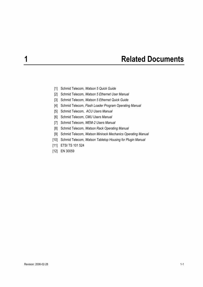
1 Related Documents
[1] Schmid Telecom, Watson 5 Quick Guide [2] Schmid Telecom, Watson 5 Ethernet User Manual [3] Schmid Telecom, Watson 5 Ethernet Quick Guide [4] Schmid Telecom, Flash Loader Program Operating Manual [5] Schmid Telecom, ACU Users Manual [6] Schmid Telecom, CMU Users Manual [7] Schmid Telecom, WEM-2 Users Manual [8] Schmid Telecom, Watson Rack Operating Manual [9] Schmid Telecom, Watson Minirack Mechanics Operating Manual
[10] Schmid Telecom, Watson Tabletop Housing for Plugin Manual [11] ETSI TS 101 524 [12] EN 30059

Revision: 2006-02-28 2-1
2 Watson 5 Overview
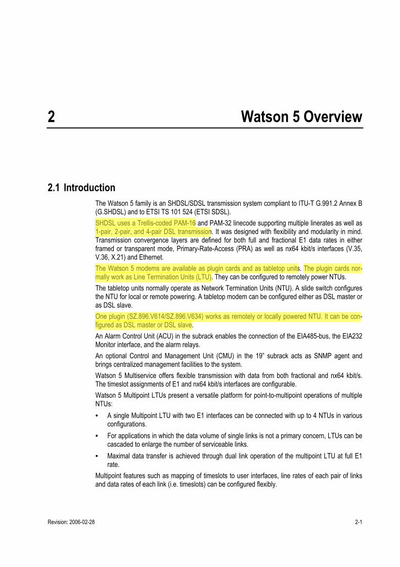
2.1 Introduction The Watson 5 family is an SHDSL/SDSL transmission system compliant to ITU-T G.991.2 Annex B (G.SHDSL) and to ETSI TS 101 524 (ETSI SDSL). SHDSL uses a Trellis-coded PAM-16 and PAM-32 linecode supporting multiple linerates as well as 1-pair, 2-pair, and 4-pair DSL transmission. It was designed with flexibility and modularity in mind. Transmission convergence layers are defined for both full and fractional E1 data rates in either framed or transparent mode, Primary-Rate-Access (PRA) as well as nx64 kbit/s interfaces (V.35, V.36, X.21) and Ethernet. The Watson 5 modems are available as plugin cards and as tabletop units. The plugin cards nor-mally work as Line Termination Units (LTU). They can be configured to remotely power NTUs. The tabletop units normally operate as Network Termination Units (NTU). A slide switch configures the NTU for local or remote powering. A tabletop modem can be configured either as DSL master or as DSL slave. One plugin (SZ.896.V614/SZ.896.V634) works as remotely or locally powered NTU. It can be con-figured as DSL master or DSL slave. An Alarm Control Unit (ACU) in the subrack enables the connection of the EIA485-bus, the EIA232 Monitor interface, and the alarm relays. An optional Control and Management Unit (CMU) in the 19 subrack acts as SNMP agent and brings centralized management facilities to the system. Watson 5 Multiservice offers flexible transmission with data from both fractional and nx64 kbit/s. The timeslot assignments of E1 and nx64 kbit/s interfaces are configurable. Watson 5 Multipoint LTUs present a versatile platform for point-to-multipoint operations of multiple NTUs: • A single Multipoint LTU with two E1 interfaces can be connected with up to 4 NTUs in various
configurations. • For applications in which the data volume of single links is not a primary concern, LTUs can be
cascaded to enlarge the number of serviceable links. • Maximal data transfer is achieved through dual link operation of the multipoint LTU at full E1
rate. Multipoint features such as mapping of timeslots to user interfaces, line rates of each pair of links and data rates of each link (i.e. timeslots) can be configured flexibly.
Watson 5 Plugin/Tabletop/Regenerator Operating Manual
SZ-DOC-W5-1.doc Version 3.0-01
2-2 Revision: 2006-02-28
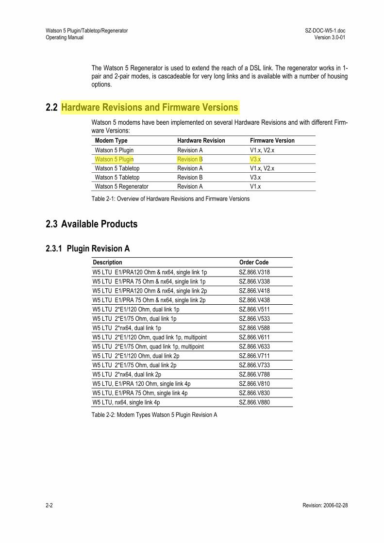
The Watson 5 Regenerator is used to extend the reach of a DSL link. The regenerator works in 1-pair and 2-pair modes, is cascadeable for very long links and is available with a number of housing options.
2.2 Hardware Revisions and Firmware Versions Watson 5 modems have been implemented on several Hardware Revisions and with different Firm-ware Versions:
Modem Type Hardware Revision Firmware Version Watson 5 Plugin Revision A V1.x, V2.x Watson 5 Plugin Revision B V3.x Watson 5 Tabletop Revision A V1.x, V2.x Watson 5 Tabletop Revision B V3.x Watson 5 Regenerator Revision A V1.x
Table 2-1: Overview of Hardware Revisions and Firmware Versions
2.3 Available Products
2.3.1 Plugin Revision A Description Order Code W5 LTU E1/PRA120 Ohm & nx64, single link 1p SZ.866.V318 W5 LTU E1/PRA 75 Ohm & nx64, single link 1p SZ.866.V338 W5 LTU E1/PRA120 Ohm & nx64, single link 2p SZ.866.V418 W5 LTU E1/PRA 75 Ohm & nx64, single link 2p SZ.866.V438 W5 LTU 2*E1/120 Ohm, dual link 1p SZ.866.V511 W5 LTU 2*E1/75 Ohm, dual link 1p SZ.866.V533 W5 LTU 2*nx64, dual link 1p SZ.866.V588 W5 LTU 2*E1/120 Ohm, quad link 1p, multipoint SZ.866.V611 W5 LTU 2*E1/75 Ohm, quad link 1p, multipoint SZ.866.V633 W5 LTU 2*E1/120 Ohm, dual link 2p SZ.866.V711 W5 LTU 2*E1/75 Ohm, dual link 2p SZ.866.V733 W5 LTU 2*nx64, dual link 2p SZ.866.V788 W5 LTU, E1/PRA 120 Ohm, single link 4p SZ.866.V810 W5 LTU, E1/PRA 75 Ohm, single link 4p SZ.866.V830 W5 LTU, nx64, single link 4p SZ.866.V880
Table 2-2: Modem Types Watson 5 Plugin Revision A

SZ-DOC-W5-1.doc Version 3.0-01
Watson 5 Plugin/Tabletop/Regenerator Operating Manual
Revision: 2006-02-28 2-3
2.3.2 Tabletop Revision A Description Order Code W5 NTU E1/PRA 120 Ohm, single link 1p SZ.886.V310 W5 NTU E1/PRA 120 Ohm & nx64, single link 1p SZ.886.V318 W5 NTU E1/PRA 75 Ohm, single link 1p SZ.886.V330 W5 NTU E1/PRA 75 Ohm & nx64, single link 1p SZ.886.V338 W5 NTU nx64, single link 1p SZ.886.V380 W5 NTU E1/PRA/120 Ohm, single link 2p SZ.886.V410 W5 NTU E1/PRA/120 Ohm & nx64, single link 2p SZ.886.V418 W5 NTU E1/PRA/75 Ohm, single link 2p SZ.886.V430 W5 NTU E1/PRA/75 Ohm & nx64, single link 2p SZ.886.V438 W5 NTU nx64, single link 2p SZ.886.V480 W5 NTU E1/PRA/120 Ohm, single link 4p SZ.886.V810 W5 NTU E1/PRA/75 Ohm, single link 4p SZ.886.V830 W5 NTU nx64, single link 4p SZ.886.V880
Table 2-3: Modem Types Watson 5 Tabletop Revision A
2.3.3 Plugin Revision B Description Order Code W5 LTU, 1xE1/120 Ohm, nx64, 1xDSL SZ.866.V118 W5 LTU, 1xE1/75 Ohm, nx64, 1xDSL SZ.866.V138 W5 LTU, 1xE1/120 Ohm, nx64, 2xDSL SZ.866.V218 W5 LTU, 1xE1/75 Ohm, nx64, 2xDSL SZ.866.V238 W5 LTU, 2xE1/120 Ohm, 2 x DSL SZ.866.V512 W5 LTU, 2xE1/75 Ohm, 2 x DSL SZ.866.V532 W5 LTU, 2xnx64, 2xDSL SZ.866.V582 W5 LTU, 2xE1/120 Ohm, 4 x DSL SZ.866.V612 W5 LTU, 2xE1/75 Ohm, 4 x DSL SZ.866.V632 W5 LTU, 2xnx64, 4xDSL SZ.866.V682 W5 LTU, 4xE1/120 Ohm, 4 x DSL SZ.866.V614 W5 LTU, 4xE1/75 Ohm, 4 x DSL SZ.866.V634 W5 NTU, 4xE1/120 Ohm, 4 x DSL SZ.896.V614 W5 NTU, 4xE1/75 Ohm, 4 x DSL SZ.896.V634
Table 2-4: Modem Types Watson 5 Plugin Revision B
Watson 5 Plugin/Tabletop/Regenerator Operating Manual
SZ-DOC-W5-1.doc Version 3.0-01
2-4 Revision: 2006-02-28
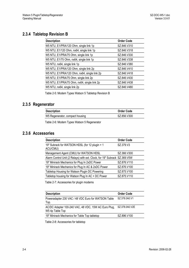
2.3.4 Tabletop Revision B Description Order Code W5 NTU, E1/PRA/120 Ohm, single link 1p SZ.846.V310 W5 NTU, E1/120 Ohm, nx64, single link 1p SZ.846.V318 W5 NTU, E1/PRA/75 Ohm, single link 1p SZ.846.V330 W5 NTU, E1/75 Ohm, nx64, single link 1p SZ.846.V338 W5 NTU, nx64, single link 1p SZ.846.V380 W5 NTU, E1/PRA/120 Ohm, single link 2p SZ.846.V410 W5 NTU, E1/PRA/120 Ohm, nx64, single link 2p SZ.846.V418 W5 NTU, E1/PRA/75 Ohm, single link 2p SZ.846.V430 W5 NTU, E1/PRA/75 Ohm, nx64, single link 2p SZ.846.V438 W5 NTU, nx64, single link 2p SZ.846.V480
Table 2-5: Modem Types Watson 5 Tabletop Revision B
2.3.5 Regenerator Description Order Code W5 Regenerator, compact housing SZ.856.V300
Table 2-6: Modem Types Watson 5 Regenerator
2.3.6 Accessories Description Order Code 19" Subrack for WATSON HDSL (for 12 plugin + 1 ACU/CMU)
SZ.379.V3
Management Agent (CMU) for WATSON HDSL SZ.366.V300 Alarm Control Unit (2 Relays) with ext. Clock, for 19" Subrack SZ.369.V5W 19" Minirack Mechanics for Plug In 2xDC Power SZ.876.V110 19" Minirack Mechanics for Plug In AC & 2xDC Power SZ.876.V100 Tabletop Housing for Watson Plugin DC Powering SZ.875.V100 Tabletop housing for Watson Plug In AC + DC Power SZ.875.V110
Table 2-7: Accessories for plugin modems
Description Order Code Poweradapter 230 VAC / 48 VDC Euro for WATSON Table Top.
SZ.378.0A0.V1
AC/DC Adapter 100-240 VAC, 48 VDC, 15W AC Euro Plug, W5 4p Table Top
SZ.378.0A0.V2E
19" Minirack Mechanics for Table Top tabletop SZ.896.V100
Table 2-8: Accessories for tabletop

SZ-DOC-W5-1.doc Version 3.0-01
Watson 5 Plugin/Tabletop/Regenerator Operating Manual
Revision: 2006-02-28 2-5
Description Order Code Regeneratorcase IP65 for 6 Regenerators SZ.856.V300 SZ.857.V2 Regeneratorcase IP66 for 1 regenerator SZ.856.V300 SZ.859.V1 Regeneratorcase IP68 for 6 Regenerators SZ.856.V300 SZ.859.090.V1
Table 2-9: Accessories for regenerator


Revision: 2006-02-28 3-1
3 Modem Features
3.1 DSL Interface The following configuration options refer to the DSL side and do not affect the user interface operat-ing mode.
3.1.1 Master / Slave To start up a DSL link, one system unit must be configured as master and the other one as slave. The master controls the link start-up procedure. If both system units are configured as master or as slave, no start-up will occur. Usually, the LTU is configured as master and the NTU as slave (default setting). However, it is pos-sible to set up a DSL link with two LTUs or two NTUs, as long as one is configured as master and the other one as slave. In these cases, remote powering is not possible. To configure an LTU as slave it is necessary to set the R/L jumpers located on the PCB in position "RPWR OFF". Gener-ally, the master-slave permissions are: • On a slave unit it is possible to change the local configuration. A slave can neither access nor
modify the master unit's configuration or data. Access to the slave unit's configuration or data is possible via local monitor or via the master unit.
• On a master unit both local and the slave configuration can be modified. For safety reasons the master / slave configuration and the Autorestart option cannot be altered by the master unit over the DSL link.
When the Remote LED on the front panel of the NTU is lit, the system unit is configured as mas-ter.
3.1.2 Linerates and payload rates Watson 5 supports payload bitrates on multiples of 64 kbit/s with the optional use of one Z-bit ac-cording to ETSI TS 101 524. The Z-bit can be configured to add bandwidth for the embedded operating channel (EOC) within the SHDSL overhead. The effective bandwidth of the EOC without the Z-bit is 3.2 kbit/s. The EOC bandwidth is increased to 11.2 kbit/s with the Z-bit.
Note: The additional Z-bit is not supported by the Watson 5 Regenerator. Links with regenerators always have to use 0 Z-bits. Some Watson 5 modems also support m-wire operation on 2, 3 and 4 wire pairs.
Watson 5 Plugin/Tabletop/Regenerator Operating Manual
SZ-DOC-W5-1.doc Version 3.0-01
3-2 Revision: 2006-02-28
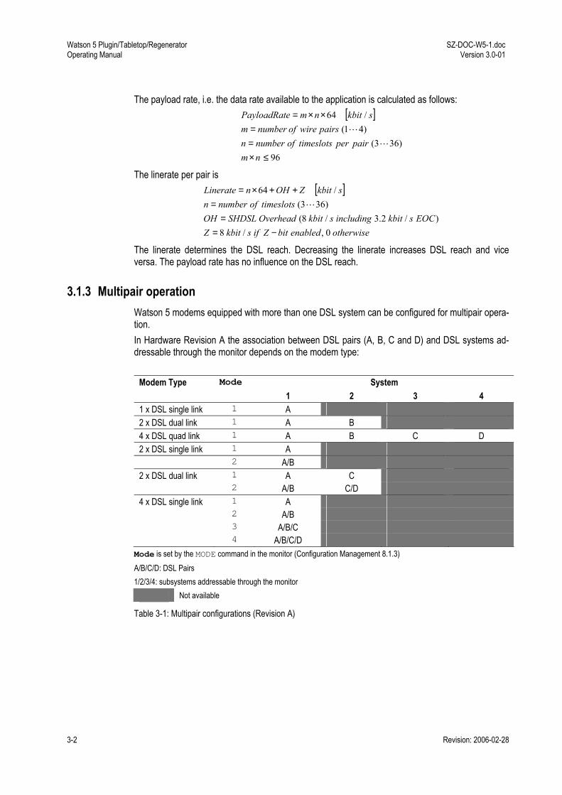
The payload rate, i.e. the data rate available to the application is calculated as follows: [ ]
96)363(
)41(/64
≤×==
××=
nmpairpertimeslotsofnumbern
pairswireofnumbermskbitnmePayloadRat
L
L
The linerate per pair is [ ]
otherwiseenabledbitZifskbitZEOCskbitincludingskbitOverheadSHDSLOH
timeslotsofnumbernskbitZOHnLinerate
0,/8)/2.3/8(
)363(/64
−==
=++×=
L
The linerate determines the DSL reach. Decreasing the linerate increases DSL reach and vice versa. The payload rate has no influence on the DSL reach.
3.1.3 Multipair operation Watson 5 modems equipped with more than one DSL system can be configured for multipair opera-tion. In Hardware Revision A the association between DSL pairs (A, B, C and D) and DSL systems ad-dressable through the monitor depends on the modem type:
Modem Type Mode System 1 2 3 4 1 x DSL single link 1 A 2 x DSL dual link 1 A B 4 x DSL quad link 1 A B C D 2 x DSL single link 1 A 2 A/B 2 x DSL dual link 1 A C 2 A/B C/D 4 x DSL single link 1 A 2 A/B 3 A/B/C 4 A/B/C/D Mode is set by the MODE command in the monitor (Configuration Management 8.1.3) A/B/C/D: DSL Pairs 1/2/3/4: subsystems addressable through the monitor
Not available
Table 3-1: Multipair configurations (Revision A)
SZ-DOC-W5-1.doc Version 3.0-01
Watson 5 Plugin/Tabletop/Regenerator Operating Manual
Revision: 2006-02-28 3-3
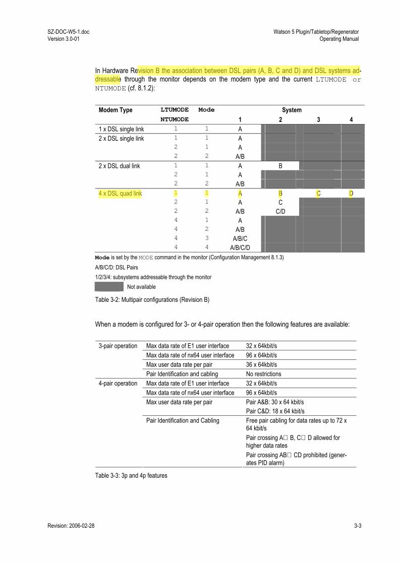
In Hardware Revision B the association between DSL pairs (A, B, C and D) and DSL systems ad-dressable through the monitor depends on the modem type and the current LTUMODE or NTUMODE (cf. 8.1.2):
Modem Type LTUMODE Mode System NTUMODE 1 2 3 4 1 x DSL single link 1 1 A 2 x DSL single link 1 1 A 2 1 A 2 2 A/B 2 x DSL dual link 1 1 A B 2 1 A 2 2 A/B 4 x DSL quad link 1 1 A B C D 2 1 A C 2 2 A/B C/D 4 1 A 4 2 A/B 4 3 A/B/C 4 4 A/B/C/D Mode is set by the MODE command in the monitor (Configuration Management 8.1.3) A/B/C/D: DSL Pairs 1/2/3/4: subsystems addressable through the monitor
Not available
Table 3-2: Multipair configurations (Revision B)
When a modem is configured for 3- or 4-pair operation then the following features are available:
Max data rate of E1 user interface 32 x 64kbit/s Max data rate of nx64 user interface 96 x 64kbit/s Max user data rate per pair 36 x 64kbit/s
3-pair operation
Pair Identification and cabling No restrictions Max data rate of E1 user interface 32 x 64kbit/s Max data rate of nx64 user interface 96 x 64kbit/s Max user data rate per pair Pair A&B: 30 x 64 kbit/s
Pair C&D: 18 x 64 kbit/s
4-pair operation
Pair Identification and Cabling Free pair cabling for data rates up to 72 x 64 kbit/s Pair crossing A⇔B, C⇔D allowed for higher data rates Pair crossing AB⇔CD prohibited (gener-ates PID alarm)
Table 3-3: 3p and 4p features

Watson 5 Plugin/Tabletop/Regenerator Operating Manual
SZ-DOC-W5-1.doc Version 3.0-01
3-4 Revision: 2006-02-28
3.1.4 DSL Clocking options Watson 5 has a crystal controlled DSL clock that does not depend on the clocking of the user inter-face signals. Data rate adaptation between the user interface signal clock and the DSL clock is achieved by stuffing / deleting bits in the DSL frames (plesiochronous operation). Watson 5 supports clock mode 1 of [11]. With hardware Revision B and firmware version 3.x clock mode 2 is available. Table 2-1 taken from [11] shows the clock modes available in Watson 5.
Mode Num-ber
STU-C Symbol Clock Reference
STU-R Symbol Clock Reference
Example Application Mode
1 Local oscillator Received symbol clock "Classic" HDSL. Plesiochronous 2 Network reference
clock Received symbol clock "Classic" HDSL with
embedded timing reference.
Plesiochronous with timing refer-ence
Table 3-4: DSL Clock Modes
If the E1 signals use the same Network reference clock as the DSL then no additional Wander is generated in Clock mode 2 by the DSL transmission. This is especially useful for low linerates. An external DSL Clock input is available on the Watson subrack and minirack mechanics.
3.1.5 Power Backoff In order to reduce ingress on other transmission systems operating on adjacent pairs bundled in the same cable, the transmit power of LTU and/or NTU can be decreased by activating the power back-off mode. With enabled power back-off the transmit power will be reduced adaptively in function of the esti-mated cable attenuation:
Estimated Power Loss(*) Power Backoff < 1 dB 6 dB < 2 dB 5 dB < 3 dB 4 dB < 4 dB 3 dB < 5 dB 2 dB < 6 dB 1 dB ≥ 6 dB no backoff
(*) Calculated as Tx Power Estimated Rx Power
Table 3-5: Power Backoff
Notes: • Power backoff can be configured individually for LTU and NTU. • Power backoff is not available on the Watson 5 Regenerator..

SZ-DOC-W5-1.doc Version 3.0-01
Watson 5 Plugin/Tabletop/Regenerator Operating Manual
Revision: 2006-02-28 3-5
3.1.6 Symmetric and Asymmetric PSD Mask For linerates of 2'056 kbit/s and 2'312 kbit/s the Power Spectral Density (PSD) masks of LTU and NTU can be switched into symmetric or asymmetric mode. Activating asymmetrical PSD masks will increase upstream transmit power (NTU ! LTU). This im-proves near-end crosstalk (NEXT) at the LTU side and will increase the possible loop length in cases where many DSL links have to share the same cable e.g. coming out of a central office.
Note: Asymmetric PSD operation is only possible with zero Z-bits.
3.1.7 Wetting Current The remote powering circuit of an LTU can be used to inject a wetting current on the DSL link: • To use wetting current enable remote powering by configuration (POWER ON) and use local
powering for the NTU. • For LTUs Hardware Revision A you have to set the R/L jumper on the LTU in position RPWR
ON. If the R/L jumper on the LTU is set to position RPWR OFF then no wetting current will be injected on the loop.
The NTUs will sink wetting current as per Table 3-6. This table shows the currents drawn in single pair operation. In multipair mode the wetting current is distributed equally between the pairs.
Unit Wetting Current NTU Revision A 0.30 mA NTU Revision B 2.5 mA NTU Plugin (SZ.896) 5 mA Regenerator No wetting current LTU in DSL slave mode No wetting current
Table 3-6: Wetting Current per pair
Note that on NTUs Revision B and the Plugin NTU the wetting current sink can be enabled/disabled with the WETTING monitor command, cf. 8.1.3
3.2 E1 Interface
3.2.1 Framing
Transparent Mode In transparent mode, the E1 signal is transmitted without any changes, whereas in framed mode, the frame / multiframe alignment words and CRC4 bits are regenerated by the E1 framer. The CRC4 and E-bit Insertion options are not relevant in transparent mode.
Framed Mode ITU-T G.704 In framed mode (framing according to ITU-T G.704), the E1 stream passes through an E1 framer before entering the DSL section, and the E1 stream received from the DSL section first passes through the E1 framer before being transmitted to the E1 network.

Watson 5 Plugin/Tabletop/Regenerator Operating Manual
SZ-DOC-W5-1.doc Version 3.0-01
3-6 Revision: 2006-02-28
The E1 framer operates in Common Channel Signaling (CCS) mode. Timeslot 16 and all national bits are fully transparent. Consider the CRC4 and E-bit Insertion options when operating in framed mode. CRC4 If operating in framed mode, the CRC4 option can be used to adapt to specific E1 network re-quirements: • If enabled, the E1 framer synchronizes on CRC4 multiframes and CRC4 errors are reported. In
the outgoing E1 signal the framer generates the CRC4 multiframe alignment and checksum words. The A-Bit and the Sa-Bits pass transparently.
• If disabled, the international bits are set to 1 in the outgoing E1 signal. All national bits are fully transparent. On the receive side, the E1 framer synchronizes on basic frames only and no CRC4 errors are reported.
E-bit Insertion • If automatic E-Bit generation is enabled, detected CRC4 errors will cause the assertion of the
E-bits. • If disabled, all E-Bits are set to 1.
3.2.2 AIS Detection If AIS detection is enabled, receiving AIS from the E1 side causes the following actions: • The Non-Urgent alarm is activated (AIS-S). • AIS is transmitted to the remote station by sending AIS-R over the DSL With AIS detection disabled AIS from the E1 interface is ignored.
3.2.3 AIS Generation If this option is enabled, AIS is sent over the local E1 interface if • the DSL link to the remote station is not established (loss of signal or loss of frame alignment
on DSL side) or • the remote station is sending AIS-R. If AIS generation is disabled, no signal is transmitted on the E1 side. The E1 interface will be switched off if either of these two conditions arises. AIS Generation can also be set to transparent: in this mode AIS is sent on the local E1 interface if AIS is signaled from the remote interface (reception of AIS-R). The local E1 interface is switched off if the DSL link looses synchronization.
SZ-DOC-W5-1.doc Version 3.0-01
Watson 5 Plugin/Tabletop/Regenerator Operating Manual
Revision: 2006-02-28 3-7
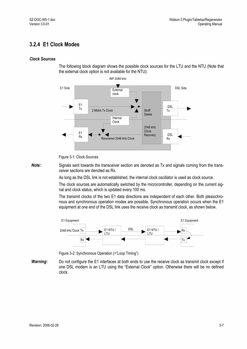
3.2.4 E1 Clock Modes
Clock Sources The following block diagram shows the possible clock sources for the LTU and the NTU (Note that the external clock option is not available for the NTU):
Externalclock
DSLTx
DSLRxRecovered 2048 kHz Clock
2 Mbit/s Tx Clock
INP 2048 kHz
E1 Side DSL Side
E1Tx
E1Rx
InternalClock
2048 kHzClock-Recovery
Stuff/Delete
Figure 3-1: Clock Sources
Note: Signals sent towards the transceiver section are denoted as Tx and signals coming from the trans-ceiver sections are denoted as Rx. As long as the DSL link is not established, the internal clock oscillator is used as clock source. The clock sources are automatically switched by the microcontroller, depending on the current sig-nal and clock status, which is updated every 100 ms. The transmit clocks of the two E1 data directions are independent of each other. Both plesiochro-nous and synchronous operation modes are possible. Synchronous operation occurs when the E1 equipment at one end of the DSL link uses the receive clock as transmit clock, as shown below.
E1 NTU /LTU
Tx
Rx
2048 kHz Clock
E1 Equipment
DSL
Tx
Rx
E1 Equipment
E1 NTU /LTU
Figure 3-2: Synchronous Operation (=Loop Timing)
Warning: Do not configure the E1 interfaces at both ends to use the receive clock as transmit clock except if one DSL modem is an LTU using the External Clock option. Otherwise there will be no defined clock.
Watson 5 Plugin/Tabletop/Regenerator Operating Manual
SZ-DOC-W5-1.doc Version 3.0-01
3-8 Revision: 2006-02-28
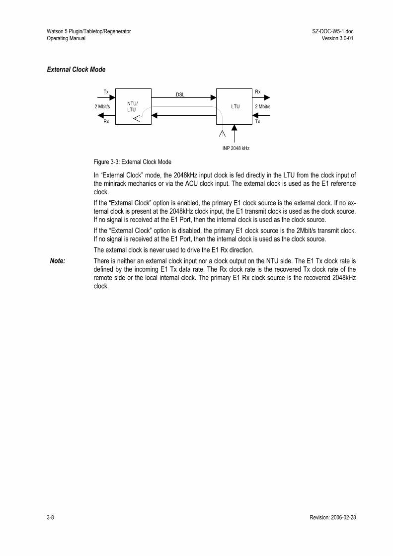
External Clock Mode
NTU/LTU LTU
DSLTx
Rx
Rx
Tx
2 Mbit/s2 Mbit/s
INP 2048 kHz Figure 3-3: External Clock Mode
In External Clock mode, the 2048kHz input clock is fed directly in the LTU from the clock input of the minirack mechanics or via the ACU clock input. The external clock is used as the E1 reference clock. If the External Clock option is enabled, the primary E1 clock source is the external clock. If no ex-ternal clock is present at the 2048kHz clock input, the E1 transmit clock is used as the clock source. If no signal is received at the E1 Port, then the internal clock is used as the clock source. If the External Clock option is disabled, the primary E1 clock source is the 2Mbit/s transmit clock. If no signal is received at the E1 Port, then the internal clock is used as the clock source. The external clock is never used to drive the E1 Rx direction.
Note: There is neither an external clock input nor a clock output on the NTU side. The E1 Tx clock rate is defined by the incoming E1 Tx data rate. The Rx clock rate is the recovered Tx clock rate of the remote side or the local internal clock. The primary E1 Rx clock source is the recovered 2048kHz clock.
SZ-DOC-W5-1.doc Version 3.0-01
Watson 5 Plugin/Tabletop/Regenerator Operating Manual
Revision: 2006-02-28 3-9
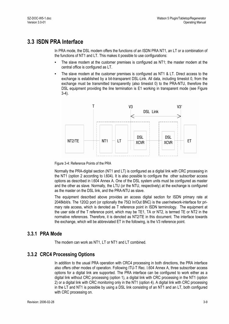
3.3 ISDN PRA Interface In PRA mode, the DSL modem offers the functions of an ISDN PRA NT1, an LT or a combination of the functions of NT1 and LT. This makes it possible to use configurations: • The slave modem at the customer premises is configured as NT1; the master modem at the
central office is configured as LT. • The slave modem at the customer premises is configured as NT1 & LT. Direct access to the
exchange is established by a bit-transparent DSL-Link. All data, including timeslot 0, from the exchange must be transmitted transparently (also timeslot 0) to the PRA-NTU, therefore the DSL equipment providing the line termination is E1 working in transparent mode (see Figure 3-4).
NT2/TE NT1 LT ETDSL XCVR
DSLXCVR
T V3 V3' DSL Link
Figure 3-4: Reference Points of the PRA
Normally the PRA-digital section (NT1 and LT) is configured as a digital link with CRC processing in the NT1 (option 2 according to I.604). It is also possible to configure the other subscriber access options as described in I.604 Annex A. One of the DSL system units must be configured as master and the other as slave. Normally, the LTU (or the NTU, respectively) at the exchange is configured as the master on the DSL link, and the PRA-NTU as slave. The equipment described above provides an access digital section for ISDN primary rate at 2048kbit/s. The 120Ω port (or optionally the 75Ω In/Out BNC) is the user/network-interface for pri-mary rate access, which is denoted as T reference point in ISDN terminology. The equipment at the user side of the T reference point, which may be TE1, TA or NT2, is termed TE or NT2 in the normative references. Therefore, it is denoted as NT2/TE in this document. The interface towards the exchange, which will be abbreviated ET in the following, is the V3 reference point.
3.3.1 PRA Mode The modem can work as NT1, LT or NT1 and LT combined.
3.3.2 CRC4 Processing Options In addition to the usual PRA operation with CRC4 processing in both directions, the PRA interface also offers other modes of operation. Following ITU-T Rec. I.604 Annex A, three subscriber access options for a digital link are supported. The PRA interface can be configured to work either as a digital link without CRC processing (option 1), a digital link with CRC processing in the NT1 (option 2) or a digital link with CRC monitoring only in the NT1 (option 4). A digital link with CRC processing in the LT and NT1 is possible by using a DSL link consisting of an NT1 and an LT, both configured with CRC processing on.

Watson 5 Plugin/Tabletop/Regenerator Operating Manual
SZ-DOC-W5-1.doc Version 3.0-01
3-10 Revision: 2006-02-28
Digital Link without CRC Processing (Option 1) In this mode, transparent transmission between the ET and the NT2/TE is possible. There is no CRC4 processing in the PRA-NTU; the CRC processing is only done in the ET and the NT2/TE. When loss of incoming signal is detected on either side, AIS is transmitted to the opposite side. The detection of events and the state information are still valid as in normal PRA operation mode (option 2). Depending on the distribution of NT1 and LT functionality, two configurations are possible for option 1: • The master is E1 configured transparent, AIS-generation on and AIS-detection off; the slave is
PRA NT1 & LT, CRC4 processing off. • The master is PRA LT with CRC4 processing off; the slave is PRA NT1 with CRC4 processing
off.
Note: For proper operation in Option 1, the equipment at the customer side (NT2) and at the central office side (ET) must be in CRC4 framed mode.
LRMG
Local CRC error informationRemote CRC error informationCRC MonitorCRC Generator
Optional
Mandatory
Digital Link
T V3'
M
G
G
M
NT2 ET
R
L
L
R
RX
TX
TX
RX
Figure 3-5: Digital Link without CRC Processing

SZ-DOC-W5-1.doc Version 3.0-01
Watson 5 Plugin/Tabletop/Regenerator Operating Manual
Revision: 2006-02-28 3-11
Digital Link with CRC Processing in the NT1 (Option 2) This is the usual PRA operating mode as described in ETS 300 233 and ITU-T Rec. G.962 Annex B. The PRA interface is intended to be used in this mode.
LRMG
Local CRC error informationRemote CRC error informationCRC MonitorCRC Generator
Optional
Mandatory
Digital Link
NT2
G
M
ET
L
R
R
L
T V3'
NT1 LT
L R
L
R
G
M G
M
M
G
RX
TX
Figure 3-6: Digital Link with CRC Processing in the NT1
CRC4 is generated towards the NT2/TE and towards the ET and monitored at both sides of the NT1. When a block with a CRC4 error is received from the NT2/TE, CRC4 error information is transmitted towards the NT2/TE (via E-bits) and optionally towards the ET (via Sa6-bits). When a block with a CRC4 error is received from the ET, error information is transmitted towards the ET (via E-bits). CRC4 errors detected at the T reference point of the NT2/TE are reported to the NT1 (via E-bits) and optionally towards the ET (via Sa6-bits). CRC4 errors detected at the V3 reference point of the ET are reported to the NT1 (via E-bits). Loopback 1 and 2 control facilities and monitor-ing of defect conditions are implemented according to ETS 300 233. Depending on the distribution of NT1 and LT functionality, two set-ups are possible for option 2: • The master is E1 configured transparent, AIS-generation on and AIS-detection off; the slave is
PRA NT1 & LT, CRC4 processing on. • The master is PRA LT with CRC4 monitoring on; the slave is PRA NT1 with CRC4 processing
on.
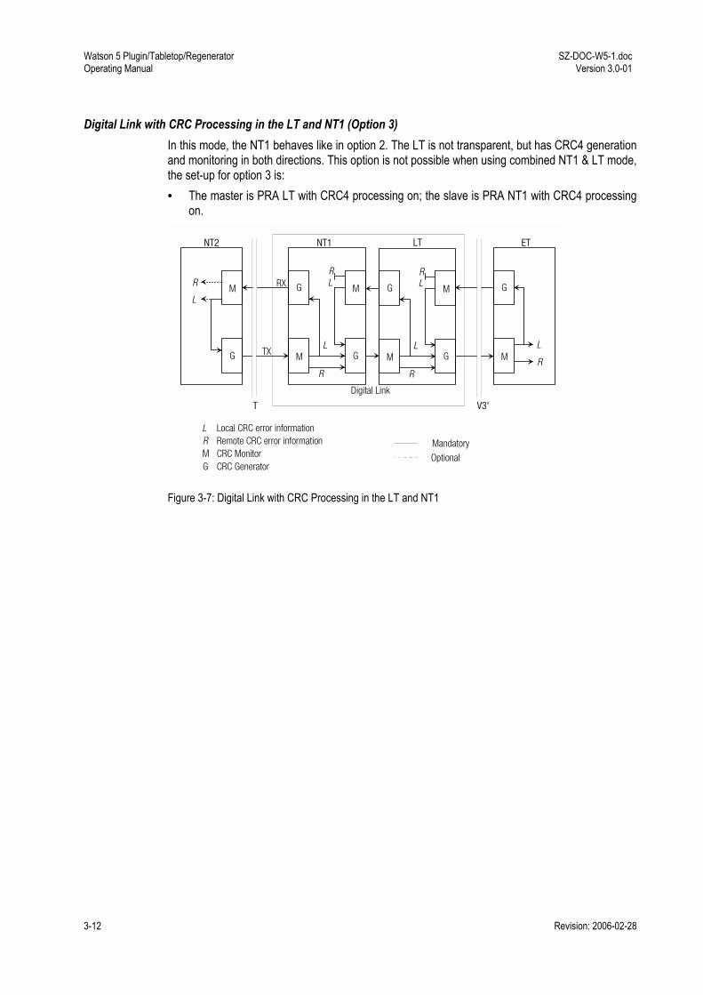
Watson 5 Plugin/Tabletop/Regenerator Operating Manual
SZ-DOC-W5-1.doc Version 3.0-01
3-12 Revision: 2006-02-28
Digital Link with CRC Processing in the LT and NT1 (Option 3) In this mode, the NT1 behaves like in option 2. The LT is not transparent, but has CRC4 generation and monitoring in both directions. This option is not possible when using combined NT1 & LT mode, the set-up for option 3 is: • The master is PRA LT with CRC4 processing on; the slave is PRA NT1 with CRC4 processing
on.
LRMG
Local CRC error informationRemote CRC error informationCRC MonitorCRC Generator
Optional
Mandatory
Digital Link
NT2
G
M
ET
L
R
R
L
T V3'
NT1 LT
L R
L
R
G
M G
M
M
G
RX
TX
L R
L
R
G
M G
M
Figure 3-7: Digital Link with CRC Processing in the LT and NT1

SZ-DOC-W5-1.doc Version 3.0-01
Watson 5 Plugin/Tabletop/Regenerator Operating Manual
Revision: 2006-02-28 3-13
Digital Link with CRC Monitoring in the NT1 (Option 4) CRC4 multiframe alignment and checksum words are not regenerated in both directions, i.e. data will be transmitted without changes in both directions. However, blocks with CRC4 errors received from the NT2/TE and the ET will be detected and monitored by the G.826 performance manage-ment functions of the NTU monitor. When loss of signal or loss of frame alignment is detected at either side, AIS is transmitted at the opposite side. The detection of events and the state information are still valid as in normal PRA operation mode (option 4).
LRMG
Local CRC error informationRemote CRC error informationCRC MonitorCRC Generator Optional
Mandatory
SNSU
Storage for network side monitorStorage for user side monitor
M
Digital Link
NT2
G
M
ET
L
R
R
L
T V3'
NT1 LT
M
M
G
SNSU
RX
TX
Figure 3-8: Digital Link with CRC Monitoring in the NT1
Depending on the distribution of NT1 and LT functionality, two configurations are possible for option 1: • The master is E1 configured transparent, AIS-generation on and AIS-detection off; the slave is
PRA NT1 & LT, CRC4 monitoring on. • The master is PRA LT with CRC4 processing off; the slave is PRA NT1 with CRC4 monitoring
on.
3.3.3 Generation of CRC4 Error Notifications to the ET For enhanced maintenance capabilities, CRC4 errors detected at the interface at the T reference point may optionally be reported to the ET (see ETS 300 233 section 8.3 and table 4 of ITU-T Rec. G.962 section B.5 and table B.2). CRC block errors detected at the T reference point of the NT1 and CRC error indications received from the NT2/TE in the E-bits are reported to the ET using the Sa6-bits. An ET applying asynchronous detection of the Sa6-bits (no synchronization of the Sa6-bits to the sub-multiframe) will mistake such CRC4 error reports from the NT1 for other errors, e.g. loss of power at NT1 or FC4. To avoid this it is possible to disable Sa6-bit indication. If the CRC4 error notification in Sa6 is enabled, Sa6=0001 indicates an E-bit received from the NT2/TE, Sa6=0010 indicates a CRC4 error detected at the T reference point of the NT1, and Sa6=0011 indicates the simultaneous occurrence of both errors.
Watson 5 Plugin/Tabletop/Regenerator Operating Manual
SZ-DOC-W5-1.doc Version 3.0-01
3-14 Revision: 2006-02-28
If disabled, Sa6 is always 0000 in normal operation state. As sending of Sa-bits requires regeneration of the CRC4 frames in the NT1, this option is only acti-vated when option 2 (Digital link with CRC processing in the NT1) is selected.
3.4 nx64 kbit/s Interface
3.4.1 Features • The nx64 kbit/s interface is software-configurable between V.35, V.36 and X.21. • The bitrate can be selected in steps of 64kbit/s from 64kbit/s (n=1) up to 2304kbit/s (n=36, sin-
gle pair systems), up to 4608 kbit/s (n=72, 2-pair systems) and up to 6144 kbit/s (n=96, 4-pair system).
• Independent receive and transmit clocks for V.35 and V.36. • Transmit clock is configurable either co-directional (clock defined by user equipment connected
to nx64 Port) or contra-directional (clock generated from internal reference of from receiving clock).
• Detection for loss of clock and clock rate mismatch in co-directional clock mode. • Standard SubD25 connector (ISO 2110 for V.35, RS-530 for V.36, proprietary for X.21) for
DCE operation, other connectors (ISO 2593 for V.35, ISO 4902 for V.36, ISO 4903 for X.21) both for operation as DCE or DTE are available by means of adapters.
• Loop 1 and Loop 2 supported, for V.35 and V.36 they can also be controlled by circuits 140 (RL) and 141 (LL), according to V.54.
• Support for byte timing (circuit B) in X.21 mode. • Activity indication of nx64 kbit/s interface on front LED of tabletop if operated as DSL slave • Multiservice operation: it is possible to use nx64 kbit/s and an E1 user interfaces simultane-
ously, sharing share the DSL bitrate between them.
3.4.2 User Interface Type The interface mode can be set to V.35, V.36 or X.21.

SZ-DOC-W5-1.doc Version 3.0-01
Watson 5 Plugin/Tabletop/Regenerator Operating Manual
Revision: 2006-02-28 3-15
3.4.3 Bitrates The maximum bitrates depend on the number of pairs and the combination of NTUs and LTUs as shown in Figure 3-9:
4.6 Mbps72 TS
4.6 Mbps
Disabled
2.3 Mbps
2.3 Mbps
NTU 2p
2.3 Mbps36 TS
36x64kbps per pair
18x64kbps per pair
18x64kbps per pair
2.6 Mbps36x64kbps per pair
2 Mbps
SingleLink Multiservice
LTU
2.6 Mbps40 TS (*)
2 Mbps32 TS
max. 32x64kbps perpair6.14 Mbps
96 TS 6.14 Mbps
(*) If TS0 is not transferred (MP 0, MP 2), 41 TS areavailable for nx64interface.
NTU 4p
NTU 2p
NTU 2p
NTU 2p
SingleLink Multiservice
LTU
Dual LinkLTU 2p
singleLink LTU4p in 3pmode
2.3 Mbps36 TS
n x 64
E1
n x 64
E1
n x 64
n x 64
n x 64
E1
n x 64
n x 64
n x 64
n x 64
n x 64
Figure 3-9: nx64 bitrate combinations
• Dual LTU nx64 - NTU nx64, single pair link: the bitrate can be selected in the range of 64 kbit/s up to 2304 kbit/s.
• Multiservice LTU E1&nx64 - NTU nx64 or NTU nx64 - NTU nx64 link, two-pair link: the bitrate can be selected in the range from 128 kbit/s to 4608 kbit/s in steps of 64kbit/s (n = 2..72).
• LTU nx64 NTU nx64, 4-pair link: the bitrate can be selected in the range from 256 kbit/s to 6144 kbit/s in steps of 64kbit/s (n = 4..96).
3.4.4 V.54 Loops and Loop Control As the X.21 interface provides only the control interchange circuits C and I, most of the features de-scribed afterwards are only applicable for V.35 and V.36, but not for X.21.

Watson 5 Plugin/Tabletop/Regenerator Operating Manual
SZ-DOC-W5-1.doc Version 3.0-01
3-16 Revision: 2006-02-28
3.4.5 Handshake Operation When no loopback is established, the control circuits perform this handshake protocol: • 105 (RTS Request to send; X.21: C): Input from DTE. For X.21, C = OFF will cause a DTR
alarm. • 106 (CTS Ready for sending, X.21: I):
if Handshake option enabled: is set ON when a DSL connection is established and 105 = ON is detected. if Handshake option disabled: is set ON when a DSL connection is established
• 107 (DSR Data set ready): is set ON when a DSL connection is established • 108 (DTR Data terminal ready): input from DTE. For V.35 and V.36, 108 = OFF will cause a
DTR alarm. • 109 (RLSD Data channel received line signal detector): is set ON when a DSL connection is
established. • 140 (RL Loopback / Maintenance test): Input from DTE; will be set OFF in normal mode. • 141 (LL Local loopback): input from DTE; will be set OFF in normal mode. • 142 (TM Test indicator): is set OFF in normal mode.
3.4.6 Supported V.54 Loops ITU-T recommendation V.54 defines four test loops. Loops 2 and 3 correspond to DSL loopbacks 2 and 1. The interchange circuits are set in the following way: • V.54 Loop 3 Local loop established in the DCE, i.e. DSL loopback 1 in an nx64 kbit/s NTU/LTU. These output in-terchange circuits are set: 107 = ON and 142 = ON • V.54 Loop 2 Loop in remote DCE, i.e. DSL loopback 2 in the remote (slave) NTU/LTU. These output interchange circuits are set:
Master: 107 = ON and 142 = ON Slave: 104 (received data) = 1, 106 = OFF, 107 = OFF, 109 = OFF and 142 = ON.
3.4.7 Automatic Loop Control through the DTE/DCE Interface Automatic control through the interface is achieved by using circuits 140 and 141: • 140 = ON and 141 = OFF ⇒ V.54 loop 2 (DSL loopback 2) • 140 = OFF and 141 = ON ⇒ V.54 loop 3 (DSL loopback 1) This automatic loop control can be switched on/off using the V54LOOPS configuration option. The interface on the user side can be a DTE or a DCE. To connect them to the interface port, the V.35 DTE or V.35 DCE cable must be used.

SZ-DOC-W5-1.doc Version 3.0-01
Watson 5 Plugin/Tabletop/Regenerator Operating Manual
Revision: 2006-02-28 3-17
3.4.8 Clock Polarity In X.21 mode the sampling instant for the incoming data stream on circuit T of the user interface (UIF) can be switched to rising or falling slope of the contradirectional clock circuit S. Data transitions of the received data on UIF circuit R are not influenced by this setting. In default configuration "normal" circuit T is sampled on rising edge of clock S. The data transitions on T and R occur at the OFF to ON transition of S (according X.24 standard). The ON to OFF tran-sition of circuit S nominally indicates the center of each signal element, in this case on circuit R. When Clock Polarity is set to "inverted", circuit T is sampled with the falling slope of S. The incom-ing data at X.21 circuit T will be sampled at the OFF to ON transition of S.
3.4.9 Byte Timing In the X.21 mode, the byte timing circuit B according to X.24 can be activated (configuration option BYTETIMING). As the circuits B (byte timing) and X (co-directional transmit clock) share the same pins on the 15-pin ISO 4903 connector, separate cables have to be used for these cases.
3.4.10 Multiservice / nx64 Clock Modes For V.35 and V.36, the receiving and the transmitting clock are independent. The receiving clock is always the recovered remote clock. The clock mode configuration only applies to the transmit clock. For X.21, there is only one clock (circuit S) to receive and transmit, the clock mode determines the source of that single clock; however, in the co-directional nx64 Port clock mode, X is used as a co-directional transmit clock and S is used only as receive clock. In the following section the clock which can be selected by the clock mode is denoted as transmit clock. In most cases the clock mode determines whether the transmit clock is co-directional or contra-directional. The following clock modes are possible: • nx64 Port: The transmitting clock is the co-directional clock coming from the equipment con-
nected to the nx64 port (circuit 113, X). • E1 Port: The transmitting clock is generated by the transmit clock used at the E1 port. The
2048kHz E1 clock is fractionally synthesized to the bitrate configured and available at the con-tra-directional transmit clock output (circuit 114). This clock mode should be used for multiser-vice operation (simultaneous use of E1 and nx64 kbit/s).
• Internal: The transmitting clock is generated from the internal reference clock (contra-directional, circuit 114).
• Remote: The transmitting clock is the recovered remote clock, i.e. the same clock as the re-ceiving clock (115) at the V.35 and V.36 interface (contra-directional, circuit 114).
The clock mode to be used depends on the individual network configuration: • nx64 kbit/s - nx64 kbit/s connection: First, it should be checked whether the equipment con-
nected to the nx64 port uses a transmitting clock output or input. In the first case, the co-directional nx64 port mode can be used. In the latter case, one of the contra-directional clock modes should be used. The internal clock mode should be suitable in most cases, the remote clock can be used if the receive and transmit clocks have to be equal. As the contra-directional X.21 clock modes use only one clock the following configurations are possible: nx64 port - nx64 port, nx64 port - remote, internal - remote.
• nx64 kbit/s - E1 connection: The clock mode can be selected as in the previous case.

Watson 5 Plugin/Tabletop/Regenerator Operating Manual
SZ-DOC-W5-1.doc Version 3.0-01
3-18 Revision: 2006-02-28
It is recommended to have at least one clock reference. So one should not use remote clock mode at both ends. You should not choose remote clock mode either if the remote modem is E1 and the E1 equipment connected to the remote E1 port uses loop timing (i.e. it uses the received clock as transmit clock).
3.4.11 Clock Direction For V.35 and V.36 interface types, the clock direction can be configured by the user. If codirec-tional, Transmit Data 103 is sampled with Transmit Clock 113. If contradirectional, Transmit Data 103 is sampled with Transmit Clock 114. It is recommended to use codirectional transmit timing whenever possible, in particular for bitrates > 32 x 64 kbit/s.
3.5 Timeslot Mapping Generally, the user interface timeslots are mapped onto the DSL frame according to ETSI TS 101 524. The timeslots of the user interfaces are linearly mapped to the B-channels of the DSL and vice versa. The number of timeslots n from the user interface(s) must be less or equal the number of B-channels (N). Unused B-channels are filled with all ones. After startup, the complete mapping information is exchanged between LTU and NTU. Additionally, special mapping modes can be selected by configuration in order to make best use of the available DSL bandwidth for the respective application.
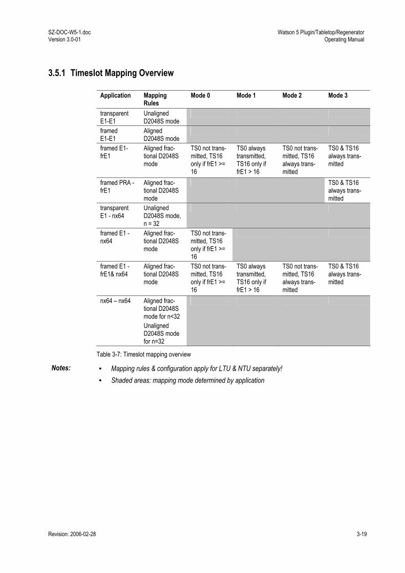
SZ-DOC-W5-1.doc Version 3.0-01
Watson 5 Plugin/Tabletop/Regenerator Operating Manual
Revision: 2006-02-28 3-19
3.5.1 Timeslot Mapping Overview
Application Mapping Rules
Mode 0 Mode 1 Mode 2 Mode 3
transparent E1-E1
Unaligned D2048S mode
framed E1-E1
Aligned D2048S mode
framed E1- frE1
Aligned frac-tional D2048S mode
TS0 not trans-mitted, TS16 only if frE1 >= 16
TS0 always transmitted, TS16 only if frE1 > 16
TS0 not trans-mitted, TS16 always trans-mitted
TS0 & TS16 always trans-mitted
framed PRA - frE1
Aligned frac-tional D2048S mode
TS0 & TS16 always trans-mitted
transparent E1 - nx64
Unaligned D2048S mode, n = 32
framed E1 - nx64
Aligned frac-tional D2048S mode
TS0 not trans-mitted, TS16 only if frE1 >= 16
framed E1 - frE1& nx64
Aligned frac-tional D2048S mode
TS0 not trans-mitted, TS16 only if frE1 >= 16
TS0 always transmitted, TS16 only if frE1 > 16
TS0 not trans-mitted, TS16 always trans-mitted
TS0 & TS16 always trans-mitted
nx64 nx64 Aligned frac-tional D2048S mode for n<32 Unaligned D2048S mode for n=32
Table 3-7: Timeslot mapping overview
Notes: • Mapping rules & configuration apply for LTU & NTU separately! • Shaded areas: mapping mode determined by application
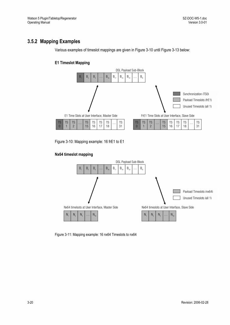
Watson 5 Plugin/Tabletop/Regenerator Operating Manual
SZ-DOC-W5-1.doc Version 3.0-01
3-20 Revision: 2006-02-28
3.5.2 Mapping Examples Various examples of timeslot mappings are given in Figure 3-10 until Figure 3-13 below: E1 Timeslot Mapping
FrE1 Time Slots at User Interface, Slave Side E1 Time Slots at User Interface, Master Side
TS0
TS1
TS2
… TS31
TS17
… TS16
TS18
TS 15
DSL Payload Sub-Block
B1 B2 B3 … BN B18… B17 B19B16
Unused Timeslots (all 1)
Payload Timeslots (frE1)
Synchronization (TS0)
TS0
TS1
TS2
… TS31
TS17
… TS16
TS18
TS 15
Figure 3-10: Mapping example: 16 frE1 to E1 Nx64 timeslot mapping
Nx64 timeslots at User Interface, Slave Side Nx64 timelsots at User Interface, Master Side
N1 N2 N3 … N16
DSL Payload Sub-Block
B1 B2 B3 … BN B18… B17 B19B16
Unused Timeslots (all 1)
Payload Timeslots (nx64)
N1 N2 N3 … N16
Figure 3-11: Mapping example: 16 nx64 Timeslots to nx64
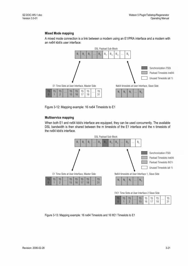
SZ-DOC-W5-1.doc Version 3.0-01
Watson 5 Plugin/Tabletop/Regenerator Operating Manual
Revision: 2006-02-28 3-21
Mixed Mode mapping A mixed mode connection is a link between a modem using an E1/PRA interface and a modem with an nx64 kbit/s user interface:
E1 Time Slots at User Interface, Master Side
TS0
TS1
TS2
… TS31
TS17
… TS16
TS18
TS 15
DSL Payload Sub-Block
B1 B2 B3 … BN B18… B17 B19B16
Unused Timeslots (all 1)
Synchronization (TS0)
Nx64 timeslots at User Interface, Slave Side
N1 N2 N3 … N16
Payload Timeslots (nx64)
Figure 3-12: Mapping example: 16 nx64 Timeslots to E1 Multiservice mapping When both E1 and nx64 kbit/s interface are equipped, they can be used concurrently. The available DSL bandwidth is then shared between the m timeslots of the E1 interface and the n timeslots of the nx64 kbit/s interface.
E1 Time Slots at User Interface, Master Side
TS0
TS1
TS2
… TS31
TS17
… TS16
TS18
TS 15
DSL Payload Sub-Block
B1 B2 B3 … B32B18… B17 B19B16
Unused Timeslots (all 1)
Synchronization (TS0)
Nx64 timeslots at User Interface 1, Slave Side
N1 N2 N3 … N16
Payload Timeslots (nx64)
FrE1 Time Slots at User Interface 2 Slave Side
TS0
TS1
TS2
… TS31
TS17
… TS16
TS18
TS 15
Payload Timeslots (frE1)
… BN
Figure 3-13: Mapping example: 16 nx64 Timeslots and 16 frE1 Timeslots to E1
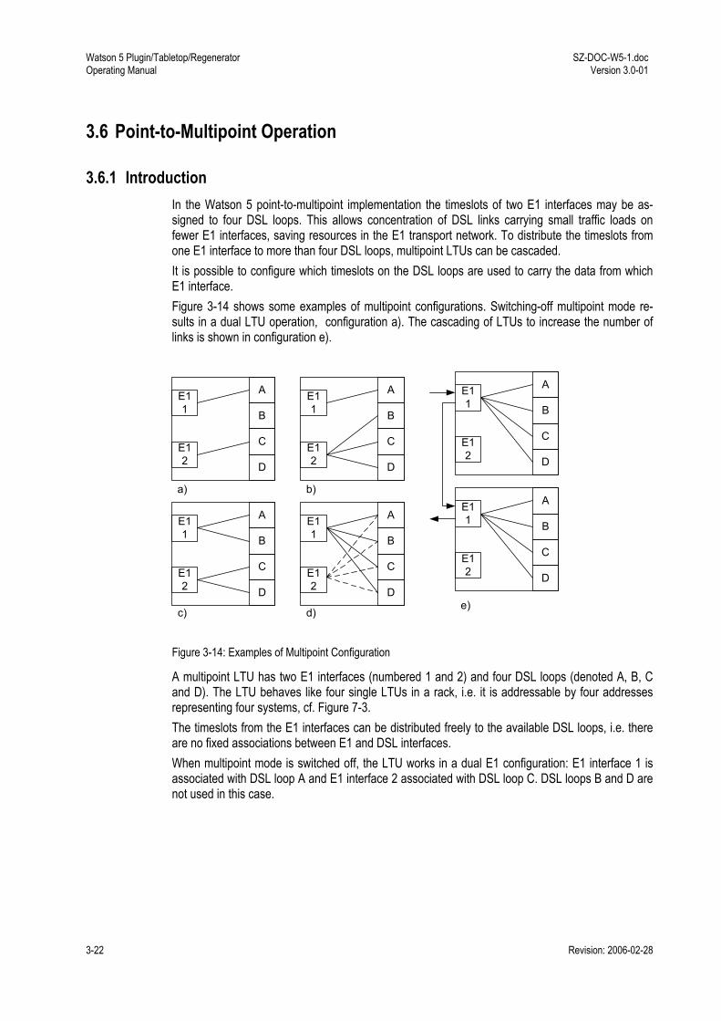
Watson 5 Plugin/Tabletop/Regenerator Operating Manual
SZ-DOC-W5-1.doc Version 3.0-01
3-22 Revision: 2006-02-28
3.6 Point-to-Multipoint Operation
3.6.1 Introduction In the Watson 5 point-to-multipoint implementation the timeslots of two E1 interfaces may be as-signed to four DSL loops. This allows concentration of DSL links carrying small traffic loads on fewer E1 interfaces, saving resources in the E1 transport network. To distribute the timeslots from one E1 interface to more than four DSL loops, multipoint LTUs can be cascaded. It is possible to configure which timeslots on the DSL loops are used to carry the data from which E1 interface. Figure 3-14 shows some examples of multipoint configurations. Switching-off multipoint mode re-sults in a dual LTU operation, configuration a). The cascading of LTUs to increase the number of links is shown in configuration e).
D
A
B
C
E11
E12
D
A
B
C
E11
E12 D
A
B
C
E11
E12
D
A
B
C
E11
E12
D
A
B
C
E11
E12
b)
c) d)e)
D
A
B
C
E11
E12
a)
Figure 3-14: Examples of Multipoint Configuration
A multipoint LTU has two E1 interfaces (numbered 1 and 2) and four DSL loops (denoted A, B, C and D). The LTU behaves like four single LTUs in a rack, i.e. it is addressable by four addresses representing four systems, cf. Figure 7-3. The timeslots from the E1 interfaces can be distributed freely to the available DSL loops, i.e. there are no fixed associations between E1 and DSL interfaces. When multipoint mode is switched off, the LTU works in a dual E1 configuration: E1 interface 1 is associated with DSL loop A and E1 interface 2 associated with DSL loop C. DSL loops B and D are not used in this case.

SZ-DOC-W5-1.doc Version 3.0-01
Watson 5 Plugin/Tabletop/Regenerator Operating Manual
Revision: 2006-02-28 3-23
3.6.2 Configuration The configuration of a point-to-multipoint system includes the following steps: • E1 interface configuration: the E1 interface has to work in framed mode. When CRC4 multi-
frames are used, CRC4 and E-Bit insertion has to be switched on. The E1 interfaces on the NTUs must work in the same configuration as on the LTU.
• DSL interface configuration: the DSL interfaces must be in DSL master mode; the DSL inter-faces at the NTUs are slaves. DSL loops A and B must have the same line rate (configured on loop A), and DSL loops C and D must have the same line rate (configured on loop C). If you have two remote modems which are connected by long loops and two other remote stations short loops then you must use loops A and B (or C and D) for the first two modems and the remaining two loops for the other ones and select two appropriate line rates.
• E1 timeslot mapping: assign timeslots from the E1 interfaces to the DSL loops. Each timeslot of an E1 interface must be mapped to a DSL loop. Note that if no time slots are assigned to E1 port 1 or 2, the corresponding E1 port is switched off (no signal on G.703).
• DSL timeslot mapping: each timeslot of a DSL loop must be mapped to an E1 interface. DSL timeslots are numbered from 0 to 31. These numbers define the E1 timeslot which is carried in that DSL timeslot when using standard time slot mapping according to TS 101 524 for the DSL loops. DSL timeslot n will be always be mapped to E1 timeslot n.

Watson 5 Plugin/Tabletop/Regenerator Operating Manual
SZ-DOC-W5-1.doc Version 3.0-01
3-24 Revision: 2006-02-28
MP
The MP command controls the entire multipoint configuration. It has two parameters: MP cmd map
Cmd Map Description - - Show current multipoint configuration OFF - Switch off multipoint mode, the LTU can then be used as a normal dual LTU
with DSL loops A and C. ON - Switch on multipoint mode, the multipoint configuration used before the last
MP OFF will be restored. 1, 2 0ABCDL E1 timeslot mapping: set mapping of E1 timeslots from E1 interface cmd to
DSL loops. The map is a string of up to 32 characters. The first character determines the target for the first timeslot (TS0), the subsequent characters are assigned to sub-sequent timeslots. 0: TS unused (filled with 11111111) A: TS mapped to DSL loop A B: TS mapped to DSL loop B C: TS mapped to DSL loop C D: TS mapped to DSL loop D L: TS looped back, cf. 8.2.5 If the map contains less than 32 characters, the remaining timeslots are set to 0 (unused)
1, 2 OFF Switches off all timeslots of E1 interface 1 or 2 A,B,C,D 012 DSL timeslot mapping: select which DSL timeslots are used on loop cmd.
The map is a string of up to 32 characters. The first character controls the first timeslot on the DSL loop, the subsequent characters are assigned to subsequent timeslots. 0: TS unused (filled with 11111111) 1, 2: TS filled with TS from E1 interface 1 or 2 respectively
Table 3-8: MP command parameters
After every configuration change, the current multipoint configuration is displayed: ~~~~~~~~~~~~~~~~~~~~~~~~~~~~~~~~~~~~~~~~~~~~~~~~~~~~~~~~~~~~~~~~~~ Multipoint Configuration ~~~~~~~~~~~~~~~~~~~~~~~~~~~~~~~~~~~~~~~~~~~~~~~~~~~~~~~~~~~~~~~~~~ TS 0 0 0 0 0 0 0 0 0 0 1 1 1 1 1 1 1 1 1 1 2 2 2 2 2 2 2 2 2 2 3 3 Nr 0 1 2 3 4 5 6 7 8 9 0 1 2 3 4 5 6 7 8 9 0 1 2 3 4 5 6 7 8 9 0 1 1 - A A A A A A A A A A B B B B B B B B B B C C C C C C D D D D A 2 - - - - - - - - - - - - - - - - - - - - - - - - - - - - - - - - A - 1 1 1 - 1 1 1 1 1 1 1 1 - - - - - - - - - - - - - - - - - - - ->1 1 1 1 1 1 1 1 1 1 1 1 1 1 1 1 1 1 1 1 1 1 1 1 1 1 1 1 1 1 1 1 B - 1 1 1 1 1 1 1 1 1 1 - - - - - - - - - - - - - - - - - - - - - ->1 1 1 1 1 1 1 1 1 1 1 1 1 1 1 1 1 1 1 1 1 1 1 1 1 1 1 1 1 1 1 1 C - - - - - - - - 1 1 1 1 1 1 - - - - - - - - - - - - - - - - - - ->1 1 1 1 1 1 1 1 1 1 1 1 1 1 1 1 1 1 1 1 1 1 1 1 1 1 1 1 1 1 1 1 D - 1 - 1 - 1 - 1 - - - - - - - - - - - - - - - - - - - - - - - - ->1 1 1 1 1 1 1 1 1 1 1 1 1 1 1 1 1 1 1 1 1 1 1 1 1 1 1 1 1 1 1 1 ~~~~~~~~~~~~~~~~~~~~~~~~~~~~~~~~~~~~~~~~~~~~~~~~~~~~~~~~~~~~~~~~~~
The columns show the timeslots (031), the rows the E1 interfaces (1 and 2) and the DSL loops (A, B, C and D).

SZ-DOC-W5-1.doc Version 3.0-01
Watson 5 Plugin/Tabletop/Regenerator Operating Manual
Revision: 2006-02-28 3-25
In the configuration above, the following mapping is displayed: E1 interface 1 TS0 → unused, E1 interface 1 TS1 10, 31 → DSL interface A TS1 3, 5 12, E1 interface 1 TS11 20 → DSL interface B TS1 10, E1 interface 1 TS21 26 → DSL interface C TS8 13, E1 interface 1 TS27 30 → DSL interface D TS1, 3, 5, 7, E1 interface 2 TS0 31 → unused.
The lines marked with -> ( below A, B, C and D) show how the LTU maps the E1 time slots into the transmitted DSL frame. This mapping specifies how the remote NTU will map the extracted DSL time slots into the E1 frame. For example if TS0 on the DSL link contains E1 timeslot 0 with sync pattern (FAS/NFAS) then a 1 will be displayed for TS0 on the line starting with ->. The NTU will map DSL TS0 to E1 TS0, i.e. E1 timeslot 0 is transparently transferred from the E1 interface at the LTU to the E1 interface at the NTU. If TS0 on the DSL link does not contain an E1 timeslot with sync pattern (FAS/NFAS) then a 0 will be displayed for TS0 on the line starting with ->. The remote modem will map DSL TS0 to E1 TS1. E1 TS0 will be filled with FAS/ NFAS information generated in the NTU. The symbol ! at the beginning of a -> line indicates a conflict on the time slot mapping between LTU and NTU. The conflict must be resolved by changing the time slot mapping on the NTU with the MP command. In the following example there is a mapping conflict on the remote modem of DSL loop A: ~~~~~~~~~~~~~~~~~~~~~~~~~~~~~~~~~~~~~~~~~~~~~~~~~~~~~~~~~~~~~~~~~~ Multipoint Configuration ~~~~~~~~~~~~~~~~~~~~~~~~~~~~~~~~~~~~~~~~~~~~~~~~~~~~~~~~~~~~~~~~~~ TS 0 0 0 0 0 0 0 0 0 0 1 1 1 1 1 1 1 1 1 1 2 2 2 2 2 2 2 2 2 2 3 3 Nr 0 1 2 3 4 5 6 7 8 9 0 1 2 3 4 5 6 7 8 9 0 1 2 3 4 5 6 7 8 9 0 1 1 A A A A A A A A A A A B B B B B B B B B B C C C C C C D D D D A 2 - - - - - - - - - - - - - - - - - - - - - - - - - - - - - - - - A 1 1 1 1 1 1 1 1 1 1 1 1 - - - - - - - - - - - - - - - - - - - - !->1 1 1 1 1 1 1 1 1 1 1 1 1 1 1 1 1 1 1 1 1 1 1 1 1 1 1 1 1 1 1 1 B - 1 1 1 1 1 1 1 1 1 1 - - - - - - - - - - - - - - - - - - - - - ->1 1 1 1 1 1 1 1 1 1 1 1 1 1 1 1 1 1 1 1 1 1 1 1 1 1 1 1 1 1 1 1 C - - - - - - - - 1 1 1 1 1 1 - - - - - - - - - - - - - - - - - - ->1 1 1 1 1 1 1 1 1 1 1 1 1 1 1 1 1 1 1 1 1 1 1 1 1 1 1 1 1 1 1 1 D - 1 - 1 - 1 - 1 - - - - - - - - - - - - - - - - - - - - - - - - ->1 1 1 1 1 1 1 1 1 1 1 1 1 1 1 1 1 1 1 1 1 1 1 1 1 1 1 1 1 1 1 1 ~~~~~~~~~~~~~~~~~~~~~~~~~~~~~~~~~~~~~~~~~~~~~~~~~~~~~~~~~~~~~~~~~~
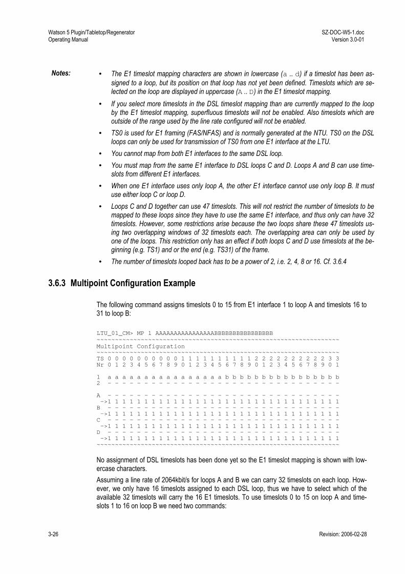
Watson 5 Plugin/Tabletop/Regenerator Operating Manual
SZ-DOC-W5-1.doc Version 3.0-01
3-26 Revision: 2006-02-28
Notes: • The E1 timeslot mapping characters are shown in lowercase (a .. d) if a timeslot has been as-signed to a loop, but its position on that loop has not yet been defined. Timeslots which are se-lected on the loop are displayed in uppercase (A .. D) in the E1 timeslot mapping.
• If you select more timeslots in the DSL timeslot mapping than are currently mapped to the loop by the E1 timeslot mapping, superfluous timeslots will not be enabled. Also timeslots which are outside of the range used by the line rate configured will not be enabled.
• TS0 is used for E1 framing (FAS/NFAS) and is normally generated at the NTU. TS0 on the DSL loops can only be used for transmission of TS0 from one E1 interface at the LTU.
• You cannot map from both E1 interfaces to the same DSL loop. • You must map from the same E1 interface to DSL loops C and D. Loops A and B can use time-
slots from different E1 interfaces. • When one E1 interface uses only loop A, the other E1 interface cannot use only loop B. It must
use either loop C or loop D. • Loops C and D together can use 47 timeslots. This will not restrict the number of timeslots to be
mapped to these loops since they have to use the same E1 interface, and thus only can have 32 timeslots. However, some restrictions arise because the two loops share these 47 timeslots us-ing two overlapping windows of 32 timeslots each. The overlapping area can only be used by one of the loops. This restriction only has an effect if both loops C and D use timeslots at the be-ginning (e.g. TS1) and or the end (e.g. TS31) of the frame.
• The number of timeslots looped back has to be a power of 2, i.e. 2, 4, 8 or 16. Cf. 3.6.4
3.6.3 Multipoint Configuration Example
The following command assigns timeslots 0 to 15 from E1 interface 1 to loop A and timeslots 16 to 31 to loop B: LTU_01_CM> MP 1 AAAAAAAAAAAAAAAABBBBBBBBBBBBBBBB ~~~~~~~~~~~~~~~~~~~~~~~~~~~~~~~~~~~~~~~~~~~~~~~~~~~~~~~~~~~~~~~~~~ Multipoint Configuration ~~~~~~~~~~~~~~~~~~~~~~~~~~~~~~~~~~~~~~~~~~~~~~~~~~~~~~~~~~~~~~~~~~ TS 0 0 0 0 0 0 0 0 0 0 1 1 1 1 1 1 1 1 1 1 2 2 2 2 2 2 2 2 2 2 3 3 Nr 0 1 2 3 4 5 6 7 8 9 0 1 2 3 4 5 6 7 8 9 0 1 2 3 4 5 6 7 8 9 0 1 1 a a a a a a a a a a a a a a a a b b b b b b b b b b b b b b b b 2 - - - - - - - - - - - - - - - - - - - - - - - - - - - - - - - - A - - - - - - - - - - - - - - - - - - - - - - - - - - - - - - - - ->1 1 1 1 1 1 1 1 1 1 1 1 1 1 1 1 1 1 1 1 1 1 1 1 1 1 1 1 1 1 1 1 B - - - - - - - - - - - - - - - - - - - - - - - - - - - - - - - - ->1 1 1 1 1 1 1 1 1 1 1 1 1 1 1 1 1 1 1 1 1 1 1 1 1 1 1 1 1 1 1 1 C - - - - - - - - - - - - - - - - - - - - - - - - - - - - - - - - ->1 1 1 1 1 1 1 1 1 1 1 1 1 1 1 1 1 1 1 1 1 1 1 1 1 1 1 1 1 1 1 1 D - - - - - - - - - - - - - - - - - - - - - - - - - - - - - - - - ->1 1 1 1 1 1 1 1 1 1 1 1 1 1 1 1 1 1 1 1 1 1 1 1 1 1 1 1 1 1 1 1 ~~~~~~~~~~~~~~~~~~~~~~~~~~~~~~~~~~~~~~~~~~~~~~~~~~~~~~~~~~~~~~~~~~
No assignment of DSL timeslots has been done yet so the E1 timeslot mapping is shown with low-ercase characters. Assuming a line rate of 2064kbit/s for loops A and B we can carry 32 timeslots on each loop. How-ever, we only have 16 timeslots assigned to each DSL loop, thus we have to select which of the available 32 timeslots will carry the 16 E1 timeslots. To use timeslots 0 to 15 on loop A and time-slots 1 to 16 on loop B we need two commands:

SZ-DOC-W5-1.doc Version 3.0-01
Watson 5 Plugin/Tabletop/Regenerator Operating Manual
Revision: 2006-02-28 3-27
LTU_01_CM> MP A 11111111111111110000000000000000 ~~~~~~~~~~~~~~~~~~~~~~~~~~~~~~~~~~~~~~~~~~~~~~~~~~~~~~~~~~~~~~~~~~ Multipoint Configuration ~~~~~~~~~~~~~~~~~~~~~~~~~~~~~~~~~~~~~~~~~~~~~~~~~~~~~~~~~~~~~~~~~~ TS 0 0 0 0 0 0 0 0 0 0 1 1 1 1 1 1 1 1 1 1 2 2 2 2 2 2 2 2 2 2 3 3 Nr 0 1 2 3 4 5 6 7 8 9 0 1 2 3 4 5 6 7 8 9 0 1 2 3 4 5 6 7 8 9 0 1 1 A A A A A A A A A A A A A A A A b b b b b b b b b b b b b b b b 2 - - - - - - - - - - - - - - - - - - - - - - - - - - - - - - - - A 1 1 1 1 1 1 1 1 1 1 1 1 1 1 1 1 - - - - - - - - - - - - - - - - ->1 1 1 1 1 1 1 1 1 1 1 1 1 1 1 1 1 1 1 1 1 1 1 1 1 1 1 1 1 1 1 1 B - - - - - - - - - - - - - - - - - - - - - - - - - - - - - - - - ->1 1 1 1 1 1 1 1 1 1 1 1 1 1 1 1 1 1 1 1 1 1 1 1 1 1 1 1 1 1 1 1 C - - - - - - - - - - - - - - - - - - - - - - - - - - - - - - - - ->1 1 1 1 1 1 1 1 1 1 1 1 1 1 1 1 1 1 1 1 1 1 1 1 1 1 1 1 1 1 1 1 D - - - - - - - - - - - - - - - - - - - - - - - - - - - - - - - - ->1 1 1 1 1 1 1 1 1 1 1 1 1 1 1 1 1 1 1 1 1 1 1 1 1 1 1 1 1 1 1 1 ~~~~~~~~~~~~~~~~~~~~~~~~~~~~~~~~~~~~~~~~~~~~~~~~~~~~~~~~~~~~~~~~~~ LTU_01_CM> MP B 01111111111111111000000000000000 ~~~~~~~~~~~~~~~~~~~~~~~~~~~~~~~~~~~~~~~~~~~~~~~~~~~~~~~~~~~~~~~~~~ Multipoint Configuration ~~~~~~~~~~~~~~~~~~~~~~~~~~~~~~~~~~~~~~~~~~~~~~~~~~~~~~~~~~~~~~~~~~ TS 0 0 0 0 0 0 0 0 0 0 1 1 1 1 1 1 1 1 1 1 2 2 2 2 2 2 2 2 2 2 3 3 Nr 0 1 2 3 4 5 6 7 8 9 0 1 2 3 4 5 6 7 8 9 0 1 2 3 4 5 6 7 8 9 0 1 1 A A A A A A A A A A A A A A A A B B B B B B B B B B B B B B B B 2 - - - - - - - - - - - - - - - - - - - - - - - - - - - - - - - - A 1 1 1 1 1 1 1 1 1 1 1 1 1 1 1 1 - - - - - - - - - - - - - - - - ->1 1 1 1 1 1 1 1 1 1 1 1 1 1 1 1 1 1 1 1 1 1 1 1 1 1 1 1 1 1 1 1 B - 1 1 1 1 1 1 1 1 1 1 1 1 1 1 1 1 - - - - - - - - - - - - - - - ->1 1 1 1 1 1 1 1 1 1 1 1 1 1 1 1 1 1 1 1 1 1 1 1 1 1 1 1 1 1 1 1 C - - - - - - - - - - - - - - - - - - - - - - - - - - - - - - - - ->1 1 1 1 1 1 1 1 1 1 1 1 1 1 1 1 1 1 1 1 1 1 1 1 1 1 1 1 1 1 1 1 D - - - - - - - - - - - - - - - - - - - - - - - - - - - - - - - - ->1 1 1 1 1 1 1 1 1 1 1 1 1 1 1 1 1 1 1 1 1 1 1 1 1 1 1 1 1 1 1 1 ~~~~~~~~~~~~~~~~~~~~~~~~~~~~~~~~~~~~~~~~~~~~~~~~~~~~~~~~~~~~~~~~~~
The order of the time slots on the DSL loop is the same as in the E1 frame. In our example time slot 0 from E1 interface 1 is the first time slot assigned to loop A. It will be transmitted on the first time slot in DSL loop A whose character is 1. The second time slot assigned to loop A (E1 time slot 1) will be assigned to the second time slot in DSL loop A whose character is 1, and so on. If the second parameter has less than 32 characters, the remaining time slots are unused, i.e. in-stead of typing MP B 01111111111111111000000000000000 you can use the shortcut MP B 01111111111111111. To switch off all time slots, OFF can be used as the second parameter. Note that in our example TS0 of DSL loop A is used for TS0 from E1 interface 1, whereas TS0 of DSL loop B is not used. This means that the NTU at loop A receives FAS/NFAS information from E1 interface 1 while the NTU at loop B will generate FAS/NFAS locally.
3.6.4 Cascading Multipoint LTUs If only a small number of timeslots has to be sent to every remote station, four DSL loops per E1 in-terface are not enough to fill all 32 timeslots. In such cases, several multipoint LTUs can be cas-caded. The principle used for it is as follows: • The timeslots that are assigned to the four DSL loops of one LTU are mapped as usual • The timeslots that are assigned to DSL loops of other LTUs are looped back, i.e. relayed trans-
parently through the LTU. The E1 transmit signal is connected to the E1 input of the 1st LTU. The E1 output of the 1st LTU will contain the received timeslots assigned to the DSL loops of the 1st LTU plus the looped back time-

Watson 5 Plugin/Tabletop/Regenerator Operating Manual
SZ-DOC-W5-1.doc Version 3.0-01
3-28 Revision: 2006-02-28
slots which are unchanged. This E1 output is connected to the E1 input of the 2nd LTU. The 2nd LTU will send the timeslots that have been looped back in the 1st LTU to its four remote stations. It will loop back the timeslots which have been used by the 1st LTU and also all other timeslots which are used by other LTUs. The E1 output of the 2nd LTU contains the timeslots received from remote sta-tions connected to the 2nd LTU and the looped back timeslots (including the timeslots which have been received by the 1st LTU and have not been changed by the 2nd LTU). This E1 output goes to the E1 input of the next LTU and so on. The E1 output of the last LTU is the common E1 receiving signal. Example: we need to distribute the 32 timeslots of an E1 frame to eight NTUs, with 4 timeslots (256 kbit/s) per NTU. NTUs 1 to 4 (connected to LTU 1) get timeslots 0 3, 4 7, 8 11, 12 15 and NTUs 5 to 8 (connected to LTU 2) get timeslots 16 19, 20 23, 24 27, 28 31:
E1
D
A
B
C
NTU 2
NTU 3
NTU 1
NTU 4
TS 0 .. 3
TS 4 .. 7
TS 8 .. 11
TS 12 .. 15
loop back time slots 16...31
E1
D
A
B
C
NTU 6
NTU 7
NTU 5
NTU 8
TS 16 .. 19
TS 20 .. 23
TS 24 .. 27
TS 28 .. 31
loop back time slots 0...15
LTU 1
LTU 2
Figure 3-15: Cascading of Multipoint LTUs
LTU 1 is configured using the following commands MP 1 AAAABBBBCCCCDDDDLLLLLLLLLLLLLLLL MP A 1111 MP B 01111 MP C 01111 MP D 01111

SZ-DOC-W5-1.doc Version 3.0-01
Watson 5 Plugin/Tabletop/Regenerator Operating Manual
Revision: 2006-02-28 3-29
which results in the following configuration: ~~~~~~~~~~~~~~~~~~~~~~~~~~~~~~~~~~~~~~~~~~~~~~~~~~~~~~~~~~~~~~~~~~ Multipoint Configuration ~~~~~~~~~~~~~~~~~~~~~~~~~~~~~~~~~~~~~~~~~~~~~~~~~~~~~~~~~~~~~~~~~~ TS 0 0 0 0 0 0 0 0 0 0 1 1 1 1 1 1 1 1 1 1 2 2 2 2 2 2 2 2 2 2 3 3 Nr 0 1 2 3 4 5 6 7 8 9 0 1 2 3 4 5 6 7 8 9 0 1 2 3 4 5 6 7 8 9 0 1 1 A A A A B B B B C C C C D D D D L L L L L L L L L L L L L L L L 2 - - - - - - - - - - - - - - - - - - - - - - - - - - - - - - - - A 1 1 1 1 - - - - - - - - - - - - - - - - - - - - - - - - - - - - ->1 1 1 1 1 1 1 1 1 1 1 1 1 1 1 1 1 1 1 1 1 1 1 1 1 1 1 1 1 1 1 1 B - 1 1 1 1 - - - - - - - - - - - - - - - - - - - - - - - - - - - ->1 1 1 1 1 1 1 1 1 1 1 1 1 1 1 1 1 1 1 1 1 1 1 1 1 1 1 1 1 1 1 1 C - 1 1 1 1 - - - - - - - - - - - - - - - - - - - - - - - - - - - ->1 1 1 1 1 1 1 1 1 1 1 1 1 1 1 1 1 1 1 1 1 1 1 1 1 1 1 1 1 1 1 1 D - 1 1 1 1 - - - - - - - - - - - - - - - - - - - - - - - - - - - ->1 1 1 1 1 1 1 1 1 1 1 1 1 1 1 1 1 1 1 1 1 1 1 1 1 1 1 1 1 1 1 1
and LTU 2 as follows: MP 1 LLLLLLLLLLLLLLLLAAAABBBBCCCCDDDD MP A 01111 MP B 01111 MP C 01111 MP D 01111 ~~~~~~~~~~~~~~~~~~~~~~~~~~~~~~~~~~~~~~~~~~~~~~~~~~~~~~~~~~~~~~~~~~ Multipoint Configuration ~~~~~~~~~~~~~~~~~~~~~~~~~~~~~~~~~~~~~~~~~~~~~~~~~~~~~~~~~~~~~~~~~~ TS 0 0 0 0 0 0 0 0 0 0 1 1 1 1 1 1 1 1 1 1 2 2 2 2 2 2 2 2 2 2 3 3 Nr 0 1 2 3 4 5 6 7 8 9 0 1 2 3 4 5 6 7 8 9 0 1 2 3 4 5 6 7 8 9 0 1 1 L L L L L L L L L L L L L L L L A A A A B B B B C C C C D D D D 2 - - - - - - - - - - - - - - - - - - - - - - - - - - - - - - - - A - 1 1 1 1 - - - - - - - - - - - - - - - - - - - - - - - - - - - ->1 1 1 1 1 1 1 1 1 1 1 1 1 1 1 1 1 1 1 1 1 1 1 1 1 1 1 1 1 1 1 1 B - 1 1 1 1 - - - - - - - - - - - - - - - - - - - - - - - - - - - ->1 1 1 1 1 1 1 1 1 1 1 1 1 1 1 1 1 1 1 1 1 1 1 1 1 1 1 1 1 1 1 1 C - 1 1 1 1 - - - - - - - - - - - - - - - - - - - - - - - - - - - ->1 1 1 1 1 1 1 1 1 1 1 1 1 1 1 1 1 1 1 1 1 1 1 1 1 1 1 1 1 1 1 1 D - 1 1 1 1 - - - - - - - - - - - - - - - - - - - - - - - - - - - ->1 1 1 1 1 1 1 1 1 1 1 1 1 1 1 1 1 1 1 1 1 1 1 1 1 1 1 1 1 1 1 1 ~~~~~~~~~~~~~~~~~~~~~~~~~~~~~~~~~~~~~~~~~~~~~~~~~~~~~~~~~~~~~~~~~~
The E1 output of LTU 1 is connected to the E1 input of LTU 2; the E1 equipment at the LTU side is connected to the E1 input of LTU 1 and the E1 output of LTU 2. Note that the number of timeslots which are looped back has to be 2, 4, 8, or 16.

Watson 5 Plugin/Tabletop/Regenerator Operating Manual
SZ-DOC-W5-1.doc Version 3.0-01
3-30 Revision: 2006-02-28
3.7 Performance Monitoring
3.7.1 DSL Parameters The Watson 5 modems provide information about the current Signal Quality and Attenuation of a DSL link: The Signal Quality is the noise margin calculated by the modem:
SQ = SNR1 - SNR0 Where
SQ is the calculated noise margin SNR1 is the signal to noise ratio calculated by the transceiver by analyzing the error correc-
tion bits (Trellis bits) in the line code. SNR0 is the signal to noise ratio that gives a bit error rate of 10-7 in presence of average
white Gassian noise. For TC-PAM16 the theoretical value for SNR0 is 27.7 dB. The Attenuation is the link attenuation calculated by the modem, assuming 0.4mm PE cable without bridged taps and measured at 150 kHz (for linerates of 200 kbit/s up to 1'992 kbit/s) or 200 kHz (for linerates of 2'056 kbit/s and above). Note that the calculated attenuation may differ from the at-tenuation measured by other equipment for other cable configurations (other cable diameter, splices, bridged taps). Both Signal Quality and Attenuation are effective maintenance tools for determining inadequate or bad cable pairs.
3.7.2 G.826 Performance Monitoring The G.826 error performance parameters provide quantitative performance information of a specific loop. They are intended to be used for long-term evaluation of operating DSL links. The evaluation of the G.826 error performance parameters is based on CRC (Cyclic Redundancy Check) error detection. The estimation of a bit-error rate is not within the scope of the G.826 calcu-lations.
DSL Interface On the DSL side, six CRC6 check bits are generated per DSL frame for each channel and direction. The software counts block errors and evaluates the error performance according to ITU-T G.826 using these CRC6 bits.

SZ-DOC-W5-1.doc Version 3.0-01
Watson 5 Plugin/Tabletop/Regenerator Operating Manual
Revision: 2006-02-28 3-31
E1 Interface
SlaveCRC4 CRC6
TX
RX
E1
Gen.
CRC6 DSL
MasterCRC6 CRC4
Test
Gen.
CRC4/E-bit
Test
CRC6
TX
RX
E1
Test
Evaluation G.826
Evaluation G.826
Gen.
Test
CRC4/E-bit
Gen.
Figure 3-16: E1 G.826 Performance Evaluation
On the E1 side, four CRC4 check bits are generated per sub-multiframe (SMF) and compared with the corresponding CRC4 bits in the following SMF. If they do not match, the CRC4 error counter is incremented. The opposite station is informed of detected CRC4 errors by setting E-bits in the transmitted frames. At the same time, the E-bits from the opposite station are counted and can be used for performance monitoring. For the E1 interface, calculations according to G.826 are only possible in framed mode with CRC4 option enabled. In framed mode with CRC4 option disabled only FAS-errors are detected.
ISDN PRA Interface
Slave (NTU-PRA)
CRC4_T CRC4_V3
TX
RX
E1
Gen.
CRC6 DSL
Master (LTU or NTU E1 transparent)
CRC6
Test
Gen.
CRC6
TX
RX
ET
Test
Evaluation G.826
Evaluation G.826
Gen.
Test
CRC4/E-bit
Test
Gen.
CRC4/E-bit
CRC6
Figure 3-17: PRA G.826 Performance Evaluation
When the PRA interface works with CRC4 processing or monitoring (options 2 and 4) four CRC4 check bits are generated per sub-multiframe (SMF) received from the ET and the NT2/TE and are compared with the corresponding CRC4 bits in the following SMF. If they do not match, the corre-sponding CRC4 error counter is incremented. At the same time, the E-bits from the ET and the NT2/TE are counted and can be used for performance monitoring.

Watson 5 Plugin/Tabletop/Regenerator Operating Manual
SZ-DOC-W5-1.doc Version 3.0-01
3-32 Revision: 2006-02-28
3.8 Test loops Test loops can be activated via the monitor from both master and slave sides. Loop 1 will initiate a loopback in the local modem, Loop 2 will initiate a loopback in the remote modems. Regenerators can be individually looped. Only one test loop can be active at a given time. Loops are controlled with the LOOP1, LOOOP2, LOOPREGn monitor commands, cf. 8.2. Activation of a test loop will deactivate any previous loop. A system reset will deactivate any test loop. A non-urgent alarm is raised while any loop is active.
DSL Master Regenerator(s) DSL Slave
UserInterface
UserInterfaceLOOPREGn LOOP2LOOP1
Figure 3-18: Test Loops controlled by the DSL Master
DSL Master Regenerator(s) DSL Slave
UserInterface
UserInterfaceLOOP2 LOOP1
Figure 3-19: Test Loops controlled by the DSL Slave
Notes: • In Firmware Versions before 3.x the DSL slave can only control Loop 1
• Both the Local LED on the slave and the Remote LED on the master is lit amber when a loopback is active.
• On the master side Loop 1 can only be activated locally. Activating Loop 2 turns on Loop 2 at the slave station. The Status Local LED will be lit amber when Loop 1 is active.
• A non-urgent alarm is raised while Loop 1 or Loop 2 is active

SZ-DOC-W5-1.doc Version 3.0-01
Watson 5 Plugin/Tabletop/Regenerator Operating Manual
Revision: 2006-02-28 3-33
3.9 Automatic Protection Switching (APS) Plugin modems with hardware revision B support automatic protection switching. Two DSL links are configured to form a protection group. One link within the group is designated as working link and carries user traffic. The other link is designated the protection link. It synchronizes on DSL level but carries no traffic.
DSL Master
APS
Grou
pE1
E1 (disabled)
DSL Slave
APS
Grou
p
DSL (Working)
DSL (Protection)
E1
E1 (disabled)
DSL Master
APS
Grou
pE1
E1 (disabled)
DSL SlaveAP
S Gr
oup
Working DSL link fails
Protection DSL link carries traffic
E1
E1 (disabled)
Normal Operation
After Automatic Protection Switching Figure 3-20: Automatic Protection Switching
If the working link fails then traffic is switched automatically to the protection link. Protection is bi-directional i. e. transmit and receive directions are switched simultaneously. Protection is non-re-vertive: once a working link has failed and traffic has been switched to the protection link there will be no automatic switch back to the working link should this link become active again. Protection groups can only be enabled/disabled on the Master. After power-up or reset, the protec-tion groups on the Slave are disabled by default, but will be automatically enabled by the Master af-ter link startup. If a protection group is enabled then the line rate of the protection link is automati-cally set equal to the line rate of the working link. On a protection group the user interface of the protection link is switched off. APS is available on single-pair and on two-pair links.
Notes • Hardware revision B and firmware 3.2 or higher is required for APS • APS works only between plugin modems. It is not supported on tabletop modems • Automatic protection switching and ISDN PRA functions are not available at the same time • The protection link cannot carry any traffic while the working link is active.
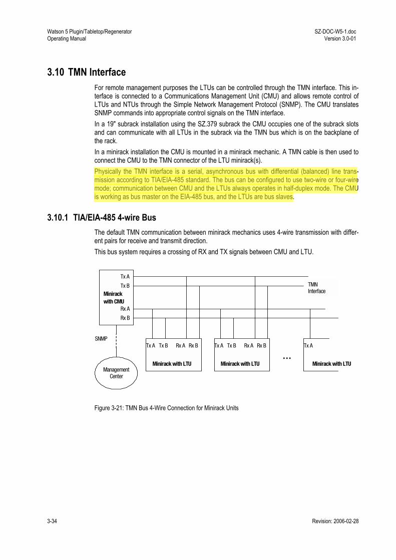
Watson 5 Plugin/Tabletop/Regenerator Operating Manual
SZ-DOC-W5-1.doc Version 3.0-01
3-34 Revision: 2006-02-28
3.10 TMN Interface For remote management purposes the LTUs can be controlled through the TMN interface. This in-terface is connected to a Communications Management Unit (CMU) and allows remote control of LTUs and NTUs through the Simple Network Management Protocol (SNMP). The CMU translates SNMP commands into appropriate control signals on the TMN interface. In a 19" subrack installation using the SZ.379 subrack the CMU occupies one of the subrack slots and can communicate with all LTUs in the subrack via the TMN bus which is on the backplane of the rack. In a minirack installation the CMU is mounted in a minirack mechanic. A TMN cable is then used to connect the CMU to the TMN connector of the LTU minirack(s). Physically the TMN interface is a serial, asynchronous bus with differential (balanced) line trans-mission according to TIA/EIA-485 standard. The bus can be configured to use two-wire or four-wire mode; communication between CMU and the LTUs always operates in half-duplex mode. The CMU is working as bus master on the EIA-485 bus, and the LTUs are bus slaves.
3.10.1 TIA/EIA-485 4-wire Bus The default TMN communication between minirack mechanics uses 4-wire transmission with differ-ent pairs for receive and transmit direction. This bus system requires a crossing of RX and TX signals between CMU and LTU.
Minirackwith CMU
Tx A
Tx B
Rx A
Rx B
Minirack with LTU
Tx A Tx B Rx A Rx B Tx A
… Tx A Tx B Rx A Rx B
SNMP
Management Center
TMN Interface
Minirack with LTU Minirack with LTU
Figure 3-21: TMN Bus 4-Wire Connection for Minirack Units
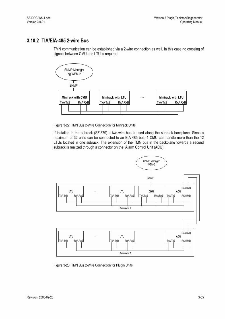
SZ-DOC-W5-1.doc Version 3.0-01
Watson 5 Plugin/Tabletop/Regenerator Operating Manual
Revision: 2006-02-28 3-35
3.10.2 TIA/EIA-485 2-wire Bus TMN communication can be established via a 2-wire connection as well. In this case no crossing of signals between CMU and LTU is required:
SNMP Managereg WEM-2
Minirack with CMUTxA TxB RxARxB
Minirack with LTUTxA TxB RxARxB
Minirack with LTUTxA TxB RxA RxB
...
SNMP
Figure 3-22: TMN Bus 2-Wire Connection for Minirack Units
If installed in the subrack (SZ.379) a two-wire bus is used along the subrack backplane. Since a maximum of 32 units can be connected to an EIA-485 bus, 1 CMU can handle more than the 12 LTUs located in one subrack. The extension of the TMN bus in the backplane towards a second subrack is realized through a connector on the Alarm Control Unit (ACU):
Subrack 2
Subrack 1
SNMP ManagerWEM-2
CMUTxA TxB RxA RxB
LTUTxA TxB RxA RxB
ACUTxA TxB RxA RxB
...
SNMP
LTUTxA TxB RxA RxB
LTUTxA TxB RxA RxB
ACUTxA TxB RxA RxB
... LTUTxA TxB RxA RxB
RxA RxB
RxA RxB
Figure 3-23: TMN Bus 2-Wire Connection for Plugin Units
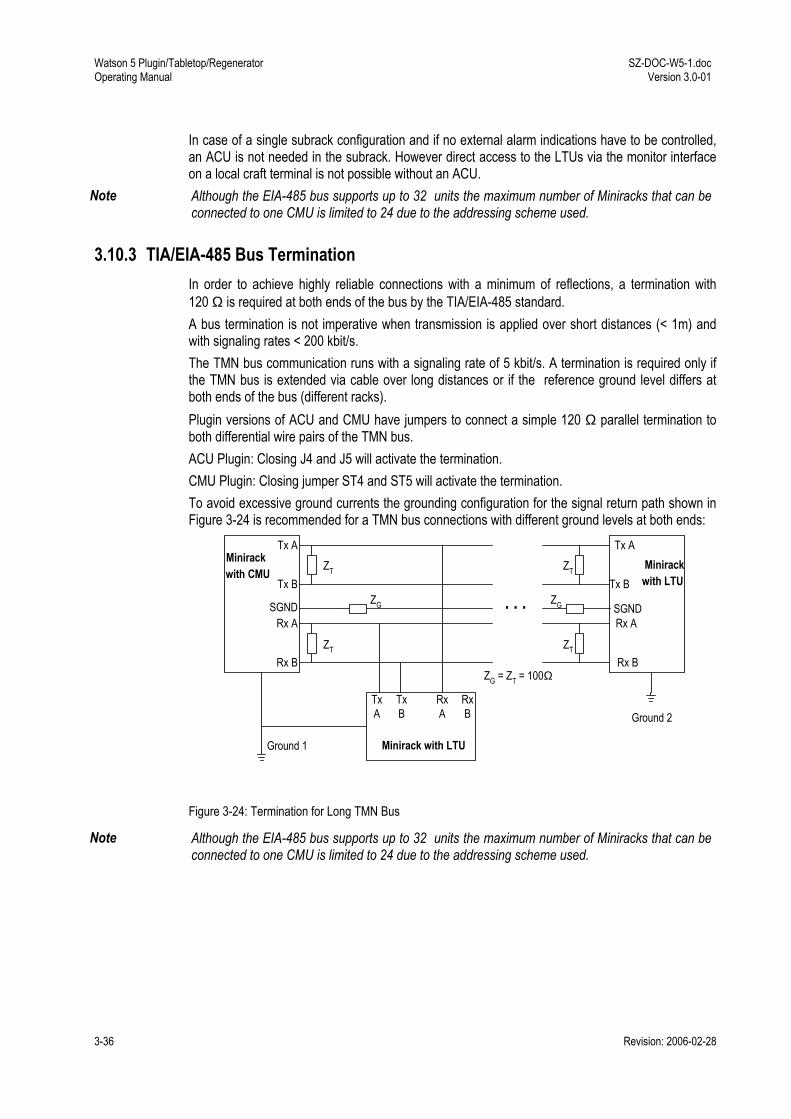
Watson 5 Plugin/Tabletop/Regenerator Operating Manual
SZ-DOC-W5-1.doc Version 3.0-01
3-36 Revision: 2006-02-28
In case of a single subrack configuration and if no external alarm indications have to be controlled, an ACU is not needed in the subrack. However direct access to the LTUs via the monitor interface on a local craft terminal is not possible without an ACU.
Note Although the EIA-485 bus supports up to 32 units the maximum number of Miniracks that can be connected to one CMU is limited to 24 due to the addressing scheme used.
3.10.3 TIA/EIA-485 Bus Termination In order to achieve highly reliable connections with a minimum of reflections, a termination with 120 Ω is required at both ends of the bus by the TIA/EIA-485 standard. A bus termination is not imperative when transmission is applied over short distances (< 1m) and with signaling rates < 200 kbit/s. The TMN bus communication runs with a signaling rate of 5 kbit/s. A termination is required only if the TMN bus is extended via cable over long distances or if the reference ground level differs at both ends of the bus (different racks). Plugin versions of ACU and CMU have jumpers to connect a simple 120 Ω parallel termination to both differential wire pairs of the TMN bus. ACU Plugin: Closing J4 and J5 will activate the termination. CMU Plugin: Closing jumper ST4 and ST5 will activate the termination. To avoid excessive ground currents the grounding configuration for the signal return path shown in Figure 3-24 is recommended for a TMN bus connections with different ground levels at both ends:
Minirackwith CMU
Tx A
Tx B
Rx A
Rx B
Minirack with LTU
TxA
TxB
RxA
RxB
Tx A
Tx B
Rx A
Rx B
SGND
Ground 1
Ground 2
Minirackwith LTU
SGND
ZG = ZT = 100Ω
. . . ZG
ZT
ZT ZT
ZT
ZG
Figure 3-24: Termination for Long TMN Bus
Note Although the EIA-485 bus supports up to 32 units the maximum number of Miniracks that can be connected to one CMU is limited to 24 due to the addressing scheme used.

Revision: 2006-02-28 4-1
4 Watson 5 Regenerator
4.1 Operating modes The Watson 5 regenerator has four DSL interfaces. It can be used either as one regenerator for a two-pair system or as a dual regenerator for two independent 1-pair systems. No configuration is needed to select the operating mode. In fact the only configuration command possible on the re-generator is activation and deactivation of the DSL Autorestart, cf. 8. All other DSL parameters are defined by the DSL master settings.
Note: The additional Z-bit is not supported by the Watson 5 Regenerator. Links with regenerators always have to use 0 Z-bits.
4.2 Interface Designation The regenerator interfaces are named according to the standard [11]: the link towards the LTU is called R-Side (REG-R) because it has the role of a DSL STU-R. The link towards the NTU is called C-Side as it has the role of a DSL STU-C:
LTU Regenerator NTU
C - side(STU-C)
R - side(STU-R
R - Side(REG-R)
C - Side(REG-C)
Loop A
Loop B
Loop A
Loop B
Figure 4-1: Regenerator Interface Designation
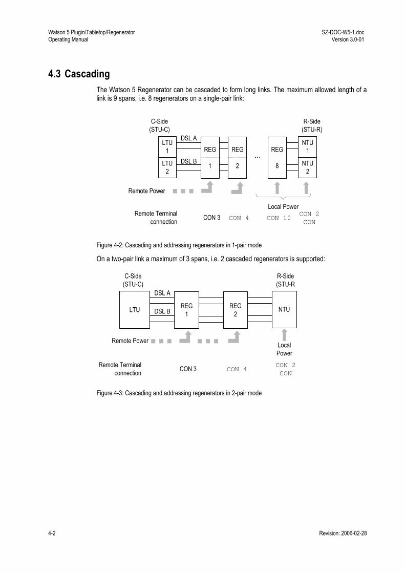
Watson 5 Plugin/Tabletop/Regenerator Operating Manual
SZ-DOC-W5-1.doc Version 3.0-01
4-2 Revision: 2006-02-28
4.3 Cascading The Watson 5 Regenerator can be cascaded to form long links. The maximum allowed length of a link is 9 spans, i.e. 8 regenerators on a single-pair link:
...LTU
1
DSL A
DSL B
C-Side(STU-C)
R-Side(STU-R)
REG
1
Remote Power
Remote Terminalconnection CON 3 CON 4
CON 2CON
LTU2
REG
2
NTU1
NTU2
REG
8
CON 10
Local Power
Figure 4-2: Cascading and addressing regenerators in 1-pair mode
On a two-pair link a maximum of 3 spans, i.e. 2 cascaded regenerators is supported:
LTU
DSL A
DSL B NTU
C-Side(STU-C)
R-Side(STU-R
REG1
REG2
LocalPower
Remote Power
Remote Terminalconnection CON 3 CON 4
CON 2CON
Figure 4-3: Cascading and addressing regenerators in 2-pair mode
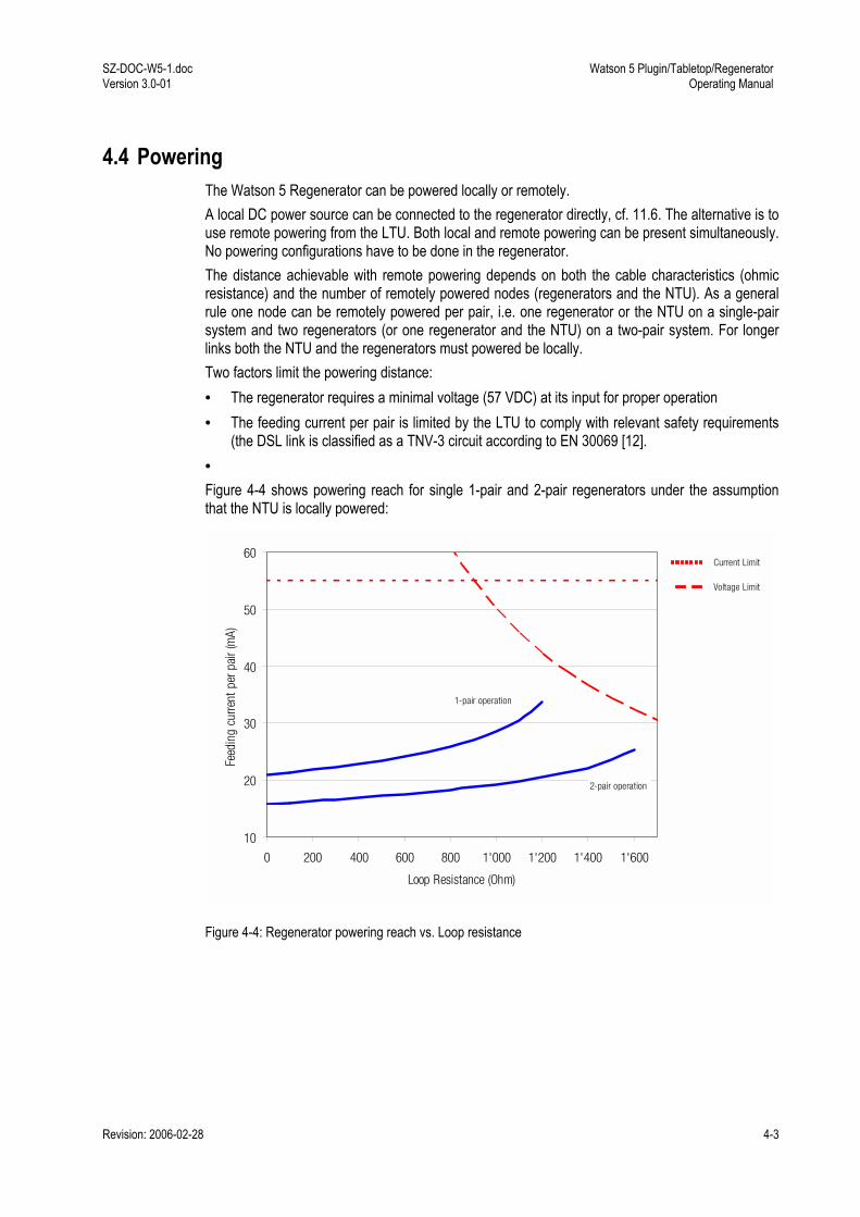
SZ-DOC-W5-1.doc Version 3.0-01
Watson 5 Plugin/Tabletop/Regenerator Operating Manual
Revision: 2006-02-28 4-3
4.4 Powering The Watson 5 Regenerator can be powered locally or remotely. A local DC power source can be connected to the regenerator directly, cf. 11.6. The alternative is to use remote powering from the LTU. Both local and remote powering can be present simultaneously. No powering configurations have to be done in the regenerator. The distance achievable with remote powering depends on both the cable characteristics (ohmic resistance) and the number of remotely powered nodes (regenerators and the NTU). As a general rule one node can be remotely powered per pair, i.e. one regenerator or the NTU on a single-pair system and two regenerators (or one regenerator and the NTU) on a two-pair system. For longer links both the NTU and the regenerators must powered be locally. Two factors limit the powering distance: • The regenerator requires a minimal voltage (57 VDC) at its input for proper operation • The feeding current per pair is limited by the LTU to comply with relevant safety requirements
(the DSL link is classified as a TNV-3 circuit according to EN 30069 [12]. • Figure 4-4 shows powering reach for single 1-pair and 2-pair regenerators under the assumption that the NTU is locally powered:
10
20
30
40
50
60
0 200 400 600 800 1'000 1'200 1'400 1'600
Loop Resistance (Ohm)
Feed
ing
curre
nt p
er p
air (
mA)
2-pair operation
1-pair operation
Current Limit
Voltage Limit
Figure 4-4: Regenerator powering reach vs. Loop resistance

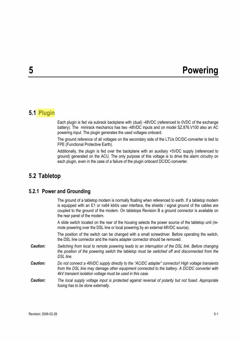
Revision: 2006-02-28 5-1
5 Powering
5.1 Plugin Each plugin is fed via subrack backplane with (dual) -48VDC (referenced to 0VDC of the exchange battery). The minirack mechanics has two -48VDC inputs and on model SZ.876.V100 also an AC powering input. The plugin generates the used voltages onboard. The ground reference of all voltages on the secondary side of the LTUs DC/DC-converter is tied to FPE (Functional Protective Earth). Additionally, the plugin is fed over the backplane with an auxiliary +5VDC supply (referenced to ground) generated on the ACU. The only purpose of this voltage is to drive the alarm circuitry on each plugin, even in the case of a failure of the plugin onboard DC/DC-converter.
5.2 Tabletop
5.2.1 Power and Grounding The ground of a tabletop modem is normally floating when referenced to earth. If a tabletop modem is equipped with an E1 or nx64 kbit/s user interface, the shields / signal ground of the cables are coupled to the ground of the modem. On tabletops Revision B a ground connector is available on the rear panel of the modem. A slide switch located on the rear of the housing selects the power source of the tabletop unit (re-mote powering over the DSL line or local powering by an external 48VDC source). The position of the switch can be changed with a small screwdriver. Before operating the switch, the DSL line connector and the mains adapter connector should be removed.
Caution: Switching from local to remote powering leads to an interruption of the DSL link. Before changing the position of the powering switch the tabletop must be switched off and disconnected from the DSL line.
Caution: Do not connect a 48VDC supply directly to the AC/DC adapter connector! High voltage transients from the DSL line may damage other equipment connected to the battery. A DC/DC converter with 4kV transient isolation voltage must be used in this case.
Caution: The local supply voltage input is protected against reversal of polarity but not fused. Appropriate fusing has to be done externally.
Watson 5 Plugin/Tabletop/Regenerator Operating Manual
SZ-DOC-W5-1.doc Version 3.0-01
5-2 Revision: 2006-02-28
5.2.2 Powering Status Display The current powering status is available in the STATUS display of the monitor (Unit Power Source UPS): UPS = 01 for local powering UPS = 02 for remote powering
Note: UPS display is only available on Revision B/Firmware 3.x modems.
5.2.3 Power Failure Alarm The power supply bit fbit3 of the DSL frame is used to indicate the status of the local power supply in the NTU. The power status bit is set to ONE if power is normal and to ZERO if the power has failed. In case of power loss at the NTU there is enough power left to communicate three "Power Loss" messages towards the LTU. In case of a failure of the NTUs power supply, both LEDs will be extinguished.
5.3 Remote Powering Watson 5 supports the line powering concept of SHDSL. Plugins can supply remote power over the DSL copper pairs. Tabletop modems and Regenerators can be remotely powered over these cop-per pairs. Remote powering is available on all pairs of a multipair system.
5.3.1 Remote power feeding on plugins Plugins are equipped with a remote powering circuits with the following characteristics: • Per pair remote power feed • Cross-wiring tolerant • Power feeding voltage within limits of EN 60950 TNV-3 • Independent current limiters on a per pair basis (microcontroller - controlled) • Tolerant against micro-interruptions • Automatic system restart after power failure On plugins with Hardware Revision A remote powering must be enabled on the plugin by setting the R/L jumpers on the plugin to position "RPWR ON". Note that on modems with several DSL links there is one jumper set per link, labeled "RPWR A", "RPWR B" and on 4-pair modems "RPWR C" and "RPWR D". Once remote powering is enabled through the jumpers the power source can be enabled/disabled per DSL pair using the monitor POWER command, cf. 8.1.3. On plugins with Hardware Revision B there are no remote powering jumpers. Remote powering is directly controlled through the POWER command of the monitor. The remote powering circuit is protected against overvoltage and overcurrent, cf. 12.1.1. In case of overvoltage or overcurrent the powering is disconnected within less than 700ms.
Note: During the power-up phase of the plugin the disconnect delay can be up to 900 ms. When remote powering was disconnected by overcurrent protection then it is switched on automati-cally after 10 seconds. When remote powering was disconnected by overvoltage protection then it will disconnected until a hardware reset is done on the plugin (removal of the plugin from the subrack). In this state the plugin LEDs 1 and 3 will be red blinking and no monitor access is possible. The overvoltage protec-

SZ-DOC-W5-1.doc Version 3.0-01
Watson 5 Plugin/Tabletop/Regenerator Operating Manual
Revision: 2006-02-28 5-3
tion is only activated by serious hardware faults in the feeding circuit which require analysis and re-pair by the manufacturer.
Caution: The plugin should not be connected to the power supply while changing the position of the R/L jumpers.
Note: If a remotely powered tabletop modem consumes more power than can be fed over the DSL link then it will not start up properly. This can lead to the loss of a remote tabletop through misconfigura-tion, e.g. by enabling the nx64 interface on a multiservice tabletop which is operating at the power limit with the nx64 interface switched off. With such reconfigurations the power consumption of the tabletop increases and the modem will not work properly anymore, making it impossible to get back to a working configuration under remote control. In such cases manual intervention at the site of the tabletop is required to reconfigure the unit with a local terminal. The reach attainable with remote powering depends on the power consumption of the and on the loop resistance (wire diameter and cable length and resistance of the feeding/protection circuitry in the plugin).
5.3.2 Remote powering of Tabletops The tabletops have a backplane switch to select local or remote powering. In the default switch po-sition "REM" the tabletop modem is powered via the DSL line and will start operation immediately after connection of the DSL line. In position "LOC", the tabletop modem is powered locally and needs to be connected to a power supply to operate.
5.3.3 Remote powering of plugin NTU On the plugin NTU (SZ.896) a jumper block is used to select local and remote powering. Position the jumper block to X900 for local powering and X901 for remote powering. The jumper block is lo-cated in the upper right corner of the plugin:
Figure 5-1: Remote powering jumpers (plugin NTU)
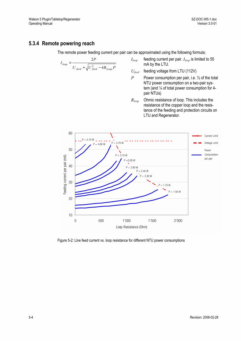
Watson 5 Plugin/Tabletop/Regenerator Operating Manual
SZ-DOC-W5-1.doc Version 3.0-01
5-4 Revision: 2006-02-28
5.3.4 Remote powering reach The remote power feeding current per pair can be approximated using the following formula:
PRUU
PI
Loopfeedfeed
loop4
22 −+
= Iloop feeding current per pair. Iloop is limited to 55
mA by the LTU. Ufeed feeding voltage from LTU (112V) P Power consumption per pair, i.e. ½ of the total
NTU power consumption on a two-pair sys-tem (and ¼ of total power consumption for 4-pair NTUs)
Rloop Ohmic resistance of loop. This includes the resistance of the copper loop and the resis-tance of the feeding and protection circuits on LTU and Regenerator.
10
20
30
40
50
60
0 500 1'000 1'500 2'000
Loop Resistance (Ohm)
Feed
ing
curre
nt p
er p
air (
mA)
P = 1.55 W
P = 1.75 W
P = 2.30 W
P = 2.60 W
P =3.00 W
P = 3.15 W
P = 3.70 WP = 4.80 W
P = 5.10 WCurrent Limit
Voltage Limit
P = 2.45 W
Power
Consumption
per pair
Figure 5-2: Line feed current vs. loop resistance for different NTU power consumptions
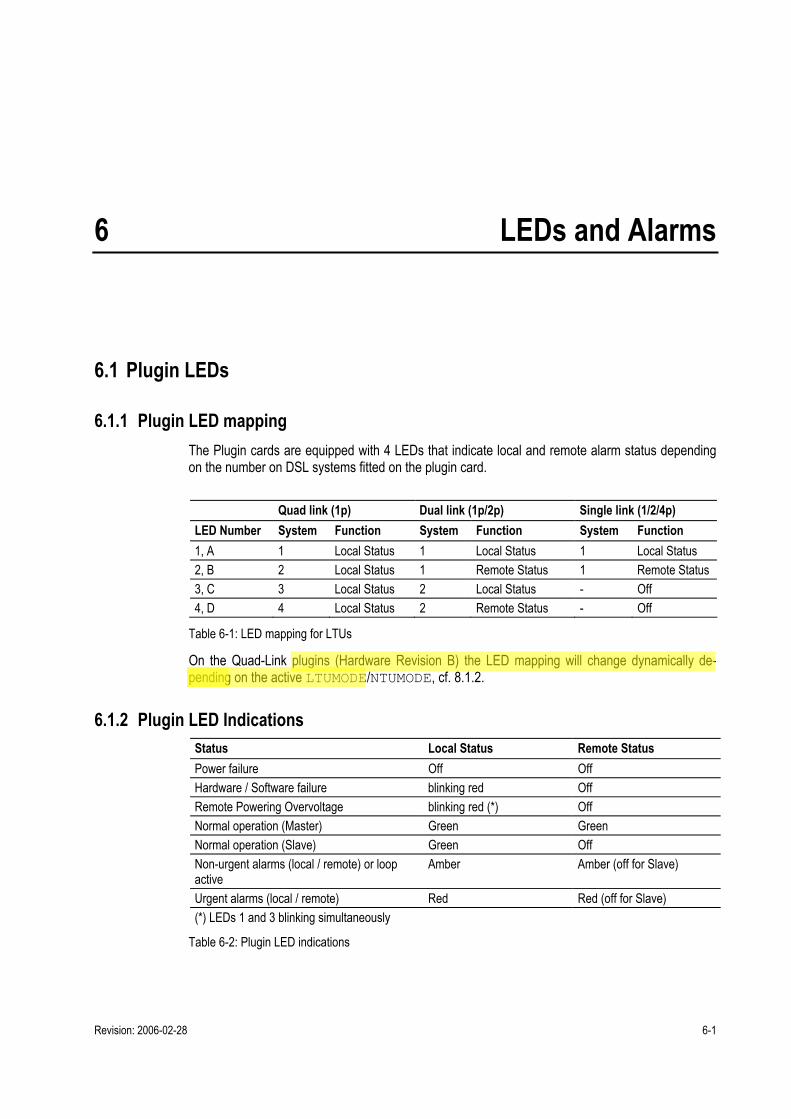
Revision: 2006-02-28 6-1
6 LEDs and Alarms
6.1 Plugin LEDs
6.1.1 Plugin LED mapping The Plugin cards are equipped with 4 LEDs that indicate local and remote alarm status depending on the number on DSL systems fitted on the plugin card. Quad link (1p) Dual link (1p/2p) Single link (1/2/4p) LED Number System Function System Function System Function 1, A 1 Local Status 1 Local Status 1 Local Status 2, B 2 Local Status 1 Remote Status 1 Remote Status 3, C 3 Local Status 2 Local Status - Off 4, D 4 Local Status 2 Remote Status - Off
Table 6-1: LED mapping for LTUs
On the Quad-Link plugins (Hardware Revision B) the LED mapping will change dynamically de-pending on the active LTUMODE/NTUMODE, cf. 8.1.2.
6.1.2 Plugin LED Indications Status Local Status Remote Status Power failure Off Off Hardware / Software failure blinking red Off Remote Powering Overvoltage blinking red (*) Off Normal operation (Master) Green Green Normal operation (Slave) Green Off Non-urgent alarms (local / remote) or loop active
Amber Amber (off for Slave)
Urgent alarms (local / remote) Red Red (off for Slave) (*) LEDs 1 and 3 blinking simultaneously
Table 6-2: Plugin LED indications

Watson 5 Plugin/Tabletop/Regenerator Operating Manual
SZ-DOC-W5-1.doc Version 3.0-01
6-2 Revision: 2006-02-28
During Firmware Download, the LEDs are used as follows:
Download Status Local Status Remote Status Flash erase blinking red Off Download in progress blinking green Off Download completed blinking amber Off Remote download in progress blinking amber blinking amber
Table 6-3: Plugin LED indications during firmware download
6.2 Tabletop LEDs
6.2.1 Tabletop LED mapping The tabletops are fitted with two LEDs labeled "Local" and "Remote". The LEDs display the local status and (if the tabletop is configured as a DSL master) the remote status. On tabletops Revision B and firmware version 3.x LED "Remote" can be configured to display the activity of the user interface (E1 or n x 64), cf. the ACTLED monitor command.
6.2.2 Tabletop LED Indications Status LED "Local" LED "Remote" Power failure Off Off Hardware / Software failure Blinking red Off Normal operation (Master) Green Green Normal operation (Slave) Green Off User Interface Activity on Tx (Slave) Green Blinking Green User Interface Activity on Rx (Slave) Green Blinking Amber Non-urgent alarms (local / remote) or loop active
Amber Amber (off for Slave)
Urgent alarms (local / remote) Red Red (off for Slave)
Table 6-4: Tabletop LED indications
During Firmware download the LEDs are used as follows:
Download Status LED "Local" LED "Remote" Flash erase blinking red Off Download in progress blinking green Off Download completed blinking amber Off Activating remotely downloaded firmware Off blinking amber
Table 6-5: Tabletop LED indications during firmware download

SZ-DOC-W5-1.doc Version 3.0-01
Watson 5 Plugin/Tabletop/Regenerator Operating Manual
Revision: 2006-02-28 6-3
6.3 Alarm Conditions An alarm condition is displayed on the LEDs if one of the following conditions occurs: Urgent alarm (red): • Hardware or software failure (blinking) • Loss of signal / frame alignment on the DSL side (LOSW) • DSL block-error-rate according G.826 ≥ 30% (BER-H) • LTU only: overcurrent detected in remote power feeding circuit (CLD) Non-urgent alarm (amber): • DSL block-error-rate according G.826 > 15% (BER-L) • Either Loop 1, Loop 2, Analog Loopback, or the Regenerator Loopback is active (LOOP1,
LOOP2, ALB, LOOPREG, BERT) • Alarm cut off is activated (ACO) E1 Interface: • Loss of signal or frame alignment on the E1 side (LOS-S, LFA-S) • Loss of external clock (EXT-LOC, in external clock mode only) • Receiving AIS on E1 side (AIS-S) • Excessive block error rate on E1 side (BER-S) PRA Interface: • Loss of signal at the T reference point (LOS-S) • Loss of frame at the T reference point (LFA-S) • Receiving AIS at the T reference point (AIS-S) • Loss of frame at the V3 reference point (LFA-V3) • Receiving AIS at the V3 reference point (AIS-V3) nx64 kbit/s Interface: • Loss of codirectional clock or clock rate mismatch (clock mode: nx64 Port) on the nx64 kbit/s
side (LOC), • Data Terminal Ready (DTR, circuit 108/2) on the nx64 Port is detected as 'OFF'. For X.21, the
control-signal (C) is represented by DTR. • The loops 1 and 2 can be controlled by the circuits 140 (RL) and 141 (LL), thus the alarms
LOOP1 and LOOP2 can also be caused by the nx64 kbit/s interface If no alarm condition is present then the LED will be green. Displaying an urgent alarm has a higher priority than displaying a non-urgent one.

Watson 5 Plugin/Tabletop/Regenerator Operating Manual
SZ-DOC-W5-1.doc Version 3.0-01
6-4 Revision: 2006-02-28
6.4 Alarm Relays
6.4.1 Plugin There are two possibilities for signaling the alarm status of the LTU in the subrack: • The ACU2R gives consolidated alarm signals of all plugin cards of a subrack to the alarm re-
lays Urgent and Non-urgent. • The alarm status is also analyzed by the ACU48R via the internal monitor bus to poll each of
the 24 (=12 dual) LTUs within the subrack and to signal the alarm status to two alarm relays Urgent and Non-urgent specific for each LTU.
Under normal LTU power conditions the two output stages of each LTU are controlled by its micro-controller. In case of a power failure on an LTU, both the Urgent and Non-urgent alarms will be activated on the ACU. (The ACU generates an auxiliary +5 VDC which is used to pull-up the open collector alarm output stages of the LTUs.) Both minirack mechanics and the plugin tabletop housing have urgent and non-urgent alarm relay contacts. Urgent Alarm: • At least one of the LTU LEDs displays an urgent alarm • Power failure of any one of the LTUs • Power failure of the auxiliary +5VDC auxiliary supply on the ACU • Power failure of both 48VDC supplies Non-urgent Alarm: • At least one of the LTU LEDs displays a non-urgent alarm and none of the LTU LEDs dis-
plays an urgent alarm • Power failure of any one of the LTUs • Power failure of the auxiliary +5VDC auxiliary supply on the ACU • Power failure of one of the 48 VDC supplies
6.4.2 Tabletop Two alarm relay contacts Urgent and Non-urgent are located on the monitor connector of the ta-bletop.
Alarm Conditions
Urgent Alarm: • At least one of the tabletop LEDs is red Non-urgent Alarm: • At least one of the tabletop LEDs is amber and none of the tabeltop LEDs is red
Notes: • In case of remote powering the alarm relays are kept inactive to save power
• If alarm cut off is activated (ACO = on), the alarm relays are disabled.

Revision: 2006-02-28 7-1
7 The Monitor
7.1 Introduction For configuration and diagnostics the modems have a serial interface to connect a Terminal or a PC with terminal emulation. The serial interface is available on the tabletop NTUs, the ACU, the minirack mechanics and the plugin tabletop housing. If the LTU/NTU is slave it is also accessible from the master side through the DSL EOC. Only the remote/local powering has to be configured via jumpers on the board of the LTU or via slide switches on the NTU. The monitor terminal or terminal emulation must be VT100 compatible and must be configured as follows: • 9600 baud, asynchronous • 8 bits, no parity, one stop bit • No new line on carriage return (i.e. no line feed on carriage return) • XON/XOFF enabled
Notes: • Between LTU and the terminal the XON/XOFF protocol is used for flow control. In order to re-enable communication with an LTU occasionally left in XOFF state, it is recommended to start each session with Ctrl-Q (=XON) followed by an ECHO command.
• If you use the HyperTerm terminal emulator delivered with Windows® then you must configure HyperTerm for VT100 emulation in the "Settings" tab of the connection properties (File Properties).
7.2 Addressing
7.2.1 Plugin in subrack The monitor terminal connects through the ACU to a serial bus on the subrack backplane which is accessible by all LTUs. At any time, only one of the LTUs in the subrack can be logically connected to the monitor interface. The appropriate LTU interface is addressed (i.e. selected) according to its physical position in the subrack, starting with the leftmost slot number 01 and ascending rightwards to number 12. If an LTU supports a second interface, it may be addressed by adding 12 to the address of the first inter-face. The third interface is addressed by adding 24 to the first address, and the fourth interface by adding 36.

Watson 5 Plugin/Tabletop/Regenerator Operating Manual
SZ-DOC-W5-1.doc Version 3.0-01
7-2 Revision: 2006-02-28
To select the first DSL system on the LTU in slot number nn just type %nn in the terminal, e.g. to select the first DSL link in slot 01, type %01. To select the second system in the same slot number, just type %(nn+12) at the terminal, e.g. the second DSL link in slot 01 is selected with %13.
Subrack
LTU
02
LTU
01
LTU
03
LTU
04
LTU
05
LTU
06
LTU
07
LTU
08
LTU
09
LTU
10
LTU
11
LTU
12
ACU
PSB Unit
First Interface Address
Figure 7-1: Single LTU Interface Addressing Scheme
Subrack
LTU
02
14
LTU
01
13
LTU
03
15
LTU
04
16
LTU
05
17
LTU
06
18
LTU
07
19
LTU
08
20
LTU
09
21
LTU
10
22
LTU
11
23
LTU
12
24
ACU PSB Unit
First Interface Address
Second Interface Address
Figure 7-2: Dual LTU Interface Addressing Scheme
Subrack
LTU
02
14
26
38
LTU
01
13
25
37
LTU
03
15
27
39
LTU
04
16
28
40
LTU
05
17
29
41
LTU
06
18
30
42
LTU
07
19
31
43
LTU
08
20
32
44
LTU
09
21
33
45
LTU
10
22
34
46
LTU
11
23
35
47
LTU
12
24
36
48
ACU
PSB Unit
First Interface
Second Interface
Third Interface
Fourth Interface
Figure 7-3: Quad LTU Interface Addressing Scheme
To see which units in a rack are available, you can use the ECHO command. Each unit will respond with its associated slot number (%SN). The response could be: %01 %03 %08 %10 %11 %12 %15
Note: Each command must be terminated by a carriage return.

SZ-DOC-W5-1.doc Version 3.0-01
Watson 5 Plugin/Tabletop/Regenerator Operating Manual
Revision: 2006-02-28 7-3
7.2.2 Plugin in Minirack mechanics If the plugin is operated in the Minirack mechanics the address number of the DSL interface can be set manually by monitor commands in the Configuration Management (CM) menu. After power-up of a plugin installed in a Minirack the local monitor main menu appears with the first DSL system ac-tivated.
7.2.3 Tabletop There is no addressing procedure required for Tabletop modems. After power-up of a Tabletop modem the local monitor main menu appears with the first DSL system activated.
7.3 Structure and Organization
7.3.1 Menus The structure and organization of the monitor menu is adapted to ITU-T M.3400 for TMN with five sub-sets: Subset Short-form Performance management PM Fault and maintenance management FMM Configuration management CM Security and remote management SM
Table 7-1: Monitor Command Subsets
7.3.2 Welcome Screen After connecting the Terminal/PC the welcome screen is shown with information about the modem type and Firmware Version, e.g.: Watson V SHDSL E1 Monitor V3.1 Quad (4x1p) Copyright (C) 2001-2005 by Schmid Telecom AG Zuerich, Switzerland +------------------------+ | Main Menu | +------------------------+ 1. Performance management (PM) 2. Fault and maintenance management (FMM) 3. Configuration management (CM) 4. Security and remote management (SM) 5. Exit N. Next sub-system LTU_08> Select [1..5,N]:
To select the desired sub-menu, type the appropriate number.

Watson 5 Plugin/Tabletop/Regenerator Operating Manual
SZ-DOC-W5-1.doc Version 3.0-01
7-4 Revision: 2006-02-28
Notes: • The Exit command is only available on the LTU. To address another LTU, type %SN • The 'Next sub-system' command, N, addresses monitoring the next subsystem. It is only avail-
able on the LTUs with more than one system. • You can always use the command H (Help) to display a list of commands available in a par-
ticular menu or submenu.
7.3.3 Shortcuts The available commands depend on the sub-menu currently active. The most popular commands are available in all submenus as shortcuts:
Command Shortcut CONNECT CON
DIAGNOSTIC DIA
DISCONNECT DIS or <ESC> key
Table 7-2: Command Shortcuts
7.3.4 Continuous Displays Some commands (DIAGNOSTIC, G.826, BERT) continuously update the screen with the lat-est information. These commands will stop updating the screen but continue to collect information in the background if a new command is entered that generates displays with more than one line. (e.g. CONFIG, STATUS, ALARM, READBER).

Revision: 2006-02-28 8-1
8 Monitor Command Reference
8.1 Configuration Management CM The commands available in the configuration management menu vary depending on modem hard-ware, firmware and current configuration. Typing H (for Help) gives a list of available commands, e.g. LTU_01_CM> H ~~~~~~~~~~~~~~~~~~~~~~~~~~~~~~~~~~~~~~~~~~~~~~~~~~~~~~~~~~~~~~~~~~ CONFIG Display local configuration G704 [ON,OFF] Set framed mode / transparent mode CRC4 [ON,OFF] Set CRC4 mode on/off EBIT [ON,OFF] Set automatic E-Bit insertion on/off AISGEN [ON,OFF,T] Set AIS generation on/off/transparent AISDET [ON,OFF] Set AIS detection on/off CLK2M [EXT,INT,E1] Select 2Mbit reference clock: external/internal/2Mbit Port MP Display E1 time slot map MP [0..3] Set E1 time slot mapping mode MASTER [ON,OFF] Set SHDSL master mode / slave mode POWER [ON,OFF] Set remote powering on/off RESTART [ON,OFF] Set autorestart on/off BACKOFF [ON,OFF] Set power backoff on/off LINERATE n i a Select line rate (n=[3..36] i=[0,1] a=[0,1]) LTUMODE [1..6,L,N] Select basic LTU operating mode: 1: 4x1p L: Local Oscillator 2: 2x2p (UIF 1&2) N: Network Reference 3: 1x2p + 2x1p 4: 1x4p 5: Multipoint 6: 2x2p (UIF 1&3) GROUP Display available 1+1 protection groups GROUPn [ON,OFF] Enable / disable 1+1 protection group DEFAULT [0..2] Set default configuration MAIN (M) Return to main menu ~~~~~~~~~~~~~~~~~~~~~~~~~~~~~~~~~~~~~~~~~~~~~~~~~~~~~~~~~~~~~~~~~~

Watson 5 Plugin/Tabletop/Regenerator Operating Manual
SZ-DOC-W5-1.doc Version 3.0-01
8-2 Revision: 2006-02-28
8.1.1 General Commands CONFIG
The CONFIG command displays the current configuration of the unit: LTU_01_CM>CONFIG ~~~~~~~~~~~~~~~~~~~~~~~~~~~~~~~~~~~~~~~~~~~~~~~~~~~~~~~~~~~~~~~~~~ Local Configuration Id : 2 Mbit/s G.703 ~~~~~~~~~~~~~~~~~~~~~~~~~~~~~~~~~~~~~~~~~~~~~~~~~~~~~~~~~~~~~~~~~~ 2 Mbit/s Framing : ITU-T G.704 CRC4 : On E-Bit Insertion : On AIS Generation : On AIS Detection : On External Clock : Disabled Data Rate : 01 x 64 = 00064 kbit/s TS Mapping Mode : 2 SHDSL Master/Slave : Master Autorestart : Enabled Power Backoff : Disabled Payload Rate : 00192 kbit/s Operating Mode : 1 Pair Line Rate : 00208 kbit/s Remote Powering : On Regenerators : -- TMN Address : 01 V.11 wires : 02 ~~~~~~~~~~~~~~~~~~~~~~~~~~~~~~~~~~~~~~~~~~~~~~~~~~~~~~~~~~~~~~~~~~
Notes: • After each configuration change, the new configuration is automatically displayed. • If the DSL clock mode is set to "Network reference" (LTUMODE N) then the this is shown in
the Operating Mode line • For NTUs Revision B the wetting current status (wetting current sink on/off) is shown instead
of the Remote Powering status

SZ-DOC-W5-1.doc Version 3.0-01
Watson 5 Plugin/Tabletop/Regenerator Operating Manual
Revision: 2006-02-28 8-3
When both an nx64 kbit/s and an E1 interface are equipped, the configuration display shows first the E1/PRA configuration and then the nx64 kbit/s configuration, e.g. X.21: ~~~~~~~~~~~~~~~~~~~~~~~~~~~~~~~~~~~~~~~~~~~~~~~~~~~~~~~~~~~~~~~~~~ Local Configuration Id : Multiservice ~~~~~~~~~~~~~~~~~~~~~~~~~~~~~~~~~~~~~~~~~~~~~~~~~~~~~~~~~~~~~~~~~~ 2 Mbit/s Framing : ITU-T G.704 CRC4 : Off E-Bit Insertion : -- AIS Generation : On AIS Detection : Off Data Rate : 11 x 64 = 00704 kbit/s X.21 Bitrate : 20 x 64 = 01280 kbit/s Clock Mode : Remote Clock Polarity : Normal Byte Timing : Off Handshake : Disabled SHDSL Master/Slave : Slave Autorestart : Enabled Power Backoff : Disabled Payload Rate : 02048 kbit/s Operating Mode : 1 Pair Line Rate : 02056 kbit/s
DEFAULT
The DEFAULT command sets a default configuration. The following default settings are available: Parameter DEFAULT 0 DEFAULT 1 DEFAULT 2
SHDSL Autorestart Enabled Enabled Enabled Power Backoff Disabled Disabled Disabled Payload Rate 2048 kbit/s 2048 kbit/s 2048 kbit/s Operating Mode 1 Pair 1 Pair 1 Pair Line Rate 02056 kbit/s 02056 kbit/s 02056 kbit/s
2 Mbit/s Framing Transparent ITU-T G.704 Transparent CRC4 -- On -- E-Bit Insertion -- On -- AIS Generation On On On AIS Detection On On Off External Clock -- Disabled -- Data Rate 32 x 64 = 2048 kbit/s 31 x 64 = 1984 kbit/s 32 x 64 = 2048 kbit/s
n x 64 Bitrate (*) 32 x 64 = 2048 kbit/s 32 x 64 = 2048 kbit/s 32 x 64 = 2048 kbit/s Clock Mode Remote Internal Remote Clock Direction Codirectional Codirectional Codirectional V.54 Loops Disabled Disabled Disabled Handshake Disabled Disabled Disabled
(*) for multiservice modems the data interface will be set to V.35 with bitrate 0 (n x 64 interface off)
Table 8-1: DEFAULT values

Watson 5 Plugin/Tabletop/Regenerator Operating Manual
SZ-DOC-W5-1.doc Version 3.0-01
8-4 Revision: 2006-02-28
For the Watson 5 plugins with 4 x E1 user interfaces (SZ.866.V614, SZ.866.V634) the DEFAULT values are as follows: Parameter DEFAULT 0 DEFAULT 1 DEFAULT 2
SHDSL Autorestart Enabled Enabled Enabled Power Backoff Disabled Disabled Disabled Payload Rate 2048 kbit/s 2048 kbit/s 2048 kbit/s Operating Mode (*) 1/2/4 Pair 1/2/4 Pair 1/2/4 Pairs Linerate per pair (*) 2056/1032/520 kbit/s 2056/1032/520 kbit/s 2056/1032/520 kbit/s
2 Mbit/s Framing Transparent ITU-T G.704 Transparent CRC4 -- On -- E-Bit Insertion -- On -- AIS Generation On On On AIS Detection On On Off External Clock -- Disabled -- Data Rate 32 x 64 = 2048 kbit/s 31 x 64 = 1984 kbit/s 32 x 64 = 2048 kbit/s Linerate per pair (*) 2056/1032/520 kbit/s 2056/1032/520 kbit/s 2056/1032/520 kbit/s
(*) operating mode and linerate depend on the current LTUMODE. Each system on the card will be config-ured to carry 2048 kbit/s Payload rate, e.g. a single-pair system for 2056 kbit/s and a two-pair system for 2 x 1032 kbit/s.
Table 8-2: DEFAULT values for Watson 5 plugins with 4 x E1 user interfaces
Notes • The default configurations in Table 8-1 are given for DSL master mode. If the modem is in DSL slave mode then the DSL linerate is determined by the DSL master and not by the DEFAULT command.
• The factory setting can be loaded using the DEFAULT 2 command. All DSL LTUs and NTUs are delivered with this configuration (LTUs as DSL master, NTUs as DSL slave).
• The Master/Slave and Remote Powering settings are not affected by the DEFAULT command

SZ-DOC-W5-1.doc Version 3.0-01
Watson 5 Plugin/Tabletop/Regenerator Operating Manual
Revision: 2006-02-28 8-5
8.1.2 Card Configuration LTUMODE
LTU plugins with Hardware Revision B and Firmware Version 3.x can be configured flexibly to sup-port 1/2/4 pair operation and different DSL clocking modes. This is done with the LTUMODE command. Entering LTUMODE without any parameter will display the current LTU basic mode and mapping of E1 user interfaces to xDSL interfaces: LTU_01_CM> LTUMODE ~~~~~~~~~~~~~~~~~~~~~~~~~~~~~~~~~~~~~~~~~~~~~~~~~~~~~~~~~~~~~~~~~~ LTUMODE 2: 2x2p, UIF 1 + 2 ~~~~~~~~~~~~~~~~~~~~~~~~~~~~~~~~~~~~~~~~~~~~~~~~~~~~~~~~~~~~~~~~~~ System Clk E1 Port SHDSL Port Line Rate Power ~~~~~~~~~~~~~~~~~~~~~~~~~~~~~~~~~~~~~~~~~~~~~~~~~~~~~~~~~~~~~~~~~~ LTU_01: E1 Rx 1 <------+------> 1 1032 On | +------> 2 1032 On LTU_13: E1 Rx 2 <------+------> 3 1032 On | +------> 4 1032 On ~~~~~~~~~~~~~~~~~~~~~~~~~~~~~~~~~~~~~~~~~~~~~~~~~~~~~~~~~~~~~~~~~~ LTU_01_CM>
In the example above the plugin is configured as two 2-pair systems. The first system uses DSL ports 1/2 and E1 port 1. The second system uses DSL ports 3/4 and E1 port 2. The first system is addressed with %01, the second system with %13. Note that the addresses %25 and %37 do not exist in this configuration (they would be available if the card would be configured as 4 independent 1-pair systems).
Note The display of the LTUMODE also reflects the currently active MODE in multipair operation, cf. 8.1.3 Available LTU Modes: 1 4x1p, four independent 1-pair systems 2 2x2p, two independent 2-pair systems connected to E1 user interfaces 1 + 2 3 1x2p + 2x1p, one 2-pair and two 1-pair systems (E1 user interfaces 1, 2 and 4) 4 1x4p, one 4-pair system connected to E1 user interface 1 5 Multipoint 6 2x2p, two independent 2-pair systems connected to E1 user interfaces 1 + 3 10(*) 2x1p, two independent 1-pair systems connected to E1 user interfaces 1+2 L Selects DSL Clock Mode 1 (Local Clock). Cf. 3.1.4 N Selects DSL Clock Mode 2 (Network Reference). Cf. 3.1.4
(*) Only available on SZ.866.V512 and SZ.866.V532
Table 8-3 : LTU Modes
When changing the LTU operating mode, all DSL links will be reset and the current configuration will be overwritten with the default configuration of the new mode as per Table 8-2. Note that only the DSL defaults as per Table 8-2 are set, the E1 interface configuration is not changed by LTUMODE. For security reasons, the command must be confirmed. The LTUMODE can only be changed within the configuration menu of the first system. LTU sys-tems (user interfaces respectively DSL interfaces) coupled or deactivated by the basic operating mode can neither be accessed by TMN commands nor by monitor commands and will not respond to the ECHO command.

Watson 5 Plugin/Tabletop/Regenerator Operating Manual
SZ-DOC-W5-1.doc Version 3.0-01
8-6 Revision: 2006-02-28
NTUMODE
NTU plugins can be configured flexibly to support 1/2/4 pair operation. This is done with the NTUMODE command. Entering NTUMODE without any parameter will display the current NTU basic mode and mapping of E1 user interfaces to xDSL interfaces: NTU_04_CM> NTUMODE ~~~~~~~~~~~~~~~~~~~~~~~~~~~~~~~~~~~~~~~~~~~~~~~~~~~~~~~~~~~~~~~~~~ NTUMODE 3: 1x2p + 2x1p ~~~~~~~~~~~~~~~~~~~~~~~~~~~~~~~~~~~~~~~~~~~~~~~~~~~~~~~~~~~~~~~~~~ System Clk E1 Port SHDSL Port Line Rate Wetting ~~~~~~~~~~~~~~~~~~~~~~~~~~~~~~~~~~~~~~~~~~~~~~~~~~~~~~~~~~~~~~~~~~ NTU_04: E1 Rx 1 <-------------> 1 2320 Off NTU_16: E1 Rx 2 <-------------> 2 2056 Off NTU_28: E1 Rx 3 <------+------> 3 1032 Off | +------> 4 1032 Off ~~~~~~~~~~~~~~~~~~~~~~~~~~~~~~~~~~~~~~~~~~~~~~~~~~~~~~~~~~~~~~~~~~ NTU_04_CM>
In the example above the plugin is configured as two 1-pair systems and one 2-pair system. The first system uses DSL port 1 and E1 port 1, the second system uses DSL port 2 and E1 port 2, and the third system uses DSL ports 3/4 and E1 port 3. Wetting current is disabled on all systems. The first system is addressed with %04, the second system with %16, the third with %28. Note that the addresses %40 does not exist in this configuration.
Note The display of the NTUMODE also reflects the currently active MODE in multipair operation, cf. 8.1.3 Available NTU Modes: 1 4x1p, four independent 1-pair systems 2 2x2p, two independent 1-pair systems connected to E1 user interfaces 1 + 2 3 1x2p + 2x1p, one 2-pair and two 1-pair systems (E1 user interfaces 1, 2 and 4) 4 1x4p, one 4-pair system connected to E1 user interface 1 6 2x2p, two independent 2-pair systems connected to E1 user interfaces 1 + 3
Table 8-4 : NTU Modes
When changing the NTU operating mode, all DSL links will be reset and the current configuration will be overwritten with the default configuration of the new mode as per Table 8-2. Note that only the DSL defaults as per Table 8-2 are set, the E1 interface configuration is not changed by NTUMODE. For security reasons, the command must be confirmed. The NTUMODE and the WETTING current settings can only be changed within the configuration menu of the first system. NTU systems (user interfaces respectively DSL interfaces) coupled or de-activated by the basic operating mode can neither be accessed by TMN commands nor by monitor commands and will not respond to the ECHO command.

SZ-DOC-W5-1.doc Version 3.0-01
Watson 5 Plugin/Tabletop/Regenerator Operating Manual
Revision: 2006-02-28 8-7
8.1.3 DSL Configuration The following configuration commands relate to the configuration of the DSL link:
BACKOFF
Set SHDSL Power Back-Off function ON / OFF.
LINERATE
Set line rate: LINERATE n i a
Parameters: n denotes the number of DSL timeslots to be transmitted (3 ≤ n ≤ 36) i 1 denotes the Z-bits automatically used to increase the EOC bandwidth of about 3.2
kbit/s by 8 kbit/s (i = 0 or 1, default i =1 ) a 1 denotes asymmetric PSD operation.
Notes • Asymmetric PSD is only possible without Z-bits, i.e. a = 1 implies i = 0 • The additional Z-bit is not supported by the Watson 5 Regenerator. Links with regenerators al-
ways have to use 0 Z-bits, i.e. i must be 0
MASTER
Set DSL master mode ON / OFF (MASTER OFF configures the modem as DSL slave). Configuration as DSL slave is only possible if the R/L jumper on the LTU is set in RPWR OFF posi-tion, cf. 5.3. On a dual-link LTU it is possible to configure one link as DSL master and the other link as DSL slave.
MODE
Select DSL operating mode: MODE 1: 1 pair operation MODE 2: 2 pair operation MODE 3: 3 pair operation MODE 4: 4 pair operation Cf. 3.1.3 for details on multipair operation.

Watson 5 Plugin/Tabletop/Regenerator Operating Manual
SZ-DOC-W5-1.doc Version 3.0-01
8-8 Revision: 2006-02-28
On Hardware revision B the LTUMODE and NTUMODE displays reflect the currently selected MODE, e.g. for a plugin configured with NTUMODE 4 (single link with 4 DSL pairs) and MODE 2 (2-pair operation): NTU_05_CM> NTUMODE ~~~~~~~~~~~~~~~~~~~~~~~~~~~~~~~~~~~~~~~~~~~~~~~~~~~~~~~~~~~~~~~~~~ NTU Mode 4: 1x4p ~~~~~~~~~~~~~~~~~~~~~~~~~~~~~~~~~~~~~~~~~~~~~~~~~~~~~~~~~~~~~~~~~~ System Clk E1 Port SHDSL Port Line Rate Wetting ~~~~~~~~~~~~~~~~~~~~~~~~~~~~~~~~~~~~~~~~~~~~~~~~~~~~~~~~~~~~~~~~~~ NTU_05: E1 Rx 1 <------+------> 1 -- Off | +------> 2 -- Off x +------> 3 -- Off x +------> 4 -- Off ~~~~~~~~~~~~~~~~~~~~~~~~~~~~~~~~~~~~~~~~~~~~~~~~~~~~~~~~~~~~~~~~~~
POWER
Set remote powering ON / OFF. Note: The POWER command is not available in Revision A plugins if the R/L jumper on the plugin is not
set to RPWR ON, cf. 5.3) Warning: If a multiservice NTU is remotely powered be sure not to enable the nx64 kbit/s interface if the mo-
dem is operating at the remote power limit with just the E1 interface enabled. Due to the higher power consumption of the nx64 kbit/s interface at the NTU side the current limiter at the LTU will possibly operate, thus switching off remote power feeding. Subsequent startups will not be success-ful. The system will not operate until it is reconfigured locally at the NTU site.
RESTART
Set Autorestart ON / OFF.
WETTING
Enables (ON) or disables (OFF) sinking of wetting current. Only available on plugin NTU cards and tabletops Revision B. On plugin cards wetting current is enabled and disabled globally for all DSL pairs of the card. Configuration is done in the first DSL system of the card. If remote powering is enabled then WETTING is automatically set to OFF.
8.1.4 User Interface Configuration ACTLED
Turns user interface activity on (ACTLED ON) or off (ACTLED OFF). If turned on then activity on the user interface will be shown on the LED "2" (LED "Remote") on the tabletop modem. The Ac-tivity LED blinks if at least one signal transition has been detected within one second on Tx or Rx. If activity is detected on Tx (user data towards DSL) then the LED is blinking green. If activity is de-tected on Rx (user data from DSL) the LED will blink amber. If activity is detected on both Tx Data and Rx Data, the LED will blink alternating green/amber. User interface activity indication is available on modems with a nx64 user interface and on modems with an E1 user interface and if the interface is operated in G.703 transparent/unframed mode. In case of multiservice operation, only activity of the nx64 user interface is indicated, while activity on the E1 interface is not monitored.

SZ-DOC-W5-1.doc Version 3.0-01
Watson 5 Plugin/Tabletop/Regenerator Operating Manual
Revision: 2006-02-28 8-9
Invoking a DEFAULT command will disable user interface activity indication. Notes: • User interface activity indication is only available if the unit is configured as Slave.
• ACTLED is available with Firmware release 3.x
MP
The MP command without parameters displays the E1 timeslot mapping mode. LTU_01_CM> MP 1 ~~~~~~~~~~~~~~~~~~~~~~~~~~~~~~~~~~~~~~~~~~~~~~~~~~~~~~~~~~~~~~~~~~ E1 Timeslot Map (Mode: 1) ~~~~~~~~~~~~~~~~~~~~~~~~~~~~~~~~~~~~~~~~~~~~~~~~~~~~~~~~~~~~~~~~~~ TS 0 0 0 0 0 0 0 0 0 0 1 1 1 1 1 1 1 1 1 1 2 2 2 2 2 2 2 2 2 2 3 3 Nr 0 1 2 3 4 5 6 7 8 9 0 1 2 3 4 5 6 7 8 9 0 1 2 3 4 5 6 7 8 9 0 1 Tx 1 1 1 1 1 1 1 1 1 1 1 1 1 1 1 1 1 1 1 1 1 1 1 1 1 1 1 1 1 1 1 1 Rx 1 1 1 1 1 1 1 1 1 1 1 1 1 1 1 1 1 1 1 1 1 1 1 1 1 1 1 1 1 1 1 1 ~~~~~~~~~~~~~~~~~~~~~~~~~~~~~~~~~~~~~~~~~~~~~~~~~~~~~~~~~~~~~~~~~~
Attributes: TS Nr Timeslot number (0 .. 31) Tx: 0 timeslot is not mapped to DSL 1 timeslot is mapped to DSL N timeslot is mapped to DSL and contains nx64 data (nx64 - E1 applications) - E1 Port switched off (Multiservice only) Rx: 0 timeslot is filled with all ones (except TS0) 1 timeslot is mapped from DSL N timeslot is mapped from DSL and contains nx64 data (nx64 - E1 applications) - DSL disconnected or E1 Port switched off (Multiservice only)
Note: Tx mapping is given by the local configuration, Rx mapping by the mapping mode configured on the remote site. Theoretically it is possible to use different mapping modes in each direction. However, if Tx and Rx mapping are not equal, a warning message is displayed.
Examples:
Line rate 3, 1 Pair, Mapping Mode 0 (frE1 - frE1): ~~~~~~~~~~~~~~~~~~~~~~~~~~~~~~~~~~~~~~~~~~~~~~~~~~~~~~~~~~~~~~~~~~ E1 Timeslot Map (Mode: 0) ~~~~~~~~~~~~~~~~~~~~~~~~~~~~~~~~~~~~~~~~~~~~~~~~~~~~~~~~~~~~~~~~~~ TS 0 0 0 0 0 0 0 0 0 0 1 1 1 1 1 1 1 1 1 1 2 2 2 2 2 2 2 2 2 2 3 3 Nr 0 1 2 3 4 5 6 7 8 9 0 1 2 3 4 5 6 7 8 9 0 1 2 3 4 5 6 7 8 9 0 1 Tx 0 1 1 1 0 0 0 0 0 0 0 0 0 0 0 0 0 0 0 0 0 0 0 0 0 0 0 0 0 0 0 0 Rx 0 1 1 1 0 0 0 0 0 0 0 0 0 0 0 0 0 0 0 0 0 0 0 0 0 0 0 0 0 0 0 0 ~~~~~~~~~~~~~~~~~~~~~~~~~~~~~~~~~~~~~~~~~~~~~~~~~~~~~~~~~~~~~~~~~~

Watson 5 Plugin/Tabletop/Regenerator Operating Manual
SZ-DOC-W5-1.doc Version 3.0-01
8-10 Revision: 2006-02-28
Line rate 3, 1 Pair, Mapping Mode 1 (frE1 - frE1): ~~~~~~~~~~~~~~~~~~~~~~~~~~~~~~~~~~~~~~~~~~~~~~~~~~~~~~~~~~~~~~~~~~ E1 Timeslot Map (Mode: 1) ~~~~~~~~~~~~~~~~~~~~~~~~~~~~~~~~~~~~~~~~~~~~~~~~~~~~~~~~~~~~~~~~~~ TS 0 0 0 0 0 0 0 0 0 0 1 1 1 1 1 1 1 1 1 1 2 2 2 2 2 2 2 2 2 2 3 3 Nr 0 1 2 3 4 5 6 7 8 9 0 1 2 3 4 5 6 7 8 9 0 1 2 3 4 5 6 7 8 9 0 1 Tx 1 1 1 0 0 0 0 0 0 0 0 0 0 0 0 0 0 0 0 0 0 0 0 0 0 0 0 0 0 0 0 0 Rx 1 1 1 0 0 0 0 0 0 0 0 0 0 0 0 0 0 0 0 0 0 0 0 0 0 0 0 0 0 0 0 0 ~~~~~~~~~~~~~~~~~~~~~~~~~~~~~~~~~~~~~~~~~~~~~~~~~~~~~~~~~~~~~~~~~~
Line rate 3, 1 Pair, Mapping Mode 2 (frE1 - frE1): ~~~~~~~~~~~~~~~~~~~~~~~~~~~~~~~~~~~~~~~~~~~~~~~~~~~~~~~~~~~~~~~~~~ E1 Timeslot Map (Mode: 2) ~~~~~~~~~~~~~~~~~~~~~~~~~~~~~~~~~~~~~~~~~~~~~~~~~~~~~~~~~~~~~~~~~~ TS 0 0 0 0 0 0 0 0 0 0 1 1 1 1 1 1 1 1 1 1 2 2 2 2 2 2 2 2 2 2 3 3 Nr 0 1 2 3 4 5 6 7 8 9 0 1 2 3 4 5 6 7 8 9 0 1 2 3 4 5 6 7 8 9 0 1 Tx 0 1 1 0 0 0 0 0 0 0 0 0 0 0 0 0 1 0 0 0 0 0 0 0 0 0 0 0 0 0 0 0 Rx 0 1 1 0 0 0 0 0 0 0 0 0 0 0 0 0 1 0 0 0 0 0 0 0 0 0 0 0 0 0 0 0 ~~~~~~~~~~~~~~~~~~~~~~~~~~~~~~~~~~~~~~~~~~~~~~~~~~~~~~~~~~~~~~~~~~
Line rate 3, 1 Pair, Mapping Mode 3 (frE1 - frE1): ~~~~~~~~~~~~~~~~~~~~~~~~~~~~~~~~~~~~~~~~~~~~~~~~~~~~~~~~~~~~~~~~~~ E1 Timeslot Map (Mode: 3) ~~~~~~~~~~~~~~~~~~~~~~~~~~~~~~~~~~~~~~~~~~~~~~~~~~~~~~~~~~~~~~~~~~ TS 0 0 0 0 0 0 0 0 0 0 1 1 1 1 1 1 1 1 1 1 2 2 2 2 2 2 2 2 2 2 3 3 Nr 0 1 2 3 4 5 6 7 8 9 0 1 2 3 4 5 6 7 8 9 0 1 2 3 4 5 6 7 8 9 0 1 Tx 1 1 0 0 0 0 0 0 0 0 0 0 0 0 0 0 1 0 0 0 0 0 0 0 0 0 0 0 0 0 0 0 Rx 1 1 0 0 0 0 0 0 0 0 0 0 0 0 0 0 1 0 0 0 0 0 0 0 0 0 0 0 0 0 0 0 ~~~~~~~~~~~~~~~~~~~~~~~~~~~~~~~~~~~~~~~~~~~~~~~~~~~~~~~~~~~~~~~~~~
Line rate 3, 1 Pair, Mapping Mode 0, (frE1 nx64): ~~~~~~~~~~~~~~~~~~~~~~~~~~~~~~~~~~~~~~~~~~~~~~~~~~~~~~~~~~~~~~~~~~ E1 Timeslot Map (Mode: 0) ~~~~~~~~~~~~~~~~~~~~~~~~~~~~~~~~~~~~~~~~~~~~~~~~~~~~~~~~~~~~~~~~~~ TS 0 0 0 0 0 0 0 0 0 0 1 1 1 1 1 1 1 1 1 1 2 2 2 2 2 2 2 2 2 2 3 3 Nr 0 1 2 3 4 5 6 7 8 9 0 1 2 3 4 5 6 7 8 9 0 1 2 3 4 5 6 7 8 9 0 1 Tx 0 N N N 0 0 0 0 0 0 0 0 0 0 0 0 0 0 0 0 0 0 0 0 0 0 0 0 0 0 0 0 Rx 0 N N N 0 0 0 0 0 0 0 0 0 0 0 0 0 0 0 0 0 0 0 0 0 0 0 0 0 0 0 0
The MP command with a parameter sets E1 mapping mode (cf. 3.5) MP 0 : TS0 not transmitted, TS16 only if frE1 > 16 MP 1 : TS0 always transmitted, TS16 only if frE1 > 16 MP 2 : TS0 not transmitted, TS16 always transmitted MP 3 : TS0 and TS16 always transmitted Multiservice only: MP ON: switch E1 Port on MP OFF: switch E1 Port off
Note: In Multipoint operation the MP command has other parameters, cf. chapter 3.6.

SZ-DOC-W5-1.doc Version 3.0-01
Watson 5 Plugin/Tabletop/Regenerator Operating Manual
Revision: 2006-02-28 8-11
UIF Set the user interface type E1 E1 user interface PRA E1 user interface with PRA functions V35 nx64 interface with V.35 V36 nx64 interface with V.36 X21 nx64 interface with X.21
8.1.5 E1 Configuration AISDET
Set AIS detection (cf. 3.2.2): ON Reception of AIS on the E1 user interface generates an AIS alarm OFF AIS on the E1 user interface is ignored
AISGEN
Set AIS generation (cf. 3.2.3): ON AIS is generated on the E1 user interface if AIS is detected on the remote user interface or
if the DSL link looses synchronization OFF AIS is never generated on the E1 user interface. The E1 user interface is switched off if
AIS is detected on the remote user interface or if the DSL link looses synchronization T Transparent: if AIS is signaled from the remote E1 interface (reception of AIS-R) then AIS
is sent on the local interface. The E1 interface is switched off if the DSL link looses syn-chronization.
CLK2M
Select source of 2 Mbit/s clock: EXT external clock source INT internal clock source E1 clock from E1 port
Note: on plugin cards revision B/Firmware 3.x the CLK2M command can only be applied to the first DSL system and the command must be confirmed by entering it twice. It will then affect all other systems configured with LTUMODE on the plugin, cf. 8.1.2.
CRC4
Set CRC4 mode on / off.
EBIT
Set automatic E-Bit insertion on / off.
G704
Set framed mode / transparent mode.

Watson 5 Plugin/Tabletop/Regenerator Operating Manual
SZ-DOC-W5-1.doc Version 3.0-01
8-12 Revision: 2006-02-28
8.1.6 PRA Configuration CRC4
Set CRC4 processing option (Subscriber access option): 1 digital link without CRC4 processing 2 digital link with CRC4 processing 4 digital link with CRC4 monitoring This configuration only selects the subscriber access option of the whole digital section (NT1 and LT) if PRA Mode NT1 & LT is selected. If NT1 and LT functions run on different modems, the CRC4 settings of both modems determine the access option (cf. 3.3).
CRC4SA6
Set generation of CRC4 error notifications to the ET on / off (applies only to NT1).
PRA Select the ISDN PRA functional entities of the modem: OFF no PRA function (transparent transmission) NT1LT both NT1 and LT LT only LT NT1 only NT1
8.1.7 n x 64 kbit/s configuration BITRATE
Set bitrate of the nx64 Port : n = 0..36 for Dual LTU / 0..72 for NTU To switch off the nx64 Port, set bitrate to 0.
BYTETIMING
Select whether or not circuit B for byte timing is used in X.21 mode. Note that to use byte timing you need the appropriate cable and cannot use the co-directional transmit clock. This command is only available in X.21 mode.
CLOCKDIR Select clock direction: 0 = codirectional, 1 = contradirectional. This command is only available in V.35 and V.36 modes.
CLOCKMODE
Select clock source: 0 = nx64 Port, 1 = E1 Port 2, 2 = Internal, 3 = Remote.
CLOCKPOL
The CLOCKPOL command selects the sampling instant for the incoming data stream on circuit T of the X.21 user interface. In normal configuration (CLOCKPOL 0) circuit T is sampled on the ris-ing edge of clock S. The data transitions on T and R occur at the OFF to ON transition of S (accord-ing X.24). The ON to OFF transition of circuit S nominally indicates the center of each signal ele-ment, in this case on circuit R. When Clock Polarity is set to inverted (CLOCKPOL 1), circuit T is sampled with the falling slope of S and the incoming data at X.21 circuit T is sampled at the OFF to ON transition of S. This command is only available in X.21 mode.

SZ-DOC-W5-1.doc Version 3.0-01
Watson 5 Plugin/Tabletop/Regenerator Operating Manual
Revision: 2006-02-28 8-13
HANDSHAKE
Set RTS/CTS (C/I ) handshake mode. User interface type V.35/V.36 HANDSHAKE ON: Circuit 107 (DSR) and 109 (RLSD) are set
to status ON when an SHDSL link is estab-lished. Circuit 106 (CTS) is set to status ON only when link is established and circuit 105 (RTS) is in ON state.
HANDSHAKE OFF: Circuit 106 (CTS), 107 (DSR) and 109 (RLSD) are set into status ON when an SHDSL link is established. Status of circuit 108 (DTR) is detected and displayed by DTR-S alarm in both cases.
User interface type X.21 HANDSHAKE ON: Circuit I is set to status ON when circuit C is in ON state and the SHDSL link is estab-lished.
HANDSHAKE OFF: Circuit I is permanently set to status ON in-dependent of circuit C state.
V54LOOPS Select whether it is possible to switch loop 1 and 2 using the control circuits 140 (RL) and 141 (LL). This command is only available in V.35 and V.36 modes.
8.1.8 Automatic Protection Switching (APS) Configuration GROUP
Displays the available APS groups: LTU_08_CM> GROUP ~~~~~~~~~~~~~~~~~~~~~~~~~~~~~~~~~~~~~~~~~~~~~~~~~~~~~~~~~~~~~~~~~~ APS Groups (1+1 protection, bidirectional, non-revertive) ~~~~~~~~~~~~~~~~~~~~~~~~~~~~~~~~~~~~~~~~~~~~~~~~~~~~~~~~~~~~~~~~~~ Group Number : 1 2 Group Name : Group_08 Group_32 Configuration Status : Enabled Disabled Working Line : LTU_08 LTU_32 Protection Line : LTU_20 LTU_44 ~~~~~~~~~~~~~~~~~~~~~~~~~~~~~~~~~~~~~~~~~~~~~~~~~~~~~~~~~~~~~~~~~~
The number of groups is set by the card configuration (LTUMODE, NTUMODE). The group names are defined by the card position within the subrack (the name is Group_xx where xx is the in-terface address of the first system of the group.
Note: The GROUP command is only available on the first system of a plugin
GROUP1, GROUP2
Enables (GROUPn ON) or disables (GROUPn OFF) the APS function of a protection group. Protection groups can only be enabled/disabled on the Master. After power-up or reset, the protec-tion groups on the Slave are disabled by default, but will be automatically enabled by the Master af-ter link startup. If a 1+1 protection group is enabled then the line rate of the protection line will be automatically set equal to the line rate of the working line. The LINERATE command is not avail-able on the protection line.
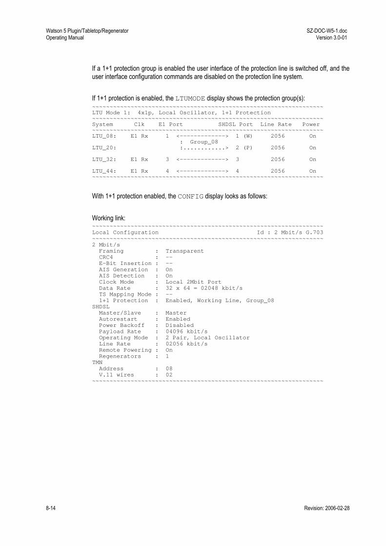
Watson 5 Plugin/Tabletop/Regenerator Operating Manual
SZ-DOC-W5-1.doc Version 3.0-01
8-14 Revision: 2006-02-28
If a 1+1 protection group is enabled the user interface of the protection line is switched off, and the user interface configuration commands are disabled on the protection line system. If 1+1 protection is enabled, the LTUMODE display shows the protection group(s): ~~~~~~~~~~~~~~~~~~~~~~~~~~~~~~~~~~~~~~~~~~~~~~~~~~~~~~~~~~~~~~~~~~ LTU Mode 1: 4x1p, Local Oscillator, 1+1 Protection ~~~~~~~~~~~~~~~~~~~~~~~~~~~~~~~~~~~~~~~~~~~~~~~~~~~~~~~~~~~~~~~~~~ System Clk E1 Port SHDSL Port Line Rate Power ~~~~~~~~~~~~~~~~~~~~~~~~~~~~~~~~~~~~~~~~~~~~~~~~~~~~~~~~~~~~~~~~~~ LTU_08: E1 Rx 1 <-------------> 1 (W) 2056 On : Group_08 LTU_20: :............> 2 (P) 2056 On LTU_32: E1 Rx 3 <-------------> 3 2056 On LTU_44: E1 Rx 4 <-------------> 4 2056 On ~~~~~~~~~~~~~~~~~~~~~~~~~~~~~~~~~~~~~~~~~~~~~~~~~~~~~~~~~~~~~~~~~~
With 1+1 protection enabled, the CONFIG display looks as follows: Working link: ~~~~~~~~~~~~~~~~~~~~~~~~~~~~~~~~~~~~~~~~~~~~~~~~~~~~~~~~~~~~~~~~~~ Local Configuration Id : 2 Mbit/s G.703 ~~~~~~~~~~~~~~~~~~~~~~~~~~~~~~~~~~~~~~~~~~~~~~~~~~~~~~~~~~~~~~~~~~ 2 Mbit/s Framing : Transparent CRC4 : -- E-Bit Insertion : -- AIS Generation : On AIS Detection : On Clock Mode : Local 2Mbit Port Data Rate : 32 x 64 = 02048 kbit/s TS Mapping Mode : -- 1+1 Protection : Enabled, Working Line, Group_08 SHDSL Master/Slave : Master Autorestart : Enabled Power Backoff : Disabled Payload Rate : 04096 kbit/s Operating Mode : 2 Pair, Local Oscillator Line Rate : 02056 kbit/s Remote Powering : On Regenerators : 1 TMN Address : 08 V.11 wires : 02 ~~~~~~~~~~~~~~~~~~~~~~~~~~~~~~~~~~~~~~~~~~~~~~~~~~~~~~~~~~~~~~~~~~

SZ-DOC-W5-1.doc Version 3.0-01
Watson 5 Plugin/Tabletop/Regenerator Operating Manual
Revision: 2006-02-28 8-15
Protection link: ~~~~~~~~~~~~~~~~~~~~~~~~~~~~~~~~~~~~~~~~~~~~~~~~~~~~~~~~~~~~~~~~~~ Local Configuration Id : 2 Mbit/s G.703 ~~~~~~~~~~~~~~~~~~~~~~~~~~~~~~~~~~~~~~~~~~~~~~~~~~~~~~~~~~~~~~~~~~ 2 Mbit/s 1+1 Protection : Enabled, Protection Line, Group_08 SHDSL Master/Slave : Master Autorestart : Enabled Power Backoff : Disabled Payload Rate : 04096 kbit/s Operating Mode : 2 Pair, Local Oscillator Line Rate : 02056 kbit/s Remote Powering : On Regenerators : 1 TMN Address : 08 V.11 wires : 02 ~~~~~~~~~~~~~~~~~~~~~~~~~~~~~~~~~~~~~~~~~~~~~~~~~~~~~~~~~~~~~~~~~~
Note: The GROUP1 and GROUP2 commands are only available on the first system of a plugin
8.2 Fault and Maintenance Management FMM The commands available in the fault and maintenance management menu vary depending on mo-dem hardware, firmware and current configuration. Typing H (for Help) gives a list of available com-mands, e.g. NTU_FMM> H ~~~~~~~~~~~~~~~~~~~~~~~~~~~~~~~~~~~~~~~~~~~~~~~~~~~~~~~~~~~~~~~~~~ DIAGNOSTIC (DIA) Activate / deactivate diagnostic display STATUS Display local system status ALARM Display local alarm status ALARM T Turn alarm trace on/off ACO [ON,OFF] Activate / deactivate alarm cutoff LOOP1 [ON,OFF] m Activate / deactivate Loop 1 for m=[0..480] minutes (0:unlimited) LOOP2 [ON,OFF] m Activate / deactivate Loop 2 at remote unit for m=[0..480] minutes (0:unlimited) RESET Reset system MAIN (M) Return to main menu ~~~~~~~~~~~~~~~~~~~~~~~~~~~~~~~~~~~~~~~~~~~~~~~~~~~~~~~~~~~~~~~~~~
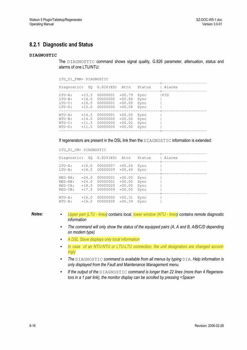
Watson 5 Plugin/Tabletop/Regenerator Operating Manual
SZ-DOC-W5-1.doc Version 3.0-01
8-16 Revision: 2006-02-28
8.2.1 Diagnostic and Status DIAGNOSTIC
The DIAGNOSTIC command shows signal quality, G.826 parameter, attenuation, status and alarms of one LTU/NTU: LTU_01_FMM> DIAGNOSTIC ---------------------------------------------+-------------------- Diagnostic: SQ G.826(ES) Attn Status | Alarms ---------------------------------------------+-------------------- LTU-A: +13.5 00000001 +00.79 Sync |PID LTU-B: +14.0 00000000 +00.86 Sync | LTU-C: +16.5 00000001 +00.00 Sync | LTU-D: +15.0 00000000 +00.08 Sync | ---------------------------------------------+-------------------- NTU-A: +14.5 00000001 +00.00 Sync | NTU-B: +14.0 00000000 +00.00 Sync | NTU-C: +11.5 00000000 +00.02 Sync | NTU-D: +11.5 00000000 +00.00 Sync | ---------------------------------------------+--------------------
If regenerators are present in the DSL link then the DIAGNOSTIC information is extended: LTU_01_CM> DIAGNOSTIC ---------------------------------------------+-------------------- Diagnostic: SQ G.826(ES) Attn Status | Alarms ---------------------------------------------+-------------------- LTU-A: +16.0 00000007 +00.26 Sync | LTU-B: +16.5 00000009 +00.49 Sync | ---------------------------------------------+-------------------- REG-RA: +24.0 00000001 +00.00 Sync | REG-RB: +24.0 00000001 +00.00 Sync | REG-CA: +18.5 00000020 +00.00 Sync | REG-CB: +17.5 00000009 +00.00 Sync | ---------------------------------------------+-------------------- NTU-A: +16.0 00000000 +00.31 Sync | NTU-B: +16.0 00000000 +00.39 Sync |
Notes: • Upper part (LTU - lines) contains local, lower window (NTU - lines) contains remote diagnostic
information • The command will only show the status of the equipped pairs (A, A and B, A/B/C/D depending
on modem type) • A DSL Slave displays only local information • In case of an NTU-NTU or LTU-LTU connection, the unit designators are changed accord-
ingly • The DIAGNOSTIC command is available from all menus by typing DIA. Help information is
only displayed from the Fault and Maintenance Management menu. • If the output of the DIAGNOSTIC command is longer than 22 lines (more than 4 Regenera-
tors in a 1 pair link), the monitor display can be scrolled by pressing <Space>

SZ-DOC-W5-1.doc Version 3.0-01
Watson 5 Plugin/Tabletop/Regenerator Operating Manual
Revision: 2006-02-28 8-17
STATUS
The STATUS command displays the current system status: LTU_01_FMM> STATUS ~~~~~~~~~~~~~~~~~~~~~~~~~~~~~~~~~~~~~~~~~~~~~~~~~~~~~~~~~~~~~~~~~~ Local System Status V3.0 ~~~~~~~~~~~~~~~~~~~~~~~~~~~~~~~~~~~~~~~~~~~~~~~~~~~~~~~~~~~~~~~~~~ SYNC-A: 02 OPS-A: 01 PID-A: 01 PWR-A: +13.50 UPS: 01 SYNC-B: 02 OPS-B: 01 PID-B: 02 PWR-B: +13.50 ~~~~~~~~~~~~~~~~~~~~~~~~~~~~~~~~~~~~~~~~~~~~~~~~~~~~~~~~~~~~~~~~~~
Attributes: SYNC
00 01 02 03 04 05 06 07
Status of SHDSL synchronization state machine of loop A according to ETSI TS 101 524. Out of Sync State State 0 In Sync State State 1 State 2 State 3 State 4 State 5
OPS 00 01 10 18 80
Operational mode of the transceiver Idle Mode Data Mode Startup handshake in progress Startup training in progress Local analog loopback
PID n Pair Identification when 4p operation is enabled PWR n Transmit power of each channel [dBm] UPS 01
02 Unit Power Source 01: locally powered 02: remotely powered Available in Firmware release 3.x

Watson 5 Plugin/Tabletop/Regenerator Operating Manual
SZ-DOC-W5-1.doc Version 3.0-01
8-18 Revision: 2006-02-28
PRA (PRA mode only)
00 01 02 03 04 05 06 07 08 09 10 11 12 13 14 15 16 17 18 19
Current state of the digital section (DS) according to ETS 300 233 section 9.4 (only the states possible in NT1 & LT mode are displayed). NTU dying NTU dying & FV3/FC5 NTU dying & FC4 NTU dying & FC4 & FV3/FC5 NTU dying & AIS NTU dying & AIS & FC4 Normal function FC4 FV3/FC5 FV3/FC5 & FC4 Loopback 1 Loopback 1 & FC4 Loopback 2 Loopback 2 & FC4 Loopback 1 & NTU dying Loopback 1 & NTU dying & FC4 Loopback 2 & NTU dying Loopback 2 & NTU dying & FC4 AIS AIS & FC4
Note: In multipair modems the status values will be displayed per pair with suffix –A, -B, -C and -D
If used with the Regenerator the output of the STATUS command is somewhat different: REG_01_FMM_REMOTE> STATUS ~~~~~~~~~~~~~~~~~~~~~~~~~~~~~~~~~~~~~~~~~~~~~~~~~~~~~~~~~~~~~~~~~~ Local System Status V1.1 ~~~~~~~~~~~~~~~~~~~~~~~~~~~~~~~~~~~~~~~~~~~~~~~~~~~~~~~~~~~~~~~~~~ SYNC-RA: 02 OPS-RA: 01 PID-RA: 01 PWR-RA: +13.50 RPV-A: 110.2 SYNC-RB: 02 OPS-RB: 01 PID-RB: 02 PWR-RB: +13.50 RPV-B: 110.2 SYNC-CA: 02 OPS-CA: 01 PID-CA: 01 PWR-CA: +13.50 SYNC-CB: 02 OPS-CB: 01 PID-CB: 02 PWR-CB: +13.50 ~~~~~~~~~~~~~~~~~~~~~~~~~~~~~~~~~~~~~~~~~~~~~~~~~~~~~~~~~~~~~~~~~~
Attributes: RPV-A RPV-B
Remote Power Voltage of loop A and B (in Volts)
Note: To display regenerator status you have to log on to the remote monitor terminal of a Regenerator
with the CONNECT command.

SZ-DOC-W5-1.doc Version 3.0-01
Watson 5 Plugin/Tabletop/Regenerator Operating Manual
Revision: 2006-02-28 8-19
8.2.2 Automatic Protection Switching APS
The APS command displays the current status of the APS groups: ~~~~~~~~~~~~~~~~~~~~~~~~~~~~~~~~~~~~~~~~~~~~~~~~~~~~~~~~~~~~~~~~~~ APS Status (1+1 protection, bidirectional, non-revertive) ~~~~~~~~~~~~~~~~~~~~~~~~~~~~~~~~~~~~~~~~~~~~~~~~~~~~~~~~~~~~~~~~~~ Group Number : 1 Name : Group_08 Config Status : 01 (active) Command Status : 01 (noCmd) Current Status : 00 Switched Line : Protection Line Working Line Line : LTU_08 Switchovers : 00000000 Last Switchover : 00000000 Switchover Seconds : 00000000 Protection Line Line : LTU_20 Switchovers : 00000000 Last Switchover : 00000000 ~~~~~~~~~~~~~~~~~~~~~~~~~~~~~~~~~~~~~~~~~~~~~~~~~~~~~~~~~~~~~~~~~~
Group Attributes: Number Group number (1 or 2) Name Group name (defined by system address) Config Status Current configuration: 1 (active, enabled) or 2 (not in service,
disabled) Command Status Current APS command, cf. Table 8-5 Current Status Current status:
00: normal operation 01: mode mismatch: the remote unit does not support APS 02: channel mismatch: working line and protection line are
not connected to the same protection group on the re-mote unit or pairs of the working line have been con-nected to pairs of the protection line
Switched Line The line currently carrying traffic (working line or protection line)
Line Attributes Line System address Switchovers Number of switchovers Last Switchover Time of last switchover Switchover Sec-onds
Cumulative protection switching duration time in seconds, i. e. the cumulative number of seconds that service was carried on the protection line.
Note: The counters start counting as soon as the APS group is activated (GROUPn ON). They are reset
with the RESETAPS command or by deactivating the group (GROUPn OFF).

Watson 5 Plugin/Tabletop/Regenerator Operating Manual
SZ-DOC-W5-1.doc Version 3.0-01
8-20 Revision: 2006-02-28
APS n
APS n issues a command to the APS group:
Command (n) Result 2 clear: clears any active command 3 Lockout of protection: Prevents the working line from switching to the protection
line 4 Forced switch work to protect: switches from the working line to the protection line
regardless of the current state of the protection line 5 Forced switch protect to work: switches from the protection line to the working line
regardless of the current state of the working line 6 Manual switch work to protect: switches from the working line to the protection line
unless there is a failure on the protection line 7 Manual switch protect to work: switches from the protection line to the working line
unless there is a failure on the working line 8 Exercise: accepts and acknowledges a switchover command without actually exe-
cuting the switchover
Table 8-5: APS commands
RESETAPS
Resets the APS counters.
8.2.3 Alarm and Alarm History ACO
The ACO (Alarm Cut Off) command enables or disables the alarm relays. When ACO is 'on', all alarms are disabled and the alarm-relays are inactive. The local alarm LED signals a non-urgent alarm. LTU_01_FMM> ACO ON 11:03:10 alarm cutoff activated LTU_01_FMM> ACO OFF 11:11:70 alarm cutoff deactivated
ALARM
The ALARM command displays the current alarm status: LTU_01_FMM> ALARM ~~~~~~~~~~~~~~~~~~~~~~~~~~~~~~~~~~~~~~~~~~~~~~~~~~~~~~~~~~~~~~~~~~ Local Alarm Status ~~~~~~~~~~~~~~~~~~~~~~~~~~~~~~~~~~~~~~~~~~~~~~~~~~~~~~~~~~~~~~~~~~ LOS-S:off AIS-S:off LOOP1:off ACO:off EXT-LOC:off LFA-S:off BER-S:off LOOP2:off ALB:off LOOPREG:off LOSW-A:off BER-A:off SEG-A:off CLD-A:off BERT:off ~~~~~~~~~~~~~~~~~~~~~~~~~~~~~~~~~~~~~~~~~~~~~~~~~~~~~~~~~~~~~~~~~~
Parameter: T Turns alarm trace on / off. When ALARM T is active then the screen is con-
tinuously updated with active alarms. Below any change in alarm status is dis-played with a time stamp counted in min:sec:millisec from the last system reset. The alarm changes will be displayed until ALARM T is deactivated by entering ALARM T a second time or until the FMM menu is left

SZ-DOC-W5-1.doc Version 3.0-01
Watson 5 Plugin/Tabletop/Regenerator Operating Manual
Revision: 2006-02-28 8-21
Attributes: ACO Alarm cutoff AIS-S AIS (Alarm Indication Signal) detected at subscriber (E1) side AIS-V3 Alarm indication signal at V3-reference point (PRA mode) ALB Analog loopback BER-A SHDSL block-error-rate according G.826 ≥ 30% on channel A BER-B SHDSL block-error-rate according G.826 ≥ 30% on channel B BER-S Excessive Block Error Rate on subscriber side
If CRC4 enabled : BER-S = on if more than 805 CRC4 Errors per second. If CRC4 disabled : BER-S = on if more than 28 FAS Errors per second.
BERT BER test activated CLD-A Current limit detection on channel A CLD-B Current limit detection on channel B DTR-S Status of DTR (Data Terminal Ready) Handshake Signal in V.35/V.36 mode:
DTR Signal is detected as ON: DTR-S Alarm is off DTR Signal is detected as OFF: DTR-S Alarm is on In X.21 mode the DTR-S alarm depends on the state of Control-signal C. DTR-S alarm will always be off in X.21 mode if handshake is set to OFF.
EXT-LOC Loss of external clock LFA-S Loss of frame alignment at subscriber (E1) side LFA-V3 Loss of frame alignment at V3-reference point (PRA mode) LOC-S Loss Of Clock (When Local Clock mode is selected). Only displayed if an nx64
interface is available on the modem. LOC is also active when the incoming clock bitrate is not equal to the programmed bitrate (n). Clock master present with correct bitrate (Status: off) Clock master not present and/or bitrate mismatch (Status: on)
LOOP1 SHDSL test loop 1 active (see section 0) LOOP2 SHDSL test loop 2 active LOOPREG Regenerator loopback active LOS-S Loss of signal at subscriber (E1) side LOSW-A Loss of Sync Defect (LOSW defect) on channel A LOSW-B Loss of Sync Defect (LOSW defect) on channel B PID Display a pair mismatch when operating in 4p mode (master only) SEG-A Segment defect alarm indication if regenerators present on channel A SEG-B Segment defect alarm indication if regenerators present on channel B
Note: When both an nx64 kbit/s and an E1 interface are equipped, the ALARM command displays first
the E1/PRA alarms and then the nx64 kbit/s alarms.

Watson 5 Plugin/Tabletop/Regenerator Operating Manual
SZ-DOC-W5-1.doc Version 3.0-01
8-22 Revision: 2006-02-28
ALARM H
The ALARM H command displays alarm events of the past with a time stamp based on the inter-nal system time of the LTU. The time stamp shows the number of days elapsed and the system time in format day:hour:minute at the occurrence instant of the event. This relative LTU system time is set to zero by each RESET command or power-on. LTU_10_FMM> ALARM H ~~~~~~~~~~~~~~~~~~~~~~~~~~~~~~~~~~~~~~~~~~~~~~~~~~~~~~~~~~~~~~~~~~ Alarm History (day:hour:min) ~~~~~~~~~~~~~~~~~~~~~~~~~~~~~~~~~~~~~~~~~~~~~~~~~~~~~~~~~~~~~~~~~~ +0:00:00 LOS-S alarm on +0:00:00 remote alarm on +0:00:02 LOS-S alarm off +0:00:02 remote alarm off ~~~~~~~~~~~~~~~~~~~~~~~End of Alarm History~~~~~~~~~~~~~~~~~~~~~~~ LTU_10_FMM>
Notes: • Power-on or RESET command resets the internal system time clears stored events.
The alarm history is limited to 500 alarm messages per system / DSL link and a maximum col-lection time of about 240h.
• The current time is displayed if alarm history is empty. Use ALARM H hh:mm to define a time offset used when calculating timestamps. On basis of the time offset entered by the user and the LTUs internal system time the event is marked with the number of days elapsed since the last RESET or power-on plus the time offset. LTU_10_FMM> ALARM H 14:23 ~~~~~~~~~~~~~~~~~~~~~~~~~~~~~~~~~~~~~~~~~~~~~~~~~~~~~~~~~~~~~~~~~~ Alarm History (day:hour:min) ~~~~~~~~~~~~~~~~~~~~~~~~~~~~~~~~~~~~~~~~~~~~~~~~~~~~~~~~~~~~~~~~~~ +0:14:18 LOS-S alarm on +0:14:18 remote alarm on +0:14:20 LOS-S alarm off +0:14:20 remote alarm off ~~~~~~~~~~~~~~~~~~~~~~~End of Alarm History~~~~~~~~~~~~~~~~~~~~~~~
Note: Once a time adjustment is made with the ALARM H command, this adjustment is stored in the LTU. Repeated ALARM H command executions without a time adjustment will still display time stamps calculated on basis of the time declaration previously entered. Example: If ALARM H is executed three days after the time adjustment: LTU_10_FMM> ALARM H ~~~~~~~~~~~~~~~~~~~~~~~~~~~~~~~~~~~~~~~~~~~~~~~~~~~~~~~~~~~~~~~~~~ Alarm History (day:hour:min) ~~~~~~~~~~~~~~~~~~~~~~~~~~~~~~~~~~~~~~~~~~~~~~~~~~~~~~~~~~~~~~~~~~ -3:14:18 LOS-S alarm on -3:14:18 remote alarm on -3:14:20 LOS-S alarm off -3:14:20 remote alarm off ~~~~~~~~~~~~~~~~~~~~~~~End of Alarm History~~~~~~~~~~~~~~~~~~~~~~~
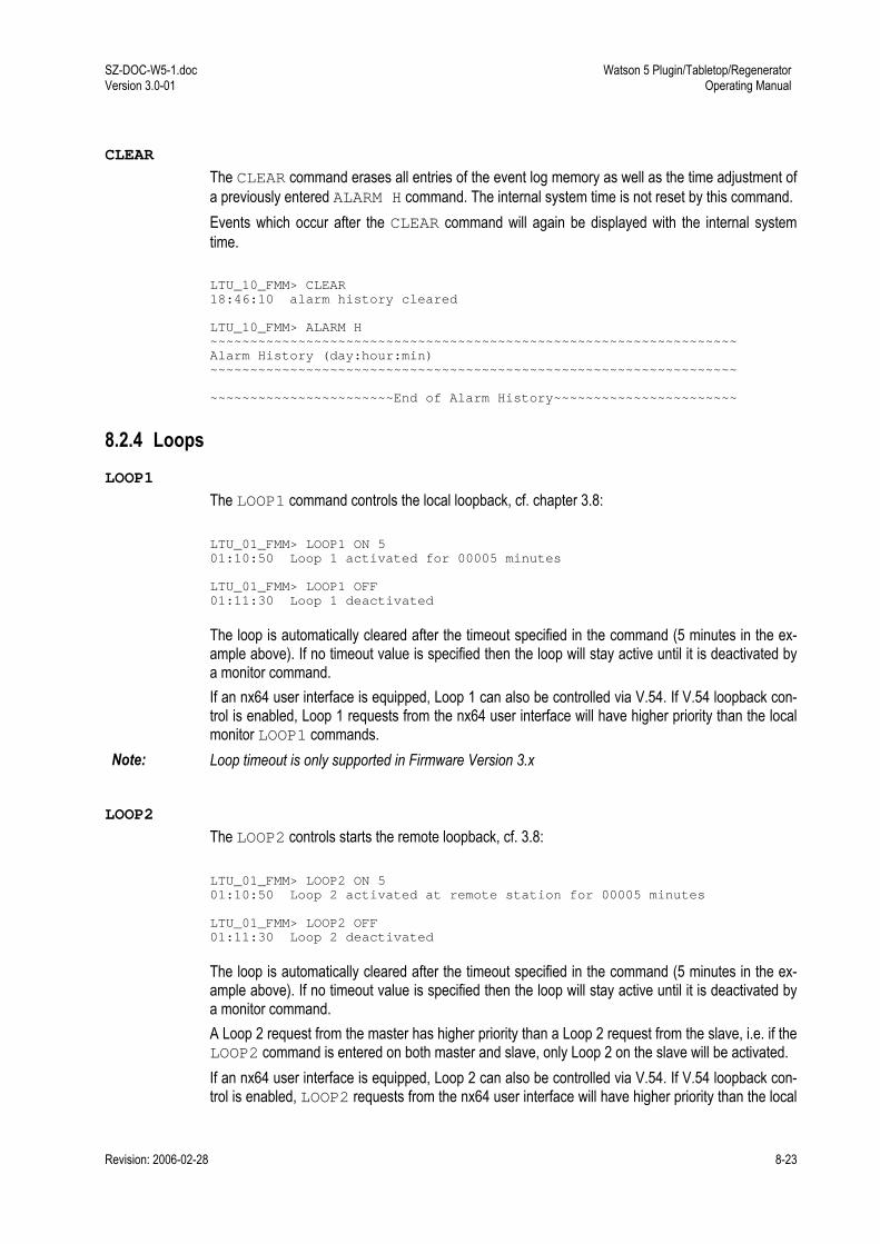
SZ-DOC-W5-1.doc Version 3.0-01
Watson 5 Plugin/Tabletop/Regenerator Operating Manual
Revision: 2006-02-28 8-23
CLEAR
The CLEAR command erases all entries of the event log memory as well as the time adjustment of a previously entered ALARM H command. The internal system time is not reset by this command. Events which occur after the CLEAR command will again be displayed with the internal system time. LTU_10_FMM> CLEAR 18:46:10 alarm history cleared LTU_10_FMM> ALARM H ~~~~~~~~~~~~~~~~~~~~~~~~~~~~~~~~~~~~~~~~~~~~~~~~~~~~~~~~~~~~~~~~~~ Alarm History (day:hour:min) ~~~~~~~~~~~~~~~~~~~~~~~~~~~~~~~~~~~~~~~~~~~~~~~~~~~~~~~~~~~~~~~~~~ ~~~~~~~~~~~~~~~~~~~~~~~End of Alarm History~~~~~~~~~~~~~~~~~~~~~~~
8.2.4 Loops LOOP1
The LOOP1 command controls the local loopback, cf. chapter 3.8: LTU_01_FMM> LOOP1 ON 5 01:10:50 Loop 1 activated for 00005 minutes LTU_01_FMM> LOOP1 OFF 01:11:30 Loop 1 deactivated
The loop is automatically cleared after the timeout specified in the command (5 minutes in the ex-ample above). If no timeout value is specified then the loop will stay active until it is deactivated by a monitor command. If an nx64 user interface is equipped, Loop 1 can also be controlled via V.54. If V.54 loopback con-trol is enabled, Loop 1 requests from the nx64 user interface will have higher priority than the local monitor LOOP1 commands.
Note: Loop timeout is only supported in Firmware Version 3.x
LOOP2
The LOOP2 controls starts the remote loopback, cf. 3.8: LTU_01_FMM> LOOP2 ON 5 01:10:50 Loop 2 activated at remote station for 00005 minutes LTU_01_FMM> LOOP2 OFF 01:11:30 Loop 2 deactivated
The loop is automatically cleared after the timeout specified in the command (5 minutes in the ex-ample above). If no timeout value is specified then the loop will stay active until it is deactivated by a monitor command. A Loop 2 request from the master has higher priority than a Loop 2 request from the slave, i.e. if the LOOP2 command is entered on both master and slave, only Loop 2 on the slave will be activated. If an nx64 user interface is equipped, Loop 2 can also be controlled via V.54. If V.54 loopback con-trol is enabled, LOOP2 requests from the nx64 user interface will have higher priority than the local

Watson 5 Plugin/Tabletop/Regenerator Operating Manual
SZ-DOC-W5-1.doc Version 3.0-01
8-24 Revision: 2006-02-28
monitor LOOP2 commands. In case of remote Loop 2 requests, the master has higher priority that the slave.
Notes • LOOP2 is only possible from master side in Firmware Versions 1.x and 2.x. • Loop timeout is only supported in Firmware Version 3.x • LOOP2 is not supported if the card is configured in Multipoint mode
LOOPREGn
The LOOPREGn command controls the loopback in the nth regenerator, cf. chapter 3.8: LTU_01_FMM> LOOPREG1 ON 5 29:25:70 regenerator (1) loopback activated for 00005 minutes LTU_01_FMM> LOOPREG1 OFF 29:26:40 regenerator (1) loopback activated
Note • Loop timeout is only supported in Firmware Version 3.x
8.2.5 Reset Commands RESET
Typing RESET restarts the system unit. LTU_01_FMM> RESET 05:06:10 system reset
Note: • On a dual and quad LTUs all DSL systems will be reset.
RESETCARD
The RESETCARD command initiates a complete hardware and software reset of the card. This means that all links of a multi-link LTU are affected (not just the one the Monitor is currently con-nected to). The RESETCARD must be confirmed before it is processed: LTU_01_FMM> RESETCARD *** Warning: this command will reset both SHDSL links of the Dual LTU enter reset command again to confirm (timeout after 30 sec) LTU_01_FMM> RESETCARD 46:35:30 reset command confirmed 46:35:30 system reset

SZ-DOC-W5-1.doc Version 3.0-01
Watson 5 Plugin/Tabletop/Regenerator Operating Manual
Revision: 2006-02-28 8-25
8.3 Performance Management PM LTU_01_PM> H ~~~~~~~~~~~~~~~~~~~~~~~~~~~~~~~~~~~~~~~~~~~~~~~~~~~~~~~~~~~~~~~~~~ G826 Display local SHDSL G.826 parameter G826 C Display local SHDSL G.826 parameter continuously G826 E1 Display local E1 G.826 parameter G826 E1 C Display local E1 G.826 parameter continuously RESETG826 Reset G.826 error performance parameter STARTBER m dir p Start BER test for m minutes dir=[0..3] p=[0,1]) STOPBER Stop BER test READBER Display results of BER test READBER C Display results of BER test continuously RESETBER Reset BER counters M(AIN) Return to main menu ~~~~~~~~~~~~~~~~~~~~~~~~~~~~~~~~~~~~~~~~~~~~~~~~~~~~~~~~~~~~~~~~~~
8.3.1 G.826 Statistics G826
The G826 command displays the ITU-T G.826 error performance parameters on the DSL line side of the local and remote DSL unit: LTU_01_PM> G826 ~~~~~~~~~~~~~~~~~~~~~~~~~~~~~~~~~~~~~~~~~~~~~~~~~~~~~~~~~~~~~~~~~~ G.826 Error Performance : CRC6 A ~~~~~~~~~~~~~~~~~~~~~~~~~~~~~~~~~~~~~~~~~~~~~~~~~~~~~~~~~~~~~~~~~~ Errored blocks : 00000000 Errored seconds : 00000000 Severely errored seconds : 00000000 ESR [%] : 0.00 SESR [%] : 0.00 BBER [%] : 0.00 Available time : 00624483 Unavailable time : 00000024 ~~~~~~~~~~~~~~~~~~~~~~~~~~~~~~~~~~~~~~~~~~~~~~~~~~~~~~~~~~~~~~~~~~ Parameter: C Updates the G.826 parameters continuously
Attributes: CRC6 Cyclic redundancy check indicating errored blocks, are being
received on the local DSL side Errored blocks (EB)
A block in which one or more bits are in error
Errored seconds (ES)
A one second period with one or more errored blocks. SES de-fined below is a subset of ES
Severely errored second (SES)
A one second period which contains >=30% errored blocks
Background block error (BBE)
An errored block not occurring as part of an SES
Errored second ratio (ESR)
The ratio of ES to total seconds in available time during a fixed measurement interval
Severely errored second ratio SESR
The ratio of SES to total seconds in available time during a fixed measurement interval

Watson 5 Plugin/Tabletop/Regenerator Operating Manual
SZ-DOC-W5-1.doc Version 3.0-01
8-26 Revision: 2006-02-28
Background block error ratio (BBER)
The ratio of errored blocks to total blocks during a fixed meas-urement interval, excluding all blocks during SES and unavail-able time
G826 E1
The G826 command can also display the G.826 parameters for the E1 interface. Depending on the current configuration of the interface the G.826 values are calculated differently. If CRC4 mode is on, the following parameters are displayed: LTU_01_PM> G826 E1 ~~~~~~~~~~~~~~~~~~~~~~~~~~~~~~~~~~~~~~~~~~~~~~~~~~~~~~~~~~~~~~~~~~ G.826 Error Performance : CRC4 E-Bit ~~~~~~~~~~~~~~~~~~~~~~~~~~~~~~~~~~~~~~~~~~~~~~~~~~~~~~~~~~~~~~~~~~ Errored Blocks : 00000000 00000000 Errored seconds : 00000000 00000000 Severely errored seconds : 00000000 00000000 ESR [%] : 0.00 0.00 SESR [%] : 0.00 0.00 BBER [%] : 0.00 0.00 Available time : 00524129 00524129 Unavailable time : 00000024 00000024 ~~~~~~~~~~~~~~~~~~~~~~~~~~~~~~~~~~~~~~~~~~~~~~~~~~~~~~~~~~~~~~~~~~ LTU_01_PM>
Parameter: C Updates the G.826 parameters continuously
Attributes: CRC4 Cyclic redundancy check indicating errored sub-multiframes received on the local
2Mbit/s E1 side. E-bit CRC-4 indication bit denoting received errored sub-multiframes on the 2Mbit/s E1
side.
If CRC4 mode is off, the following parameters are displayed: LTU_01_PM> G826 E1 ~~~~~~~~~~~~~~~~~~~~~~~~~~~~~~~~~~~~~~~~~~~~~~~~~~~~~~~~~~~~~~~~~~ G.826 Error Performance : FAS ~~~~~~~~~~~~~~~~~~~~~~~~~~~~~~~~~~~~~~~~~~~~~~~~~~~~~~~~~~~~~~~~~~ Errored blocks : 00000000 Errored seconds : 00000000 Severely errored seconds : 00000000 ESR [%] : 0.00 SESR [%] : 0.00 BBER [%] : 0.00 Available time : 00009841 Unavailable time : 00000024 ~~~~~~~~~~~~~~~~~~~~~~~~~~~~~~~~~~~~~~~~~~~~~~~~~~~~~~~~~~~~~~~~~~
Attributes: FAS Errored Frame Alignment Signal received on the 2Mbit/s E1 side. The criteria for
severely errored seconds (SES) is 28 FAS-Errors per second (in accordance to G.821).
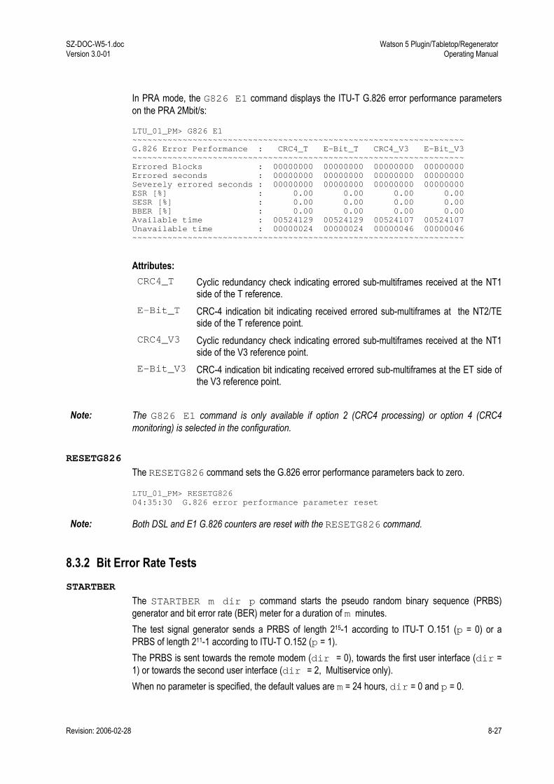
SZ-DOC-W5-1.doc Version 3.0-01
Watson 5 Plugin/Tabletop/Regenerator Operating Manual
Revision: 2006-02-28 8-27
In PRA mode, the G826 E1 command displays the ITU-T G.826 error performance parameters on the PRA 2Mbit/s: LTU_01_PM> G826 E1 ~~~~~~~~~~~~~~~~~~~~~~~~~~~~~~~~~~~~~~~~~~~~~~~~~~~~~~~~~~~~~~~~~~ G.826 Error Performance : CRC4_T E-Bit_T CRC4_V3 E-Bit_V3 ~~~~~~~~~~~~~~~~~~~~~~~~~~~~~~~~~~~~~~~~~~~~~~~~~~~~~~~~~~~~~~~~~~ Errored Blocks : 00000000 00000000 00000000 00000000 Errored seconds : 00000000 00000000 00000000 00000000 Severely errored seconds : 00000000 00000000 00000000 00000000 ESR [%] : 0.00 0.00 0.00 0.00 SESR [%] : 0.00 0.00 0.00 0.00 BBER [%] : 0.00 0.00 0.00 0.00 Available time : 00524129 00524129 00524107 00524107 Unavailable time : 00000024 00000024 00000046 00000046 ~~~~~~~~~~~~~~~~~~~~~~~~~~~~~~~~~~~~~~~~~~~~~~~~~~~~~~~~~~~~~~~~~~
Attributes: CRC4_T Cyclic redundancy check indicating errored sub-multiframes received at the NT1
side of the T reference. E-Bit_T CRC-4 indication bit indicating received errored sub-multiframes at the NT2/TE
side of the T reference point. CRC4_V3 Cyclic redundancy check indicating errored sub-multiframes received at the NT1
side of the V3 reference point. E-Bit_V3 CRC-4 indication bit indicating received errored sub-multiframes at the ET side of
the V3 reference point.
Note: The G826 E1 command is only available if option 2 (CRC4 processing) or option 4 (CRC4 monitoring) is selected in the configuration.
RESETG826
The RESETG826 command sets the G.826 error performance parameters back to zero. LTU_01_PM> RESETG826 04:35:30 G.826 error performance parameter reset
Note: Both DSL and E1 G.826 counters are reset with the RESETG826 command.
8.3.2 Bit Error Rate Tests STARTBER
The STARTBER m dir p command starts the pseudo random binary sequence (PRBS) generator and bit error rate (BER) meter for a duration of m minutes. The test signal generator sends a PRBS of length 215-1 according to ITU-T O.151 (p = 0) or a PRBS of length 211-1 according to ITU-T O.152 (p = 1). The PRBS is sent towards the remote modem (dir = 0), towards the first user interface (dir = 1) or towards the second user interface (dir = 2, Multiservice only). When no parameter is specified, the default values are m = 24 hours, dir = 0 and p = 0.
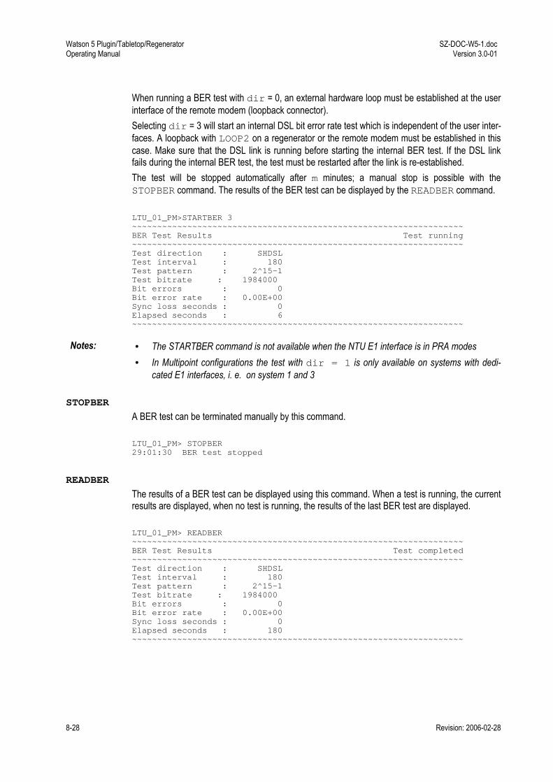
Watson 5 Plugin/Tabletop/Regenerator Operating Manual
SZ-DOC-W5-1.doc Version 3.0-01
8-28 Revision: 2006-02-28
When running a BER test with dir = 0, an external hardware loop must be established at the user interface of the remote modem (loopback connector). Selecting dir = 3 will start an internal DSL bit error rate test which is independent of the user inter-faces. A loopback with LOOP2 on a regenerator or the remote modem must be established in this case. Make sure that the DSL link is running before starting the internal BER test. If the DSL link fails during the internal BER test, the test must be restarted after the link is re-established. The test will be stopped automatically after m minutes; a manual stop is possible with the STOPBER command. The results of the BER test can be displayed by the READBER command. LTU_01_PM>STARTBER 3 ~~~~~~~~~~~~~~~~~~~~~~~~~~~~~~~~~~~~~~~~~~~~~~~~~~~~~~~~~~~~~~~~~~ BER Test Results Test running ~~~~~~~~~~~~~~~~~~~~~~~~~~~~~~~~~~~~~~~~~~~~~~~~~~~~~~~~~~~~~~~~~~ Test direction : SHDSL Test interval : 180 Test pattern : 2^15-1 Test bitrate : 1984000 Bit errors : 0 Bit error rate : 0.00E+00 Sync loss seconds : 0 Elapsed seconds : 6 ~~~~~~~~~~~~~~~~~~~~~~~~~~~~~~~~~~~~~~~~~~~~~~~~~~~~~~~~~~~~~~~~~~
Notes: • The STARTBER command is not available when the NTU E1 interface is in PRA modes • In Multipoint configurations the test with dir = 1 is only available on systems with dedi-
cated E1 interfaces, i. e. on system 1 and 3
STOPBER
A BER test can be terminated manually by this command. LTU_01_PM> STOPBER 29:01:30 BER test stopped
READBER
The results of a BER test can be displayed using this command. When a test is running, the current results are displayed, when no test is running, the results of the last BER test are displayed. LTU_01_PM> READBER ~~~~~~~~~~~~~~~~~~~~~~~~~~~~~~~~~~~~~~~~~~~~~~~~~~~~~~~~~~~~~~~~~~ BER Test Results Test completed ~~~~~~~~~~~~~~~~~~~~~~~~~~~~~~~~~~~~~~~~~~~~~~~~~~~~~~~~~~~~~~~~~~ Test direction : SHDSL Test interval : 180 Test pattern : 2^15-1 Test bitrate : 1984000 Bit errors : 0 Bit error rate : 0.00E+00 Sync loss seconds : 0 Elapsed seconds : 180 ~~~~~~~~~~~~~~~~~~~~~~~~~~~~~~~~~~~~~~~~~~~~~~~~~~~~~~~~~~~~~~~~~~
SZ-DOC-W5-1.doc Version 3.0-01
Watson 5 Plugin/Tabletop/Regenerator Operating Manual
Revision: 2006-02-28 8-29
RESETBER
The RESETBER command resets the error and time counters of a BER test. LTU_01_PM> RESETBER 29:01:30 BER counters reset
8.4 Security and Remote Management SM LTU_08_SM> H ~~~~~~~~~~~~~~~~~~~~~~~~~~~~~~~~~~~~~~~~~~~~~~~~~~~~~~~~~~~~~~~~~~ CONNECT adr (CON) Connect remote terminal (adr=[2..10]) 2=NTU remote, 3=REG 1, 4=REG 2, etc. DISCONNECT (DIS) Disconnect remote terminal(s) alternatively press <Esc> RHM Read HM-Code RCHM [I,C] Read CHM-Code (I=initial, C=current) MAIN (M) Return to main menu ~~~~~~~~~~~~~~~~~~~~~~~~~~~~~~~~~~~~~~~~~~~~~~~~~~~~~~~~~~~~~~~~~~
8.4.1 Connection control CONNECT
The CONNECT n command sets a connection to a remote unit for configuration purposes. A re-mote unit is either a regenerator or the NTU. Remote units are addressed as per TS 101 524, cf. Table 8-6. If no address is entered the CONNECT command will connect to the NTU. Device Unit Address LTU, DSL Master 1 NTU, DSL Slave 2 Regenerator 3-10
Table 8-6: SHDSL EOC Message Address
DISCONNECT
The DISCONNECT command breaks the connection to the remote unit. If no remote terminal is currently connected, the DISCONNECT command lists all remote units currently available. In-stead of typing DISCONNECT, the ESC key can be used to return to the local terminal in a more convenient way.
Note: The CONNECT and DISCONNECT commands are available from all sub-menus, but are not dis-played in the respective help screens.
Watson 5 Plugin/Tabletop/Regenerator Operating Manual
SZ-DOC-W5-1.doc Version 3.0-01
8-30 Revision: 2006-02-28
8.4.2 Inventory RCHM
The RCHM command reads out the CHM code of the connected device. The CHM code includes the hardware type identifier, information about hardware and software revisions as well as the de-fault delivery settings. With Firmware 3.x two CHM Codes are available: • RCHM I will read the initial CHM code. The initial CHM code is set at production time and
never changed. • RCHM C reads the current CHM code. The current CHM code is updated with new firmware
downloaded to the modem.
RHM
The RHM command reads out the HM code from the EEPROM of the connected device and dis-plays it on the terminal. The HM code includes the serial number of the device, as well as information about manufacturer and warranty.
8.4.3 Password Commands CHANGE PASSWORD
The CHANGE PASSWORD command is used to change a password. The old password has to be known to change it. The new password must be entered twice to confirm it. NTU_SM> H ~~~~~~~~~~~~~~~~~~~~~~~~~~~~~~~~~~~~~~~~~~~~~~~~~~~~~~~~~~~~~~~~~~ DISCONNECT (DIS) Disconnect remote terminal(s) CHANGE PASSWORD Change password for monitor protection CLEAR PASSWORD Disable monitor password protection LOGOFF Log off from monitor RHM Read HM-Code RCHM Read CHM-Code MAIN (M) Return to main menu ~~~~~~~~~~~~~~~~~~~~~~~~~~~~~~~~~~~~~~~~~~~~~~~~~~~~~~~~~~~~~~~~~~ NTU_SM> CHANGE PASSWORD Old password: ****** New password: ****** Confirm new password: ****** 52:11:40 new password set
CLEAR PASSWORD
The CLEAR PASSWORD command clears the currently set password and disables password protection. This is the factory default setting. NTU_SM> CLEAR PASSWORD Old password: ****** 52:12:40 password cleared and monitor protection disabled

SZ-DOC-W5-1.doc Version 3.0-01
Watson 5 Plugin/Tabletop/Regenerator Operating Manual
Revision: 2006-02-28 8-31
DSLSLAVE
The DSLSLAVE command is the only command allowed while password protection is active. The DSLSLAVE command is used to configure a master NTU as a DSL slave to allow a remote termi-nal access in case the password of a master NTU has to be changed or cleared. Monitor Password Protection Enter password: ******** (typed DSLSLAVE) 47:55:90 device is now DSL slave
Password commands through remote terminal Through the remote terminal, i.e. through the DSL EOC the password commands are available without password protection: NTU_SM_REMOTE> H ~~~~~~~~~~~~~~~~~~~~~~~~~~~~~~~~~~~~~~~~~~~~~~~~~~~~~~~~~~~~~~~~~~ DISCONNECT (DIS) Disconnect remote terminal(s) CHANGE PASSWORD Change password for monitor protection CLEAR PASSWORD Disable monitor password protection RHM Read HM-Code RCHM Read CHM-Code MAIN (M) Return to main menu ~~~~~~~~~~~~~~~~~~~~~~~~~~~~~~~~~~~~~~~~~~~~~~~~~~~~~~~~~~~~~~~~~~
In case an NTU has been password protected and the password has been lost the password can be cleared again from an LTU connected to this NTU. If the NTU is configured as DSL master it can be set to DSL slave with the DSLSLAVE command that is available even while password protec-tion is active.
Note: Password commands through remote terminal are not possible if the ACU48 is present in the subrack.
LOGOFF
LOGOFF activates the password protected mode. The previously set password has to be entered before any new monitor commands can be issued via the local terminal. NTU_SM> LOGOFF Monitor Password Protection Enter password:
SET PASSWORD
The SET PASSWORD command allows definition of a password on the NTU. Once a password is set the NTU will go into a protected mode either after the command LOGOFF is issued, after a timeout of 5 minutes or after a restart. While in protected mode no monitor command can be executed from a terminal connected to the local RS-232 port of the NTU before the correct password has been given. All commands are still available on the remote terminal, i.e. on a terminal attached to the LTU which is connected (CONNECT) to the protected NTU. This allows somebody with access to an unprotected LTU to reset the password of a protected NTU. Passwords are always displayed as a series of asterisks (*) on the monitor screen.

Watson 5 Plugin/Tabletop/Regenerator Operating Manual
SZ-DOC-W5-1.doc Version 3.0-01
8-32 Revision: 2006-02-28
NTU_SM> H ~~~~~~~~~~~~~~~~~~~~~~~~~~~~~~~~~~~~~~~~~~~~~~~~~~~~~~~~~~~~~~~~~~ DISCONNECT (DIS) Disconnect remote terminal(s) SET PASSWORD Set a password and enable monitor protection RHM Read HM-Code RCHM Read CHM-Code MAIN (M) Return to main menu ~~~~~~~~~~~~~~~~~~~~~~~~~~~~~~~~~~~~~~~~~~~~~~~~~~~~~~~~~~~~~~~~~~ NTU_SM> SET PASSWORD New password: ****** Confirm new password: ****** 47:52:50 new password set and monitor protection enabled
Notes: • All security related commands (SET PASSWORD, LOGOFF, CLEAR PASSWORD, CHANGE PASSWORD) are only available on NTUs.
• Password protection is disabled by default • Firmware upgrades have no influence on the status of password protection, i.e. if an NTU is
password protected it will stay password protected after a firmware download • The password is not saved in cleartext in the modem configuration database.
8.5 Monitor Commands for minirack operation If an LTU is operated in the Minirack mechanics some additional commands are available to config-ure the TMN interface of the Minirack mechanics. A TMN address can be configured for the LTU with the ADDRESS command. The alternatives of running the TMN communication on a 2- or 4-wire bus can be selected with the V11WIRES com-mand. The list below shows the available commands in the Configuration Management menu of an LTU inserted in a Minirack. RESET command, DEFAULT command and power down have no influence on settings made for the TMN interface. LTU_01_CM> H ~~~~~~~~~~~~~~~~~~~~~~~~~~~~~~~~~~~~~~~~~~~~~~~~~~~~~~~~~~~~~~~~~~ CONFIG Display local configuration G704 [ON,OFF] Set framed mode / transparent mode CRC4 [ON,OFF] Set CRC4 mode on/off EBIT [ON,OFF] Set automatic E-Bit insertion on/off AISGEN [ON,OFF,T] Set AIS generation on/off/transparent AISDET [ON,OFF] Set AIS detection on/off CLK2M [EXT,INT,E1] Select 2Mbit reference clock: external/internal/2Mbit Port MP Display E1 time slot map MP [0..3] Set E1 time slot mapping mode POWER [ON,OFF] Set remote powering on/off RESTART [ON,OFF] Set autorestart on/off BACKOFF [ON,OFF] Set power backoff on/off LINERATE n i a Select line rate (n=[3..36] i=[0,1] a=[0,1]) MODE [1,2] Set SHDSL operating mode ADDRESS slot rack Set TMN address (slot=[1..12] rack=[0..3]) V11WIRES [2,4] Set number of V.11 wires DEFAULT [0..2] Set default configuration MAIN (M) Return to main menu ~~~~~~~~~~~~~~~~~~~~~~~~~~~~~~~~~~~~~~~~~~~~~~~~~~~~~~~~~~~~~~~~~~

SZ-DOC-W5-1.doc Version 3.0-01
Watson 5 Plugin/Tabletop/Regenerator Operating Manual
Revision: 2006-02-28 8-33
ADDRESS
The ADDRESS command allows the user to assign a TMN address to the first DSL interface of a LTU inserted in the Minirack mechanics: LTU_01_CM> ADDRESS 04 01 ~~~~~~~~~~~~~~~~~~~~~~~~~~~~~~~~~~~~~~~~~~~~~~~~~~~~~~~~~~~~~~~~~~ Local Configuration Id : 2 Mbit/s G.703 ~~~~~~~~~~~~~~~~~~~~~~~~~~~~~~~~~~~~~~~~~~~~~~~~~~~~~~~~~~~~~~~~~~ 2 Mbit/s Framing : ITU-T G.704 CRC4 : On E-Bit Insertion : On AIS Generation : On AIS Detection : On External Clock : Disabled Data Rate : 31 x 64 = 01984 kbit/s SHDSL Master/Slave : Master Autorestart : Enabled Power Backoff : Disabled Payload Rate : 02048 kbit/s Operating Mode : 1 Pair Line Rate : 02056 kbit/s Remote Powering : On Regenerators : -- TMN Address : 04 V.11 wires : 04 ~~~~~~~~~~~~~~~~~~~~~~~~~~~~~~~~~~~~~~~~~~~~~~~~~~~~~~~~~~~~~~~~~~
ADDRESS slot rack
slot Identifies the slot number. The LTU will behave as if it had been inserted in a 19" subrack at slot position slot. A number between 1 and 12.
rack Identifies the rack number. The LTU will behave as if it had been inserted in the first (rack = 0) or second (rack = 1) subrack that can be addressed by a CMU.
Notes • On a multilink LTU the address specified in the ADDRESS command identifies the first link.
The other links are addressed by adding 12/24/36 to the address of the first link exactly as if the LTU is inserted in a subrack, cf. Figure 7-2 and Figure 7-3.
• The slot- and rack numbers are combined to a TMN address according to the formula • TMN-address = 48*rack + slot
• The CONFIG command always shows the TMN address, not the rack/slot numbers • Carefully note already used interface address numbers. There is no automatic protection
against multiple LTUs assigned to the same interface address in a set-up with several Minirack LTUs. Two interfaces with the same address on the TMN bus will cause addressing conflicts and the units will not be accessible by the TMN application SW.

Watson 5 Plugin/Tabletop/Regenerator Operating Manual
SZ-DOC-W5-1.doc Version 3.0-01
8-34 Revision: 2006-02-28
V11WIRES
The V11WIRES command allows to switch between 2- or 4-wire communication on the TMN in-terface (EIA-485 bus). LTU_01_CM> V11WIRES 2 ~~~~~~~~~~~~~~~~~~~~~~~~~~~~~~~~~~~~~~~~~~~~~~~~~~~~~~~~~~~~~~~~~~ Local Configuration Id : 2 Mbit/s G.703 ~~~~~~~~~~~~~~~~~~~~~~~~~~~~~~~~~~~~~~~~~~~~~~~~~~~~~~~~~~~~~~~~~~ 2 Mbit/s Framing : ITU-T G.704 CRC4 : On E-Bit Insertion : On AIS Generation : On AIS Detection : On External Clock : Disabled Data Rate : 31 x 64 = 01984 kbit/s SHDSL Master/Slave : Master Autorestart : Enabled Power Backoff : Disabled Payload Rate : 02048 kbit/s Operating Mode : 1 Pair Line Rate : 02056 kbit/s Remote Powering : On Regenerators : -- TMN Address : 04 V.11 wires : 02 ~~~~~~~~~~~~~~~~~~~~~~~~~~~~~~~~~~~~~~~~~~~~~~~~~~~~~~~~~~~~~~~~~~
Notes: • 4-wire communication is recommended for Minirack configurations. • 4-wire communication requires a crossing of Rx and Tx signals between CMU and LTU. 2-wire
communication uses only Rx A and Rx B wires without any crossing.

Revision: 2006-02-28 9-1
9 Diagnostics and Troubleshooting
9.1 Problems and solutions Problem To do: No response from the modem Check your physical serial connection.
Does the PC/cable combination work on other modems? Is it the correct cable? (cf. 11.4) Is the cable grounding connected correctly (floating ground)? Check cable. Check your baud rate, COM1, COM2, etc configuration on the PC (cf. 7.1). Try typing <Control-Q> which is XON and ECHO to re-enable communication to LTUs occasionally left in XOFF state Try selecting the modem using %n, n being modem address.
Strange characters are received in response from the modem.
Check baud rate of PC Try typing <Control-Q> which is XON and ECHO
Problems with E1 clock (fre-quency, drift, slips):
Check configuration: Do not configure the E1 interfaces at both ends to use the receive clock as transmit clock except if one DSL equipment is an LTU using the External Clock option. Otherwise there will be no defined clock.
No startup If both system units are configured as master or as slave, no start-up will occur. To identify the master unit, check if both LEDs are lit. The slave only has the local LED turned on. Check that you are using twisted pair cables up to the end of the DSL RJ-45 connector. Do not use other types of cable.
Watson 5 Plugin/Tabletop/Regenerator Operating Manual
SZ-DOC-W5-1.doc Version 3.0-01
9-2 Revision: 2006-02-28
9.2 Initialization Errors At system startup, various hardware selftests are performed. If any initialization errors occur, the startup procedure will be aborted and the monitor will display an initialization error code in hexa-decimal representation. The table below lists the possible initialization errors and their correspond-ing error codes:.
Error Code Error Variable Initialization Error 0x01 RAM_ERROR Microcontroller RAM test failure 0x02 EEPROM_ERROR EEPROM test failure 0x04 XDSL_ERROR Framer initialization failure 0x08 TCVR_A_ERROR DSL transceiver failure (Loop A) 0x10 TCVR_B_ERROR DSL transceiver failure (Loop B) 0x1000 TCVR_C_ERROR DSL transceiver failure (Loop C) 0x2000 TCVR_D_ERROR DSL transceiver failure (Loop D) 0x40 NX64_ERROR Nx64 interface initialization failure 0x100 CEPT_ERROR E1 interface initialization failure 0x8000 SW_PROTECT_ERROR Software Copyright Protection Error
Table 9-1: Software Initialization Errors
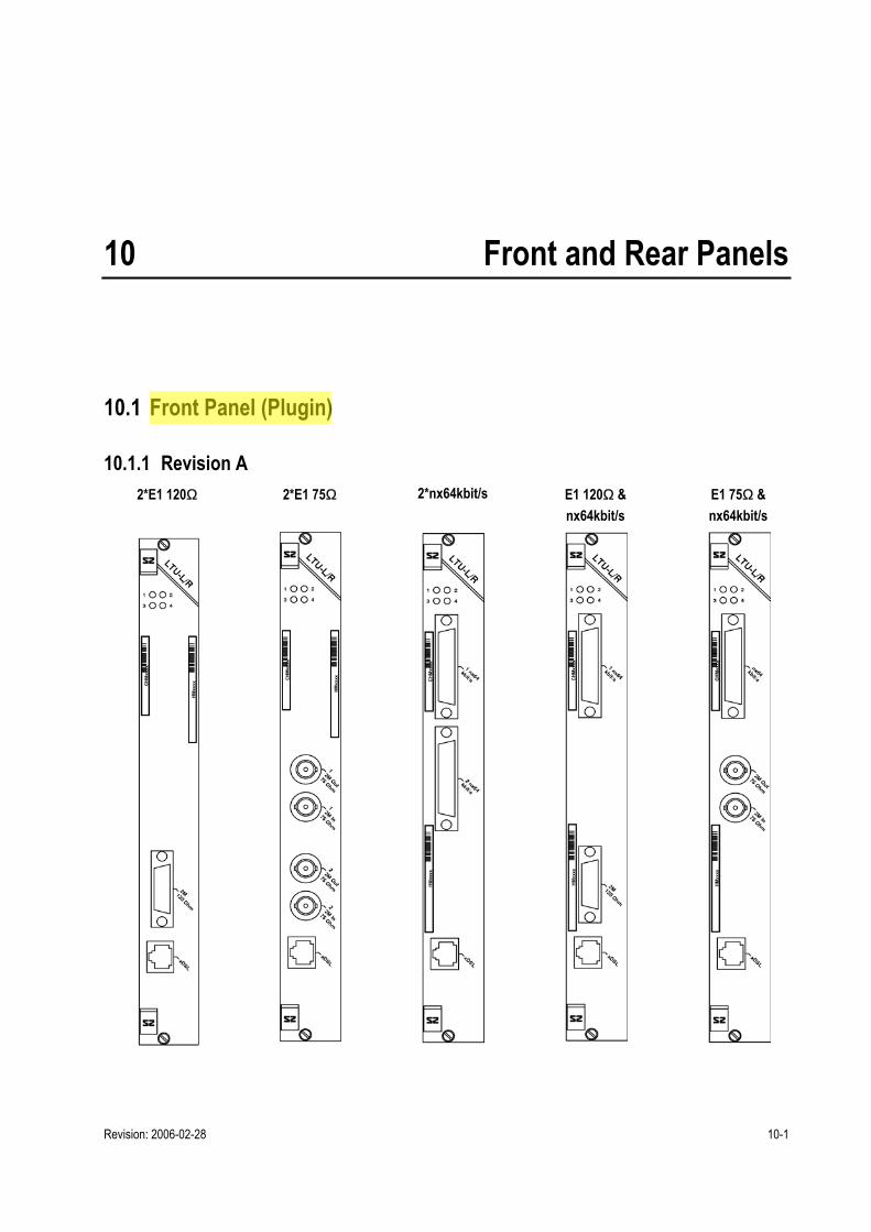
Revision: 2006-02-28 10-1
10 Front and Rear Panels
10.1 Front Panel (Plugin)
10.1.1 Revision A 2*E1 120Ω 2*E1 75Ω 2*nx64kbit/s E1 120Ω &
nx64kbit/s E1 75Ω & nx64kbit/s

Watson 5 Plugin/Tabletop/Regenerator Operating Manual
SZ-DOC-W5-1.doc Version 3.0-01
10-2 Revision: 2006-02-28
10.1.2 Revision B 2 x E1 120Ω 2 x E1 75Ω 4*E1 120Ω 4*E1 75Ω

SZ-DOC-W5-1.doc Version 3.0-01
Watson 5 Plugin/Tabletop/Regenerator Operating Manual
Revision: 2006-02-28 10-3
10.2 Rear Panel (Tabletop)
10.2.1 Revision A E1 120Ω
E1 75Ω
nx64kbit/s
Multiservice E1 120Ω & nx64kbit/s
Multiservice E1 75Ω & nx64kbit/s

Watson 5 Plugin/Tabletop/Regenerator Operating Manual
SZ-DOC-W5-1.doc Version 3.0-01
10-4 Revision: 2006-02-28
10.2.2 Revision B E1 120Ω
E1 75Ω
nx64kbit/s
Multiservice E1 120Ω & nx64kbit/s
Multiservice E1 75Ω & nx64kbit/s

SZ-DOC-W5-1.doc Version 3.0-01
Watson 5 Plugin/Tabletop/Regenerator Operating Manual
Revision: 2006-02-28 11-5
11 Connectors and Cables
11.1 DSL Interface
11.1.1 Connector Connector Type RJ45-8
1 8. . . .
Front View
Figure 11-1: DSL Connector
The connector pin assignment for plugins is as follows: Pin Signal Description 1 LD.a Loop D, tip 2 LD.b Loop D, ring 3 LB.a Loop B, tip 4 LA.a Loop A, tip 5 LA.b Loop A, ring 6 LB.b Loop B, ring
2 x D
SL
7 LC.a Loop C, tip 8 LC.b Loop C, ring
1 x D
SL
4 x D
SL
Table 11-1: DSL connector pin assignment (Plugin)
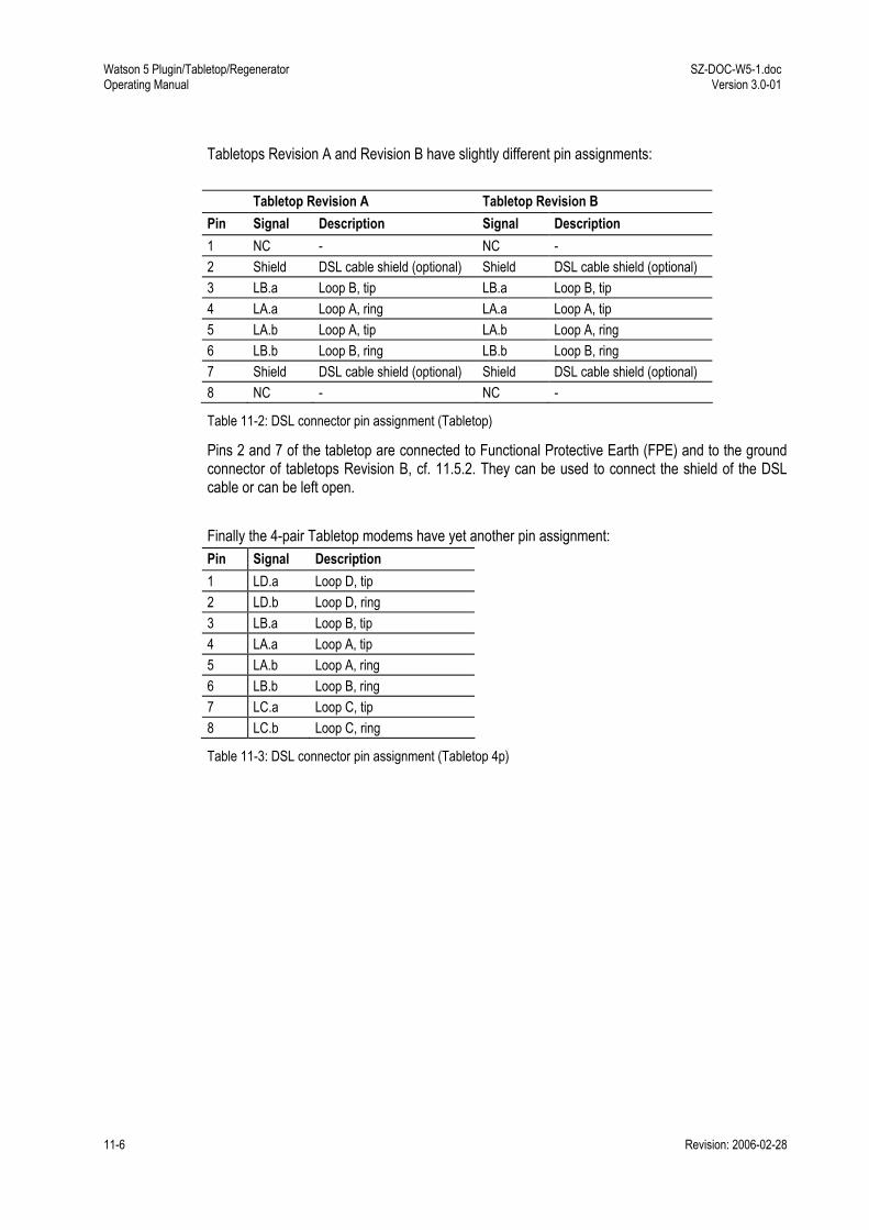
Watson 5 Plugin/Tabletop/Regenerator Operating Manual
SZ-DOC-W5-1.doc Version 3.0-01
11-6 Revision: 2006-02-28
Tabletops Revision A and Revision B have slightly different pin assignments: Tabletop Revision A Tabletop Revision B Pin Signal Description Signal Description 1 NC - NC - 2 Shield DSL cable shield (optional) Shield DSL cable shield (optional) 3 LB.a Loop B, tip LB.a Loop B, tip 4 LA.a Loop A, ring LA.a Loop A, tip 5 LA.b Loop A, tip LA.b Loop A, ring 6 LB.b Loop B, ring LB.b Loop B, ring 7 Shield DSL cable shield (optional) Shield DSL cable shield (optional) 8 NC - NC -
Table 11-2: DSL connector pin assignment (Tabletop)
Pins 2 and 7 of the tabletop are connected to Functional Protective Earth (FPE) and to the ground connector of tabletops Revision B, cf. 11.5.2. They can be used to connect the shield of the DSL cable or can be left open. Finally the 4-pair Tabletop modems have yet another pin assignment: Pin Signal Description 1 LD.a Loop D, tip 2 LD.b Loop D, ring 3 LB.a Loop B, tip 4 LA.a Loop A, tip 5 LA.b Loop A, ring 6 LB.b Loop B, ring 7 LC.a Loop C, tip 8 LC.b Loop C, ring
Table 11-3: DSL connector pin assignment (Tabletop 4p)

SZ-DOC-W5-1.doc Version 3.0-01
Watson 5 Plugin/Tabletop/Regenerator Operating Manual
Revision: 2006-02-28 11-7
11.1.2 DSL Cable SZ.378.0M0.V21: HDSL Cable, 4 pairs, 5m, open end
Figure 11-2: HDSL Cable, 4 pairs, 5m, open end

Watson 5 Plugin/Tabletop/Regenerator Operating Manual
SZ-DOC-W5-1.doc Version 3.0-01
11-8 Revision: 2006-02-28
11.2 E1 Interface
11.2.1 120 Ω Connectors on Plugin
2 x E1, 120 Ohm Type: SubD15 male (Front View)
1 8
9 15
Pin Signal Description 1 RX1a E1 120Ω Output 1 (wire A) 2 FPE-RX1 Functional Protective Earth (cable shield RX1) 3 TX1a E1 120Ω Input 1 (wire A) 4 FPE-TX1 Functional Protective Earth (cable shield TX1) 5 FPE-RX2 Functional Protective Earth (cable shield RX2) 6 RX2a E1 120Ω Output 2 (wire A) 7 FPE-TX2 Functional Protective Earth (cable shield TX2) 8 TX2a E1 120Ω Input 2 (wire A) 9 RX1b E1 120Ω Output 1 (wire B) 10 - Not Connected 11 TX1b E1 120Ω Input 1 (wire B) 12 - Not Connected 13 RX2b E1 120Ω Output 2 (wire B) 14 - Not Connected 15 TX2b E1 120Ω Input 2 (wire B)
Table 11-4: Pin Assignment Plugin E1 120 Ohm connector
Notes • On multiservice plugins with only E1 port 1 is available • Plugins with 4 x E1 have two connectors carrying E1 ports 1/2 and 3/4 respectively

SZ-DOC-W5-1.doc Version 3.0-01
Watson 5 Plugin/Tabletop/Regenerator Operating Manual
Revision: 2006-02-28 11-9
11.2.2 120 Ω Cable for Plugin SZ.378.0C0.V21: Cable 2 x E1, 10 m
Figure 11-3: Cable 2 x E1, 10 m
11.2.3 120 Ω Cable for Tabletop Revision A SZ.378.0C0.V1: Cable 1 x E1, 1.5 m
Figure 11-4: Cable 1 x E1, 1.5 m
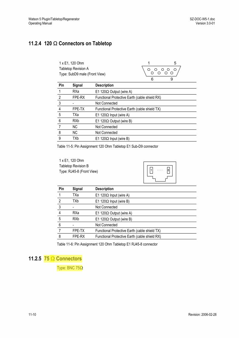
Watson 5 Plugin/Tabletop/Regenerator Operating Manual
SZ-DOC-W5-1.doc Version 3.0-01
11-10 Revision: 2006-02-28
11.2.4 120 Ω Connectors on Tabletop
1 x E1, 120 Ohm Tabletop Revision A Type: SubD9 male (Front View)
1 5
6 9 Pin Signal Description 1 RXa E1 120Ω Output (wire A) 2 FPE-RX Functional Protective Earth (cable shield RX) 3 - Not Connected 4 FPE-TX Functional Protective Earth (cable shield TX) 5 TXa E1 120Ω Input (wire A) 6 RXb E1 120Ω Output (wire B) 7 NC Not Connected 8 NC Not Connected 9 TXb E1 120Ω Input (wire B)
Table 11-5: Pin Assignment 120 Ohm Tabletop E1 Sub-D9 connector
1 x E1, 120 Ohm Tabletop Revision B Type: RJ45-8 (Front View)
1 8. . . .
Pin Signal Description 1 TXa E1 120Ω Input (wire A) 2 TXb E1 120Ω Input (wire B) 3 - Not Connected 4 RXa E1 120Ω Output (wire A) 5 RXb E1 120Ω Output (wire B) 6 - Not Connected 7 FPE-TX Functional Protective Earth (cable shield TX) 8 FPE-RX Functional Protective Earth (cable shield RX)
Table 11-6: Pin Assignment 120 Ohm Tabletop E1 RJ45-8 connector
11.2.5 75 Ω Connectors Type: BNC 75Ω
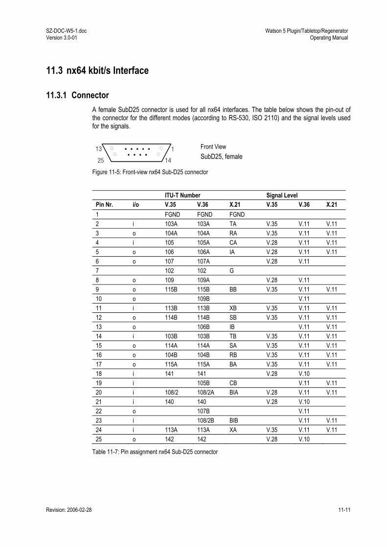
SZ-DOC-W5-1.doc Version 3.0-01
Watson 5 Plugin/Tabletop/Regenerator Operating Manual
Revision: 2006-02-28 11-11
11.3 nx64 kbit/s Interface
11.3.1 Connector A female SubD25 connector is used for all nx64 interfaces. The table below shows the pin-out of the connector for the different modes (according to RS-530, ISO 2110) and the signal levels used for the signals.
13 1
25 14
Front View SubD25, female
Figure 11-5: Front-view nx64 Sub-D25 connector
ITU-T Number Signal Level
Pin Nr. i/o V.35 V.36 X.21 V.35 V.36 X.21 1 FGND FGND FGND 2 i 103A 103A TA V.35 V.11 V.11 3 o 104A 104A RA V.35 V.11 V.11 4 i 105 105A CA V.28 V.11 V.11 5 o 106 106A IA V.28 V.11 V.11 6 o 107 107A V.28 V.11 7 102 102 G 8 o 109 109A V.28 V.11 9 o 115B 115B BB V.35 V.11 V.11 10 o 109B V.11 11 i 113B 113B XB V.35 V.11 V.11 12 o 114B 114B SB V.35 V.11 V.11 13 o 106B IB V.11 V.11 14 i 103B 103B TB V.35 V.11 V.11 15 o 114A 114A SA V.35 V.11 V.11 16 o 104B 104B RB V.35 V.11 V.11 17 o 115A 115A BA V.35 V.11 V.11 18 i 141 141 V.28 V.10 19 i 105B CB V.11 V.11 20 i 108/2 108/2A BIA V.28 V.11 V.11 21 i 140 140 V.28 V.10 22 o 107B V.11 23 i 108/2B BIB V.11 V.11 24 i 113A 113A XA V.35 V.11 V.11 25 o 142 142 V.28 V.10
Table 11-7: Pin assignment nx64 Sub-D25 connector
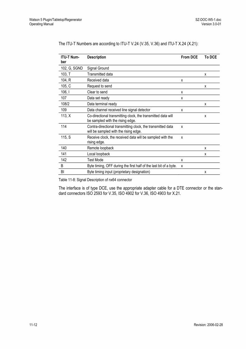
Watson 5 Plugin/Tabletop/Regenerator Operating Manual
SZ-DOC-W5-1.doc Version 3.0-01
11-12 Revision: 2006-02-28
The ITU-T Numbers are according to ITU-T V.24 (V.35, V.36) and ITU-T X.24 (X.21):
ITU-T Num-ber
Description From DCE To DCE
102, G, SGND Signal Ground 103, T Transmitted data x 104, R Received data x 105, C Request to send x 106, I Clear to send x 107 Data set ready x 108/2 Data terminal ready x 109 Data channel received line signal detector x 113, X Co-directional transmitting clock, the transmitted data will
be sampled with the rising edge. x
114 Contra-directional transmitting clock, the transmitted data will be sampled with the rising edge.
x
115, S Receive clock, the received data will be sampled with the rising edge.
x
140 Remote loopback x 141 Local loopback x 142 Test Mode x B Byte timing, OFF during the first half of the last bit of a byte. x BI Byte timing input (proprietary designation) x
Table 11-8: Signal Description of nx64 connector
The interface is of type DCE, use the appropriate adapter cable for a DTE connector or the stan-dard connectors ISO 2593 for V.35, ISO 4902 for V.36, ISO 4903 for X.21.

SZ-DOC-W5-1.doc Version 3.0-01
Watson 5 Plugin/Tabletop/Regenerator Operating Manual
Revision: 2006-02-28 11-13
11.3.2 V.35 DTE Cable SZ.378.0F1.V1: V.35 DTE Cable, 3m
Connector Type: 34 pin (ISO 2593), female ITU-T Number Pin Assignment 34 pin female (a/b) Pin Assignment 25 pin male (a/b) FGND A 1 SGND B 7 103 P/S 2/14 104 R/T 3/16 105 C 4 106 D 5 107 E 6 108 H 20 109 F 8 113 U/W 24/11 114 Y/AA 15/12 115 V/X 17/9 140 N 21 141 L 18 142 NN 25
V.35/ISO 259334 Pin Connectors
AA
A BC D
E FH
LN
P S R
T U
W Y X V
NN
C H
S W
A
E
P
U
D
N T X
B
L R V
NN
female male
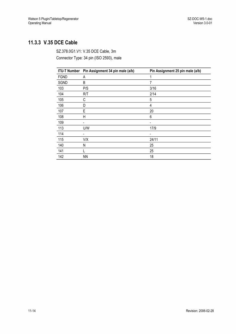
Watson 5 Plugin/Tabletop/Regenerator Operating Manual
SZ-DOC-W5-1.doc Version 3.0-01
11-14 Revision: 2006-02-28
11.3.3 V.35 DCE Cable SZ.378.0G1.V1: V.35 DCE Cable, 3m Connector Type: 34 pin (ISO 2593), male ITU-T Number Pin Assignment 34 pin male (a/b) Pin Assignment 25 pin male (a/b) FGND A 1 SGND B 7 103 P/S 3/16 104 R/T 2/14 105 C 5 106 D 4 107 E 20 108 H 6 109 - - 113 U/W 17/9 114 - - 115 V/X 24/11 140 N 25 141 L 25 142 NN 18
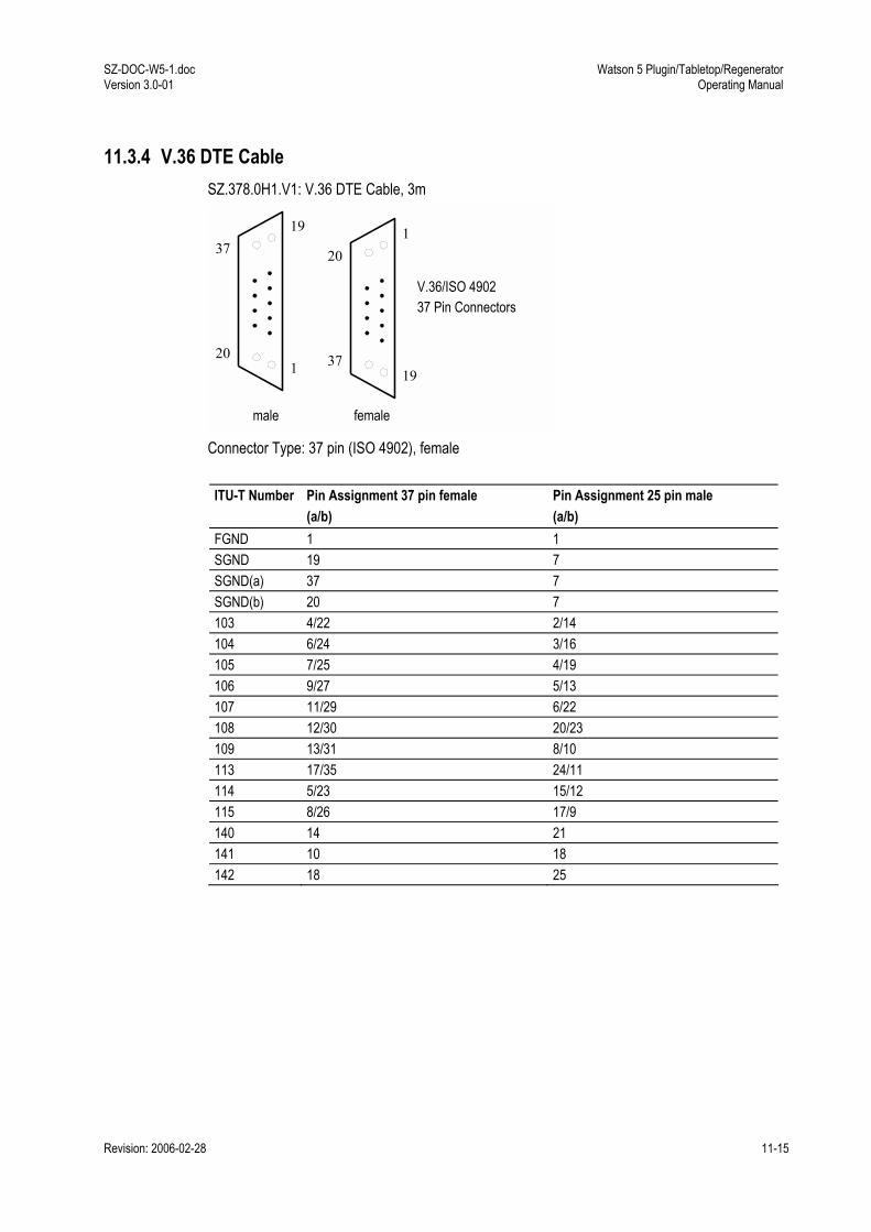
SZ-DOC-W5-1.doc Version 3.0-01
Watson 5 Plugin/Tabletop/Regenerator Operating Manual
Revision: 2006-02-28 11-15
11.3.4 V.36 DTE Cable SZ.378.0H1.V1: V.36 DTE Cable, 3m
Connector Type: 37 pin (ISO 4902), female ITU-T Number Pin Assignment 37 pin female
(a/b) Pin Assignment 25 pin male (a/b)
FGND 1 1 SGND 19 7 SGND(a) 37 7 SGND(b) 20 7 103 4/22 2/14 104 6/24 3/16 105 7/25 4/19 106 9/27 5/13 107 11/29 6/22 108 12/30 20/23 109 13/31 8/10 113 17/35 24/11 114 5/23 15/12 115 8/26 17/9 140 14 21 141 10 18 142 18 25
19
1
37
20
V.36/ISO 490237 Pin Connectors
femalemale
1
19
20
37

Watson 5 Plugin/Tabletop/Regenerator Operating Manual
SZ-DOC-W5-1.doc Version 3.0-01
11-16 Revision: 2006-02-28
11.3.5 V.36 DCE Cable SZ.378.0J1.V1: V.36 DCE Cable, 3m Connector Type: 37 pin (ISO 4902), male ITU-T Number Pin Assignment 37 pin male (a/b) Pin Assignment 25 pin male (a/b) FGND 1 1 SGND 19 7 SGND(a) 37 7 SGND(b) 20 7 103 4/22 3/16 104 6/24 2/14 105 7/25 5/13 106 9/27 4/19 107 11/29 20/23 108 12/30 6/22 109 - - 113 17/35 17/9 114 - - 115 8/26 24/11 140 14 25 141 10 25 142 18 18
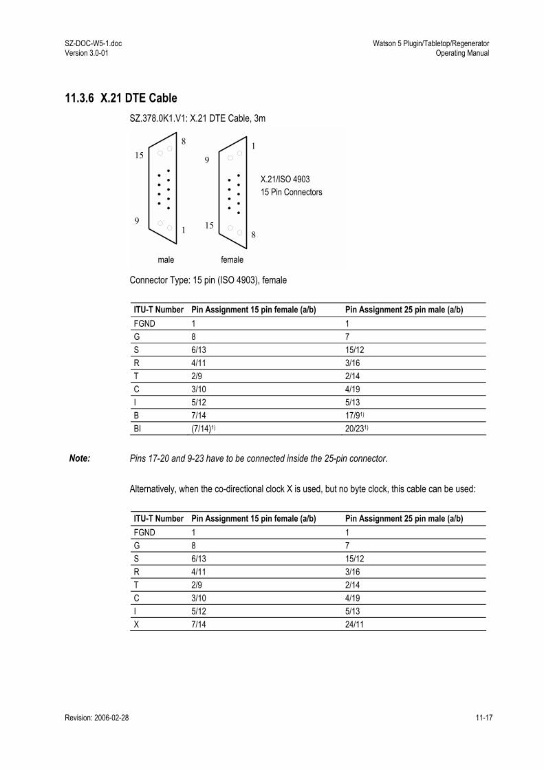
SZ-DOC-W5-1.doc Version 3.0-01
Watson 5 Plugin/Tabletop/Regenerator Operating Manual
Revision: 2006-02-28 11-17
11.3.6 X.21 DTE Cable SZ.378.0K1.V1: X.21 DTE Cable, 3m
Connector Type: 15 pin (ISO 4903), female ITU-T Number Pin Assignment 15 pin female (a/b) Pin Assignment 25 pin male (a/b) FGND 1 1 G 8 7 S 6/13 15/12 R 4/11 3/16 T 2/9 2/14 C 3/10 4/19 I 5/12 5/13 B 7/14 17/91) BI (7/14)1) 20/231)
Note: Pins 17-20 and 9-23 have to be connected inside the 25-pin connector.
Alternatively, when the co-directional clock X is used, but no byte clock, this cable can be used: ITU-T Number Pin Assignment 15 pin female (a/b) Pin Assignment 25 pin male (a/b) FGND 1 1 G 8 7 S 6/13 15/12 R 4/11 3/16 T 2/9 2/14 C 3/10 4/19 I 5/12 5/13 X 7/14 24/11
8
1
15
9
X.21/ISO 490315 Pin Connectors
femalemale
19
15 8

Watson 5 Plugin/Tabletop/Regenerator Operating Manual
SZ-DOC-W5-1.doc Version 3.0-01
11-18 Revision: 2006-02-28
11.3.7 X.21 DCE Cable SZ.378.0L1.V1: X.21 DCE Cable, 3m Connector Type: 15 pin (ISO 4903), male ITU-T Number Pin Assignment 15 pin male (a/b) Pin Assignment 25 pin male (a/b) FGND 1 1 G 8 7 S 6/13 24/11 R 4/11 2/14 T 2/9 3/16 C 3/10 5/13 I 5/12 4/19 B 7/14 20/23
Alternatively, when the co-directional clock X is used, but no byte clock, this cable can be used: ITU-T Number Pin Assignment 15 pin female (a/b) Pin Assignment 25 pin male (a/b) FGND 1 1 G 8 7 S 6/13 24/11 R 4/11 2/14 T 2/9 3/16 C 3/10 5/13 I 5/12 4/19 X 7/14 15/12
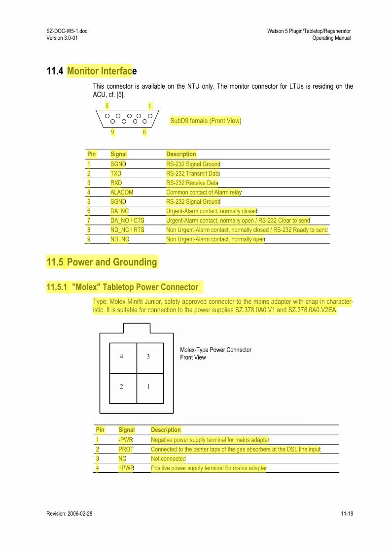
SZ-DOC-W5-1.doc Version 3.0-01
Watson 5 Plugin/Tabletop/Regenerator Operating Manual
Revision: 2006-02-28 11-19
11.4 Monitor Interface This connector is available on the NTU only. The monitor connector for LTUs is residing on the ACU, cf. [5].
SubD9 female (Front View)
Pin Signal Description 1 SGND RS-232 Signal Ground 2 TXD RS-232 Transmit Data 3 RXD RS-232 Receive Data 4 ALACOM Common contact of Alarm relay 5 SGND RS-232 Signal Ground 6 DA_NC Urgent-Alarm contact, normally closed 7 DA_NO / CTS Urgent-Alarm contact, normally open / RS-232 Clear to send 8 ND_NC / RTS Non Urgent-Alarm contact, normally closed / RS-232 Ready to send9 ND_NO Non Urgent-Alarm contact, normally open
11.5 Power and Grounding
11.5.1 "Molex" Tabletop Power Connector Type: Molex Minifit Junior, safety approved connector to the mains adapter with snap-in character-istic. It is suitable for connection to the power supplies SZ.378.0A0.V1 and SZ.378.0A0.V2EA.
Pin Signal Description 1 -PWR Negative power supply terminal for mains adapter 2 PROT Connected to the center taps of the gas absorbers at the DSL line input 3 NC Not connected 4 +PWR Positive power supply terminal for mains adapter
5 1
9 6
Molex-Type Power Connector Front View 4 3
2 1

Watson 5 Plugin/Tabletop/Regenerator Operating Manual
SZ-DOC-W5-1.doc Version 3.0-01
11-20 Revision: 2006-02-28
11.5.2 Ground connector Tabletops Revision B are fitted with a ground connector (FPE, Functional Protective Earth).The connector is normally covered by the rear panel of the housing. To get access to the connector a hole has to be cut in the rear panel around the indicated marks e.g. using a paper cutter.:
Ground Connector covered
Cutout hole removed
The connector type is Faston 4.8 x 0.5 mm connector (DIN 46244) The hole in the rear panel is di-mensioned for non-insulated Faston ferrules (DIN 46245).
11.6 Regenerator The regenerator has one DIN-C/2 type male connector: 216
c
a
Pin No. Signal Name Pin No Signal Name 2a Tip REG C, Loop B 2c Ring REG C, Loop B 4a Tip REG C, Loop A 4c Ring REG C, Loop A 6a n.c. 6c n.c. 8a Local Power positive 8c Local Power positive 10a Local Power negative 10c Local Power negative 12a n.c. 12c n.c. 14a Tip REG R, Loop B 14c Ring REG R, Loop B 16a Tip REG R, Loop A 16c Ring REG R, Loop A n.c. = not connected

SZ-DOC-W5-1.doc Version 3.0-01
Watson 5 Plugin/Tabletop/Regenerator Operating Manual
Revision: 2006-02-28 12-21
12 Technical Specifications
12.1 Interfaces
12.1.1 DSL Line Interface
Standard referred: ETSI TS 101 524, ITU-T G.991.2 Annex B Number of Pairs: 1, 2 or 4 Line Rate per Pair: 200-2320kbit/s ± 32ppm Line Code: Trellis-coded PAM16 Nominal Line Impedance: 135Ω Transmit Power @ 135Ω: According to TS 101 524 Remote Powering (Revision A) Asymmetric 117 VDC max
Current limit 59 mA max Remote Powering (Revision B) Symmetric 117 VDC max
Current limit 59 mA max Fault current to earth 2 mA max
Overvoltage Protection: LTU: ITU-T K.20: 2000 (K.44: 2000) NTU: ITU-T K.21: 2000 (K.44: 2000) Regenerator: ITU-T K.21, ITU-T K.45
Connector Type: RJ-45, 8 pin

Watson 5 Plugin/Tabletop/Regenerator Operating Manual
SZ-DOC-W5-1.doc Version 3.0-01
12-22 Revision: 2006-02-28
12.1.2 User Interfaces E1: Standard referred: ITU-T G.703 / G.704 Bitrate: 2048kbit/s ± 50ppm Line Code: HDB3 Framing: ITU-T G.704 / transparent Input Impedance: 120Ω
75Ω Signal Amplitude: ± 3.00V @ 120Ω
± 2.37V @ 75Ω Jitter Performance: According to ITU-T G.823 ESD - Protection: 8kV (Air discharge) Connector Type: Plugin: SubD15 male 120Ω or BNC 75Ω
Tabletop Revision A: SubD9 female 120Ω or BNC 75Ω Tabletop Revision B: RJ45-8 120Ω or BNC 75Ω
PRA: Standard referred: ETS 300 233, ETS 300 011, ETS 300 046
nx64 kbit/s: V.35 V.36 X.21 Bitrate: nx64 kbit/s (n=0..72), (n=0..96, in 3p and 4p mode) Signal Levels: Data Lines: Clock Lines: Control Lines:
ITU-T V.35 ITU-T V.35 ITU-T V.28
ITU-T V.11 ITU-T V.11 ITU-T V.11/V.10
ITU-T V.11 ITU-T V.11 ITU-T V.11
ESD-Protection: 8kV (Air discharge) Connector Type HDSL: SubD25 (ISO 2110),
female SubD25 (RS 530), female
SubD25 female
Connector Type Cable: 34 pin (ISO 2593) 37 pin (ISO 4902) 15 pin (ISO 4903)
12.1.3 Monitor Interface Signal Level: RS-232 Data Rate: 9600 Baud, Asynchronous Protocol: 8 Bit, No Parity, 1 Stop Bit
No Linefeed with Carriage Return XON/XOFF enabled
Connector Type: SubD9 female

SZ-DOC-W5-1.doc Version 3.0-01
Watson 5 Plugin/Tabletop/Regenerator Operating Manual
Revision: 2006-02-28 12-23
12.2 Power Consumption
12.2.1 Plugin Supply Voltage: -40.5VDC .. -72VDC
Power consumption depends on the combination of DSL ports and user interfaces on the plugin card: Interfaces Order Codes Power Consumption
[W] 1 x E1, 1 x nx64, 1 x DSL SZ.866.V318
SZ.866.V338 5.0
1 x E1, 1 x nx64, 2 x DSL SZ.866.V418 SZ.866.V438
7.5
2 x E1, 2 x DSL SZ.866.V511 SZ.866.V533
5.4
2 x nx64, 2 x DSL SZ.866.V588 6.0 2 x E1, 4 x DSL SZ.866.V611
SZ.866.V633 SZ.866.V711 SZ.866.V733
8.5
2 x nx64, 4 x DSL SZ.866.V788 9.1 4 x E1, 4 x DSL SZ.866.V614
SZ.866.V634 SZ.896.V614 SZ.896.V634
10.0
1 x E1, 4 x DSL SZ.866.V810 SZ.866.V830
8.5
1 x nx64, 4 x DSL SZ.866.V880 9.1
Notes: • The power consumptions given above are measured with the highest possible linerate (2'312 kbps per pair) for nx64 and multiservice modems. Power consumption for SZ.866.V614, SZ.866.V634, SZ.896.V614 and SZ.896.V634 is measured with 2'056 kbps per pair. E1 4-pair modems (SZ.866.V810 and SZ.866.V830) are measured with a linerate of 520 kbps per pair. Power consumption decreases with decreasing linerate.
• If remote powering is used then the power consumption is increased by 6.1 W per powered pair
• Watson 5 LTUs must be used with the subrack SZ.379.V3WD or higher which has a 16A fuse

Watson 5 Plugin/Tabletop/Regenerator Operating Manual
SZ-DOC-W5-1.doc Version 3.0-01
12-24 Revision: 2006-02-28
12.2.2 Tabletop Local Power Supply Remote Power Supply Supply Voltage -40.5VDC .. -72VDC -112VDC .. -65VDC at NTU DSL-
Connector Power consumption depends on the combination of DSL ports and user interfaces: Interfaces Order Codes Power Consumption
[W] 1 x E1, 1 x DSL, Revision A SZ.886.V310
SZ.886.V330 3.7
1 x E1, 1 x DSL, Revision B SZ:846.V310 SZ.846.V330
2.7
1 x nx64, 1 x DSL, Revision A SZ.886.V380 4.8 1 x nx64, 1 x DSL, Revision B SZ.846.V380 3.0 1 x E1, 1 x nx64, 1 x DSL, Revision A SZ.886.V318
SZ.886.V338 5.1
1 x E1, 1 x nx64, 1 x DSL, Revision B SZ.846.V318 SZ.846.V338
3.2
1 x E1, 2 x DSL, Revision A SZ.886.V410 SZ.886.V430
4.9
1 x E1, 2 x DSL, Revision B SZ.846.V410 SZ.846.V430
3.8
1 x E1, 1 x nx64, 2 x DSL, Revision A SZ.886.V418 SZ.886.V438
6.3
1 x E1, 1 x nx64, 2 x DSL, Revision B SZ.846.V418 SZ.846.V438
4.4
1 x nx64, 2 x DSL, Revision A SZ.886.V480 6.0 1 x nx64, 2 x DSL, Revision B SZ.846.V480 4.2 1 x E1, 4 x DSL, Revision A SZ.886.V810
SZ.886.V830 6.2
1 x nx64, 4 x DSL, Revision A SZ.886.V880 10.4
12.2.3 Regenerator Local power supply 60 VDC .. 115 VDC , 5W Power consumption, one-pair operation 2.3 W Power consumption, two-pair operation 3.5 W
12.3 MTBF Values Plugin E1 Revision A 50 years Plugin nx64 Revision A 46 years Tabletop E1 Revision A 42 years Tabletop nx64 Revision A 40 years

SZ-DOC-W5-1.doc Version 3.0-01
Watson 5 Plugin/Tabletop/Regenerator Operating Manual
Revision: 2006-02-28 12-25
12.4 Environment
12.4.1 Climatic Conditions (Plugin and Tabletop) Storage: ETS 300 019-1-1 Class 1.2 -25°C +55°C, 10% .. 100% RH Transportation: ETS 300 019-1-2 Class 2.3 -40°C +70°C, max. 95% RH Operation: ETS 300 019-1-3 Class 3.2e -5°C +60°C, 5% .. 95% RH
12.4.2 Climatic Conditions (Regenerator) Storage: ETS 300 019-1-1 Class 1.2 -25°C +55°C, 10% .. 100% RH Transportation: ETS 300 019-1-2 Class 2.3 -40°C +70°C, max. 95% RH Operation: ETS 300 019-1-3 Class 4.1e -33°C +70°C, 10% .. 100% RH
12.4.3 Safety According to EN 60950:2000 (IEC60950:1999)
12.4.4 EMC According to EN 300386:2000
12.5 Physical dimensions and weight
12.5.1 Plugin 19 Plugin unit: height: 259mm (6 HE), width: 30mm PCB dimensions: height: 233.35mm, length: 220mm Weight 500g
12.5.2 Tabletop Tabletop unit: width 220mm, depth 195mm, height 43mm Weight 750g
12.5.3 Regenerator Width 105 mm, depth 154 mm, height 27 mm Weight 350g


![W5 abdomen[1]](https://img.pdfslide.us/doc/110x75/577d2e9e1a28ab4e1eaf8a9e/w5-abdomen1.jpg)