Embed Size (px)
Citation preview

232857
Woodstock Technical Support .................. 2Controls and Features ........................... 3Model W1819 Specifications .................... 4Model W1820 Specifications .................... 7
Standard Machinery Safety ................... 10Additional Safety for Table Saws ............ 12Preventing Kickback ........................... 13Protecting Yourself From Kickback .......... 13Glossary of Terms .............................. 14
Availability ...................................... 15Full-Load Current Rating ...................... 15Circuit Requirements .......................... 15Grounding Instructions ........................ 16Extension Cords ................................ 16
Unpacking ....................................... 17Items Needed for Setup ....................... 17Inventory ........................................ 18Fence Inventory W1819 ....................... 19Fence Inventory W1820 ....................... 20Machine Placement ............................ 21Cleaning Machine ............................... 21Assembly ......................................... 22Dust Collection ................................. 29Test Run .......................................... 30
General .......................................... 31Basic Controls ................................... 31Non-Through & Through Cuts ................ 32Blade Selection ................................. 33Blade Installation .............................. 35Blade Guard Assembly ......................... 36Riving Knife ..................................... 38Workpiece Inspection .......................... 39Ripping ........................................... 40Crosscutting ..................................... 41Miter Cuts ....................................... 42Blade Tilt & Bevel Cuts........................ 42Dado Cutting .................................... 43Rabbet Cutting ................................. 46Resawing ......................................... 48Table Saw Accessories ......................... 52
Featherboards .................................. 54Push Sticks ...................................... 57Push Blocks ...................................... 58Narrow-Rip Auxiliary Fence & Push Block .. 59Outfeed & Support Tables .................... 61Crosscut Sled .................................... 61
Schedule ......................................... 62Cleaning ......................................... 62Lubrication ...................................... 63
General .......................................... 64Blade Tilt Stops ................................. 64Miter Slot to Blade Parallelism ............... 66Spreader or Riving Knife Alignment ......... 67Fence Adjustments ............................. 69Fence Scale Calibration ....................... 71Miter Gauge Adjustments ..................... 72Belt Tension & Replacement ................. 73Electrical Safety Instructions ................. 74Model W1819/W1820 Wiring Diagram ....... 75Troubleshooting ................................. 76
Body .............................................. 78Trunnion ......................................... 80Blade Guard ..................................... 83Miter Gauge ..................................... 84Fence ............................................. 85W1819 Extension Wing & Rails ............... 86W1820 Extension Wing & Rails ............... 87Machine Labels ................................. 88

-2-
This machine has been specially designed to provide many years of trouble-free service. Close attention to detail, ruggedly built parts and a rigid quality control program assure safe and reliable operation.
Woodstock International, Inc. is committed to customer satisfaction. Our intent with this manual is to include the basic information for safety, setup, operation, maintenance, and service of this product.
We stand behind our machines! In the event that questions arise about your machine, please contact Woodstock International Technical Support at (360) 734-3482 or send e-mail to:
. Our knowledgeable staff will help you troubleshoot problems and process warranty claims.
If you need the latest edition of this manual, you can download it from . If you have comments about this manual, please contact us at:
-3-
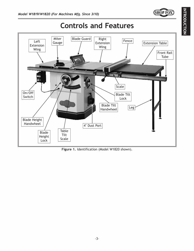
Identification (Model W1820 shown).
Front Rail Tube
FenceExtension Table
Blade Height Lock
Blade Height Handwheel
Miter Gauge
Blade Tilt Lock
Blade Guard
Scale
Left Extension
Wing
Right Extension
Wing
On/Off Switch
LegBlade Tilt
Handwheel
Table Tilt
Scale
4" Dust Port

-4-
Phone #: (360) 734-3482 • Online Tech Support: [email protected] • Web: www.shopfox.biz
Type ...................................................................................TEFC Capacitor Start InductionHorsepower .......................................................................................................... 3 HPVoltage ................................................................................................................230VPhase ................................................................................................................ SingleAmps ................................................................................................................. 12.8ASpeed ............................................................................................................ 3450 RPMCycle ................................................................................................................. 60 HzNumber Of Speeds ...................................................................................................... 1Power Transfer ...................................................................................... Triple V-Belt DriveBearings ............................................................................ Shielded and Permanently Sealed
Maximum Blade Diameter ............................................................................................ 10" Riving Knife/Spreader Thickness ........................................................................0.1" (2.5mm)Required Blade Body Thickness ........................................................ 0.071"-0.094" (1.8-2.4mm)Required Blade Kerf Thickness ......................................................... 0.102"-0.126" (2.6-3.2mm)Maximum Width of Dado ........................................................................................... 13⁄16"Blade Tilt .......................................................................................................Left 0-45ºArbor Size ..............................................................................................................5⁄8"Arbor Speed .................................................................................................... 4300 RPMArbor Bearings ................................................................. Sealed and Permanently Lubricated
Maximum Depth of Cut at 90 Degrees ........................................................................... 31⁄8"Maximum Depth of Cut at 45 Degrees .......................................................................... 23⁄16"Maximum Rip to Right of Blade-Standard ......................................................................... 29"Maximum Rip to Left of Blade ................................................................................... 131⁄2"
Fully Assembled Table Length .................................................................................... 535⁄8"Table Depth ............................................................................................................ 27"Table Thickness ...................................................................................................... 17⁄8"Floor to Table Height ................................................................................................. 34"Distance Front of Table to Center of Blade .................................................................... 171⁄8"Distance Front of Table to Blade at Maximum Cut ........................................................... 121⁄2"

-5-
Fence Type .............................................................. Camlock T-Shaped Fence with HDPE FaceFence Size Length ................................................................................................. 395⁄16"Fence Size Width .................................................................................................... 37⁄8"Fence Size Height ................................................................................................... 21⁄2"Fence Rail Type ....................................................................................Square Steel TubingFence Rail Length ..................................................................................................... 62"Fence Rail Width .................................................................................................... 23⁄4"Fence Rail Height ...................................................................................................... 2"
Miter Gauge Slot Type .............................................................................................T-SlotMiter Gauge Slot Size Width .........................................................................................3⁄4" Miter Gauge Slot Size Height ........................................................................................3⁄8"
Weight .................................................................................................................. 550 lbs.Length ......................................................................................................................... 62"Width ....................................................................................................................... 451⁄2"Height ......................................................................................................................... 40"Foot Print (Length/Width) ........................................................................................ 221⁄4" x 20"
Table Construction .............................................................................. Precision Ground Cast IronWings Construction ............................................................................. Precision Ground Cast Iron Extension Table ....................................................................................................... Phenolic Trunnions Construction ..............................................................................................Cast IronBase Construction.......................................................................................... Pre-Formed SteelBody Assembly Construction ............................................................................. Pre-Formed SteelFence Assembly Construction ................................................................Steel with HDPE Side PlatesRails Construction .........................................................................................................SteelMiter Gauge Construction .........................................................................Cast Iron with Steel BarGuard Construction ......................................................................................... Steel and PlasticPaint ............................................................................................................ Powder Coated
Type ............................................................................................. Cardboard/Wood SkidsContent ................................................................................. Machine and Table ExtensionWeight............................................................................................................. 460 lbs.Length/Width/Height ................................................................................... 24" x 30" x 43"
Type ............................................................................................................ CardboardContent ............................................................................................................. FenceWeight...............................................................................................................24 lbs.Length/Width/Height .....................................................................................42" x 17" x 7"
Type ............................................................................................................ CardboardContent ............................................................................................................... RailsWeight...............................................................................................................44 lbs.Length/Width/Height ...................................................................................... 66" x 7" x 5"

-6-
Power Requirement........................................................................220V-240V, Single-Phase, 60 HzSwitch ....................................................................... Magnetic with Thermal Overload ProtectionSwitch Voltage .............................................................................................................220VCord Length ................................................................................................................. 6 ft.Cord Gauge ............................................................................................................14 gaugeRecommended Circuit Size ................................................................................................ 20APlug Included .................................................................................................................YesIncluded Plug Type ........................................................................................................ 6-20
Number of Dust Ports ........................................................................................................ 1Dust Port Size ................................................................................................................. 4"ISO Factory ............................................................................................................ ISO 9001Warranty ................................................................................................................. 2 YearsCountry of Origin ......................................................................................................... ChinaSerial Number Location .................................................................................ID Label on CabinetCustomer Setup and Cleaning Time ...................................................................................1 Hour
Leeson motorPrecision ground cast iron tableCast iron trunnions4" dust portRiving knife and blade guardPowder coated paintStandard and dado table insertsQuick release riving knifeQuick release motor guardQuick release splitter assemblyEasy glide fence systemQuick-release device for changing guard/riving knifeKnurled knobs for adjusting fenceNylon runners inside fence head assemblyT-square type fence systemT-slot miter gauge with extruded aluminum fence and flip stopCamlock T-shaped fence with HDPE faceRecessed screw holding table insertDevice on blade guard allows enabling or disabling of anti-kickback pawls

-7-
Phone #: (360) 734-3482 • Online Tech Support: [email protected] • Web: www.shopfox.biz
Type ...................................................................................TEFC Capacitor Start InductionHorsepower .......................................................................................................... 3 HPVoltage ................................................................................................................230VPhase ................................................................................................................ SingleAmps ................................................................................................................. 12.8ASpeed ............................................................................................................ 3450 RPMCycle ................................................................................................................. 60 HzNumber Of Speeds ...................................................................................................... 1Power Transfer ...................................................................................... Triple V-Belt DriveBearings ............................................................................ Shielded and Permanently Sealed
Maximum Blade Diameter ............................................................................................ 10" Riving Knife/Spreader Thickness ........................................................................0.1" (2.5mm)Required Blade Body Thickness ........................................................ 0.071"-0.094" (1.8-2.4mm)Required Blade Kerf Thickness ......................................................... 0.102"-0.126" (2.6-3.2mm)Maximum Width of Dado ........................................................................................... 13⁄16"Blade Tilt .......................................................................................................Left 0-45ºArbor Size ..............................................................................................................5⁄8"Arbor Speed .................................................................................................... 4300 RPMArbor Bearings ................................................................. Sealed and Permanently Lubricated
Maximum Depth of Cut at 90 Degrees ........................................................................... 31⁄8"Maximum Depth of Cut at 45 Degrees .......................................................................... 23⁄16"Maximum Rip to Right of Blade-Standard ......................................................................... 49"Maximum Rip to Left of Blade ................................................................................... 131⁄2"
Fully Assembled Table Length ....................................................................................... 72"Table Depth ............................................................................................................ 27"Table Thickness ...................................................................................................... 17⁄8"Floor to Table Height ................................................................................................. 34"Distance Front of Table to Center of Blade .................................................................... 171⁄8"Distance Front of Table to Blade at Maximum Cut ........................................................... 121⁄2"

-8-
Fence Type .............................................................. Camlock T-Shaped Fence with HDPE FaceFence Size Length ................................................................................................. 395⁄16"Fence Size Width .................................................................................................... 37⁄8"Fence Size Height ................................................................................................... 21⁄2"Fence Rail Type ....................................................................................Square Steel TubingFence Rail Length ..................................................................................................... 82"Fence Rail Width .................................................................................................... 23⁄4"Fence Rail Height ...................................................................................................... 2"
Miter Gauge Slot Type .............................................................................................T-SlotMiter Gauge Slot Size Width .........................................................................................3⁄4" Miter Gauge Slot Size Height ........................................................................................3⁄8"
Weight .................................................................................................................. 590 lbs.Length ......................................................................................................................... 82"Width ....................................................................................................................... 451⁄2"Height ......................................................................................................................... 40"Foot Print (Length/Width) ........................................................................................ 221⁄4" x 20"
Table Construction .............................................................................. Precision Ground Cast IronWings Construction ............................................................................. Precision Ground Cast Iron Extension Table ....................................................................................................... Phenolic Trunnions Construction ..............................................................................................Cast IronBase Construction.......................................................................................... Pre-Formed SteelBody Assembly Construction ............................................................................. Pre-Formed SteelFence Assembly Construction ................................................................Steel with HDPE Side PlatesRails Construction .........................................................................................................SteelMiter Gauge Construction .........................................................................Cast Iron with Steel BarGuard Construction ......................................................................................... Steel and PlasticPaint ............................................................................................................ Powder Coated
Type ............................................................................................. Cardboard/Wood SkidsContent ................................................................................. Machine and Table ExtensionWeight............................................................................................................. 476 lbs.Length/Width/Height ................................................................................... 33" x 30" x 40"
Type ............................................................................................................ CardboardContent ............................................................................................................. FenceWeight...............................................................................................................26 lbs.Length/Width/Height .....................................................................................42" x 17" x 7"
Type ............................................................................................................ CardboardContent ............................................................................................................... RailsWeight...............................................................................................................66 lbs.Length/Width/Height ...................................................................................... 91" x 7" x 5"

-9-
Power Requirement........................................................................220V-240V, Single-Phase, 60 HzSwitch ....................................................................... Magnetic with Thermal Overload ProtectionSwitch Voltage .............................................................................................................220VCord Length ................................................................................................................. 6 ft.Cord Gauge ............................................................................................................14 gaugeRecommended Circuit Size ................................................................................................ 20APlug Included .................................................................................................................YesIncluded Plug Type ........................................................................................................ 6-20
Number of Dust Ports ........................................................................................................ 1Dust Port Size ................................................................................................................. 4"ISO Factory ............................................................................................................ ISO 9001Warranty ................................................................................................................. 2 YearsCountry of Origin ......................................................................................................... ChinaSerial Number Location .................................................................................ID Label on CabinetCustomer Setup and Cleaning Time ...................................................................................1 Hour
Leeson MotorPrecision ground cast iron tableCast iron trunnions4" dust portRiving knife and blade guardPowder coated paintStandard and dado table insertsQuick release riving knifeQuick release motor guardQuick release splitter assemblyEasy glide fence systemQuick-release device for changing guard/riving knifeKnurled knobs for adjusting fenceNylon runners inside fence head assemblyT-square type fence systemT-slot miter gauge with extruded aluminum fence and flip stopCamlock T-shaped fence with HDPE faceRecessed screw holding table insertDevice on blade guard allows enabling or disabling of anti-kickback pawls

-10-

-11-
-12-
Touching a spinning saw blade will cause serious laceration or amputation injuries. Never purposely touch a saw blade during operation, and always keep hands/fingers away from blade path and moving blade.
Operating saw with the blade guard removed greatly increases the risk of severe laceration or amputation injuries from accidental blade contact. Keep the blade guard installed for all “through cuts” and immediately replace it if removed.
Not using the riving knife when making non-through cuts with a standard blade will increase the risk of kickback or accidental blade contact. Always use the riving knife whenever required.
. A workpiece ejected from the saw during operation (kickback) can cause severe impact injury to the operator or bystanders. To reduce the risk of this hazard, you must have an understand-ing of what causes of kickback and how to prevent it.
. Reaching behind the saw blade while cutting greatly increases the risk of amputation if a kickback occurs. Never reach behind or over the blade while cutting.
. Poor workpiece control significantly increases the risk of a kickback or accidental blade contact while cutting. Always use a properly setup guide, such as a fence or miter gauge, when cutting; and keep the workpiece firmly against the table and the guide until the workpiece is clear of the blade. DO NOT attempt to make any cuts "free hand" (without a guide).
. Standing in the blade path (directly in front of blade) while cutting, increases your risk of being hit by the workpiece if a kickback occurs. Stand to the side of the blade path to minimize this risk.
Removing cut-off pieces while the saw is running increases the risk of blade contact. Never use your hands to move cut-offs away from the blade. If a cut-off becomes trapped between the blade and table insert, turn the saw and allow the blade to stop before removing it.
. Adjusting the blade height or tilt during operation increases the risk of crash-ing the blade and sending metal fragments flying with deadly force at the operator or bystanders. Only adjust the blade height and tilt with the saw .
. Using safety devices such as push sticks, featherboards, or hold-downs can greatly reduce the risk of serious personal injury when using a table saw. Use safety devices whenever pos-sible.
. Changing blades while the saw is connected to power greatly increases the risk of injury if the saw is accidentally powered up. Always disconnect power to the saw before changing blades.
. Using a damaged blade creates the risk of broken blade pieces ejecting and hitting the operator. Never use blades that have been dropped or otherwise damaged.
DADO AND RABBET OPERATIONS. Dado and rabbeting operations require special attention because those operations must be performed with the blade guard removed. DO NOT attempt these operations without first reading the sections in this manual on those specific operations.
-13-
Below are ways to avoid the most common causes of kickback:
• Only cut workpieces with at least one smooth and straight edge. DO NOT cut warped, cupped or twisted wood.
• Never attempt freehand cuts. If the workpiece is not fed parallel with the blade, kickback will likely occur. Always use the rip fence or miter gauge to support the workpiece.
• Make sure the spreader or riving knife is aligned with the blade. A misaligned spreader or riving knife can cause the workpiece to catch or bind, increasing the chance of kickback. If you think that your spreader or riving knife is not aligned with the blade, check it immediately!
• Take the time to check and adjust the rip fence parallel with the blade; otherwise, the chances of kickback are extreme.
• The spreader or riving knife maintains the kerf in the workpiece, reducing the chance of kickback. Always use the riving knife for all non-through operations, unless a dado blade is installed. Always use the spreader with the blade guard for all through cuts.
• Feed cuts through to completion. Anytime you stop feeding a workpiece in the middle of a cut, the chance of kickback is greatly increased.
• Keep the blade guard installed and in good working order. Only remove it when per-forming non-through cuts and immediately re-install the blade guard when finished. Remember, always use the riving knife for all non-through operations, unless a dado blade is installed.
• Make multiple, shallow passes when per-forming a non-through cut. Making a deep non-through cut will greatly increase the chance of kickback.
Even if you know how to prevent kickback, it may still happen. Here are some ways to protect yourself if kickback DOES occur:
• Stand to the side of the blade during every cut. If kickback does occur, the thrown workpiece usually travels directly in front of the blade.
• Wear safety glasses or a face shield. In the event of kickback, your eyes and face are the most vulnerable part of your body.
• Never, for any reason, place your hand behind the blade. Should kickback occur, your hand may be pulled into the blade, which could cause amputation.
• Use a push stick to keep your hands farther away from the moving blade. If kickback occurs, the push stick will most likely take the damage that your hand would have received.
• Use featherboards or anti-kickback devices to prevent or slow down kickback.
-14-
The following is a list of common definitions, terms and phrases used throughout this manual as they relate to this table saw and woodworking in general. Become familiar with these terms for assembling, adjusting or operating this machine.
A metal shaft extending from the drive mechanism that is the mounting location for the saw blade.
A cut made with the blade tilted to an angle between 0˚ and 45˚ to cut a beveled edge onto a workpiece. Refer to for more details.
Metal or plastic safety device that mounts over the saw blade. Its function is to prevent the operator from com-ing into contact with the saw blade. Refer to
for more details.
Cutting operation in which the crosscut fence is used to cut across the shortest width of the workpiece. Refer to for more details.
Blade or set of blades that are used to cut grooves and rabbets. Refer to for more details.
The saw and arbor are not intended to safely use a larger dado blade.
Cutting operation that uses a dado blade to cut a flat bottomed groove into the face of the workpiece. Refer to for more details.
Safety device used to keep the workpiece against the rip fence and against the table surface. Refer to for more details.
The resulting cut or gap in the workpiece after the saw blade passes through during a cutting operation.
An event in which the workpiece is propelled back towards the operator at a high rate of speed.
A cut in which the blade does not cut through the top of the workpiece. Refer to for more details.
Being an equal distance apart at every point along two given lines or planes (i.e. the rip fence face is parallel to the face of the saw blade).
Lines or planes that intersect and form right angles (i.e. the blade is perpendicu-lar to the table surface).
Safety device used to push the workpiece through a cutting operation. Used most often when rip cutting thin workpieces. Refer to for more details.
Cutting operation that creates an L-shaped channel along the edge of the workpiece. Refer to for more details.
Cutting operation in which the rip fence is used to cut across the widest width of the workpiece. Refer to for more details.
Metal plate located behind the blade. It maintains the kerf opening in the wood when performing a cutting operation. Refer to for more details.
A tool used to check the flatness, parallelism, or consistency of a surface(s).
A blade with a kerf or thickness that is thinner than a standard blade cannot be used on this saw.
A cut in which the blade cuts com-pletely through the workpiece. Refer to
for more details.
-15-
Before installing the machine, consider the availability and proximity of the required power supply circuit. If an existing circuit does not meet the requirements for this machine, a new circuit must be installed. To minimize the risk of electrocution, fire, or equipment damage, installation work and electrical wiring must be done by a qualified electrician in accordance with all applicable codes and standards.
The full-load current rating is the amperage a machine draws at 100% of the rated output power. On machines with multiple motors, this is the amperage drawn by the largest motor or sum of all motors and electrical devices that might operate at one time during normal operations.
The full-load current is not the maximum amount of amps that the machine will draw. If the machine is overloaded, it will draw additional amps beyond the full-load rating.
If the machine is overloaded for a sufficient length of time, damage, overheating, or fire may result—especially if connected to an undersized circuit. To reduce the risk of these hazards, avoid overloading the machine during operation and make sure it is connected to a power supply circuit that meets the requirements in the following section.
For your own safety and protection of property, consult a qualified electrician if you are unsure about wiring practices or electrical codes in your area.
This machine is prewired to operate on a 220V power supply circuit that has a verified ground and meets the requirements shown below:
A power supply circuit includes all electrical equipment between the main breaker box or fuse panel in your building and the incoming power connections at the machine. This circuit must be sized to safely handle the full-load current drawn from the machine for a long time.
-16-
In the event of certain types of malfunctions or breakdowns, grounding provides a path of least resistance for electric current—in order to reduce the risk of electric shock.
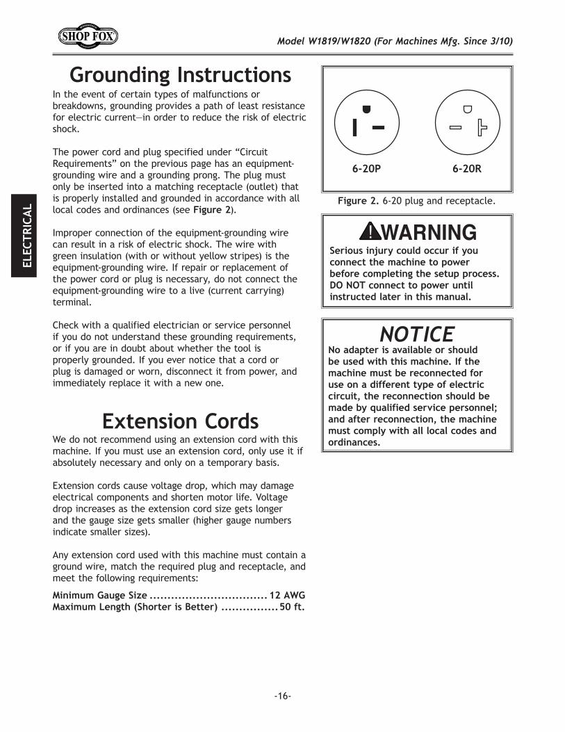
The power cord and plug specified under “Circuit Requirements” on the previous page has an equipment-grounding wire and a grounding prong. The plug must only be inserted into a matching receptacle (outlet) that is properly installed and grounded in accordance with all local codes and ordinances (see 2).
Improper connection of the equipment-grounding wire can result in a risk of electric shock. The wire with green insulation (with or without yellow stripes) is the equipment-grounding wire. If repair or replacement of the power cord or plug is necessary, do not connect the equipment-grounding wire to a live (current carrying) terminal. Check with a qualified electrician or service personnel if you do not understand these grounding requirements, or if you are in doubt about whether the tool is properly grounded. If you ever notice that a cord or plug is damaged or worn, disconnect it from power, and immediately replace it with a new one.
6-20 plug and receptacle.
No adapter is available or should be used with this machine. If the machine must be reconnected for use on a different type of electric circuit, the reconnection should be made by qualified service personnel; and after reconnection, the machine must comply with all local codes and ordinances.We do not recommend using an extension cord with this
machine. If you must use an extension cord, only use it if absolutely necessary and only on a temporary basis.
Extension cords cause voltage drop, which may damage electrical components and shorten motor life. Voltage drop increases as the extension cord size gets longer and the gauge size gets smaller (higher gauge numbers indicate smaller sizes).
Any extension cord used with this machine must contain a ground wire, match the required plug and receptacle, and meet the following requirements:
-17-
This machine has been carefully packaged for safe transportation. If you notice the machine has been damaged during shipping, please contact your authorized Shop Fox dealer immediately.
The following items are needed, but not included, to setup your machine.
• Safety Glasses for Each Person ..........................1• Degreaser or Solvent for Cleaning ................Varies• Disposable Rags for Cleaning ......................Varies• Straightedge ................................................1• Level .........................................................1• Dust Collection System ...................................1• 4" Dust Hose ................................................1• 4" Hose Clamp ..............................................1• Assistant for Lifting .......................................1• Needle Nose Pliers ........................................1• Wrench or Socket 17mm .................................1• Wrenches or Sockets 13mm ..............................2• Wrench or Socket 10mm .................................1• Wrench 14mm ..............................................1• Adjustable Wrench ........................................1
-18-
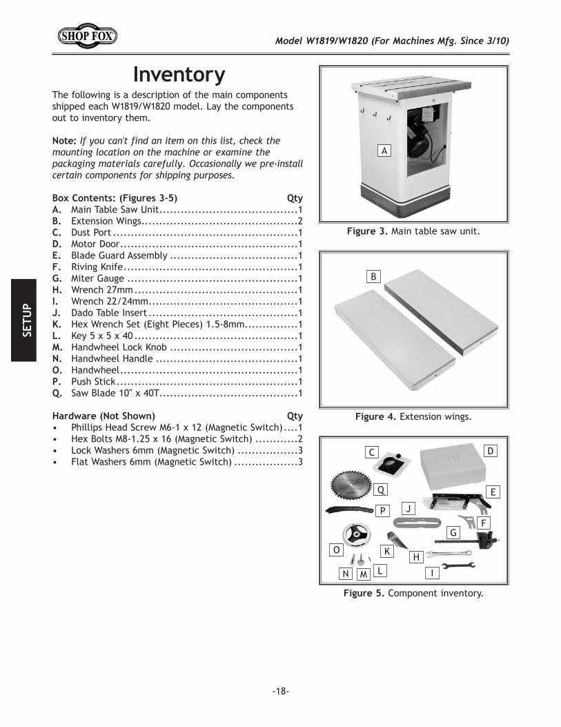
The following is a description of the main components shipped each W1819/W1820 model. Lay the components out to inventory them.
Main Table Saw Unit .......................................1Extension Wings ............................................2
Dust Port ....................................................1Motor Door ..................................................1Blade Guard Assembly ....................................1
Riving Knife .................................................1 Miter Gauge ................................................1 Wrench 27mm ..............................................1
Wrench 22/24mm ..........................................1Dado Table Insert ..........................................1Hex Wrench Set (Eight Pieces) 1.5-8mm ...............1Key 5 x 5 x 40 ..............................................1
Handwheel Lock Knob ....................................1 Handwheel Handle ........................................1 Handwheel ..................................................1
Push Stick ...................................................1Saw Blade 10" x 40T .......................................1
• Phillips Head Screw M6-1 x 12 (Magnetic Switch) ....1• Hex Bolts M8-1.25 x 16 (Magnetic Switch) ............2• Lock Washers 6mm (Magnetic Switch) .................3• Flat Washers 6mm (Magnetic Switch) ..................3
Main table saw unit.
A
Extension wings.
B
Component inventory.
HO
P
Q
I
J
K
LMN
C D
E
FG

-19-
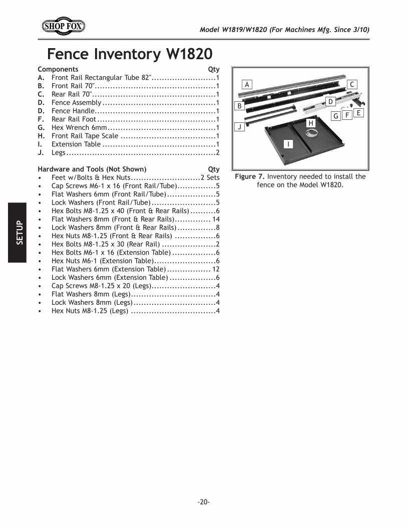
Front Rail Rectangular Tube 62" .........................1 Front Rail Tape Scale .....................................1 Front Rail 50"...............................................1 Rear Rail 50" ................................................1
Fence Assembly ............................................1 Fence Handle ...............................................1 Rear Rail Foot M12-1.75 ..................................1 Hex Wrench 6mm ..........................................1
Extension Table 27" x 133⁄4" .............................1
• Cap Screws M6-1 x 16 (Front Rail/Tube) ...............3• Flat Washers 6mm (Front Rail/Tube) ...................3• Lock Washers (Front Rail/Tube) .........................3• Hex Bolts M8-1.25 x 40 (Front & Rear Rails) ..........6• Flat Washers 8mm (Front & Rear Rails) .............. 14• Lock Washers 8mm (Front & Rear Rails) ...............8• Hex Nuts M8-1.25 (Front & Rear Rails) ................6• Hex Bolts M8-1.25 x 30 (Rear Rail) .....................2• Hex Bolts M6-1 x 16 (Extension Table) .................4• Hex Nuts M6-1 (Extension Table) ........................4• Flat Washers 6mm (Extension Table) ...................8• Lock Washers 6mm (Extension Table) ..................4
Inventory needed to install the fence on the Model W1819.
E
FG H I
AB C
D
-20-
Front Rail Rectangular Tube 82" .........................1 Front Rail 70"...............................................1 Rear Rail 70" ................................................1 Fence Assembly ............................................1 Fence Handle ...............................................1 Rear Rail Foot ..............................................1 Hex Wrench 6mm ..........................................1 Front Rail Tape Scale .....................................1
Extension Table ............................................1 Legs ..........................................................2
• Feet w/Bolts & Hex Nuts ...........................2 Sets• Cap Screws M6-1 x 16 (Front Rail/Tube) ...............5• Flat Washers 6mm (Front Rail/Tube) ...................5• Lock Washers (Front Rail/Tube) .........................5• Hex Bolts M8-1.25 x 40 (Front & Rear Rails) ..........6• Flat Washers 8mm (Front & Rear Rails) .............. 14• Lock Washers 8mm (Front & Rear Rails) ...............8• Hex Nuts M8-1.25 (Front & Rear Rails) ................6• Hex Bolts M8-1.25 x 30 (Rear Rail) .....................2• Hex Bolts M6-1 x 16 (Extension Table) .................6• Hex Nuts M6-1 (Extension Table) ........................6• Flat Washers 6mm (Extension Table) ................. 12• Lock Washers 6mm (Extension Table) ..................6• Cap Screws M8-1.25 x 20 (Legs) .........................4• Flat Washers 8mm (Legs) .................................4• Lock Washers 8mm (Legs) ................................4• Hex Nuts M8-1.25 (Legs) .................................4
Inventory needed to install the fence on the Model W1820.
EFGH
I
A
B
J
C
D
-21-
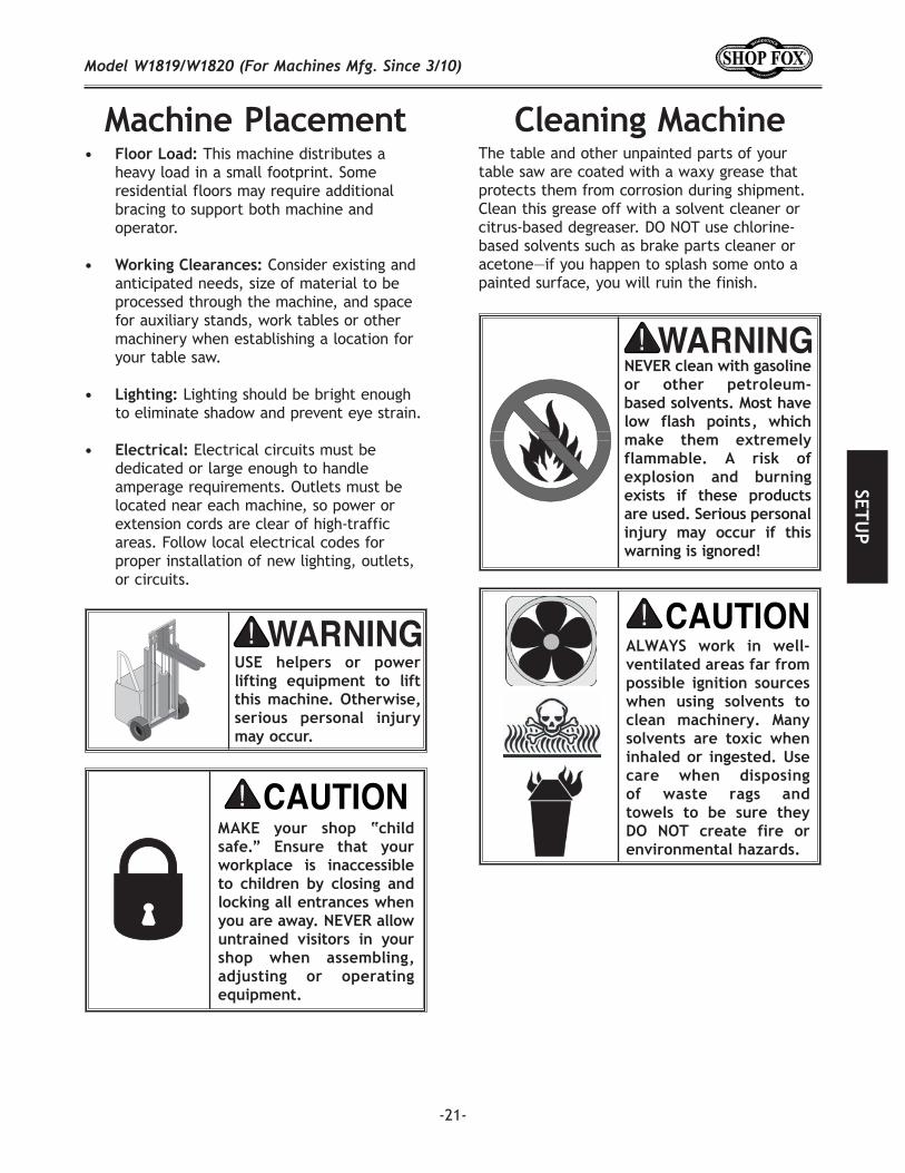
This machine distributes a heavy load in a small footprint. Some residential floors may require additional bracing to support both machine and operator.
Consider existing and anticipated needs, size of material to be processed through the machine, and space for auxiliary stands, work tables or other machinery when establishing a location for your table saw.
Lighting should be bright enough to eliminate shadow and prevent eye strain.
Electrical circuits must be dedicated or large enough to handle amperage requirements. Outlets must be located near each machine, so power or extension cords are clear of high-traffic areas. Follow local electrical codes for proper installation of new lighting, outlets, or circuits.
The table and other unpainted parts of your table saw are coated with a waxy grease that protects them from corrosion during shipment. Clean this grease off with a solvent cleaner or citrus-based degreaser. DO NOT use chlorine-based solvents such as brake parts cleaner or acetone—if you happen to splash some onto a painted surface, you will ruin the finish.
-22-
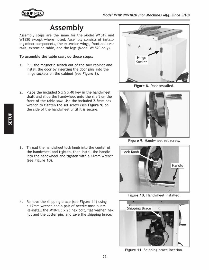
Assembly steps are the same for the Model W1819 and W1820 except where noted. Assembly consists of install-ing minor components, the extension wings, front and rear rails, extension table, and the legs (Model W1820 only).
Pull the magnetic switch out of the saw cabinet and install the door by inserting the door pins into the hinge sockets on the cabinet (see ).
Handwheel installed.
Door installed.
Hinge Socket
Handwheel set screw.
Lock Knob
Handle
Shipping brace location.
Shipping Brace
Place the included 5 x 5 x 40 key in the handwheel shaft and slide the handwheel onto the shaft on the front of the table saw. Use the included 2.5mm hex wrench to tighten the set screw (see ) on the side of the handwheel until it is secure.
Thread the handwheel lock knob into the center of the handwheel and tighten, then install the handle into the handwheel and tighten with a 14mm wrench (see ).
Remove the shipping brace (see ) using a 17mm wrench and a pair of needle nose pliers. Re-install the M10-1.5 x 25 hex bolt, flat washer, hex nut and the cotter pin, and save the shipping brace.
-23-
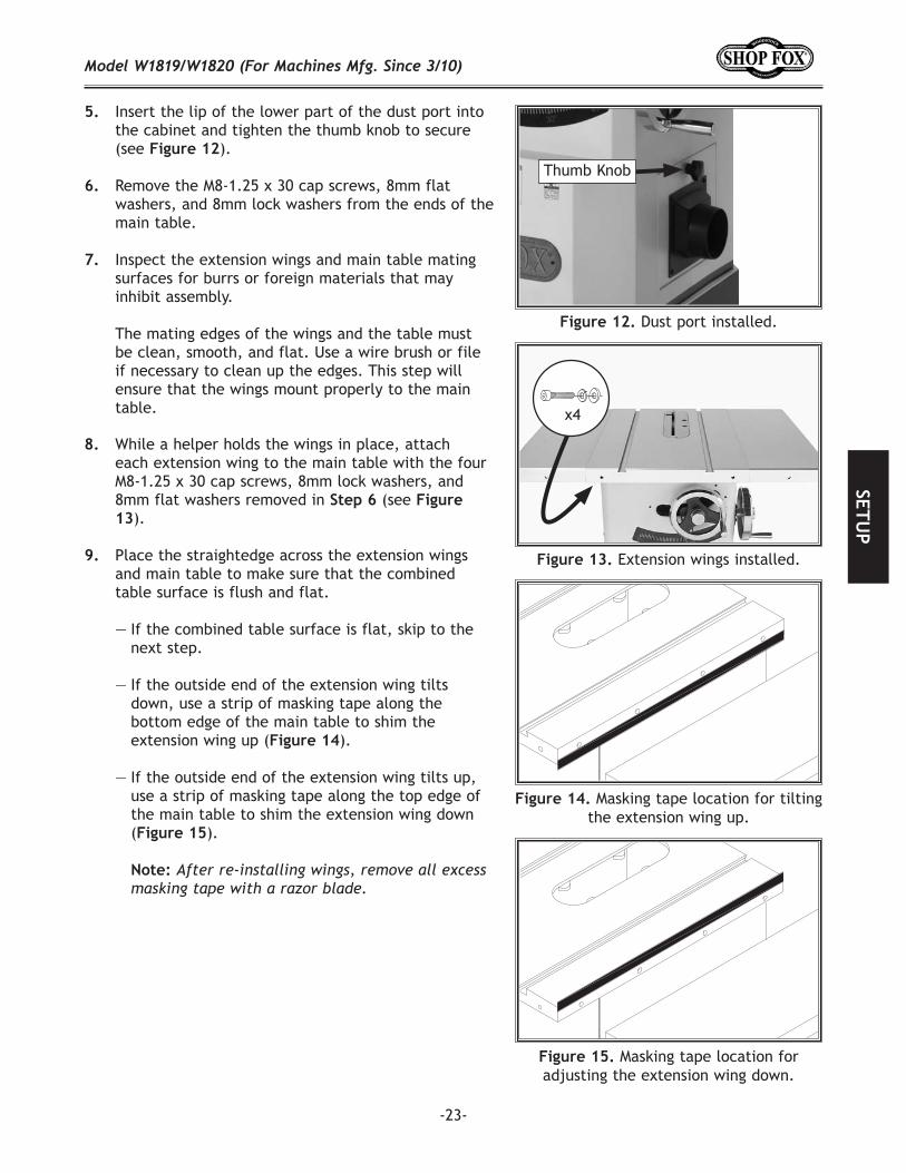
Insert the lip of the lower part of the dust port into the cabinet and tighten the thumb knob to secure (see ).
Remove the M8-1.25 x 30 cap screws, 8mm flat washers, and 8mm lock washers from the ends of the main table.
Inspect the extension wings and main table mating surfaces for burrs or foreign materials that may inhibit assembly.
The mating edges of the wings and the table must be clean, smooth, and flat. Use a wire brush or file if necessary to clean up the edges. This step will ensure that the wings mount properly to the main table.
While a helper holds the wings in place, attach each extension wing to the main table with the four M8-1.25 x 30 cap screws, 8mm lock washers, and 8mm flat washers removed in (see
).
Place the straightedge across the extension wings and main table to make sure that the combined table surface is flush and flat.
— If the combined table surface is flat, skip to the next step.
— If the outside end of the extension wing tilts down, use a strip of masking tape along the bottom edge of the main table to shim the extension wing up ( ).
— If the outside end of the extension wing tilts up, use a strip of masking tape along the top edge of the main table to shim the extension wing down ( ).
Masking tape location for tilting the extension wing up.
Masking tape location for adjusting the extension wing down.
Extension wings installed.
x4
Dust port installed.
Thumb Knob
-24-
Install the front rail onto the table and extension wings with four M8-1.25 x 40 hex bolts, eight 8mm flat washers, four 8mm lock washers, and four M8-1.25 hex nuts, as shown in .
Before final tightening, make sure the front rail is set 3⁄16" below the beveled edge along the entire length of the table.
Attach the rear rail to the holes on the main table using two M8-1.25 x 30 hex bolts, 8mm lock washers and 8mm flat washers, as shown in .
Secure the rear rail to the extension wings with two M8-1.25 x 40 hex bolts, four 8mm flat washers, two 8mm lock washers and two M8-1.25 hex nuts.
: Install the 62" front rail tube onto the 50" front rail with the three M6-1 x 16 cap screws, 6mm flat washers, and 6mm lock washers, as shown in .
Install the 82" front rail tube onto the 70" front rail with five M6-1 x 16 cap screws, 6mm lock washers, and 6mm flat washers, as shown in
.
Front rail installed (W1819).
Model W1819 tube attached to front rail.
x3
Model W1820 tube attached to front rail.
x5
Rear rail installed (W1820).
x2
Rail Tube
Rail Tube
-25-
Install the extension table between the front and rear rails with the four M6-1 x 16 hex bolts, eight 6mm flat washers, four 6mm lock washers, and four M6-1 hex nuts, as shown in .
Using a long straightedge, adjust the extension table so it is flat (both flush and parallel) with the main table and extension wings ( ), then tighten the fasteners.
Remove the six M6-1 x 16 hex bolts, (12) 6mm flat washers, six 6mm lock washers, and six M6-1 hex nuts from the extension table.
While an assistant holds the extension table between the front and rear rails, fasten the extension table to the rails with the fasteners removed in .
Thread the feet into the legs with the two M8-1.25 x 60 hex bolts, place the legs under the table, and thread the feet out until the top of each leg is against the underside corner of the table.
Use the four M8-1.25 x 20 cap screws, 8mm lock washers, 8mm flat washers, and M8-1.25 hex nuts to secure the legs to the end of the extension table, as shown in .
Verifying rear rail is flush with bottom of T-slot.
. Model W1819 extension table installed.
Adjusting Model W1819 extension table flush with wing and table.
Model W1820 extension table installed.
x4
Foot
-26-
Adjust the extension table so it is flat (both flush and parallel) with the main table, using a long straightedge (similar to the method shown in
). This can be done by loosening the mounting bolts and adjusting the feet up/down as needed.
Tighten the extension table mounting bolts, and tighten the hex nuts on the feet up against the legs so they will not move.
Attach the fence handle to the fence and thread the rear rail foot into the bottom of the fence (see
).
Place the fence on the rails on the right hand side of the blade (see ).
Slide the miter gauge into the T-slot on the left hand side of the blade.
Install the magnetic switch onto the bottom left hand side of the front rail using two M6-1 x 12 hex bolts, 6mm lock washers, and 6mm flat washers, as shown in .
Secure the top of the switch to the rail with an M6-1 x 12 Phillip head screw, 6mm lock washer, and flat washer.
Remove the table insert by unscrewing the screw that fastens it to the table.
Raise the arbor all the way up and set the blade angle at 0º.
Remove the arbor nut and arbor flange from the arbor, slide on the included 10" saw blade, making sure the teeth face the front of the saw, then install the arbor flange and arbor nut onto the blade. See
for additional details.
Fence assembled.
Fence installed on rails.
Cam Cam Foot
Magnetic switch installed.
Rear Foot
Handle
-27-
Put on a pair of heavy leather gloves and use the included arbor wrenches to tighten the arbor nut (turn clockwise to tighten), as shown in .
Slide the fence along the rail. If it drags across the table, then adjust the foot at the rear of the fence with a 6mm hex wrench to raise the fence off of the table, just enough so that the gap between the fence and the table is even from front to back.
Slide the fence up against the right hand edge of the miter slot, and lock it in place. Examine how the fence lines up with the miter slot (see 28).
— If the fence/miter slot are still parallel with the blade, proceed to .
— If the fence is not parallel to the blade/miter slot, then you MUST adjust the fence, as described in on , so that it is parallel to the blade.
— If the miter slot is not parallel with the blade, you must follow the procedures described in
on .
Since the adhesive fence scale will be difficult to remove once it installed, determine whether you will use the pointer window on the right or the left side of the fence before installing the scale.
The pointer window may come pre-installed on the left side of the fence. However, we recommend loosening the mounting screws on the window and re-installing it on the right side of the fence (see ) so workpieces will not cover the pointer window when preparing to cut.
Securing blade.
Checking fence parallelism with blade.
Aligning rail tape with scale pointer.
Screws
Pointer Window
-28-
On the Model W1819, if you move the pointer window to the right side of the fence, you may have to trim the last two inches of the scale so it will not protrude past the end of the fence tube.
One option for using the pointer window on the left side of the fence is to use it in conjunction with a small, left-reading scale (not included).
Slide the fence up against the saw blade and lock it in place.
Place the front rail tape scale on the fence tube, making sure it is parallel with the tube and that the "0" end is directly under the red line on the pointer window, as shown in .
Lightly mark the "0" location on the fence tube with a pencil, then remove the fence.
Peel the tape and carefully align the "0" mark on the scale with the pencil mark you made on the fence tube.
— If you make a mistake, loosen the screws on the pointer window, slide the fence against the blade, adjust the pointer window so the red line on the window is over the 0" mark on the tape, then secure the screws.
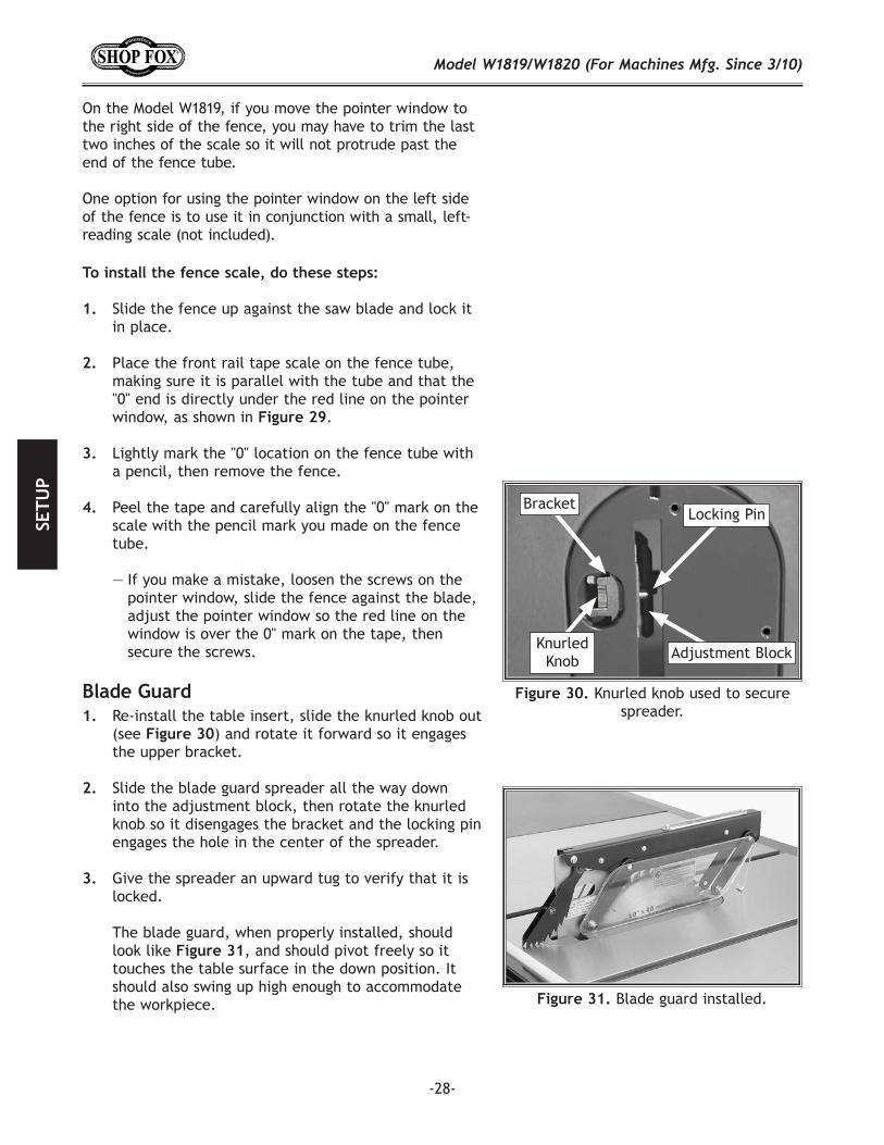
Re-install the table insert, slide the knurled knob out (see ) and rotate it forward so it engages the upper bracket.
Slide the blade guard spreader all the way down into the adjustment block, then rotate the knurled knob so it disengages the bracket and the locking pin engages the hole in the center of the spreader.
Give the spreader an upward tug to verify that it is locked.
The blade guard, when properly installed, should look like , and should pivot freely so it touches the table surface in the down position. It should also swing up high enough to accommodate the workpiece. Blade guard installed.
Knurled knob used to secure spreader.
Locking Pin
Knurled Knob
Bracket
Adjustment Block
-29-
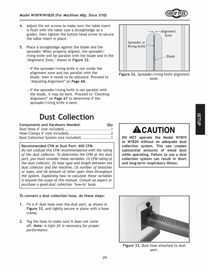
Spreader/riving knife alignment zone.
Adjust the set screws to make sure the table insert is flush with the table (use a straightedge as a guide), then tighten the button head screw to secure the table insert in place.
. Place a straightedge against the blade and the spreader. When properly aligned, the spreader/riving knife will be parallel with the blade and in the "Alignment Zone," shown in .
— If the spreader/riving knife is not inside the alignment zone and not parallel with the blade, then it needs to be adjusted. Proceed to "Adjusting Alignment on .
— If the spreader/riving knife is not parallel with the blade, it may be bent. Proceed to "Checking Alignment on to determine if the spreader/riving knife is bent.
To connect a dust collection hose, do these steps:
1. Fit a 4" dust hose over the dust port, as shown in Figure 33, and tightly secure in place with a hose clamp.
2. Tug the hose to make sure it does not come off. A tight fit is necessary for proper performance.
Dust Hose 4 " (not included) ...................................1Hose Clamps 4" (not included) ................................2Dust Collection System (not included) ......................1
Dust hose attached to dust port.
-30-
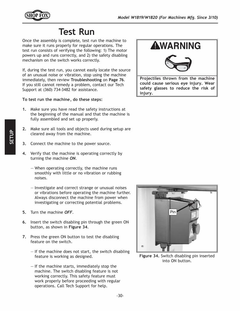
Switch disabling pin inserted into ON button.
Pin
Once the assembly is complete, test run the machine to make sure it runs properly for regular operations. The test run consists of verifying the following: 1) The motor powers up and runs correctly, and 2) the safety disabling mechanism on the switch works correctly.
If, during the test run, you cannot easily locate the source of an unusual noise or vibration, stop using the machine immediately, then review on . If you still cannot remedy a problem, contact our Tech Support at (360) 734-3482 for assistance.
Make sure you have read the safety instructions at the beginning of the manual and that the machine is fully assembled and set up properly.
Make sure all tools and objects used during setup are cleared away from the machine.
Connect the machine to the power source.
Verify that the machine is operating correctly by turning the machine .
— When operating correctly, the machine runs smoothly with little or no vibration or rubbing noises.
— Investigate and correct strange or unusual noises or vibrations before operating the machine further. Always disconnect the machine from power when investigating or correcting potential problems.
Turn the machine .
Insert the switch disabling pin through the green ON button, as shown in .
Press the green ON button to test the disabling feature on the switch.
— If the machine does not start, the switch disabling feature is working as designed.
— If the machine starts, immediately stop the machine. The switch disabling feature is not working correctly. This safety feature must work properly before proceeding with regular operations. Call Tech Support for help.
-31-
This machine will perform many types of operations that are beyond the scope of this manual. Many of these operations can be dangerous or deadly if performed incorrectly.
The instructions in this section are written with the understanding that the operator has the necessary knowledge and skills to operate this machine.
If you are an inexperienced operator, we strongly recommend that you read books or trade articles, or seek training from an experienced Table Saw operator before performing any unfamiliar operations.
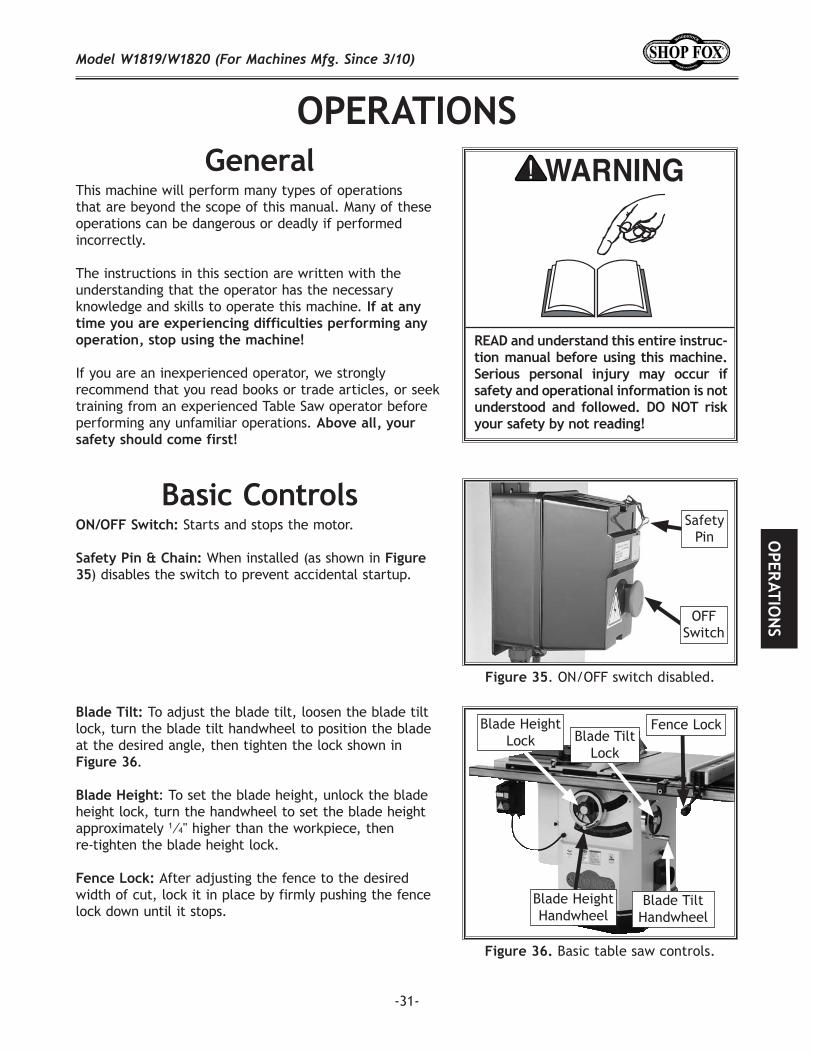
ON/OFF Switch: Starts and stops the motor.
Safety Pin & Chain: When installed (as shown in Figure 35) disables the switch to prevent accidental startup.
. ON/OFF switch disabled.
Safety Pin
OFF Switch
Blade Tilt: To adjust the blade tilt, loosen the blade tilt lock, turn the blade tilt handwheel to position the blade at the desired angle, then tighten the lock shown in Figure 36.
Blade Height: To set the blade height, unlock the blade height lock, turn the handwheel to set the blade height approximately 1⁄4" higher than the workpiece, then re-tighten the blade height lock.
Fence Lock: After adjusting the fence to the desired width of cut, lock it in place by firmly pushing the fence lock down until it stops.
Blade Height Lock Blade Tilt
Lock
Blade Height Handwheel
Blade Tilt Handwheel
Fence Lock
Basic table saw controls.
-32-
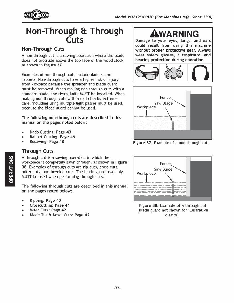
A non-through cut is a sawing operation where the blade does not protrude above the top face of the wood stock, as shown in .
Examples of non-through cuts include dadoes and rabbets. Non-through cuts have a higher risk of injury from kickback because the spreader and blade guard must be removed. When making non-through cuts with a standard blade, the riving knife MUST be installed. When making non-through cuts with a dado blade, extreme care, including using multiple light passes must be used, because the blade guard cannot be used.
Dado Cutting:Rabbet Cutting:Resawing:
Example of a through cut (blade guard not shown for illustrative
clarity).
. Example of a non-through cut.
A through cut is a sawing operation in which the workpiece is completely sawn through, as shown in
. Examples of through cuts are rip cuts, cross cuts, miter cuts, and beveled cuts. The blade guard assembly MUST be used when performing through cuts.
Ripping:Crosscutting:Miter Cuts:Blade Tilt & Bevel Cuts:
-33-
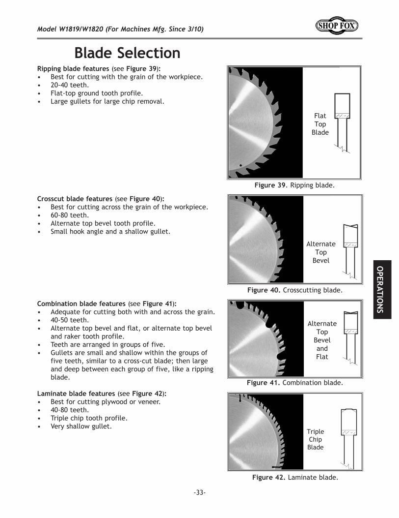
(see )• Best for cutting with the grain of the workpiece.• 20-40 teeth. • Flat-top ground tooth profile. • Large gullets for large chip removal.
. Ripping blade.
(see ) • Best for cutting across the grain of the workpiece.• 60-80 teeth. • Alternate top bevel tooth profile. • Small hook angle and a shallow gullet.
(see ) • Adequate for cutting both with and across the grain.• 40-50 teeth. • Alternate top bevel and flat, or alternate top bevel
and raker tooth profile. • Teeth are arranged in groups of five.• Gullets are small and shallow within the groups of
five teeth, similar to a cross-cut blade; then large and deep between each group of five, like a ripping blade.
(see ) • Best for cutting plywood or veneer.• 40-80 teeth. • Triple chip tooth profile. • Very shallow gullet.
Crosscutting blade.
Laminate blade.
Combination blade.
-34-
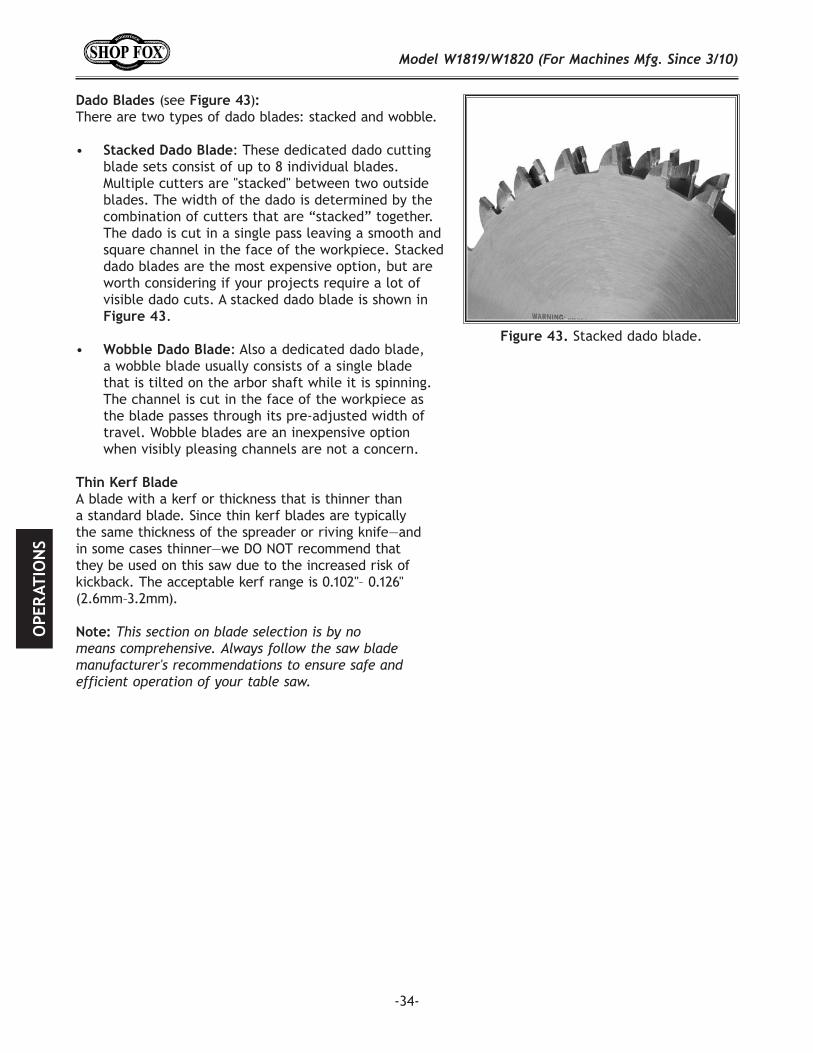
Stacked dado blade.
(see )There are two types of dado blades: stacked and wobble.
• : These dedicated dado cutting blade sets consist of up to 8 individual blades. Multiple cutters are "stacked" between two outside blades. The width of the dado is determined by the combination of cutters that are “stacked” together. The dado is cut in a single pass leaving a smooth and square channel in the face of the workpiece. Stacked dado blades are the most expensive option, but are worth considering if your projects require a lot of visible dado cuts. A stacked dado blade is shown in
.
• : Also a dedicated dado blade, a wobble blade usually consists of a single blade that is tilted on the arbor shaft while it is spinning. The channel is cut in the face of the workpiece as the blade passes through its pre-adjusted width of travel. Wobble blades are an inexpensive option when visibly pleasing channels are not a concern.
A blade with a kerf or thickness that is thinner than a standard blade. Since thin kerf blades are typically the same thickness of the spreader or riving knife—and in some cases thinner—we DO NOT recommend that they be used on this saw due to the increased risk of kickback. The acceptable kerf range is 0.102"– 0.126" (2.6mm–3.2mm).
-35-
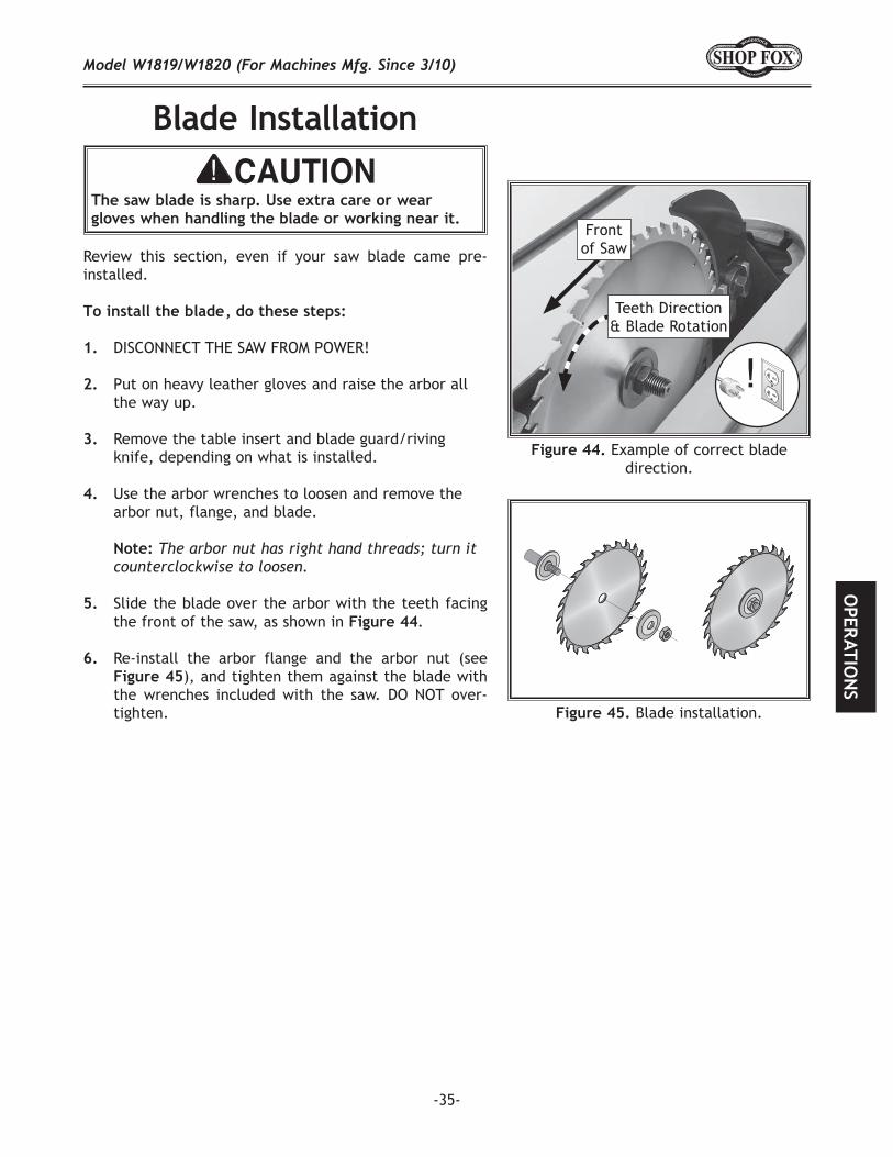
The saw blade is sharp. Use extra care or wear gloves when handling the blade or working near it.
Review this section, even if your saw blade came pre-installed.
DISCONNECT THE SAW FROM POWER!
Put on heavy leather gloves and raise the arbor all the way up.
Remove the table insert and blade guard/riving knife, depending on what is installed.
Use the arbor wrenches to loosen and remove the
arbor nut, flange, and blade.
Slide the blade over the arbor with the teeth facing the front of the saw, as shown in
Re-install the arbor flange and the arbor nut (see ), and tighten them against the blade with
the wrenches included with the saw. DO NOT over-tighten.
Example of correct blade direction.
Teeth Direction & Blade Rotation
Front of Saw
45 Blade installation.
-36-
The term "blade guard" refers to the assembly that con-sists of the clear polycarbonate shield, the spreader, and the anti-kickback pawls on each side of the spreader ( ). Each of these components have important safety functions during the operation of the saw.
The clear polycarbonate guard allows the operator to see the blade cut the workpiece during operation. This guard is designed to lift as the workpiece is pushed into the blade and remain in contact with the workpiece throughout the entire cut.
The guard reduces injury risk by providing a barrier around the blade that prevents accidental contact and contains flying wood chips.
To ensure that the guard does its job effectively, it must always be in the downward position against the table in the resting position during idle operation, and the hinge mechanism must be maintained in good working condition so the guard can freely pivot up and down to accommodate the height of the workpiece and return to the table surface.
The spreader is a metal plate that prevents the newly cut kerf of the workpiece from pinching the backside of the blade, causing kickback. The spreader also acts as a barrier behind the blade to shield hands from being pulled into the blade if a kickback occurs.
Blade guard assembly components.
In order to work properly, the spreader cannot be bent or misaligned with the blade. If the spreader gets accidentally bent, take the time to straighten it or just replace it. Using a bent or misaligned spreader will increase the risk of kickback!
To ensure that the blade spreader works safely, the following requirements MUST be met when installing new blades:
The spreader MUST be aligned/adjusted to the blade.
-37-
The anti-kickback pawls allow the workpiece to travel in only one direction. If the workpiece moves backwards, such as during a kickback, the pawls will dig into the workpiece to slow or stop it.
To work properly, the pawls must return to their bottom-most position after pivoting, as shown in Figure 47, and they must not be engaged in the arresting hooks. If the pawls fail to return to the bottom position, the pivot spring may have been dislodged or broken and will need to be fixed/replaced.
To disable the pawls, rotate the arresting hooks downward, then place the pawls on each of the hooks, as shown in Figure 48.
Use your best judgment before retracting the pawls, as they are provided for your safety. Certain situations could warrant retracting the pawls. For example, you might retract the pawls if you are concerned about them scratching a delicate workpiece, or if you believe that they will obstruct a narrow workpiece and cause feeding difficulty or loss of control.
. Pawls in return position.
. Pawl disabled.
Pawl
Arresting Hooks
Arresting Hooks (One Shown)
Pawl
To enable the pawls, lift up on each pawl and move them outward and down until they both touch the table surface, as shown in Figure 47.
The blade guard assembly MUST always be installed on the saw for all normal through cuts (those where the blade cuts all the way through the thickness of the workpiece).
The blade guard cannot be used on any non-through cuts (those in which the blade does not cut all the way through the thickness of the workpiece).
Sometimes the blade guard or its components can get in the way when cutting very narrow workpieces or other specialized cuts. Because the blade guard is provided to decrease your risk of injury, it should not be used if it gets in the way of making a safe cut. Use good judgment!
-38-
The riving knife works in the same manner as the spread-er on the blade guard assembly. It is a metal plate that prevents the newly cut workpiece from pinching the back-side of the blade and causing kickback.
The key difference between the spreader and the riving knife is that the riving knife mounts below the blade's highest point of rotation, as shown in .
The height difference between the riving knife and the blade allows the workpiece to pass over the blade during non-through cuts (those in which the blade does not cut all the way through the thickness of the workpiece).
The riving knife acts as a barrier behind the blade to reduce the risk of hands being pulled into the blade if a kickback occurs.
The riving knife must be kept within the range shown in Figure 50. For that reason, we only recommend using a 10" blade for operations that require use of the riving knife.
Height difference between riving knife and blade.
. Allowable top and bottom distances between riving knife and blade.
To ensure riving knife works safely, the following requirements MUST be met when installing new blades:
iving knife MUST be aligned to blade;
Use the riving knife for all non-through cuts made with a standard table saw blade (i.e., dadoes or rabbet cuts in which a dado blade is NOT used, and when using a tenoning jig).
Also, use the riving knife for those special operations where the blade guard or its components get in the way of safe operation, such as with very narrow cuts.
When Not to Use the Riving KnifeThe riving knife CANNOT be used with a dado blade that has a diameter smaller than 10." Otherwise, the riving knife height will exceed the blade height and the workpiece will hit the riving knife during the cut, forcing the operator into a dangerous situation of trying to turn the saw off with the workpiece stuck halfway through the cut.
In addition, although it is possible to use the riving knife for through cutting operations, the blade guard assembly offers far more injury protection and risk reduction than the riving knife. Therefore, we strongly recommend that you use the blade guard assembly instead of the riving knife for through cuts.

-39-
Some workpieces are not safe to cut or may require modification before they can be made safe to cut.
:
• Material Type: This machine is intended for cutting natural and man-made wood products, laminate covered wood products, and some plastics. Cutting drywall or cementitious backer board creates extremely fine dust and may reduce the life of the bearings. This machine is NOT designed to cut metal, glass, stone, tile, etc.; cutting these materials with a table saw may lead to injury.
• Foreign Objects: Nails, staples, dirt, rocks and other foreign objects are often embedded in wood. While cutting, these objects can become dislodged and hit the operator, cause kickback, or break the blade, which might then fly apart. Always visually inspect your workpiece for these items. If they can't be removed, DO NOT cut the workpiece.
Large/Loose Knots: Loose knots can become dislodged during the cutting operation. Large knots can cause kickback and machine damage. Choose workpieces that do not have large/loose knots or plan ahead to avoid cutting through them.
Wet or "Green" Stock: Cutting wood with a moisture content over 20% causes unnecessary wear on the blades, increases the risk of kickback, yields poor results.
• Excessive Warping: Workpieces with excessive cupping, bowing, or twisting are dangerous to cut because they are unstable and often unpredictable when being cut. DO NOT use workpieces with these characteristics!
• Minor Warping: Workpieces with slight cupping can be safely supported if the cupped side is facing the table or the fence.
-40-
"Ripping" means cutting with the grain of a natural wood workpiece. In other man-made materials such as MDF or plywood, ripping simply means cutting lengthwise.
Review on and take the necessary precautions to prevent kickback.
If using natural wood, joint one long edge of the workpiece on a jointer.
DISCONNECT THE SAW FROM POWER!
Ensure that the blade guard/spreader is installed.
Set the fence to the desired width of cut on the scale.
Adjust the blade height so the highest saw tooth protrudes approximately 1/4" above the workpiece.
Set up safety devices such as featherboards or other anti-kickback devices.
Rotate the blade by hand to make sure it does not come into contact with any of the safety devices.
Plug the saw into the power source, turn it and allow it to reach full speed.
Use a push stick to feed the workpiece through the saw blade, as shown in , until the workpiece is completely past the saw blade.
Typical ripping operation.
-41-
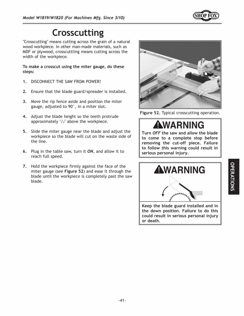
"Crosscutting" means cutting across the grain of a natural wood workpiece. In other man-made materials, such as MDF or plywood, crosscuttting means cutting across the width of the workpiece.
DISCONNECT THE SAW FROM POWER!
Ensure that the blade guard/spreader is installed.
Move the rip fence aside and position the miter gauge, adjusted to 90°, in a miter slot.
Adjust the blade height so the teeth protrude approximately 1/4" above the workpiece.
Slide the miter gauge near the blade and adjust the workpiece so the blade will cut on the waste side of the line.
Plug in the table saw, turn it and allow it to reach full speed.
Hold the workpiece firmly against the face of the miter gauge (see ) and ease it through the blade until the workpiece is completely past the saw blade.
Typical crosscutting operation.
-42-
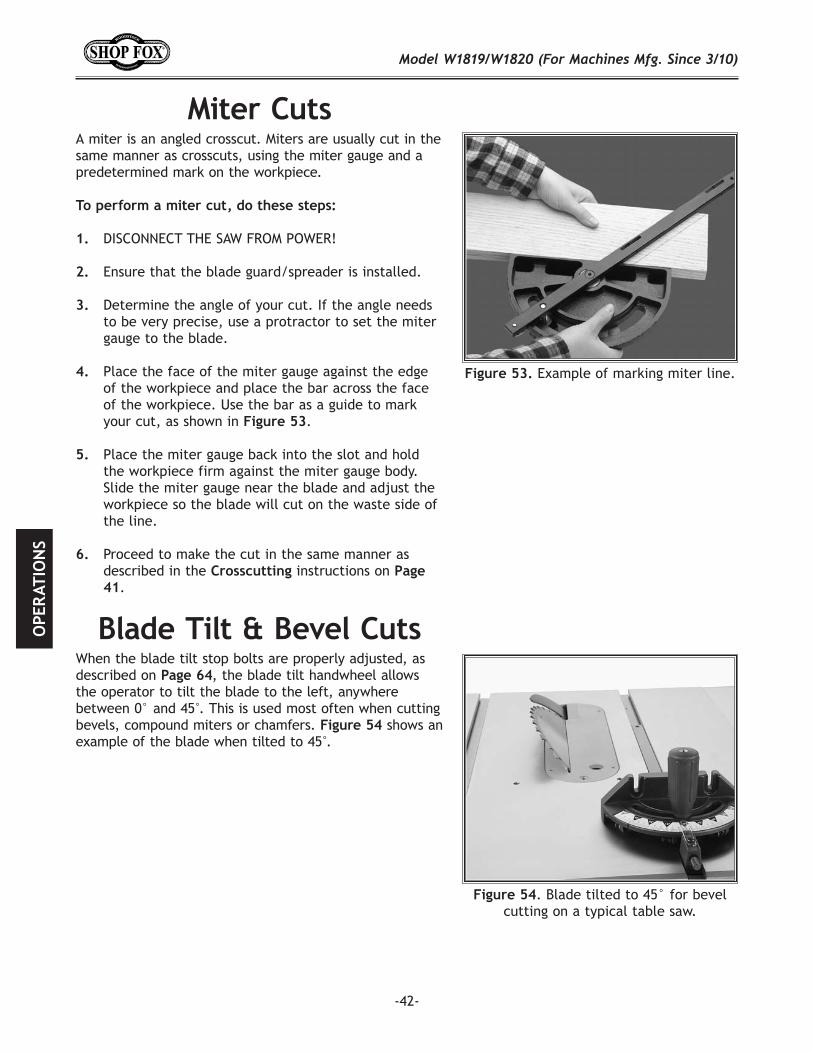
Example of marking miter line.
A miter is an angled crosscut. Miters are usually cut in the same manner as crosscuts, using the miter gauge and a predetermined mark on the workpiece.
DISCONNECT THE SAW FROM POWER!
Ensure that the blade guard/spreader is installed.
Determine the angle of your cut. If the angle needs to be very precise, use a protractor to set the miter gauge to the blade.
Place the face of the miter gauge against the edge of the workpiece and place the bar across the face of the workpiece. Use the bar as a guide to mark your cut, as shown in .
Place the miter gauge back into the slot and hold the workpiece firm against the miter gauge body. Slide the miter gauge near the blade and adjust the workpiece so the blade will cut on the waste side of the line.
Proceed to make the cut in the same manner as described in the instructions on
.
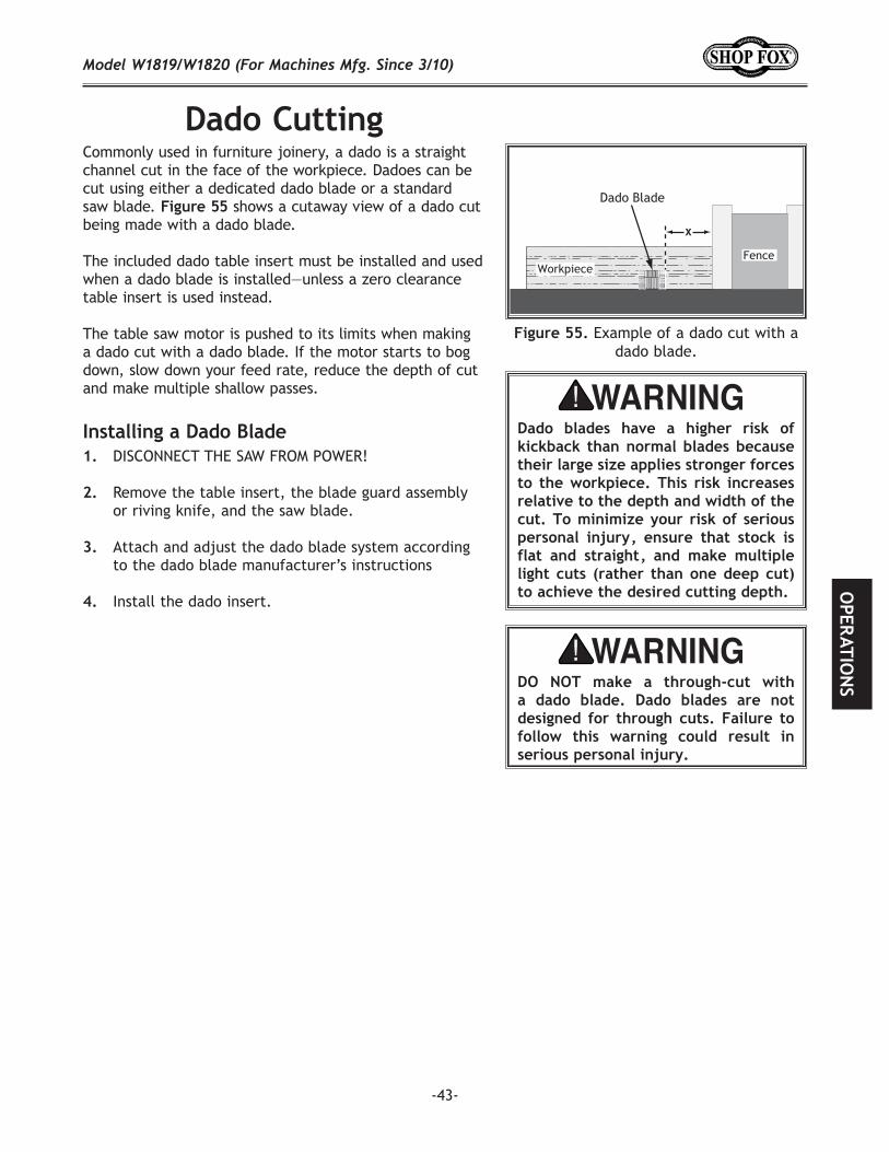
When the blade tilt stop bolts are properly adjusted, as described on , the blade tilt handwheel allows the operator to tilt the blade to the left, anywhere between 0° and 45°. This is used most often when cutting bevels, compound miters or chamfers. shows an example of the blade when tilted to 45°.
. Blade tilted to 45° for bevel cutting on a typical table saw.
-43-
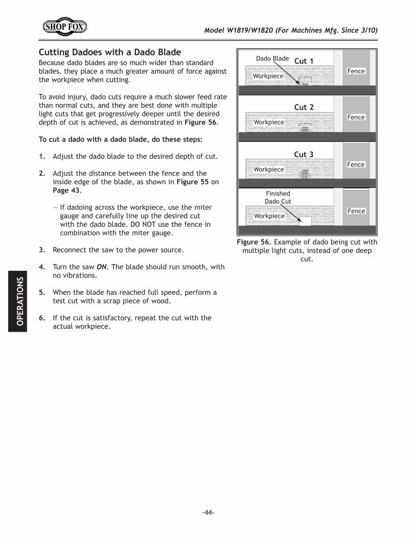
Commonly used in furniture joinery, a dado is a straight channel cut in the face of the workpiece. Dadoes can be cut using either a dedicated dado blade or a standard saw blade. Figure 55 shows a cutaway view of a dado cut being made with a dado blade.
The included dado table insert must be installed and used when a dado blade is installed—unless a zero clearance table insert is used instead.
The table saw motor is pushed to its limits when making a dado cut with a dado blade. If the motor starts to bog down, slow down your feed rate, reduce the depth of cut and make multiple shallow passes.
DISCONNECT THE SAW FROM POWER!
Remove the table insert, the blade guard assembly or riving knife, and the saw blade.
Attach and adjust the dado blade system according to the dado blade manufacturer’s instructions
Install the dado insert.
Example of a dado cut with a dado blade.
-44-
Because dado blades are so much wider than standard blades, they place a much greater amount of force against the workpiece when cutting.
To avoid injury, dado cuts require a much slower feed rate than normal cuts, and they are best done with multiple light cuts that get progressively deeper until the desired depth of cut is achieved, as demonstrated in Figure 56.
Adjust the dado blade to the desired depth of cut.
Adjust the distance between the fence and the inside edge of the blade, as shown in on
.
— If dadoing across the workpiece, use the miter gauge and carefully line up the desired cut with the dado blade. DO NOT use the fence in combination with the miter gauge.
Reconnect the saw to the power source.
Turn the saw . The blade should run smooth, with no vibrations.
When the blade has reached full speed, perform a test cut with a scrap piece of wood.
If the cut is satisfactory, repeat the cut with the actual workpiece.
Example of dado being cut with multiple light cuts, instead of one deep
cut.
Dado Blade
WorkpieceFence
Cut 1
WorkpieceFence
Cut 2
WorkpieceFence
Cut 3
FinishedDado Cut
WorkpieceFence
-45-
A ripping blade is typically the best blade to use for cutting dadoes when using a standard blade because it removes sawdust very efficiently. See for blade details.
DISCONNECT THE SAW FROM POWER!
Ensure that the riving knife and standard table insert are installed and properly adjusted.
Mark the width of the dado cut on the workpiece.Include marks on the edge of the workpiece so the cut path can be aligned when the workpiece is lying on the table.
Raise the blade up to the desired depth of cut (depth of dado channel desired).
— If dadoing across the workpiece, use the miter gauge to support the workpiece, and align the blade to cut one of the dado sides. DO NOT use the fence in combination with the miter gauge.
— If dadoing the length of a workpiece, align the blade to cut one of the dado sides as shown in
.
Reconnect the saw to the power source and turn the saw . Allow the blade to reach full speed.
Perform the cutting operation.
Re-adjust the fence so the blade is aligned with the other edge of the intended dado channel (
).
Continue making cuts toward the center of the dado until the dado is complete (see ).
Blade
WorkpieceFence
Cut 1
Single-blade dado first cut.
WorkpieceFence
Cut 2 Blade
Single-blade dado second cut.
Cuts 3+
59 Addtional cuts.
-46-
Sacrificial fence.
WorkpieceFence
Dado Blade
Sacrificial Fence
Rabbet cutting with a dado blade
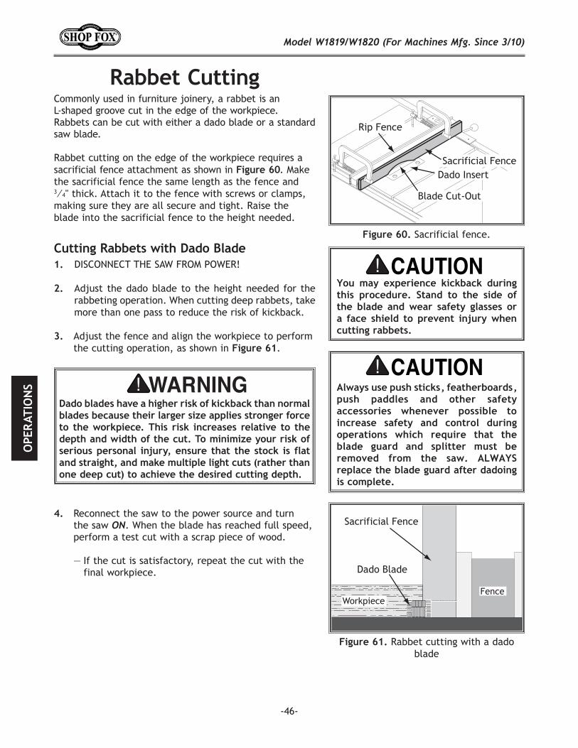
Commonly used in furniture joinery, a rabbet is an L-shaped groove cut in the edge of the workpiece. Rabbets can be cut with either a dado blade or a standard saw blade.
Rabbet cutting on the edge of the workpiece requires a sacrificial fence attachment as shown in . Make the sacrificial fence the same length as the fence and 3⁄4" thick. Attach it to the fence with screws or clamps, making sure they are all secure and tight. Raise the blade into the sacrificial fence to the height needed.
DISCONNECT THE SAW FROM POWER!
Adjust the dado blade to the height needed for the rabbeting operation. When cutting deep rabbets, take more than one pass to reduce the risk of kickback.
Adjust the fence and align the workpiece to perform the cutting operation, as shown in .
Reconnect the saw to the power source and turn the saw . When the blade has reached full speed, perform a test cut with a scrap piece of wood.
— If the cut is satisfactory, repeat the cut with the final workpiece.
Dado blades have a higher risk of kickback than normal blades because their larger size applies stronger force to the workpiece. This risk increases relative to the depth and width of the cut. To minimize your risk of serious personal injury, ensure that the stock is flat and straight, and make multiple light cuts (rather than one deep cut) to achieve the desired cutting depth.
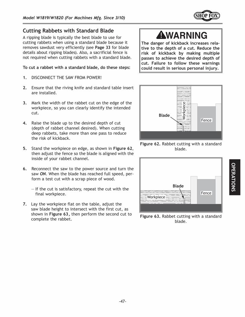
-47-
A ripping blade is typically the best blade to use for cutting rabbets when using a standard blade because it removes sawdust very efficiently (see Page 33 for blade details about ripping blades). Also, a sacrificial fence is not required when cutting rabbets with a standard blade.
DISCONNECT THE SAW FROM POWER!
Ensure that the riving knife and standard table insert are installed.
Mark the width of the rabbet cut on the edge of the workpiece, so you can clearly identify the intended cut.
Raise the blade up to the desired depth of cut (depth of rabbet channel desired). When cutting deep rabbets, take more than one pass to reduce the risk of kickback.
Stand the workpiece on edge, as shown in , then adjust the fence so the blade is aligned with the inside of your rabbet channel.
Reconnect the saw to the power source and turn the saw ON. When the blade has reached full speed, per-form a test cut with a scrap piece of wood.
— If the cut is satisfactory, repeat the cut with the final workpiece.
Lay the workpiece flat on the table, adjust the saw blade height to intersect with the first cut, as shown in then perform the second cut to complete the rabbet.
Rabbet cutting with a standard blade.
FenceBlade
Wor
kpie
ce
Rabbet cutting with a standard blade.
WorkpieceFence
Blade
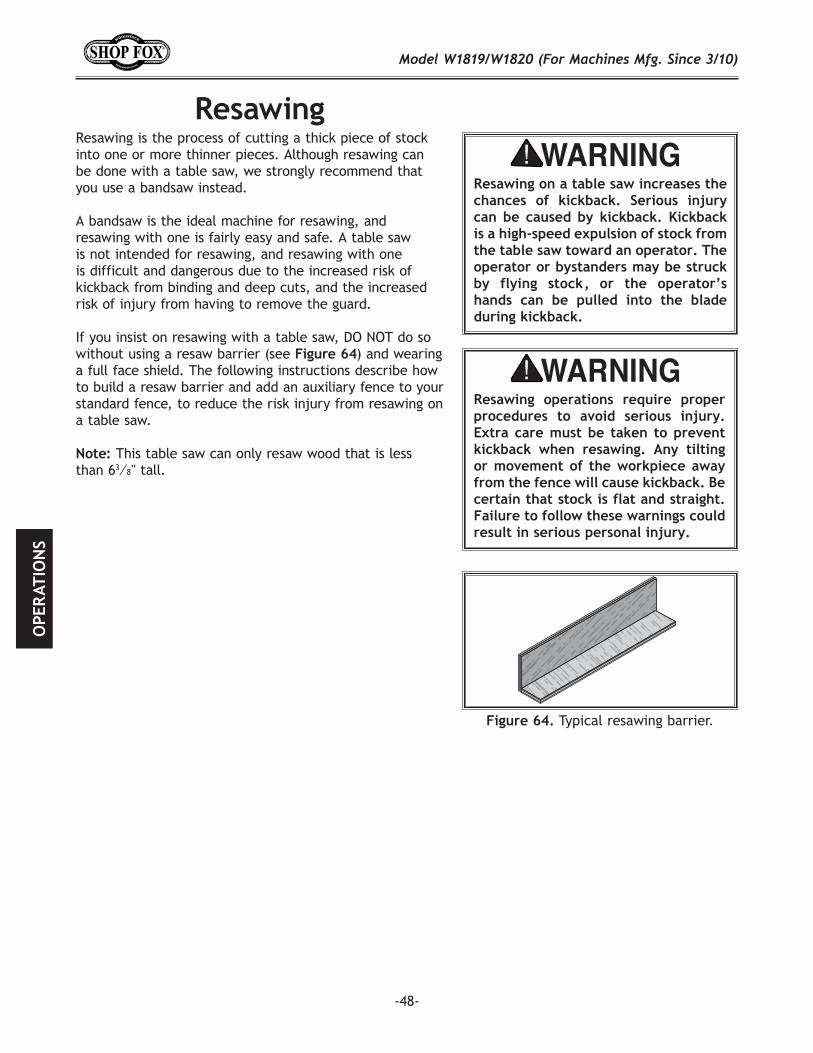
-48-
Resawing is the process of cutting a thick piece of stock into one or more thinner pieces. Although resawing can be done with a table saw, we strongly recommend that you use a bandsaw instead.
A bandsaw is the ideal machine for resawing, and resawing with one is fairly easy and safe. A table saw is not intended for resawing, and resawing with one is difficult and dangerous due to the increased risk of kickback from binding and deep cuts, and the increased risk of injury from having to remove the guard.
If you insist on resawing with a table saw, DO NOT do so without using a resaw barrier (see ) and wearing a full face shield. The following instructions describe how to build a resaw barrier and add an auxiliary fence to your standard fence, to reduce the risk injury from resawing on a table saw.
This table saw can only resaw wood that is less than 63⁄8" tall.
Typical resawing barrier.
-49-
The resaw barrier acts in tandem with the rip fence when resawing to provide tall support for the workpiece to minimize the probability of it binding against the blade and causing kickback.
Table Saw ........................................................1Jointer and Planer ............................. RecommendedClamps ................................................2 MinimumDrill and Drill Bits ...............................................1
Wood* 3⁄4" x 6" x Length of Table Saw Fence ...............1Wood* 3⁄4" x 3" x Length of Table Saw Fence ...............1Wood Screws #10 x 2" ..........................................4Wood Glue ........................................... As Needed
*
Cut your wood pieces to the size specified above. If you are using hardwood, cut the pieces oversize, then joint and plane them to the correct size to make sure they are square and flat.
Pre-drill and countersink 4 holes approximately 3⁄8" from the bottom of the 6" tall board. These will be use as pilot holes when attaching the board to another piece in the next step.
Glue the end of the 3" board, then clamp the boards at a 90° angle with the larger board in the vertical position, as shown in , fasten together with the wood screws. Clamping the resawing barrier.
#10 x 2"Wood Screw
AssembledResaw Barrier
3⁄4"
3⁄4"
The auxiliary fence is necessary if you are resawing a workpiece that is taller than it is wide. It should be no less than 1⁄2" shorter than the board to be resawn.
Hardwood or Plywood 3⁄4" x (Height) x Length of Table Saw Fence ........................................................1
Table Saw ........................................................1Jointer and Planer ............................. RecommendedClamps ................................................2 Minimum
-50-
The table saw motor is pushed to its limits when resawing. If the motor starts to bog down, slow down your feed rate. Motor overloading and blade wear can be reduced by using a ripping blade. Ripping blades are designed to clear the sawdust quickly.
Zero Clearance Insert ..........................................1Ripping Blade 10" ...............................................1Clamps ............................................................2Shop Made Auxiliary Fence ....................................1Shop Made Resaw Barrier ......................................1
DISCONNECT THE SAW FROM POWER!
Remove the standard table insert and the blade guard assembly.
Install a ripping blade and the riving knife, lower the blade below the table, then install a zero clearance table insert.
66 Auxiliary fence.
Cut the auxiliary fence board to size. If you are using hardwood, cut the board oversize, then joint and plane the board to the correct size to make sure the board is square and flat.
Unthread the fence face mounting hardware and remove the fence face from the fence assembly.
Place the auxiliary fence next the fence face you removed in , mark the location of the nine mounting holes on the auxiliary fence, then drill the holes.
Use the mounting hardware that had previously attached the fence face to attach the auxiliary fence. The end result should be similar to 66.
-51-
Attach the auxiliary fence to the standard fence and set it to the desired width.
Place the workpiece against the auxiliary fence and slide the resaw barrier against the workpiece, as shown in 67. Now clamp the resaw barrier to the top of the table saw at both ends.
Slide the workpiece over the blade to make sure it moves smoothly, then remove the workpiece.
Raise the blade approximately an inch, or close to half the height of the workpiece ( 68), whichever is less.
Plug in the table saw, turn it , and use a push stick or push block to feed the workpiece through the blade, using a slow and steady feed rate.
Flip the workpiece end for end, keeping the same side against the fence, and run the workpiece through the blade.
Repeat until the blade is close to half of the height of the board to be resawn. The ideal completed resaw cut will leave a 1⁄8" connection when the resawing is complete as shown in 68. Leaving a 1⁄8" connection will reduce the risk of kickback.
Turn the table saw, then separate the parts of the workpiece and hand plane the remaining ridge to remove it.
When finished resawing, remove the resaw barrier and auxiliary fence, then re-install the blade guard/spreader or riving knife and standard table insert.
. Ideal resaw workpiece setup.
(Front View)
68 Ideal completed resaw cut.
-52-
The following table saw accessories may be available through your local Woodstock International Inc. Dealer. If you do not have a dealer in your area, these products are also available through online deal-ers. Please call or e-mail Woodstock International Inc. Customer Service to get a current listing of deal-ers at: 1-800-840-8420 or at [email protected].
The Shop Fox produce perfect tenons for mortise and tenon joinery. This tenoning jig also adjusts for angled tenon cutting set-ups. Standard 3/8" x 3/4" miter bar fits all miter gauge slots including T-slots.
The Shop Fox can reduce the risk of kick-back and help you achieve consistent results. Designed to lock into standard 3/8" x 3/4" miter gauge slots, these featherboards are adjustable for various stock widths and miter slot locations. No drill-ing or bulky clamp arrangements.
The Shop Fox is constructed using top quality aluminum castings and plates which are machined to exacting tolerances. It has the perfect weight-use ratio to dampen vibration, yet is still light enough to easily slide the workpiece through the machining process. Its quality and precision are evident from the first cut. Cut tenons, dados, rail ends, and finger joints safely and with complete accuracy.
The Shop Fox can help you keep your hands a safe distance from blades and cutters while still maintaining control of the workpiece against machine fences. A true necessity when running narrow stock. Durable handle is designed for maximum control. Measure 131/2" overall.
The Shop Fox is the perfect companion for the Model W1819/W1820. It packs a 1 HP, 110V/220V, single-phase motor and 800 CFM air suction capacity.
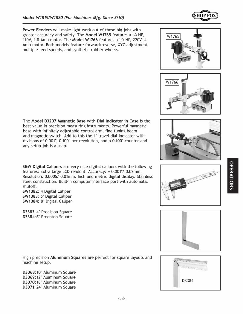
-53-
The is the best value in precision measuring instruments. Powerful magnetic base with infinitely adjustable control arm, fine tuning beam and magnetic switch. Add to this the 1" travel dial indicator with divisions of 0.001", 0.100" per revolution, and a 0.100" counter and any setup job is a snap.
are very nice digital calipers with the following features: Extra large LCD readout. Accuracy: ± 0.001"/ 0.02mm. Resolution: 0.0005/ 0.01mm. Inch and metric digital display. Stainless steel construction. Built-in computer interface port with automatic shutoff.
: 4 Digital Caliper: 6" Digital Caliper: 8" Digital Caliper
: 4" Precision Square : 6" Precision Square
High precision are perfect for square layouts and machine setup.
: 10" Aluminum Square 12" Aluminum Square 18" Aluminum Square 24" Aluminum Square
D3384
will make light work out of those big jobs with greater accuracy and safety. The features a 1⁄4 HP, 110V, 1.8 Amp motor. The features a 1⁄2 HP, 220V, 4 Amp motor. Both models feature forward/reverse, XYZ adjustment, multiple feed speeds, and synthetic rubber wheels.
W1765
W1766
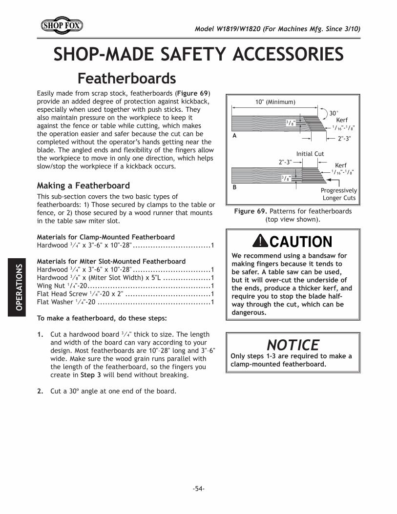
-54-
Easily made from scrap stock, featherboards ( )provide an added degree of protection against kickback, especially when used together with push sticks. They also maintain pressure on the workpiece to keep it against the fence or table while cutting, which makes the operation easier and safer because the cut can be completed without the operator’s hands getting near the blade. The angled ends and flexibility of the fingers allow the workpiece to move in only one direction, which helps slow/stop the workpiece if a kickback occurs.
This sub-section covers the two basic types of featherboards: 1) Those secured by clamps to the table or fence, or 2) those secured by a wood runner that mounts in the table saw miter slot.
Materials for Clamp-Mounted FeatherboardHardwood 3⁄4" x 3"-6" x 10"-28" ...............................1
Materials for Miter Slot-Mounted FeatherboardHardwood 3⁄4" x 3"-6" x 10"-28" ...............................1Hardwood 3⁄8" x (Miter Slot Width) x 5"L ...................1 Wing Nut 1/4"-20 .................................................1Flat Head Screw 1⁄4"-20 x 2" ..................................1Flat Washer 1⁄4"-20 .............................................1
To make a featherboard, do these steps:
Cut a hardwood board 3⁄4" thick to size. The length and width of the board can vary according to your design. Most featherboards are 10"–28" long and 3"–6" wide. Make sure the wood grain runs parallel with the length of the featherboard, so the fingers you create in will bend without breaking.
Cut a 30º angle at one end of the board.
A
B
30°
2"-3"
1/16"-1/8"Kerf
1/16"-1/8"Kerf2"-3"
10" (Minimum)
Initial Cut
Progressively Longer Cuts
3/8"
3/8"
Patterns for featherboards (top view shown).
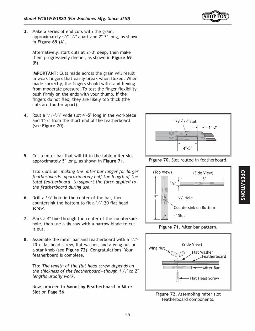
-55-
1"-2"
4"-5"
1/4"-3/8" Slot
Slot routed in featherboard.
5"
5"
4" Slot
(Top View) (Side View)
3/8"
Countersink on Bottom
1/4" Hole
Miter bar pattern.
(Side View)Wing Nut
Miter Bar
Featherboard
Flat Head Screw
Flat Washer
Assembling miter slot featherboard components.
Rout a 1⁄4"–3⁄8" wide slot 4"–5" long in the workpiece and 1"–2" from the short end of the featherboard (see ).
Cut a miter bar that will fit in the table miter slot approximately 5" long, as shown in .
Now, proceed to on .
Drill a 1⁄4" hole in the center of the bar, then countersink the bottom to fit a 1⁄4"-20 flat head screw.
Mark a 4" line through the center of the countersunk hole, then use a jig saw with a narrow blade to cut it out.
Assemble the miter bar and featherboard with a 1⁄4"-20 x flat head screw, flat washer, and a wing nut or a star knob (see ). Congratulations! Your featherboard is complete.
Make a series of end cuts with the grain, approximately 3⁄8"–1⁄4" apart and 2"–3" long, as shown in (A).
Alternatively, start cuts at 2"-3" deep, then make them progressively deeper, as shown in (B).
Cuts made across the grain will result in weak fingers that easily break when flexed. When made correctly, the fingers should withstand flexing from moderate pressure. To test the finger flexibility, push firmly on the ends with your thumb. If the fingers do not flex, they are likely too thick (the cuts are too far apart).
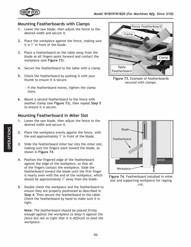
-56-
Lower the saw blade, then adjust the fence to the desired width and secure it.
Place the workpiece against the fence, making sure it is 1" in front of the blade.
Place a featherboard on the table away from the blade so all fingers point forward and contact the workpiece (see ).
Secure the featherboard to the table with a clamp.
Check the featherboard by pushing it with your thumb to ensure it is secure.
— If the featherboard moves, tighten the clamp more.
Mount a second featherboard to the fence with another clamp (see ), then repeat to ensure it is secure.
Lower the saw blade, then adjust the fence to the desired width and secure it.
Place the workpiece evenly against the fence, with the end approximately 1" in front of the blade.
Slide the featherboard miter bar into the miter slot, making sure the fingers slant toward the blade, as shown in .
Position the fingered edge of the featherboard against the edge of the workpiece, so that all of the fingers contact the workpiece. Slide the featherboard toward the blade until the first finger is nearly even with the end of the workpiece, which should be approximately 1" away from the blade.
Double check the workpiece and the featherboard to ensure they are properly positioned as described in
. Then secure the featherboard to the table. Check the featherboard by hand to make sure it is tight.
Example of featherboards secured with clamps.
Featherboard
Blade
Workpiece
Featherboard installed in miter slot and supporting workpiece for ripping
cut.
Fence Featherboard
Table Featherboard
Clamp
Clamp
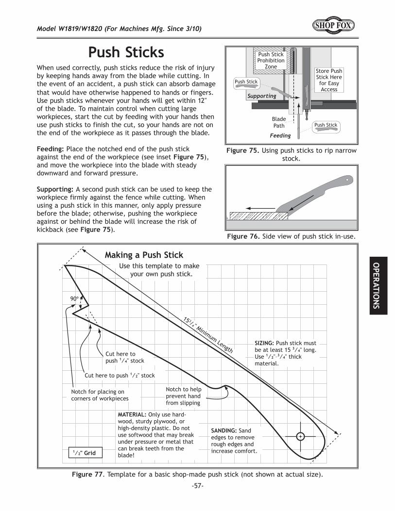
-57-
When used correctly, push sticks reduce the risk of injury by keeping hands away from the blade while cutting. In the event of an accident, a push stick can absorb damage that would have otherwise happened to hands or fingers.Use push sticks whenever your hands will get within 12" of the blade. To maintain control when cutting large workpieces, start the cut by feeding with your hands then use push sticks to finish the cut, so your hands are not on the end of the workpiece as it passes through the blade.
Place the notched end of the push stick against the end of the workpiece (see inset ), and move the workpiece into the blade with steady downward and forward pressure.
A second push stick can be used to keep the workpiece firmly against the fence while cutting. When using a push stick in this manner, only apply pressure before the blade; otherwise, pushing the workpiece against or behind the blade will increase the risk of kickback (see ).
90º
Cut here topush 1⁄4" stock
Cut here to push 1⁄2" stock
Notch for placing on corners of workpieces
15 3/4" Minimum Length
MATERIAL: Only use hard-wood, sturdy plywood, or high-density plastic. Do not use softwood that may break under pressure or metal that can break teeth from the blade!
SANDING: Sand edges to remove rough edges and increase comfort.
SIZING: Push stick must be at least 15 3⁄4" long. Use 1⁄2"–3⁄4" thick material.
Notch to help prevent hand from slipping
1⁄2" Grid
77. Template for a basic shop-made push stick (not shown at actual size).
Use this template to make your own push stick.
Side view of push stick in-use.
Feeding
Supporting
BladePath Push Stick
Push Stick
Push StickProhibition
ZoneStore Push Stick Here for Easy Access
Using push sticks to rip narrow stock.
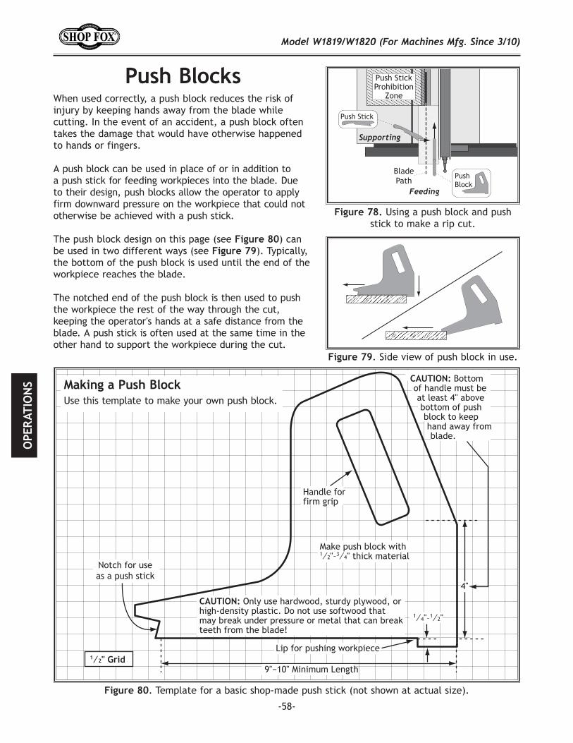
-58-
When used correctly, a push block reduces the risk of injury by keeping hands away from the blade while cutting. In the event of an accident, a push block often takes the damage that would have otherwise happened to hands or fingers.
A push block can be used in place of or in addition to a push stick for feeding workpieces into the blade. Due to their design, push blocks allow the operator to apply firm downward pressure on the workpiece that could not otherwise be achieved with a push stick.
The push block design on this page (see 80) can be used in two different ways (see 79). Typically, the bottom of the push block is used until the end of the workpiece reaches the blade.
The notched end of the push block is then used to push the workpiece the rest of the way through the cut, keeping the operator's hands at a safe distance from the blade. A push stick is often used at the same time in the other hand to support the workpiece during the cut.
. Side view of push block in use.
BladePath
Push Stick
PushBlock
Push StickProhibition
Zone
Feeding
Supporting
Using a push block and push stick to make a rip cut.
9"−10" Minimum Length
Lip for pushing workpiece
Handle for firm grip
Make push block with1⁄2"–3⁄4" thick material
1⁄4"–1⁄2"
4"
Notch for useas a push stick
1⁄2" Grid
CAUTION: Only use hardwood, sturdy plywood, or high-density plastic. Do not use softwood that may break under pressure or metal that can break teeth from the blade!
CAUTION: Bottom of handle must be at least 4" above bottom of push block to keep hand away from blade.
. Template for a basic shop-made push stick (not shown at actual size).
Use this template to make your own push block.
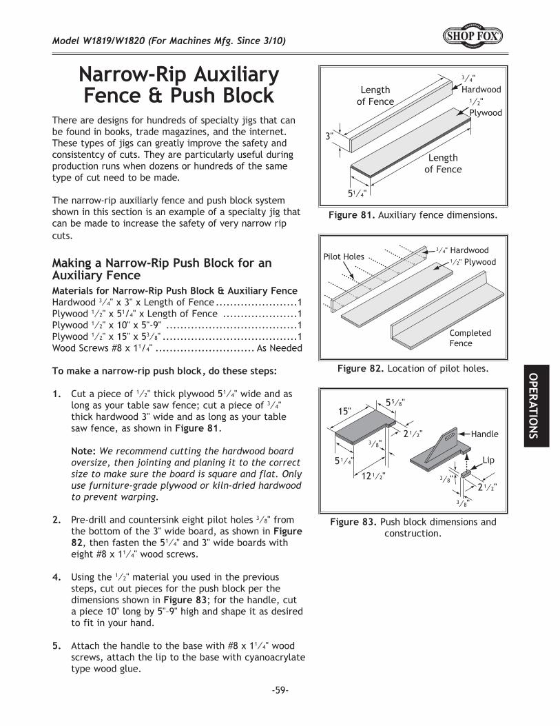
-59-
There are designs for hundreds of specialty jigs that can be found in books, trade magazines, and the internet. These types of jigs can greatly improve the safety and consistentcy of cuts. They are particularly useful during production runs when dozens or hundreds of the same type of cut need to be made.
The narrow-rip auxiliarly fence and push block system shown in this section is an example of a specialty jig that can be made to increase the safety of very narrow rip cuts.
Materials for Narrow-Rip Push Block & Auxiliary FenceHardwood 3⁄4" x 3" x Length of Fence .......................1Plywood 1⁄2" x 51/4" x Length of Fence .....................1 Plywood 1⁄2" x 10" x 5"-9" .....................................1Plywood 1⁄2" x 15" x 53⁄8" ......................................1Wood Screws #8 x 11/4" ............................ As Needed
Cut a piece of 1⁄2" thick plywood 5 1⁄4" wide and as long as your table saw fence; cut a piece of 3⁄4" thick hardwood 3" wide and as long as your table saw fence, as shown in .
Pre-drill and countersink eight pilot holes 3⁄8" from the bottom of the 3" wide board, as shown in 82, then fasten the 5 1⁄4" and 3" wide boards with eight #8 x 11⁄4" wood screws.
Using the 1⁄2" material you used in the previous steps, cut out pieces for the push block per the dimensions shown in ; for the handle, cut a piece 10" long by 5"–9" high and shape it as desired to fit in your hand.
Attach the handle to the base with #8 x 11⁄4" wood screws, attach the lip to the base with cyanoacrylate type wood glue.
3"
Lengthof Fence
Lengthof Fence
51⁄4"
3⁄4"Hardwood
1⁄2"Plywood
Auxiliary fence dimensions.
82 Location of pilot holes.
1⁄2" Plywood
CompletedFence
Pilot Holes3⁄4" Hardwood
5 5⁄8"
15"
5 1⁄4"
12 1⁄2"
2 1⁄2"
3⁄8"
Lip
Handle
3⁄8"
3⁄8"
2 1⁄2"
Push block dimensions and construction.
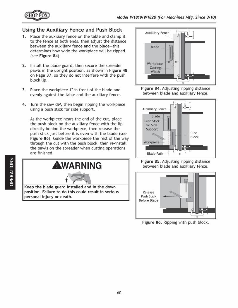
-60-
Place the auxiliary fence on the table and clamp it to the fence at both ends, then adjust the distance between the auxiliary fence and the blade—this determines how wide the workpiece will be ripped (see ).
Install the blade guard, then secure the spreader pawls in the upright position, as shown in Figure 48 on , so they do not interfere with the push block lip.
Place the workpiece 1" in front of the blade and evenly against the table and the auxiliary fence.
Turn the saw , then begin ripping the workpiece using a push stick for side support.
As the workpiece nears the end of the cut, place the push block on the auxiliary fence with the lip directly behind the workpiece, then release the push stick just before it is even with the blade (see
). Guide the workpiece the rest of the way through the cut with the push block, then re-install the pawls on the spreader when cutting operations are finished.
Workpiece CuttingWidth
Blade
Auxilliary Fence
84 Adjusting ripping distance between blade and auxiliary fence.
Auxilliary Fence
Blade
Workpiece
Push Stickfor Side Support
Blade Path
Push Block
Adjusting ripping distance between blade and auxiliary fence.
ReleasePush Stick
Before Blade
. Ripping with push block.
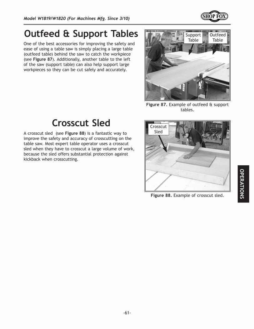
-61-
One of the best accessories for improving the safety and ease of using a table saw is simply placing a large table (outfeed table) behind the saw to catch the workpiece (see ). Additionally, another table to the left of the saw (support table) can also help support large workpieces so they can be cut safely and accurately.
A crosscut sled (see ) is a fantastic way to improve the safety and accuracy of crosscutting on the table saw. Most expert table operator uses a crosscut sled when they have to crosscut a large volume of work, because the sled offers substantial protection against kickback when crosscutting.
Example of outfeed & support tables.
Example of crosscut sled.
Crosscut Sled
Outfeed Table
Support Table
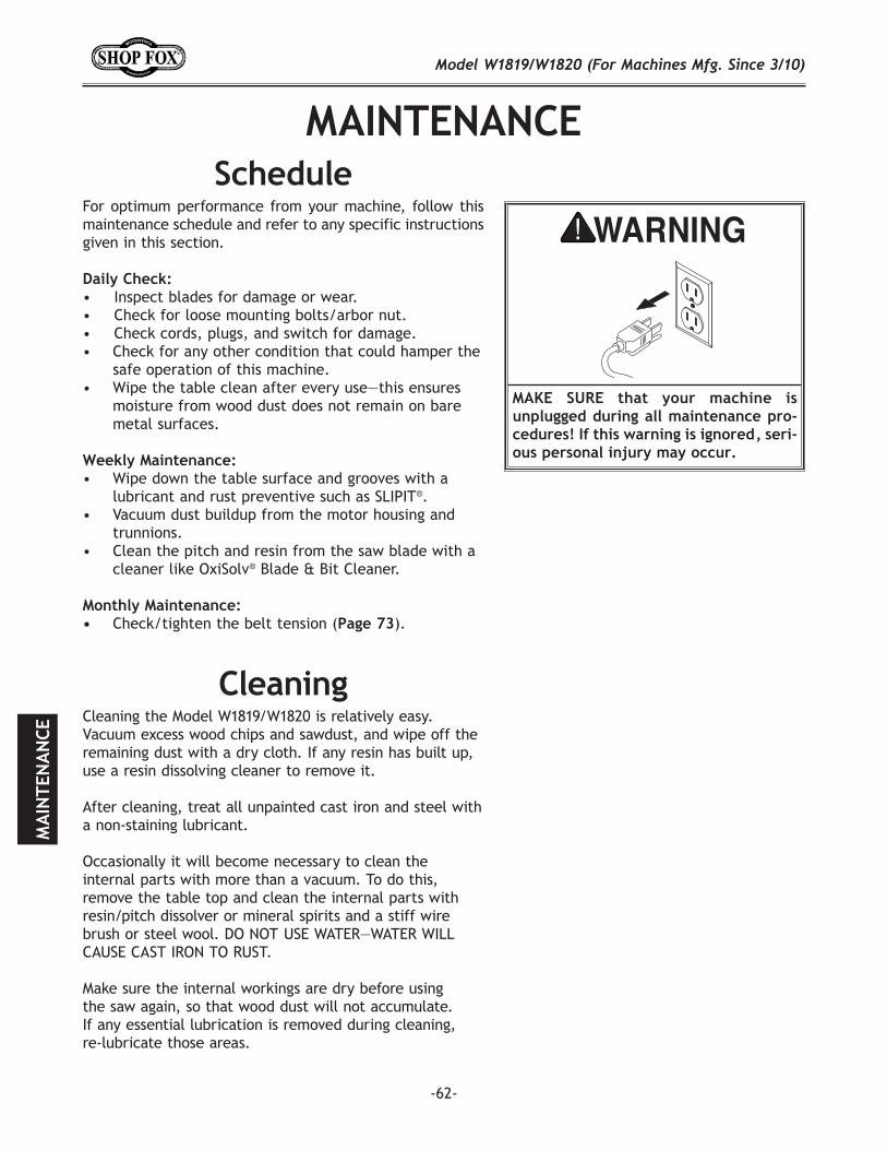
-62-
Cleaning the Model W1819/W1820 is relatively easy. Vacuum excess wood chips and sawdust, and wipe off the remaining dust with a dry cloth. If any resin has built up, use a resin dissolving cleaner to remove it.
After cleaning, treat all unpainted cast iron and steel with a non-staining lubricant.
Occasionally it will become necessary to clean the internal parts with more than a vacuum. To do this, remove the table top and clean the internal parts with resin/pitch dissolver or mineral spirits and a stiff wire brush or steel wool. DO NOT USE WATER—WATER WILL CAUSE CAST IRON TO RUST.
Make sure the internal workings are dry before using the saw again, so that wood dust will not accumulate. If any essential lubrication is removed during cleaning, re-lubricate those areas.
For optimum performance from your machine, follow this maintenance schedule and refer to any specific instructions given in this section.
• Inspect blades for damage or wear.• Check for loose mounting bolts/arbor nut.• Check cords, plugs, and switch for damage.• Check for any other condition that could hamper the
safe operation of this machine.• Wipe the table clean after every use—this ensures
moisture from wood dust does not remain on bare metal surfaces.
• Wipe down the table surface and grooves with a lubricant and rust preventive such as SLIPIT®.
• Vacuum dust buildup from the motor housing and trunnions.
• Clean the pitch and resin from the saw blade with a cleaner like OxiSolv® Blade & Bit Cleaner.
Check/tighten the belt tension ( ).
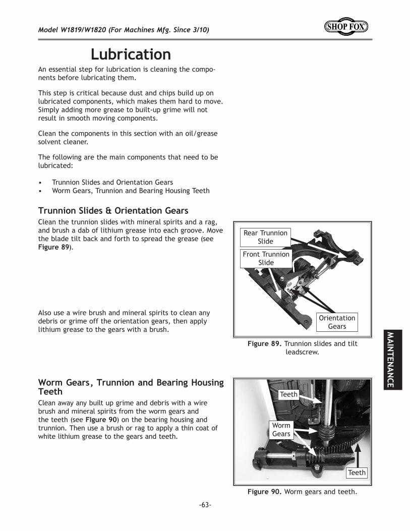
-63-
An essential step for lubrication is cleaning the compo-nents before lubricating them.
This step is critical because dust and chips build up on lubricated components, which makes them hard to move. Simply adding more grease to built-up grime will not result in smooth moving components.
Clean the components in this section with an oil/grease solvent cleaner.
The following are the main components that need to be lubricated:
• Trunnion Slides and Orientation Gears• Worm Gears, Trunnion and Bearing Housing Teeth
Clean the trunnion slides with mineral spirits and a rag, and brush a dab of lithium grease into each groove. Move the blade tilt back and forth to spread the grease (see
).
Also use a wire brush and mineral spirits to clean any debris or grime off the orientation gears, then apply lithium grease to the gears with a brush.
Trunnion slides and tilt leadscrew.
Rear Trunnion Slide
Front Trunnion Slide
Clean away any built up grime and debris with a wire brush and mineral spirits from the worm gears and the teeth (see 90) on the bearing housing and trunnion. Then use a brush or rag to apply a thin coat of white lithium grease to the gears and teeth.
Worm gears and teeth.
Worm Gears
Teeth
Teeth
Orientation Gears
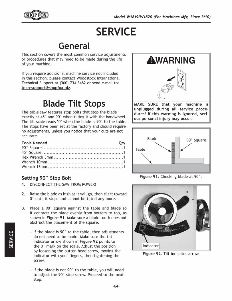
-64-
This section covers the most common service adjustments or procedures that may need to be made during the life of your machine.
If you require additional machine service not included in this section, please contact Woodstock International Technical Support at (360) 734-3482 or send e-mail to:
.
The table saw features stop bolts that stop the blade exactly at 45° and 90° when tilting it with the handwheel. The tilt scale reads "0" when the blade is 90° to the table. The stops have been set at the factory and should require no adjustments, unless you notice that your cuts are not accurate.
90 Square .......................................................145° Square .......................................................1Hex Wrench 3mm ...............................................1Wrench 10mm ...................................................1Wrench 13mm ...................................................1
DISCONNECT THE SAW FROM POWER!
Raise the blade as high as it will go, then tilt it toward 0° until it stops and cannot be tilted any more.
Place a 90° square against the table and blade so it contacts the blade evenly from bottom to top, as shown in . Make sure a blade tooth does not obstruct the placement of the square.
— If the blade is 90° to the table, then adjustments do not need to be made. Make sure the tilt indicator arrow shown in points to the 0° mark on the scale. Adjust the position by loosening the button head screw, moving the indicator with your fingers, then tightening the screw.
— If the blade is not 90° to the table, you will need to adjust the 90° stop screw. Proceed to the next step.
Checking blade at 90°.
. Tilt indicator arrow.
Indicator
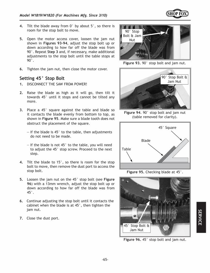
-65-
Tilt the blade away from 0° by about 5°, so there is room for the stop bolt to move.
Open the motor access cover, loosen the jam nut shown in , adjust the stop bolt up or down according to how far off the blade was from 90°. Repeat and, if necessary, make additional adjustments to the stop bolt until the table stops at 90°.
Tighten the jam nut, then close the motor cover.
90° stop bolt and jam nut.
90° Stop Bolt & Jam
Nut
. 90° stop bolt and jam nut (table removed for clarity).
90° Stop Bolt & Jam Nut
Checking blade at 45°.
DISCONNECT THE SAW FROM POWER!
Raise the blade as high as it will go, then tilt it towards 45° until it stops and cannot be tilted any more.
Place a 45° square against the table and blade so it contacts the blade evenly from bottom to top, as shown in . Make sure a blade tooth does not obstruct the placement of the square.
— If the blade is 45° to the table, then adjustments do not need to be made.
— If the blade is not 45° to the table, you will need to adjust the 45° stop screw. Proceed to the next step.
Tilt the blade to 15°, so there is room for the stop bolt to move, then remove the dust port to access the stop bolt.
Loosen the jam nut on the 45° stop bolt (see ) with a 13mm wrench, adjust the stop bolt up or
down according to how far off the blade was from 45°.
Continue adjusting the stop bolt until it contacts the cabinet when the blade is at 45°, then tighten the jam nut.
Close the dust port.
45° stop bolt and jam nut.
45° Stop Bolt & Jam Nut
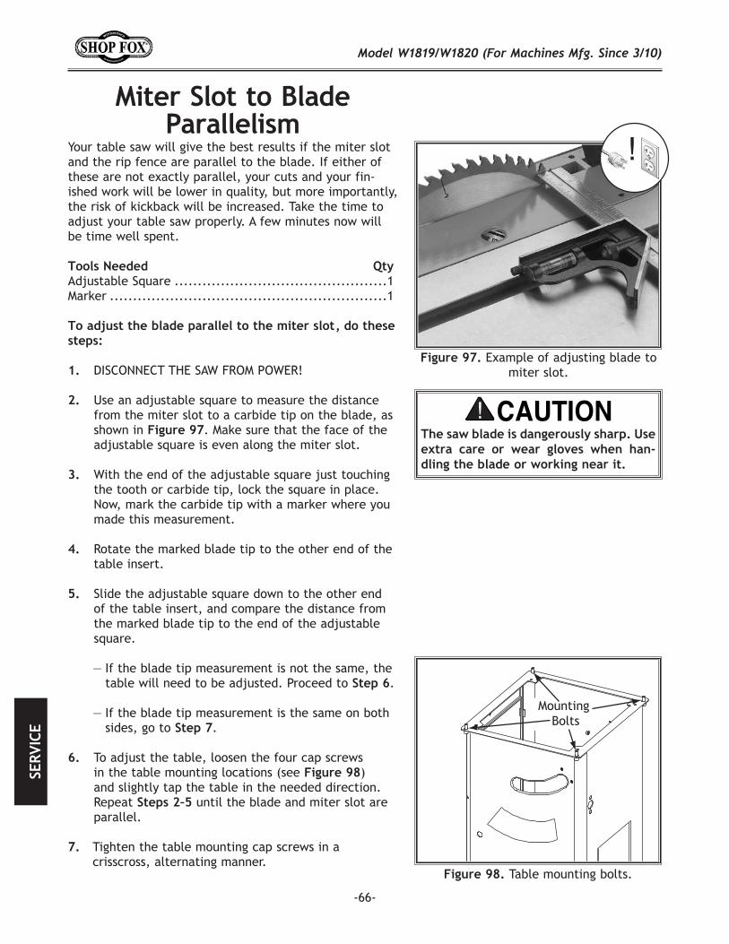
-66-
Figure 97. Example of adjusting blade to miter slot.
Your table saw will give the best results if the miter slot and the rip fence are parallel to the blade. If either of these are not exactly parallel, your cuts and your fin-ished work will be lower in quality, but more importantly, the risk of kickback will be increased. Take the time to adjust your table saw properly. A few minutes now will be time well spent.
Adjustable Square ..............................................1Marker ............................................................1
DISCONNECT THE SAW FROM POWER!
Use an adjustable square to measure the distance from the miter slot to a carbide tip on the blade, as shown in . Make sure that the face of the adjustable square is even along the miter slot.
With the end of the adjustable square just touching the tooth or carbide tip, lock the square in place. Now, mark the carbide tip with a marker where you made this measurement.
Rotate the marked blade tip to the other end of the table insert.
Slide the adjustable square down to the other end of the table insert, and compare the distance from the marked blade tip to the end of the adjustable square.
— If the blade tip measurement is not the same, the table will need to be adjusted. Proceed to .
— If the blade tip measurement is the same on both sides, go to .
To adjust the table, loosen the four cap screws in the table mounting locations (see ) and slightly tap the table in the needed direction. Repeat until the blade and miter slot are parallel.
Tighten the table mounting cap screws in a crisscross, alternating manner.
Figure 98. Table mounting bolts.
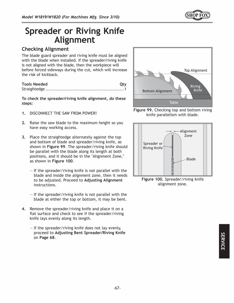
-67-
The blade guard spreader and riving knife must be aligned with the blade when installed. If the spreader/riving knife is not aligned with the blade, then the workpiece will before forced sideways during the cut, which will increase the risk of kickback.
Straightedge .....................................................1
DISCONNECT THE SAW FROM POWER!
Raise the saw blade to the maximum height so you have easy working access.
Place the straightedge alternately against the top and bottom of blade and spreader/riving knife, as shown in . The spreader/riving knife should be parallel with the blade along its length at both positions, and it should be in the "Alignment Zone," as shown in .
— If the spreader/riving knife is not parallel with the blade and inside the alignment zone, then it needs to be adjusted. Proceed to instructions.
— If the spreader/riving knife is not parallel with the blade at either the top or bottom, it may be bent.
Remove the spreader/riving knife and place it on a flat surface and check to see if the spreader/riving knife lays evenly along its length.
— If the spreader/riving knife does not lay evenly, proceed to on .
Spreader/riving knife alignment zone.
Checking top and bottom riving knife parallelism with blade.
Table
RivingKnife
Top Alignment
Bottom Alignment
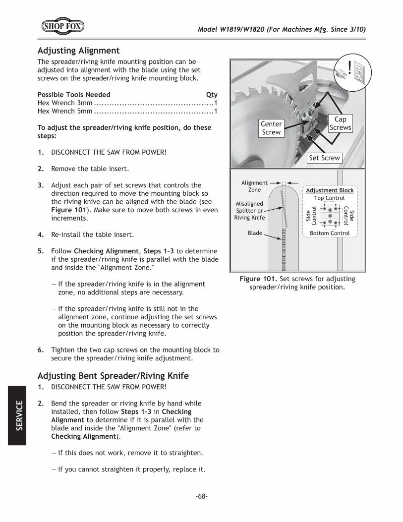
-68-
The spreader/riving knife mounting position can be adjusted into alignment with the blade using the set screws on the spreader/riving knife mounting block.
Hex Wrench 3mm ...............................................1Hex Wrench 5mm ...............................................1
To adjust the spreader/riving knife position, do these steps:
1. DISCONNECT THE SAW FROM POWER!
Remove the table insert.
Adjust each pair of set screws that controls the direction required to move the mounting block so the riving knive can be aligned with the blade (see
). Make sure to move both screws in even increments.
Re-install the table insert.
Follow , to determine if the spreader/riving knife is parallel with the blade and inside the "Alignment Zone."
— If the spreader/riving knife is in the alignment zone, no additional steps are necessary.
— If the spreader/riving knife is still not in the alignment zone, continue adjusting the set screws on the mounting block as necessary to correctly position the spreader/riving knife.
Tighten the two cap screws on the mounting block to secure the spreader/riving knife adjustment.
Cap Screws
Set Screw
Set screws for adjusting spreader/riving knife position.
Adjustment Block
Center Screw
Cap Screws
DISCONNECT THE SAW FROM POWER!
Bend the spreader or riving knife by hand while installed, then follow in
to determine if it is parallel with the blade and inside the "Alignment Zone" (refer to
).
— If this does not work, remove it to straighten.
— If you cannot straighten it properly, replace it.
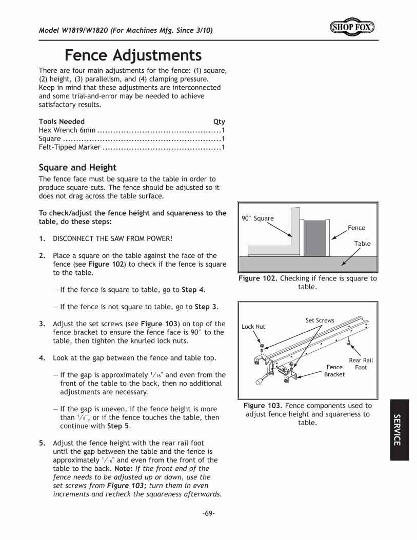
-69-
There are four main adjustments for the fence: (1) square, (2) height, (3) parallelism, and (4) clamping pressure. Keep in mind that these adjustments are interconnected and some trial-and-error may be needed to achieve satisfactory results.
Hex Wrench 6mm ...............................................1Square ............................................................1Felt-Tipped Marker .............................................1
The fence face must be square to the table in order to produce square cuts. The fence should be adjusted so it does not drag across the table surface.
DISCONNECT THE SAW FROM POWER!
Place a square on the table against the face of the fence (see ) to check if the fence is square to the table.
— If the fence is square to table, go to .
— If the fence is not square to table, go to .
Adjust the set screws (see ) on top of the fence bracket to ensure the fence face is 90° to the table, then tighten the knurled lock nuts.
Look at the gap between the fence and table top.
— If the gap is approximately 1⁄16" and even from the front of the table to the back, then no additional adjustments are necessary.
— If the gap is uneven, if the fence height is more than 1⁄8", or if the fence touches the table, then continue with .
Adjust the fence height with the rear rail foot until the gap between the table and the fence is approximately 1⁄16" and even from the front of the table to the back.
Checking if fence is square to table.
Fence components used to adjust fence height and squareness to
table.
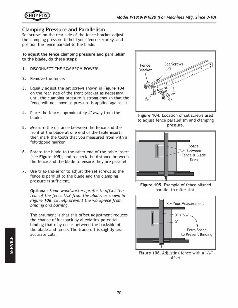
-70-
Clamping Pressure and ParallelismSet screws on the rear side of the fence bracket adjust the clamping pressure to hold your fence securely, and position the fence parallel to the blade.
DISCONNECT THE SAW FROM POWER!
Remove the fence.
Equally adjust the set screws shown in on the rear side of the front bracket as necessary until the clamping pressure is strong enough that the fence will not move as pressure is applied against it.
Location of set screws used to adjust fence parallelism and clamping
pressure.
Place the fence approximately 4" away from the blade.
Measure the distance between the fence and the front of the blade at one end of the table insert, then mark the tooth that you measured from with a felt-tipped marker.
Rotate the blade to the other end of the table insert (see ), and recheck the distance between the fence and the blade to ensure they are parallel.
Use trial-and-error to adjust the set screws so the fence is parallel to the blade and the clamping pressure is sufficient.
:
The argument is that this offset adjustment reduces the chance of kickback by alleviating potential binding that may occur between the backside of the blade and fence. The trade-off is slightly less accurate cuts.
. Example of fence aligned parallel to miter slot.
Adjusting fence with a 1⁄64" offset.
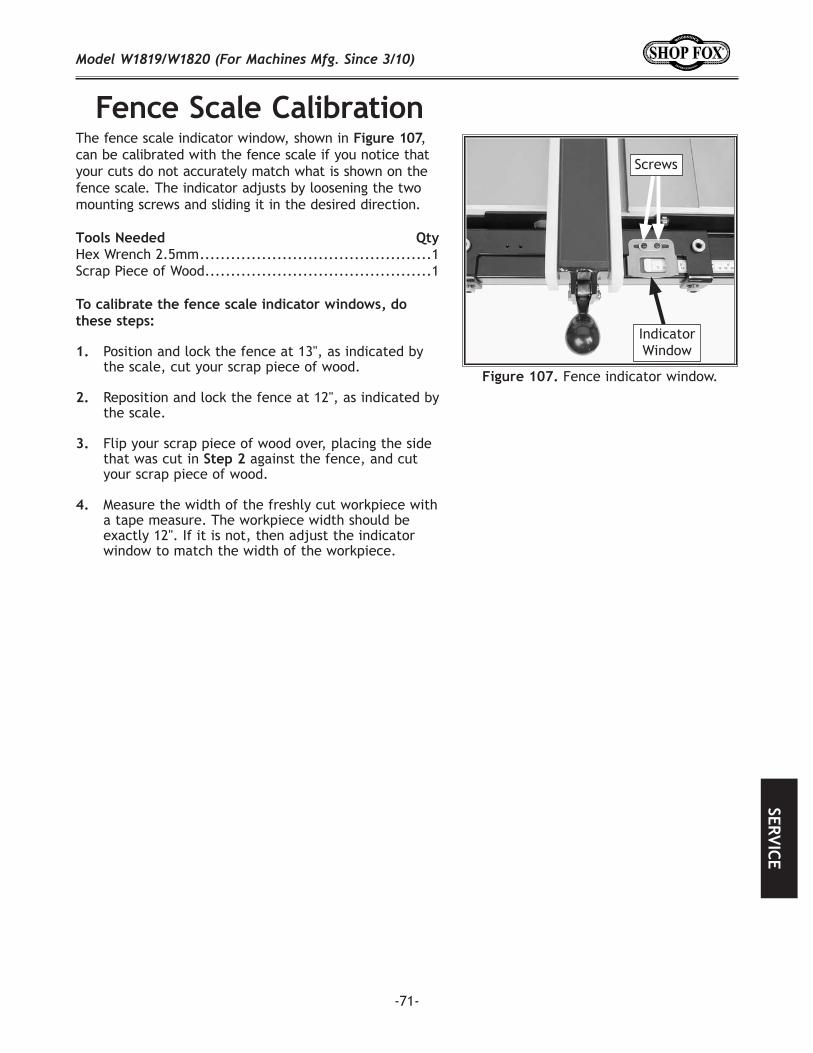
-71-
The fence scale indicator window, shown in , can be calibrated with the fence scale if you notice that your cuts do not accurately match what is shown on the fence scale. The indicator adjusts by loosening the two mounting screws and sliding it in the desired direction.
Hex Wrench 2.5mm .............................................1Scrap Piece of Wood ............................................1
Position and lock the fence at 13", as indicated by the scale, cut your scrap piece of wood.
Reposition and lock the fence at 12", as indicated by the scale.
Flip your scrap piece of wood over, placing the side that was cut in against the fence, and cut your scrap piece of wood.
Measure the width of the freshly cut workpiece with a tape measure. The workpiece width should be exactly 12". If it is not, then adjust the indicator window to match the width of the workpiece.
Fence indicator window.
Screws
Indicator Window
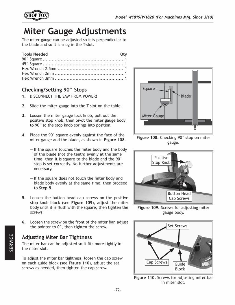
-72-
The miter gauge can be adjusted so it is perpendicular to the blade and so it is snug in the T-slot.
90° Square .......................................................145° Square .......................................................1Hex Wrench 2.5mm .............................................1Hex Wrench 2mm ...............................................1Hex Wrench 3mm ...............................................1
DISCONNECT THE SAW FROM POWER!
Slide the miter gauge into the T-slot on the table.
Loosen the miter gauge lock knob, pull out the positive stop knob, then pivot the miter gauge body to 90° so the stop knob springs into position.
Checking 90° stop on miter gauge.
Screws for adjusting miter gauge body.
Button Head Cap Screws
Positive Stop Knob
Loosen the button head cap screws on the positive stop knob block (see ), adjust the miter body until it is flush with the square, then tighten the screws.
Loosen the screw on the front of the miter bar, adjust the pointer to 0°, then tighten the screw.
Place the 90° square evenly against the face of the miter gauge and the blade, as shown in .
— If the square touches the miter body and the body of the blade (not the teeth) evenly at the same time, then it is square to the blade and the 90° stop is set correctly. No further adjustments are necessary.
— If the square does not touch the miter body and blade body evenly at the same time, then proceed to .
The miter bar can be adjusted so it fits more tightly in the miter slot.
To adjust the miter bar tightness, loosen the cap screw on each guide block (see ), adjust the set screws as needed, then tighten the cap screw.
Screws for adjusting miter bar in miter slot.
Set Screws
Cap Screws Guide Block
-73-
Wrenches 18mm .................................................2
DISCONNECT THE SAW FROM POWER!
Lower the blade completely, then open the motor cabinet.
Loosen the hex nuts on the motor shown in , and pivot the motor up and down to make sure
that it is movable.
Press down on the motor with one hand to keep the belt tension tight, then tighten the hex nuts.
Press each V-belt in the center to check the belt tension.
The belts are correctly tensioned when there is
approximately 1⁄2" deflection when they are pushed with moderate pressure, as shown in .
— If there is more than 1⁄2" deflection when the V-belts are pushed with moderate pressure, loosen the hex nuts, adjust the motor downward, then tighten the hex nuts.
Close the motor access cover.
DISCONNECT THE SAW FROM POWER!
Lower the blade completely, then open the motor access cover.
Loosen the hex nuts that secure the motor (see ) and raise the motor fully to remove
tension on the V-belts. Roll the V-belts off of the arbor and motor pulleys. Install a new matching set of V-belts onto the pulleys, lower the motor to tension the V-belts, then tighten the hex nuts.
Follow in the subsection to check V-belt tension, then close the motor cover.
The three V-belts stretch slightly as the saw is used. Most of the belt stretching will happen during the first 16 hours of use, but it may continue in small increments through continued use.
. Checking belt tension.
1⁄2"
Motor mounting nut.
V-Belts
Hex Nut(Not Shown)
Hex Nut
-74-
These pages are current at the time of printing. However, in the spirit of improvement, we may make changes to the electrical systems of future machines. Study this diagram carefully. If you notice differences between your machine and these wiring diagrams, call Woodstock International Technical Support at (360) 734-3482.
Working on wiring that is connected to a power source is extremely dangerous. Touching electrified parts will result in personal injury including but not limited to severe burns, electrocution, or death. Disconnect the power from the machine before servicing electrical components!
Due to the inherent hazards of electricity, only a qualified electrician should perform wiring tasks on this machine. If you are not a qualified electrician, get help from one before attempting any kind of wiring job.
All connections must be tight to prevent wires from loosening during machine operation. Double-check all wires disconnected or connected during any wiring task to ensure tight connections.
Damaged wires or components increase the risk of serious personal injury, fire, or machine damage. If you notice that any wires or components are damaged while performing a wiring task, replace those wires or components before completing the task.
The motor wiring shown in these diagrams is current at the time of printing, but it may not match your machine. Always use the wiring diagram inside the motor junction box.
Using aftermarket parts or modifying the wiring beyond what is shown in the diagram may lead to unpredictable results, including serious injury or fire.
Some capacitors and power inverters store an electrical charge for up to five minutes after being disconnected from the power source. To avoid being shocked, wait at least this long before working on these components.
You MUST follow the electrical requirements at the beginning of this manual when connecting your machine to a power source.
If you are experiencing difficulties understanding the information included in this section, contact our Technical Support at (360) 734-3482.
The photos and diagrams included in this section are best viewed in color. You can view these pages in color at www.shopfox.biz.
BLACK
WHITE
GREEN
RED
BLUE
BROWN
GRAY
ORANGE
YELLOWYELLOWGREENPURPLE
PINK
LIGHTBLUEBLUEWHITETUR-QUOISE
WIRING DIAGRAM COLOR KEY
-75-
ReadPage 74
Before Wiring
Start capacitor.
Run capacitor.
Magnetic switch.
Motor wiring.
-76-
This section covers the most common problems and corrections with this type of machine.
Symptom Possible Cause Possible SolutionMachine does not start or a breaker trips.
1. Locking pin installed.2. Blown fuse.3. Power supply switched OFF or at
fault.4. Plug/receptacle at fault/wired
wrong.5. Motor connection wired wrong.6. Wall circuit breaker tripped.7. Wiring open/has high resistance.8. Motor ON/OFF switch at fault.9. Start capacitor at fault.10. Motor at fault.
1. Remove locking pin from ON button.2. Replace fuse/ensure no shorts.3. Ensure power supply is on/has correct voltage.
4. Test for good contacts; correct the wiring.
5. Correct motor wiring connections.6. Ensure circuit size is correct/replace weak breaker.7. Check/fix broken, disconnected, or corroded wires. 8. Replace switch.9. Test/replace if faulty.10. Test/repair/replace.
Machine stalls or is under-powered.
1. Feed rate/cutting speed too fast.2. Workpiece material unsuitable for
machine.3. Workpiece crooked; fence mis-
adjusted.4. Machine undersized for task.
5. Run capacitor at fault.6. Belt slipping.7. Motor wired incorrectly.8. Plug/receptacle at fault.9. Pulley/sprocket slipping on shaft.10. Motor bearings at fault.11. Contactor not energized/has poor
contacts.12. Motor overheated.13. Motor at fault.
1. Decrease feed rate/cutting speed.2. Only cut wood/ensure moisture is below 20%.
3. Straighten or replace workpiece/adjust fence.
4. Use correct blade/reduce feed rate or depth of cut.
5. Test/repair/replace.6. Tension/replace belt (Page 73).7. Wire motor correctly.8. Test for good contacts/correct wiring.9. Replace loose pulley/shaft.10. Test/repair/replace.11. Test all legs for power/replace if faulty.
12. Clean motor, let cool, and reduce workload.13. Test/repair/replace.
Machine has vibration or noisy operation.
1. Motor or component loose.
2. Blade at fault.3. Belts worn or loose.4. Pulley loose.5. Motor mount loose/broken.6. Machine incorrectly mounted.7. Arbor pulley loose.8. Motor fan rubbing on fan cover.9. Arbor bearings at fault.10. Motor bearings at fault.
1. Inspect/replace damaged bolts/nuts, and re-tighten with thread locking fluid.
2. Replace warped/bent blade; resharpen dull blade.3. Tension/replace belts (Page 73).4. Realign/replace shaft, pulley, setscrew, and key.5. Tighten/replace.6. Tighten mounting bolts; relocate/shim machine.7. Retighten/replace arbor pulley.8. Fix/replace fan cover; replace loose/damaged fan.9. Replace arbor housing bearings; replace arbor. 10. Test by rotating shaft; grinding/loose shaft requires
bearing replacement.
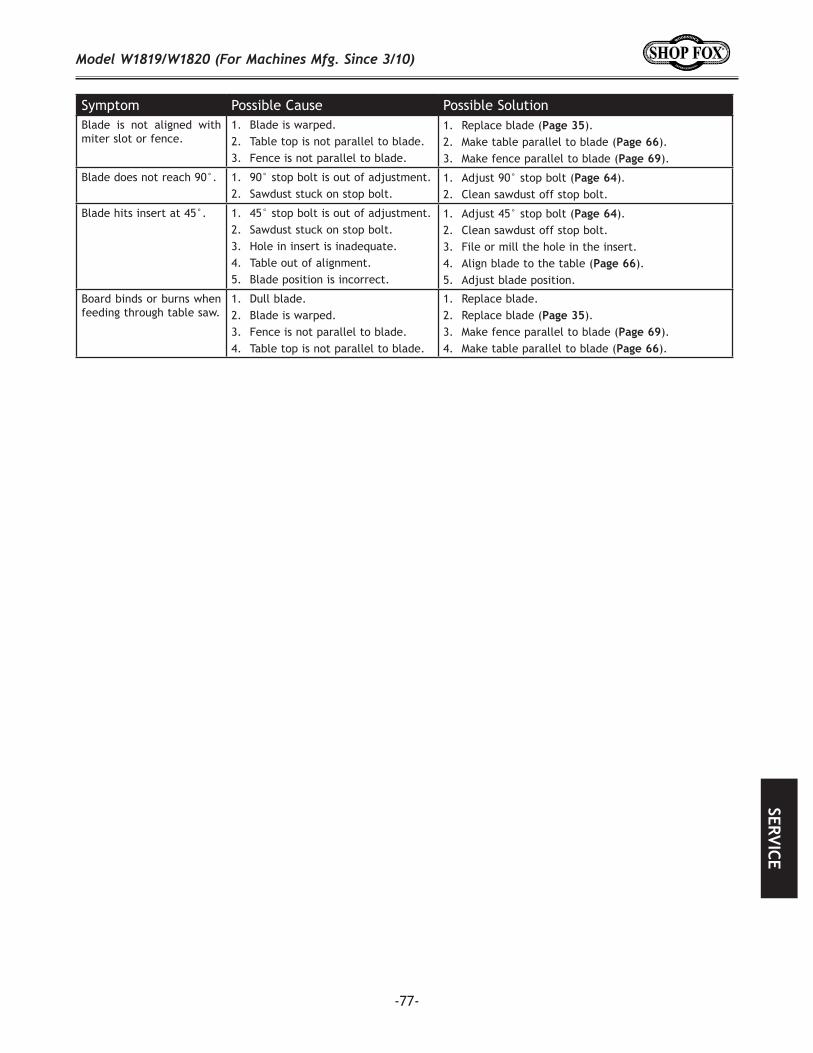
-77-
Symptom Possible Cause Possible SolutionBlade is not aligned with miter slot or fence.
1. Blade is warped.2. Table top is not parallel to blade.3. Fence is not parallel to blade.
1. Replace blade ( ).2. Make table parallel to blade ( ). 3. Make fence parallel to blade ( ).
Blade does not reach 90°. 1. 90° stop bolt is out of adjustment.2. Sawdust stuck on stop bolt.
1. Adjust 90° stop bolt ( ).2. Clean sawdust off stop bolt.
Blade hits insert at 45°. 1. 45° stop bolt is out of adjustment.2. Sawdust stuck on stop bolt.3. Hole in insert is inadequate.4. Table out of alignment.5. Blade position is incorrect.
1. Adjust 45° stop bolt ( ).2. Clean sawdust off stop bolt.3. File or mill the hole in the insert.4. Align blade to the table ( ). 5. Adjust blade position.
Board binds or burns when feeding through table saw.
1. Dull blade.2. Blade is warped.3. Fence is not parallel to blade.4. Table top is not parallel to blade.
1. Replace blade.2. Replace blade ( ).3. Make fence parallel to blade ( ). 4. Make table parallel to blade ( ).
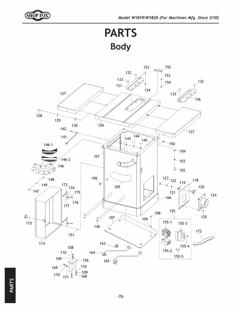
-78-
155
155-1
155-2
155-3
155-4
155-5
108
109
109
156
110
110
168
169
170171
101
102
103
104
105
106
107108
109
114
115
118119
120121
122123
124
125
126
127
127
128129
130
131
132
132133
133134
136
140
141
142
143144
145
146
146-1
146-2
147
148149
150
151
152153
153
154
164
163
172
166
165
173
177
174175
176

-79-
REF PART # DESCRIPTION REF PART # DESCRIPTION101 X1819101 CABINET STAND 144 XPLW06M LOCK WASHER 10MM102 XPCAP88M CAP SCREW M10-1.25 X 25 145 XPN02M HEX NUT M10-1.5103 XPLW06M LOCK WASHER 10MM 146 X1819146 DUST SHIELD104 XPW04M FLAT WASHER 10MM 146-1 X1819146-1 UPPER BRUSH105 X1819105 TILT SCALE 146-2 X1819146-2 LOWER BRUSH106 X1819106 STRAIN RELIEF 147 XPS02M PHLP HD SCR M4-.7 X 12107 X1819107 BASE PLATE 148 XPW05M FLAT WASHER 4MM108 XPS14M PHLP HD SCR M6-1 X 12 149 XPLW02M LOCK WASHER 4MM109 XPW03M FLAT WASHER 6MM 150 X1819150 HOOK110 XPLW03M LOCK WASHER 6MM 151 XPTLW13M INT TOOTH WASHER 6MM114 X1819114 MOTOR COVER 152 X1819152 LIMIT PLATE 115 X1819115 KNOB BOLT M6-1 153 XPN06M HEX NUT M5-.8118 X1819118 CLEAN-OUT DOOR 154 XPS06M PHLP HD SCR M5-.8 X 20119 X1819119 DOOR LATCH 155 X1819155 MAG SWITCH ASSEMBLY MS-15120 X1819120 KNOB BOLT M8-1.25 155-1 X1819155-1 CONTACTOR CHINT NC1-18121 XPW01M FLAT WASHER 8MM 155-2 X1819155-2 OL RELAY CHINT NR2-25 12-18122 XPLW04M LOCK WASHER 8MM 155-3 X1819155-3 SWITCH BOX FRONT/BACK123 XPN03M HEX NUT M8-1.25 155-4 X1819155-4 MAG SWITCH COVER SCREW124 X1819124 DUST HOOD 155-5 X1819155-5 ON/OFF SWITCH CHINT NP2125 XPS05M PHLP HD SCR M5-.8 X 8 156 X1819156 SWITCH BRACKET126 X1819126 TABLE 163 X1819163 STRAIN RELIEF127 X1819127 EXTENSION WING 164 X1819164 MOTOR CORD 14AWG 3C128 XPCAP13M CAP SCREW M8-1.25 X 30 165 X1819165 POWER CORD W/PLUG129 XPLW04M LOCK WASHER 8MM 166 X1819166 BLACK TRIM TAPE130 XPW01M FLAT WASHER 8MM 168 XPB02M HEX BOLT M6-1 X 12131 X1819131 STANDARD TABLE INSERT 169 XPBHS16M BUTTON HD CAP SCR M5-.8 X 16132 XPSS53M SET SCREW M5-.8 X 12 170 XPLW01M LOCK WASHER 5MM133 XPS08M PHLP HD SCR M5-.8 X 12 171 XPW02M FLAT WASHER 5MM134 XPS06M PHLP HD SCR M5-.8 X 20 172 X1819172 PUSH STICK136 X1819136 DADO TABLE INSERT 173 X1819173 UPPER HINGE BLOCK140 XPRIV004M STEEL BLIND RIVET 4 X 10MM 174 XPW02M FLAT WASHER 5MM141 X1819141 SHIPPING BRACE 175 XPLW01M LOCK WASHER 5MM142 XPB74M HEX BOLT M10-1.5 X 20 176 XPBHS06M BUTTON HD CAP SCR M5-.8 X 12143 XPW04M FLAT WASHER 10MM 177 X1819177 LOWER HINGE BLOCK
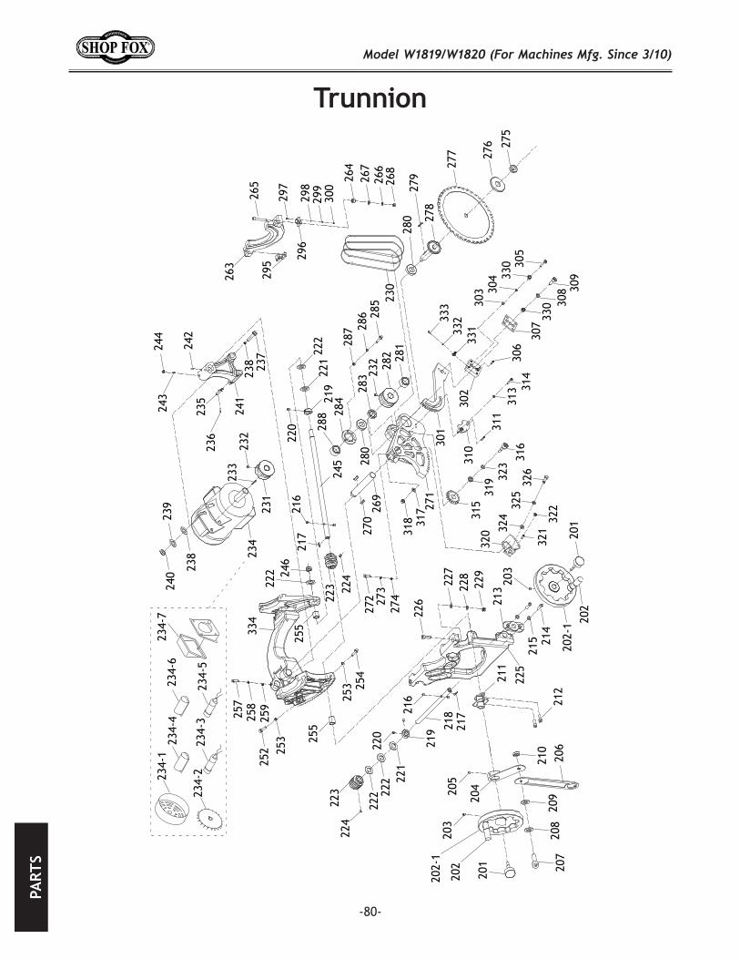
-80-
201
202
203
201
202
203
204205
206
207
208
209
210
211
212
213
214
215
216
216
217
217
218
219
219
220
220
221
221
222 22
2
222
222
223
223
224
224
225
226
227
228
229
230
231
232
232
233
234
234-1
234-2
234-3
234-4
234-5
234-6
234-7
235
236
237
238
238
239
240
241
242
243
244
245
246
252
253
253
254
255
255
257
258
259
263
264
265 26
626
7
268
269
270
271
272 273
274
275
276
277
278
279
280
280
281
282
283
284
285
286
287
288
295
296
297
298
299
300
301
302
303 30
4
305
306
307
308 30
9
310
311
313 31
4
315
316
317
318
319
320
32132
2
323
32432
532
6
330
330
33133233
3
334
202-1
202-1

-81-
REF PART # DESCRIPTION REF PART # DESCRIPTION201 X1819201 HANDWHEEL LOCK KNOB 242 XPSS14M SET SCREW M8-1.25 X 12202 X1819202 HANDWHEEL HANDLE 243 XPSS19M SET SCREW M8-1.25 X 30202-1 X1819202-1 HANDWHEEL 244 XPN03M HEX NUT M8-1.25203 XPSS53M SET SCREW M5-.8 X 12 245 X1819245 ELEVATION SHAFT204 X1819204 TILT POINTER PIVOT 246 XPLN14M LOCK NUT M18-1.5205 XPSS26M SET SCREW M5-.8 X 6 252 XPB09M HEX BOLT M8-1.25 X 20206 X1819206 TILT POINTER 253 XPN03M HEX NUT M8-1.25207 XPCAP25M CAP SCREW M6-1 X 12 254 XPB20M HEX BOLT M8-1.25 X 35208 XPLW03M LOCK WASHER 6MM 255 X1819255 SHAFT SLEEVE209 XPW03M FLAT WASHER 6MM 257 XPSS20M SET SCREW M8-1.25 X 8210 XPN01M HEX NUT M6-1 258 X1819258 COMPRESSION SPRING211 X1819211 TILT POINTER BRACKET 259 XPSTB002M STEEL BALL 8MM212 XPCAP38M CAP SCREW M5-.8 X 25 263 X1819263 REAR TRUNNION213 X1819213 TILT SHAFT BRACKET 264 X1819264 SPACER214 XPCAP31M CAP SCREW M8-1.25 X 25 265 XPCAP13M CAP SCREW M8-1.25 X 30215 XPLW04M LOCK WASHER 8MM 266 XPW01M FLAT WASHER 8MM216 X1819216 SHAFT PIN 267 XPLW04M LOCK WASHER 8MM217 XPK170M KEY 5 X 5 X 36 268 XPN03M HEX NUT M8-1.25218 X1819218 TILT SHAFT 269 X1819269 PIVOT SHAFT219 X1819219 LOCK COLLAR 270 XPK44M KEY 6 X 6 X 50220 XPSS03M SET SCREW M6-1 X 8 271 X1819271 PIVOT BRACKET221 XPLW12M LOCK WASHER 18MM 272 XPB116M HEX BOLT M10-1.5 X 45222 X1819222 COPPER WASHER 18MM 273 XPLW06M LOCK WASHER 10MM223 X1819223 WORM 274 XPW04M FLAT WASHER 10MM224 XPSS01M SET SCREW M6-1 X 10 275 X1819275 ARBOR NUT225 X1819225 FRONT TRUNNION 276 X1819276 ARBOR FLANGE226 XPCAP72M CAP SCREW M10-1.5 X 30 277 X1819277 BLADE 10" 40TPI 5/8" BORE227 XPW04M FLAT WASHER 10MM 278 X1819278 BLADE ARBOR228 XPLW06M LOCK WASHER 10MM 279 XPK12M KEY 5 X 5 X 30229 XPN02M HEX NUT M10-1.5 280 XP6005ZZ BALL BEARING 6005ZZ230 X1819230 BELT SPZ 625 281 X1819281 FRONT PULLEY SPACER231 X1819231 MOTOR PULLEY 282 X1819282 ARBOR PULLEY232 XPSS53M SET SCREW M5-.8 X 12 283 X1819283 REAR PULLEY SPACER233 XPK12M KEY 5 X 5 X 30 284 X1819284 FLANGE RING234 X1819234 MOTOR 3HP 220V 1PH 285 XPS08M PHLP HD SCR M5-.8 X 12234-1 X1819234-1 MOTOR FAN COVER 286 XPLW01M LOCK WASHER 5MM234-2 X1819234-2 MOTOR FAN 287 XPW02M FLAT WASHER 5MM234-3 X1819234-3 R CAPACITOR 25M 370V 1-3/4 X 3 288 XPLN15M LOCK NUT M16-1.5234-4 X1819234-4 R CAPACITOR COVER 295 X1819295 REAR TRUNNION BRACKET234-5 X1819234-5 S CAP 200M 250V 1-1/4 X 2-3/4 296 X1819296 FRONT TRUNNION BRACKET234-6 X1819234-6 S CAPACITOR COVER 297 XPCAP13M CAP SCREW M8-1.25 X 30234-7 X1819234-7 MOTOR JUNCTION BOX 298 XPW01M FLAT WASHER 8MM235 X1819235 ORIENTATION PIN 299 XPLW04M LOCK WASHER 8MM236 XPRP108M ROLL PIN 4 X 28 300 XPN03M HEX NUT M8-1.25237 XPB121M HEX BOLT M12-1.75 X 100 301 X1819301 BULL GEAR238 XPW06M FLAT WASHER 12MM 302 X1819302 SPLITTER ADJUSTMENT BLOCK239 XPLW05M LOCK WASHER 12MM 303 XPW03M FLAT WASHER 6MM240 XPN09M HEX NUT M12-1.75 304 XPLW03M LOCK WASHER 6MM241 X1819241 MOTOR FRAME SUPPORT 305 XPCAP06M CAP SCREW M6-1 X 25

-82-
REF PART # DESCRIPTION REF PART # DESCRIPTION306 XPSS04M SET SCREW M6-1 X 12 320 X1819320 PLATE GEAR307 X1819307 SPLITTER LOCK PLATE 321 XPSS25M SET SCREW M6-1 X 20308 XPLW03M LOCK WASHER 6MM 322 XPN01M HEX NUT M6-1309 XPB08M HEX BOLT M6-1 X 20 323 XPWF10M FENDER WASHER 10MM310 X1819310 ORIENTATION PLATE 324 XPW01M FLAT WASHER 8MM311 XPRP49M ROLL PIN 5 X 25 325 XPLW04M LOCK WASHER 8MM313 XPLW01M LOCK WASHER 5MM 326 XPCAP14M CAP SCREW M8-1.25 X 20314 XPCAP38M CAP SCREW M5-.8 X 25 330 X1819330 SPACER315 X1819315 GEAR 331 X1819331 POSITION PIN ASSEMBLY316 XPCAP47M CAP SCREW M10-1.5 X 40 332 XPLW02M LOCK WASHER 4MM317 XPW04M FLAT WASHER 10MM 333 XPSS22M SET SCREW M4-.7 X 12318 XPLN05M LOCK NUT M10-1.5 334 X1819334 MAIN TRUNNION319 X1819319 GEAR BUSHING
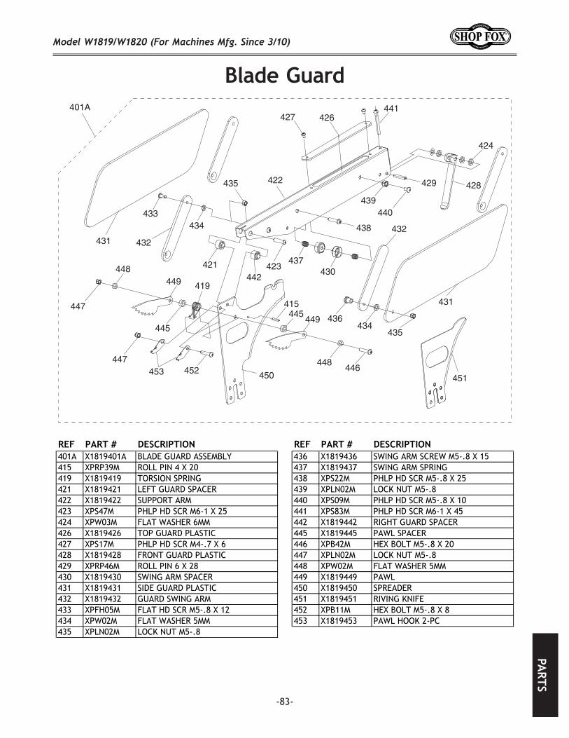
-83-
REF PART # DESCRIPTION REF PART # DESCRIPTION401A X1819401A BLADE GUARD ASSEMBLY 436 X1819436 SWING ARM SCREW M5-.8 X 15415 XPRP39M ROLL PIN 4 X 20 437 X1819437 SWING ARM SPRING419 X1819419 TORSION SPRING 438 XPS22M PHLP HD SCR M5-.8 X 25421 X1819421 LEFT GUARD SPACER 439 XPLN02M LOCK NUT M5-.8422 X1819422 SUPPORT ARM 440 XPS09M PHLP HD SCR M5-.8 X 10423 XPS47M PHLP HD SCR M6-1 X 25 441 XPS83M PHLP HD SCR M6-1 X 45424 XPW03M FLAT WASHER 6MM 442 X1819442 RIGHT GUARD SPACER426 X1819426 TOP GUARD PLASTIC 445 X1819445 PAWL SPACER427 XPS17M PHLP HD SCR M4-.7 X 6 446 XPB42M HEX BOLT M5-.8 X 20428 X1819428 FRONT GUARD PLASTIC 447 XPLN02M LOCK NUT M5-.8429 XPRP46M ROLL PIN 6 X 28 448 XPW02M FLAT WASHER 5MM430 X1819430 SWING ARM SPACER 449 X1819449 PAWL431 X1819431 SIDE GUARD PLASTIC 450 X1819450 SPREADER432 X1819432 GUARD SWING ARM 451 X1819451 RIVING KNIFE433 XPFH05M FLAT HD SCR M5-.8 X 12 452 XPB11M HEX BOLT M5-.8 X 8434 XPW02M FLAT WASHER 5MM 453 X1819453 PAWL HOOK 2-PC435 XPLN02M LOCK NUT M5-.8
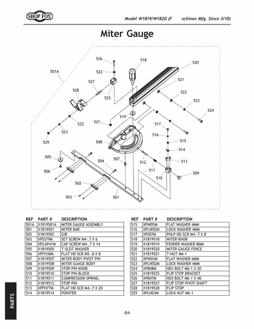
-84-
REF PART # DESCRIPTION REF PART # DESCRIPTION501A X1819501A MITER GAUGE ASSEMBLY 515 XPW05M FLAT WASHER 4MM501 X1819501 MITER BAR 516 XPLW02M LOCK WASHER 4MM502 X1819502 GIB 517 XPS07M PHLP HD SCR M4-.7 X 8503 XPSS79M SET SCREW M4-.7 X 6 518 X1819518 MITER KNOB504 XPCAP41M CAP SCREW M4-.7 X 14 519 X1819519 FENDER WASHER 8MM505 X1819505 T-SLOT WASHER 520 X1819520 MITER GAUGE FENCE506 XPFH30M FLAT HD SCR M5-.8 X 8 521 X1819521 T-NUT M6-1507 X1819507 MITER BODY PIVOT PIN 522 XPW03M FLAT WASHER 6MM508 X1819508 MITER GUAGE BODY 523 XPLW02M LOCK WASHER 4MM509 X1819509 STOP PIN KNOB 524 XPB08M HEX BOLT M6-1 X 20510 X1819510 STOP PIN BLOCK 525 X1819525 FLIP STOP BRACKET511 X1819511 COMPRESSION SPRING 526 XPB47M HEX BOLT M6-1 X 40512 X1819512 STOP PIN 527 X1819527 FLIP STOP PIVOT SHAFT513 XPFH77M FLAT HD SCR M4-.7 X 20 528 X1819528 FLIP STOP514 X1819514 POINTER 529 XPLN03M LOCK NUT M6-1
501A
501
502
503
504505
506
507
508
509510
511
512 513
514
515
516
517
518
519
520
521
522
523
524
525
526
527
528
529
522
522
523
521
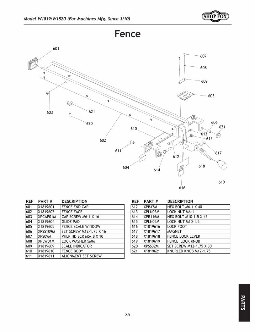
-85-
REF PART # DESCRIPTION REF PART # DESCRIPTION601 X1819601 FENCE END CAP 612 XPB47M HEX BOLT M6-1 X 40602 X1819602 FENCE FACE 613 XPLN03M LOCK NUT M6-1603 XPCAP01M CAP SCREW M6-1 X 16 614 XPB116M HEX BOLT M10-1.5 X 45604 X1819604 GLIDE PAD 615 XPLN05M LOCK NUT M10-1.5605 X1819605 FENCE SCALE WINDOW 616 X1819616 LOCK FOOT606 XPSS109M SET SCREW M12-1.75 X 16 617 X1819617 MAGNET607 XPS09M PHLP HD SCR M5-.8 X 10 618 X1819618 FENCE LOCK LEVER608 XPLW01M LOCK WASHER 5MM 619 X1819619 FENCE LOCK KNOB609 X1819609 SCALE INDICATOR 620 XPSS32M SET SCREW M12-1.75 X 30610 X1819610 FENCE BODY 621 X1819621 KNURLED KNOB M12-1.75611 X1819611 ALIGNMENT SET SCREW
601
602
603
604
605
606
607
608
609
611612
613
614
615
616
617
618
619
620
621
621610
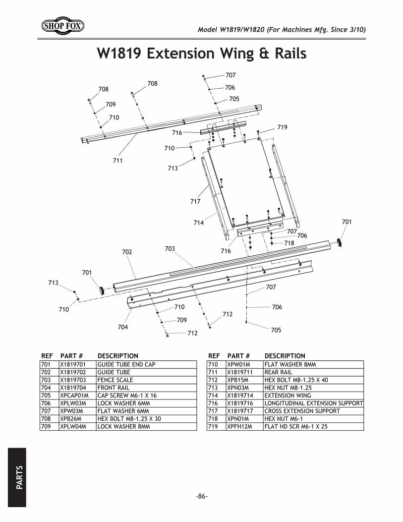
-86-
REF PART # DESCRIPTION REF PART # DESCRIPTION701 X1819701 GUIDE TUBE END CAP 710 XPW01M FLAT WASHER 8MM702 X1819702 GUIDE TUBE 711 X1819711 REAR RAIL703 X1819703 FENCE SCALE 712 XPB15M HEX BOLT M8-1.25 X 40704 X1819704 FRONT RAIL 713 XPN03M HEX NUT M8-1.25705 XPCAP01M CAP SCREW M6-1 X 16 714 X1819714 EXTENSION WING706 XPLW03M LOCK WASHER 6MM 716 X1819716 LONGITUDINAL EXTENSION SUPPORT707 XPW03M FLAT WASHER 6MM 717 X1819717 CROSS EXTENSION SUPPORT708 XPB26M HEX BOLT M8-1.25 X 30 718 XPN01M HEX NUT M6-1709 XPLW04M LOCK WASHER 8MM 719 XPFH12M FLAT HD SCR M6-1 X 25
701
702 703
704 705
706707
708
709
710
711
712
713
714
716
717
718
719
716
710
713
710
701
709
710 706
707
708
705
706
707
712
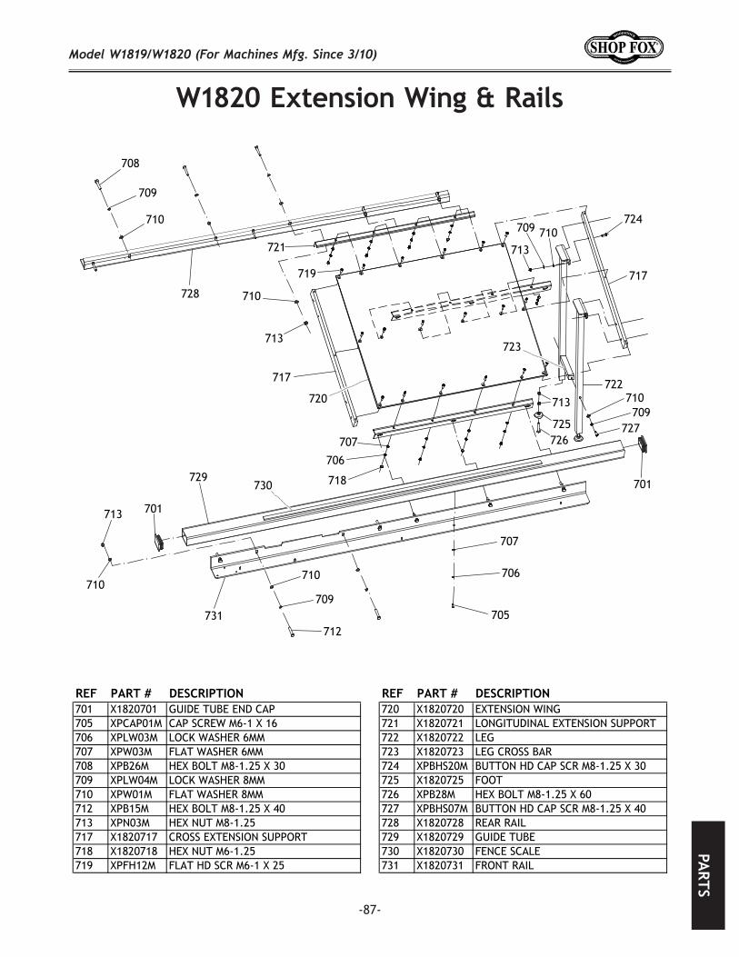
-87-
REF PART # DESCRIPTION REF PART # DESCRIPTION701 X1820701 GUIDE TUBE END CAP 720 X1820720 EXTENSION WING705 XPCAP01M CAP SCREW M6-1 X 16 721 X1820721 LONGITUDINAL EXTENSION SUPPORT706 XPLW03M LOCK WASHER 6MM 722 X1820722 LEG707 XPW03M FLAT WASHER 6MM 723 X1820723 LEG CROSS BAR708 XPB26M HEX BOLT M8-1.25 X 30 724 XPBHS20M BUTTON HD CAP SCR M8-1.25 X 30709 XPLW04M LOCK WASHER 8MM 725 X1820725 FOOT710 XPW01M FLAT WASHER 8MM 726 XPB28M HEX BOLT M8-1.25 X 60712 XPB15M HEX BOLT M8-1.25 X 40 727 XPBHS07M BUTTON HD CAP SCR M8-1.25 X 40713 XPN03M HEX NUT M8-1.25 728 X1820728 REAR RAIL717 X1820717 CROSS EXTENSION SUPPORT 729 X1820729 GUIDE TUBE718 X1820718 HEX NUT M6-1.25 730 X1820730 FENCE SCALE719 XPFH12M FLAT HD SCR M6-1 X 25 731 X1820731 FRONT RAIL
701
705
706
707
708
709
710
712
713
717
718
719
720
721
722
723
724
725726
727
728
729730
731
710
710709
713
717
710709
713
706
707
710
709
713
710
701
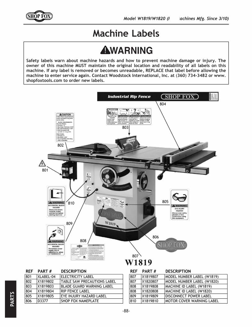
-88-
( )
REF PART # DESCRIPTION REF PART # DESCRIPTION801 XLABEL-04 ELECTRICITY LABEL 807 X1819807 MODEL NUMBER LABEL (W1819)802 X1819802 TABLE SAW PRECAUTIONS LABEL 807 X1820807 MODEL NUMBER LABEL (W1820)803 X1819803 BLADE GUARD WARNING LABEL 808 X1819808 MACHINE ID LABEL (W1819)804 X1819804 RIP FENCE LABEL 808 X1820808 MACHINE ID LABEL (W1820)805 X1819805 EYE INJURY HAZARD LABEL 809 X1819809 DISCONNECT POWER LABEL806 D3377 SHOP FOX NAMEPLATE 810 X1819810 MOTOR COVER WARNING LABEL
801
802
803
804
805
806
807
808
809
810

-89-

-90-


TAPE ALONG EDGES--PLEASE DO NOT STAPLE
FOLD ALONG DOTTED LINE
FOLD ALONG DOTTED LINE
PlaceStampHere