Embed Size (px)
Citation preview

C500-IDS01-V1/IDS02ID Sensor
Revised May 1990
Writte n and Produc ed for OMRON by:Brent WinchesterKoji SuzutaDATEC Inc.

�
Notice:OMRON products are manufactured for use according to proper procedures by a qualified operatorand only for the purposes described in this manual.
The following conventions are used to indicate and classify warnings in this manual. Always heed theinformation provided with them.
Indicates information that, if not heeded, could result in loss of life or seriousinjury.
Indicates information that, if not heeded, could result in minor injury or dam-age to the product.
OMRON Product ReferencesAll OMRON products are capitalized in this manual. The word “Unit” is also capitalized when it refersto an OMRON product, regardless of whether or not it appears in the proper name of the product.
The abbreviation “Ch,” which appears in some displays and on some OMRON products, means“word” and is abbreviated “Wd” in documentation.
Visual AidsThe following headings appear in the left column of the manual to help you locate different types ofinformation.
Indicates information of particular interest for efficient and convenient opera-tion of the product.
Indicates lists of one sort or another, such as procedures, precautions, etc.
OMRON, 1990��� ������ ����� � ���� �� ���� ����������� ��� � ��������� ����� �� � ������ ������ �� ����������� �� ���
����� �� �� ��� ����� ���������� ��������� ������������� ��������� �� �������� ������� �� ����� ������ ������
���� �� ���� �
� ����� ��������� �� ������ ���� ����� �� �� �� �� �� ����������� �������� ����� ������ ����� ���� ��
���������� ������� �� ����� ��� ������������� ��������� �� ����������� �������� �� ���� ������ �� ������ �� �����
������� ������ �� ��������� ��� �� ��!� �� �� ���������� �� ���� ������� ������� ���� ������ ��
������������� ��� ����� �� ���������� ���� �� ��� ��������� ������ ��� ������ �������� ���� �� �� �� �� ��������
���� �������� �� ���� ������������
DANGER!
Caution
Note
1, 2, 3...
���
����� � �������
��� �� �
������ ����������� ��� ����������� �� � � � � � � � � � � � � � � � ����� ������ ���� ���� �� � � � � � � � � � � � � � � � � � � � � � � � � � � � � � � � � � � � � � � � � � � � � � � � � � � � � � �
���� �������� �� � � � � � � � � � � � � � � � � � � � � � � � � � � � � � � � � � � � � � � � � � � � � � � � � � � � � � � � � � � � � � � �
���� ��� ������ ��� ��������� �� � � � � � � � � � � � � � � � � � � � � � � � � � � � � � � � � � � � � � � � � � � � � � � � �
���� ������ �������������� �� � � � � � � � � � � � � � � � � � � � � � � � � � � � � � � � � � � � � � � � � � � � � � � � � � � � �
���� ������������ �� � � � � � � � � � � � � � � � � � � � � � � � � � � � � � � � � � � � � � � � � � � � � � � � � � � � � � � � � � � � � �
��� �� �
��������� ��� � � � � � � � � � � � � � � � � � � � � � � � � � � � � � � � � � � � � � ����� � �!��" ������� �#� � � � � � � � � � � � � � � � � � � � � � � � � � � � � � � � � � � � � � � � � � � � � � � � � � � � � � � �
���� $"� %��� ������ �&� � � � � � � � � � � � � � � � � � � � � � � � � � � � � � � � � � � � � � � � � � � � � � � � � � � � � � � �
��� ��
!��"������" # � � � � � � � � � � � � � � � � � � � � � � � � � � � � � � � � � � � ����� ������ '(�� ��� )$!��*��� +���, ��� � � � � � � � � � � � � � � � � � � � � � � � � � � � � � � � � � � � � � � �
���� ������ '(�� ��� )�����*��� +���, �-� � � � � � � � � � � � � � � � � � � � � � � � � � � � � � � � � � � � � � � �
���� +��������� ��� � � � � � � � � � � � � � � � � � � � � � � � � � � � � � � � � � � � � � � � � � � � � � � � � � � � � � � � � � � � � �
���� $����� �������������� ��� � � � � � � � � � � � � � � � � � � � � � � � � � � � � � � � � � � � � � � � � � � � � � � � � � � � �
��� �� #
���$%���&�����" '(� � � � � � � � � � � � � � � � � � � � � � � � � � � � � � � � � ����� ������ +��������� &-� � � � � � � � � � � � � � � � � � � � � � � � � � � � � � � � � � � � � � � � � � � � � � � � � � � � � �
���� *"�� $� � �� � +��������� .��� &-� � � � � � � � � � � � � � � � � � � � � � � � � � � � � � � � � � � � � � � � � �
���� �������� ���! �"���� &�� � � � � � � � � � � � � � � � � � � � � � � � � � � � � � � � � � � � � � � � � � � � � � � � � � � �
����������/ �������� +����� &�� � � � � � � � � � � � � � � � � � � � � � � � � � � � � � � � � � � � � � � � � � � � � � � � � � � � � � � � � � � � �
0 � ���������� &�� � � � � � � � � � � � � � � � � � � � � � � � � � � � � � � � � � � � � � � � � � � � � � � � � � � � � � � � � � � � � � �
� /���� ���1������� �-�� � � � � � � � � � � � � � � � � � � � � � � � � � � � � � � � � � � � � � � � � � � � � � � � � � � � � � � � � � �
)������� �* � � � � � � � � � � � � � � � � � � � � � � � � � � � � � � � � � � � � � � � �
���+ �*�� � � � � � � � � � � � � � � � � � � � � � � � � � � � � � � � � � � � � � � � � � �
�,-�� ����� �..���� ���� � � � � � � � � � � � � � � � � � � � � � � � � � � � �
-������� /������ �� � � � � � � � � � � � � � � � � � � � � � � � � � � � � � � � � �

�+
About this Manual:
This manual explains the installation and operation of the C500-IDS01-V1 and C500-IDS02 ID Sen-sors, which are non-contact information detection systems with long-range detection capabilities.Through a Read/Write Head, the systems read information from or write information to a Data Carriermounted to a moving workpiece.
Before operating the ID Sensor, thoroughly familiarize yourself with both the Unit and this manual.
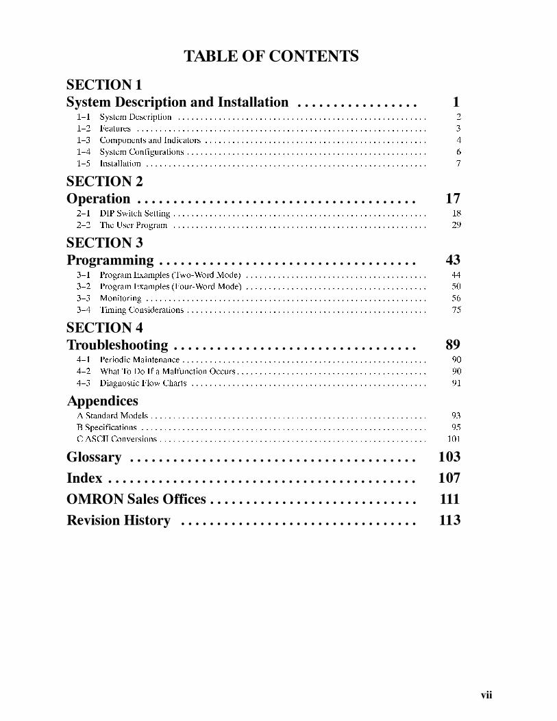
This manual is organized as follows:
Sect ion 1 describes the features, components, configuration, and installation of both models.
Sect ion 2 contains information on operation, including switch settings, bit allocation, and communica-tion commands, and introduces the user program.
Sect ion 3 describes programming and includes example programs that illustrate data transfer be-tween the Unit and the CPU; monitoring functions and timing considerations are also covered in thissection.
Sect ion 4 contains information on maintenance and troubleshooting.
Appendixes A, B, and C, a Glossary , and an Index are also provided.

�
��� �� �
������ ����������� ��� �����������
$"�� ������ �����2�� �"� ��������3 �� ������3 ������������3 ��� ������������ �� �"� ��--���-��4�5��-� � ������
��������
���� ������ ���� ���� �� � � � � � � � � � � � � � � � � � � � � � � � � � � � � � � � � � � � � � � � � � � � � � � � � � � � � � �
���� �������� �� � � � � � � � � � � � � � � � � � � � � � � � � � � � � � � � � � � � � � � � � � � � � � � � � � � � � � � � � � � � � � � �
���� ��� ������ ��� ��������� �� � � � � � � � � � � � � � � � � � � � � � � � � � � � � � � � � � � � � � � � � � � � � � � � �
���� ������ �������������� �� � � � � � � � � � � � � � � � � � � � � � � � � � � � � � � � � � � � � � � � � � � � � � � � � � � � �
���� ������������ �� � � � � � � � � � � � � � � � � � � � � � � � � � � � � � � � � � � � � � � � � � � � � � � � � � � � � � � � � � � � � �
������� ���������� �"� 65* 7��� ��� ��� ������� �� � � � � � � � � � � � � � � � � � � � � � � � � � � � � � �
������� ������ ��������� �-� � � � � � � � � � � � � � � � � � � � � � � � � � � � � � � � � � � � � � � � � � � � � � � �

�
1--1 System DescriptionThe ID Sensor system is a versatile non-contact identification system. A ba-sic ID Sensor system comprises an ID Sensor Unit, a Read/Write (R/W)Head, and a Data Carrier.
The ID Sensor Unit mounts to the OMRON C500, C1000H, or C2000H buil-ding-block type Programmable Controllers (PC). The Data Carrier mounts toa moving workpiece or workpiece carrier. The R/W Head, connected by cableto the ID Sensor Unit, must be positioned at a point within communicationrange of the Data Carrier’s travel path. Responding to commands from theuser program in the PC, the ID Sensor reads from or writes to the Data Carri-er through a R/W Head via electromagnetic induction. The operations of theID Sensor Unit can be monitored and checked with the Handheld Program-ming Console (C200H-PRO27-E).
Figure F1--1 illustrates the C500-IDS01-V1 ID Sensor system.
C500-IDS01-V1 ID Sensor System
ID Sensor UnitC500-IDS01-V1
Handheld Programming ConsoleC200H-PRO27-E
R/W HeadV600-H06
Data CarrierV600-D2KR01
F1--1 C500-IDS01-V1 ID Sensor System
When the R/W Head must be located more than 10 meters from the ID Sen-sor Unit, the C500-IDS02, a special long-range ID Sensor system is required.The long-range system includes an ID Adapter Unit that amplifies the signalbetween the R/W Head and ID Sensor Unit. An ID Adapter Unit can only beconnected to an ID Sensor Unit that is designed for that particular Adaptermodel.
Figure F1--2 illustrates the C500-IDS02 long-range ID Sensor system.
Long-range ID SensorSystem
������ ������� Section 1--1

ID Sensor UnitC500-IDS02
Handheld Programming ConsoleC200H-PRO27-E
R/W HeadV600-H06
Data CarrierV600-D2KR01
ID AdapterC500-IDA02
F1--2 C500-IDS02 ID Sensor System
1--2 FeaturesThe ID Sensor system has the following features:
Up to 251 words of data can be transferred between the PC and the ID Sen-sor Unit using Intelligent I/O Write (WRIT(87)) and Intelligent I/O Read(READ(88)) instructions, thus enabling high-speed data transfer.
Six Dedicated Commands Data is transferred between the ID Sensor Unit and the Data Carrier with thefollowing six dedicated commands:
ReadWriteAuto ReadAuto WriteClear-allAuto Read/Write Abort
Up to 502 bytes of data can be read from or written to the Data Carrier at onetime. Clear-all clears all data in the Data Carrier’s memory (2K bytes). Thesecommands are compatible with both the V600 and V620 ID Controllers.
The Handheld Programming Console can be used to monitor data transfer aswell as errors that have occurred during operation. A keyboard sheet for theHandheld Programming Console is included with the ID Sensor Unit.
Storage of Error Information Error information is stored in the internal memory of the ID Sensor Unit. Abuilt-in capacitor stores the information for 15 days (at 258C).
Compatibility The R/W Head and Data Carrier, for the C500-IDS01-V1 and C500-IDS02are compatible with the V600 ID Controller.
The C500-IDA02 ID Adapter for the C500-IDS02 is compatible with the V600ID Controller.
Intelligent I/O Read/WriteCapability
Monitoring with theHandheld ProgrammingConsole
������� Section 1--2

#
If an incompatible R/W Head, Data Carrier, or Adapter is connected to an IDSensor Unit, a connection error will occur, preventing operation of the Unit.
1--3 Components and IndicatorsFigure F1--3 shows the front panel of the C500-IDS01-V1 ID Sensor Unit.
Front PanelC500-IDS01-V1 ID Sensor Unit
24 VDC Power Supply terminals
Indicators
RESET switch(see note 2)
Handheld Programming Console con-nector
R/W Head connector
Unused
F1--3 C500-IDS01-V1/IDS21 ID Sensor Units
DIP switch(Behind indicator panel; see note 1)
1, 2, 3... 1. To gain access to the DIP switches, remove the indicator panel with astandard screwdriver.
2. Do not press RESET when the T/R indicator is lit. Refer to p NO TAGnote 2 before using the RESET switch.
Figure F1--4 shows the front panel of the C500-IDS02 ID Sensor Unit.
����� � �� � � � ������ Section 1--3

0
Front PanelC500-IDS02 ID Sensor Unit
Indicators
24 VDC Power Supply terminals
RESET switch(see note 2)
Handheld Programming Console connector
ID Adapter connector(RS-485)
Unused
F1--4 C500-IDS02 ID Sensor Unit
DIP switch(Behind indicator panel; see note 1)
Note 1. To gain access to the DIP switches, remove the indicator panel with astandard screwdriver.
2. Do not press RESET when the T/R indicator is lit. Refer to p NO TAG note2 before using the RESET switch.
Indicators Table T1--1 shows the functions of the ID Sensor Unit indicators.
T1--1 ID Sensor Unit Indicators
Indicator Function
RUN Lit while the ID Sensor is operating
Unlit when an error occurs in the ID Sensor Unit
T/R Lit during data communication
ERROR Lit when an error occurs in the ID Sensor Unit
4 CH(see p V)
Lit when the ID Sensor Unit is set to 4 words
Unlit when the ID Sensor Unit is set to 2 words
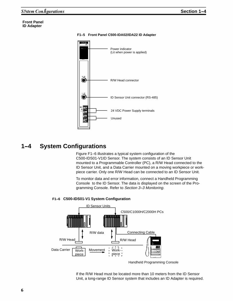
Figure F1--5 shows the front panel of the C500-IDA02 ID Adapter.
����� � �� � � � ������ Section 1--3
1
Front PanelID Adapter
F1--5 Front Panel C500-IDA02/IDA22 ID Adapter
24 VDC Power Supply terminals
Power indicator(Lit when power is applied)
R/W Head connector
ID Sensor Unit connector (RS-485)
Unused
1--4 System ConfigurationsFigure F1--6 illustrates a typical system configuration of theC500-IDS01-V1ID Sensor. The system consists of an ID Sensor Unitmounted to a Programmable Controller (PC), a R/W Head connected to theID Sensor Unit, and a Data Carrier mounted on a moving workpiece or work-piece carrier. Only one R/W Head can be connected to an ID Sensor Unit.
To monitor data and error information, connect a Handheld ProgrammingConsole to the ID Sensor. The data is displayed on the screen of the Pro-gramming Console. Refer to Section 3--3 Monitoring.
ID Sensor Units
C500/C1000H/C2000H PCs
Connecting Cable
R/W Head
R/W data
Data Carrier Work-piece
Movement Work-piece
Handheld Programming Console
R/W Head
F1--6 C500-IDS01-V1 System Configuration
If the R/W Head must be located more than 10 meters from the ID SensorUnit, a long-range ID Sensor system that includes an ID Adapter is required.
������ �� ������ � Section 1--4

�
The ID Adapter amplifies the signal between the R/W Head and ID SensorUnit.
Figure F1--7 illustrates the C500-IDS02 ID Sensor system.
ID Sensor Units
C500/C1000H/C2000H PCs
Connecting Cable
R/W Head
R/W data
Data Carrier Work-piece
Movement Work-piece
Handheld Programming Console
R/W Head
F1--7 C500-IDS02 System Configuration
ID Adapter Units
1--5 InstallationThis section contains information on the installation of system components.Before carrying out any of the procedures outlined in this section, make surethat they apply to your model of ID Sensor.
1--5--1 Installing the R/W Head and Data CarrierTo ensure correct communication between the ID Sensor Unit and the DataCarrier, install the R/W Head and Data Carrier according to the guidelines inthis section. Pay particular attention to the center displacement and the dis-tance between the Data Carrier and the R/W Head, as these parameters dif-fer depending on whether the R/W Head is detecting a stationary or movingData Carrier. The speed of the Data Carrier also affects the amount of datathat can be transmitted; high speeds reduce the amount of time the DataCarrier is within range of the R/W Head, thus reducing the amount of datathat can be transmitted.
The Data Carrier can be mounted directly to a moving workpiece or work-piece carrier moving along a production line. However, special care is re-quired when embedding the Data Carrier or R/W Head in a metallic object;follow the guidelines that begin on page 9 of this section.
Refer to Appendix B Specifications for exact dimensions of the R/W Headand Data Carrier.
Stationary Data Carrier1, 2, 3... 1. Distance between Data Carrier and R/W Head: 10 to 35 mm
Maintain a distance of 10 to 35 mm between the R/W Head and a stationaryData Carrier, regardless of whether data is to be read from or written to theData Carrier.
� �������� Section 1--5

'
Data Carrier
10 to 35 mm
R/W Head
F1--8 Distance between Data Carrier and R/W Head
2. Center Displacement: 910 mm
Permissible center displacement refers to the amount the centers of the DataCarrier and R/W Head can be misaligned, yet detection still occurs. When theData Carrier and R\W Head are 10 to 35 mm apart, the R/W Head can detectthe Data Carrier 10 mm before and 10 mm after their centers are aligned.
R/W Head (Side view)
10
(Top view)
1010 1010 to 35 mm
F1--9 Center DisplacementData Carrier
Moving Data Carrier (Auto Read/Auto Write)1, 2, 3... 1. Distance between Data Carrier and R/W Head: 20 to 35 mm
Maintain a distance of 20 to 35 mm between the R/W Head and a movingData Carrier. The speed of the Data Carrier must be appropriate to theamount of data to be read or written. See Table T1--2.
20 to 35 mm
R/W Head
SpeedData Carrier
2. Speed of travel
The appropriate speed for the Data Carrier differs according to: (a) the quan-tity of data (the number of bytes) to be transferred; and (b) whether the datais to be read from or written to the Data Carrier. The following graph illus-trates how the quantity of data that can be transferred increases as thespeed of the Data Carrier is decreased. Using the graph in Table T1--2 andthe monitoring functions described in Section 3--3 Monitoring, adjust thespeed of the Data Carrier so that it is within the appropriate speed range.
� �������� Section 1--5
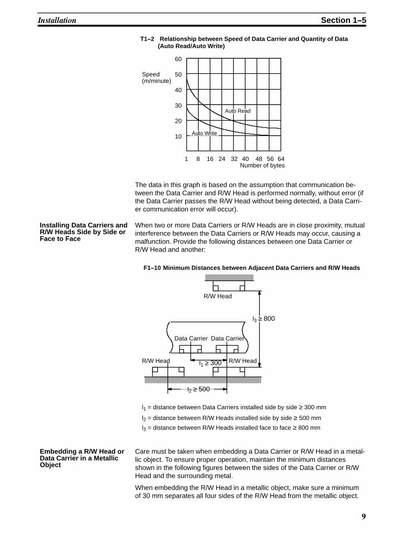
(
Speed(m/minute)
60
50
40
30
20
10
1Number of bytes
8 16 24 32 40 48 56 64
Auto Read
Auto Write
T1--2 Relationship between Speed of Data Carrier and Quantity of Data(Auto Read/Auto Write)
The data in this graph is based on the assumption that communication be-tween the Data Carrier and R/W Head is performed normally, without error (ifthe Data Carrier passes the R/W Head without being detected, a Data Carri-er communication error will occur).
When two or more Data Carriers or R/W Heads are in close proximity, mutualinterference between the Data Carriers or R/W Heads may occur, causing amalfunction. Provide the following distances between one Data Carrier orR/W Head and another:
Data Carrier
l1 ≥ 300
R/W Head
R/W HeadR/W Head
Data Carrier
l1 = distance between Data Carriers installed side by side ≥ 300 mm
l2 = distance between R/W Heads installed side by side ≥ 500 mm
l3 = distance between R/W Heads installed face to face ≥ 800 mm
l3 ≥ 800
l2 ≥ 500
F1--10 Minimum Distances between Adjacent Data Carriers and R/W Heads
Care must be taken when embedding a Data Carrier or R/W Head in a metal-lic object. To ensure proper operation, maintain the minimum distancesshown in the following figures between the sides of the Data Carrier or R/WHead and the surrounding metal.
When embedding the R/W Head in a metallic object, make sure a minimumof 30 mm separates all four sides of the R/W Head from the metallic object.
Installing Data Carriers andR/W Heads Side by Side orFace to Face
Embedding a R/W Head orData Carrier in a MetallicObject
� �������� Section 1--5

�*
Metallicobject
50 mm min.
30 mm min.
30 mm max.
30 mmmin.
30 mm min.
30 mmmin.
R 11 mm min.
Metallic object
F1--11 Embedded R/W Head
Unlike the R/W Head, the Data Carrier does not require separation from themetallic object on all sides in order to operate properly. However, the frontface of the Data Carrier must not be below the surface of the metallic object.
Metallic object
Metallic object
20 mm max.
F1--12 Embedded Data Carrier
1--5--2 System ConnectionID Sensor Units can be mounted to any slot of a C500, C1000H, or C200Hbuilding-block type Programmable Controller. This section explains connec-tions and wiring of all ID Sensor system components.
Refer to Figures F1--1 and F1--2 for connection diagrams.
Connecting the C500-IDS01-V1 ID Sensor1, 2, 3... 1. Before connecting and wiring the ID Sensor Unit, turn OFF the power to
the PC.
� �������� Section 1--5

��
2. Connect the R/W Head to the ID Sensor Unit connector marked “HEAD”. (To disconnect the cable, pull while grasping the outer ring of thecable.)
3. Connect a 24 VDC power supply (250 mA min.) to the 24 VDC terminalsof the ID Sensor Unit. If the power supply is not connected, the Unit willnot be able to communicate with the R/W Head, and an error will occur.Solderless terminals are recommended for the power supply connec-tion. When connecting the power supply to the terminals of the ID Sen-sor Unit, make certain that the correct polarity is observed.
Connecting the C500-IDS02 ID Sensor1, 2, 3... 1. Before connecting and wiring the ID Sensor Unit, turn OFF the power to
the PC.
2. To connect the ID Adapter to the ID Sensor Unit, first assemble a cableof the appropriate length; use the connectors supplied as accessories.(Refer to Preparing the RS-485 Cable on page 11.) Connect one end ofthe cable to the RS-485 connector of the ID Sensor Unit; turn the outerring clockwise until it clicks. Connect the other end to the RS-485 con-nector of the ID Adapter Unit in the same manner. Note that althoughthe connectors on both ends of the RS-485 cable appear identical, theconnector at the ID Adapter end of the cable is insulated from the shield.
3. Connect the cable of the R/W Head to the HEAD connector of theC500-IDA02 ID Adapter Unit. (To disconnect the cable, pull while grasp-ing the outer ring of the cable; do not pull at an angle.)
4. Connect a 24 VDC power supply (250 mA min.) to the 24 VDC terminalsof the ID Sensor Unit. Without this power supply the Unit will not be ableto communicate with the ID Adapter, and an error will occur. Connect a24 VDC power supply (450 mA min.) to the 24 VDC terminals of the IDAdapter. If no power supply is connected, the ID Adapter will not oper-ate, and an error will occur. Solderless terminals are recommended forconnecting the power supply. When connecting the power supply, makecertain that the correct polarity is observed.
Refer to Section 3--3 Monitoring and Figure F1--1 for information on connect-ing the Handheld Programming Console.
Preparing the RS-485 Cable
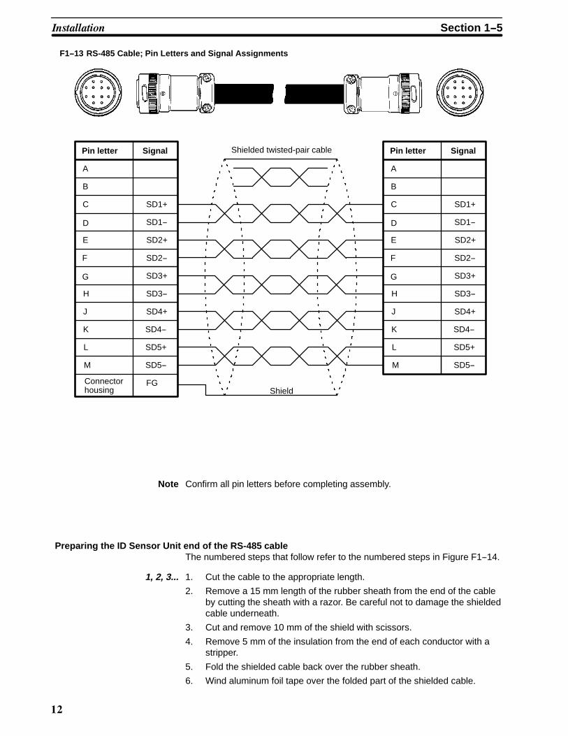
Before assembly The ID Sensor Unit and the ID Adapter communicate through the RS-485interface. To connect the ID Adapter to the ID Sensor Unit, first prepare acable of a length suitable to your needs (maximum length 200 m); use theconnectors supplied as accessories. Note that at the ID Adapter end of theRS-485 cable, the connector must be insulated from the shield.
Use the connectors supplied for the ID Sensor Unit and ID Adapter. Usingtwisted-pair cable, connect the pins to the corresponding letters of each con-nector (pin letters appear on the face of the connector). Be sure to maintainidentical pin letter and signal assignments for both connectors . Figure F1--13shows pin letters and signal assignments.
Connecting the HandheldProgramming Console
Pin letters and signalassignments
� �������� Section 1--5
��
Connectorhousing
Pin letter Signal Shielded twisted-pair cable
Shield
A
SD1+
SD1--
SD2+
SD2--
SD3+
SD3--
SD4+
SD4--
SD5+
SD5--
B
FG
C
D
E
F
G
H
J
K
L
M
Pin letter Signal
A
SD1+
SD1--
SD2+
SD2--
SD3+
SD3--
SD4+
SD4--
SD5+
SD5--
B
C
D
E
F
G
H
J
K
L
M
F1--13 RS-485 Cable; Pin Letters and Signal Assignments
Note Confirm all pin letters before completing assembly.
Preparing the ID Sensor Unit end of the RS-485 cableThe numbered steps that follow refer to the numbered steps in Figure F1--14.
1, 2, 3... 1. Cut the cable to the appropriate length.
2. Remove a 15 mm length of the rubber sheath from the end of the cableby cutting the sheath with a razor. Be careful not to damage the shieldedcable underneath.
3. Cut and remove 10 mm of the shield with scissors.
4. Remove 5 mm of the insulation from the end of each conductor with astripper.
5. Fold the shielded cable back over the rubber sheath.
6. Wind aluminum foil tape over the folded part of the shielded cable.
� �������� Section 1--5

�
(2)
(1)
(3)
(4)
(5)
(6)
15 mm
5 mm
5 mm
Aluminum foil tape
F1--14 Preparing the ID Sensor End of the RS-485 Cable
Preparing the ID Adapter End of the RS-485 Cable (insulated shield)The numbered steps that follow refer to the numbered steps in Figure F1--15.
1, 2, 3... 1. Confirm that the cable is the appropriate length.2. Remove a 15 mm length of the rubber sheath from the end of the cable
by cutting the sheath with a razor. Be careful not to cut deeper than nec-essary.
3. With scissors, cut and remove the entire length of exposed shield.4. Remove 5 mm of the insulation from the end of each conductor with a
stripper.5. Wind vinyl insulating tape over the folded part of the shielded cable.
(2)
(1)
(3)
(4)
(5)
15 mm
Vinyl insulating tape
5 mm
F1--15 Preparing the ID Adapter End of the RS-485 Cable
Disassembling the connectorsRefer to Figure F1--16.
1, 2, 3... 1. Loosen the 2 setscrews with a small standard screwdriver.2. Remove part A from part B by inserting the connector into the Unit, and
turning part B counterclockwise.3. Loosen the 2 clamp screws with a Phillips screwdriver.
� �������� Section 1--5

�#
Part A Part B
Setscrew
Clampscrews
F1--16 Disassembling the Connector
Soldering the twisted-pair wireRefer to Figure F1--17.
1, 2, 3... 1. Slide a 10-mm length of heat-shrink tubing (type F, inside diameter 1.5mm) over each wire, leaving the exposed wire uncovered.
2. Tin each wire and connector terminal.
3. Solder each wire to its mating pin as shown, leaving 1 mm of exposedwire.
4. Slide the heat-shrink tubing over the exposed wire and soldered jointsas shown. Shrink the tubing with a heat gun.
5. Wind insulating vinyl tape over the unused twisted-pair wire.
Soldering iron
F1--17 Soldering the Twisted-Pair Wire to the RS-485 Connector
Twisted-pair wire
1 mm
ConnectorHeat-shrink tubing
Assembling the connectors Refer to Figure F1--18.
1, 2, 3... 1. Assemble the connector by inserting connector part A into the Unit andthreading part B clockwise onto part A.
2. Tighten the 2 setscrews with a small standard screwdriver.
3. Fix the cable by tightening the 2 clamp screws with a Phillips screwdriv-er.
� �������� Section 1--5

�0
F1--18 Assembled Connector
Part A Part B
Setscrew
Clampscrews
The Next Step Once you have completed assembly and installation of the ID Sensor sys-tem, turn to Section 2 for details on setup and operation.
� �������� Section 1--5
��
��� �� �
���������
$"�� ������ ������� � ���� ����������� �� �� ������� ��� � ������� �� �"� � ������ ������� ����� �"�� ������ ��
�2���� � ���� ������������� �� �"� � ������� �������� �� �"� � ������ �������
�������� ����� �� ����������� �� � �!��" ������� ��� �!�� ��� �����!��� � �������3 �������� 2�� ���������3 ���� � ����
����3 ��� ���� �������� ��� 2��" ��������� '( ��������� �����! ��� ����������� �������3 ��� !���� ��������� '(�
�� �� ������� �"�� ���������� 2��� ���������� ��� �"� �������� �� ���� 2��!��� �"� � ������ %��� ��� �"� � % ���
���� ��1�����
6���� �� ������� � ��� ��� ��� � ���� ���������� �����������3 ��� ��� ����������� �� ������ ������������� ���
�����������
���� � �!��" ������� �#� � � � � � � � � � � � � � � � � � � � � � � � � � � � � � � � � � � � � � � � � � � � � � � � � � � � � � � �
������� $!��*���5�����*��� +��� �������� �&� � � � � � � � � � � � � � � � � � � � � � � � � � � � � � � � �
���� $"� %��� ������ �&� � � � � � � � � � � � � � � � � � � � � � � � � � � � � � � � � � � � � � � � � � � � � � � � � � � � � � � �
������� ������ '(�� ��� ��� � � � � � � � � � � � � � � � � � � � � � � � � � � � � � � � � � � � � � � � � � � � � � � � �
������� ������������ �������� ��� � � � � � � � � � � � � � � � � � � � � � � � � � � � � � � � � � � � � � � � �
������� *���� �������� �#� � � � � � � � � � � � � � � � � � � � � � � � � � � � � � � � � � � � � � � � � � � � � � � � � � �
������� 6����������� �� ��� �� �������� �� ��� ������� ��� � � � � � � � � � � � � � � � � � � � � � � �
�'
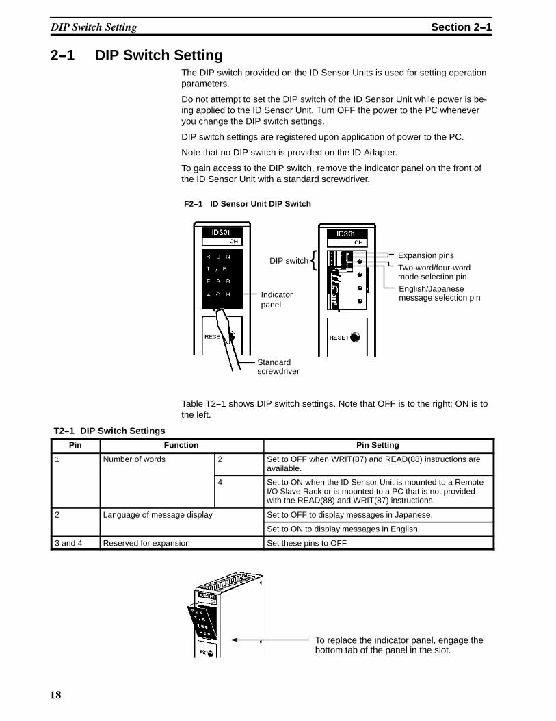
2--1 DIP Switch SettingThe DIP switch provided on the ID Sensor Units is used for setting operationparameters.
Do not attempt to set the DIP switch of the ID Sensor Unit while power is be-ing applied to the ID Sensor Unit. Turn OFF the power to the PC wheneveryou change the DIP switch settings.
DIP switch settings are registered upon application of power to the PC.
Note that no DIP switch is provided on the ID Adapter.
To gain access to the DIP switch, remove the indicator panel on the front ofthe ID Sensor Unit with a standard screwdriver.
Two-word/four-wordmode selection pin
Standardscrewdriver
Indicatorpanel
DIP switch{English/Japanesemessage selection pin
Expansion pins
F2--1 ID Sensor Unit DIP Switch
Table T2--1 shows DIP switch settings. Note that OFF is to the right; ON is tothe left.
T2--1 DIP Switch Settings
Pin Function Pin Setting
1 Number of words 2 Set to OFF when WRIT(87) and READ(88) instructions areavailable.
4 Set to ON when the ID Sensor Unit is mounted to a RemoteI/O Slave Rack or is mounted to a PC that is not providedwith the READ(88) and WRIT(87) instructions.
2 Language of message display Set to OFF to display messages in Japanese.
Set to ON to display messages in English.
3 and 4 Reserved for expansion Set these pins to OFF.
To replace the indicator panel, engage thebottom tab of the panel in the slot.
��� ����� ���� � Section 2--1

�(
2--1--1 Two-Word/Four-Word Mode SelectionThe ID Sensor Unit can be mounted to any slot of a C500, C1000H, orC2000H building-block type Programmable Controller. However, the numberof words the Unit is to be set to, and the programming method (instructions tobe used), differ according to: a) the PC model to which the Unit is mounted;and b) whether the ID Sensor Unit is mounted to a Remote I/O Slave Rack.Table T2--2 shows this relationship.
T2--2 Relationship between Programmable Controller Model, Instructions, and Number of Words
Programmable Controller Unit Mounting Position Instructions Number ofwords
Models with WRIT(87) andREAD(88) instructions
CPU Backplane,Expansion I/O Backplane
WRIT(87) and READ(88) 2
Remote I/O Slave Rack MOV, etc. 4
Models without WRIT(87) andREAD(88) instructions
CPU Backplane,Expansion I/O Backplane,Remote I/O Slave Rack
Note 1. WRIT(87): Intelligent I/O Write InstructionREAD(88): Intelligent I/O Read InstructionWRIT(87) and READ(88) transfer up to 251 words of data between the IDSensor Unit and the CPU of the PC; MOV transfers one word of data at atime.(The Intelligent I/O Read/Write instructions are in fact capable of transfer-ring 255 words, but as four words are used for communication codes, inpractice only 251 words are available for data transfer.)The PC performs I/O refresh each time WRIT(87) and READ(88) are ex-ecuted. However, when MOV is executed, I/O refresh is performed ac-cording to the scanning operation of the CPU.
2. WRIT(87) and READ(88) are available with all C1000H and C2000H PCs,and to C500 PCs provided with either of the following CPUs:
• C500-CPU11-V1• 3G2C3-CPU11-EV13. Use the ID Sensor Unit’s built-in DIP switch to select two- or four-word
mode. When mounting other I/O Units on the PC, make sure the wordsassigned to the ID Sensor Unit have not also been assigned to other I/OUnits.
��� ����� ���� � Section 2--1

�*
Table T2--3 shows bit allocations when the DIP switch of the ID Sensor Unitis set to two-word mode.
T2--3 Bit Allocation When ID Sensor Unit is Set to Two-Word Mode
Word
Bit n n+1
Output Input
00 (PC busy) (ID busy)
01 (PC write end) (ID read in progress)
02 (PC read end) (ID write end)
03 Command processing end flag reset Command error
04 System reset Programming Console MONITOR mode
05 ------ Auto Read/Write Abort end
06 ------ ID unit error
07 ------ ------
08 ------ Data Carrier read/write in progress
09 ------ Command processing end
10 ------ Data Carrier missing error
11 ------ Write protect error
12 ------ Data Carrier communication error
13 ------ Data Carrier address over
14 ------ Data verify error
15 ------ R/W Head disconnect error
Note 1. When the WRIT(87) and READ(88) instructions are used (when the IDSensor Unit is mounted to the CPU Backplane or Expansion I/O Back-plane of a PC having the WRIT(87) and READ(88) instructions), set pin 1of the ID Sensor Unit’s built-in DIP switch to the OFF position for two-wordmode. (Refer to Section 2--1 DIP Switch Setting.)
2. The bits enclosed in parentheses operate automatically when theWRIT(87) and READ(88) instructions are executed. These bits are read-only; do not use for other purposes.
3. To output data to word n with an instruction such as MOV, turn OFF thePC busy, PC write end, and Data Carrier read end flags.
4. The ID read-in-progress flag verifies that data written in common memoryby WRIT(87) is being read by the ID Sensor Unit.
5. The ID read-in-progress flag can be used to verify that data has been cor-rectly written to the common memory of the ID Sensor Unit.
6. The status of word n+1 bits 10 through 15 do not change while beingmonitored by the Programming Console.
7. If an error occurs, the corresponding error flag and the command pro-cessing end flag simultaneously turn ON. The error flag and commandprocessing end flag are turned OFF when the ID Sensor Unit receives anew command or when the command processing end flag reset (word nbit 03) turns ON.
8. Delay command transfer for 1 ms after the system reset flag (word n bit04) has been turned OFF.
Table T2--4 shows the function of each flag when the ID Sensor Unit is set totwo-word mode.
Bit Allocation(Two-Word Operation)
Flag Functions(Two-Word Operation)
��� ����� ���� � Section 2--1

��
T2--4 Function of Each Flag when ID Sensor Unit Is Set to Two-Word Mode
Word Bit Flag name Function
n 00 (PC busy) These flags operate automatically when the WRIT(87) and READ(88)instructions are executed.
01 (PC write end) They are read-only and must not be used for other purposes.
02 (PC read end) Turn OFF these bits when data is to be sent via word n by MOV, etc.
03 Command processingend flag reset
When this flag turns ON and then turns OFF, the commandprocessing end flag (bit 09 of word n+1) is turned OFF. Program sothat this bit operates after a command has been processed.
04 System reset When this flag turns ON and then turns OFF, the ID Sensor Unit isstarted from the initial state.
05 to15
------ Unused. Bits 05 to 15 are reserved for functional expansion. Do notuse them as IRs.
n+1 00 (ID busy) These flags operate automatically when the WRIT(87) and READ(88)instructions are executed.
01 (ID read in progress) They are read-only and must not be used for other purposes.
02 (ID write end)
03 Command error This flag turns ON when the ID Sensor Unit cannot process thecommand sent from the PC when: (1) the command is undefined, or,(2) the command does not include a terminator.
04 Programming ConsoleMONITOR mode
This flag turns ON when the Programming Console connected to theID Sensor Unit is in the MONITOR mode.
05 Auto Read/Write Abort end This flag turns ON when the ID Sensor Unit has received the AutoRead/Write Abort command from the PC and has completed thecommand.
06 ID Unit error This flag turns ON if an error has occurred in the ID Sensor Unit(watchdog timer) or when the RESET switch is pressed.
07 ------ Unused. Bit 07 is reserved for functional expansion. Do not use it as awork bit.
08 Data Carrier read/write inprogress
This flag turns ON while the ID Sensor Unit is reading from or writingto the Data Carrier.
09 Command processing end This flag turns ON when the ID Sensor Unit has processed thecommand received from the PC. Note that this flag turns ONregardless of whether the command execution has ended normally orabnormally.
10 Data Carrier missing error This flag turns ON when the Data Carrier is undetected by the IDSensor Unit after the ID Sensor Unit has received Read, Write, orClear-all instructions from the PC. This flag also turns ON when no 24VDC power is supplied to the C500-IDS01-V1.
11 Write protect error This flag turns ON when an attempt is made to write data to awrite-protected area of the ID Sensor Unit’s memory.
12 Data Carriercommunication error
This flag turns ON if an error has occurred during datacommunication between the ID Sensor Unit and Data Carrier.
13 Data Carrier address over This flag turns ON when the ID Sensor Unit attempts to access amemory address of the Data Carrier beyond the Data Carrier’smemory capacity.
14 Data verify error When the ID Sensor Unit reads/writes data to/from the Data Carrier,the Unit reads the read/written data to compare it against the data ithas read or written first. If the data read last does not match the datathe ID Sensor Unit read or wrote first, an error occurs and this flagturns ON.
15 R/W Head disconnect error This flag turns ON when the R/W Head is not connected to the Unit, orwhen no 24 VDC power is supplied to the C500-IDS02 orC500-IDA02.
��� ����� ���� � Section 2--1

��
Figure F2--2 is a diagram of flag operation when the ID Sensor is set to two-word mode.
WRIT(87) is executed when a given condition is satisfied, and when the IDbusy flag and ID read-in-progress flag are both 0. The instruction is pro-cessed as NOP (no operation) when either flag turns ON.
After the instruction has been executed, the PC write end flag is temporarilyturns ON and the equal flag of the PC turns ON. The equal flag of the PCindicates the instruction has been completed.
Successful data transfer between the Data Carrier and the ID Sensor Unit isindicated when the command processing end flag (word n+1 bit 09) turnsON.
The command processing end flag is not cleared automatically. It is clearedby the command processing end flag reset flag (word n bit 03). Therefore,the operation of the command processing end flag reset flag must be pro-grammed to clear the command processing end flag.
WRIT(87) must not be executed while the command processing end flagturns ON.
READ(88) is automatically executed when a given condition is satisfied, theID busy flag is 0, and when the ID write end flag turns ON. When the Readcommand or Auto Read command has been executed, the ID busy flag isautomatically turned OFF and the ID write end flag is automatically turnedON.
After READ(88) has been executed, the PC read end flag temporarily turnsON and the equal flag of the PC turns ON. Therefore, the equal flag indicatesa completed instruction.
F2--2 Flag Operation when ID Sensor Unit Is Set to Two-Word Mode
PC
WRIT(87) instruction
word n
READ(88) instruction
word n+1
OUT instruction
LD instruction, etc.
Commonmemory
Output bitsBit 03 of word n
Input bits, error flags
Bits 03 to 15 of word n+1
ID Sensor Unit
Dedicatedcommands
Writedata
Readdata
ID SensorUnit Firmware
Analyzes thededicatedcommandsand transfersdata betweenthe commonmemory andData Carriermemory
Commandprocessingend flag reset
Errorinformation,etc.
R/WHead
DataCarrier
IDAdapter
User Program
Flag Operation(Two-Word Operation)
��� ����� ���� � Section 2--1

�
Figure F2--3 shows the relationship between the data processing operationsof the PC, the ID Sensor Unit, and the user program.
Processing by PC
PC busyWord n bit 00
Processing by ID Sensor Unit
Processing by user program
Write data(from PC tocommon memory)
Read data(from commonmemory to PC)
PC write endWord n bit 01
PC read endWord n bit 02
Equal flag
ID busyBit 00 of word (n+1)
ID read inprogressWord n+1 bit 01
Write data(from commonmemory to ID)
Read data(from ID tocommon memory)
ID write endWord n+1 bit 02
Data Carrier read/writein progressWord n+1 bit 08
Command processingend flag resetWord n bit 03
Command processingend Word n+1 bit 09
Execution ofWRIT(87) instruc-tion
WRIT(87)instruction
PC to commonmemory
Data read operation
Data write operation
Commandprocessing
DedicatedcommandsWrite data
Common memoryto ID
Read data
ID tocommon memory
Data is written.
Execution ofREAD(88)instruction
READ(88)instruction
Commonmemory to PC
Data is read.
F2--3 Data Processing when ID Sensor Unit Is Set to Two-Word Mode.
Data Processing(Two-Word Operation)
��� ����� ���� � Section 2--1

�#
Table T2--5 shows bit allocation when the DIP switch of the ID Sensor Unit isset to four-word mode. Refer to Section T2--5 DIP Switch Setting.
T2--5 Bit Allocation when ID Sensor Unit Is Set to Four-Word Mode
Word
Bit n n+1 n+2 n+3
Output Output Input Input
00 Write data 00 PC busy Read data 00 ID busy
01 01 PC write end 01 ID read in progress
02 02 PC read end 02 ID write end
03 03 Commandprocessingend flag reset
03 Command error
04 04 System reset 04 Programming Console MONITOR mode
05 ------ 05 Auto Read/Write Abort end
06 06 ID Unit error
07 07 ------
08 08 Data Carrier read/write in progress
09 09 Command processing end
10 10 Data Carrier missing error
11 11 Write protect error
12 12 Data Carrier communication error
13 13 Data Carrier address over
14 14 Data verify error
15 15 R/W Head disconnect error
Note 1. When the WRIT(87) and READ(88) instructions cannot be used (when theID Sensor Unit is mounted on a PC that is not provided with WRIT(87)and READ(88), or on a Remote I/O Slave Rack), set pin 1 of the DIPswitch on the ID Sensor Unit to ON. Leave pin 2 in the OFF position. Inthis mode, the ID Sensor Unit is set to four-word mode. The status ofword n+3 bits 10 through 15 does not change while those bits are beingmonitored by the Programming Console. (Refer to Section 2--1 DIPSwitch Setting; Section 3--3 Monitoring.)
2. If an error occurs, the corresponding error flag turns ON simultaneouslywith the command processing end flag. The error and command process-ing end flags are turned OFF when the ID Sensor Unit has received anew command or the command processing end flag reset (word n bit 03)has been turned ON.
3. Delay command transfer for one minute after the system reset flag (wordn bit 04) has turned OFF.
Bit Allocation (Four-WordOperation)
��� ����� ���� � Section 2--1

�0
Tables T2--6 and T2--7 show the function of each flag when the ID SensorUnit is set to four-word mode.
T2--6 Function of Each Flag when ID Sensor Unit Is Set to Four-Word Mode (words n, n+1, n+2)
Bit No. Flag Function
Word Bit
n 00 to15
Write data This is the data written from the PC to the common memory of the IDSensor Unit by the MOV command of the PC.
n+1 00 PC busy Program this flag to turn ON when the PC starts reading/writing datato/from the common memory, and to turn OFF when the PC hascompletely read/written the data. While this flag turns ON, the ID SensorUnit cannot access the common memory.
01 PC write end Program this flag to turn ON (see note) after the PC has written data to thecommon memory (by executing MOV, etc; see note). When this flag turnsON, the ID read-in-progress flag (word n+3 bit 01) is automatically turnedON.
02 PC read end Program this flag to turn ON (see note) after the PC has read data fromthe common memory (by executing MOV, etc; see note). When this flagturns ON, the ID write-in-progress flag (word n+3 bit 02) is automaticallyturned ON.
03 Command processingend flag reset
When this flag turns ON and then turns OFF, the command processingend flag (bit 09 of word n+1) is also cleared. Program so that this flag turnsON and then turns OFF after a command has been executed.
04 System reset When this flag turns ON and then turns OFF, the ID Sensor Unit isrestarted from the initial state.
05 to15
------ Unused. Bits 05 to 15 are reserved for functional expansion. Do not usethem as work bits.
00 to15
Read data The PC reads this data from the common memory by executing MOV.
Note When the ID Sensor Unit is mounted to a Remote I/O Slave Rack, the PCdoes not complete writing/reading data until the I/O response time of the Unithas elapsed (refer to Section 3--4 Timing Considerations). Therefore, the PCwrite end and PC read end flags must be programmed to remain at 1 duringthis period.These flags may remain at 1 until immediately before the PC begins writing/reading the next piece of data.
Flag Functions(Four-Word Operation)
��� ����� ���� � Section 2--1

�1
T2--7 Function of Each Flag when ID Sensor Unit Is Set to Four-Word Mode (word n+3)
Bit No. Flag Function
Word Bit
n+3 00 ID busy When the ID Sensor Unit starts writing/reading data to/from thecommon memory, this flag turns ON; when the Unit has finishedwriting/reading the data, it is turned OFF. While this flag is 1, the PCcannot access the common memory.
01 ID read in progress This flag turns ON when the PC write end flag (word n+1 bit 01) turnsON, enabling the ID Sensor Unit to read data fromthe common memory. When the ID Sensor Unit has finished readingthe data, the flag is turned OFF.
02 ID write end This flag turns ON when the ID Sensor Unit has finished writing datato the common memory; it is turned OFF when the PC read end flag(bit 02 of word n+1) turns ON.
03 Commanderror
This flag turns ON if the ID Sensor Unit cannot process the commandsent from the PC when: (1) the command is undefined or; (2) thecommand does not include a terminator.
04 Programming ConsoleMONITOR mode
This flag turns ON when the Programming Console connected to theID Sensor Unit is in the MONITOR mode.
05 Auto Read/WriteAbort end
This flag turns ON when the ID Sensor Unit has received the AutoRead/Write Abort command from the PC and has finished processingthe command.
06 ID Unit error This flag turns ON if an error has occurred in the ID Sensor Unit(watchdog timer) or when the RESET switch has been pressed.
07 ------ Reserved for functional expansion. Do not use it as a work bit.
08 Data Carrierread/write in progress
This flag turns ON while the ID Sensor Unit is reading/writing datafrom/to the Data Carrier.
09 Commandprocessing end
This flag turns ON when the ID Sensor Unit has processed thecommand received from the PC. Note that this flag turns ONregardless of whether the command execution has ended normally orabnormally.
10 Data Carriermissing error
This flag turns ON when the Data Carrier is not detected by the IDSensor Unit after the ID Sensor Unit has received the Read, Write, orClear-all command from the PC. It also turns ON when 24 VDC poweris not being applied to the Unit.
11 Write protect error This flag turns ON when an attempt is made to write data to awrite-protected area of the ID Sensor Unit’s memory.
12 Data Carriercommunication error
This flag turns ON if an error has occurred during data communicationbetween the ID Sensor Unit and Data Carrier.
13 Data Carrieraddress over
This flag turns ON when the ID Sensor Unit attempts to access amemory address of the Data Carrier beyond the Data Carrier’smemory capacity.
14 Data verify error When the ID Sensor Unit reads/writes data from/to the Data Carrier,the unit reads the read/written data to compare it against the datawhich the Data Carrier has read or written first. If the data read lastdoes not match the data the ID Sensor Unit read or wrote first, anerror occurs and this flag turns ON.
15 R/W Head disconnect error This flag turns ON when the R/W Head is not connected to the IDSensor Unit, or when no 24 VDC power is supplied to the C500-IDS02or C500-IDA02.
��� ����� ���� � Section 2--1
��
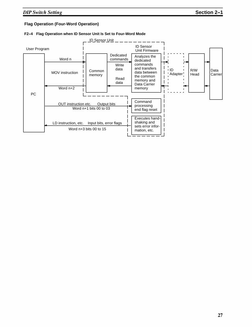
Flag Operation (Four-Word Operation)
F2--4 Flag Operation when ID Sensor Unit Is Set to Four-Word Mode
PC
Word n
MOV instruction
Word n+2
OUT instruction etc.
LD instruction, etc.
Commonmemory
Output bitsWord n+1 bits 00 to 03
Input bits, error flags
Word n+3 bits 00 to 15
ID Sensor Unit
Dedicatedcommands
Writedata
Readdata
ID SensorUnit Firmware
Analyzes thededicatedcommandsand transfersdata betweenthe commonmemory andData Carriermemory
Commandprocessingend flag reset
Executes hand-shaking andsets error infor-mation, etc.
R/WHead
DataCarrier
IDAdapter
User Program
��� ����� ���� � Section 2--1

�'
Figure F2--5 shows the relationship between the data processing operationsof the ID Sensor Unit and the user program when the ID Sensor has been setto four-word mode.
Processing byuser program
Processing byID Sensor Unit
PC busyWord n+1 bit 00
Write dataWord n
PC write endWord n+1 bit 01
PC read endWord n+2 bit 02
Command process-ing end flag resetWord n+1 bit 03
Read dataword n+1
ID busyWord n+3 bit 00
ID read in progressWord n+3 bit 01
Write dataword n
Read dataword n+2
ID write endWord n+3 bit 02
Data Carrier read/writein progressWord n+3 bit 08
Commandprocessing endWord n+3 bit 09
Data read operation
Data write operation
Command is written.
PC to ID
Data is written.Commandprocessing
Data is read.
ID to PC
(Read command or Auto Read command)
F2--5 Data Processing when ID Sensor Unit Is Set to Four-Word Mode.
Data is read.
Timing of Data Transfer When the ID Sensor Unit is mounted to the CPU Backplane or Expansion I/OBackplane of a PC, the contents of the following flags and data are trans-ferred in 1 scan by a differentiation instruction (transfer of the contents of aflag or data only during the scan immediately following a change in thosecontents):
• PC busy flag (word n+1 bit 00)• Write data (word n bits 00 to 15)• PC write end flag (word n+1 bit 01)• PC read end flag (word n+1 bit 02)• Read data (word n+2 bits 00 to 15)
However, if the ID Sensor Unit is mounted to a Remote I/O Slave Rack,transfer is delayed by the I/O response time of the Remote I/O Slave Rack.
Data Processing(Four-Word Operation)
��� ����� ���� � Section 2--1

�(
Therefore, prolong the output of these flags and the data in the program forthe duration of the response period. (Refer to Section 3--4 Timing Consider-ations.)
2--2 The User ProgramThe ID Sensor Unit will not operate unless it is programmed to do so by thePC. The Unit communicates with the Data Carrier through the Read/WriteHead by means of the commands provided by the user program of the PC.
The user program of the PC consists of two modules: one issues commandsto the ID Sensor Unit, and the other sends/receives data. Develop the pro-gram by using instructions such as Intelligent I/O Write (WRIT(87)), IntelligentI/O Read (READ(88)), and MOV.
Figure F2--6 shows the basic operation outline of the two modules of the pro-gram.
OUT instructionetc.
F2--6 User Program Operation Outline
LD instruction,etc.
Commonmemory
ID Sensor Unit
Writedata
Readdata
ID SensorUnit Firmware
Analyzes thededicatedcommandsand transfersdata betweenthe commonmemory andData Carriermemory
Executes hand-shaking andsets error infor-mation,etc.
R/WHead
DataCarrier
IDAdapter
User Program
Intelligent I/OWrite(WRIT(87))
Intelligent I/ORead(READ(87))
Issues dedicatedcommands,sends/receiveswrite/read data
I/O Word
Sends/receivesinformation oncontacts and errors
Note If your PC is not provided with Intelligent I/O Write/Read instructions, transferdata between the PC and ID Sensor Unit by using MOV on a word-by-wordbasis.
As the ID Sensor Unit is controlled by the program contained in the CPU ofthe PC, when the CPU is reset, the ID Sensor Unit is also reset.
The ID Sensor Unit executes commands even when the CPU is in the PRO-GRAM mode.
Communication with the CPU The ID Sensor Unit reads data from and writes data to the Data Carrier inaccordance with the commands sent from the CPU.
The CPU, via the Write, Auto Write, and Clear-all commands, directs the IDSensor Unit to write data to the Data Carrier. Figure F2--7 shows the stepsinvolved in writing data to the Data Carrier.
Relationship between CPUOperation Status and IDSensor Unit
Writing Data to the DataCarrier from the CPU
��� ��� ����� Section 2--2

*
CPU ID SensorUnit
1
3b
4
23a
R/WHead
DataCarrier
F2--7 Writing Data to the Data Carrier from the CPU
IDAdapter
1, 2, 3... 1. The CPU of the PC issues the Write, Auto Write, or Clear-all commandby using WRIT(87) or MOV.
2. The ID Sensor Unit analyzes the command received from the PC.3. If the command is correct, the ID Sensor Unit writes the required data to
the Data Carrier.If the command is illegal, the ID Sensor Unit turns ON the commandprocessing end and command error flags of the PC (refer to p 20 and p24 Bit Allocation).
4. When the ID Sensor Unit has completed writing data to the Data Carrier,the Unit turns ON the command processing end flag of the PC.
If communication with the Data Carrier cannot be established, or if an erroroccurs during communication, the ID Sensor Unit stops data communicationwith the Data Carrier and turns ON the command processing and Data Carri-er communication error flags of the PC.
Steps 1 to 4 compose one write operation.
The CPU, via the Read and Auto Read commands, directs the ID SensorUnit to read data from the Data Carrier. Figure F2--8 shows the steps in-volved in reading data from the Data Carrier.
CPU ID SensorUnit
1
3b
4
23a
R/WHead
DataCarrier
F2--8 Reading Data from the Data Carrier to the CPU
IDAdapter
5
1, 2, 3... 1. The CPU of the PC issues the Read or Auto Read command to the IDSensor Unit by using WRIT(87) or MOV.
2. The ID Sensor Unit analyzes the command it has received from the PC.3. If the command is correct, the ID Sensor Unit reads the required data
from the Data Carrier.If the command is illegal, the ID Sensor Unit turns ON the commandprocessing end and command error flags of the PC (refer to p 20 and p24 Bit Allocation).
4. When the ID Sensor Unit has completed reading data from the DataCarrier, the Unit turns ON the command processing end flag of the PC.
Reading Data from the DataCarrier to the CPU
��� ��� ����� Section 2--2

�
If communication with the Data Carrier cannot be established, or if an erroroccurs during communication, the ID Sensor Unit stops data communicationwith the Data Carrier and turns ON the command processing end and DataCarrier communication error flags of the PC.
5. Next, the PC executes READ(88) or MOV to retrieve the data from theID Sensor Unit.
Steps 1 to 5 compose one read operation.
2--2--1 Program ExamplesThe following figures provide examples of programs; refer to these figuresbefore developing your program. Further examples are presented in Section3 Programming.
Writing Data
a
b
c
c
d
WRIT(87)
MOV
Using Intelligent I/O instructions
Using MOV(when Intelligent I/O instructions are not available)
a
b
c
d
: number of words to be transferred: first destination word number: first word number of ID Sensor Unit: source word number of transfer data
F2--9 Program Examples: Writing Data
PC (user program)
PC (source memory)
d
d
d
d
d
a
b or Data 1
Data 2
Data 3
Data 4
Data 5
a
b
: number of words of each command(see Figures F2--11 to F2--14)
: the first word number where data from eachcommand is stored(see Figures F2--11 to F2--14)
When the Intelligent I/O Write (WRIT(87)) instruction is used, up to 251words of data can be transferred to the ID Sensor Unit at one time. However,
��� ��� ����� Section 2--2

�
if this instruction is not available and MOV is used instead, data from onlyone word can be transferred at a time.
Reading Data
a
b
c
e
d
READ(88)
MOV
Using Intelligent I/O instructions
Using MOV(when Intelligent I/O instructions are not available)
a
b
c
d
: number of words to be transferred: first word number of ID Sensor Unit + 1: first destination word number: first word number of ID Sensor Unit + 2
e : destination word number
F2--10 Program Examples: Reading Data
PC (user program)
PC (destination memory)
e
e
e
e
e
a
c or Data 1
Data 2
Data 3
Data 4
Data 5
When the Intelligent I/O Read (READ(88)) instruction is used, up to 251words of data can be transferred to the PC at one time. However, if this in-struction is not provided and MOV is used instead, data from only one wordcan be transferred at a time.
2--2--2 Communication CommandsThe ID Sensor Unit is provided with six dedicated commands for communi-cating with the Data Carrier through the Read/Write Head. Table T2--8 out-lines these commands.
��� ��� ����� Section 2--2
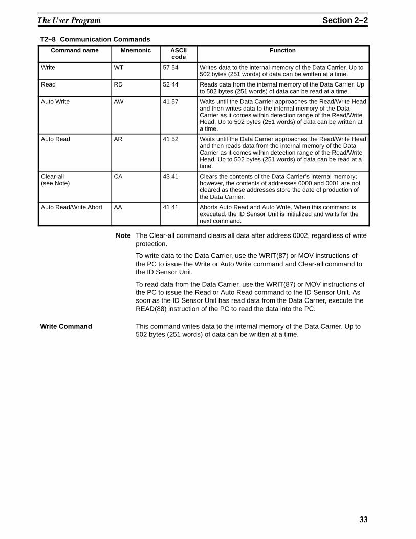
T2--8 Communication Commands
Command name Mnemonic ASCIIcode
Function
Write WT 57 54 Writes data to the internal memory of the Data Carrier. Up to502 bytes (251 words) of data can be written at a time.
Read RD 52 44 Reads data from the internal memory of the Data Carrier. Upto 502 bytes (251 words) of data can be read at a time.
Auto Write AW 41 57 Waits until the Data Carrier approaches the Read/Write Headand then writes data to the internal memory of the DataCarrier as it comes within detection range of the Read/WriteHead. Up to 502 bytes (251 words) of data can be written ata time.
Auto Read AR 41 52 Waits until the Data Carrier approaches the Read/Write Headand then reads data from the internal memory of the DataCarrier as it comes within detection range of the Read/WriteHead. Up to 502 bytes (251 words) of data can be read at atime.
Clear-all(see Note)
CA 43 41 Clears the contents of the Data Carrier’s internal memory;however, the contents of addresses 0000 and 0001 are notcleared as these addresses store the date of production ofthe Data Carrier.
Auto Read/Write Abort AA 41 41 Aborts Auto Read and Auto Write. When this command isexecuted, the ID Sensor Unit is initialized and waits for thenext command.
Note The Clear-all command clears all data after address 0002, regardless of writeprotection.
To write data to the Data Carrier, use the WRIT(87) or MOV instructions ofthe PC to issue the Write or Auto Write command and Clear-all command tothe ID Sensor Unit.
To read data from the Data Carrier, use the WRIT(87) or MOV instructions ofthe PC to issue the Read or Auto Read command to the ID Sensor Unit. Assoon as the ID Sensor Unit has read data from the Data Carrier, execute theREAD(88) instruction of the PC to read the data into the PC.
Write Command This command writes data to the internal memory of the Data Carrier. Up to502 bytes (251 words) of data can be written at a time.
��� ��� ����� Section 2--2

#
Specifies the type ofdata to be written,which can be ASCIIcharacters or hexadeci-mal numbers. Code A(41) specifies ASCIIcharacters, while H (48)specifies hexadecimalnumbers.
15
W
5 7
A/H
41/48
2
*
A
00
T
5 4
1
3 1
0 D
This is OP code represented inASCII code.
This is OP (operation) code indicatingthat the command is Write.
This code selects a Read/Write Headand is always fixed to 1.
ASCII code
Specifies the first address of the DataCarrier memory to which data is to bewritten. Addresses 0002 through07FF (0002 through 2047 decimal)can be specified in hexadecimal.
Write data
Terminator
ASCII code
• 502 bytes max. = 251 words
• Hexadecimal number (0through F): 1,004
• ASCII character data: 502characters
F2--11 Write Command
Read Command The Read command reads data from the internal memory of the Data Carrier.Up to 502 bytes (251 words) of data can be read at a time.
��� ��� ����� Section 2--2
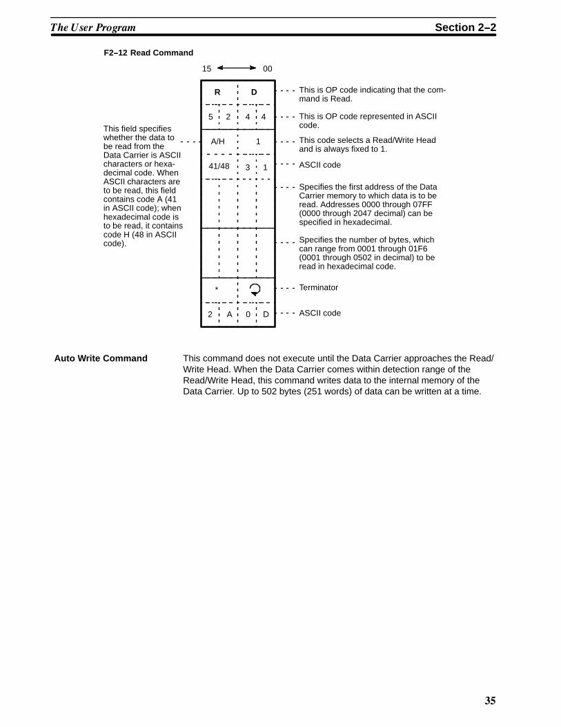
0
15
R
5 2
A/H
41/48
2
*
A
00
D
4 4
1
3 1
0 D
This is OP code indicating that the com-mand is Read.
This is OP code represented in ASCIIcode.
ASCII code
This code selects a Read/Write Headand is always fixed to 1.
Specifies the first address of the DataCarrier memory to which data is to beread. Addresses 0000 through 07FF(0000 through 2047 decimal) can bespecified in hexadecimal.
Terminator
ASCII code
This field specifieswhether the data tobe read from theData Carrier is ASCIIcharacters or hexa-decimal code. WhenASCII characters areto be read, this fieldcontains code A (41in ASCII code); whenhexadecimal code isto be read, it containscode H (48 in ASCIIcode). Specifies the number of bytes, which
can range from 0001 through 01F6(0001 through 0502 in decimal) to beread in hexadecimal code.
F2--12 Read Command
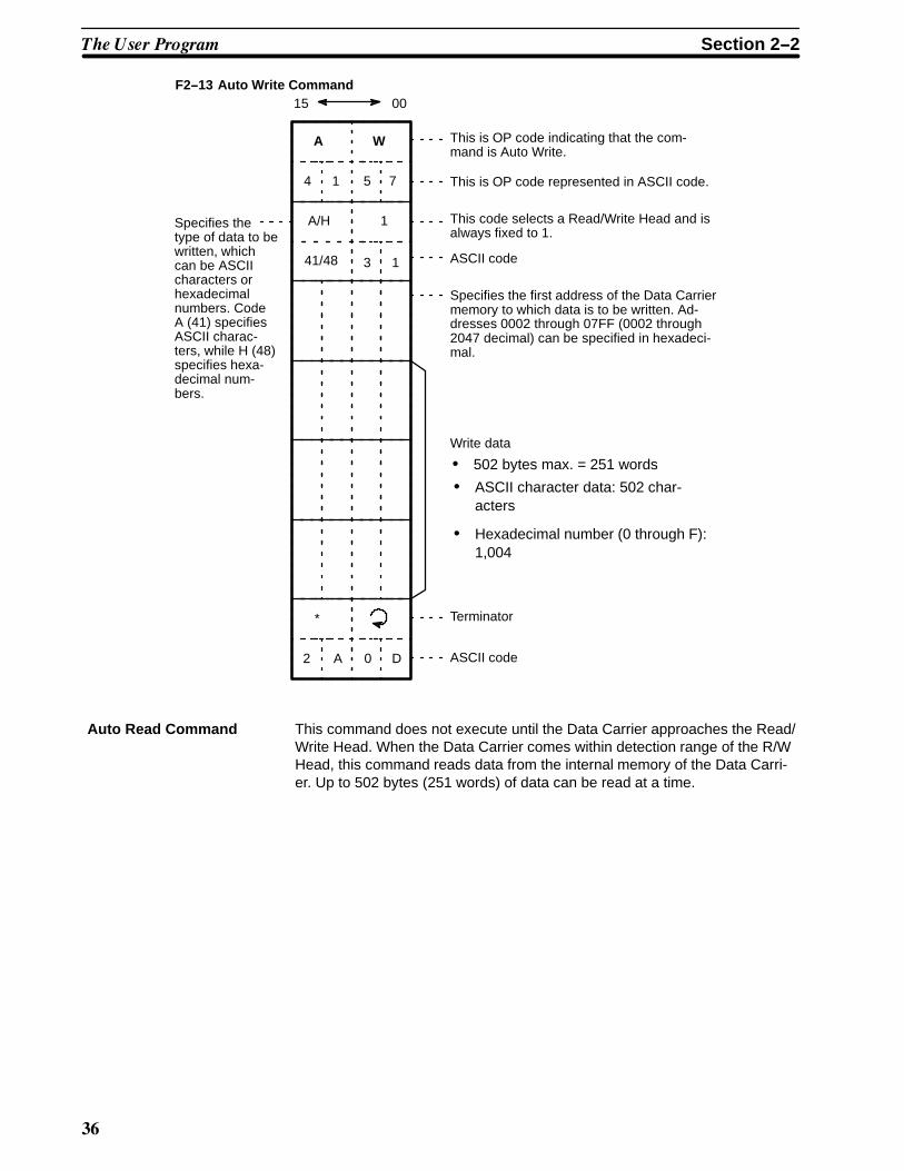
Auto Write Command This command does not execute until the Data Carrier approaches the Read/Write Head. When the Data Carrier comes within detection range of theRead/Write Head, this command writes data to the internal memory of theData Carrier. Up to 502 bytes (251 words) of data can be written at a time.
��� ��� ����� Section 2--2
1
Specifies thetype of data to bewritten, whichcan be ASCIIcharacters orhexadecimalnumbers. CodeA (41) specifiesASCII charac-ters, while H (48)specifies hexa-decimal num-bers.
15
A
4 1
A/H
41/48
2
*
A
00
W
5 7
1
3 1
0 D
This is OP code indicating that the com-mand is Auto Write.
This is OP code represented in ASCII code.
This code selects a Read/Write Head and isalways fixed to 1.
ASCII code
Specifies the first address of the Data Carriermemory to which data is to be written. Ad-dresses 0002 through 07FF (0002 through2047 decimal) can be specified in hexadeci-mal.
Write data
Terminator
ASCII code
• 502 bytes max. = 251 words
• Hexadecimal number (0 through F):1,004
• ASCII character data: 502 char-acters
F2--13 Auto Write Command
Auto Read Command This command does not execute until the Data Carrier approaches the Read/Write Head. When the Data Carrier comes within detection range of the R/WHead, this command reads data from the internal memory of the Data Carri-er. Up to 502 bytes (251 words) of data can be read at a time.
��� ��� ����� Section 2--2

�
15
A
4 1
A/H
41/48
2
*
A
00
R
5 2
1
3 1
0 D
This is OP code indicating that the com-mand is Auto Read.
This is OP code represented in ASCIIcode.
This code selects a Read/Write Headand is always fixed to 1.
ASCII code
Specifies the first address of the DataCarrier memory from which data is to beread. Addresses 0000 through 07FF(0000 through 2047 decimal) can be spe-cified in hexadecimal.
Terminator
ASCII code
This field specifieswhether the data tobe read from theData Carrier isASCII characters orhexadecimal code.When ASCII charac-ters are to be read,this field containscode A (41 in ASCIIcode); when hexa-decimal code is tobe read, it containscode H (48 in ASCIIcode).
Specifies the number of bytes, which canrange from 0001 through 01F6 (0001through 0502 in decimal) to be read inhexadecimal code.
F2--14 Auto Read Command
Clear-all Command This command clears the Data Carrier’s internal memory. However, the con-tents of addresses 0000 and 0001 are not cleared as these addresses storethe date of production of the Data Carrier.
15
C
4 3
2
*
A
00
A
4 1
1
3 10
D
This is OP code indicating that thecommand is Clear-all.
This is OP code represented in ASCII code.
This code selects a Read/Write Headand is always fixed to 1.
ASCII code
Terminator
ASCII code
Blank(no specifica-tion)
0
0
F2--15 Clear-all Command
Auto Read/Write Abort This command aborts Auto Read and Auto Write. When this command is ex-ecuted, the ID Sensor Unit is initialized and waits for the next command.
��� ��� ����� Section 2--2

'
15
A
4 1
2
*
A
00
A
4 1
D
This is OP code indicating that thecommand is Auto Read/Write Abort.
This is OP code represented in ASCII code.
Terminator
ASCII code0
F2--16 Auto Read/Write Abort
This command is regarded as an undefined command when it is received bythe ID Sensor Unit while the Unit is waiting for a command input.
2--2--3 Write Protection
Data written to the Data Carrier can be write-protected. First write the data tothe desired area of the Data Carrier’s memory by using Write, then write-pro-tect the area using the following procedures.
Addresses 0002 to 0005 of the Data Carrier’s memory are used to enable orclear the write protect function. Set these addresses as shown in Table T2--9.
Enabling Write Protection
T2--9 Enabling Write Protection
Address 0002
Address 0003
Bit
7 6 5 4 3 2 1 0
X163
Address 0004
Address 0005
X161
X163
X161
X162
X160
X162
X160
Writeprotect
Write protect begin-ning address
Setting range: 0006through 07FF
Write protect end ad-dressSetting range: 0006through FFFF
(When 0800 is set toFFFF, 07FF is assumed.)
To clear the write protect function, clear all address bits from 0002 through0005.
Bit 7 of address 0002 1 Enables write protect function
0 Clears write protect function
��� ��� ����� Section 2--2

(
Example 1Clearing Write Protection
T2--10 Clearing Write Protection
Address 0002
Address 0003
Bit
7 6 5 4 3 2 1 0
Address 0004
Address 0005
0 0 0 0 0 0 0 0
0 0 0 0 0 0 0 0
0 0 0 0 0 0 0 0
0 0 0 0 0 0 0 0
0 0
0
0
0 0
0
0
Note To disable or clear the write protect function, clear all address bits from 0002through 0007.If the only 0 bit is the 7th bit of address 0002, the function is ignored.
Example 2Write-protecting Addresses 0015 through 0120
T2--11 Write-protecting Addresses 0015 through 0120
Address 0002
Address 0003
Bit
7 6 5 4 3 2 1 0
Address 0004
Address 0005
1 0 0 0 0 0 0 0
0 0 0 1 0 1 0 1
0 0 0 0 0 0 0 1
0 0 1 0 0 0 0 0
8 0
1
0
2 0
1
5
Result0000
0006
0015
0120
07FF
Data Carrier’s memory
Write-protected area
Data can be written to addresses 0006through 0014, and 0121 through 07FF.
��� ��� ����� Section 2--2

#*
Example 3Write-protecting Addresses 0700 through 0350
T2--12 Write-protecting Addresses 0700 through 0350
Address 0002
Address 0003
Bit
7 6 5 4 3 2 1 0
Address 0004
Address 0005
1 0 0 0 0 1 1 1
0 0 0 0 0 0 0 0
0 0 0 0 0 0 1 1
0 1 0 1 0 0 0 0
8 7
0
0
0
3
0
5
Result0000
0006
0350
07FF
Write-protectedarea
0700Write-protectedarea
Addresses 0006 through 0350, and 0700through 07FF are write-protected. Data canbe written to addresses 0351 through 06FF.
Example 4Write-protecting Address 02BE Only
Address 0002
Address 0003
Bit
7 6 5 4 3 2 1 0
Address 0004
Address 0005
1 0 0 0 0 0 1 0
1 0 1 1 1 1 1 0
0 0 0 0 0 0 1 0
1 0 1 1 1 1 1 0
8 2
B
0
E
2
E
B
T2--13 Write-protecting Address 02BE Only
��� ��� ����� Section 2--2

#�
Result0000
0006
02BE
07FF
Write-protectedarea
Only address 02BE iswrite-protected.
Example 5Write-protecting Addresses 0600 through 07FF
Address 0002
Address 0003
Bit
7 6 5 4 3 2 1 0
Address 0004
Address 0005
1 0 0 0 0 1 1 0
0 0 0 0 0 0 0 0
1 1 1 1 1 1 1 1
1 1 1 1 1 1 1 1
8 6
0
F
F
F
0
F
T2--14 Write-protecting Addresses 0600 through 07FF
Result0000
0006
07FF
Write-protectedarea
0600
Addresses 0600 through 07FFare write-protected. When ad-dress 0800 is set to FFFF as anend address, 07FF is assumed.
��� ��� ����� Section 2--2

#�
2--2--4 Registration of Date of Production of Data CarrierThe life of the Data Carrier is approximately 8 years. Develop a program thatmonitors the age of the Data Carrier and notifies the user to replace it beforeit becomes unusable.
Using the CPU’s user program or a Host Computer, execute Read in order toread the date of production and monitor the life of the Data Carrier.
The first 2 bytes (addresses 0000 and 0001) of the Data Carrier’s internalmemory are reserved to store the date of production, which is registered atthe factory before shipment.
No data can be written to these two bytes; an attempt to do so will result in awrite protect error.
Figure F2--17 shows the format in which the date of production is registered;Figure F2--18 gives examples of dates registered.
F2--17 Registration of Data Carrier’s Date of Production
Address 0000
Address 0001
Bit
7 6 5 4 3 2 1 0
Higher digit of month
Higher digit of year
Lower digit of month
Lower digit of year
Note Only the last 2 digits of the year are registered.
F2--18 Examples of Registration of Data Carrier’s Date of Production
Address 0000
Address 0001
Bit
7 6 5 4 3 2 1 0
(1) March, 1988
0 3
8 8
Address 0000
Address 0001
Bit
7 6 5 4 3 2 1 0
1 2
9 0
(2) December, 1990
��� ��� ����� Section 2--2

#
��� ��
!��"������"
$"�� ������ ��1���� �(�� �� ������� �"�� ���������� ���� �������� 2��!��� �"� � ������ %��� ��� �"� � % �� �"� ����( ����������� ������� )*����3 /��� *����3 6���3 /��� 6���3 ���������3 ��� /��� 6���5*���� /2���, �� 2� �����
������ ���� ����������� ������ �(�� ��� ��� �� � ������ %��� ��� �� �!��!��� ����: ������ ���� ����������� �������(�� ��� ��� �� � ������ %��� ��� �� �����!��� �����
�6���� �� ������� ���� ��� ��� ��� ��� 2��� ����������� �� ��1��� ��� � ���� �������
���� ������ '(�� ��� )$!��*��� +���, ��� � � � � � � � � � � � � � � � � � � � � � � � � � � � � � � � � � � � � � � �
������� *������ �� �"� ��� ������� ��� � � � � � � � � � � � � � � � � � � � � � � � � � � � � � � � � � � � � � � � � �
������� 6������ ���� �"� ��� ������� ��� � � � � � � � � � � � � � � � � � � � � � � � � � � � � � � � � � � � � � �
���� ������ '(�� ��� )�����*��� +���, �-� � � � � � � � � � � � � � � � � � � � � � � � � � � � � � � � � � � � � � � �
������� *������ �� �"� ��� ������� ��� � � � � � � � � � � � � � � � � � � � � � � � � � � � � � � � � � � � � � � � � �
������� 6������ ���� �"� ��� ������� ��� � � � � � � � � � � � � � � � � � � � � � � � � � � � � � � � � � � � � � �
���� +��������� ��� � � � � � � � � � � � � � � � � � � � � � � � � � � � � � � � � � � � � � � � � � � � � � � � � � � � � � � � � � � � � �
������� ��������� �"� 7���"��� ���������� ������� ��� � � � � � � � � � � � � � � � � � � � � � � � �
������� +��� ������� ��� � � � � � � � � � � � � � � � � � � � � � � � � � � � � � � � � � � � � � � � � � � � � � � � � � � � �
������� $"� ;.0 ������� ��� � � � � � � � � � � � � � � � � � � � � � � � � � � � � � � � � � � � � � � � � � � � � � � � �
������� /������5��� ������� ��� � � � � � � � � � � � � � � � � � � � � � � � � � � � � � � � � � � � � � � � � � � � � � �
������� 6'/ ��� � � � � � � � � � � � � � � � � � � � � � � � � � � � � � � � � � � � � � � � � � � � � � � � � � � � � � � � � � �
������� ��� *���� )*6�$' �, ��� � � � � � � � � � � � � � � � � � � � � � � � � � � � � � � � � � � � � � � � � � � � � �
������� ���������� *���� )*6�$' �, ��� � � � � � � � � � � � � � � � � � � � � � � � � � � � � � � � � � � � � � � �
������# +������ $��� )$'�$, �#� � � � � � � � � � � � � � � � � � � � � � � � � � � � � � � � � � � � � � � � � � � � � � �
������& '���� <�� �� ��� )'66, �-� � � � � � � � � � � � � � � � � � � � � � � � � � � � � � � � � � � � � � � � � � � �
�������- '���� ����� ��� � � � � � � � � � � � � � � � � � � � � � � � � � � � � � � � � � � � � � � � � � � � � � � � � � � � � �
���� $����� �������������� ��� � � � � � � � � � � � � � � � � � � � � � � � � � � � � � � � � � � � � � � � � � � � � � � � � � � � �
������� ������� �������� $��� ��� � � � � � � � � � � � � � � � � � � � � � � � � � � � � � � � � � � � � � � � � �
������� $��������� $��� ��� � � � � � � � � � � � � � � � � � � � � � � � � � � � � � � � � � � � � � � � � � � � � � � � � �
������� ������ '(�� ��� ��� $����� ������� ��� � � � � � � � � � � � � � � � � � � � � � � � � � � � � � �

##
3--1 Program Examples (Two-Word Mode)Note that the following conditions apply to the example programs in this sec-tion:
1, 2, 3... 1. All example programs are for the C1000H Programmable Controller.
2. The ID Sensor Unit is set to two words, words 000 and 001. Therefore, itis assumed that the WRIT(87) and READ(88) instructions are used. Ifthese instructions are not provided with your PC, transfer data on aword by word basis via MOV.
3. Data sent from the ID Sensor Unit to the PC is stored in the DM area ofthe PC.
Note that the number of words used for each command must be the same asthe number of words used for the WRIT(87) instruction.
3--1--1 Writing to the Data Carrier
This subsection includes program examples of the Write, Auto Write, andClear-all commands.
The Intelligent I/O Write (WRIT(87)) instruction is used to execute the Writecommand, Auto Write command, or Clear-all command. When programming,make sure WRIT(87) is executed only once each time a command is ex-ecuted.
The following program examples are for one transfer operation of 251 wordsof data. When transferring more than 251 words of data (to execute thetransfer operation more than once), refer to Section 3--4 Timing Consider-ations.
00109
Command processing end flag
Execution command
15000 13001
13000
00109
00003
DIFU (13) 15000
13000
WRIT(87)#0007DM 1000000
2550613001
Equal flag
Command processing end flag reset
Command transfer start
Command transfer in progress
Command transfer
Command transfer end
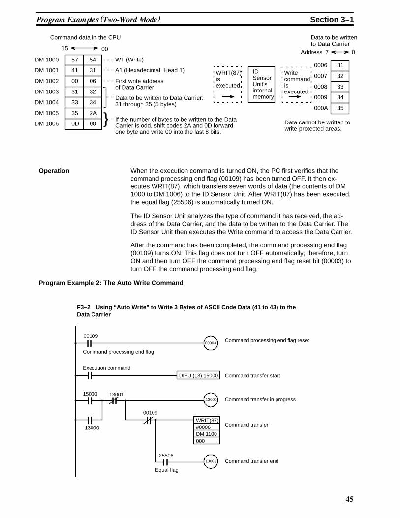
F3--1 Using “Write” to write 5 Bytes of ASCII Code Data (31 to 35) to the DataCarrier
Program Example 1:The Write Command
����� �������� ����� �� !���" Section 3--1
#0
If the number of bytes to be written to the DataCarrier is odd, shift codes 2A and 0D forwardone byte and write 00 into the last 8 bits.
Command data in the CPU
15
DM 1000
DM 1001
DM 1002
DM 1003
DM 1004
DM 1005
DM 1006
57 54
41 31
00 06
31 32
33 34
35 2A
0D 00
00
WT (Write)
A1 (Hexadecimal, Head 1)
First write addressof Data Carrier
Data to be written to Data Carrier:31 through 35 (5 bytes)
Writecommandisexecuted.
31
33
35
32
34
0006
0007
0008
0009
000A
Data to be writtento Data Carrier
Address 7 0
Data cannot be written towrite-protected areas.
}
WRIT(87)isexecuted.
IDSensorUnit’sinternalmemory
Operation When the execution command is turned ON, the PC first verifies that thecommand processing end flag (00109) has been turned OFF. It then ex-ecutes WRIT(87), which transfers seven words of data (the contents of DM1000 to DM 1006) to the ID Sensor Unit. After WRIT(87) has been executed,the equal flag (25506) is automatically turned ON.
The ID Sensor Unit analyzes the type of command it has received, the ad-dress of the Data Carrier, and the data to be written to the Data Carrier. TheID Sensor Unit then executes the Write command to access the Data Carrier.
After the command has been completed, the command processing end flag(00109) turns ON. This flag does not turn OFF automatically; therefore, turnON and then turn OFF the command processing end flag reset bit (00003) toturn OFF the command processing end flag.
Program Example 2: The Auto Write Command
00109
Command processing end flag
Execution command
15000 13001
13000
00109
00003
DIFU (13) 15000
13000
WRIT(87)#0006DM 1100000
2550613001
Equal flag
Command processing end flag reset
Command transfer start
Command transfer in progress
Command transfer
Command transfer end
F3--2 Using “Auto Write” to Write 3 Bytes of ASCII Code Data (41 to 43) to theData Carrier
����� �������� ����� �� !���" Section 3--1

#1
If the number of bytes to be written to the DataCarrier is odd, shift codes 2A and 0D forwardone byte and write 00 into the last 8 bits.
Command data in the CPU
15
DM1100
DM1101
DM1102
DM1103
DM1104
DM1105
41 57
41 31
00 0B
43 2A
0D 00
00
AW (Auto Write)
A1 (Hexadecimal, Head 1)
First write address of Data Carrier
Data to be written to Data Carrier:41 through 43 (3 bytes)
Auto Writecommandisexecuted.
41
43
42
000B
000C
000D
Data to be writtento Data Carrier
Address 7 0
Data cannot be written towrite-protected areas.
}
WRIT(87)isexecuted.
IDSensorUnit’sinternalmemory
41 42
Operation When the execution command is turned ON, the PC checks that the com-mand processing end flag (00109) has been turned OFF. It then executesWRIT(87), which transfers six words of data (the contents of DM 1100 to DM1105) to the ID Sensor Unit. After WRIT(87) has been executed, the equalflag (25506) is automatically turned ON.
The ID Sensor Unit analyzes the type of the command it has received, theaddress of the Data Carrier, and the data to be written to the Data Carrier.The ID Sensor Unit then executes the Auto Write command to access theData Carrier.
After the command has been completed, the command processing end flag(00109) turns ON. This flag does not turn OFF automatically; turn ON andthen turn OFF the command processing end flag reset bit (00003) to turnOFF the command processing end flag.
Program Example 3: The Clear-all Command
00109
Command processing end flag
Execution command
15000 13001
13000
00109
00003
DIFU (13) 15000
13000
WRIT(87)#0003DM 1200000
2550613001
Equal flag
Command processing end flag reset
Command transfer start
Command transfer in progress
Command transfer
Command transfer end
F3--3 Using “Clear-all” to Clear All Memory Areas of the Data Carrier
����� �������� ����� �� !���" Section 3--1

#�
If the number of bytes to becleared is odd, shift codes 2Aand 0D forward one byte andwrite 00 into the last 8 bits.
Command data in the CPU
15
DM1200
DM1201
DM1202
43 41
00 31
2A 0D
00
CA (Clear-all)
1 Clear-allcommandisexecuted.
00
00
00
0002
0003
07FE
Data Carrier memory contentsafter Clear-all execution
Address 7 0
Addresses 0000 and 0001 of the Data Carrier’smemory are reserved for registering the Data Car-rier’s date of production; they cannot be cleared.
WRIT(87)isexecuted.
IDSensorUnit’sinternalmemory
0007FF
Operation When the execution command is turned ON, the PC checks that the com-mand processing end flag (00109) has been turned OFF. It then executesWRIT(87), which transfers three words (the data contained in DM 1200 toDM 1202) to the ID Sensor Unit. After WRIT(87) has been executed, theequal flag (25506) automatically turns ON.
The ID Sensor Unit analyzes the type of the command it has received, andthen issues the Clear-all command to the Data Carrier.
After the command has been completed, the command processing end flag(00109) turns ON. This flag does not turn OFF automatically; turn ON andthen OFF the command processing end flag reset bit (00003) to turn OFF thecommand processing end flag.
3--1--2 Reading from the Data CarrierTo execute the Read and Auto Read commands, the Intelligent I/O Write(WRIT(87)) and Intelligent I/O Read (READ(88)) instructions must be ex-ecuted. WRIT(87) is used to transfer commands; while READ(88) is used toread data to the PC.
Execute WRIT(87) only once each time a command is executed.
The following program examples are for one transfer operation (transferring251 words of data). To transfer more than 251 words of data (to execute thetransfer operation more than once), refer to Section 3--4 Timing Consider-ations.
����� �������� ����� �� !���" Section 3--1

#'
Example 4: The Read Command
00109
Command processing end flag
Execution command
15000
14000
00109
00003
DIFU (13) 15000
14000
WRIT(87)#0005DM 3000000
2550614001
Equal flag
Command processing end flag reset
Command transfer start
Command transfer in progress
Command transfer
Command transfer end
14001 14003
14002
00109
14002
#0002
DM 2000001
2550614003
Equal flag
14001
READ(88)
Data read in progress
Data read
Data read end
F3--4 Using “Read” to Transfer 4 Bytes of Data from Data Carrier to PC fromAddress 0100
Command data of PC
5215
DM 3000DM 3001DM 3002DM 3003DM 3004
4101002A
00443100040D
RDA1Address of first byte to be read from Data CarrierNumber of bytes to be read*
WRIT(87) is executed.
Data is read to PC15 00
DM 2000DM 2001
If the number of bytes to be read is odd, thelast 8 bits of data are undefined.
3133
3234
READ(88)
is executed. ID Sensor Unit’s
internal memory
Read command
is executed.
Data of Data CarrierAddress
0100010101020103
731
3332
34
0
*If the number of bytes to be read is odd, round the number up and divide by 2.
•The Read command specifies that 4 bytes of data are to be read. Therefore, READ(88) reads 2words of data (one word equals 2 bytes).
Operation When the execution command is turned ON, the PC first checks that thecommand processing end flag (00109) has been turned OFF. It then ex-
����� �������� ����� �� !���" Section 3--1

#(
ecutes WRIT(87), which writes the data contained in DM 3000 to DM 3004 tothe internal memory of the ID Sensor Unit.
The ID Sensor Unit analyzes the type of the command it has received, theaddress of the Data Carrier, and the number of bytes to be read. The ID Sen-sor Unit then issues the Read command to the Data Carrier.
After the data read from the Data Carrier has been written to the commonmemory of the ID Sensor Unit, the command processing end flag (00109) isturned ON, enabling the PC to read the data from the common memory. Inthis example, the data is read by READ(88) as soon as the command trans-fer end flag (14001) has been turned ON.
After WRIT(87) and READ(88) have been completed, the equal flag (25506)of the PC automatically turns ON. This flag is does not automatically turnOFF; turn ON and then turn OFF the command processing end flag reset bit(00003) to turn OFF the command processing end flag.
If errors have occurred in the ID Sensor Unit during execution of the Readcommand, the command processing end flag (00109) and the error flags(00103, 00106, 00110 to 00115) are turned ON, but READ(88) is not ex-ecuted.
Example 5: The Auto Read Command
00109
Command processing end flag
Execution command
15000
14000
00109
00003
DIFU (13) 15000
14000
WRIT(87)#0005DM 3100000
2550614001
Equal flag
Command processing end flag reset
Command transfer start
Command transfer in progress
Command transfer
Command transfer end
14001 14003
14002
00109
14002
#0004
DM 2100001
2550614003
Equal flag
14001
READ(88)
Data read in progress
Data read
Data read end
F3--5 Using “Auto Read” to Transfer 7 Bytes of Data from Data Carrier to PC fromAddress 0004
����� �������� ����� �� !���" Section 3--1
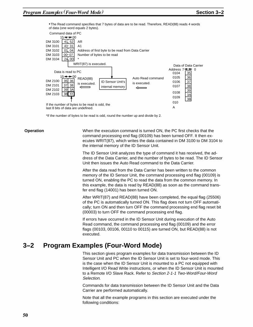
0*
35
3B
Command data of PC
4115
DM 3100DM 3101DM 3102DM 3103DM 3104
4101002A
00523104070D
ARA1Address of first byte to be read from Data CarrierNumber of bytes to be read*
WRIT(87) is executed.
Data is read to PC15 00
DM 2100DM 2101
If the number of bytes to be read is odd, thelast 8 bits of data are undefined.
373638
READ(88)
is executed. ID Sensor Unit’s
internal memory
Data of Data CarrierAddress
0104010501060107
735
3736
38
0
DM 2102DM 2103
39 3Axx
Auto Read command
is executed.
3A39
3B
01080109
010
A
•The Read command specifies that 7 bytes of data are to be read. Therefore, READ(88) reads 4 wordsof data (one word equals 2 bytes).
*If the number of bytes to be read is odd, round the number up and divide by 2.
Operation When the execution command is turned ON, the PC first checks that thecommand processing end flag (00109) has been turned OFF. It then ex-ecutes WRIT(87), which writes the data contained in DM 3100 to DM 3104 tothe internal memory of the ID Sensor Unit.
The ID Sensor Unit analyzes the type of command it has received, the ad-dress of the Data Carrier, and the number of bytes to be read. The ID SensorUnit then issues the Auto Read command to the Data Carrier.
After the data read from the Data Carrier has been written to the commonmemory of the ID Sensor Unit, the command processing end flag (00109) isturned ON, enabling the PC to read the data from the common memory. Inthis example, the data is read by READ(88) as soon as the command trans-fer end flag (14001) has been turned ON.
After WRIT(87) and READ(88) have been completed, the equal flag (25506)of the PC is automatically turned ON. This flag does not turn OFF automati-cally; turn ON and then turn OFF the command processing end flag reset bit(00003) to turn OFF the command processing end flag.
If errors have occurred in the ID Sensor Unit during execution of the AutoRead command, the command processing end flag (00109) and the errorflags (00103, 00106, 00110 to 00115) are turned ON, but READ(88) is notexecuted.
3--2 Program Examples (Four-Word Mode)This section gives program examples for data transmission between the IDSensor Unit and PC when the ID Sensor Unit is set to four-word mode. Thisis the case when the ID Sensor Unit is mounted to a PC not equipped withIntelligent I/O Read Write instructions, or when the ID Sensor Unit is mountedto a Remote I/O Slave Rack. Refer to Section 2-1-1 Two-Word/Four-WordSelection.
Commands for data transmission between the ID Sensor Unit and the DataCarrier are performed automatically.
Note that all the example programs in this section are executed under thefollowing conditions:
����� �������� ����� �� !���" Section 3--2

0�
1, 2, 3... 1. Program examples apply to the C1000H Programmable Controller.2. The ID Sensor Unit is set to four words (words 000, 001, 002, and 003).3. Data sent from the ID Sensor Unit to the PC is stored in the DM area of
the PC.
3--2--1 Writing to the Data CarrierWhen the ID Sensor Unit is mounted to a Remote I/O Slave Rack, com-mands and data must be maintained during the time required for Remote I/Otransfer. Calculate the Remote I/O transfer time using the following formula:
Remote I/O transfer time = 1.4 + (0.2 x (the number of words allocated to theRemote I/O Slave Rack))
For example, if only one Unit is mounted to the Remote I/O Slave Rack, thecalculation would be as follows:
Example: 1.4 + (0.2 x 4) = 2.2 ms
In this case, the data should be maintained for a minimum of 3 ms.
����� �������� ����� �� !���" Section 3--2

0�
00309
Command processing end flag
Execution command
15000
13000
00103
DIFU (13) 15000
13000
00101
25506Equal flag
13001
00100
13000 0030
9
TIM101 0030
0
00301
Command pro-
cessing end
ID busy ID read in
progress
TIM100
13000 TIM100 0030
9
TIMH(15) 100
#0002
TIMH(15) 101
#0002
Command pro-
cessing end
MOV(21)
*DM 0500
000
TIM100@INC(38)
DM 0500
CMP(20)
#1007
KEEP(11)
DM 0500
13001Reset
Command processing end
flag reset
Command transfer start
Command transfer in progress
Command transfer timer
The error of the TIMH instruction is
+0 --0.01 seconds. Set the timer for
0.02 seconds.
Do not use TIMH000 through
TIMH047, as this will cause a com-
mand error.PC busy
PC write end
Command transfer
Command transfer word + 1
Command transfer word end check
Command transfer end
F3--6 Using MOV to Write 5 bytes of ASCII Code Data (31 to 35) to the DataCarrier.
000600070008
07313233
0009000A
3435
DM0500
DM1000
001510
57
00
54DM1001 41 31DM1002DM1003DM1004
003133
063234
DM1005 35 2ADM1006 OD 00
Command data of PC
Command transfer word
WTAIFirst write address of Data Carrier
Write data to Data Carrier (31 to 35)
User program
is executed.ID Sensor Unit’s
internal memory
Write command
is executed
Write data to Data CarrierAddress
If the number of bytes to be written is odd, shiftcodes 2A and 0D forward and fill the last 8 bits with00.
Data cannot be written to
write-protected addresses.
����� �������� ����� �� !���" Section 3--2

0
Operation When the execution command is turned ON, the PC first checks that thecommand processing flag (00309), the ID busy flag (00300), and the ID read-in-progress flag (00301) have been turned OFF. It then executes the com-mand transfer timer.
Use TIM000 through TIM511 or TIMH048 through TIMH 511 for the com-mand transfer timer. Using TIMH000 to TIMH047 will cause a command er-ror.
Make sure that the command processing end flag (00309) is OFF, then write7 words of data (DM1000 to DM1006), via MOV, to the ID Sensor Unit.
Command transfer ends when the command transfer word transfers the endword.
The ID Sensor Unit analyzes the type of command it has received, the ad-dress of the Data Carrier, and the number of bytes to be written. The ID Sen-sor Unit then issues the Write command to the Data Carrier.
When command processing ends, the command processing end flag (00309)is turned ON. This flag (00309) does not turn OFF automatically; turn ON andthen turn OFF the command processing end flag reset bit (00103) to turnOFF the command processing end flag.
3--2--2 Reading from the Data CarrierWhen the ID Sensor Unit is mounted to a Remote I/O Slave Rack, com-mands and data must be maintained during the time required for Remote I/Otransfer. Calculate the Remote I/O transfer time using the formula shown inSection 3-2-1 Writing to the Data Carrier.
����� �������� ����� �� !���" Section 3--2

0#
Execution command
15000
14000
DIFU (13) 15000
14000
00101
25506Equal flag
14001
00100
14000 0030
9
TIM201 0030
0
00301
Command pro-
cessing end
ID busy ID read in
progress
TIM200
14000 TIM200 0030
9
TIMH(15) 200
#0002
TIMH(15) 201
#0002
MOV(21)
*DM 0600
000
TIM200@INC(38)
DM 0600
CMP(20)
#3005
KEEP(11)
DM 0600
1400
1
Reset
Command transfer start
Command transfer in progress
Command transfer timer
The error of the TIMH instruction is
+0 --0.01 seconds. Set the timer for
0.02 seconds.
Do not use TIMH000 through
TIMH047, as this will cause a com-
mand error.PC busy
PC write end
Command transfer
Command transfer word + 1
Command transfer word end check
Command transfer end
F3--7 Using MOV to Read 4 Bytes of Data from Data Carrier Address 0100 to PC
����� �������� ����� �� !���" Section 3--2

00
14001
14002
14002
00102
25506Equal flag
00302
14002 TIM202 00302
Command pro-
cessing end
ID busy ID read in
progress
TIM202
14002 TIM202
TIMH(15) 202
#0002
TIMH(15) 203
#0002
MOV(21)
*DM 0601
002
TIM202@INC(38)
DM 0601
CMP(20)
#2002
KEEP(11)
DM 0601
1400
3
Reset
The error of the TIMH instruction is
+0 --0.01 seconds. Set the timer for
0.02 seconds.
ID write end
0030900103
Command processing end
14003Data read in progress
Read data transfer timer
TIMH instruction error is +0 --0.01 seconds.
Using TIMH000 through TIMH047 will
cause a read data transfer error.PC read end
Data read transfer
Data read transfer word +1
Data read transfer end check
Data read transfer end
Command processing end flag reset
(Continued from previous page)
010001010102
07313233340103
DM0600DM0601
00153020
0000
DM3000 52 44DM3001DM3002DM3003
410100
310004
DM3004 2A 0D
DM2000 31 32
Command data of PC
Command transfer word
RD
*
ID Sensor Unit’s
internal memory
Write data to Data CarrierAddress
0015
33 34DM2001
User program command transfer is executed
Data is read to PC
Data read transfer word
AI
Number of bytes readStart read address of Data Carrier
User program readdata transfer is executed
If the number of bytes to be read is odd, the last 8 bits of
data are undefined.
Read command
is executed.
The read command specifies that 4 bytes of data are
to be read. Therefore, READ(88) reads 2 words of
data (one word equals 2 bytes).
If the number of bytes to be read is odd, round the
number up and divide by 2.
*If the number of bytes to be read is odd, round the number up and divide by 2.
����� �������� ����� �� !���" Section 3--2

01
Operation When the execution command is turned ON, the PC first checks whether thecommand processing end flag (00309), the ID busy flag (00300), and the IDread-in-progress flag (00301) are turned OFF. It then starts the commandtransfer timer.
Use TIM000 through TIM511 or TIMH048 through TIMH511 for the commandtransfer timer. Using TIMH000 through TIMH047 will cause a command error.
Make sure that command processing end flag is OFF, then write 5 words ofdata (DM 3000 to DM 3004) via MOV to the ID Sensor Unit.
The command transfer is complete when the command transfer word trans-fers the end word.
The ID Sensor Unit analyzes the type of command it has received, the ad-dress of the Data Carrier, and the number of bytes to be read. The ID SensorUnit then issues the read command to the Data Carrier.
After the read data has been written to common memory in the ID SensorUnit, the ID write end flag (00302) is turned ON, and the data of the PC canbe read. The read data transfer timer is then executed.
Use TIM000 through TIM511 or TIMH048 through TIMH511 for the read datatransfer timer. Using TIMH000 through TIMH047 will cause a read data trans-fer error.
Using MOV, transfer 2 words of data from the ID Sensor Unit to DM2000 toDM2001. When the read data transfer word transfers the end word, transferof the read data is complete.
When the command processing ends, the command processing end flag(00309) is turned ON. Because this flag (00309) does not turn OFF automati-cally, turn ON and then turn OFF the command processing end flag reset bit(00103) to turn OFF the command processing end flag.
If errors occur in the ID Sensor Unit during execution of the read command,the command processing end flag (00309) and the error flags (00303, 00306,00310 to 00315) are turned ON, but the ID write flag (00302) is not turnedON.
3--3 MonitoringThis section explains the use of the Handheld Programming Console to mon-itor data communication between the ID Sensor and the Data Carrier, and tomonitor errors.
Except where otherwise noted, the operations covered in this section canonly be performed while the Handheld Programming Console is in MONITORmode.
3--3--1 Connecting the Handheld Programming ConsoleUse the C200H-PRO27 Handheld Programming Console to monitor the op-erations of the ID Sensor Unit. Before connecting the Programming Consoleto the ID Sensor Unit, turn OFF the power to the PC.
Use the optional C200H-CN222 (2 m) or C200H-CN422 (4 m) connectingcable to connect the Handheld Programming Console to the ID Sensor Unit.Connect the cable to the connector labeled “MONITOR” on the front panel ofthe ID Sensor Unit.
Refer to Figures F1--1 and F1--2 for connection examples.
Attach the keyboard sheet (provided with the ID Sensor Unit as an accesso-ry) as shown in Figure F3--8.
Attaching the KeyboardSheet
!� �� � Section 3--3

0�
Insert the keyboard sheet into theslots on both sides of the keyboard,and slide into place.
F3--8 Attaching the Keyboard Sheet
3--3--2 Mode Setting
The Handheld Programming Console can be operated in three modes; thefunctions and applications of these modes are outlined in Table T3--1. Usethe Mode selector switch on the Handheld Programming Console to selectthe mode (refer to Figure F3--9).
Note that these modes apply only to the ID Sensor Unit; they do not apply tothe CPU.
Mode selector switch
F3--9 Handheld Programming Console Key Layout
C500-IDS01-V1
!� �� � Section 3--3

0'
T3--1 Programming Console Modes; Functions and Applications
Mode Function Application
RUN In this mode, the CPU transfers data to and from the Data Carrieraccording to the program in the CPU. It is a normal operating modeonly; no key input is possible.
Set the ID Sensor to RUNmode for normal operation.
MONITOR In this mode, use Read, Write,Continuous Write, and Step Writeto monitor data communicationbetween the ID Sensor Unit andthe Data Carrier.
The ID Sensor Unit reads/writesdata directly from/to the DataCarrier.
An easy operation test suchas Read, Step Write orContinuous Write can beperformed when installing theID Sensor.
In this mode, the ID Sensor Unitoperates only via commandsinput from the HandheldProgramming Console;commands from the CPU areignored.
The ID Sensor Unit repeatedlyexecutes Read, Write, Auto Read,or Auto Write. If an error occurs,the corresponding error code isdisplayed on the ProgrammingConsole. (Refer to Section3--3--10 Error Codes.)
Use this mode to test (TEST)and adjust the speed of theData Carrier and the distancefrom the Read/Write Head.
Any communication error that hasoccurred in RUN mode isdisplayed on the ProgrammingConsole.
If an error occurs, useMONITOR mode todetermine the cause (Referto Section3--3--9 Error Log Display.)
PROGRAM Not used. ------
RUN Mode In this mode, the CPU transfers data to and from the Data Carrier accordingto the program in the CPU. It is a normal operating mode; data cannot beinput.
The following message appears on the Handheld Programming Console dis-play.
<RUN>
PROGRAM Mode This mode is not used, as the ID Sensor Unit cannot be programmed. Whenthe mode selector on the Programming Console is set to the PROGRAM po-sition, the following message is displayed.
<PROGRAM>
<MODE ERROR>
MONITOR Mode When the selector is set to the MONITOR position, the following message isdisplayed, indicating that the operation of the ID Sensor Unit can be moni-tored.
<MONITOR> BZ
Note 1. The CPU program is not executed in this mode. MONITOR mode is usedspecifically for monitoring operation of the ID Sensor Unit.
!� �� � Section 3--3
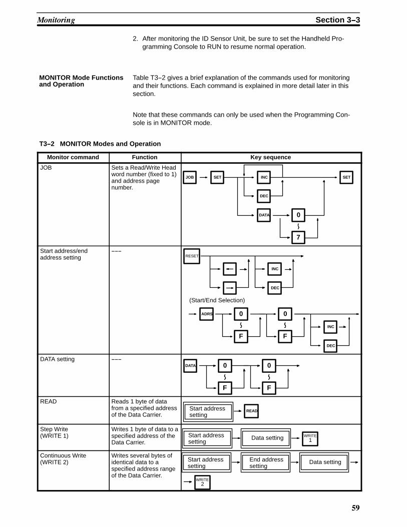
0(
2. After monitoring the ID Sensor Unit, be sure to set the Handheld Pro-gramming Console to RUN to resume normal operation.
Table T3--2 gives a brief explanation of the commands used for monitoringand their functions. Each command is explained in more detail later in thissection.
Note that these commands can only be used when the Programming Con-sole is in MONITOR mode.
T3--2 MONITOR Modes and Operation
Monitor command Function Key sequence
JOB Sets a Read/Write Headword number (fixed to 1)and address pagenumber.
JOB SET INC
DEC
DATA 0
7
SET
Start address/endaddress setting
------RESET
ADRS 0 0
F
INC
DEC
F
INC
DEC
(Start/End Selection)
DATA setting ------0 0DATA
F F
READ Reads 1 byte of datafrom a specified addressof the Data Carrier.
READStart addresssetting
Step Write(WRITE 1)
Writes 1 byte of data to aspecified address of theData Carrier. 1
WRITEStart addresssetting
Data setting
Continuous Write(WRITE 2)
Writes several bytes ofidentical data to aspecified address rangeof the Data Carrier.
WRITE2
Start addresssetting
End addresssetting
Data setting
MONITOR Mode Functionsand Operation
!� �� � Section 3--3

1*
Monitor command Key sequenceFunction
Monitor test (TEST) Use this command torepeatedly executeRead, Write, Auto Read,or Auto Write in aspecified address rangeof the Data Carrier andmonitor error messagesthat occur as a result ofcommand execution.The specified addressrange is accessed atone-second intervals.
TEST 1
4
Start addresssetting
End addresssetting
(Read or Auto Read)
Data Setting
(Write or Auto Write)
Error log display Use this command todisplay errors thatoccurred while the IDSensor was in RUNmode. Error messagesand correspondingcodes are displayed,and errors are classifiedas either “newest error”or “statistical error”.
4
3
2
ERR INC
DEC
3
4
SET
SET SET
1
1
2
(Date change)
: displays newest error information
: displays statistical error information
: clears newest error information
: clears statistical error information
Initial Display When the mode selector is in the MONITOR mode, the following message isdisplayed:
<MONITOR> BZ Indicates that the buzzer is enabled.
Press the “B” key to alternately enable ordisable the buzzer.
Note When the Programming Console is in MONITOR mode and the buzzer is en-abled, only the following keys are functional:
JOBDATARESET ADRS B
RESET Display Press the RESET key to return the screen to RESET status. Press the RE-SET key either after a monitoring operation has been completed, or during amonitoring operation to abort that operation.
The following message is displayed when the RESET key is pressed:
!� �� � Section 3--3
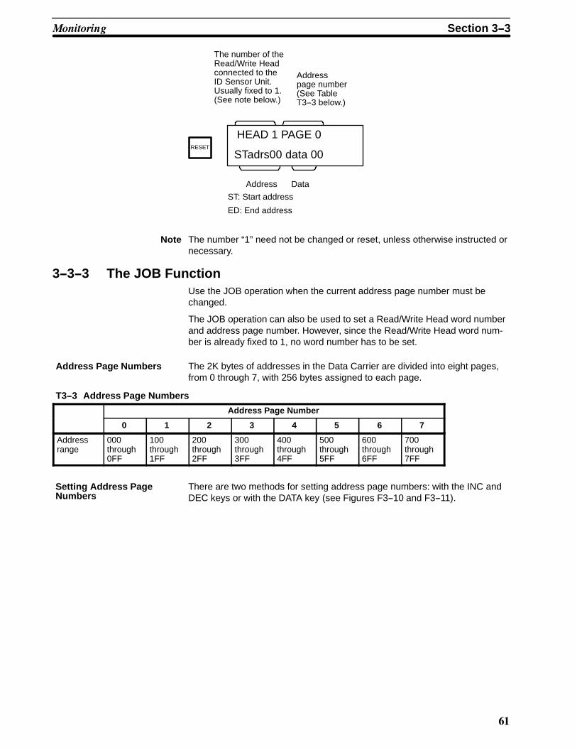
1�
HEAD 1 PAGE 0
STadrs00 data 00
The number of theRead/Write Headconnected to theID Sensor Unit.Usually fixed to 1.(See note below.)
Address
ST: Start address
ED: End address
Addresspage number(See TableT3--3 below.)
Data
RESET
Note The number “1” need not be changed or reset, unless otherwise instructed ornecessary.
3--3--3 The JOB FunctionUse the JOB operation when the current address page number must bechanged.
The JOB operation can also be used to set a Read/Write Head word numberand address page number. However, since the Read/Write Head word num-ber is already fixed to 1, no word number has to be set.
Address Page Numbers The 2K bytes of addresses in the Data Carrier are divided into eight pages,from 0 through 7, with 256 bytes assigned to each page.
T3--3 Address Page Numbers
Address Page Number
0 1 2 3 4 5 6 7
Addressrange
000through0FF
100through1FF
200through2FF
300through3FF
400through4FF
500through5FF
600through6FF
700through7FF
There are two methods for setting address page numbers: with the INC andDEC keys or with the DATA key (see Figures F3--10 and F3--11).
Setting Address PageNumbers
!� �� � Section 3--3

1�
HEAD 1 PAGE 0
STadrs00 data 00
HEAD 1 PAGE 0
STadrs00 data 00
HEAD 1 PAGE 1
STadrs00 data 00
HEAD 1 PAGE 2
STadrs00 data 00
HEAD 1 PAGE 1
STadrs00 data 00
HEAD 1 PAGE 3
STadrs00 data 00
Press the JOB key while the initialmessage or reset message is dis-played.
A R/W Head number can now be set;as the word number is already fixed,press the SET key to continue.
The address page number is in-creased by one each time the INC keyis pressed.
The address page number is de-creased by one each time the DEC keyis pressed.
After the address page number hasbeen selected, press the SET key. Theaddress page number must be withinthe range of 0 through 7. If any othervalue is set, an error will occur and theerror message “ADDRESS E” will bedisplayed upon execution of a subse-quent command.
DEC
INC
JOB
SET
INC
SET
F3--10 Setting Address Page Numbers (INC/DEC keys)
!� �� � Section 3--3
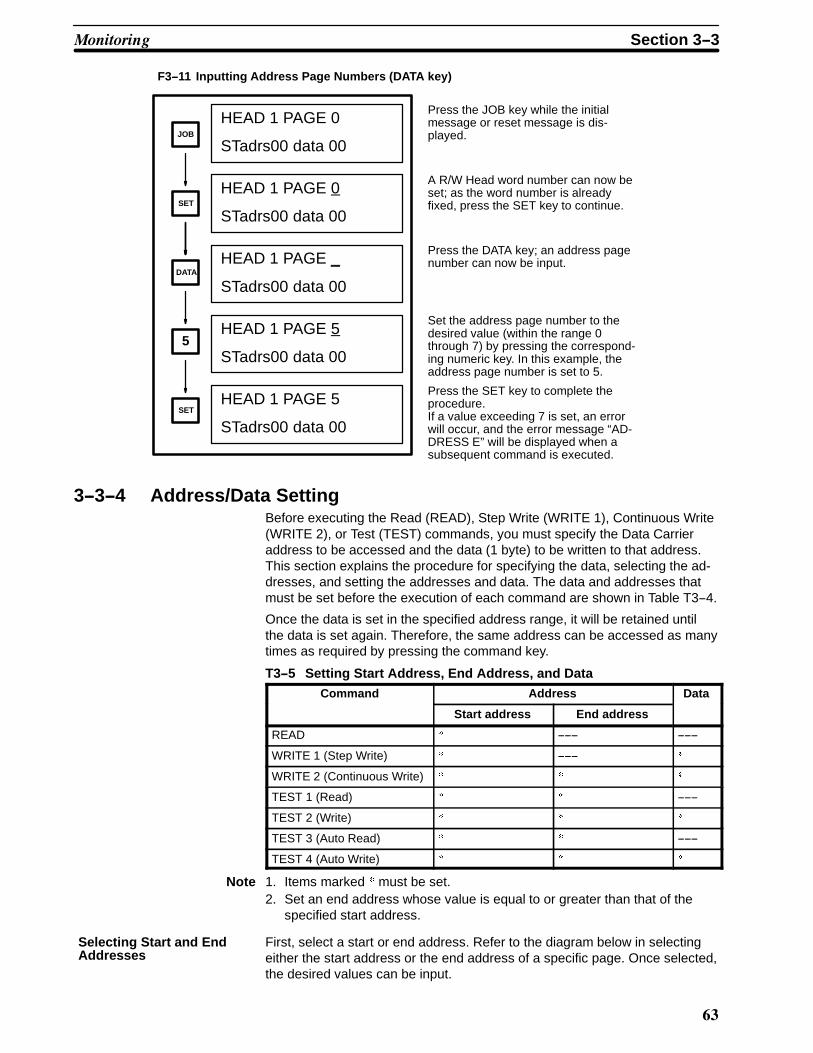
1
HEAD 1 PAGE 0
STadrs00 data 00
HEAD 1 PAGE 0
STadrs00 data 00
HEAD 1 PAGE _
STadrs00 data 00
HEAD 1 PAGE 5
STadrs00 data 00
HEAD 1 PAGE 5
STadrs00 data 00
Press the JOB key while the initialmessage or reset message is dis-played.
A R/W Head word number can now beset; as the word number is alreadyfixed, press the SET key to continue.
Press the DATA key; an address pagenumber can now be input.
Set the address page number to thedesired value (within the range 0through 7) by pressing the correspond-ing numeric key. In this example, theaddress page number is set to 5.
Press the SET key to complete theprocedure.If a value exceeding 7 is set, an errorwill occur, and the error message “AD-DRESS E” will be displayed when asubsequent command is executed.
SET
DATA
JOB
SET
5
F3--11 Inputting Address Page Numbers (DATA key)
3--3--4 Address/Data SettingBefore executing the Read (READ), Step Write (WRITE 1), Continuous Write(WRITE 2), or Test (TEST) commands, you must specify the Data Carrieraddress to be accessed and the data (1 byte) to be written to that address.This section explains the procedure for specifying the data, selecting the ad-dresses, and setting the addresses and data. The data and addresses thatmust be set before the execution of each command are shown in Table T3--4.
Once the data is set in the specified address range, it will be retained untilthe data is set again. Therefore, the same address can be accessed as manytimes as required by pressing the command key.
T3--5 Setting Start Address, End Address, and DataCommand Address Data
Start address End address
READ " ------ ------
WRITE 1 (Step Write) " ------ "
WRITE 2 (Continuous Write) " " "
TEST 1 (Read) " " ------
TEST 2 (Write) " " "
TEST 3 (Auto Read) " " ------
TEST 4 (Auto Write) " " "
Note 1. Items marked = must be set.2. Set an end address whose value is equal to or greater than that of the
specified start address.
First, select a start or end address. Refer to the diagram below in selectingeither the start address or the end address of a specific page. Once selected,the desired values can be input.
Selecting Start and EndAddresses
!� �� � Section 3--3

1#
HEAD 1 PAGE 1
STadrs00 data 00
HEAD 1 PAGE 1
EDadrsFF data 00
Startaddress
or
Endaddress
“FF” is displayed onpower application.
Press the RESET button to display thereset screen, as shown on the left.
Pressing the left or right arrow key al-ternately displays the current start andend addresses.
RESET
Note This operation displays only the current addresses; it cannot be used tochange an address.
Setting Addresses First select either a start address (STadrs) or end address (EDadrs) as de-scribed under the previous heading Selecting Start and End Addresses.Then enter the desired value for the start address or end address. The val-ues can be input either directly (Figure F3--12) or by using the INC/DEC keys(Figure F3--13).
HEAD 1 PAGE 1
STadrs_ data 00
HEAD 1 PAGE 1
STadrs1 data 00
HEAD 1 PAGE 1
STadrs1F data 00
Change the current address (start orend address) by first pressing theADRS key and then entering the de-sired value. In this example, the startaddress is changed to 1F.
Enter the value (from 0 through F) ofthe leftmost digit of the address. Inthis example, the higher digit is 1.
Enter the value (from 0 through F) ofthe rightmost digit of the address. Inthis example, the lower digit is F.
ADRS
F
1
F3--12 Setting Addresses (Direct Input)
The address can also be input or changed using the INC or DEC keys, asshown in Figure F3--13.
HEAD 1 PAGE 1
STadrs20 data 00
HEAD 1 PAGE 1
STadrs1F data 00
The address is decremented each timethe DEC key is pressed.
The address is incremented each timethe INC key is pressed. Note that theaddress is set in hexadecimal.
DEC
INC
F3--13 Setting Addresses (INC/DEC)
!� �� � Section 3--3
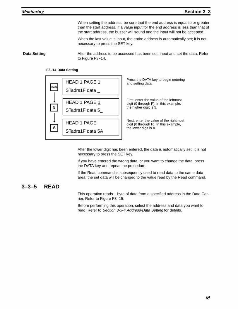
10
When setting the address, be sure that the end address is equal to or greaterthan the start address. If a value input for the end address is less than that ofthe start address, the buzzer will sound and the input will not be accepted.
When the last value is input, the entire address is automatically set; it is notnecessary to press the SET key.
Data Setting After the address to be accessed has been set, input and set the data. Referto Figure F3--14.
HEAD 1 PAGE 1
STadrs1F data _
HEAD 1 PAGE 1
STadrs1F data 5_
HEAD 1 PAGE
STadrs1F data 5A
Press the DATA key to begin enteringand setting data.
First, enter the value of the leftmostdigit (0 through F). In this example,the higher digit is 5.
Next, enter the value of the rightmostdigit (0 through F). In this example,the lower digit is A.A
5
DATA
F3--14 Data Setting
After the lower digit has been entered, the data is automatically set; it is notnecessary to press the SET key.
If you have entered the wrong data, or you want to change the data, pressthe DATA key and repeat the procedure.
If the Read command is subsequently used to read data to the same dataarea, the set data will be changed to the value read by the Read command.
3--3--5 READThis operation reads 1 byte of data from a specified address in the Data Car-rier. Refer to Figure F3--15.
Before performing this operation, select the address and data you want toread. Refer to Section 3-3-4 Address/Data Setting for details.
!� �� � Section 3--3

11
HEAD 1 PAGE 1
STadrs1F data 00
HEAD 1 PAGE 1
RDadrs1F data
HEAD 1 PAGE 1
RDadrs1F data CS
HEAD 1 PAGE 1
RDadrs1F NO DC E
HEAD 1 PAGE 1
RDadrs1F error 72
HEAD 1 PAGE 1
STadrs1F data C8
startaddresssetting
start address (read address)
Indicates that Read will be executed.
Read data
Error message
or
Error code number
Press the READ key; the data inthe specified start address will beread.
Set the start address from whichthe data is to be read.
When the read operation hasbeen completed, the read data isdisplayed.
To perform another operation orto abort the READ operation,press the RESET key. The dis-play will return to the reset dis-play. In this example, the displayindicates the reset status. Anoth-er operation can now be per-formed.
If an error has occurred duringthe READ operation, the buzzerwill sound for 2 seconds, and anerror message will be displayed(refer to Section 3--3--10 ErrorCodes).
Pressing the left or right arrowkey will toggle the display be-tween the error message andthe corresponding error code.
RESET
READ
Normalcompletion
When anerror occurs
F3--15 READ
3--3--6 Step Write (WRITE 1)
This operation writes 1 byte of specified data to a specified address in theData Carrier. Refer to Figure F3--16 .
Before performing this operation, select the address and the data you want towrite. Refer to Section 3-3-4 Address/Data Setting for details.
!� �� � Section 3--3

1�
HEAD 1 PAGE 1
STadrs1F data 83
HEAD 1 PAGE 1
SWadrs1F data
HEAD 1 PAGE 1
SWadrs1F data 83
HEAD 1 PAGE 1
SWadrs1F NO DC E
HEAD 1 PAGE 1
SWadrs1F error 72
HEAD 1 PAGE 1
STadrs1F data 83
start ad-dress/datasetting
start address(write address)
Indicates that Step Write will be ex-ecuted.
Data to be written
Error code number
Normal com-pletion
When anerror occurs
Data tobe written
Press the WRITE 1 key towrite the data to the start ad-dress and begin the StepWrite operation.
Set the data to be written andthe address in the Data Carri-er the data is to be written to.
If the data is written correctly,it is displayed as shown inthe example.
To perform another opera-tion, or to abort the StepWrite operation, press theRESET key. The display willreturn to the reset status. Inthis example, the display in-dicates the reset status.Another operation can nowbe performed.
If an error occurs during theoperation, the buzzer soundsfor 2 seconds, and an errormessage is displayed (Referto Section 3--3--10 ErrorCodes).
Pressing the left or right ar-row key will toggle the dis-play between the error mes-sage and the correspondingerror code.
or
RESET
1WRITE
F3--16 Step Write (WRITE 1)
Error message
3--3--7 Continuous Write (WRITE 2)
This operation continuously writes several bytes of the same data to a speci-fied address range in the Data Carrier. Refer to Figure F3--17.
Before performing this operation, select the address and the data you want towrite. Refer to Section 3-3-4 Address/Data Setting for details.
!� �� � Section 3--3

1'
HEAD 1 PAGE 1
STadrs1F data 54
HEAD 1 PAGE 1
CWadrs1F data 54
HEAD 1 PAGE 1
CWadrs28 data 54
HEAD 1 PAGE 1
CWadrs3F data 54
HEAD 1 PAGE 1
CWadrs32 NO DC E
HEAD 1 PAGE 1
CWadrs1F data 72
Indicates that ContinuousWrite will be executed.
Data to be written
Errormessage
Error code number
Normalcompletion
When anerror occurs
Data tobe written
HEAD 1 PAGE 1
STadrs1F data 54
ST: start addressED: end address
start address ≥ end address
startaddress
End address
Address at which anerror has occurred
Select the start and end ad-dresses, as well as the datato be written.
Press the WRITE 2 key.“CW” is displayed in the low-er left corner of the Program-ming Console display, indi-cating that Continuous Writeis being executed. The datais written to the addresses inthe range specified.
When the data is written cor-rectly to all addresses and theContinuous Write operation iscompleted, the written dataappears as shown in the ex-ample.
Pressing the left or right ar-row key will toggle the dis-play between the error mes-sage and the correspondingerror code.
If an error occurs during theContinuous Write operation,the buzzer sounds for 2 sec-onds, and an error messageis displayed. (Refer to Sec-tion 3--3--10 Error Codes.)
To perform another opera-tion or abort the ContinuousWrite operation, press theRESET key, and the displaywill return to reset status. Inthis example, the display in-dicates the reset status.Another operation can nowbe performed.
or
start ad-dress/datasetting
WRITE
2
RESET
F3--17 Continuous Write (WRITE 2)
3--3--8 Monitor Test (TEST)This operation repeatedly executes (at 1-second intervals) either the Read,Write, Auto Read, or Auto Write command in specified addresses of the DataCarrier. Any command errors that occur are displayed. Use this operation to
!� �� � Section 3--3

1(
test and adjust the distance of the Data Carrier from the Read/Write Head,and the travel speed of the Data Carrier. Refer to Figure F3--18.
Before performing this operation, select the address and the data you want toread or write. Refer to Section 3-3-4 Address/Data Setting for details.
HEAD 1 PAGE 1
STadrs1F data 29
TEST 1 2 3 4
RD WT AR AW
TEST RD
TEST RD
error72 NO DC E
HEAD 1 PAGE 1
STadrs1F data 29
start address/end address/da-ta setting
Errormessage
Error codenumber
When anerror occurs
Data tobe written
ST: start addressED: end address
start address ≤ end address
These commands areselected by pressing thefollowing keys:
: read (RD)
: write (WT)
: auto read (AR)
: auto write (AW)
First, select the address tobe accessed and the datato be written or read. Whenexecuting Write or AutoWrite, remember to set thedata to be written as wellas the address.
Press the TEST key. Ex-ecute a command from thecommand menu (displayedon the screen) by pressingthe number that corre-sponds to the commandyou want to execute.
In this example, the READcommand is selected.
From the start address tothe end address of the DataCarrier, the READ com-mand is executed on a step-by-step basis. In one-se-cond intervals, data is readand checked for errors. If anerror occurs while a com-mand is being executed, thecorresponding error numberand message are displayed.(Refer to Section 3--3--10Error Codes). The errormessage and code disap-pear automatically if thenext command is executedcorrectly.
While the TEST operationis being performed, the T/RLED indicator on the IDSensor Unit blinks.
To begin another commandor to abort the TEST opera-tion, press the RESET keyand the display will returnto the reset status.
4
3
2
TEST
1
RESET
1
F3--18 Monitor Test (TEST)
!� �� � Section 3--3

�*
3--3--9 Error Log Display (ERR)This operation displays errors that have occurred while the ID Sensor Unitwas in the RUN mode and the user program was being executed. The errorsare displayed in two formats: newest error information and statistical errorinformation.
“Newest error” is a list of the 30 most recent errors; “statistical error” displaysthe number of times an error has occurred since a predetermined startingdate. The MCBF (Mean Cycle Between Failures: total number of commands/total number of errors) is also displayed. To change the date from which er-rors are to be monitored (registration date), execute the statistical error clear-ing operation (key 4) as shown in Figure F3--19.
ERROR1 2 3 4
L S CL CS
Error formats can be selectedby pressing the following keys:
: displays newest errorinformation
: displays statistical errorinformation
: clears newest errorinformation
: clears statistical errorinformation
Press the ERR key to display thenewest error information or statisti-cal error information.
Use keys 1 through 4 to display orclear desired error information.
ERR
4
3
2
1
F3--19 Error Log Display (ERR)
The error information storage area of the ID Sensor Unit is undefined upondelivery. Before using the ID Sensor Unit, press key 3 to clear newest errorinformation, and key 4 to clear statistical error information.
Error information is backed up by a capacitor for up to 15 days (at 258C). Ifthe ID Sensor Unit is left OFF for more than 15 days, the error informationbecomes undefined and the error information must be cleared again.
!� �� � Section 3--3

��
Clearing Newest Error Information (Key 3)
ERROR1 2 3 4
L S CL CSERR
3
SET
CLEAR LAT. ERRORS
CLEAR L?PUSH SET
“L” = “Newest”
HEAD 1 PAGE 1
STadrs1F data 29
When the ERR key is pressed, themenu shown at left is displayed.Press key 3 to choose the newest er-ror clearing operation.
When the information has beencleared, the display returns to theRESET status.
The message “CLEAR L?” is dis-played, asking for confirmation thatthe information is to be cleared.Press RESET to preserve the errorinformation. Press SET to clear theinformation.
F3--20 Clearing Newest Error Information
!� �� � Section 3--3
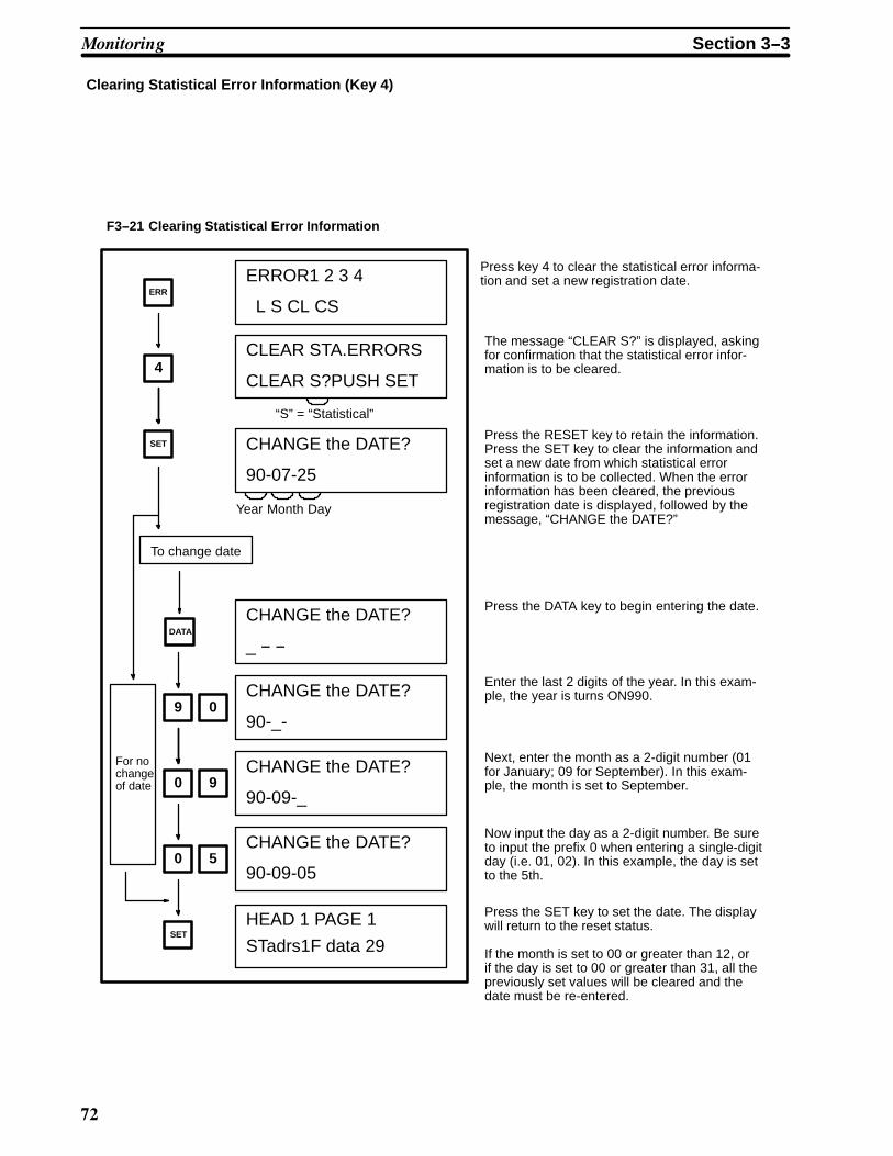
��
Clearing Statistical Error Information (Key 4)
CHANGE the DATE?
90-07-25
HEAD 1 PAGE 1
STadrs1F data 29
ERROR1 2 3 4
L S CL CS
CLEAR STA.ERRORS
CLEAR S?PUSH SET
ERR
4
SET
SET
DATA
0
0
9
5
9
0
To change date
For nochangeof date
“S” = “Statistical”
Year Month Day
CHANGE the DATE?
_ -- --
CHANGE the DATE?
90-_-
CHANGE the DATE?
90-09-_
CHANGE the DATE?
90-09-05
The message “CLEAR S?” is displayed, askingfor confirmation that the statistical error infor-mation is to be cleared.
Press the DATA key to begin entering the date.
Enter the last 2 digits of the year. In this exam-ple, the year is turns ON990.
Next, enter the month as a 2-digit number (01for January; 09 for September). In this exam-ple, the month is set to September.
Now input the day as a 2-digit number. Be sureto input the prefix 0 when entering a single-digitday (i.e. 01, 02). In this example, the day is setto the 5th.
If the month is set to 00 or greater than 12, orif the day is set to 00 or greater than 31, all thepreviously set values will be cleared and thedate must be re-entered.
Press the SET key to set the date. The displaywill return to the reset status.
F3--21 Clearing Statistical Error Information
Press key 4 to clear the statistical error informa-tion and set a new registration date.
Press the RESET key to retain the information.Press the SET key to clear the information andset a new date from which statistical errorinformation is to be collected. When the errorinformation has been cleared, the previousregistration date is displayed, followed by themessage, “CHANGE the DATE?”
!� �� � Section 3--3
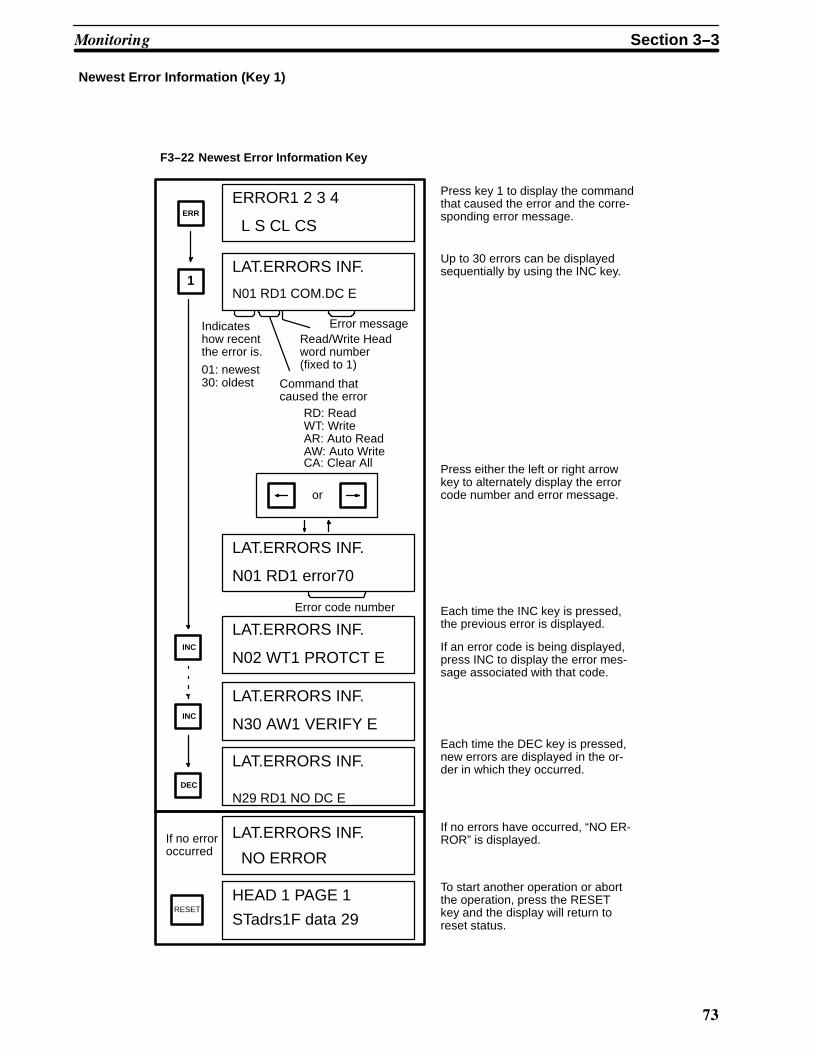
�
Newest Error Information (Key 1)
HEAD 1 PAGE 1
STadrs1F data 29
RD: ReadWT: WriteAR: Auto ReadAW: Auto Write
LAT.ERRORS INF.
N01 RD1 COM.DC E
ERROR1 2 3 4
L S CL CS
DEC
INC
INC
1
RESET
ERR
If no erroroccurred
Indicateshow recentthe error is.
01: newest30: oldest
Error messageRead/Write Headword number(fixed to 1)
Command thatcaused the error
or
LAT.ERRORS INF.
N01 RD1 error70
Error code number
LAT.ERRORS INF.
N02 WT1 PROTCT E
LAT.ERRORS INF.
N30 AW1 VERIFY E
LAT.ERRORS INF.
N29 RD1 NO DC E
LAT.ERRORS INF.
NO ERROR
Press key 1 to display the commandthat caused the error and the corre-sponding error message.
Up to 30 errors can be displayedsequentially by using the INC key.
Press either the left or right arrowkey to alternately display the errorcode number and error message.
Each time the INC key is pressed,the previous error is displayed.
If an error code is being displayed,press INC to display the error mes-sage associated with that code.
Each time the DEC key is pressed,new errors are displayed in the or-der in which they occurred.
If no errors have occurred, “NO ER-ROR” is displayed.
To start another operation or abortthe operation, press the RESETkey and the display will return toreset status.
F3--22 Newest Error Information Key
CA: Clear All
!� �� � Section 3--3

�#
Statistical Error Information (Key 2)
STA.ERRORS INF.
S152 1 PROTCT E
STA.ERRORS INF.
S 9 1 COM.DC E
ERROR1 2 3 4
L S CL CS
DEC
INC
INC
2
ERR
Error message
R/W Head wordnumber (fixed to 1)
or
STA.ERRORS INF.
S 9 1 error70
Error code number
STA.ERRORS INF.
MCBF S 1357
STA.ERRORS INF.
90-09-05
Year Month Day
INC
Number oftimes an er-ror occurred
“S” =“Statistical”
STA.ERRORS INF.
S152 1 PROTCT E
Mean Cycle Be-tween Failures
“S” = “statistical”
MCBF (1 through9999999)
The date is displayed first. This datewas previously registered by theuser as the date from which errorswere to be monitored.
Up to 999 errors can be displayed.If 1000 errors have occurred, the1000th error is displayed as 999.
Press the INC key to display thenumber of times an error has oc-curred, the error message, and theR/W Head word number.
Press the left or right arrow key toalternately display the error codenumber and error message.
If an error code is being displayed,as in the example shown at left,press the INC key again to displaythe error message for the same er-ror. Press the INC key once moreto display the next error code andmessage.
After all messages have been dis-played, press the INC key to dis-play the MCBF. The MCBF value iscalculated using the following ex-pression: Total number
of commandsTotal numberof errors
MCBF value =
If the MCBF value is 9999999 ormore, “9999999” will be displayed.
(The MCBF is rounded off.)
Press the DEC key to display theprevious screen.
F3--23 Statistical Error Information
Press key 2 to display the statisticalerror information.
!� �� � Section 3--3

�0
STA.ERRORS INF.
NO ERROR
HEAD 1 PAGE 1
STadrs1F data 29RESET
If an er-ror didnot occur
If no errors have occurred, this mes-sage will be displayed.
To start another operation or abortthe Error Log operation, press theRESET key and the display will re-turn to reset status.
3--3--10 Error Codes
T3--6 Error Codes
Error codenumber
Error name Error message
70 Data Carrier communication error COM. DC E
71 Data verification error VERIFY E
72 No Data Carrier error NO DC E
7A Data Carrier address over ADRS E
7C Read/Write Head disconnect error R/W H E
7D Write protect error PROTCT E
3--4 Timing ConsiderationsThis section covers timing considerations such as the time required for pro-cessing and turnaround time, which is the time required by the PC to retrievea command and complete the reading/writing of data from/to the Data Carri-er.
Use the tables and graphs that follow to calculate the amount of time re-quired for executing commands involving data communications between theID Sensor Unit and Data Carrier.
3--4--1 Command Processing TimeCommand Processing Time is the time required for data communication be-tween the CPU, ID Sensor, and Data Carrier. Table T3--7 and Figure F3--24show the processing times required for the communication of various quanti-ties of data.
T3--7 ID Sensor Command Processing Time
Command Bytes
1 4 8 16 32 64 128 256 502 2K
Read/Write (includingAuto Read/Write) (ms)
110 115 125 145 220 370 660 1240 2400 ------
Clear-all (ms) ------ ------ ------ ------ ------ ------ ------ ------ ------ 9505
The following graphs show the relationship between the quantity of data tobe processed and the time required for processing a command.
�� � �� ������ � Section 3--4

�1
Processingtime (ms)
2,000
6,0004,000
1,000
600400
2001006040
2010
1 2 4 6 10 40 60100 200 50020
Quantity of data (bytes)
F3--24 Command Processing Time Graph
3--4--2 Turnaround Timeurnaround time (TAT) is the elapsed time from the retrieval of a command bythe PC until the data has been read from or written to the Data Carrier. Tur-naround time can be calculated as follows:
TAT = Coefficient x PC scan time + Command processing time (+ Remote I/Ocommunication time, if applicable)
Coefficient: Differs according to the number of bytes to be read/written andthe I/O refresh time.
PC scan time: The time required by the CPU to scan the program, refreshthe I/O area, etc. Determine this value by referring to Table T3--1 PC ScanTime Coefficients.
Command processing time: The time required to process the communicationbetween the ID Sensor Unit and the Data Carrier. Determine this value byreferring to Section 3--4--1 Command Processing Time.
Remote I/O communication time: additional time required if the ID SensorUnit is mounted to a Remote I/O Slave Rack. If the ID Sensor Unit is notmounted to a Remote I/O Slave Rack, this time is zero.
The timing charts and program examples presented in this section assumethe following conditions:
1, 2, 3... 1. The ID Sensor Unit is set for two-word operation (words 000 and 001;refer to Section 2-1 DIP Switch Setting) and the Intelligent I/O Read/Write instructions are being used.
2. Data sent from the ID Sensor Unit to the PC is stored in the DM area ofthe PC.
If Intelligent I/O Read/Write instructions are not provided with your PC, the IDSensor Unit must be set for four-word operation. Transfer data on a word-by-word basis by executing MOV.
Note that MOV can be executed only once during each scan. Therefore,when using MOV, the number of scans must equal the number of words to betransferred.
�� � �� ������ � Section 3--4

��
T3--1 PC Scan Time Coefficients
No. ofintelligent
instructions
1 2 3 4 5
No. of bytes 1 to 502 503 to 1,004 1,005 to 1,506 1,507 to 2,008 2,009 to 2,042
WriteAuto WriteReadAuto Read
min 3 to max 5 min 6 to max 9 min 9 to max 13 min 12 to max 17 min 15 to max 21
Clear-all 3 to 5* ------ ------ ------ ------
*The Clear-all command can clear up to 2,046 bytes when the Intelligent I/O Instruction is executed once.
Note The data in this table applies to the program examples given on the following pages.
3--4--3 Program Examples and Timing DiagramsThe following program examples and timing diagrams illustrate the relation-ship between commands, number of bytes transferred, and scan time.
(1) To Write 502 Bytes of Data
00109
Command processing end flag
Execution command
15000 13001
13000
00109
00003
DIFU (13) 15000
13000
WRIT(87)#0255DM 1000000
2550613001
Equal flag
Command processing end flag reset
Command transfer start
Command transfer in progress
Command transfer
Command transfer end
F3--25 Writing 502 Bytes of Data
Write and Auto WriteCommands
�� � �� ������ � Section 3--4

�'
Minimum Scan Time
CPU of PC
Execution command
Command transfer
(execution of WRIT(87))
Read data(from common memory to ID)
Data Carrier read/write
in progress (00108)
Command processing
end flag (00109)
command processing end
flag reset bit (00003)
I/O refresh
Read to CPU
Read to CPU Read to CPU
(1)
Scan time
(2)
Output from CPU
(3)
F3--26 Minimum Scan Time; Write and Auto Write
Maximum Scan Time
CPU of PC
Execution command
Command transfer(execution of WRIT(87))
Read data(from common memory to ID)
Data Carrier read/write
in progress (00108)
Command processing
end flag (00109)
command processing end
flag reset bit (00003)
Scan time
(1)
I/O refresh
Read to CPU
(2) (3) (4)
Output from CPU
(5)
Read to CPU
Read to CPU
F3--27 Maximum Scan Time; Write and Auto Write
�� � �� ������ � Section 3--4

�(
Note The processing time of the Write command varies according to the quantityof data to be written. Therefore, TAT varies according to what point during ascan the command processing end flag (00109) is set to ON.
15000
13000
DIFU (13) 15001
00003
13001
13002 1300
3
1300
5
Execution commandDIFU (13) 15000
13000
0010
9
000
13001
13001
13002
1300313002
1500
1
13104
13004 0010
9
000
13005
13005
13006
1300713006
1500
1
Command processing end
Command processing end flag reset
Command A transfer start
Command A transfer in progress
Command A transfer
Command A transfer end
Command A processing in progress
Command A processing end
(command B transfer start)
Command B transfer in progress
Command B transfer
Command B transfer end
Command B processing in prog-
ress
Command B processing end
2550
6
1300
4
2550
6
0010
9
(command processing end flag)
Reset
WRIT(87)
#025
5DM 1000
KEEP(11)
1300
3
WRIT(87)
#025
5DM 1255
KEEP(11)
1300
7
Equal flag
Equal flag
F3--28 Writing 1,004 Bytes of Data
�� � �� ������ � Section 3--4

'*
Minimum Scan Time
CPU of PC
Execution command
Command A transfer
(execution of WRIT(87))
Command A processing
in progress (13002)
Read data (common
memory to ID)
Data Carrier read/write in
progress (00108)
Command processing
end flag (00109)
command processing end
flag reset bit (00003)
Command A processing
end (13003)
Command B transfer
(execution of WRIT(87))
Command B processing
in progress (13006)
Command B processing
end (13007)
I/O refresh Scan time
Read to CPU
(1) (2)
Output
from CPU
Read
to CPU
(3) (4) (5) (6)
Read to CPU Read to
CPU
Read to CPU
Output
from CPU
Read
to CPU
Read
to CPU
F3--29 Minimum Scan Time
�� � �� ������ � Section 3--4
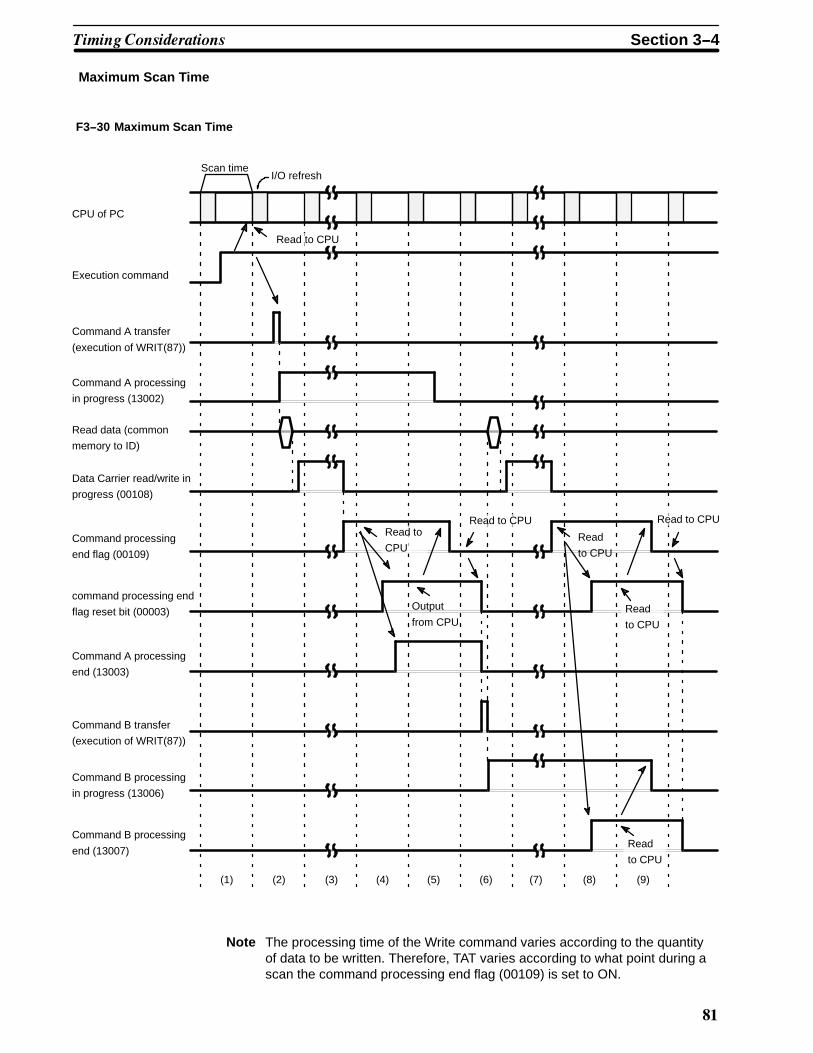
'�
Maximum Scan Time
CPU of PC
Execution command
Command A transfer
(execution of WRIT(87))
Command A processing
in progress (13002)
Read data (common
memory to ID)
Data Carrier read/write in
progress (00108)
Command processing
end flag (00109)
command processing end
flag reset bit (00003)
Command A processing
end (13003)
Command B transfer
(execution of WRIT(87))
Command B processing
in progress (13006)
Command B processing
end (13007)
Scan timeI/O refresh
Read to CPU
Read to
CPURead
to CPU
Read to CPURead to CPU
Read
to CPU
Read
to CPU
Output
from CPU
(1) (2) (3) (4) (5) (6) (7) (8) (9)
F3--30 Maximum Scan Time
Note The processing time of the Write command varies according to the quantityof data to be written. Therefore, TAT varies according to what point during ascan the command processing end flag (00109) is set to ON.
�� � �� ������ � Section 3--4

'�
Read and Auto Read Commands
00109
Command processing end flag
Execution command
15000
14000
00109
00003
DIFU (13) 15000
14000
WRIT(87)#0005DM 3000000
2550614001
Equal flag
Command processing end flag reset
Command transfer start
Command transfer in progress
Command transfer
Command transfer end
14001 14003
14002
14002
#0255
DM 2000001
2550614003
Equal flag
14001
READ(88)
Data read in progress
Data read
Data read end
F3--31 Reading 502 Bytes of Data
�� � �� ������ � Section 3--4

'
Minimum Scan Time
CPU of PC
Execution command
Command transfer(execution of WRIT(87))
Read data(from common memory to ID)
Data Carrier read/write
in progress (00108)
Write data (ID to common
memory)
Command processing end flag
(00109)
command processing end flag
reset bit (00003)
Data read (execution of READ
(88))
I/O refreshScan time
Read to CPU
Output from CPU
Read to CPURead to CPU
(1) (2) (3)
F3--32 Minimum Scan Time
�� � �� ������ � Section 3--4

'#
Maximum Scan Time
CPU of PC
Execution command
Command transfer(execution of WRIT(87))
Read data(from common memory to ID)
Data Carrier read/write
in progress (00108)
Write data (ID to common
memory)
Command processing end flag
(00109)
command processing end flag
reset bit (00003)
Data read (execution of READ
(88))
I/O refreshScan time
Read to CPU
Output from
CPU
Read to CPURead to CPU
(1) (2) (3) (4) (5)
F3--33 Maximum Scan Time
Note The processing time of the Read command varies according to the quantityof data to be written. Therefore, TAT varies according to what point during ascan the command processing end flag (00109) is set to ON.
�� � �� ������ � Section 3--4

'0
15000
14000
DIFU (13) 15000
00003
14001
Execution command
14000
0010
9
000
140012550
6
0010
9(command processing end flag)
WRIT(87)
#000
5DM 1000
Equal flag14001
14002
1400314002
001
140032550
6
READ(88)
#025
5
DM 2000
Equal flag
14003
14004
1400514004
0010
9
000
140052550
6
WRIT(87)
#000
5DM 1005
Equal flag
14005
14006
1400714006
140072550
6Equal flag
001
READ(88)
#025
5
DM 1255
Command processing end flag reset
Command transfer start
Command A transfer in progress
Command A transfer
Command A transfer end
Data A read in progress
Data A read
Data A read end (command B transfer start)
Command B transfer in progress
Command B transfer
Command B transfer end
Data B read in progress
Data B read
Data B read end
F3--34 Reading 1,004 Bytes of Data
�� � �� ������ � Section 3--4

'1
Minimum Scan Time
CPU of PC
Execution command
Command A transfer
(execution of WRIT(87))
Read data (common
memory to ID)
Data Carrier read/write
in progress (00108)
Write data (ID to
common memory)
Command process-
ing end flag (00109)
command processing end
flag reset bit (00003)
Data A read (execution
of READ(88))
Data A read in
progress
(14002)
Command B transfer
(execution of WRIT(87))
Data B read (execution
of READ(88))
Data B read in
progress
(14006)
I/O refresh Scan time
Read to CPU
Output
from CPU
(1) (2) (3) (4) (5) (6)
Output
from CPU
Read to
CPURead to
CPU
Read to CPURead to
CPU
F3--35 Minimum Scan Time
�� � �� ������ � Section 3--4

'�
Maximum Scan Time
CPU of PC
Execution command
Command A transfer
(execution of WRIT(87))
Read data (common
memory to ID)
Data Carrier read/write
in progress (00108)
Write data (ID to
common memory)
Command process-
ing end flag (00109)
command processing end
flag reset bit (00003)
Data A read (execution
of READ(88))
Data A read in
progress
(14002)
Command B transfer
(execution of WRIT(87))
Data B read (execution
of READ(88))
Data B read in
progress
(14006)
I/O refreshScan time
Read to CPU
Output
from CPUOutput
from CPU
Read to
CPU
Read to CPURead to
CPU
Read to
CPU
(1) (2) (3) (4) (5) (6) (7) (8) (9)
F3--36 Maximum Scan Time
Note The processing time of the Read command varies according to the quantityof data to be written. Therefore, TAT varies according to what point during ascan the command processing end flag (00109) is set to ON.
�� � �� ������ � Section 3--4

'(
��� �� #
���$%���&�����"
$"�� ������ ������� ����������� �"�� �� "�� ��� �� ��������� �"� ����)�, �� ��� ��2���� ��� ��� �������� �� �"�� ������� �� ���� � ������ ������� 6���� �� �"�� ������ ��� ���� ��� �( ������ � �����������
/��� ������� �� � "�>���� �� ��1����1� ���������� ��������3 !"�" ��� �"���� �����! �� � ����"�� 2���� �� ���������� ���1�� ���� ���� � ������ �������
���� ������ +��������� &-� � � � � � � � � � � � � � � � � � � � � � � � � � � � � � � � � � � � � � � � � � � � � � � � � � � � � �
���� *"�� $� � �� � +��������� .��� &-� � � � � � � � � � � � � � � � � � � � � � � � � � � � � � � � � � � � � � � � � �
���� �������� ���! �"���� &�� � � � � � � � � � � � � � � � � � � � � � � � � � � � � � � � � � � � � � � � � � � � � � � � � � � �

(*
4--1 Periodic MaintenanceGo over the following checklist monthly to ensure trouble-free operation ofthe ID Sensor system.
T4--1 Monthly Checklist
Condition Checklist Item Standard
Environmental Is the ambient temperature (panel temperature) appropriate? 0# to 55#C
Is the humidity appropriate? 35 to 85%, withoutcondensation
Is there dust on the surface of the Unit? Dust-free
Mounting Is the ID Sensor Unit securely mounted? Must not be loose
Is the cable securely connected? The cable connector must notbe loose
Are there cracks or noticeable weak areas in the cable? Appearance must be normal,free of cracks or exposed wires
4--2 What To Do If a Malfunction OccursTable T4-2 shows causes and corrective actions for particular malfunctions.Refer to this table if you experience trouble with the ID Sensor system.
T4--2 Malfunction Checklist
Error Cause Corrective Action
Allindicators remainunlit.
Power is not applied to the PC. Apply power to the PC. If the indicatorscontinue to remain unlit, make sure the PC isproperly connected to the power supply.
The ID Sensor Unit is not mounted securely. Completely remove the ID Sensor Unit fromthe PC (see note 1) and remount it, makingsure the connecting terminals are secure.
ERRORindicator lights.
The RESET switch is ON. Press the RESET switch (see note 2). If theERROR indicator does not go off, the switch isdefective; replace the Unit.
A WDT (watchdog timer) error has occurred inthe ID Sensor Unit.
Press the RESET switch (see note 2).
CPU ERROR indicator is lit. Locate the cause of the error in the PC andcorrect it.
Note 1. Before removing the ID Sensor Unit from the PC, make sure the power tothe PC is OFF.
2. Do not press the RESET switch while the T/R indicator is lit or while theIntelligent I/O Read Instruction (READ(88)) is being executed; otherwise,the Read/complete flag will turn ON and will not turn OFF, preventing datatransfer. If this occurs, turn the system OFF and then ON again. If the RE-SET switch is pressed while READ(88) is being executed, or if the opera-tion mode of the PC is changed from RUN/MONITOR to PROGRAM whileREAD(88) is being executed, word n+1 bit 02 (ID write end flag) will re-main ON. To turn this flag OFF, either turn the power supply to the PC toOFF and then ON, or turn OFF word n bit 02 (PC read end flag) or word nbit 04 (system reset flag) by performing a forced reset operation with theProgramming Console.
Replacing the Unit Before replacing the ID Sensor Unit, be sure to turn OFF the power to thePC. Remove the Unit and replace it with a new Unit, making sure it is secure-ly mounted. Check the new Unit thoroughly before operation.
When returning a defective Unit to OMRON, include a detailed explanation ofthe problem.
��� �� �� �� � !���� ��� #���� Section 4--2

(�
Spare Parts To minimize downtime of the system, it is advisable to keep at least onespare Unit on hand.
4--3 Diagnostic Flow Charts
If an error occurs, determine the conditions under which it occurs: intermittentor continuing; on-line or off-line.
Use the following flowcharts in Figures F4-1 and F4-2 to determine the causeof an error.
F4--1 Basic Assurance Test (BAT)
START
Turn the power ON
RUN LED
ERR LEDERR LED
SW 1
4-word LED
OK
4-word LED
ERR LED
CPU error LED
Hardware error
Replace the ID
Sensor Unit.
Hardware error
Replace the ID
Sensor Unit.
Correct the
PC error.
lit
unlit
OFF
ON
��� ���� ���� ����� Section 4--3

(�
F4--2 Flowchart for Testing with the Programming
Yes
Connect the Pro-gramming Console
No
Adjust speedof workpiece
1
START
<RUN>
Programming Console inMONITOR
mode?
No
Yes
Hardware errorReplace the IDSensor Unit.
<PROGRAM>MODE ERROR
Turn the power ON
Set the Programming Consoleto MONITOR mode.
<MONITOR>BZ
Execute“TEST AW”
COM. DC E
Yes
No
YesVERIFY E
No
Yes
Yes
Yes
No
No
No
YesYes
No
No
ADRS E
R/W H E
OK
PROTCTE
Hardware errorReplace the IDSensor Unit
Adjust the distance
Workpiece moving toofast? Refer to Section
1-5 Installation.
YesIs distance between R/W Head and
Data Carrier adequate? Refer to Sec-tion 1-5
Installation.
No
Replace R/W Head
Data Carrierdefective?
ReplaceData Carrier.
Is R/W Headdefective?
No No
24 VDC con-nection OK?
Connect24 VDC
Yes
Return to 1
��� ���� ���� ����� Section 4--3

(
Appendix AStandard Models
Name Model Number
ID Sensor Unit C500-IDS01-V1
ID Sensor Unit(long-distance type)
C500-IDS02
Read/Write Head V600-H06
Data Carrier V600-D2KR01
ID Adapter (for IDS02) C500-IDA02
Handheld ProgrammingConsole
C200H-PRO27-E
Connecting Cable (2 m)(See note)
C200H-CN222
Connecting Cable (4 m)(See note)
C200H-CN422
Note The cable connects the Handheld Programming Console to the ID SensorUnit.

(0
Appendix BSpecifications
All Units have the dimensions shown in the following figures.
250
7334.5
Mounted Dimensions(millimeters)
115
Approx. 170
Backplane
Connectioncables
Note Before mounting the ID Sensor Unit, verify the depth of the control panel.
Dimensions ID Sensor UnitC500-IDS01-V1/IDS02IDAdapter C500-IDA02(millimeters)

��������� � Appendix B
(1
Data Carrier V600-D2KR01(millimeters)
44�0.2
54
20
10
531
86
76 �0.2 5 4.5 mm dia.(Four holes)
Read/Write Head V600-H06(millimeters)
60�0.2
70
30
20
532
100
43
14
90 �0.2 5
Power indicator
4.5 mm dia.(Four holes)
BushingCable (6 mm dia.)
(7/0.12 dia.), 8-conductorLength: 10 m Connector
11
ID Sensor Unit Specifications
Ratings All ratings conform to those of C-series Programmable Controllers.

Appendix B��������� �
(�
Characteristics
Item Specifications
Communication ControlProcedure
Interactive
Number of Read/WriteHeads connected
One per ID Sensor Unit
Data Carrier 2K bytes RAM (with built-in battery)
Data Carrier memory format 8-bit
Commands Read, Write, Auto Read, Auto Write, Clear-all, and Auto Read/WriteAbort
Data transferableper instruction
Up to 251 words (502 bytes) can be transferred with WRIT(87) andREAD(88) (see note 1).
Diagnostic functions • CPU watchdog timer• Communication errors
Six communication errors identify causes of errors that haveoccurred during communication between the Data Carrier and theID Sensor Unit. (i.e. Data Carrier missing, communication error)
• Error logThe error log function allows communication errors to be displayedin statistical form or in order of occurrence. Errors are retained bythe backup capacitor.
Monitoring functions The following monitoring functions are available when the ID SensorUnit is connected to a Handheld Programming Console. (Use thekeyboard sheet provided with the ID Sensor Unit.) (Cable length: 4 mmax.)Read (1 byte)Step Write (1 byte)Continuous WriteTestError Log
Memory backup Error information is backed up by a capacitor for 15 days (at 25#C;see note 2).
Number of words required 2 words when using WRIT(87) and READ(88);4 words when using MOV (DIP switch-selectable)
Internal currentconsumption
400 mA max. at 5 VDC.
External current supply 250 mA max. at 24 VDC (to drive R/W Head)
Dimensions 34.5(W)x250(H)x93(D) mm
Weight 700 grams max.
Note 1. WRIT(87) and READ(88) are actually capable of transferring 255 words,but, as 4 words are used for command codes, in practice only 251 wordsare available for data transfer.
2. The error information stored in the memory of the ID Sensor Unit is re-tained by a built-in backup capacitor for 15 days at an ambient tempera-ture of 258C. As shown in the following diagram, the duration of thebackup shortens as the temperature rises.

��������� � Appendix B
('
25 30 40 50 600
2
5
10
15Backupperiod(days)
Ambient temperature(#C)
Internal Circuit Block for ID Sensor UnitsC500-IDS01-V1
PC CPU
I/O Bus
Interface
circuit
Common
memory
(see note 1)
I/O word data
(see note 2)
I/O
LED indicators
CPU
Switches
System
memory
Work
memory
Communication
interface for R/
W Head
Handheld
Programming
Console connector
R/W Head
connector
C500-IDS02
PC CPU
I/O Bus
Interface
circuit
Common
memory
(see note 1)
I/O word data
(see note 2)
I/O
LED indicators Switches
CPU
System
memory
Work
memory
Handheld
Programming
Console connector
Communication
interface for
RS-485
ID Adapter
connector for
RS-485
Note 1. The common memory is read from and written to by the WRIT(87) andREAD(88) instructions.
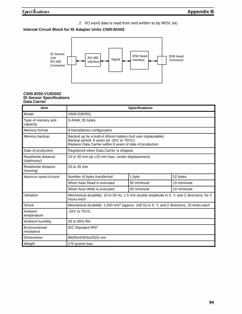
Appendix B��������� �
((
2. I/O word data is read from and written to by MOV, etc.
Internal Circuit Block for ID Adapter Units C500-IDA02
ID SensorUnitRS-485Connector
RS-485interface
R/W HeadinterfaceSignal
R/W HeadConnector
C500-IDS0-V1/IDS02ID Sensor SpecificationsData Carrier
Item Specifications
Model V600-D2KR01
Type of memory andcapacity
S-RAM, 2K bytes
Memory format 8 bits/address configuration
Memory backup Backed up by a built-in lithium battery (not user-replaceable)Backup period: 8 years (at -25# to 70#C)Replace Data Carrier within 8 years of date of production.
Date of production Registered when Data Carrier is shipped.
Read/write distance(stationary)
10 to 35 mm (at $10 mm max. center displacement)
Read/write distance(moving)
20 to 35 mm
Maximum speed of travel Number of bytes transferred 1 byte 32 bytes
When Auto Read is executed 50 m/minute 15 m/minute
When Auto Write is executed 30 m/minute 10 m/minute
Vibration Mechanical durability: 10 to 55 Hz, 1.5 mm double amplitude in X, Y, and Z directions, for 2hours each
Shock Mechanical durability: 1,000 m/s2 (approx. 100 G) in X, Y, and Z directions, 10 times each
Ambienttemperature
-25# to 70#C
Ambient humidity 35 to 95% RH
Environmentalresistance
IEC Standard IP67
Dimensions 86(W)x54(H)x20(D) mm
Weight 170 grams max.

��������� � Appendix B
�**
Read/Write Head
Item Specifications
Model V600-H06
Insulation resistance 50 M* (at 500 VDC) between cable terminals and housing
Dielectric strength 500 VAC 50/60 Hz for 1 minute between cable terminals and housing
Vibration Mechanical durability: 10 to 55 Hz, 1.5 mm double amplitude in X, Y, and Z directions, for 2hours each
Shock Mechanical durability: 1,000 m/s2 (approx. 100 G) in X, Y, and Z directions, 10 times each
Ambient operatingtemperature
-25# to 70#C
Humidity 35 to 95% RH
Environmentalresistance
IEC Standard IP67
Dimensions 100(W)x70(H)x30(D) mm
Cable length 10 m
Weight 350 grams max. (Read/Write Head only)1 kilogram max. (including cable)
ID Adapter Specifications
Ratings All ratings conform to those of all C-series Programmable Controllers.
Characteristics
Item Specifications
Number of words occupied No I/O word is occupied
Power for external supply 24 VDC 450 mA max.
Internal current consumption 5 VDC is not consumed
Dimensions 34.5(W)x250(H)x93(D) mm
Weight 550 grams max.

�*�
Appendix CASCII Conversions
This appendix gives data conversions for ASCII characters. The decimal, binary and hexadecimal equivalentsare given.
Extended ASCII to Binary and HexadecimalThe following table gives the conversions for the standard ASCII character set to both binary and hexadeci-mal. In the Programmable Controller, all ASCII data is stored in it’s hexadecimal equivalent.
Bits 0 to 3 Bits 4 to 7
BIN 0010 0011 0100 0101 0110 0111 1010 1011 1100 1101 1110 1111
HEX 2 3 4 5 6 7 A B C D E F
0000 0 Space � � � � � � � � � �
0001 1 � � � � � � � �
0010 2 � � � � � � � � � �
0011 3 � � � � � � � � � � � �
0100 4 � � � � � � � � � � � �
0101 5 � � ! " # � � � ! "
0110 6 $ % & ' ( ) # $ % & ' (
0111 7 * + , - . / ) * + , - .
1000 8 0 1 2 3 4 5 / 0 1 2 3 4
1001 9 6 7 8 9 : ; 5 6 7 8 9 :
1010 A < = > ? @ A ; < = > ? @
1011 B B C D E F G A B C D E F
1100 C H I J K L M G H I J K L
1101 D N O P Q R S M N O P Q R
1110 E T U V W X Y S T U V W
1111 F Z [ \ ] ^ _ X Y Z [ \ _

$���� �� %��� � Appendix C
�*�
ASCII to DecimalThe following table gives the decimal equivalents of the range of English language ASCII characters. The Pro-grammable Controller stores ASCII data in hexadecimal form. Care should be taken when inputting ASCIIdata in equivalent forms.
ASCII Decimal ASCII Decimal ASCII Decimal ASCII Decimal ASCII Decimal ASCII Decimal
Space 32 0 48 @ 64 P 80 ‘ 96 p 112
! 33 1 49 A 65 Q 81 a 97 q 113
” 34 2 50 B 66 R 82 b 98 r 114
# 35 3 51 C 67 S 83 c 99 s 115
$ 36 4 52 D 68 T 84 d 100 t 116
% 37 5 53 E 69 U 85 e 101 u 117
& 38 6 54 F 70 V 86 f 102 v 118
’ 39 7 55 G 71 W 87 g 103 w 119
( 40 8 56 H 72 X 88 h 104 x 120
) 41 9 57 I 73 Y 89 i 105 y 121
* 42 : 58 J 74 Z 90 j 106 z 122
+ 43 ; 59 K 75 [ 91 k 107 { 123
, 44 < 60 L 76 \ 92 l 108 | 124
- 45 = 61 M 77 ] 93 m 109 } 125
. 46 > 62 N 78 ^ 94 n 110 « 126
/ 47 ? 63 O 79 _ 95 o 111 ~ 127

�*
Glossary
ASCII code [A(merican) S(tandard) C(ode for) I(nformation) I(nterchange)] A standardcomputer code used to facilitate the interchange of information among vari-ous types of data-processing equipment.
Backplane A base to which Units are mounted to form a Rack. Backplanes provide aseries of connectors for these Units along with wiring to connect them to theCPU and Power Supply. Backplanes also provide connectors used for con-nection to other Backplanes. In some Systems, different Backplanes areused for different Racks; in other Systems, Racks differ only by the Unitsmounted to them.
backup A copy of existing data which is valuable if the original data is accidentallyerased.
bit The smallest piece of information that can be represented on a computer. Abit has the value of either zero or one, corresponding to the electrical signalsON and OFF. A bit is one binary digit.
central processing unit A device that is capable of storing a program and data, and executing the setof instructions contained in the program. In a PC System, the central pro-cessing unit executes the program, processes I/O signals, communicateswith external devices, etc.
center displacement In this manual, center displacement refers to the degree of misalignment ofthe center points of the Data Carrier and the Read/Write Head at which datacommunication is still possible.
CPU An acronym for central processing unit.
CPU Backplane A Backplane used to create a CPU Rack.
CPU Rack Part of a Rack PC, the CPU Rack contains the CPU, a Power Supply, andother Units.
Expansion I/O Unit An I/O Unit for a Package-type PC that provides more I/O points to the PC.
flag A bit that is turned ON and OFF automatically by the system in order to pro-vide status information.
hexadecimal A number system used to represent numbers in base 16 with digits0,1,2...9,A,B...F.
&������
�*#
Intelligent I/O Unit A Unit, such as an ASCII Unit or Ladder Program I/O Unit, that is equippedwith its own CPU and can be programmed.
I/O devices The devices which are connected to the terminals on I/O Units, Special I/OUnits, or Intelligent I/O Units. I/O devices may be part of the Control System ifthey function to help control other devices, or they may be part of the con-trolled system if they interact directly with it.
I/O Unit The most basic type of Unit mounted to a Backplane. I/O Units include InputUnits and Output Units, each of which is available in a range of specifica-tions. I/O Units do not include Special I/O Units, Link Units, etc.
PC An acronym for Programmable Controller.
Power Supply A Unit that mounts to a Backplane in a Rack PC. It provides power at thevoltage required by the other Units on the Rack.
Programmable Controller A small, computer-like device that can control peripheral equipment, such asan electric door or quality control devices, based on programming and pe-ripheral input devices. Any process that can be controlled using electricalsignals can be controlled by a PC. PCs can be used independently or net-worked together into a system to control more complex operations.
register/registered Storing text and graphics in the RAM/ROM card from a personal computer orthe ASCII Unit. Graphics that have been written to the RAM/ROM card arereferred to as registered messages.
Remote I/O Slave Rack A Backplane to which is mounted a Remote I/O Slave Unit. This Rack can belocated a considerable distance from the CPU Rack, with the only connectionbeing a cable connecting the Slave to a Remote I/O Master Unit mounted onthe CPU Rack or on an Expansion I/O Rack.
Remote I/O Slave Unit A Remote I/O Unit that is accessed through a Remote I/O Master Unit.
Remote I/O Unit A Unit that extends the distance an Expansion I/O Rack can be from theCPU.
RS--485 interface An industry standard connector for serial communications.
scan time The time the PC requires to perform internal operations such as resetting thewatchdog timer, reading the program, receiving input data, sending outputdata, and executing instructions. Scan time is monitored by the watchdogtimer within the PC. If scan time takes longer than specified, an error mes-sage may be generated, or the CPU may stop. Scan times differ according to

&������
�*0
the configuration of the system.
Special I/O Unit A dedicated Unit that is designed for a specific purpose. Special I/O Unitsinclude Position Control Units, High-speed Counters, Analog I/O Units, etc.
system configuration The arrangement in which Units in a System are connected. This term refersto the arrangement and wiring of all the devices needed to compose the Sys-tem. In OMRON terminology, “system configuration” describes the arrange-ment and connection of the Units comprising a Control System that includesone or more PCs.
Unit In OMRON PC terminology, the word Unit is capitalized to indicate any prod-uct sold for a PC System. Though most of the names of these products in-clude the word Unit, this is not always so; for example, a Remote Terminal isreferred to as a Unit. Context generally makes the meaning of this wordclear.
word In digital circuits, a group of bits. Usually a word consists of four, eight, orsixteen bits. In C-series PCs, a word consists of sixteen bits. Words can beused to store data, or they can be used for I/O.
work bits Bits in the IR area that are not being used for input or output. These bits canbe used in the program in any way desired.
write protection Write protection is a means of ensuring that specified information written tothe Data Carrier cannot be altered or erased.

�*�
���+
'��(��
% &'� ����� ���� ���������� (
$
������ ��� ������ )*��������� )*������� )*
������ ��� ������� ���������� )+
������,���� �������� )+
�������� ������� )%
�-&.. ���� ��� +%� +(���� ��� �������� +/���� ���,0��� ����� �������� +1���� 0���� +)&������� �������� +/
)
2���� �������� 3�� 42�35� 6*
��� ������������������� ������� 7%�������� ������� 78
��99�� )8
�
����� �-��%1(� **
���� ���������� �� :��� &����� ��� �,0 '��� �� 1
���!����� 68
������� ����!�� �������� 61
���������� /)
������� ��������� ���� /(� /)
��������� +
������ ������ 61
������������� ��������� +7;+/� ������ ���� 1� ��������� <���� 4�������� ������5� %6������ ��������� 17
���� ���,0��� ������ ������ 0���� 1� ��������� <���� 4�������� ������5� %(������ �������� //
&�������� ��������� <���� 4�������� ������5� %)
��= 4���5� ������� <���� 4��������� ������5� (%��= 4����5� ������� <���� 4��������� ������5� (7���� ��������� <���� 4�������� ������5� %1������ ��������� 17
0���� ��������� <���� 4�������� ������5� %%������ �������� //
������� �� �� :��� &������ 76;+8
�������������� =)88,)78 .: &���������� +
��������� ��� ����������� %;*(
&��������� 0���� )/
&>?� %(� %)� %/� (/� (1
������������� ����� 76
.�������� .,� ���,0��� ������������ *6
�������� ������� 76
������ ���� �� :��� &������ ��� +8
������� �� �� :��� &������ 76� ��
�
:��� &�����
������ ��� ������� )*
��������� 7;*(
��� �� ����� 1
���� ���������
��������� ������� ��� 71
�������� ������� 7+
���� ������� )(
��� �� ����������
&������� �������� ++
������������ %7
������� ��������� +
���������� ���� ������� 6*
������������� ������������ 71
���������
:��� &����� =)88�:7@�8*� 6)
.: �������� 6(
.: -������ 6(
������ .: -����,.: ������� 6(
���,0��� '�� =)88�'8)� 6)
:.> ������ ������� *1
:.> �������� �
������� ���� :��� &����� ��� �,0 '��� /� 1
�
������� � :��� &����� �� �,0 '�� �� � ������� ������ 6
������,A����� �������� *1
����� ����� ���� ���������� (
����� ���� ������������ /+
���� ������������ ������� +� /8
���� B :� 68
���� ��� �������� /8
������ +8� ()� 68
���� ����� /(
���� ������ 78
������ ���� �� :��� &������ +*
� ���
�*'
�
���� ���������
��������� ������� 7(� ��
�������� ������� 78
���� ��������
��������� ������� ��
�������� ������� ��� 77
&
C�������� *8+
*
'<�������� +%� )(
���� ��� �������� +/
���� 0���� +)
��� �������� +(
0��� �������� +%
��������� 68
�
.: ������� ����� ���� &(88��.:�87� )
.: -���� �����
&(88��.:-8*��=*� �
����������� 7
.: -���� ?���
D���� ���� &(88��.:-87� (
D���� ���� &(88.:-�8*�=*� %
����� (/
��������� 68
��������� ����
������� *1
��������� *1
���������� ��� ���������� %;*(
.������������ :��� &������ �,0 ���� �,0 ������� /;*(
������������� /
.�������� .,� ���,0���� +
������������ *6
:.> ������ �������� *1
.�������� .,� ���,0��� .����������� � - 3 ������� 68
.�������� .,� ���,0��� .������������ 78� 77
������������ *6
������������� ��������� ++
������ 7*
��� �������� 76
������� ������� ����!�� 61;66
+
A�2 ��������� )*
,
������� �� �������� *1
��������� .: -����� 7
!
���������� 68
������������ ���!����� 68
��� &��� 2��� D������� /8� /%
������� ����� �� .3��� ��������� ��� ��������� (6
������� ���� )1
����������� ();)/
������,���� ������� )+
�������� ������� )%
���� ������� )(
� �:� )+� )(
����� ��� �� �������� �������� )%
����� �������������� )
3 -3� )+
0�.3 *� )+
0�.3 7� )+
��=� /)
������������ *6
��= ������������ 78
������ ��������� :��� &������ ��� �,0 '���� 6
'
���� ���� ������������ /8� /+
�������� /*
���� ���� ����������� !�� /+
�
������� ���������� 68
���� ������� 7% =:&� **
����� ����� %� (
����� ����� .: ������� )
������� <�����
�������� ������� %%
0���� ���� 0���� ��� &�������� %%;%1
>���������� &��������� )
�������������� 7;*(
��������� ��� *8;*+
���� ���������� ��������� ������� 71
���� ���������� �������� ������� 7+
.,� ������ ���� 7(
����� �� ������ *6
������� 71
��� �������� 76
�����������
������� <������ +*
������� ����� +*
������ ��������� //
>���������� &�����
���������� ()
!� ������� (/
!������ ���� ()
��� ������ ������� (/
��� ������� (/
����
�� .3��� (1
>��C���� (1
�? � (1
�� .3��
������� �������� )8
� - 3 �������� )8

� ���
�*(
-
�,0 '��� ��������� 7;*(
�������� 6)
� �:4115������������ *6:.> -����� �������� *1
����������� ���� ��� �� :��� &����� ��� �������� �������
���� .,� &������������ 3��� /)
���� .,� -�� ���!� *6������������� ���� /):.> ������ �������� *1.,� ������ ���� 7(������� 71������� ���� (*
���� .,� ������� ���� (*
�������� �� ?���� 68
� - 3� 7)� 68
���� &>?,.: -����� 76
� - 3 ������� ����� ����� %� (
�������� �� .: -���� ?���� 68
�-��%1( �������� (� **����� ����� )
�? � ����� ���� ���������� (
�
���� ���� /)
���� ��� ����������� ��
���� ������ 6*
�������������� 6(��������������� 6/�������� 6)
�������� ������ 6+
����� ��� �� �������� �������� )%
����������� ���� ������������ /8� /%�������� /7
��� ����� ))
����� ��������������� );*(
����� ���������� *8;*+
�
3,�� ����� ���� ���������� (
��������� 68
���� ����������� /)
���������� ���� /)� /6� 1*� 1/
��������,��������� �������� *6
�
��� �������� 76
.
=)88,)78 .: &���������� ������� �������������� +
�������� ����� 7)� 68����� 7*
0:3� ��� �������� ����
������&(88�.:-8*=*� *8&(88�.:-87� **�������� �-��%1( ����� **;*(�-��%1( ����� **
����� ������ )*� /%
���!���� )
0�.341/5������������ *6:.> ������ ������� *1
���� ���������� +1;%8�������� +6�������� +1<������ +6;%*
OMRON Sales Offices
���
�������
BRASIL
OMRON ELECTRÔNICA DO BRASIL LTDA.Rua Acruas, 220--Jd. Aeroporto CEP 04612--São PauloTel: (11)542--1611/Fax: (11)241--0736Tlx: 1154121 OMRO BR
CANADA
OMRON CANADA INC.350 Middlefield Road, Scarborough, Ontario M1S 5B1Tel: (416)298--9988/Fax: (416)293--1816/Tlx: 065--25360
Montreal
OMRON CANADA INC. (Regional Office)227 Place, Frontenac, Pointe Claire, Quebec H9R 4Z7Tel: (514)694--6361
U.S.A.
OMRON ELECTRONICS INC.1 East Commerce Drive, Schaumburg, IL 60173Tel: (708)843--7900/Fax: (708)843--8568Tlx: 910--291--0426 OMRONELEC SHBU
Atlanta
3300 N.E. Expressway, Suite 3W Atlanta, GA 30341Tel: (404)451--2370/Fax: (404)451--7504
Boston
175 Andover Street, Danvers, MA, 01923Tel: (617)774--6501/Fax: (617)774--310
Cincinnati
4350 Glendale--Miford Road Suite 110 Cincinnati, OH45242Tel: (513)733--8334/Fax: (513)733--8363
Los Angeles
2050 S. Santa Cruz st. Suite 110 Anaheim, CA 92805Tel: (714)978--6008/Fax: (714)978--0192
Philadelphia
487 Devon Park Drive, Suite 214, Wayne, PA 19087Tel: (215)964--9376/Fax: (215)964--8379
San Francisco
20045 Stevens Creek Blvd. Suite 1B, Cupertino, CA95014Tel: (408)255--9231/Fax: (408)996--3854Tlx: (910)338--0503
������� ���
AUSTRALIA
OMRON ELECTRONICS PTY. LTD.Private Bag No. 12, Frenchs Forest Post OfficeFrenchs Forest, NSW 2086Tel: (02)975--1511/Fax: (02)975--1518
HONG KONGOMRON ELECTRONICS ASIA LTD.Unit 1510--12, Silvercord Tower 130, Canton Road, Tsimshatsui, KowloonTel: 7233827/Fax: 7231475/Tlx: 41092 OMRON HX
INDONESIAP.T. INTERPANCA WIRA DINAMIKAJI. Pinangsia Timur No. 48Jakarta 11110 IndonesiaTel: 6900601 (4 lines)/Fax: 6499080/Tlx: 42951--IA
JAPANOMRON CorporationFA Division H.Q.13F Gotenyama Mori Bldg.4--7--35, Kitashinagawa, Shinagawa--ku,Tokyo 140 JapanTel: (03)5488--3183/Fax: (03)5488--3271
KOREAOMRON KOREA CO., LTD.Room No. 802, New Seoul Bldg., #618--3 Sin Sa--Dong,Kang Nam--Gu SeoulTel: (822)512--0871/Fax: (822)511--9279
MALAYSIAPRECICON SDN BHD9th Fl., West Wing, Wesma Tractors, 7 Jalan SS16/1,Subang Jaya, 47500 Petaling Jaya Selangor Darul Eh-sanTel: 7334450/Fax: 7335303/Tlx: MA36227
NEW ZEALANDCONTROLTECH SYSTEMS LTD.6A Rakino Way, Mt. Wellington, AucklandTel: 60--9650/Fax: 60--9572/Tlx: 21570
PAKISTANKARIKO7, Scotch Corner, Upper Mall LahoreTel: 372536/370748/Tlx: 4944 CTOLH PK
PHILIPPINESP.I. INDUSTRIAL SUPPLY CO., INC.682--684 Rizal Avenue, ManilaTel: 49--86--20/Tlx: 63299 PIELSU PN
SINGAPOREOMRON SINGAPORE (PTE.)LTD.5 Little Road #08--01, Cemtex Industrial Bldg, 1953Tel: 2830006/Fax: 2850682/Tlx: RS23403
TAIWANOMRON TAIWAN ELECTRONICS INC.MAIN OFFICE6F. Home Young Bldg, No. 363, Fu-Shing N. Rd.Taipei, Taiwan, R.O.C.Tel: 2--716--3745/Fax: 2--712--6712
THAILANDOMRON--TRISAK CO., LTD.No. 248 Rachadaphisek Rd. Huay Kwang BangkokTel: 2224380/Fax: 2761966/Tlx: 87133 TRITRAD TH

����� ���� ���� ����������
���
������
AUSTRIAOMRON ELECTRONICS Ges.m.b.H.Camillo Sitte Gasse 6--8, A--1152 WienTel: (0222)9276060/Fax: (0222)9276067/Tlx: 134230
BELGIUMOMRON ELECTERONICS N.V./S.A.Stationsstraat 24, B--1720 Groot--BijgaardenTel: (02)4662480/Fax: (02)4660687/Tlx: 62150
DENMARKOMRON ELECTRONICS A/SGrønrisvejDK-2450 Copenhagen SVTel: 45-36-442111/Fax: 45-36-442188
FINLANDOMRON ELECTRONICS OYMetsanpo jankuja 5SF--02130 ESPOOTel: 001--358--0--460511/Fax: 001--358--0--460136
FRANCEOMRON ELECTRONICS S.a.r.l.19, rue du Bois Galon,BP 3394121 Fontenay--Sous--Bois, CédexTel: (1)48761212/Fax: (1)48760930/Tlx: 264931
GREECEKALAMARAKIS & SAPOUNAS, S.A.10, Great Kydonion Street, GR--111 44 AthensTel: (01)2235511.12/Tlx: 216736
ITALY
OMRON ELECTRONICS S.r.l.Viale Certosa 49, 20149 MilanoTel: (02)32681/Fax: (02)325154
NETHERLANDSOMRON ELECTRONICS B.V.Jan Rebelstraat 4, NL--1069 CB, Amsterdam--OsdorpTel: (020)196363/Fax: (020)198292
NORWAYOMRON ELECTRONICS NORWAY A/SOle Deviks vei 4P.O. Box 109 Bryn, N--0611 OSLO 6NorwayTel: +47(2)65 75 00/Fax: +47(2)65 83 00
PORTUGALOMRON ELECTRONICS LDAAv. Miguel Bombarda 70--2e 1000 LISBONTel: (351)1771170/Fax: (351)1770976
SPAINOMRON ELECTRONICS S.A.c/Arturo Soria 95/99, E--28027 MadridTel: (91)4070211/Fax: (91)4070883Tlx: 49190 OMRES E
SWEDENOMRON ELECTRONICS A.B.Musseronvagen 1C, P.O. Box 1223, S--14125 HuddingeTel: (08)7460040/Fax: (08)7743095/Tlx: 17484
SWITZERLAND
OMRON ELECTRONICS AGGewerbestrasse 7, 6330 ChamTel: (042)416441/Fax: (042)416445/Tlx: 862118
U.K.
IMO PRECISION CONTROLS LTD1000 North Circular Road, Staples Corner GB--LondonNW2 7JPTel: (081)4526444/Fax: (081)4502274/Tlx: 28514
W. GERMANY
OMRON ELECTRONICS G.m.b.H.Oberrather Strasse, 6, D--4000 Düsseldorf 30Tel: (0211)65020/Fax: (0211)6502107 or (0211)6502149Tlx: 8581890
�� �� ��� ������
BAHRAIN
EBRAHIM AL--SHAKAR & SONSManama 304Tel: 254418/Tlx: 8588 ESSCO--BN
IRAN
IRAN BARGH ELECTRICAL CO., LTD.P.O. Box 11365 -- 3517 Tehran 15718Tel: 213261/Tlx: 213636 TPBA IR
KENYA
SWITCHGEAR & CONTROLS, LTD.P.O. Box 42503, NairobiTel: 540381/Tlx: 25522
KUWAIT
AMMAR & PARTNERS ELECTRICAL COP.O. Box 1871, 13019 SafatTel: 817322/Fax: 4841818/Tlx: 44486 APPECO
MOROCCO
MEST COMPOSANTS ELEC.4, Rue De Provins CasablancaTel: 246390/Tlx: 26902 MEST M
SAUDI ARABIA
TAYSEER AL SHEIKH CORPNP.O. Box 19865, Jeddah 21445Tel: 2--6717285/Fax: 2--6721910Tlx: 606292 TAYSCO SJ
TUNISIA
AXAFRICE8, Avenue du Quebec, 1001 TunisTel: 1--255938/Tlx: 14932
TURKEY
TEKNIK MALZEME SATIS VE TICARET A.S.Hayriye Caddesi 16, 80060 Galatasaray, IstanbulTel: 1--1499340/Fax: 1--1430258/Tlx: 1831258
U.A.E.
DEIRA GENERAL MARKETINGP.O. Box 11370, DubaiTel: 224554/Tlx: 48557 DEGAMEM

��
Revision History
A manual revision code appears as a suffix to the catalog number on the front cover of the manual.
Cat. No. W180--E1--1
Revision code
The following table outlines the changes made to the manual during each revision. Page numbers refer toprevious version.
Revisioncode
Date Revised content
1 May,1990 Original production
Dec,1990 Converted to the current format based on the information contained in theoriginal manual. No changes to content were made.