Embed Size (px)
Citation preview

TECHNICAL EDUCATION
JOB AID W10329932
L-84
Vertical Modular Washer
JC-01
TECHNICAL EDUCATION
Built-in Coffee System
JOB AID W10647095
JBC7624BS
ii n Jenn-Air Built-in Coffee System
FORWARD This Jenn-Air Job Aid, "Built-in Coffee System" (Part No. W10647095), provides the In-Home Service Professional with information on the installation, operation, and service of the “Built-in Coffee System."
GOALS AND OBJECTIVESThe goal of this Job Aid is to provide information that will enable the In-Home Service Professional to properly diagnose malfunctions and repair the "Jenn-Air Built-in Coffee System.”
The objectives of this Job Aid are to:• Understand and follow proper safety precautions.• Successfully troubleshoot and diagnose malfunctions.• Successfully perform necessary repairs.• Successfully return the coffee system to its proper operational status.
WHIRLPOOL CORPORATION assumes no responsibility for any repairs made on our products by anyone other than authorized In-Home Service Professionals.
Copyright © 2013, Whirlpool Corporation, Benton Harbor, MI 49022
Jenn-Air Built-in Coffee System n iii
TABLE OF CONTENTS
Jenn-Air Built-in Coffee System
SECTION 1 — GENERAL INFORMATION
COFFEE SYSTEM SAFETY .....................................................................................................................1-2MODEL & SERIAL NUMBER LABEL .....................................................................................................1-3TECH SHEET LOCATION .......................................................................................................................1-3PARTS & FEATURES .............................................................................................................................1-4PRODUCT SPECIFICATIONS ................................................................................................................1-5NOTES .................................................................................................................................................1-6
SECTION 2 — OPERATION
BEFORE USING THE COFFEE SYSTEM .................................................................................................2-2COFFEE SYSTEM USE ...........................................................................................................................2-4SWITCHING ON AND PREHEATING ....................................................................................................2-6MAKING COFFEE OR ESPRESSO USING COFFEE BEANS ....................................................................2-6CHANGING THE AMOUNT OF COFFEE ...............................................................................................2-7ADJUSTING THE COFFEE GRINDER .....................................................................................................2-8MAKING ESPRESSO WITH GROUND COFFEE .....................................................................................2-8MAKING CAPPUCCINO .......................................................................................................................2-8DISPENSING HOT WATER .................................................................................................................2-10COFFEE SYSTEM CARE ......................................................................................................................2-11GENERAL CLEANING .........................................................................................................................2-11VACATION OR STORAGE ...................................................................................................................2-13SWITCHING OFF THE COFFEE SYSTEM .............................................................................................2-13CONSUMER TROUBLESHOOTING .....................................................................................................2-14NOTES ...............................................................................................................................................2-16
SECTION 3 — INSTALLATION
INSTALLATION REQUIREMENTS .........................................................................................................3-2TOOLS AND PARTS ..............................................................................................................................3-2LOCATION REQUIREMENTS ................................................................................................................3-2ELECTRICAL REQUIREMENTS .............................................................................................................3-3INSTALLATION INSTRUCTIONS ...........................................................................................................3-4INSTALL THE MOUNTING BRACKETS .................................................................................................3-4INSTALL THE COFFEE SYSTEM ............................................................................................................3-5COMPLETE INSTALLATION ..................................................................................................................3-6NOTES .................................................................................................................................................3-6
SECTION 4 — COMPONENT ACCESS
COFFEE SYSTEM EXPLODED VIEWS ....................................................................................................4-2COFFEE SYSTEM PARTS LIST ...............................................................................................................4-6JENN-AIR BUILT-IN COFFEE SYSTEM DISASSEMBLY SECTION ...........................................................4-7BEFORE DISASSEMBLING THE COFFEE SYSTEM ................................................................................4-8REMOVING THE FAN PANEL ...............................................................................................................4-9REMOVING THE BACK PANEL & TRAYS ............................................................................................4-10REMOVING THE MAIN BOARD .........................................................................................................4-11REMOVING THE FLOW METER .........................................................................................................4-12REMOVING THE WATER PUMP ........................................................................................................4-13REMOVING THE STEAM HEATER & 3-WAY VALVE ............................................................................4-14
iv n Jenn-Air Built-in Coffee System
PRODUCT SPECIFICATIONS & WARRANTY INFORMATION SOURCES (inside back cover)
STEAM HEATER & 3-WAY VALVE ASSEMBLY .....................................................................................4-15REMOVING THE DIVERTER/TRANSMISSION ASSEMBLY .................................................................4-16DIVERTER/TRANSMISSION ASSEMBLY ............................................................................................4-17REMOVING THE COFFEE HEATER .....................................................................................................4-18COFFEE SYSTEM ASSEMBLY ..............................................................................................................4-19REMOVING THE DISPLAY BOARD & 2-WAY VALVE ...........................................................................4-20REMOVING THE GRINDER ASSEMBLY ..............................................................................................4-24GRINDER ASSEMBLY .........................................................................................................................4-25NOTES ...............................................................................................................................................4-26
SECTION 5 — DIAGNOSTICS & TROUBLESHOOTING
SAFETY WARNINGS ............................................................................................................................5-2CONTROL PANEL .................................................................................................................................5-3TO ENTER LOAD TEST MODE ..............................................................................................................5-3TO ENTER DISPLAY TEST MODE..........................................................................................................5-3CUSTOMER INSTRUCT AND TECHNICAL FAULTS ...............................................................................5-4WIRING DIAGRAM ..............................................................................................................................5-6LADDER DIAGRAM .............................................................................................................................5-7MAIN BOARD ......................................................................................................................................5-8LED-FAN PCB .......................................................................................................................................5-9PLUMBING DIAGRAM.......................................................................................................................5-10MEASURING COFFEE TEMPERATURE ...............................................................................................5-11COMPONENT TESTING CHART .........................................................................................................5-12COFFEE HEATER STRIP CIRCUIT ........................................................................................................5-14COFFEE HEATER NTC STRIP CIRCUIT ................................................................................................5-14STEAM HEATER STRIP CIRCUIT .........................................................................................................5-14STEAM HEATER NTC STRIP CIRCUIT .................................................................................................5-14DIVERTER MOTOR STRIP CIRCUIT ....................................................................................................5-15DIVERTER LIMIT SWITCHES STRIP CIRCUIT .....................................................................................5-152-WAY VALVE STRIP CIRCUIT ............................................................................................................5-153-WAY VALVE STRIP CIRCUIT ............................................................................................................5-15PUMP STRIP CIRCUIT ........................................................................................................................5-16WATER FLOW/SWITCHES STRIP CIRCUIT .........................................................................................5-16GRINDER MOTOR STRIP CIRCUIT .....................................................................................................5-16
GENERAL INFORMATION
Jenn-Air Built-in Coffee System n 1-1
Section 1:General Information
This section provides general safety, parts, and information for the “Jenn-Air Built-in Coffee System.”
Q Coffee System Safety
Q Model & Serial Number Label
Q Tech Sheet Location
Q Parts & Features
Q Product Specifications
Q Notes
1-2 n Jenn-Air Built-in Coffee System
GENERAL INFORMATION
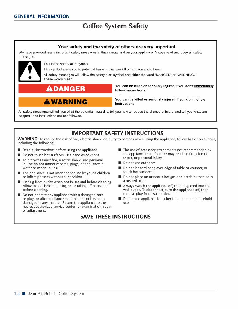
Coffee System Safety
You can be killed or seriously injured if you don't immediately
You can be killed or seriously injured if you don't follow
All safety messages will tell you what the potential hazard is, tell you how to reduce the chance of injury, and tell you what canhappen if the instructions are not followed.
Your safety and the safety of others are very important.We have provided many important safety messages in this manual and on your appliance. Always read and obey all safety messages.
This is the safety alert symbol.
This symbol alerts you to potential hazards that can kill or hurt you and others.
All safety messages will follow the safety alert symbol and either the word “DANGER” or “WARNING.”These words mean:
follow instructions.
instructions.
DANGER
WARNING
IMPORTANT SAFETY INSTRUCTIONSWARNING: To reduce the risk of fire, electric shock, or injury to persons when using the appliance, follow basic precautions, including the following:
n Read all instructions before using the appliance. n Do not touch hot surfaces. Use handles or knobs. n To protect against fire, electric shock, and personal
injury; do not immerse cords, plugs, or appliance in water or other liquids.
n The appliance is not intended for use by young children or infirm persons without supervision.
n Unplug from outlet when not in use and before cleaning. Allow to cool before putting on or taking off parts, and before cleaning.
n Do not operate any appliance with a damaged cord or plug, or after appliance malfunctions or has been damaged in any manner. Return the appliance to the nearest authorized service center for examination, repair or adjustment.
n The use of accessory attachments not recommended by the appliance manufacturer may result in fire, electric shock, or personal injury.
n Do not use outdoors. n Do not let cord hang over edge of table or counter, or
touch hot surfaces. n Do not place on or near a hot gas or electric burner, or in
a heated oven. n Always switch the appliance off, then plug cord into the
wall outlet. To disconnect, turn the appliance off, then remove plug from wall outlet.
n Do not use appliance for other than intended household use.
SAVE THESE INSTRUCTIONS
GENERAL INFORMATION
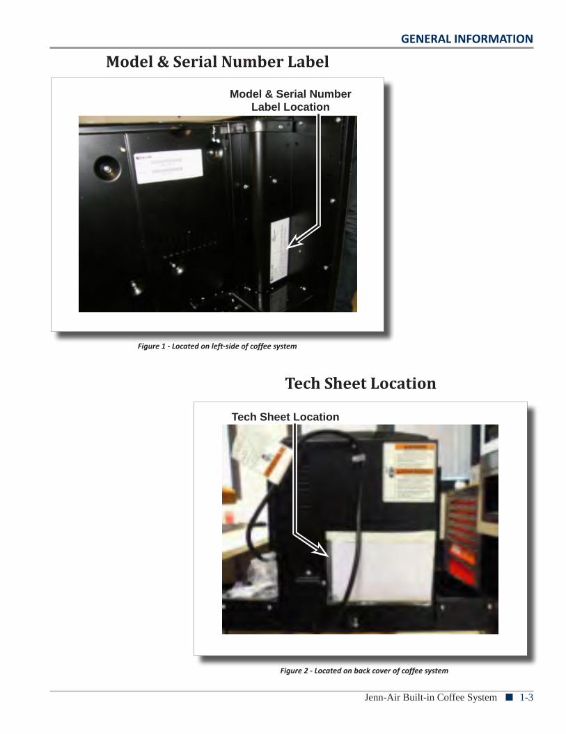
Jenn-Air Built-in Coffee System n 1-3
Model & Serial Number Label Location
Figure 1 - Located on left-side of coffee system
Model & Serial Number Label
Tech Sheet Location
Tech Sheet Location
Figure 2 - Located on back cover of coffee system
1-4 n Jenn-Air Built-in Coffee System
GENERAL INFORMATION
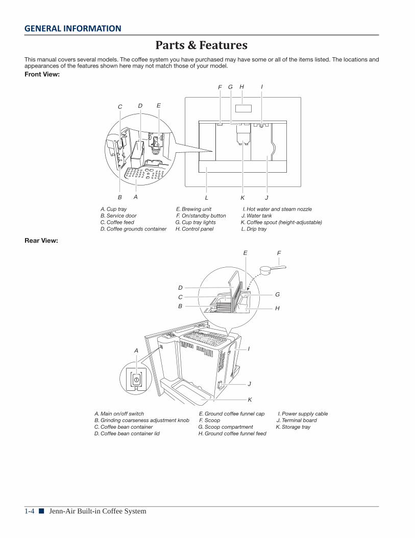
Parts & Features
4
PARTS AND FEATURESThis manual covers several models. The coffee system you have purchased may have some or all of the items listed. The locations and appearances of the features shown here may not match those of your model.
Front View:
Rear View:
A. Cup trayB. Service doorC. Coffee feedD. Coffee grounds container
E. Brewing unitF. On/standby buttonG. Cup tray lightsH. Control panel
I. Hot water and steam nozzleJ. Water tankK. Coffee spout (height-adjustable)L. Drip tray
A. Main on/off switchB. Grinding coarseness adjustment knobC. Coffee bean containerD. Coffee bean container lid
E. Ground coffee funnel capF. ScoopG. Scoop compartmentH. Ground coffee funnel feed
I. Power supply cableJ. Terminal boardK. Storage tray
AB
C D E
G H I
JK
F
L
I
J
K
A
B
C
D
E
G
H
F
GENERAL INFORMATION
Jenn-Air Built-in Coffee System n 1-5
Product Specifications
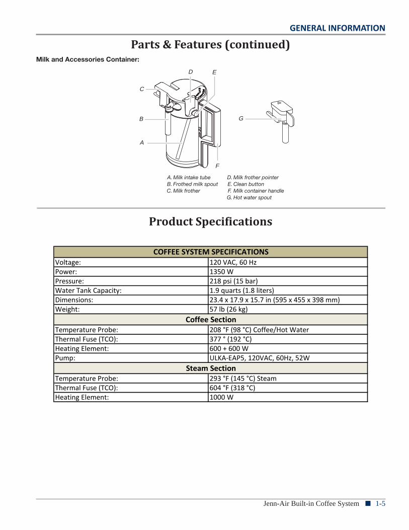
Parts & Features (continued)
Voltage: 120 VAC, 60 Hz Power: 1350 WPressure: 218 psi (15 bar)Water Tank Capacity: 1.9 quarts (1.8 liters)Dimensions: 23.4 x 17.9 x 15.7 in (595 x 455 x 398 mm)Weight: 57 lb (26 kg)
Temperature Probe: 208 °F (98 °C) Coffee/Hot WaterThermal Fuse (TCO): 377 ° (192 °C)Heating Element: 600 + 600 WPump: ULKA-EAP5, 120VAC, 60Hz, 52W
Temperature Probe: 293 °F (145 °C) SteamThermal Fuse (TCO): 604 °F (318 °C)Heating Element: 1000 W
COFFEE SYSTEM SPECIFICATIONS
Coffee Section
Steam Section
5
Milk and Accessories Container:
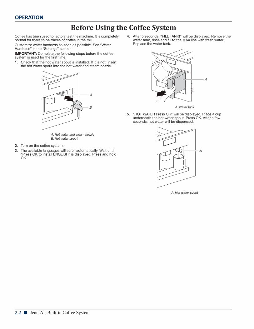
BEFORE USING THE COFFEE SYSTEMCoffee has been used to factory test the machine. It is completely normal for there to be traces of coffee in the mill.Customize water hardness as soon as possible. See “Water Hardness” in the “Settings” section.IMPORTANT: Complete the following steps before the coffee system is used for the first time.1. Check that the hot water spout is installed. If it is not, insert
the hot water spout into the hot water and steam nozzle.
2. Turn on the coffee system.3. The available languages will scroll automatically. Wait until
“Press OK to install ENGLISH” is displayed. Press and hold OK.
4. After 5 seconds, “FILL TANK!” will be displayed. Remove the water tank, rinse and fill to the MAX line with fresh water. Replace the water tank.
5. “HOT WATER Press OK” will be displayed. Place a cup underneath the hot water spout. Press OK. After a few seconds, hot water will be dispensed.
A. Milk intake tubeB. Frothed milk spoutC. Milk frother
D. Milk frother pointerE. Clean buttonF. Milk container handleG. Hot water spout
A
B
C
D E
G
F
A. Hot water and steam nozzleB. Hot water spout
A
B A. Water tank
A. Hot water spout
A
A
1-6 n Jenn-Air Built-in Coffee System
GENERAL INFORMATION
Notes
OPERATION
Jenn-Air Built-in Coffee System n 2-1
Section 2:Operation
This section provides operational use and care information for the “Jenn-Air Built-in Coffee System.”
Q Before Using the Coffee System
Q Coffee System Use
Q Settings
Q Switching On and Preheating
Q Making Coffee or Espresso Using Coffee Beans
Q Changing the Amount of Coffee
Q Adjusting the Coffee Grinder
Q Making Espresso with Ground Coffee
Q Making Cappuccino
Q Dispensing Hot Water
Q Coffee System Care
Q General Cleaning
Q Vacation or Storage
Q Switching Off the Coffee System
Q Consumer Troubleshooting
Q Notes
2-2 n Jenn-Air Built-in Coffee System
OPERATION
Before Using the Coffee System
5
Milk and Accessories Container:
BEFORE USING THE COFFEE SYSTEMCoffee has been used to factory test the machine. It is completely normal for there to be traces of coffee in the mill.Customize water hardness as soon as possible. See “Water Hardness” in the “Settings” section.IMPORTANT: Complete the following steps before the coffee system is used for the first time.1. Check that the hot water spout is installed. If it is not, insert
the hot water spout into the hot water and steam nozzle.
2. Turn on the coffee system.3. The available languages will scroll automatically. Wait until
“Press OK to install ENGLISH” is displayed. Press and hold OK.
4. After 5 seconds, “FILL TANK!” will be displayed. Remove the water tank, rinse and fill to the MAX line with fresh water. Replace the water tank.
5. “HOT WATER Press OK” will be displayed. Place a cup underneath the hot water spout. Press OK. After a few seconds, hot water will be dispensed.
A. Milk intake tubeB. Frothed milk spoutC. Milk frother
D. Milk frother pointerE. Clean buttonF. Milk container handleG. Hot water spout
A
B
C
D E
G
F
A. Hot water and steam nozzleB. Hot water spout
A
B A. Water tank
A. Hot water spout
A
A
OPERATION
Jenn-Air Built-in Coffee System n 2-3
Before Using the Coffee System (continued)
6
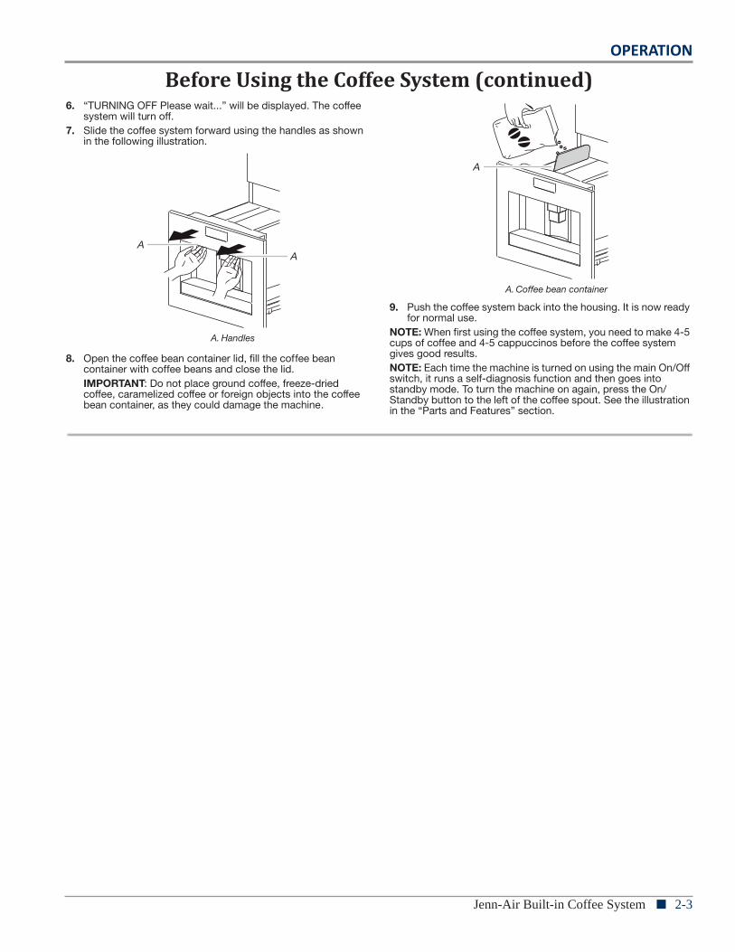
6. “TURNING OFF Please wait...” will be displayed. The coffee system will turn off.
7. Slide the coffee system forward using the handles as shown in the following illustration.
8. Open the coffee bean container lid, fill the coffee bean container with coffee beans and close the lid.IMPORTANT: Do not place ground coffee, freeze-dried coffee, caramelized coffee or foreign objects into the coffee bean container, as they could damage the machine.
9. Push the coffee system back into the housing. It is now ready for normal use.
NOTE: When first using the coffee system, you need to make 4-5 cups of coffee and 4-5 cappuccinos before the coffee system gives good results.NOTE: Each time the machine is turned on using the main On/Off switch, it runs a self-diagnosis function and then goes into standby mode. To turn the machine on again, press the On/Standby button to the left of the coffee spout. See the illustration in the “Parts and Features” section.
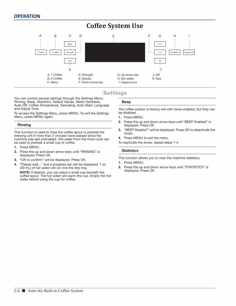
COFFEE SYSTEM USE
SettingsYou can control several settings through the Settings Menu: Rinsing, Beep, Statistics, Default Values, Water Hardness,Auto-Off, Coffee Temperature, Descaling, Auto-Start, Language and Adjust Time.To access the Settings Menu, press MENU. To exit the Settings Menu, press MENU again.
Rinsing
This function is used to rinse the coffee spout or preheat the brewing unit if more than 2 minutes have passed since the machine was last preheated. Hot water from the rinse cycle can be used to preheat a small cup of coffee. 1. Press MENU.2. Press the up and down arrow keys until “RINSING” is
displayed. Press OK.3. “OK to confirm” will be displayed. Press OK.4. “Please wait...” and a progress bar will be displayed. 1 oz
(30 mL) of hot water will run into the drip tray. NOTE: If desired, you can place a small cup beneath the coffee spout. The hot water will warm the cup. Empty the hot water before using the cup for coffee.
Beep
The coffee system is factory-set with tones enabled, but they can be disabled.1. Press MENU.2. Press the up and down arrow keys until “BEEP Enabled” is
displayed. Press OK.3. “BEEP Disable?” will be displayed. Press OK to deactivate the
tones.4. Press MENU to exit the menu.To reactivate the tones, repeat steps 1-4.
Statistics
This function allows you to view the machine statistics.1. Press MENU.2. Press the up and down arrow keys until “STATISTICS” is
displayed. Press OK.
A. Handles
AA
A. Coffee bean container
A
A. 1 CoffeeB. 2 CoffeeC. Menu
D. StrengthE. DisplayF. Down arrow key
G. Up arrow keyH. Hot waterI. Cappuccino
J. OKK. Size
A B C D E G H I
JK
F
2-4 n Jenn-Air Built-in Coffee System
OPERATION
Coffee System Use
6
6. “TURNING OFF Please wait...” will be displayed. The coffee system will turn off.
7. Slide the coffee system forward using the handles as shown in the following illustration.
8. Open the coffee bean container lid, fill the coffee bean container with coffee beans and close the lid.IMPORTANT: Do not place ground coffee, freeze-dried coffee, caramelized coffee or foreign objects into the coffee bean container, as they could damage the machine.
9. Push the coffee system back into the housing. It is now ready for normal use.
NOTE: When first using the coffee system, you need to make 4-5 cups of coffee and 4-5 cappuccinos before the coffee system gives good results.NOTE: Each time the machine is turned on using the main On/Off switch, it runs a self-diagnosis function and then goes into standby mode. To turn the machine on again, press the On/Standby button to the left of the coffee spout. See the illustration in the “Parts and Features” section.
COFFEE SYSTEM USE
SettingsYou can control several settings through the Settings Menu: Rinsing, Beep, Statistics, Default Values, Water Hardness,Auto-Off, Coffee Temperature, Descaling, Auto-Start, Language and Adjust Time.To access the Settings Menu, press MENU. To exit the Settings Menu, press MENU again.
Rinsing
This function is used to rinse the coffee spout or preheat the brewing unit if more than 2 minutes have passed since the machine was last preheated. Hot water from the rinse cycle can be used to preheat a small cup of coffee. 1. Press MENU.2. Press the up and down arrow keys until “RINSING” is
displayed. Press OK.3. “OK to confirm” will be displayed. Press OK.4. “Please wait...” and a progress bar will be displayed. 1 oz
(30 mL) of hot water will run into the drip tray. NOTE: If desired, you can place a small cup beneath the coffee spout. The hot water will warm the cup. Empty the hot water before using the cup for coffee.
Beep
The coffee system is factory-set with tones enabled, but they can be disabled.1. Press MENU.2. Press the up and down arrow keys until “BEEP Enabled” is
displayed. Press OK.3. “BEEP Disable?” will be displayed. Press OK to deactivate the
tones.4. Press MENU to exit the menu.To reactivate the tones, repeat steps 1-4.
Statistics
This function allows you to view the machine statistics.1. Press MENU.2. Press the up and down arrow keys until “STATISTICS” is
displayed. Press OK.
A. Handles
AA
A. Coffee bean container
A
A. 1 CoffeeB. 2 CoffeeC. Menu
D. StrengthE. DisplayF. Down arrow key
G. Up arrow keyH. Hot waterI. Cappuccino
J. OKK. Size
A B C D E G H I
JK
F
OPERATION
Jenn-Air Built-in Coffee System n 2-57
3. Press the up and down arrow keys to see:� Total cups of coffee made
� Total liters of water used
� Total number of descalings
� Total cups of cappuccinos made
4. Press MENU once to exit the Statistics menu. Press MENU again to exit the main menu.
Default Values
This function will restore all settings to the factory-set defaults.1. Press MENU.2. Press the up and down arrow keys until “DEFAULT VALUES”
is displayed. Press OK.3. “OK to confirm” will be displayed. Press OK.4. “Restore” will be displayed for a few seconds. All settings will
be reset to default.5. Press MENU to exit the menu.
Water Hardness
It is important to set the correct water hardness for proper descaling.1. Remove the “Total hardness test” water hardness strip (found
in the bag containing literature) from its packaging.2. Immerse the strip fully in a cup of water for a few seconds.3. Remove the strip and wait approximately 30 seconds until it
changes color and red squares appear on the strip.4. Press MENU.5. Press the up and down arrow keys until “WATER
HARDNESS” is displayed. Press OK.6. Press the up and down arrow keys to select the number of
dots corresponding to the number of red squares that have formed on the test strip. For example, if the test strip shows 3 red squares, select .
7. Press OK.
Auto-Off
The coffee system is factory-set to go into standby mode automatically after 30 minutes of inactivity.1. Press MENU.2. Press the up and down arrow keys until “AUTO-OFF” is
displayed. Press OK.3. Press the up and down arrow keys until the desired period of
time before the coffee system goes into standby mode is selected: 30 minutes, 1 hour or 2 hours.
4. Press OK.5. Press MENU to exit the menu.
Coffee Temperature
The temperature of the brewed coffee can be changed.1. Press MENU.2. Press the up and down arrow keys until “COFFEE
TEMPERATURE” is displayed. Press OK.3. Press the up and down arrow keys until the desired coffee
temperature is selected: low, medium or high.4. Press OK to confirm the temperature chosen.5. Press MENU to exit the menu
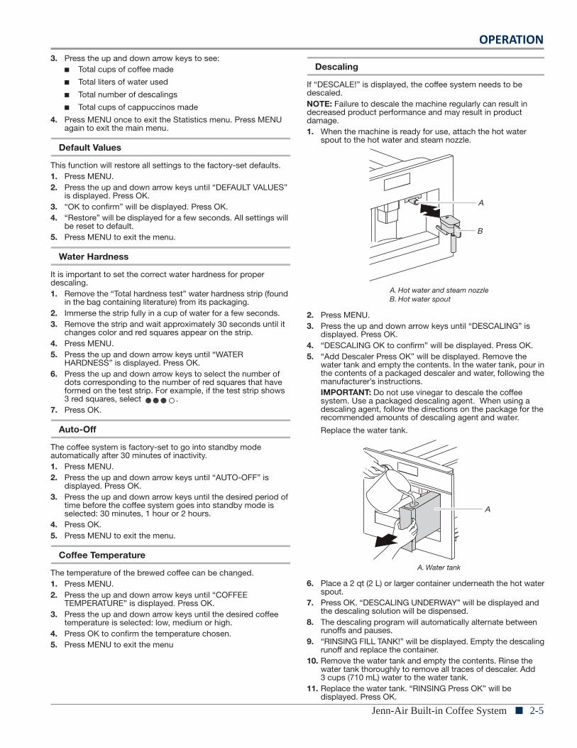
Descaling
If “DESCALE!” is displayed, the coffee system needs to be descaled.NOTE: Failure to descale the machine regularly can result in decreased product performance and may result in product damage.1. When the machine is ready for use, attach the hot water
spout to the hot water and steam nozzle.
2. Press MENU.3. Press the up and down arrow keys until “DESCALING” is
displayed. Press OK.4. “DESCALING OK to confirm” will be displayed. Press OK.5. “Add Descaler Press OK” will be displayed. Remove the
water tank and empty the contents. In the water tank, pour in the contents of a packaged descaler and water, following the manufacturer’s instructions.IMPORTANT: Do not use vinegar to descale the coffee system. Use a packaged descaling agent. When using a descaling agent, follow the directions on the package for the recommended amounts of descaling agent and water.
Replace the water tank.
6. Place a 2 qt (2 L) or larger container underneath the hot water spout.
7. Press OK. “DESCALING UNDERWAY” will be displayed and the descaling solution will be dispensed.
8. The descaling program will automatically alternate between runoffs and pauses.
9. “RINSING FILL TANK!” will be displayed. Empty the descaling runoff and replace the container.
10. Remove the water tank and empty the contents. Rinse the water tank thoroughly to remove all traces of descaler. Add 3 cups (710 mL) water to the water tank.
11. Replace the water tank. “RINSING Press OK” will be displayed. Press OK.
A. Hot water and steam nozzleB. Hot water spout
A. Water tank
A
B
A
2-6 n Jenn-Air Built-in Coffee System
OPERATION
8
12. “RINSING” will be displayed. Hot water will be dispensed.13. “RINSING COMPLETE Press OK” will be displayed. Press OK.14. “FILL TANK!” will be displayed. Remove the water tank, fill it
with clean water and replace the tank.The descaling program is complete, and the machine is ready to prepare coffee.
NOTE: If the descaling cycle is interrupted before it has been completed, it will need to be restarted from the beginning.
Auto Start
The coffee system can be set to switch on automatically at a preset time.NOTE: The internal clock must be set before activating Auto Start. See “Setting the Clock” in this section.To Activate Auto Start:1. Press MENU.2. Press the up and down arrow keys until “AUTO-START
Disabled” is displayed. Press OK.3. “AUTO-START Enable?” will be displayed. Press OK.4. “AUTO-START 07:30” will be displayed. Press the up and
down arrow keys until the desired hour is displayed. Press OK.5. Press the up and down arrow keys until the desired minute is
displayed. Press OK.6. Press OK. The display will show “AUTO-START Enabled.”7. Press MENU to exit the menu.To Change Auto Start while Enabled:1. Press MENU.2. Press the up and down arrow keys until “AUTO-START
Enabled” is displayed. Press OK.3. Press the up and down arrow keys until “ADJUST TIME” is
displayed. Press OK.4. “AUTO-START XX:XX” will be displayed. Press the up and
down arrow keys until the desired hour is displayed. Press OK.5. Press the up and down arrow keys until the desired minute is
displayed. Press OK.6. Press OK. The display will show “AUTO-START Enabled.”7. Press MENU to exit the menu.To Deactivate Auto Start:1. Press MENU.2. Press the up and down arrow keys until “AUTO-START
Enabled” is displayed. Press OK.3. “AUTO-START Disable?” will be displayed. Press OK. The
display will show “AUTO-START Disabled.”4. Press MENU to exit the menu.
Language
The coffee system language can be changed.1. Press MENU.2. Press the up and down arrow keys until “LANGUAGE” is
displayed. Press OK.3. Press the up and down arrow keys until the correct language
is displayed.4. Press OK.5. Press MENU to exit the menu.
Setting the Clock
The coffee system has an internal 24-hour clock.1. Press MENU.2. Press the up and down arrow keys until “ADJUST TIME” is
displayed. Press OK.3. Press the up and down arrow keys until the correct hour is
displayed. Press OK.4. Press the up and down arrow keys until the correct minute is
displayed. Press OK.5. Press MENU to exit the menu.
Switching On and PreheatingEvery time the coffee system is switched on, it will perform an automatic preheat and rinse cycle that cannot be interrupted. The coffee system is ready for use after this cycle is complete.To switch the coffee system on, press the On/Standby button once. “HEATING UP Please wait...” will be displayed. There may be some hot water runoff through the coffee spout.When “MEDIUM CUP Standard taste” is displayed, the coffee system is ready for use.To preheat the coffee system again, see “Rinsing” in the “Settings” section.
Making Coffee or Espresso Using Coffee Beans
The coffee system is factory-set to make a standard-strength medium cup of coffee. The strength of the coffee can be changed by pressing Strength until the desired strength is displayed: extra-mild, mild, standard, strong, extra-strong or ground.NOTE: Do not use ground coffee unless the ground coffee option is selected.To change the amount of coffee dispensed for each cup size, see the “Changing the Amount of Coffee” section.If the display shows “FILL TANK!” the water tank must be filled. The water tank may still contain some water; this is normal.
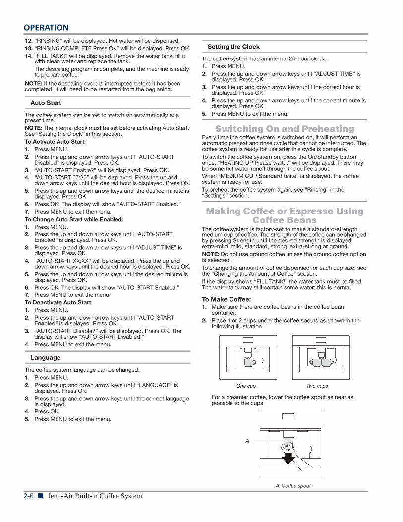
To Make Coffee:1. Make sure there are coffee beans in the coffee bean
container.2. Place 1 or 2 cups under the coffee spouts as shown in the
following illustration.
For a creamier coffee, lower the coffee spout as near as possible to the cups.
One cup Two cups
A. Coffee spout
A
OPERATION
Jenn-Air Built-in Coffee System n 2-79
3. Press SIZE to select the size of the coffee cup: espresso, small cup, medium cup, large cup or mug.
4. Press 1 COFFEE to make 1 cup of coffee or 2 COFFEE to make 2 cups of coffee.
5. The coffee system will grind the coffee beans and dispense the coffee. After the preset quantity of coffee has been dispensed, the coffee system will automatically stop and empty the coffee grounds into the grounds container.NOTE: The coffee system can be interrupted at any time by pressing the 1 Coffee or 2 Coffee button again.
6. After a few seconds, the coffee system will be ready for use again.
7. To switch off the coffee system, press the On/Standby button. The coffee system will run an automatic rinse cycle and then go into standby mode.
If the coffee runoff is too slow or incomplete, or if the runoff is too quick and the coffee is not creamy enough, see the “Adjusting the Coffee Grinder” section.Do not remove the water tank during the coffee runoff. If the water tank is removed, the coffee system cannot make coffee and will display “FILL TANK!” Check the water level in the tank and replace it. To restart the coffee system, press OK. “HOT WATER Press OK” will be displayed. Press OK. Water will run off from the spout for approximately 30 seconds. After the runoff completes, the coffee system will return to the programmed standard settings.The coffee system may require you to repeat the operation several times to eliminate any air in the water line.Tips for Hotter Coffee:� Run a Rinse cycle before brewing coffee. See “Rinsing” in the
“Settings” section.
� Do not use very thick cups as they will absorb the heat unless preheated.
� Preheat all cups by rinsing them with hot water. See “Rinsing” in the “Settings” section.
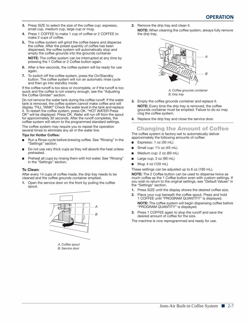
To Clean:After every 14 cups of coffee made, the drip tray needs to be cleaned and the coffee grounds container emptied.1. Open the service door on the front by pulling the coffee
spout.
2. Remove the drip tray and clean it.NOTE: When cleaning the coffee system, always fully remove the drip tray.
3. Empty the coffee grounds container and replace it.NOTE: Every time the drip tray is removed, the coffee grounds container must be emptied. Failure to do so may clog the coffee system.
4. Replace the drip tray and close the service door.
Changing the Amount of CoffeeThe coffee system is factory-set to automatically deliver approximately the following amounts of coffee:� Espresso: 1 oz (30 mL)
� Small cup: 1½ oz (45 mL)
� Medium cup: 2 oz (60 mL)
� Large cup: 3 oz (90 mL)
� Mug: 4 oz (120 mL)
These settings can be adjusted up to 6 oz (180 mL).NOTE: The 2 Coffee button can be used to dispense twice as much coffee as the 1 Coffee button even with custom settings. If you wish to return to the original settings, see “Default Values” in the “Settings” section.1. Press SIZE until the display shows the desired coffee size.2. Place your cup beneath the coffee spout. Press and hold
1 COFFEE until “PROGRAM QUANTITY” is displayed.NOTE: The coffee system will begin dispensing coffee before “PROGRAM QUANTITY” is displayed.
3. Press 1 COFFEE again to stop the runoff and save the desired amount of coffee for the size.
The machine is now reprogrammed and ready for use.
A. Coffee spoutB. Service door
A
B
A. Coffee grounds containerB. Drip tray
A
B
2-8 n Jenn-Air Built-in Coffee System
OPERATION
10
Adjusting the Coffee GrinderThe coffee grinder is factory-set and does not require adjustment. If coffee runoff is too fast or too slow, the grinding coarseness can be adjusted.NOTE: The grinding coarseness adjustment knob can be turned only while the grinder is in operation.
For slower runoff and creamier coffee, turn the knob 1 click counterclockwise (finer ground coffee).For faster runoff, turn the knob 1 click clockwise (coarser ground coffee).
Making Espresso with Ground Coffee
1. Press STRENGTH repeatedly until “Ground” is selected.2. Slide the coffee system forward using the handles as shown
in the following illustration.
3. Lift the small central lid, pour one scoop of ground coffee into the funnel.NOTE: Only use ground coffee meant for espresso coffee machines.
NOTE: Use only the scoop provided. Do not add more than one scoop of ground coffee.
4. Close the central lid. Push the coffee system back into the housing and continue with Step 2 in the “Making Coffee or Espresso Using Coffee Beans” section.NOTE: Only one cup of coffee can be made at a time with ground coffee. Do not use 2 COFFEE.
To deactivate the ground coffee function, press STRENGTH again.
Making Cappuccino1. Press STRENGTH until the desired strength is selected.2. Twist the milk container lid clockwise and lift up to remove it.
3. Fill the container with approximately ½ cup (100 mL) of milk for each cappuccino you want to make. Do not fill above the MAX line on the milk container. For best results, use cold skim or 2% milk.
A. Grinding coarseness adjustment knob
A. Counterclockwise for finer grindB. Clockwise for coarser grind
A. Handles
A
A
B
AA
A. Center funnel
A
1
2
OPERATION
Jenn-Air Built-in Coffee System n 2-9
11
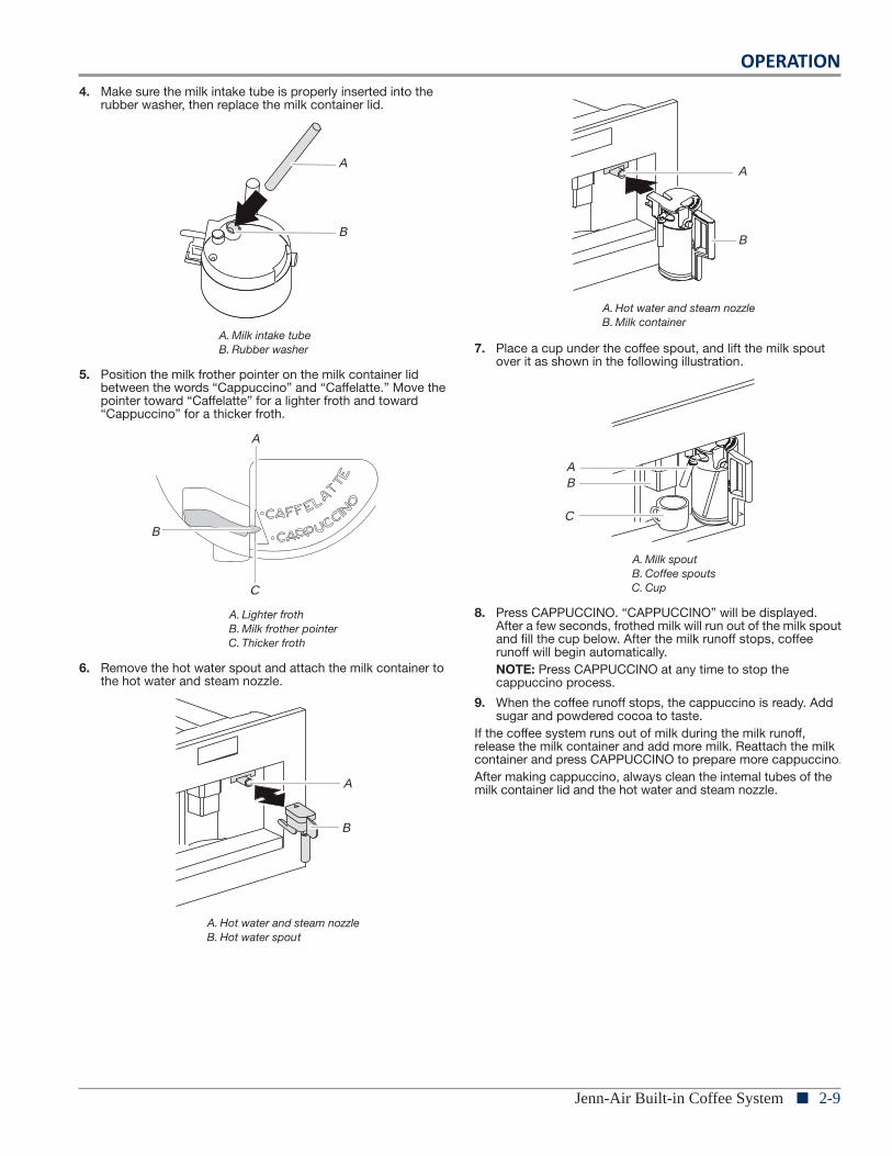
4. Make sure the milk intake tube is properly inserted into the rubber washer, then replace the milk container lid.
5. Position the milk frother pointer on the milk container lid between the words “Cappuccino” and “Caffelatte.” Move the pointer toward “Caffelatte” for a lighter froth and toward “Cappuccino” for a thicker froth.
6. Remove the hot water spout and attach the milk container to the hot water and steam nozzle.
7. Place a cup under the coffee spout, and lift the milk spout over it as shown in the following illustration.
8. Press CAPPUCCINO. “CAPPUCCINO” will be displayed. After a few seconds, frothed milk will run out of the milk spout and fill the cup below. After the milk runoff stops, coffee runoff will begin automatically.NOTE: Press CAPPUCCINO at any time to stop the cappuccino process.
9. When the coffee runoff stops, the cappuccino is ready. Add sugar and powdered cocoa to taste.
If the coffee system runs out of milk during the milk runoff, release the milk container and add more milk. Reattach the milk container and press CAPPUCCINO to prepare more cappuccino.After making cappuccino, always clean the internal tubes of the milk container lid and the hot water and steam nozzle.
A. Milk intake tubeB. Rubber washer
A. Lighter frothB. Milk frother pointerC. Thicker froth
A. Hot water and steam nozzleB. Hot water spout
A
B
B
A
C
A
B
A. Hot water and steam nozzleB. Milk container
A. Milk spoutB. Coffee spoutsC. Cup
A
B
AB
C
2-10 n Jenn-Air Built-in Coffee System
OPERATION
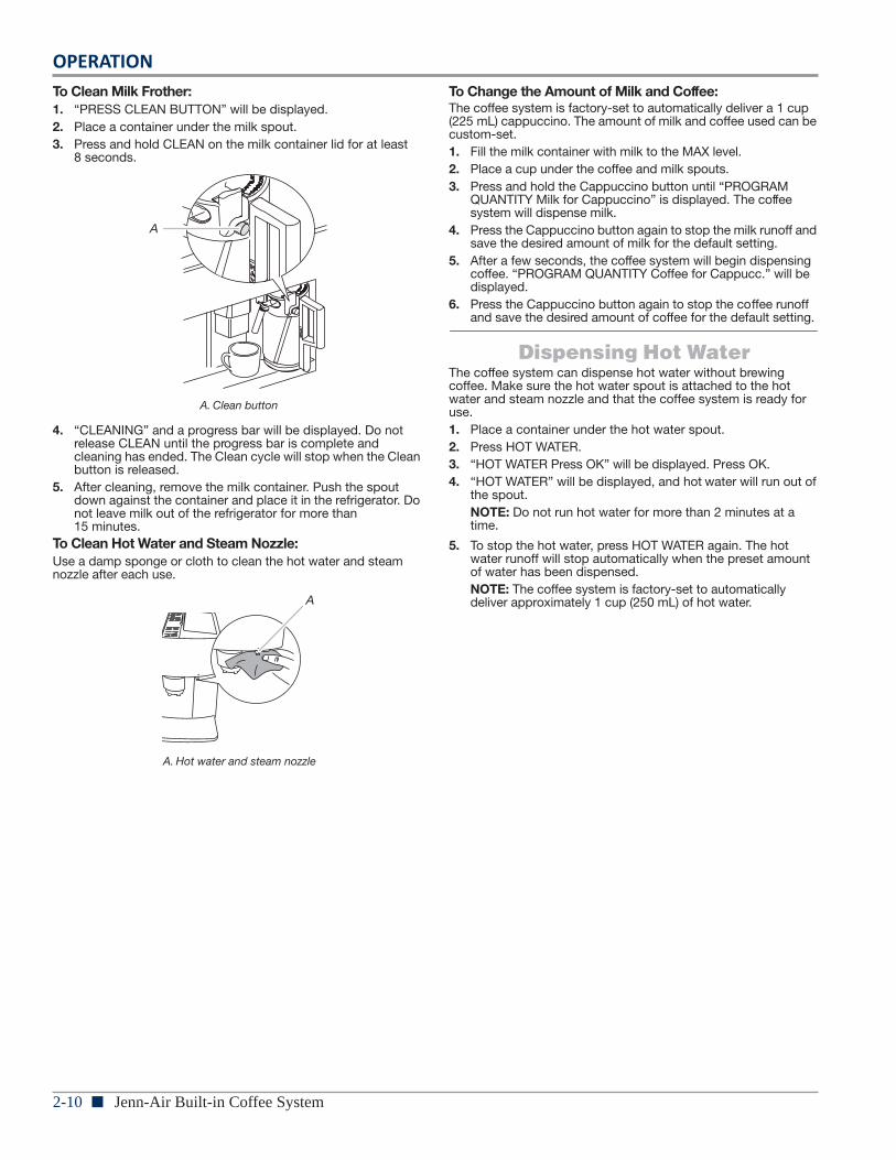
12
To Clean Milk Frother:1. “PRESS CLEAN BUTTON” will be displayed.2. Place a container under the milk spout.3. Press and hold CLEAN on the milk container lid for at least
8 seconds.
4. “CLEANING” and a progress bar will be displayed. Do not release CLEAN until the progress bar is complete and cleaning has ended. The Clean cycle will stop when the Clean button is released.
5. After cleaning, remove the milk container. Push the spout down against the container and place it in the refrigerator. Do not leave milk out of the refrigerator for more than 15 minutes.
To Clean Hot Water and Steam Nozzle:Use a damp sponge or cloth to clean the hot water and steam nozzle after each use.
To Change the Amount of Milk and Coffee:The coffee system is factory-set to automatically deliver a 1 cup (225 mL) cappuccino. The amount of milk and coffee used can be custom-set.1. Fill the milk container with milk to the MAX level.2. Place a cup under the coffee and milk spouts.3. Press and hold the Cappuccino button until “PROGRAM
QUANTITY Milk for Cappuccino” is displayed. The coffee system will dispense milk.
4. Press the Cappuccino button again to stop the milk runoff and save the desired amount of milk for the default setting.
5. After a few seconds, the coffee system will begin dispensing coffee. “PROGRAM QUANTITY Coffee for Cappucc.” will be displayed.
6. Press the Cappuccino button again to stop the coffee runoff and save the desired amount of coffee for the default setting.
Dispensing Hot WaterThe coffee system can dispense hot water without brewing coffee. Make sure the hot water spout is attached to the hot water and steam nozzle and that the coffee system is ready for use.1. Place a container under the hot water spout.2. Press HOT WATER.3. “HOT WATER Press OK” will be displayed. Press OK.4. “HOT WATER” will be displayed, and hot water will run out of
the spout.NOTE: Do not run hot water for more than 2 minutes at a time.
5. To stop the hot water, press HOT WATER again. The hot water runoff will stop automatically when the preset amount of water has been dispensed.NOTE: The coffee system is factory-set to automatically deliver approximately 1 cup (250 mL) of hot water.
A. Clean button
A. Hot water and steam nozzle
A
A
OPERATION
Jenn-Air Built-in Coffee System n 2-11
Coffee System Care
13
COFFEE SYSTEM CARE
General CleaningTo avoid damage to the coffee system, do not use solvents or abrasive detergents to clean the coffee system. Use a soft damp cloth to clean the exterior of the coffee system. Clean all machine parts regularly.IMPORTANT: Before any cleaning, turn the coffee system off using the main On/Off switch and unplug it.IMPORTANT: Do not immerse the coffee system in water.
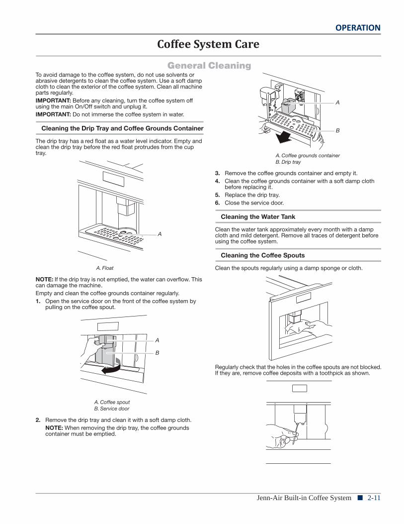
Cleaning the Drip Tray and Coffee Grounds Container
The drip tray has a red float as a water level indicator. Empty and clean the drip tray before the red float protrudes from the cup tray.
NOTE: If the drip tray is not emptied, the water can overflow. This can damage the machine.Empty and clean the coffee grounds container regularly.1. Open the service door on the front of the coffee system by
pulling on the coffee spout.
2. Remove the drip tray and clean it with a soft damp cloth.NOTE: When removing the drip tray, the coffee grounds container must be emptied.
3. Remove the coffee grounds container and empty it.4. Clean the coffee grounds container with a soft damp cloth
before replacing it.5. Replace the drip tray.6. Close the service door.
Cleaning the Water Tank
Clean the water tank approximately every month with a damp cloth and mild detergent. Remove all traces of detergent before using the coffee system.
Cleaning the Coffee Spouts
Clean the spouts regularly using a damp sponge or cloth.
Regularly check that the holes in the coffee spouts are not blocked. If they are, remove coffee deposits with a toothpick as shown.
A. Float
A. Coffee spoutB. Service door
A
A
B
A. Coffee grounds containerB. Drip tray
A
B
2-12 n Jenn-Air Built-in Coffee System
OPERATION
14
Cleaning the Ground Coffee Feed Funnel
Check approximately once a month that the feed funnel for ground coffee is not blocked.
Cleaning the Inside
Check the inside of the coffee system approximately once a week for dirt and debris. If necessary, remove coffee deposits with a damp sponge or cloth.
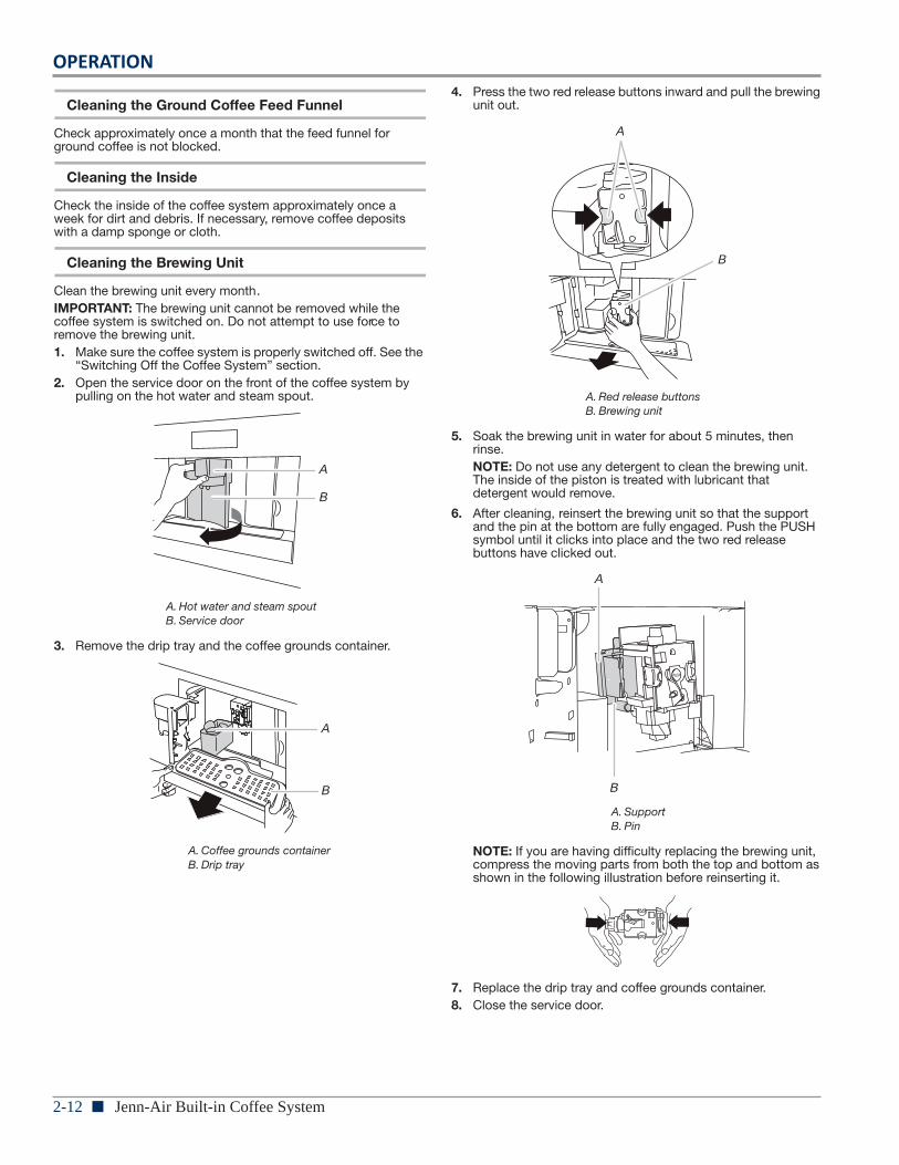
Cleaning the Brewing Unit
Clean the brewing unit every month.IMPORTANT: The brewing unit cannot be removed while the coffee system is switched on. Do not attempt to use force to remove the brewing unit.1. Make sure the coffee system is properly switched off. See the
“Switching Off the Coffee System” section.2. Open the service door on the front of the coffee system by
pulling on the hot water and steam spout.
3. Remove the drip tray and the coffee grounds container.
4. Press the two red release buttons inward and pull the brewing unit out.
5. Soak the brewing unit in water for about 5 minutes, then rinse.NOTE: Do not use any detergent to clean the brewing unit. The inside of the piston is treated with lubricant that detergent would remove.
6. After cleaning, reinsert the brewing unit so that the support and the pin at the bottom are fully engaged. Push the PUSH symbol until it clicks into place and the two red release buttons have clicked out.
NOTE: If you are having difficulty replacing the brewing unit, compress the moving parts from both the top and bottom as shown in the following illustration before reinserting it.
7. Replace the drip tray and coffee grounds container.8. Close the service door.
A. Hot water and steam spoutB. Service door
A. Coffee grounds containerB. Drip tray
A
B
A
B
A. Red release buttonsB. Brewing unit
A. SupportB. Pin
A
B
A
B
OPERATION
Jenn-Air Built-in Coffee System n 2-13
15
Cleaning the Milk Container
All of the milk container components can be washed in the top rack of a dishwasher.1. Turn the milk container lid clockwise and remove it.2. Remove the milk spout and intake tube.3. Remove the pointer by pulling it outward.4. Wash all the components thoroughly with hot water and mild
detergent. Make sure there is no milk residue left inside the holes or the groove on the fine end of the pointer.
5. Check that the intake tube and spout are not clogged with milk residue.
6. Replace the pointer, milk spout, and intake tube.7. Replace the milk container lid.
Vacation or StorageIf the coffee system will be unused for an extended period of time, empty the coffee grounds container, drip tray and water tank. Turn the coffee system off using the main On/Off switch and unplug it before storage.
Switching Off the Coffee SystemEach time the coffee system is put into standby mode, it performs an automatic rinse that cannot be interrupted.To turn off the coffee system, press the On/Standby button on the front of the coffee system. “TURNING OFF Please wait...” will display, and hot water will run off from the coffee spout.The coffee system will automatically go into standby mode after 30 minutes. To change this duration, see “Auto-Off” in the “Settings” section.NOTE: If the coffee system will not be used for an extended period of time, press the main On/Off button on the side of the machine. Auto-Set will not work when the machine is turned off by the main On/Off button.
2-14 n Jenn-Air Built-in Coffee System
OPERATION
Consumer Troubleshooting
16
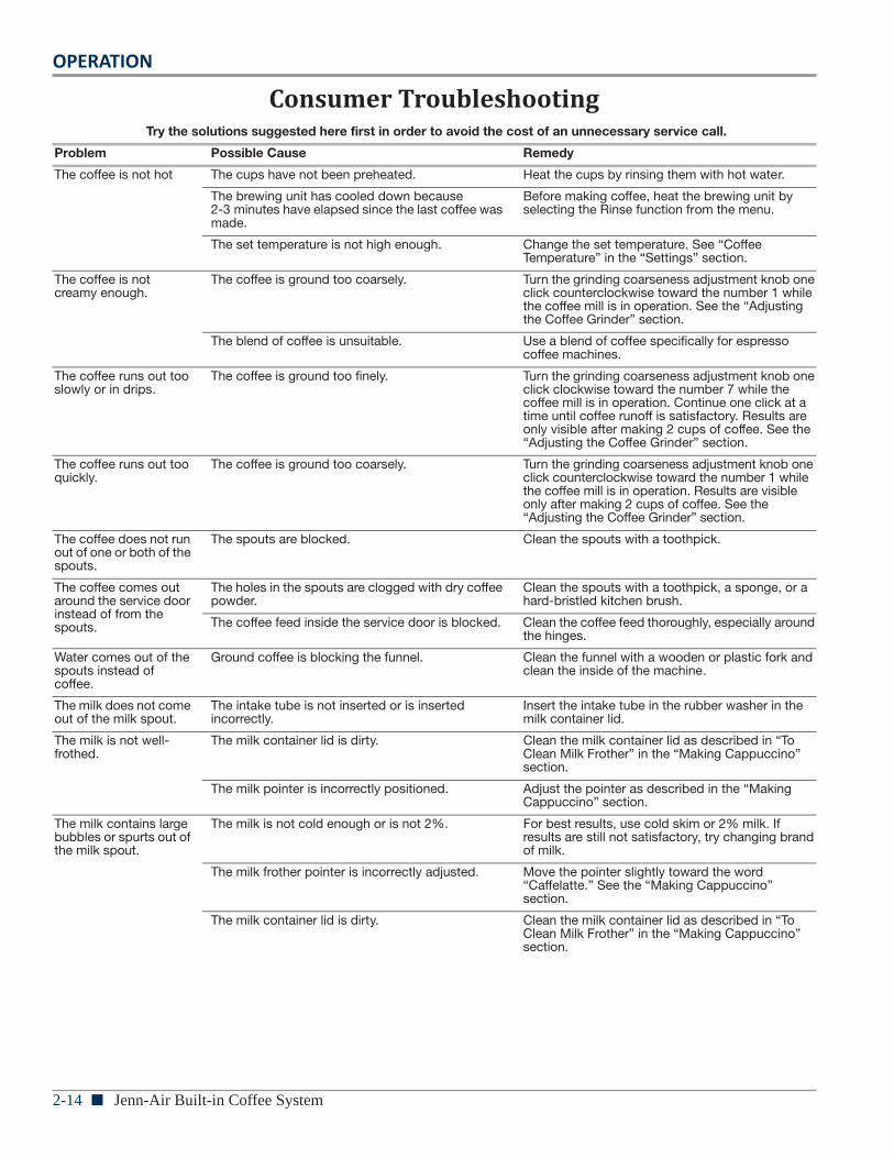
TROUBLESHOOTINGTry the solutions suggested here first in order to avoid the cost of an unnecessary service call.
Problem Possible Cause Remedy
The coffee is not hot The cups have not been preheated. Heat the cups by rinsing them with hot water.
The brewing unit has cooled down because 2-3 minutes have elapsed since the last coffee was made.
Before making coffee, heat the brewing unit by selecting the Rinse function from the menu.
The set temperature is not high enough. Change the set temperature. See “Coffee Temperature” in the “Settings” section.
The coffee is not creamy enough.
The coffee is ground too coarsely. Turn the grinding coarseness adjustment knob one click counterclockwise toward the number 1 while the coffee mill is in operation. See the “Adjusting the Coffee Grinder” section.
The blend of coffee is unsuitable. Use a blend of coffee specifically for espresso coffee machines.
The coffee runs out too slowly or in drips.
The coffee is ground too finely. Turn the grinding coarseness adjustment knob one click clockwise toward the number 7 while the coffee mill is in operation. Continue one click at a time until coffee runoff is satisfactory. Results are only visible after making 2 cups of coffee. See the “Adjusting the Coffee Grinder” section.
The coffee runs out too quickly.
The coffee is ground too coarsely. Turn the grinding coarseness adjustment knob one click counterclockwise toward the number 1 while the coffee mill is in operation. Results are visible only after making 2 cups of coffee. See the “Adjusting the Coffee Grinder” section.
The coffee does not run out of one or both of the spouts.
The spouts are blocked. Clean the spouts with a toothpick.
The coffee comes out around the service door instead of from the spouts.
The holes in the spouts are clogged with dry coffee powder.
Clean the spouts with a toothpick, a sponge, or a hard-bristled kitchen brush.
The coffee feed inside the service door is blocked. Clean the coffee feed thoroughly, especially around the hinges.
Water comes out of the spouts instead of coffee.
Ground coffee is blocking the funnel. Clean the funnel with a wooden or plastic fork and clean the inside of the machine.
The milk does not come out of the milk spout.
The intake tube is not inserted or is inserted incorrectly.
Insert the intake tube in the rubber washer in the milk container lid.
The milk is not well-frothed.
The milk container lid is dirty. Clean the milk container lid as described in “To Clean Milk Frother” in the “Making Cappuccino” section.
The milk pointer is incorrectly positioned. Adjust the pointer as described in the “Making Cappuccino” section.
The milk contains large bubbles or spurts out of the milk spout.
The milk is not cold enough or is not 2%. For best results, use cold skim or 2% milk. If results are still not satisfactory, try changing brand of milk.
The milk frother pointer is incorrectly adjusted. Move the pointer slightly toward the word “Caffelatte.” See the “Making Cappuccino” section.
The milk container lid is dirty. Clean the milk container lid as described in “To Clean Milk Frother” in the “Making Cappuccino” section.
OPERATION
Jenn-Air Built-in Coffee System n 2-15
17
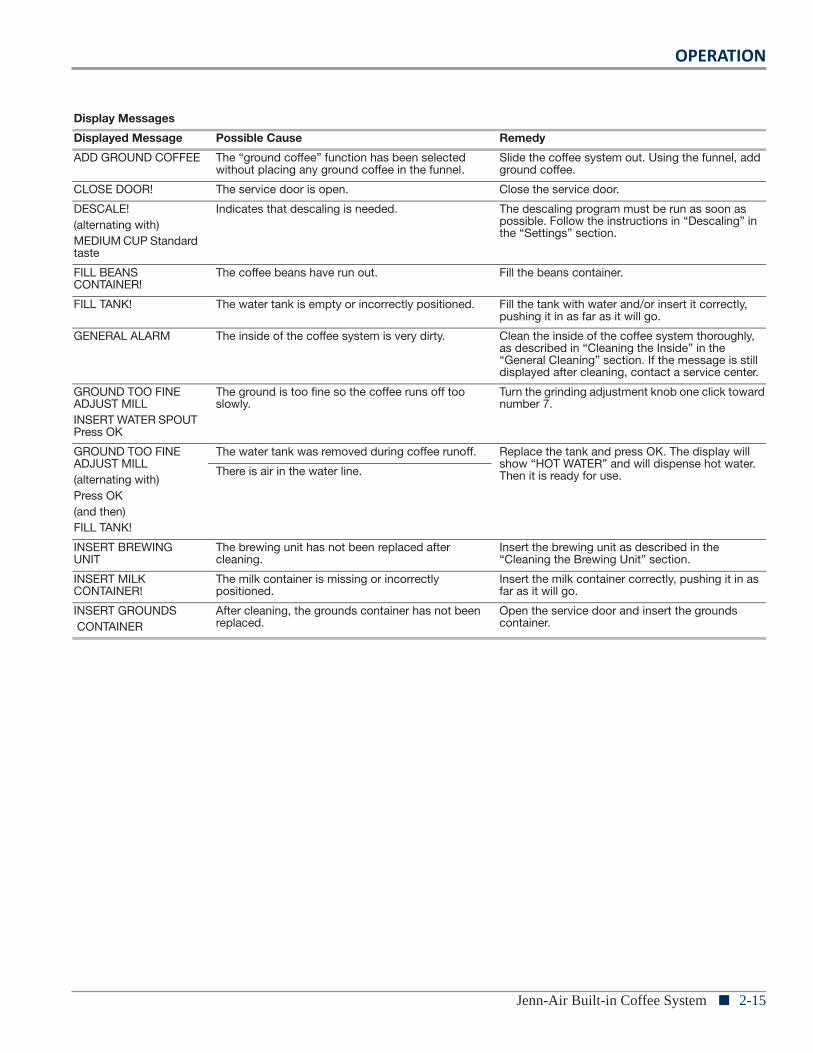
Display Messages
Displayed Message Possible Cause Remedy
ADD GROUND COFFEE The “ground coffee” function has been selected without placing any ground coffee in the funnel.
Slide the coffee system out. Using the funnel, add ground coffee.
CLOSE DOOR! The service door is open. Close the service door.
DESCALE!(alternating with)MEDIUM CUP Standard taste
Indicates that descaling is needed. The descaling program must be run as soon as possible. Follow the instructions in “Descaling” in the “Settings” section.
FILL BEANS CONTAINER!
The coffee beans have run out. Fill the beans container.
FILL TANK! The water tank is empty or incorrectly positioned. Fill the tank with water and/or insert it correctly, pushing it in as far as it will go.
GENERAL ALARM The inside of the coffee system is very dirty. Clean the inside of the coffee system thoroughly, as described in “Cleaning the Inside” in the “General Cleaning” section. If the message is still displayed after cleaning, contact a service center.
GROUND TOO FINE ADJUST MILLINSERT WATER SPOUT Press OK
The ground is too fine so the coffee runs off too slowly.
Turn the grinding adjustment knob one click toward number 7.
GROUND TOO FINE ADJUST MILL(alternating with)Press OK(and then)FILL TANK!
The water tank was removed during coffee runoff. Replace the tank and press OK. The display will show “HOT WATER” and will dispense hot water. Then it is ready for use.There is air in the water line.
INSERT BREWING UNIT
The brewing unit has not been replaced after cleaning.
Insert the brewing unit as described in the “Cleaning the Brewing Unit” section.
INSERT MILK CONTAINER!
The milk container is missing or incorrectly positioned.
Insert the milk container correctly, pushing it in as far as it will go.
INSERT GROUNDS CONTAINER
After cleaning, the grounds container has not been replaced.
Open the service door and insert the grounds container.
2-16 n Jenn-Air Built-in Coffee System
OPERATION
Notes
INSTALLATION
Jenn-Air Built-in Coffee System n 3-1
Section 3:Installation
This section provides installation requirements and procedures for the “Jenn-Air Built-in Coffee System.”
n Installation Requirements
n Tools and Parts
n Location Requirements
n Electrical Requirements
n Installation Instructions
n Install Mounting Brackets
n Install Coffee System
n Complete Installation
n Notes
3-2 n Jenn-Air Built-in Coffee System
INSTALLATION
Installation Requirements
2
INSTALLATION REQUIREMENTS
Tools and PartsTools NeededGather the required tools and parts before starting installation. Read and follow the instructions provided with any tools listed here.
Parts SuppliedAll of the following parts are provided, but some parts may not be used. The location of your coffee system installation will determine which parts you will use.
Location RequirementsIMPORTANT: Observe all governing codes and ordinances. � Cabinet opening dimensions that are shown must be used.
Given dimensions provide minimum clearance with coffee system.
� The built-in coffee system must be installed in cabinetry with the dimensions provided.
� Follow the installation instructions for any cabinetry used to house the built-in coffee system. Make sure cabinet is securely attached to the wall.
� Follow the installation instructions
� Recessed installation area must provide complete enclosure around the recessed portion of the coffee system.
� Grounded electrical supply is required. See “Electrical Requirements” section.
� Refer to installation instructions for cutout dimensions for any appliances installed above or below the built-in coffee system.
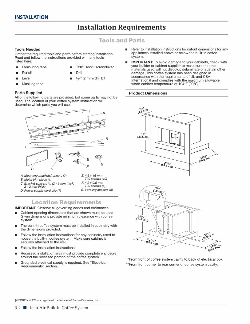
� IMPORTANT: To avoid damage to your cabinets, check with your builder or cabinet supplier to make sure that the materials used will not discolor, delaminate or sustain other damage. This coffee system has been designed in accordance with the requirements of UL and CSA International and complies with the maximum allowable wood cabinet temperature of 194°F (90°C).
Product Dimensions
*From front of coffee system cavity to back of electrical box.**From front corner to rear corner of coffee system cavity.
� Measuring tape
� Pencil
� Level
� Masking tape
� T20®† Torx®† screwdriver
� Drill
� ⁵⁄₆₄" (2 mm) drill bit
A. Mounting brackets/runners (2)B. Metal trim piece (1)C. Bracket spacers (4) (2 - 1 mm thick;
2 - 2 mm thick)D. Power supply cord clip (1)
E. 4.5 x 16 mm T20 screws (19)
F. 4.2 x 9.5 mm T20 screws (4)
G. Leveling spacers (8)
†®TORX and T20 are registered trademarks of Saturn Fasteners, Inc.
A
B
C D
E
FG 23³⁄₈"(59.5 cm)
18"(45.5 cm)
15⁵⁄₈"
(39.8 cm)
¹³⁄₁₆"
(2.1 cm)
20¹¹⁄₁₆"(52.8 cm)14³⁄₈"
(36.1 cm)**
14⁹⁄₁₆"(37.2 cm)
¹¹⁄₁₆"(1.9 cm)
15¹⁄₄"
(38.0 cm)*
INSTALLATION
Jenn-Air Built-in Coffee System n 3-33
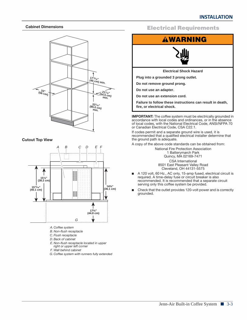
Cabinet Dimensions
Cutout Top View
Electrical Requirements
IMPORTANT: The coffee system must be electrically grounded in accordance with local codes and ordinances, or in the absence of local codes, with the National Electrical Code, ANSI/NFPA 70 or Canadian Electrical Code, CSA C22.1.If codes permit and a separate ground wire is used, it is recommended that a qualified electrical installer determine that the ground path is adequate.A copy of the above code standards can be obtained from:
National Fire Protection Association1 Batterymarch Park
Quincy, MA 02169-7471CSA International
8501 East Pleasant Valley RoadCleveland, OH 44131-5575
� A 120 volt, 60 Hz., AC only, 15-amp fused, electrical circuit is required. A time-delay fuse or circuit breaker is also recommended. It is recommended that a separate circuit serving only this coffee system be provided.
� Check that the outlet provides 120-volt power and is correctly grounded.
A. Coffee systemB. Non-flush receptacleC. Flush receptacleD. Back of cabinetE. Non-flush receptacle located in upper
right or upper left cornerF. Wall behind cabinetG. Coffee system with runners fully extended
22"(56 cm)21⁷⁄₁₆" (54.5 cm) min.
17¹³⁄₁₆" (45 cm) min.
33⁷⁄₁₆" (85.0 cm) min.
G
A B C ED F
15¹⁄₈"(38.2 cm)
14³⁄₈"(36.1 cm)
17⁵⁄₈"(44.8 cm)
15¹⁵⁄₁₆"(40.1 cm)
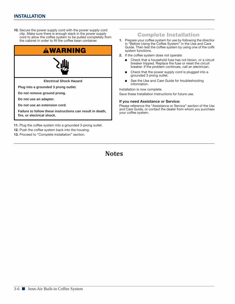
Electrical Shock Hazard
Plug into a grounded 3 prong outlet.
Do not remove ground prong.
Do not use an adapter.
Do not use an extension cord.
Failure to follow these instructions can result in death, fire, or electrical shock.
WARNING
Electrical Shock Hazard
Plug into a grounded 3 prong outlet.
Do not remove ground prong.
Do not use an adapter.
Do not use an extension cord.
Failure to follow these instructions can result in death, fire, or electrical shock.
WARNING
3-4 n Jenn-Air Built-in Coffee System
INSTALLATION
Installation Instructions
4
INSTALLATION INSTRUCTIONS
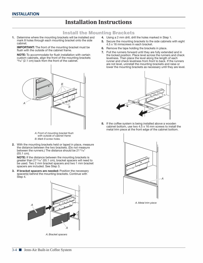
Install the Mounting Brackets1. Determine where the mounting brackets will be installed and
mark 8 holes through each mounting bracket onto the side cabinet. IMPORTANT: The front of the mounting bracket must be flush with the outside of the cabinet frame.
NOTE: To accommodate for flush installation with certain custom cabinets, align the front of the mounting brackets ¹³⁄₁₆" (2.1 cm) back from the front of the cabinet.
2. With the mounting brackets held or taped in place, measure the distance between the two brackets. (Do not measure between the runners.) The distance should be 21¹¹⁄₁₆" (55.1 cm).NOTE: If the distance between the mounting brackets is greater than 21¹¹⁄₁₆" (55.1 cm), bracket spacers will need to be used. Two 2 mm bracket spacers and two 1 mm bracket spacers are included. See Step 3.
3. If bracket spacers are needed: Position the necessary spacer(s) behind the mounting brackets. Continue with Step 4.
4. Using a 2 mm drill, drill the holes marked in Step 1.5. Secure the mounting brackets to the side cabinets with eight
4.5 x 16 mmscrews in each bracket.6. Remove the tape holding the brackets in place.7. Pull the runners forward until they are fully extended and in
the locked position. Place level across the runners and check levelness. Then place the level along the length of each runner and check levelness from front to back. If the runners are not level, uninstall the mounting brackets and raise or lower the mounting brackets as necessary until they are level.
8. If the coffee system is being installed above a wooden cabinet bottom, use two 4.5 x 16 mm screws to install the metal trim piece at the front edge of the cabinet bottom.
A. Front of mounting bracket flush with outside of cabinet frame
B. Mark 8 screw holes.
A. Bracket spacers
AB
B
A
A
A. Metal trim piece
A
INSTALLATION
Jenn-Air Built-in Coffee System n 3-55
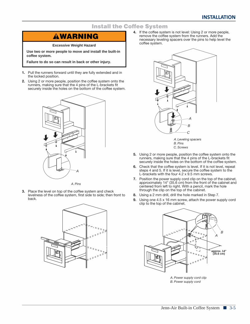
Install the Coffee System
1. Pull the runners forward until they are fully extended and in the locked position.
2. Using 2 or more people, position the coffee system onto the runners, making sure that the 4 pins of the L-brackets fit securely inside the holes on the bottom of the coffee system.
3. Place the level on top of the coffee system and check levelness of the coffee system, first side to side; then front to back.
4. If the coffee system is not level: Using 2 or more people, remove the coffee system from the runners. Add the necessary leveling spacers over the pins to help level the coffee system.
5. Using 2 or more people, position the coffee system onto the runners, making sure that the 4 pins of the L-brackets fit securely inside the holes on the bottom of the coffee system.
6. Check that the coffee system is level. If it is not level, repeat steps 4 and 5. If it is level, secure the coffee system to the L-brackets with the four 4.2 x 9.5 mm screws.
7. Position the power supply cord clip on the top of the cabinet, approximately 14" (35.6 cm) from the front of the cabinet and centered from left to right. With a pencil, mark the hole through the clip on the top of the cabinet.
8. Using a 2 mm drill, drill the hole marked in Step 7.9. Using one 4.5 x 16 mm screw, attach the power supply cord
clip to the top of the cabinet.
A. Pins
WARNINGExcessive Weight Hazard
Use two or more people to move and install the built-in coffee system.
Failure to do so can result in back or other injury.
A
A. Leveling spacersB. PinsC. Screws
A. Power supply cord clipB. Power supply cord
B
C
A
approx. 14"(35.6 cm)
AB
Electrical Shock Hazard
Plug into a grounded 3 prong outlet.
Do not remove ground prong.
Do not use an adapter.
Do not use an extension cord.
Failure to follow these instructions can result in death, fire, or electrical shock.
WARNING
3-6 n Jenn-Air Built-in Coffee System
INSTALLATION
6
10. Secure the power supply cord with the power supply cord clip. Make sure there is enough slack in the power supply cord to allow the coffee system to be pulled completely from the cabinet in order to fill the coffee bean container.
11. Plug the coffee system into a grounded 3-prong outlet.12. Push the coffee system back into the housing.13. Proceed to “Complete Installation” section.
Complete Installation1. Prepare your coffee system for use by following the directions
in “Before Using the Coffee System” in the Use and Care Guide. Then test the coffee system by using one of the coffee system functions.
2. If the coffee system does not operate:� Check that a household fuse has not blown, or a circuit
breaker tripped. Replace the fuse or reset the circuit breaker. If the problem continues, call an electrician.
� Check that the power supply cord is plugged into a grounded 3 prong outlet.
� See the Use and Care Guide for troubleshooting information.
Installation is now complete.Save these Installation Instructions for future use.
If you need Assistance or Service:Please reference the “Assistance or Service” section of the Use and Care Guide, or contact the dealer from whom you purchased your coffee system.
Electrical Shock Hazard
Plug into a grounded 3 prong outlet.
Do not remove ground prong.
Do not use an adapter.
Do not use an extension cord.
Failure to follow these instructions can result in death, fire, or electrical shock.
WARNING
Notes
Electrical Shock Hazard
Plug into a grounded 3 prong outlet.
Do not remove ground prong.
Do not use an adapter.
Do not use an extension cord.
Failure to follow these instructions can result in death, fire, or electrical shock.
WARNING
COMPONENT ACCESS
Jenn-Air Built-in Coffee System n 4-1
Section 4:Component Access
This section provides service parts access, removal, and installation instructions for the “Jenn-Air Built-in Coffee System.”
n Coffee System Exploded Views
n Coffee System Parts List
n Jenn-Air Built-in Coffee System Disassembly Section
n Before Disassembling the Coffee System
n Removing the Fan Panel
n Removing the Back Panel & Trays
n Removing the Main Power Board
n Removing the Flow Meter
n Removing the Water Pump
n Removing the Steam Heater & 3-way Valve
n Removing the Diverter/Transmission Assembly
n Removing the Coffee Heater
n Removing the Display Board & 2-way Valve
n Removing the Grinder Assembly
n Grinder Setup
n Notes
4-2 n Jenn-Air Built-in Coffee System
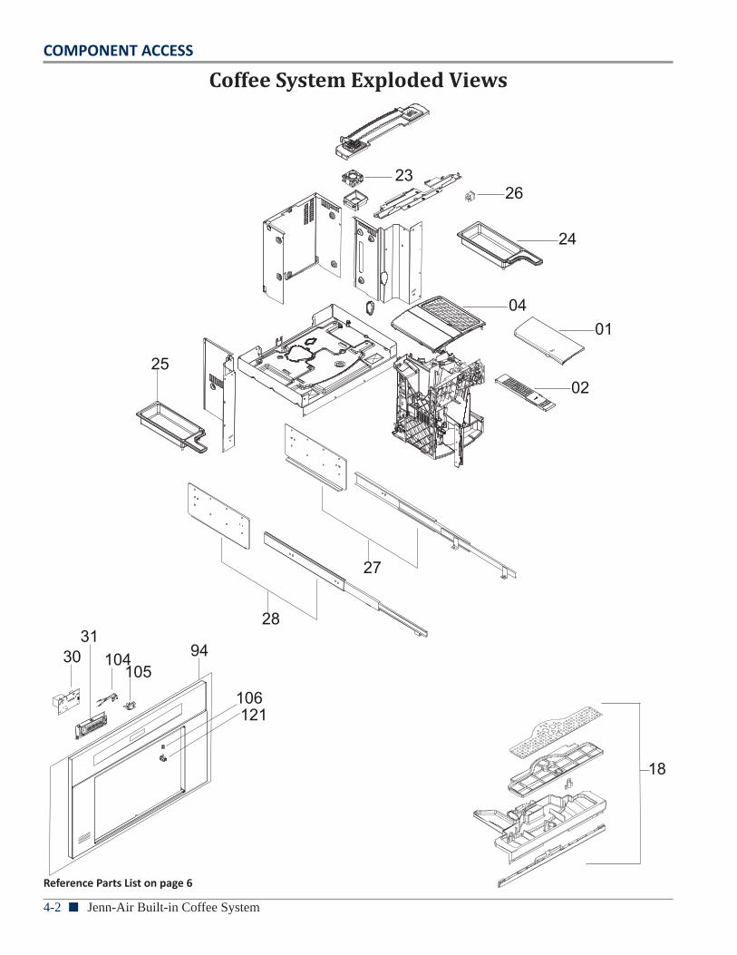
COMPONENT ACCESS
Coffee System Exploded Views
Reference Parts List on page 6
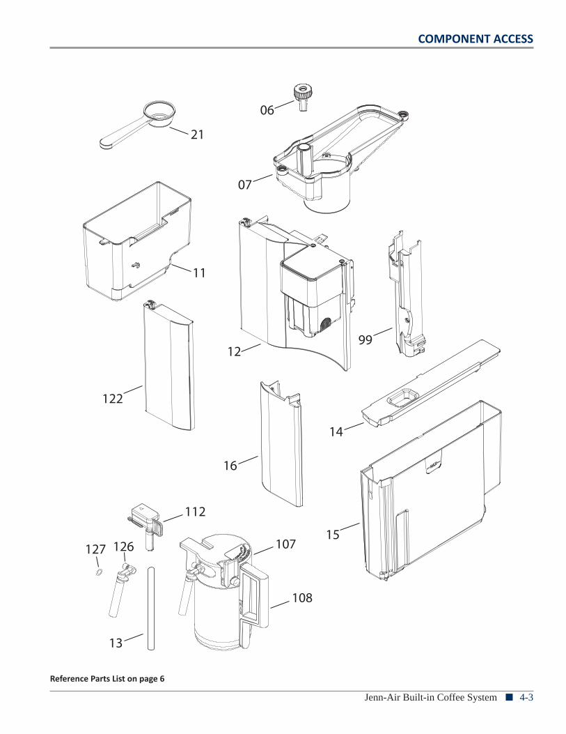
COMPONENT ACCESS
Jenn-Air Built-in Coffee System n 4-3
112
13
126127
122
16
15
14
1299
07
06
11
21
107
108
Reference Parts List on page 6
4-4 n Jenn-Air Built-in Coffee System
COMPONENT ACCESS
55
56
57
51
52
40
4142
43
37
3536
A
A
53
58
4847474950
47
46
39
115
32
33
34
Reference Parts List on page 6
COMPONENT ACCESS
Jenn-Air Built-in Coffee System n 4-5
C
97
95
6868 96
98
103
60
91
6090
9380
80
60
81
92
86
75
78
66
62
64
68
7480
77
A
63
46
82
7960
81
88
846087
85
8488
85
102
60
AB
80
89
90
60
B
C
60
101
100 83
83
67
128
Reference Parts List on page 6
4-6 n Jenn-Air Built-in Coffee System
COMPONENT ACCESS
REF # PART DESCRIPTION REF # PART DESCRIPTION001 COVER 062 PROTECTOR002 COVER 064 PUMP004 CLOSURE 066 SENSOR REED006 KNOB 067 POWER BOARD007 TANK 068 MICROSWITCH011 TRAY 074 HEATING ELEMENT ASSY012 DOOR ASSY 075 TCO013 TUBE 077 TCO014 COVER 078 FLOWMETER015 TRAY 079 TUBE PTFE D12‐DE4, L=135 1BUSHES016 PROFILE 080 GASKET018 PAN ASSY 081 CONNECDTION021 MEASURING SPOON 082 TUBE PTFE D12‐DE4, L=150 2BUSHES023 VENTILATOR 083 CLIP024 TRAY 084 CONNECTOR025 TRAY 085 O‐RING D=4,5026 SWITCH 086 FILTER027 RUNNER RIGHT 087 TUBE PTFE D12‐DE4, L=270 2 BUSHES028 RUNNER LEFT 088 SPRING030 BOARD LED 089 TUBE PTFE D12‐DE4, L=150 2BUSHES031 CONTROL BOARD 090 CONNECTION032 MICROSWITCH 091 SOLENOID VALVE033 COMPLETE GRINDER 092 TUBE PTFE D12‐DE4, L=335 1 BUSHES034 GASKET 093 SOLENOID VALVE035 DIFFUSER 094 FRAME ASSEMBLY036 O‐RING 095 O‐RING037 INFUSION KIT 096 COUPLING CARAFE039 WIRING TCO 097 O‐RING040 SUPPORT 098 O‐RING041 SPRING 099 COVER042 MICROSWITCH 100 CLIP CLAMP043 SLIDER 101 CONNECTION046 SENSOR NTC 102 HOOK047 O‐RING 103 TUBE PTFE D12‐DE4, L=170 2 BUSHES048 PIN 104 SPRING, MICROSWITCH049 VALVE 105 SUPPORT050 SPRING 106 SPRING051 O‐RING 107 COVER ASSEMBLY052 FILTER 108 CARAFE053 GENERATOR 112 PIPETTE055 MICROSWITCH 115 SCREW056 HALL SENSOR 121 BUTTON ON/OFF057 BELT 122 FRONT PIECE058 TRANSMISSION KIT 126 TUBE DISTRIBUTING060 O‐RING D=3,85 127 O‐RING D=6061 VALVE 128 REGULATOR
Coffee System Part List
COMPONENT ACCESS
Jenn-Air Built-in Coffee System n 4-7
Jenn-Air Built-in Coffee System
— Disassembly Section —
4-8 n Jenn-Air Built-in Coffee System
COMPONENT ACCESS
9
3. Press SIZE to select the size of the coffee cup: espresso, small cup, medium cup, large cup or mug.
4. Press 1 COFFEE to make 1 cup of coffee or 2 COFFEE to make 2 cups of coffee.
5. The coffee system will grind the coffee beans and dispense the coffee. After the preset quantity of coffee has been dispensed, the coffee system will automatically stop and empty the coffee grounds into the grounds container.NOTE: The coffee system can be interrupted at any time by pressing the 1 Coffee or 2 Coffee button again.
6. After a few seconds, the coffee system will be ready for use again.
7. To switch off the coffee system, press the On/Standby button. The coffee system will run an automatic rinse cycle and then go into standby mode.
If the coffee runoff is too slow or incomplete, or if the runoff is too quick and the coffee is not creamy enough, see the “Adjusting the Coffee Grinder” section.Do not remove the water tank during the coffee runoff. If the water tank is removed, the coffee system cannot make coffee and will display “FILL TANK!” Check the water level in the tank and replace it. To restart the coffee system, press OK. “HOT WATER Press OK” will be displayed. Press OK. Water will run off from the spout for approximately 30 seconds. After the runoff completes, the coffee system will return to the programmed standard settings.The coffee system may require you to repeat the operation several times to eliminate any air in the water line.Tips for Hotter Coffee:� Run a Rinse cycle before brewing coffee. See “Rinsing” in the
“Settings” section.
� Do not use very thick cups as they will absorb the heat unless preheated.
� Preheat all cups by rinsing them with hot water. See “Rinsing” in the “Settings” section.
To Clean:After every 14 cups of coffee made, the drip tray needs to be cleaned and the coffee grounds container emptied.1. Open the service door on the front by pulling the coffee
spout.
2. Remove the drip tray and clean it.NOTE: When cleaning the coffee system, always fully remove the drip tray.
3. Empty the coffee grounds container and replace it.NOTE: Every time the drip tray is removed, the coffee grounds container must be emptied. Failure to do so may clog the coffee system.
4. Replace the drip tray and close the service door.
Changing the Amount of CoffeeThe coffee system is factory-set to automatically deliver approximately the following amounts of coffee:� Espresso: 1 oz (30 mL)
� Small cup: 1½ oz (45 mL)
� Medium cup: 2 oz (60 mL)
� Large cup: 3 oz (90 mL)
� Mug: 4 oz (120 mL)
These settings can be adjusted up to 6 oz (180 mL).NOTE: The 2 Coffee button can be used to dispense twice as much coffee as the 1 Coffee button even with custom settings. If you wish to return to the original settings, see “Default Values” in the “Settings” section.1. Press SIZE until the display shows the desired coffee size.2. Place your cup beneath the coffee spout. Press and hold
1 COFFEE until “PROGRAM QUANTITY” is displayed.NOTE: The coffee system will begin dispensing coffee before “PROGRAM QUANTITY” is displayed.
3. Press 1 COFFEE again to stop the runoff and save the desired amount of coffee for the size.
The machine is now reprogrammed and ready for use.
A. Coffee spoutB. Service door
A
B
A. Coffee grounds containerB. Drip tray
A
B
Before Disassembling the Coffee System
WARNING
Electrical Shock HazardDisconnect power before servicing.
Failure to do so can result in death orelectrical shock.
Replace all parts and panels before operating.
PreparationPerform the following to prepare coffee system for disassembly.
1. Slide the coffee system forward using the handles as shown in the following illustration.
2. Press main on/off switch (A) on right side of coffee system to turn off unit.
Front View:
Rear View:
A. Cup trayB. Service doorC. Coffee feedD. Coffee grounds container
E. Brewing unitF. On/standby buttonG. Cup tray lightsH. Control panel
I. Hot water and steam nozzleJ. Water tankK. Coffee spout (height-adjustable)L. Drip tray
A. Main on/off switchB. Grinding coarseness adjustment knobC. Coffee bean containerD. Coffee bean container lid
E. Ground coffee funnel capG. Scoop compartmentF. ScoopH. Ground coffee funnel feed
I. Power supply cableJ. Terminal boardK. Storage tray
AB
C D E
G H I
JK
F
L
A
3. Unplug coffee system or disconnect power. 4. Remove power cord from power cord clip in cabinet.5. Remove all items from right and left storage trays (“B”
in previous illustration), e.g., bags of coffee beans, containers of ground coffee, sugar, creamer, etc.
6. If installed, remove hot water spout or milk container. 7. Remove water tank (“B” in following illustration). 8. Open service door (D) and remove drip tray (C) with
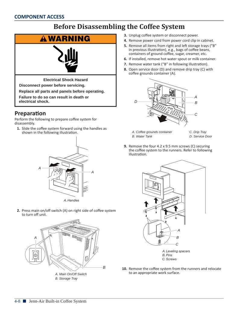
coffee grounds container (A).
9. Remove the four 4.2 x 9.5 mm screws (C) securing the coffee system to the runners. Refer to following illustration.
5
Install the Coffee System
1. Pull the runners forward until they are fully extended and in the locked position.
2. Using 2 or more people, position the coffee system onto the runners, making sure that the 4 pins of the L-brackets fit securely inside the holes on the bottom of the coffee system.
3. Place the level on top of the coffee system and check levelness of the coffee system, first side to side; then front to back.
4. If the coffee system is not level: Using 2 or more people, remove the coffee system from the runners. Add the necessary leveling spacers over the pins to help level the coffee system.
5. Using 2 or more people, position the coffee system onto the runners, making sure that the 4 pins of the L-brackets fit securely inside the holes on the bottom of the coffee system.
6. Check that the coffee system is level. If it is not level, repeat steps 4 and 5. If it is level, secure the coffee system to the L-brackets with the 4 screws.
7. Position the power supply cord clip on the top of the cabinet, approximately 14" (35.6 cm) from the front of the cabinet and centered from left to right. With a pencil, mark the hole through the clip on the top of the cabinet.
8. Using a 2 mm drill, drill the hole marked in Step 7.9. Using 1 screw, attach the power supply cord clip to the top of
the cabinet.
A. Pins
WARNINGExcessive Weight Hazard
Use two or more people to move and install the built-in coffee system.
Failure to do so can result in back or other injury.
A
A. Leveling spacersB. PinsC. Screws
A. Power supply cord clipB. Power supply cord
B
C
A
approx. 14"(35.6 cm)
AB
10. Remove the coffee system from the runners and relocate to an appropriate work surface. A. Main On/Off Switch
B. Storage Tray
A. Coffee grounds container C. Drip TrayB. Water Tank D. Service Door
C
BDA
B
6
6. “TURNING OFF Please wait...” will be displayed. The coffee system will turn off.
7. Slide the coffee system forward using the handles as shown in the following illustration.
8. Open the coffee bean container lid, fill the coffee bean container with coffee beans and close the lid.IMPORTANT: Do not place ground coffee, freeze-dried coffee, caramelized coffee or foreign objects into the coffee bean container, as they could damage the machine.
9. Push the coffee system back into the housing. It is now ready for normal use.
NOTE: When first using the coffee system, you need to make 4-5 cups of coffee and 4-5 cappuccinos before the coffee system gives good results.NOTE: Each time the machine is turned on using the main On/Off switch, it runs a self-diagnosis function and then goes into standby mode. To turn the machine on again, press the On/Standby button to the left of the coffee spout. See the illustration in the “Parts and Features” section.
COFFEE SYSTEM USE
SettingsYou can control several settings through the Settings Menu: Rinsing, Beep, Statistics, Default Values, Water Hardness,Auto-Off, Coffee Temperature, Descaling, Auto-Start, Language and Adjust Time.To access the Settings Menu, press MENU. To exit the Settings Menu, press MENU again.
Rinsing
This function is used to rinse the coffee spout or preheat the brewing unit if more than 2 minutes have passed since the machine was last preheated. Hot water from the rinse cycle can be used to preheat a small cup of coffee. 1. Press MENU.2. Press the up and down arrow keys until “RINSING” is
displayed. Press OK.3. “OK to confirm” will be displayed. Press OK.4. “Please wait...” and a progress bar will be displayed. 1 oz
(30 mL) of hot water will run into the drip tray. NOTE: If desired, you can place a small cup beneath the coffee spout. The hot water will warm the cup. Empty the hot water before using the cup for coffee.
Beep
The coffee system is factory-set with tones enabled, but they can be disabled.1. Press MENU.2. Press the up and down arrow keys until “BEEP Enabled” is
displayed. Press OK.3. “BEEP Disable?” will be displayed. Press OK to deactivate the
tones.4. Press MENU to exit the menu.To reactivate the tones, repeat steps 1-4.
Statistics
This function allows you to view the machine statistics.1. Press MENU.2. Press the up and down arrow keys until “STATISTICS” is
displayed. Press OK.
A. Handles
AA
A. Coffee bean container
A
A. 1 CoffeeB. 2 CoffeeC. Menu
D. StrengthE. DisplayF. Down arrow key
G. Up arrow keyH. Hot waterI. Cappuccino
J. OKK. Size
A B C D E G H I
JK
F
COMPONENT ACCESS
Jenn-Air Built-in Coffee System n 4-9
Removing the Fan Panel
WARNING
Electrical Shock HazardDisconnect power before servicing.
Failure to do so can result in death orelectrical shock.
Replace all parts and panels before operating.
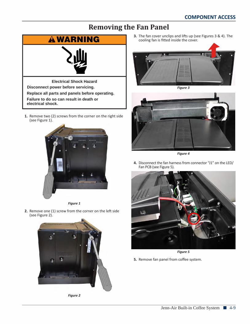
1. Remove two (2) screws from the corner on the right side (see Figure 1).
Figure 1
2. Remove one (1) screw from the corner on the left side (see Figure 2).
Figure 2
3. The fan cover unclips and lifts up (see Figures 3 & 4). The cooling fan is fitted inside the cover.
Figure 3
Figure 4
4. Disconnect the fan harness from connector “J1” on the LED/Fan PCB (see Figure 5).
Figure 5
5. Remove fan panel from coffee system.
4-10 n Jenn-Air Built-in Coffee System
COMPONENT ACCESS
1. First, perform preparation procedure on page 4-8, “Before Disassembling the Coffee System” prior to performing the following steps.
2. Follow the procedures to “Remove Fan Panel” on preceding page.
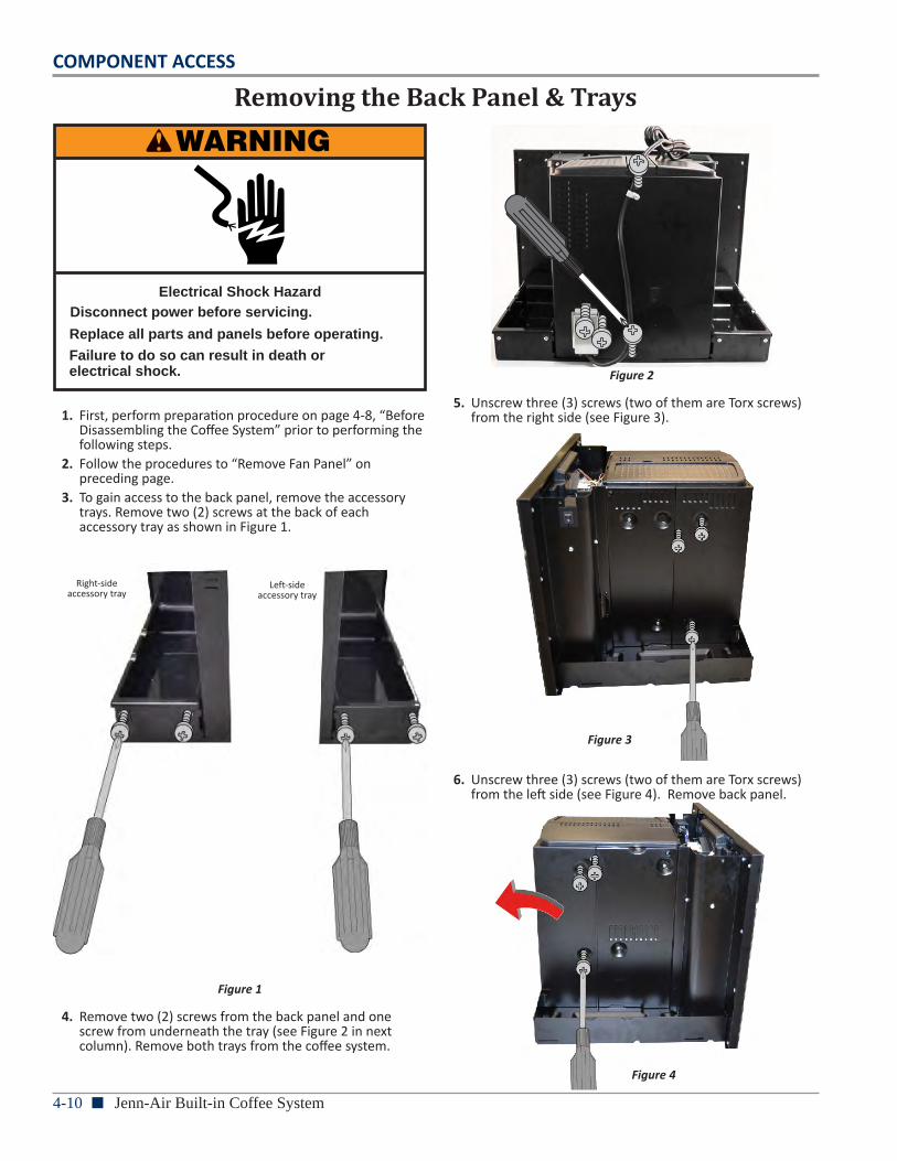
3. To gain access to the back panel, remove the accessory trays. Remove two (2) screws at the back of each accessory tray as shown in Figure 1.
Figure 1
4. Remove two (2) screws from the back panel and one screw from underneath the tray (see Figure 2 in next column). Remove both trays from the coffee system.
Removing the Back Panel & Trays
WARNING
Electrical Shock HazardDisconnect power before servicing.
Failure to do so can result in death orelectrical shock.
Replace all parts and panels before operating.
Figure 2
5. Unscrew three (3) screws (two of them are Torx screws) from the right side (see Figure 3).
6. Unscrew three (3) screws (two of them are Torx screws) from the left side (see Figure 4). Remove back panel.
Right-side accessory tray
Left-side accessory tray
Figure 4
Figure 3
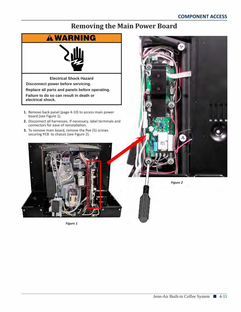
COMPONENT ACCESS
Jenn-Air Built-in Coffee System n 4-11
WARNING
Electrical Shock HazardDisconnect power before servicing.
Failure to do so can result in death orelectrical shock.
Replace all parts and panels before operating.
Removing the Main Power Board
1. Remove back panel (page 4-10) to access main power board (see Figure 1).
2. Disconnect all harnesses. If necessary, label terminals and connectors for ease of reinstallation.
3. To remove main board, remove the five (5) screws securing PCB to chassis (see Figure 2).
Figure 1
Figure 2
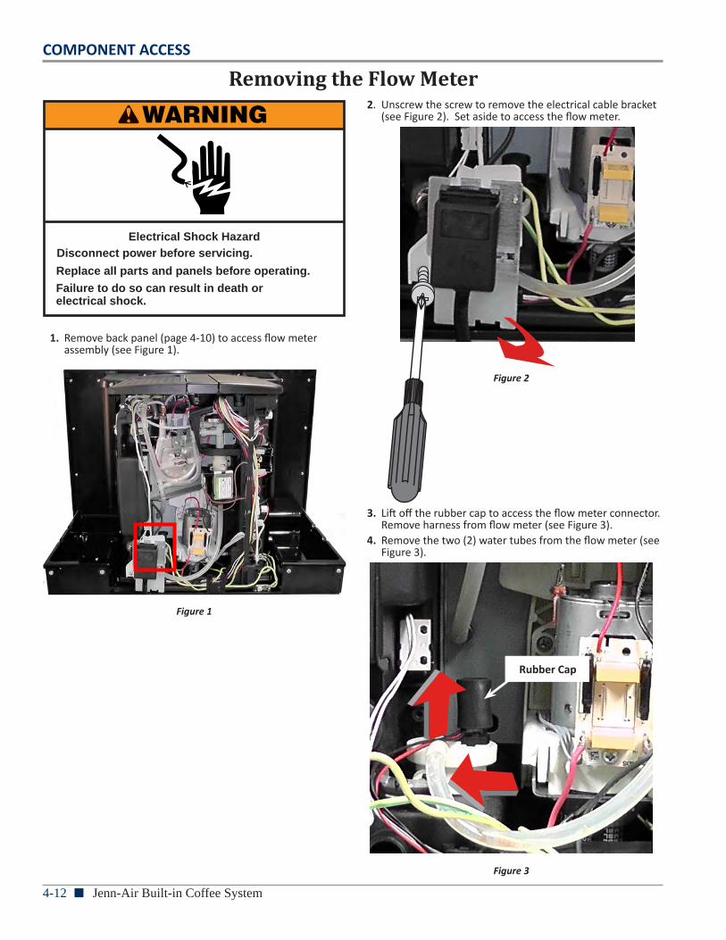
4-12 n Jenn-Air Built-in Coffee System
COMPONENT ACCESS
WARNING
Electrical Shock HazardDisconnect power before servicing.
Failure to do so can result in death orelectrical shock.
Replace all parts and panels before operating.
Removing the Flow Meter
1. Remove back panel (page 4-10) to access flow meter assembly (see Figure 1).
Figure 1
2. Unscrew the screw to remove the electrical cable bracket (see Figure 2). Set aside to access the flow meter.
Figure 2
3. Lift off the rubber cap to access the flow meter connector. Remove harness from flow meter (see Figure 3).
4. Remove the two (2) water tubes from the flow meter (see Figure 3).
Figure 3
Rubber Cap
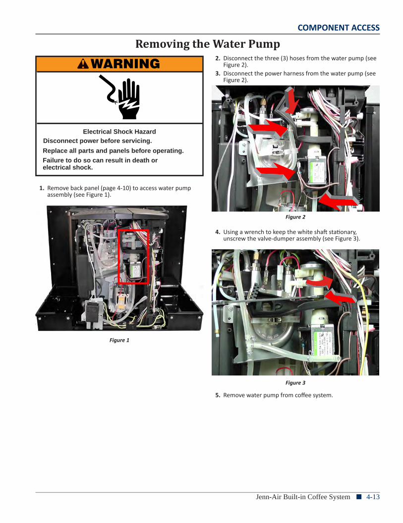
COMPONENT ACCESS
Jenn-Air Built-in Coffee System n 4-13
WARNING
Electrical Shock HazardDisconnect power before servicing.
Failure to do so can result in death orelectrical shock.
Replace all parts and panels before operating.
Removing the Water Pump
1. Remove back panel (page 4-10) to access water pump assembly (see Figure 1).
Figure 1
2. Disconnect the three (3) hoses from the water pump (see Figure 2).
3. Disconnect the power harness from the water pump (see Figure 2).
Figure 2
4. Using a wrench to keep the white shaft stationary, unscrew the valve-dumper assembly (see Figure 3).
Figure 3
5. Remove water pump from coffee system.
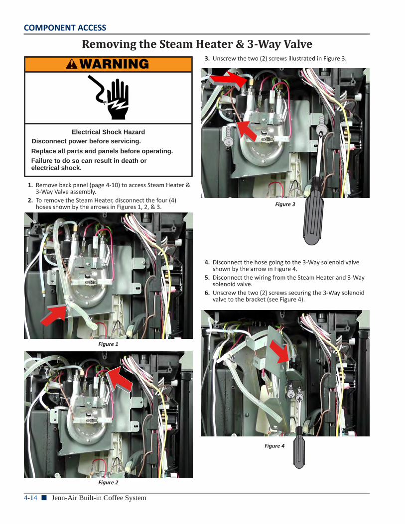
4-14 n Jenn-Air Built-in Coffee System
COMPONENT ACCESS
WARNING
Electrical Shock HazardDisconnect power before servicing.
Failure to do so can result in death orelectrical shock.
Replace all parts and panels before operating.
Removing the Steam Heater & 3-Way Valve
1. Remove back panel (page 4-10) to access Steam Heater & 3-Way Valve assembly.
2. To remove the Steam Heater, disconnect the four (4) hoses shown by the arrows in Figures 1, 2, & 3.
Figure 1
Figure 2
3. Unscrew the two (2) screws illustrated in Figure 3.
Figure 3
4. Disconnect the hose going to the 3-Way solenoid valve shown by the arrow in Figure 4.
5. Disconnect the wiring from the Steam Heater and 3-Way solenoid valve.
6. Unscrew the two (2) screws securing the 3-Way solenoid valve to the bracket (see Figure 4).
Figure 4
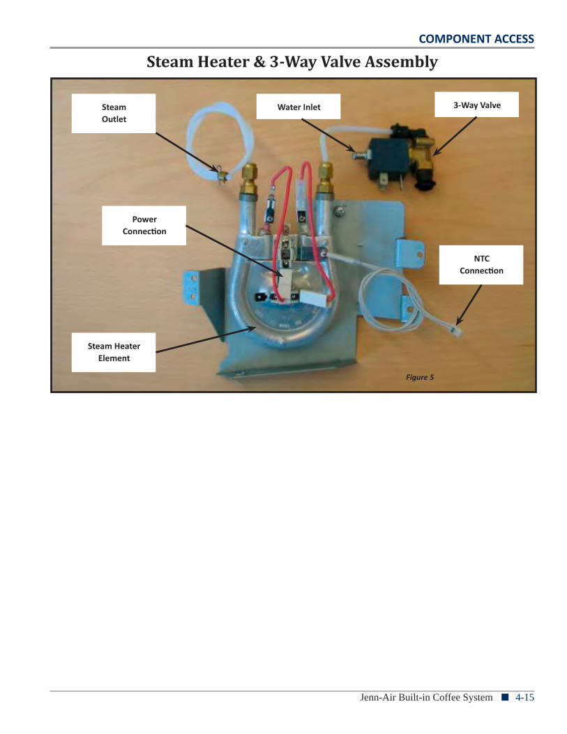
COMPONENT ACCESS
Jenn-Air Built-in Coffee System n 4-15
SteamOutlet
Steam HeaterElement
Power Connection
3-Way Valve
NTC Connection
Water Inlet
Steam Heater & 3-Way Valve Assembly
Figure 5
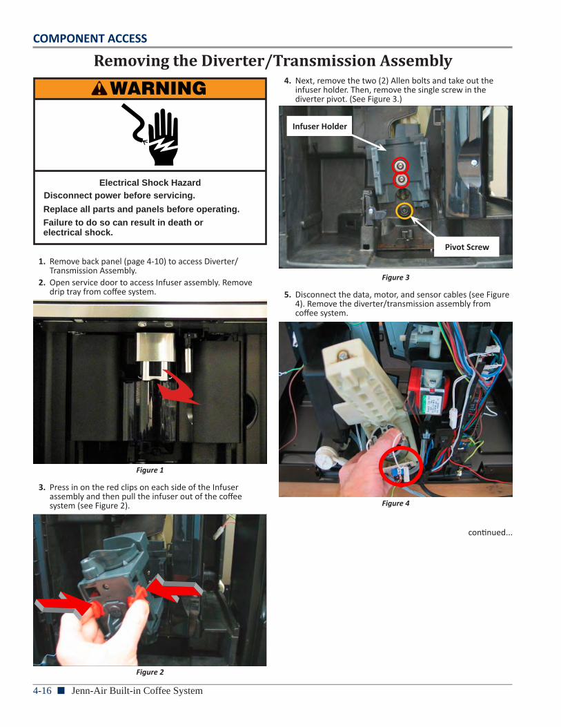
4-16 n Jenn-Air Built-in Coffee System
COMPONENT ACCESS
WARNING
Electrical Shock HazardDisconnect power before servicing.
Failure to do so can result in death orelectrical shock.
Replace all parts and panels before operating.
Removing the Diverter/Transmission Assembly
1. Remove back panel (page 4-10) to access Diverter/Transmission Assembly.
2. Open service door to access Infuser assembly. Remove drip tray from coffee system.
Figure 1
3. Press in on the red clips on each side of the Infuser assembly and then pull the infuser out of the coffee system (see Figure 2).
Figure 2
4. Next, remove the two (2) Allen bolts and take out the infuser holder. Then, remove the single screw in the diverter pivot. (See Figure 3.)
Figure 3
5. Disconnect the data, motor, and sensor cables (see Figure 4). Remove the diverter/transmission assembly from coffee system.
Figure 4
continued...
Infuser Holder
Pivot Screw
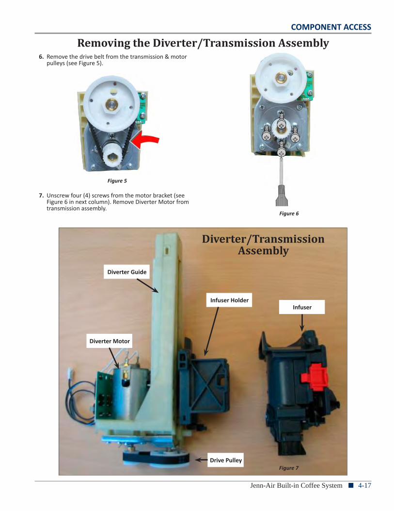
COMPONENT ACCESS
Jenn-Air Built-in Coffee System n 4-17
Removing the Diverter/Transmission Assembly6. Remove the drive belt from the transmission & motor
pulleys (see Figure 5).
Figure 5
7. Unscrew four (4) screws from the motor bracket (see Figure 6 in next column). Remove Diverter Motor from transmission assembly.
Figure 6
Diverter Motor
Diverter Guide
Drive Pulley
InfuserInfuser Holder
Diverter/Transmission Assembly
Figure 7
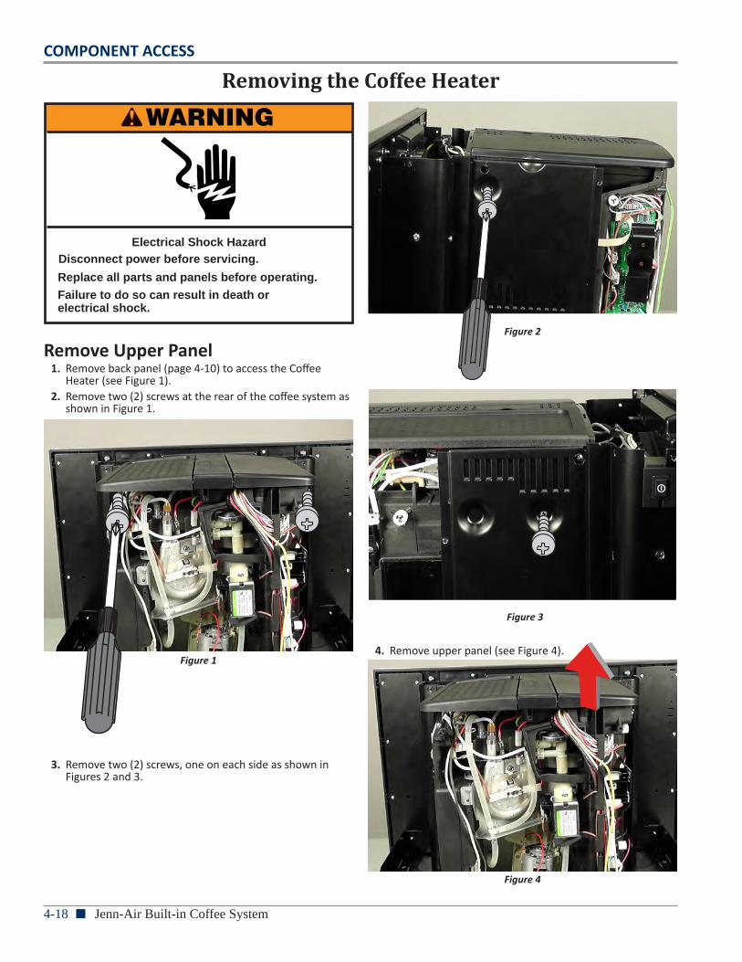
4-18 n Jenn-Air Built-in Coffee System
COMPONENT ACCESS
Removing the Coffee Heater
WARNING
Electrical Shock HazardDisconnect power before servicing.
Failure to do so can result in death orelectrical shock.
Replace all parts and panels before operating.
Remove Upper Panel1. Remove back panel (page 4-10) to access the Coffee
Heater (see Figure 1). 2. Remove two (2) screws at the rear of the coffee system as
shown in Figure 1.
Figure 1
3. Remove two (2) screws, one on each side as shown in Figures 2 and 3.
Figure 2
Figure 3
4. Remove upper panel (see Figure 4).
Figure 4
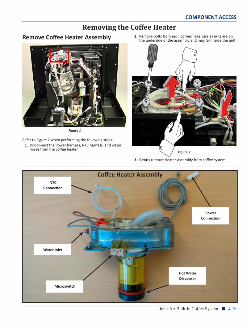
COMPONENT ACCESS
Jenn-Air Built-in Coffee System n 4-19
Removing the Coffee Heater
Power Connection
NTCConnection
Microswitch
Hot Water Dispenser
Coffee Heater Assembly
Water Inlet
Remove Coffee Heater Assembly
Figure 1
Refer to Figure 2 when performing the following steps. 1. Disconnect the Power harness, NTC harness, and water
hoses from the coffee heater.
2. Remove bolts from each corner. Take care as nuts are on the underside of the assembly and may fall inside the unit.
Figure 2
3. Gently remove Heater Assembly from coffee system.
4-20 n Jenn-Air Built-in Coffee System
COMPONENT ACCESS
WARNING
Electrical Shock HazardDisconnect power before servicing.
Failure to do so can result in death orelectrical shock.
Replace all parts and panels before operating.
Removing the Display Board & 2-Way Valve
Remove Display PCB 1. First, perform preparation procedure on page 4-8, “Before
Disassembling the Coffee System” prior to performing the following steps.
2. Next, perform the procedures to “Removing the Fan Panel” on page 4-9.
3. Then, perform the procedures to “Removing the Back Panel” on page 4-10.
Figure 1
4. Remove 14 screws, seven (7) from each side (see Figures 2 and 3).
Figure 2
Figure 3
COMPONENT ACCESS
Jenn-Air Built-in Coffee System n 4-21
Removing the Display Board & 2-Way Valve5. Remove four (4) screws from the bottom of the coffee
system (see Figure 4).
Figure 4
6. Remove two (2) screws from the left side of coffee system (see Figure 5).
Figure 5
7. Remove two (2) screws from the right side of coffee system (see Figure 6).
Figure 6
8. From the front of the coffee system, remove the three (3) screws located above the service door, underneath the control/display panel. Refer to Figure 7 for screw locations.
Figure 7
4-22 n Jenn-Air Built-in Coffee System
COMPONENT ACCESS
Removing the Display Board & 2-Way Valve9. Remove one (1) screw from inside the upper-right
compartment (see Figure 8).
Figure 8
10. Remove one (1) screw from inside the upper-left compartment (see Figure 9).
Figure 9
11. Disconnect the harnesses and wiring to the front panel. Then, lift up and remove front panel from coffee system. Refer to Figures 10, 11 & 12.
Figure 10
Figure 11
Figure 12 - Front Panel
COMPONENT ACCESS
Jenn-Air Built-in Coffee System n 4-23
Removing the Display Board & 2-Way Valve12. Disconnect the harness from the Display PCB. Unscrew
two (2) screws to remove the Display PCB from front panel (see Figure 13).
Figure 13
Remove 2-Way Valve1. Locate and remove the two (2) screws illustrated in Figure 1.
Figure 1
2. Remove the metal guide as illustrated in Figure 2.
Figure 2
Refer to Figure 3 when performing the following 3 steps. 3. Disconnect the wiring from the solenoid valve. 4. Disconnect the two (2) hoses from the solenoid valve. 5. Unscrew the two (2) screws to remove the solenoid valve.
Figure 3
4-24 n Jenn-Air Built-in Coffee System
COMPONENT ACCESS
WARNING
Electrical Shock HazardDisconnect power before servicing.
Failure to do so can result in death orelectrical shock.
Replace all parts and panels before operating.
Removing the Grinder Assembly
1. With a small screwdriver, remove the cap from the Grinder knob, then remove the screw (see Figure 1).
Figure 1
2. Remove the finger guard. Then remove the coffee bean storage area from the grinder by removing the screws illustrated in Figure 2.
Figure 2
3. To remove the grinder assembly, remove the three (3) screws shown in Figure 3.
Figure 3
4. Then, disconnect the motor terminals from the control board terminals “F2” and “F7.”
L L L L
N
F5
F7
F8F9
J5
J2J7J8
J13
J6J12
J4
J1
F4 F3 F2 F1
Figure 4 - Grinder Motor Connections on Main Board
GrinderMotor
MainBoard
F7
F2
COMPONENT ACCESS
Jenn-Air Built-in Coffee System n 4-25
WARNING
Electrical Shock HazardDisconnect power before servicing.
Failure to do so can result in death orelectrical shock.
Replace all parts and panels before operating.
Grinder Setup
1. Turn the white shaft clockwise till it stops (see Figure 1).2. Remove the upper part of the grinder by pulling it
upwards (see Figure 1).
Figure 1
3. Verify the position of the white gasket (must be positioned as the one shown in Figure 2).
Figure 2
4. Turn the white shaft counterclockwise till it stops; then, pull up on shaft to remove it (see Figure 3).
Figure 3
5. Now the grind setting can be changed. To increase the coarseness of the grind (thicker), turn the gear counter clockwise* (see Figure 4).
Figure 4
6. To decrease the coarseness of the grind (finer), turn the gear clockwise*.
7. Insert the white shaft, making sure its larger notch is aligned with the one on the grinder (see Figure 5).
Figure 5Continued...
1
2
3
4
5
(*) Before changing the setting, check and mark the initial position of the metal ball you see through the holes on the white ring. Change the setting carefully by turning the white ring a maximum of one or two steps (one or two holes) either way as required.
7
5
7
4-26 n Jenn-Air Built-in Coffee System
COMPONENT ACCESS 8. Turn the shaft clockwise till it stops to insert the
upper gear. Then, enter the mill by turning back counterclockwise until it stops (see Figure 6).
Figure 6
88
9. Insert the locking ring in the right position (see Figure 7).
Figure 7
9
Notes
DIAGNOSTICS & TROUBLESHOOTING
Jenn-Air Built-in Coffee System n 5-1
Section 5:Diagnostics & TroubleshootingThis section provides diagnostic, fault codes, and troubleshooting information for the “Jenn-Air Built-in Coffee System.”
n Safety First
n Control Panel
n Load Test Mode
n Display Test Mode
n Customer Instruct / Technical Faults
n Wiring Diagram
n Ladder Diagram
n Main Board
n LED/Fan PCB
n Plumbing Diagram
n Measuring Coffee Temperature
n Component Testing Chart
n Strip Circuits
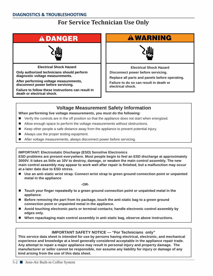
5-2 n Jenn-Air Built-in Coffee System
DIAGNOSTICS & TROUBLESHOOTING
For Service Technician Use Only
Voltage Measurement Safety InformationWhen performing live voltage measurements, you must do the following:
n Verify the controls are in the off position so that the appliance does not start when energized. n Allow enough space to perform the voltage measurements without obstructions. n Keep other people a safe distance away from the appliance to prevent potential injury. n Always use the proper testing equipment. n After voltage measurements, always disconnect power before servicing.
IMPORTANT: Electrostatic Discharge (ESD) Sensitive Electronics ESD problems are present everywhere. Most people begin to feel an ESD discharge at approximately 3000V. It takes as little as 10V to destroy, damage, or weaken the main control assembly. The new main control assembly may appear to work well after repair is finished, but a malfunction may occur at a later date due to ESD stress.
n Use an anti-static wrist strap. Connect wrist strap to green ground connection point or unpainted metal in the appliance
-OR-
n Touch your finger repeatedly to a green ground connection point or unpainted metal in the appliance.
n Before removing the part from its package, touch the anti-static bag to a green ground connection point or unpainted metal in the appliance.
n Avoid touching electronic parts or terminal contacts; handle electronic control assembly by edges only.
n When repackaging main control assembly in anti-static bag, observe above instructions.
IMPORTANT SAFETY NOTICE — “For Technicians only” This service data sheet is intended for use by persons having electrical, electronic, and mechanical experience and knowledge at a level generally considered acceptable in the appliance repair trade. Any attempt to repair a major appliance may result in personal injury and property damage. The manufacturer or seller cannot be responsible, nor assume any liability for injury or damage of any kind arising from the use of this data sheet.
WARNING
Electrical Shock HazardDisconnect power before servicing.
Failure to do so can result in death orelectrical shock.
Replace all parts and panels before operating.
DANGER
Electrical Shock Hazard
Only authorized technicians should perform diagnostic voltage measurements.
After performing voltage measurements, disconnect power before servicing.
Failure to follow these instructions can result in death or electrical shock.
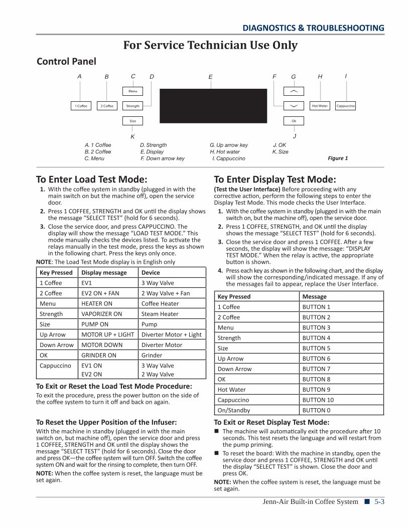
DIAGNOSTICS & TROUBLESHOOTING
Jenn-Air Built-in Coffee System n 5-3
For Service Technician Use OnlyControl Panel
To Enter Load Test Mode:1. With the coffee system in standby (plugged in with the
main switch on but the machine off), open the service door.
2. Press 1 COFFEE, STRENGTH and OK until the display shows the message “SELECT TEST” (hold for 6 seconds).
3. Close the service door, and press CAPPUCCINO. The display will show the message “LOAD TEST MODE.” This mode manually checks the devices listed. To activate the relays manually in the test mode, press the keys as shown in the following chart. Press the keys only once.
NOTE: The Load Test Mode display is in English only
Key Pressed Display message Device1 Coffee EV1 3 Way Valve2 Coffee EV2 ON + FAN 2 Way Valve + FanMenu HEATER ON Coffee HeaterStrength VAPORIZER ON Steam HeaterSize PUMP ON Pump Up Arrow MOTOR UP + LIGHT Diverter Motor + LightDown Arrow MOTOR DOWN Diverter MotorOK GRINDER ON GrinderCappuccino EV1 ON
EV2 ON3 Way Valve2 Way Valve
To Exit or Reset the Load Test Mode Procedure:To exit the procedure, press the power button on the side of the coffee system to turn it off and back on again.
To Reset the Upper Position of the Infuser:With the machine in standby (plugged in with the main switch on, but machine off), open the service door and press 1 COFFEE, STRENGTH and OK until the display shows the message “SELECT TEST” (hold for 6 seconds). Close the door and press OK—the coffee system will turn OFF. Switch the coffee system ON and wait for the rinsing to complete, then turn OFF. NOTE: When the coffee system is reset, the language must be set again.
To Enter Display Test Mode:(Test the User Interface) Before proceeding with any corrective action, perform the following steps to enter the Display Test Mode. This mode checks the User Interface.
1. With the coffee system in standby (plugged in with the main switch on, but the machine off), open the service door.
2. Press 1 COFFEE, STRENGTH, and OK until the display shows the message “SELECT TEST” (hold for 6 seconds).
3. Close the service door and press 1 COFFEE. After a few seconds, the display will show the message: “DISPLAY TEST MODE.” When the relay is active, the appropriate button is shown.
4. Press each key as shown in the following chart, and the display will show the corresponding/indicated message. If any of the messages fail to appear, replace the User Interface.
Key Pressed Message1 Coffee BUTTON 12 Coffee BUTTON 2Menu BUTTON 3Strength BUTTON 4Size BUTTON 5Up Arrow BUTTON 6Down Arrow BUTTON 7OK BUTTON 8Hot Water BUTTON 9Cappuccino BUTTON 10On/Standby BUTTON 0
To Exit or Reset Display Test Mode: n The machine will automatically exit the procedure after 10
seconds. This test resets the language and will restart from the pump priming.
n To reset the board: With the machine in standby, open the service door and press 1 COFFEE, STRENGTH and OK until the display “SELECT TEST” is shown. Close the door and press OK.
NOTE: When the coffee system is reset, the language must be set again.
FOR SERVICE TECHNICIAN’S USE ONLY
Parts And FeaturesRear view Service Door
Control Panel
W10629091A FOR SERVICE TECHNICIAN’S USE ONLY
DANGER
Electrical Shock Hazard
Only authorized technicians should perform diagnostic voltage measurements.
After performing voltage measurements, disconnect power before servicing.
Failure to follow these instructions can result in death or electrical shock.
WARNING
Electrical Shock Hazard
Disconnect power before servicing.
Replace all parts and panels before operating.
Failure to do so can result in death or electrical shock.
Voltage Measurement Safety InformationWhen performing live voltage measurements, you must do the following:
� Verify the controls are in the off position so that the appliance does not start when energized.
� Allow enough space to perform the voltage measurements without obstructions.
� Keep other people a safe distance away from the appliance to prevent potential injury.
� Always use the proper testing equipment.
� After voltage measurements, always disconnect power before servicing.
Tech Sheet Do not discard
A. Main On/Off Switch
A
A. Coffee spout B. Service door
A
B
A. 1 CoffeeB. 2 CoffeeC. Menu
D. StrengthE. DisplayF. Down arrow key
G. Up arrow keyH. Hot waterI. Cappuccino
J. OKK. Size
A B C D E G H I
JK
F
Figure 1
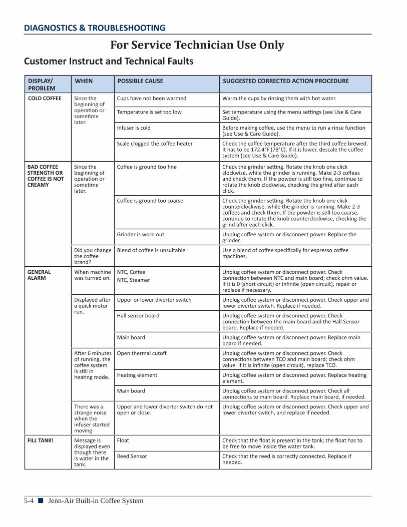
5-4 n Jenn-Air Built-in Coffee System
DIAGNOSTICS & TROUBLESHOOTING
For Service Technician Use OnlyCustomer Instruct and Technical Faults
DISPLAY/PROBLEM
WHEN POSSIBLE CAUSE SUGGESTED CORRECTED ACTION PROCEDURE
COLD COFFEE Since the beginning of operation or sometime later.
Cups have not been warmed Warm the cups by rinsing them with hot water.
Temperature is set too low Set temperature using the menu settings (see Use & Care Guide).
Infuser is cold Before making coffee, use the menu to run a rinse function (see Use & Care Guide).
Scale clogged the coffee heater Check the coffee temperature after the third coffee brewed. It has to be 172.4°F (78°C). If it is lower, descale the coffee system (see Use & Care Guide).
BAD COFFEE STRENGTH OR COFFEE IS NOT CREAMY
Since the beginning of operation or sometime later.
Coffee is ground too fine Check the grinder setting. Rotate the knob one click clockwise, while the grinder is running. Make 2-3 coffees and check them. If the powder is still too fine, continue to rotate the knob clockwise, checking the grind after each click.
Coffee is ground too coarse Check the grinder setting. Rotate the knob one click counterclockwise, while the grinder is running. Make 2-3 coffees and check them. If the powder is still too coarse, continue to rotate the knob counterclockwise, checking the grind after each click.
Grinder is worn out Unplug coffee system or disconnect power. Replace the grinder.
Did you change the coffee brand?
Blend of coffee is unsuitable Use a blend of coffee specifically for espresso coffee machines.
GENERAL ALARM
When machine was turned on.
NTC, CoffeeNTC, Steamer
Unplug coffee system or disconnect power. Check connection between NTC and main board; check ohm value. If it is 0 (short circuit) or infinite (open circuit), repair or replace if necessary.
Displayed after a quick motor run.
Upper or lower diverter switch Unplug coffee system or disconnect power. Check upper and lower diverter switch. Replace if needed.
Hall sensor board Unplug coffee system or disconnect power. Check connection between the main board and the Hall Sensor board. Replace if needed.
Main board Unplug coffee system or disconnect power. Replace main board if needed.
After 6 minutes of running, the coffee system is still in heating mode.
Open thermal cutoff Unplug coffee system or disconnect power. Check connections between TCO and main board; check ohm value. If it is infinite (open circuit), replace TCO.
Heating element Unplug coffee system or disconnect power. Replace heating element.
Main board Unplug coffee system or disconnect power. Check all connections to main board. Replace main board, if needed.
There was a strange noise when the infuser started moving
Upper and lower diverter switch do not open or close.
Unplug coffee system or disconnect power. Check upper and lower diverter switch, and replace if needed.
FILL TANK! Message is displayed even though there is water in the tank.
Float Check that the float is present in the tank; the float has to be free to move inside the water tank.
Reed Sensor Check that the reed is correctly connected. Replace if needed.
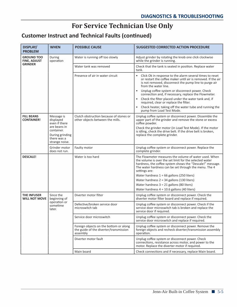
DIAGNOSTICS & TROUBLESHOOTING
Jenn-Air Built-in Coffee System n 5-5
For Service Technician Use OnlyCustomer Instruct and Technical Faults (continued)
DISPLAY/PROBLEM
WHEN POSSIBLE CAUSE SUGGESTED CORRECTED ACTION PROCEDURE
GROUND TOO FINE, ADJUST GRINDER
During operation
Water is running off too slowly Adjust grinder by rotating the knob one click clockwise while the grinder is running.
Water tank was removed Check that the tank is seated in position. Replace water tank.
Presence of air in water circuit • Click Ok in response to the alarm several times to reset or restart the coffee maker until air is removed. If the air is not removed, disconnect the pump line to purge air from the water line.
• Unplug coffee system or disconnect power. Check connection and, if necessary, replace the Flowmeter.
• Check the filter placed under the water tank and, if required, clear or replace the filter.
• Check heater, taking off the water tube and running the pump from Load Test Mode.
FILL BEANS CONTAINER!
Message is displayed even if there are beans in container. During grinding there was a strange noise.
Clutch obstruction because of stones or other objects between the mills.
Unplug coffee system or disconnect power. Dissemble the upper part of the grinder and remove the stone or excess coffee powder.Check the grinder motor (in Load Test Mode). If the motor is idling, check the drive belt. If the drive belt is broken, replace the complete grinder.
Grinder motor does not run.
Faulty motor Unplug coffee system or disconnect power. Replace the complete grinder.
DESCALE! Water is too hard The Flowmeter measures the volume of water used. When the volume is over the set limit for the selected water hardness, the coffee system shows the “Descale!” message. The water hardness can be set through the menu. The 4 settings are:Water hardness 1 = 66 gallons (250 liters)Water hardness 2 = 34 gallons (130 liters)Water hardness 3 = 21 gallons (80 liters)Water hardness 4 = 10.6 gallons (40 liters)
THE INFUSER WILL NOT MOVE
Since the beginning of operation or sometime later.
Diverter motor filter Unplug coffee system or disconnect power. Check the diverter motor filter board and replace if required.
Defective/broken service door microswitch tab
Unplug coffee system or disconnect power. Check if the service door microswitch tab is broken and replace the service door if required.
Service door microswitch Unplug coffee system or disconnect power. Check the service door microswitch and replace if required.
Foreign objects on the bottom or along the guide of the diverter/transmission assembly
Unplug coffee system or disconnect power. Remove the foreign objects and recheck diverter/transmission assembly operation.
Diverter motor fault Unplug coffee system or disconnect power. Check connections, resistance across motor, and power to the motor. Replace the diverter motor if required.
Main board Check connections and if necessary, replace Main board.
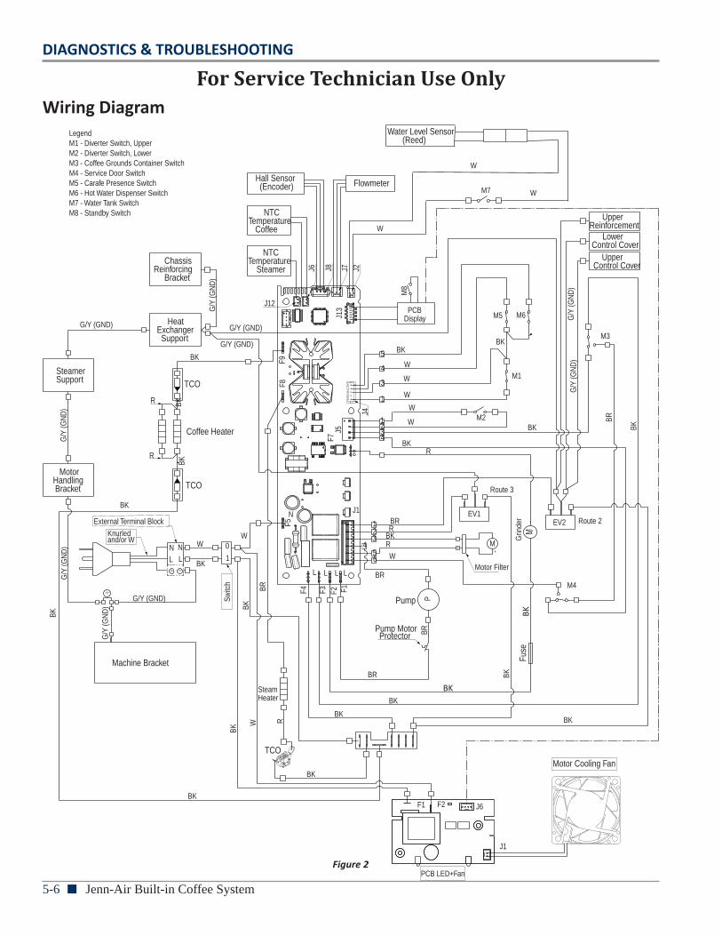
5-6 n Jenn-Air Built-in Coffee System
DIAGNOSTICS & TROUBLESHOOTING
For Service Technician Use OnlyWiring Diagram
ChassisReinforcing Bracket
Heat Exchanger Support
SteamerSupport
MotorHandling Bracket
Machine Bracket
EV1
Upper Reinforcement LowerControl Cover Upper Control Cover
BK
NTCTemperature Steamer
NTC Temperature Coffee
Hall Sensor (Encoder)
J12
TCO
BKFlowmeter
PCB Display
Coffee Heater
R
BK
TCO
WW
External Terminal Block
BK
Switc
h
BK
BK
N N
L L
0
1
TCO
SteamHeater
BK
BK
BK
Pump
Pump Motor Protector
BR
W R
P
F1 F2 J6
J1
PCB LED+Fan
Motor Cooling Fan
BK
BR
BK
Fuse
BK
BR
F4 F3 F2 F1
BRL L L LMotor Filter
M4
M
65
4321 BR
RBKR
W
J1
Route 3
Grin
der
M EV2 Route 2
N
F5
F7
Knurled and/or W
M3G/Y (GND)
G/Y
(GN
D)
G/Y
(GN
D)
G/Y (GND)
G/Y (GND)
G/Y
(GN
D)
G/Y
(GN
D)
G/Y (GND)
G/Y
(GN
D)
G/Y
(GN
D)
BK
R
BK
BK
BK
LegendM1 - Diverter Switch, UpperM2 - Diverter Switch, Lower M3 - Coffee Grounds Container SwitchM4 - Service Door SwitchM5 - Carafe Presence SwitchM6 - Hot Water Dispenser SwitchM7 - Water Tank SwitchM8 - Standby Switch
F8F9
J5
J4
J6 J8 J7 J2
J13
BR
BK
Water Level Sensor (Reed)
W
W
W
W
W
BKR
BK5
4
3
1
1234
M2
M1
M5 M6
M7
W
W
W
M8
Figure 2
BK
BK
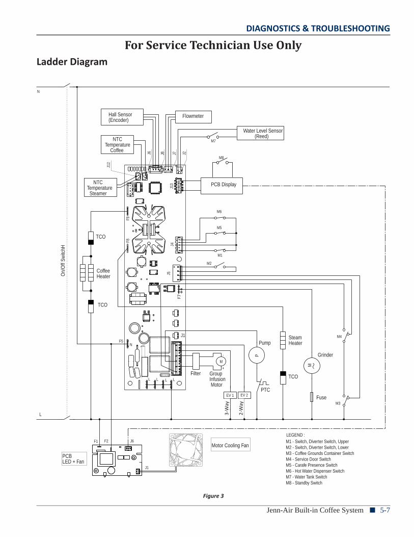
DIAGNOSTICS & TROUBLESHOOTING
Jenn-Air Built-in Coffee System n 5-7
For Service Technician Use OnlyLadder Diagram
N
Hall Sensor(Encoder)
Flowmeter
Water Level Sensor (Reed) NTC
Temperature Coffee
J6 J8 J7 J2
J13 NTC
Temperature Steamer
J12
PCB Display
F9F8
TCO
On/
Off
Switc
hH
CoffeeHeater
M6
M5
J4
M1
M2
J5
TCO
F7
Pump
P
J1
M
GroupInfusion Motor
Filter
F5N
Grinder
M4
Fuse
M
TCO
PTCEV 1 EV 2
L L L L
Way
Out
Stea
m
SteamHeater
L
PCBLED + Fan
F1 F2 J6
J1
Motor Cooling Fan
M3
LEGEND :M1 - Switch, Diverter Switch, UpperM2 - Switch, Diverter Switch, LowerM3 - Coffee Grounds Container SwitchM4 - Service Door SwitchM5 - Carafe Presence SwitchM6 - Hot Water Dispenser SwitchM7 - Water Tank SwitchM8 - Standby Switch
M8
M7
F7
Figure 3
3-W
ay
2-W
ay
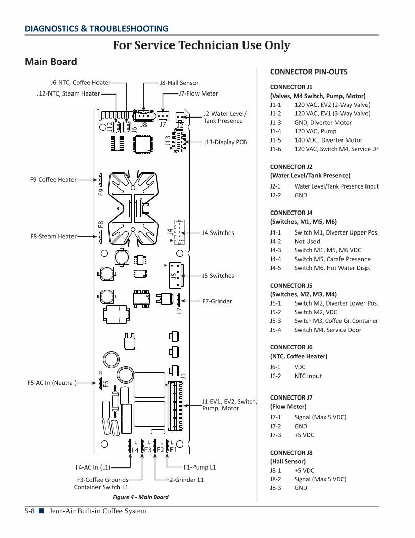
5-8 n Jenn-Air Built-in Coffee System
DIAGNOSTICS & TROUBLESHOOTING
For Service Technician Use OnlyMain Board
L L L L
N
F5
F7
F8F9
J5
J2J7J8
J13
J6J12
J4
J1
F4 F3 F2 F1
J8-Hall SensorJ7-Flow Meter
J2-Water Level/Tank Presence
J13-Display PCB
J4-Switches
J5-Switches
F7-Grinder
J1-EV1, EV2, Switch,Pump, Motor
F1-Pump L1
F2-Grinder L1
F4-AC In (L1)
F3-Coffee Grounds Container Switch L1
F5-AC In (Neutral)
F8-Steam Heater
F9-Coffee Heater
J12-NTC, Steam Heater
J6-NTC, Coffee HeaterCONNECTOR PIN-OUTS
CONNECTOR J1(Valves, M4 Switch, Pump, Motor)J1-1 120 VAC, EV2 (2-Way Valve)J1-2 120 VAC, EV1 (3-Way Valve)J1-3 GND, Diverter MotorJ1-4 120 VAC, PumpJ1-5 140 VDC, Diverter MotorJ1-6 120 VAC, Switch M4, Service Dr
CONNECTOR J2(Water Level/Tank Presence)
J2-1 Water Level/Tank Presence Input J2-2 GND
CONNECTOR J4(Switches, M1, M5, M6)
J4-1 Switch M1, Diverter Upper Pos. J4-2 Not UsedJ4-3 Switch M1, M5, M6 VDCJ4-4 Switch M5, Carafe PresenceJ4-5 Switch M6, Hot Water Disp.
CONNECTOR J5(Switches, M2, M3, M4)J5-1 Switch M2, Diverter Lower Pos. J5-2 Switch M2, VDCJ5-3 Switch M3, Coffee Gr. ContainerJ5-4 Switch M4, Service Door
CONNECTOR J6(NTC, Coffee Heater)
J6-1 VDC J6-2 NTC Input
CONNECTOR J7(Flow Meter)
J7-1 Signal (Max 5 VDC)J7-2 GNDJ7-3 +5 VDC
CONNECTOR J8(Hall Sensor)J8-1 +5 VDCJ8-2 Signal (Max 5 VDC)J8-3 GND
Figure 4 - Main Board
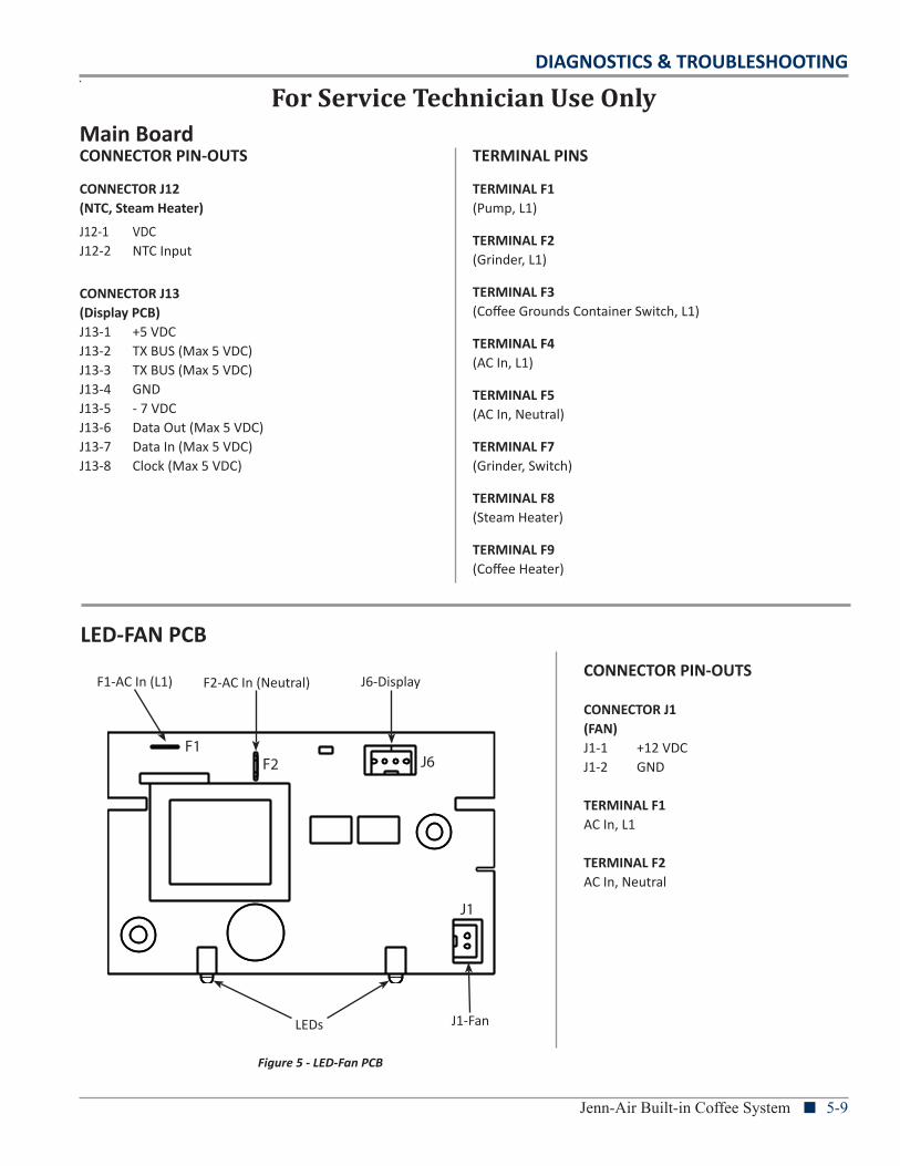
DIAGNOSTICS & TROUBLESHOOTING
Jenn-Air Built-in Coffee System n 5-9
For Service Technician Use OnlyMain Board
LED-FAN PCB
F1F2 J6
J1
J6-Display
J1-Fan
F1-AC In (L1) F2-AC In (Neutral)
LEDs
CONNECTOR PIN-OUTS
CONNECTOR J1(FAN)J1-1 +12 VDCJ1-2 GND
TERMINAL F1AC In, L1
TERMINAL F2AC In, Neutral
CONNECTOR PIN-OUTS
CONNECTOR J12 (NTC, Steam Heater)
J12-1 VDC J12-2 NTC Input
CONNECTOR J13(Display PCB)J13-1 +5 VDCJ13-2 TX BUS (Max 5 VDC)J13-3 TX BUS (Max 5 VDC)J13-4 GNDJ13-5 - 7 VDCJ13-6 Data Out (Max 5 VDC)J13-7 Data In (Max 5 VDC)J13-8 Clock (Max 5 VDC)
TERMINAL PINS
TERMINAL F1(Pump, L1)
TERMINAL F2(Grinder, L1)
TERMINAL F3(Coffee Grounds Container Switch, L1)
TERMINAL F4(AC In, L1)
TERMINAL F5(AC In, Neutral)
TERMINAL F7(Grinder, Switch)
TERMINAL F8(Steam Heater) TERMINAL F9(Coffee Heater)
Figure 5 - LED-Fan PCB
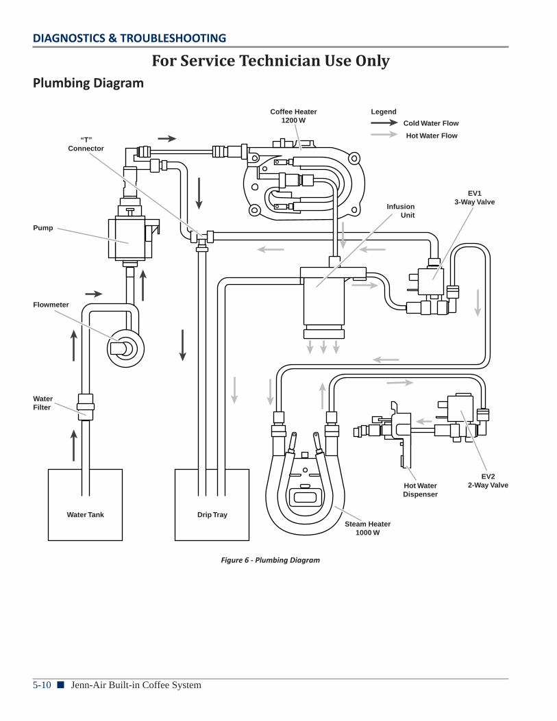
5-10 n Jenn-Air Built-in Coffee System
DIAGNOSTICS & TROUBLESHOOTING
For Service Technician Use OnlyPlumbing Diagram
Water Tank Drip TraySteam Heater
1000 W
WaterFilter
Flowmeter
Pump
“T”Connector
EV13-Way Valve
EV22-Way Valve
InfusionUnit
Coffee Heater1200 W
Hot WaterDispenser
Hot Water Flow
Cold Water Flow
Legend
Figure 6 - Plumbing Diagram
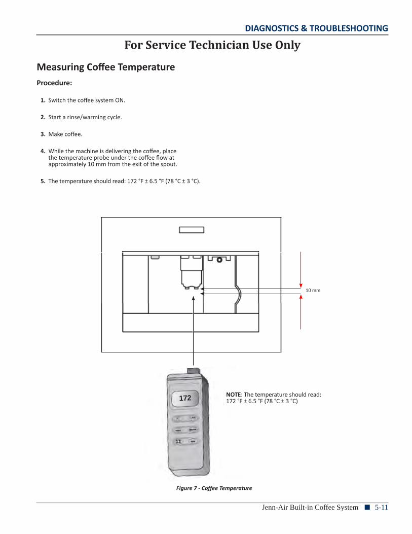
DIAGNOSTICS & TROUBLESHOOTING
Jenn-Air Built-in Coffee System n 5-11
172
10 mm
Procedure:
1. Switch the coffee system ON.
2. Start a rinse/warming cycle.
3. Make coffee.
4. While the machine is delivering the coffee, place the temperature probe under the coffee flow at approximately 10 mm from the exit of the spout.
5. The temperature should read: 172 °F ± 6.5 °F (78 °C ± 3 °C).
Measuring Coffee Temperature
For Service Technician Use Only
Figure 7 - Coffee Temperature
NOTE: The temperature should read: 172 °F ± 6.5 °F (78 °C ± 3 °C)
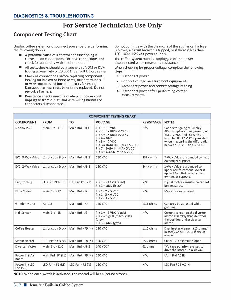
5-12 n Jenn-Air Built-in Coffee System
DIAGNOSTICS & TROUBLESHOOTING
For Service Technician Use OnlyComponent Testing Chart
Unplug coffee system or disconnect power before performing the following checks:
n A potential cause of a control not functioning is corrosion on connections. Observe connections and check for continuity with an ohmmeter.
n All tests/checks should be made with a VOM or DVM having a sensitivity of 20,000 Ω per volt DC or greater.
n Check all connections before replacing components, looking for broken or loose wires, failed terminals, or wires not pressed into connectors far enough. Damaged harness must be entirely replaced. Do not rework a harness.
n Resistance checks must be made with power cord unplugged from outlet, and with wiring harness or connectors disconnected.
Do not continue with the diagnosis of the appliance if a fuse is blown, a circuit breaker is tripped, or if there is less than 120+10%/-15% volt power supply.The coffee system must be unplugged or the power disconnected when measuring resistance.When checking for proper voltage, complete the following steps:
1. Disconnect power.2. Connect voltage measurement equipment.3. Reconnect power and confirm voltage reading.4. Disconnect power after performing voltage
measurements.
COMPONENT TESTING CHARTCOMPONENT FROM TO VOLTAGE RESISTANCE NOTESDisplay PCB Main Brd - J13 Main Brd - J13 Pin 1 = +5 VDC
Pin 2 = TX BUS (MAX 5V) Pin 3 = TX BUS (MAX 5V) Pin 4 = GND Pin 5 = - 7 VDC Pin 6 = DATA OUT (MAX 5 VDC) Pin 7 = DATA IN (MAX 5 VDC) Pin 8 = CLOCK (MAX 5 VDC)
N/A Connector going to Display PCB. Supplies circuit ground, +5 VDC, -7 VDC and transmission lines. NOTE: 12 VDC is provided when measuring the differential between +5 VDC and -7 VDC.
EV1, 3-Way Valve L1 Junction Block Main Brd - J1-2 120 VAC 458k ohms 3-Way Valve is grounded to heat exchanger support.
EV2, 2-Way Valve L1 Junction Block Main Brd - J1-1 120 VAC 444k ohms 2-Way Valve is grounded to upper reinforcement, lower & upper Main Brd cover, & heat exchanger support.
Fan, Cooling LED Fan PCB - J1 LED Fan PCB - J1 Pin 1 = +12 VDC (red) Pin 2 = GND (black)
N/A Digital motor - resistance cannot be measured.
Flow Meter Main Brd - J7 Main Brd - J7 Pin 1 - 2 = 5 VDC Pin 1 - 3 = 0 VDC Pin 2 - 3 = 5 VDC
N/A Measures water used.
Grinder Motor F2 (L1) Main Brd - F7 120 VAC 13.1 ohms Can only be adjusted while grinding.
Hall Sensor Main Brd - J8 Main Brd - J8 Pin 1 = +5 VDC (black) Pin 2 = Signal (max 5 VDC) (gray) Pin 3 = GND (gray)
N/A Current sensor on the diverter motor assembly that identifies the position of the diverter motor.
Coffee Heater L1 Junction Block Main Brd - F9 (N) 120 VAC 11.5 ohms Dual heater element (23.ohms/heater). Check TCO's if circuit is open.
Steam Heater L1 Junction Block Main Brd - F8 (N) 120 VAC 15.4 ohms Check TCO if circuit is open.
Diverter Motor Main Brd - J1-5 Main Brd - J1-3 140 VDC* 62 ohms *Voltage polarity reverses to drive the motor up & down.
Power In (Main Board)
Main Brd - F4 (L1) Main Brd - F5 (N) 120 VAC N/A Main Brd AC IN
Power In (LED Fan PCB)
LED Fan - F1 (L1) LED Fan - F2 (N) 120 VAC N/A LED Fan PCB AC IN
NOTE: When each switch is activated, the control will beep (sound a tone).
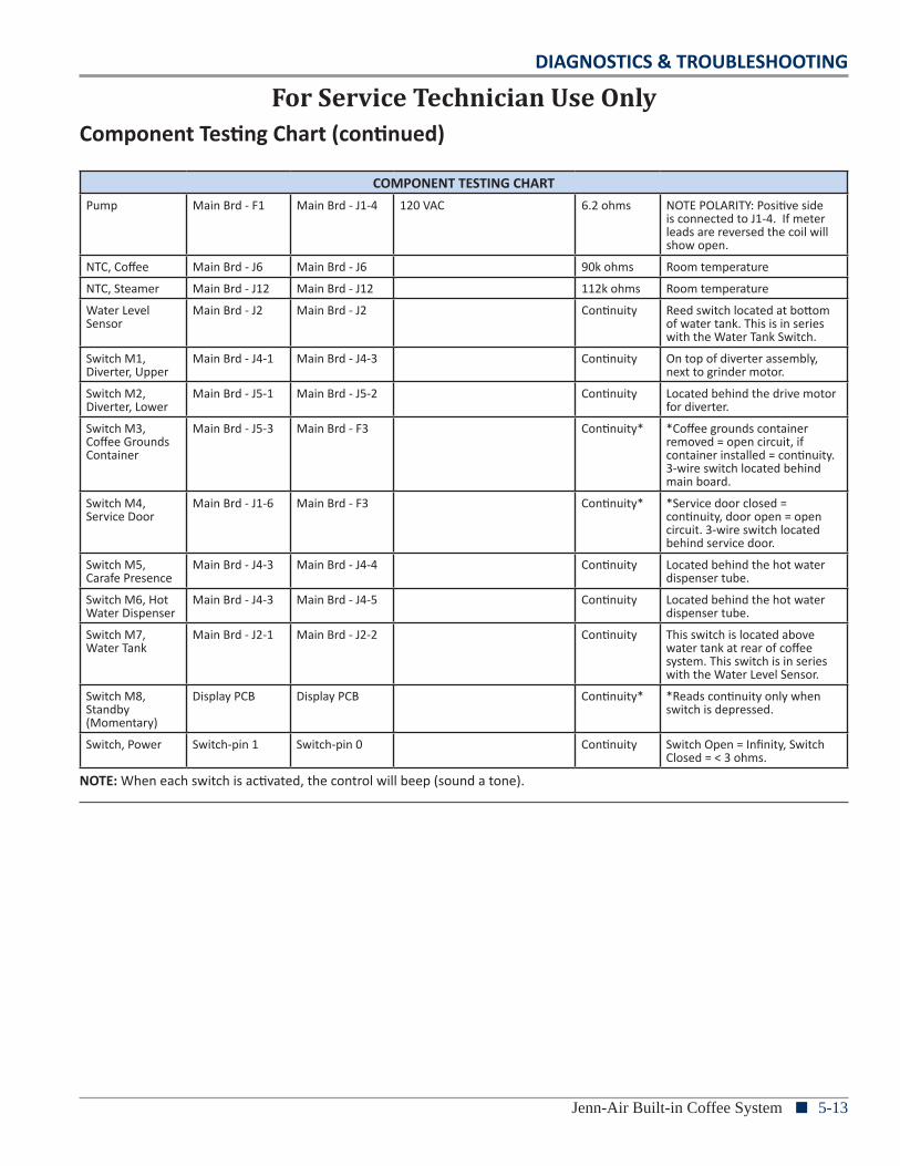
DIAGNOSTICS & TROUBLESHOOTING
Jenn-Air Built-in Coffee System n 5-13
COMPONENT TESTING CHARTPump Main Brd - F1 Main Brd - J1-4 120 VAC 6.2 ohms NOTE POLARITY: Positive side
is connected to J1-4. If meter leads are reversed the coil will show open.
NTC, Coffee Main Brd - J6 Main Brd - J6 90k ohms Room temperature
NTC, Steamer Main Brd - J12 Main Brd - J12 112k ohms Room temperature
Water Level Sensor
Main Brd - J2 Main Brd - J2 Continuity Reed switch located at bottom of water tank. This is in series with the Water Tank Switch.
Switch M1, Diverter, Upper
Main Brd - J4-1 Main Brd - J4-3 Continuity On top of diverter assembly, next to grinder motor.
Switch M2, Diverter, Lower
Main Brd - J5-1 Main Brd - J5-2 Continuity Located behind the drive motor for diverter.
Switch M3, Coffee Grounds Container
Main Brd - J5-3 Main Brd - F3 Continuity* *Coffee grounds container removed = open circuit, if container installed = continuity. 3-wire switch located behind main board.
Switch M4, Service Door
Main Brd - J1-6 Main Brd - F3 Continuity* *Service door closed = continuity, door open = open circuit. 3-wire switch located behind service door.
Switch M5, Carafe Presence
Main Brd - J4-3 Main Brd - J4-4 Continuity Located behind the hot water dispenser tube.
Switch M6, Hot Water Dispenser
Main Brd - J4-3 Main Brd - J4-5 Continuity Located behind the hot water dispenser tube.
Switch M7, Water Tank
Main Brd - J2-1 Main Brd - J2-2 Continuity This switch is located above water tank at rear of coffee system. This switch is in series with the Water Level Sensor.
Switch M8, Standby (Momentary)
Display PCB Display PCB Continuity* *Reads continuity only when switch is depressed.
Switch, Power Switch-pin 1 Switch-pin 0 Continuity Switch Open = Infinity, Switch Closed = < 3 ohms.
For Service Technician Use OnlyComponent Testing Chart (continued)
NOTE: When each switch is activated, the control will beep (sound a tone).
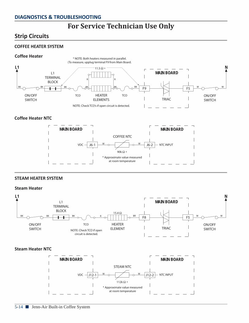
5-14 n Jenn-Air Built-in Coffee System
DIAGNOSTICS & TROUBLESHOOTING
For Service Technician Use OnlyStrip Circuits
COFFEE HEATER NTC
MAIN BOARDCOFFEE NTC
J6-1
MAIN BOARD
J6-2
90k
VDC NTC INPUT
* Approximate value measured at room temperature
W W
L1MAIN BOARD
N11.5
ON/OFF SWITCH
ON/OFF SWITCHTRIAC
HEATERELEMENTS
TCO
L1TERMINAL
BLOCK
COFFEE HEATER
F9 F5
TCO
* NOTE: Both heaters measured in parallel.(To measure, upplug terminal F9 from Main Board.
NOTE: Check TCO’s if open circuit is detected.
BK
R R
W WBK BK BK BKBK
L1MAIN BOARD
N
15.4
ON/OFF SWITCH
ON/OFF SWITCHTRIAC
HEATERELEMENT
TCO
L1TERMINAL
BLOCK
STEAM HEATER
F8 F5
NOTE: Check TCO if open circuit is detected.
BK BK BK R BR W W
STEAM HEATER NTC
MAIN BOARDSTEAM NTC
J12-1
MAIN BOARD
J12-2
112k
* Approximate value measured at room temperature
W W NTC INPUTVDC
COFFEE HEATER SYSTEM
STEAM HEATER SYSTEM
Steam Heater NTC
Steam Heater
Coffee Heater NTC
Coffee Heater
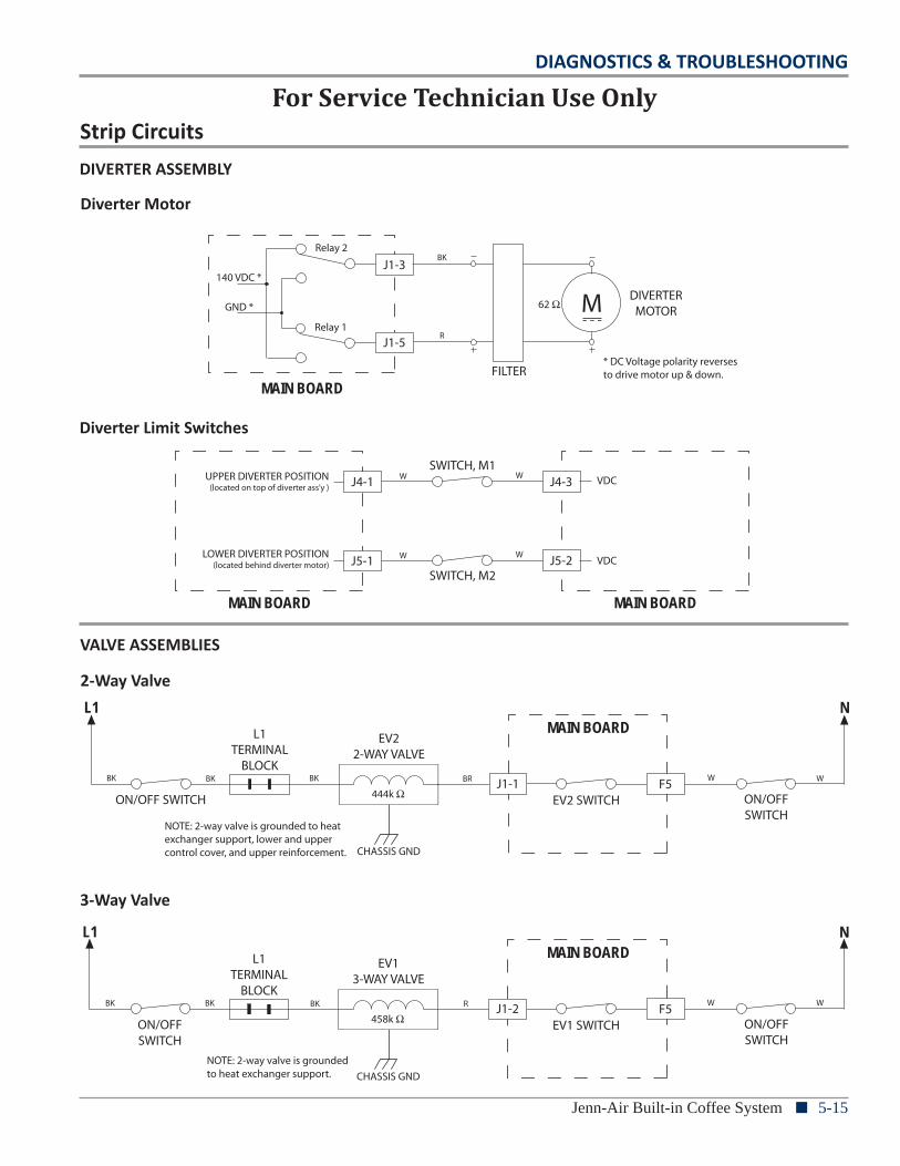
DIAGNOSTICS & TROUBLESHOOTING
Jenn-Air Built-in Coffee System n 5-15
For Service Technician Use Only
DIVERTER LIMIT SWITCHES
MAIN BOARD
J4-1
J5-1
J4-3
J5-2
SWITCH, M1
MAIN BOARD
SWITCH, M2
UPPER DIVERTER POSITION(located on top of diverter ass’y )
LOWER DIVERTER POSITION(located behind diverter motor)
W W
W W
VDC
VDC
DIVERTER MOTOR
DIVERTERMOTOR
MAIN BOARD
62
FILTER
J1-3
J1-5
M140 VDC *
Relay 1
Relay 2
* DC Voltage polarity reverses to drive motor up & down.
GND *
BK
R
L1MAIN BOARD
N
458k ON/OFF SWITCH
ON/OFF SWITCH
EV1 SWITCH
EV13-WAY VALVE
CHASSIS GND
L1TERMINAL
BLOCK
3-WAY VALVE
J1-2 F5
NOTE: 2-way valve is grounded to heat exchanger support.
BK BK BK R W W
L1MAIN BOARD
N
444k ON/OFF SWITCH ON/OFF SWITCH
EV2 SWITCH
EV22-WAY VALVE
CHASSIS GND
L1TERMINAL
BLOCK
2-WAY VALVE
J1-1 F5
NOTE: 2-way valve is grounded to heat exchanger support, lower and upper control cover, and upper reinforcement.
BK BK BK BR W W
Strip CircuitsDIVERTER ASSEMBLY
VALVE ASSEMBLIES
3-Way Valve
2-Way Valve
Diverter Limit Switches
Diverter Motor
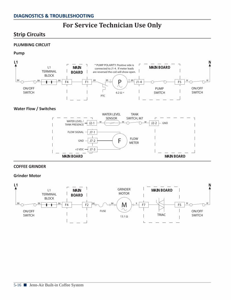
5-16 n Jenn-Air Built-in Coffee System
DIAGNOSTICS & TROUBLESHOOTING
L1MAIN BOARD
N
13.1
ON/OFF SWITCH
ON/OFF SWITCHTRIAC
M
L1TERMINAL
BLOCK
GRINDER
F7 F5F4 F2
MAIN BOARD
FUSE
GRINDERMOTOR
BK BK BK R W WBK BK
L1MAIN BOARD
N
6.2 ON/OFF SWITCH
ON/OFF SWITCH
PUMPSWITCH
P
PTC
L1TERMINAL
BLOCK
PUMP
J1-4 F5
* PUMP POLARITY: Positive side is connected to J1-4. If meter leads
are reversed the coil will show open.
F4 F1
MAIN BOARD
BK BK BK BR BR BR W W
WATER FLOW / SWITCHES
MAIN BOARD
FLOWMETER
J2-2
MAIN BOARD
TANK SWITCH, M7
J2-1
WATER LEVEL SENSOR
J7-2
J7-1
J7-3
F+5 VDC
GND
FLOW SIGNAL
WATER LEVEL / TANK PRESENCE
w w w GND
For Service Technician Use OnlyStrip Circuits
PLUMBING CIRCUIT
COFFEE GRINDER
Grinder Motor
Water Flow / Switches
Pump
PRODUCT SPECIFICATIONS &WARRANTY INFORMATION SOURCES
IN THE UNITED STATES:FOR PRODUCT SPECIFICATIONS AND WARRANTY INFORMATION CALL: 1-800-JENNAIR Website: (1-800-536-6247) www.jennair.com FOR TECHNICAL ASSISTANCE WHILE AT THE CUSTOMER’S HOME CALL:
THE TECHNICAL ASSISTANCE LINE: 1-800-832-7174
HAVE YOUR STORE NUMBER READY TO IDENTIFY YOU AS ANAUTHORIZED IN-HOME SERVICE PROFESSIONAL
FOR LITERATURE ORDERS (CUSTOMER EXPERIENCE CENTER): PHONE: 1-800-851-4605
FOR TECHNICAL INFORMATION AND SERVICE POINTERS: www.servicematters.com
IN CANADA:FOR PRODUCT SPECIFICATIONS AND WARRANTY INFORMATION CALL 1-800-JENNAIR Website: (1-800-536-6247) www.jennair.ca
FOR TECHNICAL ASSISTANCE WHILE AT THE CUSTOMER’S HOME CALL:THE TECHNICAL ASSISTANCE LINE: 1-800-488-4791
HAVE YOUR STORE NUMBER READY TO IDENTIFY YOU AS AN AUTHORIZED IN-HOME SERVICE PROFESSIONAL

Jenn-Air Built-in Coffee System
W10647095