Embed Size (px)
Citation preview
W0 Report 2399
STATUS OF IMPROVED MIL-G-10924,
GREASE, AUTOMOTIVE AND ARTILLERY (GAA) PROGRAM
DTICFebruary 1984 OTI1
* LL.J Approved for public release, distribution unlimited.
BeloirUnited States Army
BlorResearch &Development CenterFort Belvoir, Virginia 22060
84 09 27 014 7
Destroy this report when it is no longer needed.Do not return it to the originator.
The citation in this report of trade names of commercially avail-able products does not constitute official endorsement or approvalof the use of such products.
UNCLASSIFIED~ SECURITY CLASSIFICATION OF THIS PAGE (When nets rntered)_
REPORT DOCUMENTATION PAGE BEFOR COMPLTING O
1. REPORT NUMBER GOTACCESSION No. 3. RECIPIENT'S CATALOG NUMBER
2399 A____c/_________
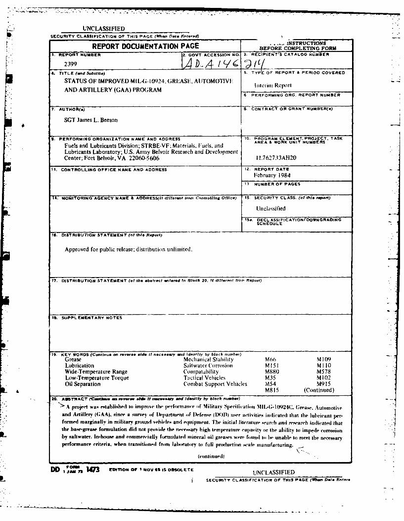
4. TITLE (and Subtitlo) 5.., TYPE OF REPORT A PERIOD COVEREDSTATUS OF IMPROVED MILA-I0924, GREiASE.. AIITOMOTIVF: I~iinRjn
AND~~~ ~ ~ ~ ~ ARILR GA RGA PERFORMING ORG. REPORT NUMBER
7. AUrNOR(a) S. CONTRACT OR GRANT NUMBER(a)
SGT James L. Beeson2
S. PERFORMING ORGANIZATION NAME AND ADDRESS 10. PROGRAM ELEMENT. PROJECT. TASK
Fuels and Lubricants Division; STRBE-VF; Materials, Fuels, and AE OKUI UBRLubricants Laboratory; U.S. Army Belvoir Research and DevelopmentCenter; Fort Belvoir, VA 22060-5 606 I L762733AH20
It. CONTROLLING OFFICE NAME AND ADDRESS 12. REPORT DATEFebruary 1984
11 NUMBER OF PAGES
14. MONITORING AGENCY NAME & ADDRESS(Il different trom Controlling Office) 15 SECURITY CLASS. (of this report)
Unclassified
IS&, DECLASSI FICATION/ DOWNGRADINGSCHEDULE
16. DISTRIBUTION STATEMENT (of this Report)
Approved for public release-, distribution unlimited.
17. DISTRIBUTION STATEMENT (of the abstract entered In Black 20. It differen~t fromn Report)
ISUPPLEMENTARY NOTES
19, KEY WORDS (Continue on reveresiadd. It neceseary and Identify by block number)Grease Mechanical Stability M60 M 109Lubrication Saltwater Corrosion MI151 Milo0Wide-Temperature Range Colnpatahility M890 M578Low-Temperature Torque Tactical Vehicles M35 M102Oil Separation Combat Support Vehicles \454 M915
a M815 (Continued)* 20. ANSTRACT (Cthue -w rover"sts Hf necesy and identffy by block nutbwr)
>.A pro~ject' was estabisehedt to improve the l~romneof Military S1tecificat ilol %,1,L-- I 924(:. (reatse, Automotiveand Artillery ((;AA). since a survey (of Department of lDefen.w (1)0)usra-i.teinctdIhtheurinte-formed marginally in military ground vehicle% anti equIipnment. TIhe initial literatuire search anti re-search indi-aled that.the base-grease formulation did not providie the necessary high tempe-ratulre capac-ity or the ablility to) impede corrosion
IL by saltwater. In-house and commercially formulated mineral oil greases were foulnd to be unable to meet the necessaryPerformance crteria, when transitioned from laboratory tel full production scale manufacturing.
(continued)
DD U 47 EVtITO"s OF I NOV GS IS OBSOLETE UCASFE
SECURITY CLASSIFICATIONt OF THIS PAGE (When Data lriters
UNCLASSIFIED
SECURITY CLASSIFICA. OF THIS PAGE(Wmmt Date 806110Dt
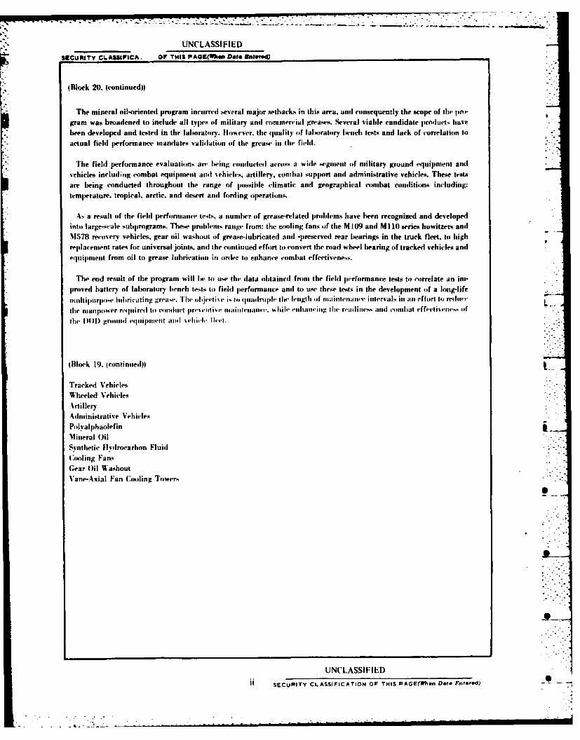
(Block 20. icontinued))
The mineral oil-oriented program incurred several major setback% in this area, anti consequently the scope of the pro-
gram was broadened to include all types oif military anti commercial greasesm. Several viable candidate pirodlucts have
been developed and tested in the laboratory. Hoamever. the quality of laboratory bench tests and lack of correlation toactual field performance mandates validation of the grease in the field.
The field performance evaluations are being conducted across a wide segulemt of military ground equipment antivehicles including combat equipment andi %ehicles, artillery, combat support andi adlministrative vehicles. These tests
are being conducted throughout the range of possible climatic and geographical combat conditions including:
temperature, tropical, arctic, and desert andi fording operations.
Aa result of the field performance tests, a number of grease-related prolems have been recognized and developedinto large-cale subprograms. These problems range from: the cooling fans oif the M 109 and MI 10 series howitzers and
Ml578 recovery vehicles, gear oil washout of grease-lubricated and] -preserved rear bearings, in the truck fleet, to high
replacement rates for universal joints, and the continued effort to convert the road wheel bearing of tracked vehicles and
equipment from oil to grease lubrication its (ordler to enhance conmbat effectiveness.
The end result of the program will lhe to use the data obtained front the field performance tests to correlate an im-proved battery of laboratory bench tests to field performance anti to use these tests in the development of a long-life
mulitipurpose lubricating grease. Thew olijecti%4 i.. top quadrauple the lengthill ot'aitemunice iuutervals its an effort to) reiliict
the manpower required to conduct lprv~voIti~v IIailteiaoce %%hile eihuuiuciag thle readiness mid comblat effectisenvs ofl
the DOD)1 groon 1l equoipment aod %eiclegh Ilvet.
(Block 19. (continued))
Tracked VehiclesWheeled VehiclesArtilleryAdministrative VehiclesPolyal phaolefinMineral Oil
Synthetic Hyvdrocarbson Fluid
C;ooling FansGear Oil Washout
Vane-Axial Fan Cooling Towers
UNCLASSIFIED
S SECURITY CLASSIFICATION OF THIS PAGE(W7In Date Entered) - 1

{-.%
CONTENTS
Section Title Page
TABLES iv
I BACKGROUND
II OBJECTIVE 2
III APPROACH 2
IV INTERIM PRODUCTS 4
V BROADENED APPROACH 5
VI UPDATING LABORATORY TEST METHODS 10
VII FIELD PERFORMANCE TESTING 10
VIII INITIAL RESULTS 20
IX CONCLUSIONS 21
APPENDICES
A. SALTWATER RUST PROTECTION METHOD 22B. LOW-TEMPERATURE TORQUE TESTING OF 25
AUTOMOTIVE WHEEL BEARING GREASEC. LIFE PERFORMANCE OF AUTOMOTIVE WHEEL 31
BEARING GREASESD. STATUS OF GEAR OIL WASHOUT OF WHEEL BEARING 34
GREASE IN TACTICAL VEHICLES PROJECT
E. LETTER REPORT-STATUS OF VANE-AXIAL FAN 51
Accession For
" NTIS GRA&ID I DTIC TA?DTI DTIC Tiom.ce"
ELECTES.!OCTI 3 ...
0 1 ' ~By .....
AvallabilitY Codes
ii - AvAi u. or
Dist Special.
1Ai' I
TABLES
Table Title Page
I Test Results, C'ode MF-002 61
2 Test Results. Code MF'-OOl1 8
3 Field Perfonnance Test and Vehicle IdentificationII
4 Field Performance Test and Vehicle Identification 13 -
5 Test Results. ('ode MI-020-" 14
6 Field Performance Test and Vehicle Identification 16
PL7 Field Performance Test and V'ehicle Identification 17
8 Field Perfonnance 'Vest and Vehicle Identification 18
STATUS OF IMPROVED) MIL-G-10924,
GREASE, AUTOMOTIVE AND ARTILLERY (GAA) PROGRAM
1. BACKGROUND
The original M SAG-10924 Grease, Automotive and Artillery (GAA) specification wasdeveloped in 1951 and was preceded by an assortment of ordnance and wheel bearing greasespecifications. The traditional formulation consisted of a 70 Sus at 2100 F viscositynaphthenic mineral oil thickened with a calcium or lithium soap. The specification has sinceundergone three previous revisions, each of which provided additional new specification re- - -
quirements and subsequent improvements in product performance. The additions included:four ball-wear tests, a water stability test to evaluate greases' consistency after exposure towater and mechanical shear stresses, and an anticorrosion requirement to enhance the preser-vative capabilities of the lubricant. MILG-10924 which is currently interchanged in STANAG1135 under NATO Code Number G-403, is a multipurpose, NLGI number two-consistencygrease intended for the lubrication and surface corrosion protection of all automotive and ar-tillery equipment operated in the -65' F to 1250 F ambient temperature range, (-65* F to2250 F temperature range). The grease may also be used in other applications within thetemperature range where an oxidation resistant and corrosion preventive is desirable. Thenecessary research identified for promulgation of the "D" revision of this specification in1976.
A field performance survey of Department of Defense (DOD) user activities established GAAas a marginal multipurpose grease for use in DOD tactical vehicles, artillery, and equipmentas well as the commercial vehicle support fleet. The major problems identified by the surveywere categorized by application and made reference to the specific operational or storage en-vironment. However, the general consensus revolved around two major points. The first areawas the high-temperature capability of the grease being insufficient to properly lubricate thedesired applications resulting in extreme oil separation. This was generally referred as "thegrease breaking down." This contributed to numerous failures in wheel bearings, universal,and constant velocity joints. The high operational temperature inadequacies (i.e., above1750 F) of the lubricant were determined to he a result of an increase in relative operationalspeeds of vehicles and equipment. The average highway speed for military vehicles was 35milh at the time the grease was originally developed, and specific design changes imposedgreater heat loading. The quality and availability of raw materials were also contributing fac-
4 tors, as the increased prices for crude petroleum diverted the original higher grade cuts ofpetroleum to other areas of technology.
I..
The second critical area establis-hed was (corrosion inhibition, especially when the lubricatedcomponents contacted seawater. The 1971 "C" revision of MIL-G-10924 introduced alaboratory corrosion test.' However, the test used distilled water and has proved not to be arealistic indicator of field performance. products qualified under MIL-G-10924C traditionallyused sodium nitrite additive,. to attain passing test results, although this compound is watersoluble, and the base grease will assimilate water. These mineral oil, soap-thickened greases.-also have shown a tendency to tieing washed front wheel bearing assemblies if immersed inlwater.
The desired end result of the program was it) formulate a lubricating grease capable of func-tioning as a multipurpose lubricating grease in the DOD) ground fleet. A review of the com-ments from the survey dlictated that the improved grease needed to meet the following criteria:
e Wide operating temperature range of -650 F to 3500 F to insure performance in arcticconditions while withstanding the maximum temperatures experienced in automotive discbrake systems operating in high ambient tent peratulres.
9 Resistance to softening or loss of consistency when subjected to shear stress or immersionin water.
* Corrosion preventive properties to reduce ('orrosion caused by saltwater, fresh water, andhumidity.
* Comipatibility with prese.nt lubiricants and elastomnerii' materials.
* The end product must remain cost effective because of large volume use.
Ill. APPRO)ACH
The initial effort was directed toward comparing the propowsed requirements of improvedGAA to the perfornance potential for those types of raw materials available. Examination ofthe MIL-G-10924C formulation indicated that the calcium thickener's maximum effectivetemperature range was 1500 F to 1750 F.2 The low viscosity of the oil was also a contributing-factor in the poor high-temperature performanCe, as the viscosity was selected with primaryemphasis on meeting the -65* F low-temperature performance requirement.
%vurrwan Stwim% of Te4ling anoI Ma~tfrn4l. V,'i'I li-17 (I.: a,, o 'rv%#-nfisr llro.Iwri.'e. or LubIricating Gea.s INM) Annual &~Nk of
As~rm Stan.,ani. Pan 24. lop 35 through 141.
2 mevu'an Swrt of Troting oin, M1airrial- Il %S 11.11 - I2. A;.loirnut i-j..,ity of ILolorio-aing Gm" 1Q1M) Annual Book of ASTNI
Stanfiarri%. pani 23. pp. Wl$ through 575M.
-. . . . . . . . . .. . . . . . . . . . .
The second initial stage examined the American Society of Testing and Materials (ASTM)and Federal Test Method Standard (FTMS) Number 791 Methods applied in the GAAspecification. It was noted that the majority of lubricating grease laboratory test methods hadlittle, if any, documented correlation to actual field service. These laboratory tests are used asreference standards for comparison, rather than indicators of performance. The ASTMD-1092, Apparent Viscosity of Lubricating Grases,3 is used in the specification as the low-temperature performance requirement. The test is intended to predict the pumpability ofgrease at low temperature. Further inquiry indicated that the critical element underlying themilitary low-temperature requirement was the ability to remain a semi-fluid and not impedethe operation of a lubricated component, until the lubricated mechanism has gained sufficientmomentum and frictional heat to cause the grease to flow. A torque testing device was deter-mined to be a more representative means of measuring this low-temperature response.
An apparatus was constructed using the front axle, housing, and bearings of a 2 -ton, M-35,Army truck.' Basic formulation research conducted in-house used the M-35 torque tester andthe ASTM D-2265, Dropping Point of Lubricating Greases over a wide temperature range" torespectively identify the high- and low-temperature capabilities of various laboratory formula-tions. The above methods in conjunction with the ASTM D-217, 6 100,000-double-strokepenetration test determined that a 200 Sus at 210 * F viscosity naphthenic oil with a Lithium12-Hydroxystearate thickener yielded a viable NLGI Number 2 consistency base grease.
Obtaining the base lubricant directed the effort to identify a suitable additive package toprovide wear preventive properties, oxidation stability, and saltwater corrosion resistance. Thefinal obstacle in completing the formulation was the development of a test method to deter-mine corrosion resistance in the presence of saltwater, and the selection and addition of asuitable corrosion inhibitor.
The existing ASTM D-1743 test was subsequently modified and substituted the use of a 5.0percent synthetic seawater solution. The changes in the procedure and apparatus are outlinedin Appendix A.
3 American Society of Testing and Materials (ASTM) D-1092. Apparent Viscosity of Lubricating Greases. 1980 Annual Book of 1ASTM Standards, Part 23, pp. 564 through 575.
4 Low Temperature Military Ground Equipment Grease Considerations. J. P. Doner, National Lubricating Grease Institute (NGLI)Spokesman. Volume XLII,1 August 1979. Number 5, pp. 153 through 160.
5"American Society of Testing and Materials (ASTM) D-2265. Dropping Point of Lubricating Grease Over a Wide Temperature Range,1960 Annual Book of ASTM Standards, Part 24, pp. 244 through 249.
6 American Society of Testing and Materials (ASTM) D-217. Cone Penetration of Lubricating Grease, 1900 Annual Book of ASTM
Standards. Part 23, pp. 134 through 147.
3I
The research for selection of additive ingredients was initiated in-house, with se, era! con-mercial lubricating grease manufacturers cooperating independently in the program. In-houseand commercial efforts were directed toward formulating a series of laboratory scale samFlesof fully formulated greases containing the existing range of corrosion inhibitors avail.,hle. Thefirst series of samples, using the traditional 1.0 percent to 2.5 percent inhibitor did not pass thecorrosion test. The following samples contained a variety of additive formulations exploringthe synergistic relationship between various additives. However, the corrosion requirement wP%met only when the amount of inhibitor was raised from 3.0 percent to 6.0 percent. The in-creased amount of additives subsequently degraded the mechanical and water stability (f thegrease to the degree that the products were unsuitable due to an excessive softening effect.
One manufacturer declined to continue cooperating in the program, stating that an impasshad been reached, since the saltwater corrosion requirement and consistency retention were at-tainable in a product of this type. The remaining manufacturer eventually submitted a viablesample and was subsequently directed to manufacture a full-scale (6,000-1b) production batchof the lubricant in order to validate the laboratory data through a field performance test. Thistest was also intended to correlate the recently developed laboratory tests to actual field service.The pre-test laboratory evaluation of the grease indicated that it was not representative of theoriginal sample; therefore, it was returned to the manufacturer. Two subsequent batches weremanufactured and rejected due to their inability to simultaneously meet the corrosion and con-sistency requirements. The manufacturer declined to continue participation, and the status ofthe program regressed to the base formualation stage.
IV. INTERIM PRODUCTS
Before attempting to redirect the program, Belvoir R&D Center conducted a second field per-formance survey which revealed the substitution of MIL-G-18709A, Grease Ball and Roller -- -
Bearing (BR) and various commercial greases for GAA, although there were only isolatedadverse effects reporled when used in a temperate climate. However, the products contained in-adequate corrosion protection and were formulated with high-viscosity oils unsuitable for usein low-temperature operations.
After considering the status of the program and existing problems impacting combatreadiness, Belvoir R&D Center contacted numerous lubricating grease manufacturers in arenewed effort to solicit their cooperation in the program, while simultaneously reviewing com-mercial specifications and screening products in an attempt to establish a viable interim pro-duct. In conjunction with this effort, Belvoir R&D Center again reviewed existing militaryspecifications. Two synthetic hydrocarbon (SHC) fluid greases previously not considered inview of cost effectiveness were determined to meet the performance criteria, with the exceptionof sailwater-corrosion protection. An attempt to establish these greases for interim substitutionwas unsuccessful due to the inability of the manufacturers to supply the greases in sufficientquantity for DOD use. The search for a commercial interim product was unproductive.
4
71%-
V. BROADENED APPROACH
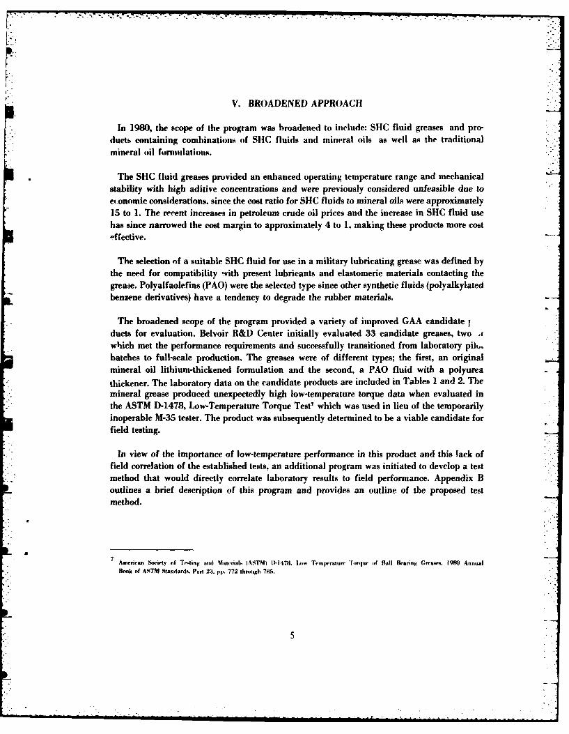
In 1980, the scope of the program was broadened to include: SHC fluid greases and pro-ducts containing combinations of SHC fluids and mineral oils as well as the traditionalmineral oil formulations.
The SHC fluid greases provided an enhanced operating temperature range and mechanicalstability with high aditive concentrations and were previously considered unfeasible due toeconomic considerations, since the cost ratio for SHC fluids to mineral oils were approximately15 to 1. The recent increases in petroleum crude oil prices and the increase in SHC fluid usehas since narrowed the cost margin to approximately 4 to 1, making these products more cost4fective.
The selection of a suitable SHC fluid for use in a military lubricating grease was defined bythe need for compatibility with present lubricants and elastomeric materials contacting thegrease. Polyalfaolefins (PAO) were the selected type since other synthetic fluids (polyalkylatedbenzene derivatives) have a tendency to degrade the rubber materials.
The broadened scope of the program provided a variety of improved GAA candidate 1ducts for evaluation. Belvoir R&D Center initially evaluated 33 candidate greases, two ,which met the performance requirements and successfully transitioned from laboratory pit,.batches to full-scale production. The greases were of different types; the first, an original
mineral oil lithium-thickened formulation and the second, a PAO fluid with a polyurea
thickener. The laboratory data on the candidate products are included in Tables 1 and 2. Themineral grease produced unexpectedly high low-temperature torque data when evaluated inthe ASTM D-1478, Low-Temperature Torque Test7 which was used in lieu of the temporarilyinoperable M-35 tester. The product was subsequently determined to be a viable candidate forfield testing.
In view of the importance of low-temperature performance in this product and this lack offield correlation of the established tests, an additional program was initiated to develop a testmethod that would directly correlate laboratory results to field performance. Appendix Boutlines a brief description of this program and provides an outline of the proposed testmethod.
American Society of Testing and Materials (ASTM) D-1478. IMw 'nemperature Torque of Ball Hearing Greas, 1980 AnnualBmk of ASTM StandardA. Part 23. pp. 772 through 785.
S.
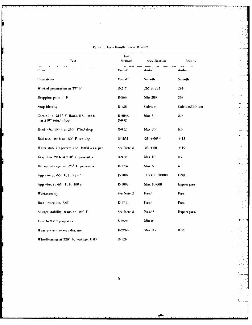
Table I. 'ests Results. Code ME-002
TestTest Method Specification ResuhLs
Color Visual2 Amber Amber
Consistency Visual 2 Snoothi Smooth
Worked penetration at 770 F D-217 265 to 295 284
Dropping point, 0 F )-566 Min 280 368
Soap identity I)-28 Caleium Calcium/Lithium
Corr, Cu at 2120 F, Bomb OX. 10) h 1)-4048. Max 5 2.0
at 2100 Fin. 2 drop [D-942
Bomd4 )x, 4)O h at 210' Fi'. drop 1-942 Max 20' 6.0
LRoll test. 100 h at 150' F pen chg 1-1831 -251+60' + 15
Water stab. 10 percent add. ltX)M stks. pen See Nete 2 -25/+60 + 19
Evap lss. 22 h at 2100 F. percent w D)-972 Max 10 2.7
Oil sep. storage. at 1250 F. percent w I)-1742 Max 6 4.3
App vise at -65' F. P. 25 D" I)-1092 1150)0 to 20000 DNR
App visc, at -650 F, P. 104 sH D-1092 Max 10.000 Expect pass
Workmansh ip See Note 2 Pass' Pass
Rust protection. 4ST D-1i743 Pass' Pass
Storage stability. 6 mo at 4())0 F See Noto 2 Pass' 2 Expect pass
Four ball EP properties D-2596 Min 8'
Wear preventive scar dia. mm D-2266 Max (.7' 0.36
Wheelbearing at 220' F. leakage. (;IS D-1263
L
6
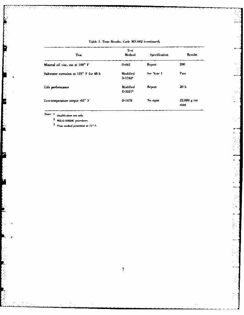
TleIi 1. Tests UCKulls, (AxIe NI l&I)2 0-fonlinuaeoJ)
TIestTest Methimd Specifiration Results
Mineral oil vise, sus at 1000 F ~ D-445 Rvcomrl 200
Saltwater corrosion at 125' F for 48 It Modified See Note I IPa*?iS D- 17432
Lie perfonnance Modified Report 20 hD-3527'
Low-temperature torque -650 F D- 1478 No rqmt 22,000 g cmstart
Not"o: ' Qualification test onty.
2 MIL-G-10924C procedurma
3From worked pentration at 770 F.*
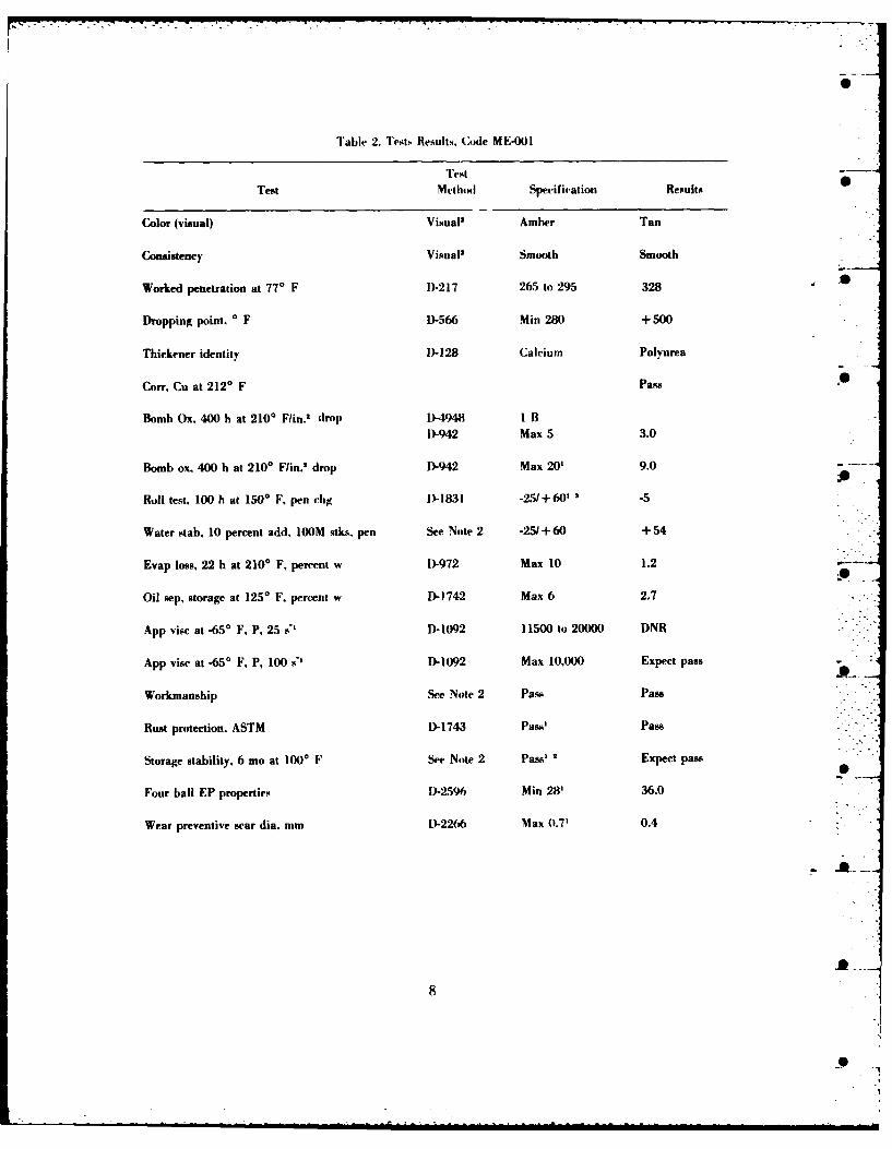
Table 2. Tests Results, Code ME4001
TestTest Methodl Specification Results
Color (visual) Visual' Amber Tan
Consistency Visual2 Smooth Smooth
Worked penetration at 770 F D)-217 265 to 295 3280
Dropping point. 0 F D-566 Min 280 +500
Thickener identity D)-128 Calcium Polyurea
Con., Cu at 2120 IF Pass
Bomb Ox. 400 h at 2100 F/in.' drop D1-4948 IlBD)-942 Max 5 3.0
Bomb ox, 400 h at 2100 F/in.' drop D-942 Max 20' 9.0-
Roll test. 100 h at 1500 FK pen chg D)- Ia3l -25 + 60' '-5
Water stab, 10 percent add, 100M stks, pen See Note 2 -25/ +60 + 54
Evap loss, 22 It at 2100 F, percent w D-972 Max 10 1.2
Oil sep. storage at 1250 F, percent w -1742 Max 6 2.7
App vise at -65' F, P, 25 D1-1092 11500 to 20000 DNR
App visc at -65' F, P, 100 D1-1092 Max 10,000 Expect pass
Workmanship See Note 2 Paso Pass
Rust protection, ASTM D-1743 Pass' Pass
Storage stability, 6 mo at 1000 F See Note 2 Pass'' Expect pass
Four ball EP properties D-2596 Min 28' 36.0
Wear preventive scar dia. mm D-2266 Max 0.7' 0.4
L-
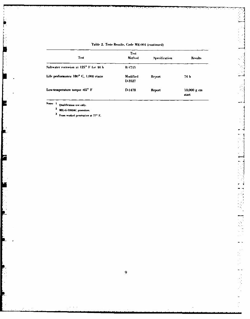
Table 2. Tests Results. Codle ME-4X)l (einitintted)
Test Methodl Specification Results
LWe perfonnanee 180* C, 1.000O rlmin Modified Report 74 Ib
D-3527
Low-temperature torque -65* F D-1478 Report 10,000 g cmtstart
Notes.: IQualification t~ only.
2 NIL-,10924nC proed~ure.
3From worked p..nctratin at 77* F.
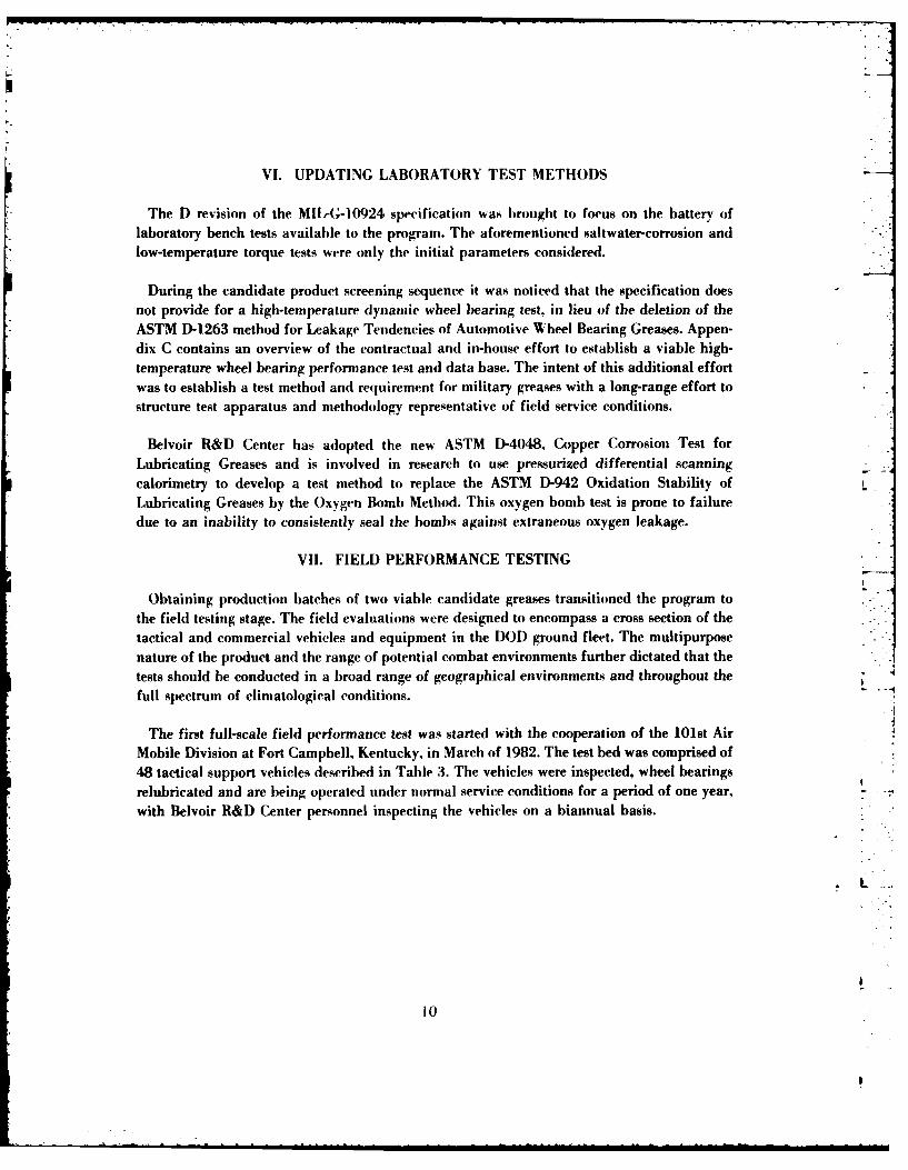
VI. UPDATING LABORATORY TEST METHODS
The D revision of the MIl-G-10924 specification was brought to focus on the battery oflaboratory bench tests available to the program. The aforementioned saltwater-corrosion andlow-temperature torque tests were only the initial parameters considered.
During the candidate product screening sequence it was noticed that the specification doesnot provide for a high-temperature dynamic wheel bearing test, in lieu of the deletion of theASTM D-1263 method for Leakage Tendencies of Automotive Wheel Bearing Greases. Appen-dix C contains an overview of the contractual and in-house effort to establish a viable high-temperature wheel bearing performance test and data base. The intent of this additional effortwas to establish a test method and requirement for military greases with a long-range effort tostructure test apparatus and methodology representative of field service conditions.
Belvoir R&D Center has adopted the new ASTM D-4048, Copper Corrosion Test forLubricating Greases and is involved in research to use pressurized differential scanning -
calorimetry to develop a test method to replace the ASTM D-942 Oxidation Stability ofLubricating Greases by the Oxygen Bomb Method. This oxygen bomb test is prone to failuredue to an inability to consistently seal the bombs against extraneous oxygen leakage.
VII. FIELD PERFORMANCE TESTING
Obtaining production batches of two viable candidate greases transitioned the program to
the field testing stage. The field evaluations were designed to encompass a cross section of thetactical and commercial vehicles and equipment in the DOD ground fleet. The multipurposenature of the product and the range of potential combat environments further dictated that thetests should be conducted in a broad range of geographical environments and throughout thefull spectrum of climatological conditions.
The first full-scale field performance test was started with the cooperation of the 101st Air
Mobile Division at Fort Campbell, Kentucky, in March of 1982. The test bed was comprised of48 tactical support vehicles described in Table 3. The vehicles were inspected, wheel bearingsrelubricated and are being operated under normal service conditions for a period of one year,with Belvoir R&D Center personnel inspecting the vehicles on a biannual basis.
10
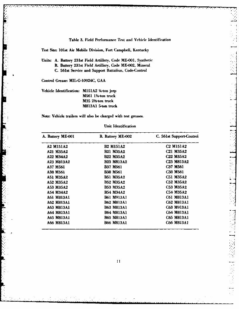
Table 3. Field Performiance Test and Vehicle Identification
Test Site: 101st Air Mobile Division, Fort Campbell, Kentucky
Units: A. Battery 2318t Field Artillery, Code ME-0O1, SyntheticB. Battery 231st Field Artillery, Code ME-002, Mineral
C. 561st Service and Support Battalion, Code-Control
Control Grease: MI-G-10924C, GAA
Vehicle Identification: M151A2 Y-ton jeepM561 1 4-ton truckM35 2 -ton truckM813A1 5-ton truck
* Note: Vehicle trailers will also be charged with test greases.
Unit Identification
A. Battery ME-001 B. Battery ME-002 C. 561st Support-Control
A2 M151A2 B2 M15IA2 C2 M151A2A21 M35A2 B21 M35A2 C21 M35A2A22 M34A2 B22 M35A2 C22 M35A2A23 M813A2 B23 M813A2 C23 M813A2A37 M561 B37 M561 C37 M561A38 M561 B38 M561 C38 M561A51 M35A2 B51 M35A2 C51 M35A2A52 M35A2 B52 M35A2 C52 M35A2A53 M35A2 B53 M35A2 C53 M35A2A54 M34A2 B54 M34A2 C54 M35A2A61 M813AI B61 M913AI C61 M813AI
*A62 M813A1. B62 M813AI C62 M813AIA63 M813A1. B63 M813AI C63 M913AIA64 M813AI B64 M813A1. C64 M813AIA65 M813AI B65 M813AI C65 M813A1IA66 M813AI B66 M813AI C66 M813AI
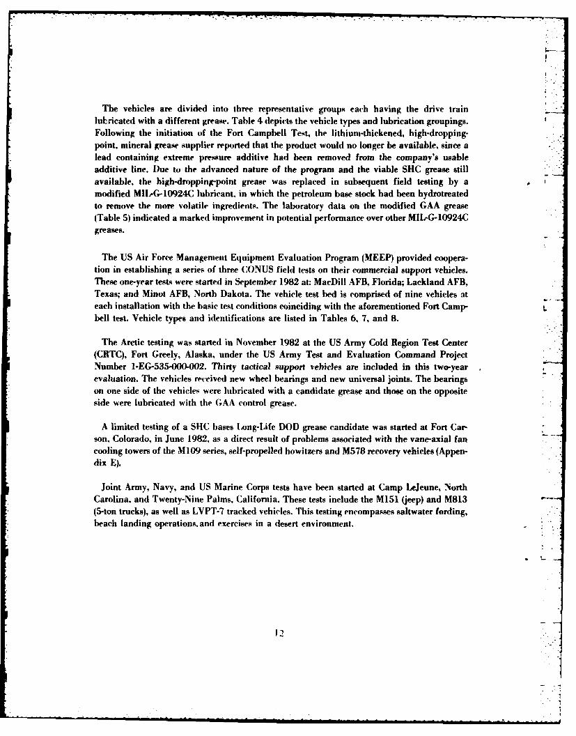
The vehicles are divided into three representative groups each having the drive trainlubricated with a different grease. Table 4 depicts the vehicle types and lubrication groupings.Following the initiation of the Fort Campbell Test, the lithium-thickened, high-dropping-point, mineral grease supplier reported that the product would no longer be available, since alead containing extreme pressure additive had been removed from the company's usableadditive line. Due to the advanced nature of the program and the viable SHC grease stillavailable, the high-dropping-point grease was replaced in subsequent field testing by amodified MIL-G-10924C lubricant, in which the petroleum base stock had been hydrotreatedto remove the more volatile ingredients. The laboratory data on the modified GAA grease(Table 5) indicated a marked improvement in potential performance over other MIL-G-10924Cgreases.
The US Air Force Management Equipment Evaluation Program (MEEP) provided coopera-tion in establishing a series of three CONUS field tests on their commercial support vehicles.These one-year tests were started in September 1982 at: MacDill AFB, Florida; Lackland AFB,Texas; and Minot AFB, North Dakota. The vehicle test bed is comprised of nine vehicles ateach installation with the basic test conditions coinciding with the aforementioned Fort Camp- Lbell test. Vehicle types and identifications are listed in Tables 6, 7, and 8.
The Arctic testing was started in November 1982 at the US Army Cold Region Test Center(CRTC), Fort Greely, Alaska, under the US Army Test and Evaluation Command ProjectNumber 1-EG-535-000-002. Thirty tactical support vehicles are included in this two-yearevaluation. The vehicles received new wheel bearings and new universal joints. The bearingson one side of the vehicles were lubricated with a candidate grease and those on the oppositeside were lubricated with the GAA control grease.
A limited testing of a SHC bases Long-Life DOD grease candidate was started at Fort Car-son, Colorado, in June 1982, as a direct result of problems associated with the vane-axial fancooling towers of the M109 series, self-propelled howitzers and M578 recovery vehicles (Appen-dix E).
Joint Army, Navy, and US Marine Corps tests have been started at Camp LeJeune, NorthCarolina, and Twenty-Nine Palms, California. These tests include the M151 (jeep) and M813(5-ton trucks), as well as LVPT-7 tracked vehicles. This testing encompasses saltwater fording,beach landing operations. and exercises in a desert environment.
12
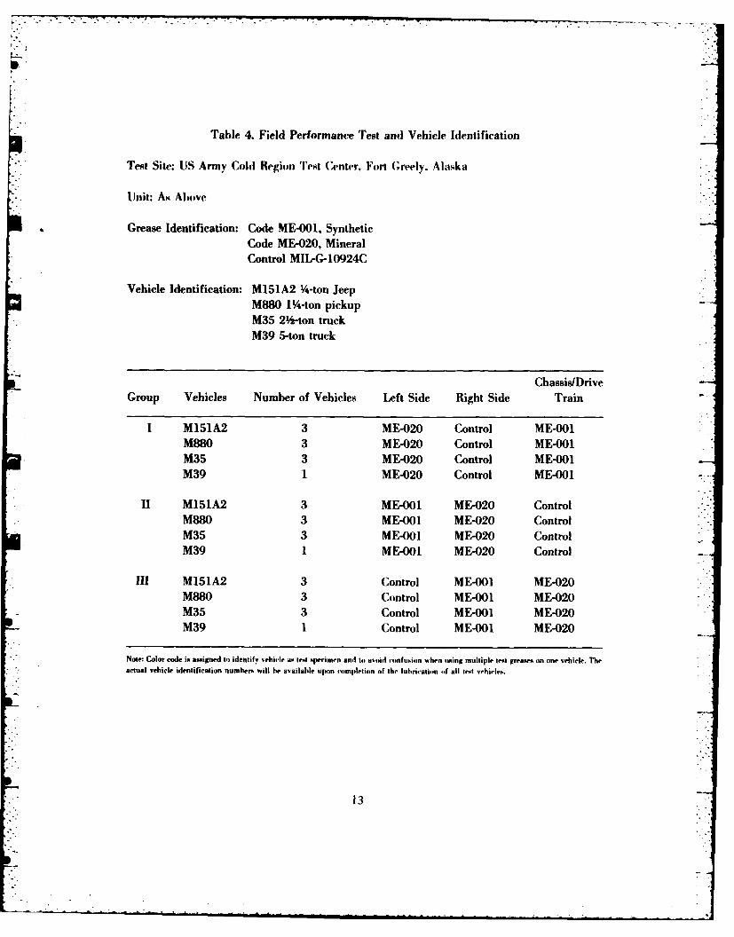
Table 4. Field Performance Test and Vehicle Identification
Test Site: US Army Cold Region Test ('enter. Fort (;reely, Alaska
Unit: As Above
Grease Identification: Code ME-OO1, SyntheticCode ME-020, MineralControl MIIPG-10924C
Vehicle Identification: M151A2 Y-ton JeepM880 P14-ton pickupM35 2%'-ton truckM39 5-ton truck
Chassis/DriveGroup Vehicles Number of Vehicles Left Side Right Side Train
I M151A2 3 ME-020 Control ME-001M880 3 ME-020 Control ME-001M35 3 ME-020 Control ME-001M39 1 ME-020 Control ME-001-
Ii M151A2 3 ME-001 ME-020 ControlM880 3 ME-001 ME-020 ControlM35 3 ME-00i ME-020 ControlM39 I ME-001 ME-020 Control
III M151A2 3 Control ME-001 ME-020M880 3 Control ME-00i ME-020M35 3 Control ME-0bi ME-020M39 I Control ME-00i ME-020
Note: Color code is assigned to idenstify vehirle as test specimen and to avoid ronfosiimn %hen using multiple test greases on one vehicle. Theactual vehicle identification numbers will he available upon completion of the lubrication of all test vehicles.
13
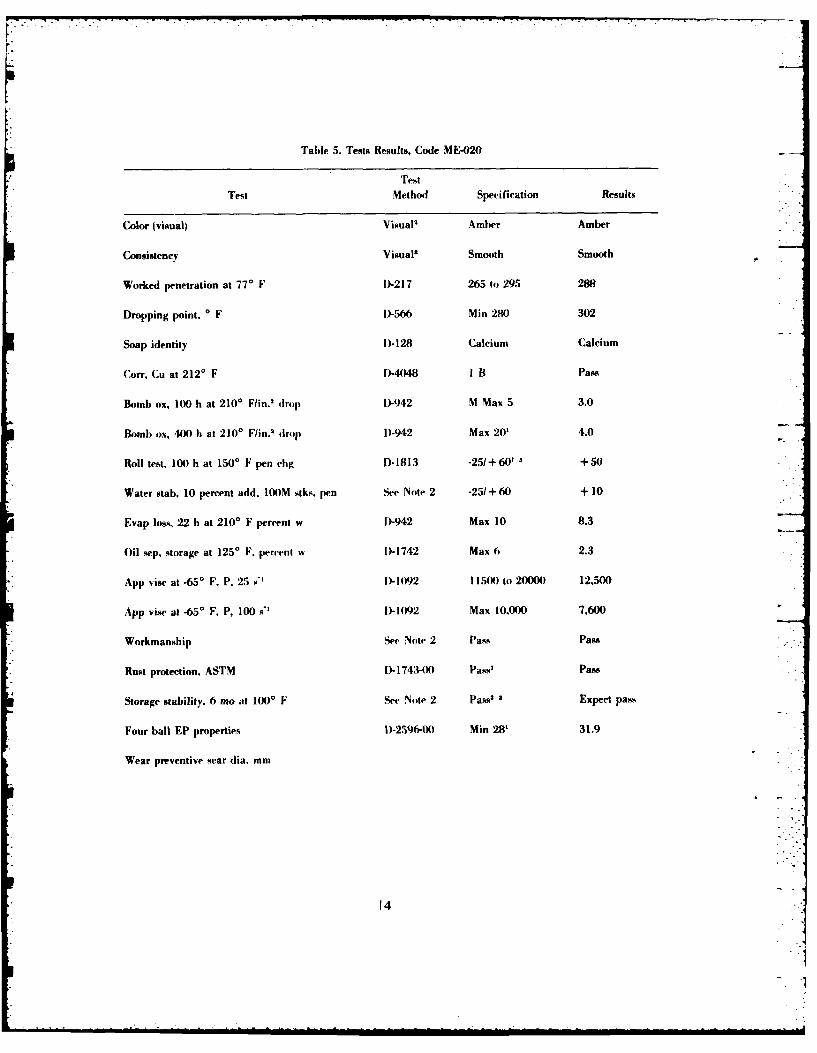
Table 5. Tests Results, Code ME-020
Test
Test Method Specification Results
Color (visual) Visual' Amber Amber
Consistency Visual' Smooth Smooth
Worked penetration at 770 F 0)-21 7 265 tw 29.5 288
Dropping point. * F D-566 Min 280) 302
Soap identity D)-128 Calcium Calcium
Coff. Cu at 2120 F f"4)48 I B Pass
Bomb ox, 10M h at 2100 F/in.2 drop D-942 M Max 5 3.0
Bomb ox, 400 h at 2100 F/in.2 drop D)-942 Max 20' 4.0
Roll test, 100 h at 150' F pen dig D*1813 -25/ +60' 3+50
Water stab, 10 percent add, 100M stks. pen See Note 2 -25/ +60 + 10
Evap loss, 22 h at 2100 F percent w D-942 Max 10 8.3
Oil sep. storage at 1250 F. percent w D)-1742 Max 6 2.3
App vise at .650 F. P. 25 s" D-1092 115 0) to 20000 12,500
App, vise at -650 F. P, 100 W' D- 1092 Max 10,000 7,600
Workmanship Set- Note 2 Pass Pass
Rust protection. ASTM D- 1743-0) Pass' Pass
Storage stability. 6 mo at 1000 F See Note 2 Pass1 ' Expect pass
Four ball EP properties D-2596-0) Min 28' 31.9
Wear preventive scar dia. mm
14
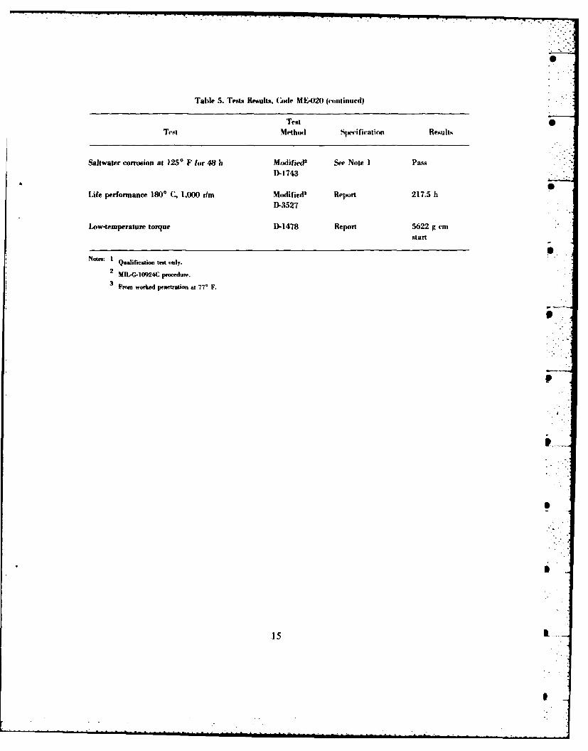
Table 5. Tests Results. COde MEI-020 (4coutinued)
TestTest Methodl Specification Results
Saltwater corrosion at 1250 F for 48 h Modified2 See Note 1 Pass
D)-1743
Life performance 1800 C, 1,000 r/m Modified' Report 217.5 ht
D-3527
Low-temperature torque D-1478 Report 5622 g emistart
Notes: I Qualification teat only.
2MttA-10924C procedure.
From worked penetration at 77* F.
15 Il
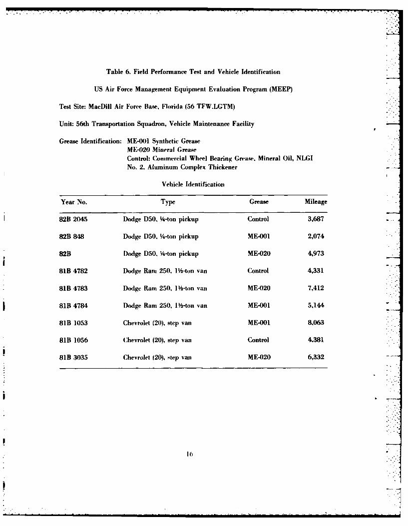
Table 6. Field Performance Test and Vehicle Identification
US Air Force Management Equipment Evaluation Program (MEEP)
Test Site: MacDill Air Force Base, Florida (56 TFW.LGTM)
Unit: 56th Transportation Squadron, Vehicle Maintenance Facility
Grease Identification: ME-001 Synthetic GreaseME-020 Mineral GreaseControl: Commercial Wheel Bearing Grease, Mineral Oil, NLGINo. 2, Aluminum Complex Thickener
Vehicle Identification
Year No. Type Grease Mileage
82B 2045 Dodge D50, 4-ton pickup Control 3,687•
82B 848 Dodge D50, Y4-ton pickup ME-001 2,074
82B Dodge D50, V4-ton pickup ME-020 4,973
81B 4782 Dodge Ram 250, 1 -ton van Control 4,331
81B 4783 Dodge Ram 250, 1 -ton van ME-020 7,412
81B 4784 Dodge Ram 250, 1 -ton van ME-001 5,144
81B 1053 Chevrolet (20), step van ME-001 8,063
81B 1056 Chevrolet (20), step van Control 4,381
81B 3035 Chevrolet (20), step van ME-020 6,332
16
I ' "
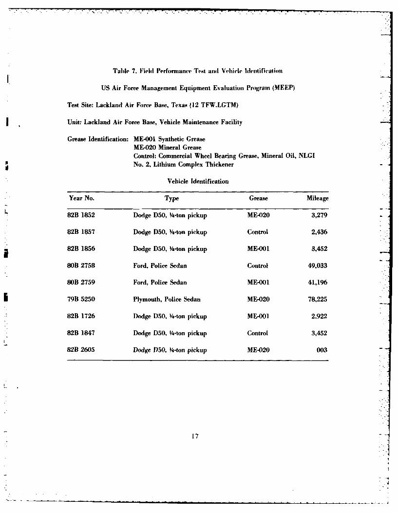
Table 7. Field Performnc~e TF4st andi Vehicle IdenItification
US Air Force Management Equipment Evaluation Progranm (MEEP)
Test Site: Lackland Air Force Base, Texas (12 TFW.LGTM)
Unit: Lacklarad Air Force Base, Vehicle Maintenance Facility
Grease Identification: ME-001 Synthetic GreaseME-020 Mineral GreaseControl: Commercial Wheel Bearing Grease, Mineral Oil, NLGINo. 2, Lithium Complex Thickener
Vehicle Identification
Year No. Type Grease Mileage
L82B 1852 Dodge DSO, 4-ton pickup ME-020 3,279
82B 1857 Dodge D50, 4-ton pickup Control 2,436
82B 1856 Dodge D50, A-ton pickup ME-001 3,452
80B 2758 Ford, Police Sedan Control 49,033
80B 2759 Ford, Police Sedan ME-001 41,196
79B 5250 Plymouth, Police Sedan ME-020 78,225
82B 1726 Dodge D50, Y-ton pickup ME-001 2,922
82B 1847 Dodge D50, Y-ton pickup Control 3,452
82B 2605 Dodge D50, 4-ton pickup ME-020 003
17
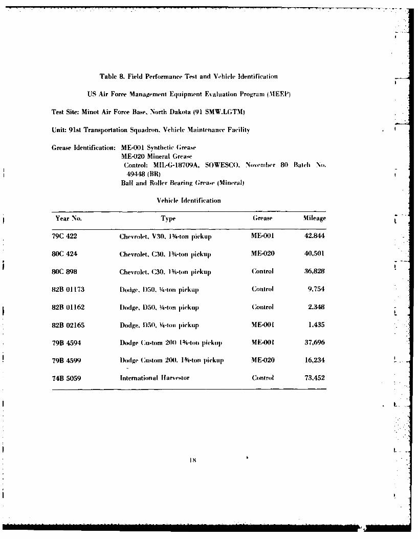
Table 8. Field Performance Test and Vehicle Identification
US Air Force Management Equipment Evaluation Program (NMEEP)
Test Site: Minot Air Force Base. North Dakota (91 SMW.LGTM)
Unit: 91st Transportation Squadron, Vehicle Maintenance Facility
Grease Identification: ME-001 Synthetic G;reaseME-020 Mineral GreaseControl: MIL-G-18709A, SOWESCO. November 80 Batch No.49448 (BR)
Ball and Roller Bearing Grease (Mineral)
Vehicle Identification
pYear No. Type Grease Mileage
79C 422 Chevrolet, V30. 1 4-ton pickup ME-001 42.844
80C 424 Chevrolet, C30, 1 -ton pickup ME-020 40,501
80C 898 Chevrolet. C30. 1 4-ton pickup Control 36,828
82B 01173 D~odge. 1)50. V4-ton pickup Control 9,754
82B 0 1162 Dodge. 1)50, 1/-ton pickup Control 2.348
82B 02165 Dodge. D)5(0, V4-ton pickup M E-0I 1,435
*79B 4594 Dodge Custom 20(0 1 /-ton pickup MIE-001 37,696
79B 4599 Dodge Custom 200. 1 /-ton pickup ME-020 16,234
*74B 5059 International Hfarvestor Control 73,452
181
Artillery testing is being conducted at the US Army Artillery School. Fort Sill. Oklahoma.This testing will include 18 self-propelled (MI09) and 18 towed artillery (MI02) guns. The
testing will be conducted primarily on the road wheel hearings, since all (MI09) self-propelledhowitzers were converted from oil to grease lubrication in 1983. Select artillery pieces will also
be designated to receive complete cleaning and relubrication of all GAA designatedcomponents.
The conversion from oil to grease of the M109 self-propelled howitzer road wheel bearings isthe fifth major conversion that has been accomplished as a result of the problems observed inthe M60 and M48 tanks in the 1960. The others converted are the Ml13 Armored PersonnelCarrier and Ml 10 series self-propelled howitzer. A number oi existing and new military equip-ment continues to use the oil lubrication theory. Some of the major vehicles and equipmentusing oil are: the M-1 (Abrams Tank), M-2 (Bradley Fighting Vehicle), Multiple Launch RocketSystem, USMC LVPT-7 (Amphibious Landing Vehicle) and M915 series trucks.
Commercial manufacturers of Department of Defense vehicles and equipment continue topromote oil lubrication in new military equipment as is the status quo for commercial equip- -
ment. However, civilian operation modes and repair criteria differ vastly from military re-
quirements, in that military vehicles and equipment are often prepositioned in storage andmay not be operated on a regular basis. This tactical combat equipment requires the capabilityof immediate mobilization in the event of hostile actions, with repair-to-track relatedassemblies being time consuming and hazardous in a hostile environment.
The loss or leakage of one oil seal can immobilize equipment permanently in a threat situa-tion, while the semi-fluid consistency of grease will allow for continued lubrication and com-
bat operational effectiveness.
Tropical test sites are being established in conjunction with the US Army Tropical TestCenter, Fort Clayton, Panama, and the 84th Combat Heavy Engineer Battalion, Fort Shafter,Hawaii. The tests at both sites will be started in early 1984.
Fording (water immersion) testing has been validated as a critical concern in the areas of
water washout and, also, the ability of the lubricant to inhibit corrosion. Fresh and saltwaterfording subtests have been established within the tests at Camp LeJuene, North Carolina; FortClayton, Panama; and Fort Greely, Alaska.
19
2..
VIII. INITIAL RESULTS
The scheduled September 1982 monitoring and inspection of the test vehicles at Fo t'amp-bell, Kentucky, indicated that the mineral oil lubricating greases were being washed off thewheel bearings in the vehicles having MIL-L-2105 Gear Oil Grade 80W-90 lubricated dif-ferentials. The mineral oil greases were completely removed in as little as 200 to 300 nileaving the bearing coated with 80W-90 in periods of inactivity. The PAO fluid polyureagrease has remained intact. However, the 80W-90 washout factor was not included orignally asa consideration in the program. No mechanical failures were observed on any of the testvehicles.
The one-year scheduled completion of the test was achieved and no failures were observed onany test vehicles. This prompted Belvoir R&D Center to solicit the cooperation of Fort Camp- O
bell personel in continuing the test cycle for an additional year in order to evaluate thefeasibility of extending the lubrication interval and examining more thoroughly the gear oilwashout problem as described in Appendix E. Fort Campbell personnel agreed to the extentionand have begun the second test sequence. The test cycle will be started by replacing all bearing-seals in the test vehicles and providing Belvoir R&D Center with the old parts and samples ofthe test greases from each bearing gear oil samples from the rear differentials. The sampleswill be used in the laboratory evaluation of grease breakdown and forthcoming gear oil con-tamination analysis. The seals will be inspected to determine if they are failing.
The Air Force commercial support vehicle tests were monitored at MacDill AFB, Florida, _
and Lackland AFB, Texas, after 6 mo of normal operation and no mechanical failures wereobserved. Several vehicles required additional lubrication, although the tests are progressingtoward the one year completion date. Samples of the test greases were obtained for laboratoryevaluation. The third Air Force test at Minot AFB, North Dakota, will be monitored and in-spected by base personnel in July 1983 after 8 mo of high mileage operation. Samples of thelubricants from this test bed are being forwarded to Belvoir R&D Center for inclusion in thelaboratory grease analysis.
The arctic test at Fort Greely, Alaska, resulted in no cold weather performance problems ormechanical failure in the test vehicles. The 6-mo inspection and grease sampling have beencompleted, and samples of the greases and maintenance observations are being forwarded tothe Belvoir R&D Center.
The limited self-propelled howitzer testing at Fort Carson, Colorado, has proved successfulin eliminating cooling fan failures in its first year of operation. Appendix E provides a moredetailed report of this project and outlines further testing being pursued, including sugges-tions, Modification Work Orders. and expansion of the test to include MIIO and M578vehicles.
20
.0 i
IX. CONCLUSIONS
On the basis of test data, economic considerations and the long-range program direction, thefollowing conclusions were made:
The MIL-G-10924D specification was drafted around the performance requirements of the .improved MIL-G-10924C mineral oil grease (Table 1). The specification was circulatedthroughout the DOD for comments and was published in July 1983. The mineral grease was 0selected as the MIl-G-10924D product on the basis of cost effectiveness and insured com-patibility with the present lubricant and elastomer materials. Although having a superiortemperature range, the synthetic hydrocarbon fluid (PAO) grease is approximately four timesthe cost of the mineral greases. The PAO grease is a candidate product in the DOD Long-LifeGrease Program currently in progress, and a complete change over to a grease of this type in Sthe future is a prominent possibility. The transition of the entire DOD ground fleet to a pro-duct of this type requires extensive research and the data is to be supplied by the ongoing fieldperformance evaluations. A purchase description has been drafted around the performance re-quirements of the PAO fluid grease enabling its procurement and use in specific applicationswhere an extended lubrication cycle or a 3500 F operating capacity is required. A high Pdropping point mineral oil grease patterned around the original mineral GAA candidate is inthe final formulation stages and may be available in FY84 through the first amendment of theMIL-G-10924D specification.
21
now.1
APPENDIX A
SALTWATER RUST PROTECTION METHOD
The following is a test method for determining the corrosion preventive properties oflubricating greases in tapered roller hearings in the simulated service conditions oftemperature and humidity from being in contact with water.
A-1. Scope. This method tests the corrosion preventive characteristics of lubricating greasesin the presence of water. It is based on improvements to the ASTM Method D-1743 which is
derived from the Coordinating Research Council (CRC) technique I-41.
A-2. Applicable Documents. ASTM Standards: D-484 Specification for Hydrocarbon DryCleaning Solvent; D-1743 Corrosion Preventive Properties of Lubricating Greases; D-3527High Temperature Life Performance of Lubricating Greases; ASTM D-665, Rust PreventiveCharacteristics of Steam Turbine Oil in the Presence of Water, Paragraph 6, Procedurf B forSynthetic Seawater, 1980 Annual Book of ASTM Standards, Part 23, pp. 337: FederalSpecification P-D-680 and 3, Type l-Drycleaning Solvent.
A-3. Summary of Method. Clean new tapered roller bearings are lubricated with the testgrease and run-in under a thrust load of 4 kg for 60 s. The bearings are then covered withwater for 60 s with a portion of the water allowed to remain in the test jar while it is in an ovenfor 3 h at 520 + 10 C (125' F). At the completion of the test the bearing cup races are ratedfor corrosion.
A-4. Significance. This method differentiates the relative rust preventive capabilitiesof lubricating greases under the conditions of this test. The test is conducted with seawaterwhich expands the scope of the investigation.
A-5. Apparatus and Materials. Bearings cone and cup bearing assembly LM11949-LM11910. Solvent rinse solution as described in D-1743. Stoddard or drycleaning solvent.Plastic test jar, 16 oz, 100 cc syringe and 6-in. needle, and the bearing packer described inD-3527 or D-1743. Spatula with square end and a blade width of approximately V4-in. and 1to 2 in. long. The bearing holders and thrust loading apparatus are commercially available
through manifacturers of petroleum laboratory test apparatus. Synthetie seawater meets the LAmerican S,,iety of Testing and Materials Standard I)- 141-52. Formula A. Table 1,Section 4.
22I

A-6. Standardization of the Thrust Loader. Place the thrust loader vertically in avise by gripping the shank. Place a total of 3 :L 0.1 kg on the stopper and mark the shaftwhere it and the square-holed shaft meet. The two shallowest channels of the shaft may heprinted or marked in some way to readily indicate the amount of compression required toduplicate the 3 - 0.1 kg load.
A-7. Procedure. Should a mechanical bearing packer, as described in ASTM MethodD-3527 not be available, go to the next paragraph of this procedure. After packing the testgrease into the bearing remove the packer body by lifting it over the plunger, then slide theplunger off to avoid pulling grease from the bearing. Leave the bearing on the packer spindleand use a small spatula to remove the excess grease from the cone front face. Next, place thespatula's edge of the cage and cone front face and move the spatula to remove the excessgrease. Place the spatula squarely on the cup back face and the square end of the spatulaagainst the cage. Rotate again to remove the excess grease. After the removal of the excessgrease, the remaining lubricant should be level and uniform. Wipe away any excess greasefrom the outside of the cup and place a plastic bearing holder over the bearing. Remove thebearing from the packer spindle and wipe away any grease from within the bore. Avoidrotating the bearing because the procedure of removing the excess grease is intended to insurethat a consistent volume of grease is put in each bearing. Again, with the spatula, remove allgrease from the cone back face. Then, placing the spatula's square end against the side of thecone back face and on top of the cage end, remove the excess grease. Place the spatula edgesquarely on the cup front face and the spatula end against the cage, and remove the excessgrease from this region of the bearing. The procedure of removing the grease is intended to in-sure that the same volume of grease is used each time. From this point on, the occurrence ofrotation is not critical, but the cup and cone must not be permitted to separate.
If only the bearing packer described in the ASTM D-1743 method is available, followthese directions. Pack the bearing with the test grease. While holding the bearing by the bore,remove the excess grease from the cone front face and the other regions as described in theprevious paragraph. Place a plastic bearing holder over the bearing and remove the grease
" from the cone back face as was described for the ASTM D-3527 bearing packer.
To complete the mounting of the bearing, place a large diameter flange into the coneback face end of the bore, and place a small diameter flange into the bore's other end. Next,place the assembled bearing's large flange down on a 1-kg weight. Insert and tighten the con-necting screw. Place an inverted plastic jar over the assembly, and slide the assembly to theedge of the flat surface. Allow the weight to come onto your fingers, then raise it until theO-ring contacts the bottom of the jar. Maintaining slight pressure, invert the assembly and jar,and place on a flat surface.
23
A-8. Run-In Procedure. Place the calibrated thrust loader in a drill press or laboratorymotor which is on a vertically movable platform such as a ring stand. Position the bearingassembly in the plastic jar under the thrust loader, and lower it until the rubber stopper comesinto contact with the weight. Rotate the motor by hand to observe that the rubber stopper is notout of alignment with the center of the weight and likely to produce vibration during Run-In.Next, while observing the calibration marking on the thrust loader shaft, compress the spring_-until the calibration mark and the square-holed piece align. Then, lock the drill press or motorwhich places the desired thrust loading on the bearing. Run-In the bearing for 60 * 3 s. At theend of the Run-In time, release the thrust loader, and allow the bearing and weight to coast to astop. Bearing assembly is not to be handled so as to be subjected to such tough handling thatthe cone and cup would become even momentarily separated.
Within 1 h of the Run-In begin a 60 : 3 s time period. Within the first 3 s, pour intothe plastic jar containing the bearing assembly, 100 :L 2 cc of water. After 50 s into the timeperiod, begin to remove 70 4- 2 cc of water from the vertical hole in the plastic bearing holderwith the 100-cc syringe. Complete the removal of the water within the 60 + 3-s time period.Water may remain on the top of the weight without adverse affect. Tightly place the lid on thejar, and begin the 3-h :. 5-min test period in a 51.70 C, (1250 F) oven.
At the completion of the test period, open the jar, and pour off the water. Invert the jar,and place the assembly on a flat surface; then, remove the jar. Lift off the bearing holder, andremove the cup. Wipe the cup free of grease with a clean, dry rag, and rate the inner race of the -
cup via the method described in the ASTM D-1743 procedure.
Note: Initial saltwater rust protection testing of candidate improved MIL-G-10924greases were conducted for 48 4E 1 h and yielded results clearly differentiating betweenlubricating greases having superior saltwater corrosion inhibition properties, although the --results of this test phase could not be rated adequately by the standard ASTM D-1743 ratingcriteria. The difficulty in establishing a quantifiable rating standard prompted the reductionin elevated temperature test time from 48 4. 1.0 h to 3 h + 5 min in order to use the ASTMD-1743 method rating scheme as a model for indication of failure.
The test method will continue to be revised in conjuntion with the ongoing field perfor-mance evaluations in order to determine an adequate saltwater corrosion requirement. In-vestigations are also in progress to develop more quantifiable rating criteria.
24
APPENDIX B
LOW-TEMPERATURE TORQUE TESTING
OF AUTOMOTIVE WHEEL BEARING GREASE
The following is a test method for determining the low-temperature functionability oflubricating greases in tapered roller bearings in the simulated service conditions of extendedexposure to conditions of arctic temperature and humidity. This method is to be used in con-junction with the Belvoir R&D Center M-35, 2 -ton truck apparatus to formulate test database composed of low-temperature torque data covering the different size tapered roller bear-ing used in Department of Defense (DOD) tactical and support vehicles and equipment. Thedata base will be correlated to the results torque data observed on actual vehicles tested in en-vironmental chambers and under field service conditions through the use of wheel torque sen-sors. The end result of this method and the low-temperature torque program is intended toviably establish low-temperature grease requirements as a function of starting and runningtorque observable in a field-correlated laboratory bench test.
The initial draft of a proposed US Army test method is adapted from research being con-ducted by the American Society of Testing and Materials (ASTM), "D" Committee, Subcom-mittee G-III-3A on Low-Temperature Torque of Automotive Wheel Bearing Greases.
B-1. Scope. This test method determines the extent to which a grease retards therotation of a spring-loaded automotive front wheel bearing assembly when lubricated with atest grease and subjected to sub-zero temperatures. The method was developed using greasesgiving torques of less than 34 N-m (300 lb-in.) at temperatures from -18' C to -54' C. The testshall be run at 1 rlmin at -540 C.
B-2. Applicable Documents. GM 9078-P, General Motors Engineering Standards,Materials, and Processes, page W-81.301, July 1970, Engineering Staff, General Motors Cor-poration, Warren, Michigan. ASTM D-484, Specification for Hydrocarbon Dry CleaningSolvents; ASTM D-3527, High Temperature Life Performance of Lubricating Greases. FederalSpecification P-D-680 and AM.3, Type Il-Drycleaning Solvent.
B-3. Significance. This method differentiates between wheel bearing greases which arefunctional in military equipment at temperatures down to -540 C.
25
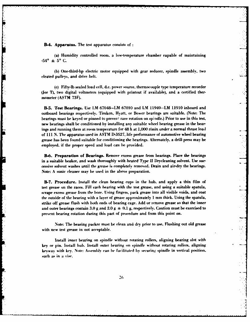
B-4. Apparatus. The test apparatus consists of:
(a) Humidity controlled room, a low-temperature chamber capable of maintaining-540 + 50 C.
(b) One-third-hp electric motor equipped with gear reducer, spindle assembly, twocleated pulleys, and drive belt.
(c) Fifty-lb sealed load cell, d.c. power source, thermocouple type temperature recorder(Jor T), two digital voltmeters (equipped with printout if available), and a certified ther-mometer (ASTM 73F).
B-5. Test Bearings. Use LM 67048-LM 67010 and LM 11949-LM 11910 inboard andoutboard bearings respectively. Timken, Hyatt, or Bower bearings are suitable. (Note: Thebearings must be keyed or pinned to prevent race rotation on spindle.) Prior to use in this test,new bearings shall be conditioned by installing any suitable wheel bearing grease in the bear-ings and running them at room temperature for 48 h at 1,000 r/min under a normal thrust loadof 111 N. The apparatus used in ASTM D-3527, life performance of automotive wheel bearinggrease has been found suitable for conditioning the bearings. Alternately, a drill press may beemployed, if the proper speed and load can be provided.
B-6. Preparation of Bearings. Remove excess grease from bearings. Place the bearingsin a suitable beaker, and wash thoroughly with heated Type 11 Drycleaning solvent. Use sue-cessive solvent washes until the grease is completely removed. Drain and air-dry the bearings.Note: A sonic cleaner may he used in the above preparation.
B-7. Procedure. Install the clean bearing cups in the hub, and apply a thin film oftest grease on the races. Fill each bearing with the test grease, and using a suitable spatula,scrape excess grease from the bore. Using fingers, pack grease into all visible voids, and coatthe outside of the bearing with a layer of grease approximately 1 mm thick. Using the spatula,strike off grease flush with both ends of bearing cage. Add or remove grease so that the innerand outer bearings contain 3.0 g and 2.0 g + 0.1 g, respectively. Caution must be exercised toprevent bearing rotation during this part of procedure and from this point on.
Note: The bearing packer must be clean and dry prior to use. Flushing out old greasewith new test grease in not acceptable.
Install inner bearing on spindle without rotating rollers, aligning bearing slot withkey or pin. Install hub. Install outer bearing on spindle without rotating rollers, aligningkeyway with key. Note: Assevnlv can be facilitated by securing spindle in vertical position.such as in a vise.
26
.i
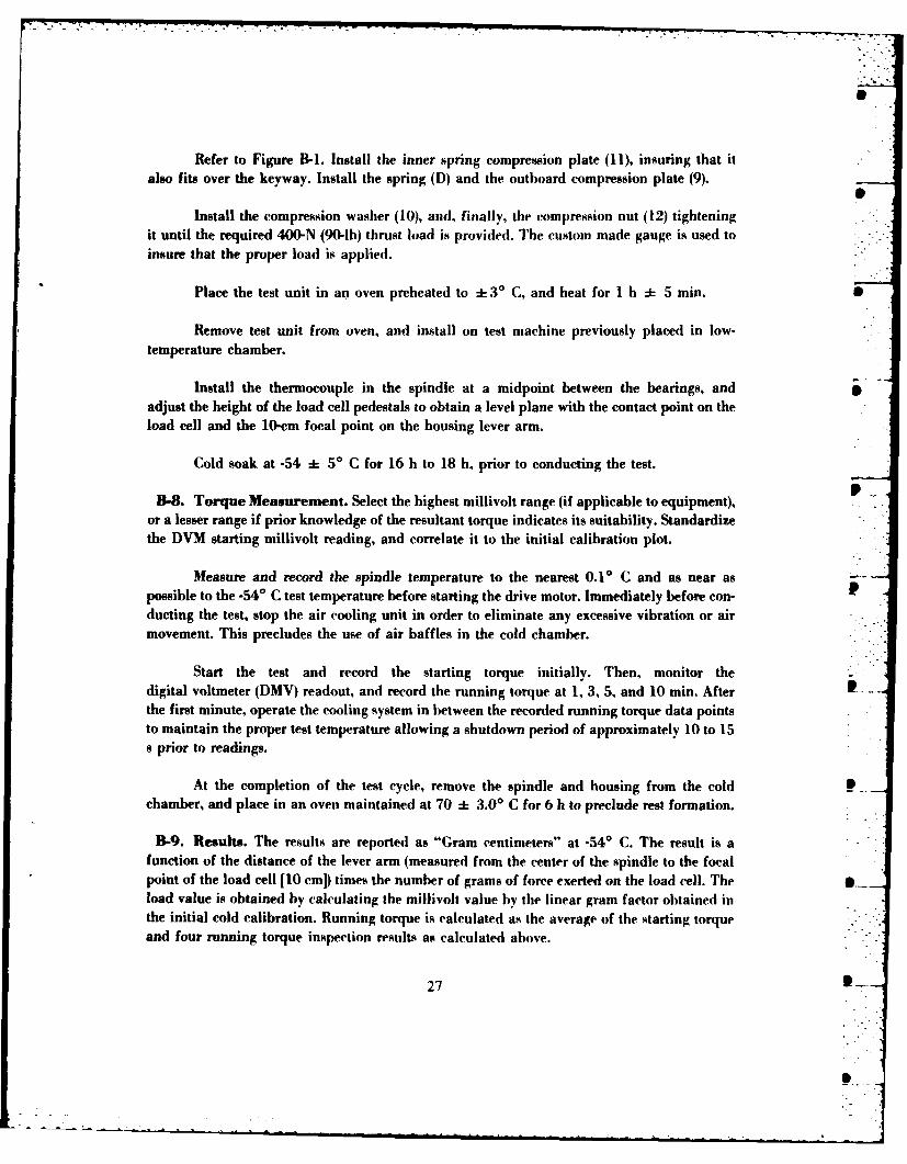
Refer to Figure B-I. Install the inner spring compression plate (11), insuring that italso fits over the keyway. Install the spring (D) and the outboard compression plate (9).
Install the compression washer (10), and, finally, the compression nut (12) tighteningit until the required 400-N (90-1b) thrust load is provided. The custom made gauge is used toinsure that the proper load is applied.
Place the test unit in an oven preheated to -3' C, and heat for I h -5 min.
Remove test unit from oven, and install on test machine previously placed in low-temperature chamber.
Install the thermocouple in the spindle at a midpoint between the bearings, andadjust the height of the load cell pedestals to obtain a level plane with the contact point on theload cell and the 10-cm focal point on the housing lever arm.
Cold soak at -54 * 5* C for 16 h to 18 h, prior to conducting the test.
B-8. Torque Measurement. Select the highest millivolt range (if applicable to equipment),or a lesser range if prior knowledge of the resultant torque indicates its suitability. Standardizethe DVM starting millivolt reading, and correlate it to the initial calibration plot.
Measure and record the spindle temperature to the nearest 0.10 C and as near aspossible to the -540 C test temperature before starting the drive motor. Immediately before con-ducting the test, stop the air cooling unit in order to eliminate any excessive vibration or airmovement. This precludes the use of air baffles in the cold chamber.
Start the test and record the starting torque initially. Then, monitor thedigital voltmeter (DMV) readout, and record the running torque at 1, 3, 5, and 10 min. Afterthe first minute, operate the cooling system in between the recorded running torque data pointsto maintain the proper test temperature allowing a shutdown period of approximately 10 to 15s prior to readings.
At the completion of the test cycle, remove the spindle and housing from the coldchamber, and place in an oven maintained at 70 + 3.00 C for 6 h to preclude rest formation.
B-9. Results. The results are reported as "Gram centimeters" at -54* C. The result is afunction of the distance of the lever arm (measured from the center of the spindle to the focalpoint of the load cell [10 cm]) times the number of grams of force exerted on the load cell. The .load value is obtained by calculating the millivolt value by the linear gram factor obtained inthe initial cold calibration. Running torque is calculated as the average of the starting torqueand four running torque inspection results as calculated above.
27
S -

CI LU
W-C
CV2 Lu r-
C.31
280

B-1O. Calibration. Construct calibration curves of torque as a function of millivoltreadings on DVM. Prior to calibration of the load cells, a DVM will be connected to the loadcell power sources to insure that the input power and output signals of the load cells remainconstant throughout the calibration and operational procedures of the test. A 10-V input to theload cells is used, generally, with cells of this type. However, specification data must be con-suited prior to making the equipment operational. The calibration will be conducted in the
* following manner. Electrically null the load cell and potentiometer of the DVM as close to zeroas possible, and record the DVM readout to a minimum of three decimal places. If required,select a millivolt range on the DVM and record the change in millivolt readout, as known forceis applied to the load cell. Apply several known loads to the load cell in a stepwise fashion,while recording the millivolt changes as a function of the applied torques. Depending on themodel of DVM used, it may be required to calibrate the other millivolt ranges in a similar
, manner until the maximum capacity of the load cell is reached [34 N-m (300 lb in.)]. A re-cording potentiometer (strip chart) may be used in place of the DVM. The accuracy of theequipment should be closely scrutinized prior to use.
B-I1. Cold Calibration. The load cell shall be calibrated at -540 C _+ 0.50 C. Load cellsL with temperature compensation built into the gauge shall be tested at -540 C, also. The cold
calibration is a critical element of the procedure. In the apparatus listing of the method, ahumidity-controlled room and hermetically-sealed load cell is listed, since with small coldchambers the load cells Will be exposed to the immediate atmosphere during calibration loadchanges. This procedure will cause condensation in the test chamber.
The test apparatus should be located in a low humidity, controlled environment toreduce the chance of condensation of moisture in the chamber and subsequent ice crystalliza-tion in the test grease, in order to simulate closely the humidity associated with sub-zerotemperatures. The controlled environment is not a mandatory aspect of the test, although asuitable desiccant should be used in the cold chamber.
Upon completion of the calibration, a plot (load vs. DVM millivolt output) should bedeveloped for each millivolt range, if applicable. Retain these calibration curves for the subse-quent determination of the torque of test greases. If the plots are linear, simple conversion fac-tors can be calculated.
This full-scale calibration is needed at the time of initial setup, and when anyof the electrical components are disassembled or removed for calibration. A periodic check willbe conducted by selecting one median load (near expected test result) and recalibrating byrepeating the above procedure and referencing the original calibration plot.
29
• -
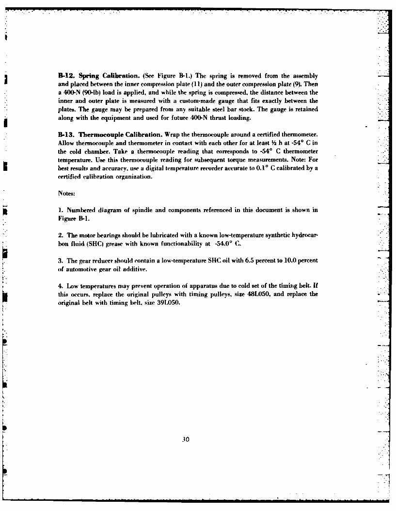
B-12. Spring Calibration. (See Figure B-I.) The spring is removed from the assemblyand placed between the inner compression plate (11) and the outer compression plate (9). Thena 400-N (90-1b) load is applied, and while the spring is compressed, the distance between theinner and outer plate is measured with a custom-made gauge that fits exactly between theplates. The gauge may be prepared from any suitable steel bar stock. The gauge is retainedalong with the equipment and used for future 400-N thrust loading.
B-13. Thermocouple Calibration. Wrap the thermocouple around a certified thermometer.Allow thermocouple and thermometer in contact with each other for at least h at -540 C inthe cold chamber. Take a thermocouple reading that corresponds to -54° C thermometertemperature. Use this thermocouple reading for subsequent torque measurements. Note: Forbest results and accuracy, use a digital temperature recorder accurate to 0.10 C calibrated by acertified calibration organization.
Notes:
1. Numbered diagram of spindle and components referenced in this document is shown inFigure B-i.
2. The motor bearings should be lubricated with a known low-temperature synthetic hydrocar-bon fluid (SHC) grease with known functionability at -54.0' C.
3. The gear reducer should contain a low-temperature SHC oil with 6.5 percent to 10.0 percentof automotive gear oil additive.
4. Low temperatures may prevent operation of apparatus due to cold set of the timing belt. Ifthis occurs, replace the original pulleys with timing pulleys, size 48L050, and replace theoriginal belt with timing belt, size 39L050.
30
APPENDIX C
LIFE PERFORMANCE OF AUTOMOTIVE WHEEL BEARING GREASES
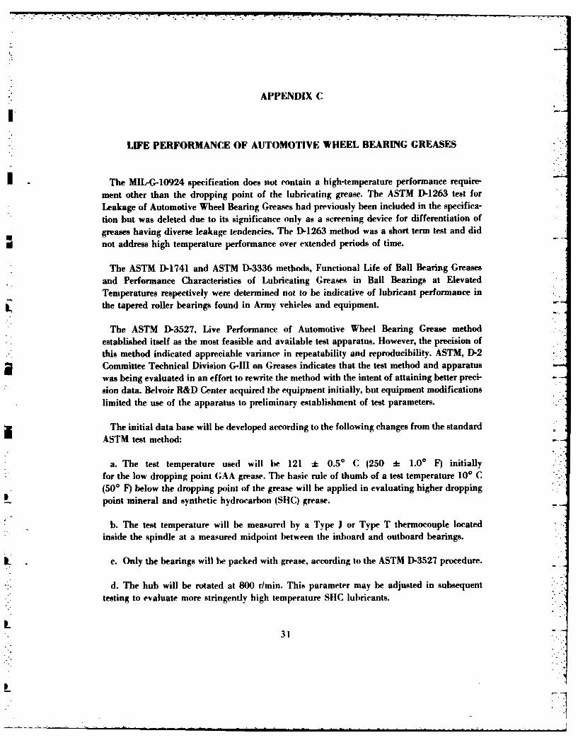
The MIL-G-10924 specification does not contain a high-temperature performance require-
ment other than the dropping point of the lubricating grease. The ASTM D-1263 test for
Leakage of Automotive Wheel Bearing Greases had previously been included in the specifica-
tion but was deleted due to its significance only as a screening device for differentiation of
greases having diverse leakage tendencies. The D-1263 method was a short term test and did
not address high temperature performance over extended periods of time.
The ASTM D-1741 and ASTM D-3336 methods, Functional Life of Ball Bearing Greasesand Performance Characteristics of Lubricating Greases in Ball Bearings at ElevatedTemperatures respectively were determined not to be indicative of lubricant performance inthe tapered roller bearings found in Army vehicles and equipment.
The ASTM D-3527, Live Performance of Automotive Wheel Bearing Grease methodestablished itself as the most feasible and available test apparatus. However, the precision ofthis method indicated appreciable variance in repeatability and reproducibility. ASTM, D-2Committee Technical Division G-I1 on Greases indicates that the test method and apparatuswas being evaluated in an effort to rewrite the method with the intent of attaining better preci-sion data. Belvoir R&D Center acquired the equipment initially, but equipment modificationslimited the use of the apparatus to preliminary establishment of test parameters.
The initial data base will be developed according to the following changes from the standardASTM test method:
a. The test temperature used will be 121 :- 0.50 C (250 - 1.0' F) initially
for the low dropping point GAA grease. The basic rule of thumb of a test temperature 100 C(50O F) below the dropping point of the grease will be applied in evaluating higher dropping
point mineral and synthetic hydrocarbon (SHC) grease.
b. The test temperature will be measured by a Type J or Type T thermocouple locatedinside the spindle at a measured midpoint between the inboard and outboard bearings.
c. Only the bearings will be packed with grease, according to the ASTM D-3527 procedure.
d. The hub will be rotated at 800 r/min. This parameter may be adjusted in subsequent
testing to evaluate more stringently high temperature SHC lubricants.
31
p .
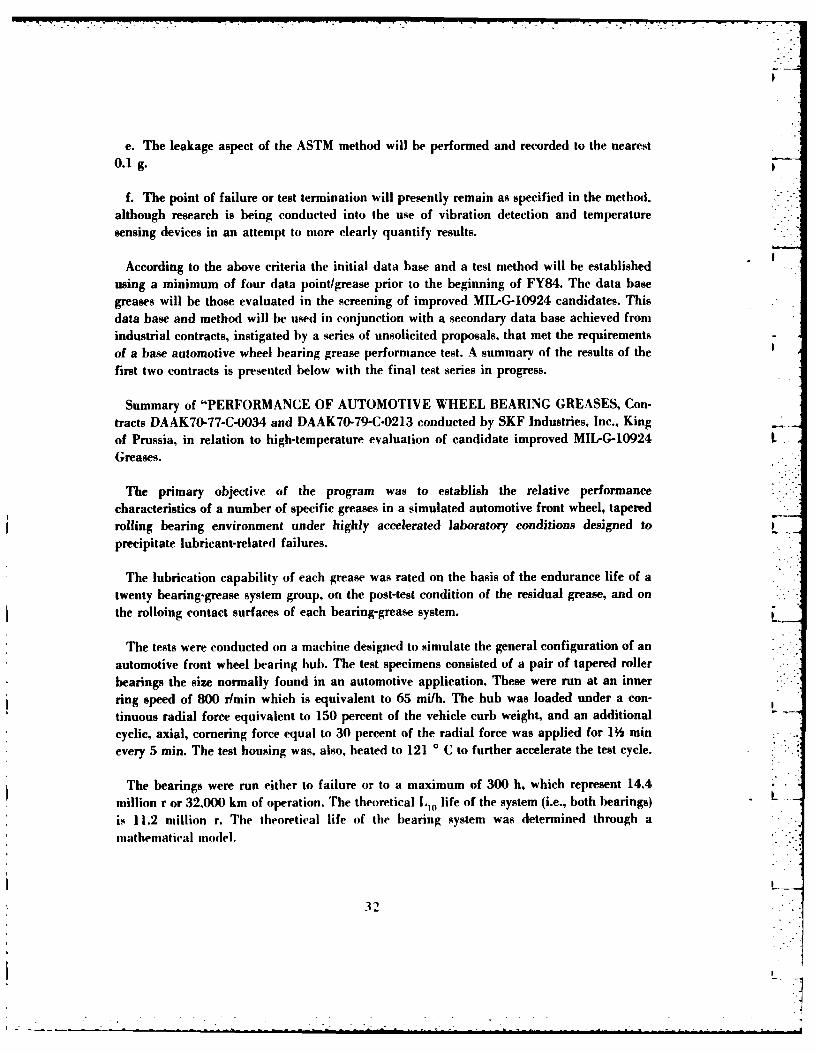
e. The leakage aspect of the ASTM method will be performed and recorded to the nearest0. 1 g.
f. The point of failure or test termination will presently remain as specified in the method.although research is being conducted into the use of vibration detection and temperaturesensing devices in an attempt to more clearly quantify results.
According to the above criteria the initial data base and a test method will be establishedusing a minimum of four data point/grease prior to the beginning of FY84. The data basegreases will be those evaluated in the screening of improved MIL-G-10924 candidates. Thisdata base and method will be used in conjunction with a secondary data base achieved fromindustrial contracts, instigated by a series of unsolicited proposals, that met the requirementsof a base automotive wheel bearing grease performance test. A summary of the results of thefirst two contracts is presented below with the final test series in progress.
Summary of "PERFORMANCE OF AUTOMOTIVE WHEEL BEARING GREASES, Con-tracts DAAK70-77-C-0034 and DAAK70-79-C-0213 conducted by SKF Industries, Inc., Kingof Prussia, in relation to high-temperature evaluation of candidate improved MIL-G-10924 LGreases.
The primary objective of the program was to establish the relative performancecharacteristics of a number of specific greases in a simulated automotive front wheel, taperedrolling bearing environment under highly accelerated laboratory conditions designed toprecipitate lubricant-related failures.
The lubrication capability of each grease was rated on the basis of the endurance life of atwenty bearing-grease system group, on the post-test condition of the residual grease, and on
the rolloing contact surfaces of each bearing-grease system.
The tests were conducted on a machine designed to simulate the general configuration of an
automotive front wheel bearing hub. The test specimens consisted of a pair of tapered rollerbearings the size normally found in an automotive application. These were run at an inner
ring speed of 800 rlmin which is equivalent to 65 mi/h. The hub was loaded under a con-tinuous radial force equivalent to 150 percent of the vehicle curb weight, and an additionalcyclic, axial, cornering force equal to 30 percent of the radial force was applied for 1 minevery 5 min. The test housing was, also, heated to 121 0 C to further accelerate the test cycle.
The bearings were run either to failure or to a maximum of 300 h, which represent 14.4million r or 32,000 km of operation. The theoretical L,0 life of the system (i.e., both bearings) Lis 11.2 million r. The theoretical life of the bearing system was determined through amathematical model.
32
2.
-: -. - - - = ., :. - . , :/ . .- - .. , .. . . .T ._ . _ .. _ . ... : . -. -.-I -*-I- - - . . . - . .I . . . -
i
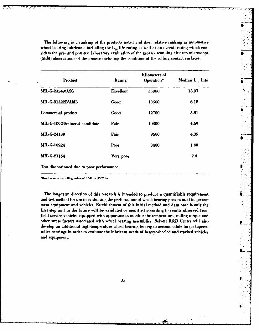
The following is a ranking of the products tested and their relative ranking as automotivewheel bearing lubricants including the LH, life rating as well as an overall rating which con-siders the pre- and post-test laboratory evaluation of the greases scanning electron microscope p(SEM) observations of the greases including the condition of the rolling contact surfaces.
Kilometers ofProduct Rating Operation* Median 110 Life
MIL-G-23549/ASG Excellent 35000 15.97
MIL-G-81322B/AM3 Good 13500 6.18
Commercial product Good 12700 5.81
MIL-G-10924/mineral candidate Fair 10300 4.69
MIL-G-24139 Fair 9600 4.39 p
MIL-G-10924 Poor 3400 1.68
MIL-G-21164 Very poor 2.4
Test discontinued due to poor performance. p
*Based upon a tire rolling radius of 0.341 m (13.75 in.).
The long-term direction of this research is intended to produce a quantifiable requirementand test method for use in evaluating the performance of wheel bearing greases used in govern-ment equipment and vehicles. Establishment of this initial method and data base is only thefirst step and in the future will be validated or modified according to results observed fromfield service vehicles equipped with apparatus to monitor the temperature, rolling torque andother stress factors associated with wheel bearing assemblies. Belvoir R&D Center will alsodevelop an additional high-temperature wheel bearing test rig to accommodate larger taperedroller bearings in order to evaluate the lubricant needs of heavy-wheeled and tracked vehiclesand equipment.
33
33 [
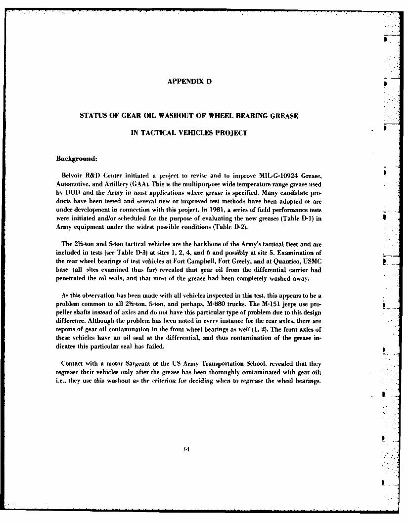
APPENDIX D
STATUS OF GEAR OIL WASHOUT OF WHEEL BEARING GREASE
IN TACTICAL VEHICLES PROJECT
Background:
Belvoir R&D Center initiated a project to revise and to improve MIL-G-10924 Grease,Automotive, and Artillery (GAA). This is the multipurpose wide temperature range grease usedby DOD and the Army in most applications where grease is specified. Many candidate pro-ducts have been tested and several new or improved test methods have been adopted or areunder development in connection with this project. In 1981, a series of field performance testswere initiated and/or scheduled for the purpose of evaluating the new greases (Table D-1) inArmy equipment under the widest possible conditions (Table D-2).
The 2 -ton and 5-ton tactical vehicles are the backbone of the Army's tactical fleet and areincluded in tests (see Table D-3) at sites 1, 2, 4, and 6 and possibly at site 5. Examination ofthe rear wheel bearings of test vehicles at Fort Campbell, Fort Greely, and at Quantico, USMCbase (all sites examined thus far) revealed that gear oil from the differential carrier hadpenetrated the oil seals, and that most of the grease had been completely washed away.
As this observation has been made with all vehicles inspected in this test, this appears to be aproblem common to all 2 -ton, 5-ton, and perhaps, M-880 trucks. The M-151 jeeps use pro-peller shafts instead of axles and do not have this particular type of problem due to this designdifference. Although the problem has been noted in every instance for the rear axles, there arereports of gear oil contamination in the front wheel bearings as well (1, 2). The front axles ofthese vehicles have an oil seal at the differential, and thus contamination of the grease in-dicates this particular seal has failed.
Contact with a motor Sargeant at the US Army Transportation School, revealed that theyregrease their vehicles only after the grease has been thoroughly contaminated with gear oil;i.e., they use this washout as the criterion for deciding when to regrease the wheel bearings.
34I
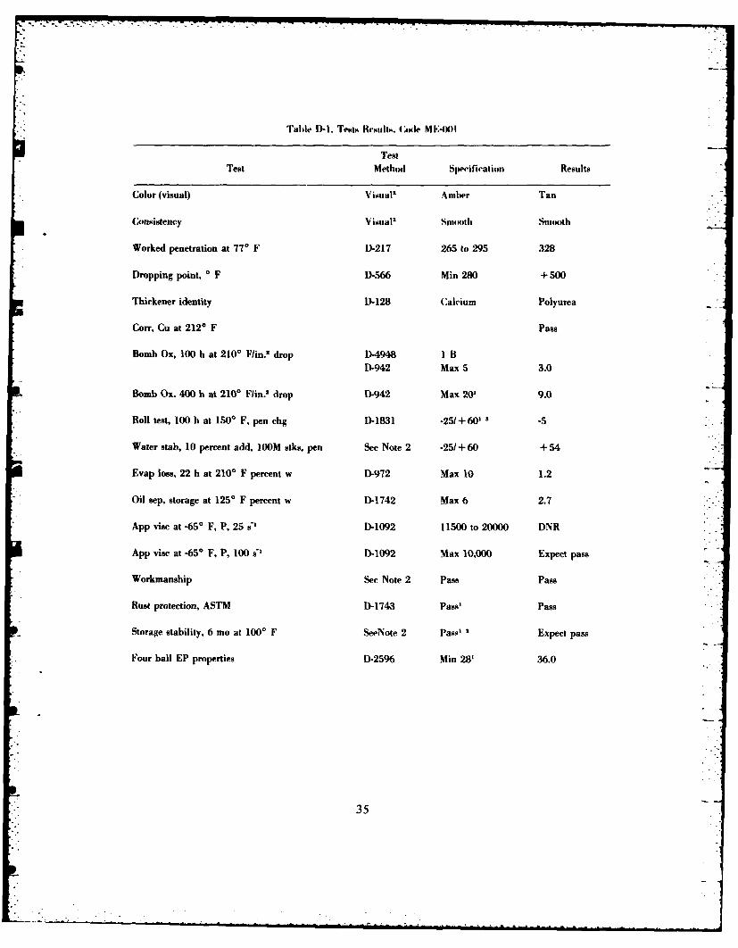
Table D-1. Tests Resualts. Code ME'49H1
TestTest Method Specification Results
Color (visual) Visual' Amber Tan
Consistency Visual, SIUItl Smoooth
Worked penetration at 770 F D-217 265 to 295 328
Dropping point, *F D-566 Min 280 + 500
Thickener identity D-128 Calcium Polyurea
Corr, Cu at 2120 F Pass
Bomb Ox, 100 h at 2100 F/in.' drop D-4948 1 BD-942 Max 5 3.0
Bomb Ox, 4010 h at 2100 Flun.2 drop D-942 Max 20' 9.0
Roll test, 100 h at 1500 F, pen chg D-1831 -25/+60'' -5
Water stab, 10 percent add, 100M stks, pen See Note 2 -25/1+60 + 54
Evap loss, 22 h at 2100 F percent w D-972 Max 10 1.2
Oil sep. storage at 1250 F percent w D-1742 Max 6 2.7
App vise at -65' F, P, 25 s'l D-1092 11500 to 20000 DNR
App vise at -6(5* F, P, 100 s' D-1092 Max 10,000 Expect pass
Workmanship See Note 2 Pass Pass
Rust protection, ASTM D-1743 Pass' Pass
Storage stability, 6 mo at 100' F SeeNote 2 Pass' Expect pass
Four ball EP properties D-2596 Min 28' 36.0
35
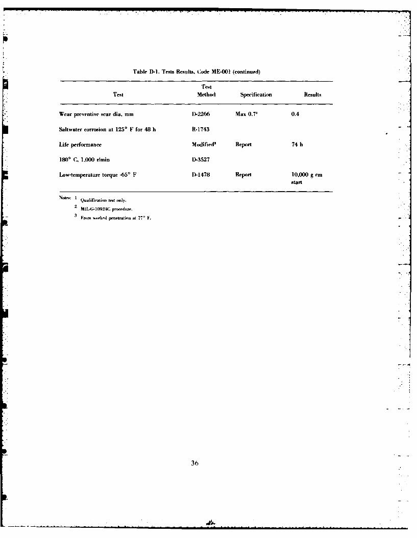
Table D-1. Tests Results, Code ME-001 (continued)
TestTest Method Specification Results
Wear preventive %car dia. mm D)-2266 Max 0.7' 0.4
Saltwater corrosion at 125' F for 48 ht R- 1743
Life performance Modified" Report 74 h
*1800 C, 1,000 rlmin D-3527
Low-temperature torque -65' F D-1478 Report 10,000 g cmstart
Not": I Qualiition legt only.
2 MIL-G-10924C proceduire.
3Fromt wotrkedI penetrationi at 77' .
36
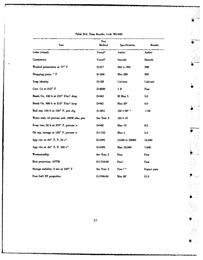
Table D-2. Tests Results, Code MIE-020
TestTest Method Specification Results
Color (visual) Visual" Amber Amber
Consistency Visual' Smooth Smooth
Worked penetration at 770 F D)-217 265 to 295 288
Dropping point, 0 F D-566 Min 280 302
Soap identity D-128 Calcium Calcium
Coff, Cu at 212*F D-4849 IlB Pass
Bomb Ox, 100 h at 2100 F/in.t drop D-942 M Max 5 3.0
Bomb Ox, 400 h at 2100 F/in.2 drop D-942 Max 20' 4.0
Roll test, 100 h at 1500 F. pen dig D-1831 -25+60 3 +50
Water stab, 10 percent add, loom stke, pen See Note 2 -25/+10
Evap loss, 22 h at 2100 F, percent w D-942 Max 10 8.3
Oil sep. storage at 125' F, percent w D-1742 Max 6 2.3
App vise at -65' F, P, 25 s0 D-1092 11500 to 20000 12,500
App visc at -65" F, P, 100 s" D-1092 Max 10,000 7,600
Workmanship See Note 2 Pass Pass
Rust protection. ASTM D-1743-00 Pams' Pass
Storage stability, 6 mo at 1000 F See Note 2 pass 2 2 Expect pass
Four ball EP properties D-2596-00 Min 28' 31.9
37

Table D1-2. Tests Results, Code ME-020 (continued)
Test
Test Method Specification Results
Wear preventive sear dia. mm
Saltwater corrosion at 1250 F for 48 It D- 1743
Life Performance Modified" Report 27.5 bt
1800 C 1,000 rimin D-3527
Low-temperature torque D-1478 Report 5622 g cmt 4
start
IQualification test only.
2 MIL-G-10924C procedure.
3 From worked penetration at 770 F.
38
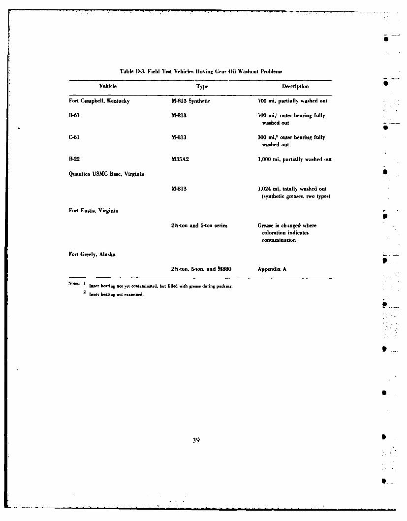
Table D-3. Fieldi Test Vehiclem s ving Gear Oil Washout Problems
Vehicle Type Description
Fort Campbell. Kentucky M-813 Synthetic 700 mi. partially washed out
B-61 M-813 100 mi, outer bearing fullywashed out
C-61 M-813 300 mi,s outer bearing fullywashed out
B-22 M35A2 1,000 mi, partially washed out
Quantico USMC Base, Virginia
M-813 1,024 uti, totally washed out(synthetic greases, two types)
Fort Eustis, Virginia
2Y%-ton and 5-ton series Grease is chainged wherecoloration indicatescontamination
Fort Greely, Alaska
2%~-ton, 5-ton, and M880 Appendix A
Notes: Im Inehearing not yet contaminated. but filled with grease during packing.
2 tnner bearing not examsined.
39
These tactical vehicles use commercial axles and PS Magazine ran an article on this problemin 1983. The position of the US Army on wheel bearing lubrication has been that grease is themethod of choice (as opposed to oil). However, some vehicles use oil lubrication (M1, M2, M3,and M-915s) for no apparent reason. The US Army has converted most of the tracked vehiclesto grease lubrication with M109 series being the most recent change over (2). Field perfor-mance testing of MJLPG-10924 (GAA) grease products in scheduled to include a grease test on 0the wheel bearings of the vehicles listed above as using oil since oil lubricated systems in-variably exhibit the standard problems of leakage, etc., know to occur in Army equipment.The field testing of improved Military grease has revealed, thus far, a major problem whichseverely limits, not only the effectiveness of the current grease and nearly invalidates its use,but also impacts directly on any improved grease used for these systems. This impact couldlimit the program so severely that without a solution no grease, regardless of its qualities,would improve the situation.
Objective:
The objective of this project is to define the gear oil washout problem sufficiently so thatrecommendations toward a solution can be made. Two possibilities are most likely: (1) thesystem is not sealed sufficiently, and (2) the seals observed were beyond their useful life.Regreasing the wheel bearings or failure to regrease the bearings twice yearly is not the causeof this problem, and unless the effective lifetime of the seals is less than six months, poormaintenance is not suspected to be a factor in this problem. Thus, this system problem severely 1impacts on the lubricants(s), and a change in the lubricants will not eliminate the problem.
Approach:
The approach used in this project is two-fold: (1) continuation of field testing at the siteswhere testing is already being performed (or scheduled to start) but with re-emphasis on resolv-ing this problem and, (2) in-house studies using an axle or axles from a 2 -ton truck as a teststand. This testing is scheduled to include high temperature and mileage to determine howmany miles a vehicle can be expected to remain greased in this kind of environment.
4 0
Thsetctcl eice uecomecalale ndP Mgziera a rtce nths4r0emI
Results:
A. Field Test. The field tests at Fort Campbell were monitored on two occasions, andin both instances (Table D-4), the rear axles of 2 -ton and 5-ton trucks showed washout of thegrease, even after only a few hundred miles. The new synthetic grease did last longer, but thehub was inadvertently packed full of the grease. Fort Greely has experienced this problemduring conversion to the new greases (the bearings and seals in this test were new) and after amonth or so of service (Addendums D-1 and D-2). The USMC has experienced the sameproblem in their tests. In particular, a new M-813 truck was greased and sent to Houghton,Michigan, for winter, cold terrain off-road testing and returned with no grease at all on therear wheel bearings. One of the four seals was observed to have a 1/8-in. gap between the bear-ing cup and seal. This would allow free pasage of the gear oil into the hub. The grease in thewell-sealed (at rest) wheels were washed aways as severely as the grease in this "non-sealed"hub. In addition, two rear outer wheel bearings at Fort Greely (NSN31104)0-087-9881) (freshlyopened and new) were different in their width. When placed in the cup on a flat surface withthe outer side upwards, the one bearing could be sealed (contact was made between the sealand cup), but the other left a 1/8-in, crack and, thus, could not seal under any conditions.Although the cups and seals were all identical, it was the bearing(s) which had differentwidths. These bearings were obtained from the supply system under the same NSN (above) andopened in the presence of Belvoir R&D Center personnel.
B. In-House Testing. The in-house testing began with solubility tests of various greasesand grease types in gear oil MIL-L-2105 (GO-90). These results, listed in Table D-5, show GAAto be completely soluble in gear oil and all of the other greases are nearly completely dissolved.No heat was added. However, since the differentials operate at high temperatures, the washouteffect would be even more pronounced (i.e., the grease would be more readily dissolved orwashed out).
Initial hub and bearing tests (Table D-5) were conducted using a mockup of a constantvelocity joint complete with hub and bearings (no wheel). The results of these tests indicatedthat, once in the hub, the gear oil readily washed away the greases (all types tested).
A rear axle was examined for inner seals at the differential and none are present.TM-9-2320-209-35 also shows this (Figure D-1) but they are shown to be present in the frontaxles (Figure D-2).
The absence of inner seals means that the entire axle assembly is wet, or rather accessibleto the gear .1, from the differential out to the hub. The differential should not be filled pastthe lower part of the differential bowl, but any time the truck is jacked up, is on a hill or hits abump in the road, the oil can be thrown out into the axles. The turning of the gears in the dif-ferential may throw the oil out of the bowl into the axles (particularly at higher speeds).
41
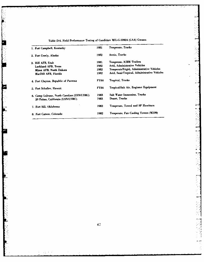
Table D-4. Field Performance Testing of Candidate MIIPG-10924 (GAA) Greases
1. Fort Campbell, Kentucky 1981 Temperate, Trucks
2. Fort Greely, Alaska 1982 Arctic, Trucks
3. Hill AFB, Utah 1981 Temperate, ICBM Trailers
Lackland AFB, Texas 1982 Arid, Administrative Vehicles
Minot AFB, North Dakota 1982 Temperate/Frigid, Administrative Vehicles
MacDill AFB, Florida 1982 Arid, Semi-Tropical, Administrative Vehicles
4. Fort Clayton, Republic of Panama FY84 Tropical, Trucks
5. Fort Shafter, Hawaii FY84 Tropical/Salt Air, Engineer Equipment
6. Camp LeJeune, North Carolina (USN/USMC) 1983 Salt Water Immersion, Trucks
29 Palms, California (USNIUSMC) 1983 Desert, Trucks
7. Fort Sill. Oklahoma 1983 Temperate, Towed and SP Howitzers
8. Fort Carson, Colorado 1982 Temperate. Fan Cooling Towers (M109)
42
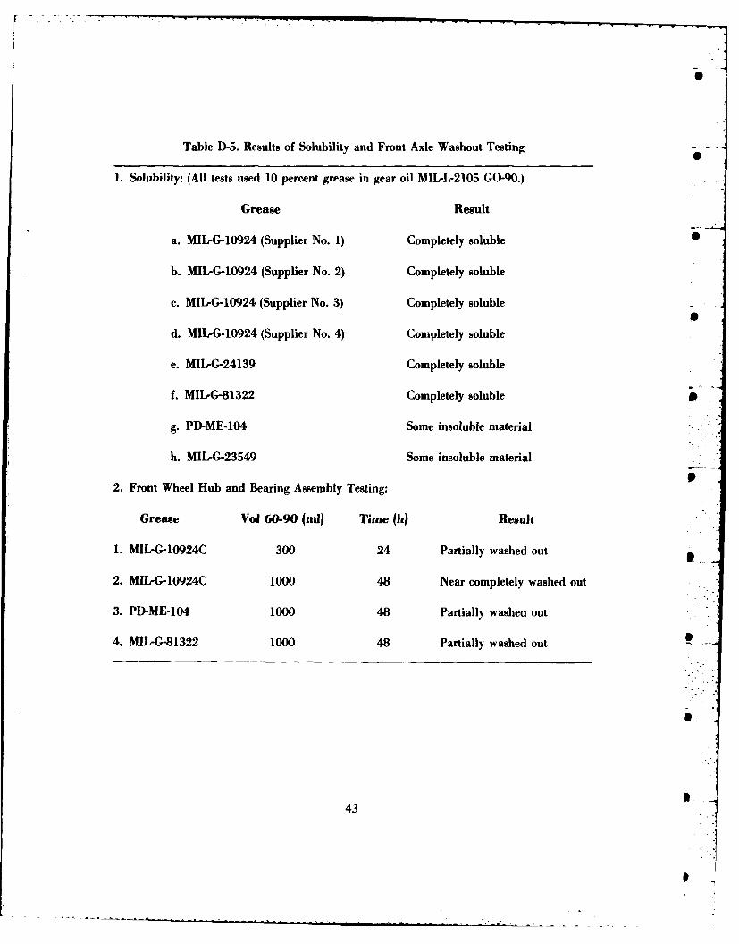
Table D-5. Results of Solubility and Front Axle Washout Testing- -
1. Solubility: (All tests used 10 percent grease in gear oil MIL-L-2105 GO-90.)
Grease Result
a. MIL-G-10924 (Supplier No. 1) Completely soluble
b. Mllr-.10924 (Supplier No. 2) Completely soluble
c. MIl-G-10924 (Supplier No. 3) Completely soluble
d. MIIPG-10924 (Supplier No. 4) Completely soluble
e. MIL-G-24139 Completely soluble
f. MIL-G-81322 Completely soluble
g. PD-ME-104 Some insoluble material
h. MIL-G-23549 Some insoluble material
2. Front Wheel Hub and Bearing Assembly Testing:
Grease Vol 60-90 (ml? Time (h) Result
1. MIL.G-10924C 300 24 Partially washed out
2. MIL-G-10924C 1000 48 Near completely washed out
3. PD-ME-104 1000 48 Partially washed out
4. MIL-G-81322 1000 48 Partially washed out -
43
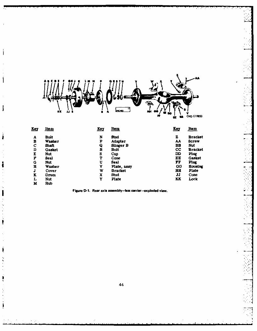
CC~ ORD EI19S
Ke Item Key Itraji Item
IA Bolt N Stud Z BracketB Washer P Adapter AA ScrewC Shaft Q Slinger B BB NutD Gasket R Bolt CC BracketE Nut S CUP DD PlugF Seal T Cone EE GasketG Nut U Seal FF PlugH Washer V Plate, assy GG HousingJ Cover W Bracket HH PlateK Drum X Stud JJ ConeL Nut Y Plate KK LockM Hub
Figure D-1. Reaw axle assembly-less carrier-exploded view. -
44
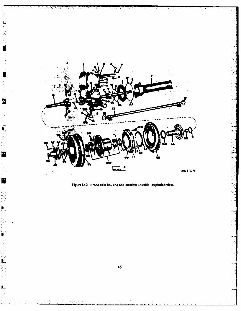
- ----- lt
I
VU T z
Figure D-2. Front axle housing and steering knuckle-exploded view.
45
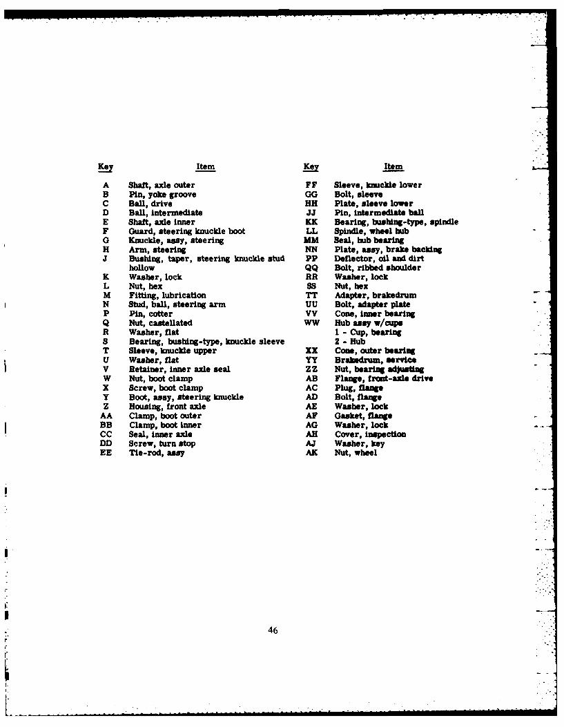
Key Item Item
A Shaft, axle outer FF Sleeve, knuckle lowerB Pin, yoke groove GG Bolt, sleeveC Ball, drive HH Plate, sleeve lowerD Ball, intermediate JJ Pin, intermediate ballE Shaft, axle inner KK Bearing, bushing-type, spindleF Guard, steering knuckle boot LL Spindle, wheel hubG Knuckle, assy, steering MM Seal, hub bearingH Arm, steering NN Plate, assy, brake backingJ Bushing, taper, steering knuckle stud PP Deflector, oil and dirt
hollow QQ Bolt, ribbed shoulderK Washer, lock RR Washer, lockL Nut, hex SS Nut, hexM Fitting, lubrication TT Adapter, brakedrumN Stud, ball, steering arm UU Bolt, adapter plateP Pin, cotter VV Cone, Inner bearingQ Nut, castellated WW Hub assy w/cupeR Washer, flat I - Cup, bearingS Bearing, bushing-type, knuckle sleeve 2 - HubT Sleeve, knuckle upper XX Con, outer bearingU Washer, flat YY Brakedrum, serviceV Retainer, inner axle seal ZZ Nut, bearing adjustingW Nut, boot clamp AB Flange, front-axle driveX Screw, boot clamp AC Plug, flangeY Boot, assy, steering knuckle AD Bolt, flangeZ Housing, front axle AE Washer, lock
AA Clamp, boot outer AF Gasket, flangeBB Clamp, boot inner AG Washer, lockCC Seal, inner axle AH Cover, InspectionDD Screw, turn stop AJ Washer, keyEE Tie-rod, assy AK Nut, wheel
46
46]
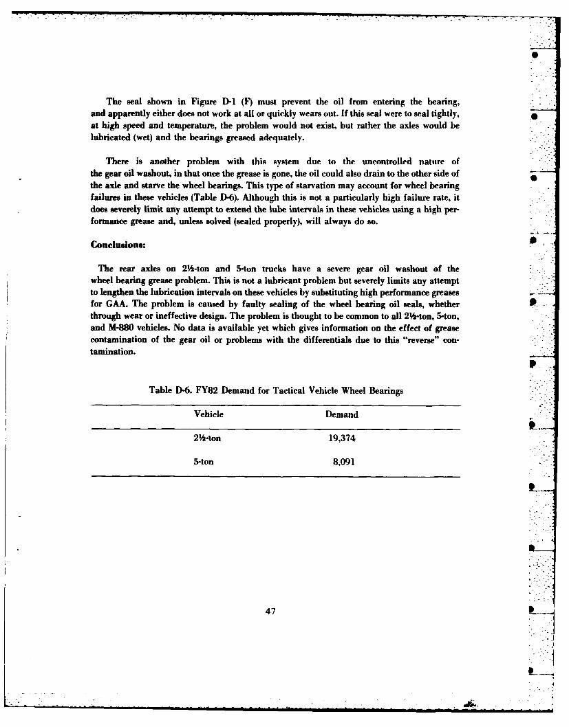
The seal shown in Figure D-1 (F) must prevent the oil from entering the bearing,and apparently either does not work at all or quickly wears out. If this seal were to seal tightly,at high speed and temperature, the problem would not exist, but rather the axles would belubricated (wet) and the bearings greased adequately.
There is another problem with this system due to the uncontrolled nature ofthe gear oil washout, in that once the grease is gone, the oil could also drain to the other side ofthe axle and starve the wheel bearings. This type of starvation may account for wheel bearingfailures in these vehicles (Table D-6). Although this is not a particularly high failure rate, itdoes severely limit any attempt to extend the lube intervals in these vehicles using a high per-formance grease and, unless solved (sealed properly), will always do so.
Conclusions:
The rear axles on 2 -ton and 5-ton trucks have a severe gear oil washout of thewheel bearing grease problem. This is not a lubricant problem but severely limits any attemptto lengthen the lubrication intervals on these vehicles by substituting high performance greasesfor GAA. The problem is caused by faulty sealing of the wheel bearing oil seals, whether P.through wear or ineffective design. The problem is thought to be common to all 2 -ton, 5-ton,and M-880 vehicles. No data is available yet which gives information on the effect of greasecontamination of the gear oil or problems with the differentials due to this "reverse" con-tamination.
p
Table D-6. FY82 Demand for Tactical Vehicle Wheel Bearings
Vehicle Demand
2 -ton 19,374
5-ton 8,091
47
. . .. 2
-79
Recommendations:
This problem should be approached by both field testing and in-house testing to determinewhat can be done to prevent this extreme oil washout from occurring. A seal sufficient for 2 yr 0of service must be developed to parallel the new grease development projects. This seal couldbe installed at the bearing, on the axle or in the differential, so long as it prevents gear oilwashout.
The effects of temperature, speed of revolution, etc., on this problem must be determined so 0that an indication of the useful life of a grease can be determined. In addition, the effect ofgrease contamination of the gear oil must be determined so that an evaluation of possiblegear/oil and/or differential damage can be performed. It is thought that the two lubricants arenot compatible and this could damage the differential and possibly lead to failure. The pro-perties of the grease are greatly modified by oil contamination, and the addition of even a Osmall amount of oil to the grease will degrade the grease structure substantially.
Reference.:
1. Twenty Truck Fuel and Lubricant Fleet Test Program, Southwest Research Institute, San PAntonio, Texas, 3 September 1968.
2. Nine Truck Fuel and Lubricant Fleet Test Program, Southwest Research Institute, San An-tonio, Texas, 20 October 1969.
(signed)DR. CHARLES E. CHAPINResearch Chemist 0Fuels & Lubricants Division
(signed)SGT JAMES L. BEESONPetroleum Lab Technician
(Signted)
Petroleum l h Tlmician
48
• . . ..
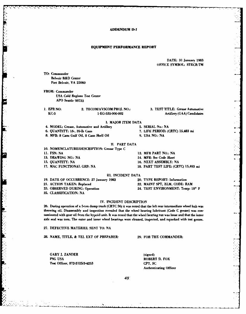
ADDENDUM D-I
EQUIPMENT PERFORMANCE REPORT
DATE: 31 January 1983OFFICE SYMBOL: STECR-TM
TO: CommanderBelvoir R&D CenterFort Belvoir, VA 22060
FROM: Commander
USA Cold Regions Test CenterAPO Seattle 98733
1. EPR NO: 2. TECOMJAVSCOM PROJ. NO.: 3. TEST TITLE: Grease AutomotiveKC-3 1-EG-535-000-002 Artillery (GAA) Candidates
1. MAJOR ITEM DATA4. MODEL: Grease, Automotive and Artillery 5. SERIAL No.: NA6. QUANTITY: 16-, 35-lb Cans 7. LIFE PERIOD: (CRTC) 15,483 mi8. MFR: 8 Cans Gulf Oil, 8 Cans Shell Oil 9. USA NO.: NA
II. PART DATA10. NOMENCLATURE/DESCRIPTION: Grease Type C11. FSN: NA 12. MFR PART NO.: NA13. DRAWING NO.: NA 14. MFR: See Code Sheet15. QUANTITY: NA 16. NEXT ASSEMBLY: NA17. MAC FUNCTIONAL GRP: NA 18. PART TEST LIFE: (CRTC) 15,493 mi
I11. INCIDENT DATA19. DATE OF OCCURRENCE: 27 January 1983 20. TYPE REPORT: Information21. ACTION TAKEN: Replaced 22. MAINT SPT, ELM, CODE: RAM23. OBSERVED DURING: Operation 24. TEST ENVIRONMENT: Temp: 180 F25. CLASSIFICATION: NA
IV. INCIDENT DESCRIPTION26. During operation of a 5-ton dump truck (CRTC 56) it was noted that the left rear intermediate wheel hub wasthrowing oil. Disassembly and inspection revealed that the wheel bearing lubricant (Code C grease) was con-taminated with gear oil from the hypoid unit. It was noted that the wheel bearing nut was loose and that the inneraxle seal was torn. The outer and inner wheel bearings were cleaned, inspected, and repacked with test grease.
27. DEFECTIVE MATERIEL SENT TO: NA
28. NAME, TITLE, & TEL EXT OF PREPARER: 29. FOR THE COMMANDER:
GARY J. ZANDER (signed)PSG USA ROBERT D. FOXTest Officer, 872-2125/3-4253 CPT, SC
Authenticating Officer
49.
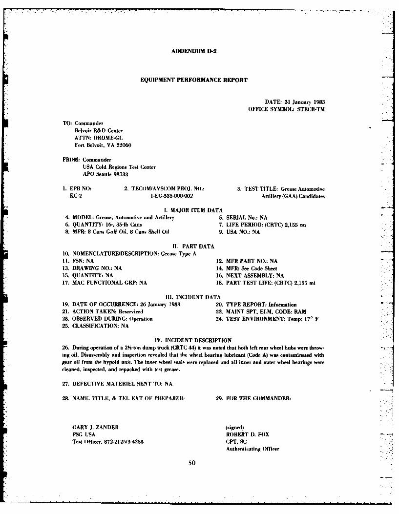
ADDENDUM D-2
EQUIPMENT PERFORMANCE REPORT
DATE: 31 January 1983OFFICE SYMBOL: STECR-TM
TO: CommanderBelvoir R&D CenterATTN: DRDME-GLFort Belvoir, VA 22060
FROM: CommanderUSA Cold Regions Test CenterAPO Seattle 98733
1. EPR NO: 2. TECOMIAVSCOM PROJ. NO.: 3. TEST TITLE: Grease AutomotiveKC-2 I-EG-535-000-002 Artillery (GAA) Candidates
I. MAJOR ITEM DATA4. MODEL: Grease, Automotive and Artillery 5. SERIAL No.: NA6. QUANTITY: 16-, 35-lb Cans 7. LIFE PERIOD: (CRTC) 2,155 mi8. MFR: 8 Cans Gulf Oil, 8 Cans Shell Oil 9. USA NO.: NA
1I. PART DATA10. NOMENCLATURE/DESCRIPTION: Grease Type A11. FSN: NA 12. MFR PART NO.: NA13. DRAWING NO.: NA 14. MFR: See Code Sheet15. QUANTITY: NA 16. NEXT ASSEMBLY: NA17. MAC FUNCTIONAL GRP: NA 18. PART TEST LIFE: (CRTC) 2,155 mi
Ill. INCIDENT DATA19. DATE OF OCCURRENCE: 26 January 1983 20. TYPE REPORT: Information21. ACTION TAKEN: Reserviced 22. MAINT SPT, ELM, CODE: RAM23. OBSERVED DURING: Operation 24. TEST ENVIRONMENT: Temp: 170 F25. CLASSIFICATION: NA
IV. INCIDENT DESCRIPTION26. During operation of a 2 -ton dump truck (CRTC 44) it was noted that both left rear wheel hubs were throw-ing oil. Disassembly and inspection revealed that the wheel bearing lubricant (Code A) was contaminated withgear oil from the hypoid unit. The inner wheel seals were replaced and all inner and outer wheel bearings werecleaned, inspected, and repacked with test grease.
27. DEFECTIVE MATERIEL SENT TO: NA
28. NAME. TITLE, & TEL EXT OF PREPARER: 29. FOR THE COMMANDER:
GARY J. ZANDER (signed)PSG USA ROBERT D. FOXTest Officer, 872-212513-4253 CPT, Sc
Authenticating Officer
50
APPENDIX E
LETTER REPORT
28 June 1983
Title: Status of Van-Axial Fan Cooling Tower Lubrication Project
Background:
The M109 Self-Propelled Howitzer was introduced in the 1950s and has seen service inseveral conflicts. This vehicle has undergone many changes and modifications over the years.For example, this gun was originally designed to have a 105-mm tube and weigh no more than30,000 lb. The M109 now carries a 155-mm tube and has a weight of 55,000 lb (1).
Several versions of this self-propelled gun are in service today; these are the M109A1,M109A2, and M109A3. These vehicles use a GMC 8V71T engine which contains a dual vane-axial fan cooling tower assembly (Figure E-1). The gearbox on the fans is grease lubricatedand when designed specified MIL-G-10924 Grease, Automotive, and Artillery (GAA). The USArmy switched over to MIL-G-23827 Grease, Aircraft and Instrument, Gear and ActivatorScrew (GIA) due to problems occurring with the fans malfunctioning and subsequently requir-ing replacement. In 1981, the US Army Armament Readiness Command (ARRCOM) publisheda Sample Data Collection report (2) describing the very high rate of failures in these fans usingMIL-G-23827. This report showed that the fans were generally incapable of meeting the ser-vice life requirements as specified in the design of the system and that each year, a fan couldbe expected to go out on half of the Ml09s in the fleet. The problem was attributed to lubrica-tion in a number of forms (e.g., failure to lubricate, lubricant breakdown, etc.).
Several contacts by users of the M109 guns were made to this office, and these contacts alsorevealed a similar problem on the MI0 (M578) series vehicles. Letterkenny Army Depotreceived numerous reports of failures in this system as well. Letterkenny Army Depot reworksthese fans, but Direct Support Shops are now reworking them locally Army-wide.
In 1982, MERADCOM (now Belvoir R&D Center) requested that the 4th Infantry Division(Mechanized) at Fort Carson, Colorado, participated in an initial limited field test of a new,high performance synthetic grease in the M109 self-propelled howitzer fan cooling tower%. -
51 __
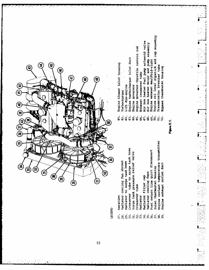
0
u 41 4) a C.)V
1. rs 4 4 4W ) 4) 044.
0 0- , s A41-0 1 i )l 4 4J 0 S
0 1 '00
.) 4440 00 k>.
I. p~( 0 U 0 S 4 U
0~. A > 41x
o ~ C4 m~ t)w 4 P4 0l -i4
C-3-
41.
00 01.4 44 0 V4
.0 i 01-4 4
4-4 01. 0d44
r.- 4) 4J :3 Jcc tyl0 4J 4 4 ) J4
004 4.) 4) (
000 A 4) 0 4) 4 JV4*40 V A = . .4 0J
0 u ~ .4 4 U-W 0 A .
0.~0 V. 0 0 0 0-01-4 1. 434 J )44- d( l4 U) CJd fd( V 9
52

Objective:
The objective of this project is to eliminate the high failure rate of fans on the M109, M 110, 5and M578 series vehicles. The initial objectives were to study the problem and to make recom-mendations to this end. Several possibilities exist as to the cause or causes of these problems:(1) incorrect or inadequate lubricant, (2) faulty design or (3) improper servicing bymaintenance personnel. Certainly, some of the problems can he attributed to lxxPrmaintenance, and the time and effort necessary just to grease the fans is an apparent design 0flaw (which may contribute to poor maintenance). Changes in procedures, the grease andpossibly even the design may be warranted in order to resolve this problem. This combinationof recommendations toward a resolution of the problem is, then, the overall objective of thisstudy. This report covers initial observations and tests as a prelude to a full-scale field test.
Approach:
The approach used in this project is two-fold; namely, an immediate, small-scale field test toestablish the potential for non-interference retrofit to a better grease, and a study of themechanical system to attempt to identify any potential areas where the observed problemsmight arise.
Procedure:
The field testing was conducted at Fort Carson, Colorado, by the units responsible for the ILguns. Table E-I gives the properties of the high performance grease used. Table E-2 gives theguns used and the type of fans they contain. No effort was made in this test to compare the testgreases with other products, except for the currently specified product (GIA). The units re-moved the old grease and used the new grease in these four guns.
Results:
A. Field Test. The testing of the new grease in the M109 self-propelled howitzer fan coolingtower gearboxes for a period of 1 yr has been successful, and no problems were encounteredeither in the field or in other use on these systems. This tends to support the possibility thatGIA is not a suitable grease for this application. However, even though there are knownproblems with GIA (oil separation, for example), this does not eliminate the possibility thatthere are additional factors involved in this problem such as the design or construction of thegearboxes. It is also possible that, within the context of this test, the maintaining units simplywere more careful of their procedures than normal and, thereby, eliminated all of the problemsassociated with poor maintenance. The one factor which is clear is that this problem can besolved with a thorough study of all the contributing factors.
53
I-.-
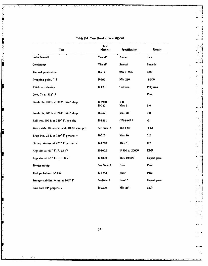
Table E-1. Tests Results. Code ME-001
TestTest Method Specification Results
Color (visual) Visual' Amber Tan
Consistency Visual' Smooth Smooth
Worked penetration D-217 265 to 295 328
Dropping point, 0 F D-566 Min 280 + 500
Thickener identity D)128 Calcium Polyurra
Co", Cui at 2120 F Pass
Bomb Ox, 100 b at 2100 Fuin.' drop D-4948 I BD-942 Max 5 3.0
Bomb Ox, 400 h at 2100 F/in.' drop D-942 Max 20' 9.0
Roll test, 100 h at 1500 F. pen chc l)-1&31 -25/ +60' .5
Water stab. 10 percent add, 1OOM stks, pen See Note 2 -25/+60 +54
Evap loss, 22 h at 2100 F percent w D-972 Max 10 1.2--
Oil sep. storage at 125' F percent w D)-1742 Max 6 2.7
App vise at -6S* F. P, 25 s' D-1092 11500 to 20000 DNR
App visec at -65' F. P, 100 D~1-1092 Max 10,000 Expect pass
Workmanship See Note 2 pass Pans
Rust Protection, ASTM D1I743 Pass' Pass
Storage stability. 6 mo at 100' F SeeNote 2 pans' 2Expect pass
Four ball EP properties D-2596 Min 28' 36.0 .*
54
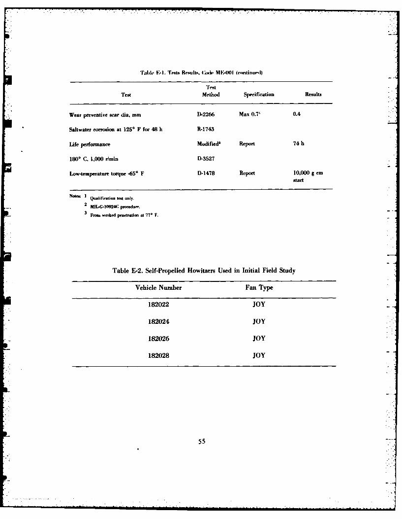
'rable' F-1. 'ITrots Restahto. (AMI* N .MA) (cintintil)
Test Method Specification Results
Wear preventive scar dia, mm D-2266 Max 0.7' 0.4
Saltwater corrosion at 1250 F for 48 It R-1743
Life performance Modified' Report 74 h
1800 C, 1,000 rltnin D-3527
Low-temperature torque -65* F D-1478 Report 10.000 g cmtstart
Noe:'Qualification test only.2 MIL-G-10924C prooedure.
3From worked penetration at 77o F.
Table E-2. Self-Propelled Howitzers Used in Initial Field Study
Vehicle Number Fan Type
182022 JOY
182024 JOY
182026 JOY
182028 JOY
55
B. System Study. There are two types of fans (technical data packages) on the M109series self-propelled howitzers (2) (Figure E-2):
1. JOY (NS 4140-00-930-4673)
2. PESCO (NSN 4140-00-756-3612)
The PESCO fans are being phased out, but are still in the system. A number of manufacturersmake the JOY fans including TASK, Sundstrand, NOA, IMC, and RONAL. Those manufac-tured by Sundstrand, NOA, and IMC were installed by BMY (Bowen-McLaughlin-York) in theM109As.
There are Depot Modification Work Orders (DMWOs) and Product Improvement Projects
(PIPs) associated with these systems. DMWO 9-2350-21711 involves rerouting the outlet valves,so that the overflow of grease does not enter the radiators and plug them.
Figure E-3 shows a schematic of the parts associated with the fan gear boxes. Figure E-4shows the parts associated with the engine cooling vane-axial fan. Figure E-4 shows a set oftwo bearings (number 15) and a single bearing (number 8) on which the drive shaft (number10.1) rides. These bearings are set inside number 9. The fan itself (number 5) is secured onto
the left end of 10.1 and turns as the shaft turns (driven by the gearbox and gear 10.1). Thisshaft rides on the three bearings (numbers 8 and 15). Bearing number 8 is an outer sealed bear-
ing and seals against lubricant loss or dirt/moisture penetration. Figure E-3 shows how thegearbox attaches to this mechanism.
In Figure E-4, number 13 is a bearing plate, which shows attachment bolt holes (the boltsare not shown). This circular plate has a hole in the center, through which the shaft (10.1)passes. This plate also acts as a seal between the gearbox and the fan carrying bearings(numbers 8, 15, and 15), and hence, little if any lubricant can pass from the gearbox (which iswhere the assembly is greased) into these three bearings. Lubricant starvation could easilyoccur under these conditions, and this could, in turn, cause failure of these bearings and the
entire assembly. The higher load which would result early in the failure process could causethe universal joints leading to the gearboxes (not shown) to wear excessively. This would leadto wear and play in the joints. Sudden engine acceleration could then cause total failure, even
through shaft breakage.
The bearing plate in question was examined at Letterkenny Army Depot during an
observation of the rework process. Four very tiny holes appear to have been drilled in the plate(these are not shown in Figure E-4) but this would by no means allow sufficient lubricant topass into the cavity. Indeed, if any benefit was derived from the use of GIA over GAA, it couldbe due to the extreme oil separation observed with GIA. The oily may be able to pass into thebeairing cavily and lubricate the hearings to a limited degree, and on a temporary basis.
56
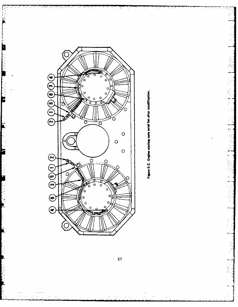
0 0..
0
LU
Srw
57
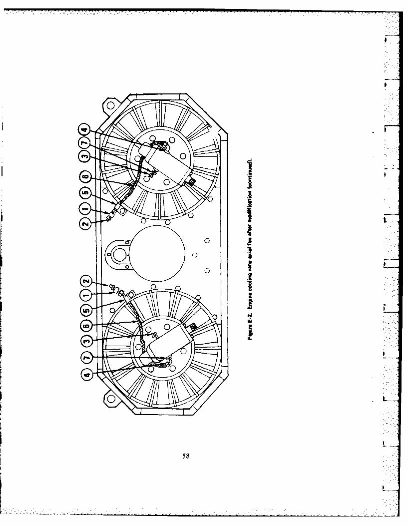
8--
81.%
no
mb
58
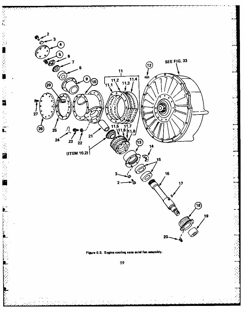
2
4
~< 71 SEE FIG. 33
9. 281i. 11.4
28 10 01. 11.
0
I.~ 027'
26, 1/. 11.725 1.6 .8
3 16
02
Fiur 26& 2nin 1.5in 11.7ail easmby
,~Eb 7'259
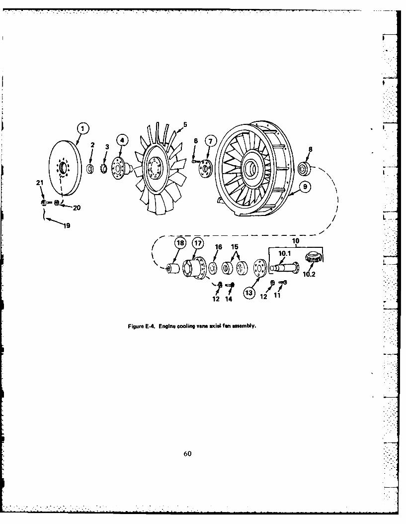
210
21 L
/~ 16 10
10.2
12 1412 1
Figure E-4. Engine cooling vane axial fan assembly.
60
* -. - - .•..]rr-r
The grease described in Table E-1 is known to be a partially thixotropic grease;i.e., it becomes liquid under sheer stress and could be expected to pass into the bearing cavitywith far greater ease than GIA and, hence, lubricate the inner fan carrying bearing set
Conclusions:
There are multiple causes for the high failure rates on M109 series self-propelledhowitzers (the fan cooling towers) which can be grouped under three categories:
1. Lubricant.
2. Design.
3. Maintenance.
These categories are interdependent; for example, if not properly maintained, --
the lubricant can fail, etc. The use of a high performance synthetic grease has been tested suc- .cesefully, even in a retrofit situation. The design of the system has been implicated in a possi-ble additional aspect of the cause of the problem.
Recommendations:
1. Expand the test to a full-scale field test (70 to 80 vehicles) and includeMl10, M578 vehicles as well.
2. Conduct in-house testing with the fan assembly to determine if lubricant starvationoccurs, and if the plate can either be removed or drilled out to a larger diameter hole (to allowlubricant passage into the fan carrying bearing cavity).
3. Develop recommendations for lubricant, Modification Work Order, or other proceduresbased on the results of the larger study.
61
References:
1. Field Artiliery journal, May-June 1983, p. 26.
2. SOC Vane Axial Fan Failure Analysis, Howitzer, Self-propelled, M109 Series-
(signed)DR. CHARLES C. CHAPINResearch ChemistFuels and Lubricants Division
(signed)SGT JAMES L. BEESONPetroleum Lab TeclinciallFuels and Lubricants Division
(signed)SP4 DAVID A. BROWNPetroleum Lab TechnicianFuels and Lubricants Division
7
62
Distribution for Beivofr R&D Center Report 2399
No. copies Addressee No. Copies Addressee
Department of Defense 7 CDRUS Army Materiel COmmand
IDirector, Technical Information ATTN: DRCLD (Dr. Gonano)Defense Advanced Research ATT'N: DRCDMR (Mr. Greiner)
Projects Agency ATTN: DRCQA-E1400 Wilson Blvd ATTN: DRCMD-ST (Dr. Haley)Arlington, VA 22209 ATTN: DRCSM-PM
ATTN: DRCDE-SSIDirector ATT~N: DRCSM-WCS (CPT Daily)
Defense Nuclear Agency 5001 Eisenhower AvenueATTN: TITL Alexandria, VA 22333Washington, DC 20305
6 CDRI12 Defense Technical Information Ctr US Army Tank-Automotive Cmd
Cameron Station ATTN: DRSTA-RAlexandria, VA 22314 ATTN: DRSTA-RG -
(Mr. W. Wheelock)ICDRI ATTN: DRSTA-RC (Mr. A. Farkus)
Defense Fuel Supply Center ATTN: DRSTA-GATTN: DFSC-T (Mr. Martin) ATTN: DRSTA-MCameron Station ATTN: DRSTA-GBPAlexandria, VA 22314 (Mr. McCartney)
Warren, MI 48091 CDRI
Defense General Supply Center 2 CDRATTN: DGSC-SSA US Army Armament, MunitionsRichmond, VA 23297 and Chemical Command
AfTN: DRSMC-LCICDR ATTN: DIISMC-SC.
US Readiness Command, Dover, NJ 07801USREDCOMIVJ4-E
MacDill AFB, FL 33608 3 DirUS Army Materiel Systems
CDRI Analysis AgencyUS Army Western Command ATTN: DRXSY-CMAMl: APLG-TR ATTN: DRXSY-SFort Schafter, HII 96858 ATTN: DRXSY-L
Aberdeen Proving Ground, MD
Department of the Army 21005
4 HQ, Dept of Army 2 CDRIATTN: DALO-TSE US Army Research OfficeATTN: DALO-AV ATTN: DRXRO-EG (Dr. Mann)ATTN: DAMA-CSS ATT'N: DRXIIO-CBATTN: DAMA-ARA (Dr. Ghirardelli)Washington, DC 20310 P. 0. Box 12211
Re~erch Triangle Park, NC
63 2~1
No. Copies Addressee No. Copies Addressee
CDR 2 CDR
US Army Depot Systems Command US Army Troop Support Command
ATTN: DRSDS ATTN: DRSTS-MEG (2)
Chambersburg, PA 17201 ATTN: DRSTS-WJ (LTC Foster)4300 Goodfellow Blvd
CDR St. Louis, MO 63120
Tobyhanna Army DepotATTN. SDSTO-TP-S 3 CDR
Tobyhanna. PA 18466 US Army General Material andPetroleum Activity
Dir ATTN: STRGPUS Army Materials & Mechanics ATTN: STRGP-F
Research Center ATTN: STRGPPE
ATTN. DRXMR-M (Mr. McKnight), Bldg 85-3
Watertown, MA 02172 New Cumberland Army DepotNew Cumberland, PA 17070
CDRUS Army Watervliet Arsenal IProject Officer, Amphibious and
ATTN: SARWY-RDD Water Craft
Watervliet, NY 12189 ATTN: DRCOP-AWC-R4300 Goodfellow Blvd
2 CDR St. Louis, MO 63120
US Army Foreign Science andTechnology Center 1CDR
ATTN: DRXST-MT 11th Transportation Battalion
ATTN: DRXST-BA (Terminal)Federal Building ATTN: AFFG-4CDB
Charlottesville, VA 22901 Fort Story, VA 23459
CDR 1CDRDARCOM Materiel Readiness US Army General Material
Support Activity (MRSA) and Petroleum Activity
ATTN: DRXMD)MD ATTN: STSGP-PW (Mr. Price)
Lexington, KY 40511 Bldg 247, Defense Depot TracyTracy. CA 95376
CDRUS Army LEA I CDR
ATTN: DALO-LEP US Army Materiel Armament
New Cumberland Army Depot Readiness Command
New Cumberland, PA 17070 ATTN: DRSAR-LEMRock Island Arsenal, IL 61299
2 HQ, US Army Test andLEvaluation Command I CDR
ATTN: DRSTE-TOM) US Army Cold Region Test Center
ATTN: DRSTE-CT ATTN: STECR-TA
Aberdeen proving (;rEotIIl, MI) APO Seattle 98733
210X05
64
No. Copies Addressee No. Copies Addressee
2 CDR 2 Pr4.g Mgr. Aloranis 'atik Syslem.US Army Research and l)AR()M
Standardization Group (Europe) ATTN: D)R(PM-4(CM-S
ATTN: l)RXSN-UK-RA AIT:DCN-CIATTN: DRXSN-IJK-SE Wilh i ~M
Box 65FPO New York 09510 1Prog Mgr, Bradely Fighting
Vehicle System
CDR ATTN: DRCPM-FVS-SE
US Army Yuma Proving Ground Warrn, MI 4809
ATTN: STEYP-MLS-M(Mr. Doebbler) 1Proj Mgr, M60 Tank Development
Yuma, AZ 85364 ATTN: DRCPM-M60EWarren, All 4809
CDRTheater Army Materiel Mgmt IProd Mgr, M113 Family of
Center (200th)-DPGM Vehicles
Directorate for Petrol Mgmt ATTN: DRCPM-M113
ATTN: AEAGD-MMC-P T-Q Warren, MI 4809
APO NY 09052 1 Proj Mgr, Mobile Electric Power
2 CDR ATTN: DRCPM-MEP-TM
US Army Europe & Seventh Army 7500 Backlick Road
ATTN: AEAGC-FMD Springfield, VA 22150
ATT1N: AEAGD-TEAPO NY 0940)3 1 Proj Mgr, Light Armored Vehicles
ATTN: DRCPM-LA
3 Department of the Army WreM 89Construction Engineering Research
Laboratoyr 1 CDRATTN: ERLEMUS Army Forces Command
ATTN: CER6ZT ATTN: AFLG-REG
ATTN: CERL-rEH Fort McPherson, GA 30330
P.O0. Box 4005Champaign, IL 61820 1 HQ
US Army Training & Doctrine
HQ, Dept of Army Command
ATTN: DAEN-DRM ATTN: ATCD-SL (MMJ Jones)
Washington, DC 20310 Fort Monroe, VA 23651
2 HQ, 172d Infantry Brigade 1HU ryAmrCne(Alaska)ATTN: ATZK-CD-SB
ATTN: AFZT-DI-L Fort Knox, KY 40121
ATTN: AFZT-DI-MDirectorate of Industrial Operations
% Fort Richardson, AK 99505
65

No. Copies Addressee No. Copies Addressee
2 CDR I CDR101st Airborne Division (AASLT) US Army Engineer SchoolATTN: AFZB..KE-J ATTN: ATZA-CDMATTN: AFZB-KE-DMMC Fort Belvoir, VA 22060
(CPT Morris)Fort Campbell, KY 42223 1 Chief, US Army Logistics
Assistance Office, FORSCOMProd Mgr, Armored Gi~mbal ATTN: DRXLA-FO (Mr. Pittman)
Vehicle Technology Fort McPherson, GA 30330ATTlN: DRCPM-CVTWarren, MI 48090 1 CDR
105th S&T Battalion -
3 CDR ATTN: LTC McLemoreUS Army Quarternaster School 5th Infantry Div (Mchl)ATTN: ATSM-CD Fort Polk, LA 71459ATTN: ATSM-TL)ATTN: ATSM-DTP 1 Southwest Research InstituteFort Lee, VA 23801 Fuels & Lubricants Division
6220 Culebra Road
2 CDR San Antonio, TX 78284US Army Arnor & Engineer BoardATTN: ATZK-AE-PD Belvofr Research andATTN: ATZK-AE-CV Development CenterFort Knox, KT 40121
I Commander, SThBE-Z2 CDR Tech Dir, STRBE-ZT
US Army Logistics Center Assoc Tech Dir, STRBE-HATTN: ATCL-C Chief Engineer, STRBE-HEATTN: ATCL-MS (Mr. Marshall) Chief Scientist, STRBE-HSFort Lee, VA 23801 Program Planning, STRBk-HP
Program Support, STRBE-HR __
CDR Systems Analysis, STRBE-HAUS Army Field Artillery School CIRCULATEATTN: ATSF-CDFort Sill. OK 73503 1 C, Combined Arms Support Lab,
STRBE-XCDR C, Engineer Support Lab, STRBE-NUS Army Transportation School C, Engineer Service Support Lab, r-
ATTN: ATSP-CD-MS STRBE..EFort Eustis, VA 23604 C, Logistics Support Lab, STRBE-G
C, Matd, Fuels & Lubricants Lab,
CDR STRBE-VUS Army Infantry School Dir, Product A&T Directorate.ATTN: ATSII-('I)-MS-M STRIIE-TFot Iliuting. G;A 31905 CIRCULATE
66
No. Copies Addres.ee No. CGopirs Addressee
3 Materials, Fuels and Lubricants I Chief of Naval Research
Lab, STRBE-V ATTN: Code 473
10 Fuels and Lubricants Div. Arlington. VA 2217STRBE-VF
3 Tech Rpts Ofe, STRBE-WPG DIR
3 Security Ofc (for liaison officers) Naval Air Engr Center
STRBE-S ATTN: C ide 92727
2 Tech Library, STRBE-WC Lakehunt, NJ 08733
1 Program Support, STRBE-IIR1 Public Affairs Ofc, STRBE-1 CDR
1 Ofc of Chief Counsel, STRBE-L Naval Sea Systems CommandAfN: Code 05M4 (Mr. Layne)
Deportment of the Air Force Washington, DC 20362
1 HQ, Air Force Systems Command 2 CDR
ATTN: AFSC/DLF (MAJ Larson) David Taylor Naval Ship Research
Andrews AFB, MD 20334 and Development CenterCode- 2830 (Mr. Bosmajian)
1 HQ, US Air Force Code: 2705.1 (Mr. Strucko)
ATTN: LEYSF (COL Custer) Annapolis, MD 21402Washington, DC 20330
1 CDR
2 CDR Naval Facilities Engr Center
US Air Force Wright Aeronautical A'TN: Code 120 (Mr. Burris)Laboratory 200 Stovall Street
ATTN: AFWAL/POSL (Mr. Jones) Alexandria, VA 22322ATTN: AFWALIMLSE (Mr. Morris)Wright-Patterson AFB, OH 45433 1 CDR
Marine Corps Logistics Support
2 CDR Base Atlantic
San Antonio Air Logistics Center ATTN: Code P841
ATN: SAALCJSFT (Mr. Makris) Albany, GA 31704 -.
ATN: SAALCJMMPRRKelly AFB, TX 78241 1 Department of the Navy
HQ, US Marine Corps
CDR ATTN: LPP (MAJ Wallace)
Warner Robins Air Logistic Center Washington, X 20380
AlN: WR-ALCIMMIRAH! -(Mr. Graham) Commanding General
Robins AFB, GA 31098 US Marine Corps Development andEducation Command
Department of the Navy AT'TN: 11074 (LTC Woodhead)Quantico, VA 22134
I CDR
Naval Air Propulsion Center
AMiN: PE-7 (Mr. D'razio)P. 0. Box 7176Trenton, NJ 06828
67
-:.. ./- --:- - : - .. . . . . . .
No. Copies Addressee
joint Oil Analysis Program-Technical Support Center
Bldg 780Naval Air StationPensacola, FL 32508
2 CDR C
Naval Materiel CommandATTN: MAT-08E (Dr. Roberts)
ATTN: MAT-08E (Mr. Ziem)
CP6. Room 606Washington, DC 20360
2 CDRNaval Research LaboratoryATTN: Code 6180ATTN: Code 6110 (Dr. Harvey)
Washington, DC 20375
CDRNaval Air Systems Command
ATTN: Code 5304CI(Mr. Weinberg)
Washington, DC 20361
CDRNaval Air Development CenterATTN: Code 60612Warminster. PA 18974
Proj Mgr, M60 Tank DevelopmentUSMC-LNO
US Army Tank-AutomotiveCommand (TACOM)
Warren, MI 4809
Naval Ship Engineering Center
ATTN: Code 6764 (Mr. Boyle)
Philadelphia, PA 19112
68
10-84
DTI0