Embed Size (px)
Citation preview
I
In Reply] Refer To: RP-2-1* A U G * 7 1 9 6 4
w !
Corpus Christi 011 ami Cas Company Attention: Joe E. tskew, J r . Post Office ~ox 2928 Corpus Chr ist i , Texas 76403
Gentlemen:
Reference 1s made to your Supplemental Plan of Exploration received August 13, 1984, for Lease OCS-G 6147, Block 36, Hioh Island Area. This plan Includes the activit ies proposed for Uells G, H, and I.
In accordance with 30 CFR 250.34, revls December 13, 1979, and our letter dated January 29, 1979, this plan has Oeen determined to be complete as of August 27, 1984, and Is now being considered for approval.
Your plan control number 1s S-l433 and should bc referenced 1n your communication and correspondence concerning this plan.
Sincerely yours.
(Orig. Sgd.) O.W. Solanas 0. W. Solanas Realonai Supervisor h Rules and Production ^
bcc: Lease OCS-G 6147 (OPS-2-3) (FILE ROOM) cflP5u?-fi y/p»hHf Jnfo. Copy of the plan (PUBLIC RECORDS ROOM) DO-3
MJTol bt i t:vjcw:8/13/84 Disk 3a
_ CfficaU rrogram Sarvicas
AUG 2 8 1984
Records Management .Section
Area Code 512 688-9301
. i CORP' S CHRISTI OIL AND GAS COMPANY IHI 600 BU11DING
P O «OX 2926
CORPUS CHRtSIl TEXAS 78403
August 10, 1984 . . ****** mmc,
' * / M i r U. S. Department o f the r n t e r i o r ^ J 0
Minerals Management Servioe O f f i c e Rules and Production Wius «.-•.... .IION P. O. Box 7944 Metair ie , louisiana 70010
Re: Supplemental Exploration Plan Block 86 High Island Area Gulf Of Mexico
Corpus Chr is t i O i l and Gas i s the designated operator of OCS-G-6147 Block 86, High Is land Area, Gulf o f Mexico and i s requesting approval o f t h i s supplemental exploratory program so that operations can be i n i t i a t e d to d r i l l on Block 8(',. This plan i s being supplemented to add three wells i n the SE/4 of the t r a c t .
Enclor i i s the - lDportive dat<»:
1. Copy of Designation o i Operator, Form 9-1123.
* 2. His tor ic Shipwreck/Prehistoric Site Survey and Shallow Geologic Hazard Survey.
3. Approval o f emergency pjan to control and remove o i l and waste s p i l l s . Updated December, 1983 and approved December 14, 1983.
4. Basic development plan and exploratory map.
5. Plat showing locations of- proposed wel ls , v e r t i c a l depths, measured depths, and water depths.
6. ALr q u a l i t y emission calculat ions.
7. Generalized mud program tc; be followed.
8. I n t o n a t i o n showing the type of d r i l l i n g r i g t o be used during the explorat ion phase.
I would appreciate your early oonsiceration o f t h i s request.
Yo.irs very t r u l y ,
/ / Jc*; E. Eskew, Jr . Vice President, Operations
* Previously Fi led JHE/"ba
r » r » f -1 l l l • ( B u l a m i t i n t r i p l i c a t e to a p ; . . j r H n U
' , , J ? « v » o n e d O U a n d G o * ca M i n i n g E u p t r r u c * )
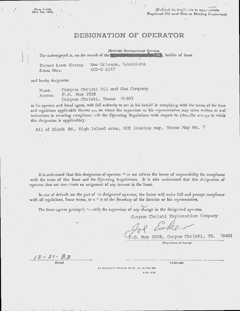
DESIGNATION OF O P E R A T O R
Minerals Management Service Thr undersigned is, oo the records of U i c • J B J H B B 9 B 9 B B B Q B 3 3 I > holder of lease
DisnucT LAND OFFICE: New Orleans, Louisiana SFJUAI Nox. OCS-G 6247
aod hereby designates
NAVE: Corpus C h r i s t i O i l and Gas Ccmpany ADDRESS: P.O. Box 2928
Corpus C h r i s t i , Texas 7£403 ai his operator aod local agent, with full authority to act io his behalf i r complying with the terms of the leasc aod regulations applicable thereto a* in oo whom the supervisor or bis representative may serve written or oral instructions io securing compliance with the Operating Regulations with respect to (doLTibe acreage to which this designation is applicable):
A l l of Block 86, High Island area, OCS leasing map, Texas Map No. 7
It is understood1 that this designation of operator J ~rs not relieve the lessee of responsibility for compliance with the terms of the lease aod the Operatiog Regulation*. I t is also understood that this designation of operator does no» constitute an assignment of any interest in tbe lease.
In case of default on the part of "ie designated operator, the lessee w i l l make f u l l and prompt compUancr wi th all regulations, lease terms, or o 3 rs of the Secretary of the Interior or his representative.
The lessee agrees promptly to notify the supervisor of any change in the designated operator.
Corpus Christi Exploration Company
-y .O. Box 2928, Corpus Ch r i s t i , TX. 78403 (Kg-oatnr* ef l r u r « ) (P-'»T..tur» ef I H . « )
(D»U) ( A c H r - . )
ua .-.««- miNiiNc c m a i w -0-72* »S4
• 10- s s i
Aroo Cod* 512 8/8-9301
CORPUS CHRISTI OIL AND GAS COMPANY THE t-00 BUILDING
PO BOX 2928
CORPUS CHRISTI. TEXAS 78403
- I
Re: OCS-G-6147 Block 86, High Island Area Gulf of rfexic©
I have reviewed the dat obtained frcm the original surveys and frcm reshcoting the magne torn or surveys in Block 86 and f ind no evidence of shallow, archaeologic, geologic or gas hazards at the additional proposed surface location. Tne additional surface location f a l l i n an area of near surface channeling but is over 1500' from the edge of the channel. The d r i l l i n g r i g w i l l be set up in an area of harder, sandy bottom and no problems are anticipated at this location. The location is over 250' fron a shallow faul t and over 1000' from the nearest magnetic anomaly.
i s V be E. Eskew, Jr.
Vice President, Operations
JCH/ba
UNITED STATES I APARTMENT OFTHEHNTER(OR * MINER - L S M A N A G E M E N T S E R V I C E
G U L F O F M E X I C O R E G I O N
I M P E R I A L O F F I C E B L D G . . 3 3 0 1 N . C A U S E W A Y B L V D .
• I " P. O . B O X 7 9 4 4
M E T A I R I E . L O U I S I A N A 7 0 0 1 0
5 0 4 - 8 3 7 - 4 7 2 0
i
In RepljJ Prefer To: .fcP-2-1 QC/Q y ± ^ 3
' f ' '
Corpus Christi Oil and^Gas Company A t t e n t i o n : Mr. Joe E. Eskew Post Off ice Box 2928 Corpus Chr i s t i , Texas 78403
Gentlemen:
With your le t te r o f December 1 , 1983, s i x copies of rev is ions to your " O i l Sp i l l Contingency Plan" were f i l e d w i t h t h i s o f f i c e .
Please amend your p l a n f o r report ing t o the Minerals Management Service as f o l l o w s :
1 . Delete Mr. Robert Goodman.
2 . Change the telephone numbers f o r Mr. Jack Sandridge to (409) 297-8401 and Mr. Clarence Kershaw to (409) 297-2703.
The revisions are hereby approved and w i l l be incorporated in to our copies o f you r plan. Please fu rn ish t h i s o f f i c e w i t h s ix copies of fu r ther rev is ions or modif icat ions o f your contingency p l a n .
S incere ly yours ,
D. W. Solanas
* U Regional Supervisor Rules and Production
! * OIL SPILL CONTROL
BLOCK 86
OorjDus Christ! ~Oi| and Gas is a member of Clean Gulf "Associates and therefore has access to their o i l s p i l l and containment equipnent. Corpus Christi Oil and Gas also has an agreement with Peterson Maritime Services Inc. to furnish nx n and materials as needed to hahdleany mir.or or major o i l s p i l l . A response to any need for the type equipment w i l l come from Galveston, Texas and response time to Block 86, High Island Area is estimated to be within 6 to 8 hours.
a^SIC EXPLORATION PIAN
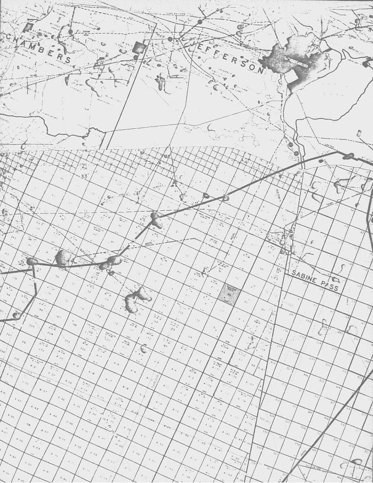
Corpus C h r i s t i O i l and Gas Ccmpany plans t o d r i l l nine wel ls t o properly explore and develope Block 86. Well A w i l l be d r i l l e d as a straight hole w i th Wells B, C, and D being d i r e c t i o n a l l y d r i l l e d from the surface locat ion f o r Well A. Wells E, F, and G w i l l be straight holes. Wells H and I w i l l be d i r ec t iona l we l l s d r i l l e d from the surface l o c a t i o n f o r we l l G. As can be seen from the attached structure map, there are f i v e separate f a u l t blocks t o be explored a t 6500', 6800', 7100', 7200', and 7500'. Other sands down to 14,000 fee t w i l l be penetrated and evaluated.
Corpus Chr i s t i O i l and Gas w i l l set s u f f i c i e n t s t r ings of casing to comply with a l l U.S.G.S. rules and containment of a l l f l u i d s i n the strata penetrated. A mud logging u n i t w i l l be on loca t ion to help evaluate a l l zones o f interest and t o monitor any gas i n the mud system. More d e t a i l e d d r i l l i n g information w i l l be given when the specif ic wel l d r i l l i n g permit i s requested.
The wells w i l l be d r i l l e d wi th a Le Tourneau jack-up r i g wi th onshore support f a c i l i t i e s i n the Sabine Pass Area. Rig a v a i l a b i l t y i s anticipated to be c " or early win te r , 1984. D r i l l i n g time i s estimated t o be 45 to 60 da;, or each w e l l w i t h a l l 9 wells t o be completed w i t h i n 15 months
Geological evaluc. .ns of each w e l l d r i l l e d may point out addit ionaj w e l l locations needed fo r optimum explorat ion development of the block.
• J
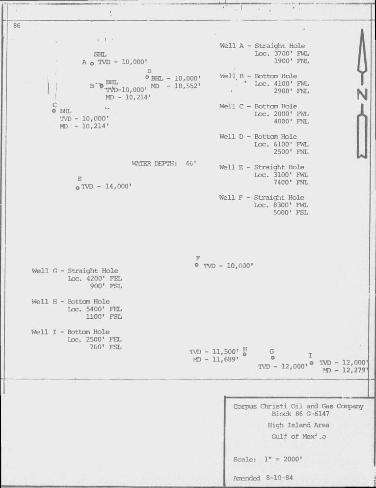
86
SHL A o IVD - 10,000'
BHL
D
° BHL - 10,000' B'^£-10,000« m - 10.552'
MD - 10,214' C Q BHL TVD - 10,000' MD - 10,214'
WATER DEPTH: 46'
E O TVD - 14,000'
Well A - Straight Hole Loc. 3700' FWL
1900' FNL i
Well B - Bottcm Hole " Loc. 4100' FWL
• 2900' FNL
Well C - Bottom Hole Loc. 2000' FWL
4000' FNL
Well D - Bottcm Hole Loc. 6100' FWL
2500' FNL
Well E - Straight Hole Loc. 3100' FWL
7400' FNL
Well F - Straight Hole Loc. 8300' FWL
5000' FSL
Well G - Straight Hole Loc. 4200' FEL
900' FSL
° TVD - 10,000'
We l l H -
Wel l I -
Bottom Hole Loc. 5400' FEL
1100' FSL
Bottom Hole Loc. 2500' FEL
7001 FSL TVD - 11,500' g
MD - 11,689' G o
N JL
m n > i o n n m ° TVD - 1 2 , 0 0 0 '
TVD - i2,ooo' ^ . 1 2 ; 2 7 9 ,
Corpus C h r i s t i O i l and Gas Company Block 86 G-6147
High Island Area
Gulf o f Mex-" _o
Scale: 1" = 2000'
Amended 8-10-84
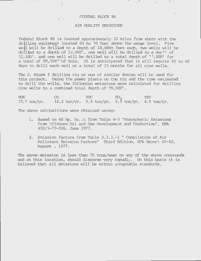
FEDERAL BLOCK 86 • I •
AIR OUALITY EMISSIONS
Federal Block 86 is located approximately 22 miles from shore with the dr i l l i n g equipment- located 60 to 70 feet above the water level. Five weii w i l l be d r i l l e d to a depth of 10,000+ feet eacjh, two wells w i l l be drilled to a depth of 12,000', one well w i l l be drilled to a der1-1- of 11,500', and one well w i l l be d r i l l e d to a tot a l depth of V ,000' for a total of 99,500'v'of hole. I t i s anticipated that i t w i l l recruire 45 to 60 days to d r i l l each well or a tot a l of 15 months for a l l nine wells.
The J. Storm I d r i l l i n g r i g or one of similar design w i l l be used for this project. Using the power plants on the r i g and the time estimated to d r i l l the wnlls, the following emissions were calculated for d r i l l i n g nine wells to a combined total depth of ?9,500'.
NOX CO VOC S02 TSP 73.7 ton/yr. 16.2 ton/yr. 5.9 ton/yr. 5.3 ton/yr. 4.9 ton/yr.
The above calcualtions were obtained using:
1. Based on 60 hp. hr, Lc from Table 4-3 "Atmospheric Emissions from Offshore Oil and Gas Development and Production", EPA 450/3-77-026, June 1977.
2. Emission factors from Table 3.3.3.-1 " Compilation of Air Pollutant Emission Factors" Third Edition, EPA Report: AP-42, August , 1977.
Ihe above emission is less than 75 tcns/uear on any of the above conpounds and at this location, should disperse very rapudly. On this basis i t is believed that a l l emissions w i l l be within acceptable standards.
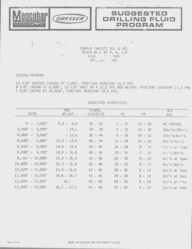
Moacobor (j&PESSER^) S U G G E S T E D
D R I L L I N G F L U I D P R O G R A M
CORPUS CHRISTI OIL & GA'S BLOCK 8F-L #1 N. W. 1/4
HIG U . .Af-: 'REA OFr ih j f t t ".XAS
CASING PROGRAM:
13 3/8" SURFACE CASING AT 3 ,000 ' , FRACTURE GRADIENT 14.4 PPG 9 5 /8 " CASING AT 8 , 8 0 0 ' , 12 1/4" HOLE OR A 12.5 PPG MUD WEIGHT, FRACTURE GKADIENT 17.3 PPG 7 5 / 8 " CASING AT 1 0 , 5 0 0 ' , FRACTURE GRADIENT 18.6 PPG
SUGGESTED PROPERTIES
FTTJD mm. m DEPTH WEIGHT VISCOSITY P V YP W/L
0' - 3,000' 8.8 - 9.0 45 - 50 b - 10 15 - 20 NO CONTROL 3,000' - 8,000' - 10.L 32 - 38 5 - 12 12 - 15 25cc's-12cc*i
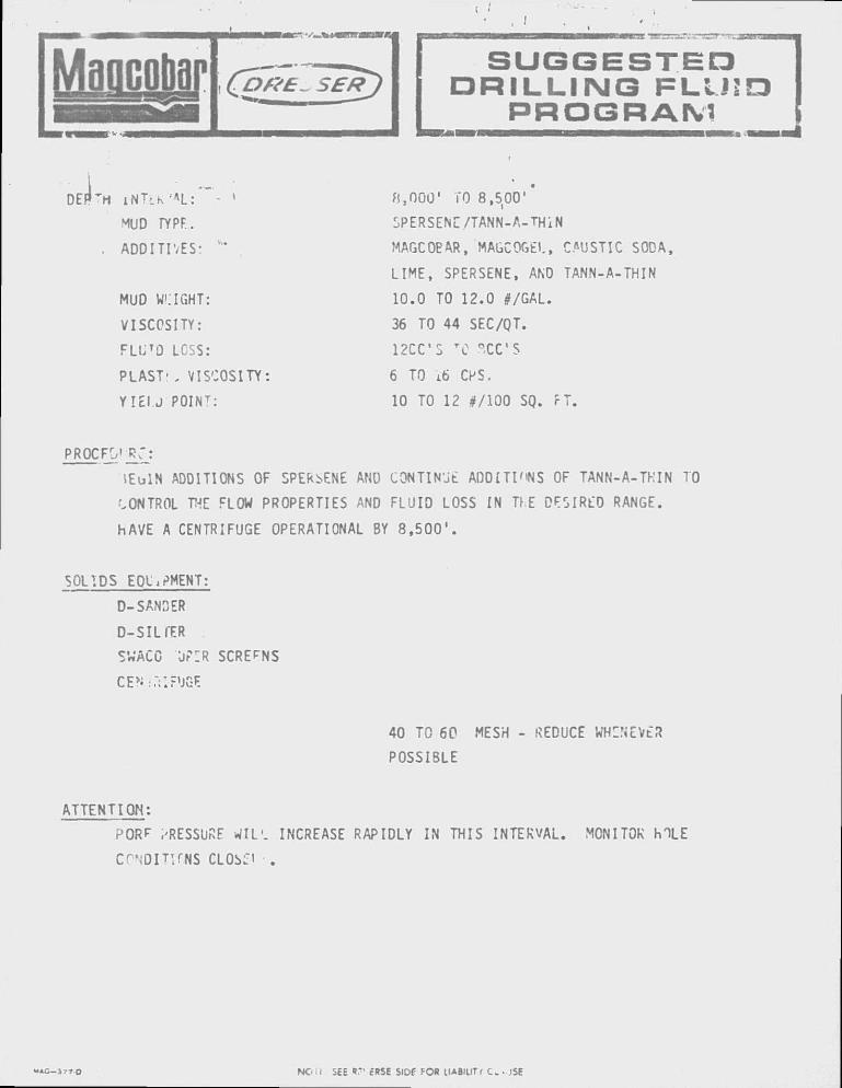
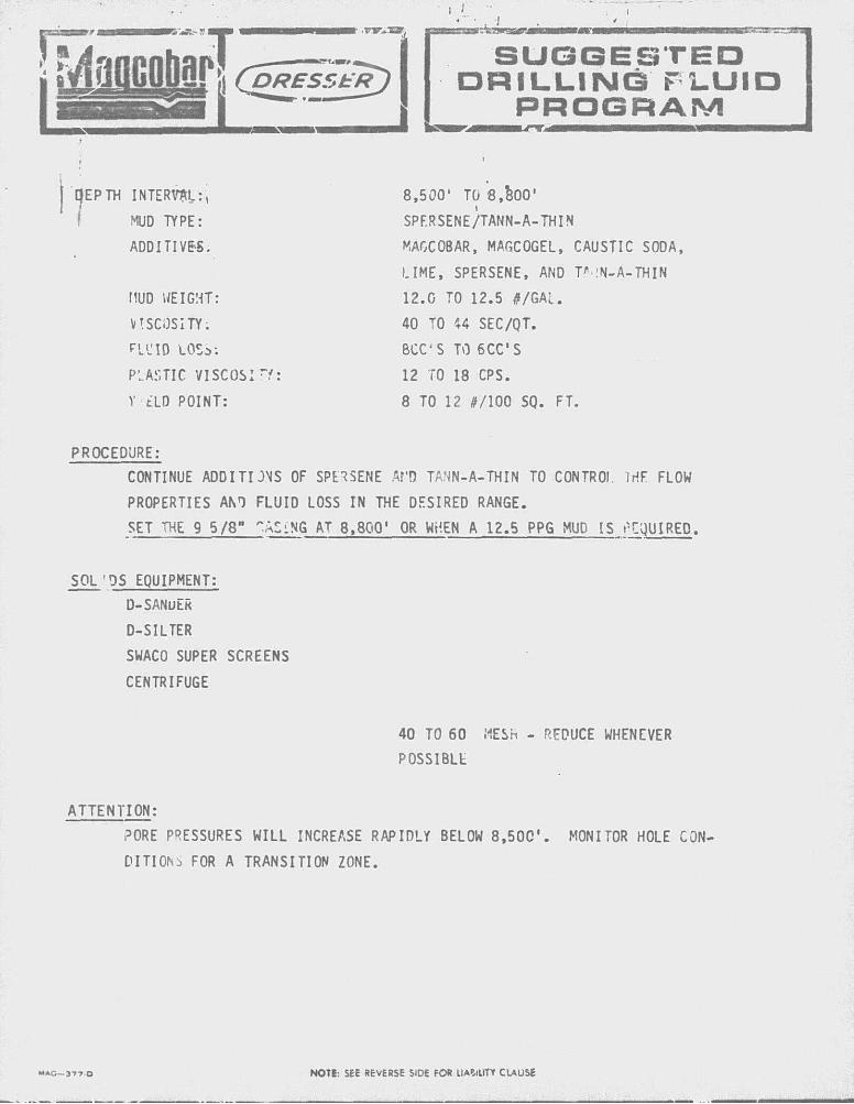
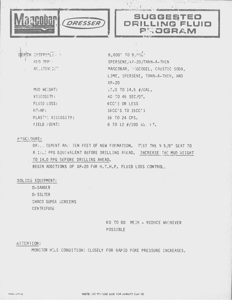
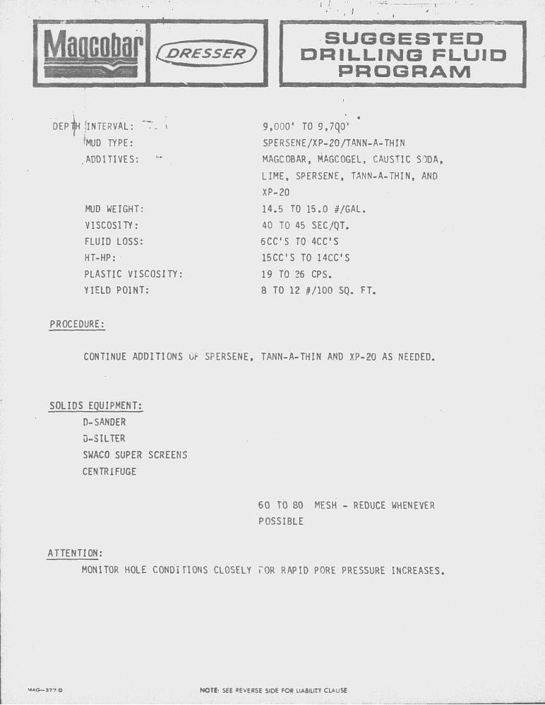
8,000' - 3,500' - 12.0 36 - 44 6 - 16 10 - 12 12cc's-8cc's 8,500' - 8,800 ! 12.0 - 12.5 40 - 44 12 - 18 18 - 12 8cc's-5cc :s 8,800' - 9,000* 14.0 - 14.5 40 - 45 16 - 24 8 - 12 r-(.c's or less 9,000' - 9,700' 14.5 - 15.0 40 - 45 19 - 25 8 - 12 6cc's-4cc's 9,/Ou' - 10,000* 15.0 - 15.3 42 - 46 22 - 30 8 - 12 4cc's or less
10,000' - 10,500' 15.3 - 15.9 42 - 46 24 - 32 8 - 12 4cc's-3cc's 10,500' - 11,000' 15.9 - 16.6 42 - 46 28 - 36 8 - 12 3cc's or less 11,000' - 12,000' 16.6 - 16.7 42 - 46 29 - 38 8 - 12 3cc's or less 12,000' - 13,000' 16.7 44 - 48 29 - 38 8 - 14 3cc's or ?««s 13,000' - 14,000' 16.7 - 17.1 44 - 48 30 - 40 8 - 14 3cc's or less
M A G — 3 7 7 O NOTE: SEE REVERSE SiDE FOR LIABILITY CLAUSE
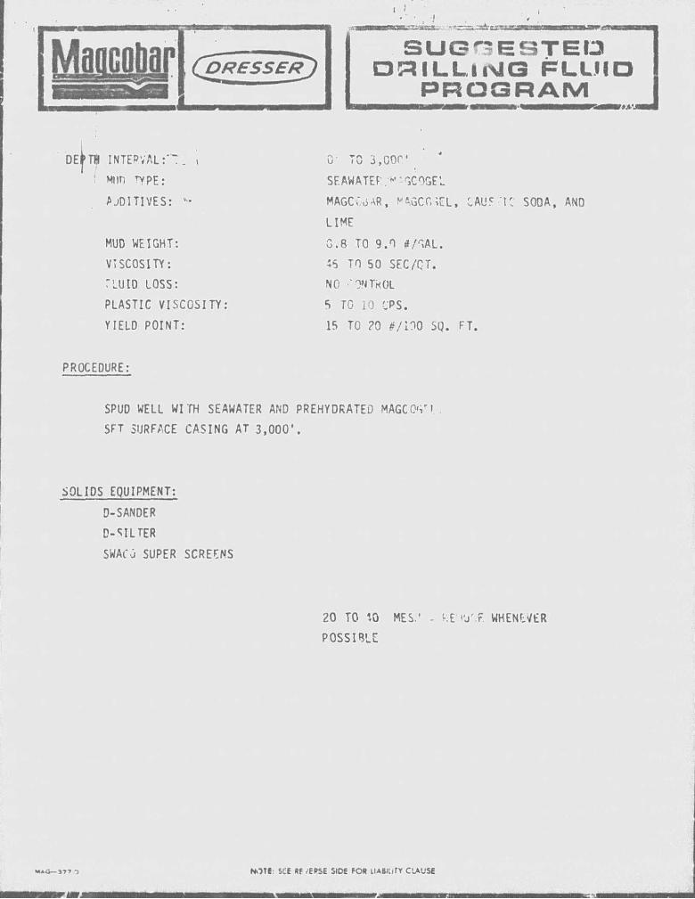
Maacotiapj
0- TO 3,COP'
SEAWATEF'' SCOGEL
MAGC.'oAR, PAGCGiEL, CAU5 'tC SOOA, ANO
LIME
G.8 TO 9.0 *r ,AL.
:S TO 50 SEC/QT.
NO 'ONTkOL
5 TO 10 CPS.
15 TO ?0 F/nO SQ. FT.
PROCEDURE:
SPUD WELL WITH SEAWATER AND PREHYDRATED MAGCO'vi
SFT SURFACE CASING AT 3,000*.
SOLIDS EQUIPMENT:
D-SANDER
D-SILTER
SWACO SUPER SCREENS
20 TO «.0 MES.* - KE I'J'.F. WHENEVER
POSSIBLE
S U G G E S T E D • a i L L i N G F L L . H
P R O G R A M
DE TB INTERVALi"". . i MI in rypE:
A JDITIVES:
MUD WEIGHT:
VISCOSITY:
TLUID LOSS:
PLASTIC VISCOSITY
YIELD POINT:
MAG— 37"» T NOTE: SCE Rf /EPSE SIDE FOR LIABILITY CLAUSE
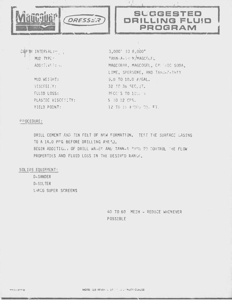
S U G G E S T E D D R I L L I N G F L U I D
P R O G R A M
DfiPTH INTERVAL:-
MUD TYPC-
MUD WEIGHT:
VISCOSI ."Y:
ADD'.T;vc " : v..
3,000' TO 8,000 '
TANN-A-'M N/MAGCOa.
MAGCOBARf MAGCOGEL, C': MIC S00A,
LIME, SPERSENE, AND TAN,:-/-IMP.'
9.0 TO 10.0 #/GAL.
32 T 0 3b SEC, .jT.
FLLID LOSS: 25CCS TO K V . *
PLASTIC V : S C C . C : T Y : 5 TO !2 CPS.
YIELD POINT: 12 TO lb J 'UMJ FT
PROCEDURE:
DRILL CEMENT ANO TEN FEtT OF NEW FORMATION. TEST T-iE SURFACE .ASING
TO A 14.0 P^G BEFORE ORILLING A4E*J.
BEGIN ADDI TIG;. , OF DRILL WA.EP ANL TANN-fi H^N TO CONTROL "HE FLOW
PROPERTIES AND FLUID LOSS IN THE DESIRrD RANGF.
SOLIDS EQUIPMENT-;
D-SANDER
D-SILTER
S .CO SUPER SCREENS
40 TO 60 MESH - REDUCE WHENEVER
POSSIBLE
NOT!: OfcE »EVE^ \ Sir " ..; . • •Mut t ClAUSE
MUD W!*IGHT:
VISCOSITY:
FLUTO LCSS:
PLASTI, VISCOSITY
Y I E U POINT:
Maocobar
DEF^rt I N T I K 'AL: - • 8
MUD TYPE. r J
. ADDITIVES' M
r_-:.:—r--
S U G G E S T E D D R I L L I N G F L U I D
P R O G R A M
LIME, SPERSENE, AND TANN-A-THIN
10.0 TO 12.0 #/GAL.
36 TO 44 SEC/QT.
12CCS T 0 "XC'S
6 TO L6 CPS.
10 TO 12 #/100 SQ. rT.
PROCFO' RT:
I E U I N ADDITIONS OF SPERSENE ANO CONTINUE A00ITI"NS OF TANN-A-THIN TO
'.ONTROL TT-iC FLOW PROPERTIES AND FLUID LOSS IN TFE DESIRED RANGE.
hAVE A CENTRIFUGE OPERATIONAL BY 8 , 5 0 0 ' .
SOLIDS EQLiPMENT:
D-SANDER
D-SILI'ER
SWACO UP:R
CENi.'tlr'JG^
SCREENS
40 TO 60 MESH - REDUCE WHINEVER POSSIBLE
ATTENTION:
PORF i-RESSUPvF WIL'. INCREASE RAPIDLY IN THIS INTERVAL. MONITOR h X E
C r \DITI fNS CLOSL'i .
MAC— 3 7 7 - 0 NOW SEE « n e'RSE SiDF FOR IIABHITI C . JSE
S U G G E S T E D D R I L L I N G F L U I D
P R O G R A M
EP TH INTERVAL: i
MUD TYPE:
8,500' TO 8.&00'
RA'ID LOSS:
riUD WEIGHT:
ADDITIV&S.
VISCOSITY:
SPERSENE/TANN-A-THIN
MAGCOBAR, MAGCOGEL, CAUSTIC SODA,
LIME, SPERSENE, AND T'-.'N-A-THIN
12.0 TO 12.5 #/GAL.
40 TO 44 SEC/QT.
BCC'S TO 6CCS
PLASTIC VISCOSI Pt: 12 TO 18 CPS.
V ELD POINT: 8 TO 12 1/100 SQ. FT.
PROCEDURE: CONTINUE ADDITIONS OF SPERSENE Af'D TANN-A-THIN TO CONTROI. IriF FLOW
PROPERTIES ANT FLUID LOSS IN THE DESIRED RANGE.
SET THE 9 5/8" "ASiNG AT 8,800' OR WHEN A 12.5 PPG MUD IS ACQUIRED.
SOL'PS EQUIPMENT:
D-SANuER
D-SILTER
SWACO SUPER SCREENS
CENTRIFUGE
PORE PRESSURES WILL INCREASE RAPIDLY BELOW 8,500'. MONITOR HOLE CON
DITION- FOR A TRANSITION ZONE.
40 TO 60 MESH - REDUCE WHENEVER
POSSIBLE
ATTENTION:
NOTE: SEE REVERSE SIDE FOR llA^illTr CLAUSE
CJEP!TH KM TYP'"'
AO-ITl VI-5:*" .
DRESSER
MUD WEIGHT:
VISCOSITY:
FLUID LOSS:
HT-HP:
PLASTIC VISCOSITY
HELD POINT:
S U G G E S T E D D R I L L I N G F L U I D
P R O G R A M
8,800' TO 9.000'
SPERSENE/XP-20/TANN-A-THIN
MAGCOBAR , ' \GC0GEL, CAUSTIC SODA,
LIME, SPERSENE, TANN-A-THIN, AND
XP-20
14.0 TO 14.5 #/GAL.
40 TO 45 SEC/QT.
6CCS OR LESS
16CCS TO 15CC S
16 TO 24 CPS.
8 TO 12 #/100 SO. rT.
P?OCi.DURE:
DR.. . CEMENT AND TEN FEET OF NEW FORMATION. TCST THE 9 5/8" SEAT TO
A l / .Z PPG EQUIVALENT BEFORE DRILLING AHEAD. INCREASE W MUD WEIGHT
• TO 14.0 PPG BEFORE DRILLING AHEAD.
BEGIN ADDITIONS OF XP-20 FOR H.T.H.P. FLUID LOSS CONTROL.
SOLIDS EQUIPMENT:
D-SANDER
D-SILTER
SWACO SUPER SCREENS
CENTRIFUGE
60 TO 80 MESH - REDUCE WHENEVER
POSSIBLE
ATTENTION:
MONITOR HCLE CONDITIONS CLOSELY FOR RAPID PORE PRESSURE INCREASES.
MAC— j 7 t a NOTE: i fE sev'KSE SiOE ?OR UABIUTY ClA'.SE
S U G G E S T E D D R I L L I N G F L U I D
P R O G R A M
DEPT[H ;INTERVAL: i
'MUD TYPE:
ADDITIVES: w '
MUD WEIGHT:
VISCOSITY:
FLUID LOSS:
HT-HP:
PLASTIC VISCOSITY
YIELD POINT:
9,000' TO 9,7q0''
SPERSENE/XP-20/TANN-A-THIN
MAGCOBAR, MAGCOGEL, CAUSTIC SODA,
LIME, SPERSENE, TANN-A-THIN, AND
XP-20
14.5 TO 15.0 #/GAL.
40 TO 45 SEC/QT.
6CCS TO 4CCS
15CCS TO 14CCS
19 TO 26 CPS.
8 TO 12 #/100 SQ. FT.
PROCEDURE:
CONTINUE ADDITIONS i> SPERSENE, TANN-A-THIN AND XP-20 AS NEEDED.
SOLIDS EQUIPMENT:
D-SANDER
D-SILTER
SWACO SUPER SCREENS
CENTRIFUGE
60 TO 80 MESH - REDUCE WHENEVER
POSSIBLE
ATTENTION:
MONITOR HOLE CONDITIONS CLOSELY FOR RAPID PORE PRESSURE INCREASES.
M A C — 3 7 7 . 0 NOTE: SEE REVERSE SIDE FOR LIABILITY CLAUSE
MaQcotiar S U G G E S T E D D R I L L I N G F L U I D
P R O G R A M
DEPTVi .INTERVAL:
MUD TYPE:
ADDITIVES:
• - t
MUD WEIGHT:
VISCOSITY:
FLUID LOSS:
HT-HP:
PLASTIC VISCOSITY
YIELD POINT:
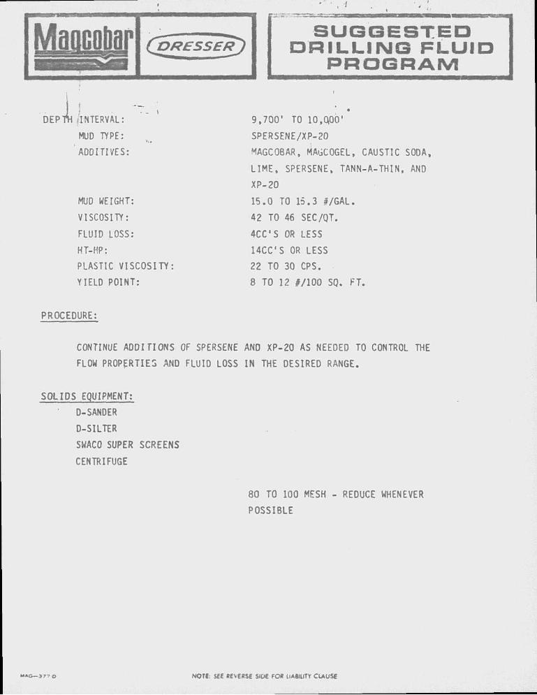
9,700' TO 10,0100'
SPERSENE/XP-20
MAGCOBAR, MAGCOGEL, CAUSTIC SODA,
LIME, SPERSENE, TANN-A-THIN, AND
XP-20
15.0 TO 15.3 #/GAL.
42 TO 46 SEC/QT.
4CCS OR LESS
14CCS OR LESS
22 TO 30 CPS.
8 TO 12 #/100 SQ. FT.
PROCEDURE:
CONTINUE ADDITIONS OF SPERSENE AND XP-20 AS NEEDED TO CONTROL THE
FLOW PROPERTIES AND FLUID LOSS IN THE DESIRED RANGE.
SOLIDS EQUIPMENT:
D-SANDER
D-SILTER
SWACO SUPER SCREENS
CENTRIFUGE
80 TO 100 MESH - REDUCE WHENEVER
POSSIBLE
M A G — 3 7 7 O NOU. SEE REVERSE 5I0£ FOR UAglUTr CLAUSE
I J
Mflflcotoy1
• ••••in nim
S U G G E S T E D D R I L L I N G F L U I D
P R O G R A M
DEPpi' INTERVAL:
(MUD TYPE:
ADDITIVES: -
MUD WEIGHT:
VISCOSITY:
FLUID LOSS:
HT-HP:
PLASTIC VISCOSITY
YIELD POINT:
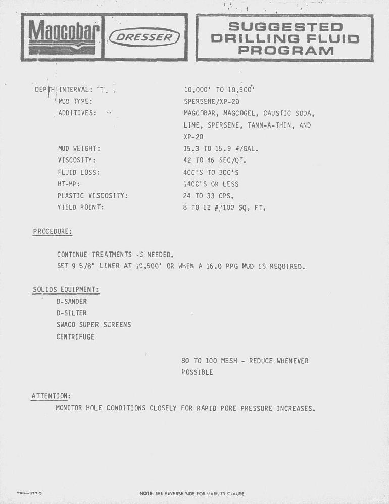
10,000' TO 10,900'
SPERSENE/XP-20
MAGCOBAR, MAGCOGEL, CAUSTIC SODA,
LIME, SPERSENE, TANN-A-THIN, AND
XP-20
15.3 TO 15.9 #/GAL.
42 TO 46 SEC/QT.
4CCS TO 3CCS
HCC'S OR LESS
24 TO 33 CPS.
8 TO 12 #/100 SQ, FT.
PROCEDURE:
CONTINUE TREATMENTS sS NEEDED.
SET 9 5/8" LINER AT 10,500' OR WHEN A 16.0 PPG MUD IS REQUIRED.
SOLIDS EQUIPMENT:
D-SANDER
D-SILTER
SWACO SUPER SCREENS
CENTRIFUGE
80 TO 100 MESH - REDUCE WHENEVER
POSSIBLE
ATTENTION:
MONITOR HOLE CONDITIONS CLOSELY FOR RAPID PORE PRESSURE INCREASES.
NOT1-. SEE REVERSE SIDE FOR UABIUTY CLAUSE
Maflciaj" Maflciaj" ^ ^ ^ ^ ^ ^ ^ ^ ^ ^
(jDRESSER^) 1 S U G G E S T E D
D R I L L I N G F L U I D P R O G R A M
DQPTH INTERVAL:
MUD TYPE:
ADDITIVES:
MUD WEIGHT:
VISCOSITY:
FLUID LOSS:
HT-HP:
PLASTIC VISCOSITY
YIELD POINT:
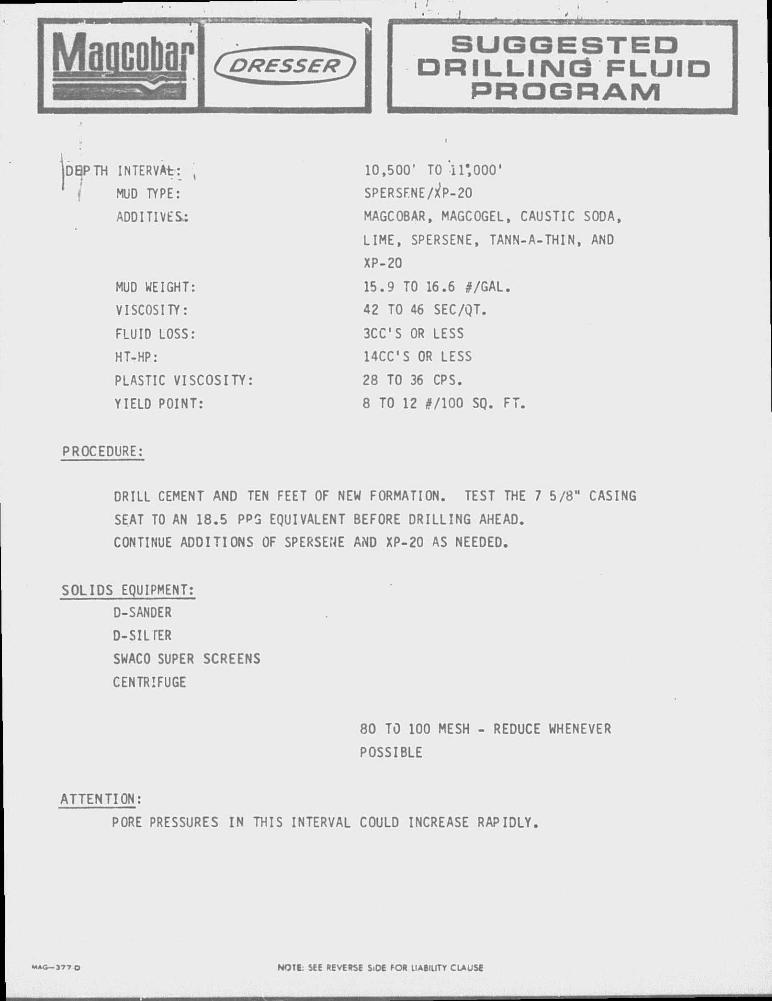
10,500' TO i l ' ,000'
SPERSFNE/ P-20
MAGCOBAR, MAGCOGEL, CAUSTIC SODA,
LIME, SPERSENE, TANN-A-THIN, AND
XP-20
15.9 TO 16.6 #/GAL.
42 TO 46 SEC/QT.
3CC S OR LESS
14CCS OR LESS
28 TO 36 CPS.
8 TO 12 #/100 SQ. FT.
PROCEDURE:
DRILL CEMENT AND TEN FEET OF NEW FORMATION. TEST THE 7 5/8" CASING
SEAT TO AN 18.5 PPG EQUIVALENT BEFORE DRILLING AHEAD.
CONTINUE ADDITIONS OF SPERSENE AND XP-20 AS NEEDED.
SOLIDS EQUIPMENT:
D-SANDER
D-SIL TER
SWACO SUPER
CENTRIFUGE
SCREENS
80 TO 100 MESH - REDUCE WHENEVER
POSSIBLE
ATTENTION: PORE PRESSURES IN THIS INTERVAL COULD INCREASE RAPIDLY.
M A G - J 7 7 O NOTE: SEE REVERSE S.DE fOR LIABILITY CLAUSE
Maocojijjf • • , I
S U G G E S T E D • R I L L I N G F L U I D
P R O G R A M
DEPTH INTtRVAL:
MUD TVPE:
ADDITIVES:
MUD WEIGHT:
VISCOSITY:
FLUID LOSS:
HT-HP:
PLASTIC VISCOSITY:
YIELD POINT:
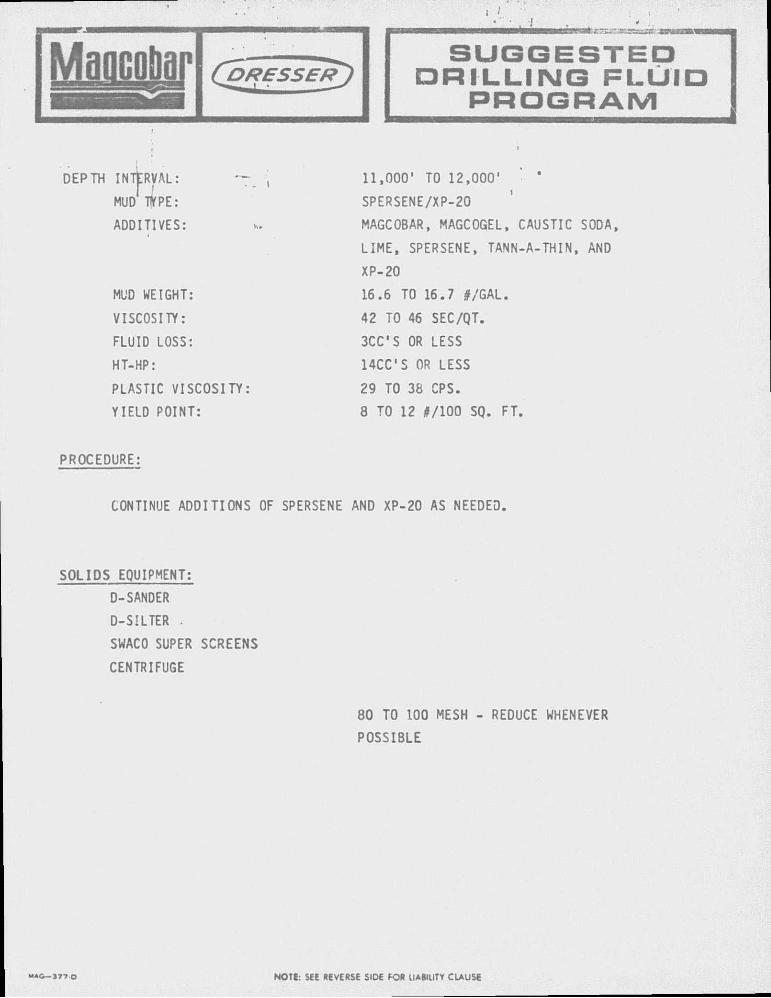
11,000' TO 12,000'
SPERSENE/XP-20
MAGCOBAR, MAGCOGEL, CAUSTIC SODA,
LIME, SPERSENE, TANN-A-THIN, AND
XP-20
16.6 TO 16.7 #/GAL.
42 TO 46 SEC/QT.
3CCS OR LESS
14CCS OR LESS
29 TO 38 CPS.
8 TO 12 #/100 SQ. FT.
PROCEDURE:
CONTINUE ADDITIONS OF SPERSENE AND XP-20 AS NEEDED,
SOLIDS EQUIPMENT:
D-SANDER
D-SILTER .
SWACO SUPER SCREENS
CENTRIFUGE
80 TO 100 MESH - REDUCE WHENEVER
POSSIBLE
M A G — 3 7 7 Q NOTE: SEE REVERSE SIDE FOR UABIUTY CLAUSE
MaflcoDgp S U G G E S T E D D R I L L I N G F L U I D
P R O G R A M
DEPTH INTERVAL:
MUD TYPE:
ADDITIVES:
MUD WEIGHT:
VISCOSITY:
FLUID LOSS:
HT-HP:
PLASTIC VISCOSITY:
YIELD POINT:
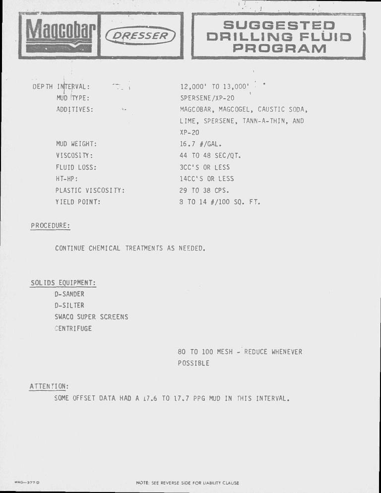
12,000' TO 13,000'
SPERSENE/XP-20
MAGCOBAR, MAGCOGEL, CAUSTIC SODA,
LIME, SPERSENE, TANN-A-THIN, AND
XP-20
16.7 #/GAL.
44 TO 48 SEC/QT.
3CCS OR LESS
14CCS OR LESS
29 TO 38 CPS.
8 TO 14 #/100 SQ. FT.
PROCEDURE:
CONTINUE CHEMICAL TREATMENTS AS NEEDED.
SOLIDS EQUIPMENT:
D-SANDER
D-SILTER
SWACO SUPER SCREENS
CENTRIFUGE
80 TO 100 MESH - REDUCE WHENEVER
POSSIBLE
ATTENTION:
SOME OFFSET DATA HAD A i7.6 TO 17.7 PPG MUD IN THIS INTERVAL.
" * 0 — J 7 T O NOTE: SEE REVERSE SIDE FOR IIABIIITY CLAUSE
Magcobar ( D R E S S E R )
wwnHr rTn
T". MCBBB 'TA\A^L
S U G G E S T E D D R I L L I N G P L U I I
P R O G R A M
DEPTji INTERVAL:
MUD TYPE:
ADDITIVES:
MUD WEIGHT:
VISCOSITY:
FLUID LOSS:
HT-HP:
PLASTIC VISCOSITY
YIELD POINT:
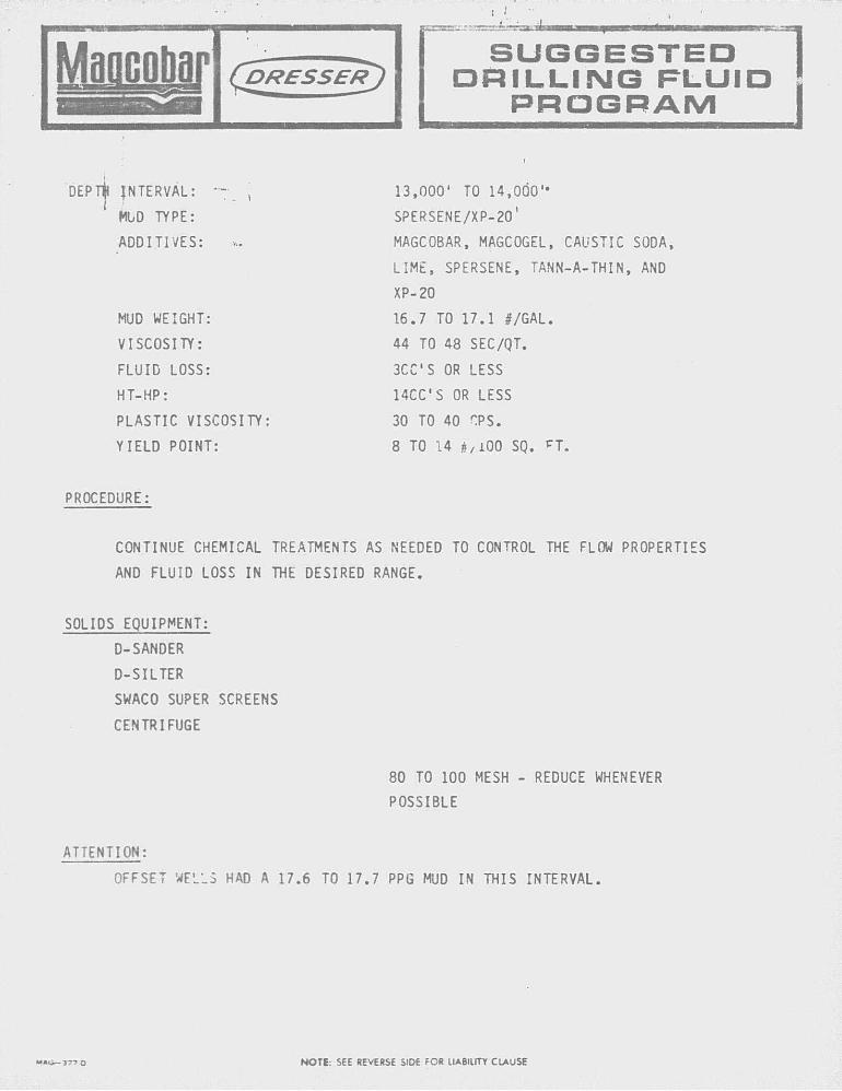
13,000' TO 14,000"
SPERSENE/XP-20'
MAGCOBAR, MAGCOGEL, CAUSTIC SODA,
LIME, SPERSENE, TANN-A-THIN, AND
XP-20
16.7 TO 17.1 #/GAL.
44 TO 48 SEC/QT.
3CCS OR LESS
14CCS OR LESS
30 TO 40 r.PS.
8 TO 14 jj/lOO SQ. PT.
PROCEDURE:
CONTINUE CHEMICAL TREATMENTS AS NEEDED TO CONTROL THE FLOW PROPERTIES
AND FLUID LOSS IN THE DESIRED RANGE.
SOLIDS EQUIPMENT:
D-SANDER
D-SILTER
SWACO SUPER SCREENS
CENTRIFUGE
80 TO 100 MESH - REDUCE WHENEVER
POSSIBLE
ATTENTION:
OFFSET WELL5 HAD A 17.6 TO 17.7 PPG MUD IN THIS INTERVAL.
M » v i - 3 7 7 O NOTE: 5EE REVERSE SIDE FOR LIABILITY CLAUSE
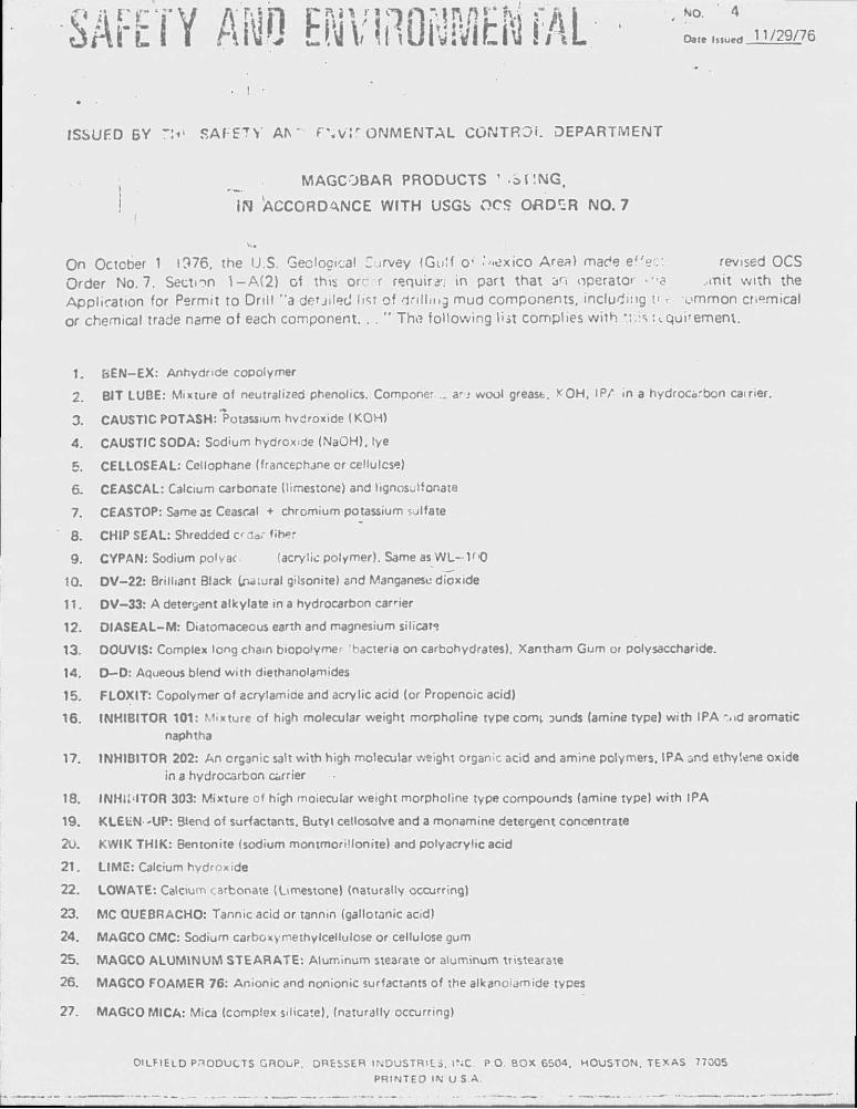
SArETY AISO ENVIilONMEti fAL NO. 4
Date i.«u.H H /29 /76
• I •
ISSUED BY T\i* SAFETY Al \ ' f ' W ' i r O N M E N T A L CONTROL DEPARTMENT
( _ MAGCOBAR PRODUCTS ' o f ' . N G ,
IN 'ACCORDANCE WITH USGS OCS O f l D S R N O . 7
On October 1 1976, the U.S. Geological Z ^rvey (Gulf o- "'-exico Area) made ef 'ec: revised OCS Order No.7 . Section 1 - A ( 2 ) o l this or - r requ i re in part that an operator - o ,mi t w i th the Appl icat ion for Permit to Dri l l "a detjilecJ lisl of dri l l ing mud components, including t< t v m m o n cr.pmical or chemical trade name of each component. . . " The fol lowing list complies w i th •.f.ls u q u i ' e m e n i .
1. BEN-EX: Anhydride copolymer
2. BIT LUBE: Mixture of neutralized phenolics. Compone: _ ar-j wool greast. *OH. IP/ in a hydrocarbon cairier.
3. CAUSTIC POTASH: Potassium hydroxide (KOH)
4. CAUSTIC SODA: Sodium hydroxide (NaOH). lye
5. CELLOSEAL: Cellophane (francephjne or cellulose)
6. CEASCAL: Calcium carbonate (limestone) and lignosulfonate
7. CEASTOP: Sameas Ceascal + chromium potassium sulfate
8. CHIP SEAL: Shredded a dar fiber
9. CYPAN: Sodium polyac (acrylic polymer). Same as WL- 1' '0
10. DV-22: Brilliant Black Inaiural gilsonite) and Manganese dioxide
11. DV-33: A detergent alkylate in a hydrocarbon earner
12. DIASEAL-M: Diatomaceous earth and magnesium silicate
13. DOUVIS: Complex long chain biopolyme' Hacteria on carbohydrates), Xantham Gum or polysaccharide.
14. D—D: Aqueous blend with diethanolamides
15. FLOXIT: Copolymer of acrylamiae and acrylic acid (or Propenoic acid)
16. INHIBITOR 101: Mixture of high molecular weight morpholine type conn Dunds (amine type) with IPA -..id aromatic naphtha
17. INHIBITOR 202: An organic salt with high molecular weight organic acid and amine polymers. IPA jnd ethylene oxide
in a hydrocarbon carrier
18. INHlMTOR 303: Mixture of high moiccular weight morpholine type compounds (amine type) with IPA
19. KLEEN-UP: Blend of surfactants. Butyl cellosorve and a monamine detergent concentrate
2U. KWIK THIK: Bentonite (sodium montmorillonite) and polyacrylic acid
21 . LIME: Calcium hydroxide
22. LOWATE: Calcium carbonate (Limestone) (naturally occurring)
23. MC QUEBRACHO: Tannic acid or tannin (gallotanic acid)
24. M A G C O CMC: Sodium carboxymethylcellulose or cellulose gum
25. MAGCO ALUMINUM STEARATE: Aluminum stearate or aluminum tristearate
26. MAGCO FOAMER 76: Anionic and nonionic surfactants of the alkanoiamide types
27. MAGCO MICA: Mica (complex silicate), (naturally occurring)
OILFIELD PRODUCTS GROUP. DRESSER INDUSTRILS. INC P.O. BOX 6504, HOUSTON. TEXAS 77005
PRINTED IN U S A .
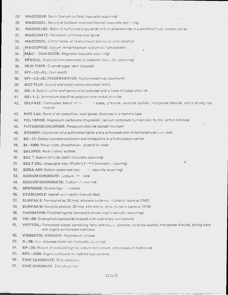
28. MAGCOBAR: Bar-i* (barium sulfate) (naturally occurring)
29. MAGCOGEL: Bentonite (sodium montmoril lonite) (naturally oce. ring)
30. MAGCOLUBE: Blend of suifur ized triglyceride and i n alkanolamide in a paraffinic hydr - carbon carrier
3 1 . MAGCONATE: Petroleum sulfonate and lignite
32. MAGCONOL: 2-ethyl hexar ol (2-ethyihexyl a.'cchol or octyl alcohol) ,
33. i MAGCOPHOS: Sodium tetraphosphate (sodium pe'vphosphate)
34. JMAGr SIUM OXIDE: Magnesia (naturally occurring) (
35. M i x i C A L : Sized calcium carbonate (Limestone) (naturallv occurring)
36. M U D FIBER: Crushe* sugar cane (bagasse)
37. M Y - L O - J E L : Corn starch
38. M Y - L O - J E L PRESERVATIVE: Paraformaldehyde (paraform)
39. N U T PLUG: Ground and sized walnut and pecan shells
40. OS—1: Sodium sulfite and tannic acid catalyzed wi th a trace of cobalt chlor de
4 1 . O S — 1 - L : Ammonium bisu l f i te catalyzed wi th nickel chloride
42. O I L F A Z E : Formulated b lend of fc i soaps, g ; lsonite, oxidized asohalt, manganese dioxide, and a drying clay
material
43. PIPE LAX: Blend of an oxazol ine, wool grease, dispersea in a naphtha base
44. POLYBRINE: Magnesium carbonate (magnesite). calcium carbonate (Limestone), hydro, yethyl cellulose
45. POTASSIUM CHLORIDE: Potassium chloride (potash muriate!
46. RESINEX: Copolymer of a sulfonated lignite and a sulfonated phenol-formaldehyde u. e i resin
47. S £ — 1 1 : Dodecyl benzene sulfonate and imidazoline in a hydrocarbon carrier
48. S1--1000: Polvacrylate, phosthonat? glycerol in water
49. S A L I N E X : Alcohol ether sulfate
50. S A L T : Sodium chloride (salt) {naturally occurring)
5 1 . S A L T GEL: Attapulgite clay (Fuller's F , , t K ) (naturally < ccurring) '
52. S O D A ASH: Sodium carbonate (soc • it .naturally occurring)
53. S O D I U M CHROMATE: Sod ium h- mate
54. S O D I U M DICHROMATE: Sodium d .nromate
5&. SPERSENE: Chrome lign n.'onate
56. S T A 8 I L H 0 L E : Asphalt ano kaol in (natural clay)
57. S U R F A K E: Formulated as 3 0 moi . ethylene oxide noi ' I phenol (same as DME)
58. S U R F A K M: Nonionic phenol ; 30 moi. ethylene ov de surfactants (same a: QMS)
59. T A N N A T H I N : Oxidized l igni te (leonardite brown coal) (naturally occurring)
60. VG—69: Onanophylic benton i te (treated wi th quaternary ammonium)
6 1 . V E R T O I L : Formulated b lend containing fatty acid scu^s. gilsonite, oxidized asphalt, manganese dioxide, drying clays
with organic sul fonated stabilizers
62. VISBESTOS, VISQUICK: Magnesium silicates
63. X—38: Iron carbonate (siderite) (naturally occurring)
64. XP—20: Mixture of oxidized l igni te, sodium dichromate, and potassium hydroxide
65. XPK—2000: Organic sulfonate in naphtha base solvents
66. Z I N C CARBONATE: Zinc carbenau
67. Z I N C CHROMATE: Zinc chromate
Q Q Q
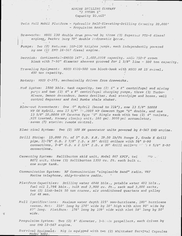
MARINE DRILLING COMPANY -J STORM I "
Capaci ty 23,OCO' • l •
Twin Hull Mobil Platform - Hydraulic Self-Elevating-Drilling Caoacity 20,000' - Propulsion Assist
Drawworks: NSCC 130 double druir, pow^ed by three (3) Superior PTD-8 diesel engines^. Par koi burg 70" double rvdromatic br?xe.
1 ' - ' Pumps: Two (2) Nat+jna i 10P-130 triplex pumps, each independently powered
by one (1) EMD 16-567 diesel engine.
Derrick: Continents1-EMSCO 147', 1,400,0008 capacity, ASCO 750-F crown block with 7-50" diameter sheaves grooved for 1 3/8" line - 500 ton capacity.
Traveling Equipment: NSCO 650G-500 ton block-hook with NSCO N8 15 swivel, 450 ton capacity. j
Rotary: NSCO C-375, mechaniaally driven from drawworks.
Mud System: 1500 bbls. tank capacity, two (2) 6" x 8" centrifugal mud mixing pu^pz and two (2) 6" x 8" centrifugal charging pumps, three (3) Turbo-Mixers, Demco desanders, Demco desilter, dual standpipe and hoses, well control degasser and dual Rumba shale shaker.
Blow-out Preventers: One .'0" Hydril (bored to 21k"), one 13 5/8" 50008 WP GK Hydril, one 13 5/Q" VJ,0009 WP Cameron Type "U" double, and one 13 5/8" 10,0008 WP Caneron Type "U" Single eacb witb two (2) 4" outlets/
^H2S treated, Koomey closing unit, 160 gal . 3000 psi accumulator, seven (7) station remote coitrol.
Elec rical Svstem: Two (2) 500 KW generator units powered by 8-567 EMD engine.
D r i l l S t r i n g : 15 ,000 f t . o f 5" O.D. X . H . 19.50 l b / f t Range 2 , Grade E d r i l l p i p e , 21-7h" O.D. 2 7/8" I . D . x 3 0 ' d r i l l c o l l a r s w i t h 5h" H-90 connect ions , 2 -8" O.D. x 2 3 /4" I . D . x 30 ' d r i l l c o l l a r s •-" h 6 5 /8" E-90 connections .
Cement ing System: H a l l i b u r t o n s k i d u n i t . Model 867 KPCF, t w i 1f>0 . 8071 unit, three (3) Halliburton 1350 cu. f t . each bulk t . one surge tank.
Communication System: RF Communication "singleside Band" radio, VHF Marine telephone, ship-to-shore radio.
Platform Capacities: Drilling water 4848 bbls., potable water 402 bbls., fuel oil 1,796 bbls., bulk mud 3,900 cu. f t . , sack mud 3,000 sacks, two (2) link-belt 50 ton cranes, air conditioned quarters and galley for 48 men.
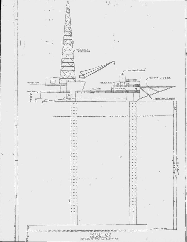
Hull Specifications: Maximum water depth 225' non-hurricane, 180' hurricane season, Mat: 210' long by 170' wide by 10' high with slot 90' wide by 87' long. Platforn.: 176' long by 109' wide with slot 58' long by 50' wide.
Propulsion System: Two (2) 8' diameter, 3-b- ade propel .7. e rs , each driven by one EMD 12-567 engine.
Survival Equipment: Rig is equipped with two (2) Whittaker Survival Capsules Model 9091.
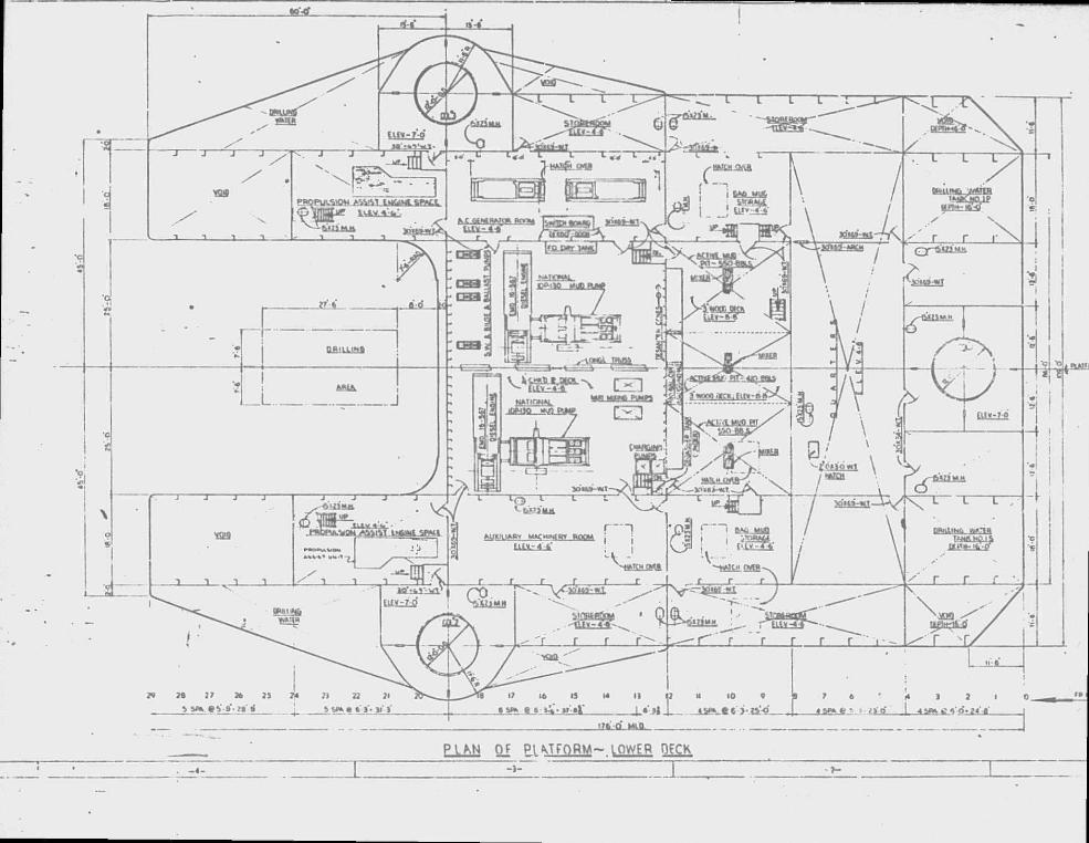
P I U * Of Pl MFQRM~ LOWER OtCK