Embed Size (px)
Citation preview

FIRE DEPARTMENT ● CITY OF NEW YORK
STUDY MATERIAL FOR
THE CERTIFICATE OF LICENSE EXAMINATION W-16 FOR
MOTOR FUEL STORAGE AND DISPENSING SYSTEM
© 10 /2011 New York City Fire Department - All rights reserved ®
A
CONTENT NOTICE OF EXAMINATION...................................................................................... I APPLICATION FORM................................................................................................ III STUDY MATERIAL AND TEST DESCRIPTION............................................... VI FIRE STATISTICS AND FACTS.............................................................................. 1 PART 1. DOCUMENTS, PERMIT, AND CERTIFICATE OF LICENSE ...... 2
1.1 Design and Installation Documents ................................................... 2 1.2 Permit .............................................................................................................. 2 1.3 Action and Time Periods on Application ......................................... 3 1.4 Certificate of License and Certificate of Fitness ......................... 3
1.4.1 W-16 Certificate of License ................................................................ 3 1.4.2 P-15 Certificate of Fitness .................................................................. 3
1.5 Approval and Inspections........................................................................ 4 1.6 Related Regulations................................................................................... 5
PART 2. DEFINITIONS .............................................................................................. 6 PART 3. GENERAL REQUIREMENTS.................................................................. 9
3.1 Piping, Valves, Fittings and Ancillary Equipment ....................... 9 3.1.1 Materials and testing ........................................................................... 9 3.1.2 Protections............................................................................................... 9 3.1.3 Overfill and backflow prevention ................................................... 10 3.1.4 Connections, joints and bends ....................................................... 12 3.1.5 Tank vents and opening ................................................................... 13 3.1.6 Filling pipes........................................................................................... 15
3.2 Labeling and Signage............................................................................... 15 3.2.1 Color coding and symbols of fill ports.......................................... 15 3.2.2 Warning signs....................................................................................... 16
PART 4. UNDERGROUND LIQUID MOTOR FUEL STORAGE TANK ..... 18 4.1 Tank Contents and Capacity Limitations...................................... 18 4.2 Design and Constructions of the Tanks ......................................... 18
4.2.1 General requirements ........................................................................ 18 4.2.2 Cathodically protected steel tanks ................................................ 18 4.2.3 Coatings ................................................................................................. 20
4.3 Location ........................................................................................................ 20 4.4 Leak Detection ........................................................................................... 21 4.5 Installation of Underground Tank and Piping Systems........... 24
4.5.1 Safety requirements during excavation operations ................. 24 4.5.2 Pouring concrete and backfilling ................................................... 25 4.5.3 Preparation for installation.............................................................. 26 4.5.4 Installation of underground tank and piping systems ........... 27
4.6 Monitoring, Inspection and Testing ................................................. 29 4.6.1 Monitoring at new underground storage tanks ........................ 29 4.6.2 Periodic Maintenance Requirements. ........................................... 30 4.6.3 Initial tank test .................................................................................... 31 4.6.4 Initial piping test ................................................................................. 31 4.6.5 Leak detection functionality test.................................................... 32 4.6.6 Fire extinguishing system test........................................................ 34

B
4.6.7 Emergency tank and piping system test ..................................... 34 4.6.8 Periodic tank and piping test .......................................................... 34
PART 5. ABOVEGROUND LIQUID MOTOR FUEL STORAGE TANK...... 35 5.1 Contents and Tank Capacities Limitation .................................... 35 5.2 Design and Constructions of Motor Fuel Tank Installations 35 5.3 Location Requirements .......................................................................... 36
5.3.1 Locations................................................................................................ 36 5.3.2 Protection............................................................................................... 36
5.4 Drainage Control, Diking and Secondary Containment .......... 37 5.4.1 Diked areas ........................................................................................... 38 5.4.2 Secondary containment system for aboveground tanks ........ 38
PART 6. FUEL-DISPENSING SYSTEM AND AREA ....................................... 40 6.1 Location of Dispensing Devices ......................................................... 40
6.1.1 Outdoor dispensing devices............................................................. 40 6.1.2 Indoor dispensing devices ................................................................ 40
6.2 Fuel-Dispensing Systems ...................................................................... 40 6.2.1 Fixed pumps required ....................................................................... 40 6.2.2 Mounting of dispensers..................................................................... 40 6.2.3 Dispenser emergency valve.............................................................. 41 6.2.4 Dispenser hose..................................................................................... 41 6.2.5 Fuel delivery nozzles .......................................................................... 42 6.2.6 Vapor-balance systems ..................................................................... 43 6.2.7 Emergency disconnect switches..................................................... 43
6.3 Supervision of the Dispensing of Liquid Motor Fuel ................ 44 6.3.1 Self-service motor fuel-dispensing facilities ............................... 44 6.3.2 Full service motor fuel-dispensing facilities............................... 45
PART 7. RECORD, MAINTENANCE AND REPORT ...................................... 46 7.1 Inventory Control for Underground Tanks.................................... 46
Example of the maintenance log book ......................................................... 47 7.2 Inspections and Tests Records ........................................................... 48 7.3 Equipment Maintenance ....................................................................... 48 7.4 Reporting of Spills and Discharges ................................................... 48
PART 8. RECONDITIONING, REPAIR AND OUT OF SERVICE TANKS49 8.1 Reconditioning an Underground Steel Tank ................................ 49
8.1.1 Manufacturer's guarantee................................................................ 49 8.1.2 Structural requirements ................................................................... 49 8.1.3 Preparation of tank interior ............................................................. 49 8.1.4 Coating (lining) specifications ......................................................... 50 8.1.5 Application of coating ........................................................................ 50 8.1.6 Tank closings........................................................................................ 50 8.1.7 Tank tightness testing ....................................................................... 50
8.2 Repair or Alteration of Tanks and Piping ...................................... 50 8.2.1 Cleaning of tank prior to repair...................................................... 51 8.2.2 Coating (lining) specifications ......................................................... 51 8.2.3 Inspection of coating .......................................................................... 51
8.3 Out of Service Tanks ............................................................................... 52

C
8.3.1 Underground out of service tanks ................................................. 52 8.3.2 Aboveground out of service tanks ................................................. 52
8.4 Removal of Tanks ..................................................................................... 53 PART 9. EMERGENCY PLAN AND FIRE CONTROL .................................... 54
9.1 Control of Ignition, Brush and Debris ............................................. 54 9.2 Fire Extinguishers .................................................................................... 54
9.2.1 Different types of fire extinguishers.............................................. 55 9.2.2 Fire extinguisher inspections.......................................................... 56
9.3 Fire Extinguishing System ................................................................... 57 APPENDIX A. STAGE II VAPOR COLLECTION DECOMMISIONING ..... 59 APPENDIX B. FIRE CODE CHAPTER 9 ............................................................ 61
FC 901 General........................................................................................................ 61 FC 902 Definitions.................................................................................................. 66 FC 904 Fire Extinguishing Systems ................................................................. 68 FC 906 Portable Fire Extinguishers ................................................................. 80
APPENDIX C. FIRE CODE CHAPTER 22 ......................................................... 85 FC 2201 General ..................................................................................................... 85 FC 2202 Definitions .............................................................................................. 86 FC 2203 Automotive liquid motor fuel-dispensing facility location of
dispensing devices ............................................................................................ 87 FC 2204 Automotive Liquid Motor Fuel-Dispensing Facility Dispensing
Operations ........................................................................................................... 88 FC 2205 Automotive Liquid Motor Fuel-Dispensing Facility Operational
and Maintenance Requirements .................................................................. 91 FC 2206 Automotive Liquid Motor Fuel-Dispensing Facilities Design
and Installation Requirements ..................................................................... 92 FC 2210 Marine Liquid Motor Fuel-Dispensing Facilities....................... 103 FC 2211 Repair Garages..................................................................................... 105
APPENDIX D. FIRE CODE CHAPTER 34 ....................................................... 109 FC 3401 General ................................................................................................... 109 FC 3402 Definitions ............................................................................................. 110 FC 3403 General Requirements....................................................................... 111 FC 3404 Storage.................................................................................................... 117 FC 3406 Special Operations.............................................................................. 144
APPENDIX E. FIRE RULE CHAPTER 22 ........................................................ 163 Rule Section § 2204-01....................................................................................... 163 Rule Section § 2205-01....................................................................................... 164 Rule Section § 2206-01....................................................................................... 164 Rule Section § 2206-02....................................................................................... 166 Rule Section § 2211-01....................................................................................... 168
APPENDIX F. FIRE RULE CHAPTER 34 ........................................................ 169 Rule Section § 3404-01....................................................................................... 169 Rule Section § 3404-02....................................................................................... 170 Rule Section § 3404-03....................................................................................... 172
APPENDIX G. FIRE RULE CHAPTER 48........................................................ 175 Rule Section § 4802-01....................................................................................... 175

D
Former Fire Department Rule 3 RCNY §21-14 ....................................... 176 Former Administrative Code §27-4066...................................................... 183 Former Administrative Code §27-4227...................................................... 183 Former Administrative Code §27-4055...................................................... 184 Former Administrative Code §27-4053...................................................... 185 Former Fire Department Rule 3 RCNY §21-06 ....................................... 187 Former Fire Department Rule 3 RCNY §21-17 ....................................... 187
I
NOTICE OF EXAMINATION
Requirements for Obtaining Certificate of License to Install, Alter, Test or Repair
of Automotive and Marine Liquid Motor Fuel Storage and Dispensing Systems and Flammable Liquid and Combustible Liquids Storage System (W-16)
Possession of a Certificate of License ("COL") is required by the New York City Fire Prevention Code (Chapter 4 of Title 27 of the New York City Administrative Code) in order to install, alter, test, and repair storage tanks and dispensing systems for flammable motor fuel (gasoline) or combustible motor fuel (diesel). In order to obtain a COL, you must submit proof that you meet the requirements listed below, and you must pass the Department's written examination. You may not take the examination until after the satisfactory review of your submissions. You may submit your application and the accompanying submissions by mail or in person to: New York City Fire Department, Attention: COL Review, Bureau of Fire Prevention, 9 MetroTech Center - 1st Floor, Brooklyn, New York, 11201-3857. If you have any questions, please contact (718) 999-2473. PRE-EXAMINATION REQUIREMENTS: Applicants must meet each requirement listed below in order to take the examination. You may not take the examination without first providing proof that verifies each requirement.
1. Photo identification such as a driver’s license or passport, or other photo identification satisfactory to the Department to prove your identity and that you are at least 18 years of age; AND
2. Ability to read and write the English language; AND 3. High school diploma or its equivalent; AND
4. Minimum of three (3) years full-time experience in the preceding 5 years in the installation, alteration, testing, and the repair of motor fuel storage and dispensing equipment (signed by a Certificate of License holder); AND
5. Reside in New York City or maintain a place of business in NYC. (Acceptable proof is NYC Department of Finance of Unincorporated Business Tax Return (202), NYC General Corporation Tax Return, or your New York State tax filings. You may delete confidential information); AND
6. Liability insurance of not less than $500,000, naming the City of New York and the Fire Department as additional insured’s, AND
7. Controlling interest in the corporation or business. (An affidavit and proof of voting stock is acceptable.)
The examination will consist of 100 multiple-choice questions, administered on a “touch screen” computer monitor, and will appraise the applicant's familiarity with the law, rules and regulations established for the installation, alteration, testing and repairing of various kinds of gasoline, diesel fuel oil (for motor vehicles) and other volatile flammable oil equipment including above-ground tanks for diesel motor fuel storage; the various methods and problems of installation; the principles and parts of all related equipment; and the care and safety that should be exercised by both the installer and the occupant when the

II
latter assumes operation. Applicant must attain a score of at least 70% in the test in order to qualify for the COL. You can obtain the study material at the Fire Department Bureau of Fire Prevention, 9 MetroTech Center, 1st Floor, Brooklyn, NY 11201 and online at http://www.nyc.gov/html/fdny/html/c_of_f/cof_study_materials.shtml Application Forms and Combined Fee for Examination Fee & Issuance Fee: $145. Application forms are available at the Public Certification Unit, 1st floor, 9 Metro Tech Center, Brooklyn, NY 11201 and online at: http://www.nyc.gov/html/fdny/pdf/cof_study_material/W_16_application.pdf Cash, check or money order made payable to "New York City Fire Department" must accompany each application. Retain your money order receipt as proof of application. The fee entitles you to take one written test. Additionally, the fee entitles you to a second opportunity to take the written test if you obtain a failure mark between 65% and 69%. You may avail yourself of this second opportunity no sooner than thirty (30) days, but no later than ninety days after the written test. You must surrender the Failure Notice at the time you take the second test. It is your responsibility to safeguard the Failure Notice. No second opportunity test will be given without the Failure Notice. If you fail the written test with a score below 65%, you may not take a second written test sooner than thirty (30) business days after the date of the first written test, and you must pay the $145 fee. Test Dates: After the satisfactory review of your application and the material submitted, the Department will contact you to make an appointment for the written test.

III
APPLICATION FORM
FIRE DEPARTMENT – CITY OF NEW YORK 5/2011
APPLICATION FOR CERTIFICATE OF LICENSE FOR MOTOR FUEL STORAGE AND DISPENSING SYSTEMS
Submit completed form and all attachments to: Director of Licensing
Bureau of Fire Prevention Fire Department – City of New York 9 MetroTech Center – Room 1S -1C
Brooklyn, NY 11201-3857 Instructions: This application must be completed by an individual taking the exam. Please make sure to fill out every field accurately as all fields are required to qualify. The completed application should be forwarded to the address above, with a check or money order made payable to the New York City Fire Department for the application fee of $145. ORIGINAL RENEWAL
SECTION A – APPLICANTS INFORMATION Social Security Number _______-________-_________________ Date of Birth ______/_______/__________ Applicant Last Name First Name Middle Intl ________________________________________________________________________________________ Applicant Address: ________________________________________________________________________________________ ________________________________________________________________________________________ Telephone Number:
(_______)_______-___________________
EMAIL ADDRESS
_____________________@___________________________
IV
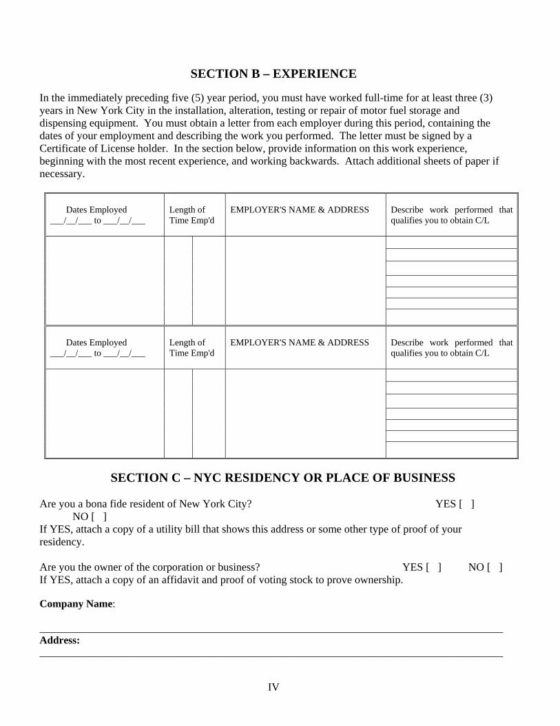
SECTION B – EXPERIENCE
In the immediately preceding five (5) year period, you must have worked full-time for at least three (3) years in New York City in the installation, alteration, testing or repair of motor fuel storage and dispensing equipment. You must obtain a letter from each employer during this period, containing the dates of your employment and describing the work you performed. The letter must be signed by a Certificate of License holder. In the section below, provide information on this work experience, beginning with the most recent experience, and working backwards. Attach additional sheets of paper if necessary.
Dates Employed ___/__/___ to ___/__/___
Length of Time Emp'd
EMPLOYER'S NAME & ADDRESS
Describe work performed that qualifies you to obtain C/L
Dates Employed ___/__/___ to ___/__/___
Length of Time Emp'd
EMPLOYER'S NAME & ADDRESS
Describe work performed that qualifies you to obtain C/L
SECTION C – NYC RESIDENCY OR PLACE OF BUSINESS Are you a bona fide resident of New York City? YES [ ] NO [ ] If YES, attach a copy of a utility bill that shows this address or some other type of proof of your residency. Are you the owner of the corporation or business? YES [ ] NO [ ] If YES, attach a copy of an affidavit and proof of voting stock to prove ownership. Company Name: ________________________________________________________________________________________ Address: ________________________________________________________________________________________

V
If your business is located outside of NYC, you must list an Agent for Receipt of Process located in NYC for Judicial OR Administrative Proceedings or Action. (P.O. Box not acceptable, please list a physical mailing address within the five boroughs of New York City that is authorized to receive legal papers if required) Full Name Address City Zip Code
SECTION D – INSURANCE
Attach a copy of the liability insurance policy that is required by Fire Rule §115-01 (g). The minimum of a $500,000 insurance policy with the FDNY being co-named on the policy is required. The policy must be issued by an approved insurance company that is licensed to do business in New York State and has an A.M. Best rating of A- or better. Such liability policy shall provide insurance coverage in the event of any death, injury, damage or other loss to persons or property arising from the conduct of the business or activity requiring the company certificate. Such coverage shall be at least as broad as that set forth in the edition of ISO Form CG 0001 most recently published as of the time coverage is obtained, and shall include completed operations. Termination or expiration of the policy will automatically terminate your company’s approval.
SECTION E - EDUCATION Attach a copy of your high school diploma or GED.
SECTION F – OATH OR AFFIRMANCE AND ACKNOWLEDGEMENT
I have hereunto affixed my signature and I certify that, subject to penalty pursuant to the New York State
Penal Law, New York City Administrative Code §15-220.1, Fire Department rule § 9-01, and any other
applicable law, rule or regulation, the information provided above is true and accurate.
I also affirm that I will notify the FDNY in writing within 24 hours of any changes regarding this form. ______________________________________ _________________________ SIGNATURE DATE

VI
STUDY MATERIAL AND TEST DESCRIPTION
About the Study Material This study material will help you prepare for the examination for the Certificate of License for motor fuel storage and dispensing system. This study material consists of 9 parts. The exam covers the entire booklet and any tables. It will not be provided to you during the test. It is critical that you read and understand this booklet to help increase your chance of passing this exam. The study material does not contain all of the information you need to know for motor fuel storage and dispensing system. It is your responsibility to become familiar with all applicable rules and regulations of the City of New York, even if they are not covered in this study material. You need to be familiar with the National Fire Protection Association (NFPA) 30, 30A and Fire Code Chapter 22, Chapter 34, and Fire Rule Chapter 22, Fire Rule Section §4834-01, and the New York City Building Code §26-229 and the regulations of the New York State Department of Environmental Conservation, as set forth in 6 NYCRR Parts 612, 613 and 614 which regulate the motor fuel storage and dispensing system in order to adequately prepare for the exam.
About the Test
All questions on the Certificate of License examination are of the multiple choice type with four alternative answers to each question. Only one answer is most correct for each question. If you do not answer a question, or if you mark more than one alternative your answer will be scored as incorrect. A score of 70% is required on the examination in order to qualify for the Certificate of License. Read each question carefully before marking your answer. There is no penalty for guessing.
Sample Questions
1. Who was the first President of the United States?
(A) George Jefferson. (B) George Washington (C) Bill Clinton. (D) Barack H. Obama.
The correct answer is "B". You would press "B" on your computer terminal. 2. The city in the United States referred to as The Big Apple is:
(A) Los Angeles. (B) Buffalo. (C) Florida. (D) New York.
The correct answer is "D". You would press "D" on your computer terminal.

1
FIRE STATISTICS AND FACTS According to the Fires at U.S. Service Stations report published by the Fire Analysis and Research Division of the National Fire Protection Association (NFPA) in April, 2011, an estimated 5,020 fires and explosions occurred at public service stations per year from 2004-2008. That means that, on average, one in every 13 service stations experienced a fire. These fires caused an annual average of two civilian deaths, 48 civilian injuries and $20 million in property damage. Fires in these occupancies represent a variety of incidents, including structure fires, vehicle fires, outdoor fires and other fires. The majority of incidents are vehicle fires (61%), but the majority of the property damage (59%), results from structure fires. In structure fires, heating equipment was the leading cause, followed by electrical distribution and lighting equipment. The top three leading items first ignited in structure fires at service stations are flammable or combustible liquids, gases, and associated piping or filter (22%); rubbish, trash, or waste (18%) and electrical cable or insulation (13%). The leading factors contributing to the ignition of different fires: Structure Fires:
(1) Electrical failures or malfunctions (2) Abandoned materials
Vehicle Fires: (1) Mechanical failures or malfunctions (2) Electrical failure or malfunction (3) A flammable liquid or gas being spilled
Outdoor and unclassified fires: (1) Abandoned or discarded materials or products (2) electrical failures or malfunctions

2
PART 1. DOCUMENTS, PERMIT, AND CERTIFICATE OF LICENSE 1.1 Design and Installation Documents (FC 105.3.9) Design and installation documents shall be submitted to the department for review and approval prior to the installation, alteration, repair or construction of automotive liquid motor fuel-dispensing facilities. As-built drawings are required to depict modified installations after the station is built or reconstructed The installation or alteration of a liquid motor fuel storage and dispensing system shall not be approved by the department unless the design and installation documents demonstrate that the proposed work complies with the regulations of the United States Environmental Protection Agency, as set forth in 40 CFR Part 280, and the regulations of the New York State Department of Environmental Conservation, as set forth in 6 NYCRR Parts 612, 613 and 614. The commissioner may require that the applicant for a permit or renewal thereof demonstrate, by submission of a certificate of occupancy or other authorization or approval issued by the Department of Buildings, that the building, structure or premises or portion thereof used for the manufacture, storage, handling or use of flammable or combustible liquids, are designed, constructed and occupied in accordance with the certificate of occupancy, the construction codes and the Electrical Code. No permit shall be issued when work requires the approval of the Commissioner of Buildings in connection with a material, operation or facility unless proof is submitted to the department that such work has been approved by the Commissioner of Buildings. 1.2 Permit A permit is required:
1. To store, handle or use amounts of gasoline and other petroleum-based Class I liquids other than paints, varnishes and lacquers, in excess of 2½ gallons, except that a permit is not required for the storage or use of gasoline or other petroleum-based Class I liquids in the fuel tank of a motor vehicle, aircraft, or watercraft.
2. To store, handle or use amounts of Class II or Class III liquids with a flash point of 300°F or less, other than paints, varnishes and lacquers, in excess of 10 gallons, except that a permit is not required for the storage or use of Class II or Class III liquids with a flash point of 300°F or less in the fuel tank of a motor vehicle, aircraft, or watercraft.
FDNY Site-specific permit authorizes the permit holder to store or handle motor fuels at a specific premises or location. A site-specific permit is valid for 12 months only. Every permit or renewal shall require an inspection and shall expire after twelve months. FDNY permits are not transferable, and any change in occupancy, operation, tenancy or ownership requires that a new permit be issued. The Certificate of License holder is responsible for making sure that all fire safety regulations and procedures are obeyed on the premises. Permits shall be readily available on the premise for inspection by Fire Department representatives.

3
1.3 Action and Time Periods on Application (FC105.2.4) Normally, the completed permit/documentation applications should be notified (either approved or denial) by the commissioner no latter than 40 calendar days from the submission. Except that on or before the fortieth day, the commissioner may, for good cause, extend such time for an additional 40 calendar days. When a permit application has been denied or preliminarily denied and is thereafter revised and resubmitted to meet the stated grounds for denial, the revised completed application shall be approved or denied or preliminarily denied in accordance with the foregoing procedures and time periods.
New regulations for stage II vapor recovery.
The New York State Department of Environmental Conservation (NYSDEC) has repealed the requirements for the stage II vapor collection systems. Existing installations with such systems which choose to decommission a stage II vapor collection system must have a W-16 Certificate of License holder to do the work and provide the FDNY with proper documentation when completed. The sample documentation is provided in the Appendix A. Contact Bulk Fuel Safety Unit (Tel: 718-999-2460) for additional information and forms. 1.4 Certificate of License and Certificate of Fitness (FC2201.7; FC2201.8) A certificate holder shall be responsible for:
1. The safe manufacturing, storage, handling, use, operation, maintenance, inspection, testing, repair and/or supervision of the material, operation or facility for which the certificate is required, in accordance with this code, the rules, and any other applicable laws, rules and regulations.
2. Notifying the department of any explosion, fire, reportable leak or other release of hazardous material, or other emergency related to the duties of his or her certificate.
3. Keeping such certificate upon his or her person or otherwise readily available for inspection by any representative of the department, at all times while conducting or supervising the material, operation or facility for which the certificate is required.
1.4.1 W-16 Certificate of License Persons who install, alter, test or repair any automotive or marine liquid motor fuel storage and dispensing systems shall hold a certificate of license or shall be employed by and perform such duties under the general supervision of a person holding such certificate. 1.4.2 P-15 Certificate of Fitness The dispensing of liquid motor fuel at motor fuel dispensing facilities shall be conducted by or under the supervision of a P15 C of F holder, who shall be responsible to ensure that dispensing operations are conducted and the facility is maintained in accordance with this chapter, as follows:
1. Dispensing operations shall be conducted by or under the personal supervision of a P15 C of F holder at self service automotive liquid motor fuel-dispensing facilities.
4
2. Dispensing operations shall be conducted by or under the personal supervision of a P15 C of F holder at fleet automotive liquid motor fuel-dispensing facilities.
3. Dispensing operations shall be conducted by or under the personal supervision of a P15 C of F holder at full service automotive liquid motor fuel-dispensing facilities.
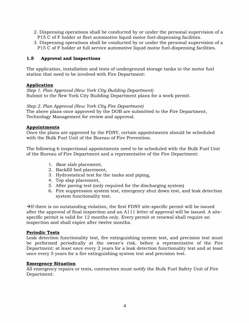
1.5 Approval and Inspections The application, installation and tests of underground storage tanks in the motor fuel station that need to be involved with Fire Department: Application Step 1. Plan Approval (New York City Building Department) Submit to the New York City Building Department plans for a work permit. Step 2. Plan Approval (New York City Fire Department) The above plans once approved by the DOB are submitted to the Fire Department, Technology Management for review and approval. Appointments Once the plans are approved by the FDNY, certain appointments should be scheduled with the Bulk Fuel Unit of the Bureau of Fire Prevention. The following 6 inspectional appointments need to be scheduled with the Bulk Fuel Unit of the Bureau of Fire Department and a representative of the Fire Department:
1. Base slab placement, 2. Backfill bed placement, 3. Hydrostatical test for the tanks and piping, 4. Top slap placement, 5. After paving test (only required for the discharging system) 6. Fire suppression system test, emergency shut down test, and leak detection
system functionality test. If there is no outstanding violation, the first FDNY site-specific permit will be issued after the approval of final inspection and an A111 letter of approval will be issued. A site-specific permit is valid for 12 months only. Every permit or renewal shall require an inspection and shall expire after twelve months. Periodic Tests Leak detection functionality test, fire extinguishing system test, and precision test must be performed periodically at the owner's risk, before a representative of the Fire Department: at least once every 2 years for a leak detection functionality test and at least once every 5 years for a fire extinguishing system test and precision test. Emergency Situation All emergency repairs or tests, contractors must notify the Bulk Fuel Safety Unit of Fire Department.

5
1.6 Related Regulations The installation, maintenance, and removal of motor fuel storage and dispensing system are required to comply with the following regulations:
Motor Fuel-Dispensing Facilities and Repair Garages [FC Chapter 22 and Fire Rule Chapter 22]
Flammable and Combustible Liquids [FC Chapter 34] Installation of Storage Tanks and Piping for Liquids Having Flashpoints of 100
Degrees Fahrenheit or Higher [Fire Rule Section 4834-01(l)(2)] Flammable and Combustible Liquids Code [NFPA 30, 2003 edition] Code for Motor Fuel Dispensing Facilities and Repair Garages [NFPA 30A, 2003
edition] Petroleum Bulk Storage Regulations [6 NYCRR Parts 612, 613 and 614] Safety Requirements During Excavation Operations [NYC DOB §26-229] Safety and Health Regulations for Construction [OSHA 29 CFR 1926.650 to 29
CFR 1926.652]

6
PART 2. DEFINITIONS
AUTOMOTIVE LIQUID MOTOR FUEL-DISPENSING FACILITY. Any building, structure or premises upon which or wherein, liquid motor fuel is stored and dispensed from a liquid motor fuel storage and dispensing system into the fuel tanks of motor vehicles or motorcycles.
BULK PLANT OR TERMINAL. Any premises upon which flammable or combustible liquids are received from marine vessel, pipeline, tank car or cargo tank and are stored or blended in bulk for the purpose of distributing such liquids by marine vessel, pipeline, tank car, cargo tank or container.
BULK TRANSFER. The loading or unloading of flammable or combustible liquids from or between marine vessels, pipelines, tank cars, cargo tanks or storage tanks.
P15 C OF F HOLDER. A person holding a certificate of fitness for the supervision of an automotive liquid motor fuel-dispensing facility, marine liquid motor fuel-dispensing facility or automotive CNG motor fuel-dispensing facility.
COMBUSTIBLE LIQUID. For purposes of transportation, a combustible liquid, as defined in the regulations of the United States Department of Transportation, as set forth in 49 CFR Section 173.120. For all other purposes, a liquid, other than a compressed gas or cryogenic fluid, having a closed cup flash point at or above 100°F (38°C), classified as follows: (e.g. diesel)
Class II. Liquids having a closed cup flash point at or above 100°F (38°C) and below 140°F (60°C).
Class IIIA. Liquids having a closed cup flash point at or above 140°F (60°C) and below 200°F (93°C).
Class IIIB. Liquids having closed cup flash points at or above 200°F (93°C).
DISPENSING DEVICE, OVERHEAD TYPE. A dispensing device mounted above a dispensing area, typically within a canopy structure, and characterized by the use of an overhead hose reel.
FLAMMABLE AND COMBUSTIBLE LIQUID STORAGE SYSTEM. A flammable or combustible liquid storage tank and all devices, equipment and systems associated with such tank, including the tank, piping, valves, fill connection, vent lines, pumps and any other ancillary equipment, except liquid motor fuel storage and dispensing systems and flammable and combustible liquid storage systems at a bulk plant or terminal used for bulk transfer operations.
FLAMMABLE LIQUID. For purposes of transportation, a flammable liquid defined in the regulations of the United States Department of Transportation, as set forth in 49 CFR Section 173.120. For all other purposes, a liquid, other than a compressed gas or cryogenic fluid, having a closed cup flash point below 100°F (38°C), classified as follows:
Class IA. Liquids having a flash point below 73°F (23°C) and having a boiling point below 100°F (38°C). Examples: Ethyl, Ether, Propylene.
Class IB. Liquids having a flash point below 73°F (23°C) and having a boiling point at or above 100°F (38°C). Examples: Acetone, Benzene, Gasoline, Methanol, Toluene, Jet fuel.

7
Class IC. Liquids having a flash point at or above 73°F (23°C) and below 100°F (38°C). Examples: Propyl, Alcohol, Turpentine.
FLAMMABLE LIQUID MOTOR FUEL. Gasoline or other flammable liquids used as fuel in the operation of motor vehicles, motorcycles, watercraft and aircraft.
FLASH POINT. The minimum temperature in degrees Fahrenheit at which a liquid will give off sufficient vapors to form an ignitable mixture with air near the surface or in the container, but will not sustain combustion. The flash point of a liquid shall be determined by appropriate test procedure and apparatus as specified in ASTM D 56, ASTM D 93 or ASTM D 3278.
FLEET AUTOMOTIVE LIQUID MOTOR FUEL-DISPENSING FACILITY. An automotive liquid motor fuel-dispensing facility wherein liquid motor fuel is stored and/or dispensed into the fuel tank of motor vehicles or motorcycles owned or operated by or on behalf of the owner of the facility, and where dispensing operations are conducted by persons employed by or otherwise working for the owner of the facility.
FULL SERVICE AUTOMOTIVE LIQUID MOTOR FUEL-DISPENSING FACILITY. An automotive liquid motor fuel-dispensing facility wherein liquid motor fuel is dispensed into the fuel tank of motor vehicles or motorcycles by a P15 C of F holder or, when under the personal supervision of a P15 C of F holder, by persons employed by or otherwise working for the owner of the facility.
GENERAL SUPERVISION. Supervision by the holder of any department certificate who is responsible for performing the duties of the certificate holder but need not be personally present on the premises at all times.
LIQUID MOTOR FUEL. Gasoline, diesel fuel or other flammable or combustible liquids used as fuel in the operation of motor vehicles, motorcycles, watercraft and aircraft.
LIQUID MOTOR FUEL STORAGE AND DISPENSING SYSTEM. A liquid motor fuel storage tank and all motor fuel storage and dispensing equipment associated with such tank, including the tank, piping, valves, fill connection catchment basins, vent lines, pumps, dispensing devices and any other ancillary equipment.
MOTOR VEHICLE. A vehicle or other conveyance having more than 2 running wheels and using liquid motor fuel or flammable gas as fuel for generating motive power, except such vehicles as have a storage tank with a maximum capacity for less than 2 gallons (7.6 L) of liquid motor fuel or flammable gas that generates energy that is equivalent to the energy generated by 2 gallons (7.6 L) of gasoline.
PERSONAL SUPERVISION. Supervision by the holder of any department certificate who is required to be personally present on the premises, or other proximate location acceptable to the department, while performing the duties for which the certificate is required.
PROCESS TRANSFER. The transfer of flammable or combustible liquids between cargo tanks or tank cars and containers, tanks piping and other equipment that is to be used in process operations.
PROCESSING VESSEL. A tank or other container used in manufacturing or other process operation that involves the use of a flammable or combustible liquid supplied from other than a cargo tank, tank car or pipeline.

8
SELF-SERVICE AUTOMOTIVE LIQUID MOTOR FUEL-DISPENSING FACILITY. An automotive liquid motor fuel-dispensing facility where liquid motor fuel is dispensed from a liquid motor fuel storage and dispensing system into the fuel tank of motor vehicles or motorcycles by customers of the facility.
STAGE I VAPOR RECOVERY. Stage I Vapor Recovery refers to the control of vapors during the transfer of gasoline from the cargo tank to the gasoline dispensing facility. Stage I Vapor Recovery systems control emissions during delivery and storage of gasoline at the gasoline dispensing facility. During gasoline delivery, emissions are controlled by diverting the displaced gasoline vapor from the storage tank into the tanker compartment of the vehicle unloading gasoline. The captured vapor is then transported back to the terminal for processing by condensation, adsorption or incineration.
STAGE II VAPOR RECOVERY. The New York State Department of Environmental Conservation (NYSDEC) has repealed the requirements for the stage II vapor collection systems. Existing installations with such systems which choose to decommission a stage II vapor collection system must have a W-16 Certificate of License holder to do the work and provide the FDNY with proper documentation when completed. The sample documentation is provided in the Appendix A. Contact Bulk Fuel Safety Unit for additional information and forms.
SUBSTANTIALLY MODIFIED FACILITY. Any existing facility which has been modified in one or more of the following ways:
(a) one or more new stationary tanks has been added;
(b) an existing stationary tank has been replaced, reconditioned or permanently closed; or
(c) a leaking storage tank has been replaced, repaired or permanently closed.
TANK, PROTECTED ABOVEGROUND. An atmospheric aboveground tank listed in accordance with UL 2085 or equivalent standard that is provided with integral secondary containment, protection from physical damage, and an insulation system intended to reduce the heat transferred to the primary tank when the tank is exposed to a high intensity liquid pool fire.

9
PART 3. GENERAL REQUIREMENTS 3.1 Piping, Valves, Fittings and Ancillary Equipment 3.1.1 Materials and testing (FC2206.6.2.7; FC2206.6.2.8; FC2206.6.3.1; FC2206.6.3.3; FC3403.6.2.1; FC3403.6.3; FC3403.6.12; Rule 2206-01(c)) ) Piping system components shall be designed and manufactured in accordance with NFPA 30, Chapter 3. Low-melting-point materials, such as aluminum, copper or brass, that soften on fire exposure, such as nonmetallic materials, and nonductile material, such as cast iron, shall be acceptable for use underground only in accordance with ANSI B31.9. Piping system components must be constructed of Schedule 40 steel or a higher Schedule steel. Approved nonmetallic piping, such as fiberglass-reinforced plastic or other equivalent corrosion-resistant material, may be installed underground. Underground tank piping must be installed underground, except for the vertical riser of the vent. Unless tested in accordance with the applicable section of ANSI B31.9, piping, before being covered, enclosed or placed in use, shall be hydrostatically tested to 150% of the maximum anticipated operating pressure of the system, but not less than 15 psig at the highest point of the system or precision tested. This test shall be maintained for a sufficient time period to complete visual inspection of joints and connections. For a minimum of 60 minutes, there shall be no leakage or permanent distortion. Piping system tests shall be conducted at the owner’s risk by his or her representative before a representative of the department. Care shall be exercised to ensure that these pressures are not applied to vented storage tanks. Such storage tanks shall be tested independently from the piping. Existing piping shall be tested in accordance with the requirements, upon a determination by the commissioner that such piping may be leaking. Piping that could contain flammable or combustible liquid vapors shall not be tested pneumatically, except that vapor-recovery piping may be tested pneumatically using an inert gas. Such tests shall be conducted at the owner’s risk by his or her representative. Upon completion of the installation of a motor fuel dispenser or motor fuel-dispensing pump, such dispenser and pump shall be tested for proper operation by a certificate of license holder. All readily accessible piping shall be inspected for any evidence of leaks. An affidavit executed by such installer attesting to compliance with this requirement shall be submitted to the Bulk Fuel Safety Unit of the Bureau of Fire Prevention. Piping, fittings, components and joint compounds shall be mutually compatible, and compatible with diesel fuel and other commonly-used combustible liquid motor fuels, including the additives commonly used in such combustible motor fuels. Joint compounds shall be listed and approved. 3.1.2 Protections (FC2206.6.1; FC3403.6.4) Posts or other approved means shall be provided to protect piping, valves, fittings or ancillary equipment subject to vehicular damage. Where subject to external corrosion, piping, related fluid-handling components and supports for both underground and
10
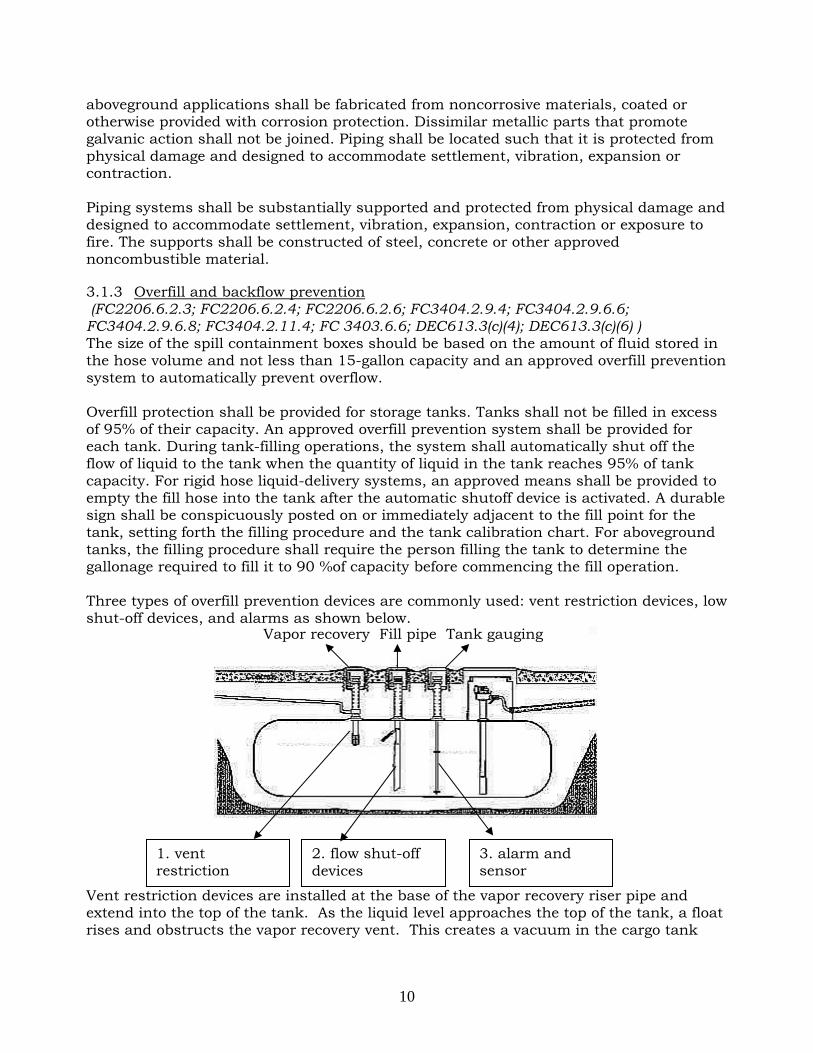
aboveground applications shall be fabricated from noncorrosive materials, coated or otherwise provided with corrosion protection. Dissimilar metallic parts that promote galvanic action shall not be joined. Piping shall be located such that it is protected from physical damage and designed to accommodate settlement, vibration, expansion or contraction. Piping systems shall be substantially supported and protected from physical damage and designed to accommodate settlement, vibration, expansion, contraction or exposure to fire. The supports shall be constructed of steel, concrete or other approved noncombustible material. 3.1.3 Overfill and backflow prevention (FC2206.6.2.3; FC2206.6.2.4; FC2206.6.2.6; FC3404.2.9.4; FC3404.2.9.6.6; FC3404.2.9.6.8; FC3404.2.11.4; FC 3403.6.6; DEC613.3(c)(4); DEC613.3(c)(6) ) The size of the spill containment boxes should be based on the amount of fluid stored in the hose volume and not less than 15-gallon capacity and an approved overfill prevention system to automatically prevent overflow. Overfill protection shall be provided for storage tanks. Tanks shall not be filled in excess of 95% of their capacity. An approved overfill prevention system shall be provided for each tank. During tank-filling operations, the system shall automatically shut off the flow of liquid to the tank when the quantity of liquid in the tank reaches 95% of tank capacity. For rigid hose liquid-delivery systems, an approved means shall be provided to empty the fill hose into the tank after the automatic shutoff device is activated. A durable sign shall be conspicuously posted on or immediately adjacent to the fill point for the tank, setting forth the filling procedure and the tank calibration chart. For aboveground tanks, the filling procedure shall require the person filling the tank to determine the gallonage required to fill it to 90 %of capacity before commencing the fill operation. Three types of overfill prevention devices are commonly used: vent restriction devices, low shut-off devices, and alarms as shown below.
Vent restriction devices are installed at the base of the vapor recovery riser pipe and extend into the top of the tank. As the liquid level approaches the top of the tank, a float rises and obstructs the vapor recovery vent. This creates a vacuum in the cargo tank
1. vent restriction
2. flow shut-off devices
3. alarm and sensor
Vapor recovery Fill pipe Tank gauging

11
compartment, dramatically slowing product flow. This alerts the driver to shut-off the flow from the tanker. This type of device is called a negative pressure overfill prevention.
The flow shut-off devices:
It will automatically shut off the flow of liquid to the tank when the liquid level reaches 95% of the tank capacity
The sensor and alarm:
(1) Valves and backflow protection Piping systems shall contain a sufficient number of manual control valves and check valves to operate the system properly and to protect the facility under both normal and
The sensor of the liquid level. It triggers the alarm.
Overfill alarm warms the truckman to stop transferring the motor fuel.
12
emergency conditions. Piping systems in connection with pumps shall contain a sufficient number of such valves to control properly the flow of liquids in normal operation and in the event of physical damage or fire exposure. Connections to pipelines or piping by which tank cars, cargo tanks, or marine vessels or other equipment discharge liquids into storage tanks shall be provided with check valves or block valves for automatic protection against backflow where the piping arrangement is such that backflow from the system is possible. All fill pipes leading to a pump-filled petroleum tank must be equipped with a properly functioning check valve or equivalent device which provides automatic protection against backflow. A check valve is required only when the piping arrangement of the fill pipe in such that backflow from the receiving tank is possible. Where loading and unloading is done through a common pipe system, a check valve is not required. However, a block valve shall be provided which is located so as to be readily accessible or remotely operable. Manual drainage-control valves shall be located at approved locations remote from the tanks, diked area, drainage system and impounding basin to ensure their operation in a fire condition. (2) Siphon prevention Approved antisiphon devices shall be installed in each external pipe connected to the protected aboveground tank when the pipe extends below the level of the top of the tank. 3.1.4 Connections, joints and bends (FC2206.6.2.2; FC3403.6.7; FC3403.6.9.1; FC3403.6.10; FC3404.2.7.5.1; FC3404.2.7.5.6 FC3404.2.9.6.7) Connections for tank openings below the liquid level shall be liquid tight. Joints shall be liquid tight and shall be welded, flanged or threaded except that listed flexible connectors are allowed. Threaded or flanged joints shall fit tightly by using approved methods and materials for the type of joint. Joints in piping systems used for Class I liquids (e.g. gasoline) shall be welded when located in concealed spaces within buildings or structures. Nonmetallic joints shall be subject to the approval of the commissioner and shall be installed in accordance with the manufacturer’s instructions. Pipe joints that are dependent on the friction characteristics or resiliency of combustible materials for liquid tightness of piping shall not be used in buildings or structures. Piping shall be secured to prevent disengagement at the fitting. (1) Connections for aboveground tanks. Aboveground tanks with connections located below normal liquid level shall be provided with internal or external isolation valves located as close as practical to the shell of the tank. Except for liquids whose chemical characteristics are incompatible with steel, such valves, when external, and their connections to the tank shall be of steel. The fill-pipe for aboveground tanks shall be provided with a means for making a direct connection to the cargo tank’s fuel-delivery hose so that liquid motor fuel is not exposed to the open air during the filling operation. Operator safety equipment for the filling operation shall be provided in accordance with OSHA regulations. Where any portion of the fill-pipe exterior to the tank extends below the level of the top of the tank, a check valve, a dry break coupling and a quick closing valve shall be installed at the fill

13
connection. The check valve must be installed in the fill pipe not more than 12 inches from the fill hose connection. Tank fill connections from a remote location are prohibited. (2) Joints for underground tanks. A flexible connectors on an underground storage tank’s suction, vent, and fill lines can protect the tank system from loads applied during settling. Flexible joints shall be listed and approved and shall be installed on underground liquid, vapor and vent piping at all of the following locations:
1. Where piping connects to underground tanks. 2. Where piping ends at pump islands and vent risers. 3. At points where differential movement in the piping can occur.
Fiberglass-reinforced plastic piping is not required to be provided with flexible joints in locations where both of the following conditions are present:
1. Piping does not exceed 4 inches in diameter. 2. Piping has a straight run of not less than 4 feet on one side of the connection
when such connections result in a change of direction. In lieu of the minimum 4-foot straight run length, approved and listed flexible joints are allowed to be used under dispensers and suction pumps, at submerged pumps and tanks, and where vents extend aboveground.
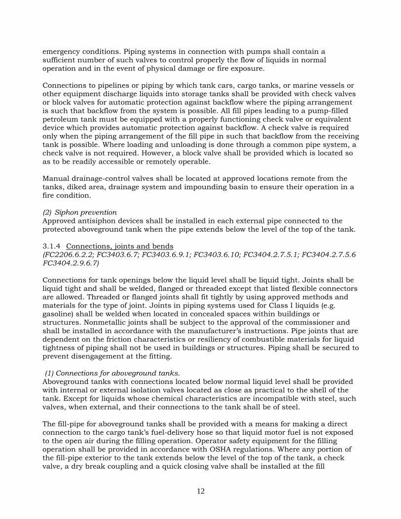
(3) Bends. The bending of pipe and tubing shall be performed in accordance with ANSI B31.9. 3.1.5 Tank vents and opening (FC2206.6.2.1; FC2206.6.2.9;FC2206.6.2.10; FC2206.6.2.11; FC3404.2.7.3; FC3404.2.7.3.2; FC3404.2.7.4; FC3404.2.7.5.4; FC3404.2.7.5.7; FC3404.2.9.6.2; FC3404.2.9.6.3) (1)Vent pipes Vent pipes shall be installed such that they will drain toward the tank without sags or traps in which liquid can collect. Each tank shall be provided with a separate unobstructed vent line, without any trap or device that causes excessive back pressure, and shall be maintained unobstructed at all times. Vent lines from tanks shall not be used for purposes other than venting unless approved. The lower end of the vent pipe shall not extend more than 1 inch through the top of the storage tank. Cross-connection between a vent pipe and fill pipe is prohibited. Where a battery of storage tanks designed to hold identical material is installed, vent pipes may be run into a main header. Vent shall be at least 1 1/4 inch in diameter for storage tanks not exceeding 1,100 gallon capacity and at least 2 inches in diameter for storage tanks of 1,100 gallons or more. Vent pipes shall be provided with an approved weatherproof hood having a free area of at least the pipe size area. Vent pipes shall terminate outside the building in a non-hazardous location, at least 2 feet from any building opening and not less than 2 feet nor more than 12 feet above the fill pipe terminal unless otherwise permitted by the Commissioner. If the vent pipe terminal is not visible from the fill pipe terminal location, a one inch tell-tale line shall be connected to the tank and shall parallel the fill pipe and terminate at
14
the fill terminal with an unthreaded end. Such telltale lines shall be provided with a check valve set to prevent flow of surface water to the storage tank.
Vent pipe outlets shall be located such that the vapors are released at a safe point outdoors and not less than 15 feet above the adjacent ground level. Vapors shall be discharged upward or horizontally away from adjacent walls to assist in vapor dispersion. Vent outlets shall be located such that flammable or combustible vapors will not be trapped by eaves or other obstructions and shall be at least 10 feet from building openings or lot lines. Tank openings for aboveground tanks shall be through the top only. There shall be no openings except those necessary to inspect, fill, empty and vent the tank.
Tank vent piping shall not be manifolded unless required for special purposes such as vapor recovery, vapor conservation or air pollution control.
(a)Aboveground tanks. For aboveground tanks, manifolded vent pipes shall be adequately sized to prevent system pressure limits from being exceeded when manifolded tanks are subject to the same fire exposure. (b) Underground tanks. For underground tanks, manifolded vent pipes shall be sized to prevent system pressure limits from being exceeded when manifolded tanks are filled simultaneously.
(2) Tank openings for vapor recovery Tank openings provided for purposes of vapor recovery shall be protected against vapor release by means of a spring-loaded check valve or dry-break connections, or other approved device, unless the opening is a pipe connected to a vapor processing system. Openings designed for combined fill and vapor recovery shall also be protected against
Posts that protect piping, valves, fittings or ancillary equipment subject to vehicular damage.

15
vapor release unless connection of the liquid delivery line to the fill pipe simultaneously connects the vapor recovery line. Connections shall be vapor tight. Filling, emptying and vapor recovery connections to tanks shall be located outdoors at a location free from sources of ignition and not less than 10 feet away from building openings or lot lines. Such openings shall be provided with a liquid-tight cap which shall be closed when not in use and properly identified.
(3) Special devices (a) Pressure relief devices. Where liquid motor fuel may become trapped between shutoff valves and/or check valves, affected piping sections shall be provided with pressure-relief devices that will discharge the pressure generated by thermal expansion back into the tank. (b) Manual gauging. Openings for manual gauging, if independent of the fill pipe, shall be provided with a liquid-tight cap or cover. Covers shall be kept closed when not gauging. Openings for manual gauging shall not be permitted for tanks installed indoors. 3.1.6 Filling pipes (Rule 4834(d)(1)f) The filling pipe shall be at least 2 inches and not larger than 4 inches nominal inside diameter, and shall be laid at a descending grade to the tank, terminating within 6 inches of the bottom of the tank. The intake of a filling pipe shall be located outside of any building and not less than 10 feet from any door, subway grating or basement opening, and in a heavy metal box, which shall be sunk flush with the sidewalk at the curb level, or at some other location offering equal facilities for the filling of the tank and fitted with a heavy metal cover, which shall be liquid tight and kept closed when not in use. The filling pipe shall be closed at the intake by a cock or valve fitted with a coupling for attaching to the tank truck, and with a liquid tight cap or plug to close the opening when not in use. The filling pipe shall be provided with a screen made of one thickness of 20-mesh brass wire gauze, placed immediately below the filling cock or valve. Where a storage system for flammable liquids and a storage system for diesel motor fuel oil and/or fuel oil are to be used on the same premises, the terminal of the diesel motor fuel oil and/or fuel oil fill pipe shall be provided with a left handed thread and the fill pipe fitting shall be of a different size than that required for the fill pipe to tanks containing flammable liquids. 3.2 Labeling and Signage 3.2.1 Color coding and symbols of fill ports (DEC613.3(b)(2), DEC613.3(b)(3)) The owner or operator must permanently mark all fill ports to identify the product inside the tank. These markings must be consistent with the color and symbol code of the American Petroleum Institute which follows. The colors to be used are:

16
(i) High gasoline Red (ii) Middle gasoline Blue (iii) Lower gasoline White (iv) High unleaded gasoline Red w/white cross (v) Middle unleaded gasoline Blue w/white cross (vi) Lower unleaded gasoline White w/black cross (vii) Vapor recovery Orange (viii) Diesel Yellow (ix) #1 fuel oil Purple w/yellow bar (x) #2 fuel oil Green (xi) Kerosene Brown
The symbols to be used are:
(i) a circle for gasoline products and vapor recovery lines;
(ii) hexagon for other distillates; and (iii) a border must be painted around
fuel products containing extenders such as alcohol. The border will be black around a white symbol and white around all other colors.
3.2.2 Warning signs (FC2204.2.3; FC2204.2.6) (1) Control area sign. A durable metal sign that reads as follows shall be posted in plain view within the control area:
Emergency Procedures: Shut off product pumps.
Direct vehicle occupants to exit vehicles and leave area immediately.
Keep all persons away from the area. Manually activate fire extinguishing system.
Notify the Fire Department (Call 911).

17
(2) Dispensing area signs and instructions. Durable warning signs shall be conspicuously posted on or immediately adjacent to each dispenser in the fuel-dispensing area and shall state the following:
1. It is illegal and dangerous to fill unapproved containers with fuel. 2. Smoking is prohibited. 3. The engine shall be shut off during the refueling process. 4. Portable containers shall not be filled while located inside the trunk, passenger
compartment, or truck bed of a vehicle. 5. It is unlawful for customers to fill portable containers. See attendant for
assistance. Dispenser operating instructions shall be conspicuously posted in approved locations on every dispenser and shall indicate the location of the emergency controls.
The view of the sign should not be obstructed.

18
PART 4. UNDERGROUND LIQUID MOTOR FUEL STORAGE TANK 4.1 Tank Contents and Capacity Limitations (FC2206.2.1.3#4; FC2206.2.3.2; FC3404.1.2.2) Individual underground storage tanks shall not exceed a capacity of 12,000 gallons. The aggregate capacity at a facility in both aboveground and underground tanks shall not exceed 40,000 gallons. Underground tanks shall not store petroleum products containing mixtures of a nonpetroleum nature, such as ethanol or methanol blends, without evidence of compatibility such as a manufacturer’s letter stating the compatibility. 4.2 Design and Constructions of the Tanks 4.2.1 General requirements (FC2206.2.1.3) The manufacture of the tanks and all related equipments must be UL certificated and tanks must be designed and constructed in accordance with the following:
1. Tanks shall be completely double-walled and constructed of steel, fiberglass-reinforced plastic or a combination of both materials. The secondary tank shall be capable of containing any leakage from the primary tank.
2. Tanks shall be designed and constructed to withstand 1.5 times the maximum operating loads and stresses, regardless of the amount of liquid motor fuel contained in the tank. Such capabilities shall be established by buoyancy calculations and load and stress analyses.
3. Tanks shall be designed and constructed to withstand a pressure of 15 psig or 1½ times the maximum anticipated static head pressure, whichever is greater, for the primary tank and 5 psig for the secondary tank.
4.2.2 Cathodically protected steel tanks (DEC614.3(e) Rule 2206-01(c)) Cathodically protected steel tanks used for underground storage of petroleum must meet or exceed the design regulated by the New York State Department of Environmental Conservation 614.3(e) and manufacturing standards. Such steel tanks must be cathodically protected with sacrificial anodes or an impressed current cathodic protection system designed in accordance with the applicable National Association of Corrosion Engineers (NACE) standard or other approved standard(e.g. API RP 1632; ULC-S603.1M; STI-P3; NACE RP-0169; NACE RP-0285; UL 1746 or STI RP 892). The cathodic protection system must be designed to provide a minimum of 30 years of protection. Cathodic protection systems shall be designed by a trained person knowledgeable of the requirements of the United States Environmental Protection Agency for such systems. Such person shall first inspect the site and test the site for soil resistivity and the presence of stray currents. A qualified engineer or corrosion specialist must personally supervise the installation of the cathodic protection system where this is necessary to assure that the system has been installed as designed. Each cathodic protection system must have a monitor which enables the owner or operator to check on the adequacy of cathodic protection. Tanks which are protected by sacrificial anodes must be electrically insulated from the piping system with di-electric fittings, bushings, washers, sleeves or gaskets which are chemically stable when exposed to petroleum, petroleum additives, or corrosive soils.

19
Cathodic protection systems shall be inspected and tested in the presence of a representative of the Fire Department at the time of installation in compliance with the applicable National Association of Corrosion Engineers standard and the following procedures:
(A) All piping shall be subjected to a holiday test and tanks and associated piping shall be subjected to an electrical continuity test. Any holiday located during a spark test shall be repaired as per coating specifications before the tank or piping excavation is backfilled.
(B) Upon completion of the underground motor fuel storage tank installation, the following information and documentation shall be submitted to the Fire Department:
(1) An "as-built" drawing showing number, size (weight) and location of all anodes and test stations.
(2) An affidavit in a form satisfactory to the Fire Department, executed by the person who designed and supervised the installation of the cathodic protection system, setting forth the type of cathodic protection system installed, a description of the system and its location, the date of final inspection of the installed system, and such person's certification that the system has been installed and is functioning properly and that the system is designed to provide corrosion protection for at least 30 years.
If steel piping is installed underground, it is also required to have Cathodic protection.
Cathodic protection system

20
4.2.3 Coatings (DEC614.3(e);Rule 2206-01(d)) Tanks must be factory-coated with coal tar-based epoxy or other coating which will provide equivalent protection and corrosion resistance. The coating must have a minimum finished thickness of 0.01 inch on the shell and 0.015 inch on the head. The coating must be electrically tested for short circuits or coating faults. Defects and any inadequacies in the coating must be repaired. The application of the coating must be in strict accordance with the instructions of the supplier of the coating material. Coatings steel underground storage tanks and piping at motor fuel dispensing facilities shall be designed and installed in compliance with the following requirements:
(1) Types of coatings. Steel tanks shall be factory-coated with a dielectric material acceptable to the Fire Department. The coating's coefficient of thermal expansion must be compatible with steel so that stresses due to temperature changes do not affect the soundness of the coating and the permanent bond which exists between the coating and the steel. The coating must be of sufficient density and strength so that it will not crack, wear, soften or disbond under normal service conditions. The coating must be stable under adverse underground electrolytic conditions and shall be chemically resistant to the products stored. The coating shall have been factory inspected for air pockets, cracks, blisters and electrically tested with a holiday detector at a minimum of 10,000 volts for coating defects such as pinholes. (2) Site inspection. All coated tanks shall be inspected on site for coating defects prior to installation. An affidavit attesting to the integrity of the tank coating shall be submitted by a certificate of license holder upon the request of the Fire Department.
4.3 Location (FC3404.2.11.2; FC3404.2.11.3) The underground shall be in compliance with the following requirements:
1. Tanks shall be installed so that the external forces exerted from building foundations and support loads are not transmitted to the tanks. The distance from any part of a tank to the nearest wall of any basement, pit, cellar or any property line shall not be less than 3 feet. Tanks shall not be placed less than 20 feet from a subway wall.
2. Tanks shall be installed so that the highest point of the tank is not less than 2 feet below the level of the lowest cellar floor of any building within a radius of 10 feet from the tank. No tank shall be located under a sidewalk or beyond the property line.
3. A minimum distance of 1 foot, shell to shell, shall be maintained between underground tanks.
4. Manufacturer's installation instructions.

21
Excavation for underground storage tanks shall be made with due care to avoid undermining of foundations of existing structures. Underground tanks shall be set on firm foundations and surrounded with at least 6 inches of noncorrosive inert material, in accordance with the manufacturer's installation instructions. 4.4 Leak Detection (FC2205.2.3; FC2206.7.7; FC3404.2.7.10; FC3404.2.11.5) Underground liquid motor fuel storage and dispensing systems shall be provided with a leak detection system in accordance with the following:
1. Leak detection systems shall be listed and approved. 2. Leak detection systems shall be tested at the time of installation at the owner’s risk
by his or her representative before a representative of the department.
At least 1 foot
It is recommended to have at least minimum distance of 18” between the tank and the excavation wall.

22
3. The leak detection system shall provide continuous monitoring of the tank's interstitial space.
(Leak/Overfill detection panel)
4. The leak detection system shall provide continuous monitoring of liquid motor fuel pump sumps. Activation of the leak detection system shall cause shutdown of the liquid motor fuel pumps.
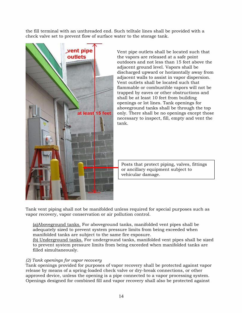
5. The leak detection system shall provide continuous monitoring of dispenser pans
whenever such pans are provided. Activation of the leak detection system shall cause shutdown of the affected dispenser or liquid motor fuel pump supplying such dispenser.
Sensor of the leak detection system for monitoring the fuel pump sumps.
Floating sensor activate s the leak detection system shutdown the fuel pumps.
23
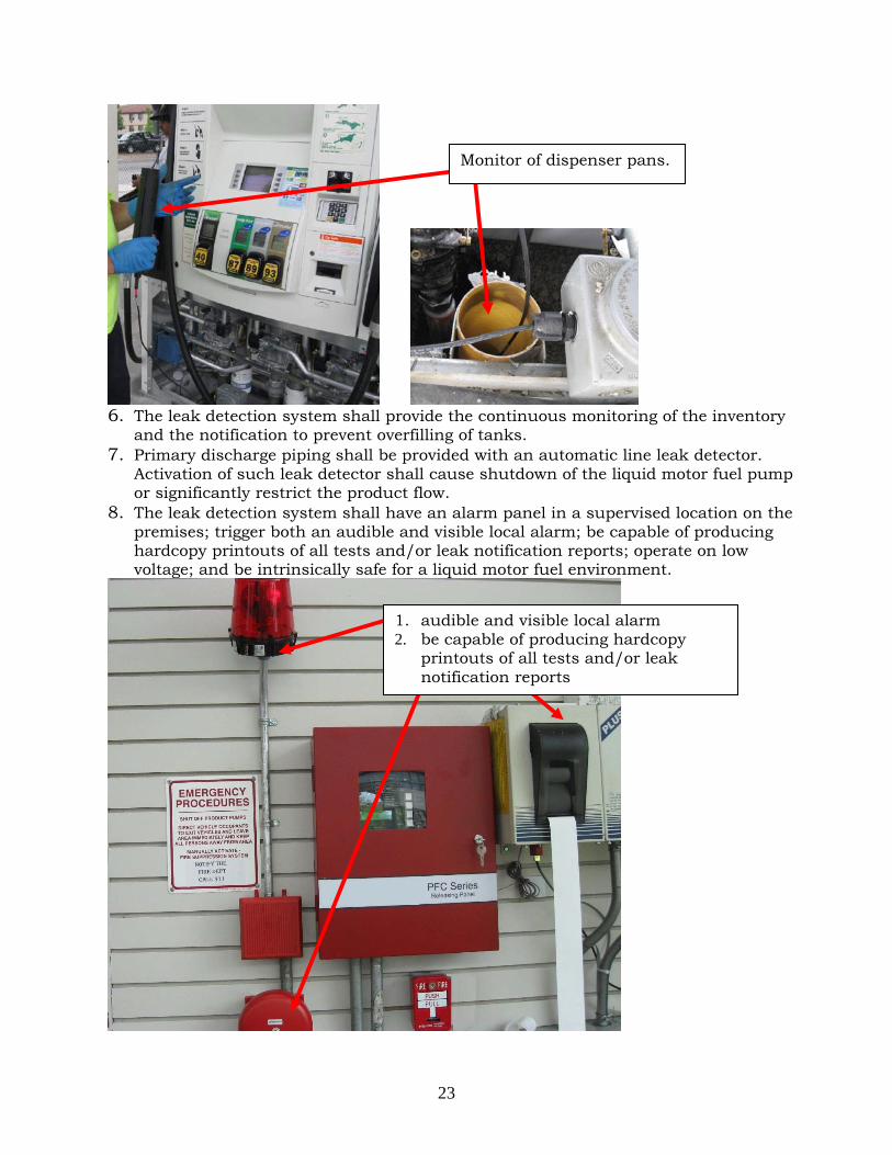
6. The leak detection system shall provide the continuous monitoring of the inventory
and the notification to prevent overfilling of tanks. 7. Primary discharge piping shall be provided with an automatic line leak detector.
Activation of such leak detector shall cause shutdown of the liquid motor fuel pump or significantly restrict the product flow.
8. The leak detection system shall have an alarm panel in a supervised location on the premises; trigger both an audible and visible local alarm; be capable of producing hardcopy printouts of all tests and/or leak notification reports; operate on low voltage; and be intrinsically safe for a liquid motor fuel environment.
Monitor of dispenser pans.
1. audible and visible local alarm 2. be capable of producing hardcopy
printouts of all tests and/or leak notification reports

24
Underground storage tank systems shall be provided with an approved method of leak detection from any component of the system that is designed and installed in accordance with NFPA 30. Leak detection systems shall be tested at the time of installation at the owner’s risk by his or her representative before a representative of the department. The leak detection system shall be inspected daily for proper operation and tested at least once every 2 years by a person holding a certificate of license. Such test shall confirm that all leak detection equipment and associated alarms are in good working order. Daily inventory records shall be maintained for underground storage tank systems. A consistent or accidental loss of liquid, or other indication of a leak from a tank system, shall be reported immediately to the department and other authorities having jurisdiction. Leaking tanks shall be promptly emptied, repaired and returned to service, sealed in place or removed. 4.5 Installation of Underground Tank and Piping Systems 4.5.1 Safety requirements during excavation operations (NYC DOB 26-229; FC2206.9.7; FC2206.10; OSHA part 1926.650 to 1926.652) Excavating is recognized as one of the most hazardous construction operations. OSHA part 1926.650 to 1926.652 and the following requirements regulated by New York City Building Department (NYC DOB)shall apply to the conduct of all excavation operations, whether for construction purposes or otherwise: (1) Protection of persons and adjoining property. Any person causing an excavation to be made shall provide adequate fencing on all open sides of the excavation, with suitable means of exit therefrom, and shall also provide such sheet piling, bracing and other supports as may be necessary to prevent the sides of the excavation from caving in before permanent supports are provided. Such person shall be afforded a license to enter and inspect adjoining property, and to perform such work thereon as may be necessary for such purpose; otherwise, the duty of providing safe support for any adjoining property, shall devolve upon the owner thereof, who shall be afforded a similar license with respect to the property where the excavation is to be made. (2) Protection of adjoining buildings. Whenever the safety of any adjoining building is or may be affected by an excavation, it shall be the duty of the person causing such excavation to be made to provide safe support for such building regardless of the depth of its foundations, provided such person is afforded a license to enter and inspect the adjoining building and property, and to perform such work thereon as may be necessary for such purpose; otherwise, such duty shall devolve upon the owner of the adjoining building, who shall be afforded a similar license with respect to the property where the excavation is to be made.
(a) Such person shall support the vertical load of the adjoining structure by proper foundations, underpinning, or other equivalent means where the level of the foundations of the adjoining structure is at or above the level of the bottom of the new excavation.
(b) Where the existing adjoining structure is below the level of the new construction, provision shall be made to support any increased vertical or lateral load on the existing adjoining structure caused by the new construction.

25
(c) Where the new construction will result in a decrease in the frost protection for an existing foundation below the minimums requirements, the existing foundation shall be modified as necessary to restore the required frost protection.
(3) Support of party walls. Whenever an adjoining party wall is intended to be used by the person causing an excavation to be made, and such party wall is in good condition and sufficient for the uses of the existing and proposed buildings, it shall be the duty of such person to protect such party wall and support it by proper foundations, so that it shall be and remain practically as safe as it was before the excavation was commenced. (4) Owner responsibility. The responsibility of affording any license referred to this section, shall rest upon the owner of the property involved; and in case any tenant of such owner fails or refuses to permit the owner to afford such license, such failure or refusal shall be a cause to the owner for dispossessing such tenant through appropriate legal proceedings for recovering possession of real property. 4.5.2 Pouring concrete and backfilling The pouring of concrete for the base and top slab, the backfilling of tank and piping, and the construction of the top slab support shall be witnessed by a representative of the department at time of installation. The backfill material surrounding an underground storage tank is a critical part of a proper tank installation. The backfill materials must be manufacture approved. The object of backfill is to construct a uniform, homogenous envelope of firm, aggregate material around the tank. The material is to be washed, free-flowing, and free of ice, snow and debris. Good backfill material is hardness or stability when exposed to water or loads. The backfill material must not contain any foreign material, such as rocks, brick, clay, wood, native soil, etc. Materials like soft limestone, sandstone or shale should not be used as backfill because they break down over time. Sharp objects must not contact
Care must be taken to avoid undermining the foundations of existing structure. In order to prevent the downward force from the existing structure will not transmit to the tanks, installer should : (1) determine the depth of burial
need for the tank; and (2) determine the line that would
fall into the ground from a 45° angle downward from the corner(s) of footing of the foundation that is closet to the tank. Make sure that the tanks do not fall within the shadow of the 45° angle line drawn from the foundation’s footing.

26
the tank at any time. Common backfill material includes Pea Gravel and Stone or Gravel Crushings. Pea Gravel should be a natural, rounded aggregate, clean and free flowing, with particle size not less than 1/8 inch or more than ¾ inch diameter. Stone or gravel crushings should be clean and free flowing with angular particle size not less than 1/8 inch or more than ½ inch diameter.
It is recommended to envelop the tanks with a permeable geotexile or filter fabric, allow the passage of water in and out of the excavation but prevents the migration and mixing of in situ soil and the backfill material. The fabric can help preserve the integrity of the backfill envelope that surrounds and supports the tank.
4.5.3 Preparation for installation Do not release the ratchet straps securing the tank to the truck or flat bed trailer, etc. until the lifting equipment is secured to the tank’s lifting lug(s). Do not use a sling around the tank’s belly to lift it. Failure to do so could result in death or serious injury. Underground tanks should be lifted with steel rope by the top lugs. Use a spreader bar for lifting a tank that has two or more lifting lugs. Use a lifting cable instead of a spreader bar if the angle between the cable and the tank top exceeds 60 degrees. The ground level to the top of the tank should not exceed 7 feet.
60° maximum internal angle

27
4.5.4 Installation of underground tank and piping systems (FC2206.10; NFPA30 22.5.2; manufacturer’s manual) The installation of tank and piping systems shall be in accordance with the following:
1. Tanks shall be located so that the forces from building foundations and support loads are not transmitted to the tanks. The distance from any part of a tank to the nearest wall of any basement, pit, cellar or any property line shall not be less than 3 feet. Tanks shall not be placed less than 20 feet from a subway wall.
2. Tanks shall be installed so that the highest point of the tank is not less than 2 feet below the level of the lowest cellar floor of any building within a radius of 10 feet from the tank. No tank shall be located under a sidewalk or beyond the property line of the automotive liquid motor fuel-dispensing facility.
3. Tanks shall be placed on a 12-inch thick base slab approved by the Department of Buildings, or installed in such other manner as may be approved by the Commissioner of Buildings, and secured against flotation. The system used for anchoring the tank shall not damage the tank or its coating.
The orange line indicate the 12” height.
The concrete used for the base slab is recommended to have a minimum compressive strength of 2500 psi at 28 days.

28
4. Tanks shall be placed on a bed of approved backfill material in accordance with
manufacturer's specifications. The backfill material shall evenly and completely support the bottom quadrant of the tank. The backfill material shall be carefully placed along the bottom, under the sides and under the end caps or heads of the tank, by shoveling and tamping. Backfilling shall then be completed in 12-inch lifts placed uniformly around the tank. Provision shall be made, consistent with site conditions, to prevent the migration of backfill.
5. Tanks shall be covered with at least 12
inches of compacted backfill on top with a reinforced concrete slab not less than 8 inches thick, which shall extend not less than 12 inches beyond the horizontal outlines of the tank. If the tanks are subjected to traffic, they should protected by at least 18 inches of compacted backfill and at least 8 inches thick top concrete slab. The recommended maximum burial depth is 7 feet. The slab and its support shall be of a design approved by the New York City Department of Buildings. The concrete used for the top slab is recommended to have a minimum compressive strength of 3500 psi at 28 days.
6. Fill, suction and discharge piping shall be encased in 4 inches of concrete or
covered by a minimum of 18 inches of manufacturer-approved backfill, or covered by 4 inches of manufacturer-approved backfill and an 8-inch reinforced concrete slab.
7. Not more than 40,000 gallons of liquid motor fuel shall be stored at any facility, including liquid motor fuel stored in aboveground tanks.
8. Tanks containing identical products may discharge liquid motor fuel into a common line, provided that the total aggregate capacity of any group of such tanks discharging into a common line does not exceed 12,000 gallons.
9. Tank connections shall be designed and located so as to: 9.1. Minimize the maneuvering necessary to position a cargo tank to make the
delivery.
1. Anchor the tank with ropes to prevent buoyancy and reduce top slab settlement.
2. Block a tank with rubber tires or sandbags to prevent rolling.

29
9.2. Minimize obstructing a public right of way or motorists’ view of roadways, or impeding the movement of motor vehicles or pedestrians, during deliveries.
9.3. Provide connections by means of approved liquid and vapor-tight connections. 10. Tanks installed underground inside a building or structure shall be provided with
an approved liquid level-indicating device. Liquid-level indicating devices shall be designed and constructed to prevent the escape of liquid or vapor and shall be approved.
11. Test wells shall be prohibited in tanks located underground inside a building or structure. Unused tank openings shall be permanently sealed at the tank to prevent removal of plugs or covers.
12. Secondary containment piping shall be required on all nonmetallic product-carrying pipes except direct fill lines, suction lines or siphon lines containing only one check valve located at the highest point of the line.
13. Underground piping shall have a slope of not less than 1/8 inch per foot pitched toward the tank and shall be installed so as to facilitate initial and periodic testing.
14. Flexible joints shall be installed. 15. Each underground motor fuel storage tank shall be provided with a separate
unobstructed vent line without any trap or device that causes excessive back pressure.
16. Vent piping shall be installed not less than 12 inches below the finished surface measured from the point where the piping rises vertically and shall slope toward the tank.
17. Vent outlets shall discharge outdoors and upward. The discharge point shall be no less than 15 feet above the adjacent ground level and no less than 10 feet from the nearest building opening.
18. An approved overfill prevention device shall be provided to prevent overfilling. When installed in diesel fuel tanks, such overfill prevention device shall be designed to withstand the pressure generated by the cargo tank discharge pump and shall automatically shut off the flow into the tank when the tank is not more than 95% full.
19. Each tank fill connection shall be provided with a catchment basin with a capacity of at least 15 gallons. The catchment basins must be approved by FDNY. The contents of the catchment basin shall be automatically drained into the tank without overfilling the tank after the transfer from the cargo tank is completed provided.
20. Where the discharging piping leak detector required by Fire Department does not cause shutdown of the liquid motor fuel pump, secondary containment piping shall be provided.
4.6 Monitoring, Inspection and Testing (DEC 613.5(b);DEC 614.5; FC2206.9; FC3404.2.11.7,Rule 2206-02) 4.6.1 Monitoring at new underground storage tanks (a) General requirement. All new tanks must have one of the following leak monitoring systems:
(1) a double-walled tank with monitoring of the interstitial (annular) space; (2) an in-tank monitoring system; or (3) an observation well or wells.

30
(b) Monitoring of double-walled tanks. If a double-walled tank is used, the interstitial space must be monitored for tightness using pressure monitoring, vacuum monitoring, electronic monitoring, manual sampling once per week or an equivalent method. In other words, tank interstitial space leak monitoring must monitor the space between the inner and outer tanks of a double wall tank system for leakage. (c) In-tank monitoring systems. If an in-tank monitoring system is used, it must consist of in-tank equipment which provides continuous monitoring of any leakage from the tank of 0.2 gallons per hour or larger. (d) Observation wells.
(1) If an observation (monitoring) well or series of wells are used, they must consist of slotted or screened wells at least four inches in diameter. The well must be installed down-gradient in the groundwater or at a sump within the secondary containment system and to an elevation at least 24 inches below the bottom of the tank. The well must be installed within the backfill surrounding the tank. At least one well is required at each facility. The well must be monitored for traces of petroleum at least once per week as required in section 613.5(b)(3) of this Title.
(2) An observation well may be used as a vapor or odor well if the site is uncontaminated. If the well becomes contaminated with petroleum, it must either be purged free of odors or monitored for petroleum contamination through another method capable of detecting 1/64 of an inch of petroleum floating on the water surface or other method acceptable to the Department.
(3) Wells must be protected from damage if located in a traffic area. (4) Wells must be sealed or capped so as to preclude liquid from entering the well
from the surface and clearly marked as monitoring wells to prevent accidental delivery of product.
4.6.2 Periodic Maintenance Requirements. Underground storage tanks at liquid motor fuel dispensing facilities shall be maintained in accordance with the following procedures:
The observation well. The well must be sealed or capped.

31
(1) Overfill prevention devices. The overfill prevention devices shall be inspected for proper operation at least once every 2 years by a person holding a W-16 certificate of license. (2) Cathodic protection systems. Tanks and piping systems provided with cathodic protection systems shall be inspected, tested and otherwise maintained to ensure continuous corrosion protection. Cathodic protection systems shall be inspected for proper operation by a trained person knowledgeable of the requirements of the United States Environmental Protection Agency for such systems. Cathodic protection systems other than impressed current cathodic protection systems shall be inspected within 6 months of installation and at least once a year thereafter. Impressed current cathodic protection systems shall be inspected at least once every 60 days by the authorized person (e.g NACE certificated person). (3) Leak detection systems. Leak detection systems is recommended be inspected for proper operation at least once per shift by a P-15 certificate of fitness holder responsible for the supervision of the motor fuel-dispensing facility. A log book should be kept within control area. 4.6.3 Initial tank test All new underground and aboveground tanks shall be only hydrostatically tested at 15 psig, or 1½ times the maximum anticipated static head pressure, whichever is greater, for the inner tank, and pneumatically or hydrostatically at 5 psig for the annular space (secondary containment tank) before installation. Based on manufacturer’s manual, the test air should be introduced via a valved manifold with pressure gauge. Do not overpressurize the tank. Position the pressure gauges so that the pressure readings can be clearly read at all times. The pressure gauge must have a pressure-relief valve and a vacuum gage must not be used in place of a pressure gauge. Failure to follow this warning could result in death or serious injury. When a pneumatic test is allowed, an inert gas shall be used. Test pressure shall be maintained for a sufficient time to complete visual inspection, but not less than 1 hour. A tank shall be deemed to have passed the test if it shows no evidence of leakage or permanent deformation. 4.6.4 Initial piping test After backfill of the tanks, primary piping shall be tested hydrostatically to 1½ times the maximum anticipated operating pressure, but not less than 15 psig. If there is any discharge lines, they must be tested at not less than 50 psig. Secondary containment piping (annular space) shall be tested pneumatically at 5 psig. After backfill and pouring of the top slab, discharge piping shall be tested hydrostatically at 1½ times the maximum anticipated pressure, but not less than 50 psig. Secondary containment piping (annular space) shall be tested pneumatically at 5 psig. When a pneumatic test is allowed, an inert gas shall be used. Hydrostatic test pressure shall be maintained for sufficient time to complete visual inspection but not less than 1 hour. The test shall show that there is no evidence of leakage. Test pressure for aboveground tank piping shall be at 1½ times the maximum anticipated operating pressure but not less than 100 psig.

32
4.6.5 Leak detection functionality test (Rule 2206-02) Leak detection systems monitoring underground liquid motor fuel storage systems shall be tested to confirm that all leak detection equipment and associated alarms are in good working order. The leak detection system functionality test shall be conducted by a W-16 Certificate of License holder for liquid motor fuel storage and dispensing systems, or a person employed and supervised by such Certificate of License holder. This test shall be scheduled with the Bulk Fuel Safety Unit of the Bureau of Fire Prevention. The individual conducting the test shall remain on the premises while such test is being conducted and until the system has been returned to normal operation in accordance with the FDNY requirements. The Fire Department may require individuals performing such leak detection test to be trained and/or certified by the manufacturer to conduct such test. Upon request, satisfactory proof shall be submitted to the Fire Department of the individual's training/certification for such leak detection system. The areas surrounding the dispensers, tanks or other equipment or systems tested shall be cordoned off by portable barricades or signs, rope or tape to prevent unauthorized persons or motor vehicles from entering the area. The test must not be conducted if the fire extinguishing system required to protect the dispensers is out-of-service or not in good working order. All sources of ignition in the test area shall be eliminated from the area in which a leak detection system functionality test is to be conducted. Signs reading "NO SMOKING - NO OPEN FLAMES" shall be conspicuously posted in such area. A portable fire extinguisher having at least a 40-B:C rating shall be readily available for use. All electrical equipment used for testing shall be of a type listed as intrinsically safe or suitable for use in hazardous locations. Interlocks shall be provided to ensure that grounding is made prior to electrical contact. Power to electrical equipment shall not be turned on until all electrical connections are made. Connection to power source shall be the final connection made. Testing Requirements: Leak detection system functionality tests shall be conducted in accordance with the manufacturer’s instructions and the following standards and procedures:
(1) Testing of probes. Leak detection probes shall be removed from their installed location, and manually tested by exposing such probes to liquid motor fuel. Probes capable of discriminating liquid motor fuel from water shall also be exposed to water. Leak detection probes which cannot be removed from their installed location may be tested by a method recommended by the manufacturer and acceptable to the Fire Department. (2) Testing of discharge line leak detectors. Discharge line leak detectors shall be tested by withdrawing liquid motor fuel from the impact valve port. Liquid motor fuel shall be withdrawn at a rate equal to the minimum rate that the line leak detector is required to activate. (3) Dispensing of fuel for testing purposes. The liquid motor fuel to be used for testing purposes shall be dispensed from the liquid motor fuel storage system into a metal vessel. Such liquid motor fuel shall be
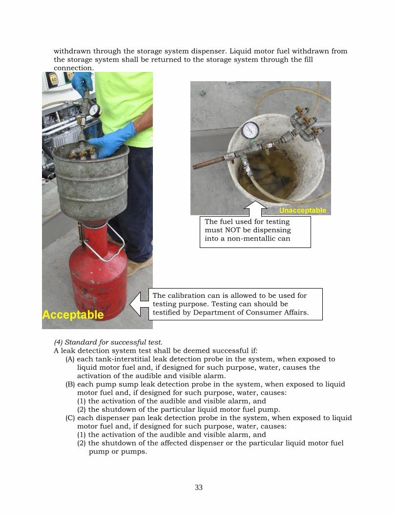
33
withdrawn through the storage system dispenser. Liquid motor fuel withdrawn from the storage system shall be returned to the storage system through the fill connection.
(4) Standard for successful test. A leak detection system test shall be deemed successful if:
(A) each tank-interstitial leak detection probe in the system, when exposed to liquid motor fuel and, if designed for such purpose, water, causes the activation of the audible and visible alarm.
(B) each pump sump leak detection probe in the system, when exposed to liquid motor fuel and, if designed for such purpose, water, causes: (1) the activation of the audible and visible alarm, and (2) the shutdown of the particular liquid motor fuel pump.
(C) each dispenser pan leak detection probe in the system, when exposed to liquid motor fuel and, if designed for such purpose, water, causes: (1) the activation of the audible and visible alarm, and (2) the shutdown of the affected dispenser or the particular liquid motor fuel
pump or pumps.
The fuel used for testing must NOT be dispensing into a non-mentallic can
The calibration can is allowed to be used for testing purpose. Testing can should be testified by Department of Consumer Affairs.

34
(D) each electronic line leak detector in the system, upon detection of liquid motor fuel leak, causes: (1) the activation of the audible and visible alarm, and (2) the shutdown of the particular liquid motor fuel pump or a significant
restriction of liquid motor fuel flow. (E) each mechanical line leak detector in the system, upon detection of a liquid
motor fuel leak, causes the shutdown of the liquid motor fuel pump or the stopping of liquid motor fuel flow at any rate exceeding 3 gallons per hour.
(5) Restoration of system. Upon successful completion of a leak detection system functionality test, liquid motor fuel storage and dispensing system, including the leak detection system, shall be returned to normal operation and checked to ensure that it is in good working order.
4.6.6 Fire extinguishing system test The test shall be in accordance with procedures prescribed by the commissioner. 4.6.7 Emergency tank and piping system test The commissioner may require that a tank and piping system be precision tested or pressure tested to determine the condition of the tank or piping. Such tests shall be conducted at the owner’s risk by his or her representative. Storage systems that may contain liquid motor fuel or combustible vapor shall not be tested pneumatically. 4.6.8 Periodic tank and piping test Any existing underground single-walled liquid motor fuel storage tanks previously approved by the department or any existing underground tanks that is not provided with an approved leak detection system must be precision tested at least once every 5 years. Inspection and testing shall be conducted at the owner’s risk by his or her representative before a representative of the department. Overfill prevention devices shall be inspected and tested for proper operation at least once every 2 years by a W-16 Certificate of License holder. Prior to being placed into services, initial tank test and initial piping test must be performed. Leak detection functionality test, overfill prevention devices, fire extinguishing system test and emergency tank and piping system test must be performed before starting operation. Leak detection functionality test, fire extinguishing system test, and precision test must be performed periodically at the owner's risk, before a representative of the Fire Department: at least once every 2 years for leak detection functionality test and at least once every 5 years for fire extinguishing system test and precision test. Records of such inspection shall be maintained on the premises for a minimum of 5 years.

35
PART 5. ABOVEGROUND LIQUID MOTOR FUEL STORAGE TANK 5.1 Contents and Tank Capacities Limitation (FC 2206.2.2; FC2206.2.3 ) 1. No flammable liquid motor fuel is allowed to be stored in aboveground tanks. Only
diesel motor fuel is allowed to be stored in the aboveground tanks of private dispensing facilities.
2. It is unlawful to store liquid motor fuel in aboveground tanks within any building or structure.
3. Combustible liquid motor fuel must not be stored in aboveground tanks, except at a fleet liquid motor fuel-dispensing facility complying with the FDNY requirements.
4. The capacity of an aboveground tank installation shall not exceed 4,000 gallons. The total storage capacity at a facility in both aboveground and underground tanks shall not exceed 40,000 gallons of liquid motor fuel. Each tank shall have a separate fill line and a separate vent line that are separate from the fill and vent lines of other tanks.
Exception: When approved, individual tanks may exceed 4,000 gallons, but shall not exceed 12,000 gallons.
Examples of aboveground motor fuel-dispensing facility
5.2 Design and Constructions of Motor Fuel Tank Installations (FC2206.2.3.3;FC2206.2.3.4;FC2206.2.3.5) The manufacture of the tanks and all related equipments must be UL certificated. Only approved tanks shall be used. Tanks shall be placed on an approved base slab. The surface of such base slab must be a minimum of 6 inches above the level of the surrounding area to permit visual inspection. Tanks shall be adequately supported and anchored to the base slab to withstand uplifting by surface water and flooding.
Single-wall storage tank must be provided with drainage control or shall be diked.

36
Tank connections shall be designed and located so as to: i).Minimize the maneuvering necessary to position a cargo tank to make the
delivery. ii).Minimize obstructing a public right of way or motorists’ view of roadways, or
impeding the movement of motor vehicles or pedestrians, during deliveries. iii).Provide connections by means of approved liquid and vapor-tight
connections. Tanks shall be provided with an approved liquid level-indicating device. The liquid level-indicating device shall be accessible to the delivery operator. Liquid level indicating devices shall be designed and constructed to be vapor-and-liquid tight. 5.3 Location Requirements (FC312.2; FC2206.2.4;FC3404.2.9.5.2; FC3404.2.9.6.5) 5.3.1 Locations Tanks shall be located as follows:
i.) At a location that will not obstruct or interfere with any means of egress or department access.
ii.) Tanks must not be installed under electrical transmission lines, bridges, or public highways.
iii.) Minimum separation requirements for aboveground tanks at fleet motor fuel-dispensing facilities: Individual tank capacity 4,000 gallons > 4,000 gallons Subway grating, entrance or exit
25 feet 25 feet
Nearest building 15 feet 25 feet Lot line 15 feet 25 feet Public street or private road 5 feet 15 feet Other tanks 3 feet 3 feet
The separation between tanks containing stable liquids shall be in accordance with Table 2.3.2.2.1 of NFPA 30. Where tanks are in a diked area containing Class I or II liquids, or in the drainage path of Class I or II liquids, and are compacted in three or more rows or in an irregular pattern, the commissioner may require greater separation than specified in Table 2.3.2.2.1 of NFPA 30 or other means to make tanks in the interior of the pattern accessible for firefighting purposes. The separation between tanks containing unstable liquids shall not be less than one-half the sum of their diameters.
Exception: Tanks used for storing Class IIIB liquids are allowed to be spaced 3 feet apart unless within a diked area or drainage path for a tank storing Class I or II liquids.
5.3.2 Protection 1. Aboveground tanks for the storage of liquid motor fuel must be safeguarded in an
approved manner by the agencies having jurisdiction from public access or unauthorized entry.
2. Guard posts or other approved means must be provided to protect aboveground tanks against impact by a motor vehicle unless the tank is listed as a protected

37
aboveground tank with vehicle impact protection. The guard posts must comply with the following requirements:
An example of guard posts
3. Where protected aboveground tanks, piping, electrical conduit or dispensers are subject to vehicular impact, they shall be protected therefrom, either by having the impact protection incorporated into the system design in compliance with the impact test protocol of UL 2085, or by meeting the requirements of guard posts, or where necessary, a combination of both. Where posts or other approved barriers are provided, they shall be independent of each aboveground tank.
5.4 Drainage Control, Diking and Secondary Containment (DEC 613.3(C)(6);FC2206.5; FC3404.2.9.6.4; FC3404.2.9.6.8;FC3404.2.10) The area surrounding a tank or group of tanks shall be provided with drainage control or shall be diked to prevent accidental discharge of liquid from endangering adjacent tanks, adjoining property or reaching waterways. The area shall be in compliance with the following requirements.
Guard posts should be 1. Constructed of steel not less than 4 inches in diameter and concrete filled. 2. Spaced not more than 4 feet between posts on center. 3. Set not less than 3 feet deep in a concrete footing of not less than a 15-inch
diameter. 4. Set with the top of the posts not less than 3 feet above ground. 5. Located not less than 3 feet from the protected object.

38
Exceptions: 1. For tanks having a capacity of less than 10,000 gallons, the commissioner
may modify these requirements based on an approved technical report which demonstrates that such tank or group of tanks does not constitute a hazard to other tanks, waterways or adjoining property, after consideration of special features such as topographical conditions, nature of occupancy and proximity to buildings or structures on the same or adjacent property, capacity, and construction of proposed tanks and character of liquids to be stored, and nature and quantity of private and public fire protection provided.
2. Drainage control and diking is not required for listed secondary containment tanks.
5.4.1 Diked areas The volumetric capacity of the diked area shall not be less than the greatest amount of liquid that can be released from the largest tank within the diked area. The capacity of the diked area enclosing more than one tank shall be calculated by deducting the volume of the tanks other than the largest tank below the height of the dike. Diked areas shall be kept free from combustible materials, drums and barrels. Diked areas containing multiple tanks shall be subdivided in accordance with NFPA 30. Piping shall not pass through adjacent diked areas or impounding basins, unless provided with a sealed sleeve or otherwise protected from exposure to fire. Pumps, manifolds and fire protection equipment or controls shall not be located within diked areas or drainage basins or in a location where such equipment and controls would be endangered by fire in the diked area or drainage basin. Piping above ground shall be minimized and located as close as practical to the shell of the tank in diked areas or drainage basins. Equipments and controls must be fire-proof and all electrical equipments must be grounded.
Exceptions: 1. Pumps, manifolds and piping integral to the tanks or equipment being served
which is protected by intermediate diking, berms, drainage or fire protection, such as water spray, monitors or resistive coating.
2. Fire protection equipment or controls which are appurtenances to the tanks or equipment being protected, such as foam chambers or foam piping and water or foam monitors and hydrants, or hand and wheeled extinguishers.
All dike walls shall be of steel or reinforced concrete, designed to be liquid tight and to withstand a full hydraulic head, and constructed to provide access to and from the diked area. Where stairways or other means are required to provide such access, they shall be constructed of steel. No dike wall shall be higher than 60 percent of the tank height. 5.4.2 Secondary containment system for aboveground tanks A secondary containment system must be installed around any aboveground petroleum storage tank which:
(a) could reasonably be expected to discharge petroleum to the waters of the state, or (b) which has a capacity of 10,000 gallons or more.
The secondary containment system must be constructed so that spills of petroleum and chemical components of petroleum will not permeate, drain, infiltrate or otherwise escape to the ground waters or surface waters before cleanup occurs. The secondary
39
containment system may consist of a combination of dikes, liners, pads, ponds, impoundments, curbs, ditches, sumps, receiving tanks and other equipment capable of containing the product stored. Construction of diking and the storage capacity of the diked area must be in accordance with NFPA No. 30, section 2-2.3.3. If soil is used for the secondary containment system, it must be of such character that any spill onto the soil will be readily recoverable and will result in a minimal amount of soil contamination. Storm water which collects within the secondary containment system must be controlled by a manually operated pump or siphon, or a gravity drain pipe which has two manually controlled dike valves, one on each side of the dike. All pumps, siphons and valves must be properly maintained and kept in good condition. If gravity drain pipes are used, all dike valves must be locked in a closed position except when the operator is in the process of draining clean water from the diked area. Ideally, the floor of an aboveground storage tank should be sloped to a collection sump. Storm water or any other discharge at a facility must be uncontaminated and free of sheen prior to discharge. Storm water which is contaminated must be treated to reduce petroleum concentration to 15 parts per million or less and to remove any visible sheen prior to discharge. Additional requirements may be imposed under 6 NYCRR Parts 751-758 for protection of the state's waters. The secondary containment systems shall be monitored either visually or automatically. Enclosed secondary containment systems shall be provided with emergency venting. A spill container having a capacity of not less than 15 gallons shall be provided for each fill connection. For tanks with a top fill connection, spill containers shall be noncombustible and shall be fixed to the tank and equipped with a manual drain valve that drains into the primary tank. For tanks with a remote fill connection, a portable spill container shall be allowed.

40
PART 6. FUEL-DISPENSING SYSTEM AND AREA FC2203.1; FC2203.2; FC2204.1;FC2206.7; FC2203.2
6.1 Location of Dispensing Devices 6.1.1 Outdoor dispensing devices When installed outdoors, dispensing devices shall be located as follows:
1. 10 feet or more from lot lines and building or structure openings. 2. 10 feet or more from buildings or structures having combustible exterior wall
surfaces or buildings or structures having noncombustible exterior wall surfaces that are not part of a 1-hour fire-resistance-rated assembly or buildings or structures having combustible overhangs.
Exception: Canopies constructed in accordance with the construction codes, including the Building Code, providing weather protection for the motor fuel dispensers.
3. Such that all portions of the vehicle being fueled will be on the premises of the automotive liquid motor fuel-dispensing facility.
4. Such that the nozzle, when the hose is fully extended, will not reach within 5 feet of building or structure openings.
5. 20 feet or more from fixed sources of ignition. 6. 25 feet or more from the nearest subway grating, entrance or exit.
6.1.2 Indoor dispensing devices When installed inside a building or structure, the dispensing area shall be located at street level, with no dispenser located more than 50 feet from an exit or entrance to the building or structure used by motor vehicles. 6.2 Fuel-Dispensing Systems (FC2206.7) Electrical equipment, dispensers, hoses, nozzles and submersible or subsurface pumps used in fuel-dispensing systems shall be UL or approved listed. 6.2.1 Fixed pumps required Liquid motor fuel shall be transferred only from the top of the tank by means of fixed pumps designed and equipped to allow control of the flow and prevent leakage or accidental discharge. Only one vehicle may be fueled at a time. Fuel dispensing from a location remote from the tank may be permitted when approved by the commissioner. Sump pumps shall be compatible with the liquid motor fuel being transferred, liquid-tight, and accessible for inspection. Prefabricated sump pumps shall be approved. Liquid motor fuel shall not be dispensed by gravity from tanks, drums, barrels or similar containers. Liquid motor fuel shall not be dispensed by a device operating through pressure within a storage tank, drum or container. 6.2.2 Mounting of dispensers Dispensing devices, except those installed on top of a protected aboveground tank that qualifies as vehicle-impact resistant, shall be protected against physical damage by mounting on a concrete island 6 inches or more in height, or shall otherwise be suitably protected in accordance with guard posts or other approved means. Dispensing devices

41
shall be installed and securely fastened to their mounting surface in accordance with the dispenser manufacturer’s instructions. Dispensing devices installed indoors shall be located in an approved position not in a direct line with vehicular traffic. Openings in floors beneath automotive liquid motor fuel-dispensing facilities located inside buildings or structures shall be sealed. If a dispenser pan is installed beneath a dispenser, it shall be approved, compatible with the liquid motor fuel, liquid-tight, accessible for inspection, no larger than necessary, and installed solely for the purpose of collecting any liquid motor fuel leaking from the dispenser. The dispenser pan shall not be used to collect liquid motor fuel discharged from defective piping. The dispenser pan shall be backfilled up to not less than 6 inches above any nonmetallic piping and shall not interfere with the operation of any safety device. 6.2.3 Dispenser emergency valve An approved emergency shutoff valve designed to close automatically in the event of a fire or impact shall be properly installed in the liquid supply line at the base of each dispenser supplied by a remote pump. The valve shall be installed so that the shear groove is flush with or within 0.5 inch of the top of the concrete dispenser island and there is clearance provided for maintenance purposes around the valve body and operating parts. The valve shall be installed at the liquid supply line inlet of each overhead-type dispenser. Where installed, a vapor return line located inside the dispenser housing shall have a shear section or approved flexible connector for the liquid supply line emergency shutoff valve to function. Emergency shutoff valves shall be installed and maintained in accordance with the manufacturer’s instructions, tested at the time of initial installation and tested at least yearly. 6.2.4 Dispenser hose Dispenser hoses shall be a maximum of 18 feet in length unless otherwise approved. Dispenser hoses shall be listed and approved. When not in use, hoses shall be reeled, racked or otherwise protected from damage. The length of the dispensing hose shall be such that at least 1 inch clearance between the hose and the ground is maintained when the nozzle is rested on its bracket. Dispensing hoses installed at aviation facilities, marine liquid motor fuel-dispensing facilities, and fleet vehicle liquid motor fuel-dispensing facilities shall be of an approved length. Dispenser hoses shall be equipped with a listed emergency breakaway device designed to retain liquid on both sides of a breakaway point. Such devices shall be installed and maintained in accordance with the manufacturer’s instructions. Where hoses are attached to hose-retrieving mechanisms, the emergency breakaway device shall be located between the hose nozzle and the point of attachment of the hose-retrieval mechanism to the hose.

42
6.2.5 Fuel delivery nozzles A listed automatic-closing-type hose nozzle valve without a latch-open device shall be provided for dispensers used for dispensing liquid motor fuel, except that a nozzle valve with a latch-open device may be installed and used at the following automotive liquid motor fuel-dispensing facilities:
1. Full service automotive liquid motor fuel-dispensing facilities. 2. Fleet automotive liquid motor fuel-dispensing facilities. 3. Dispensing of diesel fuel at self-service automotive liquid motor fuel-dispensing
facilities. Special requirements for nozzles. Where dispensing of liquid motor fuel is performed, a listed automatic-closing-type hose nozzle valve shall be used that incorporates all of the following features:
1. The hose nozzle valve shall be equipped with an integral latch-open device, when the use of such a device is authorized by this section.
2. When the flow of product is normally controlled by devices or equipment other than the hose nozzle valve, the hose nozzle valve shall not be capable of being opened unless the delivery hose is pressurized. If pressure to the hose is lost, the nozzle shall close automatically. Exception: Vapor recovery nozzles incorporating insertion interlock devices designed to achieve shutoff on disconnect from the vehicle fill pipe.
3. The hose nozzle shall be designed such that the nozzle is retained in the fill pipe during the filling operation.
4. The system shall include listed equipment with a feature that causes or requires the closing of the hose nozzle valve before the product flow can be
The nozzle must be provided WITHOUT a latch-open device in a self-serving motor fuel station.
Emergency Breakaway Device
the hose-retrieval mechanism

43
resumed or before the hose nozzle valve can be replaced in its normal position in the dispenser.
Control device. A control device shall be provided that will allow a liquid motor fuel pump to operate only when the dispensing nozzle is removed from its bracket on the dispenser and the switch on the dispenser is manually activated. The flow of liquid motor fuel shall automatically stop when the switch is deactivated or the nozzle returned to its bracket.
6.2.6 Vapor-balance systems
((FC2206.7.9 ) Dispensing devices incorporating provisions for vapor recovery shall be listed and labeled. When existing listed or labeled dispensing devices are modified for vapor recovery, such modifications shall be listed by report by a nationally recognized testing laboratory. The listing by report shall contain a description of the component parts used in the modification and the recommended method of installation on specific dispensers. Such report shall be made available for inspection by any department representative. Means shall be provided to shut down motor fuel dispensing in the event the vapor return line becomes blocked. An approved method shall be provided to close off the vapor return line from dispensers when the product is not being dispensed. 6.2.7 Emergency disconnect switches An approved, clearly identified and readily accessible emergency disconnect switch shall be provided at an approved location, to immediately shut down the transfer of fuel to the fuel dispensers in the event of a fuel spill or other emergency. An emergency disconnect switch for exterior fuel dispensers shall be located within 100 feet of, but not less than 20 feet from, the fuel dispensers. For interior fuel-dispensing operations, the emergency disconnect switch shall be installed at an approved location. An approved sign shall be posted on or immediately adjacent to such devices and should read: EMERGENCY FUEL SHUTOFF. Such emergency disconnect switches shall be of a type that is reset manually.

44
6.3 Supervision of the Dispensing of Liquid Motor Fuel (FC2204.2; FC2204.6; FC2204.7;FC2204.8;Rule 2204-01(c) The dispensing of liquid motor fuel at automotive liquid motor fuel-dispensing facilities shall be conducted under the supervision of a P-15 Certificate of Fitness (C of F) holder. It shall be unlawful to smoke or use or maintain an open flame in areas where fuel is dispensed. The engines of vehicles being fueled shall be shut off during fueling. Electrical equipment shall be installed, operated and maintained in accordance with the Electrical Code. Flammable liquid motor fuel shall not be dispensed into the fuel tanks of motor vehicles imported by ship to this country while on any pier, dock or wharf. 6.3.1 Self-service motor fuel-dispensing facilities The P-15 C of F holder’s primary function shall be to supervise, observe and monitor the dispensing of motor fuel. The P-15 C of F holder shall:
(a) prevent the dispensing of motor fuel into containers that do not comply with the requirements of FDNY,
(b) control sources of ignition, (c) take immediate action upon an accidental spill or release, (d) be ready to use a portable fire extinguisher, (e) activate the fixed fire extinguishing system, (f) call 911 if an emergency arises.
Nothing shall be construed to prohibit a P-15 C of F holder from engaging in other activities so long as such activities do not interfere with the P-15 C of F holder’s ability to supervise, observe and monitor the dispensing of motor fuel and other requirements of this chapter. Approved self-service devices, equipment and systems such as, but not limited to, card- operated and remote-preset types, are allowed at automotive liquid motor fuel-dispensing facilities. The P-15 C of F holder shall set the dispensing devices in the “off” position when not in use if such dispensing device can be activated without the P-15 C of F holder’s knowledge. (1) Control area A control area shall be located on the premises of every self-service automotive liquid motor fuel-dispensing facility. The control area shall be an interior or exterior enclosure to which the public has no access. The control booth shall be kept clean and orderly. The P-15 C of F holder shall be present within the control area while dispensing operations are conducted. The control area shall be designed and located so that the P-15 C of F holder stationed therein shall have a full, unobstructed clear view of dispensing operations, except that mirrors and/or an approved closed-circuit television installation may be provided to afford the P-15 C of F holder a clear view of dispensing operations when the view from the control area is partially or temporarily obstructed. The glass panels of the control booth shall be kept clean and unobstructed at all times. Access to the controls in the booth shall be kept unobstructed by equipment, merchandise or litter. For purposes of this section, the “clear” view provided by a closed-circuit television

45
installation shall mean that the image on the monitor shall be of such brightness and resolution as to allow ready identification of individuals and easy observation of activities at all times of day. Properly labeled manual switches that activate the fire extinguishing system and electrically disconnect the liquid motor fuel dispensing pumps shall be located adjacent to each other within the control area. Approved emergency controls shall be provided. A console that controls the self-service liquid motor fuel dispensers shall be provided within the control area and within 5 feet of the manual switches. An operating manual consisting of a copy of this section, emergency procedures, and facility operating procedures (including the operation of the fire extinguishing system) shall be maintained in the control booth. (2) Communications. A two-way voice communication system shall be installed to provide contact between the control area and each dispensing island. A telephone not requiring a coin to operate, or other approved clearly identified means to notify the department, shall be provided at the facility in an approved location. (3) Motor Fuel Dispensing (Rule 2204-01-(c)(6)(A); FC2707.4) Persons dispensing motor fuel at a self-service motor fuel-dispensing facility shall hold a valid driver’s license or be at least 18 years of age. The P-15 certified attendant or other facility personnel may require any member of the public to produce evidence of same. Permits to transport motor fuel in a portable container that larger than 2.5 gallons shall be required. Such permits shall be issued to a particular vehicle or marine vessel for such transportation. The P-15 certified attendant shall not dispense liquid motor fuel into a portable container in quantities requiring a permit unless the P-15 certified attendant verifies that the customer possesses all such permits. 6.3.2 Full service motor fuel-dispensing facilities (1)Operating instructions. Approved emergency controls shall be provided. Dispenser operating instructions shall be conspicuously posted in approved locations on every dispenser and shall indicate the location of the emergency controls. An approved emergency procedures sign shall be provided and posted. (2)Communications. A telephone not requiring a coin to operate or other approved, clearly identified means to notify the department shall be provided at the facility in an approved location.

46
PART 7. RECORD, MAINTENANCE AND REPORT (FC2201.9; FC2206.2.1.1;FC2206.9.3; FC2205.2; DEC613.8) 7.1 Inventory Control for Underground Tanks (1) Daily inventory records Accurate daily inventory records shall be maintained and reconciled for underground liquid motor fuel storage tanks for indication of possible leakage from tanks and piping. Inventory reconciliation shall be in accordance with the regulations of the New York State Department of Environmental Conservation as set forth in 6 NYCRR Part 613. The records shall be kept at the premises and be made available for inspection by any representative of the department. Records shall include daily reconciliation between sales, use, receipts and inventory on hand. Where there is more than one system consisting of tanks serving separate pumps or dispensers for a product, the reconciliation shall be maintained separately for each tank system. A consistent or accidental loss of product shall be immediately reported to the commissioner. (2) Maintenance log book. A maintenance log shall be kept on the premises for inspection by any Department representative. Such log shall list all P-15 certified attendants and other persons on the premises who hold certificates of fitness, with their numbers and expiration dates. Entries shall be made in such log book of the daily inspections required by this section, any maintenance or repair of any system, and any fires, spills or other unusual occurrences. (3) Daily inspections. The P-15 C of F holder shall conduct an inspection of the facility at least on a daily basis, and document such inspection in the maintenance log book. The inspection shall verify that:
(A) The fire extinguishing system is properly pressurized, nozzles are clear and unobstructed, and heat detectors are undamaged and unobstructed.
(B) Portable fire extinguishers have been serviced and have adequate pressure. (C) The fire extinguishing system remote manual pull station and the pump
shutdown are clear of obstructions. (D) Leak detection systems and other alarms are in good working order. (E) Emergency procedures signage is posted, unobstructed and legible. (F) Required lighting is in good working order. (G) Any mirrors and/or approved closed-circuit television used to monitor
dispensing operations are in good working order. (H) The voice communications system is in good working order.

47
Example of the maintenance log book
NYC Daily Inspection Log ____________________________ Address _______________________________ Month _____________
DATE FSS
CYLINDERS PRESSURE
EMERGENCY SHUT-OFF
SWITCHES & BEACON LIGHT
SENSORS &
NOZZLES
EMERGENCY RESPONSE SIGNAGES
ILLUMINATION LIGHTS
PORTABLE EXTINGUISHERS
INTERCOM MIRRORS/CCTV
COMMENTS
1 2 3 4 5 6 7 8 9 10 11 12 13 14 15 16 17 18 19 20 21 22 23 24 25 26 27 28 29 30 31

48
7.2 Inspections and Tests Records Records of all inspections and testing shall be kept in a bound log book or other approved recordkeeping, maintained on the premises for a minimum of 5 years, and made available for inspection by a representative of the department. Automatic-closing emergency shutoff valves (shear valves) shall be checked not less than once per year by manually tripping the hold-open linkage. In addition, the leak detection system shall be inspected daily for proper operation and tested at least once every 2 years by a person holding a certificate of license. Such test shall confirm that all leak detection equipment and associated alarms are in good working order. 7.3 Equipment Maintenance Automotive liquid motor fuel-dispensing facility equipment shall be maintained in good working order at all times. Where maintenance to dispensing devices becomes necessary and such maintenance could allow the accidental release or ignition of liquid, the following precautions shall be taken:
1. Only persons with a W-16 certificate of license and knowledgeable in performing the required maintenance shall perform the work.
2. Electrical power to the dispensing device and pump serving the dispenser shall be shut off at the main electrical disconnect panel before maintenance begins.
3. The emergency shutoff valve at the dispenser, where installed, shall be closed before maintenance begins.
4. Vehicle traffic and unauthorized persons shall be prevented from coming within 12 feet of the dispensing device before and during maintenance.
7.4 Reporting of Spills and Discharges The results of any inventory record, test or inspection which shows a facility is leaking must be reported to Bulk Fuel Safety Unit of FDNY and Department of Environmental Conservation (DEC) within 2 hours of the discovery. All petroleum spills that occur within New York State (NYS) must be reported to the NYS Spill Hotline (1-800-457-7362) within 2 hours of discovery, except spills which meet ALL of the following criteria:
1. The quantity is known to be less than 5 gallons; and 2. The spill is contained and under the control of the spiller; and 3. The spill has not and will not reach the State's water or any land; and 4. The spill is cleaned up within 2 hours of discovery.
A spill is considered to have not impacted land if it occurs on a paved surface such as asphalt or concrete. A spill in a dirt or gravel parking lot is considered to have impacted land and is reportable. More details on notification and reporting requirements can be found in the document posted by the Department of Environmental Conservation (http://www.dec.ny.gov/docs/remediation_hudson_pdf/1x1.pdf). (The spill responses can be referred to http://www.dec.ny.gov/chemical/8692.html)

49
PART 8. RECONDITIONING, REPAIR AND OUT OF SERVICE TANKS 8.1 Reconditioning an Underground Steel Tank DEC614.6; 8.1.1 Manufacturer's guarantee An underground steel tank may be reconditioned by installing an interior coating (lining) under the direction of the lining manufacturer or a certified representative. The manufacturer or representative must guarantee to the owner in writing that the coating will not fail, crack, separate or deteriorate and the tank will not leak the product specified in storage for a period of 10 years. A copy of the guarantee (e.g. integrity report) must be kept by the owner for the life of the tank. 8.1.2 Structural requirements
(1) A steel tank may be lined with a coating only if it meets the following structural conditions:
i. it has a design shell thickness of seven gauge or more; ii. the tank has a minimum metal thickness of 1/8 inch at holes after reaming; iii. the tank has no open seam or split; iv. the tank has less than 10 holes with none larger than 1/2 inch in diameter; v. the tank meets all standards for structural soundness of the lining
manufacturer. (2) A tank which fails to meet all of the requirements of paragraph (1) of this
subdivision must be permanently closed. (3) To determine adherence to the requirements of paragraph (1) of this subdivision,
the entire interior surface of the tank must be tapped with a ballpeen hammer for soundness or inspected using other equivalent or superior nondestructive methods. Weak areas, holes and seams must be ballpeen hammered (before and after sandblasting) to obtain structurally sound edges. Holes and seams must be reamed until the edges of the opening are a minimum of 1/8 inch thick.
8.1.3 Preparation of tank interior Prior to repair, a tank must be cleaned in accordance with generally accepted practices. Sludge accumulation on the bottom of the tank must be removed, transported and disposed of in a manner consistent with all State and Federal requirements for solid waste disposal. The entire internal tank surface must be sandblasted completely free of scale, rust and foreign matter. Following sandblasting, the entire surface must be brushed and vacuumed such that the surface when viewed without magnification is free of all moisture and foreign matter. All perforations must be tightly plugged with boiler plugs or screws made of noncorrodible plastic. Boiler plugs or screws must be covered with a laminate of resin and fiberglass cloth which overlaps all sides of the plug with a minimum of 6 inches and has a minimum area of 144 square inches. Prior to applying the coating material, a 10-gauge steel plate which covers a minimum of 144 square inches must be installed and centered under the fill tube and gauging tube. The plate must be bonded to the interior surface of the tank.

50
8.1.4 Coating (lining) specifications (1) Any noncorrodible epoxy based resins, isophthalic polyester-based resins or
equivalent coating may be used for reconditioning a steel tank if the coating is of sufficient thickness, density and strength to form a hard impermeable shell which will not leak, crack, wear, soften or separate from the interior surface of the tank.
(2) The coating when applied to properly prepared steel must maintain a permanent bond to the tank.
(3) The coating's coefficient of thermal expansion must be compatible with steel so that stress due to temperature changes will not be detrimental to the soundness of the coating.
(4) The coating must be chemically compatible with petroleum products and product additives.
8.1.5 Application of coating (1) The coating must be applied and cured in strict accordance with manufacturer's
specifications. (2) The coating must be applied as soon as possible but not later than 8 hours after
sandblasting and cleaning of the internal surface. Visible rust, moisture or foreign material must not be present.
8.1.6 Tank closings (1) If the tank has a manway, the manway cover gasket must be replaced with a new one
before resealing. (2) If the tank does not have a manway and an opening has been cut, the tank must have
a manway properly welded in place prior to beginning work or the tank must be sealed as follows:
i. A 1/4-inch thick steel cover plate, rolled to the contour of the tank exterior must be made to overlap the hole at least two inches on each side (e.g., should measure at least 26" x 26" if the opening was cut 22" x 22").
ii. The cover must be used as a template to locate 3/4-inch diameter holes on five-inch centers, one inch from the edge of the cover.
iii. The cover plate must be sandblasted and both sides and the entire inside surface of the plate must be covered with coating material to act as a gasket.
iv. Before the coating on the cover cures, the cover must be fastened to the tank using 1/2-inch minimum diameter bolts. The bolt shafts are to be placed through the holes from the inside of the tank and held in place by spring clips, then fastened with lock washers and nuts which have been dipped in a seam sealer.
v. After being bolted to the tank, the cover plate and surrounding tank surface must be properly sandblasted, coated with coating material and allowed to cure before backfilling the hole.
8.1.7 Tank tightness testing Following closure of the tank and before backfilling, the relined tank must be given a tightness test (i.e. hydrostatic test) and a test report must be sent to the department. 8.2 Repair or Alteration of Tanks and Piping (FC3404.2.7.6; FC3404.2.7.10.1; DEC614.6;DEC614.12; FC3404.2.7.6) The repair or alteration, including welding, cutting and hot tapping of storage tanks and piping that have been placed in service, shall be in accordance with NFPA 30. Hot

51
tapping shall only be permitted with the approval of the commissioner. Leaking tanks shall be promptly emptied, repaired and returned to service, sealed in place or removed.
Repairing and reconditioning of aboveground storage tanks 8.2.1 Cleaning of tank prior to repair (1) Prior to repair, a tank must be cleaned in accordance with generally accepted
practices. Wash water must not be discharged to the waters of the State if the discharge would contravene the standards of DEC Part 701, 702 or 703 of this Title.
(2) Sludge which has accumulated on the bottom of the tank must be removed, transported and disposed of in a manner consistent with all applicable State and Federal requirements for solid waste disposal.
8.2.2 Coating (lining) specifications (1) Before doing the re-lining task, the tank must be examinated by the engineer of
record who will attest to the conditions of the tank for re-lining. Such a notification should be sent to the Bulk Fuel Safety Unit of FDNY.
(2) Any noncorrodible epoxy-based resins, isophthalic polyester-based resins or equivalent coating which is bonded firmly to the interior surfaces may be used as a coating to protect a tank from future corrosion.
(3) The coating must be applied as soon as possible, but not later than eight hours after sandblasting and cleaning of the internal surface. Visible rust, moisture or foreign matter must not be present.
(4) The coating must be of sufficient thickness, density and strength to form a hard impermeable shell which will not crack, soften or separate from the interior surface of the tank. The coating when applied to properly prepared steel must maintain a permanent bond to the tank.
(5) The coating's coefficient of thermal expansion must be compatible with steel so that stress due to temperature changes will not be detrimental to the soundness of the coating.
(6) The coating must be chemically compatible with petroleum products and product additives.
(7) The coating material must be applied and cured in strict accord with manufacturer's specifications.
(8) The re-lining of the tanks must be supervised by a W-16 Certificate of License holder and an affidavit provided to the Bulk Fuel Safety Unit of the Fire Department that the lining was completed under his supervision.
8.2.3 Inspection of coating The coating must be checked for blisters, air pockets and electrically tested for pinholes. The coating thickness must be checked with an Elcometer Thickness Gauge or equivalent and the hardness checked with a Barcol Hardness Tester or equivalent to assure compliance with manufacturer's specifications. Any defects must be repaired. An interior coating must be installed under the direction of the lining manufacturer or a certified representative. The manufacturer or representative must guarantee to the owner in writing that the coating will not leak the product specified in storage and the lining will not deteriorate in any way for a period of 10 years. A copy of the guarantee must be kept by the owner for the life of the tank.

52
8.3 Out of Service Tanks (FC3404.2.13 )
8.3.1 Underground out of service tanks Underground tanks not used for a period of 30 days or more shall be removed from the premises or safeguarded in compliance with the following requirements:
1. Flammable or combustible liquids shall be removed from the tank and connecting piping.
2. The tank and connecting piping shall be rendered free of flammable and combustible vapors using an inert gas.
The special regulations for the tanks which are not used for a period of 30 days to 364 days:
1. Except for any active fire extinguishing system piping, the tank and connecting piping, including fill line, gauge opening, vapor return and pump connection, shall be capped or plugged and secured from tampering and the fill connection covered with concrete.
2. Vent lines shall remain open and be maintained in accordance with the regulations of normal venting and emergency venting.
The special regulations for the tanks which are not used for a period of 1 year or more:
1. All tanks and connecting piping, including fire extinguishing system lines, fill line, gauge opening, vapor return and pump connection, shall be disconnected, capped or plugged and secured from tampering, and the fill connection sealed with concrete to prevent its use.
2. The tank shall be filled completely with an approved, inert solid material. 8.3.2 Aboveground out of service tanks Aboveground tanks not used for a period of 30 days or more shall be removed from the premises or safeguarded in compliance with the following requirements:
1. Tank and connecting piping shall be safeguarded. 2. The tank shall be protected from flotation in accordance with good engineering
practice. Aboveground tanks that have been out-of-service for a period of 1 year or more shall be removed from the premises or sealed in place in compliance with the following requirements:
1. Flammable and combustible liquids shall be removed from the tank and connected piping.
2. The tank and connecting piping shall be rendered free of flammable and combustible vapors using an inert gas.
3. All piping, including fire extinguishing system lines, fill line, gauge opening, vapor return and pump connection, shall be disconnected, capped or plugged and secured from tampering, and the fill connection sealed with concrete to prevent its use.
4. The tank shall be adequately protected from flotation in accordance with good engineering practice.
5. The tank shall be stenciled with the date that it was sealed in place.

53
8.4 Removal of Tanks (FC3404.2.14 )
Tanks and piping shall be disposed of lawfully. Removal of aboveground and underground tanks shall be in compliance with the following requirements:
1. Flammable and combustible liquids shall be removed from the tank and connecting piping.
2. The tank and connecting piping shall be rendered free of flammable and combustible vapors using an inert gas.
3. Piping at tank openings shall be disconnected. 4. Piping shall be removed from the premises.
Exception: Piping may be sealed in place where the commissioner determines that removal is not practical. Sealed in place piping shall be capped and safeguarded by filling with concrete or other approved material, and the fill connection removed from the fill pipe.
5. Tank openings shall be capped or plugged, leaving a 0.125-inch to 0.25-inch-diameter opening for pressure equalization.
6. Tanks shall be removed from the premises. 7. Tanks and piping shall be disposed of lawfully.

54
PART 9. EMERGENCY PLAN AND FIRE CONTROL (NFPA 30A 9.2.5.1; FC2205.5; FC2205.7;FC2206.8; FC2206.9.4; Rule 2204-01(c)(3)(C)) 9.1 Control of Ignition, Brush and Debris Smoking materials, including matches and lighters, must not be used within 20 ft of areas used for fueling, servicing fuel system of internal combustion engines, or receiving or dispensing of Class I and Class II liquids. The motors of all equipment being fueled must be shut of during the fueling operation except for emergency generators, pumps and so forth, where continuing operation is essential. Brush, grass, vines or other vegetation and combustible waste shall be kept not less than 10 feet from the tank and dispensing location. 9.2 Fire Extinguishers Approved portable fire extinguishers with a minimum rating of 40-B:C shall be provided and located such that an extinguisher is not less than 20 feet but not more than 75 feet from pumps, dispensers or storage tank fill-pipe openings. In addition to the portable fire extinguishers required to be provided in the dispensing area, 2 portable fire extinguishers with at least a 40-B:C rating shall be provided within the control booth.
Fire extinguishers must be used in accordance with the instructions painted on the side of the extinguisher. They clearly describe how to use the extinguisher in case of an emergency. The Certificate of Fitness holder should become familiar with the instructions for the extinguisher at his/her work site. When it come to using a fire-extinguisher just remember the acronym P.A.S.S. to help make sure you use it properly. P.A.S.S. stands for Pull, Aim, Squeeze, Sweep. An example of these instructions is depicted in the picture. All fire extinguishers must be installed so that the top of the extinguisher is not more than 5 ft above the floor and the clearance between the bottom of the extinguisher and the floor is not less than 4 in. In other words, no fire extinguisher is allowed to be on the floor.

55
9.2.1 Different types of fire extinguishers
The Certificate of Fitness holder must be familiar with the different types of fire extinguishers available at the work site. The Certificate of Fitness holder must know how to operate the extinguishers in a safe and efficient manner. The Certificate of Fitness holder must also know the difference between the various types of extinguishers and when they may be used. A description of the classes of fires and the appropriate extinguishers are described below.
Class A fires are caused by ordinary combustible materials (such as wood, paper, and cloth). To extinguish a Class A fire, these extinguishers utilize either the heat-absorbing effects of water or the coating effects of certain dry chemicals.
Class B fires are caused by flammable or combustible liquids and gases such as oil, gasoline, etc. To extinguish a Class B fire, the blanketing-smothering effect of oxygen-excluding media such as CO2, dry chemical or foam is most effective.
Class C fires involve electrical equipment. These fires must be fought with fire extinguishers that do not conduct electricity. Foam and water type extinguishers must not be used to extinguish electrical fires. After shutting off the electrical equipment, extinguishers for Class A or B fires may be used.
Class D fires are caused by ignitable metals, such as magnesium, titanium, and metallic sodium, or metals that are combustible under certain conditions, such as calcium, zinc, and aluminum. Generally, water should not be used to extinguish these fires.
A multi-purpose dry chemical fire extinguisher may be used to extinguish more than 2 Classes fires. Examples of some fire extinguishers are shown below.
(1) The top of the fire extinguishers must not be more than 5 ft above the floor.
(2) The fire extinguishers must be accessible and unobstructed.
The bottom of the extinguisher must be at least 4 in above the floor.
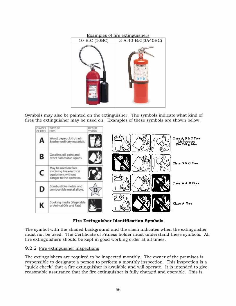
56
Examples of fire extinguishers
10-B:C (10BC) 3-A:40-B:C(3A40BC)
Symbols may also be painted on the extinguisher. The symbols indicate what kind of fires the extinguisher may be used on. Examples of these symbols are shown below.
Fire Extinguisher Identification Symbols
The symbol with the shaded background and the slash indicates when the extinguisher must not be used. The Certificate of Fitness holder must understand these symbols. All fire extinguishers should be kept in good working order at all times.
9.2.2 Fire extinguisher inspections
The extinguishers are required to be inspected monthly. The owner of the premises is responsible to designate a person to perform a monthly inspection. This inspection is a "quick check" that a fire extinguisher is available and will operate. It is intended to give reasonable assurance that the fire extinguisher is fully charged and operable. This is

57
done by verifying that it is in its designated place, that it has not been actuated or tampered with, and that there is no obvious or physical damage or condition to prevent its operation. The information of the monthly inspection record must include the date the inspection was performed, the person performing the inspection, and those portable fire extinguishers found to require corrective action. Such recordkeeping must be either attached to the extinguisher or on an inspection checklist maintained on file. Labels or markings indicating fire extinguisher use, or classification, or both shall be placed on the front of the fire extinguisher. At least once per year, all fire extinguishers must be maintained by a FDNY approved company and a W-96 Certificate of Fitness holder. 9.3 Fire Extinguishing System Where flammable liquid motor fuel is dispensed at an automotive liquid motor fuel-dispensing facility, the dispensing area shall be provided with a dry chemical fire extinguishing system designed, and the following requirements must be met:
1. The fire extinguishing system shall be designed to provide overhead protection of the dispenser area encompassed by a circle formed by the fully extended hose and nozzle on each fuel dispenser and both ends of the dispenser island.
2. The extinguishing agent containers shall be equipped with indicators to show whether the system is fully charged. Indicators shall be positioned to be easily read from grade.
3. The installation, alteration, testing and repair of the fire extinguishing system, including any maintenance or modification of the system, shall be performed by a person possessing a master fire suppression piping contractor license issued by the New York City Department of Buildings and certified in the installation, operation and maintenance of the specific fire extinguishing system.
4. Dispensers shall not be operated when the fire extinguishing system has discharged or is inoperative, except as authorized in writing by the department. The motor fuel-dispensing facility P-15 C of F holder shall immediately notify the department of system discharge or inoperability.
5. A performance test of the fire extinguishing system shall be performed at the time of installation in accordance with the approved design and installation documents, and such procedures as may be prescribed by the commissioner. Fire extinguishing systems shall be tested at least once every 5 years from the date of the first test of the initial installation. The test shall be in accordance with procedures prescribed by the commissioner.
6. Fire extinguishing systems at fleet vehicle automotive liquid motor fuel-dispensing facilities shall be monitored by an approved central station company.
Monthly inspection tag.

58

59
APPENDIX A. STAGE II VAPOR COLLECTION DECOMMISIONING NYS DEPARTMENT OF ENVIRONMENTAL CONSERVATION
Division of Air Resources STAGE II VAPOR COLLECTION DECOMMISSIONING CHECKLIST(JUNE 2011)
This form may be used to document the procedure used to decommission a Stage II Vapor Collection System.
A. Facility Information
Facility Name: ____________________________
Underground Storage Tank Program Identification #: _______________________
Facility Address (Street and City): ______________________________________
Owner: ______________________________ Phone: (______) _______- __________
B. Contractor Information
Contractor performing Stage II decommissioning: ____________________________
Business Address: _____________________________ Phone: (______) _______-_________
City, State: ___________________________ ZIP: _______________________
C. Decommissioning Actions
(a) Vapor collection piping:
Piping removed [if “yes” go on to (b)]?: Yes � No �
Piping purged of any liquid?: Yes � No �
Piping capped at dispenser end?: Yes � No �
Piping capped at tank end?: Yes � No �
(b) Liquid drop-out tank:
Liquid drop-out tank present [if “no” go on to (c)]?: Yes � No �
Liquid drop-out tank removed [if “no” go on to (c)]?: Yes � No �
Liquid in tank evacuated?: Yes � No �
Siphon line disconnected at submersible pump and capped?: Yes � No � Siphon not present �
(c) Hanging hardware:
Stage II hanging hardware replaced with non-Stage II equipment? : Yes � No �

60
(d) Vacuum pump:
Vacuum motor disabled or removed? : Yes � No � NA �
(e) Stage II Dispensing Instructions:
Decals with Stage II dispensing instructions removed? : Yes � No � NA �
(f) Leak test:
Leak test performed? : Yes � No �
Test report attached? : Yes � No �
D. Comments (use this section if you need to provide additional information)
E. Certification of Information Accuracy
The information presented herein is true and accurate to the best of my knowledge and I am authorized
to make this statement on behalf of this facility.
__________________________________________________________________________________
Signature of Owner �, Operator �, or Authorized Agent � Date ____________
Name:_______________________________________ Title: _______________________________
Business Address: ______________________________ Phone: (______)_______-___________
City, State: ____________________________________ ZIP: _____________________

61
APPENDIX B. FIRE CODE CHAPTER 9 FIRE PROTECTION SYSTEMS
FC 901 General
901.1 Scope. This chapter shall govern the design, installation, operation and maintenance, including inspection and testing, of fire protection devices, equipment and systems, and other fire protection measures for the control and extinguishment of fire.
901.1.1 General. Fire protection systems shall be designed, installed, operated and maintained in accordance with this chapter and the reference standards set forth in Table 901.6.
901.2 Design and installation documents. The commissioner may require design and installation documents and calculations to be submitted for review for all fire protection systems. Design and installation documents required or regulated by this code or the rules shall be submitted for review and approval prior to installation, and shall certify that the design complies with the requirements of this code and the rules. 901.3 Permits. Permits shall be required as set forth in Section 105.6. 901.4 Design and installation. Fire protection systems shall be designed and installed in accordance with Sections 901.4.1 through 901.4.5.
901.4.1 Required fire protection systems. Fire protection systems shall be designed and installed in accordance with the construction codes, including the Building Code, and, as applicable, this code and the rules, and the applicable referenced standards listed in this code. Required systems shall be extended or altered as necessary to maintain and continue protection whenever the building or structure is altered. Alterations to fire protection systems shall be performed in compliance with the requirements of this code, the rules, and the construction codes, as applicable. Buildings and structures shall be provided with such fire hose, portable fire extinguishers and other means of preventing and extinguishing fires as the commissioner may direct. 901.4.2 Fire protection systems not required by code. Any fire protection system or portion thereof not required by this code, the rules or the construction codes, including the Building Code, may be installed to provide partial or complete protection of a building or structure, provided such system meets the requirements of this code, the rules and the construction codes, including the Building Code, as applicable. Where the design and installation of such fire protection system is governed by this code or the rules, the commissioner may modify such requirements, consistent with the interests of fire safety, upon a determination that such modification will promote public safety by encouraging the installation of such systems. 901.4.3 Additional fire protection systems. Where the material or operation to be conducted in a particular occupancy gives rise to special hazards in addition to the normal hazards of the occupancy, or where the commissioner determines that access to the occupancy would unduly delay the ability of firefighting personnel to respond to the hazard, the commissioner may require additional safeguards. Such safeguards include, but shall not be limited to, the following: automatic fire detection systems, fire alarm systems, fire extinguishing systems, standpipe systems, or portable or fixed extinguishers. Fire protection equipment shall be installed in accordance with the construction codes, including the Building Code. 901.4.4 Prohibition of deceptive equipment. It shall be unlawful to install or maintain any device that has the physical appearance of fire protection equipment

62
but that does not perform the fire protection function, in any building, structure or premises where it may be confused with actual fire protection equipment. 901.4.5 Certificate of approval. The following fire protection devices, equipment and systems shall be of a type for which a certificate of approval has been issued in accordance with this code, or which was approved by the Department of Buildings or the Board of Standards and Appeals prior to the effective date of this section, unless such approval by the Department of Buildings or the Board of Standards and Appeals is amended or repealed by the commissioner:
1. Pre-engineered non-water fire extinguishing systems, including systems installed in connection with commercial cooking systems.
2. Prefabricated hoods and grease filters installed in connection with commercial cooking systems.
3. Fire department siamese connections, standpipe system hose outlets and pressure reducing valves.
4. Fire alarm system control panels. 901.5 Installation acceptance testing. Fire detection and alarm systems, fire extinguishing systems, private fire hydrant systems, yard hydrant systems, standpipe systems, fire pump systems, private fire service mains and all other fire protection systems and appurtenances thereto shall be subject to acceptance tests as set forth in the installation standards specified in this code. Where required by the construction codes, including the Building Code, this code or the rules, such tests shall be conducted, at the owner's risk, by his or her representative before a representative of the department.
901.5.1 Occupancy. It shall be unlawful to occupy any portion of a building or structure until any required fire detection system, fire alarm system, standpipe system and fire extinguishing systems have been tested and approved.
901.6 Maintenance. Fire protection systems shall be maintained in good working order at all times. Any fire protection system that is not in good working order shall be repaired or replaced as necessary to restore such system to good working order, or, where authorized by the Building Code, removed from the premises.
901.6.1 Standards. Fire protection systems shall be inspected, tested, serviced and otherwise maintained in accordance with this section, the rules and the referenced standards listed in Table 901.6.1. Where required by this section, such inspection, testing and maintenance shall additionally comply with the rules. Where applicable, the requirements of the reference standards listed in Table 901.6.1 shall be in addition to those requirements specified in the rules.
TABLE 901.6.1 FIRE PROTECTION SYSTEM MAINTENANCE STANDARDS SYSTEM
STANDARD
Portable fire extinguishers NFPA 10 Low, medium and high expansion foam systems NFPA 11 and NFPA 25 Carbon dioxide fire extinguishing system NFPA 12 Halon 1301 fire extinguishing systems NFPA 12A Foam water sprinkler and spray systems NFPA 16 and NFPA 25 Dry chemical fire extinguishing systems NFPA 17 Wet chemical fire extinguishing systems NFPA 17A Water based fire protection systems NFPA 25 Fire alarm systems NFPA 72 Water mist fire extinguishing systems NFPA 750 Clean agent fire extinguishing systems NFPA 2001

63
901.6.2 Records. Records of all system inspections, tests, servicing and other maintenance required by this code, the rules or the referenced standards shall be maintained on the premises for a minimum of 3 years and made available for inspection by any department representative.
901.6.2.1 Standpipe and sprinkler systems. In addition to those records required by NFPA 25, an approved card bearing the dates of each inspection, certificate of fitness number and signature of the certificate of fitness holder shall be posted on the premises near the main water supply control valve. A detailed inspection report relative to conditions of water supply, gravity and pressure tanks and levels therein, valves, risers, piping, sprinkler heads, hose valves, hose and nozzles, siamese connections, alarms, fire pumps, obstructions, and conditions of all other system equipment and appurtenances shall be completed monthly by the certificate of fitness holder. All defects or violations shall be noted on the inspection report.
901.6.3 Supervision. Inspection, testing, servicing and other maintenance of the following fire protection systems shall be performed under the personal supervision of a person holding a certificate of fitness.
1. Sprinkler systems. Exception: Buildings classified in Group R-3 occupancies.
2. Standpipe systems. 3. Foam fire extinguishing systems. 4. Fire alarm systems. 5. Private fire hydrant systems. 6. Yard hydrant systems. 901.6.3.1 Servicing of portable fire extinguishers. It shall be unlawful for any person engaged in the business of servicing portable fire extinguishers to service portable fire extinguishers without a portable fire extinguisher servicing company certificate. Any person that services portable fire extinguishers shall hold a certificate of fitness, except that a person training for such certificate of fitness may service portable fire extinguishers under the personal supervision of a certificate of fitness holder. Nothing in this section shall preclude portable fire extinguishers that are maintained on a premises for use at such premises from being serviced by the owner or occupant of the premises, or an employee of such owner or occupant, who possesses a certificate of fitness for portable fire extinguisher servicing and the tools, materials, equipment and facility necessary to perform such services. 901.6.3.2 Portable fire extinguisher sales. It shall be unlawful for any person to engage in the business of selling portable fire extinguishers door to door to owners of buildings or businesses for use on their premises without a portable fire extinguisher sales company certificate.
Exception: Sale to owners of Group R-2 and R-3 occupancy buildings. 901.6.3.3 Commercial cooking exhaust systems. It shall be unlawful for any person engaged in the business of inspecting and cleaning commercial cooking exhaust systems as required by the provisions of this code to perform such service without a commercial cooking exhaust system servicing company certificate. The inspection and cleaning of commercial cooking exhaust systems required by Section 904.11 shall be performed by a person holding a certificate of fitness. Nothing in this section shall preclude commercial cooking exhaust systems from being inspected and cleaned by the owner or occupant of the premises, or an employee of such owner or occupant, who possesses a certificate of fitness for

64
inspecting and cleaning commercial cooking exhaust systems and the tools, materials, and equipment necessary to perform such services in accordance with this section. 901.6.3.4 Smoke detector cleaning and testing. The cleaning and testing for smoke entry and sensitivity of smoke detectors installed in a defined fire alarm system shall be performed by a person holding a certificate of fitness for smoke detector maintenance. Such work shall be performed under the supervision and by employees of a person holding a smoke detector maintenance company certificate, except that such smoke detector cleaning and testing may be performed by an owner or occupant of the premises, or an employee of such owner or occupant, who possesses a certificate of fitness for smoke detector maintenance, and possesses the tools, instruments or other equipment necessary to perform such services in accordance this code and the rules. All other smoke detector maintenance shall be performed by a person possessing the requisite qualifications and experience, and any applicable license or certificate. 901.6.3.5 Central station fire alarm monitoring. It shall be unlawful for any person to operate a central station that monitors fire alarm systems and maintain transmitters in protected premises without a certificate of operation.
901.7 Out of service systems. Where a required fire protection system is out of service, the department shall be notified immediately and unless otherwise directed by the commissioner, either the building shall be evacuated or a fire watch shall be maintained by one or more persons holding a certificate of fitness for fire guard. Any other actions as the commissioner may direct in addition to or in lieu of such measures shall also be undertaken, until the fire protection system has been returned to service. Where utilized, fire guards shall be provided with at least one approved means for notification of the department and their only duty shall be to perform constant patrols of the protected premises and keep watch for fires.
901.7.1 Impairment coordinator. The building owner shall assign an impairment coordinator to comply with the requirements of this section. In the absence of a specific designee, the owner shall be considered the impairment coordinator. 901.7.2 Tag required. A tag shall be used to indicate that a system, or portion thereof, is out of service. 901.7.3 Placement of tag. The tag shall be posted at each fire department connection, system control valve, fire alarm control unit, fire alarm annunciator and fire command center, indicating which system, or part thereof, is out of service. The commissioner shall specify where the tag is to be placed. 901.7.4 Planned removal from service. The certificate of fitness holder and the impairment coordinator shall be made aware of and authorize the placing of systems out of service. Before authorizing such action the impairment coordinator shall:
1. Determine the extent and expected duration of the out of service condition. 2. Inspect the areas or buildings involved and assess the increased risks. 3. Make appropriate recommendations to the owner. 4. Notify the department and the responsible person designated by the owner to
issue hot work authorizations in accordance with Chapter 26. 5. Notify the central station and insurance carrier. 6. Notify the occupants in the affected areas. 7. Place out of service tags at all required and appropriate locations. 8. Maintain system in service until work is ready to begin.
901.7.5 Unplanned out of service condition. The certificate of fitness holder, impairment coordinator, and/or other person responsible for inspecting, maintaining

65
or supervising the operation of a fire protection system who observes a serious defect such as an empty tank, break or major leak in system water piping, inoperative or shut water supply valves, defective siamese connections, or complete or partial shut down of sprinkler and/or standpipe systems, 145 * FC901.7.7 added by Local Law No. 64 of 2009, effective 2/4/10. other than a shutdown for scheduled inspection, testing or maintenance, shall immediately report such condition to the owner of the building, and to the department. When a system fails or otherwise goes out of service, the certificate of fitness holder or the impairment coordinator shall take the actions set forth in Section 901.7.4. and such other actions necessary or appropriate to protect the occupants of the building and minimize property damage. When the certificate of fitness holder or other such person observes a minor defect or other condition not presenting a serious safety hazard, he or she shall report the defect or condition to the owner, and if the defect or condition is not corrected within 30 days, shall report it in writing to the department. 901.7.6 Restoring systems to service. When an out of service device, equipment or system is restored to normal working order, the impairment coordinator shall:
1. Conduct necessary inspections and tests to verify that the affected systems are operational.
2. Reserved. 3. Notify the department. 4. Notify the owner, central station, insurance carrier and occupants in the
affected areas. 5. Remove the out of service tags.
901.7.7 Out of service standpipe systems at construction sites.* The owner, fire safety manager and/or impairment coordinator shall take the following actions whenever a standpipe system at a construction site is out of service:
1. Immediately notify the department of any unplanned out of service condition, and otherwise comply with the requirements of Section 901.7.5.
2. Notify the department at least 24 hours prior to any planned removal of the standpipe system from service, and otherwise comply with the requirements of Section 901.7.4.
3. Ensure that a fire watch is continuously maintained in compliance with the requirements of Section 901.7 while the standpipe system is out of service.
4. Repair the standpipe system and return it to service in compliance with the requirements of Sections 901.6 and 901.7.6 and Section 3303.8.1 of the New York City Building Code. The construction site may continue to be occupied, and construction, demolition or alteration activities may continue, pending such repair and restoration to service, except:
4.1. As otherwise provided in Section 3303.8.1 of the New York City Building Code; and/or
4.2. As otherwise directed by the commissioner upon a determination that, in the absence of an operable standpipe system, the conduct of certain construction, demolition or alteration activities would be imminently perilous to life or property; and
4.3 That in no circumstance shall hot work be conducted on the construction site until such time as the standpipe system is restored to service and the standpipe alarm reactivated.

66
901.8 Tampering with or rendering equipment inoperable. Fire protection systems and related apparatus shall not be tampered with or rendered inoperable, except as set forth in Section 107.4.
FC 902 Definitions
902.1 Definitions. The following terms shall, for the purposes of this chapter and as used elsewhere in this code, have the meanings shown herein. ALARM NOTIFICATION APPLIANCE. A fire alarm system component, such as a bell, horn, speaker, light, text display or vibration device that issues an audible, tactile, and/or visual alert. ALARM SIGNAL. A signal indicating an emergency requiring immediate action, such as a signal indicative of fire. ANNUNCIATOR. A unit containing one or more indicator lamps, alphanumeric displays, or other equivalent means in which each indication provides status information about a circuit, condition or location. AUTOMATIC. As applied to fire protection devices, any device, equipment or system that initiates system function as a result of a predetermined temperature rise, rate of temperature rise, or combustion products, without the necessity for human intervention. CENTRAL STATION. A facility that receives alarm signals from a protected premises and retransmits or otherwise reports such alarm signals to the department. CERTIFICATE OF OPERATION. A written statement issued by the commissioner approving the operation of a central station, for which such certificate is required by this code or the rules, or the construction codes. CLEAN AGENT. Electrically nonconducting, volatile, or gaseous fire extinguishant that does not leave a residue upon evaporation. COMMERCIAL COOKING SYSTEM. A system consisting of commercial cooking equipment, exhaust hood, filters, exhaust duct system, fire extinguishing system and other related appurtenances designed to capture grease-laden cooking vapors and exhaust them safely to the outdoors. COMMERCIAL COOKING EXHAUST SYSTEM SERVICING COMPANY CERTIFICATE. A certificate issued by the commissioner to a person engaged in the business of inspecting and cleaning commercial cooking equipment exhaust systems, which authorizes such person to inspect and clean commercial cooking equipment exhaust systems, for which such certificate is required by this code or the rules. DEFINED FIRE ALARM SYSTEM. A fire alarm system or any sub-system thereof that automatically transmits signals to the department or a central station and that is installed in premises which are required to have a fire alarm system. EMERGENCY ALARM SYSTEM. A system to provide indication and warning of an emergency condition involving a release of hazardous materials or other hazardous material incident. FIRE ALARM BOX, MANUAL. A manually operated device used to initiate an alarm signal. FIRE ALARM CONTROL UNIT. A system component that receives inputs from automatic and manual fire alarm devices and is capable of supplying power to detection devices and transponder(s) of off-premises transmitter(s). The control unit is capable of providing a transfer of power to the notification appliances and transfer of condition to relays of devices.

67
FIRE ALARM SIGNAL. A signal initiated by a fire alarm-initiating device such as a manual fire alarm box, automatic fire detector, water-flow switch, or other device whose activation is indicative of the presence of a fire or fire signature. FIRE ALARM SYSTEM. Any system, including any interconnected fire alarm sub-system, of components and circuits arranged to monitor and annunciate the status of fire alarm or supervisory signal-initiating devices. FIRE AREA. The aggregate floor area enclosed and bounded by fire walls, fire barriers, exterior walls, or fire-resistance-rated horizontal assemblies of a building. FIRE DETECTOR, AUTOMATIC. A device designed to detect the presence of a fire signature and to initiate action. FIRE EXTINGUISHING SYSTEM. An approved system of devices and equipment which detects a fire and discharges an approved fire extinguishing agent onto or in the area of a fire. Such term includes automatic systems and, where such systems are authorized by this code or the Building Code, manually activated systems. FIRE PROTECTION SYSTEM. Approved devices, equipment and systems or combinations of systems used to detect a fire, activate an alarm, extinguish or control a fire, control or manage smoke and products of a fire or any combination thereof, including fire extinguishing systems, fire alarm systems, sprinkler systems and standpipe systems. IMPAIRMENT COORDINATOR. The person responsible for ensuring that proper safety precautions are taken when a fire protection system is out of service. INITIATING DEVICE. A system component that originates transmission of a change-of-state condition, such as in a smoke detector, manual fire alarm box, or supervisory switch. MULTIPLE-STATION ALARM DEVICE. Two or more single-station alarm devices that can be interconnected such that actuation of one causes all integral or separate audible alarms to operate. It also can consist of one single-station alarm device having connections to other detectors or to a manual fire alarm box. OUT OF SERVICE SYSTEM. A fire protection system that is not fully functional; or whose operation is impaired or is otherwise not in good working order. PORTABLE COOKING EQUIPMENT. Commercial cooking equipment, provided with or installed with wheels. PORTABLE FIRE EXTINGUISHER SALES COMPANY CERTIFICATE. A certificate issued by the commissioner to a person engaged in the business of selling portable fire extinguishers door to door to owners of buildings or business for use on their premises, which authorizes such person to engage in such business and supervise such sales. PORTABLE FIRE EXTINGUISHER SERVICING COMPANY CERTIFICATE. A certificate issued by the commissioner to a person engaged in the business of servicing portable fire extinguishers, which authorizes such person to engage in such business and supervise the provision of such servicing by certificate of fitness holders. PRESIGNAL SYSTEM. A fire alarm system having a feature that allows initial fire alarm signals to sound in a constantly attended central location and for which a human action is subsequently required to achieve a general alarm, or a feature that allows the control equipment to delay the general alarm by more than one minute after the start of the alarm processing. PROTECTED PREMISES. A building, occupancy or structure located in the city that is equipped with a fire alarm system that transmits an alarm signal to the department or a central station that monitors such system for the purposes of reporting fire alarms to the department, whether or not the installation of such system on the premises is required by law.

68
SINGLE-STATION SMOKE ALARM. An assembly incorporating the detector, the control equipment, and the alarm-sounding device in one unit, operated from a power supply either in the unit or obtained at the point of installation. SMOKE ALARM. A single- or multiple-station alarm responsive to smoke and not connected to a system. SMOKE DETECTOR. A listed device that senses visible or invisible particles of combustion. SMOKE DETECTOR MAINTENANCE COMPANY CERTIFICATE. A certificate issued by the commissioner to a person engaged in the business of performing smoke detector cleaning and testing, which authorizes such person to engage in such business and supervise the performance of such cleaning and testing by certificate of fitness holders. SPRINKLER SYSTEM. A fire extinguishing system, other than a mist fire extinguishing system, that utilizes water as the extinguishing agent. STANDPIPE SYSTEM. Piping installed in a building or structure that serves to transfer water from a water supply to hose connections at one or more locations in a building or structure used for firefighting purposes. STANDPIPE, MULTI-ZONE. A standpipe system that is vertically subdivided as required by the construction codes, including the Building Code, into zones to limit the maximum operating pressure in the system. Each zone will have its own individual automatic water supply. SUPERVISORY SIGNAL. A signal indicating the need for action in connection with the supervision of guard tours, fire extinguishing systems or equipment, fire alarm systems or the maintenance features of related systems. SUPERVISORY SIGNAL-INITIATING DEVICE. An initiating device, such as a valve supervisory switch, water level indicator, or low-air pressure switch on a dry-pipe sprinkler system, that triggers a supervisory signal. TROUBLE SIGNAL. A signal initiated by the fire alarm system or device indicative of a fault in a monitored circuit or component. UNNECESSARY ALARM. An alarm signal transmitted by a fire alarm system which functioned as designed, but for which a department response proved unnecessary. An example of an unnecessary alarm is an alarm triggered by smoke from a lit cigarette in a non-smoking area, when the presence of such smoke does not implicate fire safety concerns. UNWARRANTED ALARM. An alarm signal transmitted by a fire alarm system which failed to function as designed as a result of improper installation, improper maintenance, malfunction, or other factor. Examples of unwarranted alarms are alarms resulting from improper smoke detector placement, improper detector setting for installed location, lack of system maintenance, and control panel malfunction.
FC 904 Fire Extinguishing Systems
904.1 General. Fire extinguishing systems shall be designed, installed, operated and maintained in accordance with this section, Section 901 and the applicable referenced standards, including performing all required inspections, testing and servicing.
904.1.1 Installation acceptance testing. Fire extinguishing systems shall be subject to acceptance tests as contained in the installation standards set forth in this code and the rules. When a discharge test is not required by the installation standard, the commissioner may require such test when there is evidence that the system will not provide the necessary level of protection. Such tests shall be

69
conducted at the owner’s risk by his or her representative before a representative of the department. 904.1.2 Additional safeguards. If an area is protected by a fire extinguishing system which uses an extinguishing agent that will make the protected area hazardous by its discharge or thermal decomposition, suitable safeguards shall be provided to ensure prompt evacuation, to prevent entry into such atmospheres, and to provide means for prompt rescue of any trapped personnel. Such safeguards shall include establishment of a trained brigade, equipped with and qualified in the use of self-contained breathing apparatus with 30 minute minimum supply, for prompt search of the protected area.
Exception: Self-contained breathing apparatus shall not be required for a clean agent fire extinguishing system installation if:
1. The installation is provided with an alarm system that is connected to an approved central station.
2. The protected area is provided with an approved fixed emergency forced ventilation system able to expel the extinguishing agent. Such emergency forced ventilation system shall have a capacity sufficient to effect at least 20 air changes per hour.
3. The protected area is of a size, design and/or occupied in such a manner that egress will not be impeded.
4. The protected area is not normally occupied by any individual requiring assistance in evacuation.
904.2 Where required. Where this code or the rules requires the installation of a fire extinguishing system, other than a sprinkler system, the commissioner shall approve the type fire extinguishing system to be installed. Fire extinguishing systems installed as an alternative to sprinkler systems otherwise required by this code or the construction codes, including the Building Code, shall be approved by the commissioner. Such a system may be accepted by the commissioner where the nature of the fire hazard is such that water is not effective as an extinguishing agent and the system is acceptable to the Commissioner of Buildings. If a system using a fixed amount of extinguishing agent is authorized to be installed in lieu of a required sprinkler system or any other fire extinguishing system otherwise required by law, a connected reserve of charged agent cylinders equal to the primary supply shall be provided. The commissioner may impose additional requirements on the installation of any fire extinguishing system to be installed in lieu of any required sprinkler system. Fire extinguishing systems shall not be considered alternatives for the purposes of exceptions or reductions permitted by other requirements of this code.
904.3 Installation. Fire extinguishing systems shall be installed in accordance with this section.
904.3.1 Electrical wiring. Electrical wiring shall be in accordance with the Electrical Code. 904.3.2 Actuation. Fire extinguishing systems shall be provided with a manual means of actuation. 904.3.3 System interlocking. Automatic equipment interlocks with fuel shutoffs, ventilation controls, door closers, window shutters, conveyor openings, smoke and heat vents, and other features necessary for proper operation of the fire extinguishing system shall be provided as required by the design and installation standard utilized for the hazard.

70
904.3.4 Alarms and warning signs. Where alarms are required to indicate the operation of fire extinguishing systems, distinctive audible, visible alarms and warning signs shall be provided to warn of pending agent discharge. Where exposure to automatic-extinguishing agents poses a hazard to persons and a delay is required to ensure the evacuation of occupants before agent discharge, a separate warning signal shall be provided to alert occupants once agent discharge has begun. 904.3.5 Monitoring. Where a building fire alarm system is installed, fire extinguishing systems shall be monitored by such fire alarm system.
904.4 Installation acceptance inspection and testing. Fire extinguishing systems shall be inspected and tested in accordance with this section prior to the installation acceptance testing required by Section 904.1.1.
904.4.1 Inspection. Prior to conducting final acceptance tests, the following items shall be inspected:
1. Hazard specification for consistency with design hazard. 2. Type, location and spacing of automatic- and manual- initiating devices. 3. Size, placement and position of nozzles or discharge orifices. 4. Location and identification of audible and visible alarm devices. 5. Identification of devices with proper designations. 6. Operating instructions.
904.4.2 Alarm testing. Notification appliances, connections to fire alarm systems, and connections to an approved central station shall be tested in accordance with this section and Section 907 to verify proper operation.
904.4.2.1 Audible and visible signals. The audibility and visibility of notification appliances signaling agent discharge or system operation, where required, shall be verified.
904.4.3 Monitor testing. Connections to central stations shall be tested to verify proper identification and retransmission of alarms from fire extinguishing systems.
904.5 Wet chemical systems. Wet chemical fire extinguishing systems shall be installed, periodically inspected, tested and otherwise maintained in accordance with Sections 901, 904.1.1 and 904.4, NFPA 17A as modified by Appendix B, and their listing.
904.5.1 Maintenance. At least once a month, an inspection shall be conducted by a trained and knowledgeable person to assess whether the system is in good working order. A licensed master fire suppression piping contractor properly trained and having knowledge of the installation, operation and maintenance of the specific fire extinguishing system shall inspect, test, service and otherwise maintain such system in accordance with this section and the manufacturer’s specifications and servicing manuals at least on a semiannual basis. Tests shall include a check of the detection system, alarms and releasing devices, including manual stations and other associated equipment. Extinguishing agent containers shall be weighed to verify the required amount of agent. Stored pressure-type units shall be checked for the required pressure. The cartridge of cartridge-operated units shall be weighed and replaced at intervals specified by the manufacturer. 904.5.2 Fusible link maintenance. Fixed temperature- sensing elements shall be maintained to ensure proper operation of the system. 904.5.3 Commercial cooking installations. Wet chemical fire extinguishing systems installed to protect a commercial cooking operation shall additionally comply with the requirements of Section 904.11.
904.6 Dry chemical systems. Dry chemical fire extinguishing systems shall be installed, periodically inspected, tested and otherwise maintained in accordance with Sections 901, 904.1.1 and 904.4, NFPA 17 as modified by Appendix B, and their listing.

71
904.6.1 Maintenance. At least once a month, an inspection shall be conducted by a trained and knowledgeable person to assess that the system is in good working order. A licensed master fire suppression piping contractor properly trained and having knowledge of the installation, operation and maintenance of the specific fire extinguishing system shall inspect, test, service and otherwise maintain such system in accordance with this section and the manufacturer’s specifications and servicing manuals at least on a semiannual basis. Tests shall include a check of the detection system, alarms and releasing devices, including manual stations and other associated equipment. Extinguishing agent containers shall be checked to verify that the system has not been discharged. Stored pressure-type units shall be checked for the required pressure. The cartridge of cartridge-operated units shall be weighed and replaced at intervals specified by the manufacturer. 904.6.2 Fusible link maintenance. Fixed temperature-sensing elements shall be maintained to ensure proper operation of the system.
904.7 Foam systems. Foam fire extinguishing systems shall be installed, periodically inspected, tested and otherwise maintained in accordance with Sections 901, 904.1.1 and 904.4, NFPA 11 as modified by Appendix B, Section B101.1, NFPA 11A as modified by Appendix B, and NFPA 16 as modified by Appendix B, and their listing.
904.7.1 Maintenance. At least once a month, an inspection shall be conducted by a certificate of fitness holder to assess whether the system is in good working order. A licensed master fire suppression piping contractor properly trained and having knowledge of the installation, operation and maintenance of the specific fire extinguishing system, shall inspect, test, service and otherwise maintain such system in accordance with this section and the manufacturer’s specifications and servicing manuals at least on an annual basis. 904.7.2 Commercial cooking installations. Foam fire extinguishing systems installed to protect a commercial cooking operation shall additionally comply with the requirements of Section 904.11.
904.8 Carbon dioxide systems. Carbon dioxide fire extinguishing systems shall be installed, periodically inspected, tested and otherwise maintained in accordance with Section 901, Section 904.1.1, 904.4, NFPA 12 as modified by Appendix B, and their listing. Total flooding carbon dioxide fire extinguishing systems shall not be installed to protect hazards within normally occupied areas. Existing total flooding carbon dioxide fire extinguishing systems installed to protect normally occupied areas prior to the effective date of this code may be continued in service until July 1, 2013, after which they shall be removed from service, and a replacement fire extinguishing system shall be installed, where required, in accordance with the Building Code, this code or other applicable laws, rules and regulations.
904.8.1 Maintenance. At least once a month, an inspection shall be conducted by a trained and knowledgeable person to assess whether the system is in good working order. A licensed master fire suppression piping contractor properly trained and having knowledge of the installation, operation and maintenance of the specific fire extinguishing system shall inspect, test, service and otherwise maintain such system in accordance with this section and the manufacturer’s specifications and servicing manuals at least on a semiannual basis. 904.8.2 High-pressure cylinders. High-pressure cylinders shall be weighed and the date of the last hydrostatic test shall be verified at 6-month intervals. Where a container shows a loss in original content of more than 10 percent, the cylinder shall be refilled or replaced.

72
904.8.3 Low-pressure containers. The liquid-level gauges of low-pressure containers shall be observed at one-week intervals. Where a container shows a content loss of more than 10 percent, the container shall be refilled to maintain the minimum gas requirements. 904.8.4 System hoses. System hoses shall be examined at 12-month intervals for damage. Damaged hoses shall be replaced or tested. At five-year intervals, all hoses shall be tested.
904.8.4.1 Test procedure. Hoses shall be tested at not less than 2,500 pounds per square inch (psi) (17 238 kPa) for high-pressure systems and at not less than 900 psi (6206 kPa) for low-pressure systems.
904.8.5 Auxiliary equipment. Auxiliary and supplementary components, such as switches, door and window releases, interconnected valves, damper releases and supplementary alarms, shall be manually operated at 12-month intervals to ensure that such components are in proper operating condition. 904.8.6 Safety precautions. All areas whose atmospheres will be made hazardous by the discharge of carbon dioxide shall be provided with:
1. Exit and exit routes that are kept clear at all times. 2. Lighting and exit directional signs in accordance with the construction codes,
including the Building Code. 3. Only outward swinging, self-closing doors at exits, and panic hardware on any
such doors that are secured with a locking or latching device. 4. A fixed emergency forced ventilation system able to clear the area. Such
emergency forced ventilation shall have sufficient capacity to accomplish at least 6 air changes per hour.
5. Such other safety equipment as may be prescribed by the commissioner. 904.8.7 Detection, activation, alarm and control. Detection, pre-discharge alarms and discharge alarms shall be provided within and outside the protected area and such other areas that are made hazardous by a carbon dioxide discharge. Such alarms shall be audible and visible.
904.8.7.1 Automatic operation. The carbon dioxide fire extinguishing system shall be activated by an automatic cross-zoned detection system in which activation of a detection device in one zone shall sound a local alarm and transmit an alarm to an approved central station, and activation of a detection device in the cross zone shall initiate the predischarge warning signal and after a time delay, initiate the discharge of carbon dioxide. The predischarge warning signal time delay shall be of sufficient duration to allow for evacuation from the protected area. Distinct alarms shall indicate the activation of a detector in one zone, the activation of a detector in a cross zone (predischarge alarm) and the discharge of carbon dioxide. Such alarms shall be continued until the atmosphere has been returned to normal except that the alarm for the detector in one zone may be discontinued when the alarm for the cross-zone detector is activated.
Exceptions: 1. A carbon dioxide fire extinguishing system activated solely by manual
means may be installed only if approved. Such a system may be approved upon a showing satisfactory to the commissioner of the need for such a system.
2. A detection system that is not cross-zoned may be approved upon a showing satisfactory to the commissioner of the need for such a detection and activation system.
73
904.8.7.2 Manual operation. A manual pull station shall be provided which, upon activation, transmits an alarm to an approved central station, overrides any delay other than the predischarge delay, and causes the carbon dioxide to discharge. Activation of a carbon dioxide fire extinguishing system by means of a manual pull station shall result in a complete predischarge delay sequence prior to system discharge. 904.8.7.3 Abort systems. Abort systems may be installed, but shall be limited to systems activated by smoke detectors. Abort controls shall be located in the protected area near the means of egress for the area, and shall be designed to cause the discharge of carbon dioxide after a time delay unless the abort control is reactivated for another cycle of delay. Abort controls shall not interfere with transmission of local alarms or central station alarms. 904.8.7.4 Power supply. Power supply to the alarm system shall be in accordance with applicable requirements of the construction codes, including the Building Code and the Electrical Code.
904.8.8 Pressure relief venting. The protected area enclosure shall be provided with suitable pressure relief venting which vents outdoors.
Exception: Such venting shall not be required when a registered design professional certifies that the walls, ceilings and floors comprising the protected space have sufficient porosity and leakage to prevent damage to the integrity of such space upon discharge of the extinguishing agent, and that the inert gas agent leakage into other non-flooded rooms and spaces will not reach dangerous concentrations.
904.8.9 Commercial cooking installations. Carbon dioxide fire extinguishing systems installed to protect commercial cooking operations shall additionally comply with the requirements of Section 904.11.
904.9 Halon systems. Halon fire extinguishing systems shall be installed, periodically inspected, tested and otherwise maintained in accordance with Section 901, Section 904.1.1, Section 904.4, NFPA 12A and their listing. 904.9.1 Maintenance. At least once a month, an inspection shall be conducted by a trained and knowledgeable person to assess whether the system is in good working order. A licensed master fire suppression piping contractor properly trained and having knowledge of the installation, operation and maintenance of the specific fire extinguishing system shall inspect, test, service and otherwise maintain such system in accordance with this section and the manufacturer’s specifications and servicing manuals at least on a semiannual basis.
904.9.2 Containers. The extinguishing agent quantity and pressure of containers shall be checked at least on a semiannual basis. Where a container shows a loss in original weight of more than 5 percent or a loss in original pressure (adjusted for temperature) of more than 10 percent, the container shall be refilled or replaced. The weight and pressure of the container shall be recorded on a tag attached to the container. 904.9.3 System hoses. System hoses shall be examined at 12-month intervals for damage. Damaged hoses shall be replaced or tested. At 5-year intervals, all hoses shall be tested.
904.9.3.1 Test procedure. For Halon 1301 systems, hoses shall be tested at not less than 1,500 psi (10 343 kPa) for 600 psi (4137 kPa) charging pressure systems and not less than 900 psi (6206 kPa) for 360 psi (2482 kPa) charging pressure systems. For Halon 1211 hand-hose line systems, hoses shall be tested at 2,500

74
psi (17 238 kPa) for high-pressure systems and 900 psi (6206 kPa) for low-pressure systems.
904.9.4 Auxiliary equipment. Auxiliary and supplementary components, such as switches, door and window releases, interconnected valves, damper releases and supplementary alarms, shall be manually operated at 12-month intervals to ensure such components are in proper operating condition.
904.10 Clean agent systems. Clean agent fire extinguishing systems shall be installed, periodically inspected, tested and otherwise maintained in accordance with Section 901, Section 904.1.1, Section 904.4, NFPA 2001 as modified by Appendix B, and their listing. The use of a clean agent fire extinguishing system shall be limited to automatic total flooding systems.
904.10.1 Maintenance. At least once a month, an inspection shall be conducted by a trained and knowledgeable person to assess whether the system is in good working order. A licensed master fire suppression piping contractor properly trained and having knowledge of the installation, operation, and maintenance of the specific fire extinguishing system shall inspect, test, service and otherwise maintain such system in accordance with this section and the manufacturer’s specifications and servicing manuals at least on a semiannual basis. 904.10.2 Containers. The extinguishing agent quantity and pressure of the containers shall be checked at 6-month intervals. Where a container shows a loss in original weight of more than 5 percent or a loss in original pressure, adjusted for temperature, of more than 10 percent, the container shall be refilled or replaced. The weight and pressure of the container shall be recorded on a tag attached to the container. 904.10.3 System hoses. System hoses shall be examined at 12-month intervals for damage. Damaged hoses shall be replaced or tested. All hoses shall be tested at 5-year intervals. 904.10.4 System alarm and activation. Audible and visible alarms shall be installed both inside and outside the protected area to signal the activation of an automatic detection device and the operation of the fire extinguishing system. Such signals shall continue until the atmosphere has been returned to normal. Activation of a single automatic detection device shall sound a local alarm and transmit an alarm to an approved central station. Unless the alarm is cancelled by an abort system as set forth in Section 904.10.5, activation of a second automatic detection device shall, within 30 seconds, initiate the discharge of clean agent. Power supply to the alarm system shall be in accordance with the construction codes, including the Building Code, the Electrical Code and NFPA 2001.
904.10.4.1 Warning and instruction signs. Warning and instruction signs shall be posted at entrances to and within the protected area subject to flooding.
904.10.5 Abort systems. Abort systems may be installed only on systems activated by smoke detectors. Abort controls shall be manually operated, shall be located in the protected area, and shall cause the dumping of the clean agent after a 2-minute delay unless the abort control is reactivated for another cycle of delay. A manual pull station shall be provided which, upon activation, shall transmit an alarm to an approved central station, override the delay and cause the clean agent to dump immediately. Abort controls shall not interfere with transmission of local alarms or central station alarms.
904.10.6 Means of egress. Where the protected area is normally occupied, provision shall be made for adequate clear routes of exit with doors opening in direction of

75
travel. Emergency lighting shall be provided for such exits. Exit directional signs shall clearly indicate the path of egress. 904.10.7 Fixed emergency forced ventilation. When the protected area is normally occupied, a fixed emergency forced ventilation system sufficient to accomplish at least six air changes per hour of the flooded protected area shall be provided unless all of the following apply:
1. The clean agent fire extinguishing system is used to extinguish a Class A fire. 2. The design concentration does not exceed the "no observable adverse effect
level" for halocarbon agents, or "no effect level" for inert gas agents as defined in NFPA 2001.
3. If other than inert gas agents are used, the quantity of the thermal decomposition products formed from such agents is below the dangerous toxic load (DTL) for humans as described in Meldrum's “Toxicology of Substances in Relation to Major Hazards: Hydrogen Fluoride” (HMSO, London, 1993). Upon request, documentation of hazard assessment of thermal decomposition products formed from such agents shall be filed with the department.
904.10.8 Pressure relief venting. Clean agent fire extinguishing systems using inert gas agents shall be provided with suitable pressure relief venting for the flooded protected area that discharges outdoors.
Exception: Such venting shall not be required when a registered design professional certifies that the walls, ceilings and floors comprising the protected space have sufficient porosity and leakage to prevent damage to the integrity of such space upon discharge of the extinguishing agent, and that the inert gas agent leakage into other non-flooded rooms and spaces will not reach dangerous concentrations.
904.11 Commercial cooking systems. Commercial cooking systems shall be designed and installed in accordance with the construction codes, including the Building Code, and shall comply with the requirements of Section 901, Section 904.1.1, Section 904.4 and this section. The fire extinguishing system for commercial cooking systems shall be of an approved type recognized for protection of commercial cooking equipment and exhaust systems of the type and arrangement protected. Preengineered wet chemical fire extinguishing systems shall be tested in accordance with UL 300 and listed and labeled for the intended application. Dry chemical fire extinguishing systems shall not be installed to protect commercial cooking equipment and exhaust systems. Other types of fire extinguishing systems shall be listed and labeled for specific use as protection for commercial cooking operations. The system shall be installed in accordance with this code, its listing and the manufacturer’s installation instructions. Fire extinguishing systems of the following types shall be installed in accordance with the referenced standard indicated, as follows:
1. Carbon dioxide fire extinguishing systems, NFPA 12. 2. Foam-water sprinkler system or foam-water spray systems, NFPA 16. 3. Wet chemical fire extinguishing systems, NFPA 17A. 904.11.1 Manual system operation. A manual activation device shall be located at or near a means of egress from the cooking area, a minimum of 10 feet (3048 mm) and a maximum of 20 feet (6096 mm) from the kitchen exhaust system. The manual activation device shall be located a minimum of 42 inches (1067 mm) and a maximum of 48 inches (1219 mm) above the floor at its center. The manual activation shall require a maximum force of 40 pounds (178 N) and a maximum movement of 14 inches (356 mm) to activate the fire extinguishing system.
Exception: Sprinkler systems shall not be required to be equipped with a manual activation device.

76
904.11.2 System interconnection. The activation of the fire extinguishing system shall automatically shut down the fuel and electrical power supply to the cooking equipment. The fuel and electrical supply reset shall be manual. 904.11.3 Reserved. 904.11.4 Acceptance testing. Upon completion of the installation of a commercial cooking system, such system shall be tested at the owner’s risk, by his or her representative, to confirm proper installation and operation of the system in compliance with the requirements of the construction codes, including the Mechanical Code, and this code. The owner’s representative shall furnish the necessary equipment required to conduct the test. No permit shall be issued for the operation of a commercial cooking system until satisfactory performance of the fire extinguishing system is demonstrated, including compliance with the following requirements:
1. A performance test of the exhaust system conducted before a representative of the department, in accordance with Section 507.16 of the Mechanical Code. The test shall verify that the exhaust airflow rate and makeup airflow meet the standards set forth in the construction codes, including the Mechanical Code, and verify proper operation as specified in this chapter.
2. A performance test of the fire extinguishing system conducted before a representative of the department, in accordance with the applicable installation standard set forth in this chapter and its listing.
3. Chimneys serving masonry ovens shall be proved tight by a smoke test. A report of such test shall be prepared by the installer and made available for inspection by a representative of the department at the time the performance tests of the exhaust system and fire extinguishing system are witnessed by such department representative.
904.11.5 Commercial cooking equipment. Commercial cooking equipment shall be attended at all times while in operation and shall comply with the requirements of Sections 904.11.5.1 through 904.11.5.5.
904.11.5.1 Unlawful operation. It shall be unlawful to operate commercial cooking equipment that generates smoke or grease-laden vapors or fumes under any of the following conditions:
1. Without a permit for the operation of a commercial cooking system. 2. Without a lawfully installed fire extinguishing system. 3. Without a lawfully installed exhaust system. 4. While its fire extinguishing system or exhaust system is out of service.
904.11.5.2 Portable fire extinguishers. Portable fire extinguishers shall be provided within a 30-foot (9144 mm) travel distance of commercial cooking equipment. Cooking equipment involving vegetable or animal oils and fats shall be protected by a Class K rated portable fire extinguisher. 904.11.5.3 Deep fat fryers. Deep fat fryers shall be separated from any adjacent cooking equipment that uses an open flame by at least 16 inches (406.4 mm). In lieu of such separation distance, a 16-inch (406.4 mm) high by ⅛-inch (3.2 mm) thick steel baffle permanently attached to the longer of the two cooking appliances may be used. The baffle shall extend to the full depth of the cooking equipment it is attached to.
904.11.5.3.1 Deep-fat fryer high-limit controls. Deep-fat fryers shall be equipped with an independent high-limit control in addition to the adjustable operating control (thermostat). Such high-limit control shall be designed and arranged to shut off the fuel supply, including electrical energy, when the fat

77
temperature reaches not more than 475°F (246°C), 1 inch (25.4 mm) below the liquid surface. All high-limit controls shall be replaced every 3 years with a new or rebuilt unit certified to operate at not more than 475°F (246°C). A record of such replacement shall be maintained at the premises and made available for inspection by any representative of the department upon request.
904.11.5.4 Portable cooking equipment. The proper positioning of portable cooking equipment (equipment on wheels) shall be outlined on the floor in a durable 1-inch (25.4 mm) wide yellow line or other approved means. 904.11.5.5 Staff training. The owner or operator of commercial cooking equipment shall train all staff in the proper procedures for the use of all components of the grease removal system, cleaning of filters, and the manual operation of the fire extinguishing system. At least once every 6 months the owner or operator of the premises shall review the instructions for manual operation of the fire extinguishing system with all staff.
904.11.6 Operation and maintenance. Commercial cooking systems shall be operated and maintained in accordance with this section.
904.11.6.1 Ventilation system. The ventilation system in connection with hoods shall be operated at the required rate of air movement, and approved grease filters shall be in place when equipment under a kitchen grease hood is used. Exhaust systems shall be operated at all times while cooking equipment is being used. Fixed air supply openings installed to provide make-up air for air exhausted through the exhaust system shall not be restricted by covers, dampers, or any other means that would reduce the operating efficiency of the exhaust system. Commercial cooking hoods shall not be painted. 904.11.6.2 Grease extractors. Where grease extractors are installed, they shall be operated when the commercial cooking equipment is used. 904.11.6.3 Exhaust system inspection and cleaning. The entire exhaust system, including but not limited to hoods, filters, grease removal devices, ducts, fans, pollution control devices, and other appurtenances, shall be inspected and cleaned at least once every three months under the personal supervision of a person holding a certificate of fitness. Surfaces shall be cleaned to bare metal and no powder or other foreign substance shall remain in the exhaust system after cleaning. Flammable cleaning fluids shall not be used. If saponifying agents are used, residues shall be removed. Cleaning fluids shall not be applied on fusible links or other detection devices of the fire extinguishing system. Electrical switches that may be accidentally activated during the cleaning process shall be electrically locked out during such process.
Exception: Vertical portions of interior and exterior vertical ducts in excess of three stories in height shall be cleaned at least every six months by a person holding a certificate of fitness. Horizontal portions of such ducts, including all elbows, shall be inspected and cleaned in accordance with Section 904.11.6.3. 904.11.6.3.1 Filters. Filters shall be cleaned or replaced as frequently as necessary, but at least once per month, by a properly trained employee of the owner or by a person holding a certificate of fitness. No exhaust system shall be operated without filters installed while cooking equipment is being used. 904.11.6.3.2 Spark arrestors. Any spark arrestor provided in conjunction with a solid fuel cooking operation shall be inspected monthly and shall be cleaned as required to maintain free of debris and unobstructed. 904.11.6.3.3 System deactivation. Unless necessary to accomplish cleaning, components of the fire extinguishing system shall not be rendered inoperable

78
during the cleaning process. If electrical switches, detection devices, or other components of the fire extinguishing system must be deactivated during the cleaning process, such deactivation shall be performed by a licensed master fire suppression piping contractor. Immediately upon completion of the cleaning process the licensed master fire suppression piping contractor shall restore the system to proper operation.
904.11.6.4 Maintenance. At least once a month, an inspection shall be conducted by a trained and knowledgeable person to assess that the system is in good working order. A licensed master fire suppression piping contractor properly trained and having knowledge of the installation, operation and maintenance of the specific fire extinguishing system shall inspect, test, service and otherwise maintain such system in accordance with this section and the manufacturer’s specifications and servicing manuals at least on a semiannual basis. At a minimum, the semiannual inspection, testing and servicing shall include:
1. Verification that the hazard has not changed. 2. Verification that the fire extinguishing system has not been altered. 3. Examination of all detectors, agent and gas containers, releasing devices,
piping, hose assemblies, nozzles, and all auxiliary equipment. 4. Verification that the agent distribution piping is not obstructed. 5. Verification that the extinguishing agent container and/or auxiliary pressure
containers have been, as applicable, inspected, re-tested and marked in conformance with the requirements of the United States Department of Transportation.
6. A test of the system’s automatic and manual releasing devices, including any associated equipment.
7. A test of the gas and electric power source shutoff devices. 8. Preparation and submission to the owner of a written report of any system
defects. 9. Upon satisfactory completion of the semiannual inspection and correction of
all defects, providing the owner with an inspection, testing and service compliance tag. Such tag shall indicate the date issued, the name and license number of the licensed master fire suppression piping contractor issuing the tag, and that the system was found to be in compliance with the requirements of this section.
904.11.6.5 Fusible link and sprinkler head replacement. Fusible links and foam water sprinkler heads shall be replaced at least annually, and other protection devices shall be serviced or replaced in accordance with the manufacturer’s instructions.
Exception: Frangible bulbs are not required to be replaced annually. 904.11.6.6 Recordkeeping. Records shall be maintained as set forth in Section 901 and as follows:
1. A record of the inspection and cleaning of the exhaust system required by Section 904.11.6.3 shall be maintained at the premises and made available for inspection by any representative of the department upon request. Such record shall indicate the date that such inspection and cleaning was conducted, and the name and certificate of fitness number of the individual supervising such inspection and cleaning.
2. A record indicating the name of the person or firm doing the servicing and the dates when filters were cleaned or replaced shall be maintained at the

79
premises and made available for inspection by any representative of the department upon request.
3. Upon satisfactory completion of the semiannual inspection as required by Section 904.11.6.4 and the correction of all system defects, the licensed master fire suppression piping contractor shall issue an inspection, testing and service compliance tag. Such tag shall be posted in a conspicuous location on the premises. A new compliance tag shall be posted for each required semiannual inspection.
4. A record of the periodic inspection of all portable fire extinguishers shall be maintained as required in Section 906.
5. A record of the replacement of deep fat fryer high-limit controls shall be maintained in accordance with Section 904.11.5.3.1.
904.11.6.7 Postings. Postings required by this section shall be clearly and concisely written, at least 8½ inches (215.9 mm) by 11 inches (279.4 mm) in size, and posted under glass or laminated. The following information shall be posted:
1. A complete set of cleaning and operating instructions covering all components of the cooking equipment and exhaust system and a schematic drawing or sketch showing the origin, run, and terminus of the exhaust system. Such posting shall be at the main entrance or other approved entrance to the cooking area.
2. Instructions for manual operation of the fire extinguishing system with a statement that the fire extinguishing system shall be manually activated prior to using a portable fire extinguisher. Such posting shall be near the portable fire extinguisher.
904.11.7 Solid fuel cooking operations. Unless otherwise approved by the Commissioner of Buildings, the burning of solid fuel in commercial cooking equipment, such as briquettes, mesquite, hardwood, or charcoal, shall be permitted only for purposes of flavor enhancement. Solid fuel shall be ignited with a match or other approved means. Combustible or flammable liquids shall not be used. Matches shall not be stored in the immediate vicinity of cooking equipment. Solid fuel shall be added to the fire only as required, shall be done in a safe manner and in quantities that will not create a flame higher than required. Long handled tongs, hooks and other required devices shall be provided and used in order to safely add fuel, adjust the fuel, position and control the fire, without having to reach into the fire box. The room where solid fuel is used or stored shall be protected throughout by a sprinkler system.
904.11.7.1 Solid fuel storage. Solid fuel shall be stored in a dedicated room with walls, floor and ceiling having a minimum fire rating of one hour. The storage room floor shall be non-combustible or covered with non-combustible material. Not more than a one-day supply may be kept in the same room as the solid fuel cooking appliance or masonry oven or in the room with the fuel loading or clean-out doors. Solid fuel shall not be stored:
1. Within 3 feet (911.4 mm) of any portion of a solid fuel burning appliance, masonry oven or any other heating or cooking appliance.
2. Within 6 feet (1828.8 mm) of any solid fuel loading opening or door of the solid fuel cooking appliance or masonry oven.
3. Above any heating or cooking appliance, flue or vent. 904.11.7.2 Solid fuel cooking equipment. Cooking equipment burning solid fuel shall be installed on floors of noncombustible construction that extend 3 feet

80
(911.4 mm) from the cooking equipment in all directions. Combustible surfaces or construction shall not be permitted within 3 feet (911.4 mm) of the sides or 6 feet (1828.8 mm) above any such cooking equipment. 904.11.7.3 Water supply. A water supply with a flexible hose shall be provided near solid fuel cooking appliances and masonry ovens to cool down any fire that becomes too hot and to completely extinguish any fire before leaving the premises. The water source shall be a fixed pipe system with a hose of adequate length to reach to the combustion and cooking chambers of the appliance. The nozzle shall be fitted with a manual shut-off device, and shall be of the type to provide a fine to medium spray. A full flow or strong stream shall not be used. 904.11.7.4 Spent fuel. Spent fuel, ash, cinders and other fire debris shall be removed from the fire box at regular intervals, but at least once a day, and, once removed, shall not be stored indoors. Adequate long handle rakes, hoes, scrapers and shovels shall be provided for such removal. When being removed from the fire box, the spent fuel shall be sprinkled adequately with water from the required water supply to cool it and to control the dust. Dedicated metal containers (minimum 16 gauge) with covers shall be provided for such removal. Each container of spent fuel, ash, cinder and other debris so removed shall not exceed 20 gallons (75.7 L) capacity, shall be sized to easily pass through any passageway to the outside and shall be capable of being handled easily by any employee assigned this task. The spent fuel shall be placed outside in heavy metal containers or a dumpster used exclusively for this purpose and shall be separated from all combustible construction and combustible materials. The containers shall be covered at all times.
904.12 Water-mist systems. Water-mist extinguishing systems shall be installed, periodically inspected, tested and maintained in accordance with Section 901, Section 904.4, NFPA 750 as modified by Appendix B, and their listing. All devices and appurtenances shall be listed and installed in conformance to the terms of the listing. 904.12.1 Maintenance. At least once a month, an inspection shall be conducted by a trained and knowledgeable person to assess whether the system is in good working order. A licensed master fire suppression piping contractor properly trained and having knowledge of the installation, operation and maintenance of the specific fire extinguishing system shall inspect, test, service and otherwise maintain such system in accordance with this section and the manufacturer’s specifications and servicing manuals at least on an annual basis.
FC 906 Portable Fire Extinguishers 906.1 Where required. Portable fire extinguishers shall be installed in the following locations.
1. In all Group A, B, E, F, H, I, M, R-1, R-2 adult homes and enriched housing, and S occupancies. 2. Within 30 feet (9144 mm) of commercial cooking equipment. 3. In areas where flammable or combustible liquids are manufactured, stored, handled and used, including dispensing, in quantities requiring a permit pursuant to Section 105.6. 4. On each floor of structures under construction, alteration or demolition, except detached Group R-3 occupancies, in accordance with Section 1415.1. 5. Where required by the sections indicated in Table 906.1. 6. Special-hazard areas, including but not limited to laboratories, computer rooms
and generator rooms, where required by the commissioner. 7. Where required by other provisions of this code or the rules.

81
TABLE 906.1 ADDITINAL REQUIRED PORTABLE FIRE EXTINGUISHERS SECTION
OSUBJECT
303.5 Tar kettles 304.4.3 Outdoor storage of combustible waste 307.4 Open fires 307.5 Barbecues on residential properties 308.6.5 Flaming food and beverages in Group
A occupancies 309.4 Powered industrial trucks 315.3.4 Outdoor storage of combustible
material 1105.2 Aircraft towing vehicles 1105.3 Aircraft welding apparatus 1105.4 Aircraft-fueling vehicles 1105.5 Aircraft hydrant-fueling vehicles 1105.6 Aircraft fuel-dispensing stations 1107.7 Heliports and helistops 1110.6.2 Helicopter lift operations 1208.4 Dry cleaning plants 1415.1 Buildings, structures, premises and
facilities under construction, alteration or demolition
1417.3 Roofing operations 1418.1 Ammunition at a construction site 1504.6.4 Spray-finishing operations 1505.5 Dip-tank operations 1507.10 Powder coating operations 1908.8 Storage of wood chips and other wood
waste materials 1909.5 Exterior lumber storage 2003.5 Organic-coating areas 2106.3 Industrial furnaces 2205.5 Automotive liquid motor fuel-
dispensing facilities 2208.7.4.1 CNG motor fuel-dispensing facilities 2210.6.4 Marine liquid motor fuel-dispensing
facilities 2211.6 Repair garages 2306.10 Rack storage 2404.12 Tents and other membrane structures 2508.2 Tire rebuilding/storage 2604.2.6 Welding and other hot work 2707.9.3 Transportation of flammable and
combustible liquids in cargo tanks 2903.6 and 2906.6.4 Combustible fibers 3309.9.1 Special effects

82
3403.2.1 Flammable and combustible liquids, general
3404.3.3.1 Indoor storage of flammable and combustible liquids
3404.3.7.5.2 Liquid storage rooms for flammable and combustible liquids
3405.4.9 Solvent distillation units 3406.2.7 Construction sites—flammable and
combustible liquids storage 3406.4.10.1 Bulk plants and terminals for
flammable and combustible liquids 3406.8.1(20) Vapor recovery and processing
equipment at bulk plants and terminals
3506.5 Sterilizers using flammable gas containing ethylene oxide
3808.2 LPG 906.2 General requirements. Portable fire extinguishers shall be selected, installed and maintained in accordance with this section and NFPA 10. Exception: The travel distance to reach a portable fire extinguisher shall not apply to the spectator seating portions of Group A-5 occupancies.
906.2.1 Maintenance. Portable fire extinguishers shall be maintained in accordance with Section 901.6 and this section.
906.2.1.1 Monthly inspection. An inspection to verify that the portable fire extinguishers are readily available and in good working order shall be conducted at least once a month. The person conducting such inspections shall keep records of all portable fire extinguishers inspected, including the date the inspection was performed, the person performing the inspection, and those portable fire extinguishers found to require corrective action. Such recordkeeping shall be either kept on a tag or label securely attached to the portable fire extinguisher, on an inspection checklist maintained on file or by an approved electronic method that provides a permanent record. 906.2.1.2 Servicing. Annual servicing and recharging shall be performed by a person or company meeting the requirements of Section 901.6.3.1. Records of servicing and recharging of portable fire extinguishers shall be provided and maintained in accordance with NFPA 10. The required tag or label for servicing shall also include the following information:
1. The name and certificate of fitness number of the person who serviced the portable fire extinguisher.
2. The month and year the portable fire extinguisher was serviced. 3. The name, street address and telephone number of the portable fire
extinguisher servicing company, if any, servicing the portable fire extinguisher.
906.2.1.3 Hydrostatic testing. Periodic hydrostatic testing of portable fire extinguishers shall be done in accordance with NFPA 10.
906.3 Size and distribution. For occupancies that involve primarily Class A fire hazards, the minimum sizes and distribution shall comply with Table 906.3(1). Portable fire extinguishers for occupancies involving flammable or combustible liquids with
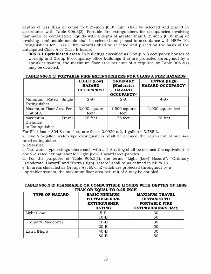
83
depths of less than or equal to 0.25-inch (6.35 mm) shall be selected and placed in accordance with Table 906.3(2). Portable fire extinguishers for occupancies involving flammable or combustible liquids with a depth of greater than 0.25-inch (6.35 mm) or involving combustible metals shall be selected and placed in accordance with NFPA 10. Extinguishers for Class C fire hazards shall be selected and placed on the basis of the anticipated Class A or Class B hazard.
906.3.1 Sprinklered areas. In buildings classified as Group A-3 occupancy houses of worship and Group B occupancy office buildings that are protected throughout by a sprinkler system, the maximum floor area per unit of A required by Table 906.3(1) may be doubled.
TABLE 906.3(1) PORTABLE FIRE EXTINGUISHERS FOR CLASS A FIRE HAZARDS LIGHT (Low)
HAZARD OCCUPANCYd
ORDINARY (Moderate) HAZARD
OCCUPANCYd
EXTRA (High) HAZARD OCCUPANCYd
Minimum Rated Single Extinguisher
2-Ac 2-A 4-Aa
Maximum Floor Area Per Unit of A
3,000 square feete
1,500 square feet
1,000 square feet
Maximum Travel Distance to Extinguisher
75 feet 75 feet 75 feet
For SI: 1 foot = 304.8 mm, 1 square foot = 0.0929 m2, 1 gallon = 3.785 L. a. Two 2.5-gallon water-type extinguishers shall be deemed the equivalent of one 4-A rated extinguisher. b. Reserved c. Two water-type extinguishers each with a 1-A rating shall be deemed the equivalent of one 2-A rated extinguisher for Light (Low) Hazard Occupancies. d. For the purposes of Table 906.3(1), the terms “Light (Low) Hazard”, “Ordinary
(Moderate) Hazard” and “Extra (High) Hazard” shall be as defined in NFPA 10. e. In areas classified as Groups A3, B, or E which are protected throughout by a
sprinkler system, the maximum floor area per unit of A may be doubled. TABLE 906.3(2) FLAMMABLE OR COMBUSTIBLE LIQUIDS WITH DEPTHS OF LESS
THAN OR EQUAL TO 0.25-INCH TYPE OF HAZARD BASIC MINIMUM
PORTABLE FIRE EXTINGUISHER
RATING
MAXIMUM TRAVEL DISTANCE TO
PORTABLE FIRE EXTINGUISHERS (feet)
Light (Low) 5-B 10-B
30 50
Ordinary (Moderate) 10-B 20-B
30 50
Extra (High) 40-B 80-B
30 50

84
906.4 Cooking grease fires. Portable fire extinguishers provided for the protection of cooking grease fires shall be of an approved type compatible with the fire extinguishing system agent and in accordance with Section 904.11.5. 906.5 Conspicuous location. Portable fire extinguishers shall be located in conspicuous locations where they will be readily accessible and immediately available for use. These locations shall be along normal paths of travel, unless the commissioner determines that the hazard posed indicates the need for placement away from normal paths of travel.
Exceptions: 1. Portable fire extinguishers subject to theft, malicious use or damage may be
located in locations approved by the commissioner. 2. In rooming houses and single room occupancies, as defined in the New York
State Multiple Dwelling Law, with over 15 sleeping rooms, a 2-A rated portable fire extinguisher may be kept in the apartment of the manager or the building superintendent.
906.6 Unobstructed and unobscured. Portable fire extinguishers shall not be obstructed or obscured from view. In rooms or areas in which visual obstruction cannot be completely avoided, signs or other markings shall be provided to indicate the locations of portable fire extinguishers. 906.7 Hangers and brackets. Hand-held portable fire extinguishers, not housed in cabinets, shall be installed on the hangers or brackets supplied. Hangers or brackets shall be securely anchored to the mounting surface in accordance with the manufacturer’s installation instructions. 906.8 Cabinets. Cabinets used to house portable fire extinguishers shall be readily identifiable and shall not be locked.
Exceptions: 1. Portable fire extinguishers subject to theft, malicious use or damage, if provided
with an approved means of ready access. 2. Portable fire extinguishers in Group I-3 occupancies and in mental health areas
in Group I-2 occupancies may be locked or located in staff locations, provided the staff of the institution has ready access to the cabinet or other storage location.
906.9 Height above floor. Portable fire extinguishers having a gross weight not exceeding 40 pounds (18 kg) shall be installed so that their tops are not more than 5 feet (1524 mm) above the floor. Hand-held portable fire extinguishers having a gross weight exceeding 40 pounds (18 kg) shall be installed so that their tops are not more than 3.5 feet (1067 mm) above the floor. The clearance between the floor and the bottom of installed hand-held extinguishers shall not be less than 4 inches (102 mm). 906.10 Wheeled units. Wheeled portable fire extinguishers shall be conspicuously located in a designated location.
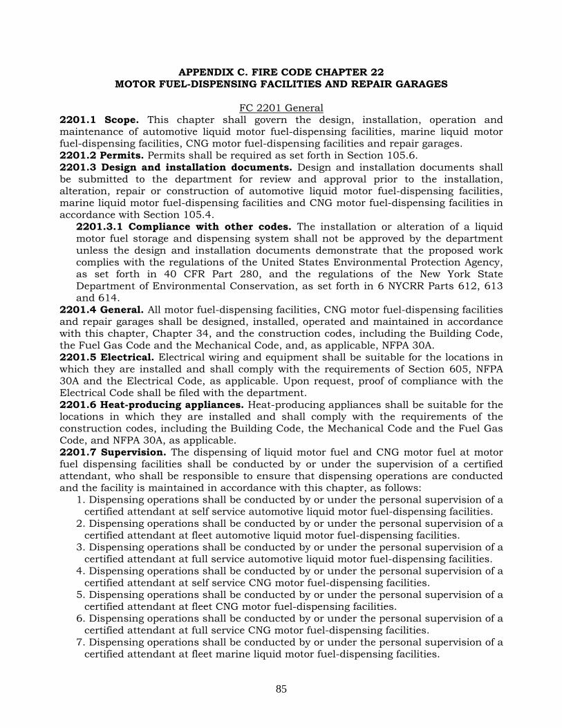
85
APPENDIX C. FIRE CODE CHAPTER 22 MOTOR FUEL-DISPENSING FACILITIES AND REPAIR GARAGES
FC 2201 General
2201.1 Scope. This chapter shall govern the design, installation, operation and maintenance of automotive liquid motor fuel-dispensing facilities, marine liquid motor fuel-dispensing facilities, CNG motor fuel-dispensing facilities and repair garages. 2201.2 Permits. Permits shall be required as set forth in Section 105.6. 2201.3 Design and installation documents. Design and installation documents shall be submitted to the department for review and approval prior to the installation, alteration, repair or construction of automotive liquid motor fuel-dispensing facilities, marine liquid motor fuel-dispensing facilities and CNG motor fuel-dispensing facilities in accordance with Section 105.4.
2201.3.1 Compliance with other codes. The installation or alteration of a liquid motor fuel storage and dispensing system shall not be approved by the department unless the design and installation documents demonstrate that the proposed work complies with the regulations of the United States Environmental Protection Agency, as set forth in 40 CFR Part 280, and the regulations of the New York State Department of Environmental Conservation, as set forth in 6 NYCRR Parts 612, 613 and 614.
2201.4 General. All motor fuel-dispensing facilities, CNG motor fuel-dispensing facilities and repair garages shall be designed, installed, operated and maintained in accordance with this chapter, Chapter 34, and the construction codes, including the Building Code, the Fuel Gas Code and the Mechanical Code, and, as applicable, NFPA 30A. 2201.5 Electrical. Electrical wiring and equipment shall be suitable for the locations in which they are installed and shall comply with the requirements of Section 605, NFPA 30A and the Electrical Code, as applicable. Upon request, proof of compliance with the Electrical Code shall be filed with the department. 2201.6 Heat-producing appliances. Heat-producing appliances shall be suitable for the locations in which they are installed and shall comply with the requirements of the construction codes, including the Building Code, the Mechanical Code and the Fuel Gas Code, and NFPA 30A, as applicable. 2201.7 Supervision. The dispensing of liquid motor fuel and CNG motor fuel at motor fuel dispensing facilities shall be conducted by or under the supervision of a certified attendant, who shall be responsible to ensure that dispensing operations are conducted and the facility is maintained in accordance with this chapter, as follows:
1. Dispensing operations shall be conducted by or under the personal supervision of a certified attendant at self service automotive liquid motor fuel-dispensing facilities.
2. Dispensing operations shall be conducted by or under the personal supervision of a certified attendant at fleet automotive liquid motor fuel-dispensing facilities.
3. Dispensing operations shall be conducted by or under the personal supervision of a certified attendant at full service automotive liquid motor fuel-dispensing facilities.
4. Dispensing operations shall be conducted by or under the personal supervision of a certified attendant at self service CNG motor fuel-dispensing facilities.
5. Dispensing operations shall be conducted by or under the personal supervision of a certified attendant at fleet CNG motor fuel-dispensing facilities.
6. Dispensing operations shall be conducted by or under the personal supervision of a certified attendant at full service CNG motor fuel-dispensing facilities.
7. Dispensing operations shall be conducted by or under the personal supervision of a certified attendant at fleet marine liquid motor fuel-dispensing facilities.

86
8. Dispensing operations shall be conducted by or under the personal supervision of a certified attendant at full service marine liquid motor fuel-dispensing facilities.
2201.8 Certificate of license. Persons who install, alter, test or repair any automotive or marine liquid motor fuel storage and dispensing systems shall hold a certificate of license or shall be employed by and perform such duties under the general supervision of a person holding such certificate. 2201.9 Records of inspections and testing. Records of all inspections and testing required by this chapter shall be kept in a bound log book or other approved recordkeeping, maintained on the premises for a minimum of 4 years, and made available for inspection by any representative of the department.
FC 2202 Definitions
2202.1 Definitions. The following terms shall, for the purposes of this chapter and as used elsewhere in this code, have the meanings shown herein. AUTOMOTIVE LIQUID MOTOR FUEL-DISPENSING FACILITY. Any building, structure or premises upon which or wherein, liquid motor fuel is stored and dispensed from a liquid motor fuel storage and dispensing system into the fuel tanks of motor vehicles or motorcycles. CERTIFIED ATTENDANT. A person holding a certificate of fitness for the supervision of an automotive liquid motor fuel-dispensing facility, marine liquid motor fuel-dispensing facility or automotive CNG motor fuel-dispensing facility. CNG. Compressed natural gas. CNG MOTOR FUEL. CNG used as fuel in the operation of motor vehicles. CNG MOTOR FUEL SYSTEM. A system comprised of compressors, storage containers, dispensers, piping, valves and ancillary equipment, that compresses natural gas into CNG, and stores and/or dispenses CNG motor fuel. CNG MOTOR FUEL-DISPENSING FACILITY. Any building, structure or premises upon which, or wherein, CNG motor fuel is stored and/or dispensed from a CNG motor fuel system into the fuel tank of motor vehicles or watercraft. DISPENSING DEVICE, OVERHEAD TYPE. A dispensing device mounted above a dispensing area, typically within a canopy structure, and characterized by the use of an overhead hose reel. FLAMMABLE LIQUID MOTOR FUEL. Gasoline or other flammable liquids used as fuel in the operation of motor vehicles, motorcycles, watercraft and aircraft. FLEET MARINE LIQUID MOTOR FUEL-DISPENSING FACILITY. A marine liquid motor fuel-dispensing facility wherein liquid motor fuel is stored and/or dispensed into the fuel tank of watercraft owned or operated by or on behalf of the owner of the facility, and where such dispensing operations are conducted by persons employed by or otherwise working for the owner of the facility. FLEET CNG MOTOR FUEL-DISPENSING FACILITY. Any CNG motor fuel-dispensing facility wherein CNG motor fuel is stored and/or dispensed into the fuel tank of motor vehicles or watercraft owned or operated by or on behalf of the owner of the facility itself, and where dispensing operations are conducted by persons employed by or otherwise working for the owner of the facility. FLEET AUTOMOTIVE LIQUID MOTOR FUEL-DISPENSING FACILITY. An automotive liquid motor fuel-dispensing facility wherein liquid motor fuel is stored and/or dispensed into the fuel tank of motor vehicles or motorcycles owned or operated by or on behalf of the owner of the facility, and where dispensing operations are conducted by persons employed by or otherwise working for the owner of the facility.

87
FULL SERVICE AUTOMOTIVE LIQUID MOTOR FUEL-DISPENSING FACILITY. An automotive liquid motor fuel-dispensing facility wherein liquid motor fuel is dispensed into the fuel tank of motor vehicles or motorcycles by a certified attendant or, when under the personal supervision of a certified attendant, by persons employed by or otherwise working for the owner of the facility. FULL SERVICE CNG MOTOR FUEL-DISPENSING FACILITY. A CNG motor fuel-dispensing facility wherein CNG is dispensed into the fuel tank of motor vehicles or watercraft by a certified attendant or, when under the personal supervision of a certified attendant, by persons employed by or otherwise working for the owner of the facility. FULL SERVICE MARINE LIQUID MOTOR FUEL-DISPENSING FACILITY. A marine liquid motor fuel-dispensing facility wherein liquid motor fuel is dispensed into the fuel tank of watercraft by a certified attendant or, when under the personal supervision of a certified attendant, by persons employed by or otherwise working for the owner of the facility. LIQUEFIED NATURAL GAS (LNG). A fluid in the liquid state composed predominantly of methane and which may contain minor quantities of ethane, propane, nitrogen or other components normally found in natural gas. LIQUID MOTOR FUEL. Gasoline, diesel fuel or other flammable or combustible liquids used as fuel in the operation of motor vehicles, motorcycles, watercraft and aircraft. LIQUID MOTOR FUEL STORAGE AND DISPENSING SYSTEM. A liquid motor fuel storage tank and all motor fuel storage and dispensing equipment associated with such tank, including the tank, piping, valves, fill connection catchment basins, vent lines, pumps, dispensing devices and any other ancillary equipment. MARINE LIQUID MOTOR FUEL-DISPENSING FACILITY. Any building, structure or premises, whether on shore, piers, docks or wharves, upon which or wherein, liquid motor fuel is stored and/or dispensed from a liquid motor fuel storage and dispensing system into the fuel tanks of watercraft. MOTOR VEHICLE. A vehicle or other conveyance having more than 2 running wheels and using liquid motor fuel or flammable gas as fuel for generating motive power, except such vehicles as have a storage tank with a maximum capacity for less than 2 gallons (7.6 L) of liquid motor fuel or flammable gas that generates energy that is equivalent to the energy generated by 2 gallons (7.6 L) of gasoline. REPAIR GARAGE. A building, structure or portion thereof used for servicing or repairing motor vehicles or motorcycles. SELF-SERVICE AUTOMOTIVE LIQUID MOTOR FUEL-DISPENSING FACILITY. An automotive liquid motor fuel-dispensing facility where liquid motor fuel is dispensed from a liquid motor fuel storage and dispensing system into the fuel tank of motor vehicles or motorcycles by customers of the facility. SELF-SERVICE CNG MOTOR FUEL-DISPENSING FACILITY. A CNG motor fuel-dispensing facility wherein CNG motor fuel is stored and/or dispensed from a CNG motor fuel system into the fuel tank of motor vehicles by customers of the facility. TANK, PROTECTED ABOVEGROUND. An atmospheric aboveground tank listed in accordance with UL 2085 or equivalent standard that is provided with integral secondary containment, protection from physical damage, and an insulation system intended to reduce the heat transferred to the primary tank when the tank is exposed to a high intensity liquid pool fire.
FC 2203 Automotive liquid motor fuel-dispensing facility location of dispensing devices
2203.1 Location of dispensing devices. Dispensing devices at automotive liquid motor fuel-dispensing facilities shall be located as set forth in Sections 2203.1.1 and 2203.1.2.

88
2203.1.1 Outdoor dispensing devices. When installed outdoors, dispensing devices shall be located as follows:
1. Ten feet (3048 mm) or more from lot lines and building or structure openings. 2. Ten feet (3048 mm) or more from buildings or structures having combustible
exterior wall surfaces or buildings or structures having noncombustible exterior wall surfaces that are not part of a 1-hour fire-resistance-rated assembly or buildings or structures having combustible overhangs.
Exception: Canopies constructed in accordance with the construction codes, including the Building Code, providing weather protection for the motor fuel dispensers.
3. Such that all portions of the vehicle being fueled will be on the premises of the automotive liquid motor fuel-dispensing facility.
4. Such that the nozzle, when the hose is fully extended, will not reach within 5 feet (1524 mm) of building or structure openings.
5. Twenty feet (6096 mm) or more from fixed sources of ignition. 6. Twenty five feet (7620 mm) or more from the nearest subway grating, entrance
or exit. 2203.1.2 Indoor dispensing devices. When installed inside a building or structure, the dispensing area shall be located at street level, with no dispenser located more than 50 feet (15 240 mm) from an exit or entrance to the building or structure used by motor vehicles.
2203.2 Emergency disconnect switches. An approved, clearly identified and readily accessible emergency disconnect switch shall be provided at an approved location, to immediately shut down the transfer of fuel to the fuel dispensers in the event of a fuel spill or other emergency. An emergency disconnect switch for exterior fuel dispensers shall be located within 100 feet (30 480 mm) of, but not less than 20 feet (6096 mm) from, the fuel dispensers. For interior fuel-dispensing operations, the emergency disconnect switch shall be installed at an approved location. An approved sign shall be posted on or immediately adjacent to such devices and shall read: EMERGENCY FUEL SHUTOFF. Such emergency disconnect switches shall be of a type that is reset manually.
FC 2204 Automotive Liquid Motor Fuel-Dispensing Facility Dispensing Operations
2204.1 Supervision of dispensing. The dispensing of liquid motor fuel at automotive liquid motor fuel-dispensing facilities shall be conducted under the supervision of a certified attendant as set forth in Section 2201.7. 2204.2 Self-service automotive liquid motor fuel-dispensing facilities. Self-service automotive liquid motor fuel-dispensing facilities shall comply with the requirements of Sections 2204.2.1 through 2204.2.7. The certified attendant’s primary function shall be to supervise, observe and monitor the dispensing of fuel. The certified attendant shall prevent the dispensing of fuel into containers that do not comply with the requirements of Section 2204.4.1, control sources of ignition, take immediate action upon an accidental spill or release, be ready to use a portable fire extinguisher, and activate the fixed fire extinguishing system. Nothing in this section shall be construed to prohibit a certified attendant from engaging in other activities so long as such activities do not interfere with the certified attendant’s ability to supervise, observe and monitor the dispensing of fuel and other requirements of this chapter.
2204.2.1 Self-service dispensers. Approved self-service devices, equipment and systems such as, but not limited to, card- operated and remote-preset types, are allowed at automotive liquid motor fuel-dispensing facilities. The certified attendant

89
shall set the dispensing devices in the “off” position when not in use if such dispensing device can be activated without the certified attendant’s knowledge. 2204.2.2 Emergency controls. Approved emergency controls shall be provided in accordance with Section 2203.2. 2204.2.3 Operating instructions. Dispenser operating instructions shall be conspicuously posted in approved locations on every dispenser and shall indicate the location of the emergency controls required by Section 2204.2.2. 2204.2.4 Monitoring of dispensing. A control area shall be located on the premises of every self-service automotive liquid motor fuel-dispensing facility. The control area shall be an interior or exterior enclosure to which the public has no access. The certified attendant shall be present within the control area while dispensing operations are conducted. The control area shall be designed and located so that the certified attendant stationed therein shall have a full, unobstructed clear view of dispensing operations, except that mirrors and/or an approved closed-circuit television installation may be provided to afford the certified attendant a clear view of dispensing operations when the view from the control area is partially or temporarily obstructed. For purposes of this section, the “clear” view provided by a closed-circuit television installation shall mean that the image on the monitor shall be of such brightness and resolution as to allow ready identification of individuals and easy observation of activities at all times of day. Properly labeled manual switches that activate the fire extinguishing system and electrically disconnect the liquid motor fuel dispensing pumps shall be located adjacent to each other within the control area. A console that controls the self-service liquid motor fuel dispensers shall be provided within the control area and within 5 feet (1524 mm) of the manual switches. 2204.2.5 Communications. A two-way voice communication system shall be installed to provide contact between the control area and each dispensing island. A telephone not requiring a coin to operate, or other approved clearly identified means to notify the department, shall be provided at the facility in an approved location. 2204.2.6 Control area sign. A durable metal sign that reads as follows shall be posted in plain view within the control area:
Emergency Procedures: Shut off product pumps.
Direct vehicle occupants to exit vehicles and leave area immediately. Keep all persons away from the area.
Manually activate fire extinguishing system. Notify the Fire Department (Call 911).
Such sign shall also indicate the department telephone number, the nearest fire alarm box location, and the motor fuel-dispensing facility’s address, with cross-street reference. 2204.2.7 Lighting. Dispensing areas shall be well lighted whenever the facility is open for business.
2204.3 Fleet automotive liquid motor fuel-dispensing facilities. Fleet automotive liquid motor fuel-dispensing facilities shall comply with the requirements of Sections 2204.3.1 through 2204.3.7.
2204.3.1 General. The owner of fleet automotive liquid motor fuel-dispensing facilities shall provide, and be accountable for, daily site visits, regular equipment inspection, and maintenance.
2204.3.1.1 Supervision. The supervision of dispensing shall be in accordance with Section 2201.7.

90
2204.3.2 Reserved. 2204.3.3 Emergency controls. Approved emergency controls shall be provided in accordance with Section 2203.2. 2204.3.4 Operating instructions. Dispenser operating instructions shall be conspicuously posted in approved locations on every dispenser and shall indicate the location of the emergency controls required by Section 2204.3.3. 2204.3.5 Emergency procedures. An approved emergency procedures sign, in addition to the sign required by Section 2206.12, shall be posted in a conspicuous location and shall read:
IN CASE OF FIRE, SPILL OR RELEASE 1. USE EMERGENCY PUMP SHUTOFF
2. ACTIVATE THE FIRE EXTINGUISHING SYSTEM PROTECTING THE FLAMMABLE LIQUID MOTOR FUEL DISPENSING AREA.
(where applicable) FIRE SUPPRESSION EMERGENCY CONTROL LOCATED (indicate location)
3. NOTIFY THE FIRE DEPARTMENT (CALL 911) FACILITY ADDRESS (indicate address, with cross street reference).
2204.3.6 Communications. A telephone not requiring a coin to operate or other approved, clearly identified means to notify the department shall be provided at the facility in an approved location. 2204.3.7 Quantity limits. Dispensing equipment used at fleet automotive liquid motor fuel-dispensing facilities shall comply with one of the following:
1. Dispensing devices shall be programmed or set to limit uninterrupted liquid motor fuel delivery to not more than 25 gallons (95 L) and require a manual action to resume delivery.
2. For other than flammable liquid motor fuel, the amount of liquid motor fuel being dispensed shall be limited in quantity by a preprogrammed card as approved.
2204.4 Dispensing into portable containers. The dispensing of liquid motor fuel into portable containers shall comply with the requirements of Sections 2204.4.1 through 2204.4.4.
2204.4.1 Approved containers required. Liquid motor fuel shall not be dispensed into a portable container unless such container is of approved material and construction, and has a tight closure with screwed or spring-loaded cover so designed that the contents can be dispensed without spilling. Liquids shall not be dispensed into portable tanks or cargo tanks.
2204.4.1.1 Container capacity. Liquid motor fuel shall be dispensed into approved containers with an individual capacity not greater than 2½ gallons (9.5 L).
2204.4.2 Nozzle operation. A hose nozzle valve used for dispensing liquid motor fuel into a portable container shall be in compliance with the requirements of Section 2206.7.6 and be manually held open during the dispensing operation. 2204.4.3 Location of containers being filled. Portable containers shall not be filled while located inside the trunk, passenger compartment or truck bed of a vehicle or upon a watercraft. 2204.4.4 Certified attendant. Only a certified attendant shall dispense liquid motor fuel into portable containers.
2204.5 Dispensing from portable containers. No motor vehicle, motorcycle or watercraft shall be fueled from a portable container while inside a building or structure.

91
2204.6 Full service automotive liquid motor fuel-dispensing facilities. Full service automotive liquid motor fuel-dispensing facilities shall comply with the requirements of Sections 2204.6.1 through 2204.6.5.
2204.6.1 Supervision of dispensing. Dispensing of liquid motor fuel shall be in accordance with Section 2201.7. 2204.6.2 Emergency controls. Approved emergency controls shall be provided in accordance with Section 2204.3.3. 2204.6.3 Operating instructions. Dispenser operating instructions shall be conspicuously posted in approved locations on every dispenser and shall indicate the location of the emergency controls required by Section 2204.6.2. 2204.6.4 Emergency procedures. An approved emergency procedures sign, in addition to the sign required by Section 2206.12, shall be provided and posted in accordance with Section 2204.3.5. 2204.6.5 Communications. A telephone not requiring a coin to operate or other approved, clearly identified means to notify the department shall be provided at the facility in an approved location.
2204.7 Sources of ignition. It shall be unlawful to smoke or use or maintain an open flame in areas where fuel is dispensed. The engines of vehicles being fueled shall be shut off during fueling. Electrical equipment shall be installed, operated and maintained in accordance with the Electrical Code. 2204.8 Liquid motor fuel dispensing on piers, docks or wharves. Flammable liquid motor fuel shall not be dispensed into the fuel tanks of motor vehicles imported by ship to this country while on any pier, dock or wharf.
FC 2205 Automotive Liquid Motor Fuel-Dispensing Facility Operational and Maintenance
Requirements 2205.1 Tank filling operations for liquid motor fuel. Delivery operations to tanks for liquid motor fuel shall comply with the requirements of Sections 2205.1.1 through 2205.1.3 and the applicable requirements of Chapter 34.
2205.1.1 Delivery vehicle location. Where liquid delivery to aboveground storage tanks is accomplished by positive-pressure operation, cargo tanks shall be positioned a minimum of 15 feet (4572 mm) from tanks receiving liquid motor fuel. During delivery, a cargo tank shall not obstruct a public street, block motorists' view of roadways or impede the movement of vehicles or pedestrians. 2205.1.2 Tank capacity calculation. The driver, operator or attendant of a cargo tank shall, before making delivery to a tank, determine the unfilled, available capacity of such tank by an approved tank level gauging device or method. A measuring stick shall not be used to measure the contents of the tank through the fill connection line, except where there is a direct fill connection. 2205.1.3 Tank connections. Delivery of liquid motor fuel shall be made by means of approved liquid- and vapor-tight connections between the delivery hose and tank fill pipe. Where tanks are equipped with any type of vapor recovery system, all connections required for the safe and proper functioning of the particular vapor recovery process shall be made. Such connections shall be made liquid and vapor tight and remain connected throughout the unloading process. Vapors shall not be discharged at grade level during delivery.
2205.2 Equipment maintenance. Automotive liquid motor fuel-dispensing facility equipment shall be maintained in good working order at all times in accordance with Sections 2205.2.1 through 2205.2.3.

92
2205.2.1 Dispensing devices. Where maintenance to dispensing devices becomes necessary and such maintenance could allow the accidental release or ignition of liquid, the following precautions shall be taken:
1. Only persons with a certificate of license and knowledgeable in performing the required maintenance shall perform the work.
2. Electrical power to the dispensing device and pump serving the dispenser shall be shut off at the main electrical disconnect panel before maintenance begins.
3. The emergency shutoff valve at the dispenser, where installed, shall be closed before maintenance begins.
4. Vehicle traffic and unauthorized persons shall be prevented from coming within 12 feet (3658 mm) of the dispensing device before and during maintenance.
2205.2.2 Emergency shutoff valves. Automatic-closing emergency shutoff valves required by Section 2206.7.4 shall be checked not less than once per year by manually tripping the hold-open linkage. 2205.2.3 Leak detection system. The leak detection system required by Section 2206.7.7 shall be inspected monthly for proper operation and tested at least annually in accordance with the manufacturer’s specifications to ensure proper installation and operation.
2205.3 Reserved. 2205.4 Reserved. 2205.5 Fire extinguishers. Approved portable fire extinguishers complying with the requirements of Section 906 with a minimum rating of 40-B:C shall be provided and located such that an extinguisher is not less than 20 feet (6096 mm) but not more than 75 feet (22 860 mm) from pumps, dispensers or storage tank fill-pipe openings. 2205.6 Reserved. 2205.7 Control of brush and debris. Brush, grass, vines or other vegetation and combustible waste shall be kept not less than 10 feet (3048 mm) from the tank and dispensing location.
FC 2206 Automotive Liquid Motor Fuel-Dispensing Facilities Design and Installation
Requirements 2206.1 General. Storage of liquid motor fuel shall be in accordance with Chapter 34 except as otherwise specified in this chapter. 2206.2 Method of storage. Approved methods of storage for liquid motor fuel at automotive liquid motor fuel-dispensing facilities shall be in accordance with Sections 2206.2.1 through 2206.2.4.
2206.2.1 Underground tanks. The installation of underground tanks for the storage of liquid motor fuel shall comply with the requirements of Chapter 34 except as otherwise specified in this chapter.
2206.2.1.1 Inventory control for underground tanks. Accurate daily inventory records shall be maintained and reconciled for underground liquid motor fuel storage tanks for indication of possible leakage from tanks and piping. Inventory reconciliation shall be in accordance with the regulations of the New York State Department of Environmental Conservation as set forth in 6 NYCRR Part 613. The records shall be kept at the premises and be made available for inspection by any representative of the department. Records shall include daily reconciliation between sales, use, receipts and inventory on hand. Where there is more than one system consisting of tanks serving separate pumps or dispensers for a product, the reconciliation shall be maintained separately for each tank system. A

93
consistent or accidental loss of product shall be immediately reported to the commissioner. 2206.2.1.2 Listing and approval. Underground liquid motor fuel storage tanks shall be listed and approved. 2206.2.1.3 Tank design and construction. Underground liquid motor fuel storage tanks shall be designed and constructed in accordance with the following:
1. Tanks shall be completely double-walled and constructed of steel, fiberglass-reinforced plastic or a combination of both materials. The secondary tank shall be capable of containing any leakage from the primary tank.
2. Tanks shall be designed and constructed to withstand 1.5 times the maximum operating loads and stresses, regardless of the amount of liquid motor fuel contained in the tank. Such capabilities shall be established by buoyancy calculations and load and stress analyses.
3. Tanks shall be designed and constructed to withstand a pressure of 15 pounds per square inch gauge (psig)(103.4 kPa) or 1½ times the maximum anticipated static head pressure, whichever is greater, for the primary tank and 5 pounds per square inch gauge (psig)(34.5 kPa) for the secondary tank.
4. The capacity of each individual tank shall not exceed 12,000 gallons (45 420 L) of liquid motor fuel.
2206.2.2 Prohibited aboveground storage. The storage of motor fuel in aboveground tanks shall be prohibited as set forth in Sections 2206.2.2.1, 2206.2.2.2 and 2206.2.2.3.
2206.2.2.1 Storage of flammable liquid motor fuel. It shall be unlawful to store flammable liquid motor fuel in aboveground tanks. 2206.2.2.2 Storage of combustible liquid motor fuel. It shall be unlawful to store combustible liquid motor fuel in aboveground tanks, except at a fleet liquid motor fuel-dispensing facility complying with the requirements of this chapter. 2206.2.2.3 Storage inside buildings. It shall be unlawful to store liquid motor fuel in aboveground tanks within any building or structure.
2206.2.3 Aboveground tanks located outdoors, at grade. Outdoor storage of combustible liquid motor fuel in aboveground tanks at a fleet liquid motor fuel-dispensing facility shall comply with the requirements set forth in Sections 2206.2.3.1 through 2206.2.3.5.
2206.2.3.1 Tank design and construction. Only protected aboveground tanks shall be used. 2206.2.3.2 Tank capacity. The capacity of each tank shall not exceed 4,000 gallons (15 140 L). Not more than a total of 4,000 gallons (15 140 L) of liquid motor fuel shall be stored aboveground at any facility. The total storage capacity at a facility in both aboveground and underground tanks shall not exceed 40,000 gallons (15 140 L) of liquid motor fuel. Each tank shall have a separate fill line and a separate vent line that are separate from the fill and vent lines of other tanks.
Exception: When approved, individual tanks may exceed 4,000 gallons (151 400 L) but shall not exceed 12,000 gallons (45 420 L).
2206.2.3.3 Tank base support. Tanks shall be placed on an approved base slab. The surface of such base slab shall be a minimum of 6 inches (152 mm) above the level of the surrounding area to permit visual inspection. Tanks shall be adequately supported and anchored to the base slab to withstand uplifting by surface water and flooding. 2206.2.3.4 Tank connections. Tank connections shall be designed and located so as to:

94
1. Minimize the maneuvering necessary to position a cargo tank to make the delivery.
2. Minimize obstructing a public right of way or motorists’ view of roadways, or impeding the movement of motor vehicles or pedestrians, during deliveries.
3. Provide connections by means of approved liquid and vapor-tight connections.
2206.2.3.5 Liquid level-indicating devices. Tanks shall be provided with an approved liquid level-indicating device. The liquid level-indicating device shall be accessible to the delivery operator. Liquid level indicating devices shall be designed and constructed to be vapor-and-liquid tight.
2206.2.4 Location requirements for aboveground tanks at fleet automotive liquid motor fuel-dispensing facilities. Tanks shall be located in accordance with Table 2206.2.3 and as follows:
1. A minimum of 25 feet (7620 mm) from a subway grating, entrance or exit. 2. At a location that will not obstruct or interfere with any means of egress or
department access. 3. Tanks shall not be installed under electrical transmission lines, bridges, or
public highways. TABLE 2206.2.3 MINIMUM SEPARATION REQUIREMENTS FOR ABOVEGROUND
TANKS AT FLEET MOTOR FUEL-DISPENSING FACILITIES CLASS OF
LIQUID AND TANK
TYPE
INDIVIDUAL TANK
CAPACITY (gallons)
MINIMUM DISTANCE
FROM NEAREST BUILDIN G(feet)
MINIMUM DISTANCE
FROM LOT LINE
(feet)
MINIMUM DISTANCE
FROM PUBLIC
STREET OR PRIVATE
ROAD (feet)
MINIMUM DISTANCE BETWEEN
TANKS (feet)
Liquid motor fuel
tanks
4000 > 4000
15 25
15 25
5 15
3 3
For SI: 1 foot = 304.8 mm, 1 gallon = 3.785 L. 2206.3 Security. Aboveground tanks for the storage of liquid motor fuel shall be safeguarded in an approved manner from public access or unauthorized entry. 2206.4 Physical protection. Posts complying with the requirements of Section 312 or other approved means shall be provided to protect aboveground tanks against impact by a motor vehicle unless the tank is listed as a protected aboveground tank with vehicle impact protection. 2206.5 Secondary containment. Aboveground tanks shall be provided with diking in accordance with Chapter 34. Diking is not required for listed secondary containment tanks. The secondary containment systems shall be monitored either visually or automatically. Enclosed secondary containment systems shall be provided with emergency venting in accordance with Section 2206.6.2.5. 2206.6 Piping, valves, fittings and ancillary equipment for use with liquid motor fuel. The design, fabrication, assembly, testing and inspection of piping, valves, fittings and ancillary equipment for use with liquid motor fuel shall be in accordance with Chapter 34 except as otherwise specified in Sections 2206.6.1 through 2206.6.3, 2206.9 and 2206.10.

95
2206.6.1 Protection from damage. Piping shall be located such that it is protected from physical damage and designed to accommodate settlement, vibration, expansion or contraction. 2206.6.2 Piping, valves, fittings and ancillary equipment for aboveground tanks. Piping, valves, fittings and ancillary equipment for aboveground tanks shall comply with the requirements of Sections 2206.6.2.1 through 2206.6.2.11.
2206.6.2.1 Tank openings. Tank openings for aboveground tanks shall be through the top only. There shall be no openings except those necessary to inspect, fill, empty and vent the tank. 2206.6.2.2 Fill-pipe connections. The fill-pipe for aboveground tanks shall be provided with a means for making a direct connection to the cargo tank’s fuel-delivery hose so that liquid motor fuel is not exposed to the open air during the filling operation. Operator safety equipment for the filling operation shall be provided in accordance with OSHA regulations. Where any portion of the fill-pipe exterior to the tank extends below the level of the top of the tank, a check valve, a dry break coupling and a quick closing valve shall be installed at the fill connection. Tank fill connections from a remote location are prohibited. 2206.6.2.3 Overfill protection. Overfill protection shall be provided for aboveground storage tanks. Overfill prevention devices shall be designed to withstand the pressure generated by the cargo tank discharge pump and shall automatically shut off the flow into the tank when the tank is not more than 95 percent full. 2206.6.2.4 Siphon prevention. An approved antisiphon method shall be provided in the piping system to prevent flow of liquid motor fuel by siphon action. 2206.6.2.5 Emergency relief venting. Aboveground storage tanks, tank compartments and enclosed secondary containment spaces shall be provided with emergency relief venting in accordance with Chapter 34. 2206.6.2.6 Spill containers. Aboveground tank spill containers having a capacity of not less than 5 gallons (19 L) shall be provided for each fill connection. Spill containers shall be noncombustible and shall be fixed to the tank and equipped with a manual drain valve that drains into the primary tank. 2206.6.2.7 Piping material construction. Piping shall be of a minimum Schedule 40 galvanized steel construction. 2206.6.2.8 Compatibility. Piping, fittings, components and joint compounds shall be mutually compatible, and compatible with diesel fuel and other commonly-used combustible liquid motor fuels, including the additives commonly used in such combustible motor fuels. Joint compounds shall be listed and approved. 2206.6.2.9 Pressure relief devices. Where liquid motor fuel may become trapped between shutoff valves and/or check valves, affected piping sections shall be provided with pressure-relief devices that will discharge the pressure generated by thermal expansion back into the tank. 2206.6.2.10 Vent piping. Each tank shall be provided with a separate unobstructed vent line, without any trap or device that causes excessive back pressure, and shall be maintained unobstructed at all times. 2206.6.2.11 Vent termination. Vent outlets shall discharge outdoors and upward. The discharge point shall be no less than 15 feet (4572 mm) above the adjacent ground level and no less than 15 feet (4572 mm) from the nearest building opening.

96
2206.6.3 Piping, valves, fittings and ancillary equipment for underground tanks. Piping, valves, fittings and ancillary equipment for underground tanks shall comply with the requirements of Chapter 34 and NFPA 30A, except as otherwise provided in Sections 2206.6.3.1, 2206.6.3.2 and 2206.10.
2206.6.3.1 Piping design and construction. Piping, including vent piping, shall be of a minimum Schedule 40 steel construction. Approved nonmetallic piping, such as fiberglass-reinforced plastic or other equivalent corrosion-resistant material, may be installed underground. 2206.6.3.2 Underground tank piping. Piping shall be installed underground, except for the vertical riser of the vent. 2206.6.3.3 Compatibility. Piping, fittings, components and joint compounds shall be mutually compatible, and compatible with gasoline, diesel fuel, methanol and other commonly-used liquid motor fuels, including the additives commonly used in such liquid motor fuels. Joint compounds shall be listed and approved.
2206.7 Fuel-dispensing systems for liquid motor fuel. The design, and installation of liquid motor fuel-dispensing systems shall be in accordance with this section.
2206.7.1 Listed equipment. Electrical equipment, dispensers, hose, nozzles and submersible or subsurface pumps used in fuel-dispensing systems shall be listed and approved. 2206.7.2 Fixed pumps required. Liquid motor fuel shall be transferred only from the top of the tank by means of fixed pumps designed and equipped to allow control of the flow and prevent leakage or accidental discharge.
2206.7.2.1 Aboveground tank dispenser. Only one vehicle may be fueled at a time. Fuel dispensing from a location remote from the tank may be permitted when approved by the commissioner. 2206.7.2.2 Pump sumps. Pump sumps shall be compatible with the liquid motor fuel, liquid-tight, and accessible for inspection. Prefabricated pump sumps shall be approved.
2206.7.3 Mounting of dispensers. Dispensing devices, except those installed on top of a protected aboveground tank that qualifies as vehicle-impact resistant, shall be protected against physical damage by mounting on a concrete island 6 inches (152 mm) or more in height, or shall otherwise be suitably protected in accordance with Section 312. Dispensing devices shall be installed and securely fastened to their mounting surface in accordance with the dispenser manufacturer’s instructions. Dispensing devices installed indoors shall be located in an approved position not in a direct line with vehicular traffic.
2206.7.3.1 Protection of floor openings in indoor facilities. Openings in floors beneath automotive liquid motor fuel-dispensing facilities located inside buildings or structures shall be sealed. 2206.7.3.2 Dispenser pans. If a dispenser pan is installed beneath a dispenser, it shall be approved, compatible with the liquid motor fuel, liquid-tight, accessible for inspection, no larger than necessary, and installed solely for the purpose of collecting any liquid motor fuel leaking from the dispenser. The dispenser pan shall not be used to collect liquid motor fuel discharged from defective piping. The dispenser pan shall be backfilled up to not less than 6 inches (152 mm) above any nonmetallic piping and shall not interfere with the operation of any safety device.
2206.7.4 Dispenser emergency valve. An approved emergency shutoff valve designed to close automatically in the event of a fire or impact shall be properly installed in the liquid supply line at the base of each dispenser supplied by a remote pump. The valve shall be installed so that the shear groove is flush with or within 0.5

97
inch (12.7 mm) of the top of the concrete dispenser island and there is clearance provided for maintenance purposes around the valve body and operating parts. The valve shall be installed at the liquid supply line inlet of each overhead-type dispenser. Where installed, a vapor return line located inside the dispenser housing shall have a shear section or approved flexible connector for the liquid supply line emergency shutoff valve to function. Emergency shutoff valves shall be installed and maintained in accordance with the manufacturer’s instructions, tested at the time of initial installation and tested at least yearly thereafter in accordance with Section 2205.2.2. 2206.7.5 Dispenser hose. Dispenser hoses shall be a maximum of 18 feet (5486 mm) in length unless otherwise approved. Dispenser hoses shall be listed and approved. When not in use, hoses shall be reeled, racked or otherwise protected from damage. The length of the dispensing hose shall be such that at least 1 inch (25.4 mm) clearance between the hose and the ground is maintained when the nozzle is rested on its bracket. Dispensing hoses installed at aviation facilities, marine liquid motor fuel-dispensing facilities, and fleet vehicle liquid motor fuel-dispensing facilities shall be of an approved length.
2206.7.5.1 Breakaway devices. Dispenser hoses shall be equipped with a listed emergency breakaway device designed to retain liquid on both sides of a breakaway point. Such devices shall be installed and maintained in accordance with the manufacturer’s instructions. Where hoses are attached to hose-retrieving mechanisms, the emergency breakaway device shall be located between the hose nozzle and the point of attachment of the hose-retrieval mechanism to the hose.
2206.7.6 Fuel delivery nozzles. A listed automatic-closing-type hose nozzle valve without a latch-open device shall be provided for dispensers used for dispensing liquid motor fuel, except that a nozzle valve with a latch-open device may be installed and used at the following automotive liquid motor fuel-dispensing facilities:
1. Full service automotive liquid motor fuel-dispensing facilities. 2. Fleet automotive liquid motor fuel-dispensing facilities. 3. Dispensing of diesel fuel at self-service automotive liquid motor fuel-dispensing
facilities. 2206.7.6.1 Special requirements for nozzles. Where dispensing of liquid motor fuel is performed, a listed automatic-closing-type hose nozzle valve shall be used that incorporates all of the following features:
1. The hose nozzle valve shall be equipped with an integral latch-open device, when the use of such a device is authorized by this section.
2. When the flow of product is normally controlled by devices or equipment other than the hose nozzle valve, the hose nozzle valve shall not be capable of being opened unless the delivery hose is pressurized. If pressure to the hose is lost, the nozzle shall close automatically. Exception: Vapor recovery nozzles incorporating insertion interlock devices designed to achieve shutoff on disconnect from the vehicle fill pipe.
3. The hose nozzle shall be designed such that the nozzle is retained in the fill pipe during the filling operation.
4. The system shall include listed equipment with a feature that causes or requires the closing of the hose nozzle valve before the product flow can be resumed or before the hose nozzle valve can be replaced in its normal position in the dispenser.
2206.7.6.2 Control device. A control device shall be provided that will allow a liquid motor fuel pump to operate only when the dispensing nozzle is removed from its bracket on the dispenser and the switch on the dispenser is manually

98
activated. The flow of liquid motor fuel shall automatically stop when the switch is deactivated or the nozzle returned to its bracket.
2206.7.7 Leak detection. Underground liquid motor fuel storage and dispensing systems shall be provided with a leak detection system in accordance with the following:
1. The leak detection system shall provide continuous monitoring of the tank's interstitial space.
2. The leak detection system shall provide continuous monitoring of liquid motor fuel pump sumps. Activation of the leak detection system shall cause shutdown of the liquid motor fuel pumps.
3. The leak detection system shall provide continuous monitoring of dispenser pans whenever such pans are provided. Activation of the leak detection system shall cause shutdown of the affected dispenser or liquid motor fuel pump supplying such dispenser.
4. Primary discharge piping shall be provided with an automatic line leak detector. Activation of such leak detector shall cause shutdown of the liquid motor fuel pump or significantly restrict the product flow.
5. The leak detection system shall have an alarm panel in a supervised location on the premises; trigger both an audible and visible local alarm; be capable of producing hardcopy printouts of all tests and/or leak notification reports; operate on low voltage; and be intrinsically safe for a liquid motor fuel environment.
6. Leak detection systems shall be listed and approved. 2206.7.8 Gravity and pressure dispensing. Liquid motor fuel shall not be dispensed by gravity from tanks, drums, barrels or similar containers. Liquid motor fuel shall not be dispensed by a device operating through pressure within a storage tank, drum or container. 2206.7.9 Vapor-recovery and vapor-processing systems. Vapor-recovery and vapor-processing systems shall be in accordance with Section 2206.7.9, the requirements of New York State Department of Environmental Conservation and be approved.
2206.7.9.1 Vapor-balance systems. Vapor-balance systems shall comply with the requirements of Sections 2206.7.9.1.1 through 2206.7.9.1.5.
2206.7.9.1.1 Dispensing devices. Dispensing devices incorporating provisions for vapor recovery shall be listed and labeled. When existing listed or labeled dispensing devices are modified for vapor recovery, such modifications shall be listed by report by a nationally recognized testing laboratory. The listing by report shall contain a description of the component parts used in the modification and the recommended method of installation on specific dispensers. Such report shall be made available for inspection by any department representative. Means shall be provided to shut down fuel dispensing in the event the vapor return line becomes blocked. 2206.7.9.1.2 Vapor-return line closeoff. An approved method shall be provided to close off the vapor return line from dispensers when the product is not being dispensed. 2206.7.9.1.3 Piping. Piping in vapor-balance systems shall be in accordance with Sections 3403.6 and 3404.2. Nonmetallic piping shall be installed in accordance with the manufacturer’s installation instructions. Vapor return piping shall be installed in a manner that drains back to the tank, without sags or traps in which liquid can become trapped. If necessary, because of

99
grade, condensate tanks are allowed in vapor return piping. Condensate tanks shall be designed and installed so that they can be drained without opening. 2206.7.9.1.4 Flexible joints and shear joints. Flexible joints shall be installed in accordance with Section 3403.6.9. An approved shear joint shall be rigidly mounted and connected by a union in the vapor return piping at the base of each dispensing device. The shear joint shall be mounted flush with the top of the surface on which the dispenser is mounted. 2206.7.9.1.5 Testing. Vapor return lines and vent piping shall be tested in accordance with Section 2206.9.
2206.7.9.2 Vapor-processing systems. Vapor-processing systems shall comply with the requirements of Sections 2206.7.9.2.1 through 2206.7.9.2.4.
2206.7.9.2.1 Equipment. Equipment in vapor-processing systems, including hose nozzle valves, vapor pumps, flame arresters, fire checks or systems for prevention of flame propagation, controls and vapor-processing equipment, shall be individually listed for the intended use in a specified manner. Vapor-processing systems that introduce air into the underground piping or storage tanks shall be provided with equipment for prevention of flame propagation that has been tested and listed as suitable for the intended use. 2206.7.9.2.2 Location. Vapor-processing equipment shall be located at or above grade. Sources of ignition shall be located not less than 50 feet (15 240 mm) from fuel-transfer areas and not less than 18 inches (457 mm) above tank fill openings and tops of dispenser islands. Vapor-processing units shall be located not less than 10 feet (3048 mm) from the nearest building or structure or lot line.
Exception: Where the required distances to buildings or structures, lot lines or fuel-transfer areas cannot be obtained, means shall be provided to protect equipment against fire exposure. Acceptable means shall include:
1. Approved protective enclosures, which extend at least 18 inches (457 mm) above the equipment, constructed of fire-resistant or noncombustible materials; and
2. Fire protection using an approved water-spray system. 2206.7.9.2.2.1 Location and safeguards. Vapor-processing equipment shall be located a minimum of 20 feet (6096 mm) from dispensing devices. Processing equipment shall be protected against physical damage by guardrails, curbs, protective enclosures or fencing. Where approved protective enclosures are used, approved means shall be provided to ventilate the volume within the enclosure to prevent pocketing of flammable vapors. Where a downslope exists toward the location of the vapor-processing unit from a fuel-transfer area, the commissioner may require additional separation by distance and height.
2206.7.9.2.3 Installation. Vapor-processing units shall be securely mounted on concrete, masonry or structural steel supports on concrete or other noncombustible foundations. Vapor-recovery and vapor-processing equipment is allowed to be installed on roofs when approved. 2206.7.9.2.4 Piping. Piping in a mechanical-assist system shall be in accordance with Section 3403.6.
2206.8 Fire extinguishing system for dispensing area. Where flammable liquid motor fuel is dispensed at an automotive liquid motor fuel-dispensing facility, the dispensing area shall be provided with a dry chemical fire extinguishing system designed and installed in accordance with Section 904.6, and the following requirements:

100
1. The fire extinguishing system shall be designed to provide overhead protection of the dispenser area encompassed by a circle formed by the fully extended hose and nozzle on each fuel dispenser and both ends of the dispenser island.
2. The extinguishing agent containers shall be equipped with indicators to show whether the system is fully charged. Indicators shall be positioned to be easily read from grade.
3. The installation, alteration, testing and repair of the fire extinguishing system, including any maintenance or modification of the system, shall be performed by a person possessing a master fire suppression piping contractor license issued by the New York City Department of Buildings and trained and knowledgeable in the installation, operation and maintenance of the specific fire extinguishing system.
4. Dispensers shall not be operated when the fire extinguishing system has discharged or is inoperative, except as authorized in writing by the department. The motor fuel-dispensing facility certified attendant shall immediately notify the department of system discharge or inoperability.
5. Fire extinguishing systems shall be inspected and tested in accordance with Section 2206.9.
6. Fire extinguishing systems at fleet vehicle automotive liquid motor fuel-dispensing facilities shall be monitored by an approved central station company.
2206.9 Inspection and testing. Inspection and testing required by Sections 2206.9.1 through 2206.9.7 shall be conducted at the owner’s risk by his or her representative before a representative of the department.
2206.9.1 Initial tank test. Underground and aboveground tanks shall be tested hydrostatically at 15 pounds per square inch (psig)(103.4 kPa), or 1½ times the maximum anticipated static head pressure, whichever is greater, for the inner tank, and pneumatically or hydrostatically at 5 pounds per square inch (psig)(34.5 kPa) for the annular space (secondary containment tank). When a pneumatic test is allowed, an inert gas shall be used; however, air may be used if the tank or piping system does not contain any liquid motor fuel or combustible vapor. Test pressure shall be maintained for a sufficient time to complete visual inspection, but not less than 1 hour. A tank shall be deemed to have passed the test if it shows no evidence of leakage or permanent deformation. 2206.9.2 Initial piping test. Prior to backfill, primary piping shall be tested hydrostatically to 1½ times the maximum anticipated operating pressure, but not less than 15 pounds per square inch (psig)(103.4 kPa). After backfill and installation of the top slab, discharge piping shall be tested hydrostatically at 1½ times the maximum anticipated pressure, but not less than 50 pounds per square inch (psig)(345 kPa). Secondary containment piping (annular space) shall be tested pneumatically or hydrostatically at 5 pounds per square inch (psig)(34.5 kPa). When a pneumatic test is allowed, an inert gas shall be used; however, air may be used if the tank system or piping system does not contain any liquid motor fuel or combustible vapor. Hydrostatic test pressure shall be maintained for sufficient time to complete visual inspection but not less than 1 hour. The test shall show that there is no evidence of leakage. Test pressure for aboveground tank piping shall be at 1½ times the maximum anticipated operating pressure but not less than 100 pounds per square inch (psig)(690 kPa). 2206.9.3 Leak detection functionality test. Leak detection systems shall be inspected and tested at the time of installation in accordance with the rules. Leak detection systems monitoring underground liquid motor fuel storage systems shall be tested at least once every 2 years by a person holding a certificate of license. Such

101
test shall confirm that all leak detection equipment and associated alarms are in good working order. 2206.9.4 Fire extinguishing system test. A performance test of the fire extinguishing system shall be performed at the time of installation in accordance with the approved design and installation documents, and such procedures as may be prescribed by the commissioner. Fire extinguishing systems shall be tested at least once every 5 years from the date of approval of the initial installation. The test shall be in accordance with procedures prescribed by the commissioner. 2206.9.5 Emergency tank and piping system test. The commissioner may require that a tank and piping system be precision tested or pressure tested in accordance with this section to determine the condition of the tank or piping. Storage systems that may contain liquid motor fuel or combustible vapor shall not be tested pneumatically. 2206.9.6 Periodic tank and piping test. Any existing underground single-walled liquid motor fuel storage tanks previously approved by the department or any existing underground tanks that is not provided with a leak detection system meeting the requirements of Section 2206.7.7 shall be precision tested at least once every 5 years. 2206.9.7 Pouring concrete and backfilling. The pouring of concrete for the base and top slab, the backfilling of tank and piping, and the construction of the top slab support shall be witnessed by a representative of the department at time of installation.
2206.10. Installation of underground tank and piping systems. The installation of tank and piping systems shall be in accordance with Chapter 34, except as otherwise specified in this section.
1. Tanks shall be located so that the forces from building foundations and support loads are not transmitted to the tanks. The distance from any part of a tank to the nearest wall of any basement, pit, cellar or any property line shall not be less than 3 feet (914 mm). Tanks shall not be placed less than 20 feet (6096 mm) from a subway wall.
2. Tanks shall be installed so that the highest point of the tank is not less than 2 feet (609.6 mm) below the level of the lowest cellar floor of any building within a radius of 10 feet (3048 mm) from the tank. No tank shall be located under a sidewalk or beyond the property line of the automotive liquid motor fuel-dispensing facility.
3. Tanks shall be placed on a 12-inch (304.8-mm) thick base slab approved by the Department of Buildings, or installed in such other manner as may be approved by the Commissioner of Buildings, and secured against flotation. The system used for anchoring the tank shall not damage the tank or its coating.
4. Tanks shall be placed on a bed of approved backfill material in accordance with manufacturer's specifications. The backfill material shall evenly and completely support the bottom quadrant of the tank. The backfill material shall be carefully placed along the bottom, under the sides and under the end caps or heads of the tank, by shoveling and tamping. Backfilling shall then be completed in 12-inch (304.8-mm) lifts placed uniformly around the tank. Provision shall be made, consistent with site conditions, to prevent the migration of backfill.
5. Tanks shall be covered with a reinforced concrete slab not less than 8 inches (203.2 mm) thick, which shall extend not less than 12 inches (304.8 mm) beyond the horizontal outlines of the tank. The slab and its support shall be of a design approved by the New York City Department of Buildings.
6. Fill, suction and discharge piping shall be encased in 4 inches (101.6 mm) of concrete or covered by a minimum of 18 inches (457 mm) of manufacturer-approved

102
backfill, or covered by 4 inches (101.6 mm) of manufacturer-approved backfill and an 8-inch (203.2-mm) reinforced concrete slab.
7. Not more than 40,000 gallons (151 400 L) of liquid motor fuel shall be stored at any facility, including liquid motor fuel stored in aboveground tanks.
8. Tanks containing identical products may discharge liquid motor fuel into a common line, provided that the total aggregate capacity of any group of such tanks discharging into a common line does not exceed 12,000 gallons (45 420 L).
9. Tank connections shall be designed and located so as to: 9.1. Minimize the maneuvering necessary to position a cargo tank to make the
delivery. 9.2. Minimize obstructing a public right of way or motorists’ view of roadways, or
impeding the movement of motor vehicles or pedestrians, during deliveries. 9.3. Provide connections by means of approved liquid and vapor-tight connections.
10. Tanks installed underground inside a building or structure shall be provided with an approved liquid level-indicating device. Liquid-level indicating devices shall be designed and constructed to prevent the escape of liquid or vapor and shall be approved.
11. Test wells shall be prohibited in tanks located underground inside a building or structure. Unused tank openings shall be permanently sealed at the tank to prevent removal of plugs or covers.
12. Secondary containment piping shall be required on all nonmetallic product-carrying pipes except direct fill lines, suction lines or siphon lines containing only one check valve located at the highest point of the line.
13. Underground piping shall have a slope of not less than 1/8 inch per foot pitched toward the tank and shall be installed so as to facilitate initial and periodic testing.
14. Flexible joints shall be installed in accordance with Section 3403.6.9. 15. Each underground motor fuel storage tank shall be provided with a separate
unobstructed vent line without any trap or device that causes excessive back pressure.
16. Vent piping shall be installed not less than 12 inches (304.8 mm) below the finished surface measured from the point where the piping rises vertically and shall slope toward the tank.
17. Vent outlets shall discharge outdoors and upward. The discharge point shall be no less than 15 feet (4572 mm) above the adjacent ground level and no less than 10 feet (3048 mm) from the nearest building opening.
18. An approved overfill prevention device shall be provided to prevent overfilling. When installed in diesel fuel tanks, such overfill prevention device shall be designed to withstand the pressure generated by the cargo tank discharge pump and shall automatically shut off the flow into the tank when the tank is not more than 95 percent full.
19. Each tank fill connection shall be provided with a catchment basin with a capacity of at least 15 gallons (56.8 L). The contents of the catchment basin shall be automatically drained into the tank without overfilling the tank after the transfer from the cargo tank is completed provided, however, that if the Stage II vapor recovery system approved for the tank does not allow for the installation of an automatic drain, a manual drain may be installed.
20. Where the discharging piping leak detector required by Section 2206.7.7(4) does not cause shutdown of the liquid motor fuel pump, secondary containment piping shall be provided.

103
2206.11 Spill control. Provision shall be made to prevent liquids spilled during dispensing operations from flowing into buildings, by grading driveways, raising doorsills, or other approved means. 2206.12 Warning signs. Durable warning signs shall be conspicuously posted on or immediately adjacent to each dispenser in the fuel-dispensing area and shall state the following:
1. It is illegal and dangerous to fill unapproved containers with fuel. 2. Smoking is prohibited. 3. The engine shall be shut off during the refueling process. 4. Portable containers shall not be filled while located inside the trunk, passenger
compartment, or truck bed of a vehicle. 5. It is unlawful for customers to fill portable containers. See attendant for assistance.
FC 2210 Marine Liquid Motor Fuel-Dispensing Facilities
2210.1 General. The construction of marine liquid motor fuel-dispensing facilities shall be in accordance with the construction codes, including the Building Code, and NFPA 30A. The installation, inspection, testing, maintenance and operation of liquid motor fuel storage and dispensing system at marine liquid motor fuel-dispensing facilities shall be in accordance with this chapter governing automotive liquid motor fuel-dispensing facilities, except that full service marine liquid motor fuel-dispensing facilities do not require a fire extinguishing system for the dispensing area.
2210.1.1 Prohibited facility. It shall be unlawful to operate a self-service marine liquid motor fuel-dispensing facility.
2210.2 Storage and handling. The storage and handling of liquid motor fuel at marine liquid motor fuel-dispensing facilities shall be in accordance with Sections 2210.2.1 through 2210.2.3.
2210.2.1 Class I, II or IIIA liquid storage. Class I, II or IIIA liquids stored inside of buildings or structures used for marine liquid motor fuel-dispensing facilities shall be stored in approved containers. Storage of Class I liquids shall not exceed 10 gallons (38 L). 2210.2.2 Dispensing from portable containers. No watercraft shall be fueled from a portable container while inside a building or structure. 2210.2.3 Heating equipment. Heating equipment installed in liquid motor fuel storage or dispensing areas shall comply with the requirements of Section 2201.6.
2210.3 Dispensing. The dispensing of liquid motor fuel at marine liquid motor fuel-dispensing facilities shall comply with the requirements of Sections 2210.3.1 through 2210.3.4.
2210.3.1 General. Unless another use has been approved, piers, docks or wharves at marine liquid motor fuel-dispensing facilities shall be used exclusively for the dispensing or transfer of liquid motor fuel to or from watercraft, except that transfer of essential ship stores is allowed.
2210.3.1.1 Flexible metallic piping. Where there is a need to provide flexibility in piping to allow for motion of a pier or dock, flexible metallic piping of an approved length and design may be installed and used in compliance with NFPA 30A. All flexible metallic piping or other flexible hose connections authorized by this section shall be inspected for proper operation at least once a year by a certificate of license holder. A record of such inspection shall be kept in a bound log book or other approved form of recordkeeping, and maintained on the

104
premises for a minimum of 4 years, and made available for inspection by any representative of the department.
2210.3.2 Supervision. The dispensing of liquid motor fuel at marine liquid motor fuel-dispensing facilities shall be supervised by a certified attendant as set forth in Section 2201.7. 2210.3.3 Hoses and nozzles. Dispensing of liquid motor fuel into the fuel tanks of watercraft shall be by means of an approved-type hose equipped with a listed automatic-closing nozzle without a latch-open device. Hoses used for dispensing or transferring liquid motor fuel, when not in use, shall be reeled, racked or otherwise protected from mechanical damage. 2210.3.4 Portable containers. Liquid motor fuel dispensing shall be performed in accordance with Section 2204.4, except that portable containers that are approved and used as the fuel tank for watercraft may be of a capacity not greater than 5½ gallons (20.8 L). 2210.3.5 Reserved.
2210.4 Fueling of marine vehicles at other than approved marine liquid motor fuel-dispensing facilities. It shall be unlawful to fuel floating watercraft with liquid motor fuel at other than a marine liquid motor fuel-dispensing facility, except fueling of marine vessels and watercraft performed by off-shore fueling vessels approved by the United States Coast Guard. 2210.5 Fire prevention. Marine liquid motor fuel-dispensing facilities shall comply with the requirements of Sections 2210.5.1 through 2210.5.7.
2210.5.1 Housekeeping. Marine motor fuel-dispensing facilities shall be maintained in a neat and orderly manner. Accumulations of rubbish or waste oils in excessive amounts are prohibited. Rubbish and other combustible waste shall be regularly removed from the premises and disposed of lawfully. 2210.5.2 Spills. Spills of liquid motor fuel near or in the water shall be reported immediately to the department and other governmental agencies requiring such reporting. 2210.5.3 Rubbish containers. Metal containers with tight-fitting or self-closing metal lids shall be provided for the temporary storage of rubbish or other combustible waste. 2210.5.4 Watercraft mooring. When watercraft is being fueled at a fuel dock, no other watercraft shall be made fast to the watercraft being fueled or to the fuel dock. The dispensing hose shall not cross one watercraft to reach another. 2210.5.5 Sources of ignition. Any activity or operation involving the use of open flames, arc- or spark-producing devices shall not be performed at marine motor fuel-dispensing facilities or within 50 feet (15 240 mm) of the dispensing facilities, including piers, docks or wharves, except where approved by the commissioner. Dispensing shall not be conducted at such pier, dock or wharf during the course of such emergency repairs.
2210.5.5.1 Smoking. It shall be unlawful to smoke, use or maintain an open flame within 50 feet (15 240 mm) of fueling operations. “No Smoking” signs complying with the requirements of Section 310 shall be conspicuously posted throughout the premises. Such signs shall have letters of not less than 4 inches (102 mm) in height with a background of contrasting color.

105
2210.5.6 Preparation of tanks for fueling. Watercraft owners and operators shall not offer their watercraft for fueling unless the tanks being filled are properly vented to dissipate fumes to the outside atmosphere. 2210.5.7 Warning signs. Warning signs shall be prominently displayed at the face of each pier, dock or wharf at such elevation as to be clearly visible from the decks of watercraft being fueled. Such signs shall have letters not less than 3 inches (76 mm) in height on a background of contrasting color bearing the following or approved equivalent wording:
WARNING NO SMOKING—STOP ENGINE WHILE FUELING, SHUT OFF ELECTRICITY.
DO NOT START ENGINE UNTIL AFTER BELOW DECK SPACES ARE VENTILATED.
2210.6 Fire protection. Marine liquid motor fuel-dispensing facilities shall comply with the requirements of Sections 2210.6.1 through 2210.6.4, and the construction codes, including the Building Code.
2210.6.1 Standpipe hose stations. Fire hose, when required, shall be provided and enclosed within a cabinet, and hose stations shall be labeled: FIRE HOSE—EMERGENCY USE ONLY. 2210.6.2 Obstruction of fire protection equipment. Materials shall not be placed or stored on a pier, dock or wharf in such a manner as to obstruct access to firefighting equipment or piping system control valves. 2210.6.3 Access. Where the pier, dock or wharf is accessible to vehicular traffic, an unobstructed roadway to the shore end of the pier, dock or wharf shall be maintained for access by fire apparatus. 2210.6.4 Portable fire extinguishers. One portable fire extinguisher in accordance with Section 906 having a minimum rating of 40-B:C shall be provided on the pier, dock or wharf within 25 feet (7620 mm) of the head of the gangway to the pier, dock or wharf. If the certified attendant’s office is within 25 feet (7620 mm) of the gangway or is on the pier, dock or wharf, the fire extinguisher may be provided therein.
FC 2211 Repair Garages
2211.1 General. Repair garages shall comply with the requirements of this section and the construction codes, including the Building Code. Repair garages for vehicles that use more than one type of fuel shall comply with the applicable requirements of this section for each type of fuel used. Where a repair garage also includes a motor fuel-dispensing facility, the fuel-dispensing operation shall comply with the requirements of this chapter for motor fuel-dispensing facilities. 2211.2 Storage and use of flammable and combustible liquids. The storage and use of flammable and combustible liquids in repair garages shall comply with the requirements of Chapter 34 and Sections 2211.2.1 through 2211.2.4.
2211.2.1 Cleaning of parts. Cleaning of parts shall be conducted in listed and approved parts-cleaning machines in accordance with Chapter 34. 2211.2.2 Waste oil, motor oil and other Class IIIB liquids. Waste oil, motor oil and other Class IIIB liquids, including crankcase drainings shall be stored in approved tanks or containers, which are allowed to be stored and dispensed from inside repair garages.
2211.2.2.1 Tanks storing waste oil. For tanks of a capacity of 500 gallons (1893 L) or less, the fill connection may be located inside a building or structure provided that discharge of vapor from the fill port is prevented from entering the

106
building or structure during and after filling. An automatic spring-loaded vertical check valve in the fill line or other device designed to prevent vapors from escaping shall be provided. The fill line shall be capped immediately after filling.
2211.2.3 Drainage and disposal of liquids and oil-soaked waste. Garage floor drains, where provided, shall drain to approved oil separators or traps discharging to a sewer in accordance with the construction codes, including the Plumbing Code. Contents of oil separators, traps and floor drainage systems shall be collected at sufficiently frequent intervals and removed from the premises to prevent oil from being carried into the sewers. Crankcase drainings and liquids shall not be dumped into sewers, streams or on the ground, but shall be stored in approved tanks or containers in accordance with Chapter 34 until removed from the premises. Self-closing metal cans shall be used for oily waste. 2211.2.4 Spray finishing. Spray finishing with flammable or combustible liquids shall comply with the requirements of Chapter 15.
2211.3 Sources of ignition. Sources of ignition shall not be located within 18 inches (457 mm) of the floor and shall comply with the requirements of Chapters 3 and 26.
2211.3.1 Equipment. Appliances and equipment installed in a repair garage shall comply with the requirements of the construction codes, including the Building Code, the Mechanical Code, and the Electrical Code. 2211.3.2 Smoking. Smoking is prohibited in repair garages.
2211.4 Below-grade areas. Pits and below-grade work areas in repair garages shall comply with the requirements of Sections 2211.4.1 through 2211.4.3.
2211.4.1 Construction. Pits and below-grade work areas shall be constructed in accordance with the construction codes, including the Building Code. 2211.4.2 Means of egress. Pits and below-grade work areas shall be provided with means of egress in accordance with the Building Code. 2211.4.3 Ventilation. Where Class I liquids are stored or used within a building having a basement or pit wherein flammable vapors could accumulate, the basement or pit shall be provided with mechanical ventilation in accordance with the construction codes, including the Mechanical Code, at a minimum rate of 1.5 cubic feet per minute per square foot (cfm/ft2) [0.008 m3/(s�m2)] to prevent the accumulation of flammable vapors.
2211.5 Preparation of vehicles for repair. For vehicles powered by gaseous fuels, the fuel shutoff valves shall be closed prior to repairing any portion of the vehicle fuel system. Vehicles powered by gaseous fuels in which the fuel system has been damaged shall be inspected and evaluated for fuel system integrity prior to being brought into the repair garage. The inspection shall include testing of the entire fuel delivery system for leakage.
2211.5.1 Drainage of liquid motor fuel tanks. Portable equipment used for defueling and refueling shall be listed and labeled and shall have fuel storage tanks not exceeding 65 gallons (246 L). Systems for defueling and refueling, other than by use of portable equipment, shall be approved.
2211.6 Portable fire extinguishers. Portable fire extinguishers shall be provided in accordance with Section 906. 2211.7 Repair garages for vehicles fueled by lighter-than-air fuels. Repair garages for the conversion and repair of vehicles which use CNG, liquefied natural gas (LNG), hydrogen or other lighter-than-air motor fuels shall be designed, installed, operated and maintained in accordance with Sections 2211.7 and 2211.7.2, and, as applicable, Section 2211.

107
Exception: Repair garages where work is not performed on the fuel system and is limited to exchange of parts and maintenance requiring no open flame or welding. 2211.7.1 Ventilation. Repair garages used for the repair of CNG, LNG or hydrogen-fueled vehicles shall be provided with an approved mechanical ventilation system. The mechanical ventilation system shall be in accordance with the construction codes, including the Mechanical Code. 2211.7.2 Gas detection system. Repair garages used for repair of vehicles fueled by CNG, LNG or hydrogen shall be provided with an approved flammable gas detection system meeting the requirements of the construction codes, including the Building Code.
2211.8 Defueling of hydrogen from motor vehicle fuel storage containers. Discharge or defueling of hydrogen from motor vehicle fuel storage containers for the purpose of maintenance, container certification or other purposes shall be performed in accordance with Section 2211.8.1.
2211.8.1 Methods of discharge. The discharge of hydrogen from motor vehicle fuel storage containers shall be accomplished through a closed transfer system in accordance with Section 2211.8.1.1 or an approved method of atmospheric venting in accordance with Section 2211.8.1.2.
2211.8.1.1 Closed transfer system. A documented procedure that explains the logic sequence for discharging the storage container shall be provided to the commissioner for review and approval. The procedure shall include the actions the operator is required to take in the event of a low-pressure or high-pressure hydrogen release during discharging activity. Schematic design documents shall be provided illustrating the arrangement of piping, regulators and equipment settings. The design and installation documents shall illustrate the piping and regulator arrangement and shall be shown in spatial relation to the location of the compressor, storage vessels and emergency shutdown devices. 2211.8.1.2 Atmospheric venting of hydrogen from motor vehicle fuel storage containers. When atmospheric venting is used for the discharge of hydrogen from motor vehicle fuel storage containers, such venting shall be performed in accordance with Sections 2211.8.1.2.1 through 2211.8.1.2.4.
2211.8.1.2.1 Defueling equipment required at vehicle maintenance and repair facilities. All facilities for repairing hydrogen systems on hydrogen-fueled vehicles shall have equipment to defuel vehicle storage containers. Equipment used for defueling shall be listed and labeled for the intended use.
2211.8.1.2.1.1 Manufacturer’s equipment required. Equipment supplied by the vehicle manufacturer shall be used to connect the vehicle storage containers to be defueled to the vent pipe system. 2211.8.1.2.1.2 Vent pipe maximum diameter. Defueling vent pipes shall have a maximum inside diameter of 1 inch (25 mm) and be installed in an approved manner. 2211.8.1.2.1.3 Maximum flow rate. The maximum rate of hydrogen flow through the vent pipe system shall not exceed 1,000 cfm (28.3 m3/min) at NTP and shall be controlled by means of the manufacturer’s equipment, at low pressure and without adjustment. 2211.8.1.2.1.4 Isolated use. The vent pipe used for defueling shall not be connected to a venting system used for another purpose.
2211.8.1.2.2 Design and installation documents. Design and installation documents shall be provided illustrating the defueling system to be utilized. Plan details shall be of sufficient detail and clarity to allow for evaluation of the

108
piping and control systems to be utilized and include the method of support for containers to be used as part of a closed transfer system, the method of grounding and bonding, and other requirements set forth in this section. 2211.8.1.2.3 Stability of containers. A method of rigidly supporting containers used during defueling of hydrogen shall be provided. The method shall provide not less than two points of support and shall be designed to resist lateral movement of the receiving container. The system shall be designed to resist movement of the receiver based on the highest gas-release velocity through valve orifices at the receiver’s rated service pressure and volume. Supporting structures or appurtenances used to support containers shall be constructed of noncombustible materials in accordance with the construction codes, including the Building Code. 2211.8.1.2.4 Grounding and bonding. Containers and piping systems used for defueling shall be bonded and grounded. Structures or appurtenances used for supporting the containers shall be grounded in accordance with the Electrical Code. The valve of the vehicle storage container shall be bonded with the defueling system prior to the commencement of discharge or defueling operations.
2211.8.2 Repair of hydrogen piping. Piping systems containing hydrogen shall not be opened to the atmosphere for repair without first purging the piping with an inert gas to achieve 1 percent hydrogen or less by volume. Defueling operations and exiting purge flow shall be vented in accordance with Section 2211.8.1.2. 2211.8.3 Purging. Each individual component of a hydrogen defueling system shall have a label affixed as well as a description in the installation and owner’s manuals describing the procedure for purging air from the system during startup, regular maintenance and for purging hydrogen from the system prior to disassembly (to admit air). For the interconnecting piping between the individual manufactured components, the pressure rating must be at least 20 times the absolute pressure present in the piping when any hydrogen meets any air.
2211.8.3.1 System purge required. After installation, repair or maintenance, the hydrogen piping system shall be purged of air in accordance with the manufacturer’s specifications.

109
APPENDIX D. FIRE CODE CHAPTER 34 FLAMMABLE AND COMBUSTIBLE LIQUIDS
FC 3401 General
3401.1 Scope. This chapter shall govern the storage, handling and use of flammable and combustible liquids, including the dispensing and mixing of such liquids, including flammable and combustible liquids subject to the New York State Department of Environmental Conservation regulations, as set forth in 6 NYCRR Parts 595 through 614.
Exceptions. This chapter shall not apply to: 1. Medicines, foodstuffs, cosmetics, and commercial, institutional and industrial
products in the same concentration and packaging containing not more than 50 percent by volume of water-miscible liquids and with the remainder of the solution not being flammable, and alcoholic beverages in retail or wholesale sales or storage uses when packaged in individual containers not exceeding 1.3 gallons (5 L).
2. Installation of fuel oil storage tanks and auxiliary storage tanks for oil-burning equipment, except that this chapter shall apply with respect to permit requirements and requirements relating to out-of-service fuel oil tanks.
3. Refrigerant liquids and oils in refrigerating systems (see Section 606). 4. Storage and display of aerosol products complying with the requirements of
Chapter 28. 5. Storage and use of liquids that have no fire point when tested in accordance
with ASTM D 92. 6. Liquids with a flash point greater than 95oF (35oC) in a water-miscible solution
or dispersion with a water and inert (noncombustible) solids content of more than 80 percent by weight, which do not sustain combustion.
7. Liquids without flash points that can be flammable under some conditions, such as certain halogenated hydrocarbons and mixtures containing halogenated hydrocarbons.
8. The storage of distilled spirits and wines in wooden barrels and casks. 3401.2 Reserved. 3401.3 Design and installation documents. The commissioner may require design and installation documents, specifications and calculations in connection with the installation, alteration or repair of tanks and related devices, equipment and systems pursuant to this chapter, including fire protection systems. 3401.4 Permits. Permits shall be required as set forth in Section 105.6. 3401.5 Material classification. Flammable and combustible liquids shall be classified in accordance with the definitions in Section 3402.1. 3401.6 Supervision. Manufacture, storage, handling and use of flammable and combustible liquids, including the dispensing of such liquids, shall be supervised as set forth in Sections 3401.6.1 through 3401.6.3.
3401.6.1 Manufacture. The manufacture of flammable and combustible liquids shall be under the personal supervision of a certificate of fitness holder. 3401.6.2 Storage. The storage of flammable and combustible liquids, excluding combustible liquids with a flash point over 300ºF (149ºC), in quantities exceeding 275 gallons (1041 L) or in any building or structure classified as Group H occupancy, shall be under the general supervision of a certificate of fitness holder. 3401.6.3 Handling and use. The handling and use of flammable and combustible liquids, including the dispensing of such liquids, excluding combustible liquids with a flash point over 300ºF (149ºC), shall be under the personal supervision of a certificate

110
of fitness holder when the total quantities stored, handled and used in or upon a premises exceeds 275 gallons (1041L) or in any building or structure classified as Group H occupancy.
3401.7 Prohibitions. It shall be unlawful to: 1. Manufacture, refine or distill petroleum or coal tar, or the liquid products thereof. 2. Operate a refinery. 3. Install an aboveground flammable liquid storage tank indoors. 4. Store or transport in the harbor or the city any flammable or combustible liquid,
except in a barge or marine vessel constructed, protected and operated in accordance with the regulations of the United States Coast Guard.
3401.8 Certificate of license. Persons who install, alter, test or repair any flammable or combustible liquid storage system shall hold a certificate of license or shall be employed by and perform such duties under the general supervision of a person holding such certificate.
FC 3402 Definitions 3402.1 Definitions. The following terms shall, for the purposes of this chapter and as used elsewhere in this code, have the meanings shown herein. ALCOHOL-BASED HAND RUB. An alcohol-containing preparation designed for application to the hands for anti micro-bacterial or other medicinal purpose and containing ethanol or isopropanol in an amount not exceeding 70 percent by volume. BULK PLANT OR TERMINAL. Any premises upon which flammable or combustible liquids are received from marine vessel, pipeline, tank car or cargo tank and are stored or blended in bulk for the purpose of distributing such liquids by marine vessel, pipeline, tank car, cargo tank or container. BULK TRANSFER. The loading or unloading of flammable or combustible liquids from or between marine vessels, pipelines, tank cars, cargo tanks or storage tanks. COMBUSTIBLE LIQUID. For purposes of transportation, a combustible liquid, as defined in the regulations of the United States Department of Transportation, as set forth in 49 CFR Section 173.120. For all other purposes, a liquid, other than a compressed gas or cryogenic fluid, having a closed cup flash point at or above 100°F (38°C), classified as follows:
Class II. Liquids having a closed cup flash point at or above 100°F (38°C) and below 140°F (60°C). Class IIIA. Liquids having a closed cup flash point at or above 140°F (60°C) and below 200°F (93°C). Class IIIB. Liquids having closed cup flash points at or above 200°F (93°C).
FIRE POINT. The lowest temperature at which a liquid will ignite and achieve sustained burning when exposed to a test flame in accordance with ASTM D 92. FLAMMABLE AND COMBUSTIBLE LIQUID STORAGE SYSTEM. A flammable or combustible liquid storage tank and all devices, equipment and systems associated with such tank, including the tank, piping, valves, fill connection, vent lines, pumps and any other ancillary equipment, except liquid motor fuel storage and dispensing systems and flammable and combustible liquid storage systems at a bulk plant or terminal used for bulk transfer operations. FLAMMABLE LIQUID. For purposes of transportation, a flammable liquid defined in the regulations of the United States Department of Transportation, as set forth in 49 CFR

111
Section 173.120. For all other purposes, a liquid, other than a compressed gas or cryogenic fluid, having a closed cup flash point below 100°F (38°C), classified as follows:
Class IA. Liquids having a flash point below 73°F (23°C) and having a boiling point below 100°F (38°C). Class IB. Liquids having a flash point below 73°F (23°C) and having a boiling point at or above 100°F (38°C). Class IC. Liquids having a flash point at or above 73°F (23°C) and below 100°F (38°C).
FLASH POINT. The minimum temperature in degrees Fahrenheit at which a liquid will give off sufficient vapors to form an ignitable mixture with air near the surface or in the container, but will not sustain combustion. The flash point of a liquid shall be determined by appropriate test procedure and apparatus as specified in ASTM D 56, ASTM D 93 or ASTM D 3278. LIQUID STORAGE ROOM. A room classified as a Group H-3 occupancy used for the storage of flammable or combustible liquids. PROCESS TRANSFER. The transfer of flammable or combustible liquids between cargo tanks or tank cars and containers, tanks piping and other equipment that is to be used in process operations. PROCESSING VESSEL. A tank or other container used in manufacturing or other process operation that involves the use of a flammable or combustible liquid supplied from other than a cargo tank, tank car or pipeline. REFINERY. A plant in which flammable or combustible liquids are produced on a commercial scale from crude petroleum, gasoline or other hydrocarbon sources. REMOTE SOLVENT RESERVOIR. A liquid solvent container enclosed against evaporative losses to the atmosphere during periods when the container is not being utilized, except for a solvent return opening not larger than 16 square inches (10 322 mm2), which allows pump-cycled used solvent to drain back into the reservoir from a separate solvent sink or work area. SOLVENT DISTILLATION UNIT. An appliance that receives contaminated flammable or combustible liquids and which distills the contents to remove contaminants and recover the solvents. TANK, PRIMARY. A listed atmospheric tank used to store liquid. TANK, PROTECTED ABOVEGROUND. An atmospheric aboveground tank listed in accordance with UL 2085 or equivalent standard that is provided with integral secondary containment, protection from physical damage, and an insulation system intended to reduce the heat transferred to the primary tank when the tank is exposed to a high intensity liquid pool fire.
FC 3403 General Requirements 3403.1 Electrical. Electrical wiring and equipment shall be installed and maintained in accordance with the Electrical Code.
3403.1.1 Classified locations for flammable liquids. Areas where flammable liquids are stored, handled or used, including the dispensing or mixing of such liquids, shall be in accordance with Table 3403.1.1 and the Electrical Code. A classified area shall not extend beyond any floor, roof or other solid partition having no openings. The extent of the classified area is allowed to be reduced, or eliminated, where sufficient technical justification is provided to the commissioner that a concentration in the area in excess of 25 percent of the lower flammable limit cannot be generated. 3403.1.2 Classified locations for combustible liquids. Areas where Class II or III liquids are heated above their flash points shall have electrical installations in accordance with Section 3403.1.1 and the Electrical Code.

112
Exception: Solvent distillation units in accordance with Section 3405.4. 3403.1.3 Other applications. The commissioner may determine the extent of the Class I electrical equipment and wiring location when a condition is not specifically covered by these requirements or the Electrical Code. 3403.1.4 Tank grounding. Tanks shall be properly grounded.
3403.2 Fire protection. Fire protection for the storage, handling, and use of flammable and combustible liquids, including the dispensing and mixing of such liquids, and on-site transportation, shall be provided in accordance with this chapter and Chapter 9.
3403.2.1 Portable fire extinguishers and hose lines. Portable fire extinguishers shall be provided in accordance with Section 906. Where required, hose lines shall be provided in accordance with Section 905.
3403.3 Site assessment. The commissioner may require a owner or operator of a tank system to conduct a site assessment upon a determination that a potential fire or explosion hazard exists as a result of a spill, leak or discharge from such system. Such site assessments shall be conducted to ascertain potential fire hazards and shall be completed and submitted to the department within a time period established by the commissioner, not to exceed 60 days. 3403.4 Spill control and secondary containment. Where the maximum allowable quantity per control area is exceeded, and when required by Section 2704.2, rooms, buildings or areas used for storage, handling or use of Class I, II and III-A liquids, including the dispensing or mixing of such liquids, shall be provided with spill control and secondary containment in accordance with Section 2704.2. 3403.5 Labeling and signage. The commissioner may require warning signs for the purpose of identifying the hazards of manufacturing, storing, handling or using flammable liquids, including the dispensing or mixing of such liquids. Signage for identification and warning such as for the inherent hazard of flammable liquids or smoking shall be provided in accordance with this chapter and Sections 2703.5 and 2703.6.
3403.5.1 Style. Warning signs shall be of a durable material. Signs warning of the hazard of flammable liquids shall have white lettering on a red background and shall read: DANGER—FLAMMABLE LIQUIDS. Letters shall not be less than 3 inches (76 mm) in height and 0.5 inch (12.7 mm) in stroke. 3403.5.2 Location. Signs shall be posted in locations as required by the commissioner. Piping containing flammable liquids shall be identified in accordance with ANSI A13.1. 3403.5.3 Warning labels. Individual containers, packages and cartons shall be identified, marked, labeled and placarded in accordance with federal regulations and applicable state laws. 3403.5.4 Identification. Color coding or other approved identification means consistent with the New York State Department of Environmental Conservation regulations, as set forth in 6 NYCRR Section 613.3(b), shall be provided on each loading and unloading riser for flammable or combustible liquids to identify the contents of the tank served by the riser.
3403.6 Piping systems. Piping systems for flammable and combustible liquids shall be in accordance with this section.
Exception: Piping that is integral to stationary or portable engines, including engines in aircraft, watercraft and motor vehicles, and piping associated with boilers and pressure vessels regulated by the construction codes, including the Mechanical Code. 3403.6.1 Reserved.

113
3403.6.2 Design and manufacture of system components. Piping system components shall be designed and manufactured in accordance with NFPA 30, Chapter 3, except as modified by this section.
3403.6.2.1 Special materials. Low-melting-point materials, such as aluminum, copper or brass, that soften on fire exposure, such as nonmetallic materials, and nonductile material, such as cast iron, shall be acceptable for use underground only in accordance with ANSI B31.9. Aboveground piping system components shall be constructed of Schedule 40 steel or a higher Schedule steel.

114
TABLE 3403.1.1 CLASS I ELECTRICAL EQUIPMENT LOCATIONS*
LOCATION GROUP D DIVISION
EXTENT OF CLASSIFIED AREA
Underground tank fill opening 1
2
Pits, boxes or spaces below grade level, any part of which is within the Division 1 or 2 classified area.
Up to 18 inches above grade level within a horizontal radius of 10 feet from a loose-fill connection and within a horizontal radius of 5 feet from a tight-fill connection.
Vent—Discharging upward 1 2
Within 3 feet of open end of vent, extending in all directions. Area between 3 feet and 5 feet of open end of vent, extending in all directions.
Drum and container filling Outdoor or indoor with adequate ventilation
1 2
Within 3 feet of vent and fill opening, extending in all directions. Area between 3 feet and 5 feet from vent of fill opening, extending in all directions.
Also up to 18 inches above floor or grade level within a horizontal radius of 10 feet from vent or fill opening.
Pumps, bleeders, withdrawal fittings, meters and similar devices Indoor Outdoor
2
2
Within 5 feet of any edge of such devices, extending in all directions. Also up to 3 feet above floor or grade level within 25 feet horizontally from any edge of such devices.
Within 3 feet of any edge of such devices, extending in all directions. Also up to 18 inches horizontally from an edge of such devices.
Pits Without mechanical ventilation With mechanical ventilation Containing valves, fittings or piping, and not within a
Division 1 or 2 classified area
1 2 2
Entire area within pit if any part is within a Division 1 or 2 classified area. Entire area within pit if any part is within a Division 1 or 2 classified area. Entire pit.
Drainage ditches, separators, impounding basins Indoor Outdoor
1 or 2 2
Same as pits. Area up to 18 inches above ditch, separator or basin. Also up to 18 inches above grade
within 15 feet horizontal from any edge. Cargo tank and tank carb Loading through open dome Loading through bottom connections with atmospheric
venting Office and restrooms Loading through closed dome with atmospheric venting
1 2
1 2
Ordinary
1 2
Within 3 feet of edge of dome, extending in all directions. Area between 3 feet and 15 feet from edge of dome, extending in all directions. Within 3 feet of point of venting to atmosphere, extending in all directions. Area between 3 feet and 15 feet from point of venting to atmosphere, extending in all
directions. Also up to 18 inches above grade within a horizontal radius of 10 feet from point of loading connection.
Where there is an opening to these rooms within the extent of an indoor classified location, the room shall be classified the same as if the wall, curb or partition did not exist.
Within 3 feet of open end of vent, extending in all directions. Area between 3 feet and 15 feet from open end of vent, extending in all directions.
Also within 3 feet of edge of dome, extending in all directions. Cargo tank and tank carb–continued Loading through closed dome with vapor control
2
Within 3 feet of point of connection of both fill and vapor lines, extending in all
directions.
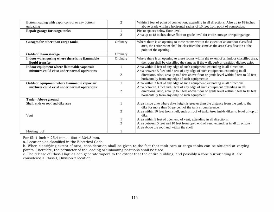
115
Bottom loading with vapor control or any bottom unloading
2 Within 3 feet of point of connection, extending in all directions. Also up to 18 inches above grade within a horizontal radius of 10 feet from point of connection.
Repair garage for cargo tanks 1 2
Pits or spaces below floor level. Area up to 18 inches above floor or grade level for entire storage or repair garage.
Garages for other than cargo tanks Ordinary Where there is an opening to these rooms within the extent of an outdoor classified area, the entire room shall be classified the same as the area classification at the point of the opening.
Outdoor drum storage Ordinary Indoor warehousing where there is no flammable
liquid transfer Ordinary Where there is an opening to these rooms within the extent of an indoor classified area,
the room shall be classified the same as if the wall, curb or partition did not exist. Indoor equipment where flammable vapor/air
mixtures could exist under normal operations 1
2
Area within 5 feet of any edge of such equipment, extending in all directions. Area between 5 feet and 8 feet of any edge of such equipment, extending in all
directions. Also, area up to 3 feet above floor or grade level within 5 feet to 25 feet horizontally from any edge of such equipment.c
Outdoor equipment where flammable vapor/air mixtures could exist under normal operations
1
2
Area within 3 feet of any edge of such equipment, extending in all directions. Area between 3 feet and 8 feet of any edge of such equipment extending in all
directions. Also, area up to 3 feet above floor or grade level within 3 feet to 10 feet horizontally from any edge of such equipment.
Tank—Above ground Shell, ends or roof and dike area Vent Floating roof
1
2
1 2
1
Area inside dike where dike height is greater than the distance from the tank to the
dike for more than 50 percent of the tank circumference. Area within 10 feet from shell, ends or roof of tank. Area inside dikes to level of top of
dike. Area within 5 feet of open end of vent, extending in all directions. Area between 5 feet and 10 feet from open end of vent, extending in all directions. Area above the roof and within the shell
For SI: 1 inch = 25.4 mm, 1 foot = 304.8 mm. a. Locations as classified in the Electrical Code. b. When classifying extent of area, consideration shall be given to the fact that tank cars or cargo tanks can be situated at varying points. Therefore, the perimeter of the loading or unloading positions shall be used. c. The release of Class I liquids can generate vapors to the extent that the entire building, and possibly a zone surrounding it, are considered a Class I, Division 2 location.

116
3403.6.3 Testing. Unless tested in accordance with the applicable section of ANSI B31.9, piping, before being covered, enclosed or placed in use, shall be hydrostatically tested to 150 percent of the maximum anticipated operating pressure of the system, or pneumatically tested to 110 percent of the maximum anticipated pressure of the system, but not less than 15 pounds per square gauge (psig) (103.4 kPa) at the highest point of the system. This test shall be maintained for a sufficient time period to complete visual inspection of joints and connections. For a minimum of 60 minutes, there shall be no leakage or permanent distortion. Pneumatic testing shall be conducted using an inert gas, except that air may be used if the piping system does not contain flammable or combustible liquid vapors. Piping system tests shall be conducted at the owner’s risk by his or her representative before a representative of the department. Care shall be exercised to ensure that these pressures are not applied to vented storage tanks. Such storage tanks shall be tested independently from the piping.
3403.6.3.1 Existing piping. Existing piping shall be tested in accordance with this section, upon a determination by the commissioner that such piping may be leaking. Piping that could contain flammable or combustible liquid vapors shall not be tested pneumatically, except that vapor-recovery piping may be tested pneumatically using an inert gas. Such tests shall be conducted at the owner’s risk by his or her representative.
3403.6.4 Protection from vehicles. Posts or other approved means shall be provided in accordance with Section 312 to protect piping, valves, fittings or ancillary equipment subject to vehicular damage.
3403.6.5 Protection from corrosion and galvanic action. Where subject to external corrosion, piping, related fluid-handling components and supports for both underground and aboveground applications shall be fabricated from noncorrosive materials, coated or otherwise provided with corrosion protection. Dissimilar metallic parts that promote galvanic action shall not be joined.
3403.6.6 Valves. Piping systems shall contain a sufficient number of manual control valves and check valves to operate the system properly and to protect the facility under both normal and emergency conditions. Piping systems in connection with pumps shall contain a sufficient number of such valves to control properly the flow of liquids in normal operation and in the event of physical damage or fire exposure.
3403.6.6.1 Backflow protections. Connections to pipelines or piping by which tank cars, cargo tanks, or marine vessels or other equipment discharge liquids into storage tanks shall be provided with check valves or block valves for automatic protection against backflow where the piping arrangement is such that backflow from the system is possible. Where loading and unloading is done through a common pipe system, a check valve is not required except as required by the applicable provisions of the New York State Department of Environmental Conservation regulations, as set forth in 6 NYCRR Section 613.3(c)(4). However, a block valve shall be provided which is located so as to be readily accessible or remotely operable. 3403.6.6.2 Manual drainage. Manual drainage-control valves shall be located at approved locations remote from the tanks, diked area, drainage system and impounding basin to ensure their operation in a fire condition.
3403.6.7 Connections. Aboveground tanks with connections located below normal liquid level shall be provided with internal or external isolation valves located as close as practical to the shell of the tank. Except for liquids whose chemical characteristics are incompatible with steel, such valves, when external, and their connections to the tank shall be of steel.

117
3403.6.8 Piping supports. Piping systems shall be substantially supported and protected from physical damage and designed to accommodate settlement, vibration, expansion, contraction or exposure to fire. The supports shall be constructed of steel, concrete or other approved noncombustible material. 3403.6.9 Flexible joints. Flexible joints shall be listed and approved and shall be installed on underground liquid, vapor and vent piping at all of the following locations:
1. Where piping connects to underground tanks. 2. Where piping ends at pump islands and vent risers. 3. At points where differential movement in the piping can occur.
3403.6.9.1 Fiberglass-reinforced plastic piping. Fiberglass-reinforced plastic piping is not required to be provided with flexible joints in locations where both of the following conditions are present:
1. Piping does not exceed 4 inches (102 mm) in diameter. 2. Piping has a straight run of not less than 4 feet (1219 mm) on one side of the
connection when such connections result in a change of direction. 3403.6.9.1.1 Flexible joints. In lieu of the minimum 4-foot (1219 mm) straight run
length required in Section 3403.6.9.1(2), approved and listed flexible joints are allowed to be used under dispensers and suction pumps, at submerged pumps and tanks, and where vents extend aboveground.
3403.6.10 Pipe joints. Joints shall be liquid tight and shall be welded, flanged or threaded except that listed flexible connectors are allowed in accordance with Section 3403.6.9. Threaded or flanged joints shall fit tightly by using approved methods and materials for the type of joint. Joints in piping systems used for Class I liquids shall be welded when located in concealed spaces within buildings or structures. Nonmetallic joints shall be subject to the approval of the commissioner and shall be installed in accordance with the manufacturer’s instructions. Pipe joints that are dependent on the friction characteristics or resiliency of combustible materials for liquid tightness of piping shall not be used in buildings or structures. Piping shall be secured to prevent disengagement at the fitting. 3403.6.11 Bends. The bending of pipe and tubing shall be performed in accordance with ANSI B31.9. 3403.6.12 Contents. Piping system components shall be documented as being compatible with the liquid to which such components will be exposed. Such documentation shall be approved and submitted to the department upon request.
FC 3404 Storage 3404.1 General. Flammable and combustible liquids in containers and tanks shall be stored in accordance with this section, Chapter 27 and the New York State Department of Environmental Conservation regulations, as set forth in 6 NYCRR Parts 596, 598, 599, 612, 613 and 614.
3404.1.1 Aboveground storage prohibited. Except as specifically authorized in Section 3406, it shall be unlawful to store flammable liquids in an aboveground storage tank. 3404.1.2 Tank capacity limitations. Except at a bulk plant or terminal or as otherwise specified in this chapter, the capacity of flammable and combustible liquid storage tanks shall not exceed the amounts set forth in Sections 3404.1.2.1 through 3404.1.2.4.
3404.1.2.1 Underground flammable liquid tanks. Individual underground flammable liquid storage tanks shall not exceed a capacity of 4,000 gallons (15 140 L). The aggregate capacity of underground flammable liquid storage tanks at a premises shall not exceed 20,000 gallons (75 700 L).

118
3404.1.2.2 Underground combustible liquid tanks. Individual underground combustible liquid storage tanks shall not exceed a capacity of 12,000 gallons (45 420 L). The aggregate capacity of underground combustible liquid storage tanks at a premises shall not exceed 40,000 gallons (151 400 L). 3404.1.2.3 Aboveground, outdoor combustible liquid tanks. The aggregate capacity of aboveground combustible liquid tanks installed outdoors at a premises shall not exceed 30,000 gallons (113 550 L). 3404.1.2.4 Aboveground, indoor combustible liquid tanks. The aggregate capacity of aboveground combustible liquid tanks installed indoors shall not exceed 20,000 gallons (75 700 L).
3404.2 Tank storage. The provisions of this section shall apply to: 1. The storage of flammable liquids in stationary aboveground tanks located outdoors
and underground tanks. 2. The storage of combustible liquids in stationary aboveground tanks indoors and
outdoors, and underground tanks. 3. Existing storage tank installations at bulk plants and terminals which have not been
used for the storage of flammable or combustible liquids for a period in excess of 2 years from the date of completion of construction of the tank structure, if the tank is to be placed in service.
3404.2.1 Change of tank contents. Tanks subject to change in contents shall be subject to the approval of the commissioner and in accordance with this chapter, including Section 3404.2.7. Prior to a change in contents, the commissioner may require testing of a tank for leaks and documentation of compatibility. Tanks that have previously contained Class I liquids shall not be loaded with Class II or Class III liquids until such tanks and all piping, pumps, hoses and meters connected thereto have been completely drained and flushed. 3404.2.2 Use of cargo tanks, tank cars, barges and marine vessels as storage tanks. Cargo tanks, tank cars, barges and marine vessels shall not be used as storage tanks.
Exception: A barge or marine vessel moored or anchored to privately owned waterfront property storing fuel oil to be used on such waterfront property, when the barge or vessel is located within the bulkhead line and the riparian ownership to the bulkhead line is under the same ownership as the waterfront property, the fuel oil is used only by the owner of such barge or vessel and the fuel oil is used beyond a radius of 200 feet (60 960mm) from the waterfront. Fuel oil stored shall have the specific gravity of not more than 16 degrees Baume. Such barges and marine vessels shall be located wholly within the bulkhead line and in such a position as not to constitute an encumbrance to navigation, and shall be constructed, equipped and protected against fire in compliance with the requirements of the commissioner.
3404.2.3 Labeling and signs. Labeling and signs for storage tanks and storage tank areas shall comply with the requirements of Sections 3404.2.3.1 and 3404.2.3.2.
3404.2.3.1 Smoking and open flame. Signs shall be posted in storage areas prohibiting open flames and smoking. Signs shall comply with the requirements of Section 3403.5. 3404.2.3.2 Label or placard. Tanks more than 100 gallons (379 L) in capacity, which are used for the storage of Class I, II or IIIA liquids, shall bear a label and placard identifying the material therein. Placards shall be in accordance with NFPA 704.
Exception: Tanks located underground. 3404.2.4 Sources of ignition. Open flames are prohibited in storage areas in accordance with Section 2703.7.

119
3404.2.5 Explosion control. Explosion control shall be provided in accordance with Section 911. 3404.2.6 Separation from incompatible materials. Flammable and combustible liquids shall be stored separated from incompatible materials, in accordance with Section 2703.9.8. 3404.2.7 Design and installation requirements for tanks. Tanks shall be designed, constructed and installed in accordance with NFPA 30. Each tank shall bear a permanent nameplate or marking indicating the standard used as the basis of design.
3404.2.7.1 Materials used in tank construction. The materials used in tank construction shall be in accordance with NFPA 30. 3404.2.7.2 Pressure limitations for tanks. Tanks shall be designed for the pressures to which they will be subjected in accordance with NFPA 30. 3404.2.7.3 Tank vents for normal venting. Tank vents for normal venting shall be installed and maintained in accordance with Sections 3404.2.7.3.1 through 3404.2.7.3.6.
3404.2.7.3.1 Vent lines. Vent lines from tanks shall not be used for purposes other than venting unless approved. 3404.2.7.3.2 Vent-line flame arresters and venting devices. Vent-line flame arresters and venting devices shall be installed in accordance with their listings. Use of flame arresters in piping systems shall be in accordance with API 2028. 3404.2.7.3.3 Vent pipe outlets. Vent pipe outlets shall be located such that the vapors are released at a safe point outdoors and not less than 15 feet (4572 mm) above the adjacent ground level. Vapors shall be discharged upward or horizontally away from adjacent walls to assist in vapor dispersion. Vent outlets shall be located such that flammable or combustible vapors will not be trapped by eaves or other obstructions and shall be at least 10 feet (3048 mm) from building openings or lot lines. 3404.2.7.3.4 Installation of vent piping. Vent piping shall be designed, sized, constructed and installed in accordance with Section 3403.6. Vent pipes shall be installed such that they will drain toward the tank without sags or traps in which liquid can collect. Vent pipes shall be installed in such a manner so as not to be subject to physical damage or vibration. 3404.2.7.3.5 Manifolding. Tank vent piping shall not be manifolded unless required for special purposes such as vapor recovery, vapor conservation or air pollution control.
3404.2.7.3.5.1 Aboveground tanks. For aboveground tanks, manifolded vent pipes shall be adequately sized to prevent system pressure limits from being exceeded when manifolded tanks are subject to the same fire exposure. 3404.2.7.3.5.2 Underground tanks. For underground tanks, manifolded vent pipes shall be sized to prevent system pressure limits from being exceeded when manifolded tanks are filled simultaneously. 3404.2.7.3.5.3 Tanks storing Class I liquids. Vent piping for tanks storing Class I liquids shall not be manifolded with vent piping for tanks storing Class II and III liquids unless positive means are provided to prevent the vapors from Class I liquids from entering tanks storing Class II and III liquids, to prevent contamination and possible change in classification of less volatile liquid.
3404.2.7.3.6 Tank venting for tanks and pressure vessels storing Class IB and IC liquids. Tanks and pressure vessels storing Class IB or IC liquids shall be equipped with venting devices which shall remain closed except when venting under pressure or vacuum conditions, or with listed flame arresters. The vents

120
shall be installed and maintained in accordance with Section 2.2.5.1 of NFPA 30 or API 2000.
3404.2.7.4 Emergency venting. Aboveground tanks shall be equipped with additional venting that will relieve excessive internal pressure caused by exposure to fires. Emergency vents shall not discharge indoors. The venting shall be installed and maintained in accordance with Section 2.2.5.2 of NFPA 30.
Exception: Tanks storing Class IIIB liquids that are larger than 12,000 gallons (45 420 L) in capacity, located outdoors and not within the diked area or the drainage path of Class I or II liquids, do not require emergency relief venting.
3404.2.7.5 Tank openings other than vents. Tank openings for other than vents shall comply with the requirements of Sections 3404.2.7.5.1 through 3404.2.7.5.8.
3404.2.7.5.1 Connections below liquid level. Connections for tank openings below the liquid level shall be liquid tight. 3404.2.7.5.2 Filling, emptying and vapor recovery connections. Filling, emptying and vapor recovery connections to tanks shall be located outdoors at a location free from sources of ignition and not less than 10 feet (3048 mm) away from building openings or lot lines. Such openings shall be provided with a liquid-tight cap which shall be closed when not in use and properly identified. 3404.2.7.5.3 Piping, connections and fittings. Piping, connections, fittings and other appurtenances shall be installed in accordance with Section 3403.6. 3404.2.7.5.4 Manual gauging. Openings for manual gauging, if independent of the fill pipe, shall be provided with a liquid-tight cap or cover. Covers shall be kept closed when not gauging. Openings for manual gauging shall not be permitted for tanks installed indoors. 3404.2.7.5.5 Fill pipes and discharge lines. For top-loaded tanks, a metallic fill pipe shall be designed and installed to minimize the generation of static electricity by terminating the pipe within 6 inches (152 mm) of the bottom of the tank, and it shall be installed in a manner which avoids excessive vibration.
3404.2.7.5.5.1 Class I liquids. For Class I liquids other than crude oil, gasoline and asphalt, the fill pipe shall be designed and installed in a manner which will minimize the possibility of generating static electricity by terminating within 6 inches (152 mm) of the bottom of the tank. 3404.2.7.5.5.2 Underground tanks. For underground tanks, fill pipe and discharge lines shall enter only through the top. Fill lines shall be sloped toward the tank. Underground tanks for Class I liquids shall be equipped with a tight fill device for connecting the fill hose to the tank.
3404.2.7.5.6 Location of connections. Filling, withdrawal and vapor-recovery connections that are made and broken shall be located outdoors at a location away from sources of ignition and not less than 5 feet (1524 mm) away from building openings. Such connections shall be closed and liquid tight when not in use and shall be properly identified. 3404.2.7.5.7 Protection against vapor release. Tank openings provided for purposes of vapor recovery shall be protected against vapor release by means of a spring-loaded check valve or dry-break connections, or other approved device, unless the opening is a pipe connected to a vapor processing system. Openings designed for combined fill and vapor recovery shall also be protected against vapor release unless connection of the liquid delivery line to the fill pipe simultaneously connects the vapor recovery line. Connections shall be vapor tight.

121
3404.2.7.5.8 Overfill prevention. An approved means or method in accordance with Section 3404.2.9.6.6 shall be provided to prevent the overfill of all flammable and combustible liquid storage tanks.
3404.2.7.6 Repair or alteration of tanks and piping. The repair or alteration, including welding, cutting and hot tapping of storage tanks and piping that have been placed in service, shall be in accordance with NFPA 30. Hot tapping shall only be permitted with the approval of the commissioner. 3404.2.7.7 Design of supports. The design of the supporting structure for tanks shall be in accordance with the construction codes, including the Building Code and NFPA 30. 3404.2.7.8 Locations subject to flooding. When a tank is located in an area where it is subject to buoyancy because of a rise in the water table, flooding or accumulation of water from fire suppression operations, the tank shall be secured from movement in accordance with Sections 2.3.2.6 and 2.3.3.5 of NFPA 30. 3404.2.7.9 Corrosion protection. Where subject to external corrosion, tanks shall be fabricated from corrosion-resistant materials, coated or provided with corrosion protection in accordance with Section 2.2.6.1 of NFPA 30 and the New York State Department of Environmental Conservation regulations, as set forth in 6 NYCRR Part 614. 3404.2.7.10 Leak reporting. A consistent or accidental loss of liquid, or other indication of a leak from a tank system, shall be reported immediately to the department and other authorities having jurisdiction.
3404.2.7.10.1 Leaking tank disposition. Leaking tanks shall be promptly emptied, repaired and returned to service, sealed in place or removed in accordance with Section 3404.2.13 or 3404.2.14.
3404.2.7.11 Tank lining. Steel tanks are allowed to be lined only for the purpose of protecting the interior from corrosion or providing compatibility with a material to be stored. Only those liquids tested for compatibility with the lining material are allowed to be stored in lined tanks. Tank lining shall not be used for purposes of repairing a tank.
3404.2.8 Reserved. 3404.2.9 Aboveground tanks. Aboveground storage of combustible liquids in tanks shall comply with the requirements of Section 3404.2 and Sections 3404.2.9.1.2 through 3404.2.9.6.10. Except as specifically authorized in Section 3406, the storage of flammable liquid in aboveground storage tanks is prohibited.
3404.2.9.1 Reserved. 3404.2.9.1.1 Reserved. 3404.2.9.1.2 Foam fire protection system installation. Where foam fire protection is approved for a required fire extinguishing system pursuant to this chapter, it shall be designed and installed in accordance with NFPA 11 and NFPA 11A.
3404.2.9.1.2.1 Foam storage. Where foam fire protection is approved for a required fire extinguishing system pursuant to this chapter, the foam-producing materials shall be stored on the premises.
3404.2.9.1.3 Fire protection of supports. Supports or pilings for aboveground tanks storing Class I, II or IIIA liquids elevated more than 12 inches (305 mm) above grade shall have a fire-resistance rating of not less than 2 hours in accordance with the fire exposure criteria specified in ASTM E 1529.
Exception: Structural supports tested as part of a protected aboveground tank in accordance with UL 2085.

122
3404.2.9.1.4 Inerting of tanks with boilover liquids. Liquids with boilover characteristics shall not be stored in fixed roof tanks larger than 150 feet (45 720 mm) in diameter unless an approved gas enrichment or inerting system is provided on the tank.
3404.2.9.2 Supports, foundations and anchorage. Supports, foundations and anchorages for aboveground tanks shall be designed and constructed in accordance with NFPA 30 and the construction codes, including the Building Code. 3404.2.9.3 Stairs, platforms and walkways. Stairs, platforms and walkways shall be of noncombustible construction and shall be designed and constructed in accordance with NFPA 30 and the construction codes, including the Building Code. 3404.2.9.4 Aboveground tank overfill prevention. Aboveground tanks shall not be filled in excess of 95 percent of their capacity. An approved overfill prevention system shall be provided for each tank. During tank-filling operations, the system shall automatically shut off the flow of liquid to the tank when the quantity of liquid in the tank reaches 95 percent of tank capacity. For rigid hose liquid-delivery systems, an approved means shall be provided to empty the fill hose into the tank after the automatic shutoff device is activated. 3404.2.9.5 Outdoor aboveground tanks. Outdoor aboveground tanks shall comply with the requirements of Sections 3404.2.9.5.1 through 3404.2.9.5.3.
3404.2.9.5.1 Locations of aboveground tanks. Outdoor aboveground tanks shall be located in accordance with Sections 3404.2.9.5.1.1 through 3404.2.9.5.1.5, as applicable.
3404.2.9.5.1.1 Location of tanks with pressures 2.5 psig or less. Aboveground tanks operating at pressures not exceeding 2.5 psig (17.2 kPa) for storage of Class I, II or IIIA liquids, which are designed with a floating roof or a weak roof-to-shell seam, or equipped with emergency venting devices limiting pressure to 2.5 psig (17.2 kPa), shall be located in accordance with Table 2.3.2.1.1(a) of NFPA 30.
Exceptions: 1. Vertical tanks having a weak roof-to-shell seam and storing Class IIIA
liquids are allowed to be located at one-half the distances specified in Table 2.3.2.1.1(a) of NFPA 30, provided the tanks are not within a diked area or drainage path for a tank storing Class I or II liquids.
2. Liquids with boilover characteristics and unstable liquids in accordance with Sections 3404.2.9.5.1.4 and 3404.2.9.5.1.5.
3. For protected aboveground tanks in accordance with Section 3404.2.9.6, the distances in Table 2.3.2.1.1(b) of NFPA 30 shall apply and shall be reduced by one-half, but not to less than 5 feet (1524 mm).
3404.2.9.5.1.2 Location of tanks with pressures exceeding 2.5 psig. Aboveground tanks for the storage of Class I, II or IIIA liquids operating at pressures exceeding 2.5 psig (17.2 kPa) or equipped with emergency venting allowing pressures to exceed 2.5 psig (17.2 kPa) shall be located in accordance with Table 2.3.2.1.2 of NFPA 30.
Exception: Liquids with boilover characteristics and unstable liquids in accordance with Sections 3404.2.9.5.1.4 and 3404.2.9.5.1.5.
3404.2.9.5.1.3 Location of tanks for boilover liquids. Aboveground tanks for storage of liquids with boilover characteristics shall be located in accordance with Table 2.3.2.1.3 of NFPA 30.

123
3404.2.9.5.1.4 Location of tanks for unstable liquids. Aboveground tanks for the storage of unstable liquids shall be located in accordance with Table 2.3.2.1.4 of NFPA 30. 3404.2.9.5.1.5 Location of tanks for Class IIIB liquids. Aboveground tanks for the storage of Class IIIB liquids, excluding unstable liquids, shall be located in accordance with Table 2.3.2.1.5 of NFPA 30, except when located within a diked area or drainage path for a tank or tanks storing Class I or II liquids. Where a Class IIIB liquid storage tank is within the diked area or drainage path for a Class I or II liquid, distances required by Section 3404.2.9.5.1.2 shall apply.
3404.2.9.5.2 Separation between adjacent stable or unstable liquid tanks. The separation between tanks containing stable liquids shall be in accordance with Table 2.3.2.2.1 of NFPA 30. Where tanks are in a diked area containing Class I or II liquids, or in the drainage path of Class I or II liquids, and are compacted in three or more rows or in an irregular pattern, the commissioner may require greater separation than specified in Table 2.3.2.2.1 of NFPA 30 or other means to make tanks in the interior of the pattern accessible for firefighting purposes. The separation between tanks containing unstable liquids shall not be less than one-half the sum of their diameters.
Exception: Tanks used for storing Class IIIB liquids are allowed to be spaced 3 feet (914 mm) apart unless within a diked area or drainage path for a tank storing Class I or II liquids.
3404.2.9.5.3 Separation between adjacent tanks containing flammable or combustible liquids and LPG. The minimum horizontal separation between an LPG container and a Class I, II or IIIA liquid storage tank shall be 20 feet (6096 mm) except in the case of Class I, II or IIIA liquid tanks operating at pressures exceeding 2.5 psig (17.2 kPa) or equipped with emergency venting allowing pressures to exceed 2.5 psig (17.2 kPa), in which case the provisions of Section 3404.2.9.5.2 shall apply. An approved means shall be provided to prevent the accumulation of Class I, II or IIIA liquids under adjacent LPG containers such as by dikes, diversion curbs or grading. When flammable or combustible liquid storage tanks are within a diked area, the LPG containers shall be outside the diked area and at least 10 feet (3048 mm) away from the centerline of the wall of the diked area.
Exception: Horizontal separation is not required between LPG containers and underground flammable and combustible liquid tanks.
3404.2.9.6 Additional requirements for protected aboveground tanks. In addition to the requirements of this chapter for aboveground tanks, the installation of protected aboveground tanks shall be in accordance with Sections 3404.2.9.6.1 through 3404.2.9.6.10.
3404.2.9.6.1 Tank construction. The construction of a protected aboveground tank and its primary tank shall be in accordance with Section 3404.2.7. 3404.2.9.6.2 Normal and emergency venting. Normal and emergency venting for protected aboveground tanks shall be provided in accordance with Sections 3404.2.7.3 and 3404.2.7.4. The vent capacity reduction factor shall not be allowed. 3404.2.9.6.3 Flame arresters. Approved flame arresters or pressure vacuum breather valves shall be installed in normal vents. 3404.2.9.6.4 Secondary containment. Protected aboveground tanks shall be provided with secondary containment, drainage control or diking in accordance

124
with Section 2704.2 and 6 NYCRR Part 613.3(c)(6). A means shall be provided to establish the integrity of the secondary containment in accordance with NFPA 30. 3404.2.9.6.5 Vehicle impact protection. Where protected aboveground tanks, piping, electrical conduit or dispensers are subject to vehicular impact, they shall be protected therefrom, either by having the impact protection incorporated into the system design in compliance with the impact test protocol of UL 2085, or by meeting the provisions of Section 312, or where necessary, a combination of both. Where posts or other approved barriers are provided, they shall be independent of each aboveground tank. 3404.2.9.6.6 Overfill prevention sign. A durable sign shall be conspicuously posted on or immediately adjacent to the fill point for the tank, setting forth the filling procedure and the tank calibration chart. The filling procedure shall require the person filling the tank to determine the gallonage (literage) required to fill it to 90 percent of capacity before commencing the fill operation. 3404.2.9.6.7 Fill pipe connections. The fill pipe shall be provided with a means for making a direct connection to the cargo tank’s fuel delivery hose so that the delivery of fuel by means of a liquid-tight connection is not exposed to the open air during the filling operation. Where any portion of the fill pipe exterior to the tank extends below the level of the top of the tank, a check valve shall be installed in the fill pipe not more than 12 inches (305 mm) from the fill hose connection. 3404.2.9.6.8 Spill containers. A spill container having a capacity of not less than 15 gallons (56.8 L) shall be provided for each fill connection. For tanks with a top fill connection, spill containers shall be noncombustible and shall be fixed to the tank and equipped with a manual drain valve that drains into the primary tank. For tanks with a remote fill connection, a portable spill container shall be allowed. 3404.2.9.6.9 Tank openings. Tank openings in protected aboveground tanks shall be through the top only. 3404.2.9.6.10 Antisiphon devices. Approved antisiphon devices shall be installed in each external pipe connected to the protected aboveground tank when the pipe extends below the level of the top of the tank.
3404.2.10 Drainage and diking. The area surrounding a tank or group of tanks shall be provided with drainage control or shall be diked to prevent accidental discharge of liquid from endangering adjacent tanks, adjoining property or reaching waterways. The area shall be in compliance with the requirements of the New York State Department of Environmental Conservation regulations, as set forth in 6 NYCRR Section 613.3(c)(6).
Exceptions: 1. For tanks having a capacity of less than 10,000 gallons (37 850 L), the
commissioner may modify these requirements based on an approved technical report which demonstrates that such tank or group of tanks does not constitute a hazard to other tanks, waterways or adjoining property, after consideration of special features such as topographical conditions, nature of occupancy and proximity to buildings or structures on the same or adjacent property, capacity, and construction of proposed tanks and character of liquids to be stored, and nature and quantity of private and public fire protection provided.
2. Drainage control and diking is not required for listed secondary containment tanks.
3404.2.10.1 Volumetric capacity. The volumetric capacity of the diked area shall not be less than the greatest amount of liquid that can be released from the largest tank within the diked area. The capacity of the diked area enclosing more than one

125
tank shall be calculated by deducting the volume of the tanks other than the largest tank below the height of the dike. 3404.2.10.2 Diked areas containing multiple tanks. Diked areas containing multiple tanks shall be subdivided in accordance with NFPA 30. 3404.2.10.3 Protection of piping from exposure fires. Piping shall not pass through adjacent diked areas or impounding basins, unless provided with a sealed sleeve or otherwise protected from exposure to fire. 3404.2.10.4 Combustible materials in diked areas. Diked areas shall be kept free from combustible materials, drums and barrels. 3404.2.10.5 Equipment, controls and piping in diked areas. Pumps, manifolds and fire protection equipment or controls shall not be located within diked areas or drainage basins or in a location where such equipment and controls would be endangered by fire in the diked area or drainage basin. Piping above ground shall be minimized and located as close as practical to the shell of the tank in diked areas or drainage basins.
Exceptions: 1. Pumps, manifolds and piping integral to the tanks or equipment being
served which is protected by intermediate diking, berms, drainage or fire protection, such as water spray, monitors or resistive coating.
2. Fire protection equipment or controls which are appurtenances to the tanks or equipment being protected, such as foam chambers or foam piping and water or foam monitors and hydrants, or hand and wheeled extinguishers.
3404.2.10.6 Dike construction. All dike walls shall be of steel or reinforced concrete, designed to be liquid tight and to withstand a full hydraulic head, and constructed to provide access to and from the diked area. Where stairways or other means are required to provide such access, they shall be constructed of steel. No dike wall shall be higher than 60 percent of the tank height.
3404.2.11 Underground tanks. Underground storage of flammable and combustible liquids in tanks shall comply with the requirements of Section 3404.2 and Sections 3404.2.11.1 through 3404.2.11.5.2.
3404.2.11.1 Contents. Underground tanks shall not store petroleum products containing mixtures of a nonpetroleum nature, such as ethanol or methanol blends, without evidence of compatibility. 3404.2.11.2 Location. Flammable and combustible liquid storage tanks located underground, either outdoors or under buildings, shall be in compliance with the following requirements:
1. Tanks shall be installed so that the external forces exerted from building foundations and support loads are not transmitted to the tanks. The distance from any part of a tank to the nearest wall of any basement, pit, cellar or any property line shall not be less than 3 feet (914 mm). Tanks shall not be placed less than 20 feet (6096 mm) from a subway wall.
2. Tanks shall be installed so that the highest point of the tank is not less than 2 feet (609.6 mm) below the level of the lowest cellar floor of any building within a radius of 10 feet (3048 mm) from the tank. No tank shall be located under a sidewalk or beyond the property line.
3. A minimum distance of 1 foot (305 mm), shell to shell, shall be maintained between underground tanks.
4. Manufacturer's installation instructions. 3404.2.11.3 Depth and cover. Excavation for underground storage tanks shall be made with due care to avoid undermining of foundations of existing structures.

126
Underground tanks shall be set on firm foundations and surrounded with at least 6 inches (152 mm) of noncorrosive inert material, in accordance with the manufacturer's installation instructions. 3404.2.11.4 Overfill protection and prevention systems. Fill pipes shall be equipped with a spill container of not less than 15-gallon (56.8 L) capacity and an approved overfill prevention system to automatically prevent overflow in accordance with NFPA 30 and Section 3404.2.9.4. 3404.2.11.5 Leak prevention. Leak prevention for underground tanks shall comply with the requirements of Sections 3404.2.11.5.1 and 3404.2.11.5.2.
3404.2.11.5.1 Inventory control. Daily inventory records shall be maintained for underground storage tank systems. 3404.2.11.5.2 Leak detection. Underground storage tank systems shall be provided with an approved method of leak detection from any component of the system that is designed and installed in accordance with NFPA 30. Leak detection systems shall be tested at the time of installation at the owner’s risk by his or her representative before a representative of the department.
3404.2.11.6 Periodic tank and piping test. Any underground single-walled flammable or combustible liquid storage tank existing prior to the effective date of this code that is single-walled or is not provided with a leak detection system meeting the requirements of Section 3404.2.11.5.2 shall be precision tested at least once every 5 years.
Exception: Bulk plant and terminal tanks. 3404.2.11.7 Emergency tank and piping system test. The commissioner may require a tank and piping system to be precision tested, pressure tested or tested by other approved method in accordance with this section to determine the condition of the tank or piping or when the commissioner has good cause to believe that a leak exists. Storage systems that may contain flammable or combustible liquid vapor shall not be tested pneumatically. Such tests shall be conducted at the owner’s risk by his or her representative.
3404.2.12 Testing. Tank testing required by Sections 3404.2.12.1 through 3404.2.12.3 shall be at the owner’s risk by his or her representative before a representative of the department.
3404.2.12.1 Acceptance testing. Prior to being placed into service, tanks shall be tested in accordance with Section 2.4 of NFPA 30. 3404.2.12.2 Testing of underground tanks. Underground tanks shall be tested hydrostatically at 15 pounds per square inch (psig)(103.4 kPa), or 150 percent of the maximum anticipated static head pressure, whichever is greater, for the inner tank, and pneumatically or hydrostatically at 5 pounds per square inch (psig)(34.5 kPa) for the annular space (secondary containment tank). When a pneumatic test is allowed, an inert gas shall be used; however, air may be used if the tank does not contain any flammable or combustible liquid vapor. Test pressure shall be maintained for sufficient time to complete visual inspection, but not less than 1 hour. A tank shall be deemed to have passed the test if it shows no evidence of leakage or permanent deformation. 3404.2.12.3 Testing of aboveground tanks. Aboveground tanks shall be tested hydrostatically at 15 pounds per square inch (psig)(103.4 kPa) for the inner tank, and pneumatically or hydrostatically at 5 pounds per square inch (psig)(34.5 kPa) for the annular space (secondary containment tank). When a pneumatic test is allowed, an inert gas shall be used; however, air may be used if the tank does not contain any flammable or combustible liquid vapor. Test pressure shall be maintained for

127
sufficient time to complete visual inspection, but not less than 1 hour. A tank shall be deemed to have passed the test if it shows no evidence of leakage or permanent deformation.
3404.2.13 Out-of-service tanks. Tanks taken out-of-service shall be removed in accordance with Section 3404.2.14, or safeguarded in accordance with Sections 3404.2.13.1 through 3404.2.13.2.3 and API 1604.
Exceptions: 1. Tanks within operating facilities at bulk plants and terminals. 2. Tanks connected to fuel oil burning equipment that is used seasonally or as
one of the fuels in dual-fueled equipment. 3. Tanks that are used for seasonal storage or standby storage.
3404.2.13.1 Underground tanks. Underground tanks taken out-of-service shall comply with the requirements of Sections 3404.2.13.1.2 through 3404.2.13.1.4.
3404.2.13.1.1 Reserved. 3404.2.13.1.2 Out-of-service for 30 days. Underground tanks not used for a period of 30 days or more shall be removed from the premises in accordance with Section 3404.2.14 or safeguarded in compliance with the following requirements:
1. Flammable or combustible liquids shall be removed from the tank and connecting piping.
2. The tank and connecting piping shall be rendered free of flammable and combustible vapors using an inert gas.
3. Except for any active fire extinguishing system piping, the tank and connecting piping, including fill line, gauge opening, vapor return and pump connection, shall be capped or plugged and secured from tampering and the fill connection covered with concrete.
4. Vent lines shall remain open and be maintained in accordance with Sections 3404.2.7.3 and 3404.2.7.4.
3404.2.13.1.3 Out-of-service for 1 year. Underground tanks that have been out-of-service for a period of 1 year or more shall be removed from the premises in accordance with Section 3404.2.14 or sealed in place in compliance with the following requirements:
1. Flammable and combustible liquids shall be removed from the tank and connected piping. 2. The tank and connecting piping shall be rendered free of flammable and
combustible vapors, using an inert gas. 3. All tanks and connecting piping, including fire extinguishing system lines,
fill line, gauge opening, vapor return and pump connection, shall be disconnected, capped or plugged and secured from tampering, and the fill connection sealed with concrete to prevent its use.
4. The tank shall be filled completely with an approved, inert solid material. 3404.2.13.2 Aboveground tanks. Aboveground tanks taken out-of-service shall comply with the requirements of Sections 3404.2.13.2.2 and 3404.2.13.2.3.
3404.2.13.2.1 Reserved. 3404.2.13.2.2 Out-of-service for 30 days. Aboveground tanks not used for a period of 30 days or more shall be removed from the premises in accordance with Section 3404.2.14 or safeguarded in compliance with the following requirements:
1. Tank and connecting piping shall be safeguarded in accordance with Section 3404.2.13.1.2.
2. The tank shall be protected from flotation in accordance with good engineering practice.

128
3404.2.13.2.3 Out-of-service for 1 year. Aboveground tanks that have been out-of-service for a period of 1 year or more shall be removed from the premises in accordance with Section 3404.2.14 or sealed in place in compliance with the following requirements:
1. Flammable and combustible liquids shall be removed from the tank and connected piping.
2. The tank and connecting piping shall be rendered free of flammable and combustible vapors using an inert gas.
3. All piping, including fire extinguishing system lines, fill line, gauge opening, vapor return and pump connection, shall be disconnected, capped or plugged and secured from tampering, and the fill connection sealed with concrete to prevent its use.
4. The tank shall be adequately protected from flotation in accordance with good engineering practice.
5. The tank shall be stenciled with the date that it was sealed in place. 3404.2.14 Removal and disposal of tanks. Removal and disposal of tanks shall comply with the requirements of Sections 3404.2.14.1 and 3404.2.14.2.
3404.2.14.1 Removal. Removal of aboveground and underground tanks shall be in compliance with the following requirements:
1. Flammable and combustible liquids shall be removed from the tank and connecting piping.
2. The tank and connecting piping shall be rendered free of flammable and combustible vapors using an inert gas. 3. Piping at tank openings shall be disconnected. 4. Piping shall be removed from the premises.
Exception: Piping may be sealed in place where the commissioner determines that removal is not practical. Sealed in place piping shall be capped and safeguarded by filling with concrete or other approved material, and the fill connection removed from the fill pipe.
5. Tank openings shall be capped or plugged, leaving a 0.125-inch to 0.25-inch-diameter (3.2 mm to 6.4 mm) opening for pressure equalization. 6. Tanks shall be removed from the premises.
3404.2.14.2 Disposal. Tanks and piping shall be disposed of lawfully. 3404.3 Container storage. Storage of flammable and combustible liquids in closed containers that do not exceed 60 gallons (227 L) in individual capacity, and transfers incidental thereto, shall comply with the requirements of this section. It shall be unlawful to store flammable and combustible liquids in containers with an individual capacity of greater than 60 gallons (227 L).
3404.3.1 Design, construction and capacity of containers. The design, construction and capacity of containers for the storage of flammable and combustible liquids shall be in accordance with this section and Section 4.2 of NFPA 30. It shall be unlawful to store flammable and combustible liquids in portable tanks, intermediate bulk containers and fiber drums.
3404.3.1.1 Approved containers. Only approved containers shall be used. 3404.3.2 Liquid storage cabinets. Where other sections of this code require that liquid containers be stored in storage cabinets, such cabinets and storage shall be in accordance with Sections 3404.3.2.1 through 3404.3.2.3.
3404.3.2.1 Design of storage cabinets. Design of liquid storage cabinets shall be in accordance with this section.
3404.3.2.1.1 Materials. Cabinets shall be listed in accordance with UL 1275.

129
3404.3.2.1.2 Labeling. Cabinets shall be provided with a conspicuous label in red letters on contrasting background which reads: FLAMMABLE—KEEP FIRE AWAY. 3404.3.2.1.3 Doors. Doors shall be well fitted, self-closing and equipped with a three-point latch. 3404.3.2.1.4 Bottom. The bottom of the cabinet shall be liquid tight to a height of at least 2 inches (51 mm).
3404.3.2.2 Capacity. The combined total quantity of liquids in a cabinet shall not exceed 120 gallons (454 L). 3404.3.2.3 Number of storage cabinets. Not more than three storage cabinets shall be located in a single fire area, except that in a Group F occupancy, additional cabinets are allowed to be located in the same fire area if the additional cabinets (or groups of up to three cabinets) are separated from other cabinets or groups of cabinets by at least 100 feet (30 480 mm).
3404.3.3 Indoor storage. Storage of flammable and combustible liquids indoors in containers shall be in accordance with this section.
Exceptions: 1. Liquids in the fuel tanks of motor vehicles, aircraft, watercraft or portable or
stationary engines. 2. The storage of distilled spirits and wines in wooden barrels or casks.
3404.3.3.1 Portable fire extinguishers. Approved portable fire extinguishers shall be provided in accordance with specific sections of this chapter and Section 906. 3404.3.3.2 Incompatible materials. Materials that will react with water or other liquids to produce a hazard shall not be stored in the same room with flammable and combustible liquids in accordance with Section 2703.9.8. 3404.3.3.3 Clear means of egress. Storage of any liquids, including stock for sale, shall not be stored near or be allowed to obstruct physically the route of egress.
3404.3.3.4 Empty containers storage. The storage of empty containers previously used for the storage of flammable or combustible liquids shall be stored as required for filled containers. Containers, when emptied, shall have the covers or plugs immediately replaced in openings, be removed to an outdoor location and, if not cleaned on the premises, the empty containers shall be removed from the premises as soon as practical, but at least daily.
3404.3.3.5 Shelf storage. Shelving shall be of approved noncombustible construction, adequately braced and anchored. Seismic requirements shall be in accordance with the construction codes, including the Building Code.
3404.3.3.5.1 Reserved. 3404.3.3.5.2 Displacement protection. Shelves shall be of sufficient depth and provided with a lip or guard to prevent individual containers from being displaced.
Exception: Shelves in storage cabinets or on laboratory furniture specifically designed for such use.
3404.3.3.5.3 Orderly storage. Shelf storage of flammable and combustible liquids shall be maintained in an orderly manner.
3404.3.3.6 Rack storage. Where storage on racks is allowed elsewhere in this code, a minimum 4-foot-wide (1219 mm) aisle shall be provided between adjacent rack sections and any adjacent storage of liquids. Main aisles shall be a minimum of 8 feet (2438 mm) wide. 3404.3.3.7 Pile or palletized storage. Solid pile and palletized storage in liquid warehouses shall be arranged so that piles are separated from each other by at least 4 feet (1219 mm). Aisles shall be provided and arranged so that no container is more

130
than 20 feet (6096 mm) from an aisle. Main aisles shall be a minimum of 8 feet (2438 mm) wide. 3404.3.3.8 Limited combustible storage. Limited quantities of combustible commodities are allowed to be stored in liquid storage areas where the ordinary combustibles, other than those used for packaging the liquids, are separated from the liquids in storage by a minimum of 8 feet (2438 mm) horizontally, either by open aisles or by open racks, and where protection is provided in accordance with Chapter 9. 3404.3.3.9 Idle combustible pallets. Storage of empty or idle combustible pallets inside an unprotected liquid storage area shall be limited to a maximum pile size of 2,500 square feet (232 m2) and to a maximum storage height of 6 feet (1829 mm). Storage of empty or idle combustible pallets inside a protected liquid storage area shall comply with the requirements of NFPA 13. Pallet storage shall be separated from liquid storage by aisles that are at least 8 feet (2438 mm). 3404.3.3.10 Containers in piles. Containers in piles shall be stacked in such a manner as to provide stability and to prevent excessive stress on container walls. Adequate material-handling equipment shall be available to handle containers safely at the upper tier level.
3404.3.4 Quantity limits for storage. Liquid storage quantity limitations shall comply with the requirements of Sections 3404.3.4.1 through 3404.3.4.5.
3404.3.4.1 Maximum allowable quantity per control area. For occupancies other than Group M wholesale and retail sales uses, indoor storage of flammable and combustible liquids shall not exceed the maximum allowable quantities per control area indicated in Table 2703.1.1(1) and shall not exceed the additional limitations set forth in this section. For Group M occupancy wholesale and retail sales uses, indoor storage of flammable and combustible liquids shall not exceed the maximum allowable quantities per control area indicated in Table 3404.3.4.1, except that no gasoline or flammable liquid motor fuel may be stored in portable containers for wholesale or retail sale. Storage of hazardous production material flammable and combustible liquids in Group H-5 occupancies shall be in accordance with Chapter 18. 3404.3.4.2 Limitations on storage. The quantity of flammable or combustible liquid stored shall be limited by occupancy as follows:
1. Group A, B, E, F, I and S occupancies. Flammable and combustible liquids shall be stored only for lawful uses incidental to the occupancy, including maintenance and operation of equipment, and in quantities not to exceed that which is necessary for such use.
2. Group M occupancies. Flammable and combustible liquids shall be stored only for lawful uses incidental to the occupancy, including maintenance and operation of equipment, and in quantities not to exceed that which is necessary for such use. The maximum allowable quantities for storage in wholesale and retail sales areas shall be in accordance with Section 3404.3.4.1.
3. Group R occupancies. Flammable and combustible liquids shall be stored only for maintenance and operation of equipment, and in quantities not to exceed that which is necessary for such use. Quantities within a dwelling unit shall be stored only for household use and in quantities below permit amounts. It shall be unlawful to store gasoline or other flammable liquid motor fuel within a dwelling unit.
4. Gasoline and other flammable liquid motor fuel. Storage of gasoline and other flammable liquid motor fuel in portable containers in quantities requiring

131
a permit is subject to the approval of the commissioner, regardless of the occupancy classification of the premises.
3404.3.4.3 Quantities exceeding limits for control areas. Quantities exceeding those allowed in control areas set forth in Section 3404.3.4.1 shall be in liquid storage rooms or liquid storage warehouses in accordance with Sections 3404.3.7 and 3404.3.8. 3404.3.4.4 Liquids for maintenance and operation of equipment. In all occupancies, quantities of flammable and combustible liquids requiring a permit pursuant to Section 105.6, used for maintenance purposes and the operation of equipment, shall be stored in liquid storage cabinets in accordance with Section 3404.3.2. Quantities not requiring a permit pursuant to Section 105.6 are allowed to be stored outside of a cabinet when in approved containers and locations. 3404.3.4.5 Citywide permits. No citywide permit authorizing the storage and use of flammable or combustible liquids shall be valid for:
1. The storage or use of gasoline in quantities exceeding 5 gallons (19 L). 2. The storage or use of flammable liquids in quantities exceeding 250 gallons
(946 L). 3. The storage or use of combustible liquids in quantities exceeding 300 gallons
(1136 L). 4. The storage or use of any paint, varnish, or other flammable or combustible
liquid commonly used for painting, varnishing, lacquering, staining, waxing or other finishing operations in quantities exceeding 200 gallons (757 L), except as otherwise limited in Chapter 15 for floor finishing operations.
3404.3.5 Storage in control areas. Storage of flammable and combustible liquids in control areas shall be in accordance with Sections 3404.3.5.1 through 3404.3.5.4.
3404.3.5.1 Storage below grade. Class I liquids shall not be permitted in basements, cellars or other areas below grade. Class II and III liquids shall be allowed to be stored in basements, cellars or other areas below grade provided that such basement, cellar or other below grade area is protected throughout by a sprinkler system, and other fire protection is provided in accordance with Chapter 9 and the construction codes, including the Building Code.
Exception: Class IIIB liquids may be stored in basements, cellars and other areas below grade that are not protected throughout by a sprinkler system when stored in a room or other area that is segregated, vertically and horizontally, from surrounding spaces by a fire separation of not less than 2-hour fire-resistance rating and such room or other area is protected throughout by a sprinkler system.
3404.3.5.2 Storage pile heights. Containers having less than a 30-gallon (114 L) capacity which contain Class I or II liquids shall not be stacked more than 3 feet (914.4 mm) or two containers high, whichever is greater, unless stacked on fixed shelving or otherwise satisfactorily secured. Containers of Class I or II liquids having a capacity of 30 gallons (114 L) or more shall not be stored more than one container high. Containers shall be stored in an upright position. 3404.3.5.3 Storage distance from ceilings and roofs. Piles of containers shall not be stored closer than 3 feet (914 mm) to the nearest beam, chord, girder or other obstruction, and shall be 3 feet (914 mm) below sprinkler deflectors or discharge orifices of water spray or other overhead fire extinguishing system.
3404.3.5.4 Combustible materials. In areas that are inaccessible to the public, Class I, II and IIIA liquids shall not be stored in the same pile or rack section as ordinary combustible commodities unless such materials are packaged together as kits.

132
TABLE 3404.3.4.1 MAXIMUM ALLOWABLE QUANTITY OF FLAMMABLE AND COMBUSTIBLE LIQUIDS
MAXIMUM ALLOWABLE QUANTITY PER CONTROL AREA (gallons)
IN WHOLESALE AND RETAIL SALES USES PER CONTROL
AREAa TYPE OF LIQUID Sprinkleredb per footnote densities and arrangements
Sprinklered per Tables 3404.3.6.3(4)
through 3404.3.6.3(8) and Table
3404.3.7.5.1 and the construction codes,
including the Building Code
Nonsprinklered
Class IA 60 60 30 Class IB, IC, II and IIIA 7,500c 15,000c 1,600
Class IIIB Unlimited Unlimited 13,200
For SI: 1 foot = 304.8 mm, 1 square foot = 0.0929m2, 1 gallon = 3.785 L, 1 gallon per minute per square foot = 40.75 L/min/m2. a. Control areas shall be separated from each other by not less than a 1-hour fire barrier wall. b. To be considered as sprinklered, a building shall be protected throughout by a sprinkler
system with a design providing minimum densities as follows: 1. For uncartoned commodities on shelves 6 feet or less in height where the ceiling height
does not exceed 18 feet, quantities are those permitted with a minimum sprinkler design density of Ordinary Hazard Group 2.
2. For cartoned, palletized or racked commodities where storage is 4 feet 6 inches or less in height and where the ceiling height does not exceed 18 feet, quantities are those permitted with a minimum sprinkler design density of 0.21 gallon per minute per square foot over the most remote 1,500-squarefoot area.
c. Where wholesale and retail sales or storage areas exceed 50,000 square feet in area, the maximum allowable quantities are allowed to be increased by 2 percent for each 1,000 square feet of area in excess of 50,000 square feet, up to a maximum of 100 percent of the table amounts. A control area separation is not required. The cumulative amounts, including amounts attained by having an additional control area, shall not exceed 30,000 gallons.
3404.3.6 Wholesale and retail sales. Flammable and combustible liquids in Group M occupancy wholesale and retail sales shall be in accordance with Sections 3404.3.6.1 through 3404.3.6.5, or NFPA 30 Sections 4.4.3.3, 4.5.6.7, 4.8.2, Tables 4.8.2(a) through (f), and Figures 4.8.2(a) through (d).
3404.3.6.1 Container type. Containers for Class I liquids shall be metal. Exception: In sprinklered buildings, an aggregate quantity of 120 gallons (454 L) of water-miscible Class IB and Class IC liquids is allowed in nonmetallic containers, each having a capacity of 16 ounces (0.473 L) or less.
3404.3.6.2 Container capacity. Containers for Class I liquids shall not exceed a capacity of 5 gallons (19 L).
Exception: Metal containers not exceeding 55 gallons (208 L) are permitted to store up to 240 gallons (908 L) of the maximum allowable quantity per control

133
area of Class IB and IC liquids in a control area. The building shall be protected throughout by a sprinkler system in accordance with Table 3404.3.4.1. The containers shall be provided with plastic caps without cap seals and shall be stored upright. Containers shall not be stacked or stored in racks and shall not be located in areas accessible to the public.
3404.3.6.3 Fire protection and storage arrangements. Fire protection and container storage arrangements shall be in accordance with Table 3404.3.6.3(1) or the following:
1. Storage on shelves shall not exceed 6 feet (1829 mm) in height, and shelving shall be metal.
2. Storage on pallets or in piles greater than 4 feet 6 inches (1372 mm) in height, or where the ceiling exceeds 18 feet (5486 mm) in height, shall be protected by a sprinkler system in accordance with Table 3404.3.6.3(4), and the storage heights and arrangements shall be limited to those specified in Table 3404.3.6.3(2).
3. Storage on racks greater than 4 feet 6 inches (1372 mm) in height, or where the ceiling exceeds 18 feet (5486 mm) in height shall be protected in accordance with Tables 3404.3.6.3(5), 3404.3.6.3(6), 3404.3.6.3(7) and 3404.3.6.3(8) and the construction codes, including the Building Code as appropriate, and the storage heights and arrangements shall be limited to those specified in Table 3404.3.6.3(3).
3404.3.6.3.1 Combustible commodities. Combustible commodities shall not be stored above flammable and combustible liquids.
TABLE 3404.3.6.3(1) MAXIMUM STORAGE HEIGHT IN CONTROL AREA
TYPE OF LIQUID NONSPRINKLERED AREA (feet)
SPRINKLERED AREA (feet)
SPRINKLEREDa
WITH IN-RACK PROTECTION (feet)
Flammable liquids: Class IA Class IB Class IC
4 4 4
4 8 8
4 12 12
Combustible liquids: Class II Class IIIA Class IIIB
6 8 8
8 12 12
12 16 20
For SI: 1 foot = 304.8 mm. a. In-rack protection shall be in accordance with Table 3404.3.6.3(5), 3404.3.6.3(6), 3404.3.6.3(7) or 3404.3.6.3(8) and the construction codes, including the Building Code.
TABLE 3404.3.6.3(2) STORAGE ARRANGEMENTS FOR PALLETIZED OR SOLID-PILE STORAGE IN LIQUID
STORAGE ROOMS AND WAREHOUSES MAXIMUM STORAGE
HEIGHT MAXIMUM QUANTITY PER PILE (gallons)
MAXIMUM QUANTITY PER ROOMa (gallons)
CLASS STORAG ELEVEL
Drums Containersb
(feet) Container
s Containers

134
IA Ground floor Upper floors Basementsd
1 1
Not Allowed
5 5
Not Allowed
3,000 2,000 Not
Allowed
12,000 8,000
Not Allowed
IB Ground floor Upper
1 1
Not Allowed
6.5 6.5
Not Allowed
5,000 3,000 Not
Allowed
15,000 12,000
Not Allowed
IC Ground floor Upper floors Basementsd
1 1
Not Allowed
6.5c 6.5c
Not Allowed
5,000 3,000 Not
Allowed
15,000 12,000
Not Allowed
II Ground floor Upper floors Basementsd
3 3 1
10 10 5
10,000 10,000 7,500
25,000 25,000 7,500
III Ground floor Upper floors Basementsd
5 5 3
20 20 10
15,000 15,000 10,000
50,000 50,000 25,000
For SI: 1 foot = 304.8 mm, 1 gallon = 3.785 L. a. See Section 3404.3.8.1 for unlimited quantities in liquid storage warehouses. b. Storage heights are allowed to be increased for Class IB, IC, II and III liquids in metal
containers having a capacity of 5 gallons or less where an automatic AFFF-water protection system has been approved by the commissioner and the commissioner of buildings.
c. These height limitations are allowed to be increased to 10 feet for containers having a capacity of 5 gallons or less.
d. Basements include cellars and other areas below grade.

135
TABLE 3404.3.6.3(3) MAXIMUM STORAGE HEIGHT
(feet)
MAXIMUM QUANTITY PER ROOM
(gallons)
STORAGE ARRANGEMENTS FOR RACK STORAGE IN LIQUID
STORAGE ROOMS AND WAREHOUSES CLASS
TYPE RACK STORAGE LEVEL
Containers Containers IA Double row
or Single row Ground floor Upper floors Basements
25 15 Not
Allowed
7,500 4,500
Not Allowed
IB IC
Double row or Single row
Ground floor Upper floors Basements
25 15 Not
Allowed
15,000 9,000
Not Allowed
II Double row or Single row
Ground floor Upper floors Basements
25 25 15
24,000 24,000 9,000
III Multirow Double room Single row
Ground floor Upper floors Basements
40 20 20
48,000 48,000 24,000
For SI: 1 foot = 304.8 mm, 1 gallon = 3.785 L.

136
Table 3404.3.6.3 (4) SPRINKLER SYSTEM PROTECTION FOR SOLID-PILE AND PALLETIZED STORAGE OF LIQUIDS IN
CONTAINERS AND PORTABLE TANKSa Storage Conditions Ceiling Sprinkler Design and Demand
Area (square feet) Class Liquid
Container Size and Arrangement
Density (gpm/ft2)
High-temperature Sprinklers
Ordinary Temperature Sprinklers
Maximum spacing
(square feet)
Minimum Hose Stream
Demand (gpm)
Minimum Duration
Sprinklers and Hose Streams (hours)
5 gallons or less, with or without cartons, palletized or solid pileb
0.30 3,000 5,000 100 750 2
IA Containers greater than 5 gallons, on end or side, palletized or solid pile
0.60 5,000 8,000 80 750
5 gallons or less, with or without cartons, palletized or solid pileb
0.30 3,000 5,000 100 500 2
IB, IC and II Containers greater
than 5 gallons on pallets or solid pile, one high
0.25 5,000 8,000 100
II
Containers greater than 5 gallons on pallets or solid pile, more than one high, on end or side
0.60 5,000 8,000 80 750 2
5 gallons or less, with or without cartons, palletized or solid pile
0.25 3,000 5,000 120 500 1
Containers greater than 5 gallons on pallets or solid pile, on end or sides, up to three high
0.25 3,000 5,000 120 500 1
III
Containers greater than 5 gallons, on pallets or solid pile, on end or sides, up to 18 feet high
0.35 3,000 5,000 100 750 2
a. The design area contemplates the use of Class II standpipe systems. Where Class I standpipe systems are used, the area of application shall be increased by 30 percent without revising density.
b. For storage heights above 4 feet or ceiling heights greater than 18 feet, an approved engineering design shall be provided in accordance with Section 104.7.2.

137
Table 3404.3.6.3 (5) SPRINKLER SYSTEM PROTECTION REQUIREMENTS FOR RACK STORAGE OF LIQUIDS IN CONTAINERS OF 5-GALLON CAPACITY
OR LESS WITH OR WITHOUT CARTONS ON CONVENTIONAL WOOD PALLETSa Ceiling Sprinkler Design and
Demand In-rack Sprinkler Arrangement and Demand
Area (square feet)
30 psi (standard orifice)
Class Liquid
Density (gpm/ft2)
High-temperature sprinklers
Ordinary temperature sprinklers
Max. spacing
(ft2/head) Racks up to 9 feet deep Racks ore than 9 feet
to 12 feet deep
14 psi (large
orifice) Number of sprinklers
operating
Min. Hose Stream
Demand (gpm)
Min. Duration Sprinkler and Hose Stream (hours)
I (max. 25-foot
height) Option 1
0.40 3,000 5,000 80
1. Ordinary temperature, quick-response sprinklers, maximum 8 feet 3 inches horizontal spacing
2. One line sprinklers above each level of storage
3. Locate in longitudinal flue space, staggered vertical
4. Shields required where multilevel
1. Ordinary temperature, quick-response sprinklers, maximum 8 feet 3 inches horizontal spacing
2. One line sprinklers above each level of storage
3. Locate in transverse flue spaces, staggered vertical and within 20 inches of aisle.
4. Shields required where multilevel
30 psi (0.5-inch orifice)
1. 8 sprinklers if only 1 level
2. 6 sprinklers each on 2 levels if only 2 levels
3. 6 sprinklers each on top 3 levels, if there or more levels
4. Hydraulically most remote
750 2
I (max. 25-foot
height) Option 2
0.55 2,000b Not
Applicable 100 See 1 through 4 above See 1 through 4 above
14 psi (0.53-in orifice)
See 1 through 4 above 500 2
I and II (max. 14-foot
storage height) (max.3 tiers)
0.55c 2,000b,d Not
Applicable 100
Not Applicable None for max. 6-foot-deep racks
Not Applicable 500 2
II (max. 25-foot
height) 0.30 3,000 5,000 100
1. Ordinary temperature sprinklers 8 feet apart horizontally
2. One line sprinklers b/w levels at nearest 10-foot vertical intervals
3. Locate in longitudinal flue spaces, staggered vertical.
4. Shields required where multilevel
1. Ordinary temperature sprinklers 8 feet apart horizontally
2. Two lines b/w levels at nearest 10-foot vertical intervals
3. Locate in transverse flue spaces, staggered vertical and within 20 inches of aisle.
4. Shields required where multilevel
30 psi
Hydraulically most remote-6 sprinklers at
each level, up to a max. of 3 levels
750 2
III (40-foot height)
0.25 3,000 5,000 120 Same as for Class II liquids Same as for Class II liquids 30 psi Same as for Class II
liquids 500 2
a. The design area contemplates the use of Class II standpipe systems. Where Class I standpipe systems are used, the area of application shall be increased by 30 percent without revising density. b. When the installation uses listed or approved extra-large orifices, high-temperature quick-response or standard element sprinklers, such spaces may be provided with a maximum 30-foot ceiling height provided minimum 7.5-foot aisles are maintained. c. For friction lid cans and other metal containers equipped with plastic nozzles or caps, the density shall be increased to 0.65 gpm per square foot using listed or approved extra-large orifice, high-temperature quick-response sprinklers. d. When the installation uses listed or approved extra-large orifice, high-temperature quick-response or standard element sprinklers, such spaces may be provided with a maximum 18-foot ceiling height provided minimum 7.5-foot aisles are maintained and only metal containers are stored.

138
Table 3404.3.6.3 (6)
SPRINKLER SYSTEM PROTECTION REQUIREMENTS FOR RACK STORAGE OF LIQUIDS IN CONTAINERS GREATER THAN 5-GALLON CAPACITYa Ceiling Sprinkler Design and Demand In-rack Sprinkler Arrangement and Demand
Area (square feet)
Class Liquid
Density (gpm/ft2)
High-temperature sprinklers
Ordinary temperature sprinklers
Max. spacing
(ft2/head) On-side storage racks up to 9-foot-
deep racks On-end storage (on pallets) up to
9-foot-deep racks
Min. nozzle
pressure Number of sprinklers
operating
Min. Hose
Stream Demand (gpm)
Min. Duration Sprinkler and Hose Stream (hours)
IA (max. 25-foot
height) 0.60 3,000 5,000 80
1. Ordinary temperature sprinklers 8 feet apart horizontally
2. One line sprinklers above each tier of storage
3. Locate in longitudinal flue space, staggered vertical
4. Shields required where multilevel
1. Ordinary temperature sprinklers 8 feet apart horizontally
2. One line sprinklers above each level of storage
3. Locate in longitudinal flue space, staggered vertical
4. Shields required where multilevel
30 psi Hydraulically most
remote- 6 sprinklers at each level
1,000 2
IB, IC and II (max. 25-foot
height) 0.60 3,000 5,000 100
1. See 1 above 2. One line sprinklers every 3 tiers
of storage 3. See 3 above 4. See 4 above
See 1 through 4 above 30 psi Hydraulically most
remote 750 2
III (max. 40-foot
height) 0.25 3,000 5,000 120
1. See 1 above 2. One line sprinklers every sixth
level (maximum) 3. See 3 above 4. See 4 above
1. See 1 above 2. One line sprinklers every third
level (maximum) 3. See 3 above 4. See 4 above
15 psi Hydraulically most
remote 500 1
a. The design assumes the use of Class II standpipe systems. Where a Class I standpipe system is used, the area of application shall be increased by 30 percent without revising density.
Table 3404.3.6.3 (7)
AUTOMATIC AFFF WATER PROTECTION REQUIREMENTS FOR RACK STORAGE OF LIQUIDS IN CONTAINERS GREATER THAN 5-GALLON CAPACITYa,b
Ceiling Sprinkler Design and Demand In-rack Sprinkler Arrangement and Demandc
Area (square feet) Class Liquid
Density (gpm/ft2)
High-temperature sprinklers
Ordinary temperature sprinklers On-side storage racks up to 9-foot-deep racks
Min. nozzle pressure
Number of sprinklers operating
Hose stream demandd
Min. Duration
AFFF Supply
Duration Water Supply
IA, IB, IC and II 0.30 1,500 2,500
1. Ordinary temperature sprinklers up to 10 feet apart horizontally
2. One line sprinklers above each level of storage 3. Locate in longitudinal flue space, staggered vertical 4. Shields required where multilevel
30 psi 3 sprinklers
per level 500(gpm) 15
2 (hours)
a. System shall be a closed-head wet system with approved devices for proportioning aqueous film-forming foam. b. Except as modified by this table, in-rack sprinklers shall be installed in accordance with NFPA 231C. c. Storage heights shall not exceed 25 feet. d. Hose stream demand includes 1.5-inch inside hand hose, when required.

139
Table 3404.3.6.3 (8)
SPRINKLER SYSTEM PROTECTION REQUIREMENTS FOR CLASS I LIQUID STORAGE OF 1-GALLON CAPACITY OR LESS WITH UNCARTONED OR CASE-CUT SHELF
DISPLAY UP TO 6.5 FEET, AND PALLETIZED STORAGE ABOVE IN A DOUBLE-ROW RACK ARRAYa Ceiling Sprinkler Design and Demand In-rack Sprinkler Arrangement and Demand
Area (square feet) Storage Height Density
(gpm/ft2)
High-temperature
Ordinary temperature Max.
spacing Racks up to 9 feet deep Racks 9 to
12 feet Min. nozzle
pressure
Number of sprinklers operating
Min. Hose
Stream Demand
Min. Duration
Sprinklers and Hose Stream
Max. 20-foot
storage height
0.60 2,000b Not
Applicable 100
ft2/head
1. Ordinary temperature, quick response sprinklers, maximum 8 feet 3 inches horizontal spacing
2. One line of sprinklers at the 6-foot level and the 11.5-foot level of storage
3. Locate in longitudinal flue space, staggered vertical
4. Shields required where multilevel
Not Applicable
30 psi (standard orifice) or
14 psi (large orifice)
1. 6 sprinklers each on 2 levels
2. Hydraulically most remote 12 sprinklers
15(gpm) 2
(hours)
a. This table shall not apply to racks with solid shelves. b. When the installation uses extra-large orifice sprinklers, such spaces may be provided with a maximum 30-foot ceiling height provided minimum 7.5-foot aisles are maintained.

140
3404.3.6.4 Container warning labels. All containers of flammable liquids offered for sale shall bear a warning label in accordance with federal laws, rules and regulations, painted or printed on the container, indicating the liquid is flammable, and shall be kept away from heat and an open flame. 3404.3.6.5 Storage plan. The commissioner may require that aisle and storage plans be submitted to the department in accordance with Chapter 27.
3404.3.7 Liquid storage rooms. Liquid storage rooms shall comply with the requirements of Sections 3404.3.7.1 through 3404.3.7.5.2.
3404.3.7.1 General. Quantities of liquids exceeding those set forth in Section 3404.3.4.1 for storage in control areas shall be stored in a liquid storage room complying with the requirements of this section and constructed and separated as required by the construction codes, including the Building Code. 3404.3.7.2 Quantities and arrangement of storage. The quantity limits and storage arrangements in liquid storage rooms shall be in accordance with Tables 3404.3.6.3(2) and 3404.3.6.3(3) and Sections 3404.3.7.2.1 through 3404.3.7.2.3.
3404.3.7.2.1 Mixed storage. Where two or more classes of liquids are stored in a pile or rack section:
1. The quantity in that pile or rack shall not exceed the smallest of the maximum quantities for the classes of liquids stored in accordance with Table 3404.3.6.3(2) or 3404.3.6.3(3); and
2. The height of storage in that pile or rack shall not exceed the smallest of the maximum heights for the classes of liquids stored in accordance with Table 3404.3.6.3(2) or 3404.3.6.3(3).
3404.3.7.2.2 Separation and aisles. Piles shall be separated from each other by at least 4-foot (1219 mm) aisles. Aisles shall be provided so that all containers are 20 feet (6096 mm) or less from an aisle. Where the storage of liquids is on racks, a minimum 4-foot-wide (1219 mm) aisle shall be provided between adjacent rows of racks and adjacent storage of liquids. Main aisles shall be a minimum of 8 feet (2438 mm) wide. Additional aisles shall be provided for access to doors, required windows and ventilation openings, standpipe connections, mechanical equipment and switches. Such aisles shall be at least 3 feet (914 mm) in width, unless greater widths are required for separation of piles or racks, in which case the greater width shall be provided. 3404.3.7.2.3 Stabilizing and supports. Containers and piles shall be separated by pallets or dunnage to provide stability and to prevent excessive stress to container walls. Adequate material-handling equipment shall be readily available and used to handle containers safely at upper tier levels. 3404.3.7.3 Spill control and secondary containment. Liquid storage rooms shall be provided with spill control and secondary containment in accordance with Section 2704.2.
3404.3.7.4 Ventilation. Liquid storage rooms shall be ventilated in accordance with Section 2704.3. 3404.3.7.5 Fire protection. Fire protection for liquid storage rooms shall comply with the requirements of Sections 3404.3.7.5.1 and 3404.3.7.5.2.
3404.3.7.5.1 Fire extinguishing systems. Liquid storage rooms shall be protected throughout by sprinkler systems installed in accordance with Chapter 9, Tables 3404.3.6.3(4) through 3404.3.6.3(8) and Table 3404.3.7.5.1 and the construction codes, including the Building Code. In-rack sprinklers shall additionally comply with the requirements of NFPA 13 and the construction codes, including the Building Code. Foam fire extinguishing systems and aqueous film-forming foam (AFFF) fire extinguishing

141
systems shall not be used except when approved by the commissioner and the Commissioner of Buildings. Protection criteria developed from fire modeling or full-scale fire testing conducted at an approved testing laboratory are allowed in lieu of the protection as required in Tables 3404.3.6.3(2) through 3404.3.6.3(8) and Table 3404.3.7.5.1 and the construction codes, including the Building Code when approved by the commissioner and the Commissioner of Buildings.
TABLE 3404.3.7.5.1 AUTOMATIC AFFF-WATER PROTECTION REQUIREMENTS FOR SOLID-PILE AND PALLETIZED STORAGE
OF LIQUIDS IN METAL CONTAINERS OF 5-GALLON CAPACITY OR LESSa,b CEILING SPRINKLER DESIGN
AND DEMAND PACKAGE
TYPE CLASS LIQUID
Density (gpm/ft2)
Area (sq. feet)
Temperature rating
Max. spacing
Orifice size
(inch)
STORAGE HEIGHT
(feet)
HOSE DEMAND
(gpm)c
DURATION AFFF
SUPPLY (minimum)
DURATION WATER SUPPLY (hours)
Cartoned IB, IC, II and III
0.40 2,000 286°F 100 ft2/ head
0.531 11 500 15 2
Uncartoned IB, IC, II and III
0.30 2,000 286°F 100 ft2/ head
0.5 or 0.531
12 500 15 2
For SI: 1 inch = 25.4 mm, 1 foot = 304.8 mm, 1 square foot = 0.0929 m2, 1 gallon per minute = 3.785 L/m, 1 gallon per minute per square foot = 40.75 L/min/m2, °C. = [(°F)-32]/1.8.
a. System shall be a closed-head wet system with approved devices for proportioning aqueous film-forming foam. b. Ceiling heights shall not exceed 30 feet. c. Hose stream demand includes 1.5-inch inside hand hose, when required.
3404.3.7.5.2 Portable fire extinguishers. A minimum of one portable fire extinguisher complying with the requirements of Section 906 and having a rating of not less than 20-B shall be located not less than 10 feet (3048 mm) or more than 50 feet (15 240mm) from any Class I or II liquid storage area located outside of a liquid storage room. A minimum of one portable fire extinguisher having a rating of not less than 20-B shall be located outside of, but not more than 10 feet (3048 mm) from, the door opening into a liquid storage room.
3404.3.8 Liquid warehouses. Buildings used for storage of flammable or combustible liquids in quantities exceeding those set forth in Section 3404.3.4 for control areas and Section 3404.3.7 for liquid storage rooms shall comply with the requirements of Sections 3404.3.8.1 through 3404.3.8.5 and shall be constructed and separated as required by the construction codes, including the Building Code.
3404.3.8.1 Quantities and storage arrangement. Except as may be limited by the commissioner at a particular premises in the interest of public safety, any amount of flammable and combustible liquids may be stored in a liquid warehouse as defined in NFPA 30. The arrangement of such storage shall be in accordance with Table 3404.3.6.3(2) or 3404.3.6.3(3).
3404.3.8.1.1 Mixed storage. Mixed storage shall be in accordance with Section 3404.3.7.2.1. 3404.3.8.1.2 Separation and aisles. Separation and aisles shall be in accordance with Section 3404.3.7.2.2.
3404.3.8.2 Spill control and secondary containment. Liquid warehouses shall be provided with spill control and secondary containment as set forth in Section 2704.2. 3404.3.8.3 Ventilation. Liquid warehouses storing containers greater than 5 gallons (19 L) in capacity shall be ventilated in accordance with the Mechanical Code.

142
3404.3.8.4 Fire extinguishing systems. Liquid warehouses shall be protected throughout by sprinkler systems installed in accordance with Chapter 9 and Tables 3404.3.6.3(4) through 3404.3.6.3(8) and Table 3404.3.7.5.1, or Section 4.8.2 and Tables 4.8.2(a) through (f) of NFPA 30. In-rack sprinklers shall additionally comply with the requirements of NFPA 13 and the construction codes, including the Building Code. Foam fire extinguishing systems and automatic aqueous film-forming foam fire extinguishing systems shall not be used except when approved. Protection criteria developed from fire modeling or full-scale fire testing conducted at an approved testing laboratory are allowed in lieu of the protection as required in Tables 3404.3.6.3(2) through 3404.3.6.3(8) and Table 3404.3.7.5.1 and the construction codes, including the Building Code, when approved by the commissioner and the Commissioner of Buildings. 3404.3.8.5 Warehouse hose lines. In liquid warehouses, either 1.5-inch (38 mm) lined or 1-inch (25 mm) hard rubber hand hose lines shall be provided in sufficient number to reach all liquid storage areas and shall be in accordance with Section 905 and the construction codes, including the Building Code.
3404.4 Outdoor storage of containers. Storage of flammable and combustible liquids in closed containers outdoors shall be in accordance with Section 3403 and Sections 3404.4.1 through 3404.4.8. Capacity limits for containers shall be in accordance with Section 3404.3.
3404.4.1 Plans. Storage shall be in accordance with approved plans. 3404.4.2 Location on property. Outdoor storage of liquids in containers shall be in accordance with Table 3404.4.2. Storage of liquids near buildings located on the same property shall be in accordance with this section. 3404.4.2.1 Mixed liquid piles. Where two or more classes of liquids are stored in a single pile, the quantity in the pile shall not exceed the smallest of maximum quantities for the classes of material stored.
3404.4.2.2 Fire apparatus access. Storage of containers shall be provided with fire apparatus access roads in accordance with Chapter 5 and the construction codes, including the Building Code. 3404.4.2.3 Reserved. 3404.4.2.4 Storage adjacent to buildings. A maximum of 1,100 gallons (4163 L) of liquids stored in closed containers is allowed adjacent to a building located on the same premises and under the same owner, provided that:
1. The building does not exceed one story in height. Such building shall be of fire-resistance-rated construction with noncombustible exterior surfaces or noncombustible construction and shall be used principally for the storage of liquids; or
2. The exterior building wall adjacent to the storage area shall have a fire-resistance rating of not less than 2 hours, having no openings to abovegrade areas within 10 feet (3048 mm) horizontally of such storage and no openings to belowgrade areas within 50 feet (15 240 mm) horizontally of such storage.
3404.4.2.4.1 Separation. The quantity of liquids stored adjacent to a building protected in accordance with Section 3404.4.2.4(2) may exceed 1,100 gallons (4163 L), provided that the maximum quantity per pile does not exceed 1,100 gallons (4163 L) and each pile is separated by a 10-foot-minimum (3048 mm) clear space along the common wall. Where the quantity stored exceeds 1,100 gallons (4163 L) adjacent to a building complying with Section 3404.4.2.4(1), or the provisions of Section 3404.4.2.4(1) cannot be met, a minimum distance in
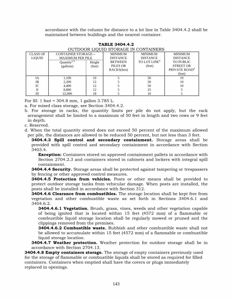
143
accordance with the column for distance to a lot line in Table 3404.4.2 shall be maintained between buildings and the nearest container.
TABLE 3404.4.2
OUTDOOR LIQUID STORAGE IN CONTAINERS CONTAINER STORAGE—
MAXIMUM PER PILE CLASS OF
LIQUID Quantitya, b
(gallons) Height (feet)
MINIMUM DISTANCE BETWEEN PILES OR
RACKS(feet)
MINIMUM DISTANCE
TO LOT LINEd (feet)
MINIMUM DISTANCE TO PUBLIC STREET OR
PRIVATE ROADd (feet)
IA IB IC II III
1,100 2,200 4,400 8,800
22,000
10 12 12 12 18
5 5 5 5 5
50 50 50 25 10
10 10 10 5 5
For SI: 1 foot = 304.8 mm, 1 gallon 3.785 L. a. For mixed class storage, see Section 3404.4.2. b. For storage in racks, the quantity limits per pile do not apply, but the rack
arrangement shall be limited to a maximum of 50 feet in length and two rows or 9 feet in depth.
c. Reserved. d. When the total quantity stored does not exceed 50 percent of the maximum allowed
per pile, the distances are allowed to be reduced 50 percent, but not less than 3 feet. 3404.4.3 Spill control and secondary containment. Storage areas shall be provided with spill control and secondary containment in accordance with Section 3403.4.
Exception: Containers stored on approved containment pallets in accordance with Section 2704.2.3 and containers stored in cabinets and lockers with integral spill containment.
3404.4.4 Security. Storage areas shall be protected against tampering or trespassers by fencing or other approved control measures. 3404.4.5 Protection from vehicles. Posts or other means shall be provided to protect outdoor storage tanks from vehicular damage. When posts are installed, the posts shall be installed in accordance with Section 312. 3404.4.6 Clearance from combustibles. The storage location shall be kept free from vegetation and other combustible waste as set forth in Sections 3404.6.1 and 3404.6.2.
3404.4.6.1 Vegetation. Brush, grass, vines, weeds and other vegetation capable of being ignited that is located within 15 feet (4572 mm) of a flammable or combustible liquid storage location shall be regularly mowed or pruned and the clippings removed from the premises. 3404.4.6.2 Combustible waste. Rubbish and other combustible waste shall not be allowed to accumulate within 15 feet (4572 mm) of a flammable or combustible liquid storage location.
3404.4.7 Weather protection. Weather protection for outdoor storage shall be in accordance with Section 2704.13.
3404.4.8 Empty containers storage. The storage of empty containers previously used for the storage of flammable or combustible liquids shall be stored as required for filled containers. Containers when emptied shall have the covers or plugs immediately replaced in openings.

144
FC 3406 Special Operations
3406.1 Scope. Flammable and combustible liquids shall be stored, handled and used in connection with special operations, including the following operations, in compliance with the requirements of this section:
1. Storage and dispensing of flammable and combustible liquids at construction sites. 2. Bulk plants or terminals 3. Bulk transfer and process transfer operations utilizing cargo tanks and tank cars. 4. Cargo tanks and cargo tank operation. 5. Vapor recovery and vapor-processing systems. 3406.1.1 General. Special operations involving the storage, handling and use of flammable and combustible liquids shall be conducted in accordance with Sections 3401, 3403, 3404 and 3405, except as otherwise provided in this section.
3406.2 Storage and dispensing of flammable and combustible liquids at construction sites. Temporary storage and dispensing of flammable and combustible liquids at construction sites shall be in accordance with Sections 3406.2.1 through 3406.2.8.
Exception: Storage and use of fuel oil connected with nonportable oil-burning equipment regulated by the Mechanical Code. 3406.2.1 Combustibles and open flames near tanks. Storage areas shall be kept free from weeds and other combustible waste. It shall be unlawful to smoke, or light or maintain an open flame in a flammable or combustible liquid storage area. 3406.2.2 Marking of tanks and containers. Tanks and containers for aboveground storage of liquids shall be conspicuously marked with the name of the product which they contain and the words: FLAMMABLE—KEEP FIRE AND FLAME AWAY. Tanks shall bear the additional marking: KEEP 50 FEET FROM BUILDINGS. 3406.2.3 Containers for storage and use. Flammable and combustible liquid shall only be stored in metal containers of a type meeting the requirements of the regulations of the United States Department of Transportation, as set forth in 49 CFR Part 178, or in containers of an approved design.
3406.2.3.1 Liquid handling devices. Discharge devices shall be of a type that do not develop an internal pressure on the container. Pumping devices or approved self-closing faucets used for dispensing liquids shall not leak and shall be well-maintained. Individual containers shall not be interconnected and shall be kept closed when not in use. 3406.2.3.2 Outdoor storage. Containers stored outdoors shall be in accordance with Section 3404 and the construction codes, including the Building Code.
3406.2.4 Temporary tanks. The capacity of temporary aboveground tanks containing flammable or combustible liquids shall not exceed 660 gallons (2498 L). Tanks shall be of the single-compartment design, shall be constructed of steel, and shall meet the requirements of the New York State Department of Environmental Conservation regulations, as set forth in 6 NYCRR Parts 613 and 614.
3406.2.4.1 Fill-opening security. Fill openings shall be equipped with a locking closure device. Fill openings shall be separate from vent openings. 3406.2.4.2 Vents. Tanks shall be provided with a method of normal and emergency venting. Normal vents shall also be in accordance with Section 3404.2.7.3. Emergency vents shall be in accordance with Section 3404.2.7.4. Emergency vents shall be arranged to discharge in a manner which prevents localized overheating or flame impingement on any part of the tank in the event that vapors from such vents are ignited.

145
3406.2.4.3 Location. Tanks containing flammable or combustible liquids shall be kept outdoors and at least 50 feet (15 240 mm) from buildings, combustible material and combustible waste. Additional distance shall be provided when necessary to ensure that vehicles, equipment and containers being filled directly from such tanks will not be less than 50 feet (15 240 mm) from structures or combustible storage.
3406.2.5 Type of tank. Tanks shall be provided with top openings only. Exception: Aerial crane refueling operations when conducted in accordance with Section 3406.2.5.2. 3406.2.5.1 Tanks with top openings only. Tanks with top openings shall be mounted as follows:
1. On well-constructed metal legs connected to shoes or runners designed so that the tank is stabilized and the entire tank and its supports can be moved as a unit; or
2. For stationary tanks, on a stable base of timbers or blocks approximately 6 inches (152 mm) in height which prevents the tank from contacting the ground.
3406.2.5.1.1 Pumps and fittings. Tanks with top openings only shall be equipped with a tightly and permanently attached, approved pumping device having an approved hose of sufficient length for filling construction equipment or containers to be served from the tank. Either the pump or the hose shall be equipped with a padlock to its hanger to prevent tampering. An antisiphoning device shall be provided in the pump discharge unless a self-closing nozzle is used. Siphons or internal pressure discharge devices shall not be used. 3406.2.5.2 Tanks for gravity discharge. Tanks with a connection in the bottom or the end for gravity-dispensing liquids for aerial crane refueling operations shall be mounted and equipped as follows: 1. Support lugs used to elevate the tank for gravity discharge shall be designed
to carry all required loads and provide stability. 2. Bottom or end openings for gravity discharge shall be equipped with a valve
located adjacent to the tank shell which will close automatically in the event of fire through the operation of a heat-activated releasing device. Where this valve cannot be operated manually, it shall be supplemented by a second, manually operated valve.
3. The gravity discharge outlet shall be provided with an approved hose equipped with a self-closing valve at the discharge end of a type that can be padlocked to its hanger.
3406.2.6 Spill control drainage control and diking. Indoor storage and dispensing areas shall be provided with spill control and drainage control as set forth in Section 3403.4. Outdoor storage areas shall be provided with drainage control or diking as set forth in Section 3404.2.10. 3406.2.7 Portable fire extinguishers. Portable fire extinguishers with a minimum rating of 20-B:C and complying with the requirements of Section 906 shall be provided where required by this code. 3406.2.8 Dispensing from cargo tanks. Where approved, liquids used as fuels are allowed to be transferred from cargo tanks into the fuel tanks of construction equipment at a construction site, subject to the following requirements:
1. The cargo tank is used solely for the purpose of supplying fuel to construction equipment at a construction site.
2. The dispensing hose does not exceed 100 feet (30 480 mm) in length.
146
3. The dispensing nozzle is an approved type. 4. The dispensing hose is properly placed on the approved reel or in a
compartment provided before the cargo tank is moved. 5. Signs prohibiting smoking and open flames within 25 feet (7620 mm) of the
cargo tank and construction equipment being refueled are prominently posted on the cargo tank.
6. Electrical devices and wiring in areas where fuel dispensing is conducted are in accordance with the Electrical Code.
7. Cargo tank-dispensing equipment is operated only by a person holding a certificate of fitness.
8. Provision has been made to control and mitigate the accidental or unauthorized release of flammable and combustible liquid.
9. The cargo tank has a capacity of not more than 1,920 gallons (7267 L), and contains no Class IA liquid and not more than 640 gallons (2422 L) of any other Class I liquid.
10. Dispensing is conducted at least 50 feet (15 240 mm) from buildings, structures, combustible material or combustible waste.
3406.3 Reserved. 3406.4 Bulk plants and terminals. Any premises in or upon which flammable and combustible liquids are received by marine vessels, pipelines, tank cars or cargo tanks and which are stored or blended in bulk for the purpose of distributing such liquids by marine vessels, pipelines, tanks cars, cargo tanks or containers shall be designed, installed, operated and maintained in accordance with Sections 3406.4.1 through 3406.4.10.4.
3406.4.1 Building construction. Buildings and structures shall be constructed in accordance with the construction codes, including the Building Code.
3406.4.1.1 Design and installation documents. A complete set of design and installation documents, including a site plan of the bulk plant or terminal shall be filed with the department.
3406.4.2 Means of egress. Rooms in which flammable and combustible liquids are stored, handled or used shall be arranged such that occupants engaging in such handling and use have readily available access to a means of egress in the event of fire. 3406.4.3 Heating. Rooms in which Class I liquids are stored, handled or used shall be heated only by means not constituting a source of ignition, such as steam or hot water. 3406.4.4 Ventilation. Ventilation shall be provided for rooms, enclosures and other areas in buildings or structures in which Class I liquids are handled or used, including any pumping or transfer. Ventilation systems shall be designed in a manner that takes into consideration the relatively high specific gravity of the vapors. When natural ventilation is approved, adequate openings in outside walls at floor level, unobstructed except by louvers or coarse screens, shall be provided. When natural ventilation is not approved, mechanical ventilation shall be provided in accordance with the construction codes, including the Mechanical Code.
3406.4.4.1 Basements and other areas below grade. Class I liquids shall not be stored, handled or used within a building or structure having a basement, cellar or other area below grade into which flammable vapors can travel, unless such area is provided with ventilation designed to prevent the accumulation of flammable vapors therein.

147
3406.4.4.2 Dispensing of Class I liquids. Containers of Class I liquids shall not be drawn from or filled indoors unless a provision is made to prevent the accumulation of flammable vapors in hazardous concentrations. Where mechanical ventilation is required, it shall be kept in operation while flammable vapors could be present.
3406.4.5 Storage. Except as otherwise provided in Section 3406.4, storage of flammable and combustible liquids in bulk plants and terminals shall be in compliance with the applicable requirements of Section 3404.
3406.4.5.1 Distance to lot line. The distance between any part of an aboveground flammable or combustible liquid storage tank and the nearest lot line shall be as provided in Table 3406.4.5.1, except where Sections 3406.4.5.1.1 through 3406.4.5.1.4 require a greater distance.
TABLE 3406.4.5.1 DISTANCE BETWEEN AN ABOVEGROUND STORAGE TANK AND LOT LINES
TANK CAPACITY MINIMUM DISTANCE (FEET)
≤30,000 gallons 20 Over 30,000 to 50,000 gallons 30
Over 50,000 to 100,000 50 Over 100,000 to 500,000 80
Over 500,000 to 1,000,000 100 Over 1,000,000 to 2,000,000 135 Over 2,000,000 to 3,000,000 165 Over 3,000,000 to 6,000,000 175
3406.4.5.1.1 Vertical cylindrical tanks over 50,000 gallons (189 250 L) storing a flammable liquid. For vertical cylindrical tanks over 50,000 gallons (189 250 L) storing a flammable liquid, the distance shall not be less than the greater dimension of height or diameter of the tank, up to a maximum distance of 175 feet (53 340 mm). 3406.4.5.1.2 Rectangular tanks over 50,000 gallons (189 250 L) storing a flammable liquid. For rectangular tanks over 50,000 gallons (189 250 L) storing a flammable liquid, the distance shall not be less than the total of the length and the width of the tank divided by two, up to a maximum distance of 175 feet (53 340 mm). 3406.4.5.1.3 Vertical cylindrical tanks over 50,000 gallons (189 250 L) storing a combustible liquid. For vertical cylindrical tanks over 50,000 gallons (189 250 L) storing a combustible liquid, the distance shall not be less than 1/2 the greater dimension of height or diameter of tank, up to a maximum distance of 175 feet (53 340 mm). 3406.4.5.1.4 Rectangular tanks over 50,000 gallons (189 250 L) storing a combustible liquid. For rectangular tanks over 50,000 gallons (189 250 L) storing a combustible liquid, the distance shall not be less than the total of the length and the width of the tank divided by 4, up to a maximum distance of 175 feet (53 340 mm).
3406.4.5.2 Distance between aboveground tanks. The distance between any part of an aboveground storage tank and adjacent tanks shall be in accordance with Table 3406.4.5.2.
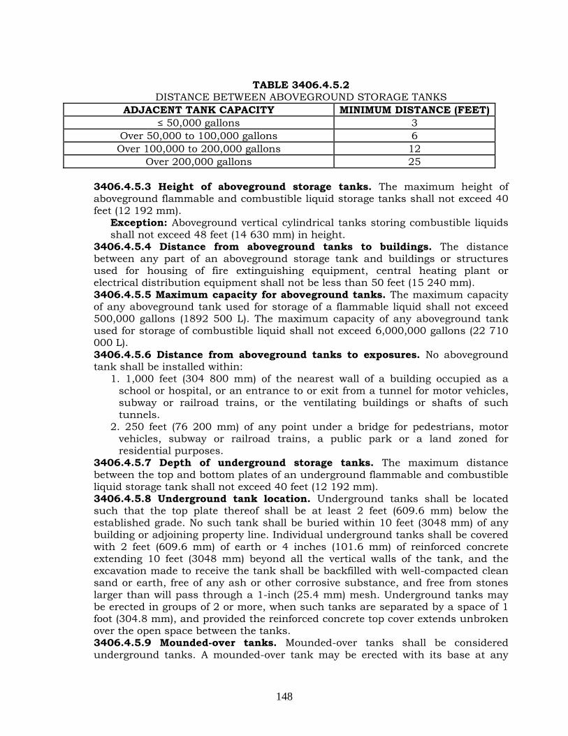
148
TABLE 3406.4.5.2
DISTANCE BETWEEN ABOVEGROUND STORAGE TANKS ADJACENT TANK CAPACITY MINIMUM DISTANCE (FEET)
≤ 50,000 gallons 3 Over 50,000 to 100,000 gallons 6 Over 100,000 to 200,000 gallons 12
Over 200,000 gallons 25 3406.4.5.3 Height of aboveground storage tanks. The maximum height of aboveground flammable and combustible liquid storage tanks shall not exceed 40 feet (12 192 mm).
Exception: Aboveground vertical cylindrical tanks storing combustible liquids shall not exceed 48 feet (14 630 mm) in height.
3406.4.5.4 Distance from aboveground tanks to buildings. The distance between any part of an aboveground storage tank and buildings or structures used for housing of fire extinguishing equipment, central heating plant or electrical distribution equipment shall not be less than 50 feet (15 240 mm). 3406.4.5.5 Maximum capacity for aboveground tanks. The maximum capacity of any aboveground tank used for storage of a flammable liquid shall not exceed 500,000 gallons (1892 500 L). The maximum capacity of any aboveground tank used for storage of combustible liquid shall not exceed 6,000,000 gallons (22 710 000 L). 3406.4.5.6 Distance from aboveground tanks to exposures. No aboveground tank shall be installed within:
1. 1,000 feet (304 800 mm) of the nearest wall of a building occupied as a school or hospital, or an entrance to or exit from a tunnel for motor vehicles, subway or railroad trains, or the ventilating buildings or shafts of such tunnels.
2. 250 feet (76 200 mm) of any point under a bridge for pedestrians, motor vehicles, subway or railroad trains, a public park or a land zoned for residential purposes.
3406.4.5.7 Depth of underground storage tanks. The maximum distance between the top and bottom plates of an underground flammable and combustible liquid storage tank shall not exceed 40 feet (12 192 mm). 3406.4.5.8 Underground tank location. Underground tanks shall be located such that the top plate thereof shall be at least 2 feet (609.6 mm) below the established grade. No such tank shall be buried within 10 feet (3048 mm) of any building or adjoining property line. Individual underground tanks shall be covered with 2 feet (609.6 mm) of earth or 4 inches (101.6 mm) of reinforced concrete extending 10 feet (3048 mm) beyond all the vertical walls of the tank, and the excavation made to receive the tank shall be backfilled with well-compacted clean sand or earth, free of any ash or other corrosive substance, and free from stones larger than will pass through a 1-inch (25.4 mm) mesh. Underground tanks may be erected in groups of 2 or more, when such tanks are separated by a space of 1 foot (304.8 mm), and provided the reinforced concrete top cover extends unbroken over the open space between the tanks. 3406.4.5.9 Mounded-over tanks. Mounded-over tanks shall be considered underground tanks. A mounded-over tank may be erected with its base at any

149
desired elevation not higher than the grade plane of the premises. It shall be enclosed with a steel, reinforced-concrete, or closed-face-concrete cribbing wall extending from the established grade to the top of the top cover, with the exterior face of the wall at least 10 feet (3048 mm) from the exterior face of the wall of the tank, and backfilled between the tank and the enclosing wall with compacted clean earth or sand containing no ash or other corrosive substance. The wall and backfill may be replaced with compacted similar fill, extending from the established grade to the level of the top cover on the tank, at the normal angle of repose of the material so used, with the provision that the width of the sloped material at the level of the top of the top cover shall be at least 10 feet (3048 mm) wide. When two or more mounded-over tanks, either rectangular or vertical-cylindrical, are grouped together, the tanks shall be at least 1 foot (304.8 mm) apart from each other, and the group of tanks shall be enclosed around the periphery with the same type of wall and backfill described above for one mounded-over tank. 3406.4.5.10 Maximum capacity of flammable liquid underground tanks. Underground storage tanks used for storage of a flammable liquid shall not exceed 500,000 gallons (1892 500 L), except that the commissioner may approve the installation of underground tanks with a capacity not to exceed 6,000,000 gallons (22 710 000L) where such greater capacity is determined to be necessary because of the capacity of the marine vessel, pipeline or tank car delivering such liquid and where such increased capacity does not endanger the public safety. 3406.4.5.11 Maximum capacity of combustible liquid underground tanks. Underground storage tanks used for storage of a combustible liquid shall not exceed 6,000,000 gallons (22 710 000 L). Such tanks may be compartmented; however, in no case shall any compartment exceed 4,000,000 gallons (15 140 000 L).
3406.4.6 Overfill protection. To prevent an overfill during the transfer of flammable or combustible liquid from a marine vessel, pipeline, tank car, cargo tank or storage tank, each tank shall be equipped with an approved electrically operated overfill protection system. Such system shall be in accordance with API 2350.
3406.4.6.1 Alarms. Audible and visible alarms shall be activated automatically when the liquid level in the tank approaches 95 percent of tank capacity and again when it attains a level of 98 percent of tank capacity. This alarm shall be connected to both the marine vessel, pipeline, tank car or cargo tank receiving point, as applicable, and to the facilty dispatcher's office. 3406.4.6.2 Tanks filled from pipelines. Tanks filled by pipeline shall be provided with a shutoff valve in the fill line that will automatically shut off the flow to the tank when the liquid level in the tank approaches 95 percent. 3406.4.7 Wharves. This section shall apply to all wharves, piers, bulkheads and other structures over or contiguous to navigable water having a primary function of transferring liquid cargo in bulk between shore installations and marine vessels, including barges, lighter boats or similar watercraft. Exception: Marine liquid motor fuel-dispensing facilities designed, installed, operated and maintained in accordance with Chapter 22. 3406.4.7.1 Transferring approvals. Handling packaged cargo of liquids, including full and empty drums, bulk fuel and stores, over a wharf during cargo transfer shall be subject to the approval and under the personal supervision of the bulk plant or terminal certificate of fitness holder and the senior deck officer on duty.

150
3406.4.7.2 Transferring location. Wharves at which liquid cargoes are to be transferred in bulk quantities to or from marine vessels shall be at least 100 feet (30 480 mm) from any bridge over a navigable waterway; or from any entrance to, or superstructure of, any vehicular or railroad tunnel under a waterway. The termination of the fixed piping used for loading or unloading at a wharf shall be at least 200 feet (60 960 mm) from a bridge or from an entrance to, or superstructures of, a tunnel. 3406.4.7.3 Superstructure and decking material. Superstructure and decking shall be designed for the intended use. Decking shall be constructed of materials that will afford the desired combination of flexibility, resistance to shock, durability, strength and fire resistance. 3406.4.7.4 Wharf tanks prohibited. It shall be unlawful to install, operate or maintain on wharfs any tanks containing flammable and combustible liquids. 3406.4.7.5 Transferring equipment. Loading pumps capable of building up pressures in excess of the safe working pressure of cargo hose or loading arms shall be provided with bypasses, relief valves or other arrangements to protect the loading facilities against excessive pressure. Relief devices shall be tested at least annually to determine that they function satisfactorily at their set pressure. 3406.4.7.6 Piping, valves, fittings and ancillary equipment. Piping systems shall be in accordance with Section 3403.6 except as otherwise provided as follows:
1. Piping systems shall be designed to protect against physical damage resulting from the motion of the wharf from wave action, currents, tides or the mooring of marine vessels.
2. Pipe joints that depend on the friction characteristics of combustible materials or on the grooving of pipe ends for mechanical continuity of piping shall not be used.
3. Swivel joints may be used in piping to which hoses are connected and for articulated, swivel-joint transfer systems, provided that the design of the swivel joints is such that the mechanical strength of the joint will not be impaired if the packing materials fail such as by exposure to fire.
4. Each pipe used to convey Class I or II liquids leading to a wharf shall be provided with a readily accessible block valve located on shore near the approach to the wharf and outside of any diked area. Where more than one line is used to convey liquid, the valves shall be grouped in one location.
5. Means shall be provided for ready access to cargo line valves located below the wharf deck.
6. Piping systems shall contain a sufficient number of valves to operate the system properly and to control the flow of liquid both during normal operation and in the event of physical damage.
7. Piping on wharves shall be bonded and grounded where Class I and II liquids are transported. If excessive stray current conditions exist, insulating joints shall be installed. Bonding and grounding connections on piping shall be located on the wharf side of hose riser insulating flanges, where used, and shall be accessible for inspection.
8. Hose or articulated swivel-joint pipe connections used for cargo transfer shall be capable of accommodating the combined effects of change in draft and maximum tidal range, and mooring lines shall be kept adjusted to prevent surge of the marine vessel from placing stress on the cargo transfer system.

151
9. Hoses shall be supported to avoid kinking and physical damage, including damage from chafing.
10. Piping, hoses, valves and fittings shall be constructed of steel. Valves shall be rated for not less than 150 pounds per square inch (psig)(1034 kPa).
3406.4.7.7 Loading and unloading. Loading or unloading shall not commence until the bulk plant or terminal certificate of fitness holder and officer in charge of the marine vessel agree that the marine vessel has been properly moored and connections have been properly made. 3406.4.7.8 Construction work. Construction work shall not be performed on the wharf except as approved by the commissioner upon a determination that such work can be safely performed, and subject to such terms and conditions as the commissioner may prescribe in the interest of public safety.
3406.4.8 Sources of ignition. Class I, II or IIIA liquids shall not be used, drawn or dispensed where flammable vapors can reach a source of ignition. 3406.4.9 Drainage control. Loading and unloading areas shall be provided with drainage control in accordance with Section 3404.2.10. 3406.4.10 Fire protection. Fire protection shall be in accordance with Chapter 9 and Sections 3406.4.10.1 through 3406.4.10.8.
3406.4.10.1 Portable fire extinguishers. Portable fire extinguishers with a rating of not less than 20-B and complying with the requirements of Section 906 shall be located within 75 feet (22 860 mm) of hose connections, pumps and separator tanks. 3406.4.10.2 Fire hoses. Fire hose connected to a water supply in a size appropriate for the water supply shall be provided in accordance with Section 905 and the construction codes, including the Building Code, so that manifolds where connections are made and broken can be reached by at least one hose stream. 3406.4.10.3 Obstruction of equipment. Material shall not be placed on wharves in such a manner that would obstruct access to firefighting apparatus or equipment or important pipeline or other delivery control valves. 3406.4.10.4 Fire apparatus access. An unobstructed fire apparatus access road to the shore end of the wharf shall be maintained in accordance with Chapter 5. 3406.4.10.5 Fire protection systems. Aboveground tanks, mounded-over tanks, underground tanks, tank car loading and unloading racks, cargo tank loading racks, cargo tank unloading areas, marine vessel loading and unloading areas and all other portions of a bulk plant or terminal shall be provided with fire extinguishing systems that are approved by the commissioner, inspected by a representative of the department and tested at the owner’s risk by his or her representative before a representative of the department. Such systems shall include an approved yard hydrant system and tank monitor nozzles.
3406.4.10.5.1 Cargo tank loading racks. A fire extinguishing system shall be provided over and under each cargo tank loading position. At least one remote control valve shall be provided to control the extinguishing agent for each three loading positions. Piping systems shall be installed so they can be thoroughly drained. The fire extinguishing system shall be sized to provide protection for the three largest adjacent loading positions.
3406.4.10.6 Emergency alarm transmission. Manual pull stations shall be provided at one or more approved locations that will automatically transmit a signal to the department via an approved central station. 3406.4.10.7 Periodic tests. Fire extinguishing systems, fire protection systems and tank overfill protection shall be tested once every 2 years at the owner’s risk

152
by his or her representative before a representative of the department. Tests of foam extinguishing systems shall produce foam at the most remote tank and produce water flow at each tank. In the event that the discharge of foam to the most remote tank would result in a reportable hazardous material release in accordance with federal, state or local laws, rules or regulations, such other test acceptable to the commissioner may be conducted. 3406.4.10.8 Color coding and labeling. Fire protection systems shall be color-coded and labeled in accordance with Sections 3406.4.10.8.1 through 3406.4.10.8.2. Copies of the color code shall be posted in all central locations for fire extinguishing media, such as the foam house location.
3406.4.10.8.1 Color coding. Fire protection systems shall be color-coded as follows:
1. Standpipe and/or yard hydrant systems: 1.1. Piping, valve bodies and handles, hydrants and hydrant or hose
houses: Red with contrasting white bands. 1.2. Department siamese connections: Red.
2. Sprinkler systems (wet or dry): 2.1. Piping and valve bodies and handles: Red with contrasting bright
green bands. 2.2. Department siamese connections: Red with green caps.
3. Non-automatic sprinkler systems (including fog spray systems): 3.1. Piping and valve bodies and handles: Red with contrasting
aluminum bands. 3.2. Department siamese connections: Aluminum.
4. Carbon dioxide extinguishing systems – piping, valve bodies and handles: Red with contrasting brown bands.
5. Steam extinguishing systems – piping, valve bodies and handles: Red with contrasting black bands.
6. Foam extinguishing systems: 6.1. Piping, valve bodies and handles, hydrants and hydrant or hose
houses: Red with contrasting bright orange bands. 6.2. Department water connections: Red. A durable sign that reads
“WATER FOR FOAM SYSTEM”, shall be conspicuously posted immediately adjacent to such connections.
6.3. Department foam connection: Red with contrasting bright orange band or caps. A durable sign that reads “CHEMICAL FOAM DIRECT TO TANKS” or “...% MECHANICAL FOAM SOLUTION DIRECT TO TANKS”, shall be conspicuously posted immediately adjacent to such connections.
3406.4.10.8.2 Labeling. Bands, or piping immediately adjacent to bands, shall be labeled to indicate the names of the extinguishing media. The letters shall be in a contrasting color of a suitable size in proportion to the pipe diameters. The width of each band shall be not less than the pipe diameter and shall be spaced not more than 30 feet (9144 mm) apart. Bands, lettering and piping shall be painted in sun- and weather-resistant colors and paint; but bands and lettering may be applied by means of pressure sensitive tape that is sun- and weather-resistant.
3406.4.11 Interconnected piping. All tanks shall be connected by a system of steel pipes in a manner that the contents of each tank may be transferred to another tank
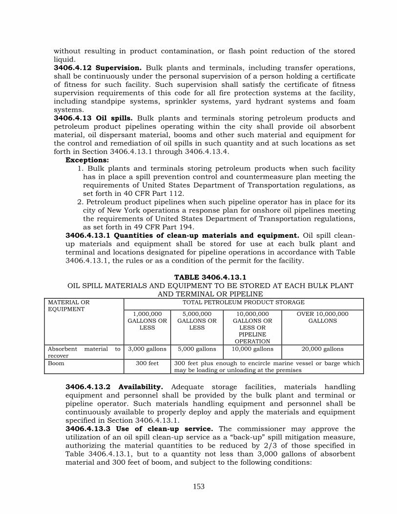
153
without resulting in product contamination, or flash point reduction of the stored liquid. 3406.4.12 Supervision. Bulk plants and terminals, including transfer operations, shall be continuously under the personal supervision of a person holding a certificate of fitness for such facility. Such supervision shall satisfy the certificate of fitness supervision requirements of this code for all fire protection systems at the facility, including standpipe systems, sprinkler systems, yard hydrant systems and foam systems. 3406.4.13 Oil spills. Bulk plants and terminals storing petroleum products and petroleum product pipelines operating within the city shall provide oil absorbent material, oil dispersant material, booms and other such material and equipment for the control and remediation of oil spills in such quantity and at such locations as set forth in Section 3406.4.13.1 through 3406.4.13.4.
Exceptions: 1. Bulk plants and terminals storing petroleum products when such facility
has in place a spill prevention control and countermeasure plan meeting the requirements of United States Department of Transportation regulations, as set forth in 40 CFR Part 112.
2. Petroleum product pipelines when such pipeline operator has in place for its city of New York operations a response plan for onshore oil pipelines meeting the requirements of United States Department of Transportation regulations, as set forth in 49 CFR Part 194.
3406.4.13.1 Quantities of clean-up materials and equipment. Oil spill clean-up materials and equipment shall be stored for use at each bulk plant and terminal and locations designated for pipeline operations in accordance with Table 3406.4.13.1, the rules or as a condition of the permit for the facility.
TABLE 3406.4.13.1 OIL SPILL MATERIALS AND EQUIPMENT TO BE STORED AT EACH BULK PLANT
AND TERMINAL OR PIPELINE TOTAL PETROLEUM PRODUCT STORAGE MATERIAL OR
EQUIPMENT 1,000,000
GALLONS OR LESS
5,000,000 GALLONS OR
LESS
10,000,000 GALLONS OR
LESS OR PIPELINE
OPERATION
OVER 10,000,000 GALLONS
Absorbent material to recover
3,000 gallons 5,000 gallons 10,000 gallons 20,000 gallons
Boom 300 feet 300 feet plus enough to encircle marine vessel or barge which may be loading or unloading at the premises
3406.4.13.2 Availability. Adequate storage facilities, materials handling equipment and personnel shall be provided by the bulk plant and terminal or pipeline operator. Such materials handling equipment and personnel shall be continuously available to properly deploy and apply the materials and equipment specified in Section 3406.4.13.1. 3406.4.13.3 Use of clean-up service. The commissioner may approve the utilization of an oil spill clean-up service as a “back-up” spill mitigation measure, authorizing the material quantities to be reduced by 2/3 of those specified in Table 3406.4.13.1, but to a quantity not less than 3,000 gallons of absorbent material and 300 feet of boom, and subject to the following conditions:

154
1. A responsible officer of the bulk plant and terminal or pipeline operation shall submit a sworn affidavit identifying the oil spill clean-up service with which it has contracted to perform such services, averring that such oil spill clean-up service meets the standards set forth in Section 3406.4.13.4 and setting forth the nature of the services to be rendered.
2. The department shall be notified, in writing, within 10 business days of the date when the utilization of the clean-up service is cancelled or the service goes out of business.
3. Such approval may be rescinded by the commissioner for good cause for failure of the spill clean-up service to timely respond to an oil spill, to have adequate equipment, materials or personnel, or to obey or cooperate with the department representatives in charge of the scene of the oil spill.
3406.4.13.4 Oil spill clean-up service standards. An oil spill clean-up service may be retained by a bulk plant, bulk terminal or pipeline operation pursuant to Section 3406.13.3 provided it is capable of meeting the following standards:
1. It maintains the stockpile of material and equipment required by Section 3406.4.13.1 for storage of over 10,000,000 gallons (37 850 000 L) of petroleum products, regardless of the amount of petroleum products actually stored at the contracting bulk plants, bulk terminals or pipelines.
2. A supervisor will respond to the spill site within 1 hour from time of notification.
3. It is capable of delivering, on a 24-hour, 7-day-a-week basis, sufficient materials, equipment and personnel to the contracting bulk plant, bulk terminal or pipeline within 2 hours from time of notification.
4. Such service is licensed and operated in accordance with all applicable federal, state and local laws.
3406.4.14 Valves. All inlet and outlet nozzles of tanks shall be provided with a valve of steel construction of a 150 pounds per square inch (psig)(1034 kPa) rating located as close as practicable to the tank. 3406.4.15 Dike construction. All dike walls shall be of steel or reinforced concrete, designed to be liquid tight and to withstand a full hydraulic head, and constructed so as to afford ready access. Where stairways or other similar means are required to afford such access, they shall be constructed of steel or other approved noncombustible material. 3406.4.16 Dike capacity. Each single dike wall enclosure shall have a capacity equal to 110 percent of the tank’s capacity. Tanks arranged in groups with a total capacity not exceeding 500,000 gallons (1892 500 L) may be enclosed in a single dike wall enclosure. Each group tank dike area shall have a net capacity not less than that of the largest tank plus 10 percent of the aggregate capacity of all other tanks served by the dike enclosure. That portion of the surface occupied by tank or tanks shall be included when computing the diked area. 3406.4.17 Tank and piping test. Tank and piping shall be tested at the time of installation at the owner’s risk by his or her representative before a representative of the department as follows:
1. Aboveground, underground and mounded-over tanks shall be filled to capacity with water and maintained for not less than 24 hours.
2. Piping shall be hydrostatically tested to a pressure of 100 pounds per square inch (psig)(689.5 kPa) or 150 percent of the maximum operating pressure, whichever is greater, for 30 minutes.
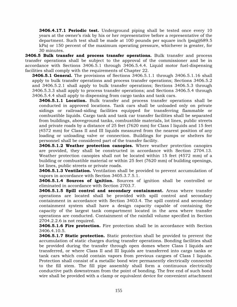
155
3406.4.17.1 Periodic test. Underground piping shall be tested once every 10 years at the owner’s risk by his or her representative before a representative of the department. Such test shall be made at 100 pounds per square inch (psig)(689.5 kPa) or 150 percent of the maximum operating pressure, whichever is greater, for 30 minutes.
3406.5 Bulk transfer and process transfer operations. Bulk transfer and process transfer operations shall be subject to the approval of the commissioner and be in accordance with Sections 3406.5.1 through 3406.5.4.4. Liquid motor fuel-dispensing facilities shall comply with the requirements of Chapter 22.
3406.5.1 General. The provisions of Sections 3406.5.1.1 through 3406.5.1.16 shall apply to bulk transfer operations and process transfer operations; Sections 3406.5.2 and 3406.5.2.1 shall apply to bulk transfer operations; Sections 3406.5.3 through 3406.5.3.3 shall apply to process transfer operations; and Sections 3406.5.4 through 3406.5.4.4 shall apply to dispensing from cargo tanks and tank cars.
3406.5.1.1 Location. Bulk transfer and process transfer operations shall be conducted in approved locations. Tank cars shall be unloaded only on private sidings or railroad-siding facilities equipped for transferring flammable or combustible liquids. Cargo tank and tank car transfer facilities shall be separated from buildings, aboveground tanks, combustible materials, lot lines, public streets and private roads by a distance of 25 feet (7620 mm) for Class I liquids and 15 feet (4572 mm) for Class II and III liquids measured from the nearest position of any loading or unloading valve or connection. Buildings for pumps or shelters for personnel shall be considered part of the transfer facility. 3406.5.1.2 Weather protection canopies. Where weather protection canopies are provided, they shall be constructed in accordance with Section 2704.13. Weather protection canopies shall not be located within 15 feet (4572 mm) of a building or combustible material or within 25 feet (7620 mm) of building openings, lot lines, public streets or private roads. 3406.5.1.3 Ventilation. Ventilation shall be provided to prevent accumulation of vapors in accordance with Section 3405.3.7.5.1. 3406.5.1.4 Sources of ignition. Sources of ignition shall be controlled or eliminated in accordance with Section 2703.7. 3406.5.1.5 Spill control and secondary containment. Areas where transfer operations are located shall be provided with spill control and secondary containment in accordance with Section 3403.4. The spill control and secondary containment system shall have a design capacity capable of containing the capacity of the largest tank compartment located in the area where transfer operations are conducted. Containment of the rainfall volume specified in Section 2704.2.2.6 is not required. 3406.5.1.6 Fire protection. Fire protection shall be in accordance with Section 3406.4.10.5. 3406.5.1.7 Static protection. Static protection shall be provided to prevent the accumulation of static charges during transfer operations. Bonding facilities shall be provided during the transfer through open domes where Class I liquids are transferred, or where Class II and III liquids are transferred into cargo tanks or tank cars which could contain vapors from previous cargoes of Class I liquids. Protection shall consist of a metallic bond wire permanently electrically connected to the fill stem. The fill pipe assembly shall form a continuous electrically conductive path downstream from the point of bonding. The free end of such bond wire shall be provided with a clamp or equivalent device for convenient attachment

156
to a metallic part in electrical contact with the cargo tank or tank car. For cargo tanks, protection shall consist of a flexible bond wire of adequate strength for the intended service and the electrical resistance shall not exceed 1 megohm. For tank cars, bonding shall be provided where the resistance of a tank car to ground through the rails is 25 ohms or greater. Such bonding connection shall be fastened to the cargo tank or tank car before dome covers are raised and shall remain in place until filling is complete and all dome covers have been closed and secured.
Exceptions: 1. Where cargo tanks or tank cars are loaded exclusively with products not
having a static-accumulating tendency, such as asphalt, cutback asphalt, most crude oils, residual oils and water-miscible liquids.
2. When Class I liquids are not handled at the transfer facility and the cargo tanks are used exclusively for Class II and III liquids.
3. Where cargo tanks or tank cars are loaded or unloaded through closed top or bottom connections when the hose is conductive.
3406.5.1.7.1 Filling through open domes. Filling through open domes into the tanks of cargo tanks or tank cars that contain vapor-air mixtures within the flammable range, or where the liquid being filled can form such a mixture, shall be by means of a downspout which extends to near the bottom of the tank. It shall be unlawful to fill a cargo tank or tank car with gasoline through an open dome.
3406.5.1.8 Stray current protection. Tank car loading facilities where Class I, II or IIIA liquids are transferred through open domes shall be protected against stray currents by permanently bonding the pipe to at least one rail and to the transfer apparatus. Multiple pipes entering the transfer areas shall be permanently electrically bonded together. In areas where excessive stray currents are known to exist, all pipes entering the transfer area shall be provided with insulating sections to isolate electrically the transfer apparatus from the pipelines. 3406.5.1.9 Top loading. When top loading a cargo tank with Class I and II liquids without vapor control, valves used for the final control of flow shall be of the self-closing type and shall be manually held open except where automatic means are provided for shutting off the flow when the tank is full. When used, automatic shutoff systems shall be provided with a manual shutoff valve located at a safe distance from the loading nozzle to stop the flow if the automatic system fails. When top loading a cargo tank with vapor control, flow control shall be in accordance with Section 3406.5.1.10. Self-closing valves shall not be tied or locked in the open position. 3406.5.1.10 Bottom loading. When bottom loading a cargo tank or tank car with or without vapor control, a positive means shall be provided for loading a predetermined quantity of liquid, together with an automatic secondary shutoff control to prevent overfill. The connecting components between the transfer equipment and the cargo tank or tank car required to operate the secondary control shall be functionally compatible.
3406.5.1.10.1 Dry disconnect coupling. When bottom loading a cargo tank, the coupling between the liquid loading hose or pipe and the cargo tank piping shall be a dry disconnect coupling. 3406.5.1.10.2 Venting. When bottom loading a cargo tank or tank car that is equipped for vapor control and vapor control is not required or used for the product being loaded, the tank shall be vented to the atmosphere to prevent

157
pressurization of the tank. Such venting shall be at a height equal to or greater than the top of the cargo tank or tank car. 3406.5.1.10.3 Vapor-tight connection. Connections to the plant vapor control system shall be designed to prevent the escape of vapor to the atmosphere when not connected to a cargo tank or tank car. 3406.5.1.10.4 Vapor recovery and processing equipment. Vapor recovery and processing equipment at bulk plants and terminals shall comply with the requirements of Section 3406.8.
3406.5.1.11 Switch loading. Cargo tanks or tank cars which have previously contained Class I liquids shall not be loaded with Class II or III liquids until such tanks or cars and all piping, pumps, hoses and meters connected thereto have been completely drained and flushed. 3406.5.1.12 Loading racks. Where provided, loading racks, stairs or platforms shall be constructed of noncombustible materials. Buildings for pumps or for shelter of loading personnel are allowed to be part of the loading rack. Wiring and electrical equipment located within 25 feet (7620 mm) of any portion of the loading rack shall be in accordance with Section 3403.1.1. 3406.5.1.13 Transfer apparatus. Bulk and process transfer apparatus shall be of an approved type. 3406.5.1.14 Inside buildings. Cargo tanks and tank cars shall not be located indoors while transferring Class I, II or III liquids.
Exception: Cargo tanks are allowed under weather protection canopies and canopies of automotive liquid motor fuel-dispensing facilities.
3406.5.1.15 Cargo tank and tank car certification. Certification shall be maintained for cargo tanks and tank cars in accordance with the regulations of the United States Department of Transportation, as set forth in Parts 100-178.
3406.5.1.15.1 Loading and unloading from cargo tanks. It shall be unlawful for any person to load a cargo tank with any flammable or Class II or IIIA combustible liquid or to receive or accept delivery of such products in or from a cargo tank, except in or from a cargo tank for which a department permit has been issued and is displayed pursuant to the provisions of Chapter 27. The provisions of this section shall not prohibit the loading of a cargo tank with any liquid products with a flash point over 200°F (93°C) nor the receiving or acceptance of delivery from a cargo tank of any liquid products with a flash point over 200°F (93°C), provided that such cargo tank is designed, constructed, and equipped in accordance with the regulations of the United States Department of Transportation governing the transportation of dangerous articles by common, contract, private and proprietary carriers engaged in interstate commerce.
3406.5.1.16 Cargo tank and tank car stability. Cargo tanks and tank cars shall be stabilized against movement during loading and unloading in accordance with Sections 3406.5.1.16.1 through 3406.5.1.16.3.
3406.5.1.16.1 Cargo tanks. When a cargo tank is parked for loading or unloading, such cargo tank shall be secured in a manner that will prevent unintentional movement. 3406.5.1.16.2 Chock blocks. At least two chock blocks not less than 5 inches by 5 inches by 12 inches (127 mm by 127 mm by 305 mm) in size and dished to fit the contour of the tires shall be used during transfer operations of cargo tanks.

158
3406.5.1.16.3 Tank cars. Brakes shall be set and the wheels shall be blocked to prevent rolling.
3406.5.2 Bulk transfer. Bulk transfer shall be in accordance with Sections 3406.5.1 and 3406.5.2.1.
3406.5.2.1 Vehicle motor. Motors of cargo tanks or tank cars shall be shut off during the making and breaking of hose connections and during the unloading operation.
Exception: Where unloading is performed with a pump deriving its power from the cargo tank motor.
3406.5.3 Process transfer. Process transfer shall be in accordance with Section 3406.5.1 and Sections 3406.5.3.1 through 3406.5.3.3.
3406.5.3.1 Piping, valves, hoses and fittings. Piping, valves, hoses and fittings which are not a part of the cargo tank or tank car shall be designed and installed in accordance with Section 3403.6. Caps or plugs which prevent leakage or spillage shall be provided at all points of connection to transfer piping.
3406.5.3.1.1 Shutoff valves. Approved automatically or manually activated shutoff valves shall be provided where the transfer hose connects to the process piping, and on both sides of any exterior fire-resistance-rated wall through which the piping passes. Manual shutoff valves shall be arranged such that they are readily accessible from grade. Valves shall not be locked in the open position. 3406.5.3.1.2 Hydrostatic relief. Hydrostatic pressure-limiting or relief devices shall be provided where pressure buildup in trapped sections of the system could exceed the design pressure of the components of the system. Devices shall relieve to other portions of the system or to another approved location. 3406.5.3.1.3 Antisiphon valves. Antisiphon valves shall be provided when the system design would allow siphonage.
3406.5.3.2 Vents. Normal and emergency vents shall be maintained in good working order at all times. 3406.5.3.3 Motive power. Motors of cargo tanks and tank cars shall be shut off during the making and breaking of hose connections and during the unloading operation.
Exception: When unloading is performed with a pump deriving its power from the cargo tank motor.
3406.5.4 Dispensing from cargo tanks and tank cars. It shall be unlawful to dispense any flammable or combustible liquid from a cargo tank or tank car into the fuel tanks of motor vehicles, except as authorized by and conducted in accordance with Sections 3406.5.4.3 and 3406.5.4.4.
3406.5.4.1 Reserved. 3406.5.4.2 Reserved. 3406.5.4.3 Aircraft fueling. Transfer of liquids from aircraft-refueling vehicles to the fuel tanks of aircraft shall be in accordance with Chapter 11. 3406.5.4.4 Fueling of vehicles at construction sites. The transfer of liquid from cargo tanks to construction equipment at construction sites shall be conducted in accordance with Section 3406.2.8.
3406.6 Reserved. 3406.7 Reserved. 3406.8 Vapor recovery and processing systems for use in bulk plants and terminals. Vapor recovery and processing systems installed at bulk plants and

159
terminals, including systems associated with piping, loading racks, dikes, fire detection and fire protection equipment, shall be designed, installed, operated and maintained in accordance with Sections 3406.8.1 through 3406.8.3. Such compliance shall be required for all vapor recovery processing systems, whether installed voluntarily or pursuant to the requirements of the United States Environmental Protection Agency, United States Coast Guard or New York State Department of Environmental Conservation.
3406.8.1 General. Vapor recovery and processing systems shall comply with the requirements of Section 5.10 of NFPA 30, except as otherwise provided in this section, the regulations of the United States Environmental Protection Agency, United States Coast Guard and New York State Department of Environmental Conservation, as applicable, and the following general requirements: 1. Electrical equipment shall comply with the requirements of the Electrical Code.
Upon request, proof of compliance with the Electrical Code shall be filed with the department.
2. The installation of any refrigerating system shall comply with the requirements of Chapter 6 and the Mechanical Code.
3. All tanks and piping shall be grounded. Static bonding connections shall be made between loading arm, vehicle and vapor recovery unit. An interlock shall be provided to prevent pumping operations until properly grounded.
4. All product pumps and compressors shall be of a type approved for such use. 5. Pressure vessels shall conform to the ASME Boiler and Pressure Vessel Code. The
manufacturer data sheet for the pressure vessel shall be maintained on the premises and made available for inspection to any representative of the department.
6. Knock-out vessels shall be provided with a high liquid level sensor that will initiate shutdown of the liquid transfer into the vessel and the vapor recovery or processing system.
7. A flame arrestor and mist eliminator element shall be provided at final emission vent.
8. A fire detection system shall be provided that will initiate shutdown of the vapor recovery and processing system in the event of fire.
9. An annunciator panel with audible and visible alarms shall be provided in the dispatcher's office. The annunciator panel shall monitor and shut down the vapor recovery and processing system upon any equipment malfunction, including a malfunction of the fire detection system.
10. Insulation material shall be noncombustible. 11. Lightning protection shall be provided in accordance with NFPA 780. 12. Pressure relief valves shall be provided on all pressure vessels and wherever else
required by the system design, and shall be sized in accordance with the ASME Boiler and Pressure Vessel Code. Pressure relief valves shall discharge to a safe location. No shutoff valve may be permitted in the line of relief. Tanks and equipment shall have independent venting for over-pressure or vacuum conditions that might occur from malfunction of the vapor recovery or recovery unit.
13. A reinforced concrete base shall be provided and approved by the agency having jurisdiction.
14. Vapor recovery and processing systems shall be placed in an unpierced dike of such construction and capacity as the commissioner may prescribe. No drains shall be permitted, and any drain pump used shall be manually activated.
15. Vapor recovery and processing systems shall be installed at least 25 feet (7620 mm) from bulk storage tanks, warehouses, loading racks, dispatchers' offices,

160
transfer facilities, buildings housing fire protection systems, central heating plants or electrical distribution systems, other plant buildings, building lines and adjoining lot lines. When vessels in the vapor recovery and processing system operate in excess of 50 pounds per square inch gauge (psig)(345 kPa), but less than 150 pounds per square inch gauge (psig)(1034 kPa), the minimum distance shall be 50 feet (15 240 mm), unless a protective structure, such as masonry or concrete fire wall, is installed in the line of sight between such vessel and the exposure, in which case the minimum distance of 25 feet (7620 mm) shall be applicable.
16. Vents on vapor-processing equipment shall be not less than 15 feet (4572 mm) from ground level, with outlets located and directed so that flammable vapors will disperse to below the lower flammable limit (LFL) before reaching a potential ignition source.
17. The vapor recovery and processing system shall be protected from physical damage, including damage by motor vehicles utilizing dikes, posts, or other approved means.
18. The entire vapor recovery and processing system shall be inspected for proper operation on a periodic basis, but not less than once every six months, by a qualified person. Such inspection shall be documented in a log book maintained at the facility for such purpose.
19. Durable signs reading “DANGER-NO SMOKING, MATCHES, OPEN LIGHTS OR SPARKING DEVICES AT THIS EQUIPMENT” shall be conspicuously posted at or near the vapor recovery and processing system in addition to the “No Smoking” signs required throughout the facility.
20. One or more foam hydrants, yard hydrants, monitor nozzles and portable fire extinguishers having a minimum 40-B:C rating, shall be provided within 50 feet (15 240 mm) of the vapor recovery and processing system and shall be readily available for use.
21. All piping associated with a vapor recovery and processing system, including piping connecting such system to storage tanks, shall be hydrostatically tested to a pressure of 100 pounds per square inch gauge (psig)(690 kPa) or 1½ times the maximum working pressure, whichever is greater, for a period of 2 hours, and shall show no leaks. Such hydrostatic testing shall be conducted at the owner’s risk by his or her representative before a representative of the department. In lieu of such hydrostatic testing, the commissioner may accept an affidavit from the manufacturer attesting to the integrity of piping integral to the vapor recovery and processing system.
22. Where a storage tank is connected to a vapor recovery and processing system, a mist eliminator shall be provided in the vapor line at or adjacent to the tank to remove entrained liquid and return same to the tank or an approved collection system.
23. The vapor recovery and processing system shall be designed to minimize and dissipate static electricity in accordance with NFPA 77.
3406.8.2 Atmospheric condensation and refrigeration vapor recovery and processing systems. A vapor condenser system shall be placed in an unpierced dike or within a concrete trench of adequate width and depth to hold at least 1 hour's vapor recovery. 3406.8.3 Absorption vapor recovery and processing systems. Absorption vapor recovery and processing systems shall comply with the following requirements: 7. A lean oil storage tank shall be protected by a foam fire extinguishing system.

161
8. The entire vapor recovery and processing system, including the lean oil storage tank, shall be placed in an unpierced dike. The height of the dike shall be based upon the size of the lean oil storage tank and shall have a capacity of at least 110% of such tank, but in any event not less than the maximum pumping capacity of the system for 20 minutes of operation.
9. Heaters used shall be of a type approved for such use and shall be equipped with an automatic shut-off device that activates upon reaching the high temperature limit for the absorption vapor recovery and processing system.
10. All absorbers, saturators, heat exchangers and condensers shall conform to ASME Boiler and Pressure Vessel Code and the provisions of Chapter 30.
11. A relief valve shall be provided for compressors, stripper columns and other pressure vessels.
12. Lean oil tanks and vapor vessels shall be constructed and installed in accordance with this chapter and API 650.
13. Upon installation, a vapor vessel bladder shall be pneumatically tested at 1¼ times the maximum operating pressure for 4 hours without leakage. A retest shall be performed annually. All such tests shall be conducted at the owner’s risk by his or her representative before a representative of the department.
3406.9 Cargo tank loading rack systems. Loading rack systems shall be designed, installed, operated and maintained in accordance with the following requirements:
1. Any vapor recovery and processing system used in connection with a loading rack system shall comply with the requirements of Sections 3406.8.1 through 3406.8.3.
2. Loading racks shall be protected throughout by a fire extinguishing system as set forth in Section 3406.4.10.5.1.
3. Cargo tanks loaded at bulk plants or terminals shall be compatible with all safety features incorporated into the loading rack.
4. Dry break adapters conforming to API standards shall be provided on the fill and vapor recovery lines. During loading, each cargo tank compartment shall be sealed except for the dry-break fill coupling and vapor recovery line.
5. An interlock shall be provided to prevent loading when the cargo tank vehicle motor is running and to prevent start up of the cargo tank vehicle motor during loading. Such interlock device shall further prevent the vehicle motor from starting before the product fill line and vapor return line have been disconnected.
6. An interlock device shall be provided so that no loading may take place unless the vapor recovery line is properly connected to the cargo tank.
7. Except when loading, protective caps shall cover all dry-break adapters as protection against the elements and physical damage from impact.
8. No more than 3 compartments may be loaded at a time. 9. A two-stage preset meter shall be provided for each loading arm. Loading arms
shall be equipped with manual or electronic dead-man control valves. 10. All electrical equipment shall be suitable for use in hazardous locations. The
design of the electronic sending device shall be such that a source of higher voltage or current cannot be connected to same.
11. An approved overfill prevention system shall be provided at the loading rack and shall be designed to ensure at least 1% vapor space per compartment. In no event shall the vapor space in a compartment be less than 40 gallons (151 L) in capacity.
12. A liquid detector shall be provided in the vapor return line, to automatically shut off the loading system if liquid reaches the vapor line.

162
13. All components of the fill and vapor recovery loading arm assemblies making contact with the cargo tank, including the loading head, shall be constructed of spark-proof material.
14. The fill line and the vapor recovery line in loading arm assemblies shall be of the same diameter. The maximum velocity in any liquid line shall not exceed 15 feet per second (4572 mm per second).
15. The fill line and vapor recovery line in loading arm assemblies shall be constructed of rigid steel, except that flexible hose may be used for fill or vapor recovery loading assemblies provided that such hose is no longer in length than necessary, has an inner diameter no greater than 4 inches (102 mm), is of steel construction and is rated for not less than 800 pounds per square inch gauge (psig)(5617 kPa).
16. Cargo tanks shall not be filled with flammable or combustible liquids unless one or more devices, equipment or systems are provided to immediately shut down the flow of such liquid in the event of cargo tank overfilling, faulty dome seal, cargo tank pressure exceeding 3 pounds per square inch gauge (psig)(21.7 kPa) and electrical grounding fault.
17. The loading arm assembly shall be grounded. 18. The loading arm assembly shall be designed to break away from the cargo tank
without rupture should the cargo tank move with the loading arm still in place. 19. All liquid and vapor piping at the loading arm assembly shall be hydrostatically
tested to a pressure of 100 pounds per square inch gauge (psig)(690 kPa) or 1½ times the maximum working pressure, whichever is greater, for a period of 2 hours. Such test shall be conducted at the owner’s risk by his or her representative before a representative of the department.
20. The loading head unit seal against the cargo tank shall not exceed a force of 200 pounds (90.8 kg) or a pressure of 5 pounds per square inch gauge (psig)(34.5 kPa).
21. A mist eliminator shall be provided in the vapor line at or adjacent to the loading arm to remove entrained liquid and return same to the cargo tank, or to an approved collection system.
22. Cargo tanks containing flammable liquids in any compartment shall not be loaded with combustible liquids unless the loading rack is protected by a fire extinguishing system in accordance with this chapter.
23. The loading rate of combustible liquids into cargo tanks shall be such that the initial velocity in the liquid line is 3 feet per second (914.4 mm per second) and the final rate does not exceed 15 feet per second (4572 mm per second).

163
APPENDIX E. FIRE RULE CHAPTER 22
Rule Section § 2204-01 Self-Service Automotive Liquid Motor Fuel-Dispensing Facilities
(a) Scope. This section sets forth requirements for the operation and maintenance of self-
service automotive liquid motor fuel-dispensing facilities. (b) General Provisions
(1) Facility operation and maintenance. All self-service automotive liquid motor fuel dispensing facilities shall be operated and maintained in accordance with FC Chapter 22 and this section.
(c) Operational and Maintenance Requirements (1) Movement of motor vehicles. The facility shall be operated so that movement of
motor vehicles is orderly and consistent with the safe operation of the facility. (2) Repairs. Motor vehicles shall not be repaired in dispensing areas. (3) Control booth requirements
(A) Housekeeping. The control booth shall be kept clean and orderly. The glass panels of the control booth shall be kept clean and unobstructed at all times. Access to the controls in the booth shall be kept unobstructed by equipment, merchandise or litter.
(B) Operating manual. An operating manual consisting of a copy of this section, emergency procedures, and facility operating procedures (including the operation of the fire extinguishing system) shall be maintained in the control booth.
(C) Portable fire extinguisher requirements. In addition to the portable fire extinguishers required by FC2205.5 to be provided in the dispensing area, two (2) portable fire extinguishers with at least a 40-B:C rating shall be provided within the control booth.
(4) Daily inspections. The certified attendant shall conduct an inspection of the facility on at least a daily basis, and document such inspection in the log book required by R2204-01(c)(5). The inspection shall verify that: (A) The fire extinguishing system is properly pressurized, nozzles are clear and
unobstructed, and heat detectors are undamaged and unobstructed. (B) Portable fire extinguishers have been serviced and have adequate pressure. (C) The fire extinguishing system remote manual pull station and the pump
shutdown are clear of obstructions. (D) Leak detection systems and other alarms are in good working order. (E) Emergency procedures signage is posted, unobstructed and legible. (F) Required lighting is in good working order. (G) Any mirrors and/or approved closed-circuit television used to monitor
dispensing operations are in good working order. (H) The voice communications system is in good working order.
(5) Maintenance log book. A maintenance log shall be kept on the premises for inspection by any Department representative. Such log shall list all certified attendants and other persons on the premises who hold certificates of fitness, with their numbers and expiration dates. Entries shall be made in such log book of the daily inspections required by this section, any maintenance or repair of any system, and any fires, spills or other unusual occurrences.
(6) Fuel Dispensing

164
(A) The certified attendant shall not dispense liquid motor fuel into a portable container in quantities requiring a permit unless the certified attendant verifies that the customer possesses all such permits.
(B) Persons dispensing motor fuel at a self-service motor fuel-dispensing facility shall hold a valid driver’s license or be at least 18 years of age. The certified attendant or other facility personnel may require any member of the public to produce evidence of same.
Rule Section § 2205-01
Underground Liquid Motor Fuel Storage Tanks at Motor Fuel-Dispensing Facilities (a) Scope. This section sets forth standards, requirements and procedures for the
maintenance of underground motor fuel storage tanks at liquid motor fuel-dispensing facilities.
(b) General Provisions. Underground storage tanks for liquid motor fuel at liquid motor fuel-dispensing facilities shall be periodically inspected, tested and otherwise maintained in accordance with FC2205 and this section.
(c) Periodic Maintenance Requirements. Underground storage tanks at liquid motor fuel dispensing facilities shall be maintained in accordance with the following procedures: (1) Overfill prevention devices. The overfill prevention devices required by
FC2206.10(18) shall be inspected for proper operation at least once every two (2) years by a person holding a certificate of license. Records of such inspection shall be maintained on the premises as set forth in FC107.7.
(2) Cathodic protection systems. Tanks and piping systems provided with cathodic protection systems shall be inspected, tested and otherwise maintained to ensure continuous corrosion protection. Cathodic protection systems shall be inspected for proper operation by a trained person knowledgeable of the requirements of the United States Environmental Protection Agency for such systems. Cathodic protection systems other than impressed current cathodic protection systems shall be inspected within six (6) months of installation and at least once a year thereafter. Impressed current cathodic protection systems shall be inspected at least once every 60 days.
(3) Leak detection systems. Leak detection systems shall be inspected for proper operation at least once a month by a certificate of fitness holder responsible for the supervision of the motor fuel-dispensing facility.
Rule Section § 2206-01
Design and Installation of Liquid Motor Fuel-Dispensing Systems at Motor Fuel-Dispensing Facilities
(a) Scope. This section sets forth standards, requirements and procedures for the design,
installation, and installation acceptance testing of the following devices, equipment and systems at liquid motor fuel-dispensing facilities: (1) cathodic protection systems and coatings for underground storage tanks and
piping; and (2) liquid motor fuel dispensers and pumps.
(b) General Provisions. Cathodic protection systems and motor fuel dispensers and pumps at liquid motor fuel-dispensing facilities shall be designed and installed in accordance with FC Chapter 22 and this section.

165
(c) Cathodic Protection Systems. Cathodic protection systems for underground storage tanks and piping for liquid motor fuel at liquid motor fuel-dispensing facilities shall be designed and installed in compliance with the following requirements: (1) Steel storage tanks and piping systems shall be protected against exterior
corrosion by either a sacrificial anode or an impressed current cathodic protection system designed in accordance with the applicable National Association of Corrosion Engineers (NACE) standard or other approved standard. Such system shall be designed to provide corrosion protection for not less than 30 years.
(2) Tanks protected by sacrificial anodes shall be electrically isolated from the piping system.
(3) Cathodic protection systems shall be designed by a trained person knowledgeable of the requirements of the United States Environmental Protection Agency for such systems. Such person shall first inspect the site and test the site for soil resistivity and the presence of stray currents. Such cathodic protection systems shall be installed under the personal supervision of such person.
(4) Cathodic protection systems shall be inspected and tested in the presence of a representative of the Department at the time of installation in compliance with the applicable National Association of Corrosion Engineers standard and the following procedures: (A) All piping shall be subjected to a holiday test and tanks and associated piping
shall be subjected to an electrical continuity test. Any holiday located during a spark test shall be repaired as per coating specifications before the tank or piping excavation is backfilled.
(B) Upon completion of the underground motor fuel storage tank installation, the following information and documentation shall be submitted to the Department: (1) An "as-built" drawing showing number, size (weight) and location of all
anodes and test stations. (2) An affidavit in a form satisfactory to the Department, executed by the
person who designed and supervised the installation of the cathodic protection system, setting forth the type of cathodic protection system installed, a description of the system and its location, the date of final inspection of the installed system, and such person's certification that the system has been installed and is functioning properly and that the system is designed to provide corrosion protection for at least 30 years.
(d) Coatings. Coatings steel underground storage tanks and piping at motor fuel dispensing facilities shall be designed and installed in compliance with the following requirements: (1) Types of coatings. Steel tanks shall be factory-coated with a dielectric material
acceptable to the Department. The coating's coefficient of thermal expansion must be compatible with steel so that stresses due to temperature changes do not affect the soundness of the coating and the permanent bond which exists between the coating and the steel. The coating must be of sufficient density and strength so that it will not crack, wear, soften or disbond under normal service conditions. The coating must be stable under adverse underground electrolytic conditions and shall be chemically resistant to the products stored. The coating shall have been factory inspected for air pockets, cracks, blisters and electrically tested with a holiday detector at a minimum of 10,000 volts for coating defects such as pinholes.

166
(2) Site inspection. All coated tanks shall be inspected on site for coating defects prior to installation. An affidavit attesting to the integrity of the tank coating shall be submitted by a certificate of license holder upon the request of the Department.
(e) Dispensers and Pumps. Upon completion of the installation of a motor fuel dispenser or motor fuel-dispensing pump, such dispenser and pump shall be tested for proper operation by a certificate of license holder. All readily accessible piping shall be inspected for any evidence of leaks. An affidavit executed by such installer attesting to compliance with this requirement shall be submitted to the Bulk Fuel Unit of the Bureau of Fire Prevention.
Rule Section § 2206-02 Leak Detection System Functionality Testing
(a) Scope. This section sets forth standards, requirements and procedures for the
periodic testing of underground liquid motor fuel storage and dispensing systems leak detection systems pursuant to FC2206.9.3.
(b) General Provisions (1) Frequency. Pursuant to FC2206.9.3, a functionality test of the leak detection
system shall be conducted, at the owner's risk, before a representative of the Department at least once every two (2) years.
(2) Supervision. The leak detection system functionality test shall be conducted by a holder of a certificate of license for liquid motor fuel storage and dispensing systems, or a person employed and supervised by such certificate of license holder. The individual conducting the test shall remain on the premises while such test is being conducted and until the system has been returned to normal operation in accordance with R2206-02(c)(5). The Department may require individuals performing such leak detection test to be trained and/or certified by the manufacturer to conduct such test. Upon request, proof satisfactory to the Department shall be submitted attesting to the individual's training/certification for such leak detection system.
(3) Scheduling. A leak detection system functionality test shall be scheduled with the Bulk Fuel Unit of the Bureau of Fire Prevention.
(4) Fire extinguishing system operational. No leak detection system functionality test shall be conducted if the fire extinguishing system required to protect the dispensers is out-of-service or not in good working order.
(5) Smoking and ignition sources. All sources of ignition in the test area shall be eliminated from the area in which a leak detection system functionality test is to be conducted. Signs reading "NO SMOKING - NO OPEN FLAMES" shall be conspicuously posted in such area.
(6) Testing area security. The areas surrounding the dispensers, tanks or other equipment or systems tested shall be cordoned off by portable barricades or signs, rope or tape to prevent unauthorized persons or motor vehicles from entering the area.
(7) Electrical equipment. All electrical equipment used for testing shall be of a type listed as intrinsically safe or suitable for use in hazardous locations. Interlocks shall be provided to ensure that grounding is made prior to electrical contact. Power to electrical equipment shall not be turned on until all electrical connections are made. Connection to power source shall be the final connection made.

167
(c) Leak Detection System Testing Requirements. Functionality tests of leak detection systems shall be conducted in accordance with the manufacturer’s instructions and the following standards and procedures: (1) Testing of probes. Except as provided in R2206-02(c)(2), leak detection probes
shall be removed from their installed location, and manually tested by exposing such probes to liquid motor fuel. Probes capable of discriminating liquid motor fuel from water shall also be exposed to water. Leak detection probes which cannot be removed from their installed location may be tested by a method recommended by the manufacturer and acceptable to the Department.
(2) Testing of discharge line leak detectors. Discharge line leak detectors shall be tested by withdrawing liquid motor fuel from the impact valve port. Liquid motor fuel shall be withdrawn at a rate equal to the minimum rate that the line leak detector is required to activate.
(3) Dispensing of fuel for testing purposes. The liquid motor fuel to be used for testing purposes shall be dispensed from the liquid motor fuel storage system into a metal safety can of a capacity not exceeding 2½ gallons. Except as provided in R2206-02(c)(2), such liquid motor fuel shall be withdrawn through the storage system dispenser. Liquid motor fuel withdrawn from the storage system shall be returned to the storage system through the fill connection.
(4) Standard for successful test. A leak detection system test shall be deemed successful if: (A) each tank-interstitial leak detection probe in the system, when exposed to
liquid motor fuel and, if designed for such purpose, water, causes the activation of the audible and visible alarm.
(B) each pump sump leak detection probe in the system, when exposed to liquid motor fuel and, if designed for such purpose, water, causes: (1) the activation of the audible and visible alarm, and (2) the shutdown of the liquid motor fuel pump.
(C) each dispenser pan leak detection probe in the system, when exposed to liquid motor fuel and, if designed for such purpose, water, causes: (1) the activation of the audible and visible alarm, and (2) the shutdown of the affected dispenser or liquid motor fuel pump.
(D) each electronic line leak detector in the system, upon detection of liquid motor fuel leak, causes: (1) the activation of the audible and visible alarm, and (2) the shutdown of the liquid motor fuel pump or a significant restriction of
liquid motor fuel flow. (E) each mechanical line leak detector in the system, upon detection of a liquid
motor fuel leak, causes the shutdown of the liquid motor fuel pump or the stopping of liquid motor fuel flow at any rate exceeding three (3) gallons per hour.
(5) Restoration of system. Upon successful completion of a leak detection system functionality test, liquid motor fuel storage and dispensing system, including the leak detection system, shall be returned to normal operation and checked to ensure that it is in good working order.
(d) Portable Fire Extinguisher Requirements. A portable fire extinguisher having at least a 40-B:C rating shall be readily available for use.

168
Rule Section § 2211-01 Repair Garages For Vehicles Fueled by Lighter-Than-Air Fuels
(a) Scope. This section sets forth standards, requirements and procedures for the
issuance of permits to repair garages that repair and/or convert CNG, LNG, hydrogen and/or other vehicles fueled by lighter-than-air fuels.
(b) General Provisions. Pursuant to FC105.6, a permit must be obtained for the operation of any repair garage.
(c) Permit issuance. No original or renewal permit shall be issued to any repair garage that repairs and/or converts vehicles fueled by CNG, LNG, hydrogen or other lighter-than-air fuels, including facilities formerly permitted by the Department as a motor vehicle repair shop, unless such repair garage is in compliance with the requirements of FC2211.7, or documentation is submitted to the Department confirming that such repair garage was approved for the repair or conversion of such vehicles by the Department of Buildings pursuant to the 1968 Building Code.

169
APPENDIX F. FIRE RULE CHAPTER 34 Rule Section § 3404-01
Out-of-Service Storage Systems (a) Scope. This section sets forth requirements for out-of-service storage systems for
gasoline, diesel, fuel oil and other flammable or combustible liquids that are not in use for 30 days or more, except when such systems are used for seasonal or standby storage and are not otherwise permanently out of service.
(b) Definitions. The following terms shall, for purposes of this section and as used elsewhere in the rules, have the meanings shown herein:
Permanently out-of-service storage systems. Storage systems that are no longer to be used for storing gasoline, diesel, fuel oil or other flammable or combustible liquids or that have not been used for one (1) year or more. The Department may deem a storage system permanently out of service and require that it be closed accordingly where it has not been closed and maintained as a temporarily out-of-service storage system and the circumstances of an actual or anticipated change in use or occupancy of the premises at which the storage system is located indicate that any further use of such storage system cannot be reasonably anticipated.
Temporarily out-of-service storage systems. Storage systems for gasoline, diesel, fuel oil or other flammable or combustible liquids that have not been used for 30 days or more, but less than one (1) year.
(c) Temporarily Out-of-Service Storage Systems (1) Supervision
(A) For motor fuel or other flammable or combustible liquid storage systems, the closure shall be performed by a person holding a certificate of license or by a person who is employed and supervised by a person holding such certificate.
(B) For fuel oil storage systems with a total capacity exceeding 330 gallons, the closure shall be performed by a person holding a certificate of license or by a person who is employed and supervised by a person holding such certificate, or a person holding an oil-burning equipment installer license issued by the Department of Buildings or by a person who is employed by and under the direct supervision of a person holding such license.
(C) For fuel oil storage systems with a total capacity of 330 gallons or less, the closure shall be performed by a person holding a certificate of license or by a person who is employed and supervised by a person holding such certificate, by a person holding an oil-burning equipment installer license issued by the Department of Buildings or by a person who is employed by and under the direct supervision of a person holding such license, or a plumber licensed by the Department of Buildings.
(2) Affidavit of compliance. The owner or operator of a temporarily out-of-service storage system or the permit holder for such system shall file with the Department an affidavit certifying that such system has been safeguarded in compliance with the requirements of FC Chapter 34 and this section. Such affidavit shall be executed by a person with the requisite qualifications to supervise the closure of such tanks.
(3) Permits and testing (A) All storage systems which have been rendered temporarily out of service shall
continue to be subject to the Department's permit and testing requirements and the registration, reporting, inspection and testing regulations of the New York State Department of Environmental Conservation.

170
(B) Before a temporarily out-of-service storage system may be restored to service, an affidavit of compliance shall be filed with the Department in accordance with R3404-01(c)(2), certifying the integrity of the tank and piping, and the proper functioning of any leak detection and cathodic protection systems.
(d) Permanently Out-of-Service Storage Systems (1) Supervision
(A) For motor fuel or other flammable or combustible liquid storage systems, the closure shall be performed by a person holding a certificate of license or by a person who is employed and supervised by a person holding such certificate.
(B) For fuel oil storage systems with a total capacity exceeding 330 gallons, the closure shall be performed by a person holding a certificate of license or by a person who is employed and supervised by a person holding such certificate, or a person holding an oil-burning equipment installer license issued by the Department of Buildings or by a person who is employed by and under the direct supervision of a person holding such license.
(C) For fuel oil storage systems with a total capacity of 330 gallons or less, the closure shall be performed by a person holding a certificate of license or by a person who is employed and supervised by a person holding such certificate, by a person holding an oil-burning equipment installer license issued by the Department of Buildings or by a person who is employed by and under the direct supervision of a person holding such license, or a plumber licensed by the Department of Buildings.
(2) Affidavit of compliance. The owner or operator of a permanently out-of-service storage system or the permit holder for such system shall file with the Department an affidavit certifying that such system was removed and disposed of, or abandoned in place, in compliance with the requirements of FC Chapter 34 and this section. Such affidavit shall be executed by a person with the requisite qualifications to supervise the closure of such tanks.
(3) Environmental site assessment. If an environmental site assessment is required by federal or state law or regulations, the owner or operator of the storage system, the permit holder for such system, or the person filing the affidavit of compliance for such system, shall submit to the Department a written statement that such environmental site assessment has been performed in accordance with such law and regulations.
Rule Section § 3404-02
Precision Testing of Certain Underground Storage Systems (a) Scope. This section sets forth standards, requirements and procedures for precision
testing pursuant to FC3404.2.11.6 of underground storage systems for motor fuels or other flammable and combustible liquids when such systems utilize single-walled tanks, or other tanks not provided with a leak detection system meeting Fire Code requirements.
(b) General Provisions (1) Applicability. Precision testing of underground storage systems for motor fuels or
other flammable and combustible liquids that utilize single-walled tanks, or other tanks not provided with a leak detection system meeting Fire Code requirements, shall be conducted in compliance with the requirements of FC Chapters 22 and 34 and this section.

171
(2) Precision testing standard. Precision testing of underground storage systems shall be conducted in accordance with National Fire Protection Association (NFPA) Standard 329 (2005 edition).
(3) Supervision. (A) Certificate requirements. Precision testing of underground storage systems
shall be conducted by a person holding a certificate of license or under the general supervision of a certificate of license holder. Such person shall be trained and knowledgeable in the use of the precision test equipment and procedures for the conduct of the particular precision test. Any person conducting such test under the supervision of a certificate of license holder shall hold a certificate of fitness for such precision test. A separate certificate of fitness shall be obtained for each type of precision test system.
(B) Presence on premises. The certificate holder conducting the precision test shall remain on the premises while such test is being conducted and until the system has been returned to good working order in accordance with R3402-02(c)(1)(C).
(c) Operational Requirements (1) Administrative requirements
(A) Notification of tests. Prior to conducting a precision test of a underground storage system, notification shall be made to the Bureau of Fire Prevention by calling the telephone number designated by the Bulk Fuel Unit. Tests may be witnessed by a Department representative. Tanks located within buildings shall not be tested unless prior Department approval is received.
(B) Submission of test results. A report of the results of the precision test shall be submitted to the Bulk Fuel Unit of the Bureau of Fire Prevention on an approved form no later than 30 days after conducting the test. Such test report shall include the name and certificate of fitness number of the person who conducted the test, as well as the name and signature of the certificate of license holder under whose supervision the test was conducted.
(C) Notification of defective storage systems. Underground storage systems shall be returned to service in good working order upon completion of the precision testing. Storage systems determined to be defective shall be removed from service in accordance with applicable laws, rules and regulations. If hazardous material has been released to the environment, notification shall be immediately made to the Department and the New York State Department of Environmental Conservation.
(2) Testing equipment requirements (A) Only approved precision testing systems shall be used for precision testing of
underground storage systems. Such testing systems, including hoses and other devices and components, shall be designed for twice the maximum operating pressures of the pressures generated by the precision test system, and shall be compatible with the hazardous material stored in the tank to be precision tested.
(B) All testing equipment to be placed in the storage tank, or used in the vicinity of the test area, shall be intrinsically safe or suitable for use in hazardous locations.
(C) Interlocks shall be provided for all electrical connections to ensure that the system is grounded before power can be supplied.
(3) Testing procedures

172
(A) The test area shall be cordoned off by portable barricades, signs, rope or tape to prevent unauthorized persons and motor vehicles from entering the area. Signs posted at the barricade perimeter shall be provided to read "NO SMOKING-NO OPEN FLAMES".
(B) All sources of ignition, including all motor vehicles, shall be removed from the testing area.
(C) Approved procedures shall be used in filling tanks and piping for precision testing, to ensure safety and prevent overfilling. Filling of tanks shall only be conducted through approved fill boxes from approved cargo tanks and/or approved safety cans. For purposes of topping off the tank or the test equipment, flammable and combustible liquids shall be drawn from an approved storage system on the premises into an approved safety can not exceeding a capacity of two and one half (2½) gallons. Flammable and combustible liquids may not be withdrawn from the fuel tanks of motor vehicles.
(D) To avoid erroneous results, each precision test shall compensate for temperature changes, tank-end deflection, air pockets, water tables and other variables, as set forth in NFPA 329, to avoid erroneous results.
(E) Tests shall be conducted for the period of time recommended by the manufacturer of the particular precision testing system, or until accurate results can be obtained.
(F) If test wells must be drilled on the site to locate the water table, the certificate of license holder shall take all necessary steps to ensure that such test wells do not disturb utility infrastructure.
(G) When underground storage systems storing liquid of varying or unknown coefficients of thermal expansion are to be tested, the liquid shall be removed, the tank cleaned, and the test conducted using a material of similar viscosity and a known coefficient of expansion.
(H) Power to electrical equipment shall not be turned on until all electrical connections have been made. The connection to the power source shall be the final connection made.
(I) Precision testing systems shall be arranged such that rain water cannot enter the tank through the tank openings.
(d) Portable Fire Extinguisher Requirements (1) A portable fire extinguisher having at least a 40-B:C rating shall be readily
accessible during testing. The maximum travel distance to the fire extinguisher shall be 30 feet and the portable fire extinguisher shall be positioned at a safe location within the testing area.
Rule Section § 3404-03
Indoor and Aboveground Combustible Liquid Storage Systems
(a) Scope. This section sets forth requirements for the design and installation of indoor, aboveground combustible liquid storage systems, except fuel oil storage tanks and auxiliary storage tanks for oil-burning equipment regulated by the Mechanical Code, or to the installation of liquid motor fuel-dispensing storage tanks.
(b) General Provisions. Indoor aboveground combustible liquid storage tanks shall comply with the requirements of FC Chapters 27 and 34 and this section.
(c) Design and Installation Requirements

173
(1) Location of tanks. Combustible liquid storage tanks shall preferably be installed on the floor at grade level. Combustible liquid storage tanks may also be installed on floors not more than two (2) floors below grade level.
(2) Fire-rated separation of tanks (A) Combustible liquid storage tanks having an individual or aggregate capacity of
more than 550 gallons but less than 1,100 gallons in a single control area shall be completely enclosed within noncombustible construction having at least a two (2) hour fire resistance rating.
(B) Combustible liquid storage tanks having an individual or aggregate capacity of 1,100 gallons or more in a single control area shall be completely enclosed within noncombustible construction having at least a three (3) hour fire resistance rating.
(3) Sprinkler system protection (A) Any floor below grade level upon which a combustible liquid storage tank is
installed shall be protected throughout by a sprinkler system, except that that when the combustible liquid storage tank will only store a combustible liquid with a flash point of 200°F or greater, and the room or area is segregated, vertically and horizontally, from surrounding spaces by a fire separation of not less than two (2) hour fire resistance rating, only the room or area housing such tank need be protected by a sprinkler system.
(4) Piping systems (A) General requirements
(1) Exposed piping shall be protected against mechanical damage and shall be adequately supported with rigid metal fasteners or hangers.
(2) Only new wrought iron, steel, or brass pipe, or type K or heavier copper tubing shall be used. Metal tubing used as transfer piping shall be adequately protected.
(3) Overflow pipes, where installed, shall not be smaller in size than the supply pipe.
(4) Pipe shall be connected with standard components, and tubing with components listed or approved for the same material as the pipe, except that malleable iron fittings may be used with steel pipe. Cast iron fittings shall not be used. All threaded joints and connections shall be made liquid-tight with suitable pipe compound. Unions requiring gaskets or packing, right or left couplings and sweat fittings employing solder having a melting point of less than 1,000°F shall not be used.
(B) Piping from storage tank to equipment on other floors (1) Piping from a transfer pump to manufacturing, process or other equipment
installed on other floors, including combustible liquid return and vent piping, shall comply with the applicable provisions of R3404-03(c)(4) and shall be enclosed in a shaft constructed of four (4) inch concrete or masonry, having a four (4) inch clearance from all pipe or pipe covering, except that no such enclosure shall be required within the room containing the pump, tank, or equipment where such room is itself enclosed with construction and materials having at least a 2-hour fire-resistance rating. Provisions shall be made for expansion in piping without the use of expansion joints.
(2) Where it is necessary to make horizontal offsets in supply piping, upon exiting the shaft, such piping shall be enclosed in a sleeve of other piping of at least number ten (10) gauge steel, two (2) sizes larger and arranged to

174
drain into the shaft. Horizontal piping offsets shall be further enclosed in construction having a two (2) hour fire resistance rating, except that no such enclosure shall be required within the room containing the pump, tank, o equipment where such room is itself enclosed with construction and materials having at least a 2-hour fire-resistance rating.
(3) A drain pipe shall be installed at the base of the shaft enclosing the supply and overflow piping. The pipe shall lead to a dedicated sump or container with a capacity of at least 55 gallons. Such sump or container shall be equipped with a leak detection system alarm, arranged so as to sound an alarm and stop the transfer pump. The alarm shall be connected to a local audible alarm and to a remote alarm located at a supervising station. The wiring shall comply with the Electrical Code.
(4) Piping shall be seamless steel pipe of a weight not less than ASA Schedule 40, with welded connections up to the equipment, except that fittings at the tank or equipment, shutoff valves and other combustible liquid flow and control devices may be screwed or flanged.
(5) Pipe shafts shall not be penetrated by or contain other piping or ducts. (5) Transfer of combustible liquids between floors
(A) A clearly identified and readily accessible remote control switch shall be provided on each floor to which combustible liquid is transferred. Such switch, when manually activated, shall cause shut down of the transfer.
(B) A visual indicating device shall be provided in the discharge area that indicates when the pump is running.

175
APPENDIX G. FIRE RULE CHAPTER 48 Rule Section § 4802-01
Pre-Existing Definitions
(a) Scope. This section sets forth definitions of terms used in the Fire Prevention Code and former Fire Department rules in effect on June 30, 2008 that are consolidated in Chapter 48 of the rules.
(b) Definitions Board of Standards and Appeals. New York City Board of Standards and Appeals. Department of Buildings. New York City Department of Buildings. Department of Small Business Services. New York City Department of Small Business
Services. Multiple dwelling. A multiple dwelling, as defined in subdivision seven of section four of
the multiple dwelling law, including any portion of such dwelling used for other than living or sleeping purposes, or for any business, commercial or other non-residential purpose. (Fire Prevention Code, former Administrative Code §27-4002(27a))
Structure. Any building or construction of any kind. (Fire Prevention Code, former Administrative Code §27-4002(38)(c))
Rule Section § 4822-01(3 RCNY §21-14)
Pre-Existing Motor Fuel-Dispensing Facilities and Repair Garages (a) Scope. This section consolidates the Fire Prevention Code and Fire Department rules
in effect on June 30, 2008, that are applicable to the design and installation of pre-existing motor fuel-dispensing facilities and repair garages.
(b) Definitions. Reserved (c) Facilities in Compliance With Former Fire Department Rules in Effect on June 30,
2008. Liquid motor fuel storage and dispensing facilities, marine liquid motor fuel-dispensing facilities, compressed natural gas motor fuel-dispensing facilities, and repair garages in compliance with former Fire Department rules 3 RCNY §21-20, 21-21, 23-01, and/or 26-01, as applicable, in effect on June 30, 2008, are allowed and would be approved under the provisions of the Fire Code and the rules, and accordingly, such facilities shall be designed and installed in compliance with the requirements of FC Chapter 22 and the rules, except that where the distance of vent lines and fill and vapor recovery connections to lot lines in pre-existing liquid motor fuel-dispensing facilities and marine motor fueldispensing facilities is not in compliance with FC 3404.2.7.3.3 and 3404.2.7.5.2, compliance with such clearance distance requirements is not required until such time as such facilities are required to comply with the Fire Code and the rules with respect to such clearance distances.
(d) Pre-Existing Facilities. Liquid motor fuel-dispensing facilities, marine fuel-dispensing facilities and CNG motor fuel-dispensing facilities lawfully not in compliance with former Fire Department rules 3 RCNY §21-20, 21-21 and/or 23-01, as applicable, in effect on June 30, 2008, shall be designed and installed in compliance with applicable laws, rules and regulations, as set forth in R102-01(c)(3). Pre-existing firehouses with diesel motor fuel dispensing systems shall continue to comply with the requirements set forth in former Fire Department rule 3 RCNY §21-14 until such time as such facilities are required to comply with the Fire Code and the rules with respect to the design and installation of such motor fuel dispensing systems.
(e) Diesel Liquid Motor Fuel Dispensing Systems in Existing Firehouses

176
Former Fire Department Rule 3 RCNY §21-14 §21-14 Installation of Diesel Fuel Storage Systems in Existing Firehouses (a) Scope
(1) No person or agency shall install diesel fuel oil storage equipment for use in existing firehouses except as provided in these rules.
(2) These rules shall not apply to installations in other than existing firehouses. (3) All installations made under these rules shall be made by a licensed installer. (4) For the purpose of these rules the term "licensed installer" shall be interpreted to
mean a person licensed to install fuel oil systems or gasoline storage systems or a licensed plumber.
(b) General requirements (1) Diesel storage systems for existing firehouses shall consist of two (2) tanks of 275
gallons capacity or one (1) tank of 550 gallons capacity. See subdivision (m) of this section for schematic drawing of installation.
(2) Two (2) tank systems shall be equipped with valves to permit each tank to be isolated from the other.
(3) All installations shall conform with the provisions of Article 17 of Subchapter 14 of Chapter 1 of Title 27 of the Administrative Code insofar as they apply to the installation of storage tanks except as hereinafter provided for.
(c) Oil permitted. Oil stored in storage systems installed under these rules shall be diesel fuel oil as defined in § 27-4002(10)(b) of the Administrative Code of the City of New York.
(d) Material and construction of tanks (1) All tanks for the storage of diesel fuel oil shall be built of steel plates made by the
open hearth or basic oxygen process. Such plates shall be free from physical imperfections, such as laminations, cracks, mill scale, etc. All steel must be new, in good condition and free from rust.
(2) All tanks shall be welded. Flanges or other pipe connections shall be sealed. Filler of any kind between plates is prohibited.
(3) Plate thickness (i) Tanks of 275 gallons capacity shall have a minimum thickness of shell and
head plate No. 10 manufacturer's standard gauge (.134") steel plate. (ii) Tanks of 550 gallons capacity shall be subject to the following requirements:
(A) Tanks 36" in diameter and less-at least 1/4" shell and 1/4" heads. (B) Tanks 37" to 72" in diameter-at least 1/4" shell and 5/16" heads.
(4) Tanks shall be cylindrical, oval, elongated oval or round and shall have dished heads with a curvature the radius of which is not greater than the diameter of the tank. Dished heads shall be formed with an adequate cylindrical extension rim to provide a welding surface.
(5) At time of installation all storage tanks shall bear a permanently fixed plate, spot-welded or equivalent, bearing the name of tank manufacturer, the gauge of material and capacity of tank. All shop fabricated storage tanks shall be installed without structural alteration.
(6) All openings shall be through the top of the storage tanks except that tanks shall be provided with a 1" capped opening in the bottom for cleaning and protection against corrosion.
(7) Tanks shall be painted with two (2) coats black asphaltum and stenciled with the lettering "Diesel Fuel Only." Letters to be white and 4" high.
(e) Location of tanks
177
(1) Storage tanks shall be installed in the cellar above ground. Bottom of tanks shall be 12" above slab mounted on substantial incombustible supports and located not less than seven feet (7') of clear unobstructed space measured horizontally from any furnace or source of exposed flame unless protected as provided in §§27-829(a)(2) or (3) of the Administrative Code and at least two feet (2') from any surface where the temperature exceeds 165 deg. F.
(2) Tanks shall be located as near as practicable below the location of the dispensing pump which shall be located on the apparatus floor.
(f) Piping (1) Materials.
(i) All piping shall be new, standard, full-weight black steel, properly marked and duly approved.
(ii) Fittings shall be malleable iron. (2) Installation
(i) Piping shall be run in a substantial and workmanlike manner. Exposed piping shall be protected against mechanical injury and shall be securely supported with rigid metal fasteners or hangers. Pitch shall be a minimum 1/2" per 10' to tanks.
(ii) Fill suction and vent line connections to tanks shall have swing joints. (iii) All joints shall be made with Litharge and Glycerine or Board of Standards and
Appeals approved pipe joint compound. (3) Vent pipe
(i) An open vent of steel, without trap and draining to the tank, shall be provided for each storage tank. The lower end of the vent pipe shall not extend through the top of the storage tank more than one inch (1"). Cross connection between vent pipe and fill pipe is prohibited.
(ii) Vent pipes may not be run into a common header. (iii) Vent pipes shall not be less than one and one quarter inches (1 1/4") in
diameter. (iv) Vent pipes shall be provided with an approved weatherproof hood having a free
area of not less than the pipe size area and shall terminate not less than two feet (2') nor more than twelve feet (12') above the fill pipe terminal. Vent pipe terminal shall be visible from location of the fill pipe terminal.
(v) Each tank shall be equipped with a "Scully Vent Alarm" or equal and shall be audible from the location of the fill pipe terminal.
(4) Fill pipe (i) Fill pipe shall terminate outside the building. The fill pipe terminal shall be
located on the building wall a minimum eighteen inches (18") and a maximum two feet (2') above grade and at least (2') from any building opening and five feet (5') from any subway grating at or below the level of the fill pipe terminal.
(ii) A common fill pipe and header shall be installed in two (2) tank systems. The area of a common header pipe shall be no smaller than the largest branch fill pipe. Where a common fill pipe and header is installed, a shut-off valve shall be installed at each tank. Valve shall be sealed open. See §21-14(m) for schematic drawing of installation.
(iii) Fill pipe terminal shall be 2" or 3" left hand thread "Flagg Fill Pipe Terminal," Board of Standards and Appeals Calendar No.345-35-SA or approved equal. The outer flange of the fill pipe terminal or the seal cap shall be provided with letters reading "Diesel Oil" and the calendar number under which the fill pipe terminal and the seal cap have been approved. Where there is a storage system

178
of a volatile flammable oil and/or a storage system for fuel oil and a storage system for diesel fuel oil is to be used in the same premises, the terminal of the diesel oil fill pipe shall be provided with a left hand thread and the fill pipe fitting shall be a different size than the fill pipe(s) for the volatile flammable oil system and/or the fuel oil system. In lieu of the foregoing fill boxes may be of a type approved by the Board of Standards and Appeals and shall have cast in its cover an identifying name or symbol to differentiate between fuel oil for heating and diesel oil as motor fuel.
(iv) A porcelain enameled metal sign with 2" lettering reading "Diesel Oil" shall be permanently attached two feet (2') above the fill box on an adjacent wall.
(v) Where the top of the storage tank is above the fill pipe terminal, the fill pipe shall have connected to the top of the tank and be provided with a shut-off valve and swing check valve which shall be located at the fill pipe terminal, or the shut-off valve may be located inside the building at or below the level of the fill pipe terminal, in an accessible location.
(5) Suction lines (i) Suction lines shall be one and one-half inch (1 1/2") black steel. (ii) Suction lines shall extend to within four inches (4") of the bottom of each tank. (iii) In two (2) tank systems suction lines from each tank shall be run into a
common header. Where a common suction line and header is installed, a check valve and a shut-off valve shall be installed at each tank. See §21-14(m) for schematic drawing of installation.
(g) Valves and control of oil flow (1) All valves shall be brass gate type suitable for use with oil. (2) In a two (2) tank system, a shut-off valve shall be installed in the suction line and
in the fill line to each tank. Valves shall be sealed open. See § 21-14(m) for schematic drawing of installation.
(3) A check valve shall be installed in the suction line to each tank. See §21-14(m) for schematic drawing of installation. All check valves shall be angle check double poppet, similar to Buckeye No. 464 or approved equal.
(h) Oil level indicating devices and test wells (1) Oil level indicating devices
(i) Individual approved direct reading liquid level gauges shall be mounted on each tank calibrated in gallons to the rated capacity of each tank.
(ii) Oil level indicating devices shall be constructed of substantial materials so designed that there can be no leakage of oil or oil vapor.
(2) Test wells shall not be permitted. Unused tank openings shall be permanently sealed to prevent removal of plugs or cover
(i) Dispensing pump. (1) Specifications.
(i) Pump shall be electric, not-computer, explosion proof type, model #U535 of the A.O.Smith Corporation (Board of Standards and Appeals Calendar No. 483-55-SA) or approved equal. All parts of pumps coming in contact with liquid shall be either galvanized or brass.
(ii) Pump shall be equipped with a discharge register and fitted with a tumbler lock equipped with two (2) keys.
(iii) Pump shall be equipped with a filter having a replaceable element (WIX or equivalent), fifteen feet (15') of hose and an automatic shut-off nozzle. Hose and nozzle shall be of a type approved by the Board of Standards and Appeals for use in dispensing diesel fuel.

179
(iv) Pump shall be equipped with a crank for manual operation in case of power failure.
(v) Pump to have words "Diesel Fuel" stenciled across the front panel in white letters 1" high.
(2) Location. (i) Pump shall be located on the apparatus floor in a location near apparatus doors
and convenient for supplying tanks of motor vehicles directly by means of dispensing hose.
(ii) Where practicable, pump shall be located above the storage tank which shall be located in the cellar.
(iii) Pump shall be mounted on a concrete pad 30" long by 18" wide by 12" high. (j) Permits, plans and inspection of storage tanks and piping
(1) Permits. No diesel fuel oil storage system installed under these rules shall be operated until it is inspected and approved by a representative of the fire commissioner except that temporary operation shall be permitted upon the filing by the licensed installer of a certified statement that such equipment and the installation conforms with the plan for the installation and with applicable provisions of law.
(2) Plans (i) Plans for the installation of diesel fuel oil storage tanks in existing firehouses
shall be prepared by the Fire Department buildings unit and submitted to the Bureau of Fire Prevention for approval before installation of the system. All such plans shall show compliance with these rules.
(ii) Plans for the installation of diesel fuel storage tanks in existing firehouses being remodeled under a modernization program shall be prepared by the agency charged with the modernization and shall be submitted by such agency to the Bureau of Fire Prevention for approval before installation of the system. All such plans shall show compliance with these rules.
(k) Fire protection. Tanks, pumps and piping shall be maintained oil tight and kept clear at all times.
* * * (m) Schematic drawings

180

181
Rule Section § 4834-01 Storage of Flammable and Combustible Liquids in Pre-Existing Facilities
(a) Scope. This section consolidates the New York City Fire Prevention Code and former
Fire Department rules in effect on June 30, 2008, that are applicable to the design and installation of flammable and combustible liquid installations in pre-existing facilities.
(b) Definitions. The following terms shall, for purposes of this section and as used elsewhere in Chapter 48 of the rules, have the meanings shown herein:
Apartment. An apartment, as defined in subdivision fifteen of section four of the multiple dwelling law. (Fire Prevention Code, former Administrative Code §27-4002(1a))

182
Bulk oil storage plant. A building, shed, enclosure or premises, or any portion thereof, in which petroleum or coal tar, or the liquid products thereof, are stored or kept for sale
in large quantities. (Fire Prevention Code, former Administrative Code §27-4002(31)) Combustible mixture. A liquid or mixture having a closed-cup flashpoint at or above a
temperature of one hundred degrees Fahrenheit, except that, for purposes of transportation, a combustible mixture shall mean a liquid or mixture defined as a combustible liquid by the United States Department of Transportation. (Fire Prevention Code, former Administrative Code §27-4002(10))
Diesel fuel oil. Any liquid, used as a motor fuel which does not emit a flammable vapor below a temperature of one hundred degrees Fahrenheit when tested in a Tagliabue open cup tester. (Fire Prevention Code, former Administrative Code §27-4002(10b))
Flammable mixture. A liquid or mixture having a closed-cup flashpoint at a temperature below one hundred degrees Fahrenheit, except that, for purposes of transportation, a flammable mixture shall mean a liquid or mixture defined as a flammable liquid by the United States Department of Transportation. (Fire Prevention Code, former Administrative Code §27-4002(22))
Essential oil. An oil used for flavoring or perfuming purposes. (Fire Prevention Code, former Administrative Code §27-4002(13))
Fire retarding material. Asbestos board in two layers, each one-fourth inch in thickness, the second layer breaking joints in all directions with the first, or plaster boards cocoa fibre filled, covered with lap jointed metal not less than 26 B. & S. gauge in thickness, and any other material that has successfully passed the one hour fire test prescribed by the industrial board of appeals of the state labor department on the twentyninth day of October, nineteen hundred fourteen. (Fire Prevention Code, former Administrative Code §27-4002(16))
Fuel oil. Any liquid mixture, substance or compound, derived from petroleum, which does not emit a flammable vapor below a temperature of one hundred twenty-five degrees Fahrenheit, when tested in a Tagliabue open cup tester. (Fire Prevention Code, former Administrative Code §27-4002(18))
Garage. A building, shed or enclosure, or any portion thereof, in which a motor vehicle other than one the fuel storage tank of which is empty, is stored, housed or kept. (Fire Prevention Code, former Administrative Code §27-4002(19))
Kerosene. Any liquid product of petroleum, commonly used for illuminating purposes, which does not emit a flammable vapor below a temperature of one hundred degrees Fahrenheit, when tested in a Tagliabue open cup tester. (Fire Prevention Code, formerAdministrative Code §27-4002(23))
Motor fuel. Gasoline, diesel fuel oil or other flammable or combustible liquids or mixtures used as fuel in the operation of motor vehicles, motorcycles, motor boats and aircraft. (Fire Prevention Code, former Administrative Code §27-4002(26a))
Oil and fat or fat and oil. Any oil, fat or grease, of animal, vegetable or mineral origin, except essential oils. (Fire Prevention Code, former Administrative Code §27-4002(29))
Vault. A covered excavation or chamber, below the street level, with masonry walls and roof, constructed outside the foundation walls of a building, and with but one entrance, fitted with a self-closing fireproof door. (Fire Prevention Code, former Administrative Code §27-4002(42))
Volatile flammable oil. Any oil or liquid that will generate a flammable vapor at a temperature below one hundred degrees Fahrenheit when tested in a Tagliabue open cup tester. (Fire Prevention Code, former Administrative Code §27-4002(43))

183
(c) General Provisions. Pre-existing facilities with flammable and combustible liquid installations the design and installation of which would not be allowed or approved under the Fire Code, but which, pursuant to FC102.3 and R102-01, may be continued with respect to such flammable and combustible liquid installations under the applicable laws, rules and regulations in effect prior to the Fire Code, shall continue to comply with the provisions of such laws, rules and regulations, including former Administrative Code §§27-4053, 27-4055, 27-4065, 27-4066, 27-4069, 27-4070, 27-4094, 27-4227, 27-4231 and 27-4265, and former Fire Department rules 3 RCNY §§8-01, 8-02, 20-07,
21-05, 21-06, 21-17, 28-01 and 28-04, as applicable, until such time as such facilities may be required to comply with the Fire Code and the rules with respect to their design and installation.
(d) Flammable Liquid Manufacture, Storage and Use
Former Administrative Code §27-4066 §27-4066 Requirements for below-grade storage in mercantile occupancies
A system of automatic sprinklers shall be provided in each basement, cellar or other location below grade, regardless of the floor area of such space, in any mercantile establishment in which the commissioner permits the storage of flammable mixtures, except that, where flammable mixtures are stored in such basement, cellar or other location below grade, in a room or other area that is segregated, vertically and horizontally, from surrounding spaces by a fire separation of not less than a two-hour fire-resistance rating, such system of automatic sprinklers shall be required only within such room or other area. Such system of automatic sprinklers shall conform to the requirements for automatic sprinklers for spaces classified in storage occupancy group B-1 pursuant to subdivision d of section 27-954 of the building code.
(e) Combustible Liquid Manufacture and Storage
(1) Former Administrative Code §27-4070 §27-4070 Requirements for below-grade storage in mercantile occupancies
A system of automatic sprinklers shall be provided in each basement, cellar or other location below grade, regardless of the floor area of such space, in any mercantile establishment in which the commissioner permits the storage of combustible mixtures, except that, where combustible mixtures are stored in such basement, cellar or other location below grade, in a room or other area that is segregated, vertically and horizontally, from surrounding spaces by a fire separation of not less than a two-hour fire-resistance rating, such system of automatic sprinklers shall be required only within such room or other area. Such system of automatic sprinklers shall conform to the requirements for automatic sprinklers for spaces classified in storage occupancy group B-1 pursuant to subdivision d of section 27-954 of the building code.
(f) Distilled Liquors and Alcohols Former Administrative Code §27-4227
§27-4227 Restrictions a. No permit shall be issued for the manufacture, distillation, rectification, or
storage of distilled liquor, spirits or alcohols, in quantities exceeding the amounts set forth in subdivision b of this section, in any building:

184
1. Which is situated within fifty feet of the nearest wall of any building occupied as a hospital, school, theatre or other place of public amusement or assembly;
2. Where the occupancy within the building in which the distilled liquor, spirits or alcohols are manufactured, distilled, rectified or stored does not comply with the requirements of the building code regulating high hazard occupancies for buildings erected after the sixth day of December, nineteen hundred sixty-eight; or where [a] such occupancy is located in a building [or building section] erected prior thereto and such occupancy is not fully equipped with an approved automatic sprinkler system.
b. The provisions of subdivision a of this section shall apply where the combined total amount of distilled liquor, spirits or alcohols being manufactured, distilled, rectified or stored exceeds: 1. 5,000 gallons, if such distilled liquor, spirits or alcohols is kept stored in the
manufacturer’s original sealed containers, and is not dispensed or used on the premises.
2. 3,000 gallons, if such distilled liquor, spirits or alcohols is dispensed or used on the premises.
(g) Petroleum, Shale Oils and the Liquid Products thereof
Former Administrative Code §27-4055 §27-4055 Limited Storage Permit
a. Permits may be issued for the storage of petroleum and shale oil, and the liquid products thereof, and of coal tar, in a manner satisfactory to the commissioner, in buildings or premises other than storage plants, approved tank trucks or other vehicles, or approved buried tank systems, in quantities not to exceed the following: 1. Volatile flammable oils five hundred fifty gallons, except that such oils may be
stored in larger quantities in fire department approved tank trucks or other vehicles, pending deliveries, in outdoor spaces, when permitted by the zoning resolution, when provided with portable fire fighting appliances as the commissioner may direct, or, when such trucks or other vehicles are equipped with battery cutoff switches, within fully sprinklered buildings complying with the building code and the zoning resolution of the city of New York.
2. Other oils that do not emit a flammable vapor at a temperature below one hundred degrees Fahrenheit, when tested in a Tagliabue open cup tester--one thousand one hundred gallons, except that such oils may be stored in larger quantities in fire department approved tank trucks or other vehicles, pending deliveries, in outdoor spaces or within buildings complying with the zoning resolution and the building code, when provided with the following minimum fire protection: i. In outdoor spaces portable fire fighting appliances as the commissioner may
direct. ii. Within buildings portable fire fighting appliances as the commissioner may
direct, battery cutoff switches, and sprinkler protection as required by the building code, except that for existing buildings lawfully occupied as a garage prior to the sixth of December, nineteen hundred sixtyeight, sprinkler protection shall be provided for storage of over forty-five thousand (45,000) gallons, and sprinkler protection, or smoke detection or thermostatic alarm system with connection to central office, shall be provided for storage of between twenty-two thousand five hundred (22,500)

185
and forty-five thousand (45,000) gallons, all in accord with subdivision (a) of section 27-243, subdivisions (a) and (b) of section 27-455, subchapter seventeen of chapter one of this title and reference standard RS 17-3 of the code. For storage of less than twenty-two thousand five hundred (22,500) gallons—portable fire fighting appliances, as the commissioner may direct, shall be provided, in accord with subdivision (c) of section 27-455 of this title of the code. A permit shall be required for storage of product pending delivery except when such storage is on the site of, or in the immediate proximity of, a bulk oil storage plant.
b. Restrictions. No permit shall be issued for the storage or sale of volatile flammable oil in any building: 1. Where the building does not comply with the requirements of the building
code regulating high hazard occupancies for buildings erected after the sixth day of December, nineteen hundred sixty-eight; or where a building or building section erected prior thereto is not fully equipped with an approved automatic sprinkler system; or where the building is occupied as a multiple dwelling, dwelling, school, theatre or other place of public amusement or assembly; except that group one public garages, as defined and classified in the building code shall be permitted. The commissioner may issue a permit for the storage and use of such volatile flammable oil in buildings occupied as schools, colleges, universities, hospitals and/or related facilities, when such oil is required for educational, instructional, clinical, diagnostic, research or testing purposes. Such use and storage shall be in such amounts and under such conditions as the commissioner shall prescribe;
2. Where explosives are stored or kept for sale or use; 3. Where dry goods or other material of a highly flammable nature are
manufactured, stored or kept for sale; 4. Where the portion of the building occupied or used for the storage of volatile
flammable oil is lighted by any means other than electricity; 5. Upon any floor above the ground floor of a building, except in an approved
safety can in quantities of five gallons or less and for use only. * * * (j) Bulk Plants and Terminals
Former Administrative Code §27-4053 §27-4053 Bulk oil storage plants
* * * b. Bulk oil storage
1. Tank construction. All tanks, as to thickness and quality of material, dike wall enclosures, foundations, piping, valves and other related devices or equipment, comprising or forming part of a bulk oil storage plant, shall be designed and constructed in accordance with all applicable provisions of the building code.
2. Tank locations A. Adjoining properties. The distance between any part of an above ground
storage tank and the nearest line of adjoining property which may be built upon, shall be in accordance with the following distance table: (For the purpose of determining nearest line of adjoining property which may be built upon, the width of any abutting public thoroughfare shall be included.)

186
Tank capacity Minimum distance 1,000 to 12,000 gallons 10 feet 12,001 to 30,000 gallons 20 feet 30,001 to 50,000 gallons 25 feet Vertical cylindrical tanks (for storage of oil having a flash point below one hundred (100) degrees Fahrenheit). Over 50,000 gallons: Not less than the greater dimension of height or diameter of
tank, except that such distance need not exceed one hundred twenty (120) feet, and in no case closer than twenty-five (25) feet.
No such tank shall exceed forty (40) feet in height. Rectangular tanks (for storage of oil having a flash point below one hundred (100) degrees Fahrenheit). Over 50,000 gallons: Not less than the total of the length and the width of the
tank divided by two (2) except that such distance need not exceed one hundred twenty (120) feet, and in no case closer than twenty-five (25) feet.
No such tank shall exceed forty (40) feet in height. Vertical cylindrical tanks (for storage of oil having a flash point of one hundred (100) degrees Fahrenheit or above). Over 50,000 gallons: Not less than one-half (1/2) the greater dimension of height
or diameter of tank, except that such distance need not exceed one hundred twenty (120) feet, and in no case closer than twenty-five (25) feet.
No such tank shall exceed forty (40) feet in height. However, the commissioner may modify the height
limitation to such extent as he or she may deem necessary in the interest of public safety. In no case sham such notification authorize the erection of vertical cylindrical tanks exceeding the height of sixty-four(64) feet.
Rectangular tanks (for storage of oil having a flash point below one hundred (100) degrees Fahrenheit). Over 50,000 gallons: Not less than the total of the length and the width of the
tank divided by four(4) except that such distance need not exceed one hundred twenty (120) feet, and in no case closer than twenty-five (25) feet.
No such tank shall exceed forty (40) feet in height.
5. Truck loading racks * * *
B. Each truck loading rack shall be equipped with a remote manually controlled water spray system. Spray nozzles shall be required over each tank truck loading position immediately below the roof beams of the loading rack and installed in a manner to adequately protect the entire loading rack area. At least one remote control valve shall be provided for the control of the water supply for each four loading positions. Piping and fitting shall be so installed that they can be thoroughly drained. An approved pump for such system shall receive

187
water supply from an independent suction tank or direct connection to the city water main. The rated capacity of the pump shall be at least five hundred (500) gallons per minute at one hundred fifty (150) p.s.i. Liquid Tank Storage Systems
Former Fire Department Rule 3 RCNY §21-06
§21-06 Safeguards for Filling Above Ground Storage Tanks in Paint Stores (a) Flammable liquids which flash below 100°F shall be stored in sealed containers which
shall not be opened on the premises, or in approved buried storage systems. When tanks cannot be buried, they may be vaulted in masonry at least 8" thick with a 24" access door. The vault is to be provided with mechanical ventilation to the outer air. Tanks are to be approved 275 or 550 gallon capacity. Electrical equipment is to be explosion-proof.
(b) Combustible liquids which flash over 100(degrees)F may be stored in Bowser or similar type above ground tanks which shall not exceed one hundred and ten (110) gallons in capacity.
(c) Fill lines shall terminate at curb in approved type fill boxes with means for locking. (d) Vent lines shall terminate in the outer air with weatherproof hoods, screened, two (2)
feet above the fill terminal and two (2) feet from any building opening. Vent lines shall be visible from fill line terminal.
(e) No other filling method shall be employed. (f) Pumps shall be of approved type. (g) A minimum of 64 square inches of fixed ventilation shall be provided for the storage
and filling areas. (h) The boiler room shall be separated from the tank location area by approved masonry. (i) A fireproof self-closing door and 6" masonry sill to be provided at the opening of the
boiler room. (j) A catch basin shall be provided with a return line to the storage tank. A check valve to
prevent escape of vapors shall be installed in the return line. (k) The number of Bowser or similar type tanks shall not exceed five (5). * * * Former Fire Department Rule 3 RCNY §21-17 §21-17 Installation of Storage Tanks and Piping for Liquids Having Flashpoints of
100 Degrees Fahrenheit or Higher Tag[.]liabue Open Cup * * * (d) (1) Construction of tanks. All storage tanks shall be designed in accordance with the
following provisions: (i) All storage tanks shall be built of steel plates or sheets, made by the open hearth
or basic oxygen process. Such steel shall be free from physical imperfections, and shall be new, in good condition, and free from rust.
(ii) Tanks shall be welded, riveted and caulked, or riveted and welded. Flanges or other pipe connections may be welded. All caulking shall be placed with round nose tools and without damage to the plates. Filler of any kind between plates shall be prohibited.
(iii) Tanks to be buried shall be cleaned and then coated on the outside with two coats of red lead, or equivalent. They shall be further protected by a coating of hot tar, asphalt, or equivalent rust resistive material, applied at the work site. Tanks installed above ground shall be coated with one coat of red lead, or equivalent.

188
(iv) All buried storage tanks shall be constructed of at least 1/4-inch thick metal and shall be designed to withstand any external loads to which the tank may be subjected.
(v) At the time of installation all storage tanks shall bear a permanently fixed plate, spot welded or equivalent, bearing the name of the tank manufacturer, the gauge of the materials, and capacity of the tank. Shop fabricated storage tanks shall be installed without structural alteration.
(vi) All openings shall be through the top of the storage tank, except that storage tanks of 275-gallon capacity or less, located above ground but below the lowest story, may be provided with a 3/4-inch opening for gravity discharge and a l-inch opening in the bottom for cleaning and protection against corrosion.
(vii) Above ground tanks outside of buildings shall be electrically grounded in accordance with the requirements for equipment grounding of the Electrical Code of the City of New York.
(2) Construction requirements. Cylindrical tanks, of more than 275 gallon capacity, except vertical tanks above ground outside of buildings: (i) The thickness of cylindrical tanks, including oval, elongated oval, or round tanks
of more than 275-gallon capacity shall be subject to the following requirements: (A) Tanks 36 inches in diameter and less-at least 1/4-inch shell and 1/4-inch
heads. (B) Tanks 37 to 72 inches in diameter-at least 1/4-inch shell and 5/16-inch
heads. (C) Tanks 73 to 120 inches in diameter-at least 5/16-inch steel and 3/8-inch
head. (D) Tanks over 120 inches in diameter shall be of at least 3/8-inch steel and
shall be stiffened by angle rings or equivalent members so as to retain their cylindrical form.
(ii) Dished heads for such tanks shall have a curvature the radius of which is not greater than the diameter of the tank. Dished heads shall be formed with an adequate cylindrical extension rim to provide a welding or riveting surface. If flat heads are used, they shall be braced in the same manner as described for the bracing of flat sides of rectangular tanks.
(iii) Riveting in single lap seams shall not exceed a pitch as follows: (A) Shell 1/4-inch thick-5/8-inch diameter rivets, 2 1/4-inch pitch. (B) Shell 5/16-inch thick-5/8-inch diameter rivets, 2 3/8-inch pitch. (C) Shell 3/8-inch thick-3/4-inch diameter rivets, 2 1/2-inch pitch.
(3) Rectangular tanks, of more than 275-gallon capacity (i) Plates for rectangular tanks of more than 275-gallon capacity shall be at least
5/16-inch thick. (ii) Corners may be made up by bending the plates or by using angles. (iii) Minimum rivet diameter in seams shall be 5/8-inch and rivets shall be spaced
not more than 2 1/4-inch center-to-center. (iv) All flat surfaces of rectangular tanks shall be braced by structural members or
rods. (v) When structural members are used, the rivet pitch shall not exceed 6 inches. (vi) All structural members shall be designed in accordance with the requirements of
Subchapter 10 of Chapter 1 of Title 27 of the Administrative Code. (vii) Connections between bracing members and the sides of the tank shall be
designed so that the connections will not fail before the member will fail.

189
(4) All tanks except vertical tanks above ground 275 gallons or less capacity. All storage tanks of 275-gallon capacity or less that are not buried shall have a minimum thickness of shell and head plated of number 10 manufacturer's standard gauge steel plate. Storage tanks of 60-gallon capacity or less shall be similarly constructed but need not be thicker than No. 14 manufacturer's standard gauge.
(5) Vertical storage tanks over 1,000-gallon capacity located outside of building above ground (i) Vertical tanks located outside of buildings above ground shall be built of steel
plates of the quality required for cylindrical tanks. (ii) The minimum thickness of roof plates shall be 1/8-inch. The thickness of shell
plates shall be determined in accordance with the following formula: TE
t = —— PRF
Where: t=thickness of shell plate in inches P=head pressure at bottom of ring under consideration in p.s.i. R=radius of shell, in inches F=factor of safety (taken as 5) T=tensile strength of plate, in p.s.i. as verified by mill test certificate E=efficiency of vertical joint in pipe under consideration E shall in no case be taken greater than 1.00. Roof plates shall have single lap-riveted or welded water-tight seams, and the roof shall be built to shed water. Bottom plates shall have single lap riveted or welded seams. Shell plate seams shall be designed to develop the full strength of the plate.
(e) (1) Location of tanks. Inside of building, above ground on the lowest floor
(i) Tank Capacity of 550 gallons or less. Storage tanks having a capacity of 550 gallons or less may be installed above ground on the lowest floor of a building, provided that such tanks are mounted on adequate noncombustible supports, with the tank anchored thereto. No more than 550 gallons of total storage capacity may be installed without protection provided in subparagraph (ii) or (iii) below.
(ii) Tank capacity more than 500 gallons but less than 1,100 gallons. Storage tanks having a capacity of more than 550 gallons but less than 1,100 gallons may be installed above ground on the lowest floor of a building, provided that all portions of such tanks above the floor are completely enclosed with noncombustible construction having at least a 2-hour fire resistance rating. Weep holes l-inch in diameter shall be provided at least every 3 feet along the bottom of the enclosure unless at least 15 inches of clearance, together with access door, is provided between the tank and the enclosure.
(iii) Tank capacity 1,100 gallons or more. Storage tanks having a capacity of 1,100 gallons or more may be installed above ground on the lowest floor of a building, provided that all portions of such tanks above the floor are completely enclosed with non-combustible construction having at least a 3-hour resistance rating. At least 15-inch clearance shall be provided over the tanks and on all sides between the tanks and the enclosure. A noncombustible access door, constructed so as to preserve the integrity of the fire resistive enclosure, shall be installed in the enclosure above the point where the capacity of the enclosure below the door sill
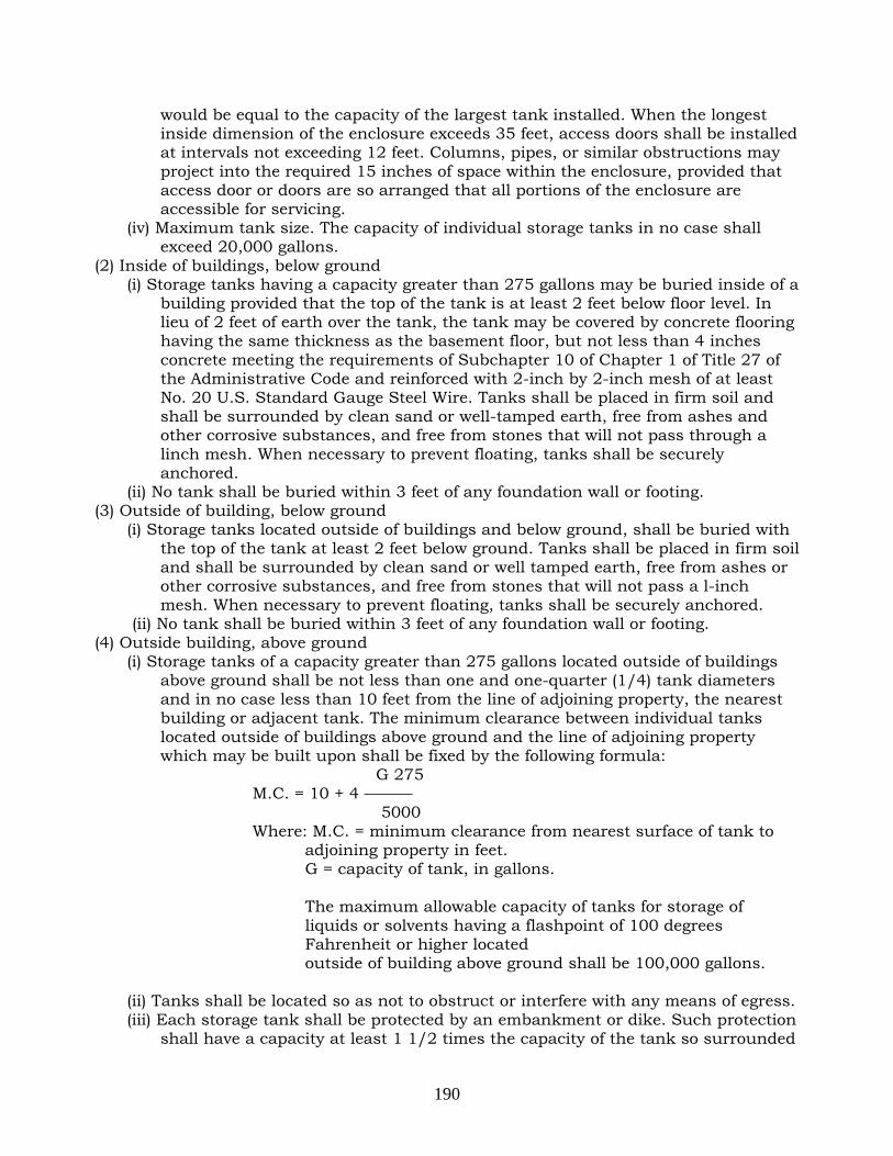
190
would be equal to the capacity of the largest tank installed. When the longest inside dimension of the enclosure exceeds 35 feet, access doors shall be installed at intervals not exceeding 12 feet. Columns, pipes, or similar obstructions may project into the required 15 inches of space within the enclosure, provided that access door or doors are so arranged that all portions of the enclosure are accessible for servicing.
(iv) Maximum tank size. The capacity of individual storage tanks in no case shall exceed 20,000 gallons.
(2) Inside of buildings, below ground (i) Storage tanks having a capacity greater than 275 gallons may be buried inside of a
building provided that the top of the tank is at least 2 feet below floor level. In lieu of 2 feet of earth over the tank, the tank may be covered by concrete flooring having the same thickness as the basement floor, but not less than 4 inches concrete meeting the requirements of Subchapter 10 of Chapter 1 of Title 27 of the Administrative Code and reinforced with 2-inch by 2-inch mesh of at least No. 20 U.S. Standard Gauge Steel Wire. Tanks shall be placed in firm soil and shall be surrounded by clean sand or well-tamped earth, free from ashes and other corrosive substances, and free from stones that will not pass through a linch mesh. When necessary to prevent floating, tanks shall be securely anchored.
(ii) No tank shall be buried within 3 feet of any foundation wall or footing. (3) Outside of building, below ground
(i) Storage tanks located outside of buildings and below ground, shall be buried with the top of the tank at least 2 feet below ground. Tanks shall be placed in firm soil and shall be surrounded by clean sand or well tamped earth, free from ashes or other corrosive substances, and free from stones that will not pass a l-inch mesh. When necessary to prevent floating, tanks shall be securely anchored.
(ii) No tank shall be buried within 3 feet of any foundation wall or footing. (4) Outside building, above ground
(i) Storage tanks of a capacity greater than 275 gallons located outside of buildings above ground shall be not less than one and one-quarter (1/4) tank diameters and in no case less than 10 feet from the line of adjoining property, the nearest building or adjacent tank. The minimum clearance between individual tanks located outside of buildings above ground and the line of adjoining property which may be built upon shall be fixed by the following formula:
G 275 M.C. = 10 + 4 ——— 5000 Where: M.C. = minimum clearance from nearest surface of tank to
adjoining property in feet. G = capacity of tank, in gallons. The maximum allowable capacity of tanks for storage of liquids or solvents having a flashpoint of 100 degrees Fahrenheit or higher located outside of building above ground shall be 100,000 gallons.
(ii) Tanks shall be located so as not to obstruct or interfere with any means of egress. (iii) Each storage tank shall be protected by an embankment or dike. Such protection
shall have a capacity at least 1 1/2 times the capacity of the tank so surrounded

191
and shall be at least 4 feet high, but in no case shall the protection be higher than 1/4 the height of the tank when the height of the tank exceeds 16 feet. Embankments or dikes shall be made of earth work with clay core, of masonry, or reinforced concrete or of steel. Earth work embankments shall be firmly and compactly built of good earth free from stones, vegetable matter, etc., and shall have a flat section of at least 3 feet at the top and slope of at least 1 1/2 to 2 feet on all sides. Concrete, masonry or steel dikes shall be designed so as to confine safely all of the oil in the tank so surrounded. Embankments or dikes shall be continuous and unpierced, and the outside toe shall be located at least 5 feet inside of the property line, and no less than 5 feet from a driveway or parking area.
(5) Tanks located along line of subways (i) No buried tank shall be placed within 20 feet of the outside line of a subway wall.
Where an above ground tank within a building is located within the outer lines of the subway, or within 20 feet of the outside line of the subway wall, such tank shall be placed within a welded steel oil-tight pan of not less than number 18 manufacturer's standard gauge metal suitably reinforced and of capacity to contain the contents of the tank.
(ii) For the purpose of the foregoing requirement, a subway shall be deemed to include any subsurface railroad or rapid transit roadbed.
(f) (1) Installation of piping and tubing
(i) Exposed piping shall be protected against mechanical damage and shall be adequately supported with rigid metal fasteners or hangers. All pipes connected to buried tanks, except test well piping, shall be provided with double swing joints at the tank.
(ii) Only new wrought iron, steel, or brass pipe, or type K or heavier copper tubing shall be used.
Metal tubing when used for conveying material shall be adequately protected. (iii) Overflow pipes, where installed, shall not be smaller in size than the supply pipe. (iv) Pipe shall be connected with standard fittings and tubing with fittings of listed or
approved type all of the same material as the pipe, except that malleable iron fittings may be used with steel pipe. Cast iron fittings shall not be used. All threaded joints and connections shall be made tight with suitable pipe compound. Unions requiring gaskets or packing, right or left couplings and sweat fittings employing solder having a melting point of less than 1,000 F. shall not be used.
(2) Relief valves (i) Where a shut-off valve is installed in the discharge line from a material pump, a
relief valve shall be installed in the discharge line between the pump and the first shut-off valve.
(ii) Relief valves shall be set to discharge at not more than 1 1/2 times the maximum working pressure of the system. The discharge from relief valves shall be returned to the storage tank or to the supply line. There shall be no shut-off valve in the line of relief.
(3) Vent pipes (i) A vent pipe of iron or steel, without trap, draining to the tank, shall be provided for
each storage tank. The lower end of the vent pipe shall not extend more than 1 inch through the top of the storage tank. Cross-connection between a vent pipe and fill pipe is prohibited.

192
(ii) Where a battery of storage tanks designed to hold identical material is installed, vent pipes may be run into a main header.
(iii) Vent shall be at least 1 1/4 inch in diameter for storage tanks not exceeding 1,100 gallon capacity and at least 2 inches in diameter for storage tanks of 1,100 gallons or more.
(iv) Vent pipes shall be provided with an approved weatherproof hood having a free area of at least the pipe size area. Vent pipes shall terminate outside the building in a non-hazardous location, at least 2 feet from any building opening and not less than 2 feet nor more than 12 feet above the fill pipe terminal unless otherwise permitted by the Commissioner. If the vent pipe terminal is not visible from the fill pipe terminal location, a one inch tell-tale line shall be connected to the tank and shall parallel the fill pipe and terminate at the fill terminal with an unthreaded end. Such telltale lines shall be provided with a check valve set to prevent flow of surface water to the storage tank.
(4) Fill pipes (i) Fill pipes shall terminate outside the buildings, with the fill pipe terminal located
at or above grade, at least 2 feet from any building opening and 5 feet from any subway grating at or below the level of the pipe terminal. No fill pipe shall be less than 2 inches in diameter.
(ii) Each storage tank shall be provided with a separate fill pipe, except that where a battery of tanks is installed containing identical materials, a common fill and header pipe may be installed.
(iii) Where the top of the storage tank is above the fill pipe terminal, the fill pipe shall be connected to the top of the tank and provided with a shut-off valve and swing check valve both of which shall be located at the fill pipe terminal. However, the shut-off and check valves may be installed in an accessible location inside the building at or below the level of the fill pipe terminal.
(iv) All fill pipe terminals shall be of a type identical to that approved for fuel oil service, and shall be provided with lugs for embedding concrete. In lieu of lugs, a set screw or threads to fasten the terminal to the fill pipe may be used. The outer flange of the fill pipe terminal or the seal cap shall be permanently marked to identify contents. The fill pipe terminal shall be threaded or provided with other equivalent means to receive the seal cap. The seal cap shall be suitably slotted for receiving an opening wrench, and an oil proof gasket inserted in a groove in the fill pipe terminal shall be provided so as to make the seal cap leakproof. A strainer shall not be required but, if used, shall be of at least 1/8-inch mesh. Where a storage system for volatile flammable oil and a storage system for liquid flashing at 100 degrees Fahrenheit or higher is to be used in the same premises, the terminal of liquid flashing 100 degrees Fahrenheit or higher storage system shall be provided with a left-headed thread and the fill pipe fitting shall be of a different size than that required for the fill pipes to the tanks containing the volatile flammable oil.
(5) Piping from transfer pump to manufacturing equipment above the lowest floor (i) The piping from a transfer pump to "manufacturing equipment" at levels above the
lowest floor in buildings, the return piping, and vent piping shall comply with the applicable provisions of paragraphs (1), (3) and (4) of this subdivision (f) and shall be enclosed in a shaft constructed of 4 inch concrete or masonry having a 4 inch clearance from all pipe or pipe covering. Provisions shall be made for expansion in piping without the use of expansion joints.

193
(ii) Where it is necessary to make horizontal offsets in the supply piping and pipe shafts such piping shall be enclosed in a sleeve of other piping of at least number 10 manufacturer's standard gauge steel, two sizes larger and arranged to drain into the shaft. Horizontal piping offsets shall be further enclosed in construction having a 2-hour fire resistance rating.
(iii) A drain pipe shall be installed at the base of shafts enclosing the supply and overflow piping. The pipe shall lead to an open sight drain or to an open sump.
(iv) Pipe lines for manufacturing equipment above the level of the lowest floor shall be seamless steel pipe of a weight not less than ASA schedule 40 with welded connections.
(v) Pipe shafts shall not be penetrated by or contain other piping or ducts.
(g) Valves and devices to control the flow of materials (1) Approved leak detectors on discharge piping shall be provided for submerged or
remote control pumps. (2) A clearly identified remote control switch readily accessible, shall be provided on each
floor to which material is pumped to shut-off the power to the pump motors. (3) A visible means shall be provided for each discharge area to indicate when pump is
operating. (4) Pumps shall be of a type approved by Board of Standards and Appeals. (5) Pressure in storage tanks for the purpose of discharging materials is prohibited. (h) Material level indicating devices and test wells (1) All tanks located inside buildings shall be provided with a material level indicating
device. Test wells shall be prohibited in tanks located inside of buildings. Unused tank openings shall be permanently sealed to prevent the removal of plugs or cover.
(2) Material level indicating devices shall be designed and constructed of substantial materials so that there can be no leakage of materials or vapor from the material.
(3) Test wells in storage tanks located outside of buildings shall be capped oil tight and kept closed when not in use. (i) Tests. All piping and storage tanks for materials flashing at 100 degrees
Fahrenheit or higher shall be tested hydrostatically in the presence of a Fire Department representative before work is closed in. The hydrostatic pressure shall be maintained until all joints and connections have been visually inspected, for leaks but in no case for less than one-half hour. The minimum pressure for testing tanks shall be at least 25 pounds per square inch. The piping shall be tested at 1 1/2 times maximum work pressure applicable to that part of the piping system but in no case less than 25 pounds per square inch. For storage systems for materials flashing above 300 degrees Fahrenheit contractor may submit a notarized affidavit attesting to testing of tank and piping as prescribed above, in lieu of the Fire Department witnessed test.