Embed Size (px)
Citation preview
Danfoss scroll compressors VZH088-117-170 Gen3SingleR410A
Application guidelines
www.danfoss.com

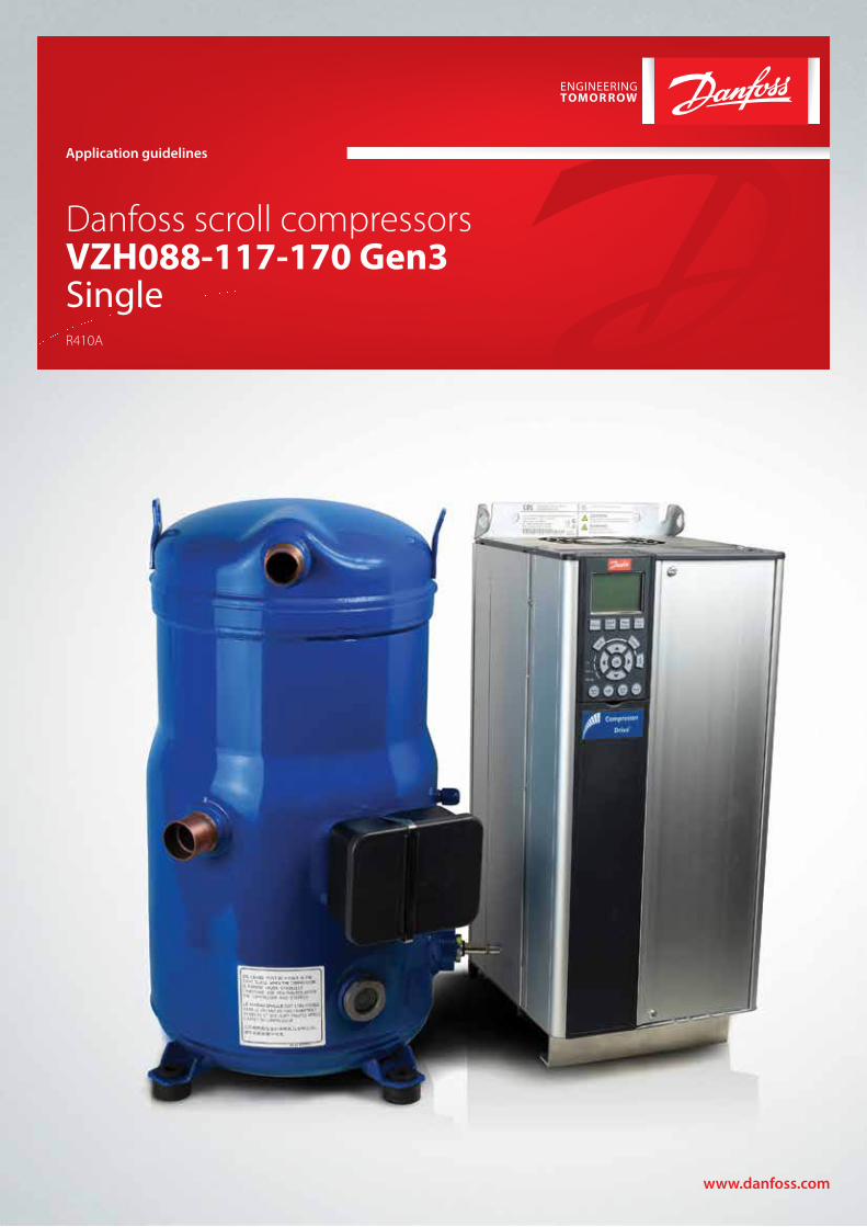
Content
GENERAL INFORMATION ........................ 4
Features..................................................... 5
Compressor model designation ............. 6
Technical specifications ........................... 7
Dimensions ............................................. 10
Electrical data, connections and wiring 24Supply voltage ........................................................... 24Phase sequence and reverse rotation protection .................................................................... 27Sound level and acoustic hood ........................... 28IP rating ......................................................................... 29Motor protection ....................................................... 29
Approval and certificates ...................... 30
SYSTEM DESIGN ..................................... 31
System design generalities ................... 31Compressor capacity and modulation ..............31Differences between variable speed and fix in speed unit design ............................................31
Compressor and drive control .............. 32Typical control architecture .................................. 32Oil injection control ................................................. 32Compressor start and stop, speed control ...... 33Short cycle protection............................................. 34Drive alarm .................................................................. 35Stop compressor in case of safeties (LP, HP, DGT) ................................................ 354 Way valve control and defrost logic ............... 36Unit remotely controlled ........................................ 36
Superheat management ........................ 37Oil superheat measurement during qualification ...................................................37Test and components required per application .......................................................... 38Liquid floodback and defrost test....................... 38Expansion valve ......................................................... 39Selection of expansion valve ................................ 39Adjustment of exv control parameters ............ 40Location and installation of bulb (TXV) or pressure and temperature sensor (EXV) ......41Suction accumulator .................................................41
Oil return management ......................... 42Test and components required per application ............................................................42Oil return test ...............................................................42Piping recommendations to ensure oil return ....................................................................... 43Oil boost ....................................................................... 44Oil separator................................................................ 46
Prevent off cycle migration ................... 47Compressor charge limit .........................................47Test and components required per application ...........................................................47Test and components required per application ...........................................................47Surface sump heater ................................................ 48Surface sump heater control logic ..................... 48Non return valve ........................................................ 48Liquid line solenoid valve ...................................... 49Pump down cycle ..................................................... 49
Operating envelope ............................... 50Compressor envelope and pressure settings . 50Protection and control of envelope ....................51High pressure switch ............................................... 53Operating envelope ................................................. 54Low pressure switch ................................................. 54Discharge gas thermostat ..................................... 54MOP (Max Operating Pressure Control) ...........55
Sound and vibrations management ..... 56Sound level .................................................................. 56Vibrations ..................................................................... 56Gas pulsation .............................................................. 56
Compressor mechanical installation .... 57Grommets .................................................................... 57Max inclination........................................................... 57
Drive installation .................................... 58Direct and indirect exposure of drive to water ........................................................................ 58Dust Exposure ............................................................ 58Mechanical Mounting ............................................. 58Drive ambient temperature ...................................59EMC ................................................................................ 60EMC best practices ................................................... 60EMC correct installation of an frequency drive CDS303 ............................................................... 60
INTEGRATION INTO SYSTEMS .............. 61
Assembly line procedure ....................... 61Reduce moisture in the system ............................61Requirements ..............................................................61Solutions........................................................................61Compressor storage ..................................................61Compressor holding charge ..................................61Handling .......................................................................61Piping assembly ......................................................... 62System pressure test and leak detection ......... 62Vacuum evacuation and moisture removal ... 63Refrigerant charging ................................................ 63Dielectric strength and insulation resistance tests ........................................................... 63
Commissioning ....................................... 64Preliminary check ...................................................... 64Initial start-up ............................................................. 64System monitoring ................................................... 64Oil level checking and top-up .............................. 64
Troubleshooting ..................................... 65
Dismantal and disposal ......................... 68
Packaging ............................................... 69
Ordering codes ....................................... 70
Accessories .............................................. 73
3AB300034185311en-000101
GEN
ERA
L IN
FOR
MAT
ION
PR
OD
UC
T IN
FOR
MAT
ION
SYST
EM D
ESIG
NIN
TEG
RAT
ION
INTO
SY
STEM
OR
DER
ING
INFO
RM
ATIO
N
General Information
Danfoss scroll compressors are designed and manufactured with state of the art technology and follow European and US regulations. There is an added emphasis placed on safety and reliability. Critical instructions are highlighted with the following icons:
This icon indicates instructions to avoid safety risk.
This icon indicates instructions to avoid reliability risk.
The purpose of this guideline is informational, with the intent to educate customers as to how the compressors should properly function. If you need any additional assistance, please contact Danfoss Technichal Support. In any case, Danfoss manufacturing accepts no liability as a result of misuse or improper integration of the compressor unit.
R
4 AB300034185311en-000101
GEN
ERA
L IN
FOR
MAT
ION
PR
OD
UC
T IN
FOR
MAT
ION
SYST
EM D
ESIG
NIN
TEG
RAT
ION
INTO
SY
STEM
OR
DER
ING
INFO
RM
ATIO
N
Features
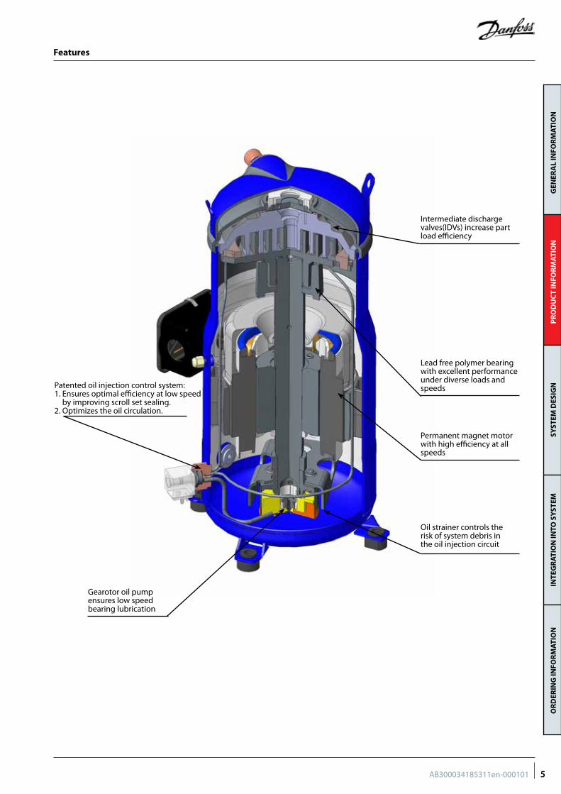
Patented oil injection control system:1. Ensures optimal efficiency at low speed
by improving scroll set sealing.2. Optimizes the oil circulation.
Intermediate discharge valves(IDVs) increase part load efficiency
Lead free polymer bearing with excellent performance under diverse loads and speeds
Permanent magnet motor with high efficiency at all speeds
Oil strainer controls the risk of system debris in the oil injection circuit
Gearotor oil pump ensures low speed bearing lubrication
5AB300034185311en-000101
GEN
ERA
L IN
FOR
MAT
ION
PR
OD
UC
T IN
FOR
MAT
ION
SYST
EM D
ESIG
NIN
TEG
RAT
ION
INTO
SY
STEM
OR
DER
ING
INFO
RM
ATIO
N
Compressor model designation
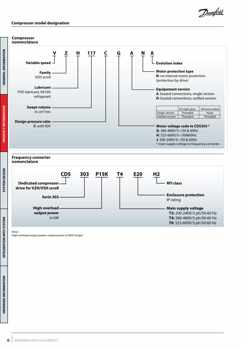
Compressor nomenclature
Frequency converter nomenclature
ANAGC117Z HV
Variable speed
FamilyVZH scroll
LubricantPOE lubricant, R410A
refrigerant
Swept volumein cm³/rev
Design pressure ratioC: with IDV
Evolution index
Motor protection typeN: no internal motor protection (protection by drive)
Equipement versionA: brazed connections, single versionD: brazed connections, unified version
Motor voltage code to CDS303 *G: 380-480V/3~/50 & 60HzH: 525-600V/3~/50&60Hz J: 200-240V/3~/50 & 60Hz* main supply voltage to frequency converter
Oil sight glass Oil level switchSingle version Threaded NoneUnified version Threaded Threaded
H2E20T4P15K303CDS
Dedicated compressor drive for VZH/VSH scroll
Serie 303
High overload output power
in kW
Main supply voltageT2: 200-240V/3 ph/50-60 HzT4: 380-480V/3 ph/50-60 HzT6: 525-600V/3 ph/50-60 Hz
RFI class
Enclosure protectionIP rating
Note: High overload output power: output power @160% Torque
6 AB300034185311en-000101
GEN
ERA
L IN
FOR
MAT
ION
PR
OD
UC
T IN
FOR
MAT
ION
SYST
EM D
ESIG
NIN
TEG
RAT
ION
INTO
SY
STEM
OR
DER
ING
INFO
RM
ATIO
N
Technical specifications
Compressor can be sized on peak load, for best applied cost, or optimal efficiency. For optimal
efficiency, see our performance details in Coolselector software.
Compressor size
Different frequency converter variants are available according to: 1. Mains supply voltage2. IP class (CDS303 drives are available in IP20 or
IP55 housings)
3. RFI (Radio Frequency Interference) class H2/H3 or HX
4. Printed Circuit Board (PCB) coated or not coated.
When the compressor size and mains voltage have been defined in the above selection criteria, the code number tables from the “Ordering information and packaging” section provides the appropriate frequency converter sizes and up to eight corresponding code numbers for each compressor model.
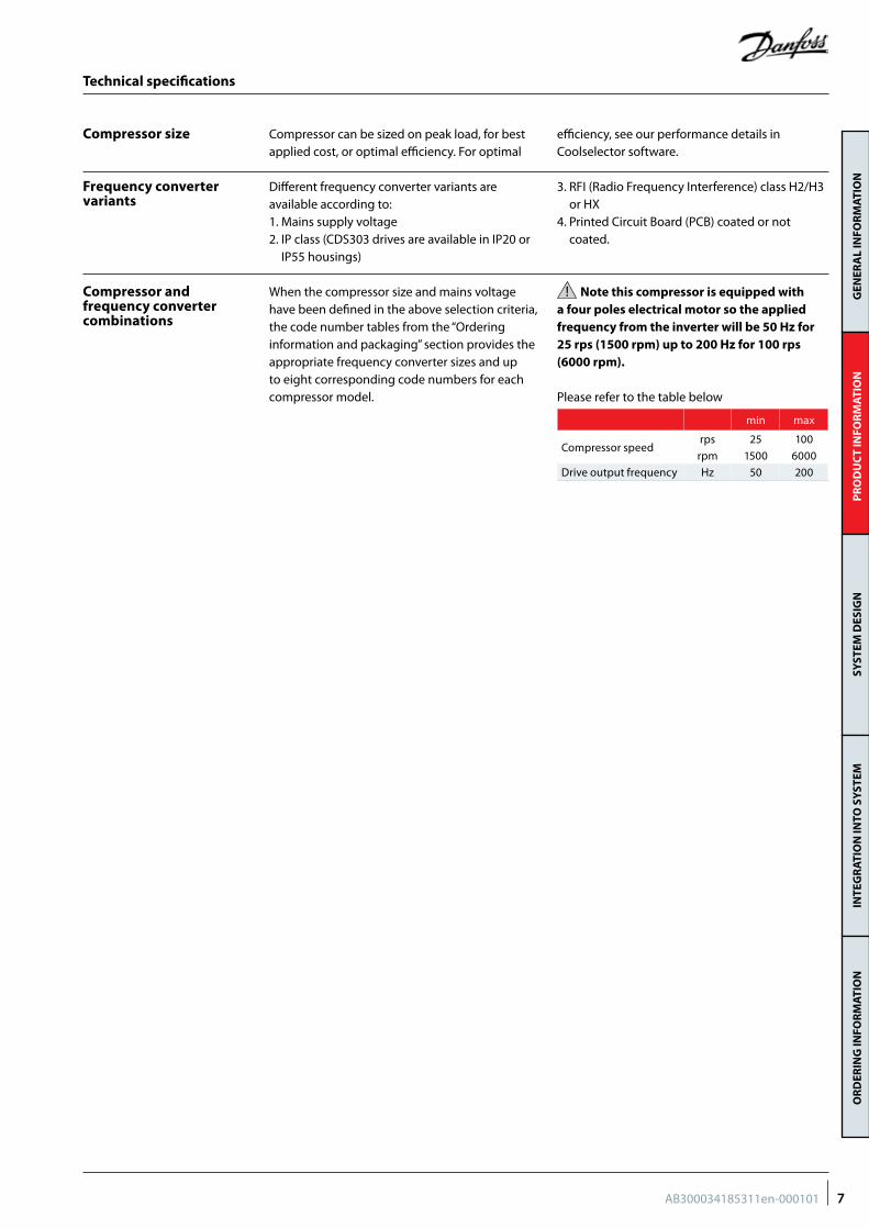
Note this compressor is equipped with a four poles electrical motor so the applied frequency from the inverter will be 50 Hz for 25 rps (1500 rpm) up to 200 Hz for 100 rps (6000 rpm).
Please refer to the table below
Frequency converter variants
Compressor and frequency converter combinations
min max
Compressor speedrps 25 100
rpm 1500 6000
Drive output frequency Hz 50 200
7AB300034185311en-000101
GEN
ERA
L IN
FOR
MAT
ION
PR
OD
UC
T IN
FOR
MAT
ION
SYST
EM D
ESIG
NIN
TEG
RAT
ION
INTO
SY
STEM
OR
DER
ING
INFO
RM
ATIO
N
Technical specifications
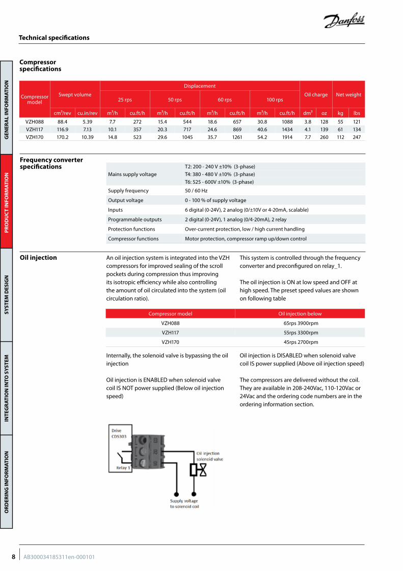
Compressor specifications
Frequency converter specifications
Mains supply voltage
T2: 200 - 240 V ±10% (3-phase)
T4: 380 - 480 V ±10% (3-phase)
T6: 525 - 600V ±10% (3-phase)
Supply frequency 50 / 60 Hz
Output voltage 0 - 100 % of supply voltage
Inputs 6 digital (0-24V), 2 analog (0/±10V or 4-20mA, scalable)
Programmable outputs 2 digital (0-24V), 1 analog (0/4-20mA), 2 relay
Protection functions Over-current protection, low / high current handling
Compressor functions Motor protection, compressor ramp up/down control
Compressor model
Swept volume
Displacement
Oil charge Net weight25 rps 50 rps 60 rps 100 rps
cm³/rev cu.in/rev m³/h cu.ft/h m³/h cu.ft/h m³/h cu.ft/h m³/h cu.ft/h dm³ oz kg lbs
VZH088 88.4 5.39 7.7 272 15.4 544 18.6 657 30.8 1088 3.8 128 55 121
VZH117 116.9 7.13 10.1 357 20.3 717 24.6 869 40.6 1434 4.1 139 61 134
VZH170 170.2 10.39 14.8 523 29.6 1045 35.7 1261 54.2 1914 7.7 260 112 247
Oil injection An oil injection system is integrated into the VZH compressors for improved sealing of the scroll pockets during compression thus improving its isotropic efficiency while also controlling the amount of oil circulated into the system (oil circulation ratio).
This system is controlled through the frequency converter and preconfigured on relay_1.
The oil injection is ON at low speed and OFF at high speed. The preset speed values are shown on following table
Internally, the solenoid valve is bypassing the oil injection
Oil injection is ENABLED when solenoid valve coil IS NOT power supplied (Below oil injection speed)
Oil injection is DISABLED when solenoid valve coil IS power supplied (Above oil injection speed)
The compressors are delivered without the coil. They are available in 208-240Vac, 110-120Vac or 24Vac and the ordering code numbers are in the ordering information section.
Compressor model Oil injection below
VZH088 65rps 3900rpm
VZH117 55rps 3300rpm
VZH170 45rps 2700rpm
8 AB300034185311en-000101
GEN
ERA
L IN
FOR
MAT
ION
PR
OD
UC
T IN
FOR
MAT
ION
SYST
EM D
ESIG
NIN
TEG
RAT
ION
INTO
SY
STEM
OR
DER
ING
INFO
RM
ATIO
N
Technical specifications
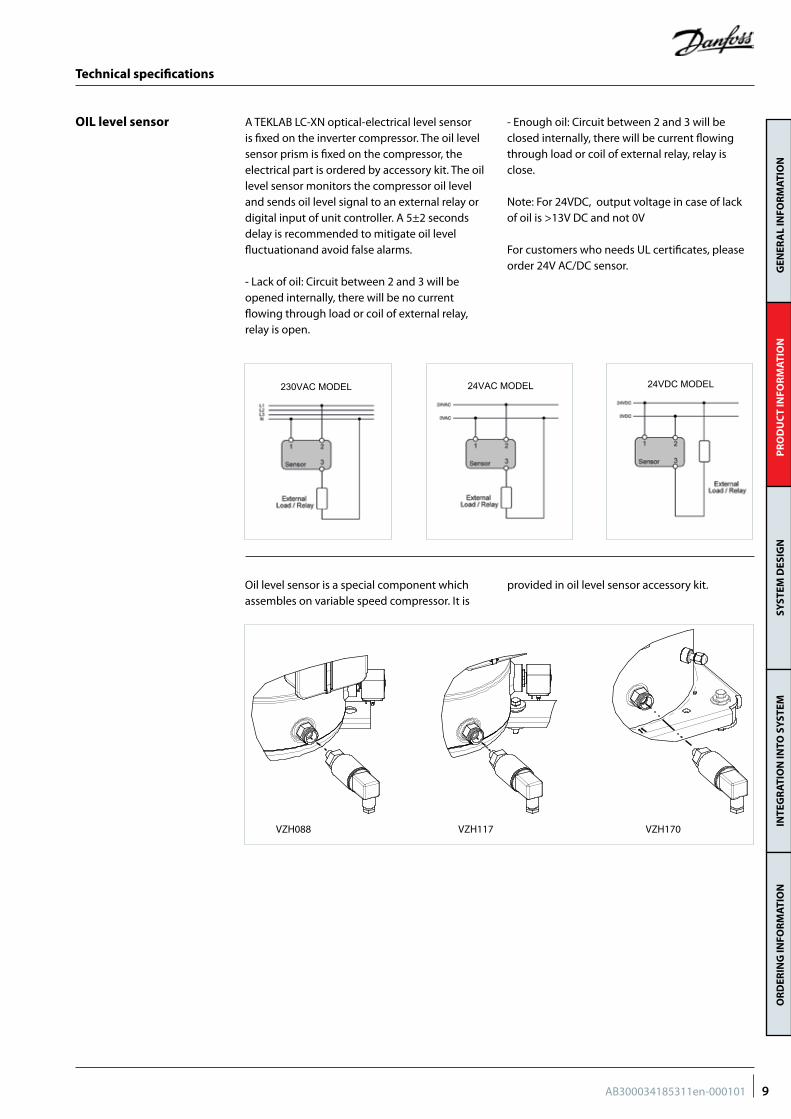
OIL level sensor A TEKLAB LC-XN optical-electrical level sensor is fixed on the inverter compressor. The oil level sensor prism is fixed on the compressor, the electrical part is ordered by accessory kit. The oil level sensor monitors the compressor oil level and sends oil level signal to an external relay or digital input of unit controller. A 5±2 seconds delay is recommended to mitigate oil level fluctuationand avoid false alarms.
- Lack of oil: Circuit between 2 and 3 will be opened internally, there will be no current flowing through load or coil of external relay, relay is open.
- Enough oil: Circuit between 2 and 3 will be closed internally, there will be current flowing through load or coil of external relay, relay is close.
Note: For 24VDC, output voltage in case of lack of oil is >13V DC and not 0V
For customers who needs UL certificates, please order 24V AC/DC sensor.
24VDC MODEL
230VAC MODEL
24VAC MODEL
24VDC MODEL
230VAC MODEL
24VAC MODEL
24VDC MODEL
230VAC MODEL
24VAC MODEL
Oil level sensor is a special component which assembles on variable speed compressor. It is
provided in oil level sensor accessory kit.
VZH088 VZH117 VZH170
9AB300034185311en-000101
GEN
ERA
L IN
FOR
MAT
ION
PR
OD
UC
T IN
FOR
MAT
ION
SYST
EM D
ESIG
NIN
TEG
RAT
ION
INTO
SY
STEM
OR
DER
ING
INFO
RM
ATIO
N
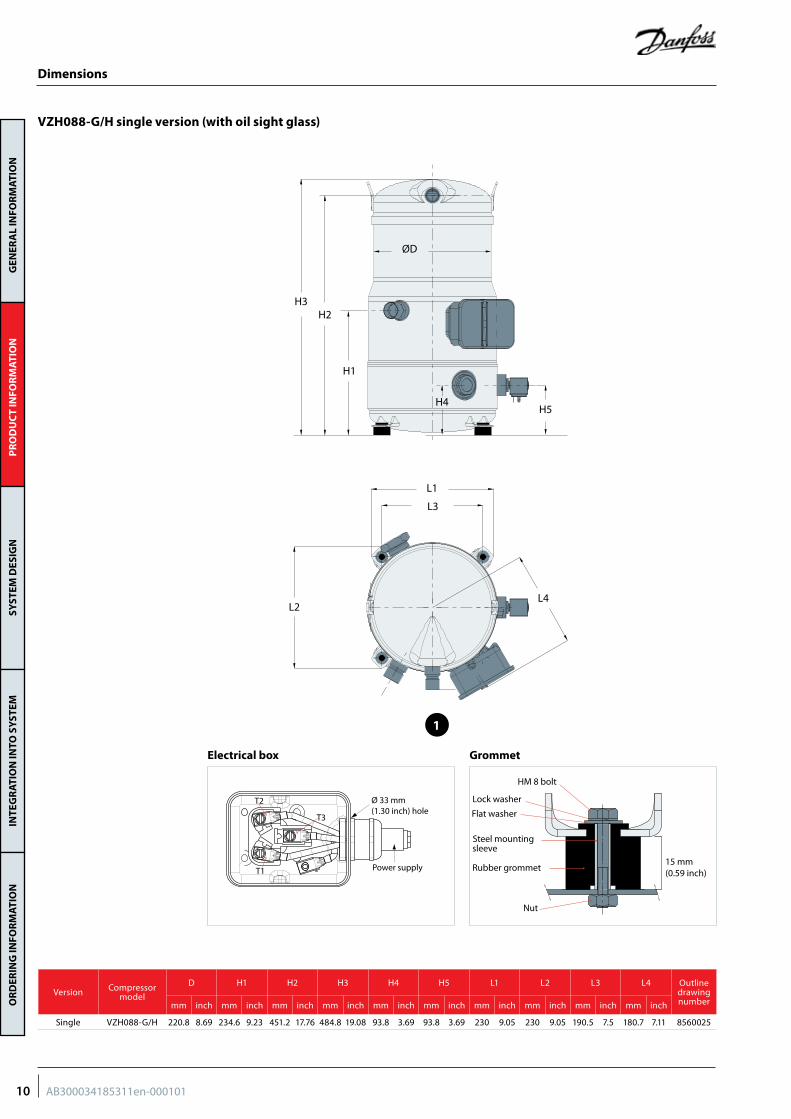
VZH088-G/H single version (with oil sight glass)
ØD
H3
H1
H5
L1
L2
L3
L4
H2
H4
Dimensions
15 mm(0.59 inch)
HM 8 bolt
Lock washer
Flat washer
Steel mountingsleeve
Rubber grommet
Nut
Ø 33 mm (1.30 inch) hole
T2
T1
T3
Power supply
GrommetElectrical box
Version Compressor model
D H1 H2 H3 H4 H5 L1 L2 L3 L4 Outline drawing numbermm inch mm inch mm inch mm inch mm inch mm inch mm inch mm inch mm inch mm inch
Single VZH088-G/H 220.8 8.69 234.6 9.23 451.2 17.76 484.8 19.08 93.8 3.69 93.8 3.69 230 9.05 230 9.05 190.5 7.5 180.7 7.11 8560025
1
10 AB300034185311en-000101
GEN
ERA
L IN
FOR
MAT
ION
PR
OD
UC
T IN
FOR
MAT
ION
SYST
EM D
ESIG
NIN
TEG
RAT
ION
INTO
SY
STEM
OR
DER
ING
INFO
RM
ATIO
N
2
Version Compressor model
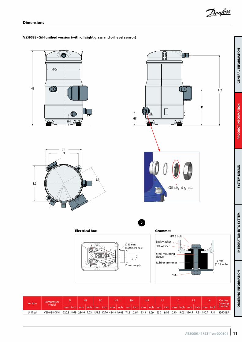
D H1 H2 H3 H4 H5 L1 L2 L3 L4 Outline drawing numbermm inch mm inch mm inch mm inch mm inch mm inch mm inch mm inch mm inch mm inch
Unified VZH088-G/H 220.8 8.69 234.6 9.23 451.2 17.76 484.8 19.08 74.8 2.94 93.8 3.69 230 9.05 230 9.05 190.5 7.5 180.7 7.11 8560097
VZH088 -G/H unified version (with oil sight glass and oil level sensor)
ØD
H3
L1
L2
L3
L4
H4H5
H2
H1
15 mm(0.59 inch)
HM 8 bolt
Lock washer
Flat washer
Steel mountingsleeve
Rubber grommet
Nut
Ø 33 mm (1.30 inch) hole
T2
T1
T3
Power supply
GrommetElectrical box
Dimensions
Oil sight glass
11AB300034185311en-000101

GEN
ERA
L IN
FOR
MAT
ION
PR
OD
UC
T IN
FOR
MAT
ION
SYST
EM D
ESIG
NIN
TEG
RAT
ION
INTO
SY
STEM
OR
DER
ING
INFO
RM
ATIO
N
Dimensions
VZH088-J single version (with oil sight glass)
L1
L4
L3
L2
H5
H2
ØD
H1
H3
H4
15 mm(0.59 inch)
HM 8 bolt
Lock washer
Flat washer
Steel mountingsleeve
Rubber grommet
Nut
Ø 40.5 mm(1.59 inch) hole
Ø 16.5 mm(0.65 inch) knockout
Power supply
T2
T1
T3
GrommetElectrical box
Version Compressor model
D H1 H2 H3 H4 H5 L1 L2 L3 L4 Outline drawing numbermm inch mm inch mm inch mm inch mm inch mm inch mm inch mm inch mm inch mm inch
Single VZH088-J 220.8 8.69 234.6 9.23 451.2 17.76 484.8 19.08 93.8 3.69 93.8 3.69 230 9.05 230 9.05 190.5 7.5 200.4 7.81 8560030
3
12 AB300034185311en-000101
GEN
ERA
L IN
FOR
MAT
ION
PR
OD
UC
T IN
FOR
MAT
ION
SYST
EM D
ESIG
NIN
TEG
RAT
ION
INTO
SY
STEM
OR
DER
ING
INFO
RM
ATIO
N
4
Version Compressor model
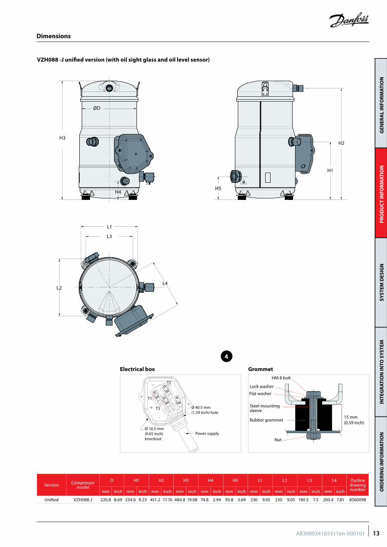
D H1 H2 H3 H4 H5 L1 L2 L3 L4 Outline drawing numbermm inch mm inch mm inch mm inch mm inch mm inch mm inch mm inch mm inch mm inch
Unified VZH088-J 220.8 8.69 234.6 9.23 451.2 17.76 484.8 19.08 74.8 2.94 93.8 3.69 230 9.05 230 9.05 190.5 7.5 200.4 7.81 8560098
VZH088 -J unified version (with oil sight glass and oil level sensor)
ØD
H3
H4
H1
H2
H5
L1
L2L4
L3
Dimensions
15 mm(0.59 inch)
HM 8 bolt
Lock washer
Flat washer
Steel mountingsleeve
Rubber grommet
Nut
Ø 40.5 mm(1.59 inch) hole
Ø 16.5 mm(0.65 inch) knockout
Power supply
T2
T1
T3
GrommetElectrical box
13AB300034185311en-000101
GEN
ERA
L IN
FOR
MAT
ION
PR
OD
UC
T IN
FOR
MAT
ION
SYST
EM D
ESIG
NIN
TEG
RAT
ION
INTO
SY
STEM
OR
DER
ING
INFO
RM
ATIO
N
Dimensions
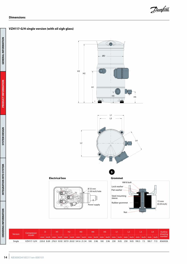
VZH117-G/H single version (with oil sigh glass)
H2
H1
H3
ØD
H5
L1
L2L4
L3
H4
15 mm(0.59 inch)
HM 8 bolt
Lock washer
Flat washer
Steel mountingsleeve
Rubber grommet
Nut
Ø 33 mm (1.30 inch) hole
T2
T1
T3
Power supply
GrommetElectrical box
5
Version Compressor model
D H1 H2 H3 H4 H5 L1 L2 L3 L4 Outline drawing numbermm inch mm inch mm inch mm inch mm inch mm inch mm inch mm inch mm inch mm inch
Single VZH117- G/H 220.8 8.69 276.9 10.92 507.9 20.02 541.6 21.34 100 3.96 100 3.96 230 9.05 230 9.05 190.5 7.5 180.7 7.13 8560026
14 AB300034185311en-000101
GEN
ERA
L IN
FOR
MAT
ION
PR
OD
UC
T IN
FOR
MAT
ION
SYST
EM D
ESIG
NIN
TEG
RAT
ION
INTO
SY
STEM
OR
DER
ING
INFO
RM
ATIO
N
6
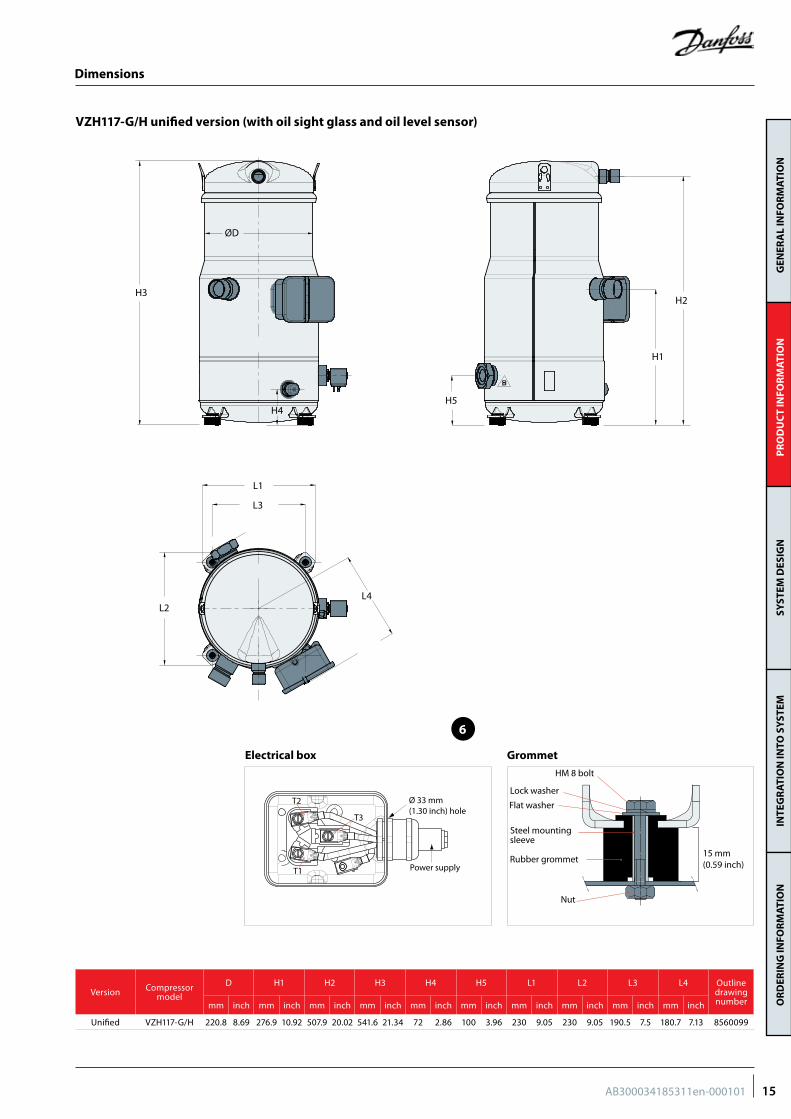
VZH117-G/H unified version (with oil sight glass and oil level sensor)
ØD
H3
H4H5
H1
H2
L1
L2
L3
L4
Dimensions
15 mm(0.59 inch)
HM 8 bolt
Lock washer
Flat washer
Steel mountingsleeve
Rubber grommet
Nut
Ø 33 mm (1.30 inch) hole
T2
T1
T3
Power supply
GrommetElectrical box
Version Compressor model
D H1 H2 H3 H4 H5 L1 L2 L3 L4 Outline drawing numbermm inch mm inch mm inch mm inch mm inch mm inch mm inch mm inch mm inch mm inch
Unified VZH117-G/H 220.8 8.69 276.9 10.92 507.9 20.02 541.6 21.34 72 2.86 100 3.96 230 9.05 230 9.05 190.5 7.5 180.7 7.13 8560099
15AB300034185311en-000101
GEN
ERA
L IN
FOR
MAT
ION
PR
OD
UC
T IN
FOR
MAT
ION
SYST
EM D
ESIG
NIN
TEG
RAT
ION
INTO
SY
STEM
OR
DER
ING
INFO
RM
ATIO
N
Dimensions
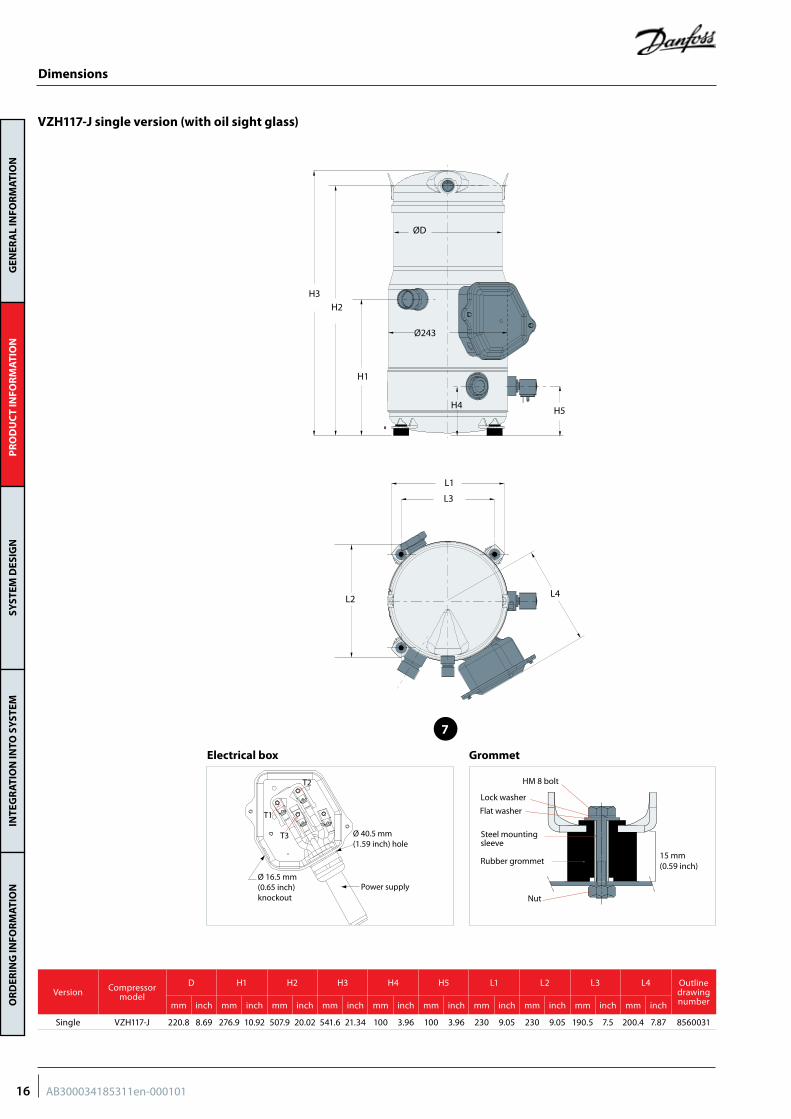
VZH117-J single version (with oil sight glass)
L1
L2
L3
ØD
Ø243
H3
H1
H5
L4
H2
H4
15 mm(0.59 inch)
HM 8 bolt
Lock washer
Flat washer
Steel mountingsleeve
Rubber grommet
Nut
Ø 40.5 mm(1.59 inch) hole
Ø 16.5 mm(0.65 inch) knockout
Power supply
T2
T1
T3
GrommetElectrical box
7
Version Compressor model
D H1 H2 H3 H4 H5 L1 L2 L3 L4 Outline drawing numbermm inch mm inch mm inch mm inch mm inch mm inch mm inch mm inch mm inch mm inch
Single VZH117-J 220.8 8.69 276.9 10.92 507.9 20.02 541.6 21.34 100 3.96 100 3.96 230 9.05 230 9.05 190.5 7.5 200.4 7.87 8560031
16 AB300034185311en-000101
GEN
ERA
L IN
FOR
MAT
ION
PR
OD
UC
T IN
FOR
MAT
ION
SYST
EM D
ESIG
NIN
TEG
RAT
ION
INTO
SY
STEM
OR
DER
ING
INFO
RM
ATIO
N
8
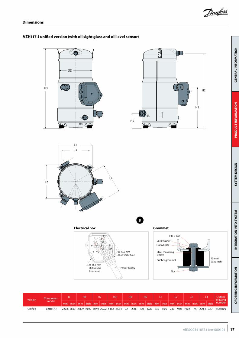
VZH117-J unified version (with oil sight glass and oil level sensor)
ØD
H3
L1
L2
L3
L4
H4H5
H1
H2
Dimensions
Version Compressor model
D H1 H2 H3 H4 H5 L1 L2 L3 L4 Outline drawing numbermm inch mm inch mm inch mm inch mm inch mm inch mm inch mm inch mm inch mm inch
Unified VZH117-J 220.8 8.69 276.9 10.92 507.9 20.02 541.6 21.34 72 2.86 100 3.96 230 9.05 230 9.05 190.5 7.5 200.4 7.87 8560100
15 mm(0.59 inch)
HM 8 bolt
Lock washer
Flat washer
Steel mountingsleeve
Rubber grommet
Nut
Ø 40.5 mm(1.59 inch) hole
Ø 16.5 mm(0.65 inch) knockout
Power supply
T2
T1
T3
GrommetElectrical box
17AB300034185311en-000101
GEN
ERA
L IN
FOR
MAT
ION
PR
OD
UC
T IN
FOR
MAT
ION
SYST
EM D
ESIG
NIN
TEG
RAT
ION
INTO
SY
STEM
OR
DER
ING
INFO
RM
ATIO
N
Dimensions
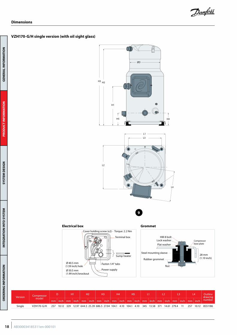
VZH170-G/H single version (with oil sight glass)
ØD
H2
H1
H5 H4
L1
L4
L2
L3
H3
HM 8 boltLock washer
Flat washer
Steel mounting sleeve
Rubber grommet
Nut
28 mm(1.10 inch)
Compressorbase plate
Cover holding screw (x2) - Torque: 2.2 Nm
Faston 1/4" tabs
Terminal box
Power supply
Sump heater
Ø 40.5 mm(1.59 inch) hole
Ø 50.5 mm(1.99 inch) knockout
T1 T2T3T3
GrommetElectrical box
9
Version Compressor model
D H1 H2 H3 H4 H5 L1 L2 L3 L4 Outline drawing numbermm inch mm inch mm inch mm inch mm inch mm inch mm inch mm inch mm inch mm inch
Single VZH170-G/H 257 10.12 329 12.97 644.5 25.39 686.5 27.04 104.1 4.10 104.1 4.10 345 13.58 371 14.61 279.4 11 257 10.12 8551186
18 AB300034185311en-000101
GEN
ERA
L IN
FOR
MAT
ION
PR
OD
UC
T IN
FOR
MAT
ION
SYST
EM D
ESIG
NIN
TEG
RAT
ION
INTO
SY
STEM
OR
DER
ING
INFO
RM
ATIO
N
10
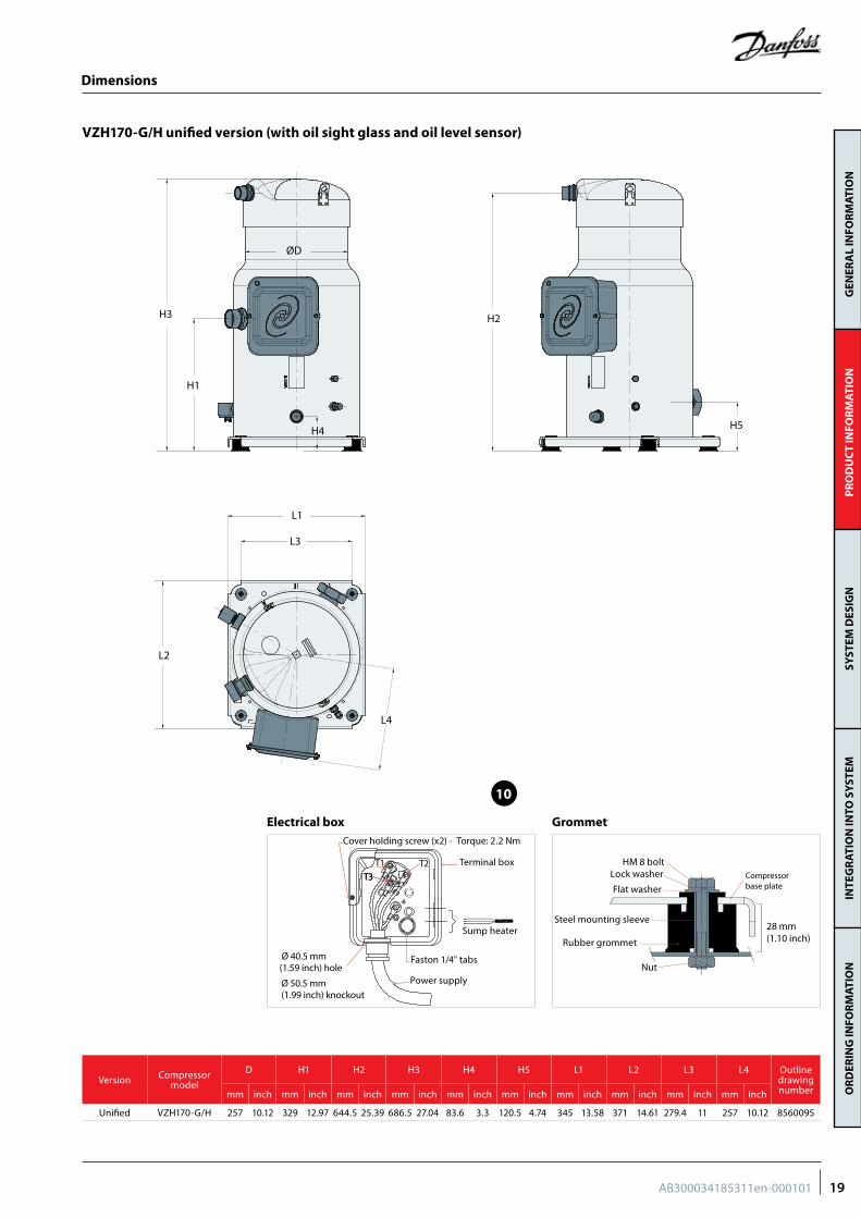
VZH170-G/H unified version (with oil sight glass and oil level sensor)
ØD
H2
H5
L1
L4
L2
L3
H1
H3
H4
Dimensions
Version Compressor model
D H1 H2 H3 H4 H5 L1 L2 L3 L4 Outline drawing numbermm inch mm inch mm inch mm inch mm inch mm inch mm inch mm inch mm inch mm inch
Unified VZH170-G/H 257 10.12 329 12.97 644.5 25.39 686.5 27.04 83.6 3.3 120.5 4.74 345 13.58 371 14.61 279.4 11 257 10.12 8560095
HM 8 boltLock washer
Flat washer
Steel mounting sleeve
Rubber grommet
Nut
28 mm(1.10 inch)
Compressorbase plate
Cover holding screw (x2) - Torque: 2.2 Nm
Faston 1/4" tabs
Terminal box
Power supply
Sump heater
Ø 40.5 mm(1.59 inch) hole
Ø 50.5 mm(1.99 inch) knockout
T1 T2T3T3
GrommetElectrical box
19AB300034185311en-000101
GEN
ERA
L IN
FOR
MAT
ION
PR
OD
UC
T IN
FOR
MAT
ION
SYST
EM D
ESIG
NIN
TEG
RAT
ION
INTO
SY
STEM
OR
DER
ING
INFO
RM
ATIO
N
Dimensions
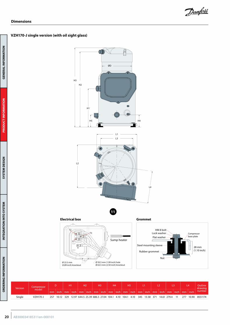
VZH170-J single version (with oil sight glass)
ØD
H1
H5
L1
L3
L2
L4
H4
H2
H3
HM 8 boltLock washer
Flat washer
Steel mounting sleeve
Rubber grommet
Nut
28 mm(1.10 inch)
Compressorbase plate
Ø 50.5 mm (1.99 inch) holeØ 63.5 mm (2.50 inch) knockout
T1
T2
T3
Ø 22.5 mm(0.89 inch) knockout
Sump heater
GrommetElectrical box
11
Version Compressor model
D H1 H2 H3 H4 H5 L1 L2 L3 L4 Outline drawing numbermm inch mm inch mm inch mm inch mm inch mm inch mm inch mm inch mm inch mm inch
Single VZH170-J 257 10.12 329 12.97 644.5 25.39 686.5 27.04 104.1 4.10 104.1 4.10 345 13.58 371 14.61 279.4 11 277 10.90 8551174
20 AB300034185311en-000101
GEN
ERA
L IN
FOR
MAT
ION
PR
OD
UC
T IN
FOR
MAT
ION
SYST
EM D
ESIG
NIN
TEG
RAT
ION
INTO
SY
STEM
OR
DER
ING
INFO
RM
ATIO
N
12
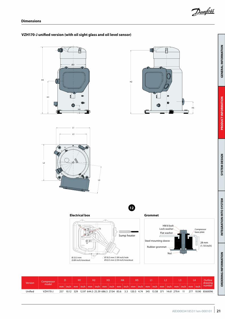
VZH170-J unified version (with oil sight glass and oil level sensor)
ØD
H4
H3
L1
L2
L3
H2
H5
H1
L4
Dimensions
Version Compressor model
D H1 H2 H3 H4 H5 L1 L2 L3 L4 Outline drawing numbermm inch mm inch mm inch mm inch mm inch mm inch mm inch mm inch mm inch mm inch
Unified VZH170-J 257 10.12 329 12.97 644.5 25.39 686.5 27.04 83.6 3.3 120.5 4.74 345 13.58 371 14.61 279.4 11 277 10.90 8560096
HM 8 boltLock washer
Flat washer
Steel mounting sleeve
Rubber grommet
Nut
28 mm(1.10 inch)
Compressorbase plate
Ø 50.5 mm (1.99 inch) holeØ 63.5 mm (2.50 inch) knockout
T1
T2
T3
Ø 22.5 mm(0.89 inch) knockout
Sump heater
GrommetElectrical box
21AB300034185311en-000101
GEN
ERA
L IN
FOR
MAT
ION
PR
OD
UC
T IN
FOR
MAT
ION
SYST
EM D
ESIG
NIN
TEG
RAT
ION
INTO
SY
STEM
OR
DER
ING
INFO
RM
ATIO
N
Dimensions
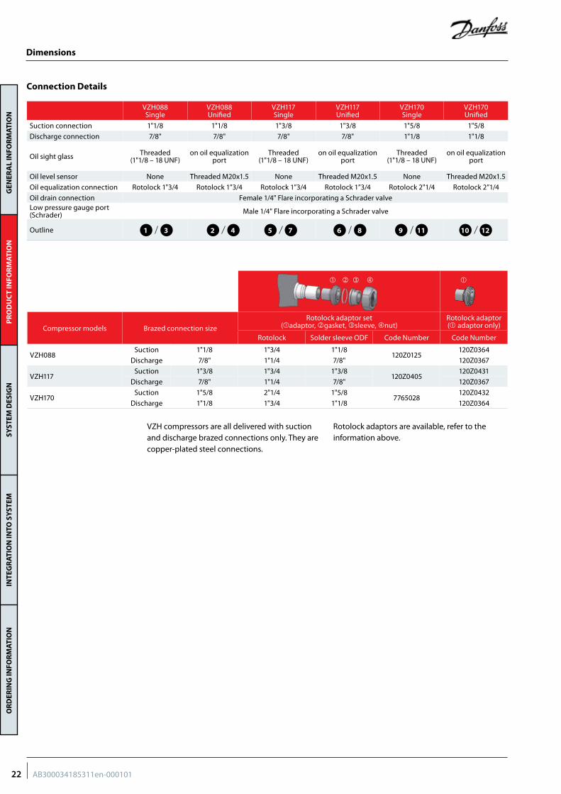
Compressor models Brazed connection sizeRotolock adaptor set
(adaptor, gasket, sleeve, nut)Rotolock adaptor( adaptor only)
Rotolock Solder sleeve ODF Code Number Code Number
VZH088Suction 1"1/8 1"3/4 1"1/8
120Z0125120Z0364
Discharge 7/8" 1"1/4 7/8" 120Z0367
VZH117Suction 1"3/8 1"3/4 1"3/8
120Z0405120Z0431
Discharge 7/8" 1"1/4 7/8" 120Z0367
VZH170Suction 1"5/8 2"1/4 1"5/8
7765028120Z0432
Discharge 1"1/8 1"3/4 1"1/8 120Z0364
VZH compressors are all delivered with suction and discharge brazed connections only. They are copper-plated steel connections.
Rotolock adaptors are available, refer to the information above.
Connection Details
VZH088 Single
VZH088 Unified
VZH117 Single
VZH117 Unified
VZH170 Single
VZH170 Unified
Suction connection 1"1/8 1"1/8 1"3/8 1"3/8 1"5/8 1"5/8
Discharge connection 7/8" 7/8" 7/8" 7/8" 1"1/8 1"1/8
Oil sight glass Threaded (1"1/8 – 18 UNF)
on oil equalization port
Threaded (1"1/8 – 18 UNF)
on oil equalization port
Threaded (1"1/8 – 18 UNF)
on oil equalization port
Oil level sensor None Threaded M20x1.5 None Threaded M20x1.5 None Threaded M20x1.5
Oil equalization connection Rotolock 1"3/4 Rotolock 1”3/4 Rotolock 1”3/4 Rotolock 1”3/4 Rotolock 2"1/4 Rotolock 2”1/4
Oil drain connection Female 1/4" Flare incorporating a Schrader valveLow pressure gauge port (Schrader) Male 1/4" Flare incorporating a Schrader valve
Outline 1 2 5 6 9 103 4 7 8 11 12
22 AB300034185311en-000101
GEN
ERA
L IN
FOR
MAT
ION
PR
OD
UC
T IN
FOR
MAT
ION
SYST
EM D
ESIG
NIN
TEG
RAT
ION
INTO
SY
STEM
OR
DER
ING
INFO
RM
ATIO
N
Dimensions
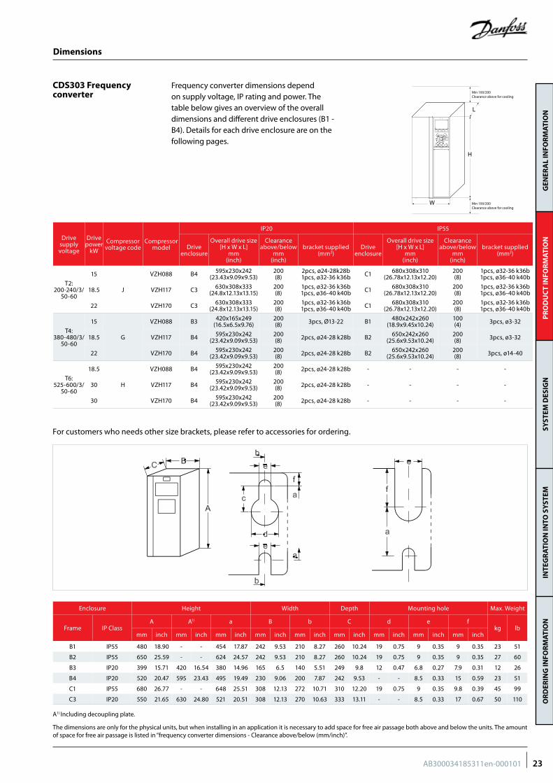
CDS303 Frequency converter
L
H
W Min 100/200Clearance above for cooling
Min 100/200Clearance above for cooling
Frequency converter dimensions depend on supply voltage, IP rating and power. The table below gives an overview of the overall dimensions and different drive enclosures (B1 - B4). Details for each drive enclosure are on the following pages.
Enclosure Height Width Depth Mounting hole Max. Weight
Frame IP ClassA A1) a B b C d e f
kg lbmm inch mm inch mm inch mm inch mm inch mm inch mm inch mm inch mm inch
B1 IP55 480 18.90 - - 454 17.87 242 9.53 210 8.27 260 10.24 19 0.75 9 0.35 9 0.35 23 51
B2 IP55 650 25.59 - - 624 24.57 242 9.53 210 8.27 260 10.24 19 0.75 9 0.35 9 0.35 27 60
B3 IP20 399 15.71 420 16.54 380 14.96 165 6.5 140 5.51 249 9.8 12 0.47 6.8 0.27 7.9 0.31 12 26
B4 IP20 520 20.47 595 23.43 495 19.49 230 9.06 200 7.87 242 9.53 - - 8.5 0.33 15 0.59 23 51
C1 IP55 680 26.77 - - 648 25.51 308 12.13 272 10.71 310 12.20 19 0.75 9 0.35 9.8 0.39 45 99
C3 IP20 550 21.65 630 24.80 521 20.51 308 12.13 270 10.63 333 13.11 - - 8.5 0.33 17 0.67 50 110
A1) Including decoupling plate.
The dimensions are only for the physical units, but when installing in an application it is necessary to add space for free air passage both above and below the units. The amount of space for free air passage is listed in “frequency converter dimensions - Clearance above/below (mm/inch)”.
Drive supply voltage
Drive power
kW
Compressor voltage code
Compressor model
IP20 IP55
Drive enclosure
Overall drive size [H x W x L]
mm (inch)
Clearance above/below
mm (inch)
bracket supplied(mm2)
Drive enclosure
Overall drive size[H x W x L]
mm (inch)
Clearance above/below
mm (inch)
bracket supplied(mm2)
T2: 200-240/3/
50-60
15
J
VZH088 B4 595x230x242(23.43x9.09x9.53)
200(8)
2pcs, ø24-28k28b1pcs, ø32-36 k36b C1 680x308x310
(26.78x12.13x12.20)200(8)
1pcs, ø32-36 k36b1pcs, ø36-40 k40b
18.5 VZH117 C3 630x308x333(24.8x12.13x13.15)
200(8)
1pcs, ø32-36 k36b1pcs, ø36-40 k40b C1 680x308x310
(26.78x12.13x12.20)200(8)
1pcs, ø32-36 k36b1pcs, ø36-40 k40b
22 VZH170 C3 630x308x333(24.8x12.13x13.15)
200(8)
1pcs, ø32-36 k36b1pcs, ø36-40 k40b C1 680x308x310
(26.78x12.13x12.20)200(8)
1pcs, ø32-36 k36b1pcs, ø36-40 k40b
T4: 380-480/3/
50-60
15
G
VZH088 B3 420x165x249(16.5x6.5x9.76)
200(8) 3pcs, Ø13-22 B1 480x242x260
(18.9x9.45x10.24)100 (4) 3pcs, ø3-32
18.5 VZH117 B4 595x230x242(23.42x9.09x9.53)
200(8) 2pcs, ø24-28 k28b B2 650x242x260
(25.6x9.53x10.24)200(8) 3pcs, ø3-32
22 VZH170 B4 595x230x242(23.42x9.09x9.53)
200(8) 2pcs, ø24-28 k28b B2 650x242x260
(25.6x9.53x10.24)200(8) 3pcs, ø14-40
T6: 525-600/3/
50-60
18.5
H
VZH088 B4 595x230x242(23.42x9.09x9.53)
200(8) 2pcs, ø24-28 k28b - - - -
30 VZH117 B4 595x230x242(23.42x9.09x9.53)
200(8) 2pcs, ø24-28 k28b - - - -
30 VZH170 B4 595x230x242(23.42x9.09x9.53)
200(8) 2pcs, ø24-28 k28b - - - -
For customers who needs other size brackets, please refer to accessories for ordering.
23AB300034185311en-000101
GEN
ERA
L IN
FOR
MAT
ION
PR
OD
UC
T IN
FOR
MAT
ION
SYST
EM D
ESIG
NIN
TEG
RAT
ION
INTO
SY
STEM
OR
DER
ING
INFO
RM
ATIO
N
Electrical data, connections and wiring
Compressor electrical specifications
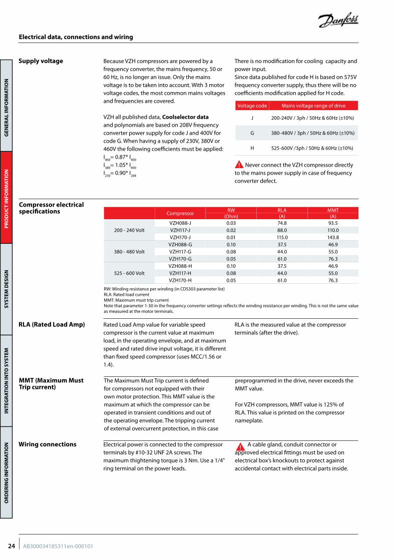
Because VZH compressors are powered by a frequency converter, the mains frequency, 50 or 60 Hz, is no longer an issue. Only the mains voltage is to be taken into account. With 3 motor voltage codes, the most common mains voltages and frequencies are covered.
VZH all published data, Coolselector data and polynomials are based on 208V frequency converter power supply for code J and 400V for code G. When having a supply of 230V, 380V or 460V the following coefficients must be applied:I460
= 0.87* I400
I380
= 1.05* I400
I230
= 0.90* I208
There is no modification for cooling capacity and power input.Since data published for code H is based on 575V frequency converter supply, thus there will be no coefficients modification applied for H code.
Never connect the VZH compressor directly to the mains power supply in case of frequency converter defect.
Supply voltage
Voltage code Mains voltage range of drive
J 200-240V / 3ph / 50Hz & 60Hz (±10%)
G 380-480V / 3ph / 50Hz & 60Hz (±10%)
H 525-600V /3ph / 50Hz & 60Hz (±10%)
Rated Load Amp value for variable speed compressor is the current value at maximum load, in the operating envelope, and at maximum speed and rated drive input voltage, it is different than fixed speed compressor (uses MCC/1.56 or 1.4).
RLA is the measured value at the compressor terminals (after the drive).
RLA (Rated Load Amp)
MMT (Maximum Must Trip current)
Wiring connections
The Maximum Must Trip current is defined for compressors not equipped with their own motor protection. This MMT value is the maximum at which the compressor can be operated in transient conditions and out of the operating envelope. The tripping current of external overcurrent protection, in this case
preprogrammed in the drive, never exceeds the MMT value.
For VZH compressors, MMT value is 125% of RLA. This value is printed on the compressor nameplate.
Electrical power is connected to the compressor terminals by #10-32 UNF 2A screws. The maximum thightening torque is 3 Nm. Use a 1/4" ring terminal on the power leads.
A cable gland, conduit connector or approved electrical fittings must be used on electrical box’s knockouts to protect against accidental contact with electrical parts inside.
CompressorRW RLA MMT
(Ohm) (A) (A)
200 - 240 VoltVZH088-J 0.03 74.8 93.5VZH117-J 0.02 88.0 110.0VZH170-J 0.01 115.0 143.8
380 - 480 VoltVZH088-G 0.10 37.5 46.9VZH117-G 0.08 44.0 55.0VZH170-G 0.05 61.0 76.3
525 - 600 VoltVZH088-H 0.10 37.5 46.9VZH117-H 0.08 44.0 55.0VZH170-H 0.05 61.0 76.3
RW: Winding resistance per winding (in CDS303 parameter list)RLA: Rated load currentMMT: Maximum must trip currentNote that parameter 1-30 in the frequency converter settings reflects the winding resistance per winding. This is not the same value as measured at the motor terminals.
24 AB300034185311en-000101
GEN
ERA
L IN
FOR
MAT
ION
PR
OD
UC
T IN
FOR
MAT
ION
SYST
EM D
ESIG
NIN
TEG
RAT
ION
INTO
SY
STEM
OR
DER
ING
INFO
RM
ATIO
N
Electrical data, connections and wiring
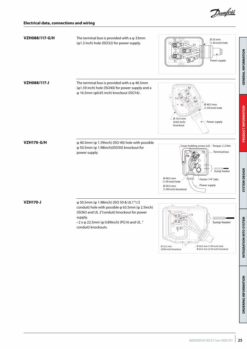
VZH088/117-J
VZH170-G/H
VZH170-J
The terminal box is provided with a φ 40.5mm (φ1.59 inch) hole (ISO40) for power supply and a φ 16.5mm (φ0.65 inch) knockout (ISO16) .
φ 40.5mm (φ 1.59inch) (ISO 40) hole with possible φ 50.5mm (φ 1.98inch)(ISO50) knockout for power supply
φ 50.5mm (φ 1.98inch) (ISO 50 & UL1”1/2conduit) hole with possible φ 63.5mm (φ 2.5inch) (ISO63 and UL 2”conduit) knockout for power supply.• 2 x φ 22.5mm (φ 0.89inch) (PG16 and UL .”conduit) knockouts.
VZH088/117-G/H The terminal box is provided with a φ 33mm (φ1.3 inch) hole (ISO32) for power supply.
Ø 33 mm (1.30 inch) hole
T2
T1
T3
Power supply
Ø 40.5 mm(1.59 inch) hole
Ø 16.5 mm(0.65 inch) knockout
Power supply
T2
T1
T3
Cover holding screw (x2) - Torque: 2.2 Nm
Faston 1/4" tabs
Terminal box
Power supply
Sump heater
Ø 40.5 mm(1.59 inch) hole
Ø 50.5 mm(1.99 inch) knockout
T1 T2T3T3
Ø 50.5 mm (1.99 inch) holeØ 63.5 mm (2.50 inch) knockout
T1
T2
T3
Ø 22.5 mm(0.89 inch) knockout
Sump heater
25AB300034185311en-000101
GEN
ERA
L IN
FOR
MAT
ION
PR
OD
UC
T IN
FOR
MAT
ION
SYST
EM D
ESIG
NIN
TEG
RAT
ION
INTO
SY
STEM
OR
DER
ING
INFO
RM
ATIO
N
Electrical data, connections and wiring
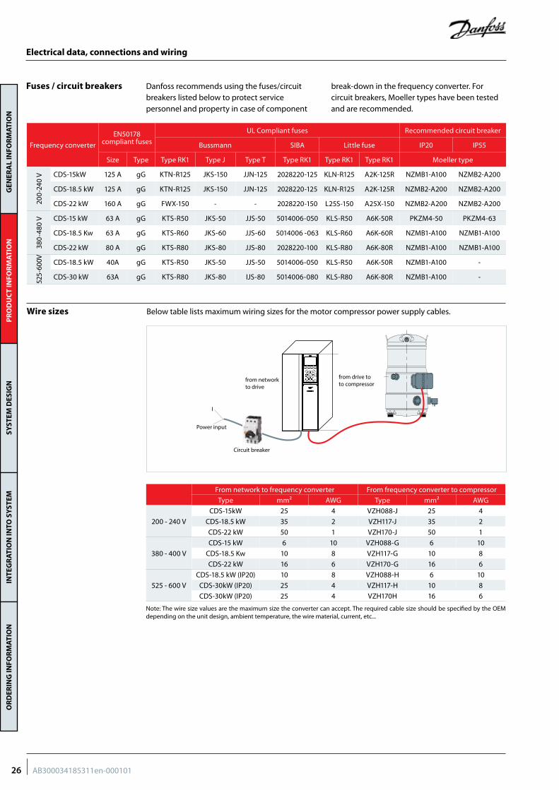
Wire sizes Below table lists maximum wiring sizes for the motor compressor power supply cables.
from networkto drive
from drive toto compressor
Circuit breaker
Power input
I
Fuses / circuit breakers
Frequency converter
EN50178 compliant fuses
UL Compliant fuses Recommended circuit breaker
Bussmann SIBA Little fuse IP20 IP55
Size Type Type RK1 Type J Type T Type RK1 Type RK1 Type RK1 Moeller type
200-
240
V CDS-15kW 125 A gG KTN-R125 JKS-150 JJN-125 2028220-125 KLN-R125 A2K-125R NZMB1-A100 NZMB2-A200
CDS-18.5 kW 125 A gG KTN-R125 JKS-150 JJN-125 2028220-125 KLN-R125 A2K-125R NZMB2-A200 NZMB2-A200
CDS-22 kW 160 A gG FWX-150 - - 2028220-150 L25S-150 A25X-150 NZMB2-A200 NZMB2-A200
380-
480
V CDS-15 kW 63 A gG KTS-R50 JKS-50 JJS-50 5014006-050 KLS-R50 A6K-50R PKZM4-50 PKZM4-63
CDS-18.5 Kw 63 A gG KTS-R60 JKS-60 JJS-60 5014006 -063 KLS-R60 A6K-60R NZMB1-A100 NZMB1-A100
CDS-22 kW 80 A gG KTS-R80 JKS-80 JJS-80 2028220-100 KLS-R80 A6K-80R NZMB1-A100 NZMB1-A100
525-
600V CDS-18.5 kW 40A gG KTS-R50 JKS-50 JJS-50 5014006-050 KLS-R50 A6K-50R NZMB1-A100 -
CDS-30 kW 63A gG KTS-R80 JKS-80 IJS-80 5014006-080 KLS-R80 A6K-80R NZMB1-A100 -
Danfoss recommends using the fuses/circuit breakers listed below to protect service personnel and property in case of component
break-down in the frequency converter. For circuit breakers, Moeller types have been tested and are recommended.
From network to frequency converter From frequency converter to compressor
Type mm² AWG Type mm² AWG
200 - 240 V
CDS-15kW 25 4 VZH088-J 25 4
CDS-18.5 kW 35 2 VZH117-J 35 2
CDS-22 kW 50 1 VZH170-J 50 1
380 - 400 V
CDS-15 kW 6 10 VZH088-G 6 10
CDS-18.5 Kw 10 8 VZH117-G 10 8
CDS-22 kW 16 6 VZH170-G 16 6
525 - 600 V
CDS-18.5 kW (IP20) 10 8 VZH088-H 6 10
CDS-30kW (IP20) 25 4 VZH117-H 10 8
CDS-30kW (IP20) 25 4 VZH170H 16 6
Note: The wire size values are the maximum size the converter can accept. The required cable size should be specified by the OEM depending on the unit design, ambient temperature, the wire material, current, etc...
26 AB300034185311en-000101
GEN
ERA
L IN
FOR
MAT
ION
PR
OD
UC
T IN
FOR
MAT
ION
SYST
EM D
ESIG
NIN
TEG
RAT
ION
INTO
SY
STEM
OR
DER
ING
INFO
RM
ATIO
N
Electrical data, connections and wiring
The CDS303 frequency converter generates by design a compressor soft start.
Current inrush will not exceed the frequency converter maximum current.
Basically seen from the mains, the inrush peak reach a level which is only a few percent more than the rated nominal current.
Soft-start control
The compressor will only operate properly in a single direction. If electrical connections are done correctly between the drive and the compressor terminals (compressor T1/T2/T3 and drive terminals U, V & W matching), the drive will provide correct phase supply to the compressor, and reverse rotation will be not possible:
• CDS terminal U (96) to VZH terminal T1• CDS terminal V (97) to VZH terminal T2• CDS terminal W (98) to VZH terminal T3
If compressor T1/T2/T3 and drive U, V & W terminals are not matching, the compressor can operate in a reverse rotation. This results in excessive noise and no pressure differential
between suction and discharge, and suction line warming rather than immediate cooling. (damage is in seconds, very little temp delta can be measured….no value to statement). The compressor can be rapidly damaged in these conditions. Reverse rotation of the compressor for only a few seconds can quickly cause irreversible damage to the scroll sets. Before starting always review the wiring and be prepared to shutoff immediately in case of noise. If reverse rotation symptoms occur, shut the compressor down and connect the phases to their proper terminals. Allow the compressor to run and then check amps at operating condition versus Danfoss published performance data to see if there was damage.
Phase sequence and reverse rotation protection
27AB300034185311en-000101
GEN
ERA
L IN
FOR
MAT
ION
PR
OD
UC
T IN
FOR
MAT
ION
SYST
EM D
ESIG
NIN
TEG
RAT
ION
INTO
SY
STEM
OR
DER
ING
INFO
RM
ATIO
N
Sound level and acoustic hood
ModelFrequency
RPS
200V 400V 575V
Without accoustic hood (dBA)
Acoustic hood code
Without accoustic hood (dBA)
Acoustic hood code
Without accoustic hood (dBA)
Acoustic hood code
VZH088
30 71120Z0510
(single version)120Z0512 (unified
version)
71120Z0509 (single
version)120Z0511 (unified
version)
72120Z0509 (single
version)120Z0511 (unified
version)
60 79 80 80
90 89 88 88
VZH117
30 73120Z0514
(single version)120Z0516
(unified version)
72120Z0513 (single
version)120Z0515 (unified
version)
71120Z0513 (single
version)120Z0515 (unified
version)
60 83 82 82
90 93 90 91
VZH170
30 78120Z0519 (single
version)120Z0520
(unified version)
77 120Z0517 (single version)
120Z0518 (unified version)
79120Z0517 (single
version)120Z0518 (unified
version)
60 89 87 88
90 95 94 94
Average sound power for reference at ARI A/C (7.2 °C/54.4 °C/11.1 °C/8.3 °C) (45 °F/130 °F/20 °F/15 °F) conditions measured in free space.*:With acoustic hood in the table, acoustic can decrease 5~7dBA
28 AB300034185311en-000101
GEN
ERA
L IN
FOR
MAT
ION
PR
OD
UC
T IN
FOR
MAT
ION
SYST
EM D
ESIG
NIN
TEG
RAT
ION
INTO
SY
STEM
OR
DER
ING
INFO
RM
ATIO
N
Electrical data, connections and wiring
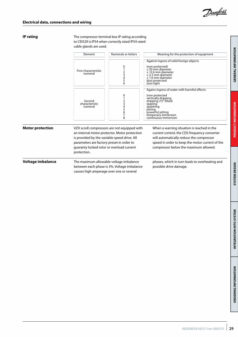
The compressor terminal box IP rating according to CEI529 is IP54 when correctly sized IP54 rated cable glands are used.
IP rating
Element Numerals or letters Meaning for the protection of equipment
First characteristic numeral
0123456
Against ingress of solid foreign objects
(non protected)≥ 50 mm diameter≥ 12.6 mm diameter≥ 2.5 mm diameter≥ 1.0 mm diameterdust protecteddust tight
Second characteristic
numeral
012345678
Agains ingress of water with harmful effects
(non protectedvertically drippingdripping (15° tilted)spayingsplashingjettingpowerful jettingtemporary immersioncontinuous immersion
VZH scroll compressors are not equipped with an internal motor protector. Motor protection is provided by the variable speed drive. All parameters are factory preset in order to guaranty locked rotor or overload current protection.
When a warning situation is reached in the current control, the CDS frequency converter will automatically reduce the compressor speed in order to keep the motor current of the compressor below the maximum allowed.
Motor protection
The maximum allowable voltage imbalance between each phase is 3%. Voltage imbalance causes high amperage over one or several
phases, which in turn leads to overheating and possible drive damage.
Voltage imbalance
29AB300034185311en-000101
GEN
ERA
L IN
FOR
MAT
ION
PR
OD
UC
T IN
FOR
MAT
ION
SYST
EM D
ESIG
NIN
TEG
RAT
ION
INTO
SY
STEM
OR
DER
ING
INFO
RM
ATIO
N
Approval and certificates
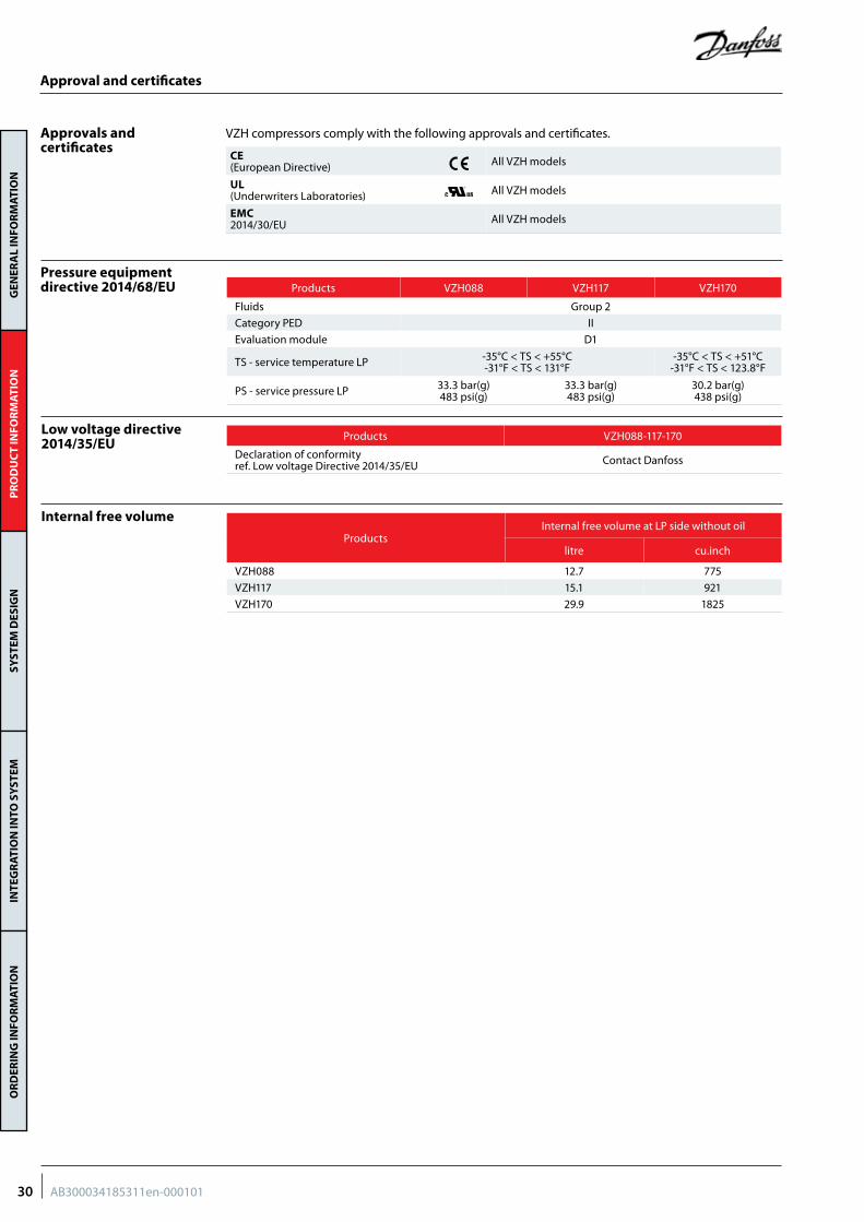
VZH compressors comply with the following approvals and certificates.Approvals and certificates
CE (European Directive) All VZH models
UL (Underwriters Laboratories) All VZH models
EMC2014/30/EU All VZH models
Pressure equipment directive 2014/68/EU
Low voltage directive 2014/35/EU
Internal free volume
ProductsInternal free volume at LP side without oil
litre cu.inch
VZH088 12.7 775
VZH117 15.1 921
VZH170 29.9 1825
Products VZH088 VZH117 VZH170
Fluids Group 2
Category PED II
Evaluation module D1
TS - service temperature LP -35°C < TS < +55°C-31°F < TS < 131°F
-35°C < TS < +51°C-31°F < TS < 123.8°F
PS - service pressure LP 33.3 bar(g)483 psi(g)
33.3 bar(g)483 psi(g)
30.2 bar(g)438 psi(g)
Products VZH088-117-170
Declaration of conformity ref. Low voltage Directive 2014/35/EU Contact Danfoss
30 AB300034185311en-000101
GEN
ERA
L IN
FOR
MAT
ION
PR
OD
UC
T IN
FOR
MAT
ION
SYST
EM D
ESIG
NIN
TEG
RAT
ION
INTO
SY
STEM
OR
DER
ING
INFO
RM
ATIO
N
System design generalities
Compressor capacity and modulation
Differences between variable speed and fix in speed unit design
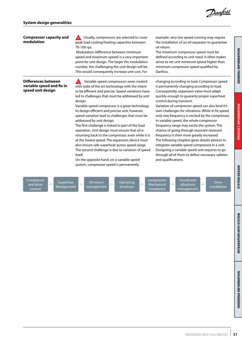
R Usually, compressors are selected to cover peak load cooling/heating capacities between 70-100 rps. Modulation (difference between minimum speed and maximum speed) is a very important point for unit design. The larger the modulation number, the challenging the unit design will be. This would consequently increase unit cost. For
example, very low speed running may require the installation of an oil separator to guarantee oil return.The minimum compressor speed must be defined according to unit need. It often makes sense to set unit minimum speed higher than minimum compressor speed qualified by Danfoss.
R Variable speed compressors were created with state of the art technology with the intent to be efficient and precise. Speed variations have led to challenges that must be addressed by unit design. Variable speed compressor is a great technology to design efficient and precise unit, however, speed variation lead to challenges that must be addressed by unit design.The first challenge is linked to part of the load operation. Unit design must ensure that oil is returning back to the compressor, even while it is at the lowest speed. The expansion device must also ensure safe superheat across speed range.The second challenge is due to variation of speed itself.On the opposite hand, on a variable speed system, compressor speed is permanently
changing according to load. Compressor speed is permanently changing according to load. Consequently, expansion valve must adapt quickly enough to guaranty proper superheat control during transient.Variation of compressor speed can also lend it’s own challenges for vibrations. While in fix speed, only one frequency is excited by the compressor. In variable speed, the whole compressor frequency range may excite the system. The chance of going through resonant resonant frequency is then more greatly increased. The following chapters gives details advices to integrate variable speed compressor in a unit. Designing a variable speed unit requires to go through all of them to define necessary safeties and qualifications.
Compressor and drive
control
Oil return management
Sound and vibrations
management
Superheat Management
compressor Mechanical installation
Operating envelope
Drive installation
31AB300034185311en-000101
GEN
ERA
L IN
FOR
MAT
ION
PR
OD
UC
T IN
FOR
MAT
ION
SYST
EM D
ESIG
NIN
TEG
RAT
ION
INTO
SY
STEM
OR
DER
ING
INFO
RM
ATIO
N
Oil injection control
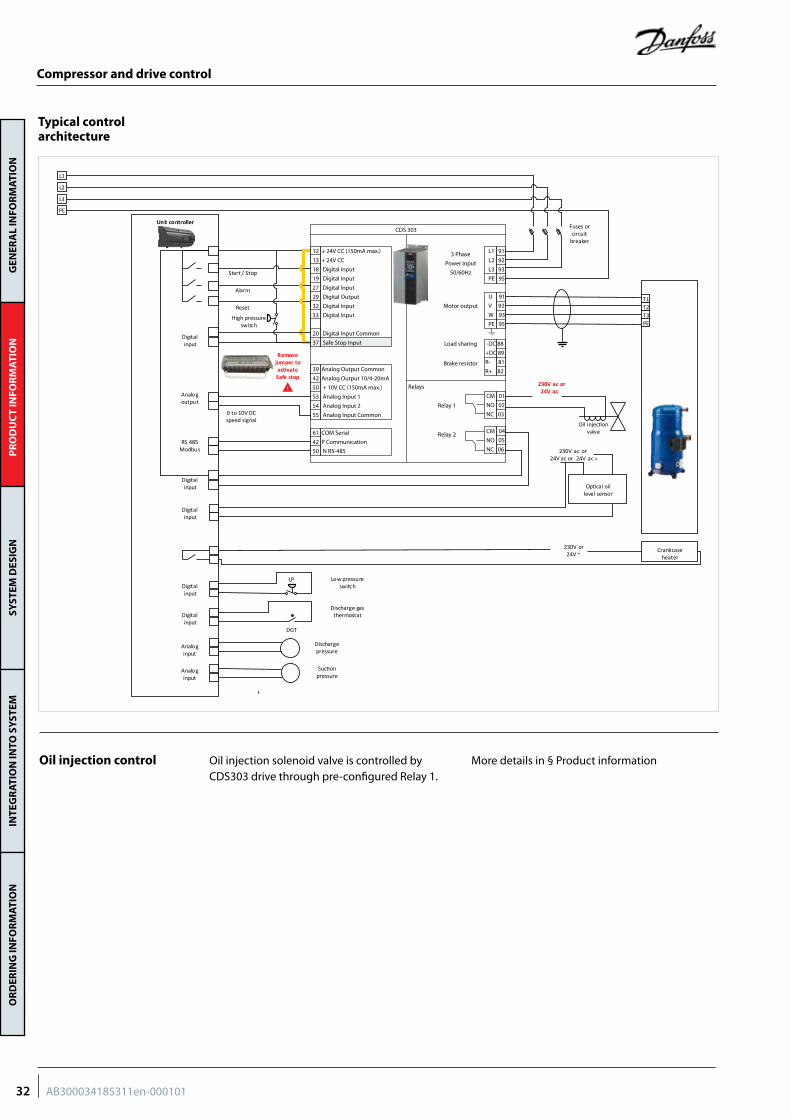
Typical control architecture
Oil injection solenoid valve is controlled by CDS303 drive through pre-configured Relay 1.
More details in § Product information
Compressor and drive control
230V ac or24V ac
Oil injec�on valve
230V or24V ~
Op�cal oil level sensor
Crankcase heater
230V ac or24V ac or 24V ac =
T1T2T3PE
L1
L2
L3
PE
Fuses or circuit
breaker
Digital input
Digital input
RS 485Modbus
Analog output
Start / Stop
Alarm
Reset
Remove jumper to ac�vate
Safe stop
LP
DGT
Discharge pressure
Suc�on pressure
Low pressure switch
Discharge gas thermostat
High pressure switch
Unit controller
0 to 10V DC speed signal
Digital input
Digital input
Analog input
Analog input
Digital input
12 + 24V CC (150mA max.)
13 + 24V CC
18 Digital Input
19 Digital Input
27 Digital Input
29 Digital Output
32 Digital Input
33 Digital Input
20 Digital Input Common
37 Safe Stop Input
L1 91
L2 92
L3 93
PE 95
CM 01
NO 02
NC 03
CM 04
NO 05
NC 06
-DC 88
+DC 89
R- 81
R+ 82
U 91
V 92
W 93
PE 95
3 Phase
Power input
50/60Hz
Motor output
Load sharing
Brake resistor
Relays
Relay 1
Relay 2
CDS 303
39 Analog Output Common
42 Analog Output 10/4-20mA
50 + 10V CC (150mA max.)
53 Analog Input 1
54 Analog Input 2
55 Analog Input Common
61 COM Serial
42 P Communication
50 N RS-485
!
32 AB300034185311en-000101
GEN
ERA
L IN
FOR
MAT
ION
PR
OD
UC
T IN
FOR
MAT
ION
SYST
EM D
ESIG
NIN
TEG
RAT
ION
INTO
SY
STEM
OR
DER
ING
INFO
RM
ATIO
N
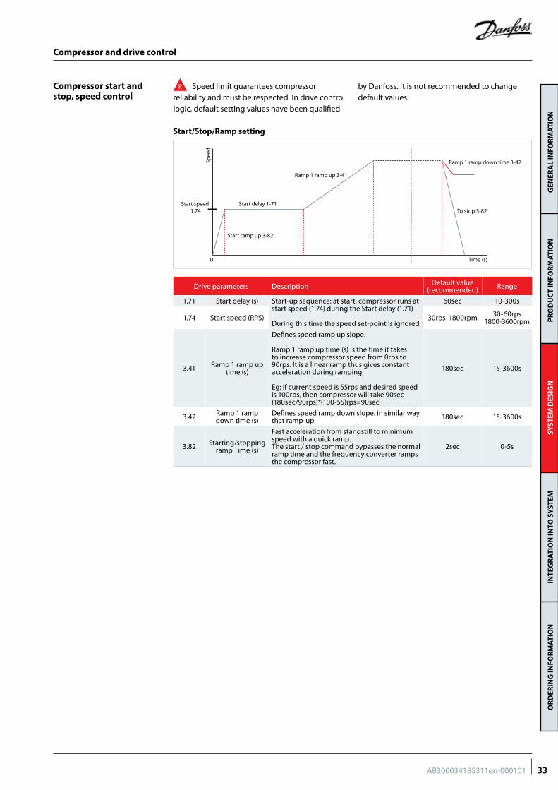
Compressor start and stop, speed control
Drive parameters Description Default value (recommended) Range
1.71 Start delay (s) Start-up sequence: at start, compressor runs at start speed (1.74) during the Start delay (1.71) During this time the speed set-point is ignored
60sec 10-300s
1.74 Start speed (RPS) 30rps 1800rpm 30-60rps1800-3600rpm
3.41 Ramp 1 ramp up time (s)
Defines speed ramp up slope. Ramp 1 ramp up time (s) is the time it takes to increase compressor speed from 0rps to 90rps. It is a linear ramp thus gives constant acceleration during ramping. Eg: if current speed is 55rps and desired speed is 100rps, then compressor will take 90sec (180sec/90rps)*(100-55)rps=90sec
180sec 15-3600s
3.42 Ramp 1 ramp down time (s)
Defines speed ramp down slope. in similar way that ramp-up. 180sec 15-3600s
3.82 Starting/stopping ramp Time (s)
Fast acceleration from standstill to minimum speed with a quick ramp. The start / stop command bypasses the normal ramp time and the frequency converter ramps the compressor fast.
2sec 0-5s
R Speed limit guarantees compressorreliability and must be respected. In drive control logic, default setting values have been qualified
by Danfoss. It is not recommended to change default values.
Start/Stop/Ramp setting
0 Time (s)
Start ramp up 3-82
Start speed 1.74
Spee
dTo stop 3-82
Ramp 1 ramp up 3-41
Ramp 1 ramp down time 3-42
Start delay 1-71
Compressor and drive control
33AB300034185311en-000101
GEN
ERA
L IN
FOR
MAT
ION
PR
OD
UC
T IN
FOR
MAT
ION
SYST
EM D
ESIG
NIN
TEG
RAT
ION
INTO
SY
STEM
OR
DER
ING
INFO
RM
ATIO
N
Interval between starts 300sec
(g) Start delay (W96)
(b) Compressor started
(c) Stop signal
(d) Stop delayed (W97)
(e) Compressor Stoped
(a) Start signal (f ) Start signal (i) Compressor Coast
(h) Compressor start
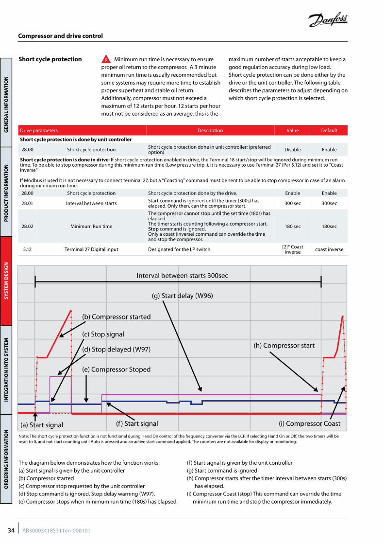
Drive parameters Description Value Default
Short cycle protection is done by unit controller
28.00 Short cycle protection Short cycle protection done in unit controller: (preferred option) Disable Enable
Short cycle protection is done in drive; If short cycle protection enabled in drive, the Terminal 18 start/stop will be ignored during minimum run time. To be able to stop compressor during this minimum run time (Low pressure trip..), it is necessary to use Terminal 27 (Par 5.12) and set it to “Coast inverse”
If Modbus is used it is not necessary to connect terminal 27, but a “Coasting” command must be sent to be able to stop compressor in case of an alarm during minimum run time.
28.00 Short cycle protection Short cycle protection done by the drive. Enable Enable
28.01 Interval between starts Start command is ignored until the timer (300s) has elapsed. Only then, can the compressor start. 300 sec 300sec
28.02 Minimum Run time
The compressor cannot stop until the set time (180s) has elapsed.The timer starts counting following a compressor start.Stop command is ignored.Only a coast (inverse) command can override the time and stop the compressor.
180 sec 180sec
5.12 Terminal 27 Digital input Designated for the LP switch. [2]* Coast inverse coast inverse
Short cycle protection R Minimum run time is necessary to ensure proper oil return to the compressor. A 3 minute minimum run time is usually recommended but some systems may require more time to establish proper superheat and stable oil return.Additionally, compressor must not exceed a maximum of 12 starts per hour. 12 starts per hour must not be considered as an average, this is the
maximum number of starts acceptable to keep a good regulation accuracy during low load.Short cycle protection can be done either by the drive or the unit controller. The following table describes the parameters to adjust depending on which short cycle protection is selected.
The diagram below demonstrates how the function works:(a) Start signal is given by the unit controller(b) Compressor started(c) Compressor stop requested by the unit controller(d) Stop command is ignored. Stop delay warning (W97).(e) Compressor stops when minimum run time (180s) has elapsed.
(f ) Start signal is given by the unit controller(g) Start command is ignored (h) Compressor starts after the timer interval between starts (300s)
has elapsed.(i) Compressor Coast (stop) This command can override the time
minimum run time and stop the compressor immediately.
Note: The short cycle protection function is not functional during Hand On control of the frequency converter via the LCP. If selecting Hand On or Off, the two timers will be reset to 0, and not start counting until Auto is pressed and an active start command applied. The counters are not available for display or monitoring.
Compressor and drive control
34 AB300034185311en-000101
GEN
ERA
L IN
FOR
MAT
ION
PR
OD
UC
T IN
FOR
MAT
ION
SYST
EM D
ESIG
NIN
TEG
RAT
ION
INTO
SY
STEM
OR
DER
ING
INFO
RM
ATIO
N
Drive alarm
Stop compressor in case of safeties (LP, HP, DGT)
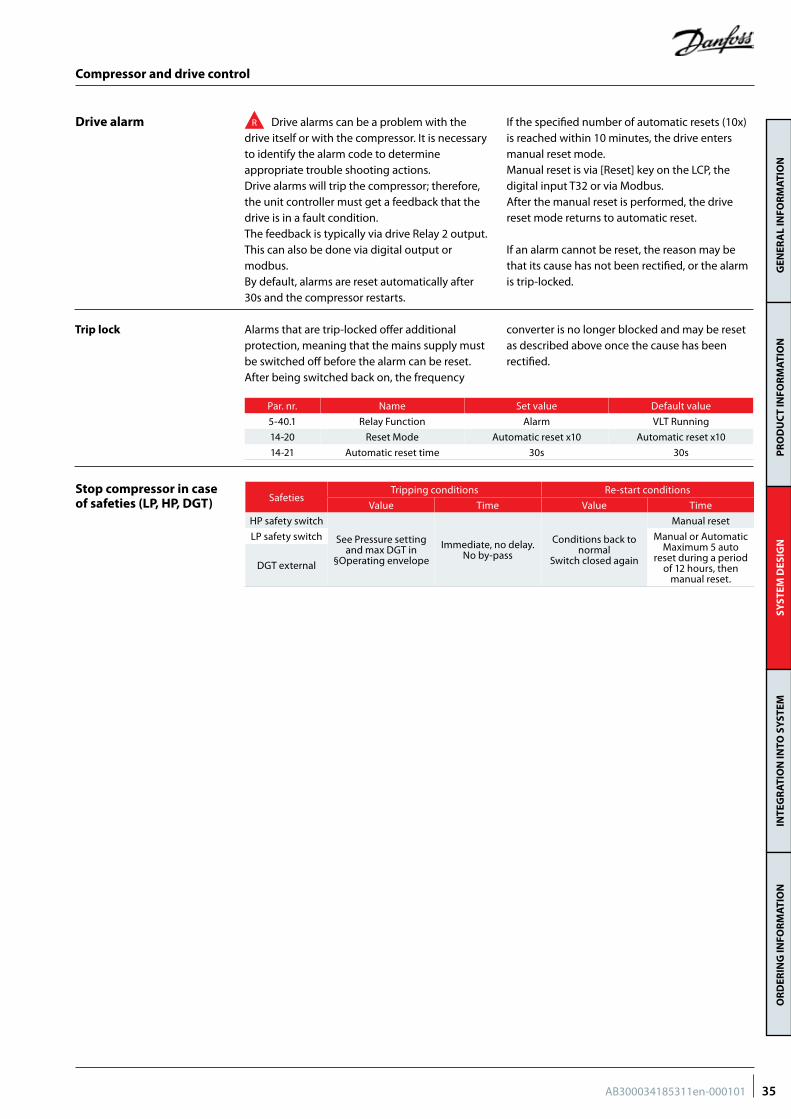
R Drive alarms can be a problem with the drive itself or with the compressor. It is necessary to identify the alarm code to determine appropriate trouble shooting actions.Drive alarms will trip the compressor; therefore, the unit controller must get a feedback that the drive is in a fault condition.The feedback is typically via drive Relay 2 output. This can also be done via digital output or modbus.By default, alarms are reset automatically after 30s and the compressor restarts.
If the specified number of automatic resets (10x) is reached within 10 minutes, the drive enters manual reset mode. Manual reset is via [Reset] key on the LCP, the digital input T32 or via Modbus.After the manual reset is performed, the drive reset mode returns to automatic reset.
If an alarm cannot be reset, the reason may be that its cause has not been rectified, or the alarm is trip-locked.
Alarms that are trip-locked offer additional protection, meaning that the mains supply must be switched off before the alarm can be reset. After being switched back on, the frequency
converter is no longer blocked and may be reset as described above once the cause has been rectified.
Trip lock
Par. nr. Name Set value Default value
5-40.1 Relay Function Alarm VLT Running
14-20 Reset Mode Automatic reset x10 Automatic reset x10
14-21 Automatic reset time 30s 30s
SafetiesTripping conditions Re-start conditions
Value Time Value Time
HP safety switch
See Pressure setting and max DGT in
§Operating envelope
Immediate, no delay.No by-pass
Conditions back to normal
Switch closed again
Manual reset
LP safety switch Manual or Automatic Maximum 5 auto
reset during a period of 12 hours, then
manual reset.DGT external
Compressor and drive control
35AB300034185311en-000101
GEN
ERA
L IN
FOR
MAT
ION
PR
OD
UC
T IN
FOR
MAT
ION
SYST
EM D
ESIG
NIN
TEG
RAT
ION
INTO
SY
STEM
OR
DER
ING
INFO
RM
ATIO
N
Compressor and drive control
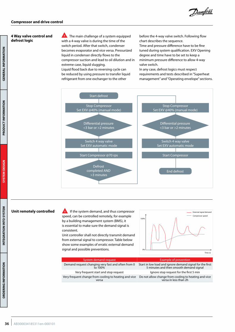
Unit remotely controlled R If the system demand, and thus compressor speed, can be controlled remotely, for example by a building management system (BMS), it is essential to make sure the demand signal is consistent.Unit controller shall not directly transmit demand from external signal to compressor. Table below show some examples of erratic external demand signal and possible preventions. 0%
Time (s)
100%
External signal demand
Compressor speed
System demand request Example of prevention
Demand request changing very fast and often from 0 to 100%
Start in low load and ignore demand signal for the first 5 minutes and then smooth demand signal
Very frequent start and stop request Ignore stop request for the first 5 min
Very frequent change from cooling to heating and vice versa
Do not allow change from cooling to heating and vice versa in less than 2h
Start defrost
Stop CompressorSet EXV @40% (manual mode)
Stop CompressorSet EXV @40% (manual mode)
Switch 4 way valveSet EXV automatic mode
Switch 4 way valveSet EXV automatic mode
Start Compressor @70 rps Start Compressor
Differential pressure<3 bar or >2 minutes
Differential pressure<3 bar or >2 minutes
Defrost completed AND
>3 minutesEnd defrost
4 Way valve control and defrost logic
R The main challenge of a system equipped with a 4-way valve is during the time of the switch period. After that switch, condenser becomes evaporator and vice versa. Pressurized liquid in condenser directly flows to the compressor suction and lead to oil dilution and in extreme case, liquid slugging.Liquid flood back due to reversing cycle can be reduced by using pressure to transfer liquid refrigerant from one exchanger to the other
before the 4-way valve switch. Following flow chart describes the sequence.Time and pressure difference have to be fine tuned during system qualification. EXV Opening degree and time have to be set to keep a minimum pressure difference to allow 4-way valve switch.In any case, defrost logics must respect requirements and tests described in “Superheat management” and “Operating envelope” sections.
36 AB300034185311en-000101
GEN
ERA
L IN
FOR
MAT
ION
PR
OD
UC
T IN
FOR
MAT
ION
SYST
EM D
ESIG
NIN
TEG
RAT
ION
INTO
SY
STEM
OR
DER
ING
INFO
RM
ATIO
N
Superheat management
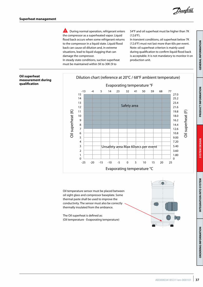
R During normal operation, refrigerant enters the compressor as a superheated vapor. Liquid flood back occurs when some refrigerant returns to the compressor in a liquid state. Liquid flood back can cause oil dilution and, in extreme situations, lead to liquid slugging that can damage the compressor.In steady state conditions, suction superheat must be maintained within 5K to 30K (9 to
54°F and oil superheat must be higher than 7K (12.6°F).In transient conditions, oil superheat below 7K (12.6°F) must not last more than 60s per event.Note: oil superheat criterion is mainly used during qualification to confirm liquid flood back is acceptable. It is not mandatory to monitor it on production unit.
Oil superheat measurement during qualification
-25012
3456789
101112131415
01.803.60
5.407.209.0010.812.614.416.218.019.821.623.425.227.0
-20 -15 -10 0 5 10 15 20 25
-13 -4 5 14
-5
23 32 41 50 59 68 77
Dilution chart (reference at 20°C / 68°F ambient temperature)
Evaporating temperature °C
Evaporating temperature °F
Safety area
Unsafety area Max 60secs per event
Oil
sup
erhe
at (K
)
Oil
sup
erhe
at (F
)Oil temperature sensor must be placed between oil sight glass and compressor baseplate. Some thermal paste shall be used to improve the conductivity. The sensor must also be correctly thermally insulated from the ambiance.
The Oil superheat is defined as:(Oil temperature - Evaporating temperature)
37AB300034185311en-000101
GEN
ERA
L IN
FOR
MAT
ION
PR
OD
UC
T IN
FOR
MAT
ION
SYST
EM D
ESIG
NIN
TEG
RAT
ION
INTO
SY
STEM
OR
DER
ING
INFO
RM
ATIO
N
Superheat management
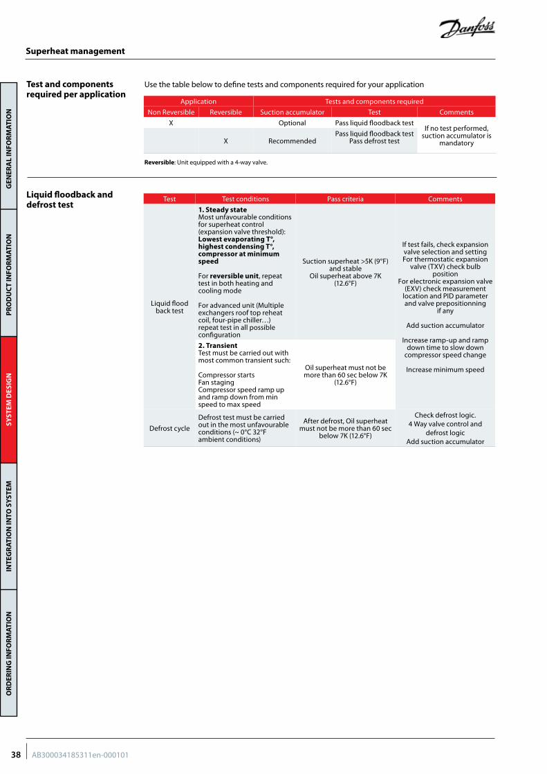
Test Test conditions Pass criteria Comments
Liquid flood back test
1. Steady stateMost unfavourable conditions for superheat control (expansion valve threshold):Lowest evaporating T°, highest condensing T°, compressor at minimum speed
For reversible unit, repeat test in both heating and cooling mode
For advanced unit (Multiple exchangers roof top reheat coil, four-pipe chiller…) repeat test in all possible configuration
Suction superheat >5K (9°F) and stable
Oil superheat above 7K (12.6°F)
If test fails, check expansion valve selection and setting For thermostatic expansion
valve (TXV) check bulb position
For electronic expansion valve (EXV) check measurement
location and PID parameter and valve prepositionning
if any
Add suction accumulator
Increase ramp-up and ramp down time to slow down
compressor speed change
Increase minimum speed
2. TransientTest must be carried out with most common transient such:
Compressor startsFan stagingCompressor speed ramp up and ramp down from min speed to max speed
Oil superheat must not be more than 60 sec below 7K
(12.6°F)
Defrost cycle
Defrost test must be carried out in the most unfavourable conditions (~ 0°C 32°F ambient conditions)
After defrost, Oil superheat must not be more than 60 sec
below 7K (12.6°F)
Check defrost logic.4 Way valve control and
defrost logicAdd suction accumulator
Liquid floodback and defrost test
Reversible: Unit equipped with a 4-way valve.
Use the table below to define tests and components required for your applicationTest and components required per application
Application Tests and components required
Non Reversible Reversible Suction accumulator Test Comments
X Optional Pass liquid floodback testIf no test performed,
suction accumulator is mandatoryX Recommended
Pass liquid floodback test Pass defrost test
38 AB300034185311en-000101
GEN
ERA
L IN
FOR
MAT
ION
PR
OD
UC
T IN
FOR
MAT
ION
SYST
EM D
ESIG
NIN
TEG
RAT
ION
INTO
SY
STEM
OR
DER
ING
INFO
RM
ATIO
N
Expansion valve
Selection of expansion valve
R Role of expansion device is to open and close to maintain a proper superheat at outlet of evaporator (s)
• Electronic expansion device (EXV) is preferred to thermostatic expansion device (TXV) as it has a better ability to control superheat at low load.
• It is essential that valve closes when compressor stops.
• For TXV, liquid line solenoid valve is strongly recommended, and if not possible, suction accumulator can be used as an alternative.
• Bleed type valve is not accepted. • For EXV, controller must be programmed to
close it when the compressor stops, including in power shut down situation.
• See § MOP (Max operating pressure control) in operating envelope section.
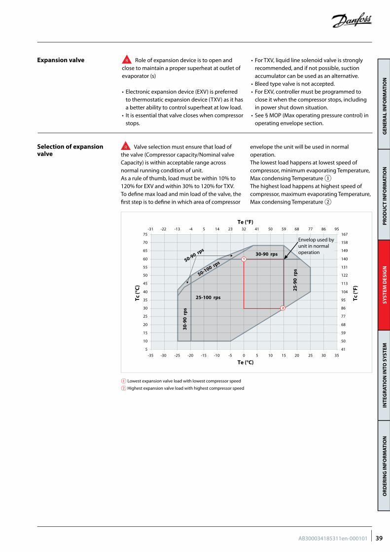
R Valve selection must ensure that load of the valve (Compressor capacity/Nominal valve Capacity) is within acceptable range across normal running condition of unit.As a rule of thumb, load must be within 10% to 120% for EXV and within 30% to 120% for TXV.To define max load and min load of the valve, the first step is to define in which area of compressor
envelope the unit will be used in normal operation.The lowest load happens at lowest speed of compressor, minimum evaporating Temperature, Max condensing Temperature ①The highest load happens at highest speed of compressor, maximum evaporating Temperature, Max condensing Temperature ②
5
15
10
25
20
35
30
45
40
50
55
60
65
70
75
41
59
50
77
68
95
86
113
104
122
131
140
149
158
167
Tc (°
C)
Tc (°
F)
30-9
0 r
ps
50-100 rps50-90 rps
25-100 rps25
-90
rp
s
Te (°C)
Te (°F)
-35 -30 -25 -20 -15 -10 -5 0 5 1510 30 352520
-31 -22 -13 -4 5 14 23 32 41 5950 86 957768
30-90 rps1
2
Envelop used by unit in normal operation
① Lowest expansion valve load with lowest compressor speed
② Highest expansion valve load with highest compressor speed
39AB300034185311en-000101
GEN
ERA
L IN
FOR
MAT
ION
PR
OD
UC
T IN
FOR
MAT
ION
SYST
EM D
ESIG
NIN
TEG
RAT
ION
INTO
SY
STEM
OR
DER
ING
INFO
RM
ATIO
N
Superheat management
Adjustment of exv control parameters
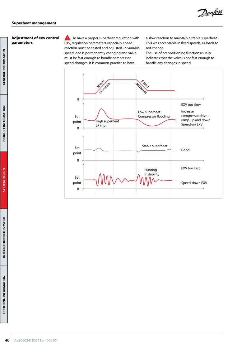
R To have a proper superheat regulation with EXV, regulation parameters especially speed reaction must be tested and adjusted. In variable speed load is permanently changing and valve must be fast enough to handle compressor speed changes. It is common practice to have
a slow reaction to maintain a stable superheat. This was acceptable in fixed speeds, as loads to not change.The use of prepositioning function usually indicates that the valve is not fast enough to handle any changes in speed.
0
Speeddecreases
Speed
increase
s
0
0
0
High superheatLP trip
Low superheatCompressor flooding
EXV too slow
EXV too Fast
Increase compressor drive ramp-up and down Speed-up EXV
Speed-down EXV
GoodStable superheat
Hunting Instability
Set
point
Set
point
Set
point
40 AB300034185311en-000101
GEN
ERA
L IN
FOR
MAT
ION
PR
OD
UC
T IN
FOR
MAT
ION
SYST
EM D
ESIG
NIN
TEG
RAT
ION
INTO
SY
STEM
OR
DER
ING
INFO
RM
ATIO
N
Location and installation of bulb (TXV) or pressure and temperature sensor (EXV)
Suction accumulator
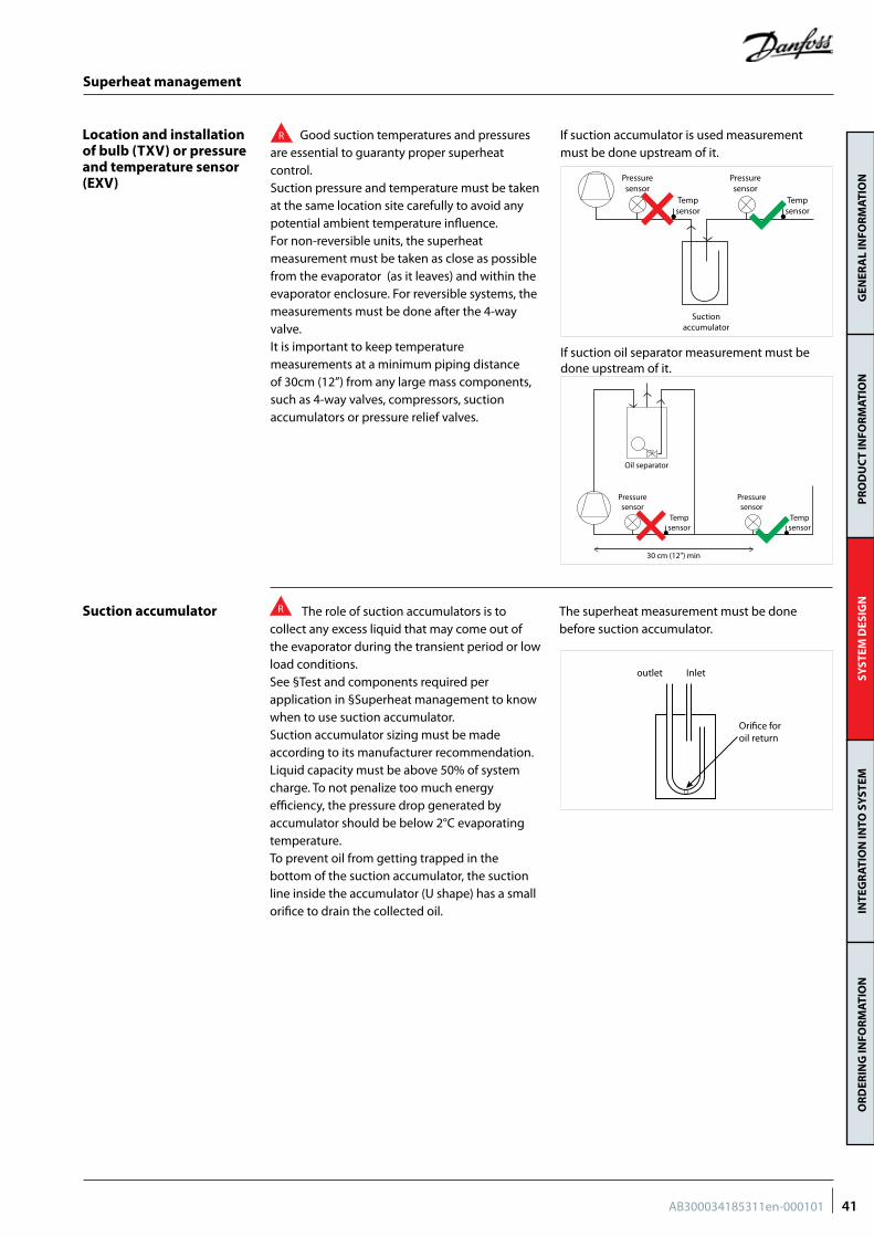
R Good suction temperatures and pressures are essential to guaranty proper superheat control.Suction pressure and temperature must be taken at the same location site carefully to avoid any potential ambient temperature influence. For non-reversible units, the superheat measurement must be taken as close as possible from the evaporator (as it leaves) and within the evaporator enclosure. For reversible systems, the measurements must be done after the 4-way valve.It is important to keep temperature measurements at a minimum piping distance of 30cm (12”) from any large mass components, such as 4-way valves, compressors, suction accumulators or pressure relief valves.
R The role of suction accumulators is to collect any excess liquid that may come out of the evaporator during the transient period or low load conditions. See §Test and components required per application in §Superheat management to know when to use suction accumulator.Suction accumulator sizing must be made according to its manufacturer recommendation. Liquid capacity must be above 50% of system charge. To not penalize too much energy efficiency, the pressure drop generated by accumulator should be below 2°C evaporating temperature.To prevent oil from getting trapped in the bottom of the suction accumulator, the suction line inside the accumulator (U shape) has a small orifice to drain the collected oil.
The superheat measurement must be done before suction accumulator.
Superheat management
Tempsensor
Tempsensor
Pressuresensor
Oil separator
30 cm (12”) min
Pressuresensor
Tempsensor
Tempsensor
Pressuresensor
Pressuresensor
Suctionaccumulator
If suction accumulator is used measurement must be done upstream of it.
If suction oil separator measurement must be done upstream of it.
Orifice foroil return
Inletoutlet
41AB300034185311en-000101
GEN
ERA
L IN
FOR
MAT
ION
PR
OD
UC
T IN
FOR
MAT
ION
SYST
EM D
ESIG
NIN
TEG
RAT
ION
INTO
SY
STEM
OR
DER
ING
INFO
RM
ATIO
N
Oil return management
Test and components required per application
Oil return test
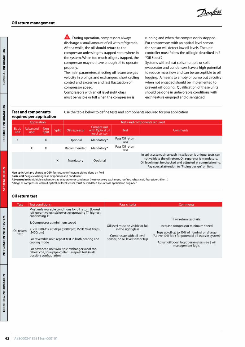
R During operation, compressors always discharge a small amount of oil with refrigerant. After a while, the oil should return to the compressor unless it gets trapped somewhere in the system. When too much oil gets trapped, the compressor may not have enough oil to operate properly.The main parameters affecting oil return are gas velocity in piping’s and exchangers, short cycling control and excessive and fast fluctuation of compressor speed.Compressors with an oil level sight glass must be visible or full when the compressor is
running and when the compressor is stopped. For compressors with an optical level sensor, the sensor will detect low oil levels. The unit controller must follow the oil logic described in § “Oil Boost”.Systems with reheat coils, multiple or split evaporator and condensers have a high potential to reduce mass flow and can be susceptible to oil logging. A means to empty or pump out circuitry when not engaged should be implemented to prevent oil logging. Qualification of these units should be done in unfavorable conditions with each feature engaged and disengaged.
Use the table below to define tests and components required for you application
Non split: Unit pre charge at OEM factory, no refrigerant piping done on fieldBasic unit: Single exchanger as evaporator and condenserAdvanced unit: Multiple exchangers as evaporator or condenser (heat-recovery exchanger, roof top reheat coil, four-pipe chiller…)*Usage of compressor without optical oil level sensor must be validated by Danfoss application engineer
Application Tests and components required
Basic unit
Advanced unit
Non Split Split Oil separator
Compressor with Optical oil
level sensorTest Comments
X X Optional Mandatory* Pass Oil return test
X X Recommended Mandatory* Pass Oil return test
X Mandatory Optional
In split system, since each installation is unique, tests can not validate the oil return, Oil separator is mandatory.
Oil level must be checked and adjusted at commissioning.Pay special attention to “Piping design” on field.
Test Test conditions Pass criteria Comments
Oil return test
Most unfavourable conditions for oil return (lowest refrigerant velocity): lowest evaporating T°, highest condensing T°
1. Compressor at minimum speed
2. VZH088-117 at 50rps (3000rpm) VZH170 at 40rps (2400rpm)
For reversible unit, repeat test in both heating and cooling mode
For advanced unit (Multiple exchangers roof top reheat coil, four-pipe chiller…) repeat test in all possible configuration
Oil level must be visible or full in the sight glass
Compressor with oil level sensor, no oil level sensor trip
If oil return test fails:
Increase compressor minimum speed
Tops up oil up to 10% of nominal oil charge (Above 10% look for potential oil traps in system)
Adjust oil boost logic parameters see § oil management logic
42 AB300034185311en-000101
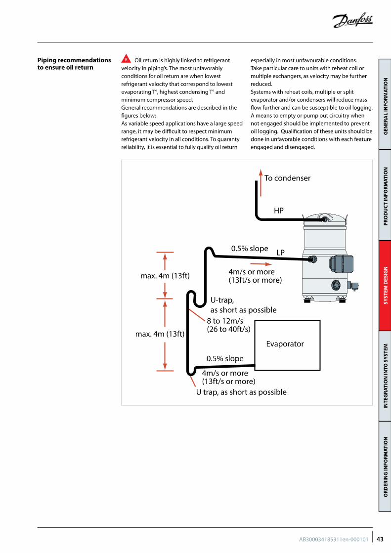
GEN
ERA
L IN
FOR
MAT
ION
PR
OD
UC
T IN
FOR
MAT
ION
SYST
EM D
ESIG
NIN
TEG
RAT
ION
INTO
SY
STEM
OR
DER
ING
INFO
RM
ATIO
N
Piping recommendations to ensure oil return
R Oil return is highly linked to refrigerant velocity in piping’s. The most unfavorably conditions for oil return are when lowest refrigerant velocity that correspond to lowest evaporating T°, highest condensing T° and minimum compressor speed.General recommendations are described in the figures below:As variable speed applications have a large speed range, it may be difficult to respect minimum refrigerant velocity in all conditions. To guaranty reliability, it is essential to fully qualify oil return
especially in most unfavourable conditions.Take particular care to units with reheat coil or multiple exchangers, as velocity may be further reduced.Systems with reheat coils, multiple or split evaporator and/or condensers will reduce mass flow further and can be susceptible to oil logging. A means to empty or pump out circuitry when not engaged should be implemented to prevent oil logging. Qualification of these units should be done in unfavorable conditions with each feature engaged and disengaged.
HP
4m/s or more(13ft/s or more)
0.5% slope
To condenser
max. 4m (13ft)
max. 4m (13ft)
0.5% slope
U-trap, as short as possible
4m/s or more(13ft/s or more)
U trap, as short as possible
Evaporator
LP
8 to 12m/s(26 to 40ft/s)
43AB300034185311en-000101
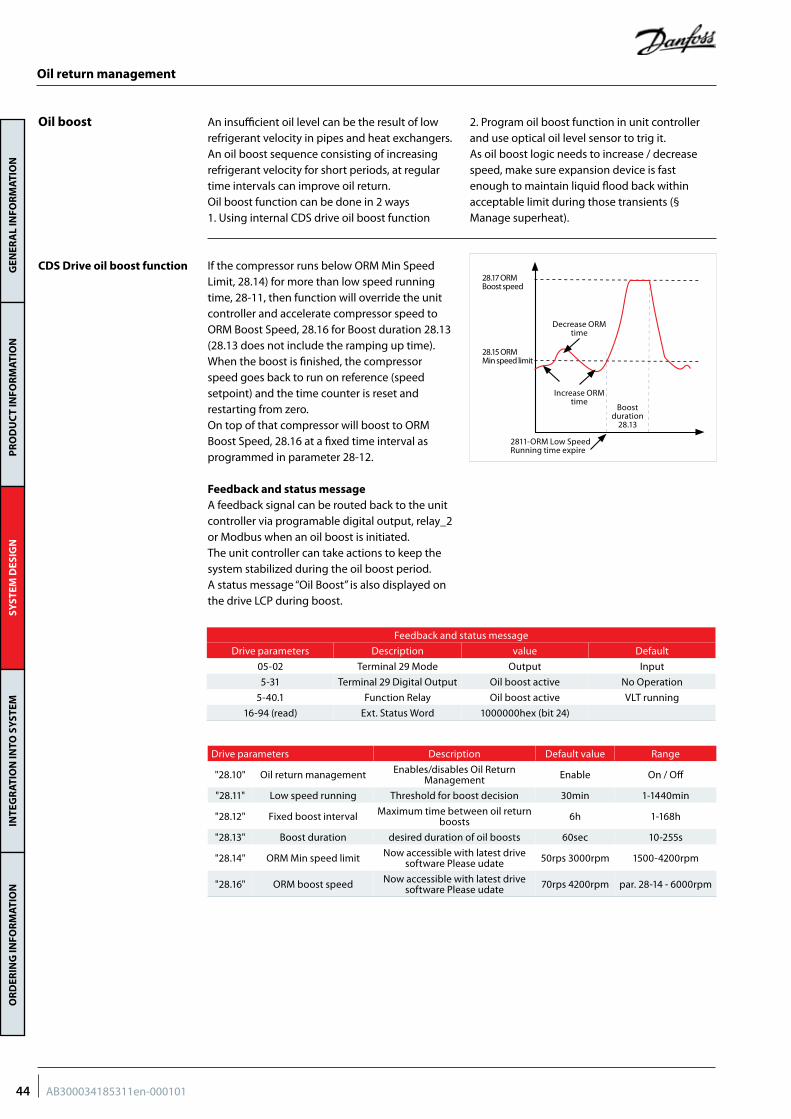
GEN
ERA
L IN
FOR
MAT
ION
PR
OD
UC
T IN
FOR
MAT
ION
SYST
EM D
ESIG
NIN
TEG
RAT
ION
INTO
SY
STEM
OR
DER
ING
INFO
RM
ATIO
N
An insufficient oil level can be the result of low refrigerant velocity in pipes and heat exchangers. An oil boost sequence consisting of increasing refrigerant velocity for short periods, at regular time intervals can improve oil return.Oil boost function can be done in 2 ways1. Using internal CDS drive oil boost function
2. Program oil boost function in unit controller and use optical oil level sensor to trig it.As oil boost logic needs to increase / decrease speed, make sure expansion device is fast enough to maintain liquid flood back within acceptable limit during those transients (§ Manage superheat).
If the compressor runs below ORM Min Speed Limit, 28.14) for more than low speed running time, 28-11, then function will override the unit controller and accelerate compressor speed to ORM Boost Speed, 28.16 for Boost duration 28.13 (28.13 does not include the ramping up time).When the boost is finished, the compressor speed goes back to run on reference (speed setpoint) and the time counter is reset and restarting from zero.On top of that compressor will boost to ORM Boost Speed, 28.16 at a fixed time interval as programmed in parameter 28-12.
Feedback and status messageA feedback signal can be routed back to the unit controller via programable digital output, relay_2 or Modbus when an oil boost is initiated.The unit controller can take actions to keep the system stabilized during the oil boost period. A status message “Oil Boost” is also displayed on the drive LCP during boost.
Oil return management
Oil boost
CDS Drive oil boost function28.17 ORMBoost speed
28.15 ORMMin speed limit
2811-ORM Low SpeedRunning time expire
Boost duration
28.13
Decrease ORMtime
Increase ORMtime
Feedback and status message
Drive parameters Description value Default
05-02 Terminal 29 Mode Output Input
5-31 Terminal 29 Digital Output Oil boost active No Operation
5-40.1 Function Relay Oil boost active VLT running
16-94 (read) Ext. Status Word 1000000hex (bit 24)
Drive parameters Description Default value Range
"28.10" Oil return management Enables/disables Oil Return Management Enable On / Off
"28.11" Low speed running Threshold for boost decision 30min 1-1440min
"28.12" Fixed boost interval Maximum time between oil return boosts 6h 1-168h
"28.13" Boost duration desired duration of oil boosts 60sec 10-255s
"28.14" ORM Min speed limit Now accessible with latest drive software Please udate 50rps 3000rpm 1500-4200rpm
"28.16" ORM boost speed Now accessible with latest drive software Please udate 70rps 4200rpm par. 28-14 - 6000rpm
44 AB300034185311en-000101
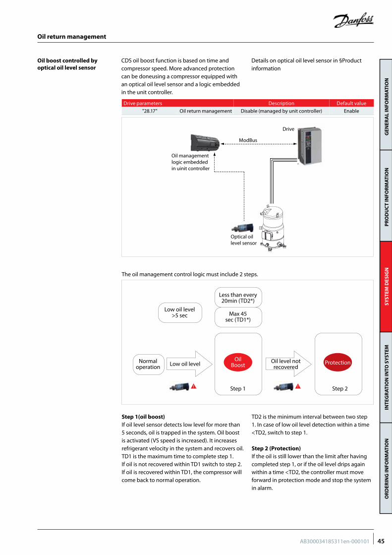
GEN
ERA
L IN
FOR
MAT
ION
PR
OD
UC
T IN
FOR
MAT
ION
SYST
EM D
ESIG
NIN
TEG
RAT
ION
INTO
SY
STEM
OR
DER
ING
INFO
RM
ATIO
N
Step 1(oil boost)If oil level sensor detects low level for more than 5 seconds, oil is trapped in the system. Oil boost is activated (VS speed is increased). It increases refrigerant velocity in the system and recovers oil. TD1 is the maximum time to complete step 1. If oil is not recovered within TD1 switch to step 2.If oil is recovered within TD1, the compressor will come back to normal operation.
TD2 is the minimum interval between two step 1. In case of low oil level detection within a time <TD2, switch to step 1.
Step 2 (Protection)If the oil is still lower than the limit after having completed step 1, or if the oil level drips again within a time <TD2, the controller must move forward in protection mode and stop the system in alarm.
CDS oil boost function is based on time and compressor speed. More advanced protection can be doneusing a compressor equipped with an optical oil level sensor and a logic embedded in the unit controller.
Details on optical oil level sensor in §Product information
Oil return management
Oil boost controlled by optical oil level sensor
Drive parameters Description Default value
"28.17" Oil return management Disable (managed by unit controller) Enable
Normaloperation
Low oil level>5 sec
Low oil level Oil level notrecovered
Less than every20min (TD2*)
Max 45sec (TD1*)
OilBoost
Step 1 Step 2
Protection
The oil management control logic must include 2 steps.
ModBus
Oil management logic embedded in uinit controller
Drive
Optical oil level sensor
45AB300034185311en-000101
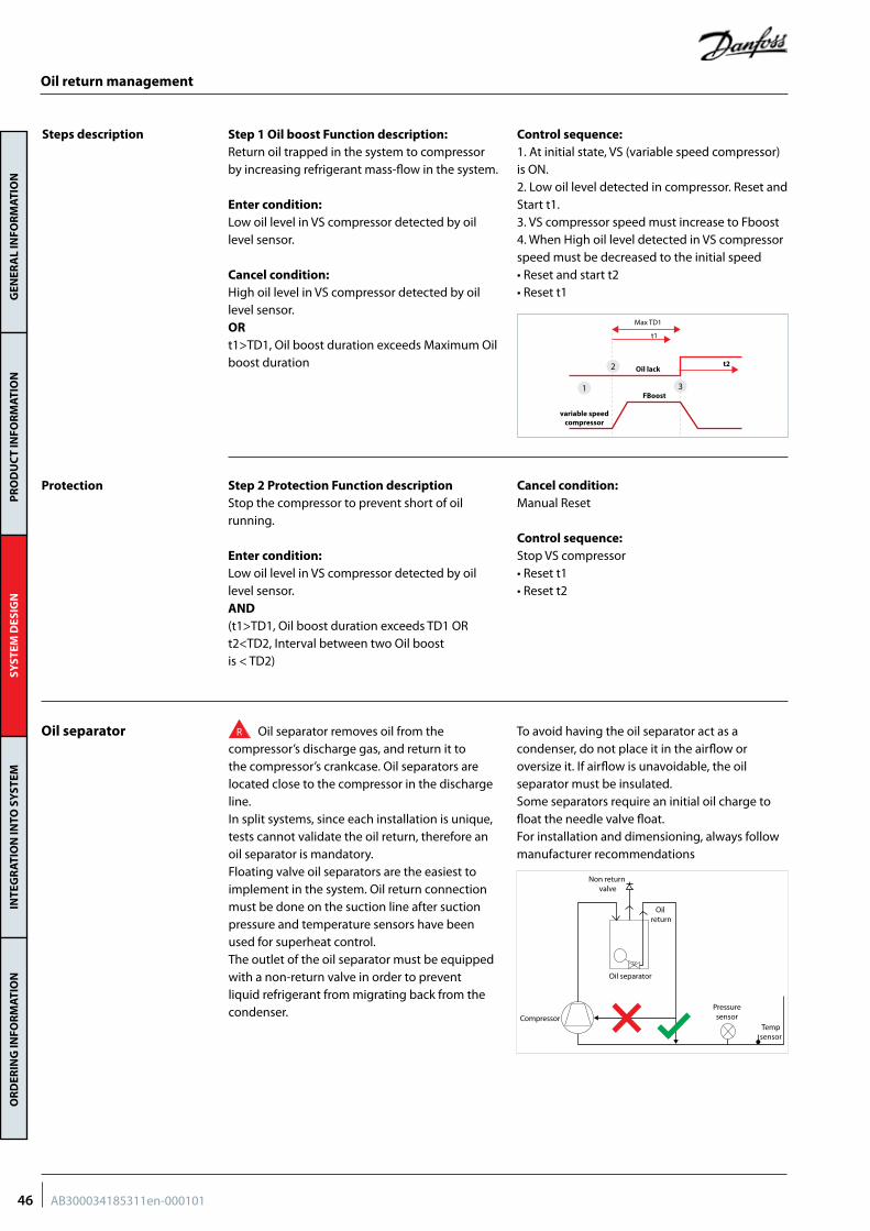
GEN
ERA
L IN
FOR
MAT
ION
PR
OD
UC
T IN
FOR
MAT
ION
SYST
EM D
ESIG
NIN
TEG
RAT
ION
INTO
SY
STEM
OR
DER
ING
INFO
RM
ATIO
N
Step 1 Oil boost Function description:Return oil trapped in the system to compressor by increasing refrigerant mass-flow in the system.
Enter condition:Low oil level in VS compressor detected by oil level sensor.
Cancel condition:High oil level in VS compressor detected by oil level sensor.ORt1>TD1, Oil boost duration exceeds Maximum Oilboost duration
Control sequence:1. At initial state, VS (variable speed compressor) is ON.2. Low oil level detected in compressor. Reset andStart t1.3. VS compressor speed must increase to Fboost4. When High oil level detected in VS compressor speed must be decreased to the initial speed• Reset and start t2• Reset t1
Step 2 Protection Function descriptionStop the compressor to prevent short of oil running.
Enter condition:Low oil level in VS compressor detected by oil level sensor.AND(t1>TD1, Oil boost duration exceeds TD1 ORt2<TD2, Interval between two Oil boostis < TD2)
Cancel condition:Manual Reset
Control sequence:Stop VS compressor• Reset t1• Reset t2
Steps description
Oil lack
Max TD1
t1
t2
variable speed compressor
FBoost3
2
1
Protection
Oil separator R Oil separator removes oil from the compressor’s discharge gas, and return it to the compressor’s crankcase. Oil separators are located close to the compressor in the discharge line.In split systems, since each installation is unique, tests cannot validate the oil return, therefore an oil separator is mandatory.Floating valve oil separators are the easiest to implement in the system. Oil return connection must be done on the suction line after suction pressure and temperature sensors have been used for superheat control.The outlet of the oil separator must be equipped with a non-return valve in order to prevent liquid refrigerant from migrating back from the condenser.
To avoid having the oil separator act as a condenser, do not place it in the airflow or oversize it. If airflow is unavoidable, the oil separator must be insulated.Some separators require an initial oil charge to float the needle valve float.For installation and dimensioning, always follow manufacturer recommendations
Tempsensor
Oil separator
Compressor
Oil return
Non return valve
Pressuresensor
Oil return management
46 AB300034185311en-000101
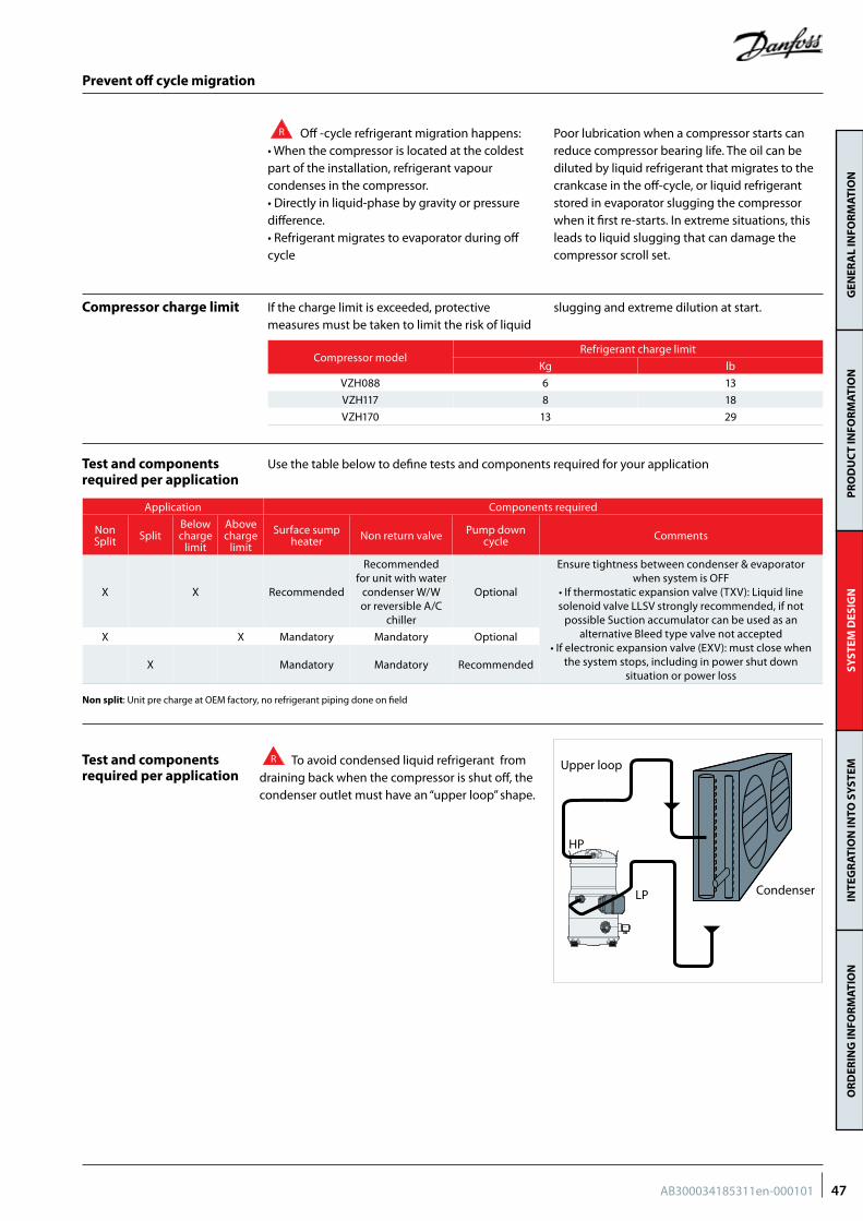
GEN
ERA
L IN
FOR
MAT
ION
PR
OD
UC
T IN
FOR
MAT
ION
SYST
EM D
ESIG
NIN
TEG
RAT
ION
INTO
SY
STEM
OR
DER
ING
INFO
RM
ATIO
N
Prevent off cycle migration
R Off -cycle refrigerant migration happens: • When the compressor is located at the coldest part of the installation, refrigerant vapour condenses in the compressor.• Directly in liquid-phase by gravity or pressure difference.• Refrigerant migrates to evaporator during off cycle
Poor lubrication when a compressor starts can reduce compressor bearing life. The oil can be diluted by liquid refrigerant that migrates to the crankcase in the off-cycle, or liquid refrigerant stored in evaporator slugging the compressor when it first re-starts. In extreme situations, this leads to liquid slugging that can damage the compressor scroll set.
R To avoid condensed liquid refrigerant from draining back when the compressor is shut off, the condenser outlet must have an “upper loop” shape.
If the charge limit is exceeded, protective measures must be taken to limit the risk of liquid
slugging and extreme dilution at start.
Use the table below to define tests and components required for your application
Compressor charge limit
Test and components required per application
Test and components required per application
Compressor modelRefrigerant charge limit
Kg lb
VZH088 6 13
VZH117 8 18
VZH170 13 29
Application Components required
Non Split Split
Below charge
limit
Above charge
limit
Surface sump heater Non return valve Pump down
cycle Comments
X X Recommended
Recommended for unit with water
condenser W/W or reversible A/C
chiller
Optional
Ensure tightness between condenser & evaporator when system is OFF
• If thermostatic expansion valve (TXV): Liquid line solenoid valve LLSV strongly recommended, if not
possible Suction accumulator can be used as an alternative Bleed type valve not accepted
• If electronic expansion valve (EXV): must close when the system stops, including in power shut down
situation or power loss
X X Mandatory Mandatory Optional
X Mandatory Mandatory Recommended
Non split: Unit pre charge at OEM factory, no refrigerant piping done on field
HP
LP Condenser
Upper loop
47AB300034185311en-000101
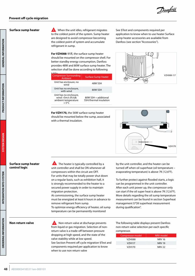
GEN
ERA
L IN
FOR
MAT
ION
PR
OD
UC
T IN
FOR
MAT
ION
SYST
EM D
ESIG
NIN
TEG
RAT
ION
INTO
SY
STEM
OR
DER
ING
INFO
RM
ATIO
N
R When the unit idles, refrigerant migrates to the coldest point of the system. Sump heater are designed to avoid compressor becoming the coldest point of system and accumulate refrigerant in sump.
See §Test and components required per application to know when to use heater Surface sump heater accessories are available from Danfoss (see section “Accessories”).
For VZH088-117, the surface sump heater should be mounted on the compressor shell. For better standby energy consumption, Danfoss provides 48W and 80W surface sump heater. The selection shall be done according to following table:
For VZH170, the 56W surface sump heater should be mounted below the sump, associated with a thermal insulation.
Surface sump heater
Surface sump heater control logic
Non return valve
Prevent off cycle migration
Compressor Surrounding Ambient Surface Sump Heater
Unit has enclosure, no wind 48W SSH
Unit has no enclosure, with wind 80W SSH
Unit has no enclosure, wind >5m/s (ft/s)&
ambient temperature <-5°C
80W SSH + additional SSH/thermal insulation
VZH088-117
VZH170
R The heater is typically controlled by a unit controller and shall be ON whenever all compressors within the circuit are OFF. For units that may be totally power shut down on a regular basis, such as exhibition hall, it is strongly recommended to the heater to a secured power supply in order to maintain migration protection. At commissioning, the surface sump heater must be energized at least 6 hours in advance to remove refrigerant from sump.To optimize energy efficiency of heater, oil sump temperature can be permanently monitored
by the unit controller, and the heater can be turned off when oil superheat (oil temperature – evaporating temperature) is above 7K (12.6°F).
To further protect against flooded starts, a logic can be programmed in the unit controller. After each unit power up, the compressor only can start if the oil super heat is above 7K (12.6°F).More details regarding the oil sump temperature measurement can be found in section Superheat management §“Oil superheat measurement during qualification”.
R Non-return valve at discharge prevents from liquid or gas migration. Selection of non-return valve is a trade-off between pressure dropping at high speed, and the state of the valve stability while at low speed.See Section Prevent off cycle migration §Test and components required per application to know when to use non return valve
The following table displays present Danfoss non-return valve selection per each specific compressor.
Compressor model NRV model
VZH088 NRV 16
VZH117 NRV 19
VZH170 NRV 22
48 AB300034185311en-000101
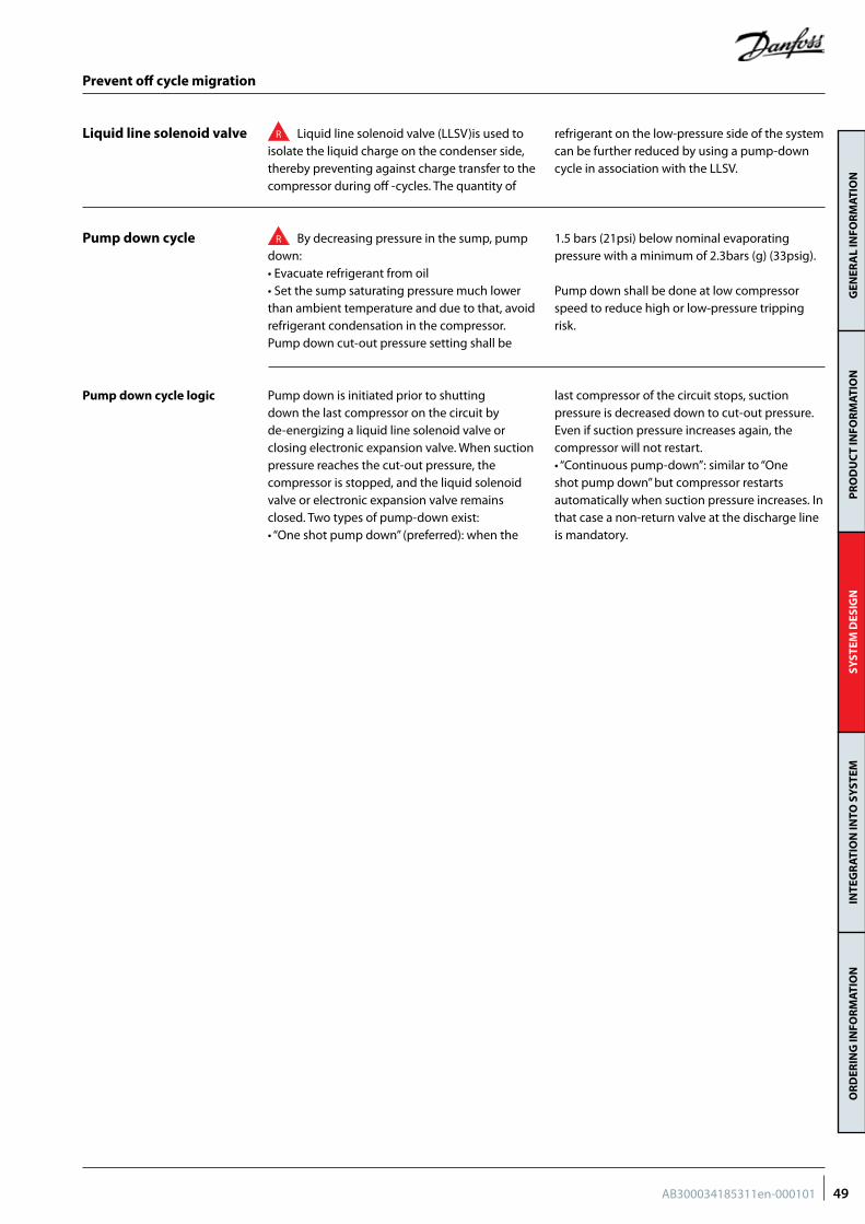
GEN
ERA
L IN
FOR
MAT
ION
PR
OD
UC
T IN
FOR
MAT
ION
SYST
EM D
ESIG
NIN
TEG
RAT
ION
INTO
SY
STEM
OR
DER
ING
INFO
RM
ATIO
N
R Liquid line solenoid valve (LLSV)is used to isolate the liquid charge on the condenser side, thereby preventing against charge transfer to the compressor during off -cycles. The quantity of
refrigerant on the low-pressure side of the system can be further reduced by using a pump-down cycle in association with the LLSV.
R By decreasing pressure in the sump, pump down:• Evacuate refrigerant from oil• Set the sump saturating pressure much lower than ambient temperature and due to that, avoid refrigerant condensation in the compressor.Pump down cut-out pressure setting shall be
1.5 bars (21psi) below nominal evaporating pressure with a minimum of 2.3bars (g) (33psig).
Pump down shall be done at low compressor speed to reduce high or low-pressure tripping risk.
Pump down is initiated prior to shutting down the last compressor on the circuit by de-energizing a liquid line solenoid valve or closing electronic expansion valve. When suction pressure reaches the cut-out pressure, the compressor is stopped, and the liquid solenoid valve or electronic expansion valve remains closed. Two types of pump-down exist:• “One shot pump down” (preferred): when the
last compressor of the circuit stops, suction pressure is decreased down to cut-out pressure. Even if suction pressure increases again, the compressor will not restart.• “Continuous pump-down”: similar to “One shot pump down” but compressor restarts automatically when suction pressure increases. In that case a non-return valve at the discharge line is mandatory.
Liquid line solenoid valve
Pump down cycle
Pump down cycle logic
Prevent off cycle migration
49AB300034185311en-000101
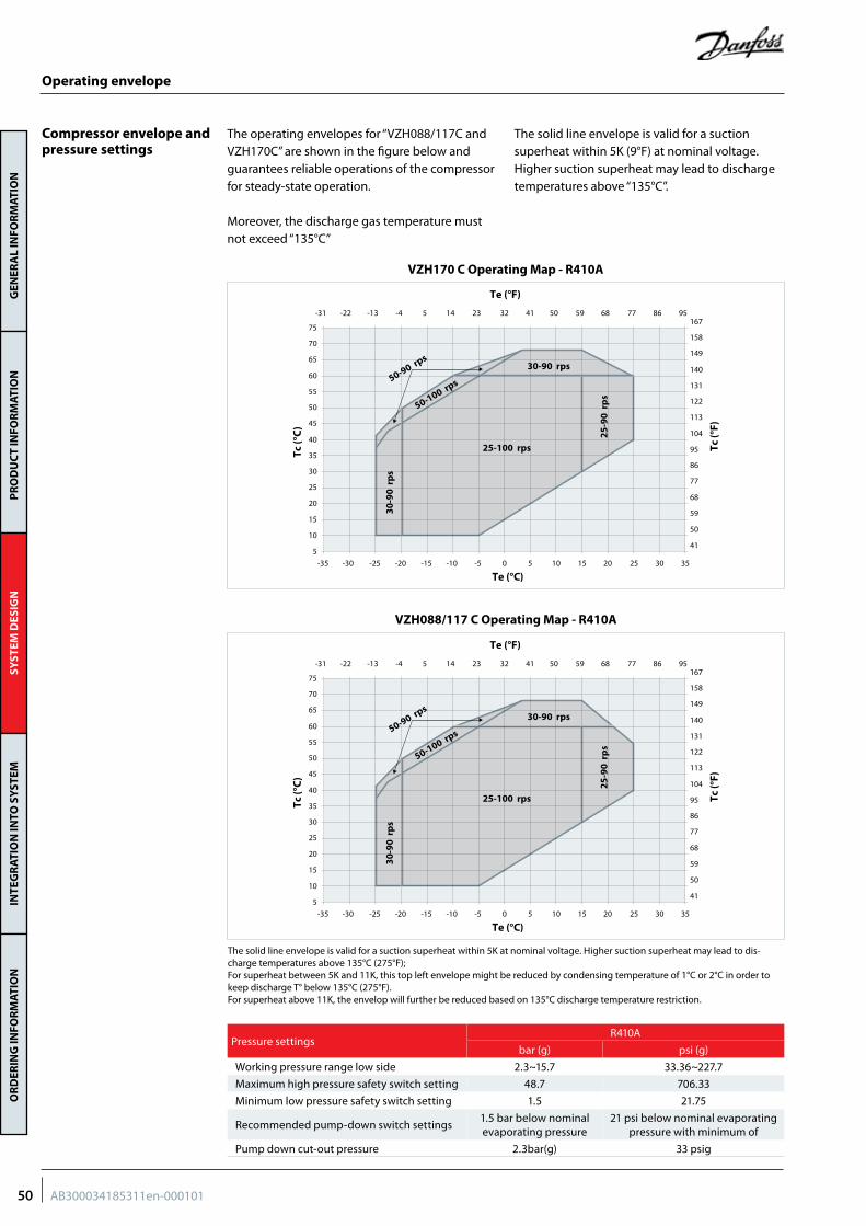
GEN
ERA
L IN
FOR
MAT
ION
PR
OD
UC
T IN
FOR
MAT
ION
SYST
EM D
ESIG
NIN
TEG
RAT
ION
INTO
SY
STEM
OR
DER
ING
INFO
RM
ATIO
N
The solid line envelope is valid for a suction superheat within 5K at nominal voltage. Higher suction superheat may lead to dis-charge temperatures above 135°C (275°F);For superheat between 5K and 11K, this top left envelope might be reduced by condensing temperature of 1°C or 2°C in order to keep discharge T° below 135°C (275°F).For superheat above 11K, the envelop will further be reduced based on 135°C discharge temperature restriction.
Pressure settingsR410A
bar (g) psi (g)
Working pressure range low side 2.3~15.7 33.36~227.7
Maximum high pressure safety switch setting 48.7 706.33
Minimum low pressure safety switch setting 1.5 21.75
Recommended pump-down switch settings1.5 bar below nominal evaporating pressure
21 psi below nominal evaporating pressure with minimum of
Pump down cut-out pressure 2.3bar(g) 33 psig
5
15
10
25
20
35
30
45
40
50
55
60
65
70
75
Tc (°
C)
30-9
0 r
ps
50-100 rps50-90 rps30-90 rps
25-100 rps
25-9
0 r
ps
Te (°C)-35 -30 -25 -20 -15 -10 -5 0 5 1510 30 352520
41
59
50
77
68
95
86
113
104
122
131
140
149
158
167
Tc (°
F)
Te (°F)
-31 -22 -13 -4 5 14 23 32 41 5950 86 957768
5
15
10
25
20
35
30
45
40
50
55
60
65
70
75
Tc (°
C)
30-9
0 r
ps
50-100 rps50-90 rps30-90 rps
25-100 rps
25-9
0 r
ps
Te (°C)-35 -30 -25 -20 -15 -10 -5 0 5 1510 30 352520
41
59
50
77
68
95
86
113
104
122
131
140
149
158
167
Tc (°
F)
Te (°F)
-31 -22 -13 -4 5 14 23 32 41 5950 86 957768
Compressor envelope and pressure settings
The operating envelopes for “VZH088/117C and VZH170C” are shown in the figure below and guarantees reliable operations of the compressor for steady-state operation.
Moreover, the discharge gas temperature must not exceed “135°C”
The solid line envelope is valid for a suction superheat within 5K (9°F) at nominal voltage. Higher suction superheat may lead to discharge temperatures above “135°C”.
Operating envelope
VZH088/117 C Operating Map - R410A
VZH170 C Operating Map - R410A
50 AB300034185311en-000101
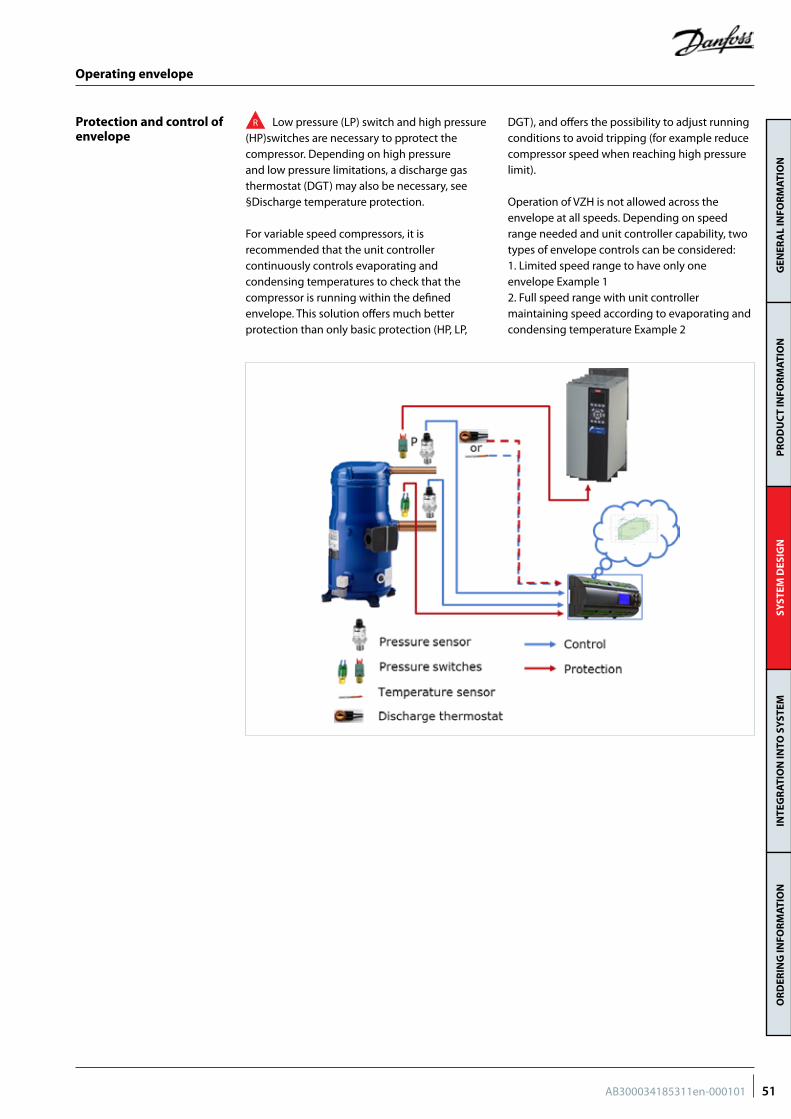
GEN
ERA
L IN
FOR
MAT
ION
PR
OD
UC
T IN
FOR
MAT
ION
SYST
EM D
ESIG
NIN
TEG
RAT
ION
INTO
SY
STEM
OR
DER
ING
INFO
RM
ATIO
N
Protection and control of envelope
R Low pressure (LP) switch and high pressure (HP)switches are necessary to pprotect the compressor. Depending on high pressure and low pressure limitations, a discharge gas thermostat (DGT) may also be necessary, see §Discharge temperature protection.
For variable speed compressors, it is recommended that the unit controller continuously controls evaporating and condensing temperatures to check that the compressor is running within the defined envelope. This solution offers much better protection than only basic protection (HP, LP,
DGT), and offers the possibility to adjust running conditions to avoid tripping (for example reduce compressor speed when reaching high pressure limit).
Operation of VZH is not allowed across the envelope at all speeds. Depending on speed range needed and unit controller capability, two types of envelope controls can be considered:1. Limited speed range to have only one envelope Example 12. Full speed range with unit controller maintaining speed according to evaporating and condensing temperature Example 2
Operating envelope
51AB300034185311en-000101
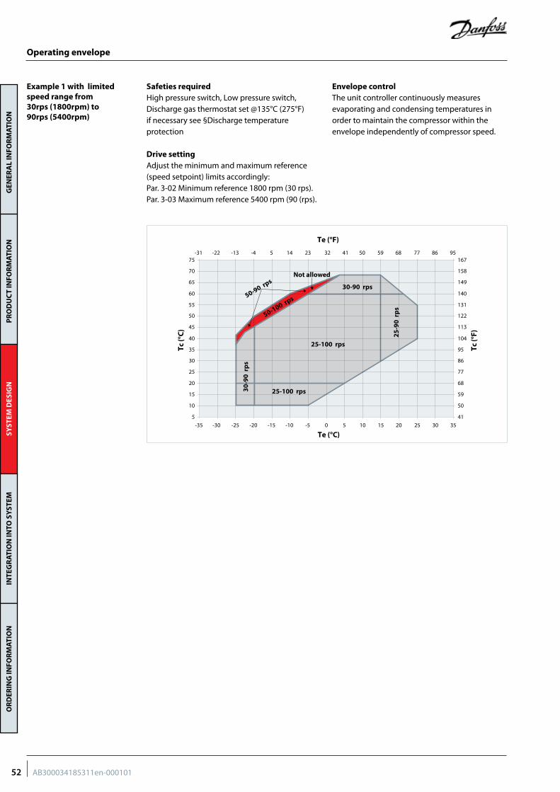
GEN
ERA
L IN
FOR
MAT
ION
PR
OD
UC
T IN
FOR
MAT
ION
SYST
EM D
ESIG
NIN
TEG
RAT
ION
INTO
SY
STEM
OR
DER
ING
INFO
RM
ATIO
N
Safeties required High pressure switch, Low pressure switch, Discharge gas thermostat set @135°C (275°F) if necessary see §Discharge temperature protection
Drive settingAdjust the minimum and maximum reference (speed setpoint) limits accordingly:Par. 3-02 Minimum reference 1800 rpm (30 rps).Par. 3-03 Maximum reference 5400 rpm (90 (rps).
Envelope controlThe unit controller continuously measures evaporating and condensing temperatures in order to maintain the compressor within the envelope independently of compressor speed.
Operating envelope
Example 1 with limited speed range from 30rps (1800rpm) to 90rps (5400rpm)
5
15
10
25
20
35
30
45
40
50
55
60
65
70
75
Tc (°
C)
50-100 rps50-90 rps30-90 rps
25-100 rps
25-100 rps25
-90
rp
s
Te (°C)-35 -30 -25 -20 -15 -10 -5 0 5 1510 30 352520
Not allowed
30-9
0 r
ps
41
59
50
77
68
95
86
113
104
122
131
140
149
158
167
Tc (°
F)
Te (°F)
-31 -22 -13 -4 5 14 23 32 41 5950 86 957768
52 AB300034185311en-000101
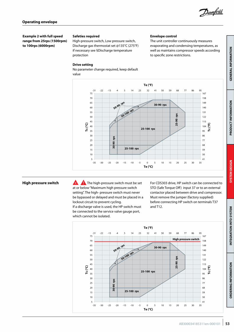
GEN
ERA
L IN
FOR
MAT
ION
PR
OD
UC
T IN
FOR
MAT
ION
SYST
EM D
ESIG
NIN
TEG
RAT
ION
INTO
SY
STEM
OR
DER
ING
INFO
RM
ATIO
N
Safeties required High-pressure switch, Low pressure switch, Discharge gas thermostat set @135°C (275°F) if necessary see §Discharge temperature protection
Drive settingNo parameter change required, keep default value
Envelope controlThe unit controller continuously measures evaporating and condensing temperatures, as well as maintains compressor speeds according to specific zone restrictions.
Example 2 with full speedrange from 25rps (1500rpm)to 100rps (6000rpm)
Operating envelope
High pressure switch R The high-pressure switch must be set at or below “Maximum high pressure switch setting”. The high- pressure switch must never be bypassed or delayed and must be placed in a lockout circuit to prevent cycling.If a discharge valve is used, the HP switch must be connected to the service valve gauge port, which cannot be isolated.
For CDS303 drive, HP switch can be connected to STO (Safe Torque Off) input 37 or to an external contactor placed between drive and compressor. Must remove the jumper (factory supplied) before connecting HP switch on terminals T37 and T12.
5
15
10
25
20
35
30
45
40
50
55
60
65
70
75
41
59
50
77
68
95
86
113
104
122
131
140
149
158
167
Tc (°
C)
Tc (°
F)
50-100 rps50-90 rps30-90 rps
25-100 rps
25-100 rps
25-9
0 r
ps
Te (°C)
Te (°F)
-35 -30 -25 -20 -15 -10 -5 0 5 1510 30 352520
-31 -22 -13 -4 5 14 23 32 41 5950 86 957768
30-9
0 r
ps
5
15
10
25
20
35
30
45
40
50
55
60
65
70
75
41
59
50
77
68
95
86
113
104
122
131
140
149
158
167
Tc (°
C)
Tc (°
F)
50-100 rps50-90 rps30-90 rps
25-100 rps
25-100 rps
25-9
0 r
ps
Te (°C)
Te (°F)
-35 -30 -25 -20 -15 -10 -5 0 5 1510 30 352520
-31 -22 -13 -4 5 14 23 32 41 5950 86 957768
30-9
0 r
ps
High pressure switch
53AB300034185311en-000101
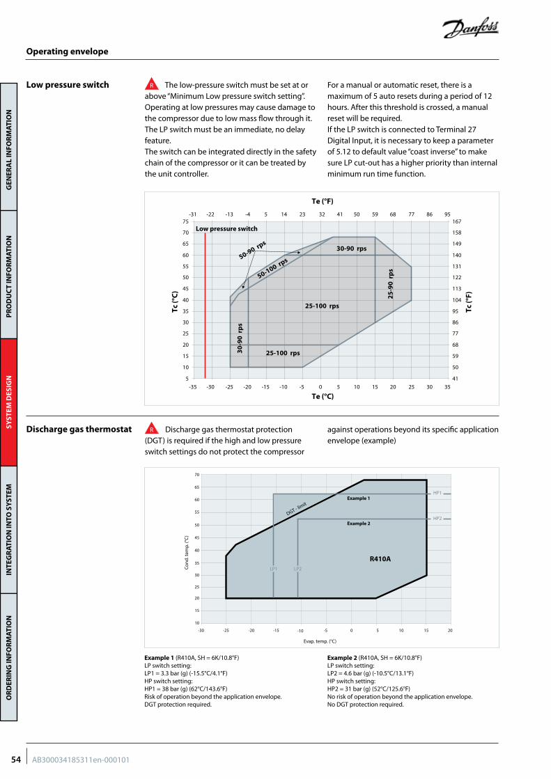
GEN
ERA
L IN
FOR
MAT
ION
PR
OD
UC
T IN
FOR
MAT
ION
SYST
EM D
ESIG
NIN
TEG
RAT
ION
INTO
SY
STEM
OR
DER
ING
INFO
RM
ATIO
N
Operating envelope
Low pressure switch
Discharge gas thermostat
R The low-pressure switch must be set at or above “Minimum Low pressure switch setting”.Operating at low pressures may cause damage to the compressor due to low mass flow through it.The LP switch must be an immediate, no delay feature.The switch can be integrated directly in the safety chain of the compressor or it can be treated by the unit controller.
For a manual or automatic reset, there is a maximum of 5 auto resets during a period of 12 hours. After this threshold is crossed, a manual reset will be required.If the LP switch is connected to Terminal 27 Digital Input, it is necessary to keep a parameter of 5.12 to default value “coast inverse” to make sure LP cut-out has a higher priority than internal minimum run time function.
R Discharge gas thermostat protection (DGT) is required if the high and low pressure switch settings do not protect the compressor
against operations beyond its specific application envelope (example)
70
65
60
55
50
45
40
35
30
25
20
15
10
-30 -25 -20 -15 -10 -5 0 5 10 15 20
Cond
. tem
p. (°
C)
Evap. temp. (°C)
LP1
HP2
HP1
R410A
DGT - limit
Example 1
Example 2
LP2
Example 1 (R410A, SH = 6K/10.8°F) LP switch setting: LP1 = 3.3 bar (g) (-15.5°C/4.1°F) HP switch setting: HP1 = 38 bar (g) (62°C/143.6°F) Risk of operation beyond the application envelope. DGT protection required.
Example 2 (R410A, SH = 6K/10.8°F) LP switch setting: LP2 = 4.6 bar (g) (-10.5°C/13.1°F) HP switch setting: HP2 = 31 bar (g) (52°C/125.6°F) No risk of operation beyond the application envelope. No DGT protection required.
5
15
10
25
20
35
30
45
40
50
55
60
65
70
75
41
59
50
77
68
95
86
113
104
122
131
140
149
158
167
Tc (°
C)
Tc (°
F)
50-100 rps50-90 rps30-90 rps
25-100 rps
25-100 rps
25-9
0 r
ps
Te (°C)
Te (°F)
-35 -30 -25 -20 -15 -10 -5 0 5 1510 30 352520
-31 -22 -13 -4 5 14 23 32 41 5950 86 957768
30-9
0 r
ps
Low pressure switch
54 AB300034185311en-000101
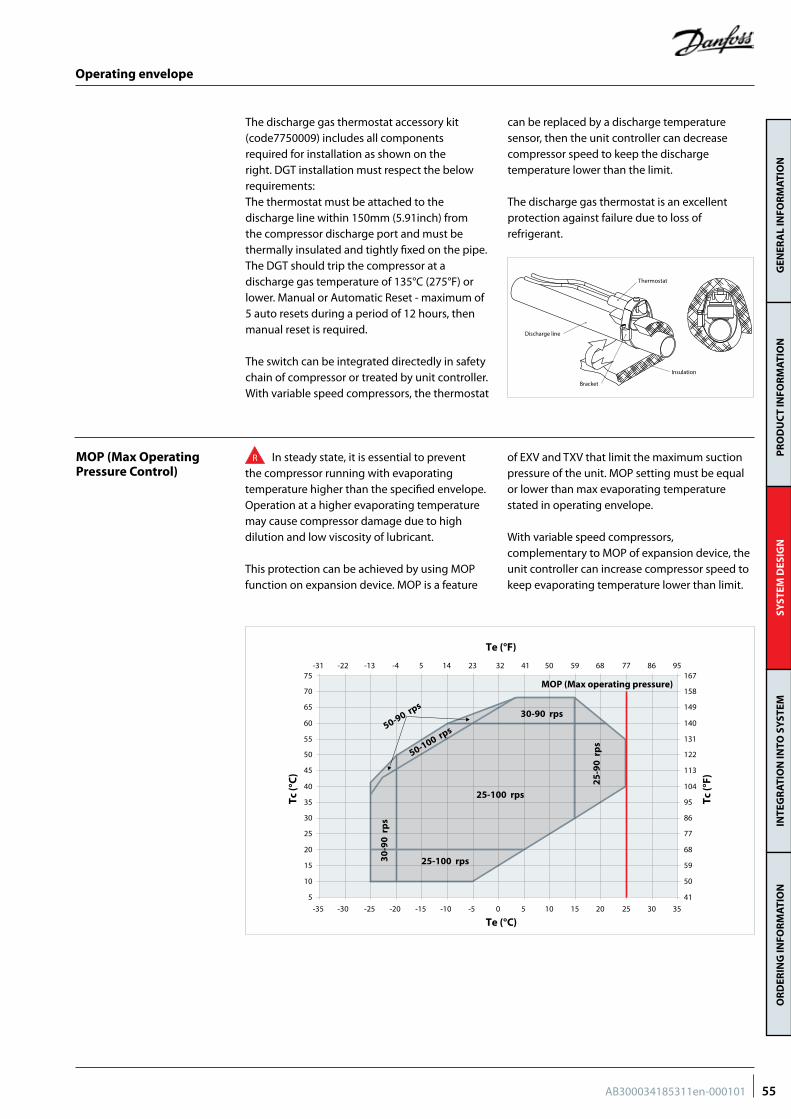
GEN
ERA
L IN
FOR
MAT
ION
PR
OD
UC
T IN
FOR
MAT
ION
SYST
EM D
ESIG
NIN
TEG
RAT
ION
INTO
SY
STEM
OR
DER
ING
INFO
RM
ATIO
N
MOP (Max Operating Pressure Control)
The discharge gas thermostat accessory kit (code7750009) includes all components required for installation as shown on the right. DGT installation must respect the below requirements:The thermostat must be attached to the discharge line within 150mm (5.91inch) from the compressor discharge port and must be thermally insulated and tightly fixed on the pipe.The DGT should trip the compressor at a discharge gas temperature of 135°C (275°F) or lower. Manual or Automatic Reset - maximum of 5 auto resets during a period of 12 hours, then manual reset is required.
The switch can be integrated directedly in safety chain of compressor or treated by unit controller.With variable speed compressors, the thermostat
can be replaced by a discharge temperature sensor, then the unit controller can decrease compressor speed to keep the discharge temperature lower than the limit.
The discharge gas thermostat is an excellent protection against failure due to loss of refrigerant.
Discharge line
Insulation
Bracket
Thermostat
Operating envelope
R In steady state, it is essential to prevent the compressor running with evaporating temperature higher than the specified envelope. Operation at a higher evaporating temperature may cause compressor damage due to high dilution and low viscosity of lubricant.
This protection can be achieved by using MOP function on expansion device. MOP is a feature
of EXV and TXV that limit the maximum suction pressure of the unit. MOP setting must be equal or lower than max evaporating temperature stated in operating envelope.
With variable speed compressors, complementary to MOP of expansion device, the unit controller can increase compressor speed to keep evaporating temperature lower than limit.
5
15
10
25
20
35
30
45
40
50
55
60
65
70
75
41
59
50
77
68
95
86
113
104
122
131
140
149
158
167
Tc (°
C)
Tc (°
F)
50-100 rps50-90 rps30-90 rps
25-100 rps
25-100 rps
25-9
0 r
ps
Te (°C)
Te (°F)
-35 -30 -25 -20 -15 -10 -5 0 5 1510 30 352520
-31 -22 -13 -4 5 14 23 32 41 5950 86 957768
30-9
0 r
ps
MOP (Max operating pressure)
55AB300034185311en-000101
GEN
ERA
L IN
FOR
MAT
ION
PR
OD
UC
T IN
FOR
MAT
ION
SYST
EM D
ESIG
NIN
TEG
RAT
ION
INTO
SY
STEM
OR
DER
ING
INFO
RM
ATIO
N
Sound level
Vibrations
Gas pulsation The Danfoss VZH scroll compressor has been designed and tested to ensure that gas pulsation is optimized for the most commonly encountered air conditioning pressure ratio. Manifolded compressors are equivalents to lagged sources of gas pulsation. Therefore, pulse level can vary during time.
If an unacceptable level is identified, a discharge muffler with the appropriate resonant volume and mass can be installed.
R Typical sounds and vibrations in systems can be broken down into the following three categories:• Sound radiation (through air)• Mechanical vibrations (through parts and structure)
• Gas pulsation (through refrigerant)
The following sections focus on the causes and methods of mitigation for each of the above sources.
R Compressor generates some vibrations that propagate into the surrounding parts and structure. The vibration level of a VZH compressor alone does not exceed 127 μm peak to peak. However, when system structure natural frequencies are close to running frequency, vibrations are amplified due to resonance phenomenon. A high vibration level is damageable for piping reliability and generates high sound levels.
To avoid resonance phenomenon, pipings and frame must have natural frequencies as far as possible from running frequencies. This could be challenging on a variable system as all resonant frequencies between min speed to maximum speed will be excited.
It is mandatory to check that piping vibrations are acceptable across speed range. This test can be done by increasing slowly speed
and monitoring piping behaviour through, strain gage, acceleration, or displacement measurement. As alternative visual check with strobe light can also emphasis high piping displacement.
If some resonant frequencies generate high piping vibration, problem can be solved by increasing piping stiffness with brackets or changing layout. Dampers can also be installed to mitigate vibration.
If some frequencies continue to produce unacceptable vibration levels, speed by-pass is adjustable in the frequency converter, in order to avoid some frequency ranges. Four by-pass ranges are adjustable, and settings can be made in parameter group 4.6x
Ensure that there is no direct contact between vibrating components and structure.
The sound radiating from the compressor is emitted through the air, the sound waves travel in all directions from the compressor.
We can consider two means to reduce compressors sound radiations:Acoustic hoods are quick and easy to install and do not increase the overall size of the compressors. Acoustic hoods are available from
Danfoss as accessories, in § “Product information” section “sound levels”
The use of sound insulation on the inside of the of the unit panels is an effective way to mitigate sound. You can find sound level and acoustic hood accessories in § “Product information” section “Sound levels”
Sound and vibrations management
56 AB300034185311en-000101
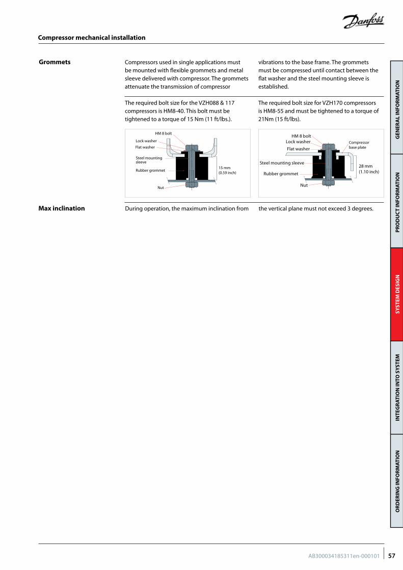
GEN
ERA
L IN
FOR
MAT
ION
PR
OD
UC
T IN
FOR
MAT
ION
SYST
EM D
ESIG
NIN
TEG
RAT
ION
INTO
SY
STEM
OR
DER
ING
INFO
RM
ATIO
N
Compressor mechanical installation
Grommets Compressors used in single applications must be mounted with flexible grommets and metal sleeve delivered with compressor. The grommets attenuate the transmission of compressor
vibrations to the base frame. The grommets must be compressed until contact between the flat washer and the steel mounting sleeve is established.
15 mm(0.59 inch)
HM 8 bolt
Lock washer
Flat washer
Steel mountingsleeve
Rubber grommet
Nut
The required bolt size for VZH170 compressors is HM8-55 and must be tightened to a torque of 21Nm (15 ft/lbs).
HM 8 boltLock washer
Flat washer
Steel mounting sleeve
Rubber grommet
Nut
28 mm(1.10 inch)
Compressorbase plate
The required bolt size for the VZH088 & 117 compressors is HM8-40. This bolt must be tightened to a torque of 15 Nm (11 ft/lbs.).
Max inclination During operation, the maximum inclination from the vertical plane must not exceed 3 degrees.
57AB300034185311en-000101
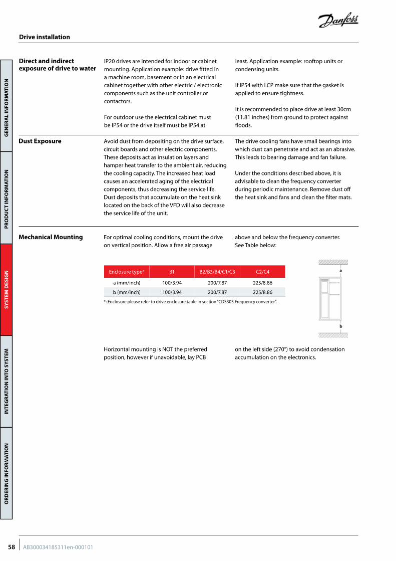
GEN
ERA
L IN
FOR
MAT
ION
PR
OD
UC
T IN
FOR
MAT
ION
SYST
EM D
ESIG
NIN
TEG
RAT
ION
INTO
SY
STEM
OR
DER
ING
INFO
RM
ATIO
N
Direct and indirect exposure of drive to water
Dust Exposure
Mechanical Mounting
Enclosure type* B1 B2/B3/B4/C1/C3 C2/C4
a (mm/inch) 100/3.94 200/7.87 225/8.86
b (mm/inch) 100/3.94 200/7.87 225/8.86
Drive installation
IP20 drives are intended for indoor or cabinet mounting. Application example: drive fitted in a machine room, basement or in an electrical cabinet together with other electric / electronic components such as the unit controller or contactors.
For outdoor use the electrical cabinet must be IP54 or the drive itself must be IP54 at
least. Application example: rooftop units or condensing units.
If IP54 with LCP make sure that the gasket is applied to ensure tightness.
It is recommended to place drive at least 30cm (11.81 inches) from ground to protect against floods.
Avoid dust from depositing on the drive surface, circuit boards and other electric components. These deposits act as insulation layers and hamper heat transfer to the ambient air, reducing the cooling capacity. The increased heat load causes an accelerated aging of the electrical components, thus decreasing the service life. Dust deposits that accumulate on the heat sink located on the back of the VFD will also decrease the service life of the unit.
The drive cooling fans have small bearings into which dust can penetrate and act as an abrasive. This leads to bearing damage and fan failure.
Under the conditions described above, it is advisable to clean the frequency converter during periodic maintenance. Remove dust off the heat sink and fans and clean the filter mats.
For optimal cooling conditions, mount the drive on vertical position. Allow a free air passage
above and below the frequency converter. See Table below:
*: Enclosure please refer to drive enclosure table in section “CDS303 Frequency converter”.
Horizontal mounting is NOT the preferred position, however if unavoidable, lay PCB
on the left side (270°) to avoid condensation accumulation on the electronics.
58 AB300034185311en-000101
GEN
ERA
L IN
FOR
MAT
ION
PR
OD
UC
T IN
FOR
MAT
ION
SYST
EM D
ESIG
NIN
TEG
RAT
ION
INTO
SY
STEM
OR
DER
ING
INFO
RM
ATIO
N
Drive installation
Drive ambient temperature
R The maximum ambient temperature for the drive is 50°C (122°F). (24-hour average maximum 45 °C). Do not exceed the maximum temperature limit.
The drive could operate lower to -10C (14F) with proper operation, such as inside the cabinet, install the space heater. However, LCP may not function well under such low temperature.
High Ambient Temperature
Test at the unit’s at highest ambient maximum load is recommended. Look for over temperature alarms.
Guidelines that support high ambient temperature: - Ensure clearance limits above and below the
drive for air circulation are respected. - The drive must be installed on a panel wall or
on a back plate to ensure proper cooling - Do not place the drive under direct sunlight. - Insulation inside the electrical panel can
reduce impact of sun radiation. - Additional air conditioning of the cabinet o
may be required.
The frequency converter has built-in temperature sensors and reacts immediately to critical values via hard-coded limits. In case of over-temperature inside the frequency converter, it automatically derates the switching frequency and the maximum allowed output current to reduce the internal heat. This can cause the compressor to trip due to insufficient current to drive the compressor.
Oversizing the drive for high temperature operations Should the application require full compressor envelope at high ambient temperature, then the CDS303 must be oversized to have better heat dissipation and deliver nominal current to the compressor.
For selection and further information, please contact Danfoss.
59AB300034185311en-000101
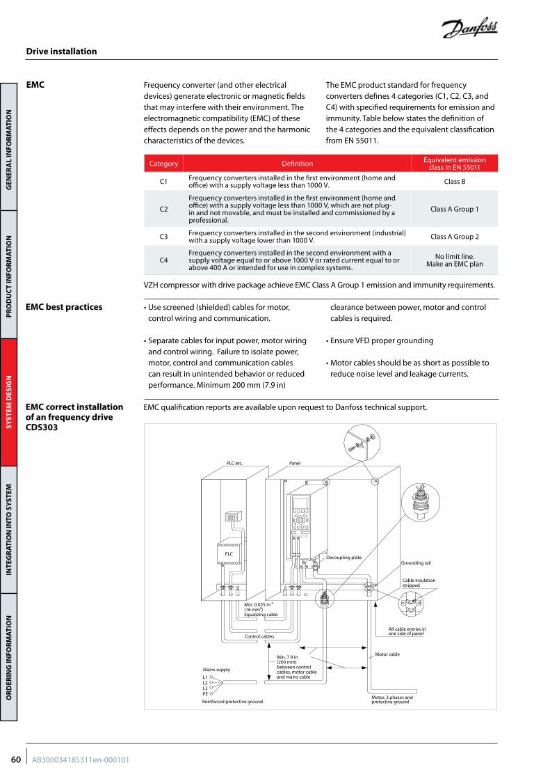
GEN
ERA
L IN
FOR
MAT
ION
PR
OD
UC
T IN
FOR
MAT
ION
SYST
EM D
ESIG
NIN
TEG
RAT
ION
INTO
SY
STEM
OR
DER
ING
INFO
RM
ATIO
N
Drive installation
EMC Frequency converter (and other electrical devices) generate electronic or magnetic fields that may interfere with their environment. The electromagnetic compatibility (EMC) of these effects depends on the power and the harmonic characteristics of the devices.
The EMC product standard for frequency converters defines 4 categories (C1, C2, C3, and C4) with specified requirements for emission and immunity. Table below states the definition of the 4 categories and the equivalent classification from EN 55011.
VZH compressor with drive package achieve EMC Class A Group 1 emission and immunity requirements.
Category Definition Equivalent emission class in EN 55011
C1 Frequency converters installed in the first environment (home and office) with a supply voltage less than 1000 V. Class B
C2
Frequency converters installed in the first environment (home and office) with a supply voltage less than 1000 V, which are not plug-in and not movable, and must be installed and commissioned by a professional.
Class A Group 1
C3 Frequency converters installed in the second environment (industrial) with a supply voltage lower than 1000 V. Class A Group 2
C4Frequency converters installed in the second environment with a supply voltage equal to or above 1000 V or rated current equal to or above 400 A or intended for use in complex systems.
No limit line. Make an EMC plan
EMC best practices • Use screened (shielded) cables for motor, control wiring and communication.
• Separate cables for input power, motor wiring and control wiring. Failure to isolate power, motor, control and communication cables can result in unintended behavior or reduced performance. Minimum 200 mm (7.9 in)
clearance between power, motor and control cables is required.
• Ensure VFD proper grounding
• Motor cables should be as short as possible to reduce noise level and leakage currents.
EMC correct installation of an frequency drive CDS303
PLC etc. Panel
Grounding railDecoupling plate
Cable insulationstripped
All cable entries inone side of panel
Motor cable
Motor, 3 phases andprotective groundReinforced protective ground
L1L2L3PE
Mains supply
Control cables
PLC
Min. 0.025 in ²(16 mm²)Equalizing cable
Min. 7.9 in(200 mm)between controlcables, motor cableand mains cable
EMC qualification reports are available upon request to Danfoss technical support.
60 AB300034185311en-000101
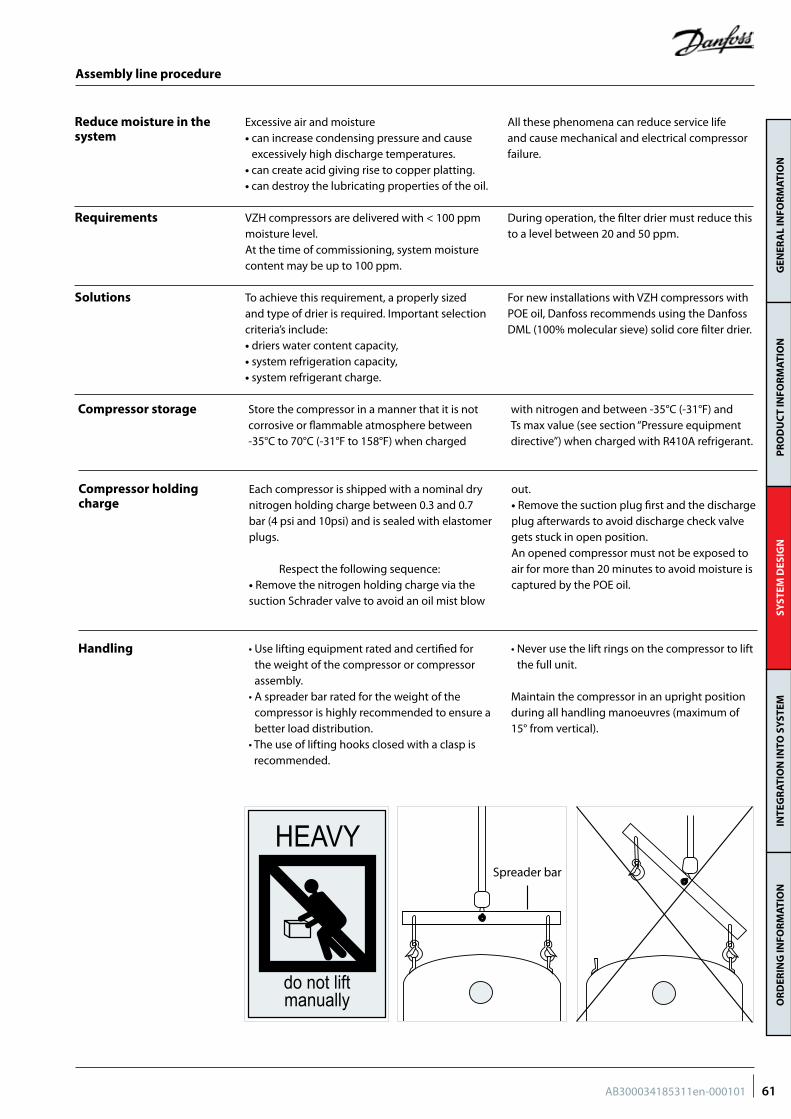
GEN
ERA
L IN
FOR
MAT
ION
PR
OD
UC
T IN
FOR
MAT
ION
SYST
EM D
ESIG
NIN
TEG
RAT
ION
INTO
SY
STEM
OR
DER
ING
INFO
RM
ATIO
N
Assembly line procedure
Excessive air and moisture • can increase condensing pressure and cause
excessively high discharge temperatures.• can create acid giving rise to copper platting.• can destroy the lubricating properties of the oil.
All these phenomena can reduce service life and cause mechanical and electrical compressor failure.
Requirements
Reduce moisture in the system
Solutions
VZH compressors are delivered with < 100 ppm moisture level. At the time of commissioning, system moisture content may be up to 100 ppm.
During operation, the filter drier must reduce this to a level between 20 and 50 ppm.
To achieve this requirement, a properly sized and type of drier is required. Important selection criteria’s include:• driers water content capacity,• system refrigeration capacity, • system refrigerant charge.
For new installations with VZH compressors with POE oil, Danfoss recommends using the Danfoss DML (100% molecular sieve) solid core filter drier.
Compressor holding charge
Handling
Compressor storage
Each compressor is shipped with a nominal dry nitrogen holding charge between 0.3 and 0.7 bar (4 psi and 10psi) and is sealed with elastomer plugs.
Respect the following sequence:• Remove the nitrogen holding charge via the suction Schrader valve to avoid an oil mist blow
out. • Remove the suction plug first and the discharge plug afterwards to avoid discharge check valve gets stuck in open position.An opened compressor must not be exposed to air for more than 20 minutes to avoid moisture is captured by the POE oil.
• Use lifting equipment rated and certified for the weight of the compressor or compressor assembly.
• A spreader bar rated for the weight of the compressor is highly recommended to ensure a better load distribution.
• The use of lifting hooks closed with a clasp is recommended.
• Never use the lift rings on the compressor to lift the full unit.
Maintain the compressor in an upright position during all handling manoeuvres (maximum of 15° from vertical).
Store the compressor in a manner that it is not corrosive or flammable atmosphere between -35°C to 70°C (-31°F to 158°F) when charged
with nitrogen and between -35°C (-31°F) and Ts max value (see section “Pressure equipment directive”) when charged with R410A refrigerant.
Spreader bar
HEAVY
do not liftmanually
61AB300034185311en-000101
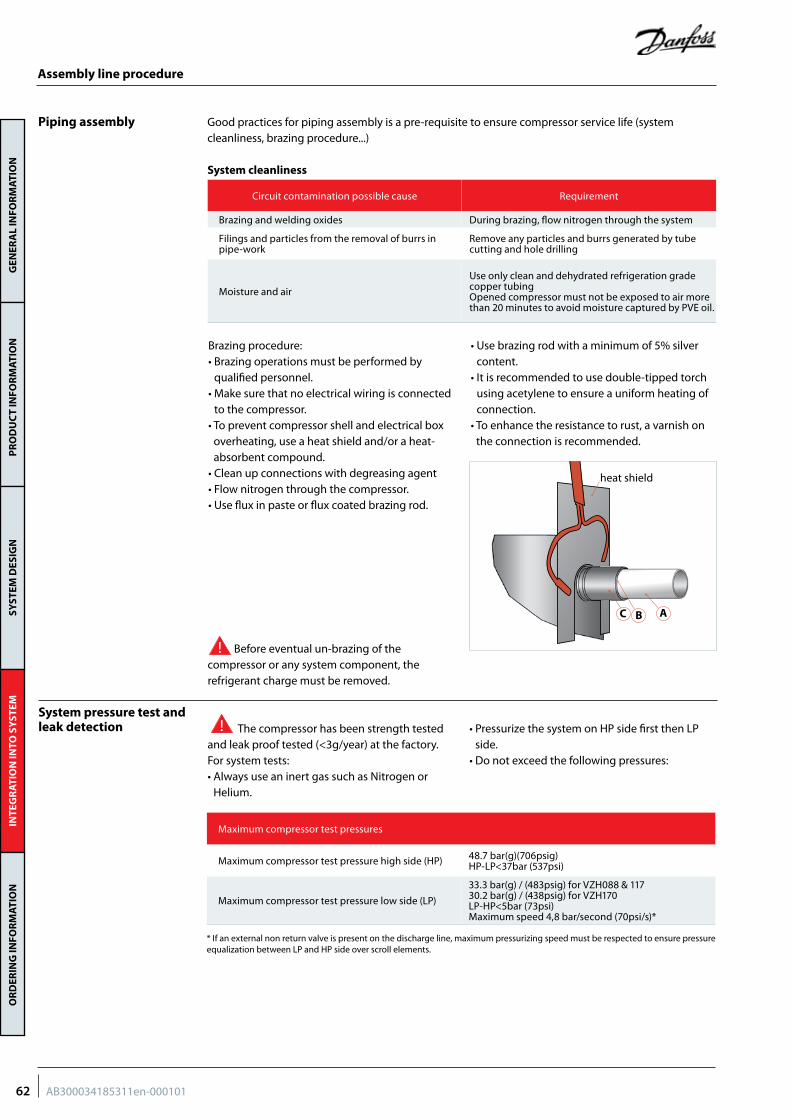
GEN
ERA
L IN
FOR
MAT
ION
PR
OD
UC
T IN
FOR
MAT
ION
SYST
EM D
ESIG
NIN
TEG
RAT
ION
INTO
SY
STEM
OR
DER
ING
INFO
RM
ATIO
N
Assembly line procedure
Piping assembly Good practices for piping assembly is a pre-requisite to ensure compressor service life (system cleanliness, brazing procedure...)
System cleanliness
Circuit contamination possible cause Requirement
Brazing and welding oxides During brazing, flow nitrogen through the system
Filings and particles from the removal of burrs in pipe-work
Remove any particles and burrs generated by tube cutting and hole drilling
Moisture and air
Use only clean and dehydrated refrigeration grade copper tubingOpened compressor must not be exposed to air more than 20 minutes to avoid moisture captured by PVE oil.
Brazing procedure:• Brazing operations must be performed by
qualified personnel.• Make sure that no electrical wiring is connected
to the compressor.• To prevent compressor shell and electrical box
overheating, use a heat shield and/or a heat-absorbent compound.
• Clean up connections with degreasing agent• Flow nitrogen through the compressor.• Use flux in paste or flux coated brazing rod.
• Use brazing rod with a minimum of 5% silver content.
• It is recommended to use double-tipped torch using acetylene to ensure a uniform heating of connection.
• To enhance the resistance to rust, a varnish on the connection is recommended.
Before eventual un-brazing of the compressor or any system component, the refrigerant charge must be removed.
System pressure test and leak detection The compressor has been strength tested
and leak proof tested (<3g/year) at the factory. For system tests:• Always use an inert gas such as Nitrogen or
Helium.
• Pressurize the system on HP side first then LP side.
• Do not exceed the following pressures:
Maximum compressor test pressures
Maximum compressor test pressure high side (HP) 48.7 bar(g)(706psig)HP-LP<37bar (537psi)
Maximum compressor test pressure low side (LP)
33.3 bar(g) / (483psig) for VZH088 & 11730.2 bar(g) / (438psig) for VZH170LP-HP<5bar (73psi)Maximum speed 4,8 bar/second (70psi/s)*
* If an external non return valve is present on the discharge line, maximum pressurizing speed must be respected to ensure pressure equalization between LP and HP side over scroll elements.
heat shield
C B A
62 AB300034185311en-000101
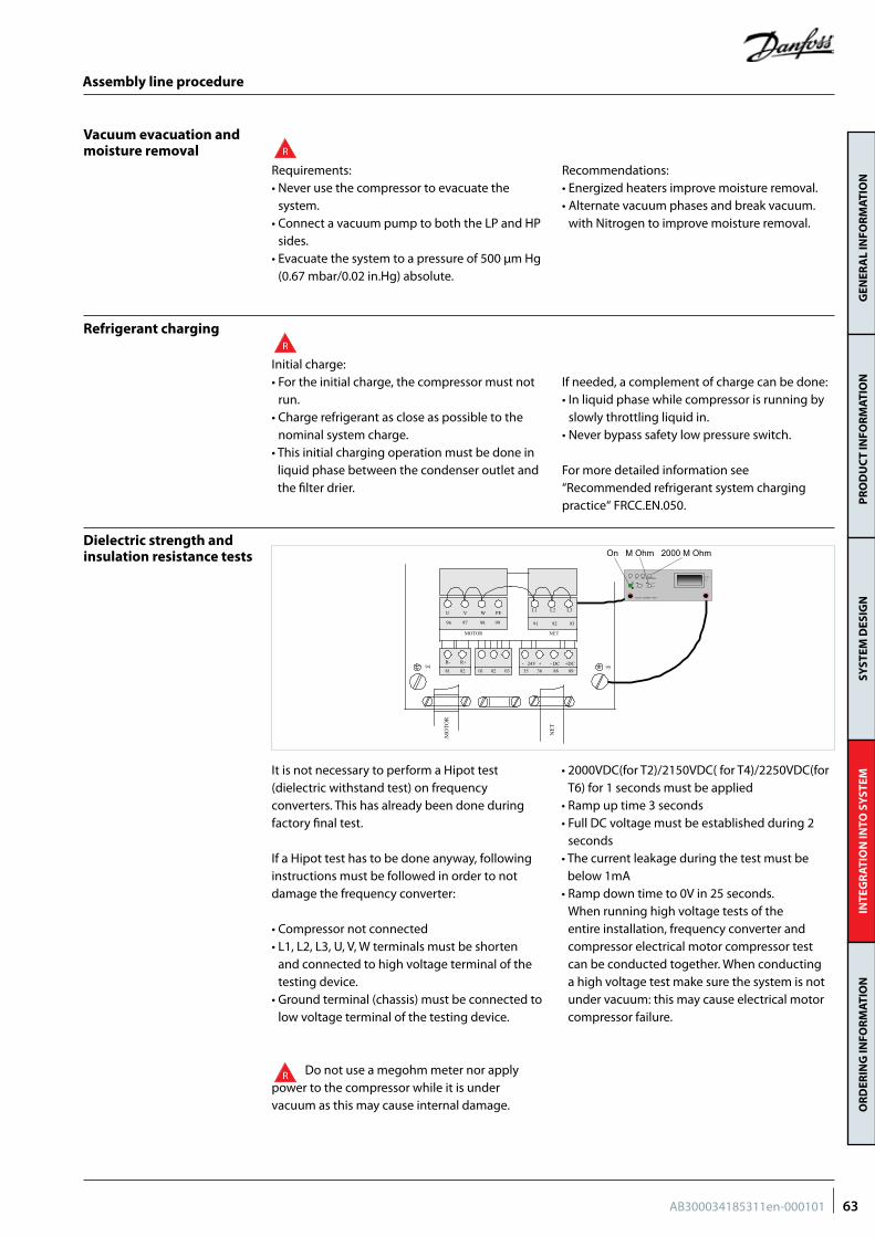
GEN
ERA
L IN
FOR
MAT
ION
PR
OD
UC
T IN
FOR
MAT
ION
SYST
EM D
ESIG
NIN
TEG
RAT
ION
INTO
SY
STEM
OR
DER
ING
INFO
RM
ATIO
N
Assembly line procedure
Vacuum evacuation and moisture removal
Refrigerant charging
Dielectric strength and insulation resistance tests
Requirements: • Never use the compressor to evacuate the
system. • Connect a vacuum pump to both the LP and HP
sides. • Evacuate the system to a pressure of 500 μm Hg
(0.67 mbar/0.02 in.Hg) absolute.
Recommendations:• Energized heaters improve moisture removal.• Alternate vacuum phases and break vacuum.
with Nitrogen to improve moisture removal.
Initial charge:• For the initial charge, the compressor must not
run.• Charge refrigerant as close as possible to the
nominal system charge.• This initial charging operation must be done in
liquid phase between the condenser outlet and the filter drier.
If needed, a complement of charge can be done:• In liquid phase while compressor is running by
slowly throttling liquid in. • Never bypass safety low pressure switch.
For more detailed information see “Recommended refrigerant system charging practice“ FRCC.EN.050.
Do not use a megohm meter nor apply power to the compressor while it is under vacuum as this may cause internal damage.
R
R
R
It is not necessary to perform a Hipot test (dielectric withstand test) on frequency converters. This has already been done during factory final test.
If a Hipot test has to be done anyway, following instructions must be followed in order to not damage the frequency converter:
• Compressor not connected• L1, L2, L3, U, V, W terminals must be shorten
and connected to high voltage terminal of the testing device.
• Ground terminal (chassis) must be connected to low voltage terminal of the testing device.
• 2000VDC(for T2)/2150VDC( for T4)/2250VDC(for T6) for 1 seconds must be applied
• Ramp up time 3 seconds• Full DC voltage must be established during 2
seconds• The current leakage during the test must be
below 1mA• Ramp down time to 0V in 25 seconds.
When running high voltage tests of the entire installation, frequency converter and compressor electrical motor compressor test can be conducted together. When conducting a high voltage test make sure the system is not under vacuum: this may cause electrical motor compressor failure.
L1 L2 L3
91 92 93
U V W PE
96 97 98 99
NETMOTOR
R- R+
81 82 01 02 03- 24V + - DC +DC 35 36 88 89
MO
TOR
NET
9594
2 20 200 2000MOhm
+
-
20 ohm
M ohm
Gossen - ISOWID - 0413
M ohmVOhm
On M Ohm 2000 M Ohm
63AB300034185311en-000101
GEN
ERA
L IN
FOR
MAT
ION
PR
OD
UC
T IN
FOR
MAT
ION
SYST
EM D
ESIG
NIN
TEG
RAT
ION
INTO
SY
STEM
OR
DER
ING
INFO
RM
ATIO
N
Commissioning
Preliminary checkCheck electrical power supply:
• Phase order: Reverse rotation is obvious if the compressor does not build up pressure and sound level is abnormal high. VZH compressor will only operate properly in one direction. If electrical connections are done correctly between the drive and the compressor
terminals (compressor terminals T1,T2,T3 and drive terminals U, V & W matching), the drive will provide correct phase supply to the compressor, and reverse rotation will be not possible:For more details refer to “Motor protection”.
• Voltage and voltage unbalance within tolerance: For more details refer to section “Motor voltage”.
Initial start-up
System monitoring
• Cranckcase heaters must be energized at least 6 hours in advance to remove refrigerant.
• Do not provide any power to the drive unless suction and discharge service valves on compressor are open, if installed.
• Energize the drive. The compressor must start, according to defined ramp-up settings. If the compressor does not start, check wiring conformity.
• Check the frequency converter control panel: If any alarm is displayed check the wiring and in
particular the polarity of the control cables.If an alarm is shown, refer to the frequency converter application manual. Verify in particular the combination of compressor, frequency converter and refrigerant.
• Check current draw and voltage levels on the mains. The values for the compressor electrical motor can be directly displayed on the frequency converter control panel.
The system must be monitored after initial startup for a minimum of 60 minutes to ensure proper operating characteristics such as:• Proper metering device operation and desired
superheat readings• Suction and discharge pressure are within
acceptable levels• Surface sump heaters must be energized at least
6 hours in advance to remove refrigerant.
• Correct oil level in compressor sump indicates proper oil return
• Low foaming in sight glass and compressor sump temperature above 7K saturation temperature to show that there is no refrigerant migration taking place
• Current draw of compressor within acceptable values (RLA ratings)
• No abnormal vibrations and noise.
In installations with good oil return and line runs up to 15m (49.2 feet), no additional oil is required. If installation lines exceed 15m (49.2 feet), additional oil may be needed. 3% of the total system refrigerant charge (in kg/lb) can be used to roughly define the required oil top-up quantity (in liters) but in any case the oil charge has to be adjusted based on the oil level in the compressor sight glass.
When the compressor is running under stabilized conditions, the oil level must be visible in the sight glass.
The presence of foam filling in the sight glass indicates large concentration of refrigerant in the oil and / or presence of liquid returning to the compressor.
The oil level can also be checked a few minutes after the compressor stops, the level must be visible in sight glass.
When the compressor is off, the level in the sight glass can be influenced by the presence of refrigerant in the oil.
Top-up the oil while the compressor is idle. Use the schrader connector or any other accessible connector on the compressor suction line and a suitable pump.
Oil level checking and top-up
64 AB300034185311en-000101
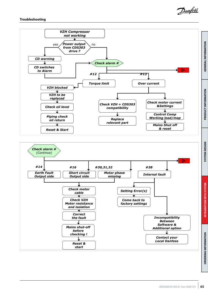
GEN
ERA
L IN
FOR
MAT
ION
PR
OD
UC
T IN
FOR
MAT
ION
SYST
EM D
ESIG
NIN
TEG
RAT
ION
INTO
SY
STEM
OR
DER
ING
INFO
RM
ATIO
N
Troubleshooting
Commercial Compressors March, 2014| 1
VZH Compressornot working
Power output from CDS303
drive ?
CD warning
CD switches to Alarm
Check alarm #
Torque limitVZH blocked
Check oil level
VZH to bereplaced
Piping checkoil return
Reset & Start
Over current
Check VZH + CDS303compatibility
Replacerelevant part
Check motor current &Settings
Control CompWorking load/map
Mains Shut off& reset
yes no
#12 #13
Commercial Compressors March, 2014| 2
#14
Earth FaultOutput side
Check motorcable
Correct the fault
Check VZHMotor resistance
and isolation
Reset &start
Check alarm #(Continue)
#16
Short circuitOutput side
#30,31,32
Motor phasemissing
#38
Internal fault
Setting Error(s)
IncompatibilityBetween
Software &Additional option
Come back to factory settings
Contact yourLocal Danfoss
Mains shut-off before
checking !
65AB300034185311en-000101
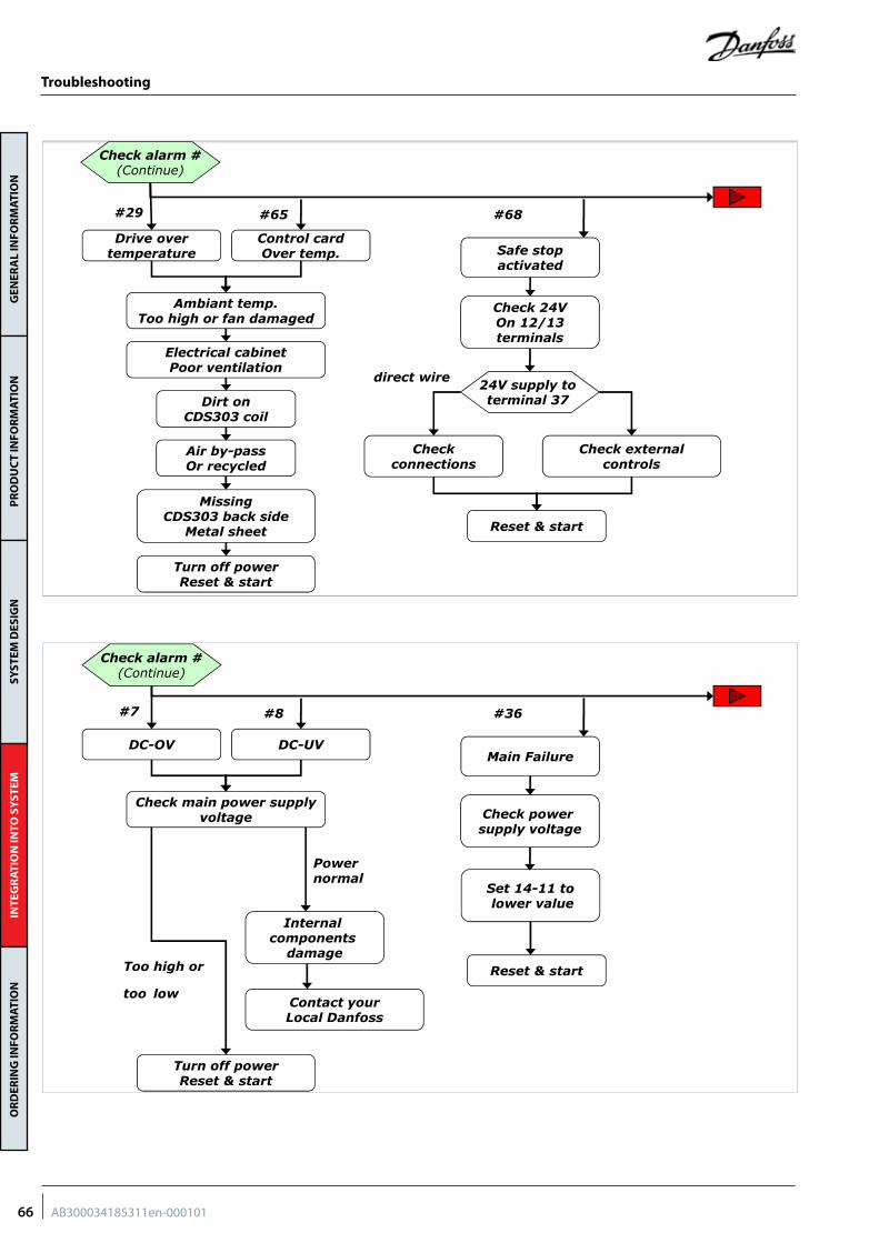
GEN
ERA
L IN
FOR
MAT
ION
PR
OD
UC
T IN
FOR
MAT
ION
SYST
EM D
ESIG
NIN
TEG
RAT
ION
INTO
SY
STEM
OR
DER
ING
INFO
RM
ATIO
N
Troubleshooting
Commercial Compressors March, 2014| 3
Drive overtemperature
Ambiant temp.Too high or fan damaged
Dirt on CDS303 coil
Electrical cabinetPoor ventilation
Air by-passOr recycled
Missing CDS303 back side
Metal sheet
Control cardOver temp. Safe stop
activated
Check 24VOn 12/13terminals
24V supply to terminal 37
Turn off powerReset & start
Check externalcontrols
Checkconnections
Reset & start
#29
Check alarm #(Continue)
#65 #68
direct wire
Commercial Compressors March, 2014| 4
DC-OV
Check main power supply voltage
DC-UVMain Failure
Check power supply voltage
Turn off powerReset & start
Reset & start
#7
Check alarm #(Continue)
#8 #36
Too high or
too low
Power normal
Set 14-11 tolower value
Internal components
damage
Contact yourLocal Danfoss
66 AB300034185311en-000101
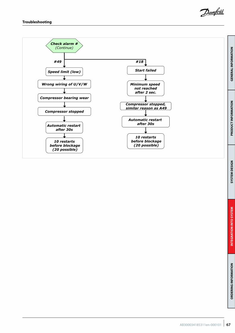
GEN
ERA
L IN
FOR
MAT
ION
PR
OD
UC
T IN
FOR
MAT
ION
SYST
EM D
ESIG
NIN
TEG
RAT
ION
INTO
SY
STEM
OR
DER
ING
INFO
RM
ATIO
N
Troubleshooting
Commercial Compressors March, 2014| 5
Speed limit (low)
Automatic restart after 30s
Wrong wiring of U/V/W
Start failed
Minimum speed not reachedafter 2 sec.
Compressor stopped,similar reason as A49
Automatic restart after 30s
10 restartsbefore blockage
(20 possible)
#49
Check alarm #(Continue)
#18
Compressor stopped
Compressor bearing wear
10 restartsbefore blockage
(20 possible)
67AB300034185311en-000101
GEN
ERA
L IN
FOR
MAT
ION
PR
OD
UC
T IN
FOR
MAT
ION
SYST
EM D
ESIG
NIN
TEG
RAT
ION
INTO
SY
STEM
OR
DER
ING
INFO
RM
ATIO
N
Dismantal and disposal
Danfoss recommends that compressors and compressor oil should be recycled by a suitable company at its site.
68 AB300034185311en-000101
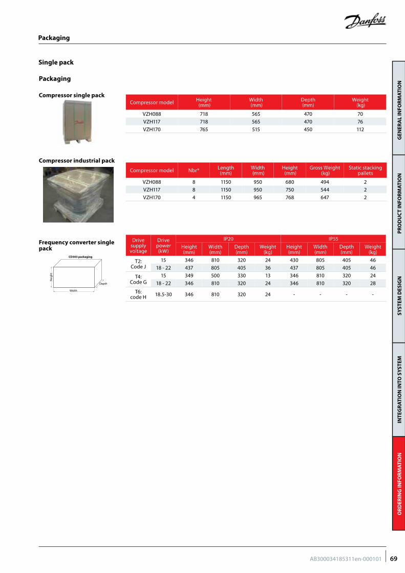
GEN
ERA
L IN
FOR
MAT
ION
PR
OD
UC
T IN
FOR
MAT
ION
SYST
EM D
ESIG
NIN
TEG
RAT
ION
INTO
SY
STEM
OR
DER
ING
INFO
RM
ATIO
N
Packaging
Single pack
Compressor single pack
Compressor industrial pack
Packaging
Compressor model Height (mm)
Width (mm)
Depth (mm)
Weight (kg)
VZH088 718 565 470 70
VZH117 718 565 470 76
VZH170 765 515 450 112
Compressor model Nbr* Length(mm)
Width (mm)
Height (mm)
Gross Weight (kg)
Static stacking pallets
VZH088 8 1150 950 680 494 2
VZH117 8 1150 950 750 544 2
VZH170 4 1150 965 768 647 2
Frequency converter single pack
Drive supply voltage
Drive power (kW)
IP20 IP55
Height (mm)
Width(mm)
Depth (mm)
Weight (kg)
Height (mm)
Width (mm)
Depth (mm)
Weight (kg)
T2: Code J
15 346 810 320 24 430 805 405 46
18 - 22 437 805 405 36 437 805 405 46
T4: Code G
15 349 500 330 13 346 810 320 24
18 - 22 346 810 320 24 346 810 320 28
T6: code H 18.5-30 346 810 320 24 - - - -
Depth
Heigh
t
Width
CD303 packaging
69AB300034185311en-000101
GEN
ERA
L IN
FOR
MAT
ION
PR
OD
UC
T IN
FOR
MAT
ION
SYST
EM D
ESIG
NIN
TEG
RAT
ION
INTO
SY
STEM
OR
DER
ING
INFO
RM
ATIO
N
Ordering codes
Single pack
Industrial pack
Danfoss scroll compressors VZH can be ordered in either industrial packs or in single packs. Drive
can be ordered in single packs. Please use the code numbers from below tables for ordering.
Compressor code numbers
Compressor model Equipment version Technical Name
X=motor code
G380-480V/3ph/
50&60Hz
J200-240V/3ph/
50&60Hz
H525-600V/3ph/
50&60Hz
VZH088Single VZH088CXANA 120G0189 120G0190 120G0191
Unified VZH088CXDNA 120G0192 120G0193 120G0194
VZH117Single VZH117CXANA 120G0195 120G0196 120G0197
Unified VZH117CXDNA 120G0198 120G0199 120G0200
VZH170Single VZH170CXANA 120G0201 120G0203 120G0204
Unified VZH170CXDNA 120G0205 120G0206 120G0207
Compressor model Equipment version Technical Name
X = Motor code
G380-480V/3ph/
50&60Hz
J200-240V/3ph/
50&60Hz
VZH088Single VZH088CXANA 120G0222 120G0223
Unified VZH088CXDNA 120G0224 120G0225
VZH117Single VZH117CXANA 120G0226 120G0227
Unified VZH117CXDNA 120G0228 120G0229
VZH170Single VZH170CXANA 120G0230 120G0231
Unified VZH170CXDNA 120G0232 120G0233
Coils Coil model Code no.
208V-240V coil + adaptor 120Z0521
24V coil + adaptor 120Z0522
70 AB300034185311en-000101
GEN
ERA
L IN
FOR
MAT
ION
PR
OD
UC
T IN
FOR
MAT
ION
SYST
EM D
ESIG
NIN
TEG
RAT
ION
INTO
SY
STEM
OR
DER
ING
INFO
RM
ATIO
N
VZH voltage code G - 380-480 Volt
VZH voltage code H - 525-600 Volt
Compressormodel
Frequency converter
Model & power IP class RFI class Coating Code n° for ordering
VZH088-G CDS30315.0kW
IP20
H3No 134G3576
Yes 134G3577
H2No 134F9366
Yes 134G3578
IP55
H3No 134G4008
Yes 134G4010
H2No 134G4012
Yes 134G4013
VZH117-G CDS30318.5kW
IP20
H3No 134G3579
Yes 134G3580
H2No 134F9368
Yes 134G3581
IP55
H3No 134G4015
Yes 134G4016
H2No 134G4018
Yes 134G4019
VZH170-G CDS30322.0kW
IP20
H3No 134G3582
Yes 134G3583
H2No 134F9371
Yes 134G3584
IP55
H3No 134G4020
Yes 134G4021
H2No 134G4022
Yes 134G4023
Compressormodel
Frequency converter
Model & power IP class RFI class Code n° for ordering
VZH088-H CDS30318.5kW IP20 HX 134L7237
VZH117-H CDS30330kW IP20 HX 134L7239
VZH170-H CDS30330kW IP20 HX 134L7239
LCP: user interface 120Z0326 (accessory)
71AB300034185311en-000101
GEN
ERA
L IN
FOR
MAT
ION
PR
OD
UC
T IN
FOR
MAT
ION
SYST
EM D
ESIG
NIN
TEG
RAT
ION
INTO
SY
STEM
OR
DER
ING
INFO
RM
ATIO
N
Compressormodel
Frequency converter
Model & power IP class RFI class Coating Code n° for ordering
VZH088-J CDS30315.0kW
IP20
H3 No 134G3474
H2No 134F9361
Yes 134X1964
IP55
H3 No 134G4001
H2 No 134G4002
VZH117-J CDS30318.5kW
IP20
H3 No 134G3585
H2No 134F9363
Yes 134X1965
IP55
H3 No 134G4003
H2 No 134G4004
VZH170-J CDS30322.0kW
IP20
H3 No 134G3586
H2No 134F9365
Yes 134X1966
IP55
H3 No 134G4005
H2 No 134G4006
VZH voltage code J - 200-240 Volt
LCP: user interface 120Z0326 (accessory)
72 AB300034185311en-000101
GEN
ERA
L IN
FOR
MAT
ION
PR
OD
UC
T IN
FOR
MAT
ION
SYST
EM D
ESIG
NIN
TEG
RAT
ION
INTO
SY
STEM
OR
DER
ING
INFO
RM
ATIO
N
Compressormodel
Frequency converter
Model & power IP class RFI class Coating Code n° for ordering
VZH088-J CDS30315.0kW
IP20
H3 No 134G3474
H2No 134F9361
Yes 134X1964
IP55
H3 No 134G4001
H2 No 134G4002
VZH117-J CDS30318.5kW
IP20
H3 No 134G3585
H2No 134F9363
Yes 134X1965
IP55
H3 No 134G4003
H2 No 134G4004
VZH170-J CDS30322.0kW
IP20
H3 No 134G3586
H2No 134F9365
Yes 134X1966
IP55
H3 No 134G4005
H2 No 134G4006
Accessories
Valves, adapters, connectors & gaskets for use on suction and discharge connections
Surface sump heaters
Type Code n° Description Application Packaging Pack size
120Z0388 Surface sump heater, 80 W, 24 V, CE, UL
VZH088-117
Multipack 8
120Z0389 Surface sump heater, 80 W, 230 V, CE, UL Multipack 8
120Z0390 Surface sump heater, 80 W, 400 V, CE, UL Multipack 8
120Z0391 Surface sump heater, 80 W, 460 V,CE, UL Multipack 8
120Z0402 Surface sump heater, 80 W, 575 V, CE, UL Multipack 8
120Z0360 Surface sump heater + bottom insulation, 56 W, 24 V, CE, UL
VZH170
Multipack 6
120Z0376 Surface sump heater + bottom insulation, 56 W, 230 V, CE, UL Multipack 6
120Z0377 Surface sump heater + bottom insulation, 56 W, 400 V, CE, UL Multipack 6
120Z0378 Surface sump heater + bottom insulation, 56 W, 460 V, CE, UL Multipack 6
120Z0379 Surface sump heater + bottom insulation, 56 W, 575 V, CE, UL Multipack 6
Type Code n° Description Application Packaging Pack size
120Z0157 Discharge temperature sensor / converter kit VZH all m odels Single pack 1
120Z0158 Discharge temperature sensor VZH all models Single pack 1
120Z0159 Discharge temperature converter VZH all models Single pack 1
7750009 Discharge thermostat kit VZH all models Multipack 10
Discharge thermostats and sensors
Lubricant, acoustic hoods and spare parts
Type Code n° Description Application Packaging Pack size
120Z0509 VZH088-G acoustic hood VZH088-G/H Single pack 1
120Z0510 VZH088-J acoustic hood VZH088-J Single pack 1
120Z0511 VZH088-G manifolding acoustic hood VZH088-G/H manifolding Single pack 1
120Z0512 VZH088-J manifolding acoustic hood VZH088-J manifolding Single pack 1
120Z0513 VZH117-G acoustic hood VZH117-G/H Single pack 1
120Z0514 VZH117-J acoustic hood VZH117-J Single pack 1
120Z0515 VZH117-G manifolding acoustic hood VZH117-G/H manifolding Single pack 1
120Z0516 VZH117-J manifolding acoustic hood VZH117-J manifolding Single pack 1
120Z0517 VZH170-G acoustic hood VZH170-G/H Single pack 1
120Z0519 VZH170-J acoustic hood VZH170-J Single pack 1
120Z0518 VZH170-G manifolding acoustic hood VZH170-G/H manifolding Single pack 1
120Z0520 VZH170-J manifolding acoustic hood VZH170-J manifolding Single pack 1
Acoustic hoods
Type Code n° Description Application Packaging Pack size
120Z0125 Solder sleeve adapter set (1"3/4 Rotolock, 1"1/8 ODF), (1"1/4 Rotolock, 7/8" ODF) VZH088 Multipack 8
120Z0405 Solder sleeve adapter set (1"3/4 Rotolock, 1"3/8 ODF), (1"1/4 Rotolock, 7/8" ODF) VZH117 Multipack 8
7765028 Solder sleeve adapter set, (2"1/4 Rotolock, 1"5/8 ODF), (1"3/4 Rotolock, 1"1/8 ODF) VZH170 Multipack 6
Solder sleeve adapter sets
73AB300034185311en-000101
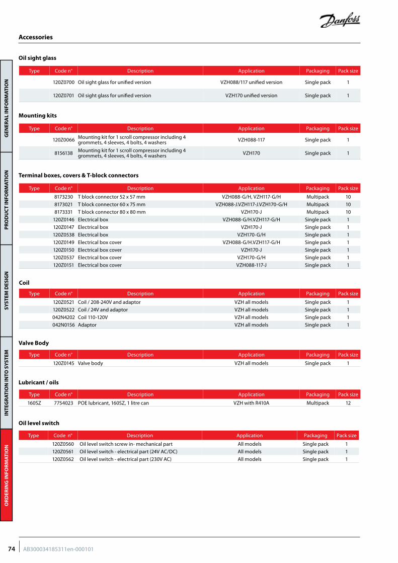
GEN
ERA
L IN
FOR
MAT
ION
PR
OD
UC
T IN
FOR
MAT
ION
SYST
EM D
ESIG
NIN
TEG
RAT
ION
INTO
SY
STEM
OR
DER
ING
INFO
RM
ATIO
N
Accessories
Type Code n° Description Application Packaging Pack size
120Z0700 Oil sight glass for unified version VZH088/117 unified version Single pack 1
120Z0701 Oil sight glass for unified version VZH170 unified version Single pack 1
Type Code n° Description Application Packaging Pack size
120Z0066 Mounting kit for 1 scroll compressor including 4 grommets, 4 sleeves, 4 bolts, 4 washers VZH088-117 Single pack 1
8156138 Mounting kit for 1 scroll compressor including 4 grommets, 4 sleeves, 4 bolts, 4 washers VZH170 Single pack 1
Oil sight glass
Mounting kits
Type Code n° Description Application Packaging Pack size
120Z0521 Coil / 208-240V and adaptor VZH all models Single pack 1
120Z0522 Coil / 24V and adaptor VZH all models Single pack 1
042N4202 Coil 110-120V VZH all models Single pack 1
042N0156 Adaptor VZH all models Single pack 1
Terminal boxes, covers & T-block connectors
Coil
Type Code n° Description Application Packaging Pack size
8173230 T block connector 52 x 57 mm VZH088-G/H, VZH117-G/H Multipack 10
8173021 T block connector 60 x 75 mm VZH088-J.VZH117-J.VZH170-G/H Multipack 10
8173331 T block connector 80 x 80 mm VZH170-J Multipack 10
120Z0146 Electrical box VZH088-G/H.VZH117-G/H Single pack 1
120Z0147 Electrical box VZH170-J Single pack 1
120Z0538 Electrical box VZH170-G/H Single pack 1
120Z0149 Electrical box cover VZH088-G/H.VZH117-G/H Single pack 1
120Z0150 Electrical box cover VZH170-J Single pack 1
120Z0537 Electrical box cover VZH170-G/H Single pack 1
120Z0151 Electrical box cover VZH088-117-J Single pack 1
Valve Body
Type Code n° Description Application Packaging Pack size
120Z0145 Valve body VZH all models Single pack 1
Type Code n° Description Application Packaging Pack size
160SZ 7754023 POE lubricant, 160SZ, 1 litre can VZH with R410A Multipack 12
Lubricant / oils
Oil level switch
Type Code n° Description Application Packaging Pack size
120Z0560 Oil level switch screw in- mechanical part All models Single pack 1
120Z0561 Oil level switch - electrical part (24V AC/DC) All models Single pack 1
120Z0562 Oil level switch - electrical part (230V AC) All models Single pack 1
74 AB300034185311en-000101
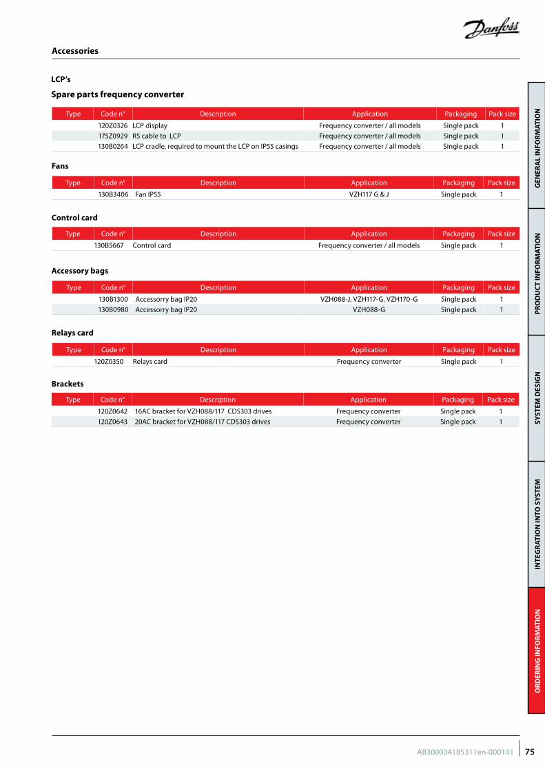
GEN
ERA
L IN
FOR
MAT
ION
PR
OD
UC
T IN
FOR
MAT
ION
SYST
EM D
ESIG
NIN
TEG
RAT
ION
INTO
SY
STEM
OR
DER
ING
INFO
RM
ATIO
N
Spare parts frequency converter
Type Code n° Description Application Packaging Pack size
120Z0326 LCP display Frequency converter / all models Single pack 1
175Z0929 RS cable to LCP Frequency converter / all models Single pack 1
130B0264 LCP cradle, required to mount the LCP on IP55 casings Frequency converter / all models Single pack 1
LCP’s
Accessories
Type Code n° Description Application Packaging Pack size
130B5667 Control card Frequency converter / all models Single pack 1
Control card
Type Code n° Description Application Packaging Pack size
130B3406 Fan IP55 VZH117 G & J Single pack 1
Fans
Type Code n° Description Application Packaging Pack size
130B1300 Accessorry bag IP20 VZH088-J, VZH117-G, VZH170-G Single pack 1
130B0980 Accessorry bag IP20 VZH088-G Single pack 1
Type Code n° Description Application Packaging Pack size
120Z0642 16AC bracket for VZH088/117 CDS303 drives Frequency converter Single pack 1
120Z0643 20AC bracket for VZH088/117 CDS303 drives Frequency converter Single pack 1
Accessory bags
Type Code n° Description Application Packaging Pack size
120Z0350 Relays card Frequency converter Single pack 1
Relays card
Brackets
75AB300034185311en-000101
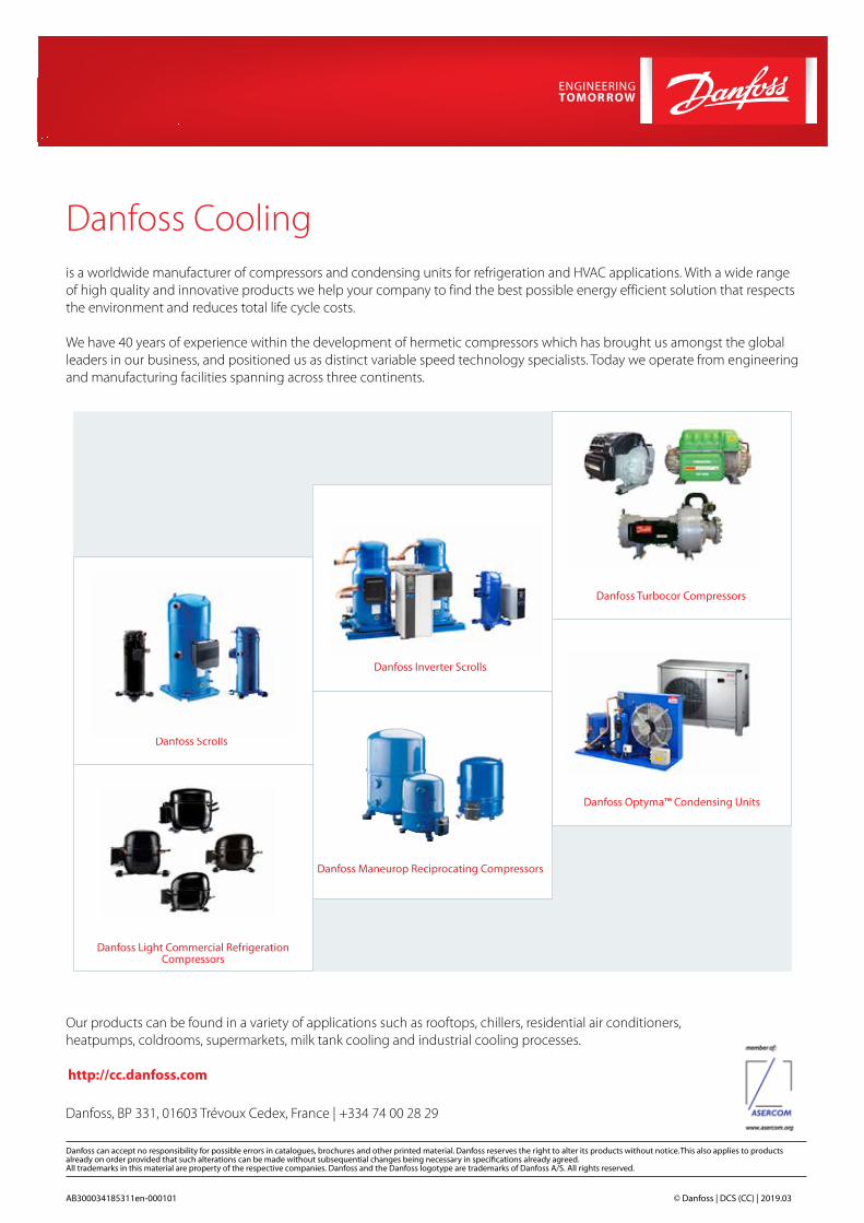
Danfoss Cooling is a worldwide manufacturer of compressors and condensing units for refrigeration and HVAC applications. With a wide range of high quality and innovative products we help your company to find the best possible energy efficient solution that respects the environment and reduces total life cycle costs.
We have 40 years of experience within the development of hermetic compressors which has brought us amongst the global leaders in our business, and positioned us as distinct variable speed technology specialists. Today we operate from engineering and manufacturing facilities spanning across three continents.
AB300034185311en-000101 © Danfoss | DCS (CC) | 2019.03
Our products can be found in a variety of applications such as rooftops, chillers, residential air conditioners, heatpumps, coldrooms, supermarkets, milk tank cooling and industrial cooling processes.
http://cc.danfoss.com
Danfoss Inverter Scrolls
Danfoss Turbocor Compressors
Danfoss Scrolls
Danfoss Optyma™ Condensing Units
Danfoss Maneurop Reciprocating Compressors
Danfoss, BP 331, 01603 Trévoux Cedex, France | +334 74 00 28 29
Danfoss Light Commercial RefrigerationCompressors