Embed Size (px)
Citation preview

TECHNICAL MANUALEDITION 1.6
VX2200 DIGITALSYSTEM

PAGE 2 of 68 VX2200 TECHNICAL MANUAL VER1.6

PAGE 3 of 68 VX2200 TECHNICAL MANUAL VER1.6
CONTENTS
PAGEManual introduction 4System introduction 4Digital door panels 5-9Digital door panel programming flow chart 7-84000 Series / 8000 Series Functional door panels 10-12Vandal resistant functional door panels (Amplifier 138) 13-14Camera’s 15Video Distribution 16Control equipment 17-23Power supplies 17Digital time clock 18-19Video switching PCB 20Isolation card 21-22Bus exchange device 22-23Concierge unit 24-26Concierge unit programming flow chart 262280 Bus interface device 27Audio telephones 28-29Audio apartment station Art.5178 30-31Videophones 32-34Video apartment station Art.5478, 5476, SL5478 35-37Vandal resistant apartment stations VR5178, VR5478 37-393600 Series Videophone (3678) 40-41Extension sounders and extension relays 42Installation directions EMI guidelines and cable guide 43-46Dip-Switch charts 46-48Troubleshooting guide 49
Wiring DiagramsOne entrance audio system 50One entrance audio system with telephones and apartment stations 51Multiple entrance audio system 52Audio with 2204N full isolation 53Audio system with concierge 542 Level audio system with main gate and multiple block entrances 55One entrance video system 56Multiple entrance video system 57Multiple entrance video with concierge 58Coax video example 592 level video system using the 2206N block exchanger 60-61Video with 2204N/316I full isolation 62
System components 63-65EMC Test results 66

PAGE 4 of 68 VX2200 TECHNICAL MANUAL VER1.6
MANUAL INTRODUCTIONThe information in this manual is intended as an installation and commissioning guide for the VX2200 Digitalsystem. This manual should be read carefully before the installation commences. Any damage caused to theequipment due to faulty installations where the information in this manual has not been followed is not theresponsibility of Videx Security Ltd.
VIDEX run free training courses for engineers who are not familiar with the Videx product range. Technicalhelp is also available on 0191 224 3174 during office hours or via e-mail [email protected].
SYSTEM INTRODUCTIONThe VX2200 audio system is based on a “2 wire” BUS for audio systems and a “6 wire” bus for videosystems. The digital front panels are available in several versions including the 8000 series design (Witheither alphanumeric A-H feature or Name scroll feature), 4000 series design (With either alphanumeric A-Ffeature or Name scroll feature) and vandal resistant with optional alpha buttons A-H. All digital panels havethe facility to call up to 998 users (when using 2206N bus exchange devices, 180 per block/bus). Digitalpanels also benefit from each user having the additional feature of a personal access code to gain access tothe building. Functional panels are also available with up to 64 buttons. All intercom telephones areaddressed by means of an 8 way dip-switch located within each handset.
PAGE 5 of 68 VX2200 TECHNICAL MANUAL VER1.6
316x
B A B A
DIGITAL PANELS
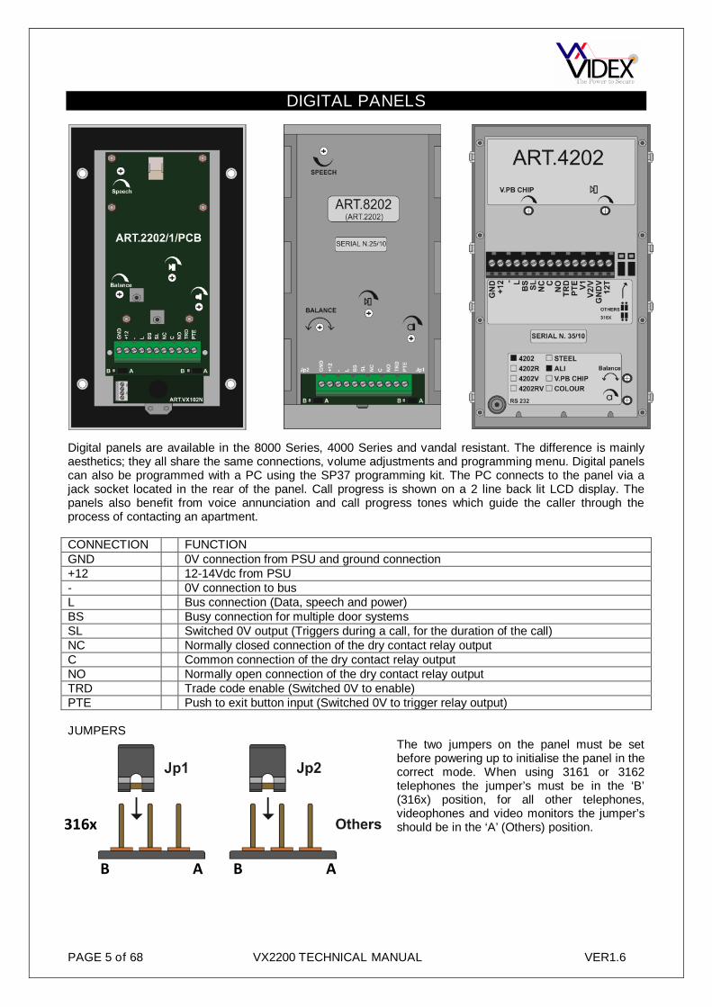
Digital panels are available in the 8000 Series, 4000 Series and vandal resistant. The difference is mainlyaesthetics; they all share the same connections, volume adjustments and programming menu. Digital panelscan also be programmed with a PC using the SP37 programming kit. The PC connects to the panel via ajack socket located in the rear of the panel. Call progress is shown on a 2 line back lit LCD display. Thepanels also benefit from voice annunciation and call progress tones which guide the caller through theprocess of contacting an apartment.
CONNECTION FUNCTIONGND 0V connection from PSU and ground connection+12 12-14Vdc from PSU- 0V connection to busL Bus connection (Data, speech and power)BS Busy connection for multiple door systemsSL Switched 0V output (Triggers during a call, for the duration of the call)NC Normally closed connection of the dry contact relay outputC Common connection of the dry contact relay outputNO Normally open connection of the dry contact relay outputTRD Trade code enable (Switched 0V to enable)PTE Push to exit button input (Switched 0V to trigger relay output)
JUMPERSThe two jumpers on the panel must be setbefore powering up to initialise the panel in thecorrect mode. When using 3161 or 3162telephones the jumper’s must be in the ‘B’(316x) position, for all other telephones,videophones and video monitors the jumper’sshould be in the ‘A’ (Others) position.

PAGE 6 of 68 VX2200 TECHNICAL MANUAL VER1.6
VOLUME ADJUSTMENTThere are four volume adjusters on the door panel as follows:-
Speaker volume Microphone volume Balance between mic Voice annunciationvolume and speaker volume (May also bevolume labelled ‘V.PB CHIP’
MAKING A CALLAll stages of the call will be acknowledged via the LCD display, voice annunciation and call progress tones.Additionally, the panel will also prompt the user with information on how to progress to the next stage of thecall. To make a call simply enter the apartment number required and press ‘Enter’. Alternatively, if the panelhas the scroll buttons (‘’,’’,’’) use the ‘’, ‘’ to locate the apartment to call then press ‘’.
USING THE TRADEOn the 4000 Series and 8000 Series panels thetrade feature can only be used with a code. To usethis facility first the TRD connection must to shortedto ground (As shown in the diagram to the right).To enter a trade code the panel must be instandby. Press the clear button (Display will show‘TRADE C’), enter the code and then press ‘Enter’.
On the vandal resistant panel the trade button can be used as described above or alternatively the tradebutton can be used to simply release the door when the button is pressed (As long as the time clock isactive). See diagram below for wiring these options.
WITHOUT CODE WITH CODE
USING AN ACCESS CODE AND ENTERING PROGRAMMING MODEOn panels with a ‘CODE’ button, press ‘CODE’ followed by the code and press ‘Enter’. For panels without a‘CODE’ button, press ‘0’ followed by the code and press ‘Enter’
Technical specificationsMemory capacity : 998 usersWorking voltage : 13 Vdc +/- 10%Max. absorption : about 350 mAWorking temperature : -10 +50 C°Relay contacts : 3A@30Vdc, 3A@120Vac

PAGE 7 of 68 VX2200 TECHNICAL MANUAL VER1.6
DIGITAL PANEL PROGRAMMING
ENTER PRESET FACTORYCODE 0+6x1 (0111111) CODE : ****** CODE : ******
ENTER MASTER CODE(1 to 6 digits)
CODE : ******NEW : ****
CODE : ******NEW : ****
PRESS ‘ENTER’ BUTTON
(*) NOTE 2
ENTER TRADE CODE(1 to 6 digits)
TRADE C : xxxxxxNEW : xxxx
TRADE C :NEW : 1234
PRESS ‘ENTER’ BUTTON
(*) NOTE 2
ENTER MEMORYLOCATION (1 to 998) MEM.LOCATION: xxx MEM.LOCATION: 15
PRESS ‘ENTER’ BUTTON
(*) NOTE 4
ENTER FLAT NUMBER(1 to 6 Digits)
FLAT :NEW : xxxxxx
FLAT :NEW : 15
PRESS ‘ENTER’ BUTTON
(*) NOTE 1-2
ENTER PHONE IDADDRESS (1 to 180)
ID PHONE :NEW : xxx
ID PHONE :NEW : 15
PRESS ‘ENTER’ BUTTON
ENTER CODE TO OPENDOOR (1 to 6 Digits)
DOOR CODE :NEW : xxxxxx
DOOR CODE :NEW : 1066
PRESS ‘ENTER’ BUTTON
(*) NOTE 1-2
ENTER BLOCK NUMBER(1 to 15)
2206N N. : 0NEW : xx
2206N N. :NEW : 1
PRESS ‘ENTER’ BUTTON
(*) NOTE 5
ENTER USER NAME USER NAME :
xxxxxxxxxUSER NAME :HOGART STEVE
PRESS ‘ENTER’ BUTTON
(*) NOTE 6
MOREFLATS?
YES
NO
MEM.LOCATION:
PRESS ‘ENTER’ TWICE
INSERT SPEECH TIME(1 to 255 Seconds)
SPEECH TIME : xxxNEW : xxx
SPEECH TIME :NEW: 120
(*) NOTE 2
INSERT DOOR TIME(1 to 255 Seconds)
DOOR TIME :NEW : xxx
DOOR TIME :NEW : 5
PRESS ‘ENTER’ BUTTON
(*) NOTE 2
ENTER DEVICE NO.(1 to 15)
DEVICE Nr. : xxNEW : xx
DEVICE Nr. :NEW : 1
PRESS ‘ENTER’ BUTTON
(*) NOTE 2
LCD DISPLAY EXAMPLE
SET LANGUAGE.(0 to 5)
0=ENG 1=IT 2=ESP3=POR 4=FR 5=GER
0=ENG 1=IT 2=ESP3=POR 4=FR 5=GER
PRESS ‘ENTER’ BUTTON
CONTINUED ON NEXT PAGE
PAGE 8 of 68 VX2200 TECHNICAL MANUAL VER1.6
NOTES:-
SET SPEECH PLAYBACK(0 to 2)
0=NO 1=ST 2=CMBSPEECH BOARD
0=NO 1=ST 2=CMBSPEECH BOARD
SELECT 0 - 5
CONTINUED FROM PREVIOUS PAGE
MASTER/SLAVE SETTING(0 = SLAVE, 1=MASTER)
MASTER : NOT1 = YES
MASTER : YES0 = NOT
SELECT 0 - 2
(*) NOTE 2-3
AUTOMATIC FLAT TEST(1 or ENTER)
1 = TEST FLAT“ENTER” = END
TEST FLAT 101ID PG 1-1 OK
SELECT 0 or 1
SYSTEM READY TO USE ENTER FLAT NR.- SEARCH -
ENTER FLATNUMBER
SELECT 1 or ENTER
(*) NOTE 2-3
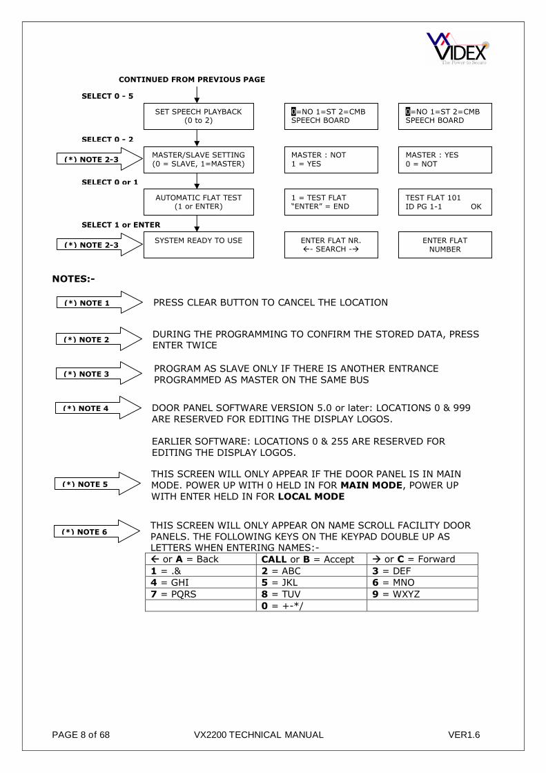
(*) NOTE 1 PRESS CLEAR BUTTON TO CANCEL THE LOCATION
(*) NOTE 2DURING THE PROGRAMMING TO CONFIRM THE STORED DATA, PRESSENTER TWICE
(*) NOTE 3PROGRAM AS SLAVE ONLY IF THERE IS ANOTHER ENTRANCEPROGRAMMED AS MASTER ON THE SAME BUS
(*) NOTE 4 DOOR PANEL SOFTWARE VERSION 5.0 or later: LOCATIONS 0 & 999ARE RESERVED FOR EDITING THE DISPLAY LOGOS.
EARLIER SOFTWARE: LOCATIONS 0 & 255 ARE RESERVED FOREDITING THE DISPLAY LOGOS.
(*) NOTE 5
THIS SCREEN WILL ONLY APPEAR IF THE DOOR PANEL IS IN MAINMODE. POWER UP WITH 0 HELD IN FOR MAIN MODE, POWER UPWITH ENTER HELD IN FOR LOCAL MODE
(*) NOTE 6THIS SCREEN WILL ONLY APPEAR ON NAME SCROLL FACILITY DOORPANELS. THE FOLLOWING KEYS ON THE KEYPAD DOUBLE UP ASLETTERS WHEN ENTERING NAMES:- or A = Back CALL or B = Accept or C = Forward
1 = .& 2 = ABC 3 = DEF4 = GHI 5 = JKL 6 = MNO
7 = PQRS 8 = TUV 9 = WXYZ
0 = +-*/
PAGE 9 of 68 VX2200 TECHNICAL MANUAL VER1.6
DIGITAL PANEL MODEThe digital panel can be set to either MAIN MODE or LOCAL MODE. MAIN mode should only be used forpanels that call all users and on systems that include 2206N devices (One per block or one for every 180apartments), use LOCAL mode for all other applications. To set a digital panel as MAIN MODE, power upwith the 0 button pressed. To set as LOCAL MODE, power up with ENTER pressed (The mode can also bechanged via the PC programming software.To use the digital front panel with 3000 series intercoms and videointercoms, press the “ENTER” buttonwhile powering up and wait until the display shows the message “S3000”, release the button.To use the digital front panel with 900 series intercoms and videointercoms, press the “CLEAR” button whilepowering up and wait until the display shows the message “S900”, release the button.
Additional programming notesa. During the programming of the master door panel, all slave door panels will be off line. (This
inconvenience does not occur if the slave entrances are connected through Art.2206 on a separate bus);b. If the programming of the MASTER device is wrong (Eg. Programmed as a SLAVE when it should be a
MASTER), an error condition takes place signalled by the message “ERROR!” on the display. To recoverfrom this situation keep the “0” button pressed until the display shows CODE. Perform the programmingagain correcting the error. Alternatively programming a SLAVE as a MASTER can cause feedback(Larsen effect) during the conversation (Only one master per level per block allowed).
c. The entering of values not admitted is signalled by an error message, the unit waits for a valid entrybefore continuing on with the programming.
d. Pressing the “CLEAR” button, at any stage will clear the current data previously entered.
e. To enter a number to call the concierge (if present) while the concierge is in night mode, combine the“flat number” (Concierge number) with the “ID PHONE” address n.1.
f. When using the door panel in MAIN MODE, the programming of each user will require the address of the2206N (Block address) for which that user is connected.

PAGE 10 of 68 VX2200 TECHNICAL MANUAL VER1.6
316x
4000 SERIES/8000 SERIES FUNCTIONAL PANELS
4203 4283 8203
The 4000 and 8000 Series functional panels are of modular design each being capable of expansion up to64 call buttons (only 32 buttons on the 4283 combined camera and speaker module). Programming optionsare carried out via dip-switches. Call progress tones are used to indicate the status of a call.
CONNECTION FUNCTIONGND 0V connection from PSU and ground connection+12 12-14Vdc from PSU- 0V connection to busL Bus connection (Data, speech and power)BS/BSY Busy connection for multiple door systemsSL Switched 0V output (Triggers during a call, for the duration of the call)NC Normally closed connection of the dry contact relay outputC Common connection of the dry contact relay outputNO Normally open connection of the dry contact relay outputPTE Push to exit button input (Switched 0V to trigger relay output)V1 +Sync of balanced video signal from camera (4283 only)V2/V - Sync of balanced video signal from camera (4283 only) When in coax mode used as
video signal, screen of coax connects to GND
MAKING A CALLPress the relevant button: 5 quick beeps will indicate if the system is busy, otherwise the call will be signalledby a slow intermittent acoustic signal until the call is answered, the conversation time expires (programmabletime) or the call is interrupted by pressing a push button for a minimum of 2 seconds. A short intermittentacoustic signal indicates that the door is open. If a wrong push button is pressed or if there is no answer, anew call will erase the previous one.
JUMPERSThe two jumpers on the 4203 & 8203 panelmust be set before powering up to initialise thepanel in the correct mode. When using 3161 or3162 telephones the jumper’s must be in the‘316x’ position, for all other telephones,videophones and video monitors the jumper’sshould be in the ‘Others’ position.
There are also three jumpers on the 4283 module which set the lock output to either dry contact (C, NO &NC) or voltage output (Lock connects across GND and NO, NO being a 12Vdc output) and the other two areused to select the video output to be either balanced or composite.

PAGE 11 of 68 VX2200 TECHNICAL MANUAL VER1.6
VOLUME ADJUSTMENTThere are three volume adjusters on the door panel as follows:-
Speaker volume Microphone volume
CONNECTING ADDITIONAL BUTTONSUp to 64 buttons (32 on the 4283) can be connected to themodules using an X-Y matrix as shown here.
When using the 4000 Series button modules you will notice anumber of jumpers on these modules which allow you to select ifthe buttons are common or isolated from each other.
DIP SWITCHES (4203 & 8203)All DIP-SWITCH CHANGES MUST BE CONFIRMED BY POWERING DOWN THE MODULE AND THEN POWERING UP AGAIN.
Switch 1 sets the panel as a Master or Slave. One master required on each bus.
Switches 2 & 3 define the range ofPhone IDs generated by the unitwhen the call buttons are pressed.For example with dip-switch 2 and3 both OFF, the push buttonconnected between terminals “1”
and “a” calls ID PHONE 1 while the same push button, with dip-switch 2 ON and dip-switch 3 OFF, will callPHONE ID 65.
Switch 4 sets the maximum conversation time.
Switch 5 sets the relay operation time.
Switches 6, 7 & 8 set the panels ID. This is required on video systemsand systems that include a concierge as it allows an apartment or theconcierge to recall the panel to activate the camera, switch on the audioand also identifies to the concierge which panel a call originates.
Nr.1 Setting UpOFF = SlaveON = Master (default)
Nr.2 Nr.3 SettingsOFF OFF from buttons 1 to 64ON OFF from buttons 65 to 128OFF ON from buttons 129 to 180ON ON from buttons 1 to 64 with 900 series devices
Nr.4 Setting UpOFF = 1 minON = 2 min
Nr.5 Setting UpOFF = 2 secondsON = 6 seconds
Nr.6 Nr.7 Nr.8 Setting UpOFF OFF OFF = 1ON OFF OFF = 2OFF ON OFF = 3ON ON OFF = 4OFF OFF ON = 5ON OFF ON = 6OFF ON ON = 7ON ON ON = 8
Balance betweenmicrophone volume andspeaker volume

PAGE 12 of 68 VX2200 TECHNICAL MANUAL VER1.6
DIP SWITCHES (4283)All DIP-SWITCH CHANGES MUST BE CONFIRMED BY POWERING DOWN THE MODULE AND THEN POWERING UP AGAIN.
Switch 1 sets the panel as a Master or Slave. One master required on each bus.
Switches 2, 3 & 4 define the range of Phone IDs generatedby the unit when the call buttons are pressed. For examplewith dip-switch 2, 3 and 4 OFF, the push button connectedbetween terminals “1” and “a” calls ID PHONE 1 while thesame push button, with dip-switch 2 ON and dip-switch 3& 4 OFF, will call PHONE ID 33.
Switch 5 sets the maximum conversation time.
Switch 6 sets the relay operation time.
Switches 7, 8 & 9 set the panels ID. This is required on video systemsand systems which include a concierge as it allows an apartment or theconcierge to recall the panel to activate the camera and also identifies tothe concierge which panel a call is coming from.
Switch 10 not used.
Programming notesIn case of a wrong Master/Slave configuration (Dip-switch no.1), the following problems can occur:a. if the unit should be a Master but is configured as a Slave, the error is signalled by an acoustic
intermittent signal until the problem is resolved;b. if the unit should be Slave but is configured as Master, the impedance of the system will have a lack of
balance, causing feedback (“Larsen” effect).When a system includes a concierge unit, the push button combined with the Phone ID 1 will call to theconcierge regardless of if the concierge is in day or night mode.
MODULE BUTTON WIRING COLOUR CODE:-Colour Buttonblue Buttons Commonyellow Button 1red Button 2white Button 3 (4000 Series only)black Button 4 (4000 Series only)
Technical specificationsWorking voltage : 13 Vdc +/- 10%Max. absorption : approx 350 mAWorking temperature : -10 +50 C°Relay contacts : 3A@30Vdc, 3A@120Vac
Nr.1 Setting UpOFF = SlaveON = Master (default)
Nr.2 Nr.3 Nr.4 SettingsOFF OFF OFF from buttons 1 to 32ON OFF OFF from buttons 33 to 64OFF ON OFF from buttons 65 to 96ON ON OFF from buttons 97 to 128OFF OFF ON from buttons 129 to 160ON OFF ON from buttons 161 to 180OFF ON ON from buttons 1 to 32
(900 Series phones)ON ON ON from buttons 33 to 64
(900 Series phones)
Nr.5 Setting UpOFF = 1 minON = 2 min
Nr.6 Setting UpOFF = 2 secondsON = 6 seconds
Nr.7 Nr.8 Nr.9 Setting UpOFF OFF OFF = 1ON OFF OFF = 2OFF ON OFF = 3ON ON OFF = 4OFF OFF ON = 5ON OFF ON = 6OFF ON ON = 7ON ON ON = 8
CALL PROGRESS LED’SSymbol LED meaning
The first LED (red), indicates that it is not possible to make acall because a call or a conversation is in progress (from theoutdoor station from which you are calling or from anotheroutdoor station on systems with multiple entrances).
The second LED (red), indicates that a call is in progress.The LED will switch OFF when the call is answered.
The third LED (yellow), indicates the call has beenanswered. The LED will switch OFF at the end of theconversation.The fourth LED (green), indicates that the door lock hasbeen released. It will switch OFF at the end of the “dooropening” time.

PAGE 13 of 68 VX2200 TECHNICAL MANUAL VER1.6
VANDAL RESISTANT FUNCTIONAL PANELS
This module is used in the VX2200 2 wire audio, 6 wire video functionalvandal resistant door panels and includes all features required for audio &video installations. A 13.8Vdc PSU is required to power this system. Up to23 buttons can be connected to this module. (This module cannot be usedwith 316x phones).
MAKING A CALLPress the relevant button: 5 quick beeps will indicate if the system is busy,otherwise the call will be signalled by a slow intermittent acoustic signaluntil the call is answered, times out or the call is interrupted by pressing apush button for more than 2 seconds. A short intermittent acoustic signalindicates that the door is open. A yellow LED indicates conversation hasbegun and a green LED indicates relay activation.
CONNECTION FUNCTIONNC Normally closed connection of relayC Common connection of relayNO Normally open connection of relayPTE Push to exit button input (Switch to 0V)SL Switched 0V output (0V during a call for video power supply switching)BS Busy signal to other panels (12Vdc in standby, 0V during a call)L Bus connection approx. 7.5Vdc- 0V for bus+12 12Vdc input to power the amplifier- 0V from PSU
VOLUME ADJUSTMENTThere are three volume adjusters on the door panel as follows:-
Speaker volume Microphone volume
CONNECTING ADDITIONAL BUTTONSUp to 23 buttons can be connected to the modules using an X-Ymatrix and the wiring harness as shown here.
Factory resetTo revert to factory default settings as shown in ( ) below, power down the 138 amplifier short PTE toground, power up and await 6 beeps, remove the short.
ProgrammingThere are several features of the amplifier that can be programmed into non-volatile memory. Entering eachprogramming stage requires the shorting of certain connections on the button matrix using the connectors 5& 6 labelled above. Remove the plug from connector ABCD so that the connectors 5 or 6 can be connectedto the relevant pin as outlined in the tables below. Beeps are used to indicate the new setting as outlined inthe tables below. The procedure to program these settings is as follows:-
Balance betweenmicrophone volume andspeaker volume

PAGE 14 of 68 VX2200 TECHNICAL MANUAL VER1.6
1. Power down the 138 amplifier2. Connect the plug (5 or 6) to A,B,C or D depending on the setting to program as outlined below.3. Power up the 138 amplifier4. Listen to the beeps from the 138 amplifier, When the correct number is reached as outlined below,
remove the link between the plug and A,B,C or D.5. A long confirmation beep will confirm the new setting has been stored.
DEFAULTS ARE SHOWN IN ( )
MASTER or SLAVESet amplifier as master or slave (Each system requires one master, any additional door’s on a system mustbe set to slave).
Power up with wires 5 & A shorted. Wait for correct beeps then remove short.1 BEEP 2 BEEPS(Master) Slave
BANK of BUTTONSSet the bank of buttons relevant to the button matrix (For most systems this will be buttons 1-23 but for largersystems it may be necessary to have the buttons start at 25 through to 47, i.e. Button 1A would call address25 as oppose to 1).
Power up with wires 5 & B shorted. Wait for correct beeps then remove short.1 BEEP 2 BEEPS
(Button addresses 1 – 23) Button addresses 25-47
MAXIMUM CALLING TIME BEFORE ANSWERSet the maximum length of a call ‘wait to answer’ before the call is cleared down. This does not affect theconversation time which can be programmed separately.
Power up with wires 5 & C shorted. Wait for correct beeps then remove short.1 BEEP 2 BEEPS 3 BEEPS 4 BEEPS 5 BEEPS
10 Seconds 20 Seconds 30 Seconds (40Seconds) 50Seconds
6 BEEP 7 BEEPS 8 BEEPS 9 BEEPS 10 BEEPS60 Seconds 70 Seconds 80 Seconds 90Seconds 100Seconds
CONVERSATION TIMESet the maximum length of a conversation before the call is automatically cleared down.
Power up with wires 5 & D shorted. Wait for correct beeps then remove short.1 BEEP 2 BEEPS 3 BEEPS 4 BEEPS 5 BEEPS
20 Seconds 40 Seconds (60 Seconds) 80 Seconds 100 Seconds
6 BEEP 7 BEEPS 8 BEEPS 9 BEEPS 10 BEEPS120 Seconds 140 Seconds 160 Seconds 180 Seconds 200 Seconds
RELAY TIMEDoor open relay time
Power up with wires 6 & A shorted. Wait for correct beeps then remove short.1 BEEP 2 BEEPS 3 BEEPS 4 BEEPS 5 BEEPS
2.5 Seconds (5 Seconds) 7.5 Seconds 10 Seconds 12.5 Seconds
6 BEEP 7 BEEPS 8 BEEPS 9 BEEPS 10 BEEPS15 Seconds 17.5 Seconds 20 Seconds 22.5 Seconds 25 Seconds
DEVICE NUMBERIt is very important on video systems and systems with a concierge that each door panel amplifier has aunique device number.
Power up with wires 6 & B shorted. Wait for correct beeps then remove short.1 BEEP 2 BEEPS 3 BEEPS 4 BEEPS 5 BEEPS
(Device 1) Device 2 Device 3 Device 4 Device 5
6 BEEP 7 BEEPS 8 BEEPS 9 BEEPS 10 BEEPSDevice 6 Device 7 Device 8 Device 9 Device 10

PAGE 15 of 68 VX2200 TECHNICAL MANUAL VER1.6
CAMERA MODULES
All camera modules are availablein mono or colour. The monocameras include infra-redillumination to illuminate a subjectin poor lighting conditions (maxrange 80cm). The colour camerasinclude white LED’s which switchon during a call. With theexception of the 830 and 830NC,the cameras are all able to supportboth balanced and compositevideo outputs which is selectable,adjusting the position of thejumpers. The 4000, 8000 and VR
cameras all include a ball joint camera swivel allowing the camera direction to be adjusted 10° in anydirection.
CONNECTION FUNCTIONI, + Switched +20Vdc Input to power cameraF1, - 0V power to cameraV Composite video output (Coax centre core)M Screen of coaxV1 +Sync balanced video connectionV2 - Sync balanced video connectionSB, SB1, SB2 Heater connectionsG Ground12VI Alternate 12Vdc supply (Used instead of 20Vdc into I
JUMPERSOn camera’s which include jumpers these should be set according to the type of video signal used. If thevideo signal and cable type is composite with coax cable then ensure all jumpers are towards the ‘COAX’position. Alternatively if the video is a balanced signal using twisted pair cable then ensure the jumpers areall set to NC (Non Coax).

PAGE 16 of 68 VX2200 TECHNICAL MANUAL VER1.6
VIDEO DISTRIBUTION
COAX VIDEOThe version to the left is theArt.894 and the version to theright is the 894I. Both versionsare 4 way video splitterstherefore one is required forevery four videophones.
The 894I also benefits from overcurrent protection for each of the four 20V (500mA max) outputs meaning, if a shortappears on those connections or a fault towards the monitor occurs then the 20V tothat output will be disconnected to allow all other outputs to continue working. The redLED next to the output will illuminate to show the problem output.
CONNECTION FUNCTIONVin, V Video in from previous video distributor, control cabinet or cameraM Coax cable screenVout, V Video out to next video distributor or end of line termination.V1, V2, V3, V4 Video output to four videophones (4 outputs)+12 12V input to power the video distributor (Powered from videophones)+20 20Vdc feed through from video power supply to monitors (894I only)0V 0V feed through from video power supply to monitors (894I only)
NON-COAX (BALANCED VIDEO)
The version to the left is theArt.316 and the version to theright is the 316I. Both versions are4 way video splitters thereforeone is required for every fourvideophones.
The 316I also benefits from overcurrent protection for each of the four 20V (500mA max) outputs meaning, if a shortappears on those connections or a fault towards the monitor occurs then the 20V tothat output will be disconnected to allow all other outputs to continue working. The redLED next to the output will illuminate to show the problem output. Each 316I/316draws 5mA in standby.
CONNECTION FUNCTIONV1 + Sync balanced video in from previous video distributor, control cabinet or cameraV2 - Sync balanced video in from previous video distributor, control cabinet or cameraV1a, V1b, V1c,V1d
+ Sync video output to videophone (4 Outputs)
V2a, V2b, V2c,V2d
- Sync video output to videophone (4 Outputs)
+20, + 20Vdc feed through to monitors and power from video power supply0V, - 0V feed through from video power supply to monitors
END OF LINEOn coax video systems it is necessary to terminate any unused outputs with a 75Ω resistor. This is achieved on the 894 by fitting a 75Ω resistor across Vn and M of the unused outputs. On the 894I there are jumpers next to each output which should be closed if the output is not used and open if it is. Additionally it is alsonecessary to fit an end of line resistor across Vout & M of the last video distributor (Both coax and non-coaxversions) to terminate the end of the line. Again on the 894I/316I there is a jumper(s) which should be closedon the last unit instead of fitting a resistor (Labelled EOL on the 894I and End of line on the 316I).

PAGE 17 of 68 VX2200 TECHNICAL MANUAL VER1.6
CONTROL EQUIPEMENT
As there are many variationsof control cabinet available(Audio, video, with isolation,multiple door etc). Thecomponents that make up acontrol cabinet are listedbelow:-
13.8Vdc SYSTEM PSU
Battery backup is a standardfeature of these PSU’s. Werecommend a 7Ah sealed leadacid battery. 1A, 2A, 3A & 4APSU’s are normally used on thissystem, all of which have aregulated output voltage of13.8Vdc. DC out and battery trickle charge are independently fused.Additionally the 4A PSU includes a fan out PCB which shares theavailable 4A’s between 4 independently fused outputs. Thecombination of these fuse values can be anything as long as the 4outputs are fused to no more than 4A. Fuse values are as follows:-
PSU MAINS FUSE DC OUT FUSE BATTERY TRICKLE CHARGEFUSE
2 Amp T315mA F2.0A T315mA3 Amp T630mA F3.0A T315mA4 Amp T3.15A Main fuse F4.0A. Fan out
fuses can be anycombination up to a total of4A
T1A
20Vdc VIDEO PSU
The Art.893N1 is a 1A pulse, 800mA continuous20Vdc PSU. It is a switched output supplyrequiring either a positive trigger on terminal ‘+C’or a negative trigger on ‘-C’ to switch the 20Vdcoutput on. There are no fuses in this PSU. If thereis a short on the output or an over current situationthen the PSU will shut down until the problem isresolved.
CONNECTION FUNCTION-C 0V trigger to activate output+C +8-30Vdc to activate output- 0V output connection+ 20Vdc output connection+D 20Vdc output via diode

PAGE 18 of 68 VX2200 TECHNICAL MANUAL VER1.6
TIME CLOCK
The 701T is a BST/GMT time clock with 6 programmable on/offperiods and two modes of operation. The first mode being astandard time clock mode whereby the dry contact relay outputtriggers for the length of an on/off period. The second mode isknown as the trade button mode and only operates the relay whenthe trade input is triggered and during an active on/off period. Therelay would then stay energised for a programmed time (01-99seconds).
CONNECTION FUNCTION+ 12Vdc power supply input- 0V power supply connectionTR Trade button input (Shorts to 0V)C Common connection of dry contact relay outputNO Normally open connection of dry contact relay outputNC Normally closed connection of dry contact relay output
JUMPERSThe jumper in the top right selects the time clocks mode of operation.A = TRADE BUTTON MODEB = TIME CLOCK MODE
The jumper in the middle Enables/Disables automatic BST/GMT time correctionA = AUTOMATIC ADJUSTMENT DISABLEDB = AUTOMATIC ADJUSTMENT ENABLED
The time clock includes a battery to maintain the time while the time clock isn’t powered.The battery should maintain the time and settings for a minimum of 3 months.ON = BATTERY ENABLEDOFF = BATTERY DISABLED (Should be moved to ON when installed)
TECHNICAL SPECIFICATIONSupply Voltage : 12V DC or 12V ACStandby Current (Relay off) : 47mAStandby Current (Relay on) : 67mABattery backup : Min. 3 MonthsRelay contacts (Dry contact) : 3A @ 24V DC
3A @ 120V ACOn/Off times available : Six
: ON/OFF period 1 will switch off at the off time for that periodregardless of manual override.
: ON/OFF period 2-6 will Not switch off at the off time for that period ifmanual override is pressed.
Trade mode relay time : From 1 second to 99 secondsDimensions : 110mm x 70mm x 30mm
PAGE 19 of 68 VX2200 TECHNICAL MANUAL VER1.6
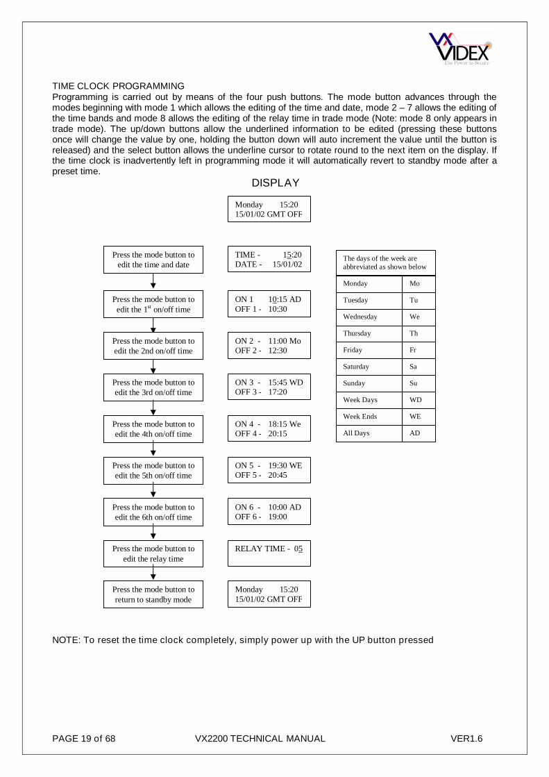
TIME CLOCK PROGRAMMINGProgramming is carried out by means of the four push buttons. The mode button advances through themodes beginning with mode 1 which allows the editing of the time and date, mode 2 – 7 allows the editing ofthe time bands and mode 8 allows the editing of the relay time in trade mode (Note: mode 8 only appears intrade mode). The up/down buttons allow the underlined information to be edited (pressing these buttonsonce will change the value by one, holding the button down will auto increment the value until the button isreleased) and the select button allows the underline cursor to rotate round to the next item on the display. Ifthe time clock is inadvertently left in programming mode it will automatically revert to standby mode after apreset time.
DISPLAY
NOTE: To reset the time clock completely, simply power up with the UP button pressed
Press the mode button toedit the time and date
Monday 15:2015/01/02 GMT OFF
TIME - 15:20DATE - 15/01/02
ON 1 10:15 ADOFF 1 - 10:30
ON 5 - 19:30 WEOFF 5 - 20:45
ON 3 - 15:45 WDOFF 3 - 17:20
ON 4 - 18:15 WeOFF 4 - 20:15
ON 2 - 11:00 MoOFF 2 - 12:30
ON 6 - 10:00 ADOFF 6 - 19:00
RELAY TIME - 05
Press the mode button toedit the 1st on/off time
Press the mode button toedit the 2nd on/off time
Press the mode button toedit the 3rd on/off time
Press the mode button toedit the 4th on/off time
Press the mode button toedit the 5th on/off time
Press the mode button toedit the 6th on/off time
Press the mode button toedit the relay time
Monday
Tuesday
Wednesday
Thursday
Friday
Saturday
Sunday
Week Days
Week Ends
All Days
Mo
Tu
We
Th
Fr
Sa
Su
WD
WE
AD
The days of the week areabbreviated as shown below
Monday 15:2015/01/02 GMT OFF
Press the mode button toreturn to standby mode

PAGE 20 of 68 VX2200 TECHNICAL MANUAL VER1.6
VX123 VIDEO SWITCHING PCB
The VX123 is used on multiple door video systems to switch thevideo from a single door to the bus. Each PCB can control up tofour video panels. Multiple PCB’s can be used to expand thesystem. A green LED indicates when a panel is connected to thebus.
CONNECTION FUNCTIONGND 0V+12 12Vdc from PSU to power the PCB+20 20Vdc switched to the relevant door when triggeredV1 + Sync video signal switched to relevant door when triggeredV2 - Sync video signal switched to relevant door when triggeredSL Trigger input to activate a channel (Switched 0V)
4 WAY ISOLATION PCB (2204N)The 2204N will protect against shorts or faults on all connections to an apartment. Plug in connections areused for easy maintenance. The 2204N can also be connected as a bus in a prewired cabinet and isaddressed using a 6 way dip-switch bank. For video systems there is an additional video isolation card (316Ifor non-coax or 894I for coax) which piggy backs this board and includes all the additional connections forvideo. There are 10 LED’s on each card which can be used to identify when a channel is in use (Greenchannel LED on) and to indicate a variety of faults such as shorts on +12V out, short on bus and S1permanently active.
Six way connectors – Main bus in/out Five way connectors – Four outputs to
apartments.
Connection Function- 0VL Bus connection12V +12VdcD Door open LED (Switched 12V)S1 Spare service button on telephone
(Switched 0V)
LED FunctionD1 Bus fault output 1D8 Bus fault output 2D14 Bus fault output 3D19 Bus fault output 4D7 Output 1 activeD6 Output 2 activeD5 Output 3 activeD4 Output 4 activeD21 S1 service switch activeD3 12V out fault on one of the outputs

PAGE 21 of 68 VX2200 TECHNICAL MANUAL VER1.6
OPERATIONIn stand-by the phones connected to the 2204N are physically disconnected from the main BUS. During acall the selected channel will be connected to the main bus, the green LED next to the channel will illuminatefor the length of the call.
PROGRAMMING (DIP-SWITCHES)The dip-switches are used to address the PCB. The address of the PCB must correspond with the addressof the telephone in the apartment. For example, output 1 of the first 2204N must be connected to atelephone with address 1, output 3 must be connected to a telephone with address 3, Output 1 of the second2204N must be connected to a telephone with address 5 etc. The table below shows all availableaddresses.
Addresses of: Addresses of: Addresses of:
2204 no.
DIP-SWSettings
Connected Intercoms
2204 No.DIP-SWSettings
Connected Intercoms
2204 No.
DIP-SWSettings
Connected Intercoms
L1 L2 L3 L4 L1 L2 L3 L4 L1 L2 L3 L4
0 1 2 3 4 16 65 66 67 68 32 129 130 131 132
1 5 6 7 8 17 69 70 71 72 33 133 134 135 136
2 9 10 11 12 18 73 74 75 76 34 137 138 139 140
3 13 14 15 16 19 77 78 79 80 35 141 142 143 144
4 17 18 19 20 20 81 82 83 84 36 145 146 147 148
5 21 22 23 24 21 85 86 87 88 37 149 150 151 152
6 25 26 27 28 22 89 90 91 92 38 153 154 155 156
7 29 30 31 32 23 93 94 95 96 39 157 158 159 160
8 33 34 35 36 24 97 98 99 100 40 161 162 163 164
9 37 38 39 40 25 101 102 103 104 41 165 166 167 168
10 41 42 43 44 26 105 106 107 108 42 169 170 171 172
11 45 46 47 48 27 109 110 111 112 43 173 174 175 176
12 49 50 51 52 28 113 114 115 116 44 177 178 179 180
13 53 54 55 56 29 117 118 119 120
14 57 58 59 60 30 121 122 123 124
15 61 62 63 64 31 125 126 127 128
Technical specificationsNumber of outputs : 4Addressing range : from 0 to 44Working temperature : -10 +50 C°12V output current max. : 200mAStandby current : 12mA (With 4 phones connected to L & -)

PAGE 22 of 68 VX2200 TECHNICAL MANUAL VER1.6
BUS EXCHANGE DEVICES (2206N)
The 2206N is a powerful device which allows thesystem to be expanded up to 998 apartments. Thereare two applications in which this unit can be used.The first application is a system with both mainentrances and sub entrances/blocks (Main entrancescall all apartments on a system and sub/blockentrances only call the apartments in their own block).In this application, one 2206N would be required foreach block.The second application is a single level system with
up to 10 entrances whereby all entrances need to call all apartments. In this application, a 2206N would berequired for every 180 apartments and could be used to expand the system up to 998 apartments (i.e. 500apartments would require a minimum of 3x2206N).
OPERATIONIn stand-by mode:The bus signal from the local entrance terminals “LB” and “-” are linked to the “BO” and “-” terminals (the“BUS out”), while the video signal of the “V1/V-L” and “V2-L” coming from the local entrances are sent tothe video output terminals “V1/V-O” and “V2-O”.
During the call:- When a call is from a main entrance, it sends serial data to communicate with a 2206N (Based on the
2206N’s address). If BS (Local busy) is high (12Vdc = Not busy)) on the 2206N, the call will be putthrough to the block, the system connects the “BUS Out ” (terminals “BO” and “- ”) with the “ MainBUS” (entrance terminals “MB” and “-”) and connects the video outputs “V1/V-O” and “V2-O” to theterminals “V1/V” and “V2”, connecting the main entrance with the user required. If the BS is low (0V),the local panel(s) already have a call in progress, then the main panel will receive a busy message andmust wait until the local call ends.
- If a local call is made while a main entrance call is already in progress to that block, the local panel willget a busy message and must wait for that call to end.
CONNECTION FUNCTION
+12 12Vdc supply input- 0V from supplyBS Busy connection to local entrancesBO Bus output to apartments- 0V to apartmentsLB Bus from local entrances- 0V from local entrancesMB Bus from main entrances- 0V from main entrances
V/V1 V1 of balanced video or centre core of coax video from main entrancesV2 V2 of balanced video from main entrances (Not used in coax mode)V/V1 V1 of balanced video or centre core of coax video loop through to next 2206NV2 V2 of balanced video loop through to next 2206N (Not used in coax mode)V/V1-P V1 of balanced video or centre core of coax video powered loop through to next 2206NV2-P V2 of balanced video powered loop through to next 2206N (Not used in coax mode)V/V1-L V1 of balanced video or centre core of coax video from local entrancesV2-L V2 of balanced video from local entrances (Not used in coax mode)V/V1-O V1 of balanced video or centre core of coax to apartmentsV2-O V2 of balanced video to apartments (Not used in coax mode)NOTE: When using coax for the video, the screens should all be terminated together (and soldered) in aconnection block.

PAGE 23 of 68 VX2200 TECHNICAL MANUAL VER1.6
JUMPERS
Jumpers JP2 and JP3 are used to set the video signal type to eitherbalanced (Twisted pair) or coax (Composite video)
Jumpers JP4 and JP5 are used to terminate the video end of line. Theyshould only be in the end of line position on the last 2206N
DIP-SWITCHESDip-switches 1 – 4 are used to address the 2206N.Each 2206N must have a unique address. Theaddress will be used when programming the mainentrance panels on a system. Dip-switch 5 shouldbe set to ON if there are no local entrancesconnected to the 2206N and set to OFF if there arelocal entrances connected to it.
Technical specificationsWorking voltage : 13 Vdc +/- 10%Working Temperature : -10 +50 C°

PAGE 24 of 68 VX2200 TECHNICAL MANUAL VER1.6
CONCIERGE UNIT (2210A, 2210V)The Digital Concierge has an alphanumerical keypad (“0”to “9”, “*”, “#”, and “A” up “H” by means of four buttonswith double letter function), a mode button (night, day, off)“” and a door open button and a 2 line 16 characterLCD display with back light. This device enables theintercommunication between concierge and user, doorand concierge, door and user and two users, the bookingof up to 48 user calls and the storing of up to 48 useractivated alarms. The video version is equipped with a
colour or monochrome flat screen monitor with brightness and contrast controls (brightness and colour onthe colour version)
OPERATIONThe mode button “” switches the concierge between operating modes. There are 3 operating modes(off/night/day). To switch from one to another, press the button until a beep is heard and the messagerelevant to the current mode is shown on the display.
Off mode: The display shows “OFF MODE” and all functions of the unit are deactivated. The external callswill go directly to the user. The concierge cannot answer internal or external calls and cannot receive alarmsignals.Day position: The display shows “DAY MODE”. All calls are processed by the concierge and the operatorcan use all functions of the unit. The concierge can make and receive calls to and from the apartments andcan receive and store all incoming alarms.Night position: The display shows “NIGHT MODE”. Same operation as “DAY MODE” but the external callsgo directly to the apartment with the exception of calls addressed to the concierge (calls made to apartmentnumber with phone ID. “1”).
Calls from outdoor stations: the concierge rings, the monitor switches on and the displays shows “D.X –APP:YYYYYY” where X indicates the door from which the call originates and YYYYYY indicates the flatnumber of the called user.- The operator can divert the call to the called user by pressing the “*” button for 2 seconds without picking
up the handset (the display will show the message “CONNECTED”). Alternatively, pick up the handsetand speaking to the visitor; the display shows “SPEAK” and then shows again the number of the calleduser. The operator can now take any of the following steps:1. Open the door by pressing the door opening button, display shows “DOOR OPEN”, an acoustic
signal will be heard during the opening of the door , the conversation will end and the operator canreplace the handset;
2. call the requested user by pressing “*” (or type in an different apartment number and press “*”), thedisplay shows “CALLING”, the video signal is forwarded to the called apartment (only for videoinstallations), the outdoor station is put on hold and the operator can talk to the user who can thendecide to take the call or not.a) If the user accepts the call, the operator must press “*” again to transfer the call, the display
shows “CONNECTED”, the user can talk to the visitor and the operator can replace thehandset.
b) In case the user does not answer, the operator must press (for about 1 sec) “#” to return to thevisitor. In case the user answers and replaces the handset, the operator will be automatically re-connected to the outdoor station.
- If the operator is absent or can’t answer, the display will show the message “P.XFLAT:YYYYYY”relevant to the last call received; to delete the message, the operator must to pick up the handset andpress “#”.
The operator can stop the conversation between the visitor and the user at any time by picking up thehandset and pressing “#”.
Call from an apartment:The calls from the apartments are logged on the concierge and answered at the discretion of the operatorbut always in the order of receipt. When an internal call is received, the display shows the generic message“CALL FROM FLAT”, the concierge emits an acoustic signal (with different tone) and the operator can takethe following steps:1. Pick up the handset to start answering the booked calls;2. The display shows the message “FLAT:XXXXXXCONC” where “XXXXXX” is the flat number of the
user who has booked the call;

PAGE 25 of 68 VX2200 TECHNICAL MANUAL VER1.6
3. The operator can delete the call by pressing “#” or call them back by pressing “*”:a) If the operator chooses to delete the call, the concierge restarts from step (2) showing the next
booked call (if there are other booked calls), otherwise it goes back to the stand-by condition (thedisplay shows the message relevant to selected operation mode);
b) If the operator choose to take the call, the concierge calls the user;4. The display shows the message “CALLING”; if the apartment doesn’t answer, the operator can replace
the handset and restart from step (1). If the apartment answers, the display will show the message“SPEAK”; operator and user are connected and the apartment can choose to close the conversation orto ask the operator to be connected with another apartment (intercommunication):a) If the apartment replaces the handset, the conversation ends; if there are other calls to answer (the
concierge rings) the operator can restart from step (1) otherwise the concierge will return to thestand-by condition;
b) If the apartment requests intercommunication with another apartment, the operator must enter theapartment number requested on the keypad and then press “*”;
5. When two users are connected, the display shows the message “INTERCOM.” and the operator canreplace the handset. As soon as the conversation ends, the concierge goes back to the stand-bycondition. The intercommunication can be interrupted at any time by the operator picking up the handsetand pressing “#”.
6. If there are other booked calls (the concierge rings) the operator can restart from step (1) otherwise theconcierge will go back to the stand-by condition.
Any conversation in progress can be interrupted at any time by an external call (External calls take priority).
Call from the Digital Concierge to the apartmentThe operator can contact any apartment from the concierge by picking up the handset, entering the relevantapartment number and pressing “*”;1. the display shows “CALLING”;2. if the user answers, the display will show “SPEAK”. If the user doesn’t answer, the operator can end
the call by replacing the handset.The communication can be interrupted at any time by an external call (External calls take priority).
Receiving alarms from an apartmentThe concierge can receive and store up to 48 alarms from the apartments.1. the concierge starts to emit an acoustic signal on every alarm received and at the same time the display
shows the message “ALARM” until the operator clears all alarms;2. to clear the received alarms, the operator must press for 1sec “A” without picking up the handset; then
the display will show the message “ALARM:XXXXXX” on the first row and the message “N:YY” on thesecond row where “XXXXXX” is the flat number where the alarm has been generated and “YY” is thenumber of alarms to clear including the one shown.
When “YY” = 1 (last alarm), the concierge stops emitting the acoustic signal; press “A” again and theconcierge will return to stand-by mode.
OPERATION NOTESa. To use the letters “E” to “H” press the relevant button twice: “A” becomes “E”, “B” becomes “F”, “C”
becomes “G” and “D” becomes “H”;
Opening the speech from the concierge to a door station without being called first: With the concierge in DAYor NIGHT mode, pick up the handset, select a number from 1 – 9 (For doors addressed from 1 – 9) and thenpress “”. The display will show ‘SPEAK’ once the speech path has been established.
Opening a door from the concierge without being called first With the concierge in DAY or NIGHT mode, pickup the handset, select a number from 1 – 9 (For doors addressed from 1 – 9) and then press the “ ” button.The display will show ‘DOOR OPEN’.
DIP-SWITCHESSwitch Status Operation
1 ON Divert a call address 180 if the call is not answered within 20 seconds.2 ON Enable parallel connection of 2 concierges. This switch must be “ON” for Both concierges.3 ON Enable the use of Art.2204N isolation PCB’s.
4 ONDisable alarms. Alarms can instead be processed by one or more Art.512DR if installed in thesystem and addressed as 255.
Note: Power up with 1 pressed to disable door calls in DAY mode. (Display shows ‘NO DOOR CALL’ duringstart up.

PAGE 26 of 68 VX2200 TECHNICAL MANUAL VER1.6
TRIMMERSTwo POT’s are also located within the concierge. The one to the right of the PCB adjusts the speech balancetowards the apartments and the one to the left adjusts the speech balance towards the doors.
PROGRAMMINGThe concierge has two main operational modes (Main and standard).Main mode is only used on systemswhich include 2206N devices. Standard mode is used for all other system types. To switch the system intomain mode power up with ‘0’ pressed, to switch to standard mode power up with ‘#’ pressedProgramming can be carried out using the concierge keypad and display as shown in the flowchart below orvia a PC connected to the jack socket on the top edge of the concierge.
NOTES:
PROGRAMMING NOTESa. The programming (combining the phone ID address and the apartment number) must be the same as
digital door units or must correspond to the call button on the functional units in order to have the correctflat number on the concierge display.
b. During the programming, the system is off line and no calls will go through;c. The insertion of incorrect values is indicated by error messages. The unit will wait for a correct input
before moving on.d. When programming via the PC software the concierge must be in OFF mode. Follow the instructions
supplied with the PC software (Note. Follow the same procedure to program the Concierge as would beused to program a digital door panel).
TECHNICAL SPECIFICATIONMemory capacity : 998 memory locationsWorking voltage : 13 Vdc +/- 10%Max. absorption : about 350 mAWorking temperature : -10 +50 C°
HOLD DOWN ‘*’ WHILEPOWERING UP THE
CONCIERGE
ENTER MEMORYLOCATION (1-998)
MEM. LOCATION:xxx MEM. LOCATION:1
ENTER APT NUMBER(1 to 6 digits)
FLAT : xxxxxxNEW : xxxx
FLAT :NEW : 15
ENTER PHONE ID(1 to 180)
ID PHONE: xxxNEW: xxx
ID PHONE:NEW: 15
PRESS ‘*’ BUTTON
ENTER BLOCK NUMBER(1 to 15)
2206N N. : xxNEW : xx
2206N N. :NEW : 1
PRESS ‘*’ BUTTON
(*) NOTE 1&2
PRESS ‘*’ BUTTON
MOREFLATS?
YES
NOPRESS ‘*’ TWICE
SYSTEM READY TO USE
LCD DISPLAY EXAMPLE
PRESS ‘*’ BUTTON
(*) NOTE 1 To confirm the same value press ‘*’ twice.
(*) NOTE 1
(*) NOTE 1
(*) NOTE 2 This only appears when the concierge is in main mode.

PAGE 27 of 68 VX2200 TECHNICAL MANUAL VER1.6
2280 BUS INTERFACE
The Art.2280 enables the connection of either the Videx TelephoneInterface (Art.380) or the Videx apartment station (Art.500MM) to theVX2200 system.Using this device it is possible to carry out all the functions available onthe VX2200. For example, answer a call from the door panel (and ifnecessary open the door), call the concierge (if present on the system)and intercommunicate with another user (via concierge).The system draws power directly from the “2 wire” Bus (Less than 0.8mA)and from either the 380 or the apartment station power supply (12Vdc). Itincludes an 8 way Dip-switch for programming the device with the phoneID address and a trimmer control for the audio volume towards the doorpanel.
It is possible to connect up to 180 devices on the same “2 wire” Bus, with the possibility to use the sameaddress for a maximum of 3 devices (for those applications that require more than one unit in the sameapartment). Use VX2280 version with 900 series and VX2280-1 with 3000 series.
OPERATIONTo answer a call:Art.380 Pick the handset up and speak with the visitor or concierge; press the relevant button to open thedoor (see 380 manual) and/or replace the handset to end the conversation.Art.500MM Press the "TALK" button to speak with the visitor or concierge, release the button to listen,press the "OPEN" button to open the door and then wait for the time-out to end the conversation.
To call the concierge (if present):Art.380 Pick the handset up, press the relevant button to open the door (see 380 manual) and wait for ananswer.Art.500MMPress the "TALK" button, press the "OPEN" button and wait for an answer.
PROGRAMMINGRemove the "Settings" cover from the device, set the 8 way Dip-switch with the required address. In case ofmismatched audio level (towards the outdoor station), adjust the trimmer next to the Dip-switch.
TECHNICAL SPECIFICATION:Addressing range : from 1 to 180Working voltage : Bus line voltage and 12VStand by absorption/maximum on the BUS : <0.8mA and approx 10mAStand by absorption/maximum on the 12V : Approx. 5mAWorking temperature : -10 +50 °C
PAGE 28 of 68 VX2200 TECHNICAL MANUAL VER1.6
Audio Telephones (3171, 3172 & 3176)
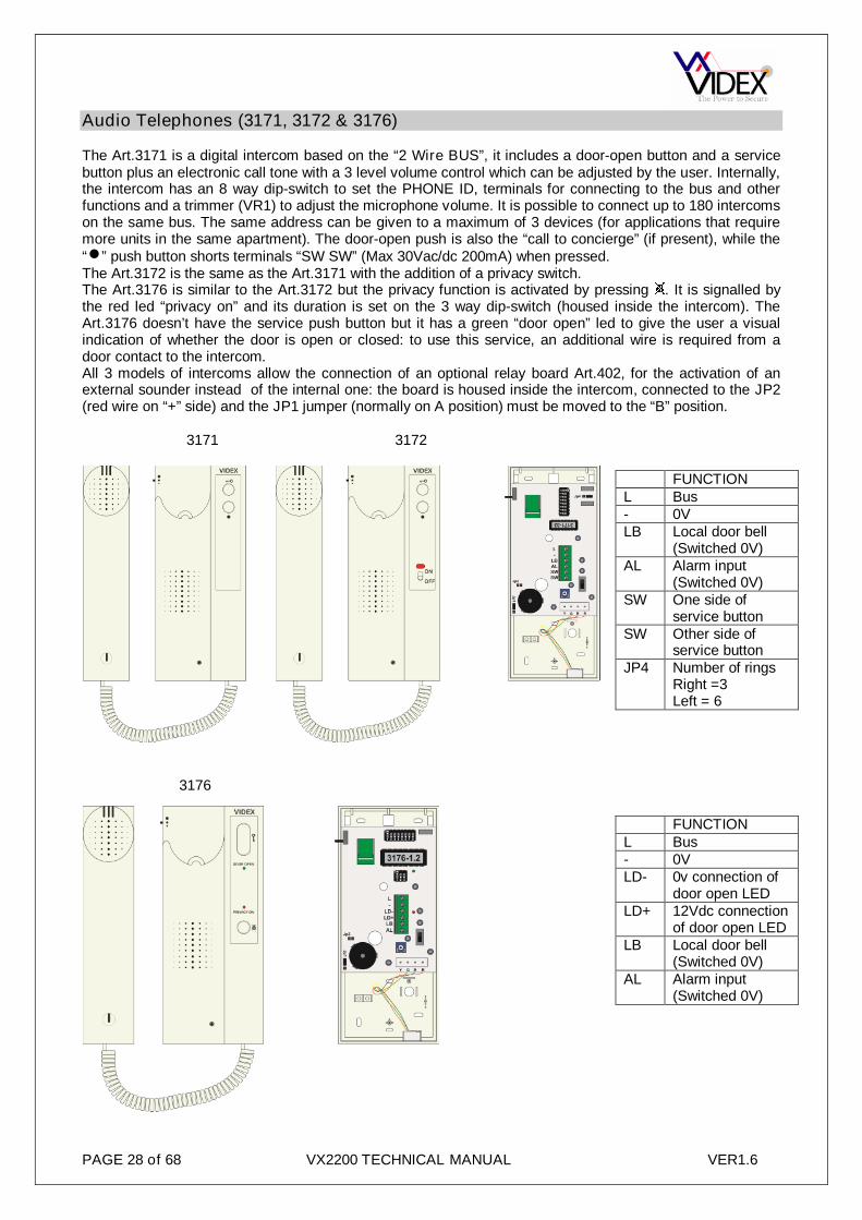
The Art.3171 is a digital intercom based on the “2 Wire BUS”, it includes a door-open button and a servicebutton plus an electronic call tone with a 3 level volume control which can be adjusted by the user. Internally,the intercom has an 8 way dip-switch to set the PHONE ID, terminals for connecting to the bus and otherfunctions and a trimmer (VR1) to adjust the microphone volume. It is possible to connect up to 180 intercomson the same bus. The same address can be given to a maximum of 3 devices (for applications that requiremore units in the same apartment). The door-open push is also the “call to concierge” (if present), while the“” push button shorts terminals “SW SW” (Max 30Vac/dc 200mA) when pressed.The Art.3172 is the same as the Art.3171 with the addition of a privacy switch.The Art.3176 is similar to the Art.3172 but the privacy function is activated by pressing . It is signalled bythe red led “privacy on” and its duration is set on the 3 way dip-switch (housed inside the intercom). TheArt.3176 doesn’t have the service push button but it has a green “door open” led to give the user a visualindication of whether the door is open or closed: to use this service, an additional wire is required from adoor contact to the intercom.All 3 models of intercoms allow the connection of an optional relay board Art.402, for the activation of anexternal sounder instead of the internal one: the board is housed inside the intercom, connected to the JP2(red wire on “+” side) and the JP1 jumper (normally on A position) must be moved to the “B” position.
3171 3172
3176
FUNCTIONL Bus- 0VLB Local door bell
(Switched 0V)AL Alarm input
(Switched 0V)SW One side of
service buttonSW Other side of
service buttonJP4 Number of rings
Right =3Left = 6
FUNCTIONL Bus- 0VLD- 0v connection of
door open LEDLD+ 12Vdc connection
of door open LEDLB Local door bell
(Switched 0V)AL Alarm input
(Switched 0V)

PAGE 29 of 68 VX2200 TECHNICAL MANUAL VER1.6
OPERATIONTo answer a call and open the door: Pick the handset up and speak with the visitor (or concierge); press the‘ ’ button (if it is an external call) to open the door (an acoustic signal will be emitted and the door will beopened for the time programmed) or replace the handset to end the conversation; if the call is local (localbell), the call tone will have a different tone.
To call the Concierge Unit (if available): With the handset replaced, press the “ ” button and wait: Aconfirmation tone will be heard, the call is booked on the concierge and will be answered at the discretion ofthe operator.
To activate the service relevant to the push button (except the Art.3176): It is possible to use this pushbutton as an “alarm” push button: make a short between one of the “SW” terminal and the “-” terminal andthen connect the free “SW” terminal to the “AL” terminal. The signal generated will be received by theconcierge and/or by the Art.512DR to activate an additional service.
PROGRAMMINGTo select the desired melody (3171 & 3172 only): Hold down “ ” button until (Approx. 10 seconds) theintercom plays the active melody; at the end of the melody the intercom will emit a beep (end of play);1. Listen to the available melodies (by pressing and releasing the “ ” button).2. After the ‘end of play’ beep if you don’t press the “ ” button within 3 seconds, the last melody heard is
selected.
To switch ON the privacy mode:For the Art.3172 put the switch into the ON position. The small window over the switch will be RED.For the Art.3176 press the push button marked ; the red LED “privacy on” will illuminate.
To switch OFF the privacy mode:For the Art.3172 put the switch into the OFF position. The small window over the switch will be WHITE.For the Art.3176 press the push button marked ; the red LED “privacy on” will switch off.
ID programming is carried out by setting the internal 8 way dip-switch to the positions shown on thedecimal/binary conversion table of this manual.The Art.3176 also has an additional 3 way dip-switch to set the duration of the privacy time as follows:
DIP SWITCH S1Time
DIP SWITCH S1Time
1 2 3 1 2 3off off off unlimited off off on 2 hourson off off 15min on off on 4 hoursoff on off 30min off on on 8 hourson on off 1hour on on on 16 hours
Technical SpecificationsAddressing range : from 1 to 180 (BIN code)Working voltage : BUS line VoltageStand-by absorption : about 0.6 mAPhone max. absorption : about 80mAWorking temperature : -10 +50 C°

PAGE 30 of 68 VX2200 TECHNICAL MANUAL VER1.6
AUDIO APARTMENT STATION (5178)
The 5178 is an audio apartment station availablein white, silver or carbon fibre ABS plastic and isa surface mount unit which connects to theVX2200 bus via a 4 wire bus. The apartmentstation has half duplex speech (Hands freespeech) and the facility to switch into simplexspeech mode by holding the talk/answer buttondown during a call. The apartment stationincludes the following buttons.
PUSH BUTTONS, LED’S AND CONTROLS
Service push button - When pressed, shorts terminal “S1” to terminal “GND” (ground).
Answer - On an incoming call, operation of this button allows the user to answer and converse with the visitor. The LED nextto the button will illuminate.Switch off - With the system switched on (Call in progress), momentary operation of the button will switch the apartmentstation off. The apartment station will also automatically switch off after a time delay if the button is not pressed. The LEDnext to the button will go off.Simplex button - Pressing and holding the button for more than 3 seconds will switch the apartment station into SIMPLEXspeech mode. Press and hold the button to speak to the caller (The LED next to the button will flash rapidly), release thebutton to listen (The LED will flash slowly). If the button is not pressed for 10 seconds the apartment station will switch off.The apartment station will revert to half duplex speech when another call is made.Privacy on-off - enable/disable the service. The LED next to the button will illuminate when the privacy service is enabled.
Concierge call– While in standby, press this button to call the concierge (If service is available).Door open - During a call, operation of this button will activate the “door open”Calltone volume controls – 3 levels available. Press the left key to decrease volume and the right to increase volume.Choose calling melody – 9 melodies available. See programming section for operation of these buttons.
Description Signal TerminalOne side of the service button SB 1Door open & AUX LED ground -LD 2+12V dc input to power the apartment station +12V 30V supply input and bus ground GND 4Bus line (Data/speech) L 5Local door bell input (Triggered by 0V) LB 6Alarm button input (Triggered by 0V) AL 7Other side of the service button SA 8AUX LED +12V input AUL 9Door open LED +12V input DOL 10
PROGRAMMINGProgramming is carried out by setting the internal 8 way dip-switch to the positions shown on thedecimal/binary conversion table of this manual.
PROGRAMMING THE MELODY
Press and hold the two melody buttons “ ” (for approx 10 seconds) until the unit plays the currentstored melody and emits a beep.
Press the melody button again (left or right) to listen to the available melodies (maximum 9). When the chosen melody has been reached, do not press any buttons, wait 3 seconds for the exit
beep. The new melody is now stored.

PAGE 31 of 68 VX2200 TECHNICAL MANUAL VER1.6
PROGRAMMING NUMBER OF RINGS (FACTORY SET 6 RINGS) Press and hold “ ” (for approx 10 seconds) until the unit emits a beep. Press “ ” as many times as the number of rings required (i.e. 6 presses = 6 rings with a maximum
of 9 rings) Once the number of rings required has been reached, wait 3 seconds for the exit beep. The new value is now stored.
PROGRAMMING THE PRIVACY DURATION (FACTORY SET WITH OUT TIMEOUT)
Press and hold “ ” (for approx 10 seconds) until the unit emits a beep.
Press “ ” again to set the privacy duration. Each time the button is pressed, it will increase theprivacy duration by 15 minutes (starting from 0 up to a maximum of 20 hours i.e. pressing the button8 times = 2 hours up to a maximum of 80 presses for 20 hours). Once the required privacy durationhas been reached, wait 3 seconds for the exit beep.To set the privacy with no time out Press and
hold “ ” (for approx 10 seconds) until the unit emits a beep do not press any other button, wait 3seconds for the exit beep.
The new value is now stored.
RESTORE FACTORY DEFAULTS Power up the intercom keeping pressed “ ”; The intercom will emit a beep to confirm the operation; Release “ ”.
TECHNICAL SPECIFICATIONAddressing range : from 1 to 180 (BIN code)Working voltage : 12VdcStand-by absorption : about 6mAPhone max. absorption : about 50mAWorking temperature : -10 +50 C°

PAGE 32 of 68 VX2200 TECHNICAL MANUAL VER1.6
VIDEOPHONES
3371(Mono) 3471(Colour) 3376(Mono) 3476(Colour) 3980 (Back plate)
The Art.3371 (3471 colour) is a digital videophone based on a “6 Wire BUS”, it includes 5 push buttons asshown in the table below and the images above. The call is an electronic tone with a 3 level volume controlwhich can be adjusted by the user. To connect the videophone to the “BUS”, use the PCB connectorprovided with the mounting plate Art.3980. The videophone has an 8 way dip-switch to set the PHONE ID, a5 way dip-switch to set the video system (coax or non coax) and a trimmer (VR1) to adjust the microphonevolume; all accessible from the rear of the videophone. It is possible to connect 180 videophones to thesame system and if necessary it is possible to give the same address to a maximum of 3 (for thoseapplications that require more units in the same apartment. It is also necessary to add additional videosplitters and PSU’s). The Art.3376 (3476 colour) have one less service button than the Art.3371 but has atimed privacy button, privacy LED and a door open LED.
PUSH BUTTONS, LED’S AND CONTROLSDoor open - During a call, operation of this button will activate the “door open”Concierge call– While in standby, press this button to call the concierge (If service is available).
Set to Camera recall – Press this to recall the door panel camera image. Press it the number of times as the door number torecall. For example, press 3 times to recall door 3.Set to alarm – Pressing this button will send an alarm signal to the concierge and or any 512DR’s address to 255.
SPARE SERVICE BUTTON
S1 SPARE SERVICE BUTTON
S2 SPARE SERVICE BUTTON
Privacy on-off - enable/disable the service. The PRIVACY ON LED will illuminate when the privacy service is enabled.
ON RED LED- Indicates the monitor is switched on during a call
PRIVACYON
RED LED- Privacy is enabled
DOOROPEN
GREEN LED- Indicates when the door has been released
Call tone volume control – 3 levels available.
Picture brightness
Picture contrast
OPERATIONTo answer a call and open the door: Pick up the handset and speak with the visitor (or concierge); press“ ” (if it is an external call) to open the door (an acoustic signal will be emitted and the door will open forthe time programmed) or replace the handset to end the conversation; if the call is local (local bell), the calltone will have a different tone.
To call the Concierge Unit: With the handset replaced, press “ ” and wait: a confirmation tone will beheard; the call is booked on the concierge and will be answered at the discretion of the operator;
To activate the privacy mode (Art.3376 only)
Press the push button labelled , the red “privacy on” LED will switch on. To disable the privacy modebefore the configured time expires, press the same push button again.

PAGE 33 of 68 VX2200 TECHNICAL MANUAL VER1.6
CONNECTIONS
Notes1
The voltage is available when the monitor is switched on and is normally only usedon coax video systems.2
Only for monitors with memory board Art.35xx.
Art.3376 – Description of the signals on the Art.3980 back plate
Set as non-coax Set as coax1 Not used2 P3 – Push button shorts to COM when pressed3 P4 – Push button S1 shorts to COM when pressed4 DOL - Door open LED signal (+12Vdc 5mA signal)5 +20 - +20Vdc monitor power supply6 +20 - +20Vdc monitor power supply7 V1 (balanced video signal sync-) Not used8 V2 (balanced video signal sync+) V – Coax centre core9 GNDV Ground reference for video signal Screen of coax10 +12 - 12Vdc output for coax video distributor Art.894 power supply
1
11 COM - Common terminal for P3 and P412 +MV - +12Vdc input for powering memory board
2
13 L (Bus Data line)
14 - (Bus date line GND)15 LB - Local bell input (Switch 0V input)16 AL - Alarm signal input (Switched 0V input)17 R- (17),R+ (18) - Connection terminal for the additional relay board18 Art.402 (black wire to terminal R-, red wire to terminal R+)
Art.3371 – Description of the signals on the Art.3980 back plate
Set as non-coax Set as coax1 Not used2 P3 – Push button shorts to COM when pressed3 P4 – Push button S1 shorts to COM when pressed4 P5 – Push button S2 shorts to COM when pressed5 +20 - +20Vdc monitor power supply6 +20 - +20Vdc monitor power supply7 V1 (balanced video signal sync-) Not used8 V2 (balanced video signal sync+) V – Coax centre core9 GNDV Ground reference for video signal Screen of coax10 +12 - 12Vdc output for coax video distributor Art.894 power supply
1
11 COM - Common terminal for P3, P4 and P512 +MV - +12Vdc input for powering memory board
2
13 L (Bus Data line)
14 - (Bus date line GND)15 LB - Local bell input (Switch 0V input)16 AL - Alarm signal input (Switched 0V input)17 R-,R+ - Connection terminal for the additional relay board Art.402 (black18 wire to terminal R-, red wire to terminal R+)

PAGE 34 of 68 VX2200 TECHNICAL MANUAL VER1.6
PROGRAMMINGThe programming of this videophone consists of the following stages:- Set the PHONE ID on the 8 way dip-switch shown on decimal/binary conversion table in this manual;- Set the video format, coax or balanced (non-coax). As shown in the table below:-
SWITCH 1 2 3 4 5Non-Coax (BalancedVideo
OFF ON ON ON ON
Coax (Composite video) ON OFF ON ON ON
- Setting of the number of rings; the default setting is 3, to set 6 rings follow these steps:a. switch off the videophone by unplugging the flat cable from the PCB connection;b. make a short between terminals 14 and 15 (signals “-” and “LB”) of the PCB connection;c. plug the flat cable onto the PCB connection and wait for a double beep before removing the short
between terminals 14 and 15;d. to revert to 3 rings, do the same but wait for only one beep before removing the short between
terminals 14 and 15.- Setting the “”button function; the default function setting for this push button is the camera recall, to set
the push button as an alarm call:a. Switch off the videophone by unplugging the flat cable from the PCB connection.b. While pressing the “” push button, plug the flat cable onto the PCB connection and wait for a double
beep before release the push button.c. To revert to the recall function, do the same but wait for only one beep before release the push button.
When you use the Art.402 for both Art.3371 and 3376, the fourth switch on the 5 way dip-switch should bemoved to OFF.The wires of the Art.402 must be connected; black to terminal 17 (R- signal), red to terminal 18 (R+ signal).For the Art.3376 it is necessary to set the duration of the privacy mode by setting the 3 way dip-switch(accessible from the rear side of the videophone) as shown on the table below.
3376 (3476) 3 WAY DIP-SWITCH FOR PRIVACY TIME
Dip-SwitchTime
1 2 3off off off unlimitedon off off 15minoff on off 30minon on off 1houroff off on 2 hourson off on 4 hoursoff on on 8 hourson on on 16 hours
TECHNICAL SPECIFICATIONAddressing range : from 1 to 180 (BIN code)Stand-by absorption : about 0.6mAVideophone max. absorption : about 400mA (20 Volt)Working temperature : -10 +50 C°
When connecting two or more videophonesin series without the use of video distributorsdip switches 3 & 5 should only be switchedon at the end of line.

PAGE 35 of 68 VX2200 TECHNICAL MANUAL VER1.6
Video monitor (5478, 5476)
An intelligent Hands-free (surface or flushmounting) video monitor employing a colour3.5” active matrix LCD display. The 5478 isavailable in white, silver and carbon fibrefinishes and can be fitted with the optional flushkit or handset kit.The 5478 includes push buttons for “door
open/concierge call”, “answer/camera recall”, “privacy on/off”, “Latchingrelay activation” and 2 service buttons plus 4 LED’s associated with the 4main buttons. In addition to the above, the unit has also controls forloudspeaker volume, call tone volume, brightness and hue withprogrammable number of rings, privacy duration and melody.
The buttons and LED’s have the following functions:-Service push button - When pressed, shorts terminal 12 “S1” to terminal “GND” (ground). (Max 24Vdc 50mA)Latching output – Each time this button is pressed it will toggle terminal 14 between ground and open collector. The LED nextto the button will illuminate when the output is groundedAnswer button - On an incoming call, operation of this button allows the user to answer and converse with the visitor. TheLED next to the button will illuminate.Camera recall button - Press as many times as the DEVICE N. of the door station to switch on.Switch off button - With the system switched on (monitor on), momentary operation of the button will switch the video monitoroff. The videomonitor will also automatically switch off after a time delay if the button is not pressed. LED 2 will switch off.Simplex button - Pressing and holding the button for more than 3 seconds will switch the videomonitor into SIMPLEX speechmode. Press and hold the button to speak to the caller (The LED will flash rapidly), release the button to listen (The LED willflash slowly). If the button is not pressed for 10 seconds the videomonitor will switch off. The videomonitor will revert toduplex speech when another call is made.When pressed, shorts terminal 13 “S2” to Terminal “GND” (ground). (Max 24Vdc 50mA)Privacy on-off button - Press to enable/disable the service. The LED next to the button will illuminate when the privacyservice is enabled.Concierge call button – While in standby, press this button to call the concierge (If service is available).Door open button - During a call, operation of this button will activate the door.Loudspeaker volume controlCall tone volume control
Brightness control
Colour intensity control
Terminal Signal Description
1 & 2 +20V Video power supply input 17-20Vdc
3 & 4 GND Video power ground connection
5 V2/V Balanced video V2 input or coax centre core (Set by 4 way dip-switches)
6 V1 Balanced video V1 input
7 L Data/speech bus input
8 GND Bus ground
9 LB Local door bell input (Switched to ground to trigger)
10 AL Alarm button input (Switch to ground to trigger)
11 GND Ground
12 S1 S1 push button (Shorts to Ground when pressed)
13 S2 S2 push button (Shorts to Ground when pressed)
14 push button (Latching toggle action)
15 +VD +12Vdc output to power video distribution unit (Art. 894)
16 GND Ground
17 12VO Regulated 12Vdc output
18 12VI +12Vdc power supply input

PAGE 36 of 68 VX2200 TECHNICAL MANUAL VER1.6
19 LD Auxiliary LED +12V input (LED next to door open button)
20 GND Ground
PROGRAMMINGSetup is carried out using the push buttons on the front of the unit and the dip-switches located on the rear ofthe unit. An eight way dip-switch bank is used to set the address of the apartment as shown in thedecimal/binary conversion chart in this manual. Additionally there is a 4 bank dip switch which is used toselect the video type (either coaxial or balanced video twisted pair).
4 WAY DIPSWITCH1 2 3 4 Video Mode
ON ON OFF ON Coaxial video (V2 = V, GND = Screen)ON ON ON OFF Balance video (V1 & V2)
Switches 1 and 2 adjust the video signal impedance. When using more than one video monitor in serieswithout a video splitter put both switches in the OFF position on all but the last video monitor (end of line).
Number of rings (Factory default = 6 rings)
Press and hold (for approx 10 seconds) “ ” until the LED next to the button illuminates and the unitemits a beep.
Press “ ” again as many times as the number of rings required (i.e. 6 times = 6 rings, maximum 9times).
Once the value of rings has been reached, wait 5 seconds for a beep and the LED turning OFF. The new value is stored.
Privacy duration time (Factory default = No time out)
Press and hold (for approx 10 seconds) “ ” until the LED next to the button illuminates and the unitbeeps.
Each time the “ ” button is pressed; it will increase (starting from 0) the privacy duration by 15minutes.
Press until the required duration has been reached, when reached, wait 5 seconds for a beep andthe LED turning OFF.
The new time will be stored.
To set the privacy with no time out (privacy enabled or disabled only by pressing the “ ” button),don't press any buttons once in privacy programming mode and wait 5 seconds for the beep andLED to go off.
Call tone melody (Factory default = melody 1) Press and hold “” (or “ “on the SL5478) for approx 10 seconds until the LED next to the button
illuminates and the unit plays the current programmed melody. Press again “” (or the “ “ on the SL5478) to listen to the available melodies (9 Available). Once
the chosen melody has been reached, wait 5 seconds for a beep and the LED turning OFF. The new melody will be stored

PAGE 37 of 68 VX2200 TECHNICAL MANUAL VER1.6
Video monitor (SL5478)
The SL5478 is a slimline version of the 5478. Thismodel is surface mount only and unlike the 5478does not require a separate mounting plate.Connections, programming, and functions are thesame as the 5478 with the exception of the “” button which is non-latching on the SL5478. The “ “button is also used instead of the “” button when programming the call tone melody. The 4 way dipswitch is also different to the 5478 as shown below.
4 WAY DIPSWITCH1 2 3 4 Video Mode
ON OFF ON ON Coaxial video (V2 = V, GND = Screen)OFF ON ON ON Balance video (V1 & V2)
TECHNICAL SPECIFICATIONAddressing range : from 1 to 180 (BIN code)Stand-by absorption : approx 12mA standby on 12V inputCall absorption : approx 70mA max on 12Vdc input (During a call)
: approx 250mA max on 20Vdc input (During a call)Working temperature : -10 +50 C°
Video monitor (VR5178, VR5478)
The VR5178 is a vandal resistant flush mount audio apartment station in 12 gauge stainless steel whichconnects to the VX2200 bus via a 4 wire bus. The apartment station has half duplex speech (Handsfreespeech) and the facility to switch into simplex speech mode by holding the talk/answer button down. TheVR5478 also included a 3.5” TFT OSD monitor.
PUSH BUTTONSAnswer button - On an incoming call, operation of this button allows the user to answer and converse with the visitor. TheLED next to the button will illuminate.Switch off button - With the system switched on (Call in progress), momentary operation of the button will switch theapartment station off. The apartment station will also automatically switch off after a time delay if the button is not pressed.The LED next to the button will go off.Simplex button - Pressing and holding the button for more than 3 seconds will switch the apartment station into SIMPLEXspeech mode. Press and hold the button to speak to the caller (The LED next to the button will flash rapidly), release thebutton to listen (The LED will flash slowly). If the button is not pressed for 10 seconds the apartment station will switch off.The apartment station will revert to duplex speech when another call is made.Privacy on-off button - Enable/disable the service. The LED next to the button will illuminate when the privacy service isenabled.During a call, this button acts as a menu button to enter programming mode.Concierge call button – While in standby, press this button to call the concierge (If service is available).Door open button - During a call, operation of this button will activate the door.

PAGE 38 of 68 VX2200 TECHNICAL MANUAL VER1.6
Description SignalNOT USED T+12V output to power 894 video splitter +VD+15-20dc input to power video monitor +20Balanced video signal 1 V1Balanced video signal 2 or coax centre core V2Video ground -+12V output (Max 100mA) +VoNOT USED 2NOT USED 4+12V input +VIBus 0V -Bus line L1Local door bell input (Active low) LBAlarm input (Active low) AL5
Service button output (Open collector) Triggered by holding for more than 3 seconds SB
Door monitoring LED input (+12Vdc to trigger) DL
PROGRAMMINGAddress programming is carried out by setting the internal 8 way dip-switch to the positions shown on thedecimal/binary conversion table of this manual.
The four way dip-switch sets the video signal type accepted by the monitor as shown in the table below:-4 WAY DIPSWITCH1 2 3 4 Video Mode
ON OFF ON ON Coaxial video (V2 = V, - = M)OFF ON ON ON Balance video (V1 & V2)
VR5178 PROGRAMMINGWhen in programming mode, after 3 seconds of idle time, the unit will return to normal operation storing theparameter related to the function that was in progress.
VR5178 – Setting the number of rings When the system is in stand-by, press and hold “ ” until the related LED starts flashing and the intercoms
emit a beep. Press “ ” as many times (each press is confirmed by a beep) as the number of rings (max 9) required. Once the number of rings required is reached (i.e. press 5 times for 5 rings), wait (approx 3 seconds) until
the LED switches off. The new number of rings is stored.
VR5178 – Setting the melody and melody volume When the system is in stand-by, press and hold (for approx 10 seconds) the “ ” button until the intercom
plays the current melody and the “talk” and “privacy” LED’s illuminate. At the end of the current melody theintercom emits a beep and the “talk” and “privacy” LED’s start to flash.
To adjust the volume of the melody, press (several times or hold) the “ ” button to decrease the volume orthe “ ” button to increase the volume (the volume of emitted beeps vary according to the button pressed).
Each time the “ ” button is pressed, a new melody (9 are available) is selected: the “talk” and “privacy”LED’s stop flashing during play, at the end a beep is emitted and the two LED’s restart to flash.
Repeat the step above to select a new melody otherwise wait approx 3 seconds (the LEDs switch OFF)without pressing any button to accept the melody played and set the volume as adjusted.
VR5178 - Privacy duration programming Press and hold “ ” (for approx 10 seconds) until the unit emits a beep and the related LED starts flashing. Each time “ ” is pressed, it will increase the privacy duration by 30 minutes (starting from 0 up to a
maximum of 20 hours i.e. pressing the button 6 times = 3 hours up to a maximum of 40 presses for 20hours). To set the privacy with no time out do not press the button.
Once the required privacy duration has been reached, wait 3 seconds for the exit beep. The new value is now stored.
VR5178 – Speech volume adjustments When a conversation is in progress (“speak” LED illuminated), press “ ”: the “privacy” LED starts flashing
and the “talk” LED turns OFF.

PAGE 39 of 68 VX2200 TECHNICAL MANUAL VER1.6
Press (several times or hold pressed) “ ” to increase the speech volume or the “ ” button to decreasethe volume.
Once the required volume level is reached, wait approx 3 seconds or press again the “ ” button. The “privacy” LED switches OFF while the “talk” LED switches back ON.
VR5478 PROGRAMMING MENU’SThe video monitor has two menus for programming and adjustment functions:1. The 1
stmenu can be entered when the system is in stand-by and allows the following settings:
Privacy duration, melody volume, melody, number of rings. (Note: 20Vdc must be on for this function)2. The 2
ndmenu is available when the system is turned ON (during a conversation or a camera recall)
Speech volume, brightness, contrast, hue
Menu 1 When the system is in stand-by (monitor turned OFF) press and hold (for approx 9 seconds) “ ” to enter
the programming menu; The menu appears on the display: the top of the screen shows “menu” followed by the available function
icons, the bottom of the screen shows the currently selected function value on the left, the currentlyselected function icon in the middle and the next function icon on the right.
The first function is the privacy duration time (max 20 hours): press (several times or hold) “ ” to increaseor “ ”to decrease the duration in multiples of 30 minutes for each press (signalled by a beep).
Press “ ”to store the new value and to move onto the next programming option. Next is the melody volume: press (several times or hold) “ ”to increase or “ ” to decrease the melody
volume (signalled by a beep). Press “ ”to store the new value and to move onto the next programming option. Next is the melody type: press “ ”to hear and select the previous melody or “ ”to hear and select the
following melody (9 available). Press “ ” to store the new value and to move onto the next programming option. Next and final is the number of rings (max 9): (press several times or hold) “ ” to increase or “ ” to
decrease the number of rings. Press “ ”to store the new value and exit the programming menu, the monitor turns OFF.
Menu 2 When the system is turned ON (conversation or camera recall) press “ ” to enter the programming menu. The menu appears on the display: the top of the screen shows “menu” followed by the allowed function
icons, the bottom of the screen shows the currently selected function value on the left, the currentlyselected function icon in the middle and the next function icon on the right.
The first function is the speech volume: press (Several times or hold) “ ” to increase or “ ” to decreasethe speech volume level (signalled by a beep).
Press “ ” to store the new value and to move onto the next programming option. Next is the picture brightness: press (Several times or hold) “ ” to increase or “ ” to decrease the
brightness level (signalled by a beep). Press “ ” to store the new value and to move onto the next programming option. Next is the picture contrast: press (Several times or hold) “ ” to increase or “ ” to decrease the contrast
level (signalled by a beep). Press “ ” to store the new value and to move onto the next programming option. The next and last function is the picture hue: press (Several times or hold) “ ” to increase or “ ” to
decrease the hue level (signalled by a beep). Press “ ” to store the new value and exit the programming menu the monitor goes back to shown standard
messages for call progress.
Technical Specifications Audio VideoAddressing range : from 1 to 180 (BIN code) : from 1 to 180 (BIN code)Working voltage : 12VdcStand-by absorption : about 6mA : approx 12mA on 12V, 6mA on 20V inputsPhone max. absorption : about 50mA : approx 70mA max on 12Vdc input
: approx 250mA max on 20Vdc inputWorking temperature : -10 +50 C° : -10 +50 C°

PAGE 40 of 68 VX2200 TECHNICAL MANUAL VER1.6
Video monitor (3678)
The 3678 is a wall mount colourvideophone with 3.5” TFT OSD monitor.Both handset and handsfree (Half duplex)speech are available along with the facilityto switch into simplex speech mode byholding the talk/answer button down formore than 3 seconds. Additional features
include timed privacy, an auxillary outout and LED’s to indicate callanswer, privacy active and door release. An Art.5980 mountingplate is required for this monitor.
PUSH BUTTONSAnswer button - On an incoming call, operation of this button allows the user to answer and converse with the visitor withoutlifting the handset. The LED next to the button will illuminate.Switch off button - With the system switched on (Call in progress), momentary operation of the button will end the call(Alternatively, replacing the handset will also end the call). The apartment station will also automatically switch off after a timedelay if the button is not pressed. The LED next to the button will switch off.Simplex button - Pressing and holding the button for more than 3 seconds will switch the apartment station into SIMPLEXspeech mode. Press and hold the button to speak to the caller (The LED next to the button will flash rapidly), release thebutton to listen (The LED will flash slowly). If the button is not pressed for 10 seconds the apartment station will switch off.The apartment station will revert to duplex speech when another call is made.Privacy on-off button - Enable/disable the service. The LED next to the button will illuminate when the privacy service isenabled. Pressing this button while the unit is ringing will reject a call.During a call, this button acts as a menu button to enter programming mode if pressed momentarily or if pressing until a beepis omitted, activates the auxiliary output (SB)Concierge call button – While in standby, press this button to call the concierge (If service is available).Door open button - During a call, operation of this button will activate the door.
Terminal Signal Description
1 & 2 +20V Video power supply input 17-20Vdc
3 & 4 GND Video power ground connection
5 V2/V Balanced video V2 input or coax centre core (Set by 4 way dip-switches)
6 V1 Balanced video V1 input
7 L Data/speech bus input
8 GND Bus ground
9 LB Local door bell input (Switched to ground to trigger)
10 AL Alarm button input (Switch to ground to trigger)
11 Not Used
12 SB S1 push button (Shorts to Ground when pressed)
13 & 14 Not Used
15 +VD +12Vdc output to power video distribution unit (Art. 894)
16 GND Ground
17 12VO Regulated 12Vdc output
18 12VI +12Vdc power supply input
19 LD Auxiliary LED +12V input (LED next to door open button)
20 GND Ground
PROGRAMMINGAddress programming is carried out by setting the internal 8 way dip-switch to the positions shown on thedecimal/binary conversion table of this manual.
The four way dip-switch sets the video signal type accepted by the monitor as shown in the table below:-4 WAY DIPSWITCH1 2 3 4 Video Mode
ON OFF ON ON Coaxial video (V2 = V, - = M)OFF ON ON ON Balance video (V1 & V2)
Note: Switches 3 & 4 are video end of line termination (Both on for end of line termination or both off for no end of line termination
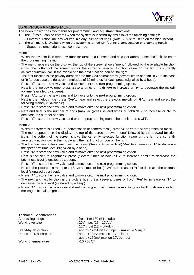
PAGE 41 of 68 VX2200 TECHNICAL MANUAL VER1.6
3678 PROGRAMMING MENUThe video monitor has two menus for programming and adjustment functions:1. The 1
stmenu can be entered when the system is in stand-by and allows the following settings:
Privacy duration, melody volume, melody, number of rings. (Note: 20Vdc must be on for this function)2. The 2
ndmenu is available when the system is turned ON (during a conversation or a camera recall)
Speech volume, brightness, contrast, hue
Menu 1 When the system is in stand-by (monitor turned OFF) press and hold (for approx 9 seconds) “ ” to enter
the programming menu; The menu appears on the display: the top of the screen shows “menu” followed by the available function
icons, the bottom of the screen shows the currently selected function value on the left, the currentlyselected function icon in the middle and the next function icon on the right.
The first function is the privacy duration time (max 20 hours): press (several times or hold) “ ” to increaseor “ ”to decrease the duration in multiples of 30 minutes for each press (signalled by a beep).
Press “ ”to store the new value and to move onto the next programming option. Next is the melody volume: press (several times or hold) “ ”to increase or “ ” to decrease the melody
volume (signalled by a beep). Press “ ”to store the new value and to move onto the next programming option. Next is the melody type: press “ ”to hear and select the previous melody or “ ”to hear and select the
following melody (9 available). Press “ ” to store the new value and to move onto the next programming option. Next and final is the number of rings (max 9): (press several times or hold) “ ” to increase or “ ” to
decrease the number of rings. Press “ ”to store the new value and exit the programming menu, the monitor turns OFF.
Menu 2 When the system is turned ON (conversation or camera recall) press “ ” to enter the programming menu. The menu appears on the display: the top of the screen shows “menu” followed by the allowed function
icons, the bottom of the screen shows the currently selected function value on the left, the currentlyselected function icon in the middle and the next function icon on the right.
The first function is the speech volume: press (Several times or hold) “ ” to increase or “ ” to decreasethe speech volume level (signalled by a beep).
Press “ ” to store the new value and to move onto the next programming option. Next is the picture brightness: press (Several times or hold) “ ” to increase or “ ” to decrease the
brightness level (signalled by a beep). Press “ ” to store the new value and to move onto the next programming option. Next is the picture contrast: press (Several times or hold) “ ” to increase or “ ” to decrease the contrast
level (signalled by a beep). Press “ ” to store the new value and to move onto the next programming option. The next and last function is the picture hue: press (Several times or hold) “ ” to increase or “ ” to
decrease the hue level (signalled by a beep). Press “ ” to store the new value and exit the programming menu the monitor goes back to shown standard
messages for call progress.
Technical SpecificationsAddressing range : from 1 to 180 (BIN code)Working voltage : 20V input (17 – 20Vdc)
: 12C input (12 – 14Vdc)Stand-by absorption : approx 12mA on 12V input, 6mA on 20V inputPhone max. absorption : approx 70mA max on 12Vdc input
: approx 250mA max on 20Vdc inputWorking temperature : -10 +50 C°

PAGE 42 of 68 VX2200 TECHNICAL MANUAL VER1.6
EXTENSION SOUNDER (512D) EXTENSION RELAY (512DR)
Compatible with the “2 wire” BUS and has an 8 way Dip-switch to program the address of the device. Up to3 units can be addressed with the same number (Ex.: 1 intercom and 2 extension sounders to be operatedwith the same apartment number). The call tone is different according to the origin of the call (Main entrancecall or local door bell). A two level volume control is available using jumper JP1 (only for 512D, while for512DR the JP1 is not used and stays in position “H”). Through the jumper JP2 it is possible to set thenumber of rings (512D) or the number of relay pulses (512DR) between 1 or 6. The current consumption onthe BUS line is less than 1mA in stand-by mode. The Art.512DR can also be used as a “service relay” for theentire BUS, activated by the alarm signal from an apartment. To use this function it is necessary to give theunit the address 255.
- The 512D unit will ring according to the programming (1 or 6 times), or until the intercom handset ispicked up.
- The 512DR unit will operate the relay for 1 or 6 x 2 seconds on, 2 seconds off ,according to theprogramming, or until the intercom handset is picked up.
Local call:- The 512D unit will ring the number of times the local bell is pressed.- The 512DR unit will activate the relay each time the local bell is pressed and will remain active as long
as the local bell remains pressed.
Alarm (only for 512DR addressed as 255)The unit 512DR will activate the relay for 1 second (Independent of JP2 jumper settings).
ProgrammingThe address of the unit must be programmed by means of the internal 8 way Dip-switch (see conversiontable decimal/binary) and must be the same as the phone or videophone connected in the apartment. To useas a service relay activated by the alarm signals sent on the bus, set the address to 255.
The jumper JP1 is used to set the volume of the call tone: position “H” = high, position “L” = low (only for512D, in the 512DR unit the JP1 must stay in position “H”).The jumper JP2 enables the configuration of the number of rings or relay pulses: position “A” = 1ring/pulse, position “B” = 6 rings/pulses.
In order to synchronize the local apartment call with the telephone, connect the “LB” terminal with the “LB”phone terminal.
Technical specificationsAddressing range : from 1 to 180Stand-by absorption : less than about 0.9mACall absorption : Approx. 15mARelay contacts : (Art.512DR)1A 125Vac maxWorking temperature : -10 +50 C°
512D 512DR
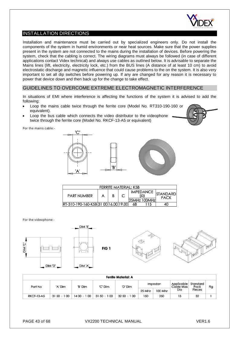
PAGE 43 of 68 VX2200 TECHNICAL MANUAL VER1.6
INSTALLATION DIRECTIONS
Installation and maintenance must be carried out by specialized engineers only. Do not install thecomponents of the system in humid environments or near heat sources. Make sure that the power suppliespresent in the system are not connected to the mains during the installation of devices. Before powering thesystem, check that the cabling is correct. The wiring diagrams must always be followed (in case of differentapplications contact Videx technical) and always use cables as outlined below. It is advisable to separate theMains lines (lift, electricity, electricity lock, etc.) from the BUS lines (A distance of at least 10 cm) to avoidelectrostatic discharge and magnetic influence that could cause problems to the on the system. It is also veryimportant to set all dip switches before powering up. If any are changed for any reason it is necessary topower that device down and then back up for the change to take effect.
GUIDELINES TO OVERCOME EXTREME ELECTROMAGNETIC INTERFERENCE
In situations of EMI where interference is affecting the functions of the system it is advised to add thefollowing: Loop the mains cable twice through the ferrite core (Model No. RT310-190-160 or
equivalent). Loop the bus cable which connects the video distributor to the videophone
twice through the ferrite core (Model No. RKCF-13-A5 or equivalent)
For the mains cable:-
For the videophone:-

PAGE 44 of 68 VX2200 TECHNICAL MANUAL VER1.6
CABLE GUIDE
The following table outlines the maximum resistance allowed from furthest point to furthest point.
Cable sizesDistance
up to(-) (L) (V1)* (V2)*
SignalsMax. Resistence
(-)* (+20)*Signals
Max. Resistence
100m 0.3mmsq AWG22
7.5 Ohms
0.6mmsq AWG195 Ohms200m 0.6mmsq AWG19 1.0mmsq AWG17
350m 1.0mmsq AWG17 1.5mmsq AWG15500m 1.5mmsq AWG15
Supply cables ( power supply outdoor station): they must have a minimum size of 1.0mmsq (AWG17)or more (Depending on the distance between the supply’s and the outdoor station) with maximum resistanceof 1.5 Ohm per core.
Door panel earth: All vandal resistant door panels must be earthed (Earth studs will be found on all vandalresistant panels and back boxes). To accomadate this we suggest running a 2.5mm
2earth cable from the
panel to the control cabinet where it can be connected to the cabinets earth.
Art.3161 Art.3162 Art.3171 Art.3172MIN. CORES <50m <100m <200m <300m <400m <500m
2 4 Pair CW1308CAT5
4 Pair CW13084 Core 0.5mm
2
YYCAT5
6 Pair CW13084 Core 0.75mm
2
YY
6 Pair CW13084 Core 1.0mm
2
YY
4 Core1.5mm
2YY
4 Core2.5mm
2YY
Art.31763 4 Pair CW1308
CAT56 Pair CW130812 Core 0.5mm
2
YY
6 Pair CW130812 Core 0.5mm
2
YY
10 Pair CW130812 Core 0.5mm
2
YY
7 Core1.5mm
2YY
7 Core2.5mm
2YY
Art.5178 Art.VR51784 4 Pair CW1308
CAT54 Pair CW130812 Core 0.5mm
2
YY
6 Pair CW130812 Core 0.5mm
2
YY
10 Pair CW130812 Core 0.5mm
2
YY
12 Core1.0mm
2YY
Notrecommended
Art.3371 Art.3471MIN. CORES <50m <100m <200m <300m <400m <500m
Balanced = 6 4 Pair CW1308CAT5
6 Pair CW1308or12 Core 0.5mm
2
YY
10 Pair CW1308or12 Core 0.5mm
2
YY
12 Core 0.5mm2
YYNotrecommended
Notrecommended
Coax = 4 + Coax 4 Pair CW1308 orCAT5+ RG59 (BC)
6 Pair CW1308or12 Core 0.5mm
2
YY+ RG59 (BC)
6 Pair CW1308or12 Core 0.5mm
2
YY+ RG59 (BC)
12 Core 0.5mm2
YY+ RG11 (BC)
12 Core0.75mm
2YY
+ RG11 (BC)
12 Core1.0mm
2YY
+ RG11 (BC)
Art.3376 Art.3476Balanced = 7 4 Pair CW1308 6 Pair CW1308
or12 Core 0.5mm
2
YY
10 Pair CW1308or12 Core 0.5mm
2
YY
12 Core 0.5mm2
YYNotrecommended
Notrecommended
Coax = 5 + Coax 4 Pair CW1308+ RG59 (BC)
6 Pair CW1308or12 Core 0.5mm
2
YY+ RG59 (BC)
6 Pair CW1308or12 Core 0.5mm
2
YY+ RG59 (BC)
12 Core 0.5mm2
YY+ RG11 (BC)
12 Core0.75mm
2YY
+ RG11 (BC)
12Core1.0mm
2
YY+ RG11 (BC)
Art.5476 Art.5478 Art.SL5478 Art.VR5478 Art.3678Balanced = 8 6 Pair CW1308 10 Pair CW1308
or12 Core 0.5mm
2
YY
12 Core 0.5mm2
YYNotrecommended
Notrecommended
Notrecommended
Coax = 7 + Coax 6 Pair CW1308+ RG59 (BC)
10 Pair CW1308or12 Core 0.5mm
2
YY+ RG59 (BC)
12 Core 0.5mm2
YY+ RG59 (BC)
12 Core0.75mm
2YY
+ RG11 (BC)
12 Core1.0mm
2YY
+ RG11 (BC)
12 Core1.5mm
2YY
+ RG11 (BC)

PAGE 45 of 68 VX2200 TECHNICAL MANUAL VER1.6
CAT5 NOTES: Only recommended for systems with up to 20 apartments and maximum distances of 70m formono video or 100m for colour video. Calculations based on a DC loop resistance <0.188 Ohm/m (Convertsto 94 Ohm/km). The following cores should be used on video systems. It is recommended to double up as aminimum (More cores may be required) the cores on audio systems as well:-
Orange & Orange/White pair = +20Green = V1Green/White = V2
Blue & Blue/White pair = LBrown & Brown/White pair = 0V
Note: Link the bus ground and the videoground terminals at the videophone.
CW1308 NOTES: CW1308 should have a maximum resistance of 97.8Ω/km. Calculate how many cores are required for each connection ensuring the maximum overall resistance on the L, - does not exceed 7.5 Ω, V1 & V2 does not exceed 15Ω and the power connections (+12, +20 & Video ground) does not exceed 5Ω. All other connections can have a maximum resistance of 10Ω
COAX NOTES: All videophones and video monitors can be supplied with coax video or balanced video (Dipswitches must be set correctly). The following cables are recommended:
RG59(BC) for internal use and distances of up to 200m (BC stands for bare copper. Copper coatedsteel CCS versions should not be used)RG11 for internal use and distances up to 600m.CT100 for external protected use and distances up to 200m.CT125 for external protected use and distances up to 600m.
YY NOTES: It is not recommended to use YY cable larger than 0.5mm2
for the balanced video connectionsV1 & V2 or to try doubling up on these connections as this will increase the capacitance of the cable andcould deteriorate the picture quality.
All the above cables are for internal wiring only unless otherwise stated.
SYSTEM NOTESBefore switch on the system, check the cabling and set all dip-switchesRemember to terminate the video end of line.All phones, videophones and accessories are identified by an address programmed through the 8 way Dip-
switch and each device must have a different address; see decimal/binary conversion table to program theaddresses. Note that each peripheral (phone, videophone or accessory) reads its address from thedip-switch at power up (when the system is powered): to change the address of a peripheral, it isnecessary that the peripheral is disconnected from the system (disconnect the BUS wires for thedevice, and then reconnect.
In case someone needs to activate more than one device by a single call (for example 2 intercoms in thesame apartment or 1 intercom and 1 additional sounder or 2 videophones, etc.), all devices must have thesame address (up to 3 devices max.). If the 3 units are videophones, to switch on at the same time anotherpower supply must be added, because the power supply Art.893N1 can supply a maximum 2 videophonesat the same time.
It is necessary to check that master and slave programming of call panels are correct.

PAGE 46 of 68 VX2200 TECHNICAL MANUAL VER1.6
SPEECH ADJUSTMENTIt is necessary to adjust the speech volume to have the best performance without “Larsen” effect(Feedback). It is advisable to carry out the following procedure:1. Be sure that microphone volume and speaker volume trimmers are in the middle position ( access holes
to the trimmers at the back of the panels);2. Make a call from the panel to the nearest phone on the BUS (the handset must be picked up) and speak
near the microphone of the outdoor station adjusting the balance trimmer in order to have the lowestfeedback from the speaker of the outdoor station;
3. Make another call towards the farthest phone in the BUS line (the handset must be picked up), thencheck the speech again at the nearest phone;
To adjust the handset microphone level, turn left or right the VR1 trimmer (inside the unit).
DIP-SWITCH SETTINGS
The following tables can be used when setting dip-switches on telephones, videophones and video monitors.Please note: All dip-switches must be set before power up.
Dip-sw 2 =offDip-sw 3 =off
DIP-SWITCH settingDip-sw 2 =onDip-sw 3 =off
DIP-SWITCH setting
Dec.Nr.
Art.2203Input Matrix
1 2 3 4 5 6 7 8Dec.Nr.
Art.2203Input Matrix
1 2 3 4 5 6 7 8
1 1a ON OFF OFF OFF OFF OFF OFF OFF 65 1a ON OFF OFF OFF OFF OFF ON OFF
2 1b OFF ON OFF OFF OFF OFF OFF OFF 66 1b OFF ON OFF OFF OFF OFF ON OFF
3 1c ON ON OFF OFF OFF OFF OFF OFF 67 1c ON ON OFF OFF OFF OFF ON OFF
4 1d OFF OFF ON OFF OFF OFF OFF OFF 68 1d OFF OFF ON OFF OFF OFF ON OFF
5 1e ON OFF ON OFF OFF OFF OFF OFF 69 1e ON OFF ON OFF OFF OFF ON OFF
6 1f OFF ON ON OFF OFF OFF OFF OFF 70 1f OFF ON ON OFF OFF OFF ON OFF
7 1g ON ON ON OFF OFF OFF OFF OFF 71 1g ON ON ON OFF OFF OFF ON OFF
8 1h OFF OFF OFF ON OFF OFF OFF OFF 72 1h OFF OFF OFF ON OFF OFF ON OFF
9 2a ON OFF OFF ON OFF OFF OFF OFF 73 2a ON OFF OFF ON OFF OFF ON OFF
10 2b OFF ON OFF ON OFF OFF OFF OFF 74 2b OFF ON OFF ON OFF OFF ON OFF
11 2c ON ON OFF ON OFF OFF OFF OFF 75 2c ON ON OFF ON OFF OFF ON OFF
12 2d OFF OFF ON ON OFF OFF OFF OFF 76 2d OFF OFF ON ON OFF OFF ON OFF
13 2e ON OFF ON ON OFF OFF OFF OFF 77 2e ON OFF ON ON OFF OFF ON OFF
14 2f OFF ON ON ON OFF OFF OFF OFF 78 2f OFF ON ON ON OFF OFF ON OFF
15 2g ON ON ON ON OFF OFF OFF OFF 79 2g ON ON ON ON OFF OFF ON OFF
16 2h OFF OFF OFF OFF ON OFF OFF OFF 80 2h OFF OFF OFF OFF ON OFF ON OFF
17 3a ON OFF OFF OFF ON OFF OFF OFF 81 3a ON OFF OFF OFF ON OFF ON OFF
18 3b OFF ON OFF OFF ON OFF OFF OFF 82 3b OFF ON OFF OFF ON OFF ON OFF
19 3c ON ON OFF OFF ON OFF OFF OFF 83 3c ON ON OFF OFF ON OFF ON OFF
20 3d OFF OFF ON OFF ON OFF OFF OFF 84 3d OFF OFF ON OFF ON OFF ON OFF
21 3e ON OFF ON OFF ON OFF OFF OFF 85 3e ON OFF ON OFF ON OFF ON OFF
22 3f OFF ON ON OFF ON OFF OFF OFF 86 3f OFF ON ON OFF ON OFF ON OFF
23 3g ON ON ON OFF ON OFF OFF OFF 87 3g ON ON ON OFF ON OFF ON OFF
24 3h OFF OFF OFF ON ON OFF OFF OFF 88 3h OFF OFF OFF ON ON OFF ON OFF
25 4a ON OFF OFF ON ON OFF OFF OFF 89 4a ON OFF OFF ON ON OFF ON OFF
26 4b OFF ON OFF ON ON OFF OFF OFF 90 4b OFF ON OFF ON ON OFF ON OFF
27 4c ON ON OFF ON ON OFF OFF OFF 91 4c ON ON OFF ON ON OFF ON OFF

PAGE 47 of 68 VX2200 TECHNICAL MANUAL VER1.6
Dip-sw 2 =offDip-sw 3 =off
DIP-SWITCH settingDip-sw 2 =onDip-sw 3 =off
DIP-SWITCH setting
Dec.Nr.
Art.2203Input Matrix
1 2 3 4 5 6 7 8Dec.Nr.
Art.2203Input Matrix
1 2 3 4 5 6 7 8
28 4d OFF OFF ON ON ON OFF OFF OFF 92 4d OFF OFF ON ON ON OFF ON OFF
29 4e ON OFF ON ON ON OFF OFF OFF 93 4e ON OFF ON ON ON OFF ON OFF
30 4f OFF ON ON ON ON OFF OFF OFF 94 4f OFF ON ON ON ON OFF ON OFF
31 4g ON ON ON ON ON OFF OFF OFF 95 4g ON ON ON ON ON OFF ON OFF
32 4h OFF OFF OFF OFF OFF ON OFF OFF 96 4h OFF OFF OFF OFF OFF ON ON OFF
33 5a ON OFF OFF OFF OFF ON OFF OFF 97 5a ON OFF OFF OFF OFF ON ON OFF
34 5b OFF ON OFF OFF OFF ON OFF OFF 98 5b OFF ON OFF OFF OFF ON ON OFF
35 5c ON ON OFF OFF OFF ON OFF OFF 99 5c ON ON OFF OFF OFF ON ON OFF
36 5d OFF OFF ON OFF OFF ON OFF OFF 100 5d OFF OFF ON OFF OFF ON ON OFF
37 5e ON OFF ON OFF OFF ON OFF OFF 101 5e ON OFF ON OFF OFF ON ON OFF
38 5f OFF ON ON OFF OFF ON OFF OFF 102 5f OFF ON ON OFF OFF ON ON OFF
39 5g ON ON ON OFF OFF ON OFF OFF 103 5g ON ON ON OFF OFF ON ON OFF
40 5h OFF OFF OFF ON OFF ON OFF OFF 104 5h OFF OFF OFF ON OFF ON ON OFF
41 6a ON OFF OFF ON OFF ON OFF OFF 105 6a ON OFF OFF ON OFF ON ON OFF
42 6b OFF ON OFF ON OFF ON OFF OFF 106 6b OFF ON OFF ON OFF ON ON OFF
43 6c ON ON OFF ON OFF ON OFF OFF 107 6c ON ON OFF ON OFF ON ON OFF
44 6d OFF OFF ON ON OFF ON OFF OFF 108 6d OFF OFF ON ON OFF ON ON OFF
45 6e ON OFF ON ON OFF ON OFF OFF 109 6e ON OFF ON ON OFF ON ON OFF
46 6f OFF ON ON ON OFF ON OFF OFF 110 6f OFF ON ON ON OFF ON ON OFF
47 6g ON ON ON ON OFF ON OFF OFF 111 6g ON ON ON ON OFF ON ON OFF
48 6h OFF OFF OFF OFF ON ON OFF OFF 112 6h OFF OFF OFF OFF ON ON ON OFF
49 7a ON OFF OFF OFF ON ON OFF OFF 113 7a ON OFF OFF OFF ON ON ON OFF
50 7b OFF ON OFF OFF ON ON OFF OFF 114 7b OFF ON OFF OFF ON ON ON OFF
51 7c ON ON OFF OFF ON ON OFF OFF 115 7c ON ON OFF OFF ON ON ON OFF
52 7d OFF OFF ON OFF ON ON OFF OFF 116 7d OFF OFF ON OFF ON ON ON OFF
53 7e ON OFF ON OFF ON ON OFF OFF 117 7e ON OFF ON OFF ON ON ON OFF
54 7f OFF ON ON OFF ON ON OFF OFF 118 7f OFF ON ON OFF ON ON ON OFF
55 7g ON ON ON OFF ON ON OFF OFF 119 7g ON ON ON OFF ON ON ON OFF
56 7h OFF OFF OFF ON ON ON OFF OFF 120 7h OFF OFF OFF ON ON ON ON OFF
57 8a ON OFF OFF ON ON ON OFF OFF 121 8a ON OFF OFF ON ON ON ON OFF
58 8b OFF ON OFF ON ON ON OFF OFF 122 8b OFF ON OFF ON ON ON ON OFF
59 8c ON ON OFF ON ON ON OFF OFF 123 8c ON ON OFF ON ON ON ON OFF
60 8d OFF OFF ON ON ON ON OFF OFF 124 8d OFF OFF ON ON ON ON ON OFF
61 8e ON OFF ON ON ON ON OFF OFF 125 8e ON OFF ON ON ON ON ON OFF
62 8f OFF ON ON ON ON ON OFF OFF 126 8f OFF ON ON ON ON ON ON OFF
63 8g ON ON ON ON ON ON OFF OFF 127 8g ON ON ON ON ON ON ON OFF
64 8h OFF OFF OFF OFF OFF OFF ON OFF 128 1a OFF OFF OFF OFF OFF OFF OFF ON

PAGE 48 of 68 VX2200 TECHNICAL MANUAL VER1.6
Dip-sw 2 =offDip-sw 3 =on
DIP-SWITCH settingDip-sw 2 =offDip-sw 3 =on
DIP-SWITCH setting
Dec.Nr.
Art.2203-1Input Matrix
1 2 3 4 5 6 7 8Dec.Nr.
Art.2203-1Input Matrix
1 2 3 4 5 6 7 8
129 1b ON OFF OFF OFF OFF OFF OFF ON 155 4d ON ON OFF ON ON OFF OFF ON
130 1c OFF ON OFF OFF OFF OFF OFF ON 156 4e OFF OFF ON ON ON OFF OFF ON
131 1d ON ON OFF OFF OFF OFF OFF ON 157 4f ON OFF ON ON ON OFF OFF ON
132 1e OFF OFF ON OFF OFF OFF OFF ON 158 4g OFF ON ON ON ON OFF OFF ON
133 1f ON OFF ON OFF OFF OFF OFF ON 159 4h ON ON ON ON ON OFF OFF ON
134 1g OFF ON ON OFF OFF OFF OFF ON 160 5a OFF OFF OFF OFF OFF ON OFF ON
135 1h ON ON ON OFF OFF OFF OFF ON 161 5b ON OFF OFF OFF OFF ON OFF ON
136 2a OFF OFF OFF ON OFF OFF OFF ON 162 5c OFF ON OFF OFF OFF ON OFF ON
137 2b ON OFF OFF ON OFF OFF OFF ON 163 5d ON ON OFF OFF OFF ON OFF ON
138 2c OFF ON OFF ON OFF OFF OFF ON 164 5e OFF OFF ON OFF OFF ON OFF ON
139 2d ON ON OFF ON OFF OFF OFF ON 165 5f ON OFF ON OFF OFF ON OFF ON
140 2e OFF OFF ON ON OFF OFF OFF ON 166 5g OFF ON ON OFF OFF ON OFF ON
141 2f ON OFF ON ON OFF OFF OFF ON 167 5h ON ON ON OFF OFF ON OFF ON
142 2g OFF ON ON ON OFF OFF OFF ON 168 6a OFF OFF OFF ON OFF ON OFF ON
143 2h ON ON ON ON OFF OFF OFF ON 169 6b ON OFF OFF ON OFF ON OFF ON
144 3a OFF OFF OFF OFF ON OFF OFF ON 170 6c OFF ON OFF ON OFF ON OFF ON
145 3b ON OFF OFF OFF ON OFF OFF ON 171 6d ON ON OFF ON OFF ON OFF ON
146 3c OFF ON OFF OFF ON OFF OFF ON 172 6e OFF OFF ON ON OFF ON OFF ON
147 3d ON ON OFF OFF ON OFF OFF ON 173 6f ON OFF ON ON OFF ON OFF ON
148 3e OFF OFF ON OFF ON OFF OFF ON 174 6g OFF ON ON ON OFF ON OFF ON
149 3f ON OFF ON OFF ON OFF OFF ON 175 6h ON ON ON ON OFF ON OFF ON
150 3g OFF ON ON OFF ON OFF OFF ON 176 7a OFF OFF OFF OFF ON ON OFF ON
151 3h ON ON ON OFF ON OFF OFF ON 177 7b ON OFF OFF OFF ON ON OFF ON
152 4a OFF OFF OFF ON ON OFF OFF ON 178 7c OFF ON OFF OFF ON ON OFF ON
153 4b ON OFF OFF ON ON OFF OFF ON 179 7d ON ON OFF OFF ON ON OFF ON
154 4c OFF ON OFF ON ON OFF OFF ON 180 7e OFF OFF ON OFF ON ON OFF ON

PAGE 49 of 68 VX2200 TECHNICAL MANUAL VER1.6
TROUBLE SHOOTING GUIDE
PROBLEM FOUND POSSIBLE CAUSE POSSIBLE SOLUTION
The system has power but the front panel doesnot turn on.
1. Interruption or short circuit of the 13Vdcoutput on PSU to the outdoor station;
2. PSU defective or fuse blown.
1. Check the GND and +13V connectionson PSU and on panel, then check theprotection fuse on the output of PSU andchange it if necessary;
2. Check PSU output with and without load.Front panel display shows “ERROR” and theunit makes acoustic intermittent signals atintervals of approx. 2 seconds.
1. Probable short circuit on the BUS “”and“L” line;
2. Reversion of polarity on the BUSconnection of a phone, videophone oraccessory;
3. Panel programmed as “Slave” when itshould be as “Master”.
1. Check the BUS connections.2. Check the polarity of the devices
connected.3. Configure the device as ”Master”
The system, at the moment of the call, is notable to let the extension ring, the front panelmakes acoustic signals of line engaged and thedisplay shows “Error”.
1. The phone or videophone called is notcorrectly connected;
2. The cable size (BUS) is to small;3. The address programmed on the dip-
switch (of the phone, videophone oraccessory) does not correspond to thatcalled;
4. The concierge (if present in the system)has been left in programming mode.
1. Check the connection of the BUS2. Double or increase cable size;3. Check that the address associated to the
call corresponds to that programmed onthe dip-switch of the phone (videophoneor accessory);
4. Remove concierge from programmingmode.
The outdoor station makes the call correctly,but when the user answers, the communicationis cut off.
The cable size is too small. Double or increase cable size
During the conversation, when the door isopened, the communication is cut off.
The cable size is too small. Double or increase cable size
The calls goes through, but the conversation isone-way only.
The supplying voltage on the outdoor station istoo low (under 10.5V).
Increase the supply cable size (GND & 13V).Check voltage output on PSU and adjust ifnecessary.
The audio level of conversation is too low. The levels of the conversation volumes in bothdirections are not appropriately adjusted orbalanced.
Adjust on the outdoor station trimmers formicrophone and loudspeaker so as to have thebest levels without oscillations (Larsen effect)
The audio level is at its limit or oscillates(Larsen effect).
The “Balance” trimmer (outdoor station) is notappropriately set and/or the conversationvolumes are programmed to high.
Adjust on the outdoor station the “balance”trimmer until the problem is solved and/orlower the volumes of the microphone andloudspeaker.
The door release is not working. 1. Lock defective;2. Connection wrong or interrupted;3. Cable size to small;4. Lock PSU faulty.
1. Change the lock;2. Check connection continuity;3. Increase cable size;4. Check power supply output;
The local floor call does not work. 1. Call push button defective;2. Connection wrong or interrupted.
1. Check defect;2. Check connection.
The internal video stations do not turn on. 1. Art.893N power supply defective or inprotection;
2. Art.893N is not operated by the outdoorstation during the call (SL terminal);
3. Connection wrong or interrupted.
1. Check 893 with and without a load;2. “-C” terminal of art.893N not correctly
connected to the “SL” terminal of theoutdoor station;
3. Check the continuity of the connectionbetween the monitor supplying wires andthe videophones interested.
The internal video stations turn on, but theimage does not appear.
1. Art.830NC video camera not supplied ordefective;
2. Connection of the V1-V2 signalsinterrupted or wrong.
3. Video dip-switches on monitor orjumpers on camera incorrectly positioned
1. Check and/or change art 830NC;2. Check connection continuity.3. Check all dip-switches and jumpers.
The internal video station turns on but thequality of the image is bad or reflected.
1. Signal V1 or V2 not connected or in shortcircuit;
2. V1 & V2 signals inverted;3. Closing resistances are missing at the end
of the BUS video.4. Dip-switches or jumpers on monitor or
camera not correctly positioned
1. Check the continuity of the connectionand the isolation to the ground;
2. Check and in case invert the connections;3. Check and in case apply the closing
resistances on the BUS video.4. Check dip-switches and jumpers.

PAGE 50 of 68 VX2200 TECHNICAL MANUAL VER1.6

PAGE 51 of 68 VX2200 TECHNICAL MANUAL VER1.6

PAGE 52 of 68 VX2200 TECHNICAL MANUAL VER1.6

PAGE 53 of 68 VX2200 TECHNICAL MANUAL VER1.6

PAGE 54 of 68 VX2200 TECHNICAL MANUAL VER1.6
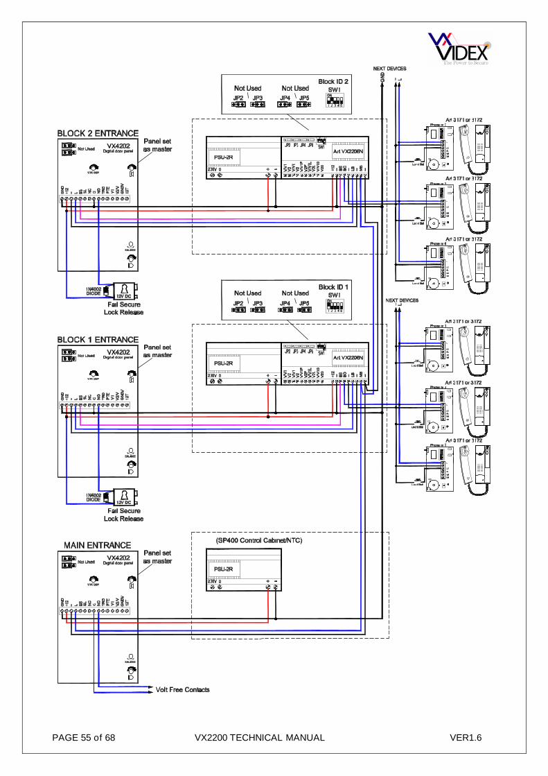
PAGE 55 of 68 VX2200 TECHNICAL MANUAL VER1.6

PAGE 56 of 68 VX2200 TECHNICAL MANUAL VER1.6

PAGE 57 of 68 VX2200 TECHNICAL MANUAL VER1.6

PAGE 58 of 68 VX2200 TECHNICAL MANUAL VER1.6

PAGE 59 of 68 VX2200 TECHNICAL MANUAL VER1.6

PAGE 60 of 68 VX2200 TECHNICAL MANUAL VER1.6

PAGE 61 of 68 VX2200 TECHNICAL MANUAL VER1.6

PAGE 62 of 68 VX2200 TECHNICAL MANUAL VER1.6

PAGE 63 of 68 VX2200 TECHNICAL MANUAL VER1.6
SYSTEM COMPONENTS800 Series Digital Front Panels (2202M, 2202MR)These units are built into a double 800 series module (stainless steel/S or aluminium/A) and have a 2 line16character LCD display, speaker unit and numeric keypad with either 8 alpha buttons [A-H] (VX2202/2202M)or 3 scroll buttons (VX2202R/2202MR) to navigate the “Repertory Names”. A PC based programming kit isalso available (SP37) which includes software and serial cable to simplify the programming of largeinstallations.
Vandal resistant Digital Front Panels (SP300, SP301)These units are based on the 800 series module electronics and have a 2 line 16 character LCD display,speaker unit and numeric keypad, and 12 gauge stainless steel facia with bezel back box.
4000 Series Digital Front Panels (4202, 4202R, 4202V, 4202RV)The 4000 Series door panels have the same features as the 800 series version but are based on the 4000series modular system and can also include mono or colour video within the two module design. Versionswith either alpha buttons [A-F] or scroll buttons are available and include a high contrast blue back lit 2 line16 character LCD display. The face plate is available in either mirror finish stainless steel (standard version)or matt finish anodized aluminium).
Digital panels features:- Call up to 998 users (Version 5.0 software or later) (only 150 with 900 Series telephone);- Call up to 255 users when using 316x telephones;- Open the door by means of an individual personal access code- Enter the “programming menu” (by using a programmable master code), where it is possible to assign:
a. Trade access code for periodic visitors such as postman etcb. one or more apartment numbers for each telephonec. one or more individual access codes (up to 6 digits)d. User name (Scroll facility door panels only)e. the device number for each outdoor stationf. Choose from six languagesg. speech play back systemh. speech time and door opening time (up to 255 seconds);i. Automatic test mode
- Connect up to 10 entrance panels (main or secondary). An installation can consist of main entrances (Which can call all users) andblock entrances (Which can only call users in these blocks). On two level systems of this type a VX2206 bus exchange device isneeded per block.
The LCD display will show all relevant information during the call procedure along with acoustic signals andvoice annunciation.
8000 Series Functional module (8203-0, 8203-1, 8203-2)Built into a single 8000 series module and includes the speaker unit and interfaces to the digital bus. Up to64 push buttons can be added to the interface using the 8843, 8844, 845 expansion button modules. (The8203 is available with either 1 button, 2 buttons or no buttons).
4000 Series Functional Module (4203-0, 4203-1, 4203-2, 4203-1D, 4203-2D)Built into a single 4000 series module and includes the speaker unit plus 4 LED’s to provide call progressinformation. Up to 64 push buttons can be connected (Modules available with button options 0, 1, 2 or 4).Using the standard 4000 series expansion button modules Art.4842, 4843, 4844, 4845, 4842D, 4843D,4844D and 4845D. The module is available with front plate in stainless steel mirror finished (standardversion) or in matt finish anodized aluminium.
4000 Series Functional Module with camera (4283-0, 4283-1, 4283-1D)Built into a single 4000 series module and includes the speaker unit, camera, plus 4 LED’s to provide callprogress information. Up to 32 push buttons can be connected (Modules available with button options 0, 1 or2). Using the standard 4000 series expansion button modules Art.4842, 4843, 4844, 4845, 4842D, 4843D,4844D and 4845D. The module is available with front plate in stainless steel mirror finished (standardversion) or in matt finish anodized aluminium and also with mono or colour camera (Suffix \C for colour).
Vandal resistant Functional panels. (Art.138, VR4K2W)The VR functional panels include the 138 amplifier module. Up to 23 call buttons can be connected and theunit benefits from all the features of the 4000 series module plus a push to exit button input.
Optional 4 way isolation PCB (2204-1)This unit isolates the telephones from the main 2 wire bus preventing a single telephone from compromisingthe system. One PCB is required for every four handsets. (The L & - terminals are isolated by this PCB).
Optional 4 way isolation PCB with full isolation of all signals and bus connection. (2204N)

PAGE 64 of 68 VX2200 TECHNICAL MANUAL VER1.6
This unit isolates the telephones from the main bus preventing a single telephone from compromising thesystem. One PCB is required for every four handsets. (The L, -, +12, S1 & D terminals are isolated by thisPCB). A piggy back video isolation PCB is also available for this audio isolation PCB (Available in both coaxand non-coax video versions).
Non-Coax Video Distributor & 20Vdc Video PSU isolation (316I)Video splitter PCB for no-coax video systems, One required for every four videophones. This PCB can beused as a piggy back card to the 2204N
Coax Video Distributor & 20Vdc Video PSU isolation (894I)As above but for coax video systems.
BUS Exchanger (2206A, 2206V)For use with two level systems with main entrances and block entrances. Enables multiple speech paths(One per block). Use 2206A for audio systems and 2206V for video systems.
BUS Exchanger (2206N)For use with two level systems with main entrances and block entrances. Enables multiple speech paths(One per block). The 2206N allows up to 998 apartments to be called from a main entrance and up to 180apartments per block. The unit can also be used to extend a single level system up to 998 apartments usingmore than one riser bus cable.
Concierge unit (2210A, 2210V)The 2210 allows an operator to handle and to transfer the calls from and to the users. Depending on theselected operating mode (day-night-off), it is possible to carry out different functions from the concierge. Forvideo intercom systems, it is necessary to use 2210V (As 2210A but with additional flat screen monitor).
2 wire bus to 4+1 converter (2280)The 2280 enables the connection of either the Videx Telephone Interface (380) or the Videx apartmentstation (500MM) to the VX2200 system "2 wire" Bus.
Audio telephones (3171, 3172 and 3176)3000 Series intercoms for the VX2200 Digital System. All 3 intercoms have a door-open/call to conciergebutton plus an electronic call tone with a 3 level volume control which can be adjusted by the user. The 3171and 3172 have a dry contact service push button and the 3172 has a slide privacy switch. The 3176 has atimed privacy push button with red privacy LED and a green “door open” LED (The door open LED requiresan additional wire).
Audio apartment stations (5178, 5178/CA and 5178/CR, VR5178)5000 Series surface apartment stations available in white, silver or carbon fibre finishes. Including featuressuch as half duplex handsfree speech or optional simplex speech mode, timed privacy facility with LED, dooropen LED and additional service buttons. Also available in vandal resistant flush.
Basic function audio telephone (3161, 3162)3000 series low cost telephones with restricted features. The 3161 has a “door open” button and “service”button. The 3162 also includes a slide mute switch. These telephones can only be used on audio systemswithout isolation or a concierge.
Videophones (3371, 3376, 3471, 3476)3000 Series videophones with coax and non coax video inputs. The 3371 (3471 for colour video) has 5buttons: “door open”/call to concierge, camera recall/alarm and 3 service push button. The 3376 (3476 forcolour video) is similar to the 3371 but also includes timed privacy with red privacy LED, door open LED(Requires one additional wire) and one less service push button.
Videomonitors (5478, 5478/CA, 5478/CR, VR5478)5000 Series videomonitors with coax and non coax video inputs. Including colour video, timed privacyfacility, half duplex handsfree speech (Optional handset kit or simplex speech option) and spare servicebuttons. A flush mounting kit is also available for these monitors which are also available in white, silver orcarbon fibre affect finishes. Also available in vandal resistant flush.
Videophone (3678)3600 Series videophones with coax and non coax video inputs. Colour TFT 3.5” monitor with OSD. 3buttons: “door open”/call to concierge, camera recall/call answer and privacy. Includes both handset andhandsfree speech, timed privacy facility and privacy, door open and answer LED’s
PAGE 65 of 68 VX2200 TECHNICAL MANUAL VER1.6
Extension sounder (512D)Extension Sounder in a white plastic wall mount box. Connects directly to the 2 wire bus.
Extension relay (512DR)As the 512D but with a dry contact relay (24V 100mA) instead of the sounder.
Non-coax camera module (830/NC, 830C/NC)800 series camera module with infrared illumination. “No coax” required. (Colour camera 830C/NC has whiteLED’s as oppose to IR LED’s)
Coax camera (830, 830C)As above but for coax video systems. Use 830NC /830NC/C for non-coax camera.
Coax/Non-coax camera (4830, 4830C)A 4000 series camera with both coax and non-coax connections. Available in mono or colour.
1A DIN Rail Power Supply Unit (521B)For audio systems with battery back-up facility, 230Vac / 13Vdc/ac – 1 Amp.
Video Power Supply (893N1)For video systems, 230 Vac / 20Vdc – 1 A peak current (0.8 A continuous current).
Audio control cabinet (SP400, SP405)Lockable control cabinet for one door (SP400) and up to 4 doors (SP405) audio systems. Includes aBST/GMT time clock, PSU and facility for a backup battery.
Video control cabinet (SP410, SP415)Lockable control cabinet for one door (SP410) and up to 4 doors (SP415) video systems. Includes aBST/GMT time clock, PSU’s for both audio and video, video switching PCB (Multipe door cabinet only) andfacility for a backup battery (Audio backup only).
Non-Coax Video Distributor (316, 316N)Video splitter for no-coax video systems, One required for every four videophones.
Coax Video Distributor (894, 894N)As above but for coax video systems.

PAGE 66 of 68 VX2200 TECHNICAL MANUAL VER1.6
PAGE 67 of 68 VX2200 TECHNICAL MANUAL VER1.6

PAGE 68 of 68 VX2200 TECHNICAL MANUAL VER1.6
Northern OfficeVidex Security LtdUnit 4-7 Chillingham Ind. Est.Newcastle Upon TyneNE6 2XXTEL 0870 300 1240FAX 0191 224 5678
Southern Office1 OspreyTrinity ParkTrinity WayLondonE4 8TDFAX 0208 523 5825
TECHNICAL [email protected] 0191 224 3174FAX 0191 224 4938http://www.videx-security.com